torque control of induction machines - lth 13/l12(inductionmotor).pdfdelta rect mod angle rec_to_pol...
TRANSCRIPT

Industrial Electrical Engineering and Automation
Lund University, Sweden
Torque Control of
Induction Machines ...
… as compared to PMSM

Ind
ustr
ial E
lectr
ica
l E
ng
ine
erin
g a
nd
Au
tom
atio
n
© Namn Namn Föredragstitel
The Induction Motor
Three Phase Stator
No Magnets in the Rotor
Rotor as Short Circuited
”Cage”
The rotor current must be
induced
Three Phase Stator
Three phase power
electronics

Ind
ustr
ial E
lectr
ica
l E
ng
ine
erin
g a
nd
Au
tom
atio
n
© Namn Namn Föredragstitel
A look under the hood
Motoraxel
Kullager
Lagersköld
Uttagslåda
Fläkt
StatorplåtpaketRotor
Statorlindning
Kylfläns
Ind
ustr
ial E
lectr
ica
l E
ng
ine
erin
g a
nd
Au
tom
atio
n
© Namn Namn Föredragstitel
Advantages
• Self starting when connected to the power
grid
• Robust and reliable
• Cheap
• Low maintenance
• Standardized

Ind
ustr
ial E
lectr
ica
l E
ng
ine
erin
g a
nd
Au
tom
atio
n
© Namn Namn Föredragstitel
AM - dynamics
Start here … Move the stator current one
step – what happens in the
rotor?

Ind
ustr
ial E
lectr
ica
l E
ng
ine
erin
g a
nd
Au
tom
atio
n
© Namn Namn Föredragstitel
si
si
ri
Statorströmvektor- momentbildande komponent- magnetiserande komponent.
Rotorströmvektor
Consequencies
• The rotor current is
– Proportional to
The stator flux and
The speed difference (both tangentially and radially)
– Inversely proportional to the rotor resistance
– 90 degrees lag versus the flux
Ind
ustr
ial E
lectr
ica
l E
ng
ine
erin
g a
nd
Au
tom
atio
n
© Namn Namn Föredragstitel
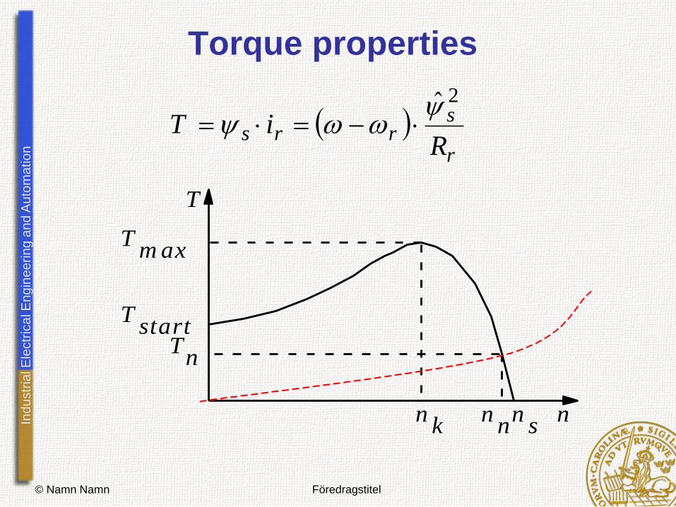
Torque properties
r
srrs
RiT
2̂
T start T n
T m ax
n n n s
n
T
n k
Ind
ustr
ial E
lectr
ica
l E
ng
ine
erin
g a
nd
Au
tom
atio
n
© Namn Namn Föredragstitel
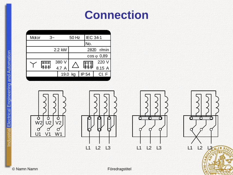
Connection
Motor 3~ 50 Hz IEC 34-1
No.
kW2.2 r/min2820
cos 0,89
V
A
380
4.7
V
A
220
8.15
IP 54 FCl.kg19.0
U1 V1 W1
W2 U2 V2
L1 L2 L3L1 L2 L3 L1 L2 L3

Ind
ustr
ial E
lectr
ica
l E
ng
ine
erin
g a
nd
Au
tom
atio
n
© Namn Namn Föredragstitel
Single phase operation
• Steinmetz connection
• Shaded pole motor
Ind
ustr
ial E
lectr
ica
l E
ng
ine
erin
g a
nd
Au
tom
atio
n
© Namn Namn Föredragstitel
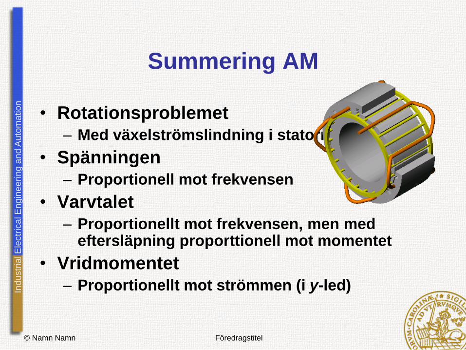
Summering AM
• Rotationsproblemet – Med växelströmslindning i statorn
• Spänningen – Proportionell mot frekvensen
• Varvtalet – Proportionellt mot frekvensen, men med
eftersläpning proporttionell mot momentet
• Vridmomentet – Proportionellt mot strömmen (i y-led)
Ind
ustr
ial E
lectr
ica
l E
ng
ine
erin
g a
nd
Au
tom
atio
n
© Namn Namn Föredragstitel
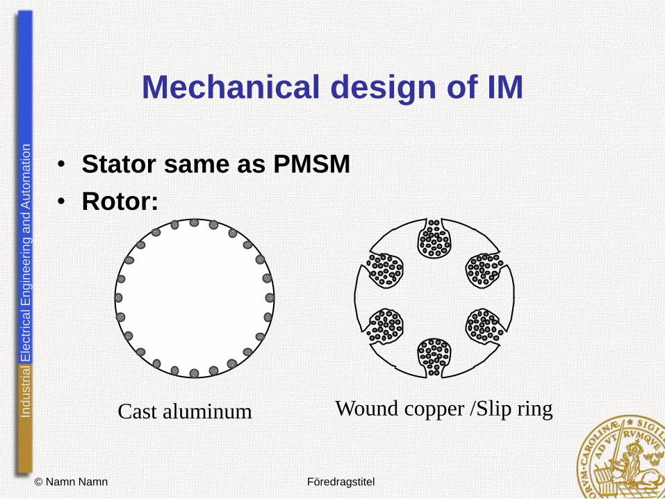
Mechanical design of IM
• Stator same as PMSM
• Rotor:
Cast aluminum Wound copper /Slip ring

Ind
ustr
ial E
lectr
ica
l E
ng
ine
erin
g a
nd
Au
tom
atio
n
© Namn Namn Föredragstitel
Slip ring rotor
The rotor can be:
1 Short circuited
2 Given an external rotor
resistance
3 Fed by power electronics

Ind
ustr
ial E
lectr
ica
l E
ng
ine
erin
g a
nd
Au
tom
atio
n
© Namn Namn Föredragstitel
Mathematical model
• Stator
• Rotor
ri
si
r
r
s
s
su
su
dt
d s
ss iR dt
diRu
dt
diRu
rrsr
ssss
Ind
ustr
ial E
lectr
ica
l E
ng
ine
erin
g a
nd
Au
tom
atio
n
© Namn Namn Föredragstitel
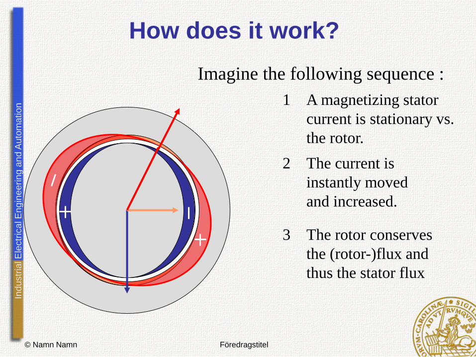
How does it work?
1 A magnetizing stator
current is stationary vs.
the rotor.
2 The current is
instantly moved
and increased.
3 The rotor conserves
the (rotor-)flux and
thus the stator flux
Imagine the following sequence :
Ind
ustr
ial E
lectr
ica
l E
ng
ine
erin
g a
nd
Au
tom
atio
n
© Namn Namn Föredragstitel
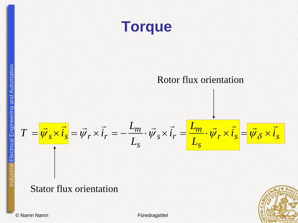
Torque
Rotor flux orientation
Stator flux orientation
ssrs
mrs
s
mrrss ii
L
Li
L
LiiT

Ind
ustr
ial E
lectr
ica
l E
ng
ine
erin
g a
nd
Au
tom
atio
n
© Namn Namn Föredragstitel
Vector control of Induction motors
• Flux estimation (rotor- or stator- the most
difficult part)
Ind
ustr
ial E
lectr
ica
l E
ng
ine
erin
g a
nd
Au
tom
atio
n
© Namn Namn Föredragstitel
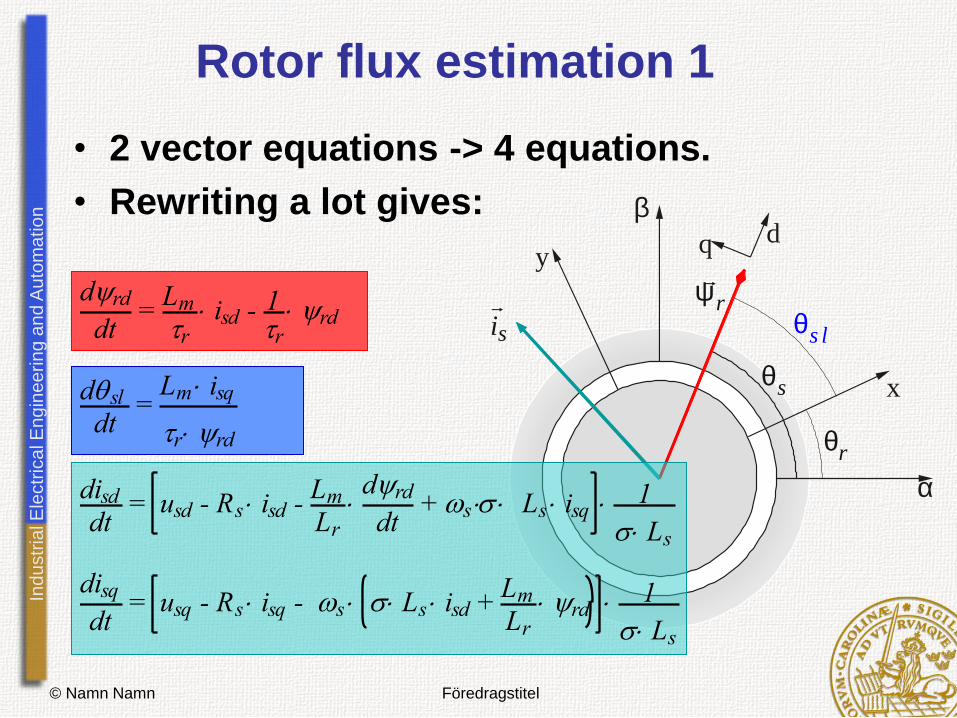
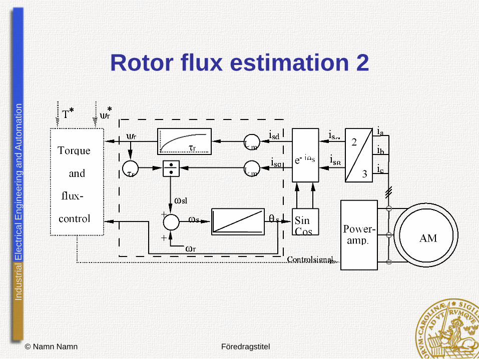
Rotor flux estimation 1
r y
s i
r q
s l q
a
b
x
y
s q
d q
drd
dt =
Lm
r isd - 1
r rd
dsl
dt =
Lm isq
r rd disddt
= usd - Rs isd - Lm
Lr
drd
dt + s Ls isq
1
Ls disq
dt = usq - Rs isq - s Ls isd +
Lm
Lr rd 1
Ls
• 2 vector equations -> 4 equations.
• Rewriting a lot gives:
Ind
ustr
ial E
lectr
ica
l E
ng
ine
erin
g a
nd
Au
tom
atio
n
© Namn Namn Föredragstitel
Rotor flux estimation 2
Ind
ustr
ial E
lectr
ica
l E
ng
ine
erin
g a
nd
Au
tom
atio
n
© Namn Namn Föredragstitel
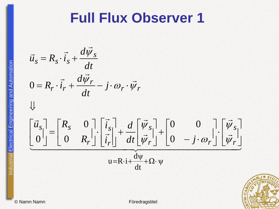
Full Flux Observer 1
ψΩψ
dt
diRu
r
s
rr
s
r
s
r
ss
rrr
rr
ssss
jdt
d
i
i
R
Ru
jdt
diR
dt
diRu
0
00
0
0
0
0
Ind
ustr
ial E
lectr
ica
l E
ng
ine
erin
g a
nd
Au
tom
atio
n
© Namn Namn Föredragstitel
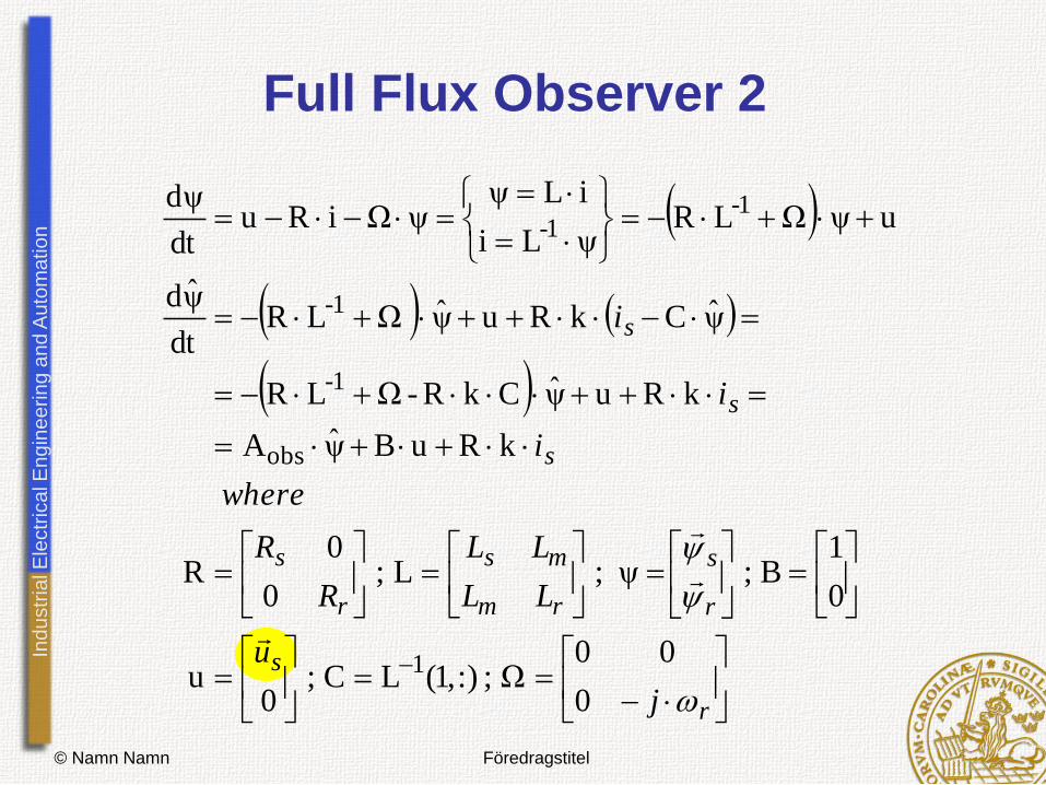
Full Flux Observer 2
r
s
r
s
rm
ms
r
s
s
s
s
j
u
LL
LL
R
R
where
i
i
i
0
00;:),1(;
0
0
1;;;
0
0
ˆ
ˆ
ˆˆˆ
1 Ω
ψ
ψ
ψΩ
ψψΩψ
ψΩLψLi
iLψψΩ
ψ 1-1-
LCu
BLR
kRuBA
kRuCkR-LR
CkRuLRdt
d
uRiRudt
d
obs
1-
1-
Ind
ustr
ial E
lectr
ica
l E
ng
ine
erin
g a
nd
Au
tom
atio
n
© Namn Namn Föredragstitel
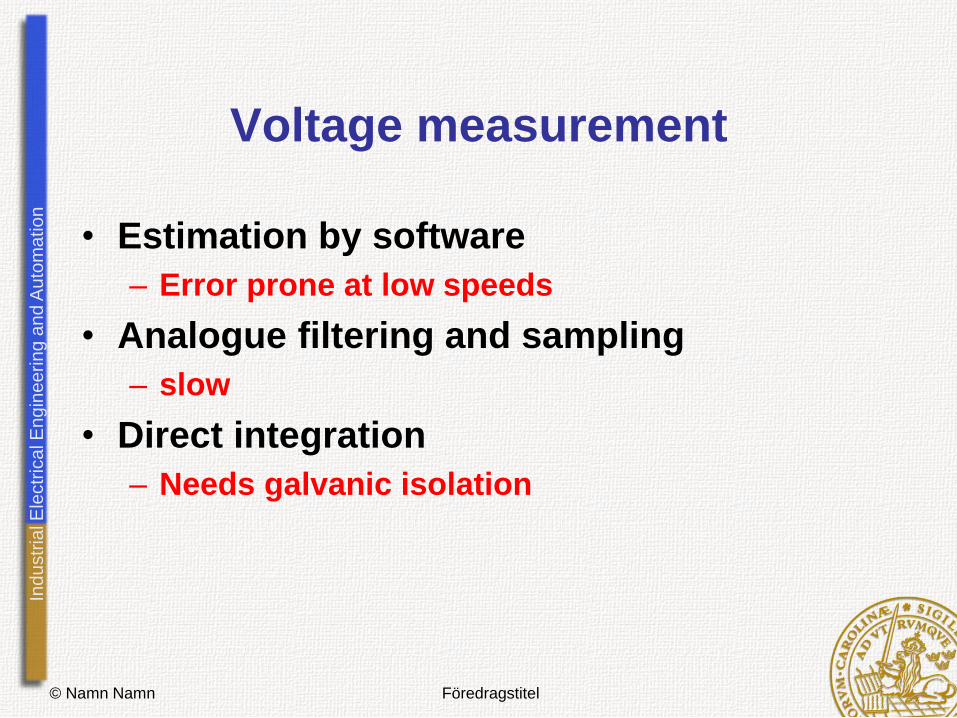
Voltage measurement
• Estimation by software
– Error prone at low speeds
• Analogue filtering and sampling
– slow
• Direct integration
– Needs galvanic isolation
Ind
ustr
ial E
lectr
ica
l E
ng
ine
erin
g a
nd
Au
tom
atio
n
© Namn Namn Föredragstitel
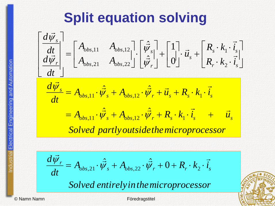
Split equation solving
ssormicroprocetheinentirelySolved
ikRAAdt
d
ssormicroprocetheoutsidepartlySolved
uikRAA
ikRuAAdt
d
ikR
ikRu
AA
AA
dt
ddt
d
srrobssobsr
sssrobssobs
sssrobssobss
sr
ss
s
r
s
obsobs
obsobs
r
s
222,21,
112,11,
112,11,
2
1
22,21,
12,11,
0ˆˆ
ˆˆ
ˆˆ
0
1
ˆ
ˆ
Ind
ustr
ial E
lectr
ica
l E
ng
ine
erin
g a
nd
Au
tom
atio
n
© Namn Namn Föredragstitel
Direct integration implemented
Ind
ustr
ial E
lectr
ica
l E
ng
ine
erin
g a
nd
Au
tom
atio
n
© Namn Namn Föredragstitel
Stator Flux Oriented Vector Control of
Torque and Flux
• 3 advantages:
– In a synchronously rotating reference frame,
there are no stationary errors since all
reference values are constant in stationarity
– The stator flux vector can in most cases be
observed with high accuracy and low
parameter sensitivity
– Direct flux control can be applied
Ind
ustr
ial E
lectr
ica
l E
ng
ine
erin
g a
nd
Au
tom
atio
n
© Namn Namn Föredragstitel
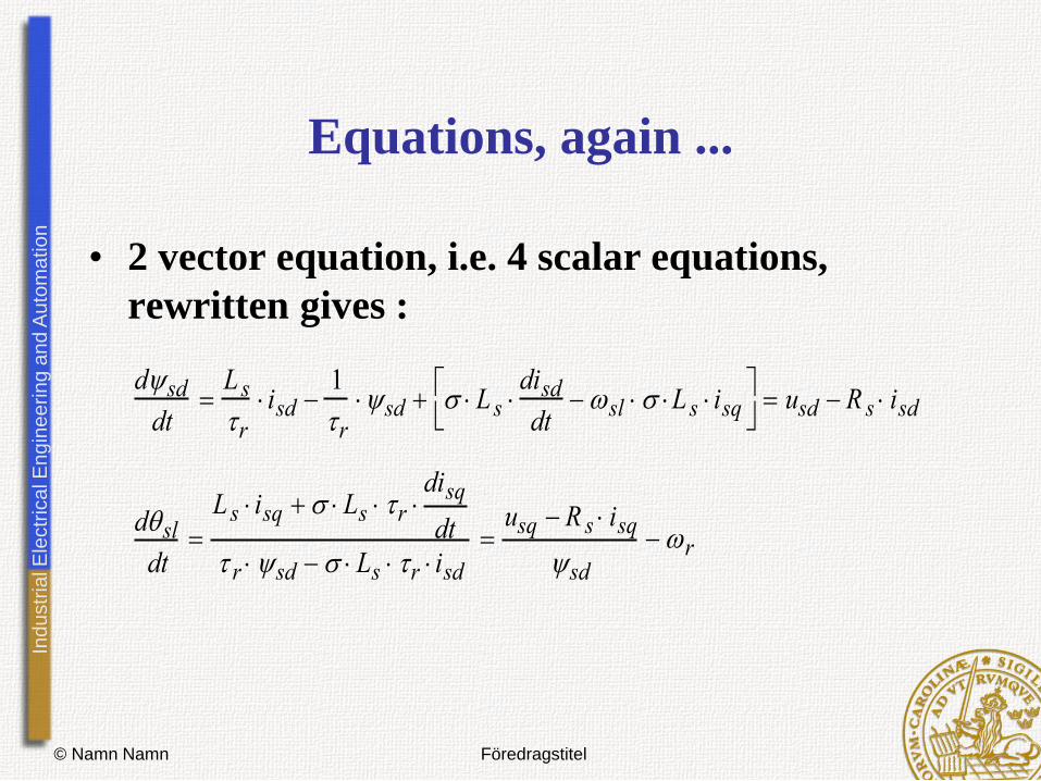
Equations, again ...
dsd
dt
L s
r
isd 1
r
sd L s disd
dt sl L s isq
usd R s isd
dsl
dt
L s isq Ls r disq
dt
r sd Ls r isd
usq R s isq
sd
r
• 2 vector equation, i.e. 4 scalar equations,
rewritten gives :

Ind
ustr
ial E
lectr
ica
l E
ng
ine
erin
g a
nd
Au
tom
atio
n
© Namn Namn Föredragstitel
Direct Flux Vector Control
s
sdsd
s
sds
sdssd
s
sdsdsdssd
sdsdssd
T
kk
L
kR
tystationariiniL
T
kkkkiRku
dt
tdtiRtu
)()()(
)()()1,()(
)()()(
*
**

Ind
ustr
ial E
lectr
ica
l E
ng
ine
erin
g a
nd
Au
tom
atio
n
© Namn Namn Föredragstitel
Control of the Torque producing
current component : 1
usq = Rs isq + r sd + Ls isq + Ls r
disq
dt
r sd - Ls r isd
sd
sdrsq
rssqrs
sdrsq
ssqrssq
dt
diLLiRR
dt
diLiRRu
)()(
)(
• The remaining two rewritten scalar equations:
Ind
ustr
ial E
lectr
ica
l E
ng
ine
erin
g a
nd
Au
tom
atio
n
© Namn Namn Föredragstitel
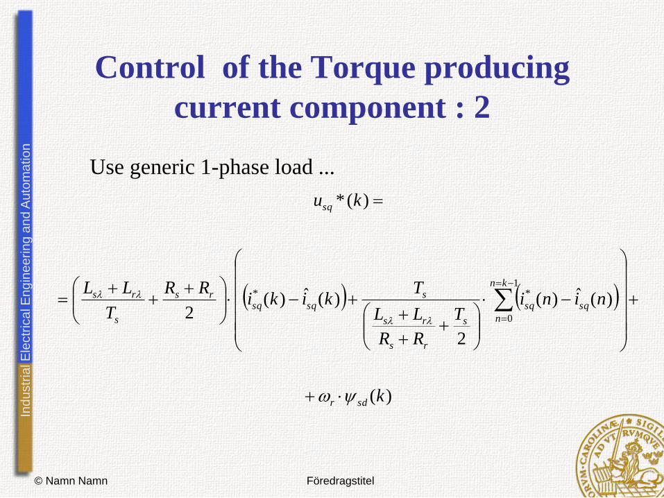
Control of the Torque producing
current component : 2
)(
)(ˆ)(
2
)(ˆ)(2
)(*
1
0
**
k
niniT
RR
LL
Tkiki
RR
T
LL
ku
sdr
kn
n
sqsq
s
rs
rs
ssqsq
rs
s
rs
sq
Use generic 1-phase load ...

Ind
ustr
ial E
lectr
ica
l E
ng
ine
erin
g a
nd
Au
tom
atio
n
© Namn Namn Föredragstitel
Vector Control System
ysqref
ysdref
Rough rotor speed replacement
• ws
1
us*
Demux
Ü>P isd &P isq_old
Ü> isq_ref
Demux
Ü> isd & isq
• delta
rect
mod
angle
rec_to_pol
old psis
old angle
v ect
angle
Out
alfa/beta Ü> d/q1
v ect
angle
Out
alfa/beta Ü> d/q
1
10e-3s+1
Transfer Fcn
ref
act
e
y
PIE
Torque control
ref
act
e
y
PIE
Stator flux control
Scope1
Scope
Saturation
Mux
Mux1
Ground
1/Ts
2/p
-1
v ect
angle
Out
d/q > alfa/beta
4
Tref
3
is
2
PsiR
1
Psiref

Ind
ustr
ial E
lectr
ica
l E
ng
ine
erin
g a
nd
Au
tom
atio
n
© Namn Namn Föredragstitel
DTC
• Compare to DCC.
• Replace with
• Replace with T sdi sd
sqi

Ind
ustr
ial E
lectr
ica
l E
ng
ine
erin
g a
nd
Au
tom
atio
n
© Namn Namn Föredragstitel
DTC system
increase/
decrease iq
rest
is5
vect
4 isdq
3
sc
2
sb
1
sa
f(u)
f(u)
vector
f(u)
f(u)
sector
rect
mod
angle
emf
rec_to_pol
In1 Out1
low speed?
increase/
decrease id
v ect
angle
Out
alfa/beta Ü> d/q
XY Graph
Scope3
Scope2Scope1
Memory
1
-1
2-D T[k]
Demux
[1 1 1]
[-1 -1 -1]
[1 -1 -1]
[1 1 -1]
[1 -1 1]
[-1 -1 1]
[-1 1 1]
7
8
[-1 1 -1]
|u|
Demux
-> isd & isq
4
Psis
3
T*
2
i
1
Psis*
Ind
ustr
ial E
lectr
ica
l E
ng
ine
erin
g a
nd
Au
tom
atio
n
© Namn Namn Föredragstitel
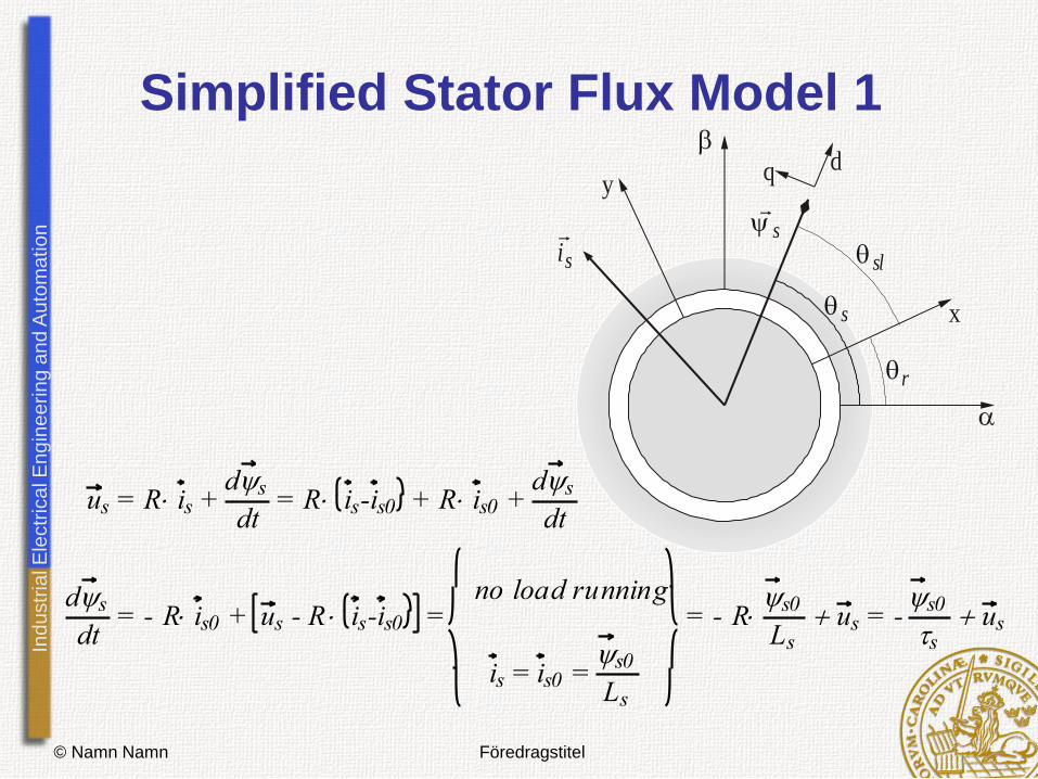
Simplified Stator Flux Model 1
si
r
sl
x
y
s
dq
s
us = R is + ds
dt = R is-is0 + R is0 +
ds
dt
ds
dt = - R is0 + us - R is-is0 =
no load running
is = is0 = s0
Ls
= - Rs0
Lsus = -
s0
sus
Ind
ustr
ial E
lectr
ica
l E
ng
ine
erin
g a
nd
Au
tom
atio
n
© Namn Namn Föredragstitel
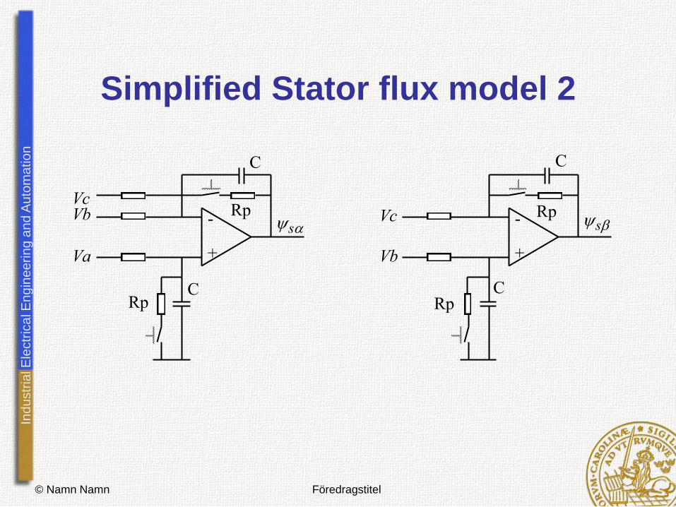
Simplified Stator flux model 2
- +
- +Va
VbVc
Vb
VcRp
C
Rp
Rp
RpC
C
C
ss
Ind
ustr
ial E
lectr
ica
l E
ng
ine
erin
g a
nd
Au
tom
atio
n
© Namn Namn Föredragstitel
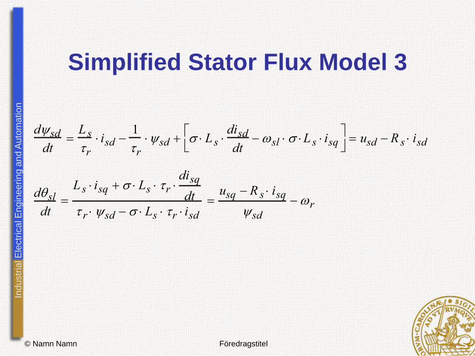
Simplified Stator Flux Model 3
dsd
dt
L s
r
isd 1
r
sd L s disd
dt sl L s isq
usd R s isd
dsl
dt
L s isq Ls r disq
dt
r sd Ls r isd
usq R s isq
sd
r
Ind
ustr
ial E
lectr
ica
l E
ng
ine
erin
g a
nd
Au
tom
atio
n
© Namn Namn Föredragstitel
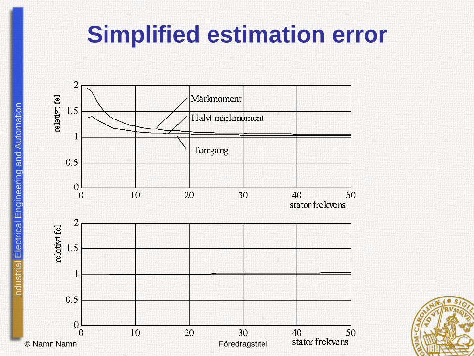
Simplified estimation error

Ind
ustr
ial E
lectr
ica
l E
ng
ine
erin
g a
nd
Au
tom
atio
n
© Namn Namn Föredragstitel
Relation iq/id in stator flux frame
Ind
ustr
ial E
lectr
ica
l E
ng
ine
erin
g a
nd
Au
tom
atio
n
© Namn Namn Föredragstitel
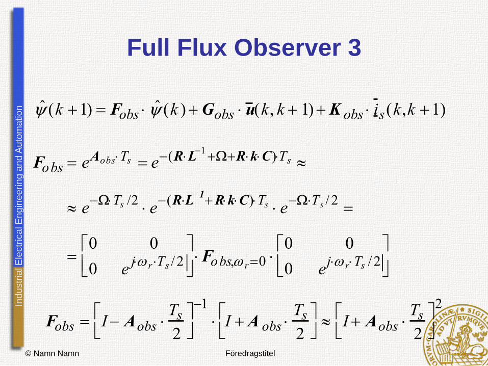
Full Flux Observer 3
ˆ (k 1) Fobs ˆ (k )Gobs u (k, k 1)K obs i s(k,k 1)
Fobs eAobsTs e(RL1RkC)Ts
eTs /2
e(RL
1RkC)Ts e
Ts / 2
0 0
0 ej r Ts / 2
Fobs, r0
0 0
0 ej rTs / 2
Fobs I Aobs Ts
2
1
I A obs Ts
2
I Aobs
Ts
2
2
Ind
ustr
ial E
lectr
ica
l E
ng
ine
erin
g a
nd
Au
tom
atio
n
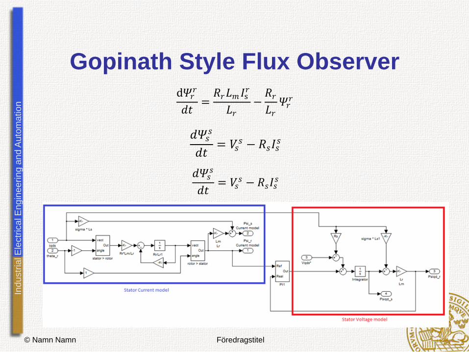
Gopinath Style Flux Observer
© Namn Namn Föredragstitel
d𝛹𝑟𝑟
𝑑𝑡=𝑅𝑟𝐿𝑚 𝐼s
𝑟
𝐿𝑟−𝑅𝑟𝐿𝑟𝛹𝑟𝑟
𝑑𝛹𝑠𝑠
𝑑𝑡= 𝑉𝑠
𝑠 − 𝑅𝑠𝐼𝑠𝑠
𝑑𝛹𝑠𝑠
𝑑𝑡= 𝑉𝑠
𝑠 − 𝑅𝑠𝐼𝑠𝑠

Ind
ustr
ial E
lectr
ica
l E
ng
ine
erin
g a
nd
Au
tom
atio
n
DB-DTFC
© Namn Namn Föredragstitel
s
ss iL
rr iL
r
si
ri
Ind
ustr
ial E
lectr
ica
l E
ng
ine
erin
g a
nd
Au
tom
atio
n
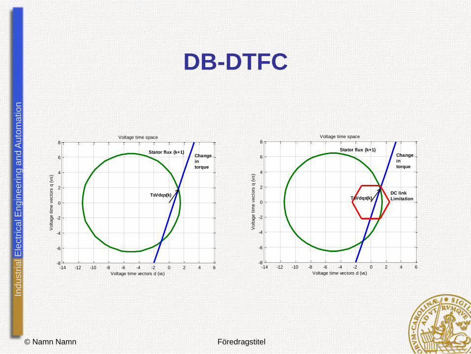
DB-DTFC
© Namn Namn Föredragstitel
-14 -12 -10 -8 -6 -4 -2 0 2 4 6-8
-6
-4
-2
0
2
4
6
8
Voltage time vectors d (vs)
Voltage t
ime v
ecto
rs q
(vs)
Voltage time space
TsVdqs(k)
Stator flux (k+1)Change
in
torque
-14 -12 -10 -8 -6 -4 -2 0 2 4 6-8
-6
-4
-2
0
2
4
6
8
Voltage time vectors d (vs)
Voltage t
ime v
ecto
rs q
(vs)
Voltage time space
DC link
Limitation
Change
in
torque
Stator flux (k+1)
TsVdqs(k)