topolnicki et al application of micropiles for gdansk ... 3 - topolnicki - application... ·...
TRANSCRIPT
1
APPLICATION OF MICROPILES FOR UPLIFT CONTROL AND FOUNDATION OF LARGE ACCESS RAMPS OF AN UNDERWATER ROAD TUNNEL IN GDAŃSK
Michał Topolnicki1, Rafał Buca2, Oskar Mitrosz3 and Waldemar Kwiatkowski4
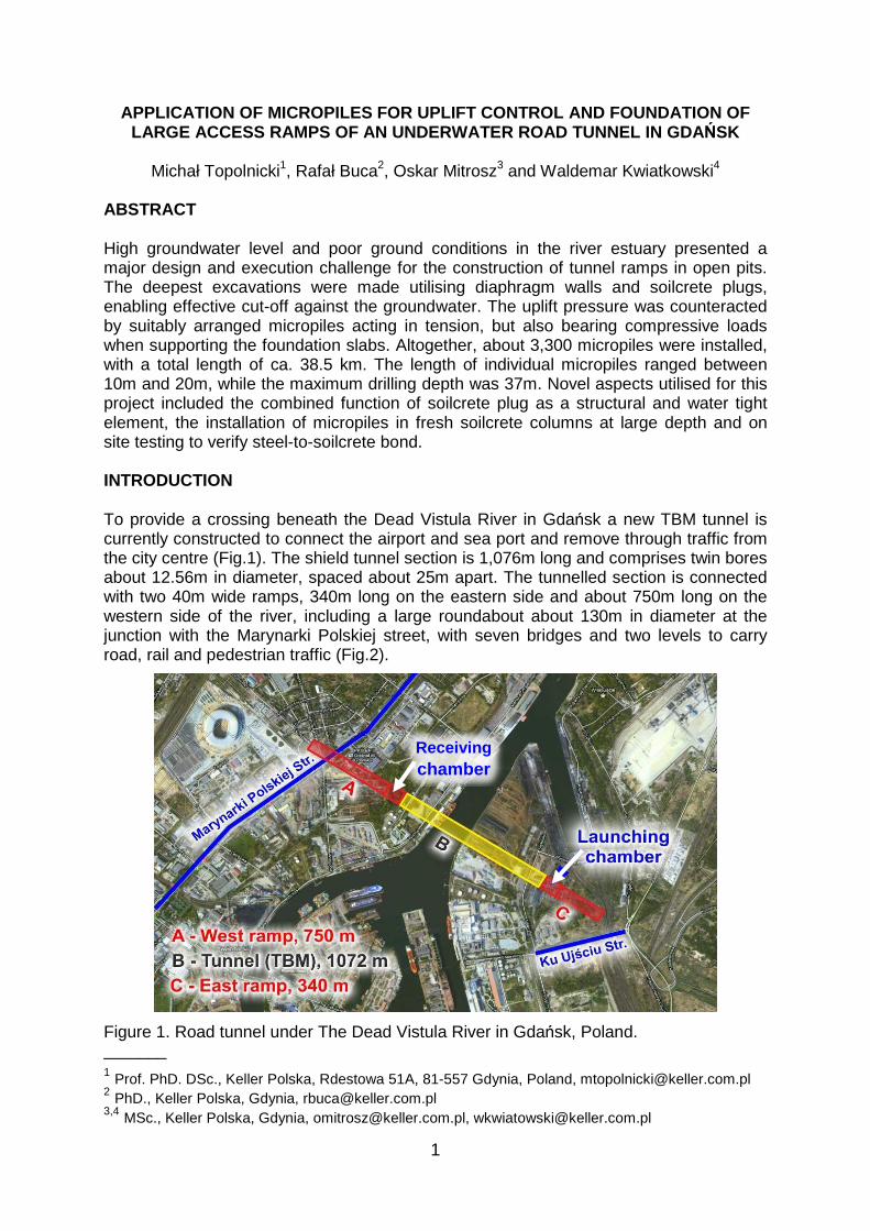
ABSTRACT High groundwater level and poor ground conditions in the river estuary presented a major design and execution challenge for the construction of tunnel ramps in open pits. The deepest excavations were made utilising diaphragm walls and soilcrete plugs, enabling effective cut-off against the groundwater. The uplift pressure was counteracted by suitably arranged micropiles acting in tension, but also bearing compressive loads when supporting the foundation slabs. Altogether, about 3,300 micropiles were installed, with a total length of ca. 38.5 km. The length of individual micropiles ranged between 10m and 20m, while the maximum drilling depth was 37m. Novel aspects utilised for this project included the combined function of soilcrete plug as a structural and water tight element, the installation of micropiles in fresh soilcrete columns at large depth and on site testing to verify steel-to-soilcrete bond. INTRODUCTION To provide a crossing beneath the Dead Vistula River in Gdańsk a new TBM tunnel is currently constructed to connect the airport and sea port and remove through traffic from the city centre (Fig.1). The shield tunnel section is 1,076m long and comprises twin bores about 12.56m in diameter, spaced about 25m apart. The tunnelled section is connected with two 40m wide ramps, 340m long on the eastern side and about 750m long on the western side of the river, including a large roundabout about 130m in diameter at the junction with the Marynarki Polskiej street, with seven bridges and two levels to carry road, rail and pedestrian traffic (Fig.2).
Figure 1. Road tunnel under The Dead Vistula River in Gdańsk, Poland. _______ 1 Prof. PhD. DSc., Keller Polska, Rdestowa 51A, 81-557 Gdynia, Poland, [email protected] 2 PhD., Keller Polska, Gdynia, [email protected] 3,4 MSc., Keller Polska, Gdynia, [email protected], [email protected]
Receiving chamber

2
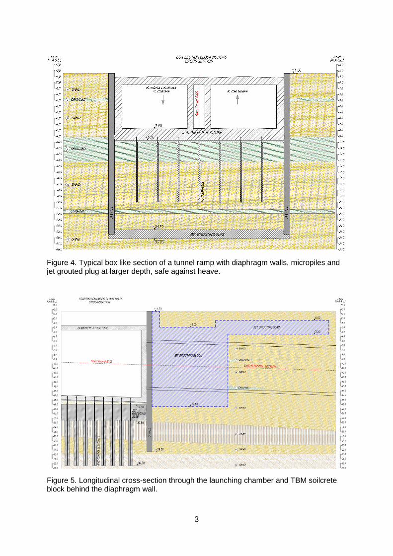
Figure 2. Longitudinal cross-section of the tunnel [1]. The reinforced concrete ramps have been designed as watertight U-shape and box like sections, consisting of a monolithic section constructed by connecting the foundation slabs and walls (Fig’s 3 and 4). At the eastern side of the river, the launching chamber is located together with a jet grouted soilcrete block and plug enabling the tunnel boring machine (TBM) to begin boring (Fig.5). The TBM receiving chamber is located at the western river bank. Both tunnel ramps are divided into blocks connected with expansion joints, where a typical single block length varied from 10 to 12.5m. Respective excavation pits are designed up to 22m deep. The tunnel structure is protected against maximum water level of +2.5m above sea level (ASL) during normal exploitation, representing extreme flood level (EFL). During construction stages two design water levels of +0.5m and +1.5m ASL have been also used in the analyses (cf. Fig’s 9 and 10).
Figure 3. Typical U-shaped block structure of a tunnel ramp with diaphragm walls, micropiles and natural clayey sealing.
3
1
4 5 2
E W Launching chamber
Receiving chamber
3
Figure 4. Typical box like section of a tunnel ramp with diaphragm walls, micropiles and jet grouted plug at larger depth, safe against heave.
Figure 5. Longitudinal cross-section through the launching chamber and TBM soilcrete block behind the diaphragm wall.

4
GEOTECHNICAL CONDITIONS The tunnel is constructed in difficult geotechnical conditions at the Vistula River estuary, characterized by an alternating presence of marine and alluvial deposits developed in the form of sands and soft organic silt, with very low strength and deformation parameters [2]. In the bottom of the delta series, at a depth of about 23m below the ground surface, there is a layer of low-permeable glacial drifts developed in the form of silty clays. On the western riverbank, continuous natural clay layer about 5m thick, which could be used as a natural cut-off barrier, was found beneath the entire tunnel route, as confirmed by supplementary geotechnical investigation [3]. On the other side of the river a layer of low-permeable glacial drifts is not continuous and its thickness decreases with distance from Dead Vistula. The groundwater in the area of the tunnel is mostly confined and its level is stabilized at a depth of about 0.5m ASL, which is less than 1m below the working platform. This caused additional problems and required elevating the guide walls during the construction of the diaphragm walls. ADOPTED EXCAVATION PIT PROTECTION AND ANCHORING SYSTEMS Depending on the excavation depth and the presence of low-permeable strata in the subsoil, three main protection systems were proposed and designed by the geotechnical contractor to limit the inflow of groundwater into the final excavation.
The first solution adopted for the shallowest tunnel blocks, where the excavation depth did not exceed about 6m, was to construct a temporary steel sheet pile wall embedded in the low-permeable strata of organic silt. The sheet pile wall will be removed after the permanent reinforced concrete structure of the tunnel is constructed. In these sections, 300mm diameter micropiles were designed as unreinforced concrete elements (acc. to PN-EN 14199, 7.4.3) capable of bearing compressive loads only. A single 32mm bar, installed in the upper six meters of the micropiles (acc. to PN-EN 12699, 7.8.2.6 and 7.8.2.9), provided additional capacity for extraordinary loads resulting from construction on the site and eventual pile eccentricity. Static load tests were performed on trial micropiles to 200% of the design load, which was 2 x 650 = 1,300kN (Fig.6).
Figure 6. Static load test of a single micropile diameter 300mm, acting in compression.
The second system applied to the deeper excavations consisted of diaphragm walls embedded about 1.5m into the low-permeable silty clay treated as natural clayey sealing within the area of its documented presence (Fig.3). In case the low-permeable layer was not continuous or situated too shallow to the excavation level, which could potentially cause the loss of equilibrium of the excavation bottom, the slurry diaphragm walls and horizontal jet grouted plugs at larger depth, safe against heave, were designed (Fig.4). Micropiles acting in tension and capable of bearing compressive loads to support the ramp foundation slab compensated the groundwater uplift pressure.
0 200 400 600 800 1000 1200 1400
0
2
4
6
8
Compressive force, kN
Pile
set
tlem
ent,
mm
5
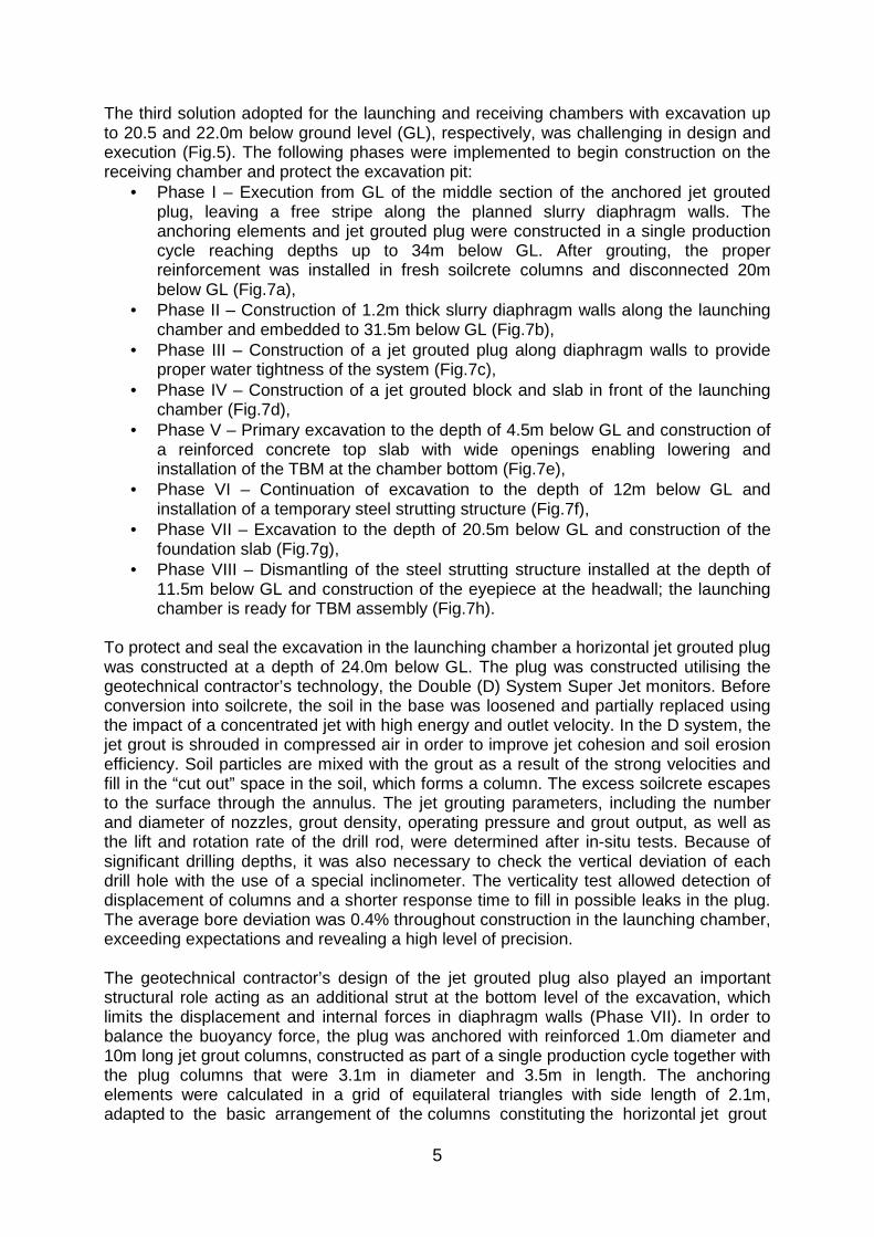
The third solution adopted for the launching and receiving chambers with excavation up to 20.5 and 22.0m below ground level (GL), respectively, was challenging in design and execution (Fig.5). The following phases were implemented to begin construction on the receiving chamber and protect the excavation pit:
• Phase I – Execution from GL of the middle section of the anchored jet grouted plug, leaving a free stripe along the planned slurry diaphragm walls. The anchoring elements and jet grouted plug were constructed in a single production cycle reaching depths up to 34m below GL. After grouting, the proper reinforcement was installed in fresh soilcrete columns and disconnected 20m below GL (Fig.7a),
• Phase II – Construction of 1.2m thick slurry diaphragm walls along the launching chamber and embedded to 31.5m below GL (Fig.7b),
• Phase III – Construction of a jet grouted plug along diaphragm walls to provide proper water tightness of the system (Fig.7c),
• Phase IV – Construction of a jet grouted block and slab in front of the launching chamber (Fig.7d),
• Phase V – Primary excavation to the depth of 4.5m below GL and construction of a reinforced concrete top slab with wide openings enabling lowering and installation of the TBM at the chamber bottom (Fig.7e),
• Phase VI – Continuation of excavation to the depth of 12m below GL and installation of a temporary steel strutting structure (Fig.7f),
• Phase VII – Excavation to the depth of 20.5m below GL and construction of the foundation slab (Fig.7g),
• Phase VIII – Dismantling of the steel strutting structure installed at the depth of 11.5m below GL and construction of the eyepiece at the headwall; the launching chamber is ready for TBM assembly (Fig.7h).
To protect and seal the excavation in the launching chamber a horizontal jet grouted plug was constructed at a depth of 24.0m below GL. The plug was constructed utilising the geotechnical contractor’s technology, the Double (D) System Super Jet monitors. Before conversion into soilcrete, the soil in the base was loosened and partially replaced using the impact of a concentrated jet with high energy and outlet velocity. In the D system, the jet grout is shrouded in compressed air in order to improve jet cohesion and soil erosion efficiency. Soil particles are mixed with the grout as a result of the strong velocities and fill in the “cut out” space in the soil, which forms a column. The excess soilcrete escapes to the surface through the annulus. The jet grouting parameters, including the number and diameter of nozzles, grout density, operating pressure and grout output, as well as the lift and rotation rate of the drill rod, were determined after in-situ tests. Because of significant drilling depths, it was also necessary to check the vertical deviation of each drill hole with the use of a special inclinometer. The verticality test allowed detection of displacement of columns and a shorter response time to fill in possible leaks in the plug. The average bore deviation was 0.4% throughout construction in the launching chamber, exceeding expectations and revealing a high level of precision. The geotechnical contractor’s design of the jet grouted plug also played an important structural role acting as an additional strut at the bottom level of the excavation, which limits the displacement and internal forces in diaphragm walls (Phase VII). In order to balance the buoyancy force, the plug was anchored with reinforced 1.0m diameter and 10m long jet grout columns, constructed as part of a single production cycle together with the plug columns that were 3.1m in diameter and 3.5m in length. The anchoring elements were calculated in a grid of equilateral triangles with side length of 2.1m, adapted to the basic arrangement of the columns constituting the horizontal jet grout

6
Figure 7. The phases I to VIII implemented for construction of the launching chamber.
a b
c d
e f
g h

7
plug. Due to simultaneous execution of the anchoring elements and plug columns the monolithic connections between the two elements was improved and thus the required rigidness and water tightness of the whole system protecting the excavation bottom was ensured. DESIGN ASPECTS OF ANCHORING SYSTEMS
Both tunnel ramps were divided into a certain set of blocks within the temporary transverse barriers (diaphragm walls) forming the areas of the excavation not exceeding 2,500m2. The analysis of anchoring elements and jet grouted plugs was done using 3D modelling and utilising the Robot Structural Analysis software. Loads and combinations were established according to Polish bridge code (PN-81/S-10030) for an A-class engineering object. Five possible modes of failure, considered in the following, have been checked to assure a safe design of the anchoring elements. Structural (internal) capacity of an anchoring element The assumed double protection against corrosion of permanent steel elements placed in the soilcrete columns consisted of an efficient grout cover and a sacrificial thickness of steel (acc. to PN-EN 14199, Annex D). The quoted value of loss of steel thickness was 3.25mm for aggressive natural soils and required design service life of tunnel structure of 100 years. Specific precautions for protection against corrosion, such as cathodic protection or surface coating (e.g. epoxy paint), were not considered as being very likely to be damaged during drilling or installation of the steel elements in the borehole. A hollow bar type T76 (steel class 28 Mn6, yield point fyk=490MPa) was adopted for proper reinforcement of the soilcrete columns, with the nominal cross-section of Anom=24.68cm2. Taking into account steel deduction due to assumed corrosion the designed cross-section of a hollow bar resulted in Acor=17.57cm2.
Design steel strength, with a partial safety factor for steel γs=1.25 according to PN-90-B-03200, table 3, reads:
fyd = fyk / γs = 490 / 1.25 = 392 MPa = 39.2 kN/cm2,
and the allowable tensile capacity for a single hollow bar is:
Pallow = fyd ⋅ Anom = 968 kN (temporary stages)
Pallow = fyd ⋅ Acor = 689 kN (permanent stage). Grout-to-steel bond capacity The bond between the cement grout and the micropile allows the composite action of the soilcrete column, and is the mechanism for transfer of the tensile load from the micropile to the ground. Four trial elements where installed on site to examine the ultimate grout-to-steel bond stress before the execution had started. Based on test results the mean characteristic ultimate bond value was 2.1MPa and the design grout-to-steel bond was calculated with a safety factor of two (FOS=2.0), yielding:
fbd = fbk / FOS = 2.1 / 2.0 = 1.05 MPa
Consequently, the allowable pull-out capacity for typical 10 meter long micropile embedded in soilcrete column is:
Pallow = fbd ⋅ Cpile ⋅ Lpile = 1050 ⋅ 0.239 ⋅ 10 = 2,509 kN where: Cpile – effective circumference of micropile [m], Lpile – effective length of micropile [m].
8
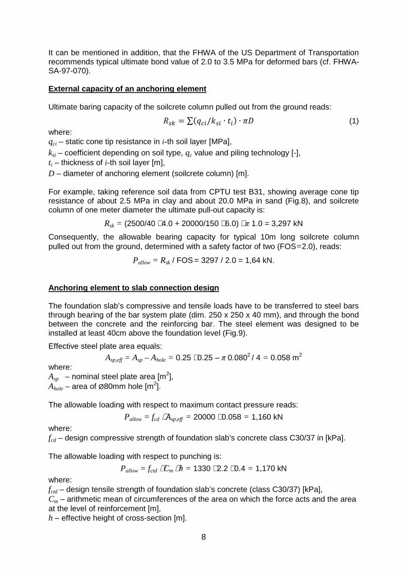
It can be mentioned in addition, that the FHWA of the US Department of Transportation recommends typical ultimate bond value of 2.0 to 3.5 MPa for deformed bars (cf. FHWA-SA-97-070). External capacity of an anchoring element Ultimate baring capacity of the soilcrete column pulled out from the ground reads:
��� = ∑���/�� ∙ � ∙ �� (1)
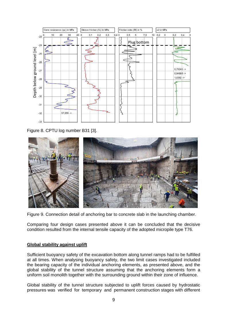
where: qci – static cone tip resistance in i-th soil layer [MPa], ksi – coefficient depending on soil type, qc value and piling technology [-], ti – thickness of i-th soil layer [m], D – diameter of anchoring element (soilcrete column) [m]. For example, taking reference soil data from CPTU test B31, showing average cone tip resistance of about 2.5 MPa in clay and about 20.0 MPa in sand (Fig.8), and soilcrete column of one meter diameter the ultimate pull-out capacity is:
Rsk = (2500/40 ⋅ 4.0 + 20000/150 ⋅ 6.0) ⋅ π 1.0 = 3,297 kN
Consequently, the allowable bearing capacity for typical 10m long soilcrete column pulled out from the ground, determined with a safety factor of two (FOS=2.0), reads:
Pallow = Rsk / FOS = 3297 / 2.0 = 1,64 kN. Anchoring element to slab connection design The foundation slab’s compressive and tensile loads have to be transferred to steel bars through bearing of the bar system plate (dim. 250 x 250 x 40 mm), and through the bond between the concrete and the reinforcing bar. The steel element was designed to be installed at least 40cm above the foundation level (Fig.9).
Effective steel plate area equals:
Asp,eff = Asp – Ahole = 0.25 ⋅ 0.25 – π 0.0802 / 4 = 0.058 m2
where: Asp – nominal steel plate area [m2], Ahole – area of Ø80mm hole [m2]. The allowable loading with respect to maximum contact pressure reads:
Pallow = fcd ⋅ Asp,eff = 20000 ⋅ 0.058 = 1,160 kN
where: fcd – design compressive strength of foundation slab’s concrete class C30/37 in [kPa]. The allowable loading with respect to punching is:
Pallow = fctd ⋅ Cm ⋅ h = 1330 ⋅ 2.2 ⋅ 0.4 = 1,170 kN
where: fctd – design tensile strength of foundation slab’s concrete (class C30/37) [kPa], Cm – arithmetic mean of circumferences of the area on which the force acts and the area at the level of reinforcement [m], h – effective height of cross-section [m].
9
Figure 8. CPTU log number B31 [3].
Figure 9. Connection detail of anchoring bar to concrete slab in the launching chamber. Comparing four design cases presented above it can be concluded that the decisive condition resulted from the internal tensile capacity of the adopted micropile type T76. Global stability against uplift Sufficient buoyancy safety of the excavation bottom along tunnel ramps had to be fulfilled at all times. When analysing buoyancy safety, the two limit cases investigated included the bearing capacity of the individual anchoring elements, as presented above, and the global stability of the tunnel structure assuming that the anchoring elements form a uniform soil monolith together with the surrounding ground within their zone of influence. Global stability of the tunnel structure subjected to uplift forces caused by hydrostatic pressures was verified for temporary and permanent construction stages with different
Plug bottom
De
pth
be
low
gro
un
d l
ev
el [m
]
10
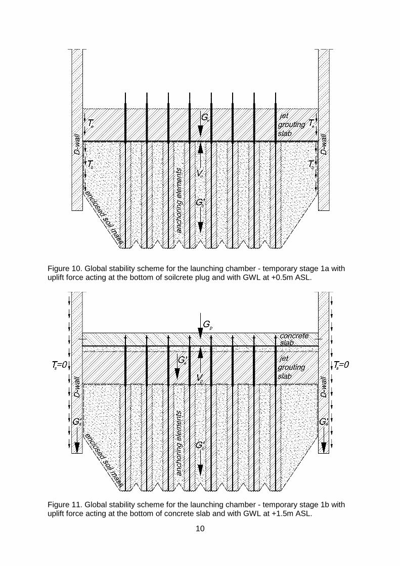
Figure 10. Global stability scheme for the launching chamber - temporary stage 1a with uplift force acting at the bottom of soilcrete plug and with GWL at +0.5m ASL.
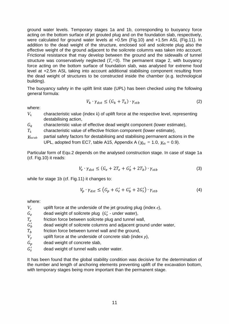
Figure 11. Global stability scheme for the launching chamber - temporary stage 1b with uplift force acting at the bottom of concrete slab and with GWL at +1.5m ASL.
11
ground water levels. Temporary stages 1a and 1b, corresponding to buoyancy force acting on the bottom surface of jet grouted plug and on the foundation slab, respectively, were calculated for ground water levels at +0.5m (Fig.10) and +1.5m ASL (Fig.11). In addition to the dead weight of the structure, enclosed soil and soilcrete plug also the effective weight of the ground adjacent to the soilcrete columns was taken into account. Frictional resistance that may develop between the ground and the sidewalls of tunnel structure was conservatively neglected (Ts=0). The permanent stage 2, with buoyancy force acting on the bottom surface of foundation slab, was analysed for extreme food level at +2.5m ASL taking into account additional stabilising component resulting from the dead weight of structures to be constructed inside the chamber (e.g. technological building).
The buoyancy safety in the uplift limit state (UPL) has been checked using the following general formula:
�� ∙ ���� ≤ ��� + ��� ∙ ���� (2)
where: Vk characteristic value (index k) of uplift force at the respective level, representing
destabilising action, �� characteristic value of effective dead weight component (lower estimate), Tk characteristic value of effective friction component (lower estimate), γdst/stb partial safety factors for destabilising and stabilising permanent actions in the
UPL, adopted from EC7, table A15, Appendix A (γdst = 1.0, γstb = 0.9). Particular form of Equ.2 depends on the analysed construction stage. In case of stage 1a (cf. Fig.10) it reads:
�� ∙ ���� ≤ ��� + 2�� + ��� + 2��� ∙ ���� (3)
while for stage 1b (cf. Fig.11) it changes to:
�� ∙ ���� ≤ ��� + ��� + ��� + 2���� ∙ ���� (4)
where: Ve uplift force at the underside of the jet grouting plug (index e), �� dead weight of soilcrete plug (��� - under water), �� friction force between soilcrete plug and tunnel wall, ��� dead weight of soilcrete columns and adjacent ground under water,
�� friction force between tunnel wall and the ground, Vp uplift force at the underside of concrete slab (index p), �� dead weight of concrete slab, ��� dead weight of tunnel walls under water. It has been found that the global stability condition was decisive for the determination of the number and length of anchoring elements preventing uplift of the excavation bottom, with temporary stages being more important than the permanent stage.

12
CONCLUSIONS The project involved construction of deep and large excavations for tunnel ramps and two TBM chambers as well as working with high groundwater levels and some challenging ground conditions. The adopted design is the result of geotechnical contractor’s proposal to move from working underwater to a dry operation to cut construction time and reduce costs.
The complete design was checked using several numerical analyses and the displacements anticipated were in line with the predictions. Special attention was paid to the impact and influence of the phasing of the work with different water levels at each stage of the excavation. Quality control was also a prime focus, and most of techniques were trialled before work on the main construction started. All this information was fed back into the design. The scope of QA/QC program included:
• additional soil investigations before works, • installation of trial jet grouted columns to check the diameters that could be
achieved at large depth and soilcrete strength based on wet grab and core samples,
• permeability tests (laboratory), • pull-out tests of anchoring rods to verify tensile capacity and bond stress, • verification of ground conditions during execution, • positioning control system utilising local GPS, • verticality checks of soilcrete columns using inclinometers, • DA and inspection of columns’ overlapping, • permanent control of all materials (steel, cement, concrete), • geodetic survey of diaphragm walls during excavation, • inclinometer readings in diaphragm walls, • monitoring of steel struts (internal forces, temperature), • heave warning system of soilcrete plug and micropiles, • groundwater levels (inside and outside excavations) and pumped volume.
A novel aspect was a combined use of anchored soilcrete plugs in the TBM chambers acting as structural and water tight elements. In case of the launching chamber the location of soilcrete plug just below the excavation bottom contributed to significant reduction of bending moments and horizontal deformations of diaphragm walls, and consequently to cost savings.
REFERENCES
[1] Design documentation in Polish (Projekt Wykonawczy „Połączenie Portu Lotniczego z Portem Morskim Gdańsk – Trasa Słowackiego” Zadanie IV. Odcinek Węzeł Marynarki Polskiej - Węzeł KU Ujściu. Tunel pod Martwą Wisłą i Węzeł Marynarki Polskiej. EUROPROJEKT GDAŃSK Sp. z o.o. and SSF Ingenieure GmbH, Gdańsk, I/2011).
[2] Geotechnical report in Polish (Dokumentacja geologiczno-inżynierska dla ustalenia geotechnicznych warunków posadowienia projektowanego tunelu pod Martwą Wisłą w ciągu trasy Słowackiego w Gdańsku. GEOPROJEKT Szczecin Sp. z o.o. Szczecin, X/2010).
[3] Supplementary soil investigation in Polish (Sprawozdanie z badań geotechnicznych wykonanych na terenie budowy zlokalizowanej przy ulicy Kujawskiej i Marynarki Polskiej w Gdańsku. GEOTEKO Sp. z o.o., Warszawa, V/2012).