topical review ferromagnetic enhanced inductive plasma …
TRANSCRIPT

IOP PUBLISHING JOURNAL OF PHYSICS D: APPLIED PHYSICS
J. Phys. D: Appl. Phys. 46 (2013) 283001 (23pp) doi:10.1088/0022-3727/46/28/283001
TOPICAL REVIEW
Ferromagnetic enhanced inductiveplasma sourcesValery Godyak
RF Plasma Consulting and University of Michigan Brookline, MA, USA
E-mail: [email protected]
Received 11 March 2013, in final form 26 April 2013Published 25 June 2013Online at stacks.iop.org/JPhysD/46/283001
AbstractThe subject of this paper is the review of inductively coupled plasma (ICP) sources enhancedwith ferromagnetic cores, FMICP, found in various applications, including plasma fusion,space propulsion, light sources, plasma chemistry and plasma processing of materials. Thehistory of FMICP, early attempts for their realization, some recent developments and examplesof successful FMICP devices are given here. A comparative study of FMICPs withconventional ICPs demonstrates their certain advantages in power transfer efficiency, powerfactor and their ability to operate without rf plasma potentials at low plasma densities and withsmall gaps, while effectively controlling plasma density profile.
(Some figures may appear in colour only in the online journal)
1. Introduction
Plasma source development has been one of the majorresearch activities in the low-temperature plasma communityfor several decades. It is primarily driven by the everlastingnew requirement for applications. It is generally believedthat different applications require different plasma properties,which is realized by the selection of different plasma sources.It is usually expected that the plasma property is inherentlycontrolled by the specific method of plasma generation. Infact, the plasma parameters and rates of plasma processingproduced by different plasma sources tend to be very similarto each other. This is because the plasma property is mainlycontrolled by the plasma geometry, gas composition, pressure,and power absorbed by the electrons [1, 2]. Therefore, fora given application, the most important features of a plasmasource affecting the plasma processes are the characteristicsof the boundary sheaths, plasma uniformity and the powerdelivering efficiency. In addition, the source should be ableto operate over a wide range of power and gas composition.
Taking the application in microelectronics industry as anexample, in the past few decades, a great variety of plasmasources has been considered for large scale semiconductormanufacturing. The main rf plasma sources under explorationhave been the capacitively coupled plasmas (CCPs), includingvery high frequency CCPs (VHFCCPs), inductively coupledplasmas (ICPs), including ICPs enhanced by a ferromagnetic
core, helicons, electron cyclotron resonance (ECR) and surfacewave (SW) plasmas [3, 4].
However, some of these sources suffer from some inherentdisadvantages, which severely limit their performances inmodern state-of-the-art applications. In the case of CCPsdriven by 13.56 MHz, the major problem is the inability togenerate high plasma densities at low gas pressures, and athigh rf powers, they are mostly spent on ion acceleration ratherthan plasma generation. Although ICPs are used in manyapplications with high density plasmas, there are fundamentalproblems and drawbacks in their implementation for large-scale plasma processing systems. The low power factor ofICP antenna coil loaded with plasma (Cosϕ � 1) requires aresonant-matching network, and leads to relatively high powerlosses in the coil and the matching network. This diminishesthe ICP power transfer efficiency and prevents ICP operationat low plasma density. Due to high coil voltage (reaching a fewkV), an essential capacitive coupling exists between the coiland plasma. As a result, a considerable rf sheath develops onthe plasma side of the window that separates coil and plasmawhich leads to intensive ion bombardment causing windowerosion and plasma contamination. A transmission line effectdeveloping along the ICP coil may also cause significantdeterioration of plasma uniformity over the processing surface.Both capacitive coupling and the transmission line effectbecome growing problems for ICP with large processing areas,high power and high driving frequencies.
0022-3727/13/283001+23$33.00 1 © 2013 IOP Publishing Ltd Printed in the UK & the USA

J. Phys. D: Appl. Phys. 46 (2013) 283001 Topical Review
Even for VHFCCPs, which are today’s mainstreamapproach for plasma etching reactors), there are somefundamental problems associated with the electromagneticnature of the VHF field, as revealed by scientists and engineersin both industry and research laboratories. The problems aredue to the finite skin depth (comparable to the plasma gap)or/and the standing wave effect [5–8]. They cause considerableplasma non-uniformity, which will become more severe forhigher operating frequencies, higher plasma densities andlarger wafer sizes. Furthermore, at very high frequencies,in a typical for CCP planar electrode structure, the inductivecoupling may prevail over the capacitive coupling [7]. At veryhigh frequency, various electromagnetic resonant modes mayoccur, depending on the rf frequency, the plasma size andthe plasma density. In this case, VHFCCPs’ operation maybecome unstable and uncontrollable due to mode jumping.From the production cost point of view, VHF rf generatorsand matching-tuning networks are expensive and have lowpower efficiency. For these reasons, it is my opinion thatVHFCCP reactors have no future for 450 mm wafer or largepanel processing.
In order to overcome the above-mentioned problems andto satisfy the requirement for uniform processing of largewafers with high speed, the following two design conceptshave been proposed: (1) a low-frequency ICP enhanced by aferromagnetic core (FMICP) [9–12] and (2) an ICP havingmultiple antennas to realize distributed rf excitations [13–15].The first design concept has been inspired by the extensiveresearch experience in the lighting industry. In fact, all existingcommercial rf light sources are essentially low-frequency ICPswith ferromagnetic cores and are operated with extremelyhigh efficiency [16]. However, many existing commercialICP reactors for plasma processing are far from an optimaldesign and performance, and recent proposals (mainly inthe patent literature) for their improvement by application offerromagnetic cores did not bring any new viable ICP design.
A great number of books and reviews have been devotedto ICP basic properties, their physics and engineering[1–4, 16–24]. The subject of this paper is a review of ICPsenhanced with ferromagnetic cores, FMICPs, their history,some recent proposals, and some successful realizations. Newunpublished results by the author are also included.
The structure of the review is as follows. In section 2, weconsider the FMICP applications in fusion, lighting and plasmachemistry which demonstrate their advantages over traditionalICPs. A detailed comparative study of ICP and FMICP isgiven in section 3. In section 4, we analyse some recentlyproposed FMICP sources for large scale plasma processing.In section 5 we consider an advanced distributed FMICP witha controllable plasma profile. FMICPs with immersed rfcouplers, some applications and specifics of FMICP operationin pulse mode are given in section 6. Concluding remarks aregiven at the end of the paper.
2. Some FMICP applications
In 1936, Bethenod and Claude [25] were the first to propose anenhanced ICP by placing a ferromagnetic core with a coil inside
Figure 1. The first proposal of ICP with ferromagnetic core forlighting.
a spherical discharge glass vessel, as shown in figure 1. It waslong before the development of contemporary technology forgas discharge light production, fluorescent and high intensitydischarge (HID at high gas pressure). Half a century later,the first rf fluorescent lamp based on the proposal in [25] wasunveiled by Philips [26]. This became possible because of theprogress in semiconductor electronics and power switchingtechnology, which led to efficient and cost effective rf powersources.
In the late 1950s, the very first practical application ofFMICP was implemented in the toroidal plasma fusion devices(similar to today’s tokamaks) for initial gas breakdown andits ionization followed by plasma heating and confinement.Such an approach is used in today’s toroidal fusion facilitiessuch as International Thermonuclear Experimental Reactor,ITER [27]. In those devices an ICP is maintained insidea metal toroidal chamber by electromotive force created bya time variable magnetic flux in the transformer steel core(magnetic circuit) that embraces the toroidal chamber, asshown in figure 2. The magnetic flux in the ferromagnetic coreat low frequency (just a few periods of decaying oscillations)is created by discharging a powerful battery of capacitors tothe primary winding of such a transformer. The stainlesssteel toroidal chamber wall with its thickness less than its skindepths, or with dielectric insertions in the chamber are used toensure the magnetic field penetration into the metal dischargechamber.
2

J. Phys. D: Appl. Phys. 46 (2013) 283001 Topical Review
Toroidal plasma
Transformer steel core
Figure 2. First application of ICP with ferromagnetic core in thetoroidal plasma for fusion.
Figure 3. Endura/Icetron® powerful rf fluorescent lamps system.
More recently, different kinds of FMICP have beenutilized in rf light sources [28–31] and in plasma-chemicalreactors for generation of active processing gases and oxidation[32, 33]. In those FMICPs with rf power ranging between 20 Wand 200 kW, the frequency between a few kHz and a few MHzat gas pressure from a fraction of mTorr to atmospheric pressurehas been used. Let us consider in more detail some FMICPdevices to demonstrate advantages of using ferromagneticcores.
2.1. FMICP for light generation
Following the concept of toroidal plasma transformers forfusion, Bell [28] built an rf ion laser and Andersen [29] builtan rf fluorescent lamp by closing the glass discharge tube uponitself forming a racetrack shape and surrounding it by toroidalferrite cores with primary winding fed by an rf generator.However, those light sources showed poor performance, andthe concept of toroidal plasma transformers was thereforenot able to compete with traditional solution for lightingapplications.
Just a quarter of a century later, it was shown [30]that, with optimal design, such an rf lamp can not onlybecome a competitive product, but can exceed the performanceof conventional (i.e. with electrodes) fluorescent lamps inefficiency and total light output. We are not aware of similardevelopments in lasers.
Developed at Osram Sylvania [30, 35], the powerfulelectrodeless fluorescent lamp Endura/Icetron® and its
~
RF discharge currentFerrite core
Ferrite core
Toroidal glass tube
RF power source
Figure 4. Schematic of Endura/Icetron® rf lamp.
Figure 5. QL rf fluorescent lamps of 165, 85 and 55 W.
schematic are shown in figures 3 and 4, respectively. Aracetrack/toroidal shape glass tube having ID 5 cm withdischarge path about 80 cm is filled with argon or kryptongas at a pressure of 0.3 Torr with mercury vapour at about7 mTorr. The tube is covered inside with a phosphor convertingthe mercury resonance UV radiation into visible light. Theelectromotive force that maintains the plasma is induced bytwo ferrite toroidal cores with their primary winding connectedto a high efficiency (90%) rf power converter (ballast) fed fromthe line voltage of 120 or 220 V.
The lamp operates at 250 kHz with consumed ac powerof 150 and 100 W producing 12 000 and 8000 lm, respectively.At the discharge current of 6 A, the plasma density on thedischarge axis of 150 W lamp is 1.3 × 1012 cm−3 and theelectron temperature is 1 eV. The unique feature of this FMICPlamp is the extremely high power transfer efficiency η, thatis the ratio of the rf power absorbed by plasma to thatdelivered to ferromagnetic couplers from the rf source. The150 W Endura/Icetron lamp has the record high power transferefficiency (η = 98%), the highest among commercial rf plasmasources ever made. At η = 98%, only 2% of rf power is lost inthe ferrite couplers. Among others industrial FMICP devices,Endura/Icetron lamp has documented records of thoroughexperimental and theoretical studies of its light, electrical andplasma characteristics (including electron energy distributionfunctions (EEDFs) measurement) in both CW and pulse modes[35–38].
Another successful product based on FMICP is the PhilipsQL rf lamp [26] shown in figures 5 and 6. The lamp topologyis the same as that of the Bethenod lamp [25], having acoupler (antenna) with ferrite rod immersed inside the lamp
3

J. Phys. D: Appl. Phys. 46 (2013) 283001 Topical Review
Figure 6. Schematic of QL rf fluorescent lamp.
Figure 7. Dura-One® compact rf fluorescent lamps.
bulb. Placing the ferrite antenna inside the plasma increasesits coupling to plasma and prevents the obstruction of thegenerated light by the coupler set outside the lamp. The QLlamp operates at 2.65 MHz with an ac power of 85 W and lightoutput of 6000 lm with power transfer efficiency η = 94%.Note that the fraction of rf power lost in the couplers in theconsidered above rf lamps is an order of magnitude lower thanthat in conventional industrial ICPs for plasma processing ofmaterials.
Later, the Genura® of General Electric [39] and the Dura-One® of Osram Sylvania [40] have both been developedas compact versions of rf fluorescent lamps suitable forreplacement of incandescent and electroded fluorescent lamps.Two versions of the electromagnetic interference free compactrf lamp Dura-One are shown in figures 7 and 8. Bothlamps have topologies similar to the QL lamp and operateat 2.65 MHz with ac powers of 20 W (A-shape) and 23 W
Figure 8. X-ray image of Dura-One lamp prototype.
(reflector type). Both versions of the lamp have light efficiencyfour times higher and longevity 15 times longer than those ofincandescent bulbs. The power transfer efficiency in theselamps is over 90%.
Today, there is a great variety of commercial rflight sources utilizing FMICP and following the topologiesconsidered above. Compact fluorescent rf lamps in therange 15–25 W suitable for replacement of low-efficiencyand short-lasted incandescent bulbs as well as very high-power rf fluorescent lamps (up to 1 kW) have been developedand commercialized by many US, European and Far Eastcompanies. The elimination of electrodes that are necessary inconventional gas discharge light sources allowed for flexibilityin lamp shapes and for prolongation of lamp life up to100 000 h.
2.2. Transformer coupled toroidal discharge TCTD
A variety of high power (0.1–200 kW) plasma sourcesbased on FMICP in toroidal metal chambers (Tokamak typedischarges, or Transformer Coupled Toroidal Discharges,TCTD) operating at relatively low frequencies (10–580 KHz),in the gas pressure range between 10−4 Tor up to atmosphericpressure, have been developed for laboratory study andmanufactured for different industrial applications as describedin [32, 33, 41–46].
A review of the transformer coupled toroidal dischargesTCTD developed in Russia has been recently published in[46]. Particularly, a detailed study of electrical, chemical andthermal characteristics of these devices has been considered inapplications for plasma-chemical synthesis of NO and O3, aswell as for UV and visible light generation.
4

J. Phys. D: Appl. Phys. 46 (2013) 283001 Topical Review
Figure 9. Powerful TCTD plasmatron driven at 10 kHz.
Figure 10. Schematic of a powerful TCDT experiment. 1—primarywinding; 2—sections of magnetic core; 3—discharge chamber;4—heat exchanger; 5—main gas feed; 6—secondary gas feed;7—probe no 1; 8—probe no 2; 9—probe no 3;10—spectrophotometer; 11—mass-spectrometer.
An example of such a device is a high-power plasmareactor operating at 10 kHz with maximal power of 180 kWthat is shown in figures 9 and 10. High-density plasmasin noble and molecular gases were maintained in awater-cooled metal toroidal chamber consisting of severalinsulated sections and having inner diameter of 8–10 cmand perimeter of 180 cm. The ferromagnetic core consistedof eight-sections made of transformer steel sheet woundinto toroidal shape having 42 cm OD, 16 cm ID and 7 cmheight.
A similar TCTD, Astron® [33] operating as a remoteplasma source for production of chemically active gaseshas been developed and manufactured by MKS. In thisreactor, high density plasma in a molecular gas flow ismaintained in a sectioned toroidal metal chamber encircledwith closed-path ferrite cores with primary winding driven at400 kHz with a few kW of rf power. Such a device usuallydissociates molecular gases to obtain chemically active speciesfor cleaning plasma processing chambers and/or treating ofmaterials.
Nearly fully ionized pulse plasma has been obtained inpulse FMICP energized with a toroidal ferromagnetic inductor
immersed in the plasma chamber [47]. The six-turn primarywinding of the inductor was switched by a thyratron to a pulseforming network. The induced plasma current in the chamberfilled with xenon gas at a pressure range (1.0–3.3)×10−4 Torrreached up to 300 A during the 70–200 µs pulse, producingplasma density up to 1013 cm−3. The maximal power transferefficiency in this device reached 90%.
The applications and devices considered above demon-strate the viability and attractive features of FMICPs, suchas high efficiency and ability to operate at significantlylower driving frequencies than those usually used in plasmaprocessing equipment at 13.56 MHz. Utilization of lowfrequencies for plasma generation allows for more efficientand less expensive power sources and facilitates the powermanagement. Moreover, the direct drive (without rf or hfgenerator) of FMICP from the power line at 60 Hz has beendemonstrated in laboratory experiment by Eckert [48].
3. Comparative study of ICP and FMICP sources
The FMICPs considered above do not give direct answers tothe following question: what would be the performance ofthose ICP devices without ferromagnetic cores? Moreover,is there a quantitative characterization of the merit for addinga ferromagnetic core? The answers to those questions areextremely important for the development of new plasmasources. Those answers, however, are not trivial. It is not easyto produce (or realistically model) plasma sources with andwithout ferromagnetic core, which have the same geometry,gas pressure, frequency and discharge power, and thus, havethe same plasma parameters. It is apparent that each of thementioned characteristics (and all of them together) wouldaffect the plasma source performance.
3.1. The difference between conventional transformer andconventional ICP
In spite of common operational principles, there arefundamental differences in electrical properties of aconventional ac transformer and a conventional rf ICP. Due to astrong coupling between primary and secondary circuits (k ≈1) provided by a ferromagnetic core with closed magnetic pathand high permeability µ ≈ 104, a conventional transformerbehaves very closely to an ideal transformer, for which
k = 1, Q1 = ωLs/R12 → 0, Cosφ = 1,
V1/V2 = I2/I1 = N1/N2, R12 = R2(N1/N2)2.
Here k is the coupling coefficient between primary andsecondary circuits of the transformer, k = M(L0L2)
−1/2, M
is the mutual inductance between the primary coil inductanceL0 and the magnetic inductance L2 of the plasma currentpath (defined by its geometry), Q1 is the Q-factor of theprimary circuit, Ls is the leakage inductance of the primarywinding, R12 is the resistance R2 of the secondary circuittransformed to the primary circuit, V1, V2, I1, I2, N1 and N2
are, correspondingly, the voltages, currents and numbers ofturns of the primary and secondary windings. Note that Q1
5

J. Phys. D: Appl. Phys. 46 (2013) 283001 Topical Review
Figure 11. Magnetic line structure in a conventional transformer(a), and in a conventional ICP (b).
defines the ICP power factor Cosφ = (1 + Q21)
−1/2, and forQ1 � 1, Cosφ = Q−1
1 .In contrast, in a conventional ICP operating in rf frequency
range with no core and loose coupling between coupler coil andplasma (N2 = 1, µ = 1, R2 = Rp):
k = 0.2–0.7, Q1 = ωLs/R12 � 1, V1/V2 �= N1
and R12 �= RpN21 .
Due to large Q-factor of the primary coil loaded with plasma,a resonant-matching network is needed to compensate thecoupler coil reactance ωLs ≈ ωL0, and to effectively transferrf power from an rf generator to the antenna coil. The largeresonant coil current I1 (in the range of tens of ampere) andcoil voltage V1 (in the range of a few kV) in the typical plasmaprocessing equipment lead to a considerable power loss in boththe coil and the matching network. For this reason, the powertransfer efficiency of a conventional ICP is essentially lowerthan that of the conventional ac transformer. Recall that theefficiency η = 98% of Endura/Icetron rf lamp mentionedin section 2.1 is higher than the efficiency of a regular actransformer of similar power.
Figure 11 illustrates the principal difference betweena regular transformer and a conventional ICP. In a regulartransformer, due to a closed ferromagnetic core with highpermeability, practically all the magnetic flux, created by theprimary winding, is inside the core and crosses the secondarywinding, and vice versa. As a result, the transformer is veryclose to an ideal transformer with the secondary load Z2 beingtransformed to the primary circuit merely as Z2(N1/N2)
2.In the conventional ICP, the magnetic flux, created by the
primary coil, spreads out, and its significant portion does notembrace the nearby plasma, but instead closes upon itself in thespace between the plasma and the coil. Similarly, the magneticflux created by the plasma current is loosely coupled with theICP inductor coil. As a result, the ICP coupling coefficient k isessentially less than 1, making the conventional ICP a merelypoorly performing transformer.
3.2. Power transfer efficiency
The power transfer efficiency η is the ratio of rf power Pp
absorbed by plasma to the power delivered to the coupler coilP , η = Pp/P = (1 + τ)−1, where τ = Pc/Pp is the relative
coil loss and Pc is the power loss in the coupling inductorPc = P − Pp. An analysis of ICP system that accountsfor coupler coil electrical parameters showed that the relativecoupler power loss of the ICP system τ is given by the followingexpression [49]:
τ = Pc/Pp = (k2Q0Qp)−1[(Qp + ω/νeff)
2 + 1],
where Q0 = wL0/Rc is the Q-factor of the primary coil(coupler) with no plasma, Qp = ωL2/Rp ∝ Pp, Rc is thecoupler resistance, Rp is the plasma resistance, and νeff is theeffective electron collision frequency which accounts for bothcollisional and stochastic (collisionless) rf power absorption[50–52].
Note that in general, the coupler power loss Pc is definedby the power lost in the ferromagnetic core material Pf andthe power Pw lost due to the winding rf resistance Rw, thusPc = Pf + Pw. It follows from the expression above thatτ ∝ (k2Q0)
−1. Hence, to minimize coupler loss, one has toincrease the coupling coefficient k and its Q-factor Q0, andto operate at the lowest possible rf frequency (ω < νeff). Atrelatively low discharge power, when the plasma Q-factor isQp = ωL2/Rp < (1 + ω2/ν2
eff)1/2, the relative coil loss is
dropping with increase in Qp. Since Rp ∝ P −1p , it follows that
Qp ∝ Pp, and the relative coil loss is falling with the dischargepower. On the other hand, an increase in plasma resistanceRp leads to an increase in the relative coupler loss. For thosereasons the conventional industrial ICP reactors working withmolecular and electronegative gases (having intrinsically highplasma resistivity) cannot operate in the ICP mode at relativelylow plasma density.
The limitation on the minimal rf power (and thus, plasmadensity) at which stable ICP operation in inductive mode ispossible is defined by the power lost in the coupler Pc. Anempirically found rough criterion of ICP stability is Pc < Pp,or η > 1/2, although, an ICP operation may be possible atPp < Pc (but not at Pp � Pc) when the coupler/matchernetwork has some ballasting feature.
In general, the coupler power loss is
Pc = I 21 Rw + Aζ(B, F ) = Pw(I1) + Pf(V1),
where Rw is the coil rf resistance, A is the ferromagneticcore volume, ζ = ζ(B, F ) is the specific power loss offerromagnetic material, B is the average over the volumemagnetic induction in the core and F = ω/2π is the cyclefrequency. Since the coupler voltage V1 ∝ BF , the powerloss in the core is defined by the coupler voltage, Pf = Pf(V1),while the power loss in the coil is defined by the coupler current,Pw = Pw(I1).
According to ionization and electron energy balance ofsteady-state gas discharge plasma [4], the plasma sustainingrms electric field E is
E2 = 3Temξνeff(1 + ω2/ν2eff)/2e ≈ E2
dc(1 + ω2/ν2eff),
which is practically independent of the discharge power andthe plasma density (what is nearly proportional to the dischargepower Pp). Here, Te is the electron temperature in energy
6

J. Phys. D: Appl. Phys. 46 (2013) 283001 Topical Review
units (eV), −e and m are the electron charge and its mass, ξ
is the frequency of electron energy loss due to different kindsof collisions and electron escape to the wall and Edc is theelectric field rms in the self-sustained dc current plasma. Dueto effects of the two-step ionization via excited states, and thedependence of the electron energy distribution on the plasmadensity, the electric field is slowly dropping with rf power(a well know feature of negative volt–ampere characteristicof gas discharge plasma).
Since the coupler rf current I1 is proportional to the electricfield at the plasma boundary (E ∝ I1ω), the power lost in thecoupler coil is Pw ∝ E2 ≈ E2
dc(1 + ω2/ν2eff). On the other
hand, the coupler voltage V1 that defines the core loss is alsoproportional toE, while the power loss in the corePf is growingwith the coupler voltage faster than quadratic. Particularly,for ferromagnetic cores in FMICP applications, Pf ∝ V k
1 ,with k being between 2.1 and 2.9, depending on the material,frequency, magnetic induction strength and temperature.
The consequence of the coupler loss correlation withthe plasma electric field (that is maximal at low plasmadensities) is that in negative molecular gases with high electricfields, typical in plasma processing, the coupler power loss isexcessively high. In such cases, the coupler loss needed tomaintain the plasma may exceed the power capability of theavailable rf power source, and the plasma cannot be sustained.This problem can be avoided using FMICP which considerablyreduces coupler power losses.
3.3. Effect of ferromagnetic core
The expression for the relative coil loss τ suggests a way toreduce the coupler loss by increasing the plasma Q-factor ∝ L2
using a high permeability (µ � 1) ferromagnetic core. Theintroduction of ferromagnetic core also increases the primaryinductance L0 and the coupling between the coupler andplasma. The increase in the coupler and plasma inductancesis defined by the effective permeability of the ferromagneticcore µeff = Lc\L0. An increase in primary coil inductance L0
reduces the primary current by a factor of µeff and reduces coilwire loss by a factor of (µeff)
2. Although an additional lossappears due to core loss, it can be made reasonably small with aproper choice of the core size, rf frequency and ferromagneticmaterial.
The core effective permeability µeff may be much smallerthan the ferromagnetic material permeability µ. For closedmagnetic path toroidal ferromagnetic cores with µ � 103 usedin TCTDs, the value of µeff is close to µ. For cylindrical rodswith µ � 20, the value of µeff ≈ 1 + 2lc/dc is practicallyindependent of µ; here lc and dc are the core length anddiameter. For a single wire or flat winding unilaterally coveredwith ferrite slate, µeff = 1.5–2.
The most effective way to increase ICP performance isto use a high permeability core with a closed magnetic path.In this case, µeff ≈ µ, the coupling coefficient is very closeto unity (k ∼= 1), and the FMICP acquires many features ofan ideal transformer. The possibility to drastically reducethe driving frequency (up to ac line frequency) is the mostremarkable feature of a FMICP with a closed ferromagnetic
No core Rod core Closed U-cores
Figure 12. ICP sources with different couplers.
core. Unfortunately, the toroidal discharge current path in suchFMICPs puts essential limitations on plasma configurations,thus limiting their applicability.
The performance comparison of three different ICP rflamps of system power of about 150 W, operating at differentfrequencies and having different rf field configurations, hasbeen reported in [31]. Three lamps were compared: theEndura/Icetron lamp with closed ferrite toroids, the QL®
lamp with an internal coil and ferrite rod and the QL bulbenergized by equatorial winding without a ferrite core, drivenat 0.25 MHz, 2.65 MHz and 10 MHz, respectively. It has beenfound that the relative coupler power loss τ for these lampscorresponded to 2.1%, 4.8% and 9.1% of the total systempower. This result clearly shows the advantages of usingferromagnetic cores, especially those with a closed magneticpath.
3.4. Experiment with ICP of different coupler structures
A detailed comparison of electrical parameters of ICP without acore and with different ferrite core configurations, but with thesame discharge geometry, the same rf field topology, and thesame driving frequency, has been carried out by this author andpartially published in [11]. The ICP electrical characteristicswere measured in a wide range of discharge powers Pp (thepower consumed by the plasma) that has been found as thedifference between the total power and the power lost in thecoupler. The ICP electrical characteristics were comparedfor the same plasma geometry and discharge power to obtainidentical plasmas for different couplers.
Three ICPs with different coupler cores were sustainedin a glass vessel formed by a spherical bulb (7.5 cm OD) andan inner tube (2.2 cm ID) housing the coupler. The vesselwas filled with krypton–mercury mixture (0.5 Torr/6 mTorr)typical of fluorescent light sources. The ICPs were drivenat 2.5 and 0.4 MHz with a 13-turn coil and different couplerconfigurations: with no core, with a ferrite rod core (lc =4.4 cm, dc = 1.85 cm, µ = 100 for 2.5 MHz and µ = 2000for 0.4 MHz) and with closed magnetic path formed by twoferrite U-cores of the same materials. In the discharge powerrange between 2.5 and 200 W, the volume average plasmaloading was between 0.015 and 1.2 W cm−3. The three ICPconfigurations with different couplers are shown in figure 12.The results of the measurement are presented in figures 13–18.
The coupler winding current I1 and voltage V1 measuredover a large range of discharge power, for three ICP
7

J. Phys. D: Appl. Phys. 46 (2013) 283001 Topical Review
0.1
1
10
1 10 100
coil
curr
ent (
A)
discharge power (W)
no core
rod core
U-core
2.5 MHz
Figure 13. Coupler coil current as a function of discharge power at2.5 MHz.
0
50
100
150
200
250
1 10 100
coil
volta
ge (
V)
discharge power (W)
no core
rod core
U-core
2.5 MHz
Figure 14. Coupler voltage as a function of discharge power at2.5 MHz.
configurations are shown in figures 13 and 14. As seen infigure 13, the introduction of the ferrite rode dramatically (µeff
times) reduces the coupler current. Even a larger reduction inthe coupler current occurs with the closed ferrite core. Atsmall discharge powers (i.e. low plasma density), the valuesof the coupler current tend to the magnetizing currents I0. Atlarge discharge powers (Pp � 100 W), the ICP sources withthe rod core and the closed core operate like a conventionaltransformer with the I1 � I0 when I1 ≈ Ip/N1, where Ip isthe plasma discharge path current.
The comparison of the coupler voltages, for different ICPconfigurations, given in figure 14, shows that introducing aferrite core reduces the needed coupler voltage to maintain thesame value of electromotive force (discharge voltage) in ICP.This is due to the increase in the coupling between the couplerand plasma. The fractions of the primary magnetic flux linkedto the plasma, for the air-core, rod core and U-core are 0.63;0.72 and nearly 1.
The falling of the coupler voltage with discharge power,seen in figure 14, reflects the negative I/V plasma discharge
0.01
0.1
1
1 10 100
rela
tive
pow
er lo
ss
discharge power (W)
rod
no core
U-core
2.5 MHz
Figure 15. Relative coupler power loss as a function of dischargepower at 2.5 MHz.
characteristic. On the other hand, the coupler voltage isgrowing at a large discharge power due to ballasting actionof the plasma inductance L2 and the leakage inductance Ls,which is the portion of the coupler inductance not coupledto the plasma. Those two inductances and their reactancesare practically independent of discharge power and plasmadensity, while plasma resistance is inversely proportional toplasma density and to discharge power. The resistive part ofthe plasma voltage stays nearly constant, while the voltage dueto leakage and plasma inductances grows proportionally to theplasma current. For this reason, the rise in the coupler voltagetakes place at the large discharge power.
A remarkable feature of FMICP is the dramaticreduction in the coupler loss compared with an ICP withoutferromagnetic core. The relative coupler power lossτ = Pc/Pp shown in figure 15 demonstrates an order ofmagnitude reduction in the coupler loss in the ICP withferromagnetic core. According to the above expression, τ
drops with discharge power (since Pp ∝ Qp), reaching itsminimum at ωL2 ≈ Rp ∝ E/Pp for sufficiently largedischarge powers. When a ferrite core is present, the increasein the plasma inductance L2 shifts the position of minimal τ toa lower discharge power, see more details in [49]. The relativeinductor loss in FMICP is an order of magnitude lower thanin the ICP with no ferrite core, and at Pp = 100 W, τ ≈ 1%.This is 10 times less than in the best helicon plasma sourcewhich is considered to be the most efficient plasma source.The measured lowest antenna loss in the helicon plasma foundin the literature is 10% [53].
Application of ferromagnetic core leads to a significantincrease in the loaded with plasma coupler power factor Cosφ,as shown in figure 16. In general, the power factor growswith µeff and with discharge power, reaching its maximum atωL2 ≈ Rp, which for a closed ferromagnetic core approachesunity. As the power grows further, Cosφ is dropping due to theincreasing role of the leakage and plasma inductances at largeplasma density.
A relatively high Cosφ in FMICP allows for a significantsimplification and for power loss reduction of the matchingnetwork, and eliminates the need for its resonant tuning. In
8

J. Phys. D: Appl. Phys. 46 (2013) 283001 Topical Review
0.01
0.1
1
1 10 100
pow
er fa
ctor
discharge power (W)
no core
rod core
U-core
2.5 MHz
Figure 16. Power factor as a function of discharge power at2.5 MHz.
Figure 17. Power lost in winding Pw and in ferrite core Pf at2.5 MHz.
fact, there is no need in a matching network at all for FMICPwith a closed magnetic path, when Cosφ ≈ 1, and the matchingcan be achieved just by a proper choice of turns of the couplerwinding.
Absolute power losses in the coupler winding Pw and inthe ferrite core Pf are shown in figure 17. The wire power lossPw = I 2
1 Rw remains around 10 W in all ranges of the dischargepower for the ICP without a ferrite core, while Pw is negligiblein the FMICP. Thus, at Pp = 10 W, the wire power loss Pw inthe FMICP is reduced 34 times for the rod core and 720 timesfor the closed core. Only at sufficiently large coupler currentsdoes the wire power loss become comparable to the core loss.
Similar experiments carried out at 400 kHz are illustratedin figures 18–20. They show an even more dramatic difference
0.1
1
10
1 10 100
coil
curr
ent (
A)
discharge power (W)
rod
long rod
U-core
0.4 MHz
Figure 18. Coupler coil current as a function of discharge power at400 kHz.
Figure 19. Power factor as a function of discharge power at400 kHz.
between FMICP and conventional ICP. Note that at 400 kHz,it was impossible to maintain an ICP without a ferromagneticcore in this experimental arrangement. In fact, it can be shownthat in order to maintain a 20 W ICP without a ferromagneticcore, about 40 A of coil current and 250 W of coil power lossare needed. Experiments at 400 kHz also have shown that themost efficient configuration of the coupler was the S-shapedlong core formed by two U-cores of which one was turnedat 180◦ around the discharge axis. In this case, the core lossreduction was due to a weakening of the magnetic flux at thecore ends, in contrast to a closed ferromagnetic core wherethe magnetic flux along the closed path remains essentiallyunchanged.
Figure 18 shows the coupler current as a function ofdischarge power and demonstrates a stronger current reductioncaused by the ferromagnetic core than the one found at2.5 MHz. This difference is caused by the core with µ = 2000instead of µ = 100 at 2.5 MHz. Similarly, the power factorgiven in figure 19 and the relative coupler power loss given infigure 20 are larger than those found at 2.5 MHz. Thus, the
9

J. Phys. D: Appl. Phys. 46 (2013) 283001 Topical Review
0.01
0.1
1
1 10 100
rela
tive
pow
er lo
ss
discharge power (W)
rodlong core
U-core
0.4 MHz
Figure 20. Relative coupler power loss as a function of dischargepower at 400 kHz.
Ferrite core
Quartz tube chamber
Two turn coupler coil
Ferrite core
Figure 21. Schematic diagram of the FMICP with side antennahaving ferromagnetic core.
power factor Cosφ is practically equal to 1 in the dischargepower range between 20 and 200 W for the closed U-core asseen in figure 19. At a maximal power of 200 W, the relativecoupler loss τ (shown in figure 20) for the closed U-core aswell as for the long rod core is about 0.5%.
Comparing the Cosφ and τ values obtained in the 100 WFMICP at 400 kHz with the corresponding values in the 100 WICP at 2.5 MHz without a core, we see a 7.5 times and a 20times improvement.
4. FMICPs for plasma processing
In this section, we consider a variety of recently proposedschemes aimed to improve ICP mainly for plasma processingapplications. In particular, we will discuss specific featuresand limitations of different designs of FMICP for large scaleprocessing.
4.1. FMICPs with open ferrite core
The effect of adding a ferrite core to the coil coupler (antenna)in a cylindrical ICP driven at 13.56 MHz has been reportedin [34]. A qualitative FMICP diagram of this experiment isshown in figure 21. A two-turn coil around the dischargechamber formed with 10 cm OD Quartz tube was covered witha ferromagnetic (µ = 80) belt as shown in figure 21. Electrical
25 mm thick window 2 turn coil
45 mm thick ferromagnetic material
Figure 22. Schematic diagram of the FMICP with top antennahaving ferromagnetic core.
and plasma parameters of this ICP with and without ferrite corewere measured in the range of applied power between 25 and500 W, at argon pressures between 5 and 20 mTorr.
The addition of ferrite core resulted in about 1.5 timereduction of the coil current and about 10% rise in both thecoupling coefficient and the plasma density. The expectednearly two-fold reduction in the coil loss due to the currentreduction was offset with the additional loss in the ferritecore. The reasons for a marginal improvement in the ICPcharacteristics with addition of the ferromagnetic core in thisexperiment are typical for other published works on FMICPand will be discussed later.
Electrical and plasma characteristics of an ICP with a topflat window and the coupler formed with a coil embedded ina ferromagnetic plate, as shown in figure 22, were reportedin [9, 12]. The ICP parameters were measured at a drivingfrequency of 13.56 MHz in the input power range between100 and 700 W, with and without the ferromagnetic core.Similarly to the results found in [34], the coil current wasmeasured to be about 50% less than without the core. Thereduction in the coil current should reduce the power loss inthe coil and in the matching network, but additional powerloss in the ferromagnetic core may offset this gain and evenincrease the total coupler loss. According to [9] ‘Nevertheless,reliable measurements of the power transfer efficiency havenot been possible because of the poor measurement accuracyclose to the 90◦-shift phase’. However, given the fact of thethick window and of the very high power loss in the usedferromagnetic material at 13.56 MHz, one could expect thepower transfer efficiency to be no better (or even worse) thanwithout a ferromagnetic core.
The reduction in the window thickness to 4 mm (insteadof 25 mm) resulted in a significant rise in the ICP efficiency,but the coupler arrangement had to be placed into a vacuumdischarge chamber, to preserve the mechanical integrity of thewindow. Indirect efficiency assessment obtained by comparingthe ion current with the probe installed in the chamber showedthat (at the same input power) the ion current in FMICP witha 4 mm window is about four times larger than in the ICP with25 mm window. A nearly similar result has been obtainedin [12] for a large area (1×1 m2) FMICP with embedded coilsand a thin window. However, to what extent this difference isattributed to the thin window or/and to the ferromagnetic coreremains unclear.
Another scheme of FMICP for large area processing hasbeen proposed and studied in [54, 55]. A typical device
10

J. Phys. D: Appl. Phys. 46 (2013) 283001 Topical Review
Langmuir Probe Array Substrate
Ferromagnetic core
Internal antenna
Internal Antenna Quartz tube Ferromagnetic core
240mm
RF Source
2.3 m
0.74 m
Figure 23. FMICP with immersed U-shaped antenna partly coveredwith ferromagnetic core.
used in those works is shown in figure 23. An immersed(internal) U-shaped antenna is covered with a quartz tube, thenwith a half-tube (inversed gutter) ferrite shield, and the entirestructure is encapsulated in another quartz tube to protect theferrite shield from chemical interaction with plasma.
Conceptually this approach is similar to the one usedin [9, 12, 34]. The main idea was to reduce the magneticresistance of the magnetic field path around the antennaconductor, in order to enhance the magnetic induction betweenferrite poles in the gap facing the plasma. But using a thinwall quartz tube (instead of a thin large window in [9, 12])to separate the coupler from the plasma simplifies the antennaconstruction and provides a more reliable mechanical integrity.
A detailed study of the electrical and plasma parametersfor this kind of FMICP operating at 13.56 and 2 MHz, with andwithout a ferrite core, was performed in [54, 55]. The antennacurrent, voltage and power factor measured at 13.56 MHz andat argon pressure of 20 mTorr are shown in figure 24. Asshown in figure 24, the application of a ferromagnetic coreresulted in practically no change in the coupler voltage, inabout 50% reduction in the coupler current and in doubling ofthe coupler power factor. The latter is due to enhancements inthe coupling coefficient and in the additional power loss in theferrite material of the antenna covered with the ferrite shield.
The reduction in the driving frequency to 2 MHz inthis immersed coupler FMICP resulted in about three timesreduction in the antenna power loss as shown in figure 25.
Figure 24. Voltage, current and power factor measured with andwithout ferromagnetic core.
Figure 25. Comparison of the coupler voltage and coupler loss at13.56 and 2 MHz in immersed FMICP.
This reduction is mainly due to reduced power loss in the ferriteshield which had an excessive loss at 13.56 MHz. Reductionin the driving frequency also resulted in the lowering of theplasma rf potential as shown in figures 26.
The three considered schemes of ICPs with ferromagneticcore demonstrate some marginal improvement in ICP sourceelectrical and plasma characteristics. However, the modest 1.5times reductions in the coupler current and some increase in theplasma density hardly justify the application of a ferromagneticcore in the ICPs built according to these schemes.
The common problem of those FMICP operating at13.56 MHz is the use of ferromagnetic materials which causesexcessive losses at this frequency, offsetting the expectedpositive effects of using a ferromagnetic core. The differencein ICP parameters measured at 13.56 MHz and in FMICPat 2 MHz may be mostly due to the combined effect ofthe difference in frequencies, and of the application of aferromagnetic core. The other common and significantproblem in the FMICP embodiments of [9, 12, 34, 54, 55] is thevery small distance between the coupler poles compared withthe distance to the plasma. That makes the majority of the rfmagnetic flux to be closed in the window rather to embrace thenearby plasma (as shown in figure 27) and has a consequenceof poor coupling. The resolution of this problem will be givenlater.
11

J. Phys. D: Appl. Phys. 46 (2013) 283001 Topical Review
0 100 200 300 400 500 600
12
15
18
21
24
2713.56MHz
5mTorr
Pla
sma
Pot
entia
l (V
)
Delivered Power (W)
13.56MHz + Ferrite module 5mTorr
2MHz+Ferrite module 5mTorr
Figure 26. Plasma potentials without and with core at 13.56 and at2 MHz.
Figure 27. Ineffective FMICP couplers designs.
4.2. FMICPs with an external current channel
In the 1990s, the author used a toroidal-like FMICP with aclosed ferromagnetic core to obtain uniform plasma in thechamber. The concept of this FMICP source is shown infigure 28. Two U-shaped quartz tubes were mounted on the topflange of the cylindrical chamber as shown in figure 29. Thetube diameter was 5 cm, the chamber diameter was 20 cm andits height 10 cm. Each tube was surrounded by two toroidalferrite cores (not shown in these figures) with µ = 2000,the outer diameter 8.8 cm, inner diameter 5.5 cm and height1.27 cm. The tubes can also be made of metal, as shown infigure 30, provided that they are electrically insulated from themetal top flange, in order to prevent shortening the dischargecurrent inside the tubes.
The primary windings on the ferrite toroids were drivenwith 400 kHz rf power inducing discharge current in theU-shaped tubes that closed within the chamber. This kindof FMICP was operated in argon gas at pressures between 1and 100 mTorr in the power range 20 and 200 W. The plasmain the chamber was maintained partly by the discharge currentflowing within the chamber and mainly by plasma diffusionfrom the opening at the ends of the tubes.
In spite of excellent power transfer efficiency found inthis FMICP, ranging between 86% and 98% (depending onrf power and argon pressure), its overall plasma efficiency
Toroidal coupler
Discharge current path
Plasma chamber
U-tube
Figure 28. Schematic diagram of FMICP with external currentchannel.
Figure 29. FM ICP with Quartz tubes.
Figure 30. FMICP with metal tubes.
was disappointingly low. Probe measurement showed that theplasma density in the chamber was an order of magnitude lowerthan on the tube axis. Moreover, it can be shown that the rfpower dissipated in the external current channels localized inthe tubes was considerably larger than in the chamber. In otherwords, the rf power delivered to the toroidal ferrite couplerswas mainly spent to maintain plasma in the tubes, which is
12

J. Phys. D: Appl. Phys. 46 (2013) 283001 Topical Review
Figure 31. Schematic diagram of the multi-channel FMICP source.
Figure 32. View of the multi-channel FMICP with burning plasma.
converted to radiation and particle loss to the tube wall. Notethat the plasma lost in the tube wall is about l/r times largerthan the plasma diffused to the chamber. Here l is the length ofthe discharge path in the U-tube which for this kind of FMICPis always significantly larger than the tube radius r .
A similar topology of external current channels has beenutilized for a large processing chamber [56] by setting eightquartz U-tubes (similar to those in figure 29) on the chamberside as shown in figures 31 and 32. This FMICP has operatedin argon gas at 400 kHz with the input power between 100 Wand 3 kW.
A large power factor close to unity and a low plasmapotential close to the floating potential were demonstrated inthis FMICP [56]. The power transfer efficiency for variouspowers and gas pressures is shown in figure 33. The efficiencyis over 95%, when the input power exceeds a few hundredwatts, which is quite typical for powerful FMICPs with closedmagnetic path ferromagnetic couplers.
With 16 plasma injection openings on the chambercircumference, this side-type FMICP has a good plasmadensity azimuthal symmetry. The plasma density radialdistribution measured with a Langmuir probe is shown infigure 34. The shape of the plasma density distribution changesfrom concave at low rf powers to convex at large rf powers.Control of the radial plasma density distribution for this typeof FMICP can be achieved by placing an additional spiralantenna coil (with no ferrite core) driven at 13.56 MHz on thetop window [57].
Figure 33. Power transfer efficiency versus power for differentargon pressures.
Figure 34. Plasma radial profile. The numbers show plasmanon-uniformities.
A plasma reactor in a cylindrical chamber of 90 cmlength and 23 cm diameter, with an external channel currentmaintained in a 4 cm diameter U-shaped tube, has beenreported in [58]. This FMICP was intended for treatment ofstainless steel and titanium samples. The FMICP operated innitrogen gas at 0.3 Torr, at 100 kHz with maximal rf powerof 5 kW. The plasma density and electron temperature weremeasured with a double floating probe. However, the maximalelectron temperature of 13 eV at 0.3 Torr obtained in [58]makes the result of those probe measurements questionable.
4.3. Distributed FMICPs utilizing closed ferromagnetic cores
Demands for larger processing areas and higher processinguniformity led to proposals (mainly in the patent literature)to distribute several rf couplers over the processing area. Ina typical approach, two co-centric antenna coils of differentdiameters are individually energized to control rf powerinjection to central and peripheral areas of the plasma.Similarly, distributed power deposition can be achieved witharrays of rf couplers enhanced with ferromagnetic cores.
A distributed FMICP source [14] is shown in figures 35and 36. Two arrays, consisting of 6 (the inner array) and12 (the peripheral array) toroidal couplers, are encapsulated
13

J. Phys. D: Appl. Phys. 46 (2013) 283001 Topical Review
Figure 35. 18 couplers distributed FMICP source.
Figure 36. Side view of distributed FMICP source.
in a coupler holder that divides the discharge chamber intotwo parts. The FMICP is maintained in two half-chambers bydischarge current circulating in the opening of neighbouringtoroidal couplers. The primary windings of the inductors wereconnected in series to the rf power sources operated at 400 kHz.The connections of the primary windings were arranged insuch a way that the electromotive forces induced in theneighbouring inductors had opposite directions. This enabledclosed-path discharge currents to flow through openings in theneighbouring toroidal inductors. The discharge chamber, filledwith xenon gas, consisted of two glass tubes (ID = 20 cm)divided by the holder with ferromagnetic inductors and closedat the ends by standard NW-200 stainless steel flanges. Thegaps between the holder and flanges were h = 4.0 or 4.7 cm.This kind of distributed FMICP operated in the pressurerange between 0.3 mTorr to a few Torr. More details on thisexperiment can be found in [14].
The primary voltage V1 of 18 couplers connected in seriesand the apparent power Pa = I1V1 are shown in figure 37 asfunctions of gas pressure at fixed total power P = 400 W. Inthe gas pressure range between 1 and 100 mTorr, the voltage(which is proportional to the plasma rf field) changes fromabout 300 to 100 V, while the primary current changes from1.33 to 1.0 A. A remarkably large Cosφ = P/Pa rangingbetween 0.95 and 0.97 reflects an essential resistive inputimpedance of this FMICP.
Figure 38 shows the power loss in the multiple couplers(which is mainly in the ferrite cores) as a function of the
0
100
200
300
400
500
0
100
200
300
400
500
1 10 100
prim
ary
volta
ge (
V)
appa
rent
pow
er (
VA
)
gas pressure (mT)
V
VA
400 W
Figure 37. Input voltage and apparent power of distributed FMICPsource.
10
100
100 200 300 400
coup
ler
loss
(W
)
primary voltage (V)
100 mT, < 1%
10 mT, 2.5%
1mT, 9.1%
0.3 mT, 16%
400 W
Figure 38. Coupler power loss in distributed FMICP source.
primary voltage. Note the extremely low relative power loss τ
ranging between 0.75% at 100 mTorr and 16% at 0.3 mTorr ofthis device. For this particular FMICP, the relative power loss isexpected to be somewhat higher in argon gas and significantlyhigher in the processing molecular gas mixtures due to theirhigh resistivity. However, a high Cosφ and low τ can beachieved in a FMICP with processing gases, with a properFMICP system design provided. Note that the demonstratedvalues for Cosφ and power transfer efficiency η = (1 + τ)−1
are higher than those in electrical equipment operating at linefrequency.
A detailed study of plasma parameters has been performedat 10 mTorr and 400 W. The plasma density measured atthe plasma axis in the middle between the holder and theupper flange was 4.7 × 1011 cm−3 and about half of thisvalue at 2 mm from the top flange, while the EEDF wasessentially Maxwellian with the temperature of 2.2 eV. Theradial distribution of the ion current to the probe measurednear the top flange surface is shown in figure 39 for differentcombinations of energized coupler arrays. This clearlydemonstrates the ability for plasma profile control. Controlling
14

J. Phys. D: Appl. Phys. 46 (2013) 283001 Topical Review
0
0.1
0.2
0.3
0.4
0.5
0 20 40 60 80 100
ion
curr
ent (
mA
)
radial position (mm)
18
12 cores 6
10 mTh = 40 mm
Xe, 400 W
18 cores
Figure 39. Ion current to probe at the chamber bottom for differentnumbers of energized couplers.
0
0.1
0.2
0.3
0.4
0.5
0 20 40 60 80 100
ion
curr
ent (
mA
)
radial position (mm)
Xe, 400 W
2 mT
5
10
18 cores
h = 47mm
∆ ∼ h
Figure 40. The same as in figure 39 for other gap size adjusted toobtain uniform plasma.
the plasma profiles is necessary for uniform plasma processing,rather than achieving plasma uniformity, as we will discusslater. By changing the gap h between the coupler holder andupper flange, and with series connection of all couplers, onecan obtain rather uniform plasma profile as shown in figure 40.The same result (as well as desirable plasma profiles) canbe achieved by driving different currents in each array fromseparate power sources, or from some power distributor.
4.4. Plasma uniformity self-control
Due to strong coupling between the closed-path magneticcore couplers and the associated surrounding plasma, theimpedance (that is essentially resistive) of the primary windingof each coupler Rk is inversely proportional to the localplasma density nk , (Rk = N2Rpk , and Rpk ∝ n−1
k ). Byevenly arranging several ferromagnetic inductors with theirprimary windings connected in series to the rf power source,the rf power deposited to the plasma near each inductorPdk is inversely proportional to the local plasma density, nk:
Pdk = I 21 Rk ∼ n−1
k . This means that a local decrease inplasma density (for whatever reasons: wall proximity and/or areduction in gas pressure due to gas flow or/and heating) resultsin a local increase in the rf power deposition. This negativefeedback equalizes the plasma density distribution over aprocessing area. The same mechanism of negative feedbackequalizes the plasma density along the positive column of alinear dc discharge.
There are many ways to distribute ferromagnetic inductorsover a processing area. Arranging them along a circle providesazimuthally symmetric plasma, while arranging them in afew concentric circles enables a radial control of plasmadensity. Connecting in series the concentric groups of thecouplers provides self-control of the plasma density uniformityin the radial direction. Apparently, more uniform plasma canbe achieved with more ferromagnetic inductors distributedover the processing area. The described distributed FMICPsource has an internally built-in structure with many openingswhich could pose some inconvenience, unless the two-waferprocessing in this device is considered as a merit.
Owing to the negative static volt–ampere characteristic ofthe gas discharge plasma (dI/dE < 0), individual dischargechannels cannot be stable when connected in parallel to acommon power source, unless a certain ballasting impedanceis included in each channel. In a CCP, the rf sheaths nearthe electrodes perform the ballasting function locally, thusproviding plasma uniformity over the electrode surface. Inan ICP, the integral ballasting of the plasma is provided by aleakage inductance of the antenna coil due to its weak couplingwith plasma. The utilization of transformer coupling in a multi-inductor DFMICP array with primary windings connected inseries allows not only for a stable drive of parallel currentsin the plasma, but it also provides self-controlled plasmauniformity.
4.5. What makes efficient ICP source
It is apparent that in order to increase the ICP efficiencyand to make it operable at low rf powers and low plasmadensities, one has to increase the coupling coefficient. Thecoupling coefficient is defined not only by the thickness ofthe window separating the coupler from plasma, but alsoby the coupler configuration itself. Thus, using a single-turn antenna (to reduce the coupler voltage and undesirablecapacitive coupling) results in a significant sacrifice in thecoupling and ICP efficiency. This can happen in two ways.First, the rf electric field induced on the surface of the couplersingle conductor spatially decays as about a/r . Since thewindow thickness w is usually larger than the conductor radiusa, the power deposition at the skin layer at the plasma boundaryis reduced by about (w/a)2 times, (which is order of 10)compared with the case when an antenna is in contact with theplasma). The second reason is the increase in the power lostin the antenna due to reduction of its Q-factor Q0 = ωL/Rw.The reduction in the number of turns N leads to the reduction ofQ0, since L ∝ N2, while Rw ∝ N . This holds for not too manyturns, when rf current caused by the coil stray capacitance isnegligible compared with the coupler current I1.
15

J. Phys. D: Appl. Phys. 46 (2013) 283001 Topical Review
w
b b
(a) (b)
Figure 41. Inefficient (a) and efficient (b) ferromagnetic couplerdesign.
Similar considerations are fully applicable to couplers en-hanced with ferromagnetic cores [9, 12, 34, 54, 55] describedin section 4.1. The fundamental limitation of these types ofFMICP (shown in figure 27) is caused by their structure whichconsists of a thin antenna conductor partly surrounded by aferromagnetic shield core. In fact, such structure providesmagnetic field augmentation in the small zone between thecoupler poles, but most of the rf magnetic flux is closed uponitself within the window and does not reach the plasma.
In order to couple effectively to the plasma, the magneticflux created by the antenna (coupler) has to embrace the nearbyplasma. Figure 41 shows schematically the structure of rfmagnetic lines in the FMICP considered in [9, 12, 34, 54, 55],where only a small portion of rf magnetic lines embraces thenearby plasma. To create efficiently an electromotive forcewhich drives the plasma current, the coupler has to producea magnetic flux that embraces the plasma, rather than justcreating a strong rf magnetic field near the coupler itself. Thisis shown schematically in figure 41(b). In practice, to achievethis important requirement for efficient ICP operations (withand without ferromagnetic core), the coupler (antenna) has tobe spread over the window such that the coil width b be larger,and preferably much larger than the window thickness w, i.e.b � w.
5. Distributed FMICP with flat windows and openferrite couplers
As stated before, a thin window (w � b) is one of the keyfactors for achieving a high efficiency distributed FMICP,which has been designed and reported in [59]. With thethickness of the dielectric window an order of magnitudesmaller than the conventional ICP reactors, the coupling ofthe antenna coil to the plasma is considerably enhanced forthis FMICP. Figure 42 (figure 1 in [59]) shows the designidea of the antenna block, which is the top part of the ICPchamber. figure 43(a) (figure 2(a) in [59]) shows a photo ofthe assembled antenna block, looking from the plasma side.Figure 43(b) (figure 2(b) in [59]) is a photo of the antennablock without the support flange, support ring and the windows.More detailed description on the design consideration of suchan antenna block, the movable in the axial direction discpedestal and the associated Langmuir probes can be foundin [59].
movable pedestal
disk windowring window
ring window
chamberchamber
windingwinding
supportring
supportringsupport
flange
supportflange
flat probes
ferrite cores support plate
Figure 42. Schematic diagram of distributed FMICP chamber withthe antenna block and the pedestal. From [59].
Figure 43. Bottom view of the assembled antenna block (a), andthat without windows (b). From [59].
Figure 44. Dual matching network.
The experiments were performed with argon gas in thisFMICP with a single outer symmetrically driven coil at thefixed frequency of 2 MHz using a dual symmetrical matchingnetwork shown in figures 44 and 45 (for more details see [59]).A compact and highly efficient (about 99%, due to the use ofa transmission line transformer) matching network provides atrue symmetric drive with a weak detuning effect caused by thedifferences in the plasma load. This occurs due to a relativelysmall Q-factor of the coupler loaded with plasma.
Due to utilization of low driving frequency, thesymmetrical coupler drive and the window with a highdielectric constant (εr = 10), that behaves at rf almost as ametal, thus acquires a virtual ground potential, the rf plasmapotential was found always to be much lower than the electrontemperature measured in this experiment. The low plasma
16

J. Phys. D: Appl. Phys. 46 (2013) 283001 Topical Review
RF input Outer (large) coil
Inner (small) coil
V IHV probe
Rogowski Coil
Transmission line transformers
Figure 45. Circuit diagram of the dual matching network.
0
500
1000
1500
2000
0
1
2
3
4
5
6
10 100 1000
ante
nna
coil
volta
ge (
V)
ante
nna
coil
curr
ent (
A)
discharge power (W)
10
1 mTorr
100
1000
Figure 46. Coupler voltage and current versus discharge power.From [59].
rf potential ensures that the dc voltage in the sheath betweenthe chamber and the plasma, and the dc voltage between theunbiased pedestal and the plasma are minimal and equal to thefloating potential.
Figure 46 (figure 5 in [59]) shows the dependence ofboth coupler voltage and current on the discharge power atdifferent gas pressures (1, 10, 100 and 1000 mTorr). Thefalling dependence of the coil voltage and the coil currentwith respect to the discharge power looks strange and suggestsdecreasing discharge power for increasing coil voltage andcurrent. Such a counterintuitive behaviour of ICP electricalcharacteristics is due to the strong antenna coupling to plasmaand a negative V –A characteristic of the non-equilibrium gasdischarge plasma. At relatively high discharge power (100 Wand higher), both the antenna voltage and the current aregrowing with discharge power. Such behaviour, common forICP sources, is due to final antenna leakage inductance.
The measured power transfer efficiency η for this FMICP(that also includes the losses in the matching network) is
0
0.2
0.4
0.6
0.8
1
10 100 1000
pow
er tr
ansf
er e
ffici
ency
discharge power (W)
1 mTorr
10
100
1000
Figure 47. Power transfer efficiency. From [59].
shown in figure 47. The values of η grow monotonically withpower (plasma density) and gas pressure, and are considerablylarger than in conventional ICP with pancake coil in the samechamber and the plasma parameters. In fact, at dischargepower 200 W, the argon pressure between 1 and 1000 mTorr,and the driving frequencies 3.39, 6.78 and 13.56 MHz, thepower transfer efficiency was found to be between 0.6 and0.8, which corresponds to 40% and 20% power loss in theantenna coil. The power transfer efficiency measured inthis FMICP at 2 MHz, at the same power and gas pressuredemonstrated in figure 47, shows the corresponding numbersbetween 0.79 and 0.97 which correspond to 21% and 3% powerloss in the antenna together with the matching transformer.This considerable difference in the coupler power loss, whichis even larger for higher discharge powers, is due to theimproved antenna coupling by using the thin window andthe application of a ferromagnetic core. More details oncomparing efficiencies of FMICP and ICP with identicalplasmas can be found in [59]. Significantly lower powerdissipated in the coupler is totally due to the enhanced couplingbetween the coupler and the plasma, with the thin window andthe utilization of a suitable ferromagnetic core.
The basic plasma parameters, the electron temperatureand the plasma density is found as appropriate integral of themeasured EEDFs using a VGPS® probe station [61]. Figure 48shows the plasma density measured over a wide range of argonpressures and discharge powers at the centre of the dischargegap. Here one can observe a wide range of plasma densityvalues covering almost three orders of magnitude including arelatively low plasma density at the lowest discharge power of15–20 W. In this experiment, the maximal values of the plasmadensity are limited by the available rf power source. The abilityto maintain the plasma at low rf powers (low plasma density) isdue to the strong coupling between the antenna and the plasma,and a relatively low power loss in the rf coupler itself.
A stable discharge in this FMICP can be maintained(except at very low gas pressures) over various gap distances,
17

J. Phys. D: Appl. Phys. 46 (2013) 283001 Topical Review
1010
1011
1012
1013
10 100 1000
plas
ma
dens
ity (
cm-3
)
discharge power (W)
10
1 mTorr
100
1000
Figure 48. Plasma density versus discharge power for differentargon pressure. From [59].
0
0.1
0.2
0.3
0.4
0.5
0.6
-8 -6 -4 -2 0 2 4 6 8
ion
flux
(mA
/cm
2 )
distance (cm)
2mT
5
1020
50
Pt= 200 W; d = 25 mm
Vb = -15V
Figure 49. Ion current distribution at different argon pressure.
ranging from 1.5 to 8 cm. The discharge gap d significantlyaffects the plasma distribution in the radial direction. Whend is large, the plasma has a diffusion-like distribution witha central maximum. When d is small, the plasma has a bi-modal distribution with a central minimum. Figure 49 showsan example of such plasma density distributions [59]. Withargon pressures between 2 and 50 mTorr, d = 2.5 cm andPtr = 200 W, the plasma density distributions have two localmaxima in the radial direction. Their locations are shifted tothe centre from the radius of the coupler coil (7.5 cm). Thisnon-uniformity can be readily mended by activating a secondcoupler near the plasma axis, as shown in figure 43(b).
The ability to control the plasma radial distribution withactivation of the central coupler is demonstrated in figure 50.In this experiment, the antenna block and the pedestal with theflat probes were installed on the chamber of a larger diameter
(
(
)
)
Figure 50. Ion current distribution at different power ratio deliveredto the couplers.
(40 cm). At a fixed total rf power of 300 W delivered toboth couplers, the portion of the power fed to the centralcoupler is controlled by the switching of the number of turnsof the primary winding of the balanced transformer shown infigure 45. A considerable variation in the radial distributionof the ion flux to the pedestal, from concave to convexdistribution, is seen in figure 50.
An experiment to control the plasma profile, in acommercial ICP etcher with a peripheral antenna operatingat 13.56 MHz, by adding a central antenna with ferromagneticcore driven at 2 MHz has been reported in [62]. Figures 51(a)and 51(b) show, correspondingly, the antenna block with twocouplers, and the ion flux profile measured at the wafer atdifferent rf powers (0, 250 and 400 W) fed to the centralcoupler with ferromagnetic core. The etch rate non-uniformity(ERNU) was also measured in this experiment, and thecorresponding numbers are shown in figure 51(b).
The most uniform ion flux over the 300 mm wafer areaseen in figure 51(b) is obtained without activation of the centralcoupler. However, in this case, the etch rate non-uniformity(16%) is much larger than that with energized central coupler,when the ion flux distribution is essentially non-uniform. Thebest in figure 51(b) ERNU is 2.2% that corresponds to a non-uniform ion flux distribution. The result of this experimentclearly shows that for the uniform etching of large substrates
18

J. Phys. D: Appl. Phys. 46 (2013) 283001 Topical Review
Figure 51. Dual couple antenna block (a), and ion currentdistribution and etch rate non-uniformity at different powerdelivered to the central coupler (b).
a uniform plasma density distribution is not required, but acontrollable plasma density distribution.
The combination of a narrow window and a couplerenhanced by a ferromagnetic core has improved not onlythe antenna coupling to the plasma, but also the electricalcharacteristic of the FMICP itself. As a result, the couplercurrent was decreased, while the power transfer efficiency andthe power factor Cosφ were essentially increased, comparedwith a traditional ‘pancake’ configuration ICP. The loweringof the operation frequency to 2 MHz and using a true balanceddrive for the coupler coil resulted in practical elimination ofcapacitive coupling, and thus removed all negative effectsassociated with it.
In contrast to the widespread opinion that an ICP cannotwork at low plasma densities and with a small gap, theseexperiments demonstrates the ability of the FMICP to operateover a wide range of gas pressures and plasma densities,including plasma densities considerably lower than 1011 cm−3,and at small gaps as narrow as 1.5 cm.
The reduction in the window thickness and concentratingof rf magnetic field with ferromagnetic core also results in morelocal plasma electron heating, thus considerably improvingspatial selectivity of the plasma generation and the abilityto control the plasma density distribution in a multi-couplerFMICP.
6. FMICPs with immersed couplers
A compact plasma (ion) source based on FMICP with animmersed ferromagnetic coupler has been developed andstudied in detail by the author and will be published elsewhere.Here, we present some characteristics of this plasma source todemonstrate a missing opportunity that proved to be successfulin application for lighting technology considered in section 2.
Figure 52. Immersed FMICP coupler.
The concept of this kind of FMICP is similar to that ofBethenod lamp [25] that has been successfully realized in avariety of commercial rf fluorescent lamps. A coupler with atubular ferrite core having an inner copper thermo-conductorconnected to a heat sink is cooled by a fan as shown in figure 52.The coupler is covered with a Pyrex re-entrant cavity whichis sealed into a flange connecting the coupler to a cylindricalchamber with diameter of 10 cm and length of 12 cm. Thecoupler is driven at 2.5 MHz with a simplest matching-tuningnetwork consisting of only a single capacitor tuning the couplerto driving frequency. The FMICP operates in the power range25–600 W in the range of argon gas pressure between 1 mTorrand 1 Torr.
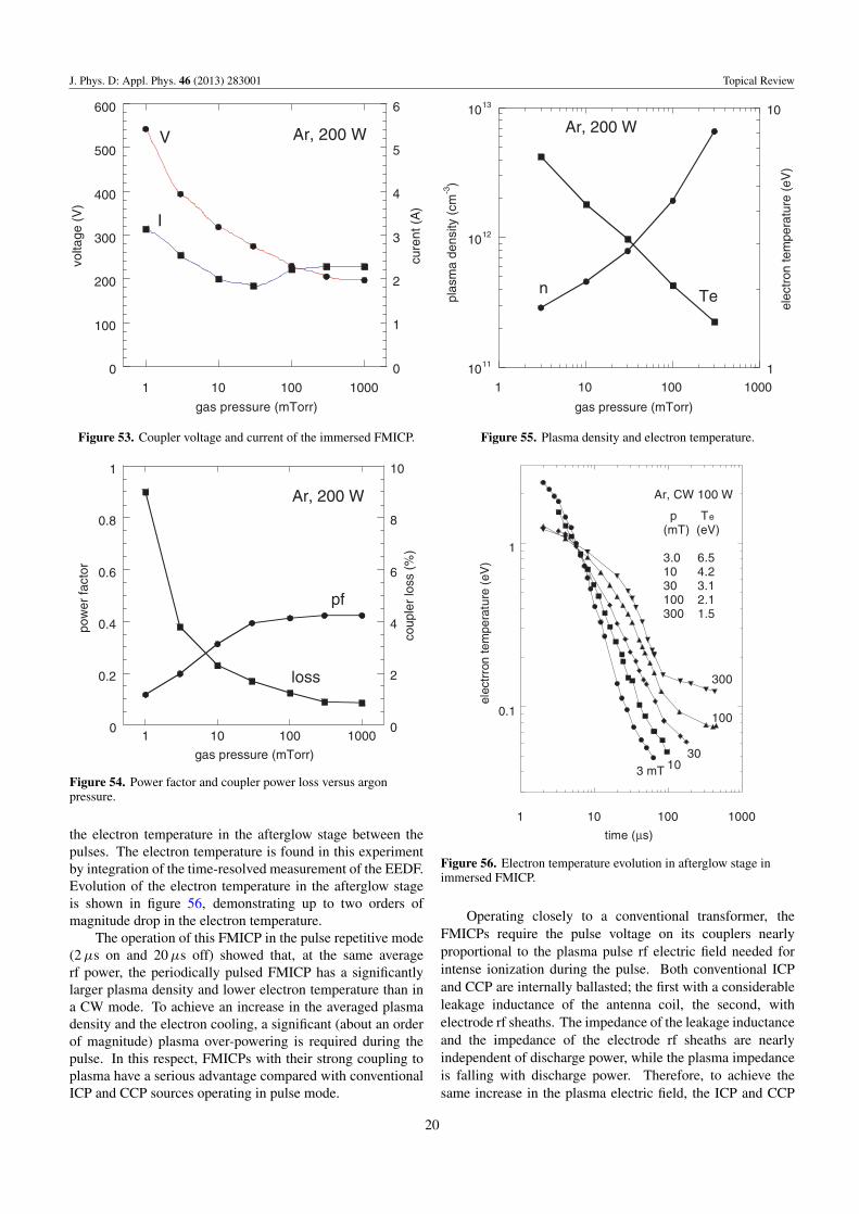
In this pressure range and the input power of 200 W, theinput resistance of the coupler loaded with plasma changedbetween 20 and 60 �, being equal to 50 � at 10 mTorr, thusensuring the exact matching to the power source. The electricaland plasma characteristics measured in this FMICP at a totalpower 200 W, as a function of argon pressure are shown infigures 53– 55.
A high power factor (around 0.4) and a very small relativepower loss (less than 2%), at argon pressure 15 mTorr andhigher, is seen in figure 54. These numbers are close tocorresponding numbers found in the FMICP with closedmagnetic path. In general, the effective permeability µeff
of the rod (or tubular) couplers (depending on the corelength) is around 10, being somewhere between µeff ofopened cores (µeff = 1.5–2) and those of closed cores(µeff = 50–2000). Correspondingly, the coupling, powerfactor and relative coupler loss in the immersed core FMICPshas some intermediate, but closer to the values of FMICPs withclosed couplers. More details on this kind of FMICP will bepublished elsewhere.
An operation of this FMIPC in the pulse mode is reportedin [63]. The pulse mode allows for considerable reduction in
19
J. Phys. D: Appl. Phys. 46 (2013) 283001 Topical Review
0
100
200
300
400
500
600
0
1
2
3
4
5
6
1 10 100 1000
volta
ge (
V)
cure
nt (
A)
gas pressure (mTorr)
V
I
Ar, 200 W
Figure 53. Coupler voltage and current of the immersed FMICP.
0
0.2
0.4
0.6
0.8
1
0
2
4
6
8
10
1 10 100 1000
pow
er fa
ctor
coup
ler
loss
(%
)
gas pressure (mTorr)
pf
loss
Ar, 200 W
Figure 54. Power factor and coupler power loss versus argonpressure.
the electron temperature in the afterglow stage between thepulses. The electron temperature is found in this experimentby integration of the time-resolved measurement of the EEDF.Evolution of the electron temperature in the afterglow stageis shown in figure 56, demonstrating up to two orders ofmagnitude drop in the electron temperature.
The operation of this FMICP in the pulse repetitive mode(2 µs on and 20 µs off) showed that, at the same averagerf power, the periodically pulsed FMICP has a significantlylarger plasma density and lower electron temperature than ina CW mode. To achieve an increase in the averaged plasmadensity and the electron cooling, a significant (about an orderof magnitude) plasma over-powering is required during thepulse. In this respect, FMICPs with their strong coupling toplasma have a serious advantage compared with conventionalICP and CCP sources operating in pulse mode.
1011
1012
1013
1
10
1 10 100 1000
plas
ma
dens
ity (
cm-3
)
elec
tron
tem
pera
ture
(eV
)
gas pressure (mTorr)
Ten
Ar, 200 W
Figure 55. Plasma density and electron temperature.
0.1
1
1 10 100 1000
elec
trro
n te
mpe
ratu
re (
eV)
time (µs)
300
100
303 mT 10
Ar, CW 100 W
p Te
(mT) (eV)
3.0 6.510 4.230 3.1 100 2.1300 1.5
Figure 56. Electron temperature evolution in afterglow stage inimmersed FMICP.
Operating closely to a conventional transformer, theFMICPs require the pulse voltage on its couplers nearlyproportional to the plasma pulse rf electric field needed forintense ionization during the pulse. Both conventional ICPand CCP are internally ballasted; the first with a considerableleakage inductance of the antenna coil, the second, withelectrode rf sheaths. The impedance of the leakage inductanceand the impedance of the electrode rf sheaths are nearlyindependent of discharge power, while the plasma impedanceis falling with discharge power. Therefore, to achieve thesame increase in the plasma electric field, the ICP and CCP
20

J. Phys. D: Appl. Phys. 46 (2013) 283001 Topical Review
Figure 57. Compact rf cathode.
0.8
0.85
0.9
0.95
1
0 50 100 150 200 250
p = 0.5 mT, Vex
= 30 V pow
er t
rans
fer
effic
ienc
y
RF power (W)
Figure 58. Power transfer efficiency of the rf cathode.
require significantly larger overvoltage than FMICP. Havingrather high rf voltages even in the CW mode, the operating ofthese discharges in the pulse mode would require excessivelyhigh rf voltages that may cause significant problems.
Another advantage of using of FMICPs in the pulse modeis a relatively low Q-factor of their coupler-matching networks,Q = (Cosφ−2 − 1)1/2. Considerably larger Q-factors ofconventional ICP and especially that of CCP is the reasonfor their inability of fast interrupting the discharges due tothe ringing of their coupler-matching networks having largeQ-factors. The ringing time of a few microseconds in apulse-driven CCP at 13.56 MHz has been reported in [64].
A compact plasma cathode for a thruster ion beamneutralization built as an FMICP with immersed coupler isreported in [65]. The plasma cathode consisting of dischargechamber with 7.6 cm OD and 11.5 cm length has an immersedrf ferrite coupler cooled with a cape sink that houses amatching-tuning network and a variety of ports for startingand diagnostics means, is shown in figure 57. The cathodeis operated at 2.0 MHz with xenon gases in the power rangebetween 20 and 200 W. The electron beam is extracted fromthe NW16 pumping port (on the right-hand side in figure 57)to 30 V biased collector.
The power transfer efficiency of this plasma cathodeversus the total power delivered to the matching network isshown in figure 58. The efficiency is 97% at 0.5 mTorr xenon
0
1
2
3
4
5
0 50 100 150 200 250
p = 0.5 mT, Vex
= 30 V
extr
acte
d cu
rren
t (A
)
RF power (W)
Figure 59. Extracted electron current versus total rf power.
gas downstream pressure, when the power exceeds 70 W. Theextracted electron current as a function of the total power isshown in figure 59. The extracted current is nearly proportionalto the rf power with the emission efficiency of 20 mA W−1,corresponding to the electron production cost of 50 eV. Theelectron emission efficiency of 25 mA W−1 was maximal at2 mTorr of downstream pressure, that considerably exceedsthe emission efficiency of 14 mA W−1 at 60 V extractionvoltage obtained in a microwave plasma cathode [66, 67]and of 12.5 mA W−1 at 80 V extraction voltage obtained ina helicon plasma cathode operating at 13.65 MHz [68, 69].Apart from higher efficiency the described immersed FMICP isconsiderably simpler and cheaper than microwave and heliconplasma cathodes. It is apparent that with an appropriateextraction-accelerating system this kind of FMICP can operateas a highly efficient ion source.
7. Concluding remarks
In this review, we have considered a variety of FMICPapplications and presented a detailed comparative study oftheir electrical and plasma parameters. We have demonstratedmany advantages of these plasma sources compared withconventional ICPs. The introduction of a ferromagnetic coreto a magnetic rf circuit of an ICP enhances the coupling andcauses the FMICP to operate close to an ideal transformer,thus increasing its efficiency and power factor. This simplifiesconsiderably the FMICP matching to an rf source. Applying aferromagnetic core also allows for a considerable reduction inthe FMICP driving frequency (up to 2–3 orders of magnitude)compared with the standard of 13.56 MHz in the industry. Byreducing the operation frequency and using the push-pull drive,one eliminates the capacitive coupling and transmission lineeffects, inherent to ICP operating at 13.56 MHz. Utilizationof lower frequencies also results in more efficient and lessexpensive rf power sources. Due to strong coupling, theapplication of FMICP operating in the pulse mode is easierand more reliable than the application of conventional ICP
21

J. Phys. D: Appl. Phys. 46 (2013) 283001 Topical Review
and CCP sources. One of the features of FMICP, valuable forplasma processing, is its ability to focus rf power injection,which allows for effective control of plasma profiles, which isnecessary for uniform plasma processing over large substrateareas.
The experiments presented in this review show that aproperly designed FMICP can operate over a wide range of rfpower and gas pressure, and it can do everything that other rfand microwave plasma sources can do, but more efficientlyand more cost effectively.
Acknowledgment
This work was partly supported by the DOE OFEC (Contract# DE-SC00019390).
References
[1] Hershkowitz N, Ding J, Breun R A, Chen R T S, Mayer J andQuick A K 1996 Phys. Plasmas 3 2197
[2] Godyak V A 2006 IEEE Trans. Plasma Sci. 34 755[3] Lieberman M A and Lichtenberg A J 2005 Principles of
Plasma Discharges and Material Processing (New York:Wiley)
[4] Chen F F and Chang J P 2002 Lecture Notes on Principles ofPlasma Processing (Dordrecht/New York: Kluwer/Plenum)
[5] Lieberman M A, Booth J P, Chabert P, Rax J M andTurner M M 2002 Plasma Sources Sci. Technol. 11 283
[6] Chabert P 2007 J. Phys. D: Appl. Phys. 40 R63[7] Chabert P, Raimbault J L, Levif P, Rax J M and
Lieberman M A 2005 Phys. Rev. Lett. 95 205001[8] Volynets V, Ushakov A, Lim G, Lim Y, Shin H, Woo J,
Kim K and Sung D 2008 J. Vac. Sci. Technol. A 26 406[9] Meziani T, Colpo P and Rossi F 2001 Plasma Sources Sci.
Technol. 10 276[10] Godyak V A 2003 Presentation at PEUG (Santa Clara, CA,
September 2003)[11] Godyak V A 2004 Proc. 15th Int. Conf. on Gas Discharges
and their Applications (Toulouse, France) vol 2 p 621[12] Colpo P, Meziani T and Rossi F 2005 J. Vac. Sci. Technol. A
23 270[13] Chen F F, Evans J D and Tynan G R 2001 Plasma Sources Sci.
Technol. 10 236[14] Godyak V A and Chung C-W 2006 Japan J. Appl. Phys.
45 8035[15] Lim J H, Kim K N, Park J K and Yeom G Y 2008 J. Korean
Phys. Soc. 52 313[16] Godyak V A 2002 IEEE Industry Appl. Mag. 42[17] Boulos M I 1985 Pure Appl. Chem. 57 1321[18] Eckert H U 1984 2nd Annual Int. Conf. om Plasma Chemistry
Technology (San Diego, CA) p 171[19] Hopwood J 1992 Plasma Source Sci. Technol. 1 109[20] Keller J H 1997 Plasma Phys. Control. Fusion 39 A437[21] Godyak V A 2003 Plasma Phys. Control. Fusion 45 A399[22] Godyak V A 2005 Phys. Plasmas 12 3553[23] Kral’kina E A 2008 Usp. Fiz. Nauk 178 519[24] Chabert P and Braithwaite N 2011 Physics of Radio-Frequency
Plasmas (Cambridge: Cambridge University Press)[25] Bethenod J and Claude A 1936 US Patent 2,030,957[26] Netten A and Verheij C M 1991 Operating Principles of the
Philips QL Lamp System (Eindhoven: PhilipsLighting V. G.)
[27] Green B J 2003 Plasma Phys. Control. Fusion 45 687[28] Bell W E 1965 Appl. Phys. Lett. 7 190[29] Anderson J M 1969 Trans. (April) IES 236
[30] Godyak V A and Schaffer J 1998 Proc. 8th Int. Symp. onSci. and Technol. of Light Sources (Greifswald, Germany)p 14
[31] Statnic E 2004 Proc. 10th Int. Symp. on Sci. and Technol. ofLight Sources (Toulouse, France) p 287
[32] Kogan V A and Ulanov I M 1993 High Temp. 31 129[33] Smith D K, Chen X, Holber W M and Georgelis E 1998 US
Patent 6,150,628[34] Lloyd S, Shaw D M, Watanabe M and Collins G J 1999 Japan.
J. Appl. Phys. 38 4275[35] Shaffer J and Godyak V A 1999 J. Illum. Eng. Soc. 28 142[36] Godyak V A, Piejak R B and Alexandrovich B M Proc. 9th
Int. Symp. on the Science and Technology of Light Sources(Cornel University, Ithaca, NY) p 157
[37] Alexandrovich B M, Godyak V A and Lister G G 2004 Proc.10th Int. Symp. on the Science and Technology of LightSources (Toulouse, France) p 283
[38] Lister G G, Lawler J E, Lapatovich W P and Godyak V A2004 Rev. Mod. Phys. 76 541
[39] Wharmby D O 1997 Lamp and Lighting (New York: Wiley)p 216
[40] Godyak V A, Alexandrovich B M, Sapozhnikov A A andSpeer R 2007 Proc. 11th Int. Symp. on the Scienceand Technology of Light Sources (Shanghai, China)p 377
[41] Reinbeg A R, Steinberg G N and Zarowin C B 1984US Patent 4,431,898
[42] Hiramatsu K and Takamura S 1992 Japan. J. Appl. Phys.31 2243
[43] Watanabe Y and Ohta K 2002 Proc. ESCAMPIG16(Grenoble) p 245
[44] Zhang B C and Cross R C 1998 Rev. Sci. Instrum.69 101
[45] Zhang B C and Cross R C 1998 J. Vac. Sci. Technol. A16 2016
[46] Ulanov I M and Isupov M V 2010 Applied Physics in the 21stCentury (New York: Nova Science Publishers) p 113chapter 3
[47] Bliokh Yu P, Feisteiner J, Slutsker Ya Z and Vaisberg P M2004 Appl. Phys. Lett. 85 1484
[48] Eckert H U 1974 IEEE Trans. Plasma Sci. 2 308[49] Piejak R B, Godyak V A and Alexandrovich B M 1992
Plasma Sources Sci. Technol. 1 179[50] Godyak V A, Piejak R B, Alexandrovich B M and
Kolobov V I 1998 Phys. Rev. Lett. 80 3264[51] Lieberman M A and Godyak V 1998 IEEE Trans. Plasma Sci.
26 955[52] Godyak V A 1998 Electron Kinetics and Application of Glow
Discharges (New York: Plenum Press) p 241[53] Shinohara S, Miyauchi Y and Kawai Y 1995 Plasma Phys.
Control. Fusion 37 1015[54] Lim J H, Kim K N, Gweon G H and Yeom G Y 2009 J. Phys.
D: Appl. Phys. 42 015204[55] Lim J H, Kim K N, Gweon G H, Hong S P, Kim S H and
Yeom G Y 2010 J. Phys. D: Appl. Phys. 43 095202[56] Lee K, Lee Y, Jo S, Chung C-W and Godyak V A 2008
Plasma Sources Sci. Technol. 17 015014[57] Bang J-Y, Kim J-Y and Chung C-W 2011 Phys. Plasma
18 073507[58] Ulanov I M, Isupov M V, Aleshina L A, Glazkova S V and
Loginov D V 2012 7th Int. Conf. on Plasma Technology(Minsk, Belarus) vol 1 p 208
[59] Godyak V A 2011 Plasma Sources Sci. Technol. 20 025004[60] Godyak V A, Piejak R B and Alexandrovich B M 1999
J. Appl. Phys. 85 703[61] www.plasmasensors.com[62] Nagorny V P and Lee D 2011 ISPC 20 (Philadelphia, PA)[63] Godyak V A and Alexandrovich B M 2005 27th ICPIG
(Eindhoven, The Nederlands) vol 1 p 221
22

J. Phys. D: Appl. Phys. 46 (2013) 283001 Topical Review
[64] Pu Y-K 2012 private communication[65] Godyak V A, Raitses Y and Fisch N J 2007 Proc.
30th Int. Electric Propulsion Conf. (Florence,Italy) p 266
[66] Diamant K K 2005 41st Joint Propulsion Conf. andExhibit (Tucson, AZ) AIAA 3662
[67] Diamant K K 2005 29th Int. Electric Propulsion Conf.(Princeton, NJ) IEPC 007
[68] Longmier B and Hershkowitz N 2005 41st Joint PropulsionConf. and Exhibit. (Tucson, AZ) AIAA 3856
[69] Longmier B, Baalrud S and Hershkowitz N 2006 Rev. Sci.Instrum. 77 113504
23