topic standard nomenclature of seismic...
TRANSCRIPT
Information Sheet IS 2.1
1
Topic Standard nomenclature of seismic phases Authors Dmitry A. Storchak, International Seismological Centre, Pipers Lane,
Thatcham, Berkshire RG19 4NS, UK, England, E-mail: [email protected]
Peter Bormann (formerly GeoForschungsZentrum Potsdam, Telegrafenberg, D-14473 Potsdam, Germany); E-mail: [email protected]
Johannes Schweitzer, NORSAR, P.O. Box 53, N-2027, Kjeller, Norway, E-mail: johannes @norsar.no
Version October 2002
1 Introduction At its meeting in Hanoi, August 23, 2001, the IASPEI Commission on Seismological Observation and Interpretation decided to set up a Working Group on Standard Phase Names, chaired by D. A. Storchak of the ISC. Members of the group were R. D. Adams, P. Bormann, R. E. Engdahl, J. Havskov, B. L. N. Kennett and J. Schweitzer. The working group has put together a modified standard nomenclature of seismic phases, which was meant to be concise, consistent and self-explanatory on the basis of agreed rules. We did not try to create a complete list of all phases. The list is open for further development. The list is not meant to satisfy specific requirements of seismologists to name various phases used in a particular type of research. Instead, the new phase list aims at inviting data analysts and other users to ensure an expanded standardized data reporting and exchange. This will result in a broader and unambiguous database for research and practical applications. At the same time the attached list and its principles outlined below may be a useful guidance when proposing names to previously unknown seismic phases. The new nomenclature partially modifies and complements the earlier one published in the last edition of the Manual of Seismological Observatory Practice (Willmore, 1979) and every year in the January issue of the seismic bulletins published by the ISC. It is more in tune with phase definitions according to modern Earth and travel-time models (see 2.7) and the definition of pronounced travel-time branches, of core phases in particular (see manual sections 11.5.2.4 and 11.5.3). As opposed to former practice, the WG tried to make sure that the phase name generally reflects the type of the wave and the path it has traveled. Accordingly, symbols for characterizing onset quality, polarity etc. will no longer be part of the phase name. Also, the WG acknowledges that there exist several kinds of seismic phases, crustal phases in particular, which are common in some regions but are not or only rarely found in other regions, such as e.g., Pb (P*), PnPn, PbPb, etc.. The names and definitions of acoustic and amplitude measurement phases are likely to be reviewed based on the results of recent developments in the data centers and new analysis practices being established. The extended list of phase names as presented below in section 4 accounts for significantly increased detection capabilities of modern seismic sensors and sensor arrays, even of rather weak phases, which were rarely found on the classical analog records. It also accounts for improved possibilities of proper phase identification by means of digital multi-channel data processing such as frequency-wavenumber (f-k) analysis and polarization filtering, by modeling the observations with synthetic seismograms or by showing on the records the
Information Sheet IS 2.1
2
theoretically predicted onset times of phases. Furthermore, limitation of classical formats for wave parameter reporting to international data centers, such as the Telegraphic Format (TF), which allowed only the use of capital letters and numbers, are no longer relevant in times of data exchange via the Internet. Finally, the newly adopted IASPEI Seismic Format (ISF; see 10.2.5 and IS 10.2) is much more flexible then the old formats accepted by the NEIC, ISC and other data centers. It also allows the reporting, computer parsing and archiving of phases with longer or up to now uncommon names. ISF also accepts complementary parameters such as onset quality, measured backazimuth and slowness, amplitudes and periods of other phases in addition to P and surface waves, for components other than vertical ones, and for non-standard response characteristics. This increased flexibility of the parameter-reporting format requires improved standardization, which limits an uncontrolled growth of incompatible and ambiguous parameter data. Therefore, the WG agreed on certain rules. They are outlined below prior to the listing of standardized phase names. In order to ease the understanding of verbal definitions of the phase names, ray diagrams are presented in the last section. They have been calculated for local seismic sources on the basis of an average one-dimensional two-layer crustal model and for regional and teleseismic sources by using the global 1D-Earth model AK135 (Kennett et al., 1995; see also Fig. 2.53). Further examples of ray paths of typical seismic phases are presented in Fig. 2.42 and in various figures of Chapter 11. For polarization and amplitude features, phase and group velocities etc. of the various phases see Chapter 2. Before elaborating short-cut seismic phase names one should agree first on the language to be used and its rules. As in any other language we need a suitable alphabet (here Latin letters), numbers (here Arabic numbers and + and - signs), an orthography, which regulates, e.g., the use of capital and lower case letters, and a syntax, i.e., rules of correct order and mutual relationship of the language elements. One should be aware, however, that the seismological nomenclature will inevitably develop exceptions to the rules, as any historically developed language, and depending on the context in which it is used. Although not fully documented below, some exceptions will be mentioned. Note that our efforts are mainly aimed at standardized names to be used in international data exchange so as to build up unique, unambiguous global databases for research. Many of the exceptions to the rules are related to specialized, mostly local research applications. The identification of related seismic phases often requires specialized procedures of data acquisition and processing, which are not part of seismological routine data analysis. Also, many of these exceptional phases are rarely or never used in seismic event location, magnitude determination, source mechanism calculations etc., which are the main tasks of international data centers. Below, we focus therefore on phases, which are particularly important for seismological data centers as well as for the refinement of regional and global Earth models on the basis of widely exchanged and accumulated parameter readings from such phases. In addition, we added for some phase definitions references to which the particular phase names can be traced back. For better illustration of the verbal definition of phase names, ray diagrams for the most important phases are presented in section 5.

Information Sheet IS 2.1
3
2 Standard letters, signs and syntax used for describing seismic phases Capital letters: Individual capital letters that stand for primary types of seismic body waves such as:
• P: longitudinal wave which has traveled through Earth crust and mantle, from undae primae (Latin) = first waves (Borne, 1904);
• K: longitudinal wave which has traveled through the Earth’s outer core, for Kern (German) = core (Sohon, 1932; Bastings, 1934);
• I: longitudinal wave which has traveled through the Earth’s inner core (Jeffreys and Bullen, 1940);
• S: transverse wave which has traveled through Earth crust and mantle, from undae secundae (Latin) = second waves (Borne, 1904);
• T: a wave, which has partly traveled as sound wave in the sea, from undae tertiae = third waves (Linehan, 1940);
• J: transverse wave which has traveled through the Earth’s inner core (Bullen, 1946).
Exceptions:
• A capital letter N used in the nomenclature does not stand for a phase name but rather for the number of legs traveled (or N-1 reflections made) before reaching the station. N should usually follow the phase symbol to which it applies. For examples see syntax below.
• The lower case letters p and s may stand, in the case of seismic events below the Earth’s surface, for the relatively short upgoing leg of P or S waves, which continue, after reflection and possible conversion at the free surface, as downgoing P or S wave. Thus seismic depth phases (e.g., pP, sP, sS, pPP, sPP, pPKP, etc.) are uniquely defined. The identification and reporting of such phases is of utmost importance for a better event location, and improved source depth in particular (Scrase, 1931; Stechschulte, 1932).
• Another exception is, that many researchers working on detailed investigations of crustal and upper mantle discontinuities, e.g., by using the receiver function method, write both the up- and down-going short legs of converted or multiply reflected P and S phases as lower case letters p and s, respectively.
Individual or double capital letters that stand for surface waves such as:
• L: (relatively) long-period surface wave, unspecified, from undae longae (Latin) = long waves (Borne, 1904);
• R: Rayleigh waves (short-period up to very long-period, mantle waves) (Angenheister, 1921);
• Q: Love waves, from Querwellen (German) = transverse waves (Angenheister, 1921);
• G: (very long-period) global (mantle) Love waves, firstly observed and reported by Gutenberg and Richter (1934); Byerly proposed the usage of G for Gutenberg, as reported by Richter (1958);

Information Sheet IS 2.1
4
• LR: long-period Rayleigh waves, usually relating to the Airy-phase maximum in the surface wave train;
• LQ: long-period Love waves. Lower case letters and signs Single lower case letters generally specify in which part of Earth crust or upper mantle a phase has its turning point or at which discontinuity it has been reflected and eventually converted:
• g: after the phase name characterizes waves “bottoming” (i.e., having their turning point in case of P-or S-body waves) or just travel (surface waves) within the upper (“granitic”) Earth crust (e.g., Pg, Sg; Rg), (Jeffreys, 1926);
• b: after the phase name characterizes body waves “bottoming” (i.e., having their turning point) in the lower (“basaltic”) Earth crust (Jeffreys, 1926) (e.g., Pb, Sb; alternative names for these phases are P*, S*, (Conrad, 1925));
• n: after the phase name characterizes a P or S wave which is bottoming (i.e., has its turning point) or is traveling as head wave in the Earth’s uppermost mantle (e.g., Pn, Sn), introduced after Andrija Mohorovičić discovered the Earth crust and separated the crustal travel-time curve from the (n =) normal mantle phase (Mohorovičić, 1910);
• m: stands for (upward) reflections from the outer side of the Mohorovičić (Moho) discontinuity (e.g., PmP, SmS);
• c: stands for reflections from the outer side of the core-mantle boundary (CMB), usage proposed by James B. Macelwane (see Gutenberg, 1925);
• i: stands for reflections from the outer side of the inner core boundary (ICB); • z: stands for reflections from a discontinuity at depth z (measured in km) (any other
than free surface, CMB or ICB!). Upward reflections from the outer side of the discontinuity may additionally be complemented by a + sign (e.g., P410+P; this, however, is not compulsory!) while downward reflections from the inner side of the discontinuity must be complemented by a – sign (e.g., P660-P).
Double lower case letters following a capital letter phase name indicate the travel-time branch to which this phase belongs. Due to the geometry and velocity structure of the Earth the same type of seismic wave may develop a triplication of its travel-time curve with different, in some parts well separated branches (see Fig. 2.29). Thus it is customary to differentiate between different branches of core phases and their multiple reflections at the free surface or the CMB. Examples are PKPab, PKPbc, PKPdf, SKSac, SKKSac, etc. (for definitions see the list below). The separation of the different PKP branches with letters ab, bc and df was introduced by Jeffreys and Bullen (1940). Three lower case letters may follow a capital letter phase name in order to specify its character, e.g., as a forerunner (pre) to the main phase, caused by scattering (e.g., PKPpre) or as a diffracted wave extending the travel-time branch of the main phase into the outer core shadow (e.g., Pdif in the outer core shadow for P).

Information Sheet IS 2.1
5
Syntax of generating complex phase names Due to refraction, reflection and conversion in the Earth the majority of phases have a complex path history before they reach the station. Accordingly, most phases cannot be described by a single capital letter code in a self-explanatory way. By combining, however, the capital and lower case letters as mentioned above one can describe the character of even rather complex refracted, reflected or converted phases. The order of symbols (syntax) regulates the sequence of phase legs due to refraction, reflection and conversion events in time (from left to right) and in space. 3 Examples for creating complex standard phase names Refracted and converted refracted waves:
• PKP is a pure refracted longitudinal wave. It has traveled the first part of its path as P through crust and mantle, the second through the outer core and the third again as P through mantle and crust. The alternative name for PKP is P’ (Angenheister, 1921).
• PKIKP (alternative to PKPdf) is a pure refracted longitudinal wave too. It has traveled the first part of its path as P through crust and mantle, the second through the outer core, the third through the inner core, and the fourth and fifth parts back again through outer core and mantle/crust.
• SKS is a converted refracted wave. It has traveled as a shear wave through crust and mantle, being converted into a longitudinal wave K when refracted into the outer core and being converted back again into an S wave when entering the mantle.
• SKP or PKS are converted refracted waves in an analogous way with only one conversion from S to K when entering the core or from K to S when leaving the core, respectively.
Pure reflected waves:
• In the case of (downward only) reflections at the free surface or from the inner side of the CMB the phase symbol is just repeated, e.g., PP, PPP, KK, KKK etc.
• In the case of (upward) reflections from the outer side of the Moho, the CMB or the ICB this is indicated by inserting between the phase symbols m, c or i, respectively: e.g., PmP, PcP, ScS; PKiKP;
• In the case of reflections from any other discontinuity in mantle or crust at depth z these may be from the inner side (-; i.e., downward back into the mantle) or from the outer side (+; i.e., back towards the surface). In order to differentiate between these two possibilities, the sign has to follow z (or the respective number in km), e.g., P410+P or P660-P;
• To abbreviate names of multi-leg phases due to repeated reflections one can also write PhasenameN. This kind of abbreviation, is rather customary in case of multiple phases with long phase names such as PmP2 for PmPPmP (surface reflection of PmP), SKS2 for SKSSKS (which is the alternative name for S'2, the free surface reflection of SKS), PKP3 for PKPPKPPKP (double surface reflection of PKP; alternative name to P'3) or P4KP for PKKKKP (triple reflection of K at the inner side of the CMB).
Information Sheet IS 2.1
6
Note 1: PKP2 = PKPPKP are now alternative names for P'2 or P'P', respectively. This should not be mistaken for the old name PKP2 for PKPab! Note 2: In the case of multiple reflections from the inner side of the CMB the WG followed the established tradition to place the number N not after but in front of the related phase symbol K. Reflected waves with conversion at the reflection point: In the case that a phase changes its character from P to S, or vice versa, one writes:
• PS (first leg P, second leg S) or SP (first leg P, second leg S) in the case of reflection from the free surface downward into the mantle;
• PmS or SmP, respectively, for reflections/conversions from the outer side of the Moho;
• PcS or ScP for reflections/conversions from the outer side of the CMB; • Pz+S or Sz-P for reflection/conversion from the outer side or inner side,
respectively, of a discontinuity at depth z. Note that the - is compulsory, the + not!
In this context it is worth mentioning, that mode conversion is impossible for reflections from K from the inner side of the CMB back into the outer core because the liquid outer core does not allow the propagation of S waves. Along these lines and rules the new IASPEI standard phase names have been agreed. Where these deviate from other traditionally used names the latter are given as well. Either, they are still acceptable alternative names (alt) where the latter have been created in consistence with the above mentioned rules (e.g., PKIKP instead of PKPdf) or they are now old names (old), which should no longer be used.
Information Sheet IS 2.1
7
4 IASPEI Standard Seismic Phase List (Draft) This draft was agreed in May 2002 by the IASPEI Working Group on Phase Names, chaired by D. A. Storchak. Other members of the WG were R. D. Adams, P. Bormann, R. E. Engdahl, J. Havskov, B. Kennett and J. Schweitzer. The draft requires adoption by the IASPEI Commission on Seismological Observation and Interpretation (CoSOI) at its forthcoming meeting in Sapporo, 2003. --------------------------- CRUSTAL PHASES --------------------------- Pg At short distances, either an upgoing P wave from a source in the upper crust
or a P wave bottoming in the upper crust. At larger distances also arrivals caused by multiple P-wave reverberations inside the whole crust with a group velocity around 5.8 km/s.
Pb (alt:P*) Either an upgoing P wave from a source in the lower crust or a P wave bottoming in the lower crust
Pn Any P wave bottoming in the uppermost mantle or an upgoing P wave from a source in the uppermost mantle
PnPn Pn free surface reflection PgPg Pg free surface reflection PmP P reflection from the outer side of the Moho PmPN PmP multiple free surface reflection; N is a positive integer. For example,
PmP2 is PmPPmP PmS P to S reflection from the outer side of the Moho Sg At short distances, either an upgoing S wave from a source in the upper crust
or an S wave bottoming in the upper crust. At larger distances also arrivals caused by superposition of multiple S-wave reverberations and SV to P and/or P to SV conversions inside the whole crust.
Sb (alt:S*) Either an upgoing S wave from a source in the lower crust or an S wave bottoming in the lower crust
Sn Any S wave bottoming in the uppermost mantle or an upgoing S wave from a source in the uppermost mantle
SnSn Sn free surface reflection SgSg Sg free surface reflection SmS S reflection from the outer side of the Moho SmSN SmS multiple free surface reflection; N is a positive integer. For example,
SmS2 is SmSSmS SmP S to P reflection from the outer side of the Moho Lg A wave group observed at larger regional distances and caused by
superposition of multiple S-wave reverberations and SV to P and/or P to SV conversions inside the whole crust. The maximum energy travels with a group velocity around 3.5 km/s
Rg Short period crustal Rayleigh wave
Information Sheet IS 2.1
8
------------------------- MANTLE PHASES ------------------------- P A longitudinal wave, bottoming below the uppermost mantle; also an upgoing
longitudinal wave from a source below the uppermost mantle PP Free surface reflection of P wave leaving a source downwards PS P, leaving a source downwards, reflected as an S at the free surface. At shorter
distances the first leg is represented by a crustal P wave. PPP analogous to PP PPS PP to S converted reflection at the free surface; travel time matches that of PSP PSS PS reflected at the free surface PcP P reflection from the core-mantle boundary (CMB) PcS P to S converted reflection from the CMB PcPN PcP multiple free surface reflection; N is a positive integer. For example PcP2
is PcPPcP Pz+P (alt:PzP) P reflection from outer side of a discontinuity at depth z; z may be a
positive numerical value in km. For example P660+P is a P reflection from the top of the 660 km discontinuity.
Pz-P P reflection from inner side of discontinuity at depth z. For example, P660-P is a P reflection from below the 660 km discontinuity, which means it is precursory to PP.
Pz+S (alt:PzS) P to S converted reflection from outer side of discontinuity at depth z. Pz-S P to S converted reflection from inner side of discontinuity at depth z PScS P (leaving a source downwards) to ScS reflection at the free surface Pdif (old:Pdiff) P diffracted along the CMB in the mantle S shear wave, bottoming below the uppermost mantle; also an upgoing shear
wave from a source below the uppermost mantle SS free surface reflection of an S wave leaving a source downwards SP S, leaving source downwards, reflected as P at the free surface. At shorter
distances the second leg is represented by a crustal P wave. SSS analogous to SS SSP SS to P converted reflection at the free surface; travel time matches that of SPS. SPP SP reflected at the free surface ScS S reflection from the CMB ScP S to P converted reflection from the CMB ScSN ScS multiple free surface reflection; N is a positive integer. For example ScS2
is ScSScS Sz+S (alt:SzS) S reflection from outer side of a discontinuity at depth z; z may be a
positive numerical value in km. For example S660+S is an S reflection from the top of the 660 km discontinuity.
Sz-S S reflection from inner side of discontinuity at depth z. For example, S660-S is an S reflection from below the 660 km discontinuity, which means it is precursory to SS.
Sz+P (alt:SzP) S to P converted reflection from outer side of discontinuity at depth z Sz-P S to P converted reflection from inner side of discontinuity at depth z ScSP ScS to P reflection at the free surface Sdif (old:Sdiff) S diffracted along the CMB in the mantle

Information Sheet IS 2.1
9
--------------------- CORE PHASES --------------------- PKP (alt:P') unspecified P wave bottoming in the core PKPab (old:PKP2) P wave bottoming in the upper outer core; ab indicates the
retrograde branch of the PKP caustic PKPbc (old:PKP1) P wave bottoming in the lower outer core; bc indicates the
prograde branch of the PKP caustic PKPdf (alt:PKIKP) P wave bottoming in the inner core PKPpre (old:PKhKP) a precursor to PKPdf due to scattering near or at the CMB PKPdif P wave diffracted at the inner core boundary (ICB) in the outer core PKS Unspecified P wave bottoming in the core and converting to S at the CMB PKSab PKS bottoming in the upper outer core PKSbc PKS bottoming in the lower outer core PKSdf PKS bottoming in the inner core P'P' (alt:PKPPKP) Free surface reflection of PKP P'N (alt:PKPN) PKP reflected at the free surface N-1 times; N is a positive integer.
For example P'3 is P'P'P' P'z-P' PKP reflected from inner side of a discontinuity at depth z outside the core,
which means it is precursory to P'P'; z may be a positive numerical value in km P'S' (alt:PKPSKS) PKP to SKS converted reflection at the free surface; other
examples are P'PKS, P'SKP PS' (alt:PSKS) P (leaving a source downwards) to SKS reflection at the free
surface PKKP Unspecified P wave reflected once from the inner side of the CMB PKKPab PKKP bottoming in the upper outer core PKKPbc PKKP bottoming in the lower outer core PKKPdf PKKP bottoming in the inner core PNKP P wave reflected N-1 times from inner side of the CMB; N is a positive integer PKKPpre a precursor to PKKP due to scattering near the CMB PKiKP P wave reflected from the inner core boundary (ICB) PKNIKP P wave reflected N-1 times from the inner side of the ICB PKJKP P wave traversing the outer core as P and the inner core as S PKKS P wave reflected once from inner side of the CMB and converted to S at the
CMB PKKSab PKKS bottoming in the upper outer core PKKSbc PKKS bottoming in the lower outer core PKKSdf PKKS bottoming in the inner core PcPP' (alt:PcPPKP) PcP to PKP reflection at the free surface; other examples are
PcPS', PcSP', PcSS', PcPSKP, PcSSKP SKS (alt:S') unspecified S wave traversing the core as P SKSac SKS bottoming in the outer core SKSdf (alt:SKIKS) SKS bottoming in the inner core

Information Sheet IS 2.1
10
SPdifKS (alt:SKPdifS) SKS wave with a segment of mantle-side Pdif at the source and/or the receiver side of the raypath
SKP Unspecified S wave traversing the core and then the mantle as P SKPab SKP bottoming in the upper outer core SKPbc SKP bottoming in the lower outer core SKPdf SKP bottoming in the inner core S'S' (alt:SKSSKS) Free surface reflection of SKS S'N SKS reflected at the free surface N-1 times; N is a positive integer S'z-S' SKS reflected from inner side of discontinuity at depth z outside the core,
which means it is precursory to S'S'; z may be a positive numerical value in km S'P' (alt:SKSPKP) SKS to PKP converted reflection at the free surface; other
examples are S'SKP, S'PKS S'P (alt:SKSP) SKS to P reflection at the free surface SKKS Unspecified S wave reflected once from inner side of the CMB SKKSac SKKS bottoming in the outer core SKKSdf SKKS bottoming in the inner core SNKS S wave reflected N-1 times from inner side of the CMB; N is a positive integer SKiKS S wave traversing the outer core as P and reflected from the ICB SKJKS S wave traversing the outer core as P and the inner core as S SKKP S wave traversing the core as P with one reflection from the inner side of the
CMB and then continuing as P in the mantle SKKPab SKKP bottoming in the upper outer core SKKPbc SKKP bottoming in the lower outer core SKKPdf SKKP bottoming in the inner core ScSS' (alt:ScSSKS) ScS to SKS reflection at the free surface; other examples are:
ScPS', ScSP', ScPP', ScSSKP, ScPSKP ------------------------------------------------------------------------------ NEAR SOURCE SURFACE REFLECTIONS (Depth phases) ------------------------------------------------------------------------------ pPy All P-type onsets (Py) as defined above, which resulted from reflection of an
upgoing P wave at the free surface or an ocean bottom; WARNING: The character "y" is only a wild card for any seismic phase, which could be generated at the free surface. Examples are: pP, pPKP, pPP, pPcP etc
sPy All Py resulting from reflection of an upgoing S wave at the free surface or an ocean bottom; For example: sP, sPKP, sPP, sPcP etc
pSy All S-type onsets (Sy) as defined above, which resulted from reflection of an upgoing P wave at the free surface or an ocean bottom. For example: pS, pSKS, pSS, pScP etc
sSy All Sy resulting from reflection of an upgoing S wave at the free surface or an ocean bottom. For example: sSn, sSS, sScS, sSdif etc
pwPy All Py resulting from reflection of an upgoing P wave at the ocean's free
surface
Information Sheet IS 2.1
11
pmPy All Py resulting from reflection of an upgoing P wave from the inner side of the Moho
-------------------------- SURFACE WAVES -------------------------- L Unspecified long period surface wave LQ Love wave LR Rayleigh wave G Mantle wave of Love type GN Mantle wave of Love type; N is integer and indicates wave packets traveling
along the minor arcs (odd numbers) or major arc (even numbers) of the great circle
R Mantle wave of Rayleigh type RN Mantle wave of Rayleigh type; N is integer and indicates wave packets
traveling along the minor arcs (odd numbers) or major arc (even numbers) of the great circle
PL Fundamental leaking mode following P onsets generated by coupling of P energy into the waveguide formed by the crust and upper mantle
SPL S wave coupling into the PL waveguide; other examples are SSPL, SSSPL ---------------------------- ACOUSTIC PHASES ---------------------------- H A hydroacoustic wave from a source in the water, which couples in the ground HPg H phase converted to Pg at the receiver side HSg H phase converted to Sg at the receiver side HRg H phase converted to Rg at the receiver side I An atmospheric sound arrival, which couples in the ground IPg I phase converted to Pg at the receiver side ISg I phase converted to Sg at the receiver side IRg I phase converted to Rg at the receiver side T A tertiary wave. This is an acoustic wave from a source in the solid earth,
usually trapped in a low velocity oceanic water layer called the SOFAR channel (SOund Fixing And Ranging)
TPg T phase converted to Pg at the receiver side TSg T phase converted to Sg at the receiver side TRg T phase converted to Rg at the receiver side ------------------------------------------------------- AMPLITUDE MEASUREMENT PHASES ------------------------------------------------------- A Unspecified amplitude measurement
Information Sheet IS 2.1
12
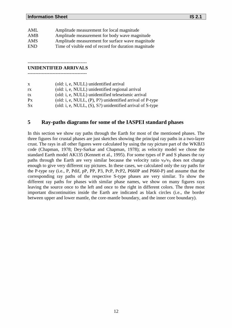
AML Amplitude measurement for local magnitude AMB Amplitude measurement for body wave magnitude AMS Amplitude measurement for surface wave magnitude END Time of visible end of record for duration magnitude -------------------------------------- UNIDENTIFIED ARRIVALS -------------------------------------- x (old: i, e, NULL) unidentified arrival rx (old: i, e, NULL) unidentified regional arrival tx (old: i, e, NULL) unidentified teleseismic arrival Px (old: i, e, NULL, (P), P?) unidentified arrival of P-type Sx (old: i, e, NULL, (S), S?) unidentified arrival of S-type 5 Ray-paths diagrams for some of the IASPEI standard phases In this section we show ray paths through the Earth for most of the mentioned phases. The three figures for crustal phases are just sketches showing the principal ray paths in a two-layer crust. The rays in all other figures were calculated by using the ray picture part of the WKBJ3 code (Chapman, 1978; Dey-Sarkar and Chapman, 1978); as velocity model we chose the standard Earth model AK135 (Kennett et al., 1995). For some types of P and S phases the ray paths through the Earth are very similar because the velocity ratio vP/vS does not change enough to give very different ray pictures. In these cases, we calculated only the ray paths for the P-type ray (i.e., P, Pdif, pP, PP, P3, PcP, PcP2, P660P and P660-P) and assume that the corresponding ray paths of the respective S-type phases are very similar. To show the different ray paths for phases with similar phase names, we show on many figures rays leaving the source once to the left and once to the right in different colors. The three most important discontinuities inside the Earth are indicated as black circles (i.e., the border between upper and lower mantle, the core-mantle boundary, and the inner core boundary).

Information Sheet IS 2.1
13
5.1 Seismic rays of crustal phases
a)
b)
c)
Figure 1 Seismic „crustal phases“ observed in the case of a two-layer crust in local and regional distance ranges (0° < D < about 20°) from the seismic source in the: a) upper crust; b) lower crust; and c) uppermost mantle.
Information Sheet IS 2.1
14
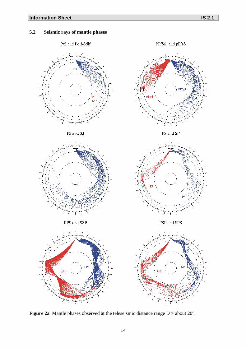
5.2 Seismic rays of mantle phases
Figure 2a Mantle phases observed at the teleseismic distance range D > about 20°.

Information Sheet IS 2.1
15
Figure 2b Reflections from the Earth’s core.
5.3 Seismic rays through the Earth’s core phases
Figure 3a Seismic rays of direct core phases.
Information Sheet IS 2.1
16
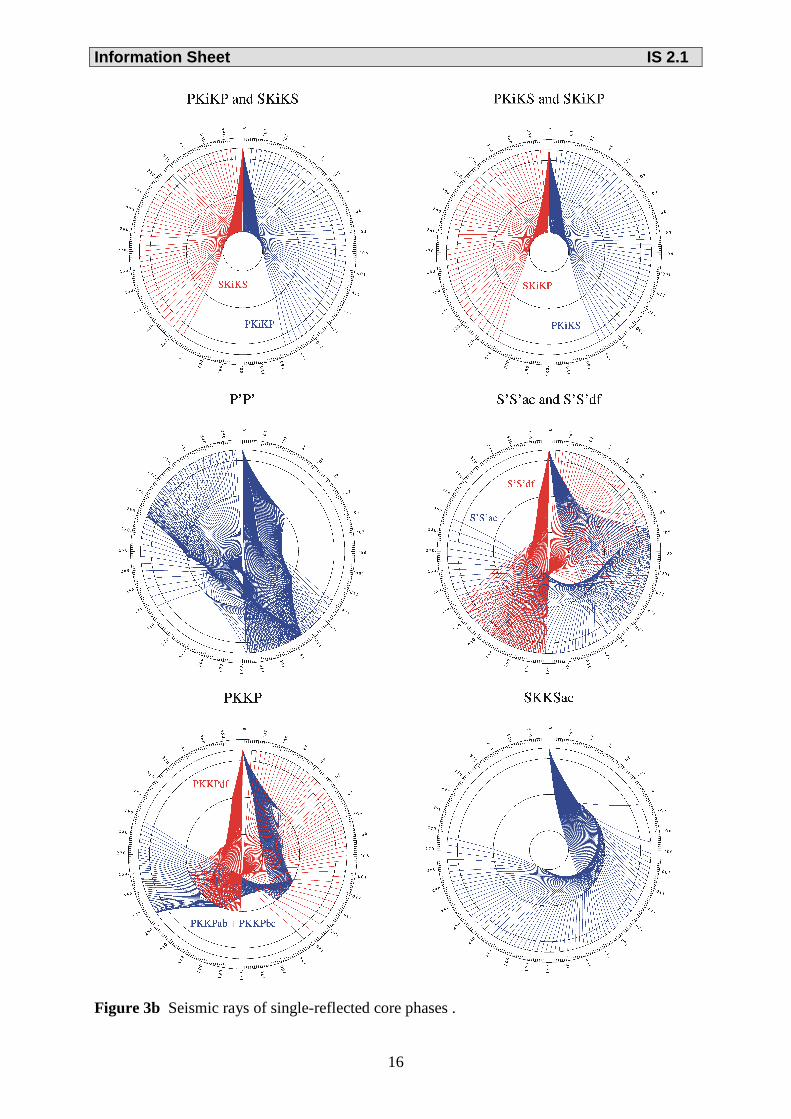
Figure 3b Seismic rays of single-reflected core phases .

Information Sheet IS 2.1
17
Figure 3c Seismic rays of multiple-reflected and converted core phases.

Information Sheet IS 2.1
18