topic bending
DESCRIPTION
Structural Steel DesignFlexural MembersIt contains Beam Loading & diagramTRANSCRIPT

Structural Steel DesignFlexural Members
Dr. Seshu Adluri
Flexural members -Dr. Seshu Adluri
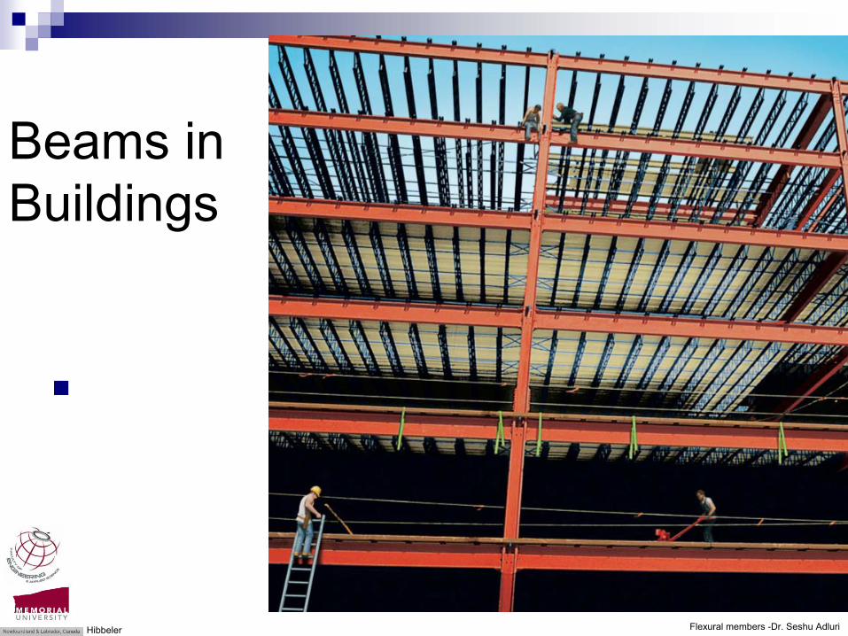
Beams in Buildings
Hibbeler

Flexural members -Dr. Seshu Adluri
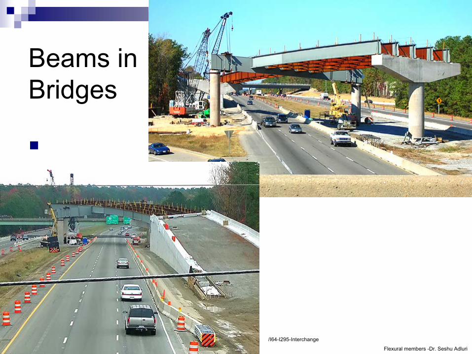
Beams in Bridges
Hibbeler; Wallarah Creek Bridge; eastbound on I-64, approaching I-295 overpasses
Flexural members -Dr. Seshu Adluri
Beams in Bridges
/I64-I295-Interchange
Flexural members -Dr. Seshu Adluri
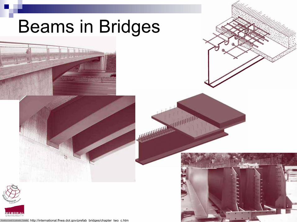
Beams in Bridges
http://international.fhwa.dot.gov/prefab_bridges/chapter_two_c.htm
Flexural members -Dr. Seshu Adluri
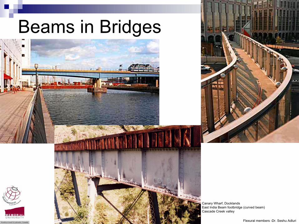
Beams in Bridges
Canary Wharf, DocklandsEast India Beam footbridge (curved beam)Cascade Creek valley

Flexural members -Dr. Seshu Adluri
Beam construction!
Now [Television (CSI) vanity] !
Then [engineering necessity]
Construction workers take a lunch break on a steel beam atop the RCA Building at Rockefeller Center, New York, Sept. 29, 1932. In the background is the Chrysler Building
The high-flying cast of 'CSI: NY's' fourth season 2007

Flexural members -Dr. Seshu Adluri
Beam construction!
Building the Empire State, 1930. Lewis Hine (two workers)
Building the Empire State, 1930. Lewis Hine (two workers)
Flexural members -Dr. Seshu Adluri
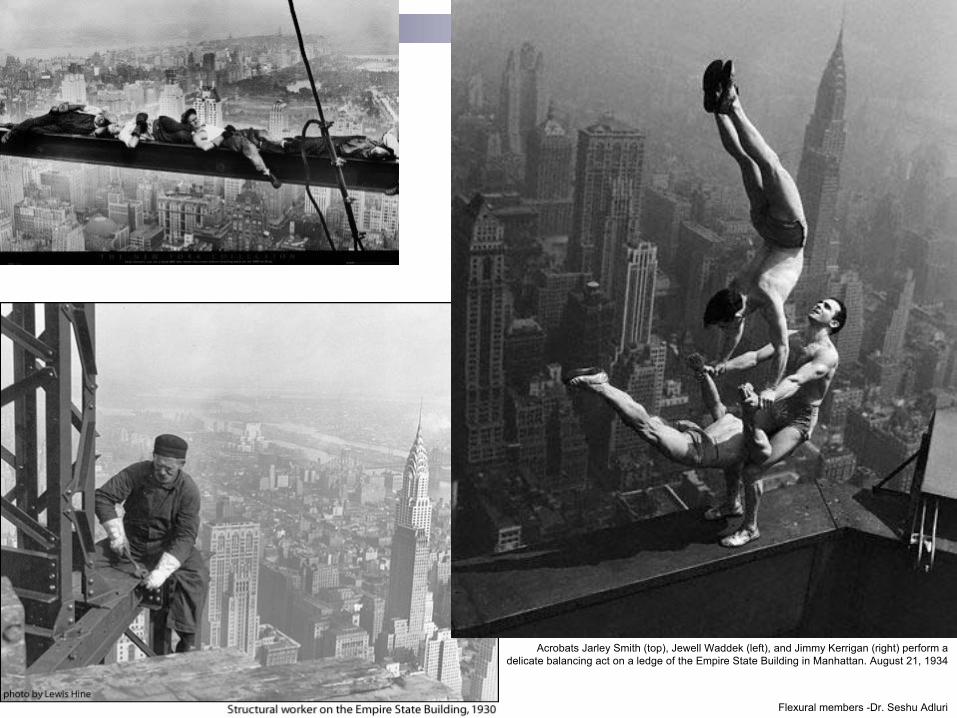
Beams!
Acrobats Jarley Smith (top), Jewell Waddek (left), and Jimmy Kerrigan (right) perform a delicate balancing act on a ledge of the Empire State Building in Manhattan. August 21, 1934
Flexural members -Dr. Seshu Adluri
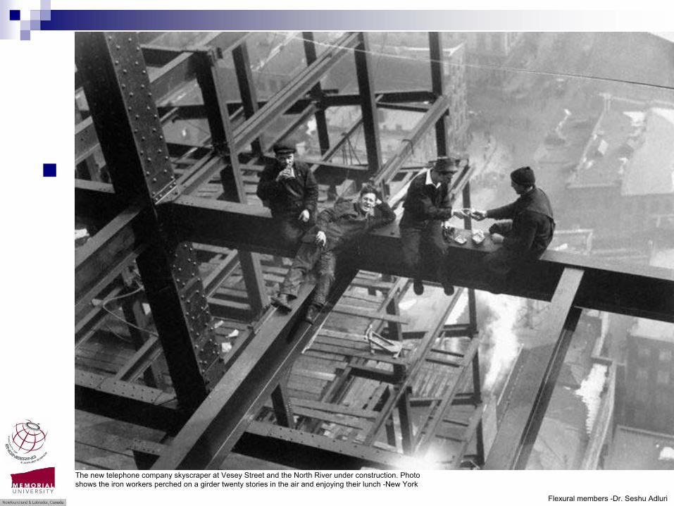
Beams!
The new telephone company skyscraper at Vesey Street and the North River under construction. Photo shows the iron workers perched on a girder twenty stories in the air and enjoying their lunch -New York

Flexural members -Dr. Seshu Adluri
Beam construction!
Construction workers eat their lunches atop a steel beam 800 feet above ground, at the building site of the RCA Building in Rockefeller Center, 1930’s

Flexural members -Dr. Seshu Adluri
Beam installation

Flexural members -Dr. Seshu Adluri
Beam profiles

Flexural members -Dr. Seshu Adluri
Beam geometry
Stand alone beamsFrame beams
Hibbeler

Flexural members -Dr. Seshu Adluri
Beam Loading
Hibbeler
Flexural members -Dr. Seshu Adluri
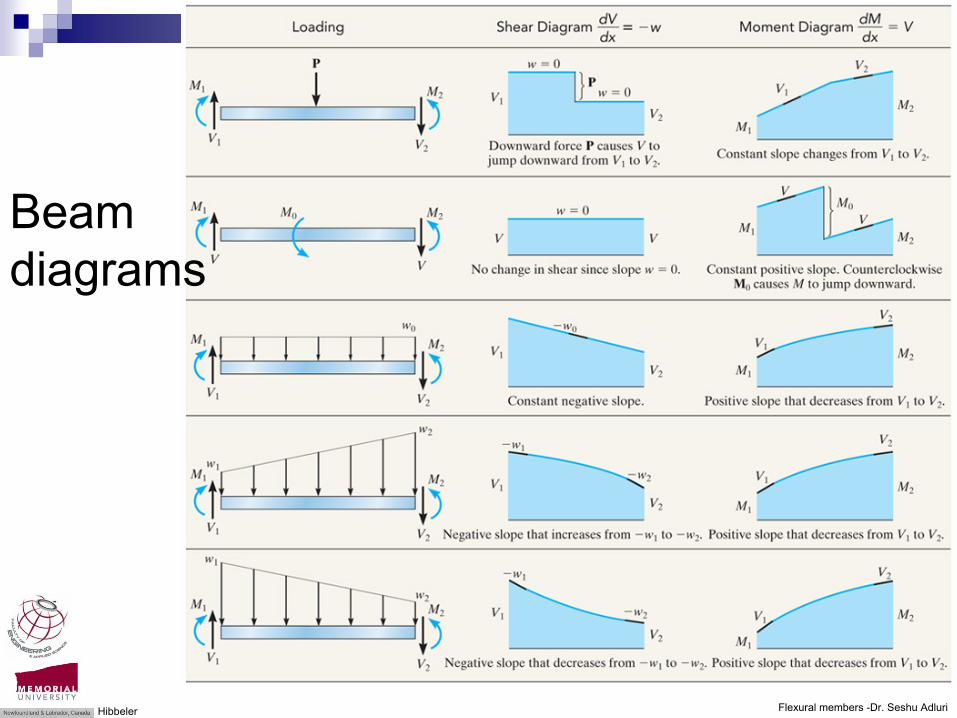
Beam diagrams
Hibbeler
Flexural members -Dr. Seshu Adluri
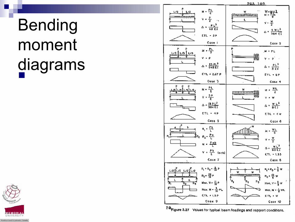
Bending moment diagrams
Flexural members -Dr. Seshu Adluri
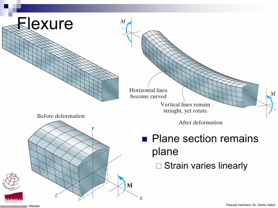
Flexure
Plane section remains plane
Strain varies linearly
Hibbeler

Flexural members -Dr. Seshu Adluri
Bending stress
Hibbeler

Flexural members -Dr. Seshu Adluri
Stress for yield moment MY
Hibbeler
Flexural members -Dr. Seshu Adluri
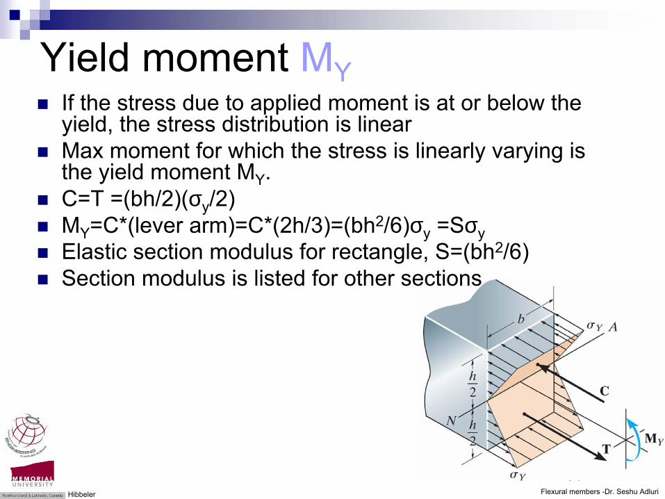
Yield moment MYIf the stress due to applied moment is at or below the yield, the stress distribution is linear Max moment for which the stress is linearly varying is the yield moment MY.C=T =(bh/2)(σy/2)MY=C*(lever arm)=C*(2h/3)=(bh2/6)σy =SσyElastic section modulus for rectangle, S=(bh2/6)Section modulus is listed for other sections
Hibbeler

Flexural members -Dr. Seshu Adluri
Stress for moment M>MY
Hibbeler
Flexural members -Dr. Seshu Adluri
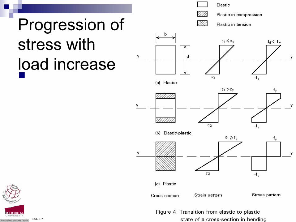
Progression of stress with load increase
ESDEP
Flexural members -Dr. Seshu Adluri
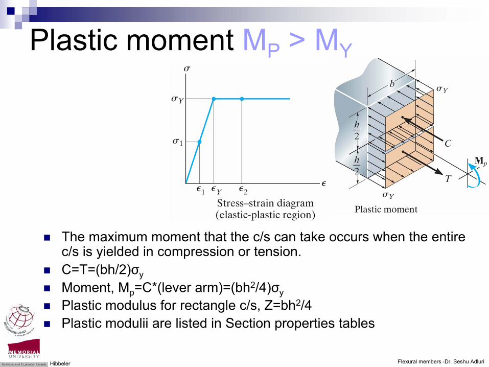
Plastic moment MP > MY
The maximum moment that the c/s can take occurs when the entire c/s is yielded in compression or tension. C=T=(bh/2)σyMoment, Mp=C*(lever arm)=(bh2/4)σyPlastic modulus for rectangle c/s, Z=bh2/4Plastic modulii are listed in Section properties tables
Hibbeler

Flexural members -Dr. Seshu Adluri
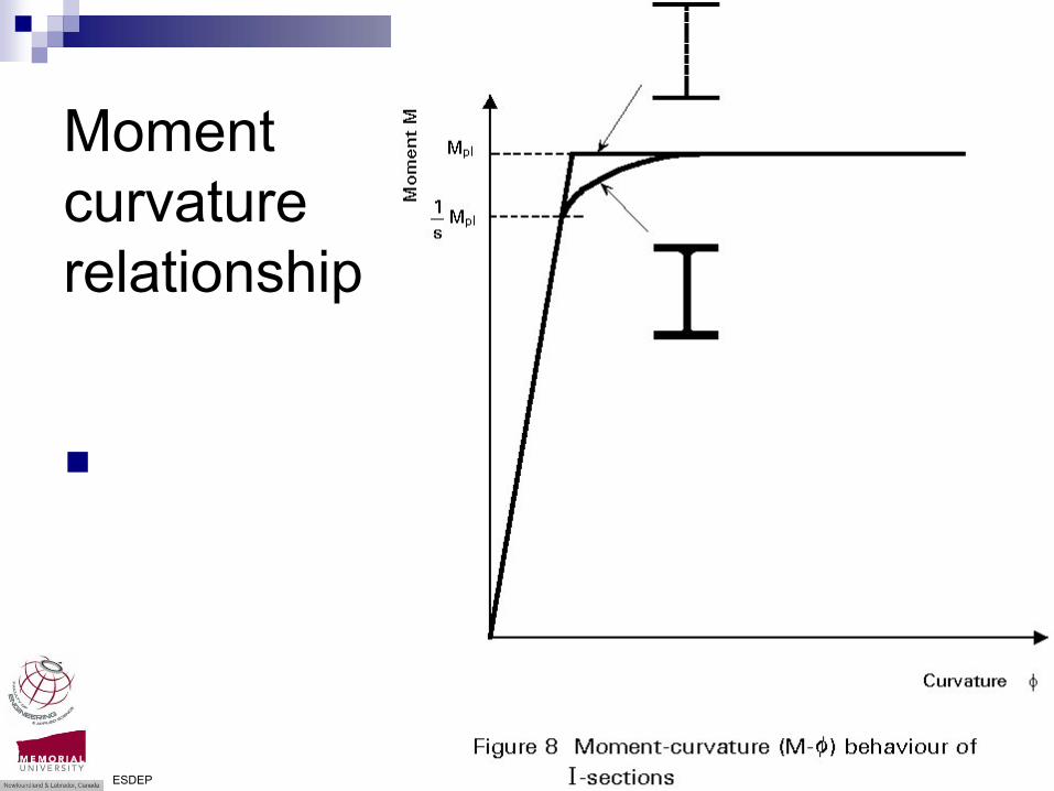
Moment curvature relationship
ESDEP
Flexural members -Dr. Seshu Adluri
Moment curvature relationship
ESDEP

Flexural members -Dr. Seshu Adluri
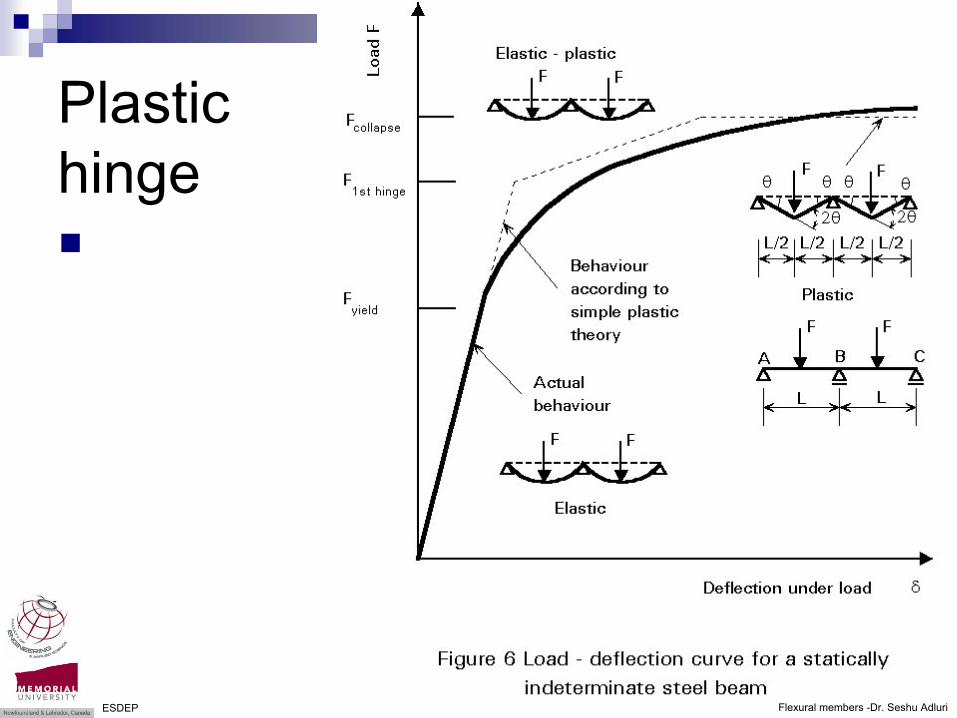
Plastic hinge
ESDEP
Flexural members -Dr. Seshu Adluri
Plastic hinge
ESDEP

Flexural members -Dr. Seshu Adluri
Beams in Shear
Hibbeler

Flexural members -Dr. Seshu Adluri
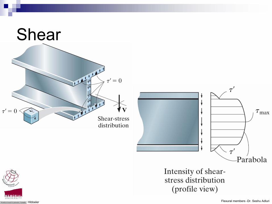
Shear
Hibbeler
Flexural members -Dr. Seshu Adluri
Shear
Hibbeler

Flexural members -Dr. Seshu Adluri
Shear flow
Hibbeler

Flexural members -Dr. Seshu Adluri
Shear flow
Hibbeler

Flexural members -Dr. Seshu Adluri
Shear flow
Hibbeler

Flexural members -Dr. Seshu Adluri
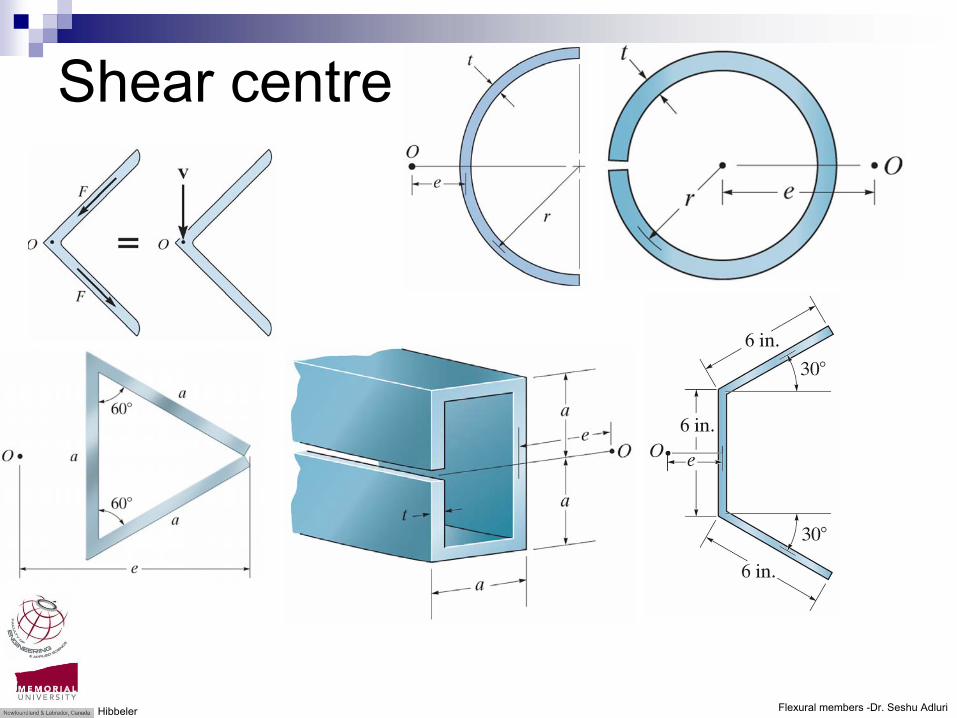
Shear centre
Hibbeler
Flexural members -Dr. Seshu Adluri
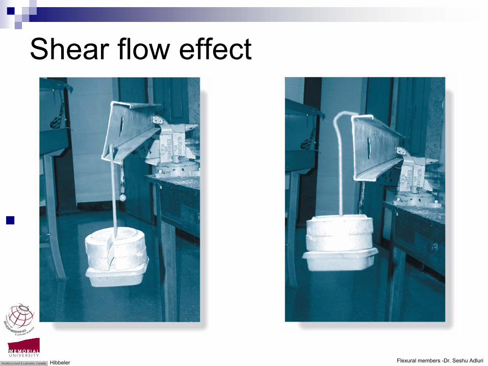
Shear flow effect
Hibbeler
Flexural members -Dr. Seshu Adluri
Shear centre
Hibbeler

Flexural members -Dr. Seshu Adluri
Shear centre
Hibbeler
Flexural members -Dr. Seshu Adluri
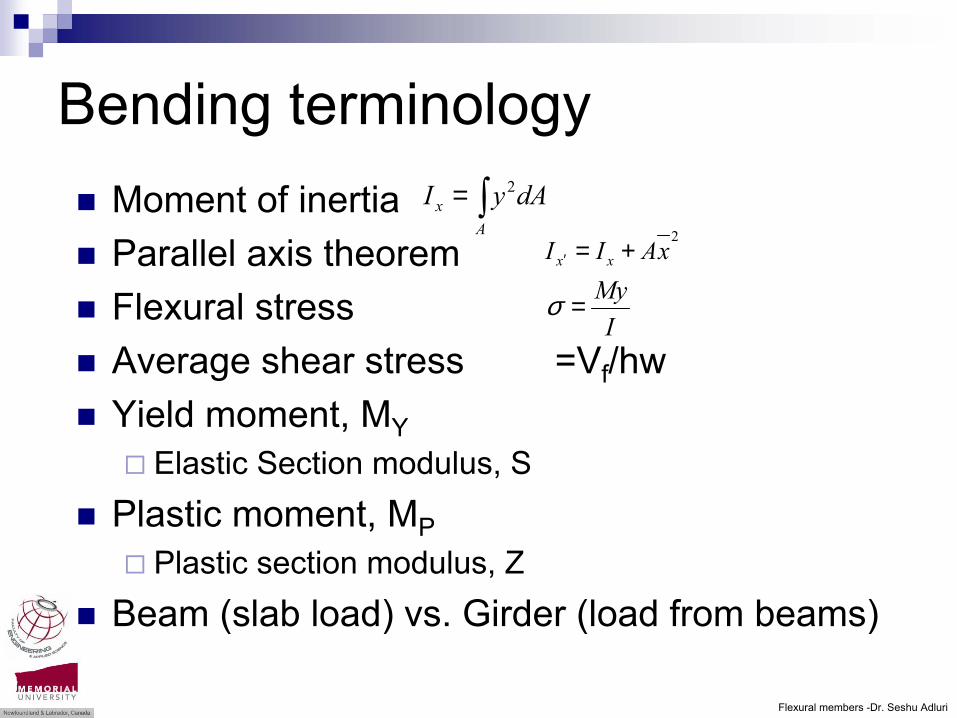
Bending terminologyMoment of inertiaParallel axis theoremFlexural stressAverage shear stress =Vf/hwYield moment, MY
Elastic Section modulus, SPlastic moment, MP
Plastic section modulus, Z Beam (slab load) vs. Girder (load from beams)
∫=A
x dAyI 2
MyI
σ =
2xAII xx +=′

Flexural members -Dr. Seshu Adluri
Beams and Girders
Steel flexural membersBeams in building framesElements carrying lateral loadsEquipment, etc.
Useful in pure bending as well as in beam-columnsDesign Clauses: CAN/CSA-S16
Bending strength as per Clauses 13.5, 6 & 7Shear strength as per Clause 13.4 Local buckling check: Clause 11 (Table 2)Special provisions: Clause 14Deflection limits: Appendix D
Flexural members -Dr. Seshu Adluri
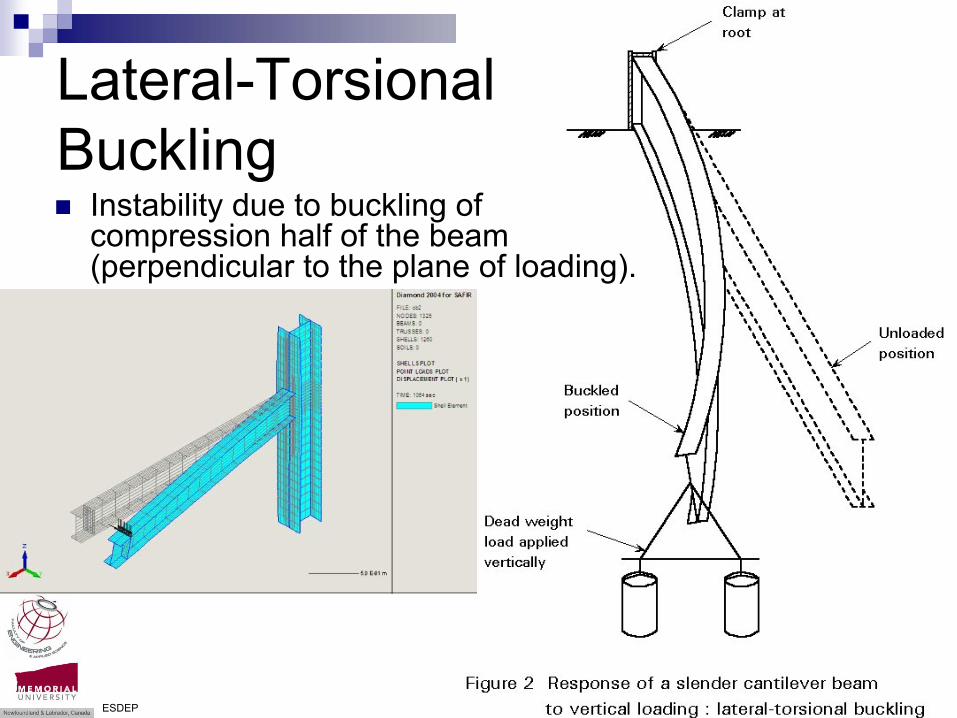
Lateral-Torsional Buckling
Instability due to buckling of compression half of the beam (perpendicular to the plane of loading).
ESDEP

Flexural members -Dr. Seshu Adluri
Lateral-Torsional Buckling
Instability due to buckling of compression half of the beam (perpendicular to the plane of loading).
ESDEP

Flexural members -Dr. Seshu Adluri
Lateral-Torsional Buckling
ESDEP

Flexural members -Dr. Seshu Adluri
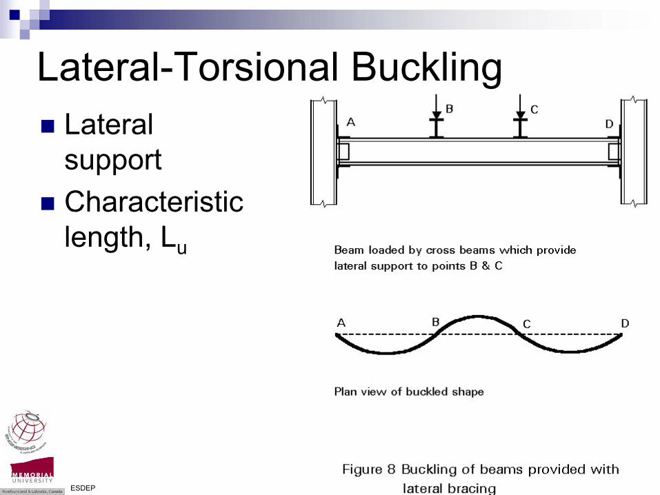
Lateral supportCharacteristic length, Lu
Lateral-Torsional Buckling
Flexural members -Dr. Seshu Adluri
Lateral supportCharacteristic length, Lu
Lateral-Torsional Buckling
ESDEP
Flexural members -Dr. Seshu Adluri
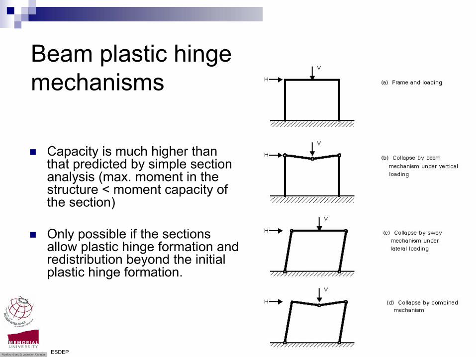
Beam plastic hinge mechanisms
Capacity is much higher than that predicted by simple section analysis (max. moment in the structure < moment capacity of the section)
Only possible if the sections allow plastic hinge formation and redistribution beyond the initial plastic hinge formation.
ESDEP

Flexural members -Dr. Seshu Adluri
M
M
M
Mpl
Mpl
Mpl
Mel
Mel
Localbuckling
Localbuckling
Localbuckling
φ
φ
φ
Model ofBehaviour
MomentResistance
Rotation Capacity Class
Plastic momenton full section
Plastic momenton full section
fy
fy
Elastic momenton full section
Elastic moment oneffective section
fy
fy
M
Mpl
1
1
1
1
Localbuckling
φφ
φ
φ
φ
φrot
M
M
M
M
φpl
φpl
φpl
φpl
φpl
Mpl
Mpl
Mpl
Mpl
Mal
Mpl
Sufficient
Limited
None
None
1
1
1
1
1
2
3
4
Classification of beams
ESDEP
Flexural members -Dr. Seshu Adluri
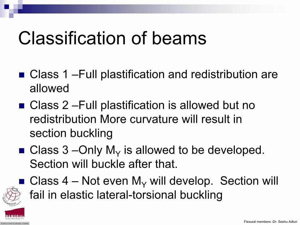
Classification of beams
Class 1 –Full plastification and redistribution are allowedClass 2 –Full plastification is allowed but no redistribution More curvature will result in section buckling Class 3 –Only MY is allowed to be developed. Section will buckle after that.Class 4 – Not even MY will develop. Section will fail in elastic lateral-torsional buckling

Flexural members -Dr. Seshu Adluri
Plate buckling
Different types of buckling depending on
b/t ratio Webs and flanges have different limitsend conditions for plate segmentsUse Table 2 for beams and beam-columns
ESDEP
Flexural members -Dr. Seshu Adluri
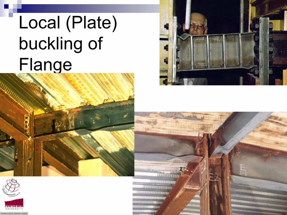
Local (Plate) buckling of Flange
Flexural members -Dr. Seshu Adluri
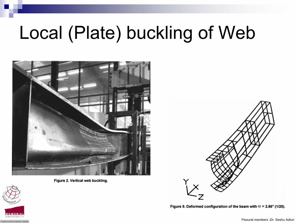
Local (Plate) buckling of Web

Flexural members -Dr. Seshu Adluri
Web buckling

Flexural members -Dr. Seshu Adluri
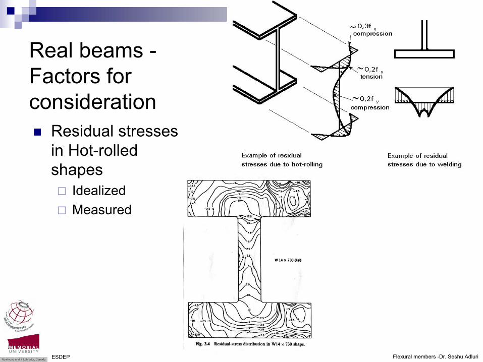
Real beams -Factors for consideration
Residual stresses in Hot-rolled shapes (idealized)
Flexural members -Dr. Seshu Adluri
Real beams -Factors for consideration
Residual stresses in Hot-rolled shapes
Idealized Measured
ESDEP
Flexural members -Dr. Seshu Adluri
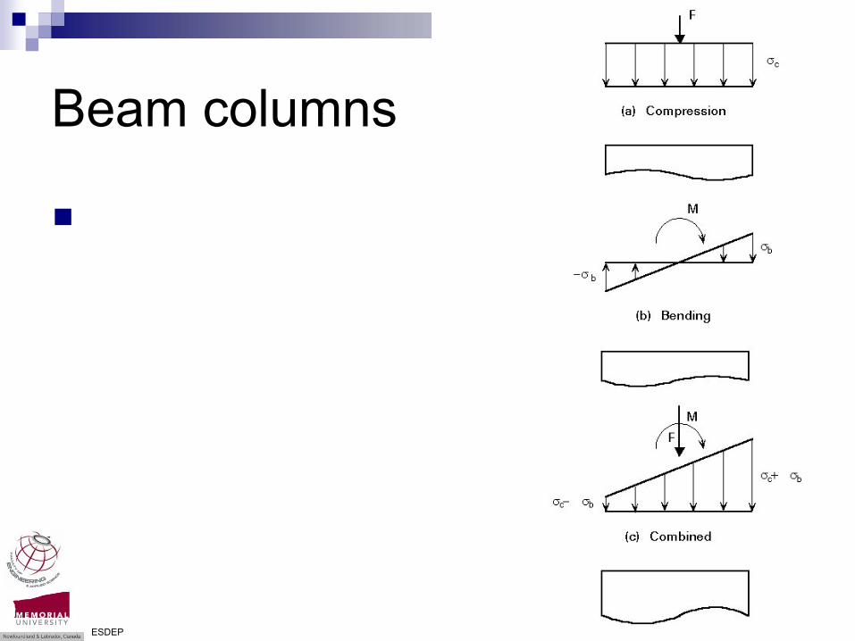
Beam columns
ESDEP
Flexural members -Dr. Seshu Adluri
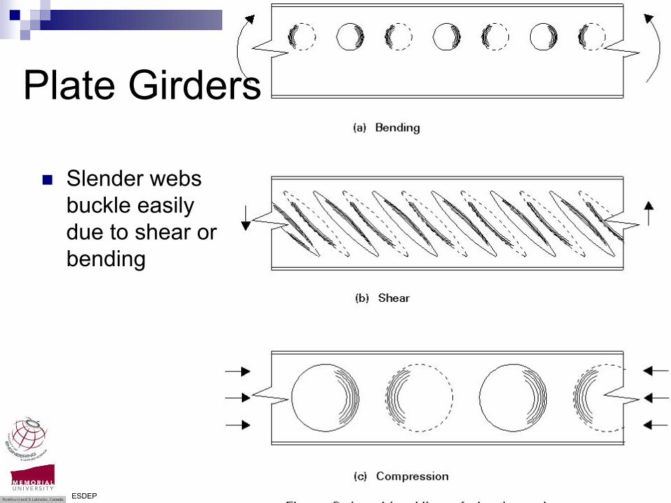
Slender webs buckle easily due to shear or bending
Plate Girders
ESDEP

Flexural members -Dr. Seshu Adluri
Slender webs buckle easily due to shear or bending
Use reduced effective c/s
orUse reduced capacity
Plate Girders
ESDEP

Flexural members -Dr. Seshu Adluri
Stiffeners are Important
June 1970, Milford Haven bridge over the River Cleddau in the UK

Flexural members -Dr. Seshu Adluri
ReferencesHibbeler, R.C. Mechanics of Materials, 7th Ed., Prentice Hallhttp://www.esdep.org/members/samplecourse/toc.htmhttp://www.roadstothefuture.com/I64-I295-Interchange-Mod.htmlwww.rta.nsw.gov.au/cgi-bin/index.cgi?action=heritage.show&id=4305021http://international.fhwa.dot.gov/prefab_bridges/chapter_two_c.htmhttp://www.bardaglea.org.uk/bridges/bridge-types/bridge-types-beam.htmlhttp://ghostdepot.com/rg/bridges/stl_tres/stl_tres.htmhttp://www.playlsi.com/Products/SportsandFitness/CurvedBalanceBeam/http://www.monorails.org/tmspages/switch.htmlhttp://www.galinsky.com/buildings/savill/index.htmlhttp://911research.wtc7.net/mirrors/guardian2/fire/SCI.htmhttp://911research.wtc7.net/mirrors/guardian2/fire/SLamont.htmhttp://www.scielo.br/scielo.php?script=sci_arttext&pid=S0100-73862001000400003&lng=es&nrm=iso&tlng=eshttp://www.ce.jhu.edu/steel/lecture/compression/res_stress_1.jpghttp://www.longtain.com/en/2_prod/tech.htmhttp://www.istructe.org/technical/db/index.asp?page=281&bhcp=1
Most of the pictures in the preceding were gathered from various sources. To the extent possible, the source has been indicated at the bottom of the slides. The text and some of the figures are done by the instructor, Dr. Seshu Adluri. No copy right for pictures that have been obtained from other sources is claimed or implied by the instructor. The material is for class room instruction only.