tools for design using autocad and autodesk inventor … · 18-2 tools for design using autocad and...
TRANSCRIPT
Tools for Design Using AutoCAD and Autodesk Inventor 18-1
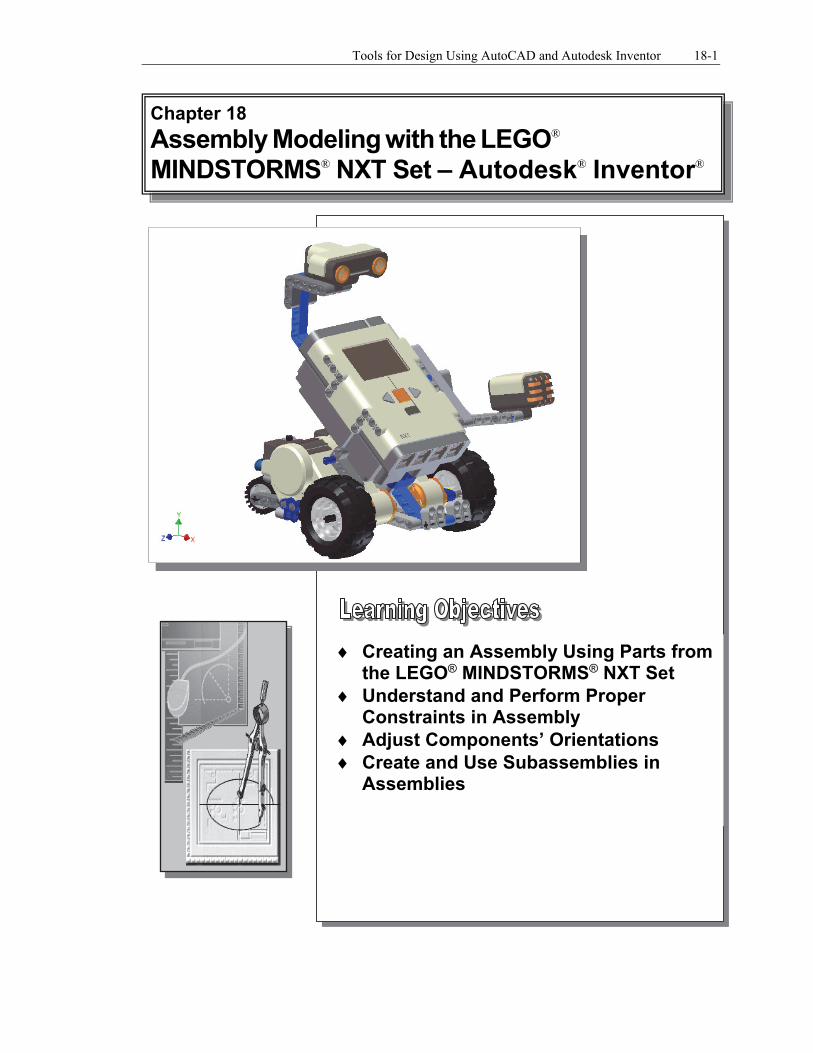
Creating an Assembly Using Parts from the LEGO® MINDSTORMS® NXT Set
Understand and Perform Proper Constraints in Assembly
Adjust Components’ Orientations Create and Use Subassemblies in
Assemblies
Chapter 18 Assembly Modeling with the LEGO®
MINDSTORMS® NXT Set – Autodesk® Inventor®
18-2 Tools for Design Using AutoCAD and Autodesk Inventor
Introduction
The rapid development in computer hardware technology, during the past few decades, has brought many changes in the practice of engineering in general. Many areas that were traditionally identified as electrical engineering or mechanical engineering are now multidisciplinary, integrating digital electronics, kinematics analysis, and computing together. Additionally, the use of microcontrollers and embedded systems has become inevitable in almost every engineering field. Given these developments, engineering education has also witnessed significant changes, such as adapting to project-oriented courses that emphasize real world applications, and the use of new educational tools such as robot kits.
The use of robot kits provides many benefits, through assembling, building, and following instructions, which help develop fine motor skills and hand-eye coordination. Students are exposed to multiple subjects such as mechanics, electronics, and programming. By working together to create robots that perform exciting challenges, students also gain valuable critical thinking, problem-solving and team-building skills. Students can also participate in several national/world robot competitions held annually, which can provide a strong sense of accomplishment.
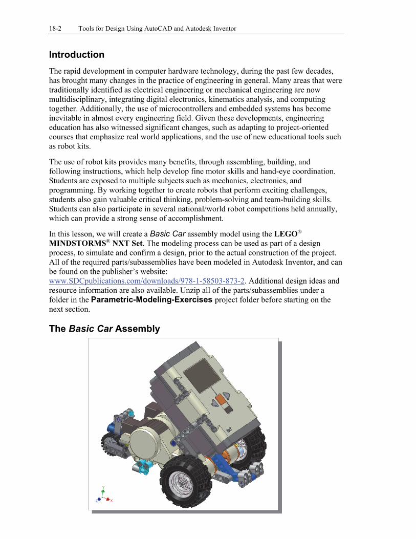
In this lesson, we will create a Basic Car assembly model using the LEGO® MINDSTORMS® NXT Set. The modeling process can be used as part of a design process, to simulate and confirm a design, prior to the actual construction of the project. All of the required parts/subassemblies have been modeled in Autodesk Inventor, and can be found on the publisher’s website: www.SDCpublications.com/downloads/978-1-58503-873-2. Additional design ideas and resource information are also available. Unzip all of the parts/subassemblies under a folder in the Parametric-Modeling-Exercises project folder before starting on the next section. The Basic Car Assembly
Assembly Modeling with the LEGO® MINDSTORMS® NXT Set – Autodesk Inventor 18-3
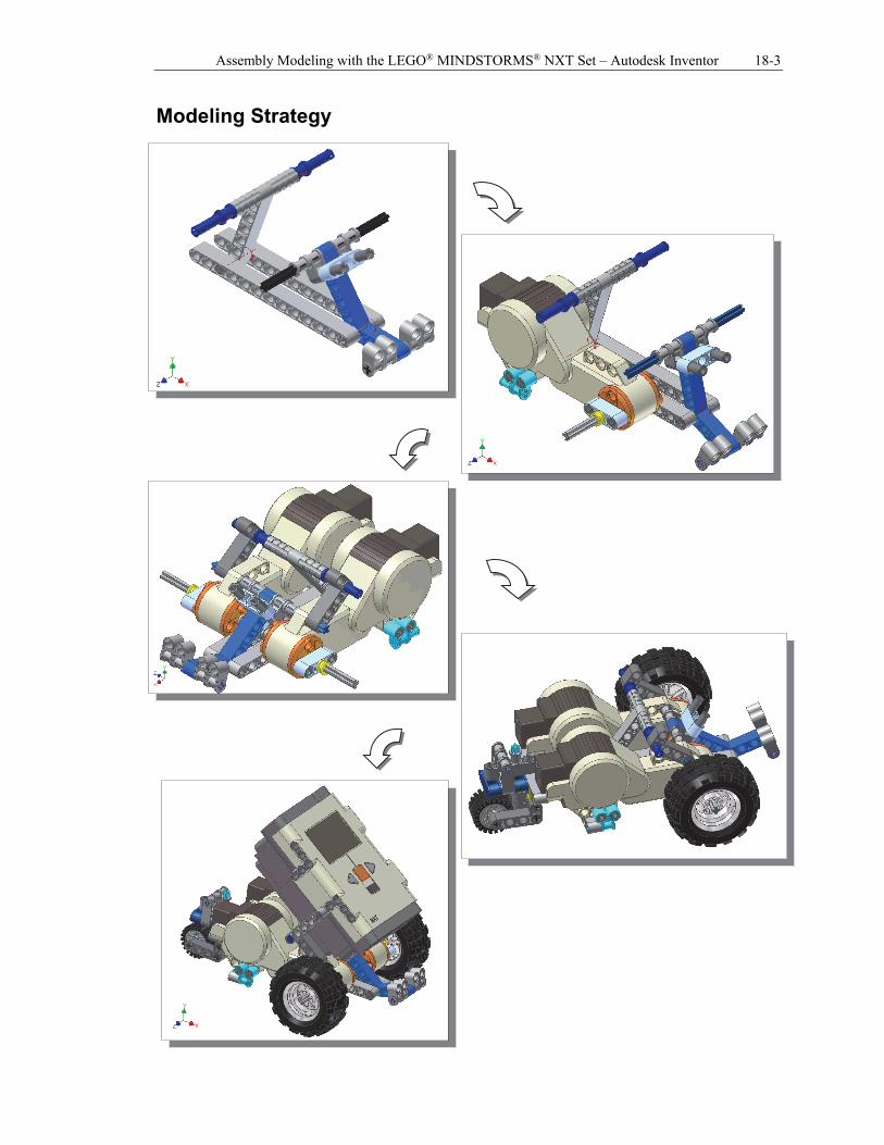
Modeling Strategy
18-4 Tools for Design Using AutoCAD and Autodesk Inventor
Starting Autodesk Inventor
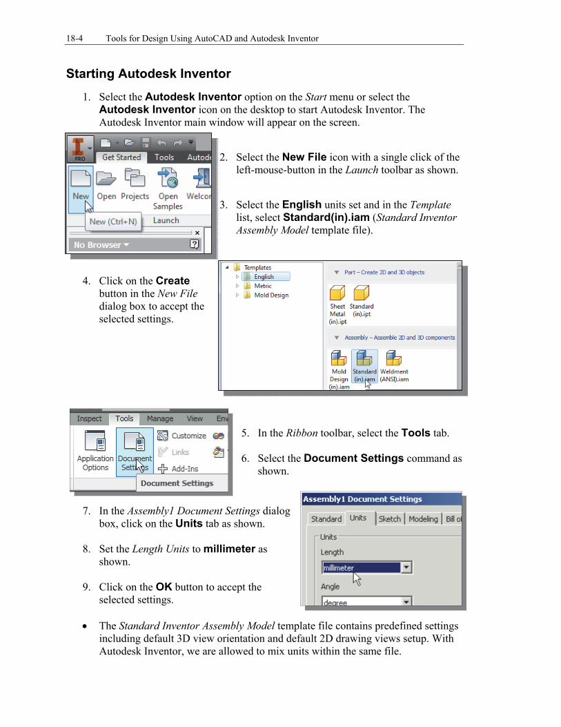
1. Select the Autodesk Inventor option on the Start menu or select the Autodesk Inventor icon on the desktop to start Autodesk Inventor. The Autodesk Inventor main window will appear on the screen.
2. Select the New File icon with a single click of the
left-mouse-button in the Launch toolbar as shown.
3. Select the English units set and in the Template
list, select Standard(in).iam (Standard Inventor Assembly Model template file).
4. Click on the Create button in the New File dialog box to accept the selected settings.
5. In the Ribbon toolbar, select the Tools tab. 6. Select the Document Settings command as
shown.
7. In the Assembly1 Document Settings dialog
box, click on the Units tab as shown. 8. Set the Length Units to millimeter as
shown. 9. Click on the OK button to accept the
selected settings.
The Standard Inventor Assembly Model template file contains predefined settings including default 3D view orientation and default 2D drawing views setup. With Autodesk Inventor, we are allowed to mix units within the same file.
Assembly Modeling with the LEGO® MINDSTORMS® NXT Set – Autodesk Inventor 18-5
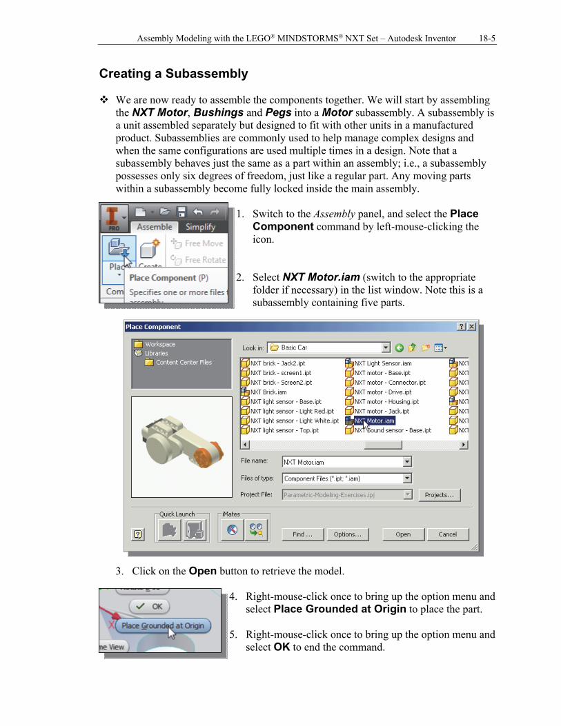
Creating a Subassembly We are now ready to assemble the components together. We will start by assembling
the NXT Motor, Bushings and Pegs into a Motor subassembly. A subassembly is a unit assembled separately but designed to fit with other units in a manufactured product. Subassemblies are commonly used to help manage complex designs and when the same configurations are used multiple times in a design. Note that a subassembly behaves just the same as a part within an assembly; i.e., a subassembly possesses only six degrees of freedom, just like a regular part. Any moving parts within a subassembly become fully locked inside the main assembly.
1. Switch to the Assembly panel, and select the Place
Component command by left-mouse-clicking the icon.
2. Select NXT Motor.iam (switch to the appropriate
folder if necessary) in the list window. Note this is a subassembly containing five parts.
3. Click on the Open button to retrieve the model.
4. Right-mouse-click once to bring up the option menu and
select Place Grounded at Origin to place the part. 5. Right-mouse-click once to bring up the option menu and
select OK to end the command.
18-6 Tools for Design Using AutoCAD and Autodesk Inventor
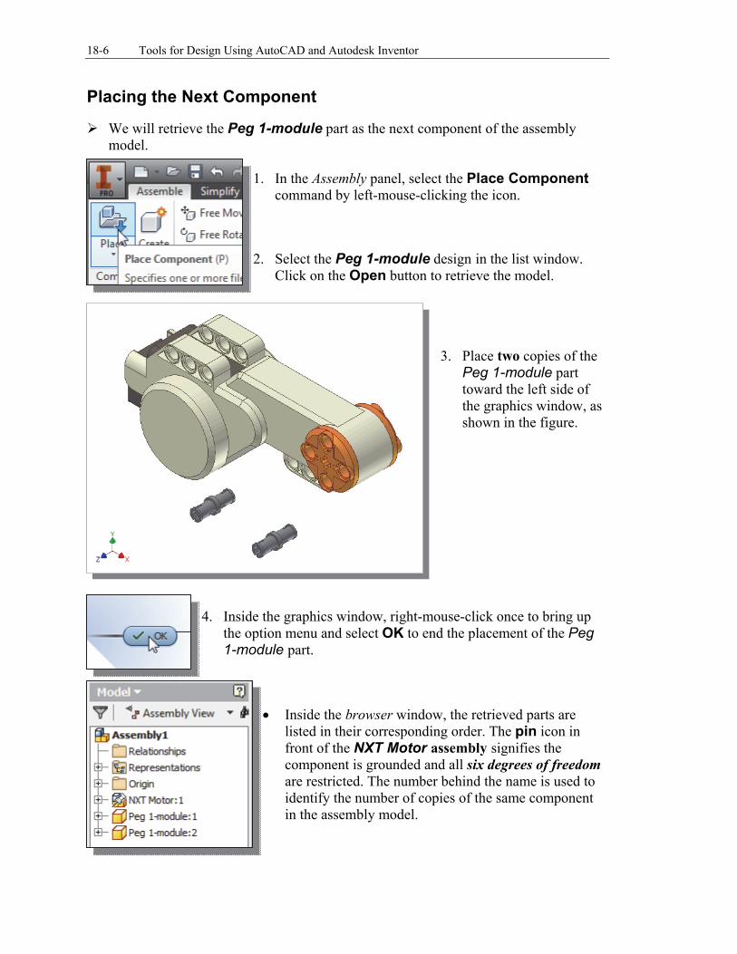
Placing the Next Component We will retrieve the Peg 1-module part as the next component of the assembly
model. 1. In the Assembly panel, select the Place Component
command by left-mouse-clicking the icon. 2. Select the Peg 1-module design in the list window.
Click on the Open button to retrieve the model.
3. Place two copies of the
Peg 1-module part toward the left side of the graphics window, as shown in the figure.
4. Inside the graphics window, right-mouse-click once to bring up the option menu and select OK to end the placement of the Peg 1-module part.
Inside the browser window, the retrieved parts are listed in their corresponding order. The pin icon in front of the NXT Motor assembly signifies the component is grounded and all six degrees of freedom are restricted. The number behind the name is used to identify the number of copies of the same component in the assembly model.

Assembly Modeling with the LEGO® MINDSTORMS® NXT Set – Autodesk Inventor 18-7
Degrees of Freedom Display Each component in an assembly has six degrees of freedom (DOF), or ways in
which rigid 3D bodies can move: movement along the X-, Y-, and Z-axes (translational freedom), plus rotation around the X-, Y-, and Z-axes (rotational freedom). Translational DOFs allow the part to move in the direction of the specified vector. Rotational DOFs allow the part to turn about the specified axis.
Select the Degrees of Freedom option in the
View tab to display the DOF of the unconstrained component.
In parametric modeling, the degrees of freedom symbol shows the remaining degrees of freedom (both translational and rotational) for the components of the active assembly. Note that each component has its own degrees of freedom, even if the same part is placed multiple times within the same assembly. The assembly constraints are also applied independently to each component. The set of degrees of freedom symbols, as shown in the figure above, signifies each copy of the Peg 1-module is unconstrained and should be constrained independently.
Translational DOF Rotational DOF
18-8 Tools for Design Using AutoCAD and Autodesk Inventor
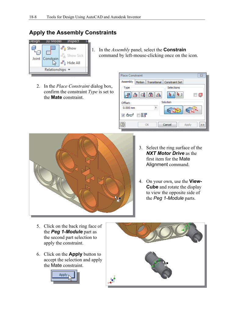
Apply the Assembly Constraints 1. In the Assembly panel, select the Constrain
command by left-mouse-clicking once on the icon.
2. In the Place Constraint dialog box, confirm the constraint Type is set to the Mate constraint.
3. Select the ring surface of the NXT Motor Drive as the first item for the Mate Alignment command.
4. On your own, use the View-
Cube and rotate the display to view the opposite side of the Peg 1-Module parts.
5. Click on the back ring face of
the Peg 1-Module part as the second part selection to apply the constraint.
6. Click on the Apply button to accept the selection and apply the Mate constraint.
Assembly Modeling with the LEGO® MINDSTORMS® NXT Set – Autodesk Inventor 18-9
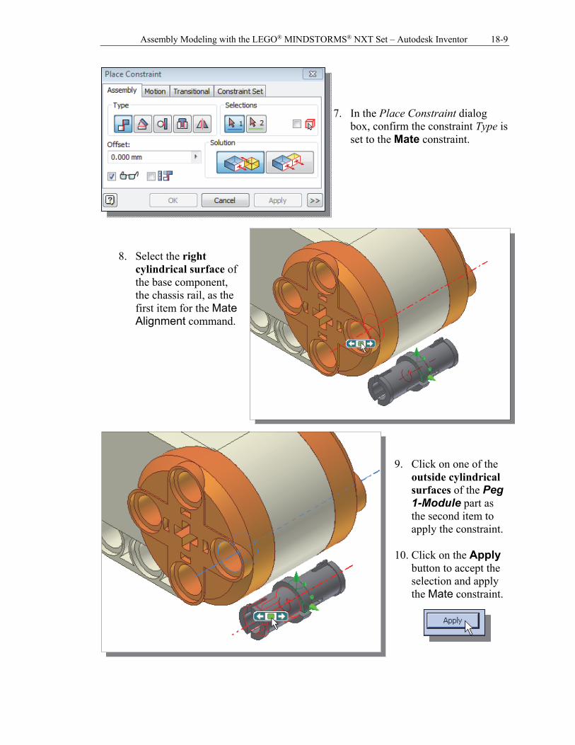
7. In the Place Constraint dialog
box, confirm the constraint Type is set to the Mate constraint.
8. Select the right cylindrical surface of the base component, the chassis rail, as the first item for the Mate Alignment command.
9. Click on one of the
outside cylindrical surfaces of the Peg 1-Module part as the second item to apply the constraint.
10. Click on the Apply
button to accept the selection and apply the Mate constraint.

18-10 Tools for Design Using AutoCAD and Autodesk Inventor
11. On your own, repeat the above steps and constrain the other Peg 1-Module as shown.
Note there is still one rotational
degree of freedom available.
12. In the Assembly panel, select the Place Component
command by left-mouse-clicking the icon. 13. Select the Beam 3-Module design in the list window.
Click on the Open button to retrieve the model.
14. Place one copy of the Beam 3-Module toward the left side of the graphics window, as shown in the figure.
15. Inside the graphics window, right-mouse-click once to bring up the option menu and select Done to end the command.
Assembly Modeling with the LEGO® MINDSTORMS® NXT Set – Autodesk Inventor 18-11
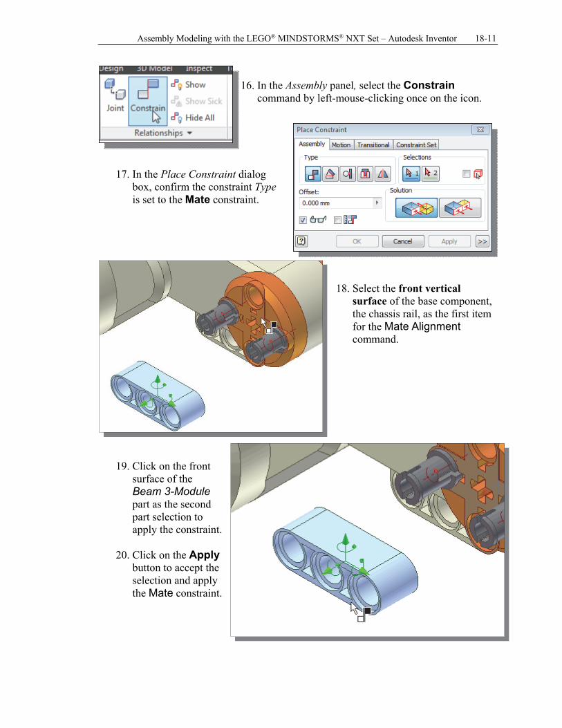
16. In the Assembly panel, select the Constrain
command by left-mouse-clicking once on the icon.
17. In the Place Constraint dialog
box, confirm the constraint Type is set to the Mate constraint.
18. Select the front vertical
surface of the base component, the chassis rail, as the first item for the Mate Alignment command.
19. Click on the front surface of the Beam 3-Module part as the second part selection to apply the constraint.
20. Click on the Apply button to accept the selection and apply the Mate constraint.
18-12 Tools for Design Using AutoCAD and Autodesk Inventor
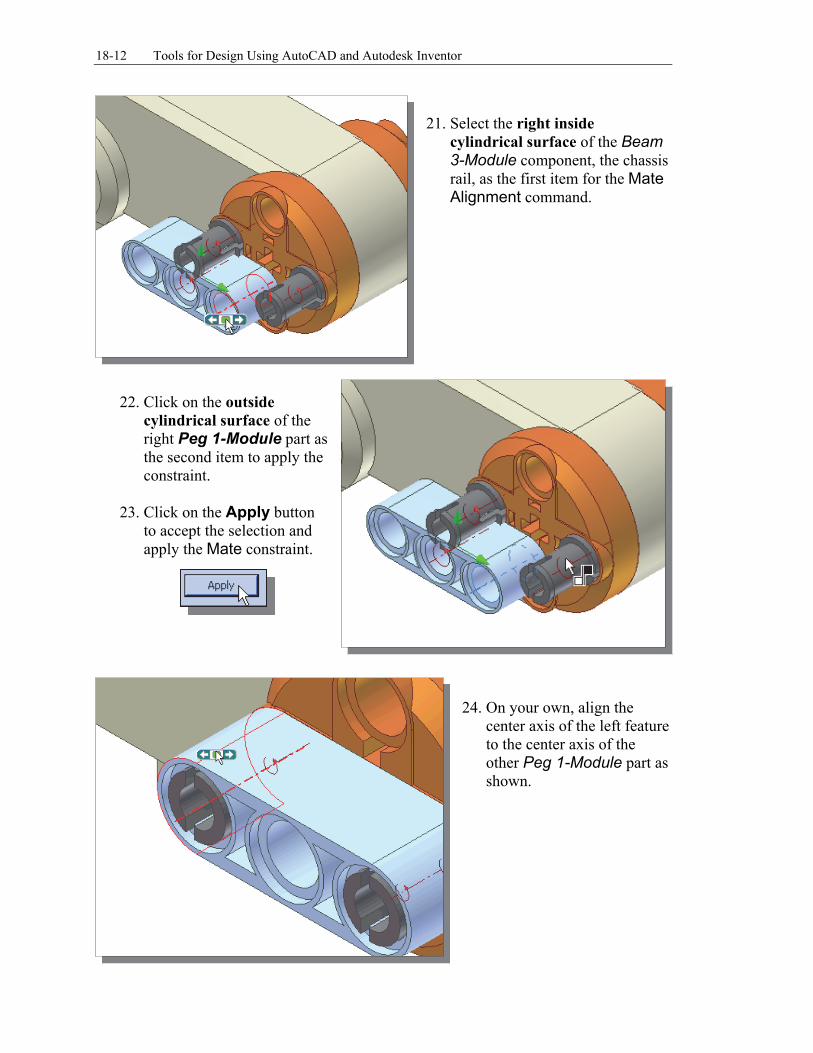
21. Select the right inside
cylindrical surface of the Beam 3-Module component, the chassis rail, as the first item for the Mate Alignment command.
22. Click on the outside
cylindrical surface of the right Peg 1-Module part as the second item to apply the constraint.
23. Click on the Apply button to accept the selection and apply the Mate constraint.
24. On your own, align the
center axis of the left feature to the center axis of the other Peg 1-Module part as shown.
Assembly Modeling with the LEGO® MINDSTORMS® NXT Set – Autodesk Inventor 18-13
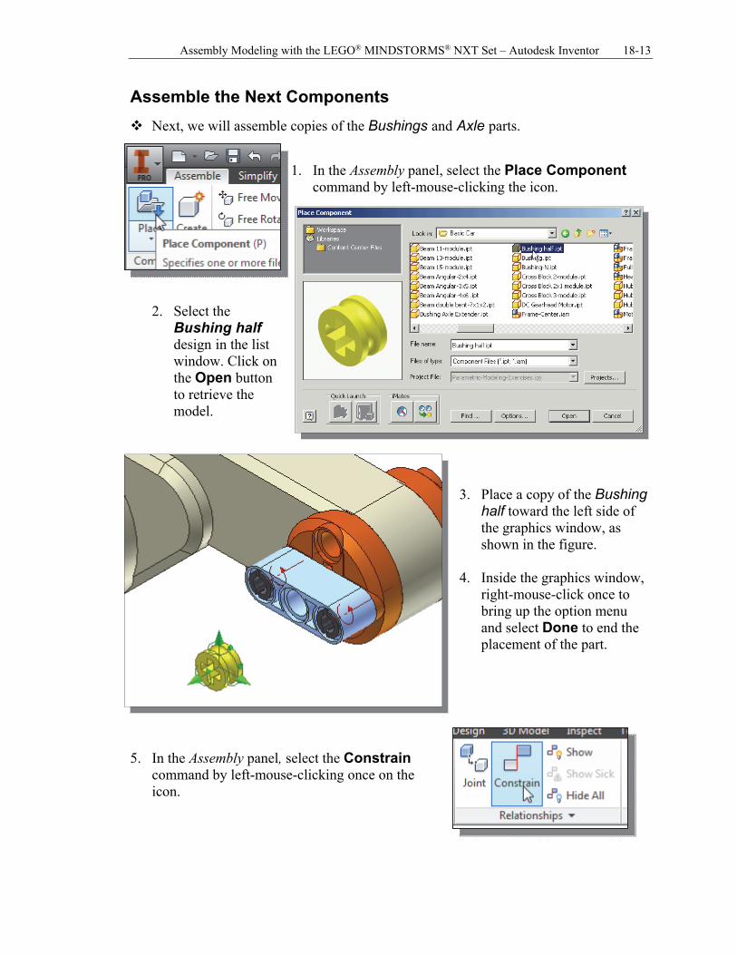
Assemble the Next Components
Next, we will assemble copies of the Bushings and Axle parts.
1. In the Assembly panel, select the Place Component command by left-mouse-clicking the icon.
2. Select the Bushing half design in the list window. Click on the Open button to retrieve the model.
3. Place a copy of the Bushing
half toward the left side of the graphics window, as shown in the figure.
4. Inside the graphics window,
right-mouse-click once to bring up the option menu and select Done to end the placement of the part.
5. In the Assembly panel, select the Constrain
command by left-mouse-clicking once on the icon.
18-14 Tools for Design Using AutoCAD and Autodesk Inventor
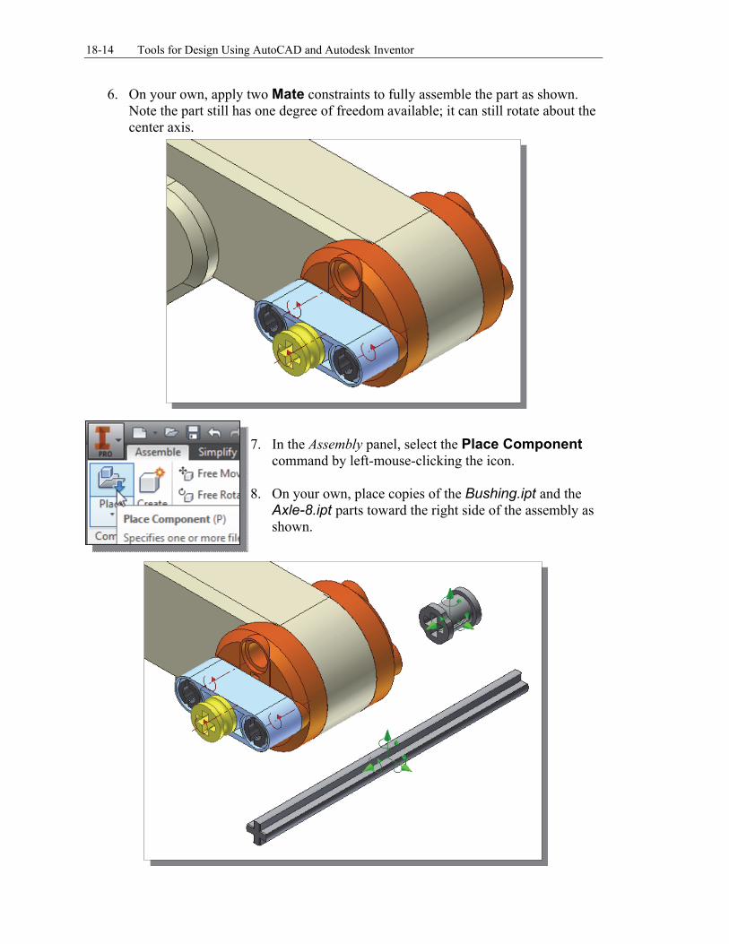
6. On your own, apply two Mate constraints to fully assemble the part as shown. Note the part still has one degree of freedom available; it can still rotate about the center axis.
7. In the Assembly panel, select the Place Component
command by left-mouse-clicking the icon. 8. On your own, place copies of the Bushing.ipt and the
Axle-8.ipt parts toward the right side of the assembly as shown.
Assembly Modeling with the LEGO® MINDSTORMS® NXT Set – Autodesk Inventor 18-15
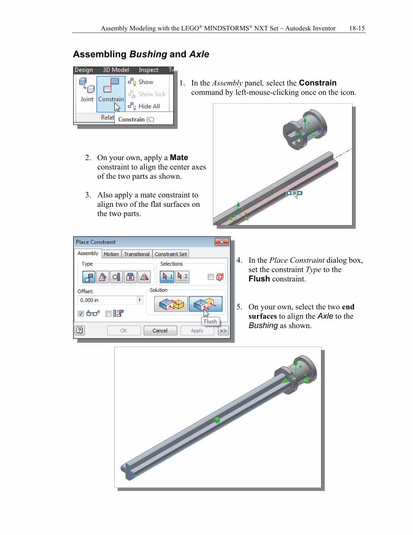
Assembling Bushing and Axle 1. In the Assembly panel, select the Constrain
command by left-mouse-clicking once on the icon.
2. On your own, apply a Mate constraint to align the center axes of the two parts as shown.
3. Also apply a mate constraint to align two of the flat surfaces on the two parts.
4. In the Place Constraint dialog box,
set the constraint Type to the Flush constraint.
5. On your own, select the two end
surfaces to align the Axle to the Bushing as shown.
18-16 Tools for Design Using AutoCAD and Autodesk Inventor
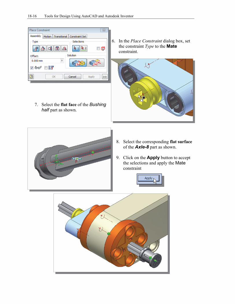
6. In the Place Constraint dialog box, set
the constraint Type to the Mate constraint.
7. Select the flat face of the Bushing half part as shown.
8. Select the corresponding flat surface
of the Axle-8 part as shown. 9. Click on the Apply button to accept
the selections and apply the Mate constraint
Assembly Modeling with the LEGO® MINDSTORMS® NXT Set – Autodesk Inventor 18-17
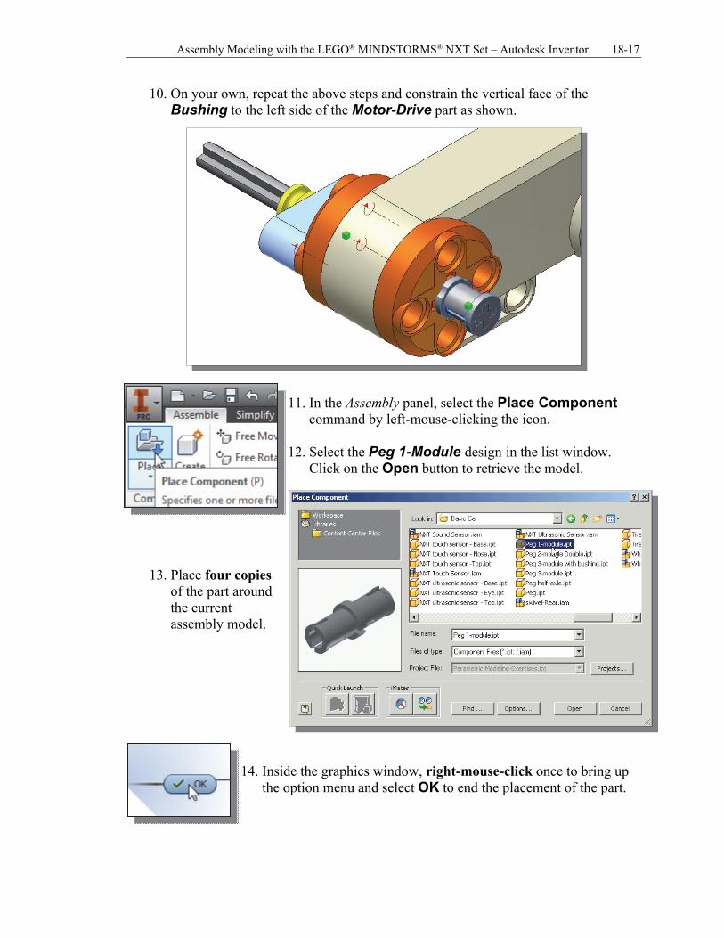
10. On your own, repeat the above steps and constrain the vertical face of the Bushing to the left side of the Motor-Drive part as shown.
11. In the Assembly panel, select the Place Component
command by left-mouse-clicking the icon. 12. Select the Peg 1-Module design in the list window.
Click on the Open button to retrieve the model.
13. Place four copies of the part around the current assembly model.
14. Inside the graphics window, right-mouse-click once to bring up
the option menu and select OK to end the placement of the part.
18-18 Tools for Design Using AutoCAD and Autodesk Inventor
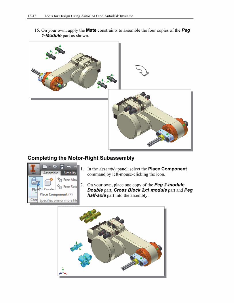
15. On your own, apply the Mate constraints to assemble the four copies of the Peg 1-Module part as shown.
Completing the Motor-Right Subassembly
1. In the Assembly panel, select the Place Component
command by left-mouse-clicking the icon. 2. On your own, place one copy of the Peg 2-module
Double part, Cross Block 2x1 module part and Peg half-axle part into the assembly.
Assembly Modeling with the LEGO® MINDSTORMS® NXT Set – Autodesk Inventor 18-19
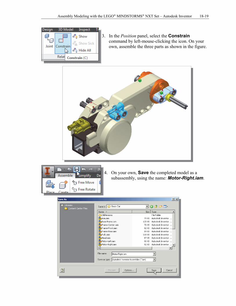
3. In the Position panel, select the Constrain
command by left-mouse-clicking the icon. On your own, assemble the three parts as shown in the figure.
4. On your own, Save the completed model as a
subassembly, using the name: Motor-Right.iam.
18-20 Tools for Design Using AutoCAD and Autodesk Inventor
Starting the Main Assembly
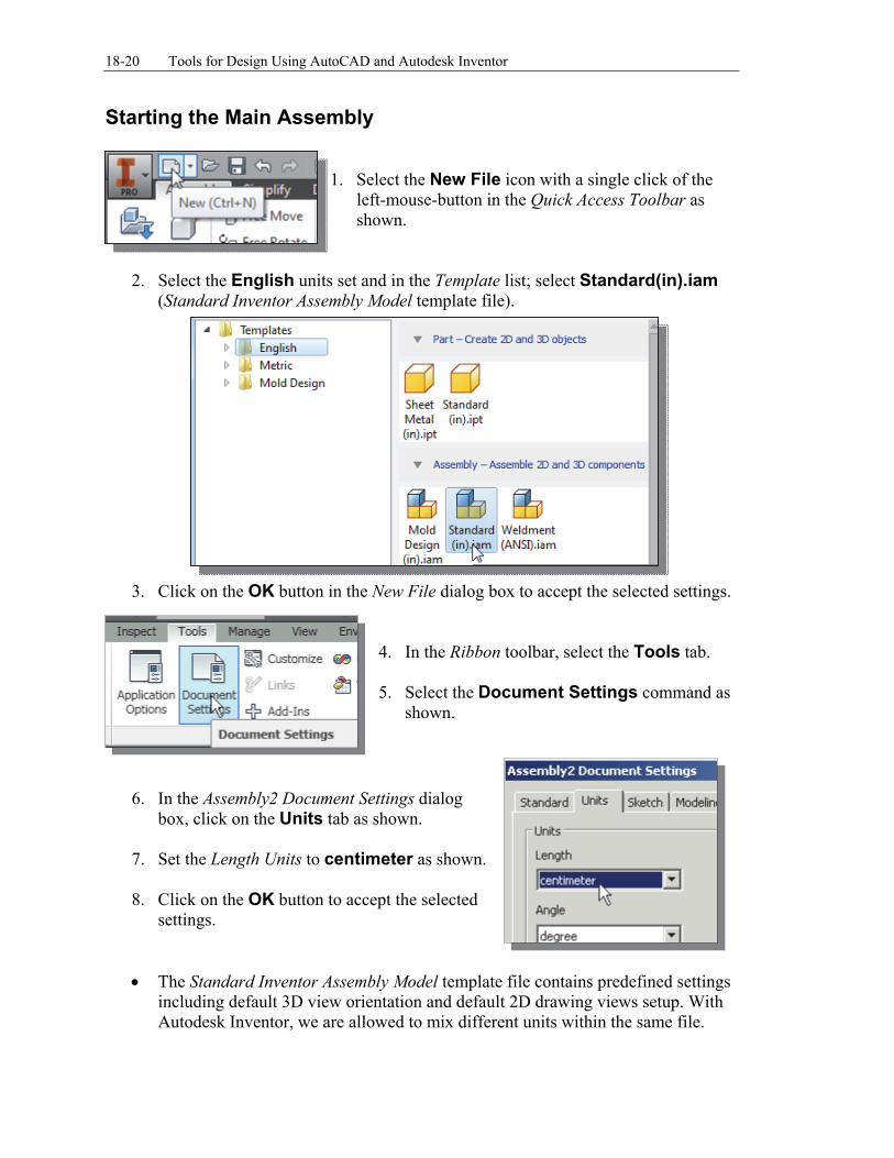
1. Select the New File icon with a single click of the
left-mouse-button in the Quick Access Toolbar as shown.
2. Select the English units set and in the Template list; select Standard(in).iam
(Standard Inventor Assembly Model template file).
3. Click on the OK button in the New File dialog box to accept the selected settings. 4. In the Ribbon toolbar, select the Tools tab. 5. Select the Document Settings command as
shown.
6. In the Assembly2 Document Settings dialog box, click on the Units tab as shown.
7. Set the Length Units to centimeter as shown. 8. Click on the OK button to accept the selected
settings.
The Standard Inventor Assembly Model template file contains predefined settings including default 3D view orientation and default 2D drawing views setup. With Autodesk Inventor, we are allowed to mix different units within the same file.
Assembly Modeling with the LEGO® MINDSTORMS® NXT Set – Autodesk Inventor 18-21
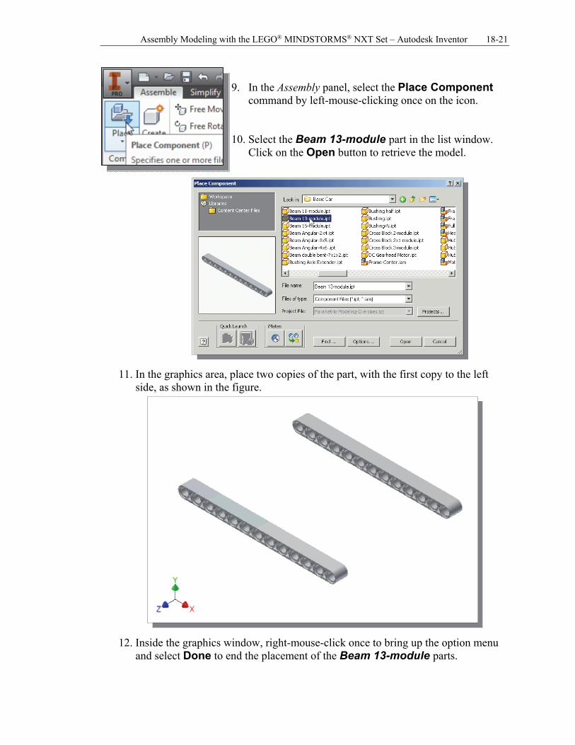
9. In the Assembly panel, select the Place Component
command by left-mouse-clicking once on the icon. 10. Select the Beam 13-module part in the list window.
Click on the Open button to retrieve the model.
11. In the graphics area, place two copies of the part, with the first copy to the left
side, as shown in the figure.
12. Inside the graphics window, right-mouse-click once to bring up the option menu
and select Done to end the placement of the Beam 13-module parts.
18-22 Tools for Design Using AutoCAD and Autodesk Inventor
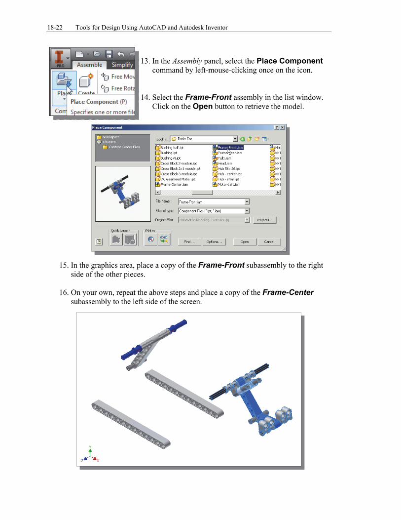
13. In the Assembly panel, select the Place Component
command by left-mouse-clicking once on the icon. 14. Select the Frame-Front assembly in the list window.
Click on the Open button to retrieve the model.
15. In the graphics area, place a copy of the Frame-Front subassembly to the right
side of the other pieces.
16. On your own, repeat the above steps and place a copy of the Frame-Center subassembly to the left side of the screen.
Assembly Modeling with the LEGO® MINDSTORMS® NXT Set – Autodesk Inventor 18-23
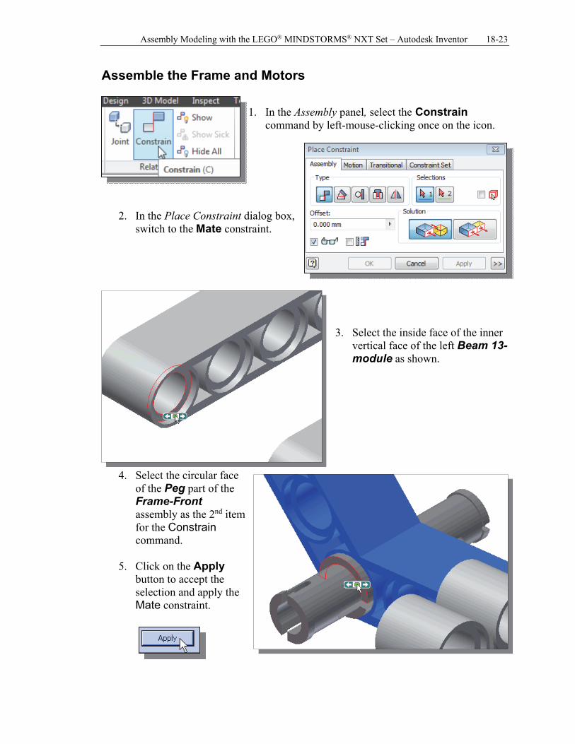
Assemble the Frame and Motors
1. In the Assembly panel, select the Constrain command by left-mouse-clicking once on the icon.
2. In the Place Constraint dialog box, switch to the Mate constraint.
3. Select the inside face of the inner
vertical face of the left Beam 13-module as shown.
4. Select the circular face of the Peg part of the Frame-Front assembly as the 2nd item for the Constrain command.
5. Click on the Apply button to accept the selection and apply the Mate constraint.
18-24 Tools for Design Using AutoCAD and Autodesk Inventor
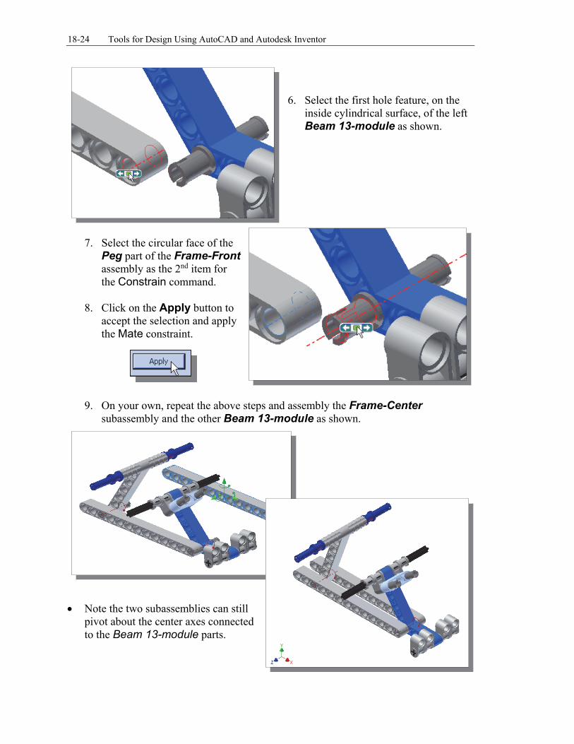
6. Select the first hole feature, on the
inside cylindrical surface, of the left Beam 13-module as shown.
7. Select the circular face of the
Peg part of the Frame-Front assembly as the 2nd item for the Constrain command.
8. Click on the Apply button to accept the selection and apply the Mate constraint.
9. On your own, repeat the above steps and assembly the Frame-Center subassembly and the other Beam 13-module as shown.
Note the two subassemblies can still
pivot about the center axes connected to the Beam 13-module parts.
Assembly Modeling with the LEGO® MINDSTORMS® NXT Set – Autodesk Inventor 18-25
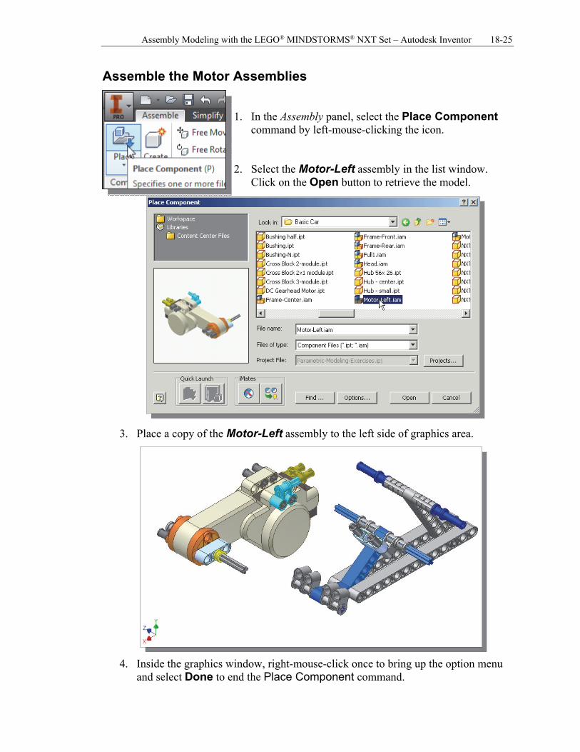
Assemble the Motor Assemblies 1. In the Assembly panel, select the Place Component
command by left-mouse-clicking the icon. 2. Select the Motor-Left assembly in the list window.
Click on the Open button to retrieve the model.
3. Place a copy of the Motor-Left assembly to the left side of graphics area.
4. Inside the graphics window, right-mouse-click once to bring up the option menu and select Done to end the Place Component command.
18-26 Tools for Design Using AutoCAD and Autodesk Inventor
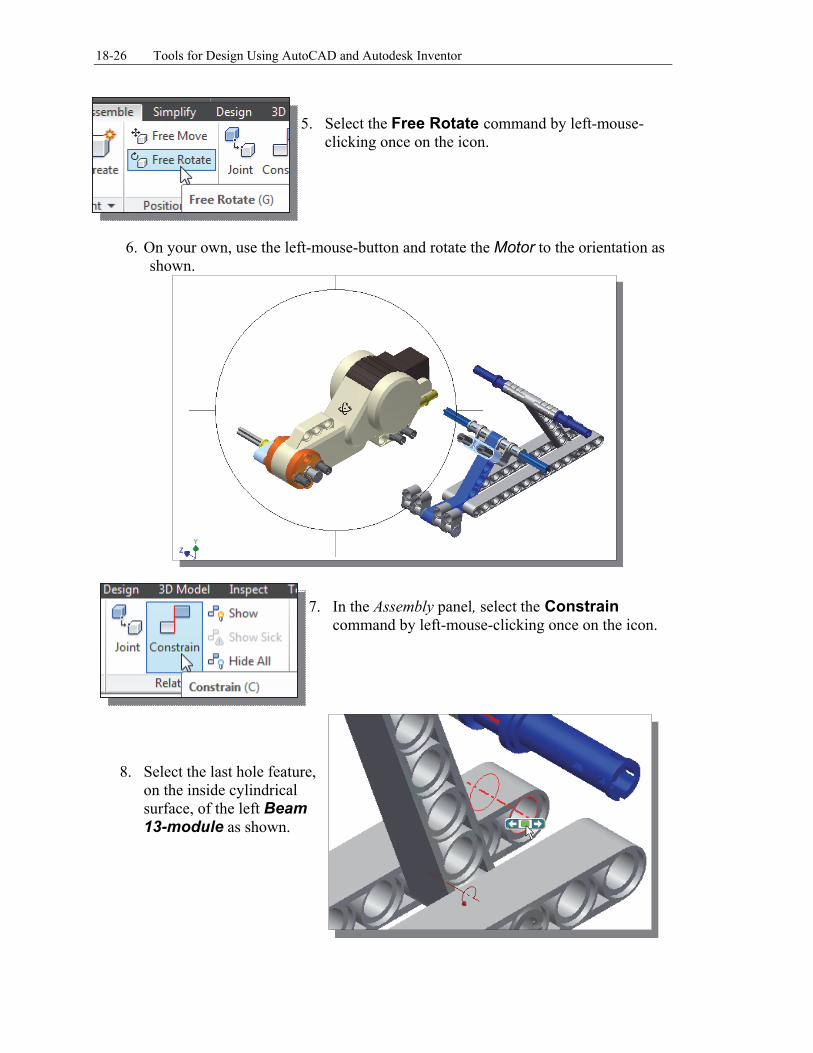
5. Select the Free Rotate command by left-mouse-
clicking once on the icon.
6. On your own, use the left-mouse-button and rotate the Motor to the orientation as
shown.
7. In the Assembly panel, select the Constrain
command by left-mouse-clicking once on the icon.
8. Select the last hole feature, on the inside cylindrical surface, of the left Beam 13-module as shown.
Assembly Modeling with the LEGO® MINDSTORMS® NXT Set – Autodesk Inventor 18-27
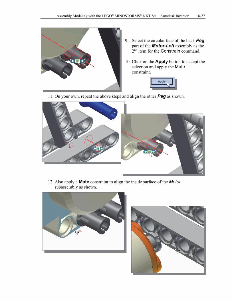
9. Select the circular face of the back Peg
part of the Motor-Left assembly as the 2nd item for the Constrain command.
10. Click on the Apply button to accept the
selection and apply the Mate constraint.
11. On your own, repeat the above steps and align the other Peg as shown.
12. Also apply a Mate constraint to align the inside surface of the Motor
subassembly as shown.
18-28 Tools for Design Using AutoCAD and Autodesk Inventor
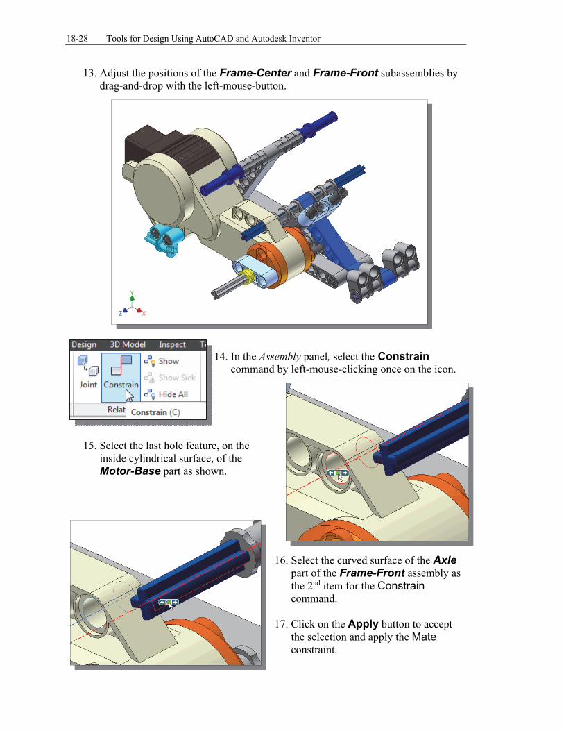
13. Adjust the positions of the Frame-Center and Frame-Front subassemblies by drag-and-drop with the left-mouse-button.
14. In the Assembly panel, select the Constrain
command by left-mouse-clicking once on the icon.
15. Select the last hole feature, on the
inside cylindrical surface, of the Motor-Base part as shown.
16. Select the curved surface of the Axle
part of the Frame-Front assembly as the 2nd item for the Constrain command.
17. Click on the Apply button to accept
the selection and apply the Mate constraint.
Assembly Modeling with the LEGO® MINDSTORMS® NXT Set – Autodesk Inventor 18-29
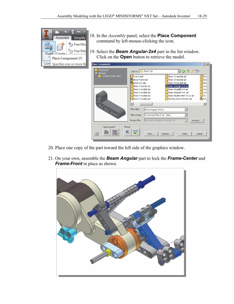
18. In the Assembly panel, select the Place Component
command by left-mouse-clicking the icon. 19. Select the Beam Angular-2x4 part in the list window.
Click on the Open button to retrieve the model.
20. Place one copy of the part toward the left side of the graphics window.
21. On your own, assemble the Beam Angular part to lock the Frame-Center and
Frame-Front in place as shown.
18-30 Tools for Design Using AutoCAD and Autodesk Inventor
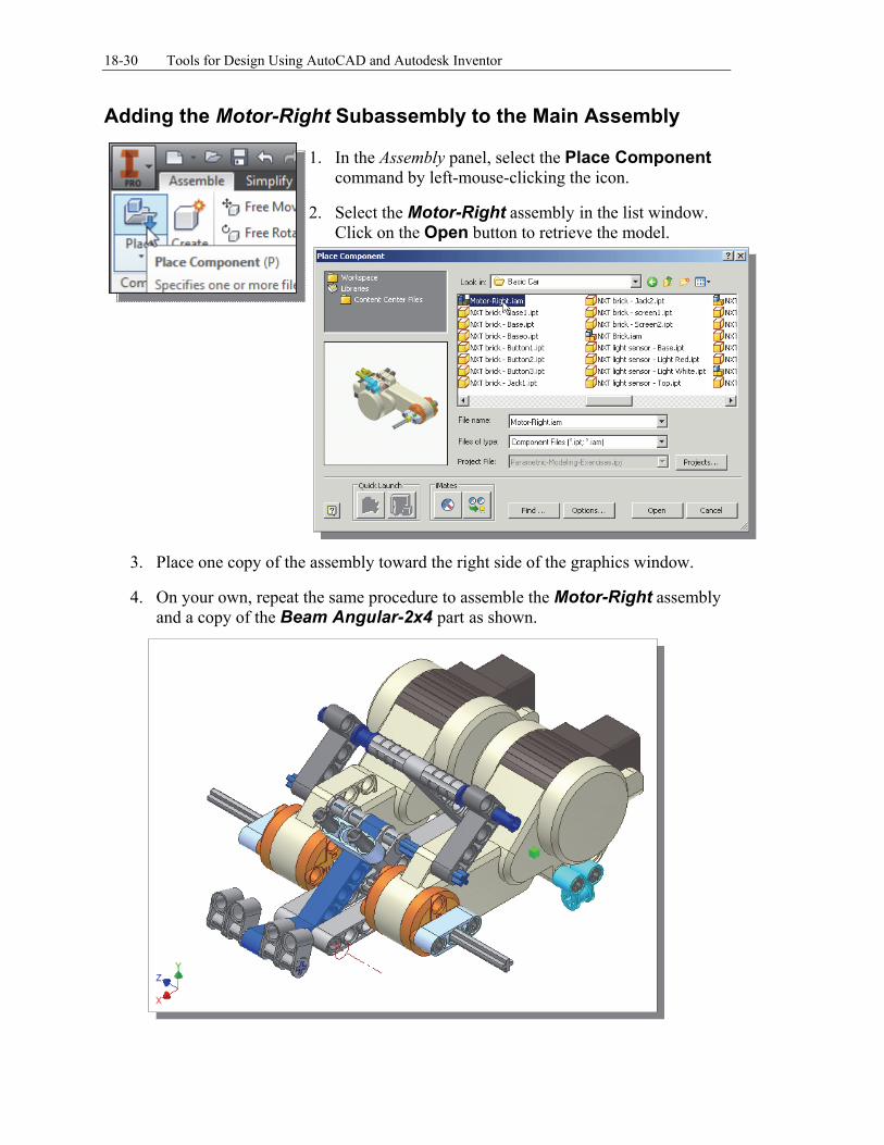
Adding the Motor-Right Subassembly to the Main Assembly 1. In the Assembly panel, select the Place Component
command by left-mouse-clicking the icon.
2. Select the Motor-Right assembly in the list window. Click on the Open button to retrieve the model.
3. Place one copy of the assembly toward the right side of the graphics window.
4. On your own, repeat the same procedure to assemble the Motor-Right assembly and a copy of the Beam Angular-2x4 part as shown.
Assembly Modeling with the LEGO® MINDSTORMS® NXT Set – Autodesk Inventor 18-31
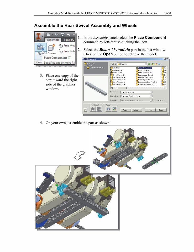
Assemble the Rear Swivel Assembly and Wheels
1. In the Assembly panel, select the Place Component
command by left-mouse-clicking the icon.
2. Select the Beam 11-module part in the list window. Click on the Open button to retrieve the model.
3. Place one copy of the part toward the right side of the graphics window.
4. On your own, assemble the part as shown.
18-32 Tools for Design Using AutoCAD and Autodesk Inventor
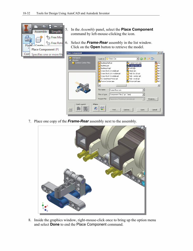
5. In the Assembly panel, select the Place Component
command by left-mouse-clicking the icon. 6. Select the Frame-Rear assembly in the list window.
Click on the Open button to retrieve the model.
7. Place one copy of the Frame-Rear assembly next to the assembly.
8. Inside the graphics window, right-mouse-click once to bring up the option menu
and select Done to end the Place Component command.
Assembly Modeling with the LEGO® MINDSTORMS® NXT Set – Autodesk Inventor 18-33
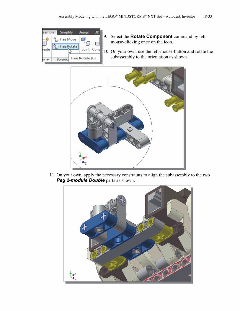
9. Select the Rotate Component command by left-
mouse-clicking once on the icon.
10. On your own, use the left-mouse-button and rotate the subassembly to the orientation as shown.
11. On your own, apply the necessary constraints to align the subassembly to the two Peg 2-module Double parts as shown.
18-34 Tools for Design Using AutoCAD and Autodesk Inventor
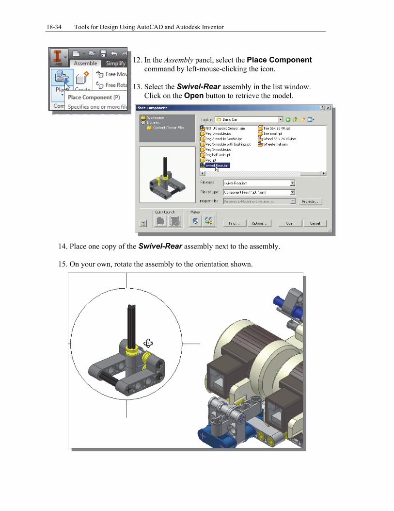
12. In the Assembly panel, select the Place Component
command by left-mouse-clicking the icon. 13. Select the Swivel-Rear assembly in the list window.
Click on the Open button to retrieve the model.
14. Place one copy of the Swivel-Rear assembly next to the assembly.
15. On your own, rotate the assembly to the orientation shown.
Assembly Modeling with the LEGO® MINDSTORMS® NXT Set – Autodesk Inventor 18-35
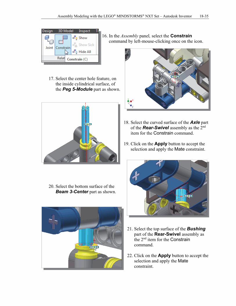
16. In the Assembly panel, select the Constrain
command by left-mouse-clicking once on the icon.
17. Select the center hole feature, on the inside cylindrical surface, of the Peg 5-Module part as shown.
18. Select the curved surface of the Axle part
of the Rear-Swivel assembly as the 2nd item for the Constrain command.
19. Click on the Apply button to accept the
selection and apply the Mate constraint.
20. Select the bottom surface of the Beam 3-Center part as shown.
21. Select the top surface of the Bushing
part of the Rear-Swivel assembly as the 2nd item for the Constrain command.
22. Click on the Apply button to accept the
selection and apply the Mate constraint.
18-36 Tools for Design Using AutoCAD and Autodesk Inventor
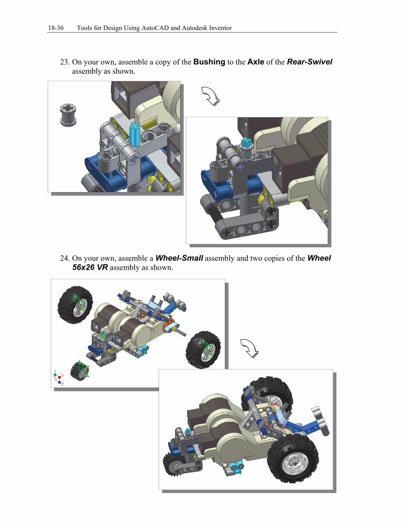
23. On your own, assemble a copy of the Bushing to the Axle of the Rear-Swivel
assembly as shown.
24. On your own, assemble a Wheel-Small assembly and two copies of the Wheel
56x26 VR assembly as shown.
Assembly Modeling with the LEGO® MINDSTORMS® NXT Set – Autodesk Inventor 18-37
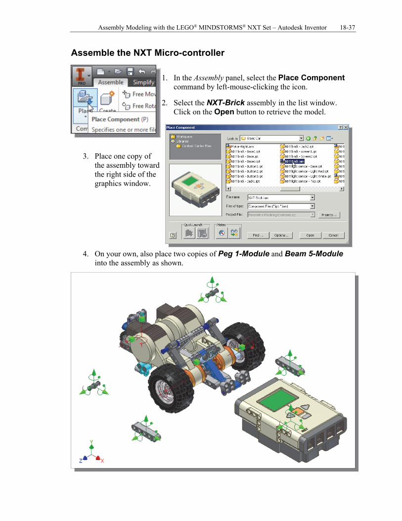
Assemble the NXT Micro-controller
1. In the Assembly panel, select the Place Component
command by left-mouse-clicking the icon.
2. Select the NXT-Brick assembly in the list window. Click on the Open button to retrieve the model.
3. Place one copy of the assembly toward the right side of the graphics window.
4. On your own, also place two copies of Peg 1-Module and Beam 5-Module into the assembly as shown.
18-38 Tools for Design Using AutoCAD and Autodesk Inventor
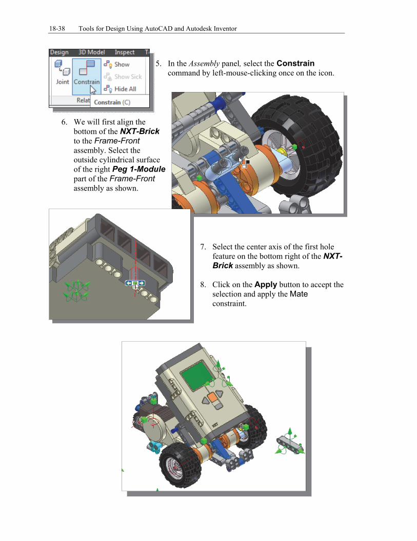
5. In the Assembly panel, select the Constrain
command by left-mouse-clicking once on the icon.
6. We will first align the
bottom of the NXT-Brick to the Frame-Front assembly. Select the outside cylindrical surface of the right Peg 1-Module part of the Frame-Front assembly as shown.
7. Select the center axis of the first hole
feature on the bottom right of the NXT-Brick assembly as shown.
8. Click on the Apply button to accept the
selection and apply the Mate constraint.
Assembly Modeling with the LEGO® MINDSTORMS® NXT Set – Autodesk Inventor 18-39
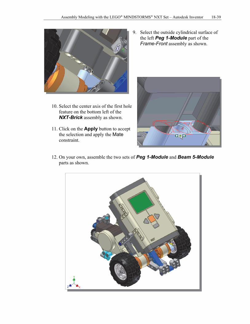
9. Select the outside cylindrical surface of the left Peg 1-Module part of the Frame-Front assembly as shown.
10. Select the center axis of the first hole feature on the bottom left of the NXT-Brick assembly as shown.
11. Click on the Apply button to accept
the selection and apply the Mate constraint.
12. On your own, assemble the two sets of Peg 1-Module and Beam 5-Module parts as shown.
18-40 Tools for Design Using AutoCAD and Autodesk Inventor
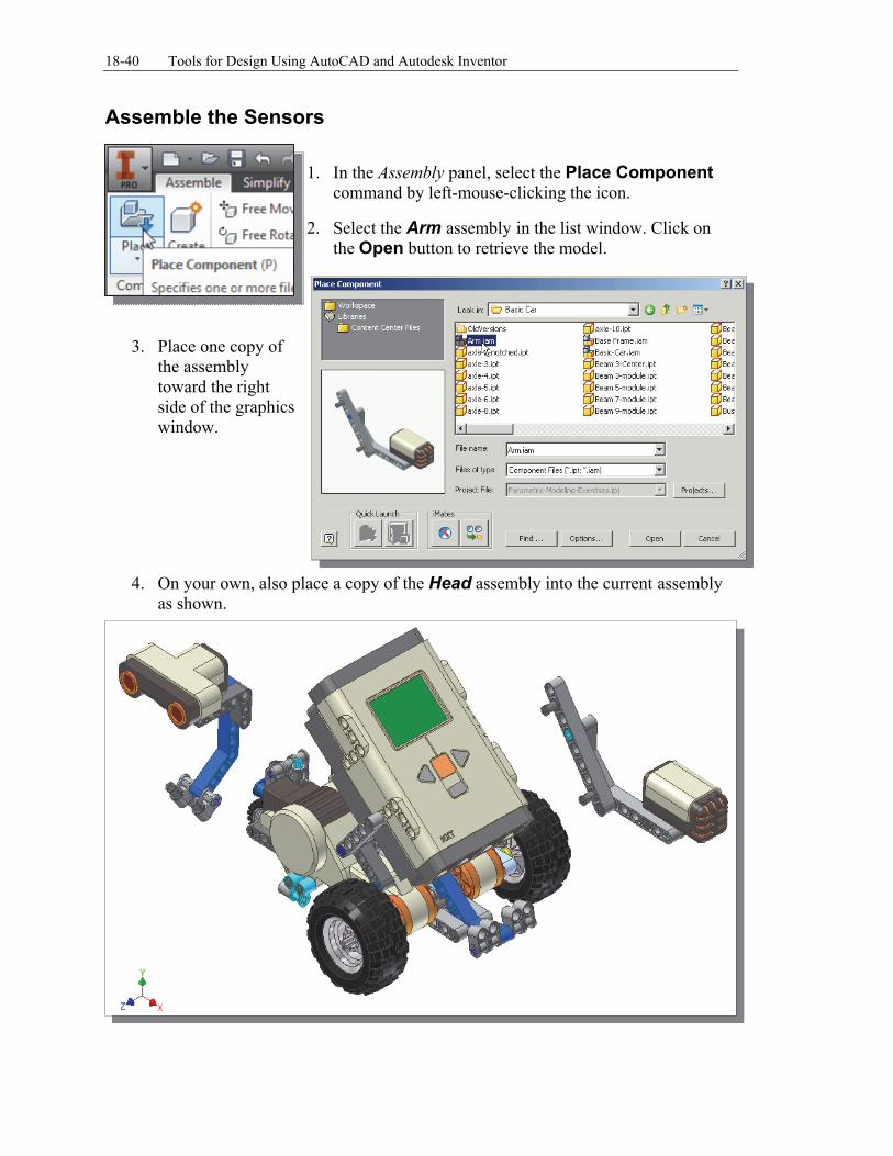
Assemble the Sensors
1. In the Assembly panel, select the Place Component
command by left-mouse-clicking the icon.
2. Select the Arm assembly in the list window. Click on the Open button to retrieve the model.
3. Place one copy of the assembly toward the right side of the graphics window.
4. On your own, also place a copy of the Head assembly into the current assembly as shown.
Assembly Modeling with the LEGO® MINDSTORMS® NXT Set – Autodesk Inventor 18-41
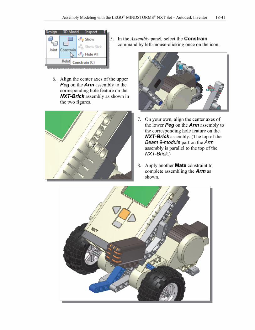
5. In the Assembly panel, select the Constrain
command by left-mouse-clicking once on the icon.
6. Align the center axes of the upper
Peg on the Arm assembly to the corresponding hole feature on the NXT-Brick assembly as shown in the two figures.
7. On your own, align the center axes of
the lower Peg on the Arm assembly to the corresponding hole feature on the NXT-Brick assembly. (The top of the Beam 9-module part on the Arm assembly is parallel to the top of the NXT-Brick.)
8. Apply another Mate constraint to
complete assembling the Arm as shown.
18-42 Tools for Design Using AutoCAD and Autodesk Inventor
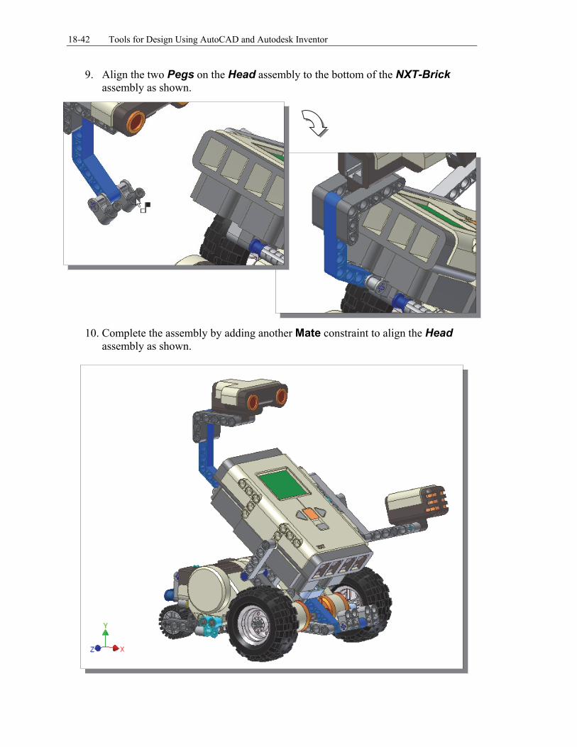
9. Align the two Pegs on the Head assembly to the bottom of the NXT-Brick assembly as shown.
10. Complete the assembly by adding another Mate constraint to align the Head
assembly as shown.