toolbox for 3d planning and risk assessment of ammunition ... · 34th dod explosives safety seminar...
TRANSCRIPT
34th DoD Explosives Safety Seminar 2010, Portland, Oregon
1
Toolbox for 3D Planning and Risk Assessment of Ammunition Field Depots F.K.F. Radtke, I. Stacke, M. Voss, C. Rizzuti, I. Häring
Fraunhofer-Institute for High-Speed Dynamics – Ernst-Mach-Institute,
Am Klingelberg 1, 79588 Efringen-Kirchen, Germany
[email protected], [email protected]
Keywords:
planning of ammunition field storage, risk assessment of field camps,
explosive ordnance disposal, EOD, risk management, hazard analysis,
damage analysis, explosive safety, industrial foundation classes, IFC,
forward operating base, rocket, artillery mortar (RAM) threat
Abstract A growing number of international missions of the German armed forces leads to an
increasing need for ammunition storage in field depots. Therefore improved planning
and risk assessment tools are needed. Type and intensity of an international mission
determine the number of deployed troops and the terrain available for field camps. This
defines also type and amount of required ammunition as well as storage conditions.
From limitations of space and available personnel the need of optimized planning arises,
including the comparison of different solutions for field depots. During the deployment
changes of the mission may occur. The presented 3D planning tool for ammunition field
depots allows easy and fast adaptation of the existing storage layout to changed
situations. The tool is based on military regulations. It makes intense use of databases,
computational geometry and relational algebra. Some risks caused by the stored
ammunition and given limitations cannot be avoided. We show how the German
explosive safety quantitative risk analysis software (ESQRA-GE) is applied to
representative planning scenarios. The ESQRA-GE follows an established risk assessment
methodology. Based on the modelling of physical hazards and damage, individual and
collective risks are computed. Past experience has shown that, in addition to interior
threats caused by stored ammunition, shelling poses a major threat. The level of passive
protection against rockets provided by representative structures of the field depot for
the ammunition is evaluated employing the code “risk analysis software for forward
operating bases – rocket, artillery, mortar (RAFOB-RAM)”. The presented 3D tools allow
the planning of ammunition field depots following the current technical guidelines of
the NATO and the German Armed Forces. They provide functionalities to assess the risk
due to stored ammunition and threats resulting from rocket shelling.

Report Documentation Page Form ApprovedOMB No. 0704-0188
Public reporting burden for the collection of information is estimated to average 1 hour per response, including the time for reviewing instructions, searching existing data sources, gathering andmaintaining the data needed, and completing and reviewing the collection of information. Send comments regarding this burden estimate or any other aspect of this collection of information,including suggestions for reducing this burden, to Washington Headquarters Services, Directorate for Information Operations and Reports, 1215 Jefferson Davis Highway, Suite 1204, ArlingtonVA 22202-4302. Respondents should be aware that notwithstanding any other provision of law, no person shall be subject to a penalty for failing to comply with a collection of information if itdoes not display a currently valid OMB control number.
1. REPORT DATE JUL 2010
2. REPORT TYPE N/A
3. DATES COVERED -
4. TITLE AND SUBTITLE Toolbox for 3D Planning and Risk Assessment of Ammunition Field Depots
5a. CONTRACT NUMBER
5b. GRANT NUMBER
5c. PROGRAM ELEMENT NUMBER
6. AUTHOR(S) 5d. PROJECT NUMBER
5e. TASK NUMBER
5f. WORK UNIT NUMBER
7. PERFORMING ORGANIZATION NAME(S) AND ADDRESS(ES) Fraunhofer-Institute for High-Speed Dynamics Ernst-Mach-Institute,Am Klingelberg 1, 79588 Efringen-Kirchen, Germany
8. PERFORMING ORGANIZATIONREPORT NUMBER
9. SPONSORING/MONITORING AGENCY NAME(S) AND ADDRESS(ES) 10. SPONSOR/MONITOR’S ACRONYM(S)
11. SPONSOR/MONITOR’S REPORT NUMBER(S)
12. DISTRIBUTION/AVAILABILITY STATEMENT Approved for public release, distribution unlimited
13. SUPPLEMENTARY NOTES See also ADM002313. Department of Defense Explosives Safety Board Seminar (34th) held in Portland,Oregon on 13-15 July 2010, The original document contains color images.
14. ABSTRACT A growing number of international missions of the German armed forces leads to an increasing need forammunition storage in field depots. Therefore improved planning and risk assessment tools are needed.Type and intensity of an international mission determine the number of deployed troops and the terrainavailable for field camps. This defines also type and amount of required ammunition as well as storageconditions. From limitations of space and available personnel the need of optimized planning arises,including the comparison of different solutions for field depots. During the deployment changes of themission may occur. The presented 3D planning tool for ammunition field depots allows easy and fastadaptation of the existing storage layout to changed situations. The tool is based on military regulations. Itmakes intense use of databases, computational geometry and relational algebra. Some risks caused by thestored ammunition and given limitations cannot be avoided. We show how the German explosive safetyquantitative risk analysis software (ESQRA-GE) is applied to representative planning scenarios. TheESQRA-GE follows an established risk assessment methodology. Based on the modelling of physicalhazards and damage, individual and collective risks are computed. Past experience has shown that, inaddition to interior threats caused by stored ammunition, shelling poses a major threat. The level ofpassive protection against rockets provided by representative structures of the field depot for theammunition is evaluated employing the code risk analysis software for forward operating bases rocket,artillery, mortar (RAFOB-RAM). The presented 3D tools allow the planning of ammunition field depotsfollowing the current technical guidelines of the NATO and the German Armed Forces. They providefunctionalities to assess the risk due to stored ammunition and threats resulting from rocket shelling.
15. SUBJECT TERMS

16. SECURITY CLASSIFICATION OF: 17. LIMITATION OF ABSTRACT
SAR
18. NUMBEROF PAGES
34
19a. NAME OFRESPONSIBLE PERSON
a. REPORT unclassified
b. ABSTRACT unclassified
c. THIS PAGE unclassified
Standard Form 298 (Rev. 8-98) Prescribed by ANSI Std Z39-18

34th DoD Explosives Safety Seminar 2010, Portland, Oregon
2
Brief presenter biography Frank Radtke started his working career as a research associate at TU Delft after
finishing his studies of civil engineering at the University of Hannover with a Dipl.-Ing..
Since 2009 he has been working at the Fraunhofer-Institute for High-Speed-Dynamics,
Ernst-Mach-Institute in the hazard and risk analysis group. His work was mainly focused
on ammunition storage safety and counter terrorism.
1 Introduction In this concept paper we present an integrated approach for planning and assessment
of field camps with a main focus on ammunition storage safety and passive structural
protection against RAM-threats (overhead and side protection).
Since a couple of years NATO nations face an increasing number of deployed missions.
Compared to the cold war era the type of conflict has changed. Instead of one
symmetric high intensity conflict a number of smaller asymmetric conflicts with
changing intensities occurs. This means that at the beginning of a mission the intensity
might be low and thus only a small number of light-armed forces is needed. But when
the intensity grows the capabilities have to be adapted which means that more forces
with different equipment are sent to theatre. But this also means that a field camp that
has been planned for e.g. light infantry might need to accommodate armoured troops
as well as artillery. Regarding ammunition storage different amounts and types of
ammunition need to be taken into account.
Resources for planning, construction, protection and operation of field camps and field
depots are always scarce. To increase complexity a field camp might be operated by
different nations potentially having different regulations regarding e.g. safety issues.
Naturally, the main thread originates from a possibly hostile environment. This might be
for example rocket, artillery or mortar shelling (RAM-threat). Also in this case, the
scenario is constantly changing.
To respond to this situation we are developing a toolbox of different interconnected
software tools to support planning and operating field camps with the focus on
ammunition field depots and protective structures against RAM-threats.
The first step is the partially automated site planning of ammunition field depots
following standard guidelines. If it is not possible to comply with appropriate
regulations, a more detailed analysis of the field depot is performed using a risk model.
Regarding exterior threats a model is employed describing the risk due to rocket, artillery
and mortar (RAM) shelling.
34th DoD Explosives Safety Seminar 2010, Portland, Oregon
3
2 Automated Site Planning of Ammunition Field Storage
2.1 Objective The automated site planning tool is supposed to be mainly used during the planning of
an ammunition field depot. But it should also support changes becoming necessary
during the use of the facility.
The user should be able to specify local boundary conditions as e.g. geographical
conditions and choose from standard configurations which can be adapted to special
needs.
As a result the user gets fully usable site plans including the needed resources as for
example number and type of ISO containers, geometry and material data, or the
amount of concrete for storage buildings.
In addition, it should be possible to enter the military forces and automatically compute
their required ammunition.
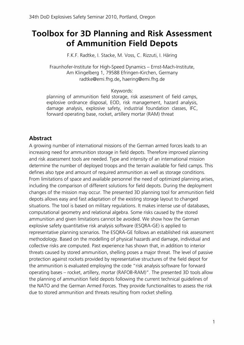
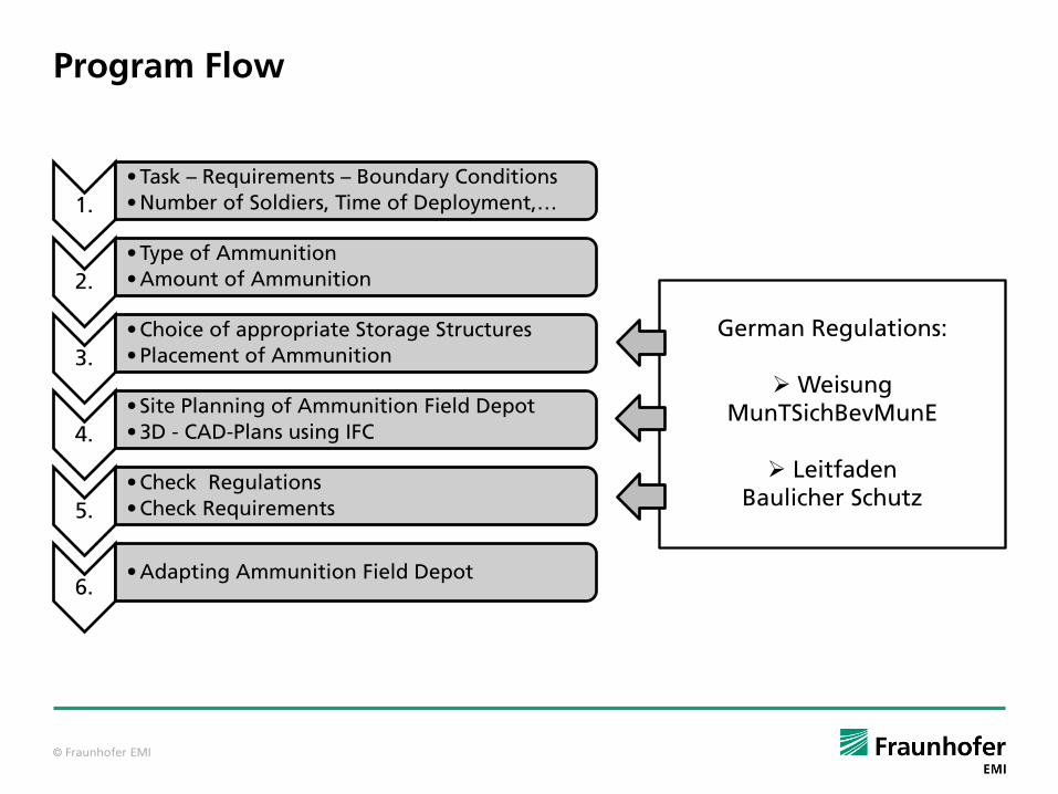
2.2 Approach In a first step the deployed military forces are specified which includes the specification
of the intensity of the conflict, the number of soldiers and the duration of the
deployment. Based on this information and based on regulations and experience of the
German Armed Forces the program calculates the required amount and type of
ammunition (as an example of the program output refer to Figure 1).
Figure 1: Example of the output of required ammunition generated by the ammunition field depot planning tool.
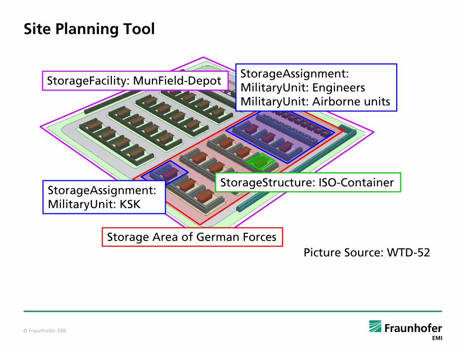
Based on this information, including the organizational structure of the deployed forces
and taking into account the appropriate regulations as e.g. [1, 2] a field depot is
generated as qualitatively depicted in Figure 2. Constraints due to the geometry of the
storage structure and the packaging of the ammunition are considered as well as typical
numbers of ammunition stored within a package.
The software automatically checks if the layout of the field depot complies with the
regulations, e.g. safety distances (QDs). In addition, it ensures that the appropriate type

34th DoD Explosives Safety Seminar 2010, Portland, Oregon
4
of storage structure is used for the stored ammunition. If this is not possible within the
given boundary conditions, hazard, damage and risk analysis can be conducted.
Figure 2: Example of an ammunition field depot; each military unit gets a storage assignment within the storage area of the national forces e.g. the German forces; each storage assignment
may consist of different types of storage structures.
3 Risk Assessment of Internal Threads due to Ammunition Storage If it is not possible to follow the regulations when planning an ammunition field depot,
it might become necessary to perform a hazard, damage and risk analysis. Based on this
analysis the depot might be optimized to reach an acceptable level of safety.
3.1 Objective The German explosive safety quantitative risk analysis model (ESQRA-GE) is intended for
the assessment of non-standard situations in ammunition storage, where existing
guidelines cannot be applied.
3.2 Approach In Figure 3 the risk management scheme for explosive events employed at EMI is
depicted. The first step is the scenario definition. In the presented integrated approach
the scenario definition is performed using the ammunition depot planning tool output
as described in Section 2. In the future we will directly import this data into the risk
analyses software ESQRA-GE.
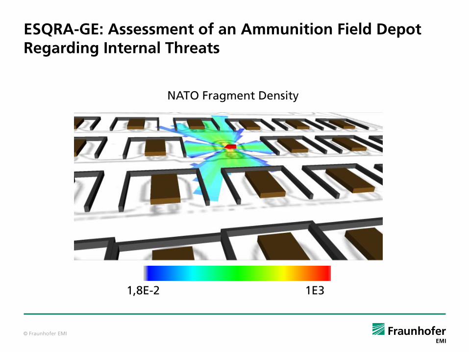
For a defined scenario the physical hazards as fragment throw or blast can be calculated
as shown in Figure 4.

34th DoD Explosives Safety Seminar 2010, Portland, Oregon
5
Based on the physical hazards, consequences, e.g. damage of buildings or the number
of injured persons, can be computed.
Including the fractional exposure of persons to hazards, and the frequency of an event
e.g. an unwanted explosion, the individual risk of persons can be evaluated. In this way
a scenario can be adapted such that safety is guaranteed to an acceptable level even if it
is not possible to comply with standard guidelines.
Figure 3: Risk management methodology employed at Fraunhofer Ernst-Mach-Institute (EMI).
The ESQRA-GE is described in more detail in [3–5].

34th DoD Explosives Safety Seminar 2010, Portland, Oregon
6
Figure 4: Density of all fragments (left) and density of fragments fulfilling the NATO criterion (right); fragment shadows due to barriers around the storage containers are clearly visible.
4 Risk Assessment of External Threads due to Shelling So far, we have considered hazards originating from inside a field camp as possible
threats. But naturally we also have to take into account a possibly hostile environment.
Current missions have shown that a major threat consists of the shelling of field camps
with rockets, artillery and mortar shells. Therefore, we develop a risk analysis (RA) tool
for forward operating bases (FOB) analyzing the effect of passive protection against
RAM. The tool RAFOB-RAM is supposed to use the output of the ammunition depot
planning tool as scenario input for a part of the analysed field camp.
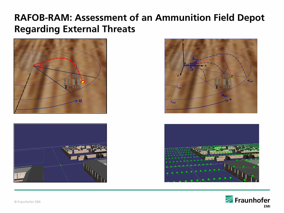
4.1 Objective The aim of the risk analysis model for forward operating bases (RAFOB-RAM) is to assess
different types of risk for personnel due to rockets, artillery or mortar shells fired into a
field camp as depicted in Figure 5.
Mitigation effects due to passive protection are taken into account. The aim is to detect
weak points of the passive protective measures – in particular in the ammunition storage
facilities.
For instance, for certain ammunition classes – high energy fragments cause initiation of
ammunition. Thus, ammunition storage sites might become hazards sources. Even more,
if sympathetic detonation must be considered.

34th DoD Explosives Safety Seminar 2010, Portland, Oregon
7
Figure 5: Example scenario with depiction of the outdoor exposure volume elements possibly containing persons.
4.2 Approach First, possible trajectories of RAM ammunition are calculated leading to a number of
representative impact trajectories in the camp as shown in Figure 6.
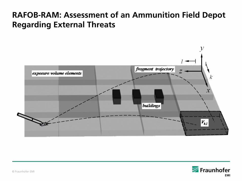
We consider different types of fuses and impact scenarios. Depending on the fuse type
we calculate for each representative impact trajectory the effects of representative
initiations in air, at impact or after perforation of structures. The fragment trajectories
are calculated. If the shell hits a building, penetration or perforation of the building are
computed. This generates threats inside a building due to primary fragments and
secondary debris from the building itself.
Knowing the fragment trajectories and specifying areas where people are located
possible injuries with different levels of severity can be calculated. To asses injuries for
persons we use a three dimensional representation of a human being taking into
account individual protection levels and positions (voxel model) [6].
Finally, using event frequency and fractional exposure of persons to different threats,
local and global individual and collective risks can be computed.
This information can be applied to identify critical components of the building structures
and to minimize resulting risks by employing structural hardening or protective
measures, e.g. barriers.
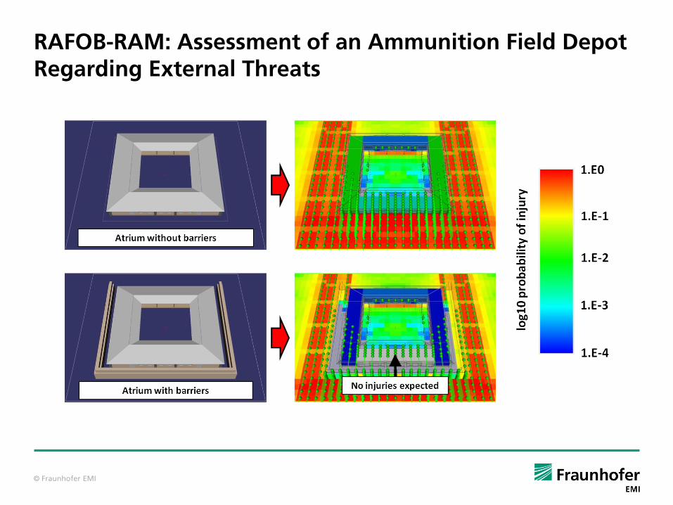
Figure 6 shows two calculated scenarios, where 625 representative initiation points were
calculated for the warhead of an unguided 107 mm rocket fired from 4 km away. The
upper part of the figure shows an atrium building with massive outer walls and a thick
concrete roof. In the lower part the same building is protected on three sides with 2 m
high walls. The protective barriers lead to a significant reduction of the injury probability
inside the building, as illustrated in the picture. Apparently the applied protective
measure is appropriate for a more effective passive protection. All possible single events

34th DoD Explosives Safety Seminar 2010, Portland, Oregon
8
for a rocket with an impact fuse were considered, i.e. the consideration of more
representative impact trajectories leads to the same results close to the building.
Figure 6: Minimization of consequences inside an atrium building with protective barriers.
5 Industry Foundation Classes as Interface Between Different Models
For users it is of highest importance to connect the different models in an efficient way.
Thus an interface for stable data exchange has to be defined. For this purpose we have
decided to use the Industry Foundation Classes (IFC) as data exchange format defined in
an ISO standard [7]. This ISO-standard is currently introduced to a number of CAD tools.
It has the advantage of storing all necessary data including geometrical data and
material data in an efficient hierarchical layer like structure as shown in Figure 7. An
example might be an ammunition storage house, where in addition to geometrical data
material data such as Young’s modulus or fracture energy can be assigned to the
different objects in the file-format. This will enable us, for example, to compute within
models like ESQRA-GE (refer to Section 3) and RAFOB-RAM (refer to Section 4)
penetration or perforation of barriers and walls by fragments in an efficient way. At the
same time the format contains all the information needed in the planning tool (refer to
Section 2) to generate site plans and resource lists.
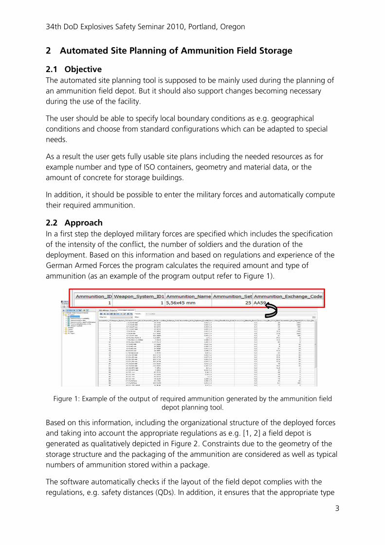
An important aspect regarding usability of the presented tools is the realistic
visualization (refer to Figure 8) of scenarios, and analysis of results using the IFC format.

34th DoD Explosives Safety Seminar 2010, Portland, Oregon
9
Figure 7: Layer structure of the industrial foundation classes (IFC) [8].
34th DoD Explosives Safety Seminar 2010, Portland, Oregon
10
Figure 8: Visualization of a typical building; screenshot taken from IFC Viewer,
Forschungszentrum Karlsruhe [9].
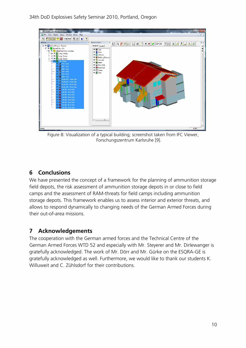
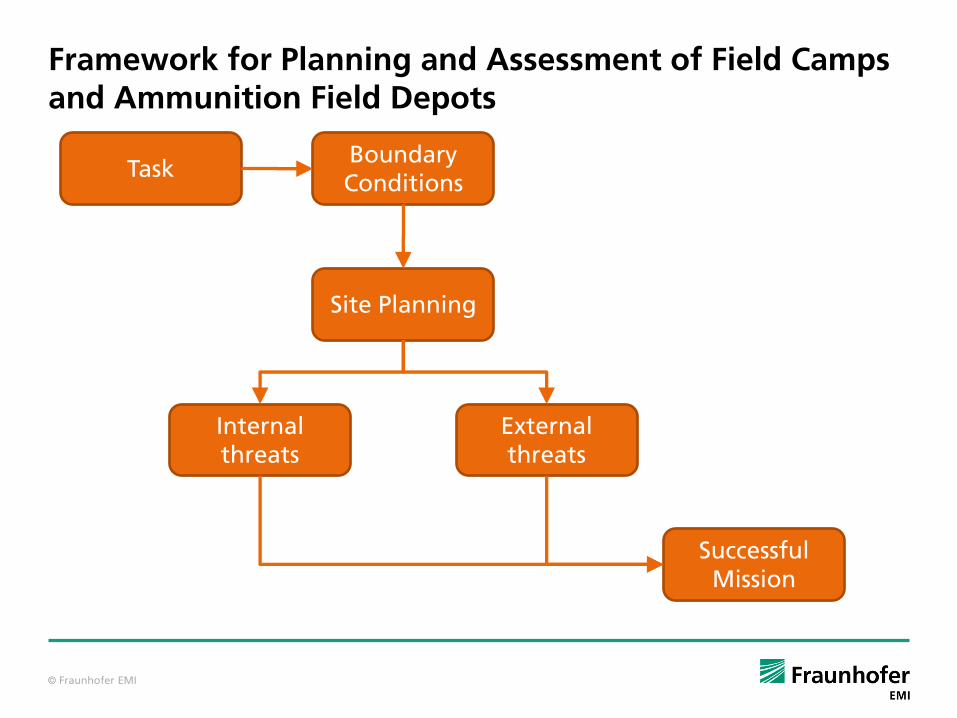
6 Conclusions We have presented the concept of a framework for the planning of ammunition storage
field depots, the risk assessment of ammunition storage depots in or close to field
camps and the assessment of RAM-threats for field camps including ammunition
storage depots. This framework enables us to assess interior and exterior threats, and
allows to respond dynamically to changing needs of the German Armed Forces during
their out-of-area missions.
7 Acknowledgements The cooperation with the German armed forces and the Technical Centre of the
German Armed Forces WTD 52 and especially with Mr. Steyerer and Mr. Dirlewanger is
gratefully acknowledged. The work of Mr. Dörr and Mr. Gürke on the ESQRA-GE is
gratefully acknowledged as well. Furthermore, we would like to thank our students K.
Willuweit and C. Zühlsdorf for their contributions.

34th DoD Explosives Safety Seminar 2010, Portland, Oregon
11
References 1. Wehrtechnische Dienststelle 52: Leitfaden Baulicher Schutz bei Bevorratung von
Munition im Einsatz (2007)
2. Streitkräfteunterstützungskommando: Weisung Munitionstechnische Sicherheit bei
der Bevorratung von Munition im Einsatz (MunTSichhBevMunE) (2008)
3. Doerr, A., Guerke, G., Ruebarsch, D.: The German risk-based explosive safety code.
In: 30th DoD Explosives Seminar (2002)
4. Doerr, A., Gürke, G., Ruebarsch, D.: The German explosive safety code ESQRA-GE.
In: US DoD (ed.) 32nd Dod Explosive Saftey Seminar 2006 (2006)
5. Dörr, A., Voss, M., Gürke, G.: Technisches Handbuch ESQRA-GE Version 2.0 (2007)
6. Voss, M., Dörr, A., Rizzuti, C., Häring, I.: Risk analysis for forward operating bases,
rocket, artillery, Mortar (RAFOB-RAM), Abschlussbericht 2009 (2010)
7. International Organization for Standardization (ISO): Inustry Foundation Classes,
Release 2x, Specification (IFC2x Platform) (2005)
8. Liebiech, T., Jeffrey, W.: IFC Technical Guide. Industry Foundation Classes - Release
2x
9. IfcViewer, Karlsruhe Institute of Technology, Institut für Angewandte Informatik

© Fraunhofer EMI
TOOLBOX FOR 3D PLANNING AND RISK ASSESSMENT OF AMMUNITION FIELD DEPOTS
F.K.F. Radtke, I. Stacke, M. Voss, C. Rizzuti, I. Häring
Corresponding author: Radtke, [email protected]äring, [email protected]

© Fraunhofer EMI
Outline
• Introduction
• Site planning tool
• Risk assessment for ammunition field depots and field camps regarding internal threats
• Risk assessment for ammunition field depots and field camps regarding external threats
• Interface between the different tools
• Conclusions
© Fraunhofer EMI
Framework for Planning and Assessment of Field Camps and Ammunition Field Depots
Site Planning
Internal threats
External threats
TaskBoundary Conditions
Successful Mission
© Fraunhofer EMI
Site Planning Tool
Storage Area of German Forces
StorageAssignment: MilitaryUnit: EngineersMilitaryUnit: Airborne units
StorageAssignment: MilitaryUnit: KSK
StorageStructure: ISO-Container
StorageFacility: MunField-Depot
Picture Source: WTD-52
© Fraunhofer EMI
Program Flow
1.
• Task – Requirements – Boundary Conditions
• Number of Soldiers, Time of Deployment,…
2.
• Type of Ammunition
• Amount of Ammunition
3.
• Choice of appropriate Storage Structures
• Placement of Ammunition
4.
• Site Planning of Ammunition Field Depot
• 3D - CAD-Plans using IFC
5.
• Check Regulations
• Check Requirements
6.• Adapting Ammunition Field Depot
German Regulations:
WeisungMunTSichBevMunE
LeitfadenBaulicher Schutz

© Fraunhofer EMI
Weapon System
Type of Ammunition
Compatibility Groups
Storage Structures Max NEQ per Storage Structure
QDs
Data Structure of the Site Planning Tool
© Fraunhofer EMI
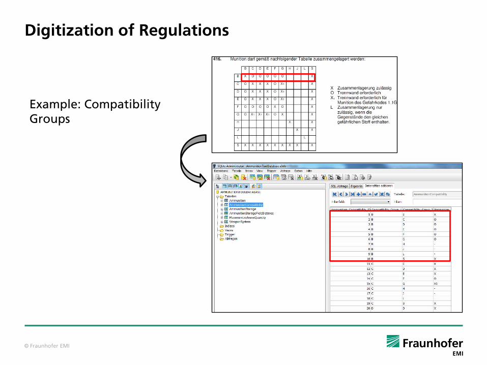
Digitization of Regulations
Example: CompatibilityGroups

© Fraunhofer EMI
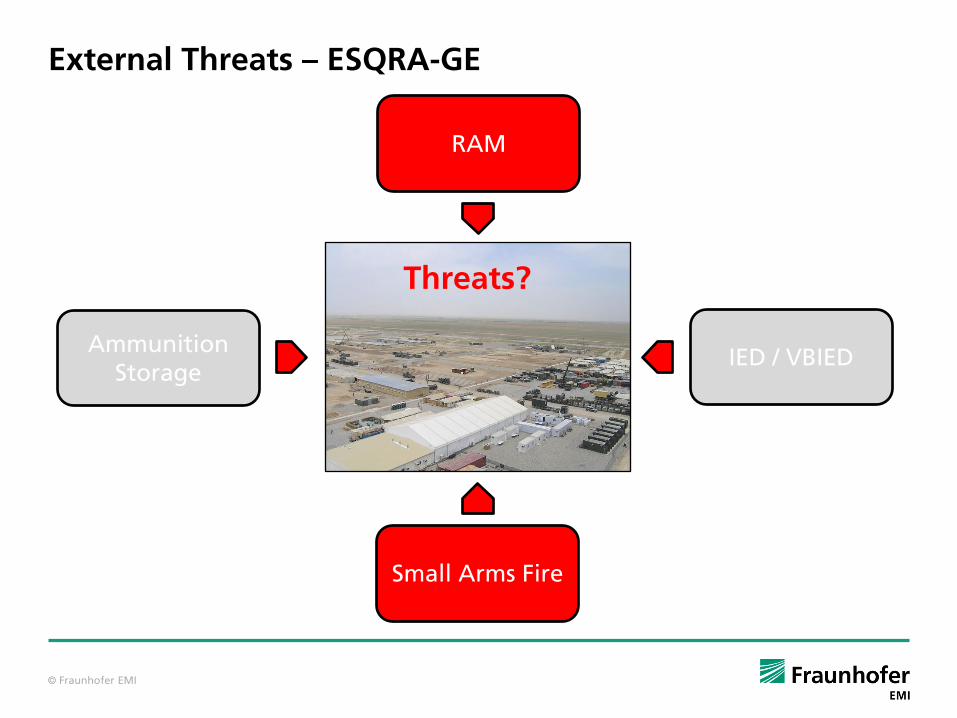
Internal and External Threats
RAM
IED / VBIEDAmmunition
Storage
Small Arms Fire
Threats?

© Fraunhofer EMI
Risk assessment for Ammunition Field Depots
Threat scenario
Physical hazards
Damage / Consequences
Exposure
Event frequency
Risk per year, per event, individual, group
Reference risk
Protection measures
Accept or change scenario
Hazard and damage analysis
Probability analysis
Risk communication
Risk minimization
Risk analysis
Risk management

© Fraunhofer EMI
Internal Threats – ESQRA-GE
RAM
IED / VBIEDAmmunition
Storage
Small Arms Fire
Threats?

© Fraunhofer EMI
ESQRA-GE: Assessment of an Ammunition Field Depot Regarding Internal Threats
Ammunition Field DepotPES
ISO ContainerBarrier

© Fraunhofer EMI
ESQRA-GE: Assessment of an Ammunition Field Depot Regarding Internal Threats
All Fragment Density
8,6E-7 1E3
© Fraunhofer EMI
ESQRA-GE: Assessment of an Ammunition Field Depot Regarding Internal Threats
NATO Fragment Density
1,8E-2 1E3

© Fraunhofer EMI
ESQRA-GE: Assessment of an Ammunition Field Depot Regarding Internal Threats
Damage Zone for Vehicles: Zone C – slight or no damage
© Fraunhofer EMI
External Threats – ESQRA-GE
RAM
IED / VBIEDAmmunition
Storage
Small Arms Fire
Threats?
© Fraunhofer EMI
RAFOB-RAM: Assessment of an Ammunition Field Depot Regarding External Threats
x
y
z
max
min
rmin
rmax
min
max

© Fraunhofer EMI
RAFOB-RAM: Assessment of an Ammunition Field Depot Regarding External Threats
© Fraunhofer EMI
RAFOB-RAM: Assessment of an Ammunition Field Depot Regarding External Threats
© Fraunhofer EMI
RAFOB-RAM: Assessment of an Ammunition Field Depot Regarding External Threats

© Fraunhofer EMI
IFC – Format: Interface Between the Different Tools
Quelle: www.koramic.de
Quelle: Google SketchUp
3D CAD-Data, Material Data, Strength of Material, Amount of Reinforcement, Use
3D Vizualisation using IFC

© Fraunhofer EMI
Structure of IFC Data Format
Resource Layer
Core Layer
Interoperability Layer
Domain LayerContains all information interesting for a specific task e.g. electric installations in a building
Contains all information where two or more domain layers intersect
Abstract definition of e.g. building elements like walls or foundations specified in domain or interoperability layer
Contains smallest entities, e.g. vertices, units
Abstract definition of the members of the extension scheme
Kernel
Extension Scheme

© Fraunhofer EMI
IFC – Format: Interface between the Different Tools
Screenshot taken from IFC Viewer, ForschungszentrumKarlsruhe

© Fraunhofer EMI
Conclusions
Site Planning
Tool
RAFOB-RAM
ESQRA-GE
IFCIFC
IFC