tool engineering by mcgraw hill
TRANSCRIPT


JIGS AND FIXTURES

TOOL ENGINEEKING
JIGS AND FIXTUEES
BY
ALBERT A. DOWDMember American Society of Mechanical Engineers; Author of "Tools,
Chucks and Fixtures," "Tools and Patterns," "Modern Gaging
Practice," "Fixtures for Turning, Boring and Grinding"
"Punches, Dies and Gages" etc.
AND
FRANK W. CURTISAssociate Member American Society of Mechanical Engineers; Western
Editor of American Machinist; Author of "Cutting Speeds and
Feeds,""Modern Gaging Practice
""Fixtures for Turning,
Boring and Grinding," "Punches, Dies and Gages," etc.
FIRST EDITIONSEVENTH IMPBESSION
McGRAW-HILL BOOK COMPANY, INC.
NEW YOKK AND LONDON1922

COPYRIGHT, 1922, BT THE
McGRAW-HiLL BOOK COMPANY, INC.
PRINTED IN THE UNITED STATES OF AMERICA
THE MAPLE PRESS COMPANY, YORK, PA.

DEDICATED TO THE
MANUFACTURERS OF THE UNITED STATES


PREFACE
The aim and purpose of this book is to furnish information
with respect to the science of tool engineering. Nothing has
previously been published on the subject except in short articles
dealing with specific examples of jigs and fixtures. Information
of value regarding principles of design in connection with produc-tion tools is sadly lacking and mechanical literature contains
only spasmodic efforts to remedy the deficiency.
In order to cover the subject properly three volumes were
planned, each of these being complete in itself. This volume,which is the first, deals with the design of jigs and fixtures, It
covers the important points connected with the design, shows the
reasons why certain methods are better than others, takes upprinciples and their application to design and gives many graphic
examples which illustrate the use of the principles involved. Anendeavor has been made to simplify the subject matter as far
as possible and to treat it in a practical common sense mannerwhich can be easily understood by the designer. A careful
study of the illustrations and descriptive matter will enable a
progressive man to understand both the theory and practice
necessary for this line of work.
The second volume takes up turret lathe and vertical boringmill tooling together with grinding fixtures. The third volume
deals with punches, dies and gages.
For a number of years the machines and tools used for pro-duction have been undergoing a process of evolution and althoughthe development work has progressed rapidly, much still remains
to be done. Present manufacturing methods are of the highestorder and tooling for high production is of interest to all the
mechanical fraternity. There are however, comparatively few
men in this country who really know the science in all its funda-
mentals and for this reason the tooling in many factories is
probably not over 50% efficient.
A great many of those responsible for tooling are not well
informed as to the fundamentals of design. Tools are workedout more or less by using ideas in vogue in the factory where the
work is being done and the design is usually influenced byprevious practice for work of the same character.
vii

viii PREFACE
Progressive tool engineering requires first of all, a thorough
knowledge of principles and the ability to specify the machining
operations necessary on a given piece of work. With this as a
basis, mechanical problems can be analyzed and the solution
obtained by the application of known principles. For this
reason our books take up the subject fundamentally and deal
largely with principles although many examples of interesting
fixtures are illustrated. Mechanical principles are fixed and do
not change from year to year as designs often do; hence, the manwhose knowledge of tools is firmly grounded on sound mechanical
principles is independent, original and progressive, so that his
designs are practical, economical and productive.
The superintendent, factory manager, foreman and tool
engineer will find theory and practice combined in such a waythat the principles on which the science is based will be readily
understood. The reasons why one design is better than another
are graphically shown in numerous examples, dealing with actual
cases observed during the writers' long experience in handling
production problems both in shop and drafting room. Problems
are analyzed; causes of trouble shown; correct and incorrect
methods illustrated; and much valuable data are given regarding
designs and proportions of jigs, fixtures, turret lathe tools,
punches, dies and gages.
M is our belief that the work will be appreciated by mechanical
men throughout the country. We hope that the many practical
examples will provide food for thought and eventually bring
about a general revision and radical improvement in tooling
methods.ALBERT A. DOWD.
NEW YOKK, FRANK W. CURTIS.December, 1922.

CONTENTSPAGE
PREFACE v
CHAPTER I
OUTLINE OP TOOTJ ENGINEERING 1-17Effect of Design on Manufacturing- Consideration of Limits
of Accuracy Selection of Working Points Tool OperationSheets Relation of Design to Cost of Machining.
CHAPTER II
FUNDAMENTAL POINTS IN DRILL JIG DESIGN 18-39Value of Analysis Location of Rough and Finished WorkCorrect and Incorrect Location and Clamping Clearance for
Work and ChipsProvision for Wear on Locating Surfaces
Setting Up and Removing Work Types of Jigs.
CHAPTER III
DETAILS OF DRIIA JIG CONSTRUCTION 40-81
Plain Clamps Multiple ClampsHook-Bolt and WedgeClamps Equalizing Clamps Spring Plungers and Jacks V-Block Design Leaf Jig Design Leaf Construction Clampsin the Leaf Leaf Stops Leaf Locks Standard Jigs and
Components Jig Bodies- Standardisation of Jig Posts and
ThumbscrewsJig Foefe Locating PlugsTypes of Bushings
Bushing Design and ProportionMethods of Holding
Slip Bushings Standard Knobs and Thumbscrews Ejectors.
CHAPTER IVOPEN AND CLOSKB JIGS 82-100
Templet Jigs--Plate Jigs Open Jigs for a Shaft Open Jig
for a Pump Cover Closed Jigs Closed Jigs for Angular and
Straight Holes- Locating and Assembling Jigs An Examplefor Practice.
CHAPTER V
INDEXING AND TBTONION JIGS 101-133
Indexing Requirements- Drilling and Reaming IndexingFixtures Four-Sided Jigs for Accurate Work Principles
and Methods of Indexing Index Plungers and Latches
Combined Index and Latch Specific Examples of Index-
ing Jigs Roll-Over Jigs Trunnion Jigs Double Trunnion
Jig A Difficult Drilling Problem Trunnion Jig Used
Progressively,

x CONTENTS
CHAPTER VIPAGE
DETAILS OF MILLING FIXTUKE CONSTRUCTION 134-181
Types of Milling Machines Types of Cutters ImportantDetails in Fixture Construction Elimination of Lost TimeElements Necessary in Efficient Tool Designing LocatingPoints Methods of Clamping Applications of the Lever
Multiple Clamps Design and Use of the Hook-Bolt Sup-
porting and Clamping Thin Castings Principles and Methodsof Pneumatic Clamping.
CHAPTER VII
DESIGN OP MILLING FIXTURES 182-212
Fixtures for Hand-Milling Form-Milling Attachments
Design and Operation of Indexing Fixtures Semi-Automatic
and Automatic Indexing Devices Uses of Twin Fixtures
Fixtures for Continuous Milling.
CHAPTER VIII
DESIGN OF PROFILING FIXTURES 213-229
Principles Involved Types of Profiling Machines CamMilling Irregular Forms Methods of Roughing and Finish-
ing Multiple Fixtures.
CHAPTER IX
VISE-JAWS AND VISE FIXTURES 230-246
Special and Swivel Jaws Devices for Insuring Accuracy
Quick Operation Devices for Equalizing Pressure Auto-
matic Ejectors.
CHAPTER X
BROACHES AND BROACHING FIXTURES 247-267
Principles of Design Tooth-Spacing and Chip-Clearance
Burnishing Keyway Broaching Multiple Fixtures Index
Broaching Spiral Broaching.
CHAPTER XI
DESIGN OF RIVETING FIXTURES 268-282
Riveting Machines Types of Rivets Locating and Clamp-ing Use of Tables Ring-Staking Tools and Fixtures
Ejectors.
INDEX 283

TOOL ENGINEERINGJIGS AND FIXTURES
CHAPTEE I
OUTLINE OF TOOL ENGINEERING
EFFECT OF DESIGN ON MANUFACTURE CONSIDERATION OF LIMITS
OF ACCURACY SELECTION OF WORKING POINTS TOOL OPERA-
TION SHEETS RELATION OF DESIGN TO COST OF MACHINING
The science of tool engineering as it is now practiced dates
back comparatively few years and very high production tooling
is of even more recent date, A few years ago when productionwas small the majority of jigs were made as cheaply as possible,
no great attention being paid to upkeep, because production wasnot sufficiently high to warrant it, except in the case of productswhich had been to some extent standardized, such as military
rifles, army pistols, sewing machines, and similar work. Theusual practice in the old days was to make a rough list of opera-tions which was to be followed and then give a few free-hand
sketches to the toolmaker to show him approximately how the
tools were to be made, leaving many of the details to the manhimself. "When this man needed a pattern he went to the pat-tern maker and told him what he wanted, leaving the propor-
tioning of the pattern to him. Then after the casting had been
made the toolmaker "whittled" it out until a makeshift jig was
evolved, which served its purpose in the production of so-called
interchangeable parts.
The tool engineer of the present day must be up to date in
the manufacturing field;must have a broad knowledge of ma-
chine tools;must understand the theory and practice of cutting
tools, speeds, feeds and kindred subjects and should have prac-tical shop training of such a nature that he knows from his ownexperience just how a given machine is handled and what the
1

2
requirements are for tools t l** usni HI* if, If ! *liu^ imt
this knowledge he will not ! .'ill- t ilu th- work r-,|iiii
him in the mast efficient wannrr,
Listing of Operations. In nj tn ,i,iv
first step in the process in tin* li
necessary to machine etith umtp
whieh is to be matmfnetttml ttt
step in the manufacture* is MMI
viewpoints, such an: Kconnnt> in
suitable; tooling equipment awnl
euraey required; ji>?s nl fixture i"
etc. In many cases, also ttirK m*i> >*j'i< 3.,, 'h.i'n,)'?^,
hardening, grinding nftt't fiiml* 11114*. M ; ^/ .1 *^i,>,/ i ,
other unit, poliKhiu^ bluing **r n ur IjM.it.u* 1 ' ^ * -
*
ters must be cotusidcrctl in tii*1
li*!ut', 'f M, MM *.? ||
it is evident that the tool t'n*,!wr' tufinf i>* ^ <, > I'.un
with the procesneK of machitnu'", liar) ?.,',* tM ^ ! ^M
ing, but he must also tm<t<*!st;in*i fl* *M|,I ? .j ( , ^.^ .,4
ism as a whole in oinltr that In* if- i !^ ^^
for machining thin or that MirtW i ilutt i1 % Jl l
relation to some other hull* r 41 MI^M J
unit will function pni|iert>%
Points To Be Considered I*H n * j utf> f-1 a 4 ^i** 145
of a certain part in tunttd *VIT t** llir !,) i t |MtM^ w^hstatement that the part ifriiivinr tins liin -j j^ M,| fl .,j r )t
for tooling. The following (ititnts niii t tt*n i ?,,^, j, imsideration in listing the cifii'iiitnnn,
1. Production K^mrnL TIiK i*^ m ii.i^^if i^l ^ jt*<l*'r t
whieh affects the methmi of t,, 4 ,,M ,|< ^.^ n
If a comparatively smiill iitimiirr M f jrr.v. ^ t,* . j^Hj^tured, the tools muM ht .snii|l* iunt *h. rtr m .., M *,,},tool cost as low an pttHhihh*. It n larfr im^ 1
^! ,'f . , -^be manufactured, mnltit!t< , ( ,,| ,-,uu j
'
M,M \^ j^
would be called for, in onli*r fn III*KJ ? |', n^ ,-: v/ ,, ,
jt|fas possible. In the latter t^iiw t|,,- ,., fi t -f *...!. v m^i iltributed over mieh a Rn*nf iiiimliir i,f ,,-,,, .^a* h. amffor took would not hi* I'xmNiv**,
a. Material of Winch th* M'.U /i H^l* ft Ir .t . f ir a r.
ing, a forging omtHrapin^ r if f ,u> ! fM4l j,. ffNfll , , ? fi|
stock. If a easting it may tim i fll , |M,yr4( . ^ ^.^ ,

OUTLINE OF TOOL ENGINEERING 3
snagged on a rough grinding wheel before machining. If it is
a thin or irregular easting it should first be inspected both for
quality and to wee whether it has warped out of shape KO that
it cannot be machined to proper dimensions. 11 a forging it
may require heat treatment before or during machining" or it
may be hardened and afterward ground so that necessary allow-
ances must be made during the machining to provide sufficient
stock for grinding. If made from round stock it may be found
best to machine it from the bar on a screw machine, or perhapsHM length and general shape may make handling it more profit-
LLLU
Fig. 1. Kxnmph* Khowhig tin* KMfahliHhmwtt* of Work lug Hurftuwti To HiIWd ! Locating th* Work During Mwltitihig
able on a manufacturing lathe after cutting it into lengths on
a cold saw or a eutting-off machine. It IB evident from the
foregoing that the material of which the part is made is an
important factor in the machining.
3. Surfaces To Be Marh-inecLln considering the various
holes to ho drilled, hored or reamed and the various surfaces
to he machined, it is important first to decide 1 whether the vari-
OUH holea can be drilled in one jig, or several jig will he re-
quired ; next, whether several milled surfaces can bo machined

JIGS AND FIXTURES
in one setting or it will be more economical to make several
operations. It is also necessary to decide whether any other
operations that may be necessary can be handled to best advan-
tage in combination, or by several operations. It is not good
practice to drill small holes and large ones in the same jig, unless
drilling machines can be so arranged as to obtain correct spindle
speeds for the different sizes of drills required. In special cases
it may be found profitable to do something of this kind in order
to avoid a resetting of the wark and the cost of an extra jig.
4. Accuracy Required. In any mechanism there are certain
fundamental principles affecting the successful operation of the
device. In order that it may function properly as a unit the
various components which make it up as a whole must fit each
other within certain limits of accuracy. These limits are usually
specified on the drawings of each part and the tool engineer must
keep them in mind when listing the operations as well as when
designing the limit gages used in the production of the parts.
The accuracy with which various machine tools will work must
be taken into consideration and if their accuracy is not suffi-
cient to produce the results required, a final fitting or grinding
operation may be necessary. So it is apparent that the accuracy
required is a factor of importance in listing operations.
5. Selection of Working Points. In order to obtain the best
results in production it is advisable to select working points
which can be used for location in all of the operations on the
work. It is difficult to give a hard and fast rule for determiningwhich points are the best to work from, due to the fact that dif-
ferent cases require different treatment and various pieces of
work are of such widely different design that no fixed rule can
be given to apply to all instances. A very good thought in con-
nection with the establishment of locating points is first to ob-
tain a flat surface and next machine two or more holes perpen-dicular thereto if the nature of the piece will permit it. In a
case of this kind it is possible to work from the finished surface
for all the subsequent operations, locating by means of pins in
the drilled or reamed holes, and in this manner making certain
that correct relations are kept for all the operations with the
points established as working points. Sometimes it may be neces-
sary to vary this procedure on account of the shape of the work,but the matter of establishing the working points must always

OUTLINE OF TOOL ENGINEERING 5
be considered very early in the listing of operations. A very
good example which shows the establishment of working points
is shown in Fig. 1, in which the flange A is first milled to give
a surface to work from and in the next operation the flange
holes B are drilled and two holes C reamed to give the other
locations so that the work can be carried through its various
operations by using these points from which to locate.
6. Provision for Chucking. In the handling of work on the
turret lathe it is frequently necessary to provide means for
clamping or holding the work during the first operation. There
are many cases where the shape of the work is such that it can
be held in a chuck without difficulty, but in other instances it-
may be found necessary to provide the work with lugs in order
to hold it properly. A case of this kind will be noted in the
hub, illustrated in Fig. 2. In this case it was decided to ma-
chine the surfaces marked / in the same setting, and obviously
it would be difficult to hold by means of the tapered portion A.
By the addition of three lugs B the work can be readily held bythe chuck jaws C, as indicated in the illustration. "When lugs
of this kind are added to a easting they may be removed by a
subsequent operation or they may be left as they are, provided
they do not interfere with the appearance or utility of the
finished product.
7. Concentricity of Cylindrical Surfaces. In the listing of
operations the importance of concentricity of the cylindrical sur-
faces which must be in alignment should be carefully considered,
as any variation from the truth will cause the mechanism when
completed to cramp and not run smoothly. It is advisable wher-
ever possible to machine concentric cylindrical surfaces in the
same setting, but as this is not always practical, particular at-
tention must be paid to the method of holding, when several
operations are used, in order that the work may be true when
completed. A very good example of a piece of work of this
character is shown in Fig. 3. In this case the bearing seats Aand B must be concentric to each other, and yet it is apparent
that the two surfaces cannot be machined in the same setting
of the work. For this reason the greatest care must be exer-
cised in designing the tool equipment so that the first bearing
seat B will be used as a location from which to produce the
second bearing seat A. Many other examples could be given of

6 JIGS AND FIXTURES
work of this character, but the instance given is a representative
one which will serve to illustrate the points involved.
8. Machines Required and Available. In the selection of ma-
chines for the work in process it is necessary that the tool engi-
neer should be familiar with the various types of machine tools
most suited to the work. In listing operations for an old plant
having a considerable assortment of machine tools from which
Chucking
'
jSection E-E
Fig. 2. Addition of Chucking Lugs to Assist in Machining
to choose the tool engineer must have a list of these machines
together with necessary data on their capacities and their work-
ing ranges. It must always be borne in mind, however, that the
selection of a machine for high production should not be* de-
pendent entirely upon the machine tools which are in stock, andit may be more profitable to purchase new equipment rather
than to use old equipment which is out of date and does not
give maximum efficiency.

OUTLINE OF TOOL ENGINEERING 7
Buy Tools as Needed. It is obvious that when listing opera-tions for a new plant the machine tools can be selected as theyare needed and can be -bought as the occasion demands. In cases
of this kind the tool engineer must be open-minded and mustmake his selection after having looked into the possibilities of
the- newer types of machines on the market.
Fig. 3. Concentricity Between Seats A and B Very Essential
Plant Layout. In. handling production work the layout of
the plant has an important bearing on the speed with which the
work can be routed through the factory. In the case of a new
factory it is evident that a plant layout must be made which will
show the position of all machine tools suitably placed, so that
there will be room for the piling up of raw material and the
finished product. The plant engineer who understands his busi-
ness takes all these matters into consideration.
Some of the points which come up in the placing of machines

8 JIGS AND FIXTURES
are illustrated in Fig. 4. In this case the drilling machines
shown at A and B and the tapping machine shown at C have
Drill Drill TapMachines Too Close
Fig. 4. Example Showing Drilling Machines Set Too Close Together
been placed so close together that it would be difficult to find
space for the work both before and after machining. A muchbetter arrangement is shown at Dy E and F in Fig. 5. It will
^Drill Drill
Proper Spacing
Tap
Fig. 5. Drilling Machines Properly Spaced
be noted that these machines are more widely separated so that
boxes can be placed between them for collecting the material
as fast as it has been drilled or tapped. These boxes can be so

OVTL1XK OF TOOL KNQINRKR1NQ
made that they will hang on the edge of the drill-proas table, or
they can be resting on the floor. They can be readily removed
and replaced if desired.
Another example of the placing of machines is given in Fig. (.
The upper view at A, K and (! shows an arrangement of screw
machines which is very bad because it does not make suitable
allowance either for the stock in the machines or for the piling
of the stock on the floor alongside of the machines. Referring
SCREW MACHIHE SCREW MACHIHE,
No Provisions For Stock
Correct Layout
Fig ft. Improper and Proper Spacing of Scrw Machimw
to the lower portion of the illustration /) K and F H!HIW a muchbetter arrangement, with plenty of room for finished and un-
finished stock.
Tool Equipment Required.When the tool engineer ban de-
cided on his sequence of operations it will then be necessary for
him to decide what tools will bo used in the production and also
what gages will be necessary to bold the work within the re
quired limits of accuracy. It in customary for the engineer to
talk over each piece of work in a conference with bis chief drafts-
man and possibly some others who lire intimately connected with
the production work in the shop, At this conference* it In de-
cided just what varieties of tools would be beat for the various
operations, and in all probability rough sketches are made to
indicate in a general way the kinds of tools needed*
A decision would be reached regarding the use of mngle or
multiple fixtures, and the inathine toolg to be used would

10 JWti
be selected. As the shop Huperinti'iulmt Ls lik**Iy to IM* on* of
the men in the conference* ho would undoubtedly have iTrtnin
preferences in regard to the toots to iuu* for tvrtain opmitious,
After a decision has been mulud us to ju.st h*\v arh pi*vt* is
to be handled the list of operations nhould In* typl ami turwtj
over to the chief draftsman, who turn tiit*ii start on tit** <t<*siti
of the necessary tools.
Effect of Design on the Cost of Machining. If fn*<(Ui*fit!y
happens that in working out tlu toots Fur flit* variutis p*rittitMiH
it is found that the shape of the work mnkt.s it itilllmilt to
J-.f..*!
Fig. 7. A Difficult Cant Inn
machine, and in many camnt if inity U fniiitit toor change thehape of the work M^MI\ In In n/^i^t in tlii*
handling and cheapen the wt of rnaiiiifurtur\A very excellent etample of mtdt n t'tiiKitttuu in HI Fr
7, which ahowa a small hrtww eiwfiii^ fonwtlj- iI**>aKii'ii SM furso its part function in mrn^nml Wlini tin* f fw t, ttahstarted it was found to ix a wry iini|tuHifui tntools that would give good rmiita, Tin* orutitial mutiny f
operations was as follow* : (I) StrmliU** mill in%i*l^ n ti>l
one end; (2) atraddlo-mill nitiiill unit; '> tlritl iimf mmi H f in.hole through both end and |^iti. holt- to w/,t*; U) turti J-m.endj (5) cut teeth; (6) ream holt*.

OUTLINE OF TOOL K' 11
The first operation was difficult to hold, due to the two
diameters that were to be located in V-blocks. The variation in
the easting would throw out the work, musing the subsequent
operations to be out of line.
The second operation was to be held in the same manner, usingthe milled slot for location, and the small arm required a clampwhich was very weak, due to the thickness of the portion it wanto clamp.The third operation could not be finished in such a way as to
be certain that the holes would be in the correct relation to the
DOWD ENGINEERING CO.TOOL AND OPERATION SHEET
CUSTOMER BLANK REGISTER CO.
ADDRESS New Ycrk
Aim<>
NAME 8iimntYokt
No, PIECES PER UN IT Duo
MATERIAL BronM
Fig. 8, Revised Routing for the Pit*et Bhown in Fig, 7
milled faces. An operation of this kind w nine very difficult to
line up to assure a hole whieh will be true with the milled
surfaces.
The fourth operation required a apodal arbor with an under-
cut in order to allow the tool to face the end.
The fifth operation uned a apecial hob which finkhed the out-
side diameter of the teeth m well as cut them.
The sixth operation wan very hard, to get in line with the small
hole and the clamping WEB very difficult.
As the tools had been planned it wan noted that Considerable
improvement could be made if the operations were revwed, andafter careful study the routing was changed as shown in Fig. 8.
For the first operation a chucking stem was provided for the
work, as shown in Fig. 9, so that by gripping the work in the
chuck it was possible to drill, bore and ream the holes through
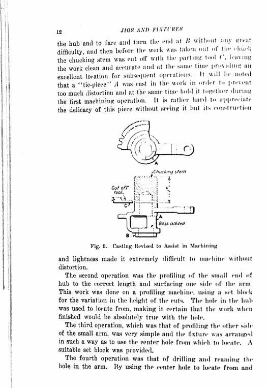
1 12
the hub and to face and turn the end at K without any mit
;
difficulty, and then before the work ww tiikrn mil if thr HiwU
I the chucking stem was cut off with the parting tun! r, l.'uvmg
the work clean and accurate and at tin* siiuw time providing an
excellent location for subsequent operations. It \ull hr nnid
f|
that a "tie-piece" A was east in the work in nnlfr to prrvrnt
too much distortion and at the same time hulil it twthrr during
the first machining operation. It in rather Itnril to apprtTtate
the delicacy of this pieec without it but its eotistnit*tum
Fig, 0, Casting Itoviwd to In
and lightness made it extremely Utdieult to tiiiirhini* without
distortion,
The Hecond operation wan the profiling of the enit f
hub to the correct length and Kurfaeinp HIM*- tf flit* iiriii
This work wan done on a profiling maehim*. it net
for the variation in the height cif flit* tuK Tin* in tin* hubwas used to locate from, making it eertain I lint the whenfinished would be absolutely true with tin* hole.
The third operation, which wan that of profiling1
flu* other fci<!i*
of the small arm, WHH very simple ami tin* fixture wn*in such a way as to use the center hole from whU*h to l<**ittt% Asuitable set block was provided.The fourth operation mm that of drilling and ttit*
hole in the arm. By using the center hole to iittcl
OUTLINE OF TOOL ENGINEERING 13
the finished surface of the arm to "bank" on it was very easyto design a jig for thin operation which gave excellent results.
The sixth operation was that of milling the inside bosses and
cutting out the tie piece. The work was located on studs in vise
jaws. These jaws were provided with stop pins which preventedthe jaws from crushing or distorting the work while the milling
operation was taking place. It was found that the work did
not spring over (U)()03 in. when the tie piece was cut out.
A great deal of thought was put on this particular piece as it
was an extremely delicate one and difficult to machine. Withthe operations as originally laid out the tools would have been
very costly and there would have been great difficulty in hold-
ing the work within the required accuracy. As the operationswere finally revised the tools were simple and comparatively
cheap and the work wan held to a close degree of accuracy with-
out difficulty.
Another Example. A very excellent example of a change in
design which resulted in a great saving in manufacture is shownin Fig, K). This may be considered an exceptional example, in
comparing the cost of the production of piece A as shown above
and H as shown below. The work is a yoke connection which
was originally made from a forging bulldozed from a machine
steel rod. The finished piece wan about 50 in. long. As origi-
nally made, the machining necessary to complete the unit was
as follows: (1) Htraddlc-mill bosses; (2) drill and ream holes.
Both the drilling and nulling operations were very awkward,due to the length of the piece. This method was followed for
some time until it was thought by tool engineers that consid-
erable improvement could be made.
After gome consideration the unit was made in two pieces as
shown at R and ('. The* yoke end was blanked in one operation
on a punch press with the holes pierced to the finished diameter.
The work wan then formed an shown, thus completing the yoke.
The next operation eonsisted of welding the yoke to a rod of
machine teel cut to the required length. Thin operation was
rapidly done1 at a smaller coat, and the only remaining work
needed to finish the piece was to dress off the welded section.
The comparative labor costs of the two method** of manufac-
ture showed a saving of !H) per cent in actual labor in the latter
method. Taking the cost into consideration the new method

14 JIQti AX!) MM'iKKN
does away with the milling cutters, drills ami reamer*,
the cost of punch-press dies just ahout fiTsi'ts fin* t'urtfimj <ijr.s
originally used, HO far an upkeep is eom'eriini,
Threaded Work. -Very often when de*i#niiitf a pi*-*1
*' of work
which is to be thread oil the designer dors imf fnkr int* t'tiiKsid*
oration the cutting1 of the thread. lit mjmut'at'tunm: wnrk the
majority of threads in cut hy itirniiH of flics, mill n urltr In
have the dien work properly they KlwuM have 11 Imtl uf af Jm^t
Fig. 10. Original and Kiwimiin Having itt
two threads. That w to nay, tho fiwt two itr
chamfered to allow tho die to run on to tti Kuw it $
evident that after two thrwub* Iti flit tlit* art* tnit likt* thmit would be impossible for It tci cut 11, full tip ! nder.
^
For this reason it in to it ofsort in the thread if to nit it to nA very good example of a dlillntlt
|ijmt ,f thn*ml*t| work mshown at A in. Fig. 11. Thin was nit t flf
*
drawing of which called for it full tliivm! tif to flu*
shoulder B. It wag a produetion job iitui it wm to I*practically impouible to cut the rlgtif up In th*

OVTLINK OF TOOL ENGINEERING- 15
as shown. A concession was finally made by the customer to
permit the thread to stop one thread away from the shoulder
and a groove was made at the point C to allow the die to runout. A little forethought on the part of the designer would have
shown him the difficulty of cutting the thread up to the shoulder
as shown and he should have made suitable provision on his
drawing to take care of this matter.
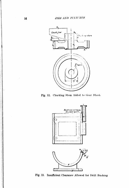
Chucking Stem on a Gear Blank, In making up spur gearblanks such as that shown at A in Fig. 12 it may bo necessary
f?\f
Fig, M. A Difficult Piece of Throidod Work, Changedto AHHittt in Production
to make several settings of the work in order to machine it prop-
erly. If, however, a chucking stem in added as shown at B in
the illustration the work ean be held by means of the chucking
stem in the chuck jaws C in such a way that all of the machin-
ing can be done in one operation. After the piece has been com-
pletely machined the parting tool I) can be run in to cut off the
blank as indicated in the illustration. An arrangement of thia
kind in very common and the same idea can be applied to manyother cawes of nimilar work.
Drilled Holes Close to a Shoulder. When drilled holes are
called for in a piece of work it; is not only necessary to provide
clearance for the drill but aim), if the work m to be, produced
in quantities, sufficient clearance should be provided for the
16 JIGS .\rt'UK8
Fig. 12, C'huc'kiiig Rtwi Atttlinl f IIi*itr
"'T:.*!!1
Fig. 18. Insufficient Cli*aiit*t* Altifwiu! for Drill

OUTLINE OF TOOL ENGINEERING! 17
drill bushing. An example of this kind is shown in Fig. 13, in
which it will be noted that the hinge hole (/ is very close to
the shoulder B. The drawing was marked **grind to wait" at
point A. Evidently the intention was to grind away the canting
slightly in order to allow clearance enough for the drill. AH a
matter of fact, when the jig was built the bushing was cut awayas shown at B, but even when this was done the variation in
the casting was so great that a proper location for the hole
could not be obtained.
The obvious remedy for a design of this kind is to cut awaythe interfering shoulder far enough so that there will he plentyof clearance for the bushing. Cases of this kind are more or
less frequent in general manufacture and it is often necessary
to make slight changes in the design in order to drill the work
correctly.

rAi*Ti;ii n
FUNDAMENTAL IN jit;
rALUK OF AN\IVJ"H l*Mt'U'|M\ i, II i , : 1% , \\ --u
AM* iNYiCrttj.* i i*>" %- f % /
ANCB FOR WoHK AM* l''<W !*< : .
CATIMO Krttmrt^ SU-HV* l *' '
TfPIS OP JlttS
There art* uumh*r *f !',', >,*.'' *
eonsidertni in tfii* ilt*%ii*!i ! lu r ^*
f-
design a ji^* Th** tti*i
only a small iiniiwiiit
ally think jf flit* ftiiin
In taking up tlfiw i
elementary iin*t cntft!jtt*itt fuiu , * ^f. r.- i
?
,
,
clear aud reailily mwlvf^iu^lA 1^ \ {*>* * *> t ^, ',. i,^-
tains a clear kmwl*tJv#* *f ih ('," '.^u^ '.!- if
, i
the design of ii%tiifr% Ii 41 *J! ^*- -/*
*<,<,
for hhttHelf inn! tn* lull 4!^Li^ <!^ >'* ,. \ ^* ,,
principle on \vhii*h li* IN ni$l/j|* si' *,' ?
Value of Irt tit iif?t<' t<
* 'i ^,-, !
the matter of 4 |i?^l,:'ii 4 *^f. . ,", , . *..
Every piwi* tif mini i* !,. ?> ,, .,
-
N
fully looked over l*|nr* m^ i^-j^,^ ,, /,<
clear undcrHtiitniiiif tif HH ^iii,f| i ri ^, -. , ,/-. k
-
various surfnf*iM mny hfMii^tr?co<| J' i -,,
consiclemhle 1^ *f<*^i*
,, .
-t
out by tht* tool fftpit^f, flwiv H<i! !
,.
'
</*r
, ,^ /, >
the tool tli*Iiii*r mn *** t^,, <*.,/ /
? ; >f
machine nn* fn tr f^^ ,Js ,-s,
- /- ,, \
analyak of tin* tiwt M^/,,, t ! M ^ * , ^, ^t -
embrace also Hit* f jign .u^i !*,*,. * s> ->,
* ,- ,

FUNVAMKXTAI* PO/XTti IN DRILL JIG DEMON li)
should consider the locution of the fins, ribs or drafts, as well
as any irregularities, in order that location points may be se-
lected which will not be subject to variations caused by rough
grinding, filing and chipping. It Is always advisable for the
tool designer to make such a thorough study of the piece of
work which he is about to tool that he can carry it in his mindwithout having to question the relations of various portions to
each other. After this analysis has been made he should be
ready to start his first jig or fixture,
Points To Be Considered. -When designing a jig the follow*
points must always be considered: the method of locating the
work HO that it will be machined in. a uniform manner; the
clearance between the jig body and the work; suitable provisionfor cleaning; chip clearance; accessibility in setting up and
removing the work; distortion in clamping, etc. Various points
in connection with those mat tern will be discussed in detail.
In locating a piece of work in a jig when no other operation
has been performed on it previously, the greatest care must be
taken to select such points for locating that inequalities in the
casting or forging will not cause the work to be thrown out of
line in such a way that subsequent operations will not give ac-
curate* results. The work may be a rough casting or forging
and while the forging may be smoother and more accurate than
the casting there in always the matter of draft to be considered.
It is advisable wherever possible for the tool designer to obtain
a Harnph* canting or forging from which to work. Not only does
thin make the tool problem more simple, but at the same time it
enables him to note when* irregularities are likely to be found
on the work and to guard against so placing a locating point
that it will come in contact with some irregular surface. In a
forging, if it happens to be a complicated one, there may be an
excessive* quantity of metal on certain parts, on account of forg-
ing conditions. Unletw the tool designer has a forging drawing,
a "lewd," or n rough forging, he may not be able to make suffi-
cient allowance in his jig or fixture to take care of the exeeftH
metal mentioned,
A fundamental principle in tool design In, that a rough casting
or forging mmt not ///* supported on more than three fixed points.
Let us consider the work shown at A in Fig. 14, which is a rough
easting of triangular shape to be drilled in the three corners
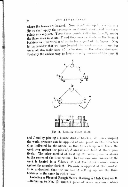
where the Inmm iw* liMti 4 l N w
jig we Hhall apply tin* pntnf^ ^ ^j
poiritH m a support. Th"- thp-1
the three holes 1), K ami I i* !j "
bushings as illttitrtitni a! H w fb
let us consider that 4 t^* IH '*
we munt alno nrnko hiiri* if tH !
Probably the
'.**'"<',
! lilt if
\4I
Vj
B r""Vf'
Jf f
4 ~;
*
/;f
MI*-;
1% 14 II. X'" 1* *i
and J ami hy n it'**l ** ! */ .i
1 I* I**,
the work, prctiKtiri* t*wii Itr 4*j!'r4 rt t s,.j
'; /
fc
*?j<?
,*'
C as indfratMl by ftn* vt ti^it ^ f /
work over Ifn* pittn II, J ii4 II
tively, Tht* citliff ^f J^^iu5^ il,. .*. /. , ^In^nin the center tif tlti illtHttittiMfi, fi s
a'?H^ < ** .n^ .M,M , | t}^
Work 18 lMfttlHl ill It If ait*! !ti- >1 ..'>M- *-/^4^
against the angtilar n ts<*^^n ^ ,,|,^,,
* ,^ *t, .1,! fIt is underKttKMl tlmt flu* ,f c*-t^ J( , t
t ^^ *^ ** it^rr
bushingK SH thi In i*ii) g^ ^i
Locating a of Itnti i**i rm It
Eeferriiig to Fijr. 15, }>..<' ,,f ^4 >* ^^n

JfUNHAUKXTAL MJWTti IN DRILL JIG DESIGN 21
has a rough hub cast on it and extending beyond the flange of
the work A. Now this piece is also a rough easting and in order
to obtain a true relation between the hub and the rest of the
easting it is necessary to use the hub in setting up the work.
By referring to the upper figure it will be seen that we do not
depart From the three point method of setting up on the pins
indicated at C. At the same time however the necessity for eon-
c,
>_ WI.___i4L'/ ""<>
(o)
{>'y,
O"
/ jL'cfrAJ *wo
'cfrtttancf
Fig, 15. Locating a Pirns of Hough Work Having a Hub Cant cm It
mdering the huh makes it advisable to provide a means for lo-
cating it on the spring V-bloeks B, By applying pressure at /)
the work will seat itself on the three points C and will also locate
in the spring V-blocks. In connection with the V-blocka men-
tioned it in well to note that these should be made with a so-
called"knife-edge.
"
Locating a Rough Forging. Very frequently rough forginga
are made with the locations of drilled holes indicated by a
countersunk npot. Fig. H) shows a gear blank with the center
hole countersunk in thin manner. In canes of this kind it is com-
mon practice to set the work up and hold it by the outside It in
a floating chuck. When this is done the chuck is placed on a
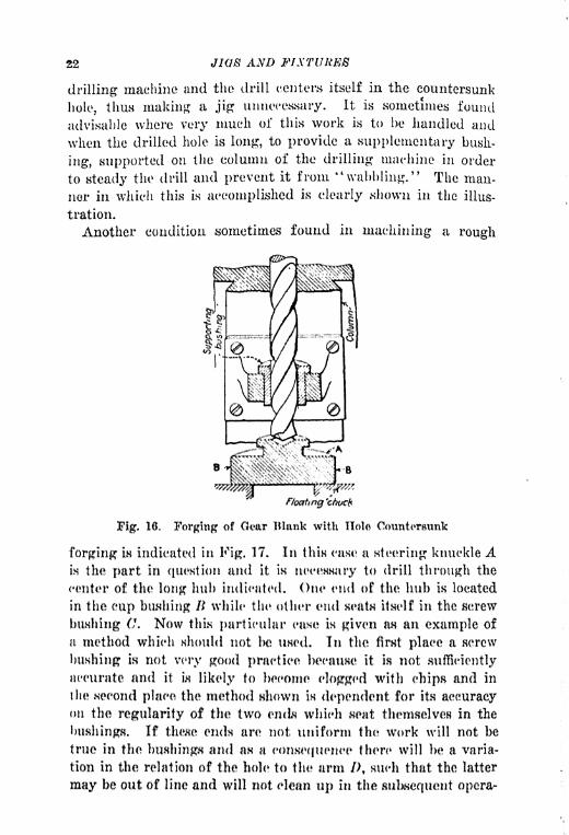
22 JIQ AND FIXTURES
drilling machine and the drill centers itself in the countersunk
hole, thus making a jig unnecessary. It is .sometimes found
advisable where very much of this work is to be handled and
when the drilled hole is long, to provide a supplementary bush-
ing, supported on the column of the drilling machine in order
to steady the drill and prevent it from "wabbling." The man-
ner in which this is accomplished is clearly shown in the illus-
tration.
Another condition sometimes found in machining a rough
floating 'ctocfi
Fig. 16. Forging of Qar Blank with Holes Countersunk
forging is indicated in Fig. 17. In this case a steering knuckle Ain the part in question and it in necessary to drill through the
center of the long hub indicated. One end of the hub m located
in the cup bushing B while the other end eat itself in the screw
bushing C. Now this particular ease in given as an example of
a method which should not Ixs used. In the first place a screw
bushing is not very good practice because it is not sufficiently
accurate and it in likely to become clogged with chips and in
the second place the method shown is dependent for its accuracyon the regularity of the two ends which themselves in the
bushings. If these ends are not uniform the work will not be
true in the bushings and as a consequence there will be a varia-
tion in the relation of the hole to the arm /), such that the latter
may be out of line and will not clean up in the subsequent opera-

FUNDAMENTAL POINTS IN DRILL JIG DESIGN 23
tion of turning the portions marked /. A much better way to
locate a forging of this sort would be to locate it with a knife-
edge V-block at each end of hub A so that when the hole Is
drilled it will be true with the hub and in correct relation to the
portion D.
Fig. 17. Incorrect Method of Locating a Forging for Drilling
Location of Finished Work. "When work has been partlymachined it is usually necessary to locate it for subBequent oppru*tions from some of the finished surfaces or holes. An exampleof this kind is shown in Fig. 18, in which the connecting rot! Ahas been previously machined as indicated by the finish
Fig. 18. Location of a Connecting Rod Forging
marks. As these surfaces have been previously faced anil nit is necessary to drill the holes E and F m that they will !Htrue with each other and with the surfaces machined, the workmust be set up with this point in mind. By allowing if to renton the bushings CO the relation desired can be readily obtain*!It is, however, necessary to obtain a location for the hole K ami

24 JIGS AND FIXTURES
at the same time make sure that this location will not disturb
the seat on the two bushings CC. This can be done by using a
V-block as shown at B having a bearing which touches the hub
above the parting line of the forging. When pressure is applied
at D the effect will be to throw the hub over into the V-block
and at the same time the angularity on the hub will tend to draw
B,
.6}
-
Fig. 19. Location of Finished Work
it down on to the bushing C. It is not usually considered good
practice to drill and ream the hole E and the small hole F in the
same operation and it is customary to locate the hole F from
.the previously machined hole E and to do the work in another
jiff-
Fig. 19 shows another method of locating finished work. It
will be noted that this piece is the same as that shown in Fig. 15,
and the operation to be done in this case is the drilling of the
long hole in the hub A. The holes B, C, and D have been drilled

FUNDAMENTAL POINTS IN DRILL JIG DESIGN 25
and reamed in a previous operation. It will be remembered
that we were careful to locate the work for the first drilling by
means of the long hub and as a consequence we can now use the
holes drilled in the previous operation for locating the piece
when drilling the long hub. By setting the work up on pins at
B and C we obtain the alignment and the stud D simply acts
as a support. If there were to be other operations on this piece
it would be advisable to use the holes B and C to locate from
through all the subsequent operations.
Fig. 20 shows another example of a method of locating a piece
Fig. 20. Location of a Finished Casting
of work of which the surface / has been machined in a
previous operation. The work is shown at A and it is located on
the finished surfaces indicated as it is necessary to keep the holes
square with the finished surfaces. At the same time we wish to
make certain that the holes are drilled in the right relation to -the
hubs E and F. Therefore we use a V-bloek 1$, slightly undercut at
an angle of about 10 deg., in which to locate the hub F. The hubE will swing over against the block C which is also slightly
undercut. Now when pressure is applied in an angular direc-
tion as indicated by the arrow at D, the work will not only seat
itself on the finished surface but will be forced over into the
V-block B and against the angular "block C thus assuring a posi-
tive and accurate location.
Correct Side from Which to Drill Holes. There is a very
important point which should always be considered in the loca-
tion of holes in two adjacent pieces, when these holes pass

26 JIQ8 &WD FIXTURES
through both pieces ami are used as rivet or bolt noles to hold
the two pieces together. An example of this kind is shown in
Fig. 21. In this case the two disks ,1 and B shown m the firnt
part of the illustration, are held together by rivets passing
through the holes C and D. It is evident then that these holes
must be in alignment Now let us assume that the work B is
placed in the jig so that it Is drilled from the side E and in the
direction indicated by the arrow. When this is done it is evi-
dent that the drill may "run" a trifle so that the holes may take
a slightly angular direction as indicated. Now if the upper
pieces A were to be drilled from the side F and in the direction
indicated by the arrow there is a possibility that these drilled
holes might also run out a trifle. The result would bo that when
BD-FJ.?._
f I Yr^y-pTrlb^([.d fo -M )
C fc ^D
fT_ff"~:
tirrTi'"o.
Fig. 21. Correct and Incorrect M<thod of Drilling Holcu In
Finished Adjacent Parts
an attempt was made to assemble the two parts A and li they
would be out of alignment and it would be impossible to put the
rivets in place to hold the two parts together.
Assuming that both parts A and R, m shown again in the
other part of the illustration, are drilled in each ease from the
sides G and H which are adjacent to eaeh other, then it is evi-
dent that at the points where the drill starts in eaeh ease the
holes will eoineide.
Distortion Caused by Improper Clamping,- -The matter of
distortion must be considered when locating and clamping any
piece of work. Several examples of this kind are shown in
Fig. 22. Referring to the tipper illustration the lever A is lo-
cated on a stud B and is clamped at the end F by means of the
clamp screw E which throws the work over against the Btud D.
Now it will be seen that when pressure is applied in the direc-
tion indicated by the arrow it cannot cause distortion or change
of shape in any way. On the other hand referring to the illus-
tration below, if the work A were to be located on a stud K with
a eliding V-bloek used as a locator and clamper, it is evident

FUNDAMENTAL POINTS JLV DRILL JIQ DKStQUf 27
that the pressure applied in the direction indicated by the arrow
might very easily tend to distort the work as shown by the dotted
lines in the lower portion of the illustration. These are points
which are frequently neglected by a tool designer.
Clearance Around Work. When designing, the matter of
clearance around the work between the walls of the jig and the
work must be given careful consideration. An example to illus
Fig 22. Correct and IncorrectLocation and Clamping
Pig. 23. Ch'nranw* AroundWork
trate this point is shown in Pig. 23. In this cane the work Ais located on a stud D placed in the body of the jig, which in
made of cast iron. Now assuming that the work A IB a canting*there is likely to be some variation in its outside dimension*; if
the jig body B is also a casting there i likely to be Home vttria
tion in its dimensions as well Therefore the clearance iw indi-
cated at C between the walls of the jig and the work fthouUI fw
ample to allow for variations in the eastings, AH a genera! thingthe distance C should never he on a small work much IIH thanf in., that is to say on a piece of work having dimension* tiltmtt
4x 6 in. On larger work whieh may run to 18 or 20 in. or ovenmore the clearance would be correspondingly greater The writerhas known of several eases within the last year where the clear-ance around rough castings of large size ha* not been
28 JIGS AND FIXTURES
to take care of variations. In one case the matter became so
serious that it involved practically the rebuilding of a large part
of an expensive trunnion jig. It is evident therefore that the
matter of clearance around the work in a jig must be given the
most careful consideration.
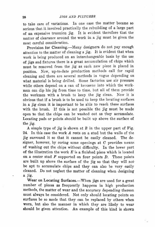
Provision for Cleaning. Many designers do not pay enough
attention to the matter of cleaning a jig. It is evident that when
work is being produced on an interchangeable basis by the use
of jigs and fixtures there is a great accumulation of chips which
must be removed from the jig as each new piece is placed in
position. Now, up-to-date production methods call for rapid
cleaning and there are several methods in vogue depending on
what material is being drilled. Some factories use air pressure
while others depend on a can of kerosene into which the work-
man can dip his jig from time to time, but all of them provide
the workman with a brush to keep the jig clean. Now it is
obvious that if a brush is to be used to keep the locating surfaces
in a jig clean it is important to be able to reach these surfaces
with the brush. If this is not possible the jig must be made
open so that the chips can be washed out as they accumulate.
Locating pads or points should be built up above the surface of
the jig.
A simple type of jig is shown at B in the upper part of Pig.
24. In this case the work A rests on a stud but the walls of the
jig surround it so that it cannot be easily cleaned. The de-
signer, however, by coring some openings at C provides means
of washing out the chips without difficulty. In the lower partof the illustration the work E is a finished piece which is located
on a center stud F supported on four points D. These pointsare built up above the surface of the jig so that they will not-
be apt to accumulate chips and they can also be very easily
cleaned. Do not neglect the matter of cleaning when designinga jig.
Wear on Locating Surfaces. When jigs are used for a greatnumber of pieces as frequently happens in high production
methods, the matter of wear and the accuracy depending thereon
must always be considered. Not only should locating points on
surfaces be so made that they can be replaced by others when
worn, but also the manner in which they are likely to wearshould be given attention. An example of this kind is shown
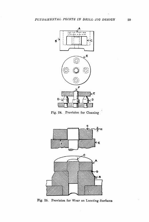
FUNDAMENTAL POINTS IN DRILL JIO DESIGN 29
Fig. 24. Provision for Cleaning
Fig. 25. Provision for Wear on Locating Surfaces

30 JW8 AND FIXTURES
in Fig. 25, in which the work A in a finished piece which locates
on the stud C and rents on the hardened locater IL Xo\v if this
locater is made slightly smaller in diameter than the work so
as to allow the latter to overhang a little all around as indicated
at D, there is no clanger of wearing & pocket or recess in the
locating member. But if it should be made as shown in the
upper part of the illustration at K it in very evident, that after
a number of pieces has been machined a pocket might be worn
Fig. 26, Method of Making Ix>cftting 8tud
in the locater as indicated at F, In a ease of this kind it would
he found that the work might take the position Hhown at and
the inaccuracy // would result. The tool designer must always
consider these points when designing hw jig.
Use of Locating Studs.- Fig. 26 nhowg two methods of mak-
ing a locating stud for use in a previously finished hole. The
work A in example R locates on the <*ylmdrieal portion C and
rests on I). Thin stud is made of one pieee and K shows the
first operation in manufacture which is clone on a lathe; and Fillustrates how the relief cuts are made by milling. The finished
plug presents a broken surface with relief cuti so that chips arc
not likely to accumulate on the surfaces*. The example shown
at G illustrates another method of making the same sort of a
locating plug, using an inserted pin instead of a solid piece,
which is often found desirable.
FUNDAMENTAL POINTS IN DRILL JIG DESIGN 31
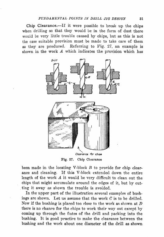
Chip Clearance. If it were possible to break up the chips
when drilling so that they would be in the form of dust there
would be very little trouble caused by chips, but as this is not
the case suitable provision must be made to take care of them
as they are produced. Referring to Fig. 27, an example is
shown in the work A which indicates the provision which has
Fig. 27. Chip Clearance
been made in the locating V-bloek B to provide for chip clear-
ance and cleaning. If this V-block extended down the entire
length of the work A it would be very difficult to clean out the
chips that might accumulate around the edges of it, but by eut-
. ting it away cus shown the trouble is avoided.
In the upper part of the illustration several examples of bush-
ings are shown. Let us assume that the work C is to be drilled.
Now if the bushing is placed too close to the work as shown at I)
there is no chance for the chips to work their way out except bycoming up through the flutes of the drill and packing into the
bushing. It is good practice to make the clearance between the
bushing and the work about one diameter of the drill as shown

32 JWM AM) JFL\TUltKti
at E. Care must be taken however not to go to extremes and
place the bushing so far away from the work that inaccuracy
may result as shown at F. In this case the bushing is so far
away from the work that the drill may run off and produce an
angular hole as Indicated.
Pig. 28. Peculiar Condition HhiHt rating Trouble Oatiwd by Chips
A peculiar case in connection with chip clearance is shown in
Fig. 28. In this ease the work which was drilled was of Ktccl
and the chips working up through the flutes of the drill became
entangled in the thumbscrew A in such a way as to loosen it,
thus releasing the work and causing inaccuracy. It in evident
that this could have been avoided by making the screw A a left-
-^. :fl
Fig. 20. Burr Clearance in a Cottar Fin Jig
hand serew, but this would not be good practice as a left-hand
screw is awkward to use,
Burr Clearance. A matter which is frequently neglected by
young designers is the making of provision for the burr which
is thrown up by a drill as it passes through the work, Tn manyeases this can be neglected as there is no burr to speak of on
cast iron or malleable iron. It in particularly noticeable how-ever on jigs for small steel pins, cotter pin jigs and the like. Anexample of this kind is shown in Pig. 29 in which the work A

FUNDAMENTAL POINTS IN DRILL <//(? 33
is to be drilled at the point B and a very simple jig has been
made to hold it. The jig is a plain block of steel C having a
strap D across it which contains a stop screw E that acts as ail
end locater. Now it will be seen that when the hole B is drilled
burrs will be thrown up around the hole at E and F and if no
provision is made for these burrs it will be very difficult to get
the work out of the jig after it has been drilled because the burnt
will prevent it. The remedy for this is to cut a groove slightly
larger than the drill diameter at the top and bottom of the jig
as shown at G. When this is done the piece can be removed
without difficulty.
Fig. 30. Size of Holes To Be Drilled in 8am t Retting
Size of Holes To Be Drilled in Same Setting. It is not
advisable to attempt to drill holes of large and small diameter**
in the same jig unless conditions are such that the jig in very
expensive and it would be costly to make other jigs. In amenof this kind it might be possible to arrange two machine* Ride
by side so that the jig can be moved from one to the other in
drilling the holes. An example of this kind is shown in Fig, SO
in which there is a series of reamed holes f in. in diameter all
around the edge of the casting, aa shown at A. It will be een
that there are also a f-in. reamed hole and a 1-in. reamed hole
in the work. It would be better praetiee to drill all of the
holes A in one jig and then to build another jig for the holeH Uand C. This point should always be considered by the tool engi-neer when laying out his operations, but occasionally it is over-looked so that the jig when made is not practical.

34 JIQ& AAW I
Setting up and Removing Work, it happens occasionally
that an inexperienced designer will design a jig and after he
has worked it up very nearly to completion lie will discover
(or some one else will discover) that he cannot get the work
into or out of the jig. Naturally this is somewhat embarrassing,
so that the point may be brought up at this time that it in well
for the designer to bear continually in mind throughout the
Fig. 31. Sit-On 0r Plate Jig
design of his jig that it is neceHHary to put Urn work into the
jig and to remove it therefrom. Suitable provision xhould be
made so that the operator can reach in ami remove Ilia work
without difficulty or eke an ejector ttbould bo provided to take
eare of the matter.
Types of Jigs. There are various typoi of in commonuse and these will bo dealt, with in detail in their proper frequence.It is not easy to make a broad diHtinction brtwwn nomo of the
types of jigs, but speaking generally they may bo divided into
the following: Plate and templet jigs; cart jig open arid dosed;

FUNDAMENTAL POINTS IN DRILL JIG DESIGN 35
built-up jigs; trunnion and indexing jigs, and standard jigs.
A brief discussion will be given of each of these types.
Plate and Templet Jigs. One of the simplest types of jigs
is a "set-on" or plate jig, illustrated in Fig. 31. Jigs of this
kind are used on heavy castings where one end is to be drilled
with a few holes and when the other end is finished so that it
can be used as a surface on which to set up the work. In the
illustration shown A is the work and B is the jig. This par-
ticular jig is made of cast iron and has a steel V-block located
Punch
Templet
U 20'
Fig. 32. Templet Jig for a Large Ring
as shown at C which is used to locate the jig in relation to a
boss on the easting. A thumbscrew D is provided at the oppo-site side in order to make the jig fast to the work and draw it
up tightly into the locating block. We might easily imaginea condition in which the hole E had been previously machined,thus allowing a plug to be dropped -.down into the hole to use
as a locator instead of working from the outside bosses with a
V-block as shown.
A templet jig is generally imed with a prick punch to locate
a series of holes on some pieces of machine work where only a
few are required. An example of this kind of jig is shown in
Pig. 32. In this ease the work A is a large ring which has a
number of holes B drilled in it here and there on the surface
of the ring. The templet jig is made of sheet metal and Is lo-
cated in the work by means of several lugs such as those shownat C. A special punch like that indicated at D is used to mark
36 J7M* AA7> F1XWRK8
the centers of the holes by placing it in the templet and striking
it a blow with a hammer. After the work has been completely
marked the templet is removed and the drilling is done on a
drilling machine.
\LJ
Fig, 33, Open Jig Tyjw*
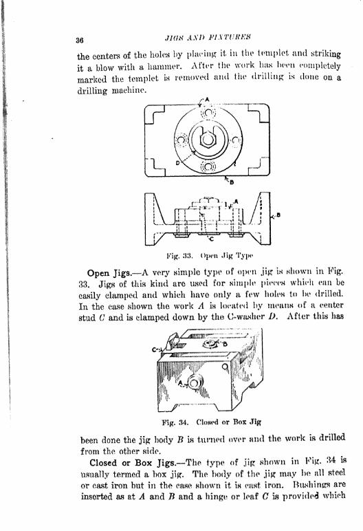
Open Jigs. A very simple type of open jig in shown in Fig.
33. Jigs of this kind are used for simple pierm which can be
easily clamped and which have only a few holes to 1m drilled.
In the ease shown the work A in ItK'ated by meaiw of a center
stud C and is clamped down by the 0-washer D. After this has
Fig. 34. Closed or Box Jig
been done the jig body B is turned over and the work is drilled
from the other side.
Closed or Box Jigs. The type of jig shown in Fig. 34 is
usually termed a box jig. The body of the jipr may be all steel
or east iron but in the ease shown it is east iron, TUwhinga are
inserted as at A and B and a hinge or leaf G w provided which
FUNDAMENTAL POINTS IN DRILL JIG DEMON 37
sometimes acts as a clamp to hold the work in place, hut mure
frequently it simply provides means for removal of the work
after it has been drilled. Jigs of this kind are commonly used
for small parts and light drilling.
'Work A
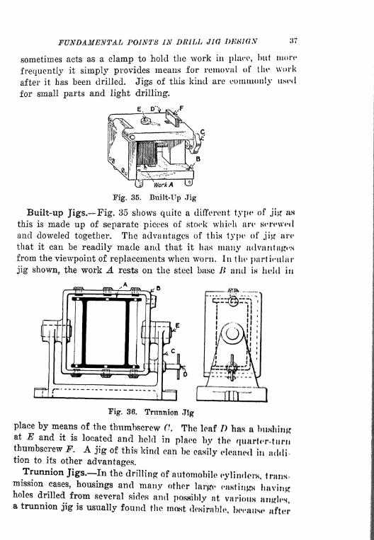
Fig. 35. Built-Up Jig
Built-up Jigs. Fig. 35 shows quite a different type1 of jikr iw
this is made up of separate pieces of stock which are Herewed
and doweled together. The advantages of this type of jig art*
that it can be readily made and that it 1ms many advantagesfrom the viewpoint of replacements when worn. In the particular
jig shown, the work A rests on the steel base K and in held in
Fig. 36. Trunnion Jig
place by means of the thumbscrew Cl The leaf D has a btwhinj?at E and it is located and held in plaee by the quart<r-turnthumbscrew F. A jig of this kind can be canily cleaned In uddition to its other advantages.Trunnion Jigs. In the drilling of automobile cylinders traiw-
mission cases, housings and many other large <-a8tinH havingholes drilled from several sides and posmbly at varioun aiitfii%a trunnion jig is usually found the mast desirable, beeiuw ftr

38 J1G8 AND FIXTURES
the work has once been placed in the jig all of the holes can be
drilled before it is removed and as a consequence correct rela-
tion between the holes will always be assured. A simple type
of trunnion jig is shown in Fig. 3ti. In this case the work A is
located in the cradle B which in its turn Is mounted on the trun-
nions at E. As the various holes are drilled the index pin D is
Fig. 37, Indexing Jig
removed and the portion It is turned over into such positions
that the desired bushings come uppermost.
The correct location is awmrecl by means of the index pin
which is generally inserted in a bushing in order to insure ae-
curacy. Trunnion jigs are made in great variety and the exam-
ple shown to illustrate the type is a very simple one,
Indexing Jigs. An indexing jig is somewhat different from
a trunnion jig in that the work is indexed into different posi-
tions for drilling a series of holes usually through the same
bushing. A ease of this kind is shown in Fig. 87 in which the

FUNDAMENTAL POINTS IN DRILL JIG
work A is located by means of some previously drilled holes in
the surface B. In this ease there are four holes to be drilled
at C and one bushing located in the bracket I) in the eorreet
relation to the center of the work. A jig of this kind in .sup-
posed td be strapped or clamped to the drilling maehine table
and the work is indexed by pulling it around until the index
pin E enters the various holes in the revolving member F*
Occasionally index jigs are made when two or more holes art*
close together and a series of the.se holes is required at equally
spaced intervals around the parts. Many methods of Indexingare in use and the example shown is a very elementary type,
Other instances will be given under their proper heading.

CHAPTER III
DETAILS OF DRILL JIG CONSTRUCTION
PLAIN CLAMPS MULTIPLE CLAMPS HOOK BOLT AND WEDGE
CLAMPS EQUALIZING CLAMPS SPRING PLUNUKRS AND JACKS
V-BLOCK DESIGN LEAF JIG DESIGNLIMP CONSTRUCTION
CLAMPS IN THE LEAF LEAF STOPS LEAF LOCKS STAND-
ARD JIGS AND COMPONENTS JIG BODIES -STANDARDIZATION
OF JIG POSTS AND THUM USOREWS J I ( J VEET~TX )CATIN G
PLUGS TYPES OF BUSHINGS HUSHING DRSIGN AND PROPOR-
TIONMETHODS OF HOLDING SLIP HUSHINGS STANDARD
KNOBS AND TnUMBaCREWS~.KjE(JT()RS.
In locating a piece of work in a jig there are several points
which must be looked after very carefully, in order that the
piece may seat itself properly, may locate against portions of
the easting which are not likely to vary and may be clamped
securely without any danger of distortion. We have gone very
thoroughly into the principles of locating the work in a previous
chapter and we have taken up the various points which influence
the design of a satisfactory jig. It must be borne in mind that
there are numberless varieties of clamps which are used for
various conditions found in jig work in many factories through-out the country and that it is the selection of the proper typeof clamp which shows the skill of the designer.
It is of primary importance that the clamp should not tend
to force the work away from the locating points when pressureis applied to it. It very frequently happens that the bearingwhich the clamp obtains on the work m not quite what it should
be and as a consequence the work is forced away from its bear-
ing and locating points so that inaccuracy is the result. In
handling delicate work it is important that the clamp should
not be applied to any portion which m likely to spring out of
shape or to be distorted, making the finished product inaccurate.
40
DETAILS OF DRILL JIG rOAVSTATT'/'/OA -H
Great care must be exercised when several damps are applied
on different portions of a piece of work. When a condition of
this kind arises the clamps must be designed in such a way that
they will equalize and distribute the pressure so that, the work
will not be tilted out of its true position.
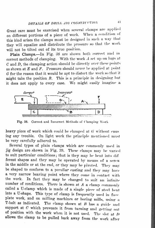
Plain Clamps. In Fig. 38 are shown both correct ami in-
correct methods of clamping. With the work A set up on lugs t
C and D, the clamping action should be directly over these points
as shown at E and F. Pressure should never he applied at point
for the reason that it would be apt to distort the* work so that It
might take the position B. This is a principle in designing; hut
it does not apply to every case. We might easily imagine u
Fig. 38. Correct and Incorrect McthodH of (MampttiK W*rk
heavy piece of work which could be clamped at (I without eauw
ing any trouble. On light work the principle mentioned muMbe very carefully adhered to.
Several types of plain clamps which are commonly uwd in
jig design are shown in Fig. 39. These clamps may lit* varied
to suit particular conditions; that Is they may be bent into dif-
ferent shapes and they may be operated by means <f a
in the middle or at the end, or they may be pivoted, They maybe shaped to conform to a peculiar canting and thiy may lv**a very narrow bearing point where they come in contact withthe work. In fact they may bo changed to Kiilt itn inflnitt*
number of conditions. There is shown at A a clump commonlycalled a U-elamp which is made of a Ringte piece of ntccl \w\\\into a U-shape. This type of clamp is frequently usid in fn*t.
plate work, and on milling machines or boring milk, tininnT-bolt as indicated. The clamp shown at /I \\m a puidi* midsupport at G which prevents it from turning and Kelt in* outof position with the work when it m not twed. The Htot it! /*allows the clamp to be pulled back away from the wr!c nfti*r

42 JIGS AND FIXTURES
the piece has been machined. This type of clamp is in commonuse for many varieties of jig work.
The clamp shown at E is similar to B but it is operated and
guided in a different manner. The operator applies pressure
,,-A -Worfr
C
-Worft
Fig. 39. Types of Plain Clamps
to the clamp by means of the thumb-knob F on the end of thescrew G. When releasing the work the screw slides along in the
groove at H. This groove also serves to keep the clamp in align-ment with the work when clamping.Hook-Bolt and Wedge Clamps. At A in Fig. 40 is shown
a hook-bolt damp, frequently found very convenient for worknot easily reached with the ordinary form of clamp, or whenthere is not room enough to permit the use of a plain clamp. Inusing a hook-bolt the heel B of the hook-bolt should be "backed-
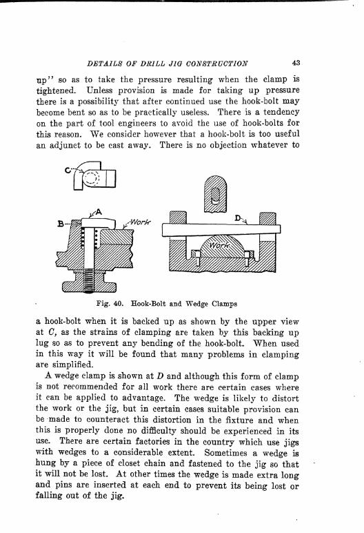
DETAILS OF DRILL JIG CONSTRUCTION 43
up'7so as to take the pressure resulting when the clamp is
tightened. Unless provision is made for taking up pressure
there is a possibility that after continued use the hook-bolt maybecome bent so as to be practically useless. There is a tendency
on the part of tool engineers to avoid the use of hook-bolts for
this reason. We consider however that a hook-bolt is too useful
an adjunct to be cast away. There is no objection whatever to
Fig. 40. Hook-Bolt and Wedge Clamps
a hook-bolt when it is backed up as shown by the upper view
at C, as the strains of clamping are taken by this backing uplug so as to prevent any bending of the hook-bolt. When used
in this way it will be found that many problems in clampingare simplified.
A wedge clamp is shown at D and although this form of clampis not recommended for all work there are certain cases whereit can be applied to advantage. The wedge is likely to distort
the work or the jig, but in certain eases suitable provision canbe made to counteract this distortion in the fixture and whenthis is properly done no difficulty should be experienced in its
use. There are certain factories in the country which use jigswith wedges to a considerable extent. Sometimes a wedge is
hung by a piece of closet chain and fastened to the jig so thatit will not be lost. At other times the wedge is made extra longand pins are inserted at each end to prevent its being lost or
falling out of the jig.
44 JIGS AND FIXTURES
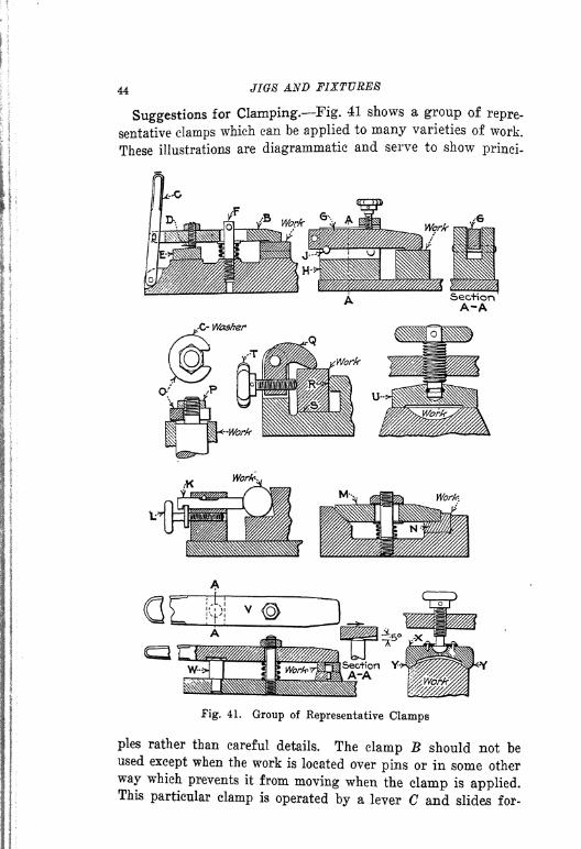
Suggestions for Clamping. Fig. 41 shows a group of repre-
sentative clamps which can be applied to many varieties of work.
These illustrations are diagrammatic and serve to show prinei-
Fig. 41. Group of Representative Clamps
pies rather than careful details. The clamp B should not beused except when the work is located over pins or in some other
way which prevents it from moving when the clamp is applied.This particular clamp is operated by a lever C and slides for-

DETAILS OF DRILL JIG CONSTRUCTION 46
ward on the work as the stud D rides up on the angular hard-
ened block E. A pin or nut on the end of the stud F takes the
pressure of the clamp.A somewhat similar arrangement is shown in the clamp G.
It is somewhat more elaborate but has the advantage of beingmade up in unit form so that it can, if necessary, be stand-
ardized and made up in quantities when the occasion warrants.
The section A-A shows another view of the block with the slid-
ing clamp in position in the block H. In operation the clampis slid forward until it comes to rest over the pin /, after which
pressure is applied by means of the thumbscrew. It is an excel-
lent clamp which is easily operated and a form similar to it is
used in great quantities by one very large manufacturing con-
cern in the Middle West.
In order to avoid throwing a piece of work out of alignmentwhen clamping, the scheme shown at K can be used. The work
locates in a V-block and the pin K is adjusted by means of the
collar screw L. This type of clamp applies the pressure directly
to the work without any turning action.
The clamp shown at M is not used frequently, but there are
occasions when a piece of work like that shown at N can be held
to advantage by this type of clamp. The objection to it is that
it must be loosened considerably in order to remove the workunless it is possible to slide the piece out of the jig end-wise.
The C-washer clamp shown at is too common to need much
description. In its simplest form it is a washer, cut out on one
side so that when the nut P is loosened it can be slipped out
readily. After this the work can be removed without difficulty
and without removing the nut.
The clamp shown at Q is very useful on small light work. It
is rapid in its action and serves to clamp the work at R and Sat the same time. When the thumbscrew T is operated equal
pressure is brought to bear in the directions indicated by the
arrows. Particular attention must be paid to the position of
the points of contact in relation to the pivot pin or more pres-
sure will probably be applied in one direction than in the other.
The clamp shown at U is commonly called a " button " clamp.It is useful for small work and is so made that the portion 17
does not revolve but is hung loosely on the end of the screw so
that when pressure is applied it adjusts itself to the work. The
46 JIGS AND FIXTURES
button may be made large or small according to conditions. It
is a useful clamp and is found in many varieties of light jig
construction.
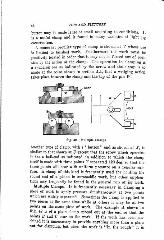
A somewhat peculiar type of clamp is shown at V whose use
is limited to finished work. Furthermore the work must be
positively located in order that it may not be forced out of posi-
tion by the action of the clamp. The operation in clamping is
a swinging one as indicated by the arrow and the clamp is so
made at the point shown in section AA, that a wedging action
takes place between the clamp and the top of the pin W.
-Work
Fig. 42. Multiple Clamps
Another type of clamp, with a"button
" end as shown at JT, is
similar to that shown at U except that the screw which operatesit has a ball-end as indicated, in addition to which the clampitself is made with three points T separated 120 deg. so that the
three points will bear with uniform pressure on a regular sur-
face. A clamp of this kind is frequently used for holding the
round end of a piston in automobile work, but other applica-tions may frequently be found in the general run of jig work.
Multiple Clamps. It is frequently necessary in clamping a
piece of work to apply pressure simultaneously at two pointswhich are widely separated. Sometimes the clamp is applied to
two pieces at the same time while at others it may be at twopoints on the same piece of work. The example A shown in
Fig. 42 is of a plain clamp spread out at the end so that the
points B and C bear on the work. If the work has been ma-chined it is unnecessary to provide anything more than a plainnut for clamping, but when the work is "in the rough
"it is

DETAILS OF DRILL JIG CONSTRUCTION 47
advisable to provide for inequalities by making the portion Din the form of a ball so as to permit the clamp to float enough
Fig. 43. Correct and Incorrect Method of Using Double End Clamps
to take care of the inequalities in the casting. The clamp E is
commonly used to hold two pieces of work at the same time as
indicated at F. It can be swung around side-wise after the workis machined to allow the pieces to be removed.
Fig. 43 shows correct and incorrect methods of using the
double end clamp. When clamps of this kind are to be used
the two points which bear against the work should be as nearlythe same distance from the center as possible. In the exag-
gerated example shown at A the clamp is so proportioned that
it would be apt to dislocate and force the work out of its cor-
rect location. The example E shows a properly designed clampfor the same piece of work.
Equalizing Clamps. When it is necessary to hold several
pieces at the same time or to apply pressure equally to three
or four pieces at the same time, an equalizing clamp must be
used. It is difficult to illustrate all of the various types of
equalizing clamps which are used in jig work, but the principles
underlying the design can be simply shown as in Fig. 44. In
the first part of the illustration, the work consists of two pieces
set up and clamped uniformly with the same screw at the sametime. When pressure is applied by means of the screw E, there
is a reaction through the lever C on the end of the pin D so as
to force the clamp E down on the work. At the same time the
reaction of the screw forces the clamp F down on to the workon that side of the jig with an equal amount of pressure.
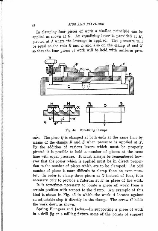
48 JIGS AND FIXTURES
In clamping four pieces of work a similar principle can be
applied as shown at G. An equalizing lever is provided at H,
pivoted at J where the leverage is applied. The pressure will
be equal on the rods K and L and also on the clanip M and Nso that the four pieces of work will be held with uniform pres-
Fig. 44. Equalizing Clamps
sure. The piece Q is clamped at both ends at the same time bymeans of the clamps R and S when pressure is applied at T.
By the addition of various levers which must be properly
pivoted it is possible to hold a number of pieces at the same
time with equal pressure. It must always be remembered how-
ever that the power which is applied must be in direct propor-tion to the number of pieces which are to be clamped. An odd
number of pieces is more difficult to clamp than an even num-ber. In order to clamp three pieces at G instead of four, it is
necessary only to provide a fulcrum at X in place of the work.
It is sometimes necessary to locate a piece of work from a
certain position with respect to the clamp. An example of this
kind is shown in Fig. 45 in which the work A locates against
an adjustable stop B directly in the clamp. The screw C holds
the work down as shown.
Spring Plungers and Jacks. In supporting a piece of workin a drill jig or a milling fixture some of the points of support

DETAILS OF DRILL JIG CONSTRUCTION 49
must be made adjustable when the work is a rough, casting.
There are also a number of cases where jacks and spring
plungers are used not only as a support but also to throw a
piece of work over into a certain position. As a general thing
spring jacks are made in such a way that they can be positively
locked after they have reached a given position, so that there
will be no chance of their moving under the pressure of a drill
or milling cutter. The locking device used to hold the jack in
position is of primary importance. Whatever method of lock-
Fig. 45. Clamp for Holding and Locating Work
ing is employed it must be such that there- is no tendency to
produce in the jack a hole or depression that might make it
likely to assume after a time one position regardless of the posi-
tion of the work against which it acts. Many ingenuous ar-
rangements are used.
There is shown at A in Fig. 46 a common type of spring jack.
Common as this type is, it is open to some objections. The
plunger or jack B is usually pack-hardened so that it has a soft
core. Therefore the action of the round end screw C has a tend-
ency, after considerable use, to make a depression or pocket as
indicated by the dotted lines at D. It is important that the
angular surface against which the screw acts should not be too
great. As a general thing about 5 deg. is sufficient. Speaking
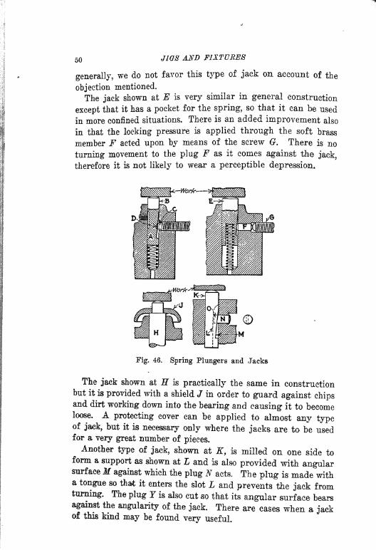
50 JIQ8 AND FIXTURES
generally, we do not favor this type of jack on account of the
objection mentioned.
The jack shown at E is very similar in general construction
except that it has a pocket for the spring, so that it can be used
In more confined situations. There is an added improvement also
in that the locking pressure is applied through the soft brass
member F acted upon by means of the screw G. There is no
turning movement to the plug F as it comes against the jack,
therefore it is not likely to wear a perceptible depression.
Fig. 46. Spring Plungers and Jacks
The jack shown at H is practically the same in constructionbut it is provided with a shield J in order to guard against chipsand dirt working down into the bearing and causing it to becomeloose. A protecting cover can be applied to almost any typeof jack, but it is necessary only where the jacks are to be usedfor a very great number of pieces.
Another type of jack, shown at K, is milled on one side toform a support as shown at L and is also provided with angularsurface M against which the plug N acts. The plug is made witha tongue so that it enters the slot L and prevents the jack fromturning. The plug 7 is also cut so that its angular surface bearsagainst the angularity of the jack. There are cases when a jackof this kind may be found very useful.
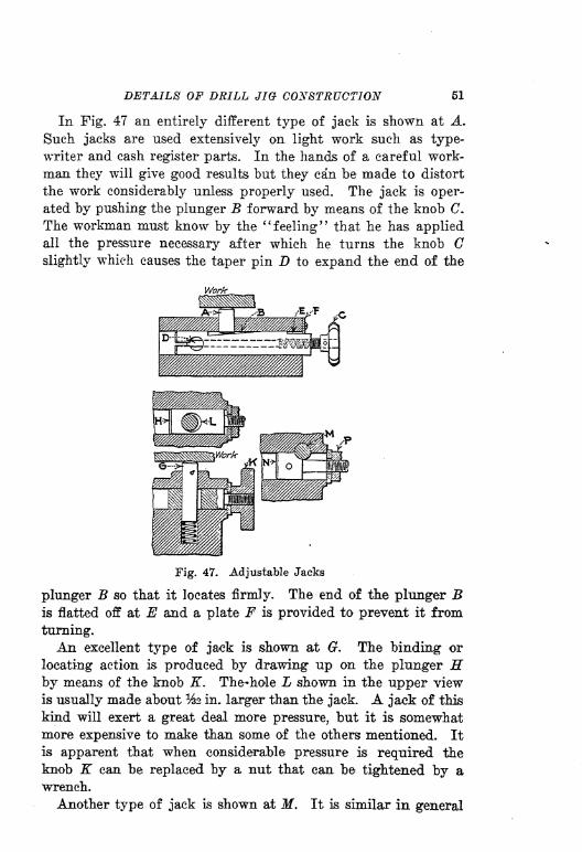
DETAILS OF DRILL JIG- CONSTRUCTION 51
In Fig. 47 an entirely different type of jack is shown at A.
Such jacks are used extensively on light work such as type-
writer and cash register parts. In the hands of a careful work-
man they will give good results but they can be made to distort
the work considerably unless properly used. The jack is oper-
ated by pushing the plunger B forward by means of the knob C.
The workman must know by the "feeling" that he has appliedall the pressure necessary after which he turns the knob Cslightly which causes the taper pin D to expand the end of the
Work
Fig. 47. Adjustable Jacks
plunger B so that it locates firmly. The end of the plunger Bis flatted off at E and a plate F is provided to prevent it from
turning.
An excellent type of ja^ck is shown at G. The binding or
locating action is produced by drawing up on the plunger Hby means of the knob K. Thehole L shown in the upper view
is usually made about %2 in. larger than the jack. A jack of this
kind will exert a great deal more pressure, but it is somewhatmore expensive to make than some of the others mentioned. It
is apparent that when considerable pressure is required the
knob K can be replaced by a nut that can be tightened by a
wrench.
Another type of jack is shown at M. It is similar in general

52 JIGS AND FIXTURES
construction to the one just described, but the location action is
somewhat different. The plunger N is concave at to the same
radius as the jack so that when pressure is applied by means of
a nut at P the friction against che jack is sufficient to keep it
from slipping. There are other designs which can be used for
spring plungers and jacks but the ones illustrated are more com-
monly used in jig work.
Fig. 48 shows a method of clamping two jacks simultaneously.
"ttf*T~~^~'
Work
Fig. 48. Locking Two Jacks at One Time
Assuming that the jacks are bearing on the work at A and B in
such a way that it is necessary to lock them at the same time in
one operation, the method shown can be used to advantage in
many cases and other developments can be made to suit par-ticular conditions. In the case shown the locking devices con-
sist of two sleeves at C and D. These sleeves are tapered slightlyon one side at the points E and F to engage with the taperedportions of the jacks A and B. Rod G extends through both of
the sleeves and is threaded at the end H so that when the knob Kis turned the two sleeves approach each other and bring equalpressures to bear on the angular portions of the jacks. A nutcan be used in place of the knob.
V-Block Design. Many types of V-blocks for locating and
clamping are found, several of which are shown in Fig. 49.

DETAILS OF DRILL JIG CONSTRUCTION 53
The type shown at A is found in every toolroom and is used for
various jobs on the milling or drilling machine. Clamping ac-
tion in setting up a piece of work, such as shown at B, should
be in the direction indicated by the arrow. It is not, however,
necessary to have the pressure of clamping through the center
of the V-bloek as it may be a trifle to one side or the other
without causing any inaccuracy in the work. Another type of
V-block, shown at C, is very useful in jig work. The angle is
slightly less than a right angle and as a consequence pressure
applied in any direction indicated by the arrows will force the
Fig. 49. Types of V-blocks
work D directly into the block. This type is commonly used for
small work.
An adjustable V-block is shown at E. The blocks F and Gare pivoted on the studs indicated and may be adjusted bymeans of the headless screws H and K. After the adjustmentthe cheek nuts must be tightened to make the location per-manent.
Still another type of adjustable Y-block, shown at L, will need
two round pins cut at an angle at the point M. This type of Vcan be adjusted by means of the check nuts. The objection to
this type, and also to that shown at E, is that there is alwaysa possibility of the nuts loosening so as to cause variation in the
location.
The principle of a sliding V-block is shown at N. The block
has a slot at which permits adjustment. Pressure can be ap-
plied through the screw P to adjust the block. An arrangementof this kind is not good on account of the opening at the slot
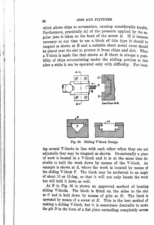
54 JIGS AND FIXTURES
which allows chips to accumulate, causing considerable trouble.
Furthermore, practically all of the pressure applied by the an-
gular jaws is taken on the head of the screw Q. If it becomes
necessary at any time to use a block of this type it should be
tongued as shown at R and a suitable sheet metal cover should
be placed over the slot to protect it from chips and dirt. Whena V-block is made like that shown at R there is always a possi-
bility of chips accumulating under the sliding portion so that
after a while it can be operated only with difficulty. For locat-
Section A-A
Fig. 50. Sliding V-block Design
ing several V-blocks in line with each other when they are not
adjustable they may be tongued as shown. Occasionally a piece
of work is located in a V-block and it is at the same time de-
sirable to hold the work down by means of the V-block. An
example is shown at S, where the work is located by means of
the sliding V-block T. The block may be undercut to an angleof about 10 or 15 deg., so that it will not only locate the workbut will hold it down as well.
At B in Fig. 50 is shown an approved method of locating
sliding V-blocks. The block is fitted on the sides to the slot
at G and is held down by means of gibs at D. The block is
operated by means of a screw at E. This is the best method of
making a sliding V-block, but it is sometimes desirable to makethe gib D in the form of a flat plate extending completely across

DETAILS OF DRILL JIG CONSTRUCTION 55
the V-bloek. Naturally these points may be varied to suit and
do not affect the fundamental features of design. Another type
of block is shown at F. There may be cases when a block of
this kind has advantages but in general it is expensive to make
and has no practical advantage over the design shown at B.
The plate G is expensive and difficult to fit.
The method of fitting a slide as shown at H is not to be com-
mended as it is much more difficult and expensive than the de-
sign shown at B. We have seen V-bloeks made in this way but
have not approved of the design. It is usually considered good
Fig. 51. Swinging V-block Design
practice to keep a design as simple as possible so as to avoid
unnecessary machining and fitting.
In Fig. 51 is shown at A a type of swinging V-block whichis quite useful on small work. Blocks of this kind are usefulwhere the work is located by a central stud on the jig. Thework shown would be difficult to locate in a regular slidingV-block. Blocks of this kind can be made up in quantities forsmall work and to a certain extent standardized so that they canbe used by simply drilling and tapping a hole for the screwshown at B and applying the block G which carries the backing-up screw.

56JIGS AND FIXTURES
Another type of swinging V-block is shown at D. The V-bloek
is made in two parts, E and F, controlled and adjusted by means
of the thumbscrew G. The thumbscrew has a shoulder at Bwhich engages with two supports on the swinging members.
This type is used to a considerable extent by a large manufac-
turer in this country.
Leaf Jigs.In the design of leaf jigs there are many points
to be considered. In the example shown in Fig. 52 the jig A
.Work
Fig. 52. Leaf Jig of Simple Design
was designed for holding the work B, while being drilled
through the portions indicated at C. The work is fastened into
the jig in one position, after which the jig is turned over until
it assumes the position shown, in which position the drilling is
done. There is no particular objection to this type of jig and
it is in common use in many factories. However, a leaf jig
design is shown at D for comparison. The leaf E is swung back
against the leaf stop indicated while the work B is being loaded
on to the stud. The leaf is then swung down into position
carrying the work with it until it takes the location shown by
the dotted lines. A quarter-turn screw F is used to locate the
leaf in position. The advantages of this type over the one at Aare that it is much more convenient to operate and if a multiple
drill-head is used, it can be clamped firmly to the correct loca-
tion on the table.
Leaf Construction. In the construction of jig leaves the
hinge is an important factor. Several methods are in vogue.
There is a straight pin such as that shown at A in the upper
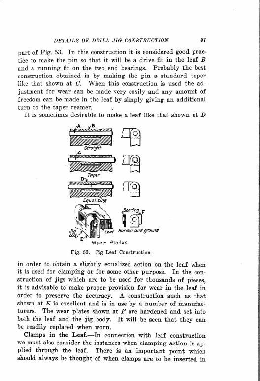
DETAILS OF DRILL JIG CONSTRUCTION 57
part of Fig. 53. In this construction it is considered good prac-
tice to make the pin so that it will be a drive fit in the leaf Band a running fit on the two end bearings. Probably the best
construction obtained is by making the pin a standard taper
like that shown at (7. When this construction is used the ad-
justment for wear can be made very easily and any amount of
freedom can be made in the leaf by simply giving an additional
turn to the taper reamer.
It is sometimes desirable to make a leaf like that shown at D
Harden aridground
Wear Ploifes
Fig. 53. Jig Leaf Construction
in order to obtain a slightly equalized action on the leaf whenit is used for clamping or for some other purpose. In the con-
struction of jigs which are to be used for thousands of pieces,
it is advisable to make proper provision for wear in the leaf in
order to preserve the accuracy. A construction such as that
shown at E is excellent and is in use by a number of manufac-turers. The wear plates shown at F are hardened and set into
both the leaf and the jig body. It will be seen that they canbe readily replaced when worn.
Clamps in the Leaf. In connection with leaf construction
we must also consider the instances when clamping action is ap-
plied through the leaf. There is an important point whichshould always be thought of when clamps are to be inserted in
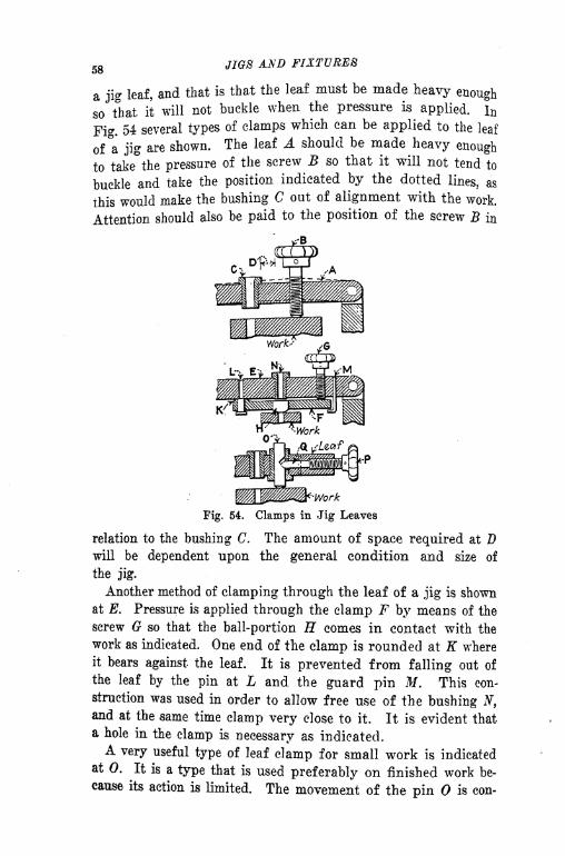
58 JIGS AND FIXTURES
a jig leaf, and that is that the leaf must be made heavy enough
so that it will not buckle when the pressure is applied. In
Fig. 54 several types of clamps which can be applied to the leaf
of a jig are shown. The leaf A should be made heavy enough
to takethe pressure of the screw B so that it will not tend to
buckle and take the position indicated by the dotted lines, as
this would make the bushing C out of alignment with the work.
Attention should also be paid to the position of the screw B in
Fig. 54. Clamps in Jig Leaves
relation to the bushing C. The amount of space required at Dwill be dependent upon the general condition and size of
the jig.
Another method of clamping through the leaf of a jig is shown
at E. Pressure is applied through the clamp F by means of the
screw G so that the ball-portion H comes in contact with the
work as indicated. One end of the clamp is rounded at K where
it bears against the leaf. It is prevented from falling out of
the leaf by the pin at L and the guard pin M. This con-
struction was used in order to allow free UvSe of the bushing N,and at the same time clamp very close to it. It is evident that
a hole in the clamp is necessary as indicated.A very useful type of leaf clamp for small work is indicated
at 0. It is a type that is used preferably on finished work be-
cause its action is limited. The movement of the pin is con-

DETAILS OF DRILL JIG CONSTRUCTION 59
trolled by the screw P acting- on the angular cut in the pin
through the plug Q, also cut to an angle on the end which en-
gages with the cut in the pin.
There are some eases where the clamp is used in a leaf when
the leaf does not carry any bushings. Referring to Fig. 55, the
sketch at A shows a leaf of this sort having a rocking clamp Bpivoted on the leaf. There are no bushings in the leaf and it is
used principally for clamping. The clamp pressure is applied
through the eye-bolt and hand knob C and D. The end of the
leaf must be slotted so that the bolt can be swung out of
Work
Fig. 55. Leaf Construction Fig. 56. Details of Jig Leaves
place in order to lift the leaf. This form of construction is verycommon and will be found useful in many cases.
When a leaf contains severalt bushings as at E the form of
construction shown is commonly used. The end of the leaf is so
slotted that the quarter-turn screw F passes through it whenthe leaf is lifted. When it is locked in position the head of the
thumbscrew binds it firmly in place.
Tn Fig. 56 several kinds of leaves are shown. Two methodsof making a hinge are indicated at A and B. In the case A the
hinge swings at A and therefore has a short bearing, while
in the other case the hinge hangs from the points C and D,which are much further apart so that greater accuracy is
assured.
A leaf like that shown at E is sometimes useful in jig con-
struction when it is necessary to place a bushing close to the

60 JIQS AND FIXTURES
work and at the same time get it out of the way while the work
is being removed. It is a good idea to provide some means of
clamping the leaf while drilling. A quarter-turn screw or some
other approved method can be used.
It is often necessary to lighten a large jig in order to expedite
the handling of it Sometimes it is advisable to make a leaf out
of aluminum as shown at F. It is a good idea to provide bush-
ings at the hinge point G and hardened plates at the end H in
order to avoid having the wear on the soft metal.
Fig. 57. Leaf Locking
Leaf Locking,. Jig leaves may be locked in a variety of ways,
several of which are shown in Fig. 57. The leaf A is fastened
by means of a quarter-turn screw B, the end of the leaf being
slotted. Wear plates at the bearing points should be pro-
vided if the jig is to be used for a great number of pieces.
Sketch C shows provision to simplify the toolmaker's work in
putting in the pin D by leaving the finished support / from

DETAILS OF DRILL JIG CONSTRUCTION 61
which to locate the jig leaf while drilling the pin hole. This
support can be machined when planing up the jig. An eye-
bolt lock for a jig leaf is shown at E. "When such a lock is
used the end of the leaf should be rounded off at F in order to
facilitate the opening. The cam lever fastening shown at G
can be used to advantage in many cases for fastening the leaf
in position. Care must be taken to make sure that the radius
E is not too small to prevent the proper locking on the pin K.
As a general thing tool designing departments have a set of
standard cam levers which give the important dimensions. Twoother types of leaf lock levers are shown at L and M. Speaking
generally the writers do not favor these forms of construction.
It must be admitted, however, that they are in use in a number
Fig. 58. Leaf Supports
of factories with more or less success. The principal objectionto their use is the fact that there is very little adjustment for
wear and they are therefore likely to become inaccurate after
they have been used a short time.*
Leaf Stops. When a jig is being used it is important to pro-vide a rest for the leaf when it is thrown back in loading or
unloading the jig. If some provision is not made there is achance that the operator may throw the leaf over and break or
strain it. Several types of leaf stops are shown in Fig. 58. Theone indicated at A is a simple type which is fastened to the wall
of the jig B so that the leaf, when swung up, comes against it
at C. Another type, shown at D, is somewhat similar, but very
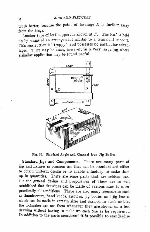
J2 JIGS AND FIXTURES
much better, because the point of leverage E is farther away
from the hinge.
Another type of leaf support is shown at F. The leaf is held
up by means of an arrangement similar to a trunk lid support.
This construction is "trappy" and possesses no particular advan-
tages. There may be 'cases, however, in a very large jig where
a similar application may be found useful.
Leaf
Fig. 59. Standard Angle and Channel Iron Jig Bodies
Standard Jigs and Components. There are many parts of
jigs and fixtures in common use that can be standardized either
to obtain uniform design or to enable a factory to make them
up in quantities. There are some parts that are seldom used
but the general design and proportions of these are so well
established that drawings can be made of various sizes to cover
practically all conditions. There are also many accessories such
as thumbscrews, hand knobs, ejectors, jig bodies and jig leaves,which can be made in certain sizes and carried in stock so that
the toolmaker can use them whenever they are shown on a tool
drawing without having to make up each one as he requires it.
In addition to the parts mentioned it is possible to standardize
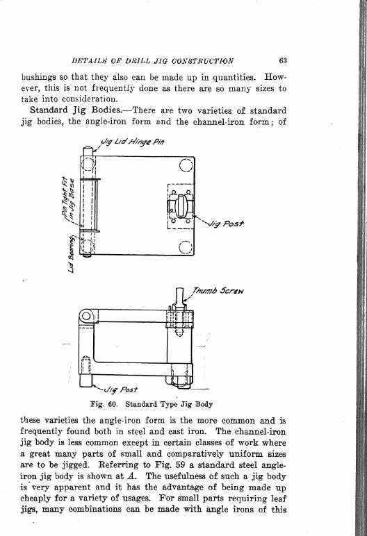
DETAILS OF DRILL JIG CONSTRUCTION 63
bushings so that they also can be made up in quantities. How-
ever, this is not frequently done as there are so many sizes to
take into consideration.
Standard Jig Bodies. There are two varieties of standard
jig bodies, the angle-iron form and the channel-iron form; of
fir
.f
r-ii
Oi
11
Fig. 60. Standard Type Jig Body
these varieties the angle-iron form is the more common and is.
frequently found both in steel and cast iron. The channel-iron
jig body is less common except in certain classes of work where
a great many parts of small and comparatively uniform sizes
are to be jigged, Eeferring to Fig. 59 a standard steel angle-
iron jig body is shown at A. The usefulness of such a jig bodyis very apparent and it has the advantage of being made upcheaply for a variety of usages. For small parts requiring leaf
jigs, many combinations can be made with angle irons of this
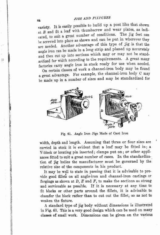
JIGS AND FIXTURES1/-X
variety It is easily possibleto build up a post like that shown
at B and fit a leaf with thumbscrew and wear plates, as indi-
cated to suit a great number of conditions. The jig feet can
be screwed into place as shown and can be put in wherever they
are needed Another advantage of this type of jig is that the
an-le iron can be made in a long strip and planed up accurately
and then cut up into sections which may or may not be stand-
ardized for width according to the requirements. A great many
factories carry angle iron in stock ready for use when needed.
On certain classes of work a channel-iron body may be found
a great advantage. For example, the channel-iron body C may
be made up in a number of sizes and may be standardized for
Fig. 61. Angle Iron Jigs Made of Cast Iron
width, depth and length. Assuming that three or four sizes are
carried in stock it is evident that a leaf may be fitted in; a
V-block or locating pin inserted; clamps put on; or other appli-
ances fitted to suit a great number of cases. In the standardiza-
tion of jig bodies the manufacturer must be governed by the
relative size of the components in his product.
It may be well to state in passing that it is advisable to pro-
vide good fillets on all angle-iron and channel-iron castings or
forgings as shown at D, E and F, to make the sections as strong
and serviceable as possible. If it is necessary at any time to
fit blocks or other parts around the fillets, it is advisable to
chamfer the block rather than to cut out the fillet,- so as not to
weaken the fixture.
A standard type of jig body without dimensions is illustrated
in Fig. 60. This is a very good design which can be used on many
classes of small work. Dimensions can be given on the various
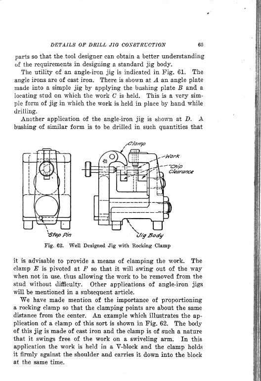
DETAILS OF DRILL JIG CONSTRUCTION 65
parts so that the tool designer can obtain a better understanding
of the requirements In designing a standard jig body.
The utility of an angle-iron jig is indicated in Fig. 61. The
angle irons are of east iron. There is shown at A an angle plate
made into a simple jig by applying the bushing plate B and a
locating stud on which the work C is held. This is a very sim-
ple form of jig in which the work is held in place by hand while
drilling.
Another application of the angle-iron jig is shown at D. Abushing of similar form is to be drilled in such quantities that
-Mark
Fig. 62. Well Designed Jig with Hocking Clamp
it is advisable to provide a means of clamping the work. The
clamp E is pivoted at F so that it will swing out of the waywhen not in use, thus allowing the work to be removed from the
stud without difficulty. Other applications of angle-iron jigs
will be mentioned in a subsequent article.
We have made mention of the importance of proportioninga rocking clamp so that the clamping points are about the same
distance from the center. An example which illustrates the ap-
plication of a clamp of this sort is shown in Fig. 62. The bodyof this jig is made of cast iron and the clamp is of such a nature
that it swings free of the work on a swiveling arm. In this
application the work is held in a V-block and the clamp holds
it firmly against the shoulder and carries it down into the block
at the same time.

66 JIGS AND FIXTURES
Advantages of Standard Jigs. Another advantage of a
standard size and form of jig is in the location of the jig whenin use on the drilling machine. Let us assume that a numberof different jigs are used from time to time and we know that
it takes a little time for the operator to arrange the machine so
that each jig will be conveniently handled. By the use of
standard jigs it is possible to clamp or screw down guides, as
indicated at A and B in Fig. 63, so that jigs of a standard size
Fig. 63. Standard Jig Used Between Guides
can be readily slipped between the guides when changing fromone part to another. In the standardization of jigs other appli-cations will be found which will prove profitable in the actual
processes of manufacture.
The same idea of using guides can be applied on large cast-iron jigs providing the sides of the jig are finished so they will
pass between the guides. In progressive drilling an arrange-ment of this sort will be found to be a great advantage.
^In taking up the various components which are used in built-up
jigs we must not forget the jig post and the frequently usedquarter-turn screw. Several examples are shown in Fig. 64.
Example A is not generally considered good practice becausethere is no locating provision made to take care of abuse or wearm the leaf. The quarter-turn screw B does not assist in loatin"
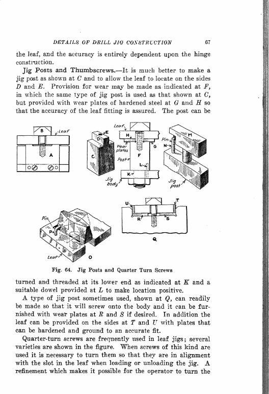
DETAILS OP DRILL JIG CONSTRUCTION 67
the leaf, and the accuracy is entirely dependent upon the hinge
constraetion.
Jig Posts and Thumbscrews. It is much better to make a
jig post as shown at C and to allow the leaf to locate on the sides
D and E. Provision for wear may be made as indicated at F,
in which the same type of jig post is used as that shown at C,
but provided with wear plates of hardened steel at and H so
that the accuracy of the leaf fitting is assured. The post can be
Lear
Fig. 64. Jig Posts and Quarter Turn Screws
turned and threaded at its lower end as indicated at K and a
suitable dowel provided at L to make location positive.
A type of jig post sometimes used, shown at Q, can readilybe made so that it will screw onto the body and it can be fur-
nished with wear plates at R and 8 if desired. In addition the
leaf can be provided on the sides at T and U with plates that
can be hardened and ground to an accurate fit.
Quarter-turn screws are frequently used in leaf jigs; several
varieties are shown in the figure. When screws of this kind are
used it is necessary to turn them so that they are in alignmentwith the slot in the leaf when loading or unloading the jig. Arefinement which makes it possible for the operator to turn the
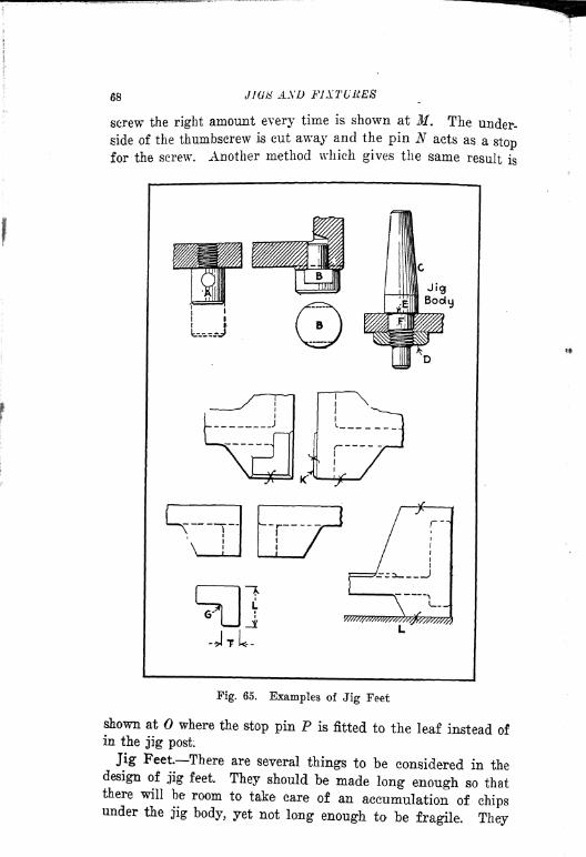
68 JWti AND FJXTURE8
screw the right amount every time is shown at M. The under-
side of the thumbscrew is cut away and the pin N acts as a stopfor the screw. Another method which gives the same result is
Fig. 65. Examples of Jig Feet
shown at where the stop pin P is fitted to the leaf instead ofin the jig post.
Jig Feet There are several things to be considered in the
design of jig feet. They should be made long enough so thatthere will be room to take care of an accumulation of chipsunder the jig body, yet not long enough to be fragile. They

DETAILS OF DRILL JIG CONSTRUCTION 69
may be screwed to the jig body, a hole being provided, as indi-
cated at Ay Fig. 65, in which a pin can be placed to assist in the
operation. Occasionally it is desirable to force in the jig feet,
instead of screwing them in place, and when this is done it is
Fig. 66. Locating Plugs
advisable to use a construction similar to that shown at B in
which flats are provided to assist in assembling.
A very excellent method of fastening jig feet in place is shownat (7, a system frequently used when a jig has to be turned or
if feet are provided on each side. The nut D can be used to
draw the foot tightly into position and its location and accuracycan be assured by the squareness of the face E and the accuracy

70JIGS AND FIXTURES
of the fit on the shank of the foot at F. It is advisable to pro-
vide means for locking the nut, consequently the thread on the
shank should be of fine pitch.
When jig feet are of cast iron it is well to make the thick-
ness T of the foot equal to the wall of the jig and the length L
about two and one-half times the thickness.
It is well to make jig feet for cast-iron jigs in the form of an
angle as indicated at 0. Attention should be paid to the pro-
portions of this angle, if the jig is a small one, in order that it
may be large enough to overlap any hole in the drilling machine
table. A construction such as that shown at H is recommended
when work is to be drilled from two sides of a cast-iron jig ; ft,
will be noted that a pad is placed at K at right angles to the jig
foot, yet on this side of the jig the foot is not built up high be-
cause it would make an awkward construction and one that
might very easily be broken. When jig feet come opposite each
other it is well to make the design similar to that shown at L,
a construction that is strong and that gives ample clearance
for chips.
Locating Plugs. Several designs of locating plugs are shown
in Fig. 66. In sketch A the plug B is made of one piece of
steel, a construction requiring considerable labor. It is much
better to use a construction similar to that shown at C in which
the plug D is used in connection wtih a hardened and ground
washer E. The locating plug is drawn up tightly by means of
the nut at F.
Care must be taken when a piece of work rests on a flat sur-
face to furnish little space for dirt and chips to accumulate.
In sketch (? a plug is shown at H and the work rests on K, cut
out in four places to give less bearing surface and to provide
clearance for the drill after it has run through the work. The
slots could be made somewhat larger and thus leave less chance
for dirt and chips to accumulate. In making up locating plugs
for use in a round hole it is advisable to relieve them so that
they will not completely fill the hole. They can be relieved as
shown at L, M or N, depending upon circumstances. The
methods shown at L and N are much to be preferred to that
shown at M. The latter tends to weaken the plug so that it is
easily broken. All plugs that are made a drive fit in a jig or
fixture must have sufficient stock that they will not loosen easily

DETAILS OF DRILL JIG CONSTRUCTION 71
when In use. The length of drive should be from two and one-
half to three times the diameter as shown at P.
In chamfering the top of a plug which is to receive a piece of
work the angle of the chamfer should be as long as can con-
veniently be made. It can be from 45 to 15 deg. on the side,
but it is much better to approach the 15-deg. angle rather
than the 45-deg. angle, as the work will assemble much more
easily and will not tend toi4coek." A diagram showing a
method used in locating a piece of work on two plugs is shown
at Q. This is a connecting rod in which the holes at the ends
ai'e held within limits of ztO.OOl in. The two plugs shown are
relieved but not correctly. The plug E can remain as it is, but
Fig. 67. Types of Bushings
that at S should be turned around 90 deg. in order to allow for
possible variations in the work.
Types of Bushings. Fig. 67 shows a number of types of
bushings used in jig construction. Bushing A, a common typehaving no head, is used almost exclusively by some factories,
but the majority prefer bushings with heads and we believe this
type to be better in the majority of eases on account of the
abuse to which bushings are subject. The bushing shown at Bis undercut at the shoulder. This is not good practice; it is
much better to round the bushing slightly as shown at C andchamfer the casting a trifle as in this way a bushing is obtainedthat is stronger and is less likely to crack or break either in useor when hardening.In the design of slip bushings the knurled form shown at D
is frequently used. It is well to state at this point that all slip
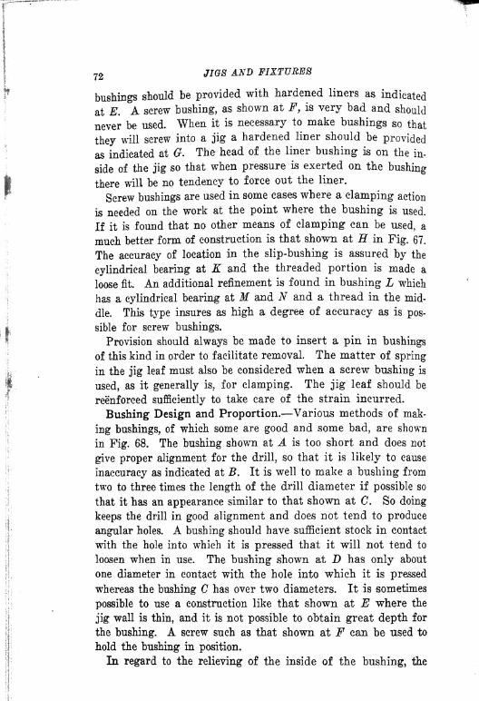
72 JIGS AND FIXTURES
bushings should be provided with hardened liners as indicated
at E. A screw bushing, as shown at F, is very bad and should
never be used. When it is necessary to make bushings so that
they will screw into a jig a hardened liner should be provided
as indicated at G. The head of the liner bushing is on the in-
side of the jig so that when pressure is exerted on the bushing
there will be no tendency to force out the liner.
Screw bushings are used in some cases where a clamping action
is needed on the work at the point where the bushing is used.
If it is found that no other means of clamping can be used, a
much better form of construction is that shown at H in Fig. 67.
The accuracy of location in the slip-bushing is assured by the
cylindrical bearing at K and the threaded portion is made a
loose fit. An additional refinement is found in bushing L which
has a cylindrical bearing at M and N and a thread in the mid-
dle. This type insures as high a degree of accuracy as is pos-
sible for screw bushings.
Provision should always be made to insert a pin in bushings
of this kind in order to facilitate removal. The matter of spring
in the jig leaf must also be considered when a screw bushing is
used, as it generally is, for clamping. The jig leaf should be
reenforeed sufficiently to take care of the strain incurred.
Bushing Design and Proportion. Various methods of mak-
ing bushings, of which some are good and some bad, are shown
in Fig. 68. The bushing shown at A is too short and does not
give proper alignment for the drill, so that it is likely to cause
inaccuracy as indicated at B. It is well to make a bushing from
two to three times the length of the drill diameter if possible so
that it has an appearance similar to that shown at C. So doing
keeps the drill in good alignment and does not tend to produce
angular holes. A bushing should have sufficient stock in contact
with the hole into which it is pressed that it will not tend to
loosen when in use. The bushing shown at D has only about
one diameter in contact with the hole into which it is pressed
whereas the bushing C has over two diameters. It is sometimes
possible to use a construction like that shown at E where the
jig wall is thin, and it is not possible to obtain great depth for
the bushing. A screw such as that shown at F can be used to
hold the bushing in position.
In regard to the relieving of the inside of the bushing, the

DETAILS OF DRILL JIG 73
form shown at G is tapered for a part of its length, a construc-
tion much better than if counterbored as shown at H because
in the latter ease the drill lip may strike the edge of the counter-
bore and cause trouble. Jig bushings are usually rounded to
facilitate the entrance of the drill as indicated at K. It is ad-
Fig. 68. Bushing Design and Proportions
visable to use a large radius in the mouth of the bushing wher-
ever possible. Data relative to the distance between the workand the bushing have been given in a previous chapter.Methods of Holding Slip Bushings. Slip bushings are used
in many eases where it is necessary to drill and ream the samehole in the same jig. The first bushing is made to the drill size
and the second bushing to the reamer size. When slip-bushingsare used provision must be made to prevent the bushing from
f!
iff!
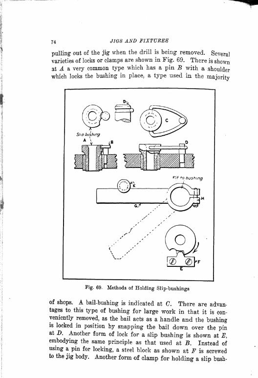
74 JIGS AND FIXTURES
pulling out of the jig when the drill is being removed. Several
varieties of locks or clamps are shown in Fig. 69. There is shownat A a very common type which has a pin B with a shoulder
which locks the bushing in place, a type used in themajority
Fig. 69. Methods of Holding Slip-bushings
of shops. A bail-bushing is indicated at C. There are advan-
tages to this type of bushing for large work in that it is con-
veniently removed, as the bail acts as a handle and the bushingis locked in position by snapping the bail down over the pinat D. Another form of lock for a slip bushing is shown at E,embodying the same principle as that used at B. Instead of
using a pin for locking, a steel block as shown at F is screwedto the jig body. Another form of clamp for holding a slip bush-

DETAILS OF DRILL Jia CONSTRUCTION 75
Ii]g is shown at G. The lever is clamped around the bushing bymeans of the pinch-binder at H and the bushing is preventedfrom pulling out of the jig by means of the retaining pin Kwhich is shouldered so that the lever passes under it. The action
of the drill tends to throw the lever against the pin K. In re-
moving the bushing the lever takes the position shown by the
dotted line.
Work
Fig. 70. Locating of Bushings
Location of Bushings. The shape of the work to be drilled
influences to some extent the location of the bushings. Thereare cases where a piece of work is so designed that it is difficult
to place the bushings so that accuracy will be assured in the
drilling operation. In the first chapter of this book the effect
of design on the machining process was commented upon to
quite an extent, and it was pointed out that the design of thework is an important factor which influences the efficiency of
jigs and fixtures. There are some tool designers who are very
ip-

76 JIGS AND FIXTURES
harsh in their criticism of the pieces for which they are called
upon to design tools and are continually suggesting changes in
their design. Changes in design are costly, especially if they
cause the changing of expensive patterns, and should not be
made unless there is something worth while to be gained.
However, it has been pointed out that there are numerous
instances when a change in design would result very profitably
to the manufacturer.
A piece of work is shown at A, Fig. 70, having an extended
hub B. The inexperienced designer would be very apt to locate
his bushings as shown at C and D, without sufficient support in
the jig body. Either of two methods can be used to avoid the
difficulty. In the method indicated at E the jig body is cut out
at F to allow the hub to pass up into it so that the bushings
G and H can be so made that they will have sufficient contact
with the jig body. Another method is indicated at K, where
the body of the jig is carried down in the form of bosses L and Mto give stock for the bushings. Provision is made for drilling
the center hole through the bushing 0.
Standard Knobs and Thumbscrews. The ability of the tool
designer is frequently shown in small ways such as the appli-
cation of thumbscrews or knobs to operate various moving parts
in the jig. It is well to consider the fact that the workman whohandles a jig or fixture has to use his hands all day long. Speak-
ing generally, a knob or thumbscrew should be so arranged that
the operator can use it without "skinning his knuckles" on some
surrounding part of the jig. The form of the knob should be
such that it will not make an operator's fingers sore.
It is advisable to avoid the use of knurled screws as far as
possible, because they tend to make an operator's fingers tender
if used frequently. The knob shown at A, Fig. 71, can be madewith as many points as desired and it can be of steel or cast
iron. If it is standardized, a number of sizes can be made upand carried in stock to suit various conditions. The hole maybe drilled so 'that it can be readily fitted to standard sizes of
screws or studs, as shown at B. A pin C is generally used to
fasten the knob in position.
Another type of knob, shown at D, can be used to advantagein numerous cases. The knob itself may have as many notches
as seem desirable, th'is being a matter for individual decision.

DETAILS OF DRILL JIG CONSTRUCTION 77
In this case the knob is made with a long hub tapped out at Eso that it can be used to pull up on a stud or down on a clamp ;
in fact it can be used in a number of ways which will suggest
themselves to the tool designer. These knobs also can be made
up in several sizes and carried in stock. A very common method
of providing a means of adjusting a screw is shown at F, where
a pin G is driven into the end of the screw to act as a handle.
Fig. 71. Standard Knobs and Thumbscrews
In the writer's opinion this construction should be used very
seldom, except when very light pressure is to be applied. The
objection to this method is that it is hard on an operator's
fingers and that he is frequently tempted to use a wrench in
order to tighten the screw;as a result the pins very soon become
bent and practically useless.
A general form of pin knob is shown at H in which the pinsare four in number and are set in at an angle. Even in this
case however there are objections to the form used for muchthe same reasons as previously stated.
A very excellent form of knob or thumbscrew is shown at K.
If
/
IIX

-o JIGS AND FIXTURESlo
This form has become a standard in many shops and is excellent
both from the viewpoint of economy and convenience of opera-
tion The knob has three points which accommodate themselves
to the operator's fingers and do not make them sore. It is a
form that can be used as a nut when drilled and tapped, or in
a manner similar to that shown at A.
A diagram which indicates the importance of clearance for
the operator's fingers is shown at L. The knob M has been so
placed that there is very little clearance for the workman's
fingers between the screws and the walls of the jig N and 0. The
amount of clearance necessary is shown by the dotted lines. It
is a very good idea for a tool designer to imagine that he is
Fig. 72. Handwheels and Large Hand Knobs
operating the jig himself, making sure that his finger clearance
is ample. At the same time he must remember that the shop
man's hands are somewhat larger than his own and he should
therefore make considerable allowance for finger clearance. The
writer has frequently seen jigs, considered good by the drafting
room, that caused the operator untold trouble, due to improper
provision for his fingers.
It should be remembered by the tool designer that the amount
of pressure to be exerted influences the size of the knob to be
used and it is sometimes found desirable to use a knurled screw
in order to prevent the application of pressure enough to distort
the work or spring it out of its true position.

DETAILS OF DRILL JIG CONSTRUCTION 79
Handwheels and Large Knobs. On large fixtures it is fre-
quently necessary to use handwheels or large knobs in order to
provide pressure sufficient to operate the mechanism. The be-
ginner is very apt to be "stingy" in the details of his design
whereas the experienced designer is "generous" and makes a*' comfortable" jig which can be used with satisfaction by the
operator.
A form of hand knob which has found a great deal of favor
with manufacturers in general is shown at A in Fig. 72. This
Fig. 73. Simple Ejector for Drill Jig
form of knob is usually made up in one or two sizes, the exam-
ple shown being the 4-in. size. A knob of this kind is used onlyon large fixtures and jigs where considerable pressure is needed.
It is generally made of cast iron and the hub is left solid so
that it can be drilled or tapped to suit particular conditions.
The advantage of this knob is that it fits the palm of the handand the fingers can go down between the points which enables
the operator to get a good grip.
On large fixtures it is often desirable to use handwheels such
as that shown at B. Handwheels of various sizes can be pur-chased cheaply and can be drilled or tapped in the hub C to suit
any particular job. It is also possible to provide the wheel
with a handle, as shown by the dotted lines at Z>, if desirable.
There may be cases where it is an advantage to notch a hand-
wheel as shown by the dotted lines at E so that an operator can

80 JIGS AND FIXTURES
get a little better grip. A handle can be put in as indicated by
the dotted lines at F to provide more leverage.
Ejectors for Drill Jigs. There are many cases when it is
essential to provide a means for removal of a piece of work
from a jig or a fixture. It is not good practice to make up a
jig in such form that the operator must use a hammer or screw-
driver to get the work out after it has been machined. A simple
form of ejector may be used, such as shown in Fig. 73. The
Wor/<'\
Locatingblock
*
Turn eccentric-
Fig. 74. Ejectors Operated by Eccentric and Wedges
work A has been placed on the locater B which it fits snugly.
To remove the work the operator would be obliged to use a
screwdriver to pry it off from the locating plug B unless pro-
vision was made for ejection. It is a very easy matter to insert
the pins as shown at C and to operate them by means of the
lever D.
There are many eases where a somewhat simpler form of
ejector can be used. The pins C could be held by a retainer and
the lever D left off entirely. The operator could provide a
wooden block on his drilling machine table and operate the
ejector by striking the pins on it.
t f

DETAILS OF DRILL JIG CONSTRUCTION 81
There are occasional cases where the removal of a piece of
work from the jig requires that considerable attention be paidto the method of removal. A case of this kind is shown in
Fig. 74 in which the work A is located on a central stud B which
it fits closely. Ejectors are formed in this instance by two pins
C and D which extend through the locating block as indicated
and rest on eccentric portions of the shaft E. When the lever Fis operated the eccentric causes the pins to rise and push tlie
work from the plug. Another method of operating a similar
mechanism is shown in the upper part of the figure. The ejector
pins G and H are operated by means of the angular surfaces
K and L on the rod P. A pin or hand knob can be providedat Q or as conditions require.
Speaking generally, the use of ejectors would be required on
any piece of work that could not be easily removed by hand.
It is advisable to consider the conditions and the necessity for
ejectors when designing any jigs in which the location is bymeans of finished surfaces, pins, or plugs. When ejectors are
used the pressure must be distributed in such a way that it will
not cause a "cramp" orli cock" in the work.

r
I !
n
CHAPTEE IV
OPEN AND CLOSED JIGS
TEMPLET JIGS PLATE JIGS OPEN JIGS FOB A SHAFT OPEN JIG
FOB A PUMP COVER CLOSED JIGS CLOSED JIGS FOR ANGULAR
AND STRAIGHT HOLES LOCATING AND ASSEMBLING JIGS
AN EXAMPLE FOR PRACTICE.
In the previous chapters we have taken up a number of points
in connection with the design of drill jigs. We shall now apply
Work:
Fig. 75. Templet Jigs
some of the principles which have been described. It is not our
intention to apply every principle or each mechanism which has
been mentioned, but rather to give a few examples of jigs of
82

OPEN AND CLOSED JIGS 83
various types to illustrate the general procedure in jig construc-
tion. From the examples given the tool designer can note vari-
ous features of importance and by careful study he can doubt-
less see other ways in which the same piece of work can be
jigged. As a matter of fact the studious designer will find it
to his advantage to consider each jig shown and endeavor to
handle the work in as many different ways as he can, applyingthe principles which have been carefully explained in the pre-
ceding chapters.
Fig. 76. Use of a Templet Jig with Locating Plug
As explained previously, the templet jig is the simplest formthat can be made. In elementary form it is sometimes nothingmore than a thin plate of steel with holes located to suit the
condition. This plate is often set on the work and marked with
a prick-punch or scriber. Templet jigs of this kind would be
made up only in cases where there were a dozen or so piecesto be drilled and also when the location of the holes did not
require very great accuracy.
Going a step further in the design of templet jigs let us con-
sider the ones shown in Fig. 75. The work A is a cast-iron
frame of large size; there are a number of holes to be drilled
on the upper surface, and there are only a few pieces to be
machined. In order to drill these cheaply and to have uni-
formity for the various pieces, the jig A is made up of sheet
metal and is furnished with three J.ocaters shown at B, C and D.
84 JIGS AND FIXTURES
The templet is placed in the position shown and clamped in
place by some convenient method, using the locaters to bring it
into the correct position. The holes are then prick-punched with
a punch similar to that shown at E, after which the templet is
removed and the work drilled according to the locations markedAnother templet jig is shown at F in which the work is an
Fig. 77. Plate Jig for a Large Casting
automobile frame. The hole G in the front spring hanger is
used as one locater for the jig and the pin H acts as the other
stop against the side of the frame. This jig is a little moreelaborate than the one previously shown as it is furnished witha thumbscrew at K to clamp it in position. Jigs of this kindmay be furnished with bushings if desired, or they may be usedwith a prick-punch to locate the holes before drilling, as in theprevious instance. It is evident that this type of jig could be
OPEN AND CLOSED JIGS 85
made much longer and carried farther along the frame to allow
for the drilling of the other holes if necessary. A method of
using a templet jig is shown in Fig. 76, the work being shown
at A and the jig at B. Let us assume that the templet has been
clamped to the work and that one hole has been drilled at C.
A convenient method of making sure that the templet does not
shift, is to use a plug like that shown at D in the first hole
drilled. After this another hole can be drilled at some distance
away as at E and a second plug inserted after which the re-
maining holes can be drilled without danger of disturbing the
location of the templet. An electric drill, indicated at F, is
convenient for work of this sort.
Plate Jigs. There is a strong family resemblance between
plate and templet jigs, yet there is a distinct difference, in that
the plate jig is often used for high production while the templet
jig is never used except when production is small. There are
many cases where a large piece of work requires a few holes to
be drilled accurately in relation to other holes which have been
previously bored and reamed and it may frequently prove to be
more economical to design a plate jig than to attempt to do the
work in a very large jig in connection with other holes. An ex-
ample of this kind is shown in Fig. 77, in which the work A is a
large casting which has been machined on the base B and on the
upper surface at C and in which the holes D and E have been
bored and reamed. It would not be economical to make a large
jig to drill the holes at F and G, especially as it is necessary to
locate them in relation respectively to the reamed holes D and E.
It will be found more economical to make up a plate such as
that shown at H, which has bushings provided at F and G and
which locates by means of the studs K and L in the reamed
holes. It is evident that a large jig of this sort would need
nothing to hold it in place as it would be quite heavy. There-
fore a handle is provided at M by which to lift it off the work
after the drilling has been done. Jigs of this kind are in com-
mon use in many factories.
In Fig. 78 is shown another application of a plate jig which,
like that in the previous instance, is located by means of a
stud A in the center hole of the work B. This stud is providedwith a key at C in order that the location of the holes D maybe in a given relation to the keyway. The location of the holes

86 JIGS AND FIXTURES
D is such that it would be difficult to support the work prop-
erly unless particular provision were made. In order to assist
in drilling, a support E is made up of cast iron so that the work
rests on it. There are occasional cases where a support of this
kind may be used in order to avoid designing an expensive jig.
Jig for a Dovetail Slide. A simple plate jig, which will give
very accurate results, is indicated in Fig. 79. The work A is
Core for Chips
Fig. 78. Plate Jig with Accessory Support
a dovetail slide which has been finished all over and in which
it is necessary to drill the four holes shown at B. These holes
must be drilled in correct relation to the dovetail and it is there-
fore necessary to locate the plate jig in the dovetail slide as in-
dicated. The jig is provided with a binder at C, operated by a
thumbknob D. The binding member is so made that it fits a
circular recess in the plate and it is evident that this forms an
excellent clamp to hold the plate in position. The end location
of the jig is obtained by means of the stop-screw shown at E.
Open Jigs. In the design of open jigs the general construc-
tion of the work to be drilled must be first considered. As a
general thing jigs of this kind are made for work which does
OPEN AND CLOSED JIGS 87
not have a great depth. Occasionally they are so arranged that
the whole jig must be turned over and the drilling done from
the side opposite that in which the piece is loaded. This usuallynecessitates drilling against the clamp and while not always
objectionable, it is considered better practice to drill against a
solid surface. In the example shown in Fig. 80 the piece of
work A has been previously reamed at B and has been milled
Fig. 79. Jig for a Dovetail Slide
on the surfaces marked /. It is necessary to locate the work so
that the hole C is in a fixed relation to the hole B which must
therefore be used as a locater. The work is set up on a stud
at B and clamped by means of a swinging C-washer D through
the nut E. It will be noted that the C-washer is pivoted so that
it will swing clear of the work. By making the washer in this
way loose pieces in the jig are avoided, which is always an
advantage. The other end of the work is located under the
bushing C by means of the sliding V-block F, operated by means
of bayonet-lock and screw-bushing shown at G. This construc-
tion allows for variations in the boss on the work at the point Cand at the same time a quarter turn of the knob H releases the
V-block and allows it to be pulled back sufficiently so that the
work can be removed from the jig. There are many cases where

S3 JIGS AND FIXTURES
If
I I
this construction is extremely valuable as it permits rapid action
and the mechanism is at the same time simple and easy to manu-
facture. This is a very good example of an open jig for a piece
of high production work and the principles illustrated can be
applied in numerous cases.
Open Jig for a Shaft. Fig. 81 shows an open jig of excel-
lent construction. The shaft A has been completely machined
before the work is drilled. It is necessary to locate the drilled
hole B at 90 deg. from the keyway in the taper at C. The work
Section Through "V Block, BushingcmcTC" Clampmp
Fig. 80. Open Jig for a Lever Arm Bracket
is placed in V-blocks and located against the stop D at one end.
The sliding member E is arranged so that it will locate in the
keyway. A cam lever shown at F is used to clamp the work.
The clamp is so made that it bears at (7 and H simultaneously.
A slot at K allows it to be slid back away from the wrork when
loading or unloading. A suggestion is made in regard to the
construction of the pin at L. Two methods can be used, the
one shown in the drawing being the cheaper. The enlarged
view at $/ shows an improved method which is more substantial
but also more expensive. The designer must be governed by the
size of the stud at L and if it is found that the pin is not suffi-
ciently strong to withstand the pressure of the cam lever, the
improved construction M can be used. A jig of this kind is
rapid and its operation makes it very convenient to handle.
The jig shown in Pig. 82 is an open jig which, however, is

OPEN AND CLOSED JIGS 89
close to the border line between the open and closed types. Thework A is a pump cover which has been machined on the sur-
faces marked /. It is to be drilled at B, C, D and E in this
operation and it is necessary that these holes should bear a cor-
rect relation to the outlet F as well as to the previously ma-
chined surface and also to the outside diameter of the work. The
Work
Elevation Showing Clamp
Fig. 81. Open Jig for a Shaft
method of locating the piece is rather out of the ordinary. The
casting rests on four hardened bushings directly under the holes
B y C, D and E and the spout F is located against the hardened
locating pin G through the action of the bevel spring plunger H.
It is also given another location, with respect to its outside
diameter, by contact with the locating pins K and L, which are
fixed in the body of the jig. After the operator closes the lever
Mywhen the work is in position, the clamp N Is screwed down
on the work by means of the thumbscrew 0. It will be seen
that this clamp is not directly above the locating bushings on
which the work rests, yet there is no danger of distortion on
account of the stiffness of the casting. The portion of the work
opposite the points K and L and mid-way between them strikes

JIQ8 AND FIXTURES
the angular surface of the spring plunger P which depresses
and at the same time insures a positive location against the
two pins K and L.
The locking of the leaf is by means of a quarter-turn screw
shown at Q. This jig is rather exceptional in its general con-
struction and may be considered as an excellent example of
modern jig design.
L-i>=>*? ^
r^xV-'t. /-.vd
Fig. 82. Open Jig for a Pump Cover
Importance of Chip-Clearance in Closed Jigs. In closed
jig design particular attention must be paid to the clearance
around the work in order to have plenty of room for chips to
accumulate, for cleaning, and for setting up and removing the
work. Wherever possible in closed jig design it is a good idea
to core openings in the side of the jig in order to allow for
cleaning. A very good example of a closed jig of simple con-
struction is shown in Fig. 83. The work A is a casting which
has been finished at / in a previous operation. There are three
blind holes to be drilled at B, C and D and it is necessary to
OPEN AND CLOSED JIGS 91
locate the work from the finished side of the casting, from the
boss around the hole D and to provide another loeater which
will come in contact with the rough casting on the side as indi-
cated at E. In the design of the jig it is well to note that the
stud E could be so made that it would be adjustable, but in this
case it has not been done because the casting is known to be a
good one and not subject to variations at this point. The boss
around the hole D locates in an adjustable V-block, the con-
Pig. 83. Closed Jig with Clamp in Leaf
struction of which has been mentioned in a previous article. Thework is clamped in position by means of the screw at the corner
adjacent to the hole C. It is advisable to set this thumbscrewat an angle of 10 or 15 deg. so that the action will tend to force
the work down on the finished surface / as well as to carry it
into its correct location. The work rests on the heads of the
three hardened bushings at B, C and D. These bushings are
slightly different from the regular type in that they are counter-
bored slightly to allow for chips while drilling. The method

92 JIGS AND FIXTURES
of clamping the work is by means of an equalizing clamp Ff
which is mounted in the leaf G. Attention is called to the fact
that the clamping action is not directly over the points in which
the work rests, but it can easily be seen that the thickness of
the casting is such that there is little likelihood of its being dis-
torted by the pressure of the clamp. The leaf is clamped by
means of the swinging eyebolt H and the thumbknob K. Care
must be taken to allow plenty of clearance at L so that there
will be no chance that the screw will strike the drilling-machine
table before the leg does. The eyebolt is so made that it will
not revolve completely on account of the end H, which strikes
the wall of the jig as the eyebolt is thrown open. When in use
this jig is turned over so that the work is drilled from the side
opposite the leaf. The jig feet N and should not be made
too long as they might interfere with the drill chuck. There
are several important points of general construction involved
in the design of this jig.
Closed Jigs for Angular and Straight Holes. "When large
castings are to be drilled from several sides, the jig is frequently
made in trunnion form, but when the work is comparatively
small it is customary to provide for drilling the holes from
various directions, by making it possible to set the jig up in
different positions as required. "When some holes are to be
drilled straight and others at an angle in the same jig, care
must be taken that projecting knobs, setscrews or other pro-
tuberances, do not strike the surface on which the jig is resting.
In Fig. 84 a closed jig is shown for the work A which has been
previously machined in a turret-lathe operation at B, C, Dand E. There are four holes to be drilled at F, arranged at the
four corners of a rectangle. There is also an angular hole to
be drilled at G. The work is located on the fixed plug H at one
end of the jig and rests on the hardened ring K. At the other
end a plug L is used as a locater. It will be noted that this
plug is arranged so that it can be operated quickly. The method
used is an application of the familiar form of bayonet-lock, the
plug being slotted at M, and the slot having an angularity at Nto provide for locking by means of the teat screw which en-
gages with the slot.
As it is necessary to locate the finished pad containing the
four holes F in such a way that the holes mentioned will be

OPEN AND CLOSED JIGS 93
square with, the finished surface, a locater must be provided.
The form of locater used is shown in an enlarged section. The
plug P is made with a double end at Q and R so that these two
points bear against the casting and straighten it up in relation
to the finished surface. The plug is mounted in a bushing and
is controlled by a spring. The end of the bushing is slotted to
Enlarged Section Showing Locater
Fig. 84. Closed Jig for Angular and Straight Holes
receive a pin 8 which keeps the locater in its correct position,
provides a means for withdrawing it when inserting the work,
and acts as a restrainer to prevent it from coming out of the
bushing. It can be seen that the action of the locater is prac-
tically automatic after the work is placed in the jig and tends to
straighten out the finished surface and thus- bring it in to its
true position while the plug L is being operated.
As originally designed four feet were provided at T and Uin order to give support while drilling the angular hole G. The
construction would be much improved by extending these feet

94 JIGS AND FIXTURES
and separating them farther, as indicated by the dottedlines,
in order to give greater stability.
Simple Type of Closed Jig. A conventional form of closed
jig is illustrated in Fig. 85. The work A locates on a hardened
plate B which is set in the body of the jig. The bushings C are
carried in the leaf. The work locates on a central stud D and
is clamped by means of C-washer E. Provision is made in the
,i
}
'
f ?1
f
I
'>
V
Fig. 85. Simple Type of Closed Jig
leaf for the nut on top of the C-washer in order to bring the
leaf as close to the work as possible. The leaf is changed by
means of a quarter-turn screw shown at F and a stop-pin is
provided at G.
Attention is called to the leaf stop indicated at H. It is also
well to note the manner in which the stud D, on which the work-
is located, is arranged and that the wall of the jig is opened upon two sides at K in order to provide for cleaning. It will also
be seen that the work does not get a bearing on the stud D for
its entire length as it is relieved at the lower portions, yet it
gives ample surface for accurate location.
A very good example which shows the application of a swing-
I

OPEN AND CLOSED JIGS 95
ing V-block to a jig is shown in Fig. 86. The work A locates
in a block B at one end of the jig while the other end is locked
and clamped by means of the two arms, C and D, operated bya thumbscrew at E. This application can be used in manycases, and the example will give the designer a number of goodideas in regard to the details of construction.
uFig. 86. Design of Jig with Swinging V-block
Built-up Jigs. A number of units frequently used in the
construction of built-up jigs have been illustrated and described
in an earlier article. In the example shown in Fig. 87 some of
these principles and units are illustrated.
The work A has been finished all over in a previous operation
and it is located on the central stud B and also in the four
pins C, D, E and F. The holes to be drilled are a blind hole
at G and three smaller holes H, K and L. The depth of the
blind hole is important and for this reason the leaf is provided

n
'*'
90 JIGS AND FIXTURES
with two hardened and ground stop-pins at M. The enlarged
view shows the type of gage used for determining the depth
of this blind hole. The hardened pins M act as stops for the
gauge block AT and the point gauges the depth of the hole. If
the hole is not deep enough the gage will not come down on
the pins, while if it is too deep the gage can be turned around
so that it will pass between the pins and strike on the sides.
Fig. 87. Built-up Jig of Representative Type
This jig is provided with a leaf stop of standard form shown
at P and the leaf is fastened by means of the quarter-turn
screw Q and bears on the wear plates indicated at R. Provi-
sion is made for stopping the quarter-turn screw by means of
the pin S. The construction of the hinge is of the approvedmethod previously described, in which a taper pin T and wear
plates at U are employed. The work is held firmly in positionon the locating studs by means of a special equalizing clampin the leaf. A sectional view of the construction is shown at V.
It will be seen that the pins W are cut on an angle at the end X

OPEN AiVD CLOSED JIGS 97
so that they exert a downward pressure on the pins which clampthe work. The action of the operating pins is limited by the
slots at so that they do not disengage completely from the
angular slot X.
This jig is built up from a standard angular plate Z and a
number of units previously described have been used in its con-
struction. It is an excellent form of jig because it can be made
up from standard units to some extent, is very easily cleaned,
quickly operated, and has every provision for adjustment and
replacement to take care of wear. It may be argued that the
clamping does not take place directly over the locating studs
but it has been pointed out that this principle cannot always be
followed, and in the case shown the work is sufficiently stiff
that no danger of distortion need be apprehended
Locating and Assembling Jigs. It is often necessary to
assemble a number of pieces on a shaft in a certain relation to
each other both radially and longitudinally. "When this is
necessary it is advisable to make use of a locating jig, an exam-
ple of which is shown in Fig. 88. The work consists of a shaft
A to which are applied several collars at B, C and D, fastened
to the shaft by means of taper pins. The jig is of cast iron
and the various units necessary are mounted on it. The shaft Ay
with collars B, C and D loosely assembled on it, is forced up-, against the hardened stud E by means of the thumbscrew F.
Each of the collars is held in position and prevented from turn-
ing by means of a screw G mounted in a block H. The screws
force the shaft over into V-blocks and longitudinal location of
the various collars is assured by the space between the various
blocks.
The principle shown at G is also used at B and D, but the
position of the unit is shown in dotted lines in order to makethe illustration more clear. The leaf K is provided with bush-
ings at L, M and N by means of which the holes are properlylocated. The work being clamped independently of the leaf, a
tapered reamer can be used to finish the holes after the leaf
has been thrown back into the position shown. Applications of
the principles shown can be used for other work of similar
character.
It is frequently necessary to locate gears, cams, levers, or other
parts on a shaft in a certain relation to each other. In cases of
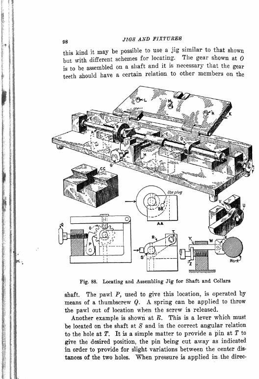
98 J1G8 AND FIXTURES
M
ii.
this kind it may be possible to use a jig similar to that shown
but with different schemes for locating. The gear shown at
is to be assembled on a shaft and it is necessary that the gear
teeth should have a certain relation to other members on the
Fig. 88. Locating and Assembling Jig for Shaft and Collars
shaft. The pawl P, used to give this location, is operated by
means of a thumbscrew Q. A spring can be applied to throw
the pawl out of location when the screw is released.
Another example is shown at R. This is a lever which must
be located on the shaft at S' and in the correct angular relation
to the hole at T. It is a simple matter to provide a pin at T to
give the desired position, the pin being cut away as indicated
in order to provide for slight variations between the center dis-
tances of the two holes. When pressure is applied in the direc-

OPEN AND CLOSED JIGS 99
tion indicated by the arrows the shaft will be forced into the
V-block and the lever will be held in its correct position.
There are some eases where a pin is assembled in the lever
arm as indicated at U. When this is the case a locating block
may be slotted as at V to receive the pin. The angularity of
this slot should be at right-angles to a center line passing
through the two holes in the lever.
A method which can be used for locating work in a V-block
is indicated at W. A swivel block X is mounted on the end of
Fig. 89. Examples for Practice in Designing Locating Jigs
a stud Y and operated by means of a collar screw Z. This typeof clamp has an advantage when it is necessary to guard against
any turning action which might change the position of the workwhen clamping. Occasionally a collar must be located on a
shaft in relation to a previously drilled hole such as that indi-
cated at AA. The work can then be located in a Y-block and
a plug can be pushed into the collar at BE. This sketch also
illustrates the slotting of a single V-block to provide for loca-
tion instead of using several blocks as indicated on the jig.
CC is also slotted but in a direction different from that in the
example just mentioned.
Example for Practice. When a series of parts is to be as-
sembled such as the cams shown at A, B, C and D in Fig. 89,
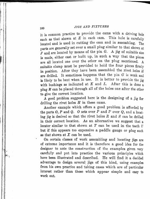
100JIGS AND FIXTURES
it is common practice to provide the cams with a driving hole
sucll ^ that shown at E in each cam. This hole iscarefully
located and is used in cutting the cam and in assembling. The
parts are generally set over a small plug similar to that shown at
F and are located by means of the pin G. A jig of suitable size
is made, either cast or built up, in such a way that the pieces
are all located one over the other on the plug mentioned. Asuitable clamp must be provided to hold the four pieces firmly
in position.After they have been assembled the rivet holes //
are drilled. It sometimes happens that the pin G is weak and
is likely to be bent when in use. It is better to provide the jig
with bushings as indicated at K and L. After this is done a
plug M can be placed through all of the holes one after the other
to give the correct location.
A good problem suggested here is the designing of a jig for
drilling the rivet holes H in these cams.
Another example which offers a good problem is afforded by
the parts 0, P and Q. sets over P and P over Q, and a locat-
ing jig is desired so that the rivet holes 72 and 8 can be drilled
in their correct location. As an alternative we suggest that a
locater similar to that shown at T can be used in the teeth Ubut if this appears too expensive a paddle gauge or plug such
as that shown at X can be used.
On certain classes of work assembling and locating jigs are
of extreme importance and it is therefore a good idea for the
designer to note the construction of the examples given very
carefully and put into practice the various principles which
have been illustrated and described. He will find it a decided
advantage to design several jigs of this kind, using examplesfrom his own practice and taking cases which are of particular
interest rather than those which appear simple and easy to
work out

CHAPTEE Y
INDEXING AND TRUNNION JIGS
INDEXING REQUIREMENTS DRILLING AND REAMING IITDEXING
FIXTURES FOUR-SIDED JIGS FOR ACCURATE WORK PRIN-
CIPLES AND METHODS OF INDEXING INDEX PLUNGERS AND
LATCHES COMBINED INDEX AND LATCH SPECIFIC EXAM-PLES OF INDEXING JIGS ROLL-OVER JIGS TRUNNION JIGS
DOUBLE TRUNNION JIG A DIFFICULT DRILLING PROBLEMTRUNNION JIG USED PROGRESSIVELY.
When a piece of work is to be drilled from three or four sides
it may often be desirable to locate it in some form of indexing
or trunnion jig. Speaking generally, the necessity for a trun-
nion jig is indicated when the work is of large size or when the
angularity of the holes would not permit the use of a closed
jig. It is evident that a large closed jig, say 20x18x15 in.,
would be very cumbersome and difficult to handle when turningit over to drill the work from the various sides. Also if the
holes in the work were to be so located that the angles did not
diverge greatly from each other, it would be practically impos-cible to drill the holes unless the pieces were located in an index
jig of some kind.
The tool engineer in making a decision as to the type of jig
to be used for the work must analyze the conditions under which
the jig is to be used and must also pay attention to the fol-
lowing points which affect the design.
Points To Be Considered. (1) The ultimate production for
which the jig will be required. This is an important factor in
the design, as it is evident that it would not be economical to
design an indexing jig for a piece of work on which the
production is small. It would be better to make several simpleand cheap jigs rather than to design one expensive trunnion
jig-
(2) The number of sides from which the work must be drilled.
101
102JIOS AND FIXTURES
It is difficult to give a fixed rule as to when a trunnion jig may
be called for and it should be noted that the number of sides
from which the work is to be drilled does not, necessarily, settle
the matter. We can easily assume that a piece of workhaving
holes in four sides might be of such form or size that it would
not need to be handled in an indexing or trunnion jig. On the
other hand if the work were very large and difficult to handle
it might even be necessary in some cases to design a trunnion
jig?even if the holes were drilled from only one side of the
piece, in order to facilitate loading and unloading.
(3) The machines on which the various drilling operations
will be done. This factor is an important one and must always
be given early consideration. There are many cases where mul-
tiple spindle drilling machines can be used in connection with
trunnion and indexing jigs, provided the holes are more or less
uniform in size. There may be other conditions which would
|indicate that a radial drilling machine must be used. There may
| also be cases where a light sensitive drilling machine with only
I one spindle or with several spindles carrying drills of different*
diameters arranged in gang-form may be necessary.
i (4) Loading and unloading: In placing the work in the jig
I and removing it after it has been drilled attention must be paid
i to the convenience of operation. If the work is heavy it is evi-
i dent that the operator must be considered to some extent so that
Ihe will not be obliged to load the work from an awkward posi-
I tion. For the sole purpose of making the method of loading
1^ and unloading as easy as possible, it is often desirable to make
a trunnion jig with a special loading position. "When the work
is small such provision is not necessary in the majority of cases.
It is sometimes a great convenience to the operator if the jig
is provided with ejectors of some form and when this is done
care must be taken that the pressure of the ejectors is exerted
in such a direction that there is no possibility of a crampingaction when in operation.
(5) Locating and clamping: In the location of the work and
in the clamping thereof the weight of the work which is to be
drilled is an important factor. For very heavy and large cast-
; ings the matter of leverage which must be exerted on the workto force it into a correct position must be carefully thought out
by the tool designer. Cam levers, handwheels, bayonet lock

INDEXING- AND TRUNNION JIGS 103
plugs and other devices may often be necessary to Insure the
correct location. In clamping the work in a large trunnion jig
the clamps should be so proportioned that when they are set up
they will not cause distortion and thus interfere with the proper
working of the jig.
(6) Clearance when indexing: This is an important point
which is likely not to be given the consideration wrhich it re-
quires. When large work is being handled on a trunnion jig it
may often be found desirable to clamp the jig to the table of
the drilling machine. It is evident that when the jig is indexed
it should not interfere with the setting of the machine spindles,
nor should it strike the column of the machine. The writers
know of a large trunnion jig, designed to be used on a heavy
drilling machine with a special multiple drill head, which when
swung interfered with the column of the machine. It was found
necessary to provide a special mounting for the base of the jig
so that it could be moved away from the column each time it
was indexed. Such mistakes can be avoided if the tool designer
will provide himself with data showing the various clearances
on the machine to be used for the work.
Having considered the various points mentioned in connec-
tion with the design of indexing and trunnion jigs let us now
proceed to a discussion of the design of various types of jigs
which come under this heading. "We may have (a) a numberof holes which are drilled so close together that it is not pos-
sible to arrange the spindles of a drilling machine to drill all
of the holes at the same time; (b) a number of holes in a cir-
cular plate at the same distance from the center; (c) several
holes in line with each other which must be drilled separately
on account of the spindle spacing on the drilling machine; (d)
a number of holes equally spaced in the periphery of a cylinder ;
(e) angular holes arranged in various ways.
Indexing Requirements. It is obvious that both the shapeof the work and the relation of the various drilled holes to each
other are factors important in determining the type of indexing
jig most suitable for a given piece of work. There are given in
Fig. 90 several examples of work showing a variety of condi-
tions: A is a circular plate having four holes B equally spacedand at the same distance from the center. There are several
ways in which this piece of work can be drilled. One way is

104JI08 AND FIXTURES
to make a drill jig with four bushings and move it about on the
table of the drilling machine so as to bring each bushing under
the spindle.Another way is to use the same jig, drilling with
a four-spindle head. Still another way is to make anindexing
jig, a suggestion for which is given in the illustration. A drill
Fig. 90. Several Examples of Work Requiring Indexing Jigs
bushing of the proper size would be fixed as shown at C and the
work would be placed on an indexing table or disk.
At D there is shown a drum in which four holes E are to be
drilled. This operation can be done in either an ordinary four-
sided jig or an indexing jig.
The plate F offers the rather exceptional problem of drilling
96 holes, J in. in diameter and \ in. c. to c. in each direction, a
problem with which we had to deal quite recently. It would be
impossible to arrange a series of drill spindles close enough to-

INDEXING AND TRUNNION JIGS 105
gether to drill all the holes at the same time, but it would be
entirely practicable to drill alternate holes in one or two lines
at the same time. Hence the logical method is to mount the
work so that it can be indexed in two directions in a horizontal
plane. Suitable provision for carrying the bushings would be
made in the jig and the required stops or indexing points on
the two slides G and H would give the various positions. The
piece K would be clamped to the table of the machine.
A number of combinations of drill spindles could be madewhen drilling a piece of this character. If the machines were
to be multiple-spindle drilling machines, the heads could be
spaced to drill alternate holes in the first line and the corre-
sponding holes in the third line. The plate could be indexed
in one direction only so that the intermediate holes could be
drilled. Several indexing operations all in one direction would
complete half of the drilling. After this the other slide operat-
ing in the other direction could be indexed progressively to com-
plete the work. It is possible to handle a piece of work of this
kind by means of automatic attachments through which the
indexing mechanism is operated by the action of the drill head
when it is lifted from the work.
Index Boring and Reaming Jig. In Fig. 91 is shown an
example of an indexing jig in which the two holes A and B are
to be bored and reamed without removing the work. Bushingscould be carried on the sliding member C or a permanent bush-
ing could be supported on the column of the machine. The workis of large size and as a consequence indexing is done by meansof lever D which operates pinion E meshing with rack F on the
sliding member C of the fixture. Location bushings are pro-
vided at G and H. The slide is shown in the neutral position.
Attention is called to the adjustable stops K and L which ap-
proximate the location as the slide is indexed from one position
to the other, thus making it easier for the operator to insert a
pin in the location bushings. This example is not intended to
show details of construction but rather the application of a
principle.
In designing a jig of this character it is advisable to makethe lever D long enough to afford easy operation. Care must
be taken that the pinion E is large enough to index the work
without too great radial motion of the lever. If the holes A

106 JIGS AND FIXTURES
and B are spaced so far apart that a very large pinion would
be required it is better to make the pinion small and provide
the lever with a reversible ratchet. Both ratchet and pinion
should as a rule be covered to exclude chips.
Swivel Index Jig. A simple form of indexing jig is indi-
cated in Fig. 92, in which the work A has two holes at B and C.
The jig itself consists of a box D pivoted at the point E. It is
indexed by means of the handle F. Hardened studs G and Hare provided to bear against the adjustable stops 7 and J. Bush-
Fig. 91. Index Jig for Boring and Reaming
ings could be provided to give more accurate location, but for
light work the method shown would give good results.
The same principle could be applied if there were three holes
instead of two, but another method of indexing would be re-
quired. It would be necessary to find the common center for
the three holes and pivot the swinging member at that point in
order that the bushings would come directly under the drill
spindle. There are certain isolated cases where such a jig would
be found very useful. A rapid indexing device could be used
and various modifications made to suit particular conditions.
It frequently happens that a piece of work similar to that
shown at A in Fig. 93 is to be drilled at two or more points
such as B and C, the holes to have an angular relation to each
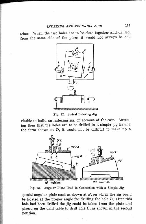
INDEXING- AND TRUNNION JIGS 107
other. When the two holes are to be close together and drilled
from the same side of the piece, it would not always be ad-
^
Fig. 92. Swivel Indexing Jig
visable to build an indexing jig, on account of the cost. Assum-
ing then that the holes are to be drilled in a simple jig having
the form shown at D, it would not be difficult to make up a
Work
Jjg
Pig. 93. Angular Plate Used in Connection with a Simple Jig
special angular plate such as shown at E, on which the jig could
be located at the proper angle for drilling the hole B/ after this
hole had been drilled the jig could be taken from the plate and
placed on the drill table to drill hole C, as shown in the second
position.

108 JIGS AND FIXTURES
If the production required on the work were considerable
the angular plate could be clamped under one spindle of a two-
spindle machine for drilling one hole and the jig could be trans-
ferred rapidly to a position on the machine table under the
second spindle for drilling the second hole.Occasionally on
very large work an angular plate, such as that shown, will save
the cost of a trunnion or indexing jig.
Four-Sided Jig for Accurate Work. The requirements of
certain classes of work are such that it is not always desirable to
use an indexing jig or fixture, especially when great accuracy
Fig. 94. Four-Sided Jig for Accurate Work
is necessary. In the majority of cases an indexing jig will give
results well within the limits of accuracy necessary, but there
are occasional instances when some other method may be pre-
ferred. There is always the possibility of a slight inaccuracy
resulting from the use of any indexing mechanism,, caused by
chips or dirt working into the indexing members or by wear,
misuse or neglect.
An example of very excellent construction to be used when
great accuracy is required is shown in Fig. 94, the piece of work
A being a cross which carries four gears on the arms. It is im-
portant, not only that these arms be at right angles but that
the locations of the center-holes in the ends of the arms should
be of the same depth and the same distance from the center hole
on which the work is located. The work is located on a center
stud and clamped by means of the C-washer, one of the arms
being located in a spring V-bloek shown at B. The jig is pro-
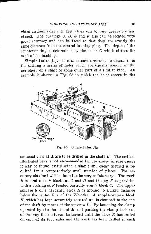
INDEXING AND TRUNNION JIGS 109
vided on four sides with feet which can be very accurately ma-
chined. The bushings G, D, E and F also can be located with
great accuracy and can be faced so that they are exactly the
same distance from the central locating plug. The depth of the
countersinking is determined by the collar G which strikes the
head of the bushing.
Simple Index Jig. It Is sometimes necessary to design a jig
for drilling a series of holes which are equally spaced in the
periphery of a shaft or some other part of a similar kind. An
example is shown in Fig. 95 in which the holes shown in the
^Section ThroughHole
3
Fig. 95. Simple Index Jig
sectional view at A are to be drilled in the shaft B. The method
illustrated here is not recommended for use except in rare cases;
it may be found useful when a simple and cheap method is re-
quired for a comparatively small number of pieces. The ac-
curacy obtained will be found to be very satisfactory. The workB is located in V-blocks at G and D and the jig E is providedwith a bushing at F located centrally over V-block C. The uppersurface G of a hardened block H is ground to a fixed distance
below the center line of the V-blocks. A supplementary block
K, which has been accurately squared up, is clamped to the end
of the shaft by means of the setscrew L. By loosening the clamp
operated by the thumb nut M and pushing the clamp back out
of the way the shaft can be turned until the block K has rested
on each of its four sides and the work has been drilled in each
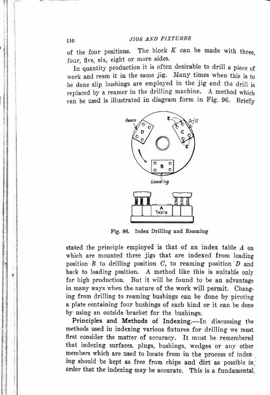
110 JIGS AND FIXTURES
of the four positions. The block K can be made withthree,
four, five, six, eight or more sides.
In quantity production it is often desirable to drill a piece of
work and ream it in the same jig. Many times when this is to
be done slip bushings are employed in the jig and the drill is
replaced by a reamer in the drilling machine. A method which
can be used is illustrated in diagram form in Fig. 96.Briefly
Ream
Loading
Fig. 96. Index Drilling and Reaming
stated the principle employed is that of an index table A on
which are mounted three jigs that are indexed from loading
position B to drilling position C, to reaming position"!) and
back to loading position. A method like this is suitable only
for high production. But it will be found to be an advantagein many ways when the nature of the work will permit. Chang-
ing from drilling to reaming bushings can be done by pivotinga plate containing four bushings of each kind or it can be done
by using an outside bracket for the bushings.
Principles and Methods of Indexing. In discussing the
methods used in indexing various fixtures for drilling we must
first consider the matter of accuracy. It must be rememberedthat indexing surfaces, plugs, bushings, wedges or any other
members which are used to locate from in the process of index-
ing should be kept as free from chips and dirt as possible in;order that the indexing may be accurate. This is a fundamental;
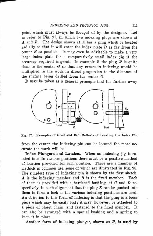
INDEXING AND TRUNNION JIGS 111
point which must always be thought of by the designer. Let
us refer to Fig. 97, in which two indexing plugs are shown at
A and B. The design shown at A has a plug which is located
radially so that it will enter the index plate D as far from the
center E as possible. It may even be advisable to make a very
large index plate for a comparatively small index jig if the
accuracy required is great. In example B the plug F is quite
close to the center G so that any errors in indexing would be
multiplied in the work in direct proportion to the distance of
the surface being drilled from the center G.
It may be taken as a general principle that the further away
Good
R,
Bad
Fig. 97. Examples of Good and Bad Methods of Locating the Index Pin
from the center the indexing pin can be located the more ac-
curate the work will be.
Index Plungers and Latches. When an indexing jig is ro-
tated into its various positions there must be a positive method
of location provided for each position. There are a number of
methods in common use, some of which are illustrated in Fig. 98.
The simplest type of indexing pin is shown by the first sketch.
A is the indexing member and B is the fixed member. Each
of them is provided with a hardened bushing, at C and D re-
spectively, in such alignment that the plug E can be pushed into
them to form a lock as the various indexing positions are used.
An objection to this form of indexing is that the plug is a loose
piece which may be easily lost; it may, however, be attached to
a piece of closet chain, and fastened to the fixed member. It
can also be arranged with a special bushing and a spring to
keep it in place.
Another form of indexing plunger, shown at F, is used by
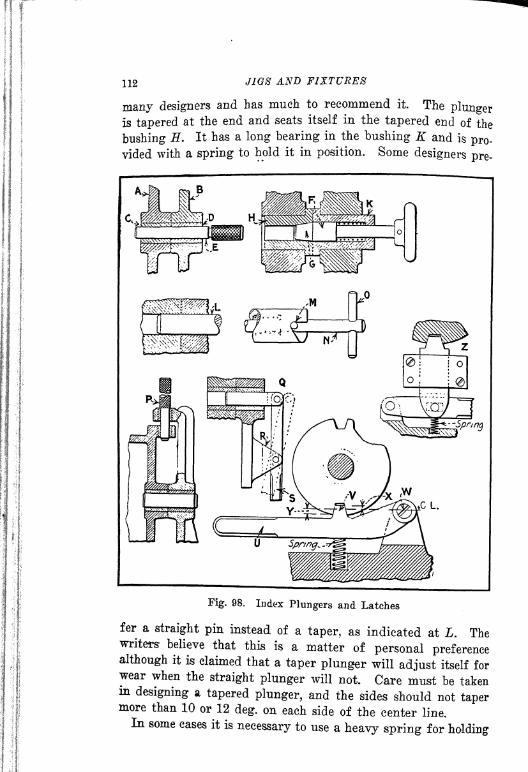
112 JIGS AND FIXTURES
many designers and has much to recommend it. The plungeris tapered at the end and seats itself in the tapered end of the
bushing ff. It has a long bearing in the bushing K and is pro-
vided with a spring to hold it in position. Some designers pre-
Fig. 98. Index Plungers and Latches
fer a straight pin instead of a taper, as indicated at L. Thewriters- believe that this is a matter of personal preferencealthough it is claimed that a taper plunger will adjust itself forwear when the straight plunger will not Care must be takenin designing a tapered plunger, and the sides should not tapermore than 10 or 12 deg. on each side of the center line.In some cases it is necessary to use a heavy spring for holding

INDEXING AND TRUNNION JIGS 113
a plunger in position ; a construction that requires considerable
pulling on the part of the operator. This can be remedied by
inserting a pin in the stem of the plunger as indicated at M and
then cutting a cam-path on the end of- -the bushing at N. The
insertion of a rod handle at the end makes it possible to pull
out the plunger by a turning action, much easier than a straight
pull.
A form of index which is much in use on large work and which
ha^ the advantage of placing the pin as far as possibls from the
center, is shown at P. There is no particular comment to be
made on this method except to say that it is good.
On large trunnion jigs it is often difficult to operate a pull-pin
by means of a knob and it is much more convenient for the
operator to provide a lever. An example is shown at Q. A lug
K is attached to the base of the fixture to act as a fulcrum for
the lever 8. The fulcrum should be so placed that the length
of the lever wrill permit the operator to withdraw the pin easily.
It is evident that an elongated slot must be provided in the
lever or the index pin to take care of radial movement when a
spring is used. Many times it is desirable to use a steel plate
instead of a bushing as an index plate, as shown at T. In one
of two methods that are common practice, the lever, as shown
at U, is formed at Y, so that it wrill seat itself in the angular
slot in the steel disk T. When an arrangement of this kind is
made the designer must be careful to position the center W so
that the distances X and Y will be equal in order that the angles
on the lever will coincide with the angles on the disk.
The other method is shown at Z. The plunger is mounted in
a slide and is operated by a lever. The second method is to be
preferred on account of its greater accuracy but space will not
always permit its use. Care should be taken that the plungeris given a long bearing in the slide in order to obtain
accuracy.
Combined Index and Latch. In indexing fixtures for high
production work and in other designs of indexing fixtures it is
desirable to make a very quick operating index and latch, one
which will be so nearly automatic that a man can operate it
rapidly and without giving it much attention. Such a latch is
shown in Fig. 99. This form can be used in many cases andcan even be arranged so that the movement of the drill press

112 JIGS AND FIXTURES
many designers and has much to recommend it. The plungeris tapered at the end and seats itself in the tapered end of the
bushing H. It has a long bearing in the bushing K and is pro-
vided with a spring to hold it in position. Some designers pre-
Fig. 98. Index Plungers and Latches
fer a straight pin instead of a taper, as indicated at L. Thewriters believe that this is a matter of personal preferencealthough it is claimed that a taper plunger will adjust itself forwear when the straight plunger will not. Care must be takenm designing a tapered plunger, and the sides should not tapermore than 10 or 12 deg. on each side of the center line.In some eases it is necessary to use a heavy spring for holding
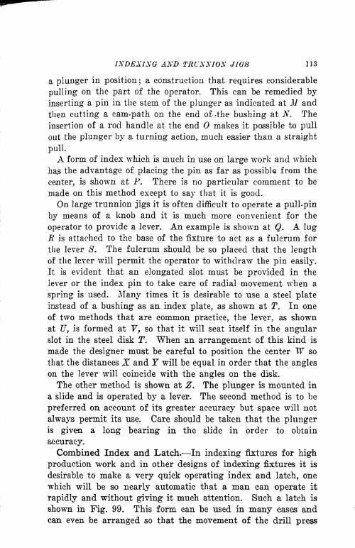
INDEXING AND TRUNNION JIGS 113
a plunger in position ;a construction that requires considerable
pulling on the part of the operator. This can be remedied by
inserting a pin in the stem of the plunger as indicated at M and
then cutting a cam-path on the end of -the bushing at N. The
insertion of a rod handle at the end makes it possible to pull
out the plunger by a turning action, much easier than a straight
pull.
A form of index which is much in use on large work and which
ha the advantage of placing the pin as far as possible from the
center, is shown at P. There is no particular comment to be
made on this method except to say that it is good.
On large trunnion jigs it is often difficult to operate a pull-pin
by means of a knob and it is much more convenient for the
operator to provide a lever. An example is shown at Q. A lugR is attached to the base of the fixture to act as a fulcrum for
the lever 8. The fulcrum should be so placed that the length
of the lever will permit the operator to withdraw the pin easily.
It is evident that an elongated slot must be provided in the
lever or the index pin to take care of radial movement when a
spring is used. Many times it is desirable to use a steel plate
instead of a bushing as an index plate, as shown at T. In one
of two methods that are common practice, the lever, as shown
at U, is formed at Y, so that it will seat itself in the angularslot in the steel disk T. When an arrangement of this kind is
made the designer must be careful to position the center W so
that the distances X and T will be equal in order that the angles
on the lever will coincide with the angles on the disk.
The other method is shown at Z. The plunger is mounted in
a slide and is operated by a lever. The second method is to be
preferred on account of its greater accuracy but space will not
always permit its use. Care should be taken that the plungeris given a long bearing in the slide in order to obtain
accuracy.
Combined Index and Latch. In indexing fixtures for high
production work and in other designs of indexing fixtures it is
desirable to make a very quick operating index and latch, one
which will be so nearly automatic that a man can operate it
rapidly and without giving it much attention. Such a latch is
shown in Fig. 99. This form can be used in many eases andcan even be arranged so that the movement of the drill press
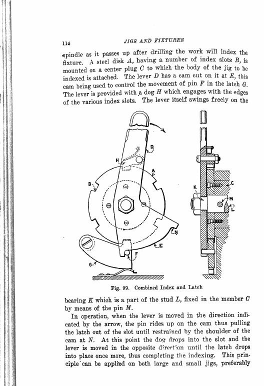
114 JIGS AND FIXTURES
spindle as it passes up after drilling the work will index the
fixture A steel disk A, having a number of index slots B, is
mounted on a center plug C to which the body of the jig to be
indexed is attached. The lever D has a cam cut on it at E, this
cam being used to control the movement of pin F in the latch 0.
The lever is provided with a dog H which engages with the edges
of the various index slots.
'
The lever itself swings freely on the
WmJ%%%^^
Fig. 99. Combined Index and Latch
bearing K which is a part of the stud L, fixed in the member G
by means of the pin M.
In operation, when the lever is moved in the direction indi-
cated by the arrow, the pin rides up on the cam thus pulling
the latch out of the slot until restrained by the shoulder of the
cam at N. At this point the dog drops into the slot and the
lever is moved in the opposite direction until the latch drops
into place once more, thus completing the indexing. This prin-
ciple 'can be applied on both large and small jigs, preferably

INDEXING AND TRUNNION JIGS 115
for indexing from four to eight stations. All of the working
parts should be hardened to insure long life and accuracy.
Index Table for Drilling. In Fig. 100 is shown a form of
indexing table which can be made up and carried in stock. It
can be used for many purposes requiring a rapid and accurate
index. Frequently, indexing of a number of holes is desirable
and yet the number of pieces to be made is small, or for some
ether reason it does not seem advisable to make up an indexing
fixture. In cases of this kind an index table can be used to
Fig. 100. Indexing Table for Drilling
advantage. A circular cast-iron base A has been faced on the
upper surface and fitted with a table B, having a center bearingby means of the plug C to which it is firmly screwed. The plughas a flange D fitted to run freely against the surface E. Ahardened shoe F is attached to the fixture at one side. Thelower part of the bearing plug is slotted to receive the indexrocker G which is pivoted loosely on the pin H. The uppersurface of the rocker is beveled to the form shown at I. Thisbevel surface acts as the index for the plate when acted on bythe spool K. The form of this spool is shown clearly in the
diagram L, and it will be noted that the flatted side allows clear-
ance for indexing. A great advantage in this type of indexingmechanism is the fact that there is clamping action of the rocker
against the hardened block.

116 JIG8 AND FIXTURES
In the particular instance illustrated, the device is made for
indexing to 180 deg., but the same principle can be used for
various numbers of index spacing by making suitable modifica-
tions in general construction. The cam K can be operated from
outside the fixture by means of a simple lever attached to the
pin M. An approximation of the indexing used can be deter-
mined by reference to the pointer at 0. The advantages of this
device are that it is accurate, very rigid in construction and all
the working parts are protected from dirt and chips.
Index Fixture for Holes in a Circle. We referred to a con-
dition in Fig. 90 in which a number of holes were drilled so
close together that drill spindles could not be spaced close
Through Center
Fig. 101. Indexing Jig for a Number of Holes Close Together in a Circle
enough to drill them all at once, and we showed a method of
handling such a condition. The holes were arranged in rec-
tangular form. We will now consider indexing jigs arranged
for a group of holes so spaced in a circle that it is not possible
to set the spindles of a drilling machine close enough together
to drill them all at one time.
Such a condition is shown in Fig. 101, the work being shown
at A and the holes indicated at B. In this jig the work is set
up and located on a central plug C and clamped in position by
means of a C-wrasher D. It rests on the three pins E, F and (?.
The bushings are spaced for alternate holes as indicated at E.
The stud on which the work is located is mounted in a revolving
plate K, supported by the base L. Indexing is done by means
of the lever M which engages with the slots N and in a hard-
ened plate. Another lever P is used to swing the index plate
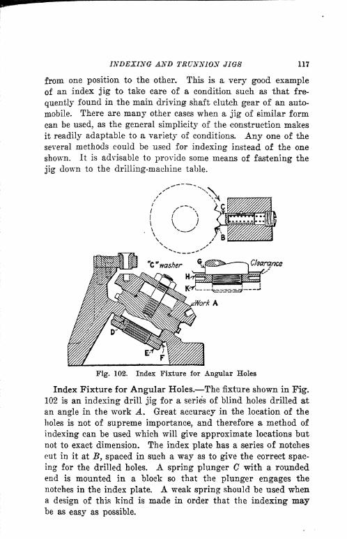
INDEXING AND TRUNNION JIOS 117
from one position to the other. This is a very good exampleof an index jig to take care of a condition such as that fre-
quently found in the main driving shaft clutch gear of an auto-
mobile. There are many other cases when a jig of similar form
can be used, as the general simplicity of the construction makes
it readily adaptable to a variety of conditions. Any one of the
several methods could be used for indexing instead of the one
shown. It is advisable to provide some means of fastening the
jig down to the drilling-machine table.
Clearance
Fig. 102. Index Fixture for Angular Holes
Index Fixture for Angular Holes. The fixture shown in Fig.
102 is an indexing drill jig for a series of blind holes drilled at
an angle in the work A. Great accuracy in the location of the
holes is not of supreme importance, and therefore a method of
indexing can be used which will give approximate locations but
not to exact dimension. The index plate has a series of notches
cut in it at B, spaced in such a way as to give the correct spac-
ing for the drilled holes. A spring plunger C with a roundedend is mounted in a block so that the plunger engages the
notches in the index plate. A weak spring should be used whena design of this kind is made in order that the indexing maybe as easy as possible.
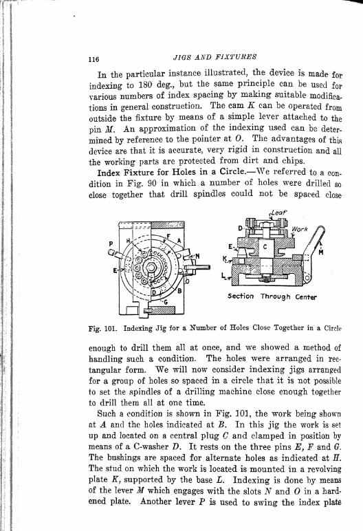
116 JIGS AND FIXTURES
In the particular instance illustrated, the device is made for
indexing to 180 deg., but the same principle can be used for
various numbers of index spacing by making suitable modifica-
tions in general construction. The cam K can be operated from
outside the fixture by means of a simple lever attached to the
pin If. An approximation of the indexing used can be deter-
mined by reference to the pointer at 0. The advantages of this
device are that it is accurate, very rigid in construction and all
the working parts are protected from dirt and chips.
Index Fixture for Holes in a Circle. We referred to a con-
dition in Fig. 90 in which a number of holes were drilled so
close together that drill spindles could not be spaced close
Section Through Center
Fig. 101. Indexing Jig for a Number of Holes Close Together in a Circle
enough to drill them all at once, and we showed a method of
handling such a condition. The holes were arranged in rec-
tangular form. We will now consider indexing jigs arranged
for a group of holes so spaced in a circle that it is not possible
to set the spindles of a drilling machine close enough together
to drill them all at one time.
Such a condition is shown in Fig. 101, the work being shown
at A and the holes indicated at B. In this jig the work is set
up and located on a central plug C and clamped in position by
means of a C-washer D. It rests on the three pins E, F and (?.
The bushings are spaced for alternate holes as indicated at H.
The stud on which the work is located is mounted in a revolving
plate K, supported by the base L. Indexing is done by means
of the lever M which engages with the slots N and in a hard-
ened plate. Another lever P is used to swing the index plate

INDEXING AND TRUNNION JIGS 117
from one position to the other. This is a very good exampleof an index jig to take care of a condition such as that fre-
quently found in the main driving shaft clutch gear of an auto-
mobile. There are many other cases when a jig of similar form
can be used, as the general simplicity of the construction makes
it readily adaptable to a variety of conditions. Any one of the
several methods could be used for indexing instead of the one
shown. It is advisable to provide some means of fastening the
jig down to the drilling-machine table.
Cfoarqnce
Fig. 102. Index Fixture for Angular Holes
Index Fixture for Angular Holes. The fixture shown in Fig.
102 is an indexing drill jig for a series of blind holes drilled at
an angle in the work A. Great accuracy in the location of the
holes is not of supreme importance, and therefore a method of
indexing can be used which will give approximate locations but
not to exact dimension. The index plate has a series of notches
cut in it at B, spaced in such a way as to give the correct spac-
ing for the drilled holes. A spring plunger C with a roundedend is mounted in a block so that the plunger engages the
notches in the index plate. A weak spring should be used whena design of this kind is made in order that the indexing maybe as easy as possible.

118 JIGS AND FIXTURES
The index plate can be mounted in either of two ways: As
shown at D it is held in place by the two locknuts E and F,
which are adjustable to permit regulation of the pressure on
the bearing and adjustment for wear. A more common method
of mounting is shown at G, where the stud is fitted so that it
comes through the hole a few thousandths and is fastened byone or two nuts as shown at H and by the dotted lines K. If
the work is to index in one direction only, one nut might be
Fig. 103. Indexing Jig for Angular Holes in a Piston
sufficient, providing the direction of the indexing is such as to
tend to tighten the nut rather than to loosen it. If the index-
ing is likely to be in both directions two nuts are necessary.In Fig. 103 is shown another angular jig for drilling a series
of angular holes in an automobile piston. The work A is lo-
cated on a stud B and drawn down against its shoulder by the
pull back rod C which is tightened by the hand knob Z>. In
tightening this rod a clamping action takes place on the pin Einserted in the wrist-pin hole.
As the angular-drilled holes need not be particularly accuratein their spacing, the indexing is done by means of the ball Fwhich snaps into notches cut around the plug G. The bushing

INDEXING AND TRUNNION JIGS 119
In this jig is carried in an overhanging arm K which forms a
part of the jig body L. The designer should pay attention to
the stability of jigs of this character and should provide a base
of sufficient dimensions so that it will be well supported.When several holes are to be drilled in a ring such as that
shown at A in Fig. 104, two methods can be used. If there is
available a multiple drill of capacity suited to the work, a sim-
ple jig can be made so that all the holes can be drilled at one
time. If, however, such a machine is not available, one solution
of the problem is to use an indexing jig. The type shown
here is exceptionally good from the indexing point of view,
L< !ft"tffQm.
s^
Fig. 104. Indexing Jig for an Annular Ring
because there is very little chance for dirt or chips to get Into
the' mechanism and thus cause errors in indexing.
The work is clamped on the locating ring B by the sliding
clamps shown at C and a bushing D is so placed that the holes
will be located the correct distance from the center of the ring.
Sufficient clearance must be allowed between the work and the
bottom of the bushing at the point E so that there will be no
difficulty in the removal of the work. The indexing mechanism
consists of a circular plate F, in the underside of which are
located the bushings G. The index plate is centered in the base
H and is held in place by the two locknuts K and L.
The index plunger M is operated by means of the lever Nwhich projects out through the side of the fixture in a location
convenient for the operator. The work can be indexed either
by pulling it around, by grasping the ring or by means of holes
in the index ring F. This type of jig is excellent for many pur-

frJIGS AND FIXTURES
f poses and the principles shown can be applied not only to driL
jigs but to other indexing fixtures for various machining opera-
tions. It should be borne in mind that the class of work for
which an index fixture is designed and the amount of pressure
which it is called upon to withstand will affect to a large extent
the general design and proportions of the fixture.
Fig. 105 shows a large jig designed for use in drilling a series
Fig. 105. Indexing Jig for Radial Rivet Holes
of holes A and B equally spaced around the periphery of an
automobile brake band. This jig is quite different in construc-
tion from any of those shown previously and it may be consid-
ered in the nature of auhorrible example." In other words it
is something which is neither practical nor well designed, yet it
is expensive and much unnecessary work is involved in its con-
struction. The entire construction is very clumsy and heavy.
A very large bearing is given to the index plate C. The index
plate and the casting E which carries the bushing, have been
made separate, for no apparent reason except the possibility of
breakage while machining the casting or on account of replace-
ment in the event of serious wear in the index plate. In addi-
tion to these points a series of bushings A and B have been lo-
cated around the periphery of the jig when two bushings that
would have answered all purposes could easily have been car-
ried on the stationary member. The only really good feature
about the fixture is the indexing mechanism which is designed
so that it can be operated by a foot pedal.

INDEXING AND TRUNNION JIGS 121
It is suggested to the student of this book that he make
an alternative design of an indexing jig for the same piece of
work, employing some of the principles which have been illus-
trated. The brake drum diameter was 14 in. and the face 3 in.
A decided improvement on the jig shown in Fig. 105 is that
illustrated in Fig. 106. A series of six slots containing three
holes each, A, B and C, are spaced equally around the periphery
of the work D. Previous to the drilling operation the work has
been bored, turned and faced and a keyway has been cut
at E. It is necessary to locate the various holes in relation
Fig. 106. Indexing Jig for a Clutch Drum
to the keyway mentioned, so the jig is made with a locater
to provide for this. The work is slipped over the locating plugF and is drawn back against the hardened locating plate G bymeans of the rod H operated by the handwheel.
Rapid removal is assisted by means of the C-washer K. Thebase L is of substantial construction and has a bearing of large
diameter in which the locating member M revolves. The correct
location of the various holes is obtained by means of the index
lever N which engages in a series of notches in the outside
diameter of the plate. The construction of the lever is some-
what similar to one of those shown in Fig. 98.
In general construction this jig embodies some good features
in design and should be studied carefully. Some of the advan-
tages are that it can be cheaply made, and can be easily ad-

122 JIGS AND FIXTURES
justed for wear by simply"papering up" under the
locating
ring G and making suitable adjustments on the bearing M.
High Production Indexing Jig. In Pig. 107 is shown anexcellent example of a high production indexing jig for a small
hub A which has a series of eight small holes drilledradially in
its outside diameter. It will be noted that the indexing mechan-ism is similar to the one illustrated in the earlier part of this
chapter. The base of the fixture B carries a spindle C which is
provided with a taper plug D so designed that it will expandthe split end of the arbor E on which the work locates. The
Washer Spring
Fig. 107. Rapid Production Indexing Jig for a Small Hub
plug is actuated by the rotation of the threaded plug F whichis operated by means of the hand knob G.
Due to the fact that the work is of a nature making removalfrom the arbor difficult, the two ejectors H and K are provided.When the operator loosens the taper plug by means of the knobG a slight blow of the hand on the knob in the direction indi-
cated by the arrow will force the work from the arbor. A slid-
ing member is provided for the knob which permits it to actafter the screw is tightened to the taper plug. This is done bymeans of a setscrew L which engages with a longitudinal slot
in the outside of the plug. An additional refinement can bemade on the ejector by using the construction shown at M. Acoil spring is interposed between the collar N and the face so

INDEXING AND TRUNNION JIGS 123
that it tends to pull the plungers back after they have been
operated. A hardened washer also can be fastened against the
face of the knob G as indicated at P. For small work producedin large quantities variations of this design will be found to
give excellent results.
Roll-Over Jigs. A piece of work may require drilling from
several sides and it may be of such a size that the jig cannot
be handled easily. The conditions may not warrant the use of
an indexing or trunnion jig and yet the production required
may make it necessary to design a fixture that can be operated
conveniently and rapidly. When a jig approaches a size 8 or 10
Fig. 108. Designs for Roll-overs
in. square and it is necessary to drill holes from several sides it
is often desirable to make provision for rolling over so that the
operator will not be obliged to lift the jig or drop it on each
side in succession. Several methods of applying "roll-overs"
are shown in Fig. 108. A is a cast form which is made as a
part of the jig itself, the corners B and C being rounded to
permit rolling the jig over on either of these sides. A flat por-
tion is provided at C to assist in loading so that the jig will not
be wobbling from side to side when the piece is being locked in
position.
D shows a roll-over of practically the same form except that
it is made as a separate piece which can be applied to the jig
body by means of screws E. A third form, shown at F, is prob-
ably the most useful and cheapest of all the varieties illustrated.
It is made from a steel strip bent to the shape shown and

124 JIGS AND FIXTURES
screwed to the body of the jig by means of TOO or more screws
<?. There is very little to be said in regard to the design of roll-
overs and the illustrations given are sufficient to cover prac-
tically all cases. The points which should be borne in mind are
that the roll-over must be so constructed that it will operate
easily and at the same time not interfere with any extensions
or lugs on the jig or interfere with loading in any way.
In Fig. 109 is shown aa outline example of a roll-over jig of
simple construction embodying the principles just mentioned
The work A is located on a central stud B and by a nut and
C-washer C. The requirements of the work are that it must be
Fig. 109. Roll-over Jig
drilled from the direction indicated by the two arrows. The
bushings are shown at D, E, F and G. "When being loaded the
jig rests on the table on the flat portions H and K. It will be
seen that it can be readily rolled over on the curved surfaces
L and M .
Design of Trunnion Jigs. The tool designer should now
have a very good idea of jig construction so that he should be
able to decide when a trunnion or indexing jig is necessary. We
will give here a word of caution in regard to the consideration
of the machine capacity on which the trunnion jig is to be used.
Be sure to select a machine of sufficient size so that there will
be no difficulty in indexing the jig. Another matter which
should be thought of is the balance of the trunnion when it is
loaded. In all cases the pivot points on which the jig swings
should be approximately at the center of gravity of the cradle

INDEXING AND TRUNNION JIGS 125
when it has been loaded with the work. This brings up another
point which should be taken into consideration, namely, the
material from which the work is made. For example, large cast-
ings may be made of a light metal, such as aluminum, or a
heavy metal, such as cast-iron.
In the design of very large trunnion jigs gearing is occasion-
ally used to revolve the work. The gearing is operated by means
of a crank which may be either fastened permanently to the
fixture or made so that it can be slipped off when not in use.
Fig. 110. Trunnion Details
The placing of the work in the jig is an important point that
should not be neglected and every provision should be made so
that the operator can load the work without a great amount of
difficulty.
There are several well-defined types of trunnion jigs as fol-
lows: Open or cradle type, in which the work is loaded into a
receiving cradle and clamped in place, after which the jig is
indexed so that the work can be drilled from the opposite side;
closed or box type, in which the work is drilled from several
sides in succession;the double trunnion type, a rather uncommon
form, built when it is desired to revolve the work in two direc-
tions in order to drill it from the ends as well as from the sides.
Details of Trunnions. In Fig. 110 are shown some details

12e JI08 AND FIXTURES
of trunnions in common use. Form A is a simple type having
two trunnion bearings at B and C, the base and the two trun-
nion bearings being cast in one piece. This type is used where
removable plugs act as shafts on which the jig swings. In rare
cases the shaft may extend through both holes. The use of this
form is limited by the nature of the work and it possesses some
disadvantages in that it must be replaced entirely in case any
part of it should be broken. It can be used sometimes to ad-
vantage where a cheap method of construction is desired. The
holes at B and C can be rebored and supplied with bushings
when they become worn ;or they may be supplied with bushings
in the first place which would improve the construction some-
what.
The bearing shown at D is a common form with a cap E. It
may be cast iron or furnished with half bushings as indicated
at F. The bushings may be made of bronze or steel or they maybe babbitted. All bearings on trunnion jigs should be made of
generous proportions with plenty of stock allowed for reboring.
An excellent way to design trunnion bearings is shown at G.
The general form of the bracket indicated can be followed in
many cases. Attention is called to the tongue H and the groove
K for aligning the two brackets when they are assembled on
the base K. In proportioning a bracket of this kind it is well
to make the thickness of the hub L not less than half the diameter
of the hole M, and it is usually better to exceed these propor-
tions slightly in order to make the construction more reliable
and to provide for emergency.
Trunnion Jig with Cradle. In Fig. Ill is shown a very
good example of an open trunnion jig with a cradle. The work
A is a large casting which has been previously finished on the
side B and is to be drilled from the same side. It would be
difficult to load the work in an upside-down position if a plain
jig were used. We see here the reason for the trunnion design
as it is evident that the work can be readily placed in the cradle
and can be clamped by a method similar to that indicated at G.
The jig cradle is of cast iron with an index flange at D in which
the bushings E and F are located. The trunnion is located so
as to distribute the weight of the cradle and the work equally
and thus make the indexing easy. The trunnions are supportedin bearings F and (?, which have removable caps. Following the
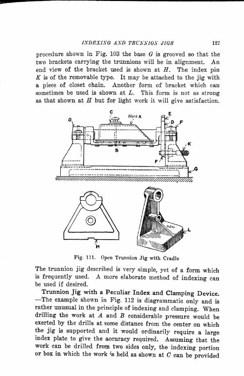
INDEXING AND TRUNNION JIGS 127
procedure shown in Fig. 103 the base G is grooved so that the
two brackets carrying the trunnions will be in alignment. Anend view of the bracket used is shown at H. The index pinK is of the removable type. It may be attached to the jig with
a piece of closet chain. Another form of bracket which can
sometimes be used is shown at L. This form is not as strong
as that shown at H but for light work it will give satisfaction.
w^%^^^
Fig. 111. Open Trunnion Jig with Cradle
The trunnion jig described is very simple, yet of a form whichis frequently used. A more elaborate method of indexing canbe used if desired.
Trunnion Jig with a Peculiar Index and Clamping Device.The example shown in Fig. 112 is diagrammatic only and is
rather unusual in the principle of indexing and clamping. Whendrilling the work at A and B considerable pressure would beexerted by the drills at some distance from the center on whichthe jig is supported and it would ordinarily require a largeindex plate to give the accuracy required. Assuming that thework can be drilled from two sides only, the indexing portionor box in which the work is held as shown at C can be provided
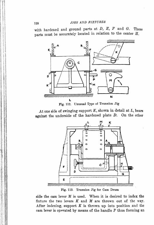
128 JIGS AXD FIXTURES
with hardened and ground parts at D, E, F and G. These
parts must be accurately located in relation to the center H,
W%%%%%2^^ N
Fig. 112. Unusual Type of Trunnion Jig
At one side of swinging support K, shown in detail at L, bears
against the underside of the hardened plate D. On the other
w/////////////////m^^
Fig. 113. Trunnion Jig for Cam Drum
side the cam lever M is used. When it is desired to index the
fixture the two levers K and M are thrown out of the way.
After indexing, support K is thrown up into position and the
cam lever is operated by means of the handle P thus forming an

INDEXING AND TRUNNION JIGS
accurate index and locking the entire mechanism securely. The
supporting latches and cams must be of sufficient size to give the
necessary stability to the structure.
An example of a good trunnion jig for a large cast-iron drumwhich has a series of holes half way around the outside is shownin Pig. 113. The work is located by means of the finished hubs
A and B, which rest in bearings as shown and are clamped bymeans of hinges and leaf clamps. The work is located sidewise
VY
Fig. 114. Trunnion Jig Requiring a Sliding Movement when Indexing
by being forced against the stop C by the thumbscrew D.
The index part of this jig is in the form of a cradle. Thebase of the casting E supports the trunnion brackets F and G,in the latter of which the index pin H is located. A connecting
plate K carries the two bushings L and M. In locating the workin the jig the cradle is revolved about 45 deg. from the position
shown which permits the work to be rolled into position without
difficulty.
Trunnion Jigs Requiring a Sliding Movement when Index-
ing. Fig. 114 illustrates the trouble which may be caused by
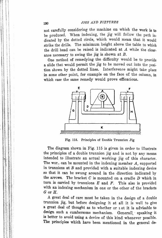
130 JIGS AND FIXTURES
not carefully considering the machine on which the work is to
be produced. When indexing, the jig will follow the path in-
dicated by the dotted circle, which would mean that it would
strike the drills. The minimum height above the table to which
the drill head can be raised is indicated at A while the clear-
ance necessary to swing the jig is shown at B.
One method of remedying the difficulty would be to provide
a slide that would permit the jig to be moved out into the posi-
tion shown by the dotted lines. Interference might take place
in some other point, for example on the face of the column, in
which case the same remedy would prove efficacious.
///r///////^^^
Fig. 115. Principles of Double Trunnion Jig
The diagram shown in Fig. 115 is given in order to illustrate
the principles of a double trunnion jig and is not by any means
intended to illustrate an actual working jig of this character.
The wor~ can be mounted in the indexing member A, supportedin trunnions at B and provided with a suitable indexing device
so that it can be swung around in the direction indicated bythe arrows. The bracket C is mounted on a cradle D which in
turn is carried by trunnions E and F. This also is providedwith an indexing mechanism in one or the other of the brackets
6 or H.
A great deal of care must be taken in the design of a double
trunnion jig, but before designing it at all it is well to givea great deal of thought as to whether or i ot it is advisable to
design such a cumbersome mechanism. Generall. speaking it
is better to avoid using a device of this kind whenever possible.The principles which have been mentioned in the general de-

INDEXING AND TRUNNION JIGS 131
serlptlon of trunnion jigs can be applied with, equal favor to
the double trunnion type, but it must be remembered that there
are movements in each direction to take care of, and there is
considerable danger of interference when indexing from one
position to another. However, there are a number of double
trunnion jigs in use here and there throughout the countrywhich have given satisfaction.
Fig. 116. Example of a Difficult Drilling Problem
A Difficult Drilling Problem. The work shown at A in Fig.
116 is a gasoline tank filler flange which must be drilled with
eight %6-in. holes E. The second view indicates the accuracy
required. It is suggested that the tool designer use this examplefor practice and design a trunnion, cradle or indexing jig in
which the various holes can be drilled.
It is a difficult piece of work to handle efficiently and it will
serve as a very good brain stimulus to the tool designer. Heshould be able after a review of the various points and exam-
ples given under indexing and trunnion jigs to design a
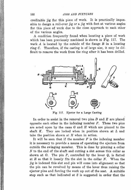
132 JIGS AND FIXTURES
creditable jig for this piece of work. It is practically impos-
sible to design a roll-over jig or a jig with, feet at various angles
for this piece of work due to the close approach to each other
of the various angles.
A condition frequently found when locating a piece of work
which has been previously machined is shown in Fig. 117. The
work A is located by the outside of the flange B in a locating
ring C. Therefore, if the casting is of large size, it may be dif-
ficult to remove the work from the ring after it has been drilled.
"Fig. 117. Ejector for a Large Casting
In order to assist in the removal two pins D and E are placed
opposite each other in the indexing member F. These two pins
are acted upon by the cams G and H which are pinned to the
shaft K. They are locked when in position shown at L and
take the position shown at M when in action.
It will be seen that if the member F is the indexing memberit is necessary to provide a means of operating the ejectors from
outside the swinging member. This is done by pinning a collar
N to the end of the shaft and cutting a slot across this collar as
shown at 0. The pin P, controlled by the lever Q, is flatted
at E so that it loosely fits the slot in the collar N. When the
jig is indexed this slot and pin will come into alignment so that
the pin can be revolved by means of the lever thus raising the
ejector pins and forcing the work up out of the seat. A suitable
stop such as that indicated at 8 is suggested in order that the

INDEXING- AND TRUNNION JIG8 133
lever may always regain a certain position to make the engage-
ment of the pin with the slot absolute.
Trunnion Jig Used Progressively. Let us assume that a
piece of work, held in the trunnion jig at A in Fig. 118, is to
be drilled from three sides in sequence. It is possible to mount
the trunnion jig on wheels and to provide a track on which the
jig can be rolled, so that it will come successively under the
T///7/////////WW
Operation 3 Operation 1 Operation I
Fig. 118. Trunnion Jig Used Progressively
spindles of the three single spindle machines equipped with mul-
tiple heads. It may be found advisable to provide suitable stops
for the positions of the jigs. Arrangements of this kind would
be made only when high production was desired.
The use of the trunnion jig for progressive machining is verycommon in the modern automobile shop, however, for drilling
cylinder and crankcase castings. Frequently as many as half
a dozen different operations are performed on as many ma-
chines, the jig passing along the track from one machine to the
next as the successive operations are performed.

CHAPTER VI
DETAILS OF MILLING FIXTURE CONSTRUCTION
TYPES OF MILLING MACHINES TYPES OF CUTTKIIS IMPORTANT
DETAILS IN FIXTURE CONSTRUCTION ELIMINATION OF LOST
TIME ELEMENTS NECESSARY IN EFFICIENT TOOL DESIGNING
LOCATING POINTS METHODS OF (CLAMPING APPLICATIONS
OF THE LEVER' MULTIPLE CLAMPS DESIGN AND USE OF THE
HOOK-BOLT SUPPORTING AND CLAMPING THIN CASTINGS- -
PRINCIPLES AND METHODS OF PNEUMATIC CLAMPING.
As a factor in high production of interchangeable parts, the
milling machine is of the greatest importance. With the excep-
tion of the turret lathe and screw machine there IN no other
machine tool which approaches it in importance to manufactur-
ing. On account of its value as a producer, the fixtures used
in connection with it should be of the most up-to-date character
and should be so designed as to obtain the greatest efficiency
from the machines to which they are applied,
Types of Milling Machines. In order to understand thor-
oughly the requirements of milling fixtures, it. is necessary first
to know the various types of milling machines in order that
their adaptability for different classes of work may be fully
appreciated. There are a number of forms of machines* amongwhich are hand-milling machines, Lincoln type, plain and
universal, duplex, multiple spindle, vertical, continuous and
some other varieties more or less specialized either in generalmode of operation or in their application to particular kinds of
work. Among the latter class are spline milling, profiling, cam
cutting, automatic form-milling, rack cutting gear cutting and
bobbing machines. There is also the thread milling machine
for milling screw threads and worms. In fact, the process of
milling is adapted to so many kinds of work that new machines,134
DK'rA/l.ti OF MIUJNO PlXTVJtK CONSTRUCTfON 135
which employ milling- as a means for removing stock, are eon-
tinually being- developed to assist in the solution of production
problems.Considered as a, machine type, there are more varieties of
milling machines on the market than any other machine tool in
use to-day. The engine lathe IB frequently used in small shopsas a milling machine and many horizontal boring mills are
arranged so that they can be used for milling as well as for
boring. In reality, any machine having a spindle to which a
milling cutter can be applied has possibilities in the line of
milling, and can be adapted to this kind of work by the use of
a sliding fixture arranged to operate at right angles to the
spindle.
However, we shall take up the application of milling fixtures
to only those types of milling machines that are commonly used
for product ion.
Selection of Machines. The efficiency of a milling fixture
may often be affected by the type of machine on which it is
used. Hence it is well to consider the adaptability of the vari-
ous machines used in milling operations in order that a judicious
selection may be made for a given piece of work. In order to
fam ilinrao the 1 designer with the adaptability of the various
types of milling machines a series of diagrams Is given here-
with* a reference to which will be of assistance in reaching a
decision,
These* diagrams are intended to show the particular class of
work for which the machines are beat adapted, yet it must be
remembered that there in no hard and fast rule, which will abso-
lutely determine the* placing of a certain kind of work on a given
type of machine, Many factors have an influence in the mat-
ter; for example, a form milling operation may be most suited
to it Lincoln type of milling machine, yet on occasion it may be
accomplished Hatlsfactorily on a plain milling- machine if the
Lincoln type machine In not available. So also a key-way maybe cut on a hand milling
1 machine or on a plain machine, and
a Htraddlo milling operation may be clone on a hand milling
machine. In the wleetion of machines, then, the designer must
b governed not only by each machine's adaptability to the work
in quwtion but ttlc> by the machines which are available. In
an old factory thi8 matter must be carefully considered, as the

136 JIGS AND FIXTURES
machines are already installed, but in planning operations for
a new factory, where new machinery is to be bought, it is im-
//g Ma
Fig. 119. Type of Bench Milling Machine
portant to select the machine most suited to the work and pur-
chase it.
/ Tape/ r
Longitudinal Travelof Tabte is 4"
Fig. 120. Another Type of Bench Milling Machine
Bench Milling Machines. A type of bench milling machine
which is very useful for small work is shown in Pig. 119. Ma-
chines of this kind are often made and used for production work

IWTAIl.ti OF MILLING P/XTUKK CONSTRUCTION 137
various kinds, and their accuracy and compactness make them
ry useful when groat numbers of small parts are to be milled,
10 eoiustruetion of the machine will he clearly understood fromi* illustration.
Another type of bench milling1 machine is shown in Fig. 120.
10 arrangement of this is slightly different from the one previ-
sly described, but it serves to show the field of such machines.
10 feeding mechanism in this case is by means of a hand lever
hieh operates a sector meshing with a rack on the under side
the dovetail slide. Fixtures can be applied to the table,
hieh is provided with a T-slot for convenience.
Hand Milling Machines. Referring to the diagram at A in
ig. 121, two views of a standard type of hand milling machine
e shown. Machines of this kind can usually be purchased in
vo sizes, both of which are driven by an open bolt without back
wiring. They are usually provided with a two- or three-step
we pulley in order to obtain a suitable range* of speeds. In
>mo types the head II which carries the spindle is mounted on
vertical slide, HO arranged that it can he moved up or down
y means of the lover (\ to which a weight /) is often attached
;i order to provide a gravity food. The table E has a cross
lovemenf operated by a lever. An over-arm F is arranged HO
hut the arbor can he given an outboard support when desired.
Vnothor type* of hand milling machine has a spindle mounted
n n fixed head, the table being arranged so that it can be fed
ip and down by one lever and crosswise by another. This type
s not hown in the diagram, but its construction will be readily
uidorHtom!.
The eliwH of work to which those machines are most suited
ww'wts of key-wiiy cutting, slotting, light-facing or forming
:-ut % ligbt strmldlo milling operations, or any other light work
f it similar ohnruotor. The machine, not being equipped with
hack geiitx in not nulled for any kind of heavy cutting nor is it
adaptable to long surface cuts on account of its being a hand
feed marbine. For work on brans or aluminum parts, which
require high surface Bpeedn, thus type of machine is a wonderful
producer, rapid in operation and economical in upkeep. It is
frequently utilised for light facing cuts by using an end mill.
Plain Milling Machines. The diagram at (I shows a plain
milling nmohim* whieh m made, in a number of sixes suitable

138 JIGS AND FIXTURES
for both light and heavy work. The smaller sizes are sometimesmade without back gears while the larger machines are heavilygeared and suitable for very heavy cutting. The same general
type of machine, when adapted to very heavy cutting, is vari-
ously termed a"manufacturing milling machine" or a "heavy-
duty milling machine," according to the manufacturer's fancy.In this type of machine the spindle H is tapered at the end
YttJb/e
Fig. 121. Hand and Plain Milling Machine Diagrams
to receive the arbor K, and oftentimes a cross slot in the end of
the spindle is provided to give additional driving power to the
cutter arbor. The over-arm L is adjustable so that it will sup-
port the end of the cutter arbor as indicated. Additional arbor
supports can be used midway on the over-arm to give additional
rigidity for very heavy cutting. The table on machines of this
type is arranged so that it has three movements:
1. Adjustment or power feed in and out in the direction in-
dicated by the arrows M.
2. Hand and power feed at right angles to the cutter arbor.

DKTA/l.N OF MllJ.lXtl FIXTURK VONtiTkUCTION 139
;L Hand aiul sometimes power feed vertically hi the direction
of the arrows at A".
The table () is provided with two or more T-slots used for
locating fixtures and clamping work.
Machines of this type are used for slotting, straddle milling,
face milling, gang milling, form milling, etc. The larger sizes
r, "7?^7,m?fflffiCufter
Fig, liS'Jt, Unc'uhi Typt* and Duplex Milling Machine Diagrams
are chiefly used in mtmufacturing in connection with milling
fixture* for heavy cutting, and can be adapted for many kinds
of work, Tin 1 over-arm can lie dispensed with for work when
an end mill IK nwul like that nhown at V. Also a large inserted
tooth mill can ho applied to face a piece of work as at Q.
Lincoln Type of Milling Machine. One of the oldest forms
of millmK mwhiwH in the Lincoln type, a diagram of which is
nhown in Fig. 12*2. Thin machine is quite different from the

140 JIGS AND FIXTURES
others mentioned, as the table has no vertical adjustment. Anadjustment to the spindle permits this to be set vertically within
certain limits. Referring to the illustration, the cutter arbor Ais held by a taper in the end of the spindle B and is drawn back
tightly by means of a threaded rod passing through to the other
end of the spindle. The cutters must be set in relation to the
work by means of spacing collars on the cutter arbor A except
when the table has longitudinal adjustment. Machines of this
kind are built in several sizes, all of which are provided with
back gears and power feed. They are intended principally for
forming cuts, gang milling, heavy straddle milling and slotting.
Their general construction adapts them for use on long work of
such a character that the cut is continuous from start to finish.
Vises with special jaws are frequently used on machines of this
kind for military rifle parts, sewing machine parts and manyother conditions requiring continuous and formed cuts.
Duplex Milling Machine. In general manufacturing it is
often necessary to face off two or more surfaces on opposite sides
of a casting or forging. For conditions of this kind the duplex
milling machine, a diagram of which is shown at C in Fig. 122,
is of great value. Machines of this type are provided with two
spindles, D and E, which are adjustable towards each other and
sometimes vertically. Provision is made for heavy cutting bymeans of back gears in some types, while others are driven byan open belt on a two- or three-step cone pulley. The machines
are made in several sizes for both light and heavy work.
The class of work to which machines of this kind are best
adapted is shown by the work F in the illustration, but in the
smaller sizes they are useful for slotting or facing bosses on oppo-
site sides of light castings and other work of a similar nature.
Many cases are encountered when work can be done by their
assistance which would require two operations on some other
type of machine.
Vertical Milling Machines. Machines having a vertical spin-
dle, adapted to hold milling cutters, are made in several sizes
by a number of manufacturers. We are not particularly inter-
ested in the various types, as these are much the same in gen-
eral construction, although some have more refinements and con-
veniences than others. Generally speaking, the spindle is driven

N OF Mll.LlXU FIXTURK CONSTRUCTION 141
by means of gearing except in the machines intended for verylight work, la some types an accurate vertical adjustment to
the spindle with a convenient method of setting makes it pos-sible to mill .several heights of work one after the other without
disturbing the height of the table during- the process. By the
use of size blorks and the adjustment mentioned very accurate
work can he produced in this way.
Fig. 12:! shown a diagram of a vertical nulling machine at A,
Cutter.
Fig, llJtt. Wrtlrtd, C'ntttimiouH arid Multi Hpimllo Milling Machines
with n largo uwrrted tooth cutter It, in use for surfacing the
work ('. The* tithie /> is provided with power longitudinal feed
and occasionally with power cross and vertical feeds also. Ma-
chines an* arranged to give it variety of feeds in both directions
on mte imtchimH, while in others the longitudinal feed to the
table is the only one. Adjustments are always provided, how-
ever, for rawing and lowering the table and moving it in and
out. The tonjdtucUnal feed is the most used, although the others
are occasionally required and are very useful at times.
The work to which thene tools are best adapted is the facing
of large ciwtingH, such a flange's, transmission cases, etc., al-
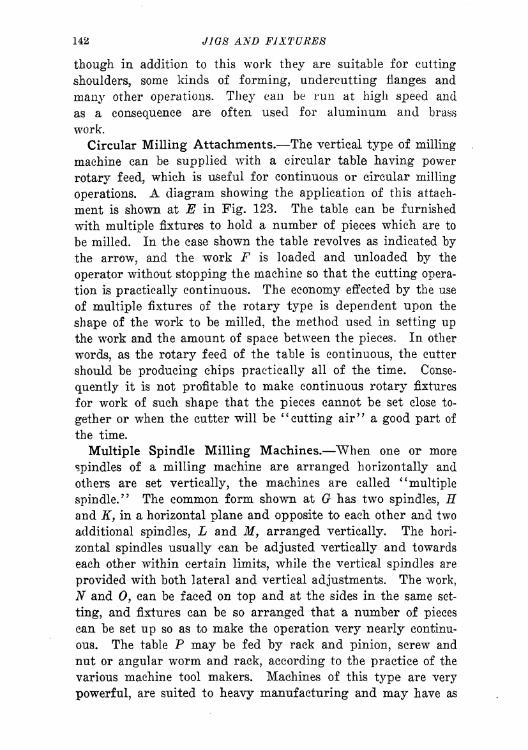
142 JIQS AND FIXTURES
though in addition to this work they are suitable for cutting
shoulders, some kinds of forming, undercutting flanges and
many other operations. They can be run at high speed and
as a consequence are often used for aluminum and brass
work.
Circular Milling Attachments. The vertical type of milling
machine can be supplied with a circular table having power
rotary feed, which is useful for continuous or circular milling
operations. A diagram showing the application of this attach-
ment is shown at E in Fig. 123. The table can be furnished
with multiple fixtures to hold a number of pieces which are to
be milled. In the case shown the table revolves as indicated by
the arrow, and the work F is loaded and unloaded by the
operator without stopping the machine so that the cutting opera-
tion is practically continuous. The economy effected by the use
of multiple fixtures of the rotary type is dependent upon the
shape of the work to be milled, the method used in setting upthe work and the amount of space between the pieces. In other
words, as the rotary feed of the table is continuous, the cutter
should be producing chips practically all of the time. Conse-
quently it is not profitable to make continuous rotary fixtures
for work of such shape that the pieces cannot be set close to-
gether or when the cutter will be "cutting air" a good part of
the time.
Multiple Spindle Milling Machines. When one or more
spindles of a milling machine are arranged horizontally and
others are set vertically, the machines are called "multiple
spindle." The common form shown at G has two spindles, Eand K, in a horizontal plane and opposite to each other and two
additional spindles, L and M, arranged vertically. The hori-
zontal spindles usually can be adjusted vertically and towards
each other within certain limits, while the vertical spindles are
provided with both lateral and vertical adjustments. The work,
N and 0, can be faced on top and at the sides in the same set-
ting, and fixtures can be so arranged that a number of pieces
can be set up so as to make the operation very nearly continu-
ous. The table P may be fed by rack and pinion, screw and
nut or angular worm and rack, according to the practice of the
various machine tool makers. Machines of this type are very
powerful, are suited to heavy manufacturing and may have as
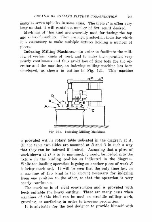
DETAIL** OF MILLING FIXTURK CONSTRUCTION 143
many as seven spindles in some eases. The table P is often very
long so that it will contain a number of fixtures if desired.
Machines of this kind are generally used for facing the topand sides of castings. They are high production tools for which
it is customary to make multiple fixtures holding a number of
pieces.
Indexing Milling Machines. In order to facilitate the mill-
ing of certain kinds of work and to make the operation very
nearly continuous and thus avoid loss of time both for the op-
erator and the machine, an indexing milling machine has been
developed, as shown in outline in Fig. 124. This machine
^
Fig, 124. Indexing Milling Machines
fa provided with a rotary table indicated in the diagram at A.
On the table two slides are mounted at B and C in such a waythat they can be indexed if desired. Assuming that a piece of
work shown at /> is to be machined, it would be loaded into the
fixture* in the loading position as indicated in the diagram.
While the loading operation is going on another piece of work Kin being
1 machined. It will be seen that the only time lost on
a machine of this kind is the amount necessary for indexing
from otii* pomtion to the other, so that the operation is very
nearly continuous.
The machine is of rigid construction and is provided with
feeds suitable for heavy cutting. There are many eases when
machines of this kind can be used on straddle milling work,
grooving, or surfacing in order to increase production.
It is advisable for the tool designer to provide himself with

144 JIGS AND FIXTURES
data showing various dimensions of importance on milling ma-
chines. These diagrams can be made up in a form like that
shown in Fig. 125. There is practically all the information
given that the tool designer needs when designing a milling fix-
ture for use on this particular type of machine. It is not neces-
Fig. 125.
Oreraff LengthWorking Length of 7ab/e-<
LongitadfnaJ Feedof Table-471%
Diagram of Milling Machine Showing Dimensions
Necessary for Designing Fixtures
sary to make diagrams of this kind in great detail, but maximumand minimum dimensions are important, as they show the rangeof the machine. Dimensions of T-slots and spacing of the same
together with table dimensions are important.Selection of Milling Cutters. Various kinds of work require
cutters of different kinds in order to produce the work to the
best advantage. In the selection of these cutters the tool engi<-

1>KTA/LN OF MILLING FIXTURE CONSTRUCTION 145
neer must be governed by the kind of material which is to be
cut as well as the* form of the cut. Fig. 126 shows a numberof milling operations with the cutters most suitable for each par-
ticular piece of work. The work A is made from steel, and it is
sfl
*.'
L
Fig, lii. Application of Milling Cutters
to bet HurfamL AHHumitig it to bo a forging, a spiral cutter
like that nhown t K would le suitable, for the work. This cutter
would him* tlu* variotw teeth nicked alternately in order to
4
*brcak the chip*1
if the cut were to be a very heavy one.
This work (J m of <*at.-iron arid is to be slotted at D. For work
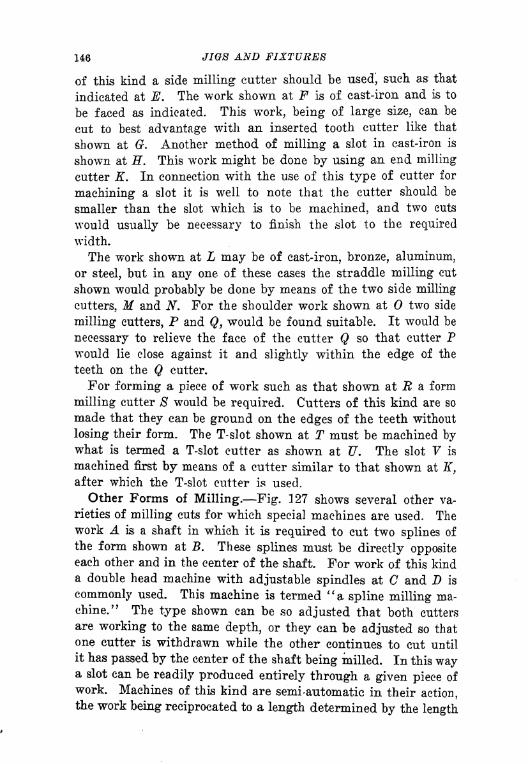
146 JIGS AND FIXTURES
of this kind a side milling cutter should be used, such as that
indicated at E. The work shown at F is of cast-iron and is to
be faced as indicated. This work, being of large size, can be
cut to best advantage with an. inserted tooth cutter like that
shown at G. Another method of milling a slot in cast-iron is
shown at H. This work might be done by using an end milling
cutter K. In connection with the use of this type of cutter for
machining a slot it is well to note that the cutter should be
smaller than the slot which is to be machined, and two cuts
would usually be necessary to finish the slot to the required
width.
The work shown at L may be of cast-iron, bronze, aluminum,
or steel, but in any one of these cases the straddle milling cut
shown would probably be done by means of the two side milling
cutters, M and N. For the shoulder work shown at two side
milling cutters, P and Q, would be found suitable. It would be
necessary to relieve the face of the cutter Q so that cutter Pwould lie close against it and slightly within the edge of the
teeth on the Q cutter.
For forming a piece of work such as that shown at R a form
milling cutter 8 would be required. Cutters of this kind are so
made that they can be ground on the edges of the teeth without
losing their form. The T-slot shown at T must be machined bywhat is termed a T-slot cutter as shown at U. The slot V is
machined first by means of a cutter similar to that shown at If,
after which the T-slot cutter is used.
Other Forms of Milling. Fig. 127 shows several other va-
rieties of milling cuts for which special machines are used. Thework A is a shaft in which it is required to cut two splines of
the form shown at B. These splines must be directly oppositeeach other and in the center of the shaft. For work of this kinda double head machine with adjustable spindles at C and D is
commonly used. This machine is termed "a spline milling ma,-
ehine." The type shown can be so adjusted that both cutters
are working to the same depth, or they can be adjusted so that
one cutter is withdrawn while the other continues to cut until
it has passed by the center of the shaft being milled. In this waya slot can be readily produced entirely through a given piece of
work. Machines of this kind are semi-automatic in their action,the work being reciprocated to a length determined by the length
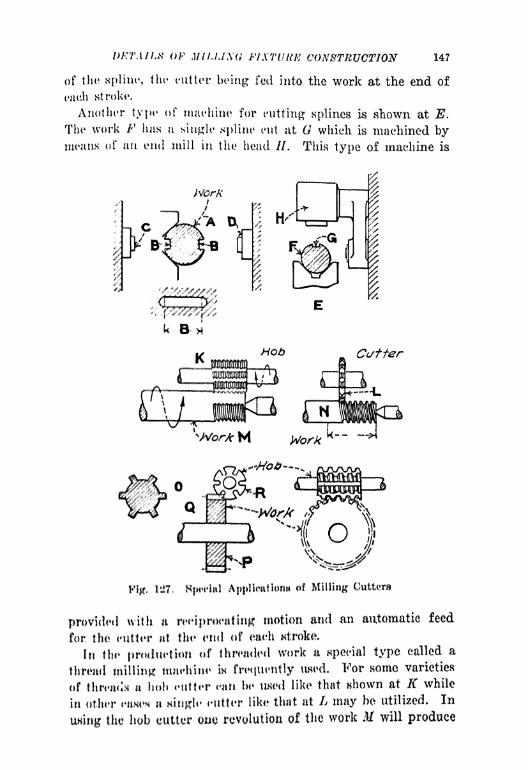
IWTMI.N Of Mll.MXd FIXTURE CONSTRUCTION 147
of the spline, the cutter he ing fed into the work at the end of
each stroke.
Another type of machine for cutting splines is shown at E.
The work F has a single spline cut at which is machined bymeans of an end mill in the head //. This type of machine is
x
k~B~
Fig, 1*27, Application* of Milling Cutters
provided with a iwi profitting motion and an automatic feed
for the Hitter at the end of eah stroke,
In the prndut'tum of thwaded work a special type called a
thread milling miifhine w frequently iwod. 'For some varieties
of titrc*a(!M a holt <titter can he HKCH! like that shown at K while
in other ^nmm a single cuttor like that at L may he utilized* In
using the hob cutler cue revolution of the work M will produce

148 JIGS AND FIXTURES
a completed piece. In the other case the work ATwould need to
be revolved as many times as there are threads.
For very heavy Acme or square threads the thread milling
machine is very useful, and it is utilized also for threading shafts
such as lead screws. The work obtained by this method is very
accurate and uniform in quality.
Spur and spiral gears are often cut on gear cutting machines
or gear hobbing machines. Splined shafts like that shown in
Fig. 128. Contour Cutter Sizing Chart with Teeth Set Off 6 Degrees
the section at are also made on a hobbing machine of this type.
The work P, which is a spur gear, would be mounted on an arbor
Q in a gear hobbing machine, and the teeth would be cut bymeans of a hob as indicated at R. In operation the gear is con-
tinually revolving, and the hob cutter gradually passes throughone or more gears according to the size and general shape of
the blanks. Suitable feeds are provided, and the machine is also
furnished with a knock-off which can be set so that the machine
will be stopped after the work is finished.
There are many other milling machines of more or less spe-
cialized forms, some of which are used in the manufacturing of

DETAILS OF MILLING FIXTURE CONSTRUCTION 149
certain kinds of work. As these machines are so highly spe-
cialized, it is not advisable to attempt a description of them be-
cause they are seldom required by the tool engineer when work-
ing out production problems.
Fig. 129. Inserted Tooth Milling Cutter with Staggered Blades
Cutter Sizing Chart. A contour cutter sizing chart is shown
in Fig. 128. This chart is convenient for use in designing mill-
ing cutters. The number of teeth varies according to the diam-
eter of the cutter, and in this example all teeth are set off 6
deg. Variations can be made to suit conditions, but the chart in
itself will be found useful as a guide in obtaining properly pro-
portioned cutters.

150 JIGS AND FIXTURES
Fig. 129 shows a chart for inserted tooth milling cutters hav-
ing staggered blades. In this example the blades are set over
alternately as indicated. This makes it useful in sizing a slot
or something of this sort. The various dimensions given will
be found useful in proportioning cutters of this kind.
OiajrfWer Ho-ofTeeUt &
IG 5k ToSuif .3/4
18 Vk ToSuit ? 7/8
?0 ToSuit 3% .418
8% ToSuit .470 3/43/8
10 ?4 ToSuit .523 J!/i_26 To Suit 4% .575 7
/l6
1? Zd ToSuit .627
Fig. 130. Inserted Tooth Milling Cutter with Solid Body
Fig. 130 shows another type of inserted tooth milling cutter
made with a solid body as shown. This type of cutter is de-
signed primarily for face milling, and the body screws directly
on to the spindle. The proportions and various dimensions
given will be found useful in proportioning cutters of this kind.
Fig. 131 shows a chart of straight side inserted tooth milling
cutters. This type of cutter is designed for use on an arbor.
Fig. 132 shows another type of inserted tooth cutter designed

DETAILS OF MILLING FIXTURE CONSTRUCTION 151
for face milling. This can be made up in solid form as shown
and applied to the spindle in some convenient manner. The
blades are set at an angle in this example.
Important Points in Design of Milling Fixtures. In the
D/a.
Dia.ofPfns
14 .136 Ityie .261
16 5 l
/2 .JQ9 2% ,314
18 .210 2 7/8 .366
20 .262 3% 418
22 .3/4 .470
10 24 9% .335 .523 /'/* 7/6
26 10% .388 .675
12 29 11% .440 .27
Fig. 131. Standard Straight Side Inserted Tooth Milling Cutters
design and construction of milling fixtures, the following points
should be carefully considered:
1. Production Required. This is an important factor, as the
number of pieces to be machined should influence the design of
the fixture to a great extent. Simple fixtures should be madefor work which is machined only in small quantities, while for
high production work the best type of fixture should be de-
signed.

152 JIGS AND FIXTURES
2. Dead Tim 3 on the Machine. In analyzing a production
problem in which the milling machine is to be used, the dead time
on the milling machine should be reduced to a minimum in order
to obtain the maximum efficiency of the machine. The milling
fixtures should be so designed that there is as little time lost as
possible during the loading and unloading of the fixture. In
very high production work it is frequently desirable to make up
i Fig. 132. Standard Inserted Tooth Face Mills
fixtures that permit one piece of work to be inserted and clampedwhile the other is being machined.
3. Accuracy Required. When work is to be milled within a
tolerance of 0.001 in., it is frequently necessary to make provi-
sion for both roughing and finishing cuts. As a rule two fixtures
should be made for work of this kind, each one being providedwith suitable set blocks for setting the cutters to the required
sizes.
4. Rigidity of Fixtures. There is no operation in manufac-
turing in which rigidity is as important as in milling. Weak-

DETAILS OF MILLING FIXTURE CONSTRUCTION 153
ness tends to develop "chatter," which is injurious both to the
cutters and to the machine. Care must be taken in the designof milling fixtures to make sure that there are no weak pointsand that all portions are well ribbed to withstand cutting strains.
5. Safety of the Operator. The importance of designing
milling fixtures so that the operator will not be endangered
during the process of loading and unloading the work cannot
be over-emphasized. The operator's hands should not approachthe cutters closely. The position which the operator is requiredto take when using the fixture must be studied so that there is
no chance for injury due to lack of attention.
6. Chips. As the milling machine is a great producer of
chips, attention should be paid to the cleaning of the fixture,
and clamps, locating surfaces, and other important parts should
be so designed that chips will not interfere with their proper
functioning.
7. Set Blocks. All milling fixtures should be provided with
set blocks so arranged that the cutters can be set in correct re-
lation to the work. A size block or "feeler" can be interposed
between the cutter and the set block when making adjustments.
If all fixtures for milling are provided with set blocks the ac-
curacy of the work is assured, and resetting after grinding the
cutters is very easily done.
8. Selection of Machines. The selection of the machine best
suited to work requires judgment, knowledge of conditions, and
a list of machines which may be used, as well as an understand-
ing of the best type of machine for the work in the event that
new tools are be purchased. Although the choice of machines
may be limited, the selection should always be made with a view
to economy in production.
,9. Upkeep of Fixtures. Fixtures for high production work
should be so designed that replacement of locating parts, studs,
clamps and other parts can be readily made. It is very neces-
sary to provide a suitable method of fastening the various units
to the fixture in order to facilitate their removal and replace-
ment when worn.
10. Material To Be Cut. The kind of material to be ma-
chined affects the design of the fixture to some extent, due to
the fact that cast-iron or other cast work such as aluminum
and brass can usually be cut faster than such material as alloy

154 JIGS AND FIXTURES
steel. Therefore, the kind of material and the speed and feed at
which the job will run have to be considered in planning mill-
ing fixtures.
Cutter Action on the Work. A piece of work being milled
is subject to two forces, viz., the feed and the cutting action.
The combined result of these two forces tends to move the work
out of its position, hence it must be resisted by the fixture and
the clamps which hold the work. Due consideration must there-
Wrong Right
Fig. 133. Diagrams Illustrating Cutter Action
fore be given to the manner in which the work is held in relation
to the feed and also to the cutter.
Fig. 133 shows a piece of work at A in which a slot B is being
machined. The feed of the table is in the direction of the arrow
C, while the cutter revolves as shown by the arrow D. The
action of the cutter tends to pull the work toward it, which is
very bad practice for the reason that any lost motion in the
feed screw of the table will cause"chatter" in the work; also
the work tends to "crowd" into the cutter teeth so that the
cutting action is not good. "When the work is fed in the same

/<' MILUSU u CONSTRUCTION 155
direction (' with the cutter revolving in the direction F, there
Ls no "chatter" and the teeth of the eutter attack the work in'
the proper manner.
The work (! Is being fed in the direction of the arrow If, while
anWork
\V,
\ X
Fig, 134. Action of Cutter Teeth
the eutter in revolving a.s at K. This is incorrect because the
cutter action tends to lift the work and may therefore be acting
atfttmut the damps which hold it down on the fixture. It mayeven lift the table itaelf unless the gibs are adjusted tightly.
Wrong*R0ht
Fig. Kir. CuUi*r Action in Relation to Clamps
When the* cutter h revolving in the direction M, the pressure?
of th cut in rwite<i hy the* ntability of both the fixture and
the table,
Fife. 1W flhows n IHJJT A which in to be slotted as indicated
at /I. Vnlmn i-iire in imecl in the selection of the cutter, a con-
dition like that rthowii In the cutter C may be found. This eut-
ter has teeth /> ipiiced RO far apart that not more than one tooth
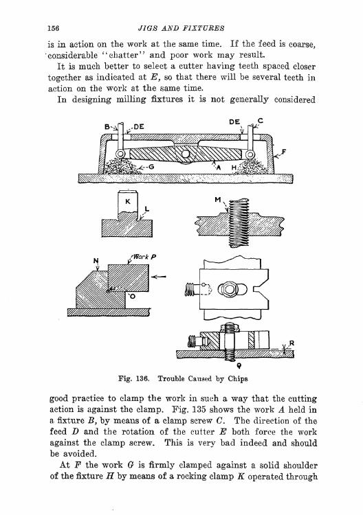
156 JIGS AND FIXTURES
is in action on the work at the same time. If the feed is coarse,
"considerable "chatter" and poor work may result.
It is much better to select a cutter having teeth spaced closer
together as indicated at E, so that there will be several teeth in
action on the work at the same time.
In designing milling fixtures it is not generally considered
DE
Fig. 136. Trouble Caused by Chips
good practice to clamp the work in such a way that the cutting
action is against the clamp. Fig. 135 shows the work A held in
a fixture B, by means of a clamp screw C. The direction of the
feed D and the rotation of the cutter E both force the work
against the clamp screw. This is very bad indeed and should
be avoided.
At F the work (? is firmly clamped against a solid shoulder
of the fixture H by means of a rocking clamp K operated through

Il^ OF MILLING FIXTURE CONSTRUCTION 157
the threaded rod L. The thrust of the cut is then taken by asolid wall of metal and there is no possibility of "chatter."
Provision for Chips. Milling' cutters produce chips very
rapidly and in largo quantities. Therefore milling fixtures
should be designed so that locating surfaces, clamps, screws andother devices will not become elogged with chips so as to inter-
fere with their proper working. Fig. 136 shows an equalizinglever A, eonneeted to two rods K and C which pass through the
holes /> and K in the body of the milling fixture F. The open-
ings around the rods 'permit chips to fall through and accumu-
late at <) and //, resulting eventually in interference with the
action of the* levers. The holes should be covered in order to
prevent this accumulation or else the fixture should be arrangedo that it can be readily cleaned. As a milling
1 fixture is alwaysbolted down to the 1 table in a fixed position, provision for clean-
ing should not necessitate 4 its removal from the table. Openingsin the side of the* fixture can be made but it is better to preventthe chips from entering and thus do away with the necessity
for cleaning.
At K i shown a locating stud with a groove at / into which
chips or dirt may drop so that work located on the plug will
seal itself properly. This is very bad indeed as after a time
the groove fills up with chips and dirt which have to be cleaned
out frequently to allow the work to locate properly. M is an
adjustable, threaded member in a fixture base. This also should
be avoided as far IIH possible because chips will eventually work
into the thread and make it difficult to operate.
The locating block N is relieved at in order to ensure cor-
rect location of the work /*. This design is open to the same
object ions an the example K.
The type of adjustable V-block shown at Q is most annoyingto an operator, as the chips get in to the elongated slot and also
under the block causing it to rise us shown at R.
Design of Milling Fixtures. There is some difference of
opinion as to whether a well-ribbed milling fixture will give as
satisfactory results as OIK* which is made of very heavy section
cant iron without ribbing. Those advocating heavy sections
without ribbing claim that the solidity of the metal in a heavy
milling fixture tends to lemen vibration and thus give better
results than a ribbed milling fixture. The writers believe that

158 JIGS AND FIXTURES
a well-ribbed milling fixture of substantial section will answer
the purpose in nearly all eases although for extremely heavycuts a good body of metal is desirable.
Fig. 137 shows at A a solid base plate of cast iron on which
a built up fixture can be placed. The illustration B shows a
similar, though heavier plate. The latter would be better de-
signed as shown at C, with the mass of metal reduced and the
sections strengthened by the use of ribbing. The view at Dindicates the position of the various ribs. The ribs of a fixture
!
Fig. 137. Design of Fixture Bases
of this type should be so proportioned that there will be no
tendency to "buckle" and thus cause vibration while a cut is
in progress.
Details of Construction. Fig. 138 shows a corner wall Awhich has been made to a large radius in order to give maximum
strength. Square corners on castings and sections of unequal
thickness should be avoided. B shows a square corner which is
likely to crack at the points shown, due to strains set up by
unequal cooling in the foundry.
The diagram at C is given in order to emphasize the fact that
all castings should be so designed as to allow for "draft." Draft
is not necessary to the casting, but the pattern has to be tapered

IWTAILK QF MILLING FIXTURE CONSTRUCTION 159
so that lifter the mold is made, the pattern can be removed fromthe sand without injuring the moid. And as the pattern is a
duplicate of the fasting, the necessary draft is included in thedesign of the casting. The amount of draft necessary variesfrom 4 in. to \ in. per foot. It is advisable to show the draft ondeep Hustings as indicated at I) and E.
Where bosses are provided on castings it is well to make themlarger in diameter than appears necessary, in order that the
'
Strength
>jfff
hi
Fig. 1*18, of Construction
location of holes in tin? bcmaen may not be seriously affected byvariations in the canting. Also when bosses are used as bear-
ing^ it is advisable to mako them large enough so that they maybe* bushed for wear as indicated at I<\ There is nothing muchmore annoying to a toolmaker than to find insufficient allowance
for stock on a boss, so that the hole is not central with the boas,
allowing a shouldered stutl to lap over the edge.
Uniformity of Ribs and Walls. In order that the castings
used for fixture* work may bo sulwrtantial and not subject to
cracks due to unequal cooling, uniformity in the sections should
be preserved an far as possible. Fig, 139 shows a section A in
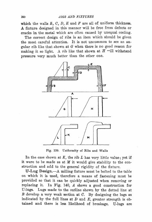
160 JIGS AND FIXTURES
which the walls B, C, D, E and F are all of uniform thickness.
A fixture designed in this manner will be free from, defects or
cracks in the metal which are often caused by unequal cooling.
The correct design of ribs is an item which should be given
the most careful attention. It is not uncommon to see an an-
gular rib like that shown at G when there is no good reason for
making it so light A rib like that shown at H -ill withstand
pressure very much better than the other one.
Fig. 139. Uniformity of Kibs and Walls
In the case shown at K, the rib L has very little value; yet if
it were to be made as at M it would give stability to the con-
struction and add to the general rigidity of the fixture.
U-Lug Design. A milling fixture must be bolted to the table
on which it is used, therefore a means of fastening must be
provided so that it can be quickly adjusted when removing or
replacing it. In Fig. 140, A shows a good construction for
U-lugs. Lugs made to the outline shown by the dotted line at
B develop a very weak section at C. By designing the lugs as
indicated by the full lines at D and E, greater strength is ob-
tained and there is less likelihood of breakage. U-lugs are

DKTAlLti OF MILLING FIXTURE CONSTRUCTION 161
usually cored at F and the cored dimensions should be not less
than ho larger than the T-bolt used to hold the fixture down.
A key slot (t is provided for locating the fixture on the table.
In proportioning the outlines of the boss //, it is well to make
Ing. 140, Il-Lug Doaign
each aide of the finished portion at least one-half the distance Fand even more than this Is not objectionable. The depth Kshould always h from one and one-half to two times the dimen-
sion F.
Fig, 141. T-Blots and Keys
IMugH shoultl not be net in too close to the body of the fixture
HH hulicatccl by the dotted lines at L. It in much better eon-
Htructicin to inako the distance M at leaat as much as the dimen-
Hion F. When this IH clone a large fillet can be used at JV thus
giving additional strength to the fixture.

162 AND FIXTURES
T-Slots and Keys. Milling fixtures are located on the tables
of milling machines by means of rectangular keys which fit the
T-slot A in Fig. 141. A common form of key is shown at B.
The dimension C is made to the size of the slot in the milling
machine table. The length of the key D is generally from 2 to 3
times its width.
As milling machine table slots vary from -} in. to -J in. with in-
termediate sizes, it is often desirable to make fixtures transfera-
Fig. 142. Set Blocks
ble from one machine to another. To provide for such a condi-
tion, the keys can be made as shown in the illustration at E.
This type of key is so proportioned that it can be used to fit a
slot having a width as shown at F and it can also be reversed
and used to fit another slot like that indicated at G. An ar-
rangement of this kind is of great advantage where a number of
milling machines having different size slots are to be used in
production.
Set-blocks. In order to make sure that cutters are set in the
correct relation to the work on a milling fixture, it is essential
that each fixture be provided with suitable set blocks.
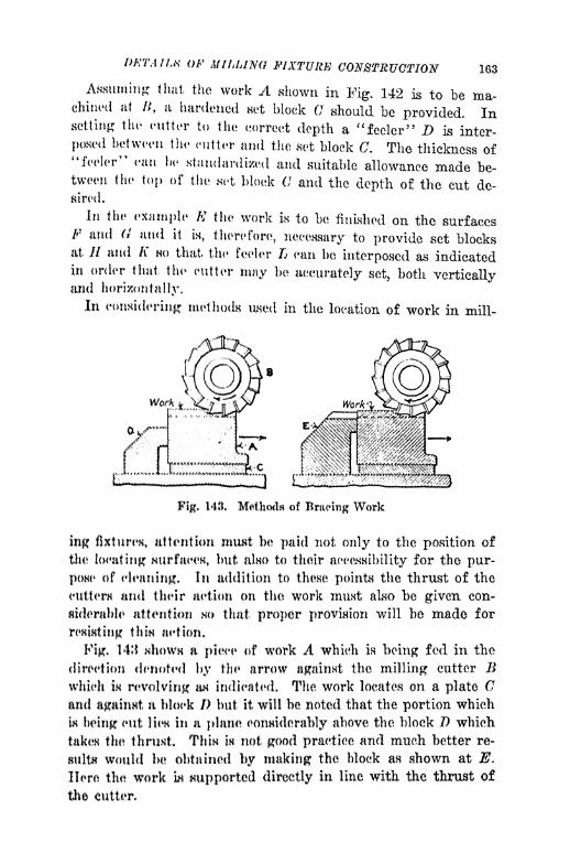
IWTA11.K OF A!UMNO FIXTURE CONSTRUCTION 163
ng that the work A shown in Fig. 142 is to be ma-chined at
,a hardened net block C should be provided. In
setting the cutter to the correct depth a "feeler" D is inter-
posed between the cutter and the set block C. The thickness of"feeler" can lie standardized and suitable allowance made be-tween the top of the set block C and the depth of the cut de-sired.
In the example # the work is to be finished on the surfacesF and (} and it is, therefore, necessary to provide set blocksat // and A" HO that the feeler L ean be interposed *us indicatedin order that the cutter may be accurately set, both verticallyand horizontally.
In considering methods iLsed in the location of work in mill-
Fig. 143. Mftthod* of Bracing Work
ing fixtures attention must be paid not only to the position of
the locating: 8urfae, but also to their accasnibility for the pur-
pOHe of cleaning. In addition to these points the thrust of the
cutterH and their action on the work must also be given con-
siderable attention HO that proper provision will be made for
remitting thm aetion.
Fig. 14! *ihowH a piece of work A which is being fed in the
direction denoted by the arrow against the milling cutter Bwhich IH revolving w indicated. The work locates on a plate Cand against a block I) but it will be noted that the portion which
i being cut lien in a plane considerably above the block D which
takt8 tin* thruHt. Thw IH not good practice and much better re-
sults would be obtained by making the block as shown at E.
Hero the work in supported directly in line with the thrust of
the cutter*
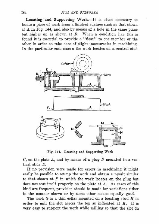
164 JIGS AND FIXTURES
Locating and Supporting Work. It is often necessary to
locate a piece of work from a finished surface such as that shown
at A in Fig. 144, and also by means of a hole in the same plane
but higher up as shown at B. When a condition like this is
found it is essential to provide a "float" to one member or the
other in order to take care of slight inaccuracies in machining.In the particular case shown the work locates on a central stud
^,'
^////////>7//^///fa'-'Work.
Work
Fig. 144. Locating and Supporting Work
C, on the plate A, and by means of a plug D mounted in a ver-
tical slide E.
If no provision were made for errors in machining it might
easily be possible to set up the work and obtain a result similar
to that shown at F in which the work locates on the plug but
does not seat itself properly on the plate at A. As cases of this
kind are frequent, provision should be made for variations either
in the manner shown or by some other means equally good.
The work G is a thin collar mounted on a locating stud H in
order to mill the. slot across the top as indicated at K. It is
very easy to support the work while milling so that the slot on

!.** OF MILLING FIXTURE CONSTRUCTION 165
the side at L will be backed up well, but the opposite side Mwill have a tendency to open up when the cutter machines it,
with a result like that nhowu at N. The designer should always
hear this in mind when making a fixture for a similar piece of
work and .should provide support at the points where the eutter
finishes its work.
Clamps Used in Milling. In the chapter on the design of
drill jigs, various elamps are shown which are used to some ex-
tent in all kinds of fixtures. Exceptional cases may require
slightly different methods of clamping due to the requirements
Fig. 1-15. VarlwiH TypOH of MilliiiK-C
of ihtf work. The method of holding a piece of work for a mill-
ing operation is one of the most important things in connection
with the design of the fixture, and HA a consequence the elamps
nhoutd be very Hulwluntial and should be applied at the proper
pointH in order to obtain the boat reaultH.
Several varietioH of clumps are shown in Fig. 145. The work
A is loeated on a hardened plata B and is clamped down by
meaiiH of thf ntriip dump Bhown at 0. This clamp is slotted
at I> to permit it being withdrawn from the work by means of
the pin K which net* an a handle, A Blotted clamp of this sort
w likely to become* clogged with chips and, therefore, a suitable
cover fihould be placed over the Blot, A braMng V can be made
so that it fills thcs hole ff occupied by the spring Tl thus pre-

166 JIGS AND FIXTURES
venting the chips from accumulating around the spring and
interfering with its action.
The clamp K is used for holding the work down when a clampon the top of the work would interfere with a cutter used on
the entire upper surface. This type of clamp thrusts against
a solid shoulder L and the action of it in clamping tends to sink
the point M into the edge of the work and at the same time hold
it down. It is advisable to make the point M rather"stubby
"
so that it will not become dulled too easily. A clamp of this
kind is useful when it is difficult to clamp the work in the
ordinary way. It is possible to adapt it to a number of condi-
tions to suit particular cases.
A swinging leaf clamp can be used to advantage in holdinga piece of work such as that shown at 0. The work locates on
a hardened plate P and is clamped by means of the screw Qwhich is held in a swinging clamp R. A leaf-type of clamp is
sometimes found necessary in milling fixture design and the
principle shown here can be applied if needed.
A rather peculiar type of clamp for work which cannot be
clamped in the regular way, is shown at 8. This clamp has a
knife-edge at T which sinks into the work and at the same time
clamps it down. The thumbscrew U has a wear plate under the
point as shown at V. It is of the greatest importance in de-
signing a clamp of this sort that the pivot W be located con-
siderably lower than the point T so that the clamping action
will be down in the direction indicated by the radial line X.
Special Forms of Clamps. Work of peculiar or irregular
shape which has not been provided with clamping lugs often
calls for the design of special clamps in order to hold it prop-
erly and without distortion or dislocation. Considerable in-
genuity is sometimes required in order to devise a suitable
method. A number of clamps designed to suit peculiar condi-
tions of holding, are shown in Fig. 146. The casting A has an
overhanging flange C which is to be machined as indicated bythe / mark. The work rests on locating plugs, one of which is
shown at B. The ordinary type of clamp would be difficult of
access if used for a condition of this kind, therefore a device
must be used which will give satisfactory results and which will
be readily accessible. Several methods are shown which may be
adapted to work of this kind.

DETAILS OF MILLING FIXTURE CONSTRUCTION 167
The clamp D is slotted at E to allow it be moved back out
of the way when, placing the work in position, or removing it.
The clamping is accomplished by means of the cam G which is
pivoted to the end of the clamp. The cam bears on the wear
plate F and is operated by the thumbscrew H. This type of
clamp is open to several objections, among which are the cost
of manufacture and its limited range. If the eastings should
vary considerably in thickness at the clamping point the clamp
Fig. 146. Special Forms of Milling-Clamps
might not hold the work at all as the adjustment is somewhat
limited.
Another type of clamp is shown at K for the same piece of
work. In this case a projecting lug is provided on the fixture
at L so that the thumbscrew M can be used to operate the clamp
from beneath. This form can be frequently used on fixtures,
providing the extra depth of fixture needed is not objectionable.
Ample clearance for the operator's knuckles should be provided
when designing this form of clamp.
Another form of sliding clamp is shown at N, for holding the
same piece of work. This type is operated by means of the
sliding wedge which is forced under the end of the clamp by
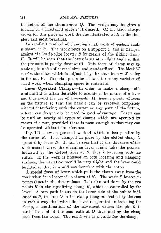
168 JIGS AND FIXTURES
the action of the thumbscrew Q. The wedge may be given a
bearing on a hardened plate P if desired. Of the three clampsshown for this piece of work the one illustrated at K is the sim-
plest and most practical.
An excellent method of clamping small work of certain kinds
is shown at R. The work rests on a support T and is clamped
against the knife-edge locater 8 by means of the sliding clampU. It will be seen that the latter is set at a slight angle so that
the pressure is partly downward. This form of clamp may be
made up in units of several sizes and standardized. The block Wcarries the slide which is adjusted by the thumbscrew X acting
in the nut "P. This clamp can be utilized for many varieties of
small work when clamping space is restricted.
Lever Operated Clamps. In order to make a clamp self-
contained it is often desirable to operate it by means of a lever
and thus avoid the use of a wrench. If there is plenty of room
on the fixture so that the handle can be revolved completely
without interfering with the cutter or any part of the fixture,
a lever can frequently be used to good advantage. Levers can
be used on nearly all types of clamps which are operated bymeans of a nut, provided there is room enough so that they can
be operated without interference.
Fig. 147 shows a piece of work A which is being milled bythe cutter B. It is clamped in place by the slotted clamp C
operated by lever Z>. It can be seen that if the thickness of the
work should vary, the clamping lever might take the position
indicated by the dotted lines at E, thus interfering with the
cutter. If the work is finished on both locating and clamping
surfaces, the variation would be very slight and the lever could
be fitted so that it would not interfere with the cutter.
A special form of lever which pulls the clamp away from the
work when it is loosened is shown at N. The work F locates on
points set in the fixture base. It is clamped down by the two
points K in the equalizing clamp H, which is controlled by the
lever. A cam path is cut on the lower side of the hub as indi-
cated at P, the pin O in the clamp being controlled by the cam
in such a way that when the lever is operated in loosening the
clamp, a continuation of the movement causes the pin to
strike the end of the cam path at Q thus pulling the clampback from the work. The pin L acts as a guide for the clamp.
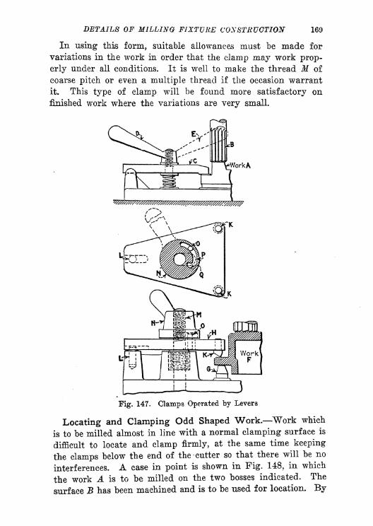
DETAILS OF MILLING FIXTURE CONSTRUCTION 169
In using this form, suitable allowances must be made for
variations in the work in order that the clamp may work prop-
erly under all conditions. It is well to make the thread M of
coarse pitch or even a multiple thread if the occasion warrant
it. This type of clamp will be found more satisfactory on
finished work where the variations are very small.
*WorkA
Fig. 147. Clamps Operated by Levers
Locating and Clamping Odd Shaped Work. Work which
is to be milled almost in line with a normal clamping surface is
difficult to locate and clamp firmly, at the same time keeping
the clamps below the end of the cutter so that there will be no
interferences. A case in point is shown in Pig. 148, in which
the work A is to be milled on the two bosses indicated. The
surface B has been machined and is to be used for location. By

170 JIGS AND FIXTURES
setting it on this surface, on a hardened locating plate in the
fixture C, it can be brought up against the knife-edge locater Dby means of the swinging clamps on the opposite side at F.
The locater D is well backed-up by the lug on the casting at E.
The operation of the swinging clamp F is controlled by the
thumbscrew H so that the knife-edge point forces the piece
over against the locater D and at the same time holds it downon the locating plate B. The pivot K on which the swinging
Work A
Ct R->f
Fig. 148. Locating and Clamping Odd-Shaped Work
clamp moves should always be set well back of the knife-edge
6r, so that the action in clamping will be downward.
Another piece of work requiring a method somewhat out of
the ordinary for locating and clamping, is shown at Q. Herethe surface L is to be machined and the work must be located
not only in relation to the under-side of the surface mentioned
but also in such a way that it will bear a certain relation to the
hub M. The method used is to locate each end of the hub in
a knife-edge V-block such as that shown at R. This gives a
location on two of the three points necessary. It can then be
tipped until it strikes the fixed locating point shown at N, after
which the three spring-jacks indicated at can be released until
they strike the under-side of the flange, after which they should
be locked. This work could be clamped with an arrangement

DETAILS OF MILLING FIXTURE CONSTRUCTION 171
similar to that previously described, using knife-edges at P and
Q. Conditions similar to this are frequently found in generalmanufacturing and a careful analysis must always be made to
make sure that the work does not locate on more than three
iixed points.
Special Form of Finger Jack. Pig. 149 shows a type of
linger jack which is very useful in supporting work for pro-
filing or milling. The principle on which this jack is based is
a wedging action produced by the tapered member A in con-
tact with the under-side of the plug B. The operator graspsthe knurled screw (7 and pushes the plunger forward until the
end of the jack D supports the work. A turn of the finger locks
it in place by means of the plug shown at E.
u, t ? ." rvv^*
Fig, 149. B'inger Jack for Milling Fixtures
Equalising Clamps. It is often necessary to hold two or more
parts at the* same time. When this condition arises, the clamps
should he made in such a way that they will exert a uniform
pressure on the work. An equalizing type of clamp must there-
fore he used,
Fig, 150 shows two pieces of work at A and B winch are to
be machined on the upper surface. The work locates on the
blocks C and I) and there is a locater on each side as shown
at F. The base of the fixture E contains a spring plunger If,
on the upper end of which is mounted a rocker (7, so formed
that the angular surfaces will come in contact with the edges of
the work. The lower part of the plunger is slotted to receive
a wedge K which may be operated in any convenient manner.
The action of the wedge draws the plunder down and the
rocker & equalizes the clamping action so that it is distributed
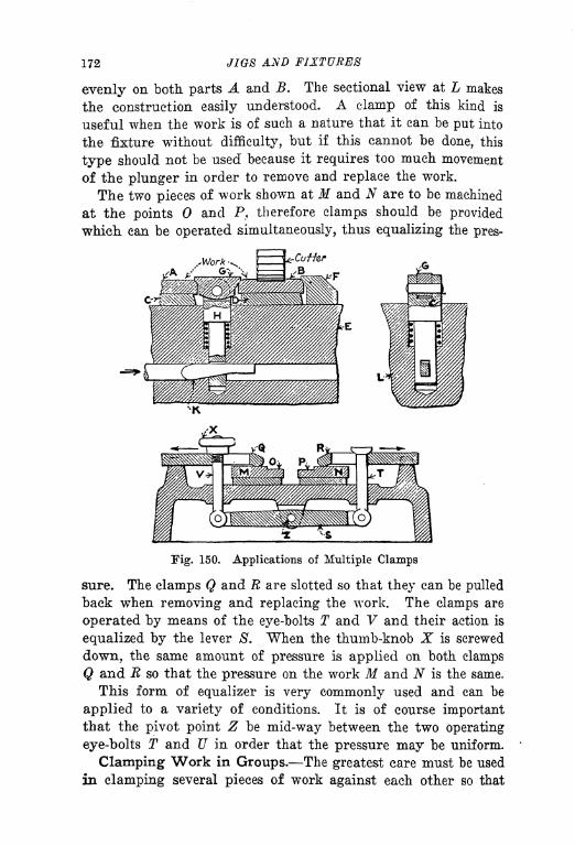
172 JIGS AND FIXTURES
evenly on both parts A and B. The sectional view at L makes
the construction easily understood. A clamp of this kind is
useful when the work is of such a nature that it can be put into
the fixture without difficulty, but if this cannot be done, this
type should not be used because it requires too much movement
of the plunger in order to remove and replace the work.
The two pieces of work shown at M and N are to be machined
at the points and P, therefore clamps should be provided
which can be operated simultaneously, thus equalizing the pres-
ITig. 150. Applications of Multiple Clamps
sure. The clamps Q and E are slotted so that they can be pulled
back when removing and replacing the work. The clamps are
operated by means of the eye-bolts T and V and their action is
equalized by the lever S. When the thumb-knob X is screwed
down, the same amount of pressure is applied on both clamps
Q and E so that the pressure on the work M and N is the same.
This form of equalizer is very commonly used and can be
applied to a variety of conditions. It is of course importantthat the pivot point Z be mid-way between the two operating
eye-bolts T and U in order that the pressure may be uniform.
Clamping Work in Groups. The greatest care must be used
in clamping several pieces of work against each other so that

DKTAIL8 OF MILLING FIXTURE CONSTRUCTION 173
slight erroivs in locating will not cause inaccuracies in the fin-
ished product. A ease in point is .shown in Fig. 151. The workconsists of four bars A, B, C and D on which a small flat sur-
face is to be milled as indicated. The bars are located in the
fixture E so that the bar D is clamped against the under cut
portion F on one side of the fixture. It will be seen that whenthe thumbscrew K is operated, the swinging clamp II strikes
Fig. 151. Clamping Work in Groups
against the bar A throwing it over against 7? which in turn
moves the angular rocking clamp HO that it forces the bar
against /> thus holding the entire group of bars.
For the condition shown this method of clamping is not ob-
jectionable*, but assuming that the bars were to be located for
a key-way as shown at L, If, N and 0, it is evident that accumu-
lated variations would be found in the positions of all of the
slots with the exception of /*. If the bans chanced to be a trifle
large the slot Q would be slightly off center, B would be a little
more HO and 8 still more out of alignment.
174 JIGS AND FIXTURES
This point must always be remembered in designing fixtures
for holding a number of pieces, as a condition like that shown
would be very serious, in that the errors in the key-ways would
make it impossible to obtain a fit on the corresponding female
member.
Another method useful in clamping work in groups, is shown
at T. This is a connecting rod in which a pin has been inserted
in the small end U so that it may be used to locate from during
the progress of the work. The work is located at the large end
by means of another pin which rests on the hardened block Vwhere it is securely held by the sliding clamp W. The fixture Xmust be so arranged that the clamp W can be dropped down in
the direction indicated by the arrow far enough so that the work
can be easily removed. The machining on the rod consists of
straddle milling the two sides of the bosses and saw cutting it
at the same time as indicated.
It is common practice to set up work of this kind in groups,
the number of pieces to be machined at the same time being
governed by the capacity of the machine and the dimensions of
the connecting rod. It is evident that when one side has been
cut, the work can be removed and turned over in the same
fixture so that the other side can be machined.
Design of Hook-Bolt Clamps. Some data have been given
in one of the chapters on drill jigs regarding the design of hook-
bolt clamps in their application to drill jigs. Similar clamps
may be used for milling fixtures, although they should be muchheavier than those used for drilling. Pig. 152 shows a piece of
work A located on the plug B, and which must also be held
firmly on the rectangular end. A special form of combined
hook-bolt and jaw is used in this case. The member D is a
bushing having a jaw cut on it at E against which one side of
the work locates. The rod F has a jaw G at one end and passes
entirely through the bushing D, being operated by the thumb-
knob at the other end H. This entire mechanism will "float,"
and when the thumb-knob is operated, the work is firmly
gripped between the jaws E and G after which the thumb-
screw K can be tightened, locking it positively. A teat screw Lprevents the rod jP from turning. Attention is called to the
manner in which the jaw G is supported at P.
A somewhat similar device is shown holding the work M . This

OF MILLING JP1XTUHK CONSTRUCTION 175
piece is also gripped between jaws at N and and the hook-bolt is released by means of the spring indicated. In this par-ticular ease it is necessary to swing the hook-bolt out of positionin order to remove the work, and the method used is clearlyshown in the end view, the movement of the hook-bolt beingindicated by the arrow and the dotted lines. The same careful
Locating
> H
Mr- '"Wll
Fig. 152, Designs of Hook-Bolt Clamps
provision has been made here for supporting the heel of the
hook-bolt at Q.
An application of a similar principle is shown in the method
of holding the work R. The jaw T grips the work on one side
while the hook-bolt S draws it down and also clamps it. Suitable
beating points must be provided on which the casting may be
supported. This may be done at the point Z by the insertion
of a stud or by some other convenient method. Attention is
one more called to the support of the heel of the hook-bolt at X.
Special Application of Hook-Bolt Clamps. For thin work
that is likely to be distorted either in the cutting or the holding,

176 J1W8 AND
the hook-bolt may frequently be utilized to good advantage.
An application of this kind to a very difficult piece of work
is shown at A in Fig. 153. The work locates on a central stud
B and on hardened ring at C. The arms of the bracket are
straddle milled at D and E and are also finished at F and G.
The material is manganese bronze and the two arms of the
bracket D and E are very frail. Therefore, the method of hold-
ing during the process of machining must take into considera-
Section
Fig. 153. Special Applications of Hook-Bolt Clamps
tion the spring of the material and clamps of special form must
be used. The work must be held close to the points where the
cutting is to be applied and the clamping device must be of a"floating" nature in order that the location of the work on the
stud B and the surface C may not be disturbed.
A pair of hook-bolts using a principle similar to that applied
to the work A in Fig. 1 52 were used for the first operation while
holding the work for the milling of the inside surfaces F and G.
The section taken along the line OP shows the two sides of the
work N gripped at the top by the hook-bolts H and K and at
the bottom by the jaws L and M. The floating action of the

I>KTA1I.N OF AULMNO FIXTURE CONSTRUCTION 177
hook-bolts allows the work to be securely gripped in such a waythat the cutter can machine the piece without distortion.
For the second operation, which consisted of milling the out-Hide surfaces K and 1), a similar arrangement was used. Thework locates on a central plug X through which the hook-boltZ passes. The lower part of the work is held by a floating col-
lar F. .Both the end of the hook-bolt and the collar are cut
Fig, 154. Method of Supporting and Clamping a Thin Casting
away on a slight angle so that the clamping action draws the
work tightly against the central locating plug X and gives great
rigidity during the straddle-milling operation. It may be well
to state that both of these fixtures were made for work requir-
ing great accuracy and that they were operated by girls,
Holding a Large Piece of Thin Work. In milling thin work
it is important that it be held in such a way that vibrations will
not be mi up during the cutting operation. An efficient method
of holding a piece of this kind rigidly, yet without distortion,
JB shown in Fig. 154. The work A. is a deep, thin bronze cast-
178 JIGS AND FIXTURES
ing which is to be milled along the upper part of the flange B.
The work is located on suitable supports under the flange, in
the V-block at C and against the locating block D. It is clamped
as indicated by the arrows at E and F. The clamping action
will obviously tend to distort the sides of the casting and as
there are no lugs on the work to which clamps can be applied,
the results would be very unsatisfactory. The writers have seen
a fixture of this kind in which it was impossible to machine the
work without distortion; in fact it was difficult to machine it
at all on account of the "chatter" induced by the vibrations
of the thin metal walls.
A remedy which was suggested and applied successfully is
indicated at G. This is a "spider" of aluminum having two
supporting studs P which rest on the bottom of the casting.
At H, K, L and AT, screw jacks are located, directly opposite
the outside locating and clamping points.
When setting the work in this fixture the outside clamps are
first set up very lightly and locked in position. The spider G
is then set inside the work and the screw jacks set up tightly
by means of the nuts at N and 0. As the jacks are directly
opposite to the outside holding and locating points a metal-to-
metal contact is obtained which does not distort the work, yet
holds it firmly so that all vibrations are "killed" and the piece
can be milled with speed and precision.
The principles illustrated in this example can be applied in
many similar bases. It is well, however, to note that a much
better way of finishing1 a casting of this sort would be
by using a surface grinding machine instead of a milling
machine.
Equalizing Hook-Bolts. An excellent fixture, which was de-
signed for holding the work A while milling the circular form
D, is shown in Fig. 155. The work has been previously finished
in the hole B and also on the sides E. It is evident that the
action of a large form cutter such as that used in milling the
contour D necessitates exceptionally rigid support for the work
in order to eliminate "chatter" during the operation. The
work is located on a stud at B so that it rests against a solid
surface at E and is located in the other direction by the pin C.
It is clamped back against the shoulder E by means of the hook
bolts F and G, these being operated by the equalising bar H

/>A?7f
.4//,tf OF MILLING FIXTURE CONSTRUCTION 179
through the action of the hand wheel M and the screw K. Thelatter works against a hardened block at L.
The hook belts are provided with camslots at and P which
are so located that when the pressure of the spring at Q and Ris exerted after the handwheel is loosened, the hook bolts turn
90 (leg1
- nd are thus out of the way so that the work can be
readily removed. In other words, when the hook bolts are
Fig, I. Fixture with Equalizing Hook Bolts
piiRhed out away from the work by means of the springs, a pin
in the campath maktn* them revolve in the manner noted. Anadditional refinement can he wed as shown at F, if conditions
warrant It, by mounting1 the hanclwheel on the shaft X in which
a bayonet lock Z In cut. A method like this would make the
operation of the mochanwrn somewhat faster than the example
previously dew-ribed. The advantages of this type of fixture
are the extreme rigidity that IB obtained and the fact that the
180 JIGS AND FIXTURES
operator is not obliged to put his hands near the cutter. It is
rapid in operation and the construction is such that the upkeepis very economical. The use of air-operated chucks and other
clamping devices is becoming more and more general for work
requiring careful holding or rapid operation. The majority of
present day factories are equipped with air compressors and
Work
Fig. 156. Principles of Pneumatic Clamping
pipe lines extending to the various departments of the shop.
With such equipment, advantage should be taken of the oppor-
tunities for using air pressure to operate fixtures of various
kinds.
Principles of Pneumatic Clamping. Pig. 156 shows a few
diagrams which will assist the designer in understanding the
principles of pneumatic clamping. The work shown at A is being
held for the milling operation indicated between the jaws B
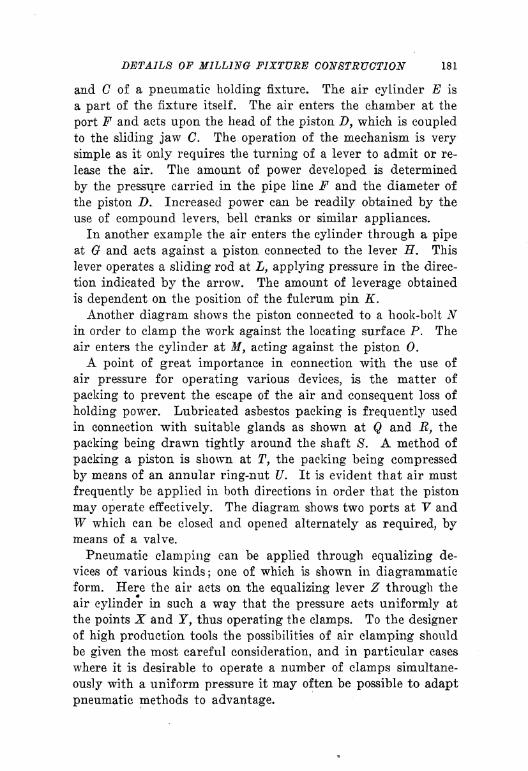
DETAILS OF MILLING FIXTURE CONSTRUCTION 181
and C of a pneumatic holding fixture. The air cylinder E is
a part of the fixture itself. The air enters the chamber at the
port F and acts upon the head of the piston D, which is coupledto the sliding jaw C. The operation of the mechanism is very
simple as it only requires the turning of a lever to admit or re-
lease the air. The amount of power developed is determined
by the pressure carried in the pipe line F and the diameter of
the piston D. Increased power can be readily obtained by the
use of compound levers, bell cranks or similar appliances.
In another example the air enters the cylinder through a pipeat G and acts against a piston connected to the lever H. This
lever operates a sliding rod at L, applying pressure in the direc-
tion indicated by the arrow. The amount of leverage obtained
is dependent on the position of the fulcrum pin K.
Another diagram shows the piston connected to a hook-bolt Nin order to clamp the work against the locating surface P. The
air enters the cylinder at M9 acting against the piston 0.
A point of great importance in connection with the use of
air pressure for operating various devices, is the matter of
packing to prevent the escape of the air and consequent loss of
holding power. Lubricated asbestos packing is frequently used
in connection with suitable glands as shown at Q and R, the
packing being drawn tightly around the shaft S. A method of
packing a piston is shown at T, the packing being compressed
by means of an annular ring-nut U. It is evident that air must
frequently be applied in both directions in order that the piston
may operate effectively. The diagram shows two ports at V andW which can be closed and opened alternately as required, bymeans of a valve.
Pneumatic clamping can be applied through equalizing de-
vices of various kinds;one of which is shown in diagrammatic
form. Here the air acts on the equalizing lever Z through the
air cylinder in such a way that the pressure acts uniformly at
the points X and Y, thus operating the clamps. To the designer
of high production tools the possibilities of air clamping should
be given the most careful consideration, and in particular cases
where it is desirable to operate a number of clamps simultane-
ously with a uniform pressure it may often be possible to adapt
pneumatic methods to advantage.

CHAPTER IX
VISE-JAWS AND VISE FIXTURES
SPECIAL AND SWIVEL JAWS DEVICES FOR INSURING ACCURACY
QUICK OPERATION DEVICES FOR EQUALIZING PRESSURE-
AUTOMATIC EJECTORS.
The use of vises with plain or special jaws oftentimes makes
it possible to hold small work advantageously for milling, shap-
ing and drilling operations. Generally speaking vise-jaws are
used more often for milling than for other operations. Vises
can be adapted and used with special jaws to hold irregularly-
shaped work which would be difficult to hold in any other way.
It is unfortunate that tool engineers do not specify the use
of vises more frequently, for their advantages are so evident
and their adaptability so great that they can be used profitably
in many cases which would otherwise require expensive fixtures.
The standard type of milling machine vise used for manufac-
turing in many shops is not adapted for very heavy cutting. It
was designed originally for toolroom work to provide a means
of holding flat and round stock for light cuts. It is theoretically
wrong in principle as the thrust of the cut is taken by the
t> movable jaw instead of by the solid jaw.
I'Fig. 197 shows a vise of this kind at A. Note that the movable
Jjaw B is intentionally made long and heavy in order to make
':'it as rigid as possible. In reality, although the vise is not de-
,\signed for very heavy cutting, good results may be obtained
;1 from it and many factories use no other type. The jaw is
| operated by means of a screw.
|The vise shown at C is designed especially for manufactur-
|ing- This type takes the thrust of the cut on the solid jaw D.
| The movable jaw E is a unit with the slide F on which the levers
jjj
G and H are mounted. By loosening the binding lever G and
I moving both levers along in the slot of slide F various openings
Pof the jaws can be easily made according to the capacity of the
*230

VISE-JAWS AND VISE FUTURES 231
vise. In operation the cam lever H is set until the jaws grip
the work firmly, after which the binding lever is tightened. Asthe latter is slightly eecentrie to the cam lever, the locking action
is improved and greater leverage obtained. Both of the vises
illustrated can be furnished with special and swivel jaws.
Fig. 197. Examples of Milling and Manufacturing Vises
In addition to the two types of vises shown there are special
forms for toolroom use. The vise principle used is generally
like that shown at A, the difference in design being in the method
of mounting the vise so that it can be swiveled in either a horizon-
tal or vertical plane. A manufacturing vise operated by com-
pressed air was described in a previous chapter.
Special vises can be made up for extraordinary conditions if
it is found that standard vises cannot be used. If it is impos-
sible to grip the work properly with special jaws in a standard
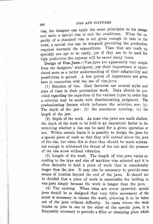
23a JIGS AND FIXTURES
vise, the designer can apply the same principles to his design
and' make a special vise to suit the conditions. When the ca-
pacity of a standard vise is not great enough to take in the
work, a special vise can be designed providing the production
required warrants the expenditure. Vises that are made up
specially are apt to be costly, yet if they are to be used for
high production the expense will be saved many times.
Design of Vise-Jaws. Vise-jaws are apparently very simple
from the designers' standpoint, yet their importance is appre-
ciated more as a better understanding of their adaptability and
possibilities is gained. A few points of importance are given
here in connection with the use of vise-jaws.
(1) Selection of vise. Most factories use several styles and
sizes of vises in their production work. Data should be pro-
vided regarding the capacities of the various types in order that
a selection may be made with discriminating judgment. The
predominating factors which influence the selection are: (a)
The depth of the jaw: (b) the maximum opening; (c) the
length of the jaw.
(2) Depth of the work. As most vise-jaws are made shallow,
the depth of the work to be held is an important factor in de-
termining whether a vise can be used for a given operation or
not. Within certain limits it is possible to design the jaws for
a special piece of work so that they will extend above the jaws
of the vise, but when this is done they should be made substan-
tial enough to withstand the thrust of the cut and the pressure
of the vise screw without vibration.
(3) Length of the work. The length of vise-jaws varies ac-
cording to the type and size of machine vise selected and it is
often desirable to hold a piece of work that is considerably
longer than the jaw. It may also be necessary to provide some
means of location beyond the end of the jaws. It should not
be decided that a piece of work is unsuitable for holding in
vise-jaws simply because the work is longer than the jaws.
(4) Vise opening. When vises are screw operated, special
jaws should be so designed that very little movement of the
screw is necessary to release the work, allowing it to be taken
out of the jaws without difficulty. In cases where the work
locates on pins in one or the other of the special jaws, it is
frequently necessary to provide a filler or clamping plate which

VISE-JAWS AND VISE FIXTURES 233
can be thrown out of the way when the jaws are released In
order to avoid too much movement. This matter will be taken
up in detail later in this article.
(5) Formed jaws. Irregular work such as small forgings,
castings and other parts which require milling operations are
frequently held by means of special jaws which are4k formed
out" by the toolmaker to fit the contour of the work. "When
jaws of this kind are designed, a clamping action must be ob-
tained on the work close to the point where the cut is to be
made. For example, in a forging having a ball end, the jaw
Fig. 198. General Diagrams of Vise-Jaws
would be formed to hold the ball loosely in order to obtain the
location, while the work would be gripped at other points where
the cutting action is to take place. There are so many varieties
of formed jaws that it has not been deemed essential to take
up their design in this article. Each individual case must be
treated differently according to the shape of the piece and the
general requirements of the work.
General Diagram of Vise-Jaws. Fig. 198 shows a standard
type of vise-jaws, such as are usually supplied with a milling
machine vise. Attention is called to the fact that the dimensions
A and B are fixed, according to the style and size of the vise
used. It is necessary therefore to ascertain these dimensions
before proceeding with the design of any special jaws. The
dimension C is also important as it determines the maximum size

232 JIGS AND FIXTURES
vise, the designer can apply the same principles to his design
and' make a special vise to suit the conditions. When the ca-
pacity of a standard vise is not great enough to take in the
work, a special vise can be designed providing the production
required warrants the expenditure. Vises that are made up
specially are apt to be costly, yet if they are to be used for
high production the expense will be saved many times.
Design of Vise-Jaws. Vise-jaws are apparently very simple
from the designers7
standpoint, yet their importance is appre-
ciated more as a better understanding of their adaptability and
possibilities is gained. A few points of importance are given
here in connection with the use of vise-jaws.
(1) Selection of vise. Most factories use several styles and
sizes of vises in their production work. Data should be pro-
vided regarding the capacities of the various types in order that
a selection may be made with discriminating judgment. The
predominating factors which influence the selection are: (a)
The depth of the jaw: (b) the maximum opening; (c) the
length of the jaw.
(2) Depth of the work. As most vise-jaws are made shallow,
the depth of the work to be held is an important factor in de-
termining whether a vise can be used for a given operation or
not. Within certain limits it is possible to design the jaws for
a special piece of work so that they will extend above the jaws
of the vise, but when this is done they should be made substan-
tial enough to withstand the thrust of the cut and the pressure
of the vise screw without vibration.
(3) Length of the work. The length of vise-jaws varies ac-
cording to the type and size of machine vise selected and it is
often desirable to hold a piece of work that is considerably
longer than the jaw. It may also be necessary to provide some
means of location beyond the end of the jaws. It should not
be decided that a piece of work is unsuitable for holding in
vise-jaws simply because the work is longer than the jaws.
(4) Vise opening. When vises are screw operated, special
jaws should be so designed that very little movement of the
screw is necessary to release the work, allowing it to be taken
out of the jaws without difficulty. In cases where the work
locates on pins in one or the other of the special jaws, it is
frequently necessary to provide a filler or clamping plate which

VISE-JAWS AND VIBE FIXTURES 233
can be thrown out of the way when the jaws are released in
order to avoid too much movement. This matter will be taken
up in detail later in this article.
(5) Formed jaws. Irregular work such as small forcings,
castings and other parts which require milling operations are
frequently held by means of special jaws which are "formedout" by the toolmaker to fit the contour of the work. Whenjaws of this kind are designed, a clamping action must be ob-
tained on the work close to the point where the cut is to be
made. For example, in a forging having a ball end, the jaw
Fig. 198. General Diagrams of Vise-Jaws
would be formed to hold the ball loosely in order to obtain the
location, while the work would be gripped at other points where
the cutting action is to take place. There are so many varieties
of formed jaws that it has not been deemed essential to take
up their design in this article. Each individual case must be
treated differently according to the shape of the piece and the
general requirements of the work.
General Diagram of Vise-Jaws. Fig. 198 shows a standard
type of vise-jaws, such as are usually supplied with a milling
machine vise. Attention is called to the fact that the dimensions
A and B are fixed, according to the style and size of the vise
used. It is necessary therefore to ascertain these dimensions
before proceeding with the design of any special jaws. The
dimension C is also important as it determines the maximum size
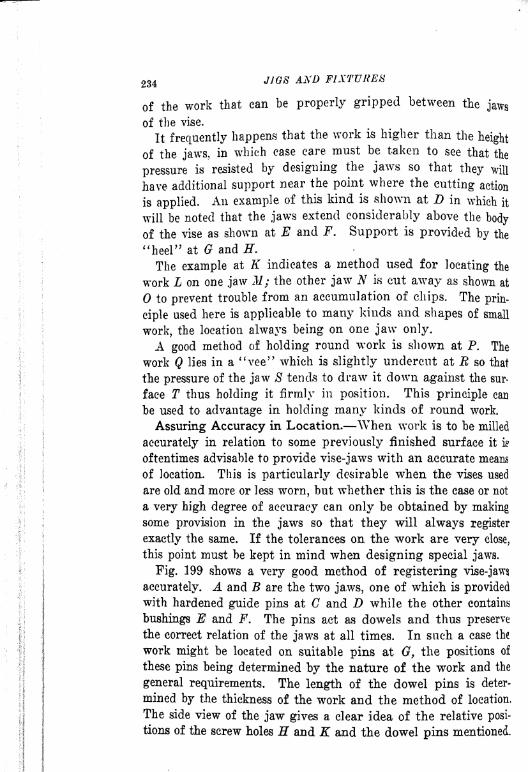
234
of the work that can be properly gripped between the jaws
of the vise.
It frequently happens that the work is higher than the height
of the jaws, in which case care must be taken to see that the
pressure is resisted by designing the jaws so that they will
have additional support near the point where the cutting action
is applied. An example of this kind is shown at D in which it
will be noted that the jaws extend considerably above the body
of the vise as shown at E and F. Support is provided by the
"heel" at and H.
The example at K indicates a method used for locating the
work L on one jaw M; the other jaw N is cut away as shown at
to prevent trouble from an accumulation of chips. The prin-
ciple used here is applicable to many kinds and shapes of small
work, the location always being on one jaw only.
A good method of holding round work is shown at P. The
work Q lies in a "vee" which is slightly undercut at R so that
the pressure of the jaw S tends to draw it down against the sur-
face T thus holding it firmly in position. This principle can
be used to advantage in holding many kinds of round work.
Assuring Accuracy in Location. When work is to be milled
accurately in relation to some previously finished surface it is
oftentimes advisable to provide vise-jaws with an accurate means
of location. This is particularly desirable when the vises used
are old and more or less worn, but whether this is the case or not
a very high degree of accuracy can only be obtained by makingsome provision in the jaws so that they will always register
exactly the same. If the tolerances on the work are very close,
this point must be kept in mind when designing special jaws.
Fig. 199 shows a very good method of registering vise-jaws
accurately. A and B are the two jaws, one of which is provided
with hardened guide pins at C and D while the other contains
bushings E and F. The pins act as dowels and thus preserve
the correct relation of the jaws at all times. In such a case the
work might be located on suitable pins at 0, the positions of
these pins being determined by the nature of the work and the
general requirements. The length of the dowel pins is deter-
mined by the thickness of the work and the method of location.
The side view of the jaw gives a clear idea of the relative posi-
tions of the screw holes H and K and the dowel pins mentioned.
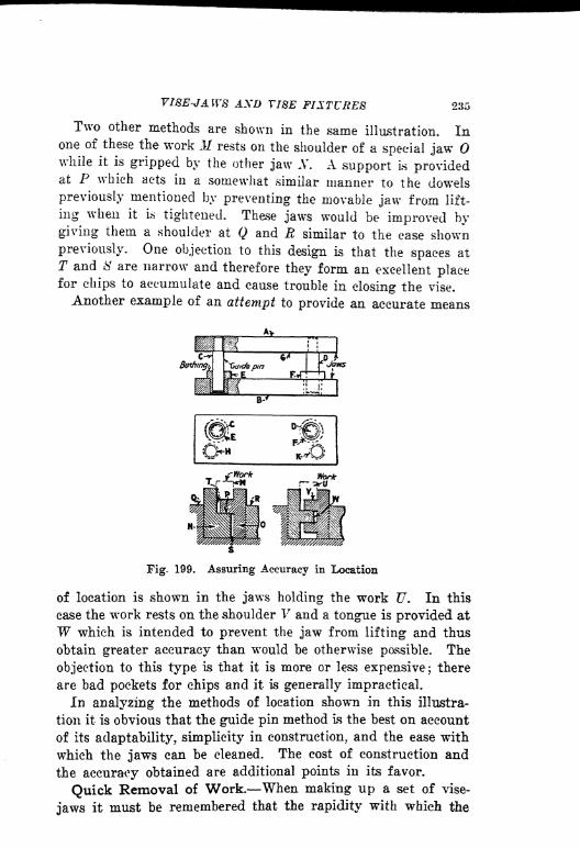
VISE-JAWS AND VISE FIXTURES 235
Two other methods are shown in the same illustration. Inone of these the work M rests on the shoulder of a special jawwhile it is gripped by the other jaw N. A support Is providedat P which acts in a somewhat similar manner to the dowels
previously mentioned by preventing the movable jaw from lift-
ing when it is tightened. These jaws would be improved bygiving them a shoulder at Q and R similar to the ease shownpreviously. One objection to this design is that the spaces at
T and 8 are narrow and therefore they form an excellent placefor chips to accumulate and cause trouble in closing the vise.
Another example of an attempt to provide an accurate means
Fig. 199. Assuring Accuracy in Location
of location is shown in the jaws holding the work U. In this
case the work rests on the shoulder V and a tongue is provided at
W which is intended to prevent the jaw from lifting and thus
obtain greater accuracy than would be otherwise possible. The
objection to this type is that it is more or less expensive; there
are bad pockets for chips and it is generally impractical.
In analyzing the methods of location shown in this illustra-
tion it is obvious that the guide pin method is the best on account
of its adaptability, simplicity in construction, and the ease with
which the jaws can be cleaned. The cost of construction and
the accuracy obtained are additional points in its favor.
Quick Removal of Work. When making up a set of vise-
jaws it must be remembered that the rapidity with which the

236 JIGS AND FIXTURES
vise is operated is dependent to a great extent on the amount
of opening- necessary to remove and replace the work. Whenthe latter is of such a nature that it must be located on a stud
and removed from the stud after the operation, a considerable
opening to the jaws may be required. When a cam operated
vise is used a certain amount of opening can be made rapidly,
and this may serve to take care of many conditions, but
when the regular type of milling machine vise is used, everyhalf revolution of the screw means that the operator is obliged
to remove his wrench and replace it again. This takes time
and is a decided objection if the jaws need to be opened rapidly.In order to obviate this trouble it is customary to provide a
Fig. 200. Provision for Quick Removal of Work
filler block to lie between the work and one jaw. By taking outthis filler block the work can be removed and replaced readilyand not more than a half turn of the screw is required to pro"-
vide sufficient opening. The filler can be made in the form ofa loose piece or it can be pivoted to one jaw so that it can be
swung out of the way when not in use.
Fig. 200 shows a pair of jaws at A and B, the jaw A holdingfour collars C by means of the locating block D. If no provi-sion were made for rapid removal of the work it would be neces-
sary to open the jaws the distance shown at E in order to allowall four collars to be removed at once. To provide against sucha contingency, the jaw B is provided with a swinging block Fwhich acts as a clamp against the work and yet is quickly re-
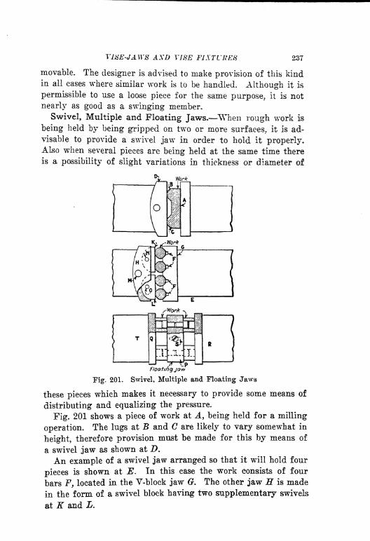
VI8E-JA.W8 AXD YJ8E FIXTURES 237
movable. The designer is advised to make provision of this kindin all cases where similar work is to be handled. Although it is
permissible to use a loose piece for the same purpose, it is not
nearly as good as a swinging member.
Swivel, Multiple and Floating Jaws. When rough work is
being held by being gripped on two or more surfaces, it is ad-
visable to provide a swivel jaw in order to hold it properly.Also when several pieces are being held at the same time there
is a possibility of slight variations in thickness or diameter of
/"toorting join
Fig. 201. Swivel, Multiple and Floating Jaws
these pieces which makes it necessary to provide some means of
distributing and equalizing the pressure.
Fig. 201 shows a piece of work at A, being held for a milling
operation. The lugs at B and C are likely to vary somewhat in
height, therefore provision must be made for this by means of
a swivel jaw as shown at D.
An example of a swivel jaw arranged so that it will hold four
pieces is shown at E. In this case the work consists of four
bars F, located in the V-block jaw G. The other jaw H is made
in the form of a swivel block having two supplementary swivels
at K and L.

238 JIGS A1?D FIXTURES
The designer should remember that all of the pressure of the
jaws will come upon the pins at M, N and if made like the
illustration. It would be much better practice to make the pins
mentioned a loose fit in the swivel and let the pressure come
against the radius at the back of each of the blocks. The pins
should only act as retainers and not take any pressure.
A supplementary or floating jaw is sometimes used to hold
several pieces, as shown at P. This method is useful where sev-
eral pieces are to be milled at one time. The block lies between
the two jaws and R and is located by means of a pin in an
elongated slot shown at S. In operation, the work is loaded by
removing the floating jaw P and placing the piece on it after
/^operation Cutter
\i Cutter
operatic*
Fig. 202. Method of Locating and Holding Long Work
which it is set in position between the jaws and clamped in
place. This method is useful for handling small pieces of workwhen a number of them are to be located at one time. If there
is likely to be a variation in the length of the pieces, the jaw Qcan be made in swivel form to take care of the variations.
It is sometimes possible to use the same set of jaws for morethan one operation on the same piece of work, and when this
can be done without interfering with the production scheduleit is obviously an advantage. Occasionally jaws can be providedwith two sets of pins or other means of location and cutterscan be arranged on the arbor so that both operations can bedone at the same time
; one piece being finished while the otheris being rough-milled. When bar work is to be milled it is often
possible to use the same jaws for several operations. An exam-ple of this is shown in Fig. 202, in which the work A is a bar

VI8E-JAW8 AXD VltiE FIXTURE 239
somewhat longer than the jaws in which it is being held. The
bar is located endwise by the stop at B, this stop being a part of
the extension C which is fastened to one jaw. An end view of
the jaws is shown at D and E, where it will be seen that the
jaw E is slightly undercut to assist in holding the work. The
locating bar C is fastened to the jaw E and acts as a support
for the work as indicated.
The first operation consists in cutting a slot in the end of the
bar at F. The locater B is made so that it will fit this slot,
Hfor*
Work
Work
Fig. 203. Examples Showing Methods of Location
therefore not only can the work be set up for the second opera-
tion with the same set of jaws, but the second operation will be
properly located in relation to the first The second operation
consists of milling a longitudinal slot in the bar as shown
at H.
Location of Small Work. In locating small work in vise-
jaws, a great deal depends upon the shape of the piece. Fig.
203 shows an excellent example of a production job on a small
piece of work on which two operations are being performed at
the same time. The work A is located on pins at B, and D

240 J108 AND FIXTURES
in the jaw E while the slot is cut at F. This is the first opera-
tion on the work after it has been cut off. In the same set of
jaws the piece is held in another position as shown at G and
located by the milled slot F, using locating pins at E, K and L.
This operation mills the slots at M and N and also cuts the work
into two pieces by means of the slotting cutter 0. As it is pos-
sible that the work might not be located firmly against the two
pins at B and H, provision is made to insure their contact at
these points. By using a pair of fiat springs at P and Q the
work will be automatically forced over against the locating pins
without particular attention on the part of the operator.
The work shown at R must be located from the shoulder 8.
This brings up a point in design which is frequently neglected
when vise-jaws are made and that is the alignment of the jaws.
It is always advisable to make the shoulder location on one jaw
only as shown at T, rather than to attempt to line up two shoul-
ders on opposite jaws. Another example of a shoulder location
is shown at V, in which case it will also be noted that the loca-
tion is on one jaw only. There are occasional cases when this
rule can be overlooked, for example, when dowel pins are used
in the jaws to insure accuracy as shown in Fig. 199. However,it is safer to follow the rule of locating on one jaw only.
Vise-Jaws Designed for Several Consecutive Operations.It is interesting to note the adaptability of vise-jaws for hold-
ing small parts which have several consecutive milling opera-tions. An example which illustrates this point is shown in Fig.
204. The consecutive operations are shown on the rectangularblock in the illustrations 1, 2, 3 and 4. The work is first cut
off from a rectangular bar so that it takes the form 1. The next
operation is the forming of the radius shown at 3, and the fourth
operation is the profiling of the circular cut shown at 4c-A. In
the first operation the bar B is placed in the jaws shown until
it strikes the end stop C. The jaws are then tightened and the
portion D is cut off. "When the jaws are loosened the pieceslides down the inclined plane E into a box provided for it andthe bar B is pushed forward again until it strikes the stop C,after which the eutting-off operation is repeated.
In the next operation the work is held by means of the jawsF and G while the straddle milling cut is made at H and K.This operation machines the piece to length, a suitable allow-

V18E-JAW8 AND VISE FIXTURES 241
anee having been made for this operation while cutting off the
work.
The next operation is the cutting of the radius as shown at L.
The work is held by suitably formed jaws and is located against
the pins If, Ar and by means of the thumbscrew P, which is
so placed that it is outside of the milling machine vise and can
therefore be easily manipulated. These three examples have
LZG di QSaw -
o
Fig. 204. Vise-Jaw Design for Several Consecutive Operations
been given to familiarize the designer with the methods used for
progressive operations on small parts. Many applications can
be made of the principles shown here.
Equalizing Pressure by Means of Beeswax Jaws. There
are instances when a number of pieces are to be held at the same
time in a set of vise-jaws and yet it is difficult to make sure
that all of the pieces are held firmly, due to slight variations
in the work. There are also irregular forms which have to be
supported at several points while cutting, and which must in-

242 JIGS AND FIXTURES
corporate some method of equalizing the supports to take care
of slight inaccuracies in the work. The principle shown in Pig.
205 can be applied to a variety of conditions, and it has been
used successfully for holding work which would be difficult to
support by any other known method. In the example shown
there are five parts A, B, C, D and E, located in V-blocks in the
jaw F. The other jaw is equipped with a series of plungers G
which are lapped to an accurate sliding fit in the jaw jff. The
chamber K in this jaw is filled with beeswax or heavy grease.
When this mass is compressed by means of the screw at L the
vise pins G are forced out until they all come in contact with
Work
Fig. 205. Equalizing Pressure by Means of Bees-Wax Jaws
the work. After the first adjustment has been made by meansof the screw the pins will automatically equalize themselves so
that a positive contact will be assured on each one. In makingup a set of jaws of this sort care must be taken that the various
fits for the pins and the screw are carefully made in order to
prevent leaks when the pressure is applied.Vise Fixture for Small Work. Occasionally a milling opera-
tion has to be performed on a piece of work which is difficult
to locate in vise-jaws. When a condition of this kind arises it
is sometimes possible to design a vise fixture in which the workcan be located and clamped and then the fixture itself placedbetween the vise-jaws for the milling operation. A case in pointis shown at A in Fig. 206. This piece of work has previouslybeen drilled and reamed at B and C and faced on both sides.
It is located on two pins in the holes and clamped by means of

VISE-JAWS AND VISE FIXTURES 243
the strap clamp D. This clamp is so arranged that it swings
away from the work until the pin E strikes the stop pin F in
the body of the fixture, thus permitting the work to be removed.
When the work is clamped the point of the screw G rides up on
the angular surface of the block H and a wedging action takes
place which makes the operation very rapid. The fixture K
-0J
KJtork
'Cuff
^ Jaws-
Elev.Showing Fixture Clamped m Vise Sectron Shoeing Screw
Fig. 206. Vise Fixture to Hold Small Work
locates between the jaws of a standard vise which clamps it at
the points L, M, N and 0. Provision is made at some convenient
point so that end location in the vise-jaws will be assured. The
operation to be done in this fixture is the cutting of the slot
at P. Obviously this method of holding is convenient and at
the same time the fixture is cheap and can be operated rapidly.
Cases are found now *nd then when a fixture of this kind can
be used to advantage.
244 JIGS AND FIXTURES
Special Vises with Equalizing Jaws. As a vise of suitable
dimensions to handle the work A shown in Fig. 207 could not
be obtained, a special vise was designed. The work is located
by means of two pins at D in the solid member of the vise. The
work to be done is the cutting of the two slots B and C.
The swivel block E fits the radius at F in the sliding member
which passes under the rigid block 0. The pin H acts as a re-
tainer only and is a free fit in the hole. In operation the cam
lever K acts against the hardened block L, clamping the work
firmly. The body of this vise is made of cast iron and the slid-
Fig. 207. Special Vise with Equalizing Jaw
ing parts are all carefully fitted to insure the necessary ac-
curacy. It will be noted that construction of this vise is such
that the cutting action comes against the solid member and not
against the movable jaw.There are occasional cases when special vises can be made up
to suit a particular condition but unless the conditions are suchthat the expense of a special vise is warranted, it is better to
use a standard vise.
^Ejectors for Vise Jaws. As a refinement in the design of
vise-jaws it is often necessary to provide means for removingthe work after the milling operation has been done. Many timesthe shape and position of the work is such that it can only be
V18E-JAW8 AXD TIKE FIXTURES 245
removed with difficulty. For eases of this kind ejectors can be
provided which will facilitate the operation. Several examplesof ejectors are shown in Fig. 208. The work A is to be located
on the stud B in the vise-jaw C. As it would be difficult to
locate this work easily it is placed on the movable jaw D so that
Ejectors,,
Fig. 208. Various Types of Ejectors for Vise Jaws
it rests on the two pins at K and L, which locate it approxi-
mately. Then, as the jaw is moved up into position the beveled
end of the stud B enters the hole, thus locating the work cor-
rectly. After the work has been done, the ejectors F and 6
pull the work away from the stud, making it easy for the op-
erator to remove it. This method precludes the necessity of
using a screwdriver to pry the piece off from the stud, which
246 JW8 A-ND FIXTURES
might result in damage to the work or spring the stud out of
alignment.
The form of ejector shown at M can be used either by itself
or in connection with a piece of work like that at A. Assumingthat this work is the same as the other piece except that it is
smaller and thinner, it would be difficult for the workman to
get his fingers into position to remove the work. Ejectors similar
to those shown at F and could be used here to pull the work
off from the locating stud, but after it had been removed it
would still lie in the jaw in such a position that the workman
could not get hold of it easily. By making use of the lever N,
however, the piece could be raised so that it would be easily
accessible.
Attention is called to the construction of the plungers
which provide the spring pressure for the ejector. This method
is entirely different from the other and it has some advantages,
although it is a little more expensive in construction. There is
no danger of this type of spring plunger being clogged up with
chips or dirt.
The work P is located on a button at Q and it will be seen
that such a piece might be difficult to remove after it had been
machined. Using the lever S to operate the plunger JR makes
the operation much easier and the work can be removed with-
out difficulty.
In the design of vise-jaws, particularly when small and thin
pieces are to be handled, the ejector is an important factor as
it assists greatly in cutting down the operating time. In addi-
tion to this, the work can be removed readily and without injuryand as there is no necessity for hammering or otherwise injur-
ing the fixture, a better product is assured.

CHAPTEE X
BROACHES AND BROACHING FIXTURES
PRINCIPLES OP DESIGN TOOTH-SPACING AND CHIP-CLEARANCEBURNISHING KEYWAY BROACHING MULTIPLE FIXTURESINDEX BROACHING SPIRAL BROACHING.
The process of broaching is very old and dates back several
hundred years when holes of various shapes were made in metal
by forcing one or more tools of the required shape through the
work by driving with a hammer or other means. Later on, short
broaches with teeth were made and pushed through the work
by means of hand presses or those operated by power. It wasnot until 1901, however, that the present process of pullingbroaches through the work was developed. Before this time
broaches were pushed through the work; now they are pulled
through it in the majority of cases.
Push broaches are short while pull broaches are long and it
is evident that the latter types possess distinct advantages over
the former, in that a greater number of teeth can be used, and
as a consequence the cutting action is more uniform and sizes
can be held mucti more easily. In addition to this, broaches that
are pulled through the work do not tend to "run" or crowd
to one side or the other, which fact is also a decided advantage.
We must qualify this statement somewhat, because a dull broach
will run out of alignment more or less. If the pull broach is
sharp, however, it should run true if properly used.
Important Points in Design. There are a number of factors
which influence the design and general construction of broaches
and broaching fixtures. The tool engineer who attempts the de-
sign of tools of this sort must first familiarize himself with the
important features and method of operating a broaching ma-
chine. There are several types on the market, the general fea-
tures of which are more or lass similar. Different methods of
centralizing the broach in relation to the work are used, but
247

248 JIGS AXt> FIXTURES
other than this the construction is much the same in all types.
In the horizontal types of machines, the work rests or is held
by a fixture of some sort against a vertical faceplate through
which the broach passes while in operation. Some types of
broaching machines have only one spindle while others have two.
In the two spindle variety one spindle is operating while the
other is returning so that the lost time in setting up is reduced
to a minimum.
Let us now consider the various points of importance in con-
nection with the design of fixtures for broaching and also some
pertinent matters regarding the broaches themselves:
(1) Material To Be Broached. As in other machining opera-
tions, the material to be broached is an important factor in deter-
mining what tools are best adapted for the work. So, in broach-
ing, the material affects not only the design of the broach but
the fixture that is to be used as well. The shape of the broach
teeth and the amount of material that each tooth will have to
remove are important factors which influence the production.
(2} Thickness of the Metal. This matter is of great impor-tance in broaching operations as it affects the spacing of the
broach teeth. It is difficult to cover the situation in a generalnote but detailed information will be given on the subject later
on in this article.
(5) Production Required. This matter must always be taken
into consideration in designing a fixture as the cost of tools
should be as nearly as possible in proportion to the amount of
work that is to be produced. In broaching fixtures, this factor
may easily affect the design of both broach and fixture and also
determine the type of machine on which the work should be
done.
(4) Preparation of Work Before Broaching. Unlike manyother operations, work that is to be broached usually requires acertain amount of preliminary machining. A hole must be pro-vided in which to insert the broach and a square surface shouldbe provided on that side of the work which locates against the
faceplate of the broaching machine. This point is of importanceand, unless due consideration is given to it, may affect the ac-
curacy of the work to an appreciable extent.
(5) Accuracy Required. It is seldom that a broached hole is
required within an accuracy greater than from 0.001 to 0.002 in.

BROACHES AND BltOACHIXti FIXTURES 249
and as it is not particularly difficult to keep within these limits
it is evident that the broaching process can be applied to manykinds of work in general manufacturing. If very close toler-
ances are required both roughing and finishing cute can be takenas in other machining processes. In some cases it is necessaryto locate a broached hole in relation to another one which has
been previously machined, in which case it may be found de-
sirable to use the outboard sliding support with which broachingmachines are provided in order to support the end of the broach
and keep it in correct alignment while in operation.
(6) Lubrication. All broaching machines are provided with
means of directing a stream of cutting lubricant into the hole
while it is being broached, and this must be considered in mak-
ing up a fixture in order that the lubricant may reach every
part of the broach. For example, a square hole should be
broached with a corner upward and not "flat, so that the lubri-
cant will reach all four sides of the broach and will not spatter
off as it might otherwise. In broaching spiined work, the channel
between two of the splines should be at the top, so that it will
retain the liquid and serve to carry it into the hole with the
broach. The kind of lubricant used depends upon the material
that is to be cut.
(?) Rigidity. It is highly important that all work that is
to be broached should be supported properly in order to pre-
clude the possibility of"chatter" or of the material springing
away from the broach during the process, which would cause
inaccuracies and tend to injure the broach. When several pieces
are to be broached together or when the work is thin, particular
attention must be given to the method of holding. Suitable sup-
ports or jacks must be provided for work which is irregular in
shape in order to avoid any of the troubles mentioned.
(8) Clamping. Various types of clamps have been described
in previous chapters so that it is only necessary to refer to some
of these to cover practically all conditions of clamping such as
may be required in broaching fixtures. Particular attention
should be paid to any work which is thin or of irregular shape
so that there will be no distortion due to improper methods of
clamping.
(9) Cost of Tools. Usually the fixtures used for broaching
are simple in design and inexpensive to make. There are cases,
250 JW8 ^ND FIXTURES
however, when something more elaborate is needed in order to
decrease the setting up time or when the work is of such a char-
acter that it cannot be supported and clamped properly in a
simple type of fixture.
Broaching Methods. In considering the design of broaching
fixtures, the designer must first realize that there are two meth-
ods in use. Fig. 209 illustrates diagrammatically both forms of
broaching processes. The work shown at A is set up on the table
of an arbor press at 5. The broach C is short and is pushed
through the work by means of the press spindle. Attention is
called to the fact that all push broaches must be short and that
the usual method is to push several of them through the work,
one after another, each one being so proportioned that it will
^Push brooch
Work.
LSr
Pull Broach
Fig. 209. Types of Broaching
remove a little more stock than the one which preceded it. The
end D should be so made that it will act as a pilot when enter-
ing the work. The teeth are so proportioned that each tooth is
slightly larger than the preceding one. The amount of this
variation is dependent upon the material to be cut and the shapeand size of the hole.
The piece of work shown at E is broached by pulling the tool
through the work instead of pushing it as in the first instance.
This work is done on a horizontal broaching machine designed
strictly for the broaching process. In contrast with the other
example shown, the broach F is long, usually from 24 to 36 in.,
depending on the capacity of the machine and also upon the
amount of stock to be removed. It will be noted that the pull-
ing action of this broach is resisted by the faceplate G on the
machine itself. The portion H acts as a pilot and centers the
broach in the hole, as in the preceding example.
Broaching an Oil Groove. A bushing which acts as a shaft
bearing is often provided with an oil groove. When the work

BROACHES AXD BROACHING 251
is manufactured in small lots a cold chisel of the proper form
is frequently used and the operation is done by hand. If the
production is large, other methods can be used according to the
depth of the groove, the material which is to be cut, and the
machines which are available.
Fig. 210 shows a piece of work A in which an oil groove is
cut at By this groove being shallow as indicated in the illustra-
tion. In this case the work rests on a bushing C and the ma-
Work-
Fig. 210. Simple BroaeMng Operation
chine used can be an arbor press or other similar machine. It
might be possible to use a drill-press spindle to apply the pres-
sure if no other machine were available. The cutter or broach
bar D is a sliding fit in the bushing and an adjustable cutter
is provided at E. By means of the screw and binding shoe Fthe cutter can be held in any position, desired.
The bar itself is located in the bushing by means of the teat
screw (7 which enters the slot H in the bar. It is evident that
the depth of the groove is controlled by the position of the cut-
ter, and there may be cases when two or three cuts are needed
in order to produce the desired results. Oil grooves are usually

252 JIGS AND FIXTURES
shallow so that a single cut will often be found sufficient. In
the event of a deep cut being required, it would be better to
run the work through several times, adjusting the cutter a little
more for each successive cut, rather than to attempt an adjust-
ment several times on each piece of work. It would be pos-
sible, however, to make a bar with rapid adjustment features if
this seemed desirable.
Broach'
Work Locctfer-
Fig. 211. Examples of Plain Broaching and Methods of Setting Up
A method of this kind may be found useful occasionally for
work that is being rushed, or when production is such that the
expense of a broach of the regular form is not warranted. This
process can also be used for high production if the cut is very
shallow, in which case certain refinements may be found ad-
visable. A bar can be made in such a way that the upper endis held in a drill press spindle, and the cutter L mounted in an
adjustable block If, as shown in the sectional illustration at K.The block can be held by setscrews as at and P in the upper

BROACHES AND BROACHISa FUTURES 253
view. After the cutting has been done the drill press spindleis raised. The cutter rubs lightly against the groove during the
movement, but does not, injure the work.
Plain Broaching. Certain varieties of -work that are to "be
broached do not require fixtures of any kind, although occa-
sionally bushings may be necessary if the work is small. In
Fig. 211 are shown several examples of work which require
nothing but a bushing large enough to admit the broach. Ex-
ample A is a cylindrical piece in which the round hole is to be
broached after it has been drilled;B is a square hole broaching
proposition ;C is a four keyway ;
D is a collar having a numberof inside serrations.
Each one of these pieces can be broached without fixtures by
using the method shown in the diagram. The work E may be
any one of the pieces illustrated above, and it may be seen that
the only thing which must be provided except the broach itself,
is the bushing F. Even this is unnecessary if the work is of
sufficient diameter so that it will rest firmly against the face-
plate on the machine. The broach is so made that the portion Gacts as a pilot in the work, thereby centering it so that as soon
as the first tooth strikes the work it is drawn back against the
faceplate and held there during the cutting action.
A number of matters must be taken into consideration in the
designing of broaches for various purposes. Some of these
points have been taken up under another heading in the first
part of this chapter. There are others, however, which cannot
be properly covered in a general wr
ay, therefore these will be
mentioned specifically.
A few examples are given in Fig. 212 in order to make some
of these points clear to the tool designer. The work A has been
properly prepared for the broaching process by drilling a hole
and facing one side square with the hole. It will be seen that
this piece of work is not very thick so that if a broach were to
be used such as that shown, only one tooth of the broach would
be cutting at a time. In other words, the distance between Band C is too great so that the work may drop down off center
and thus either break some of the broach teeth or produce
work which is off center or otherwise inaccurate. Two or more
teeth of the broach should always be in the hole at the same
time, and yet there should not be too many to allow for clear-

254
ance for chips. As there is no way in which chips can get out
from hetween the teeth until they reach the end of the hole it
is evident that an accumulation is likely to clog the broach,
causing breakage or rough work.
The example D shows a long hole and it can be seen that there
are too many teeth engaged in the work at the same time. It
is advisable therefore in designing broaches for long holes, to
Work*.
Fig. 212. Principal Points in Broach Design
space the broach teeth farther apart than when the work is
thin. The example F shows a good arrangement in which there
are always two and sometimes three teeth in the hole at the
same time as indicated at (?. There is plenty of chip clearance,
however, so that the cutting action is good and the work pro-duced will be both accurate and smooth.
It can reaHily be understood from the foregoing discussionthat a broach of the same diameter may not always be suitedto two different pieces of work if one happens to-be thick and
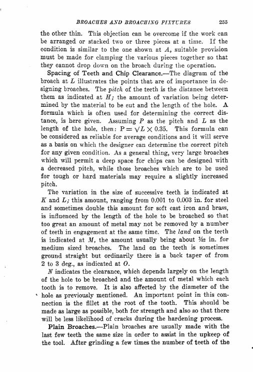
BROACHES AND BROACHING FIXTURES 255
the other thin. This objection can be overcome if the work can
be arranged or stacked two or three pieces at a time. If the
condition is similar to the one shown at A 9 suitable provision
must be made for clamping the various pieces together so that
they cannot drop down on the broach during the operation.
Spacing of Teeth and Chip Clearance. The diagram of the
broach at L illustrates the points that are of importance in de-
signing broaches. The pitch of the teeth is the distance between
them as indicated at H; the amount of variation being deter-
mined by the material to be cut and the length of the hole. Aformula which is often used for determining the correct dis-
tance, is here given. Assuming P as the pitch and L as the
length of the hole, then: P^V^XO.35. This formula can
be considered as reliable for average conditions and it will serve
as a basis on which the designer can determine the correct pitch
for any given condition. As a general thing, very large broaches
which will permit a deep space for chips can be designed with
a decreased pitch, while those broaches which are to be used
for tough or hard materials may require a slightly increased
pitch.
The variation in the size of successive teeth is indicated at
K and L; this amount, ranging from 0.001 to 0.003 in. for steel
and sometimes double this amount for soft cast Iron and brass,
is influenced by the length of the hole to be broached so that
too great an amount of metal may not be removed by a number
of teeth in engagement at the same time. The land on the teeth
is indicated at If, the amount usually being about %2 in. for
medium sized broaches. The land on the teeth is sometimes
ground straight but ordinarily there is a back taper of from
2 to 3 deg., as indicated at 0.
N indicates the clearance, which depends largely on the length
of the hole to be broached and the amount of metal which each
tooth is to remove. It is also affected by the diameter of the
hole as previously mentioned. An Important point in this con-
nection is the fillet at the root of the tooth. This should be
made as large as possible, both for strength and also so that there
will be less likelihood of cracks during the hardening process.
Plain Broaches. Plain broaches are usually made with the
last few teeth the same size in order to assist in the upkeep of
the tool. After grinding a few times the number of teeth of the
256 J108 AND FIXTURES
same size will be gradually reduced until finally there is only
one sizing tooth left, after which nothing further can be done
and the broach must be discarded or used for a smaller size
after re-grinding. Some forms of broaches can be made up in
a series of units as indicated at P, Q and B9and mounted on
an arbor 8. It is evident that the units can be provided with
a keyway for location and they can be held on the arbor by
means of check nuts as shown at T. If the size of the broach
permits, it is as well to put the nuts on the forward end and
provide a shoulder at the rear for the various cutters to be
drawn against. The size and method of coupling used have an
effect on this part of the design.
Broaching Round Holes. When round holes are to be
broached, a good finish can be given to the work by burnishing
it or swaging it as shown at J7. In this case a burnishing broach
W of rounded form is drawn up against the shouldered por-
tion V by means of the nut at X. After the cutting has been
done the rounded portion is pulled through, thus producing a
very fine finish and also compressing the metal so that a hard
wearing surface is obtained.
Broaches having considerable area often can be made to cut
more freely by nicking the teeth as shown in the diagram at Y.
The nicks must be so arranged that they overlap each other as
at Z. An arrangement of this kind breaks up the chips and
assists in cases where hard metal is encountered or on broad
surfaces.
Broach Couplings. The method of connecting the broach to
the pulling member of the broaching machine permits the opera-tion of coupling and uncoupling the broach to be done rapidly.Provision of some sort must also be made so that either the work
may be adjusted vertically in relation to the broach, or that
the broach itself can be adjusted in relation to the work. Some-times the faceplate is adjustable up and down and in other cases
the broach coupling is provided with adjustment.In Pig. 213 is shown a piece of work A and a broach B, the
latter being connected to the pulling member of the broachingmachine by means of the taper pin D.The coupling slide F is mounted on the ways of the machine
and suitably fastened to the screw E. The holder C screws
into slide G, which can be adjusted by means of screw H, so as

BROACHES AND BROACB1XG FIXTURES 257
to bring the broach into the correct position with relation to
the work.
Methods for Slotting the Ends of the Broach. The detail
at K shows a common method of slotting the end of the broach
when ?. pin coupling is used like that shown above. Anothermethod is indicated at If, this arrangement consisting of a
milled slot on each side of the bar. There are occasional in-
stances when it is desirable to pull more than one broach at a
time in a horizontal plane and when this becomes necessary it
is obvious that some other form of coupling must be used. Acase in point is shown at the lower left-hand corner of the illus-
fff Machine''
Fig. 213. Methods of Broach Pulling
tration, the coupling member X being mounted on the ways of
the machine at and P. The screw portion Q fits the pulling
member of the machine, while the broaches are held in the usual
manner at R and 8. In such a case care must be taken by the
designer to see that the pulling action is distributed equally on
both broaches so that there will be no chance of cramping dur-
ing the operation.
Keyway Broaching. Several examples of keyway broaching
are shown in Fig. 214. The ordinary method is illustrated in
the example A, which is being cut by broach D. The work is
located on a bushing B which is fastened into the faceplate of
the machine. This bushing is so made that the broach fits a slot
in it at C, thereby guiding and supporting it at the same time.

258 JIGS AND FIXTURES
This method is generally used for ordinary keyway cuttting as
the only fixture required is the guide bushing. Standard
broaches can also be used, which is obviously economical.
When a taper hole has a keyway cut in it as shown at E, the
method used is the same except, that the guide bushing F is
made to fit the taper and it is also tilted so that the keyway
will be parallel to the side of the tapered hole as indicated.
Care must be taken by the designer to see that the work fits the
tapered portion E yet does not strike against the surface G.
Sufficient clearance must be provided so that there will be no
Double Keyway
Fig. 214. Various Methods of Broaching Keyways
chance for this to happen; %e or even % in. is none too much,
depending on the angularity of the taper.
An excellent idea which can be applied to certain kinds of
work is shown at P. This is a guide bushing in which the broach
Q is operating. It is evident that as the broach or bushing
wears, the keyway will become shallower and eventually will
not be deep enough to pass inspection. By providing a shim
at R, adjustments can be made as desired by placing paper or
thin metal between the shim and the body of the bushing, thus
raising it up and prolonging its usefulness.
Referring to the work shown at L, attention is called to the
two keyways at 11 and N. In broaching a piece of work like
this two methods are possible ;a bushing can be made like that
at and two separate broaches used at M and N, in connection

BROACHES AND BROACHING 259
with a coupling; like the one illustrated in Fig. 213, or a broach-
ing bar can be made up with two inserted broaches in their
correct positions, and the work done without resorting to a guide
bushing. Either of these methods will produce good work.
Broaching Square Holes. In broaching square holes the
work must first be prepared for the operation by drilling a hole
and facing one side square with the hole. As a general thingthe corners are not quite square, as a sharp corner would be
hard to keep up and also it might cause trouble in hardening
Fig. 215. BroacMng Square Holes
if the work were to be heat-treated. The sides of the hole are
also relieved slightly in order to obtain a better bearing on the
shaft and likewise to relieve the cut somewhat while broaching.
This is clearly shown in the work A in Pig. 215. Starting with
the hole at B, the work when about half finished would appear
like the diagram at C. The illustrations at D and E show the
general form of broach used for this kind of work. The method
used for setting up the work is the same as those mentioned and
shown under the descriptions of broaches which do not require
guide bushings.
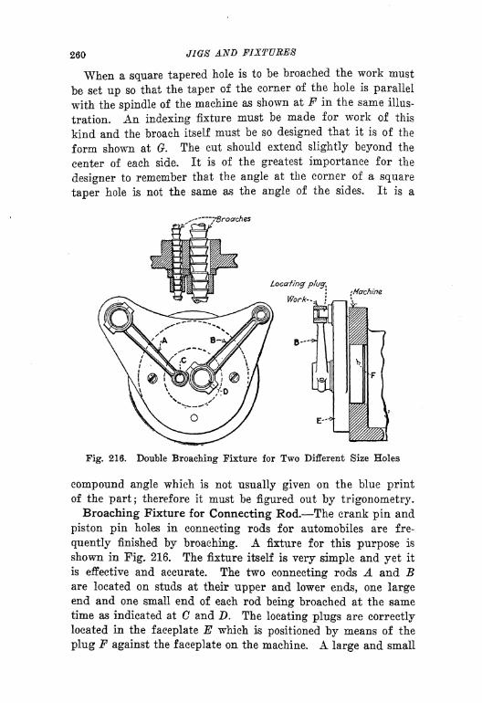
260 JIGS AND FIXTURES
When a square tapered hole is to be broached the work must
be set up so that the taper of the corner of the hole is parallel
with the spindle of the machine as shown at F in the same illus-
tration. An indexing fixture must be made for work of this
kind and the broach itself must be so designed that it is of the
form shown at G. The cut should extend slightly beyond the
center of each side. It is of the greatest importance for the
designer to remember that the angle at the corner of a square
taper hole is not the same as the angle of the sides. It is a
-- -/Broaches
Fig. 216. Double Broaching Fixture for Two Different Size Holes
compound angle which is not usually given on the blue printof the part; therefore it must be figured out by trigonometry.
Broaching Fixture for Connecting Rod. The crank pin and
piston pin holes in connecting rods for automobiles are fre-
quently finished by broaching. A fixture for this purpose is
shown in Fig. 216. The fixture itself is very simple and yet it
is effective and accurate. The two connecting rods A and Bare located on studs at their upper and lower ends, one largeend and one small end of each rod being broached at the sametime as indicated at C and D. The locating plugs are correctly
located in the faceplate E which is positioned by means of the
plug F against the faceplate on the machine. A large and small

T
BROACHES AND BROACHING FIXTURES 261
broach are used simultaneously, after which the connecting rods
are transposed while the other two holes are broached.
Broaching Fixture for a Ratchet Sector. Fixtures for
broaching use many of the devices which have been previously
illustrated and the principles of holding and clamping can be
Fig. 217. Broaching Fixture for Ratchet Sector
applied to this type of fixtures as well as to the others. There
are, however, peculiar conditions to be met in the design of
fixtures for broaching and these can best be appreciated by citing
suitable examples. The matter of removing and replacing the
broach after each operation sometimes takes time which can be
avoided by a little thought on the part of the designer. An
example of this kind is given in Fig. 217, the work A being a
262 JIGS AXD FIXTURES
ratchet sector of which four pieces are to be broached at a time
as indicated. The work is set up in the swinging locater Bwhich rests on a lug 0, and is pivoted at D in such a way that
it can be swung over into the broaching position when desired
and located by a pin at F which corresponds to G on the face-
plate as shown. In the loading position, the clamp is pulled
back as shown by the dotted lines at K while the work is being
placed on the two pins at X and Y. The clamp is then tight-
ened and the work is ready to be swung into place when the
other pieces are finished. While the loading of one group of
pieces is proceeding the other set is being machined, being held
in the other swinging member G and located by the dowel pin
at H. The clamp L holds the f6ur pieces firmly and the broach
M cuts the serrations shown. A bracket N is mounted on the
face of the plate to act as a guide and support for the broach.
After the pieces have been machined the swinging member C is
turned over until it rests on lug P where the pieces can be re-
moved and replaced by others.
As the broach used for this operation is a heavy one it is ad-
visable to support the outer end on the sliding support which
can be obtained as a part of the broaching machine equipment."With a fixture like the one shown, however, it is unnecessaryto remove the broach at all and consequently the only time lost
is in the return stroke of the broach and the swinging into placeof a fresh group of pieces. Arrangements of this kind are some-
times possible when work does not have a hole in it throughwhich the broach must pass.
Broaching Fixture for Timing Gear. Certain kinds of workmust be located in a fixed relation to each other when they are
installed in the mechanism of which they form a part. It is
therefore a decided advantage to take this into consideration
when designing tools for these parts. An example of this kindis given in Fig. 218, the work A and B consisting of two auto-
mobile timing gears. A definite relation must be kept betweenthe keyways which are to be broached and the teeth which havebeen previously cut In addition to this each gear must be
properly marked in a particular place so that when the two
gears are assembled in the car the gears can be meshed at these
points, thus assuring the correct position of the cams on the
camshaft in relation to the throws of the crankshaft
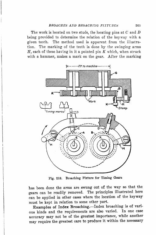
BROACHES AND BROACHING FIXTURE!* 263
The work is located on two studs, the locating pins at C and Dbeing provided to determine the relation of the keyway with a
given tooth. The method used is apparent from the illustra-
tion. The marking of the teeth is done by the swinging arms
H, each of these having in it a pointed pin K which, when struck
with a hammer, makes a mark on the gear. After the marking
Fig. 218. Broaching Fixture for Timing Gears
has been done the arms are swung out of the way so that the
gears can be readily removed. The principles illustrated here
can be applied in other cases where the location of the keyway
must be kept in relation to some other part.
Examples of Index Broaching. Index broaching is of vari-
ous kinds and the requirements are also varied. In one case
accuracy may not be of the greatest importance, while another
may require the greatest care to produce it within the necessary

264 JIGS AND FIXTURES
limits. These points must be considered when designing fixtures
for any kind of an operation. So far as the fixtures are con-
cerned the indexing devices which have been described in pre
vious articles cover the situation quite thoroughly, so there is
no necessity for repetition. Several examples of work which
may require an indexing device of some kind are shown in Fig.
219. The work A, for example, is of such large diameter that
Finished Work
Fig. 219. Examples of Index Broaching
it would hardly be desirable to make up a four spline broach,
both on account of its weight and also the expense. It is evi-
dent therefore that an indexing device would be of assistance
in a case of this kind. A method is illustrated in order to point
out the errors into which a tool designer may fall unless he
analyzes a situation carefully. Let us assume that the work is
set up on a guide bushing so that a broach can be used as at F.
If then the guide bushing has a slot G located at 90 deg. fromthe one which is used as a guide for the broach, it would appearthat the work could be turned around on the bushing to take
another position and located with a plug as at K. Witt this
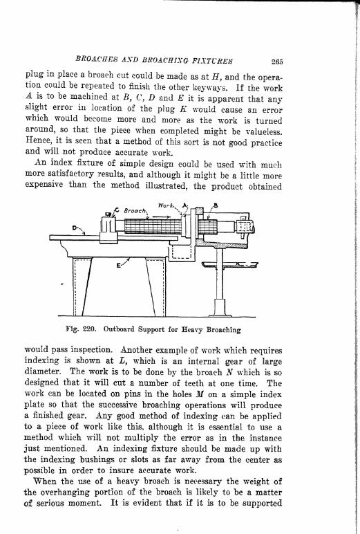
BROACHES AXD BROACHISO FIXTURES 265
plug in place a broach cut could be made as at H, and the opera-tion could be repeated to finish the other keyways. If the workA is to be machined at E
9 C, D and E it is apparent that anyslight error in location of the plug K would cause an errorwhich would become more and more as the work is turned
around, so that the piece when completed might be valueless.
Hence, it is seen that a method of this sort is not good practiceand will not produce accurate work.An index fixture of simple design could be used with much
more satisfactory results, and although it might be a little moreexpensive than the method illustrated, the product obtained
Fig. 220. Outboard Support for Heavy Broaching
would pass inspection. Another example of work which requires
indexing is shown at L, wrhieh is an internal gear of largediameter. The work is to be done by the broach N which is so
designed that it will cut a number of teeth at one time. Thework can be located on pins in the holes M on a simple index
plate so that the successive broaching operations will producea finished gear. Any good method of indexing can be appliedto a piece of work like this, although it is essential to use a
method which will not multiply the error as in the instance
just mentioned. An indexing fixture should be made up with
the indexing bushings or slots as far away from the center as
possible in order to insure accurate work.
When the use of a heavy broach is necessary the weight of
the overhanging portion of the broach is likely to be a matter
of serious moment. It is evident that if it is to be supported
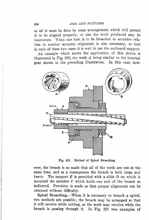
266 MG8 AND FIXTURES
at all it must be done by some arrangement whieh will permit
it to be aligned properly, or else the work produced may be
inaccurate. When one hole is to be broached in accurate rela-
tion to another accurate alignment is also necessary, so that
in each of these two cases it is well to" use the outboard support.
An example which shows the application of this device is
illustrated in Fig. 220?the work A being similar to the internal
gear shown in the preceding illustration. In this case, how-
Broach
Fig. 221. Method of Spiral Broaching
ever, the broach is so made that all of the teeth are cut at the
same time, and as a consequence the broach is both large and
heavy. The support E is provided with a slide D on which is
mounted the member C which holds one end of the broach as
indicated. Provision is made so that proper alignment can be
obtained without difficulty.
Spiral Broaching. When it is necessary to broach a spiral,
two methods are possible; the broach may be arranged so that
it will revolve while cutting, or the work may revolve while the
broach is passing through it. In Pig. 221 two examples of

BROACHES AND BROACHING FIXTURES 267
spiral work are shown at A and B and one method of broachingis shown. The work A is mounted on the broach C so that the
pulling action comes against the face of the bushing E. This
bushing is adjusted by the two check nuts at G so that it will
revolve freely and all of the thrust is taken on the thrust "bear-
ing F. The fixture D is mounted on the faceplate of the ma-
chine and fastened by means of screws.
In operation the angularity of the broach teeth causes the
work to revolve so that the spiral is cut without other assistance.

CHAPTER XI
DESIGN OF RIVETING FIXTURES
EIVETING MACHINES TYPES OF RIVETS LOCATING AND CLAMP-
US^ USE OF TABLES RING-STAKING TOOLS AND FIXTURES-
EJECTORS.
The process of riveting is used extensively in many classes of
work, both small and large. For example, adding machines,
typewriters, cash registers, etc., have many small parts made upfrom two or more units, assembled and riveted together to make
a single component of the mechanism. Automobile frames, steel
girders for buildings, ship plates, bridges and many other forms
of structural work depend largely on the process of riveting to
locate and hold together the various structural members. Rivets
in structural work are usually heated before driving but for
small parts cold rivets are used and it is here that riveting
fixtures are used to advantage.
Methods of Riveting. Rivets are headed over either by hand
or machine. In some cases the rivets are in such a position that
it is very difficult to head them over on a machine, necessitating
a hand operation. Hand riveting as a rule does not require a
fixture.
The machines used for riveting are of two general types, one
of which heads the rivet by spinning the metal over to form a
head; the other peins the metal by striking successive blows.
Both types are extensively used, the selection being dependent
upon the kind of work that is to be done.
Riveting machines are made in several styles, both horizontal
and vertical; single, double and multiple spindle ; operated me-
chanically or by pneumatic power. In some machines work is
placed on an anvil and the spindle is moved up to it; in others
the anvil itself moves toward the spindle. In the reciprocating
type of machine the spindle is arranged to hold a pein of suit-
able form, while in the rivet spinning machine hardened rolls
268

N OF RIVETIXG FIXTURES 269
are used. In either machine the action is very rapid and work
is produced much more quickly than by hand riveting1
.
Machine riveting produces sharp, quick blows which are ren-
dered elastic by springs or rubber cushions. In the pneumatic
type the air acts as a cushion. The force of the blow can be
regulated by the operator. The application of riveting fixtures
covers such a wide field that it will be understood better by re-
ferring to the various examples given in this article. The facility
with which work can be handled generally governs the produc-
tion, as the actual time consumed by the riveting operation is
very small.
The kind of work to be riveted affects the shape and form of
Toper I** Oper Toper 2!? Oper
Tl Blind Rivet
Straight- l^Oper Straight- 2" Oper.
Fig. 222. Types of Rivets and Riveting
rivets used. Straight rivets with round heads are often used
when the appearance is important and when there is plenty of
room in the mechanism so that projecting rivet heads will not
interfere with some other part. Straight rivets with flat or
countersunk heads are also much used for plain work. Taper
rivets are valuable when correct relation of several parts to each
other is required.
Fig. 222 shows several types of rivets and methods of riveting.
Pieces A, B and C are to be riveted together with taper rivets
as shown at D. Before the riveting operation the parts are
reamed in a locating jig and rivets are inserted to act as dowels
and keep the parts together. The form of locating jig men-
tioned has been described under the head of drill jig design.
In riveting these parts together a taper rivet D is used. The

270 JIGS AND FIXTURES
first operation heads over the large end of the rivet and it is
important that clearance should be provided in the riveting
fixture at E so that the rivet will not bottom. After the large
end has been headed the work is turned over so that the small
end comes uppermost as at G. The other head of the rivet rests
on the anvil at F. Care must be taken to see that work does
not rest on the block in this ease as the rivet head might be
somewhat lower than the surface of the work which would allow
it to be forced out during the riveting process. This would
cause a loose fitting rivet and inaccurate work. It is important
that taper rivets should be made of uniform length and the
holes must always be carefully reamed.
Straight Riveting. When straight rivets are used in fasten-
ing several pieces together as shown at H, K and L, the anvil
used must be cut away to allow the end of the rivet to seat itself
as shown at N. The depth of the recess should be sufficient to
allow for a head on this end of the rivet when the work is
turned over. After the head M has been formed the work is
reversed and the head takes the position 0. The other end Ncan then be riveted taking care that the head rests firmly on
the anvil.
Round Head Rivets. This is the most common type of rivet-
ing, as the rivet is always provided with one head. This head
rests in a special anvil E which is cupped at 8 deeper than the
rivet head and slightly smaller in diameter. This supports the
rivet and also prevents it from turning. Riveting of this kind
is often done on a punch press as well as a riveting machine
and several rivets may be headed at the same time, providingthe work is uniform.
Blind Rivets. When rivets do not go through the piece of
work they are called blind rivets and are generally made in
taper form as shown at U. When a case of this kind is found,
the taper of the hole should be slightly different from that of
the rivet in order that a wedging action will be produced due
to the difference between the two tapers. This wedging action
is sufficient to hold the rivet in place.
Method of Riveting Rollers. If a roller such as that shownat C in Fig. 223 is to be held in place in a piece of work A bymeans of the special rivet B, provision must be made so that
the roller will be free to move on the rivet. Suitable allowance
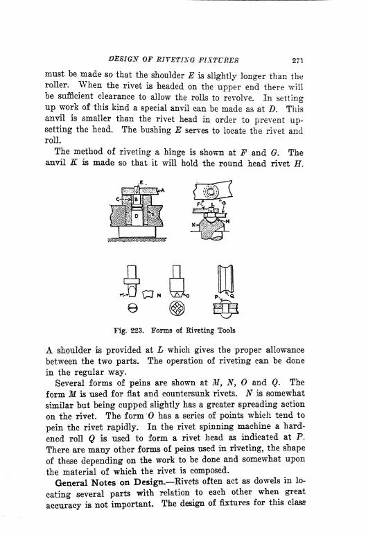
DESIGN OF RIVETING FIXTURES 271
must be made so that the shoulder E is slightly longer than theroller. When the rivet is headed on the upper end there will
be sufficient clearance to allow the rolls to revolve. In setting
up work of this kind a special anvil can be made as at Z>. Thisanvil is smaller than the rivet head in order to prevent up-setting the head. The bushing E serves to locate the rivet androll.
The method of riveting a hinge is shown at F and G. Theanvil K is made so that it wiH hold the round head rivet H.
n
N \ZiAo
Fig. 223. Forms of Riveting Tools
A shoulder is provided at L which gives the proper allowance
between the two parts. The operation of riveting can be done
in the regular way.
Several forms of peins are shown at M, N, and <?. The
form M is used for flat and countersunk rivets. N is somewhat
similar but being cupped slightly has a greater spreading action
on the rivet. The form has a series of points which tend to
pein the rivet rapidly. In the rivet spinning machine a hard-
ened roll Q is used to form a rivet head as indicated at P.
There are many other forms of peins used in riveting, the shape
of these depending on the work to be done and somewhat upon
the material of which the rivet is composed.
General Notes on Design. Rivets often act as dowels in lo-
cating several parts with relation to each other when great
accuracy is not important. The design of fixtures for this class

272 JW8 AND FIXTURES
of work is not at all difficult. "Work having a center hole and
in which rivets are located radially should be provided with a
location hole unless the shape of the piece is such that it can
be easily set up in the desired position. For instance, if two
washers are to be riveted together so that the center holes will
be in alignment, a stud can be used as a locater; whereas if the
outside diameters are to be in alignment the work should be
nested and located from the outside. In riveting two gears to-
gether so that the teeth will bear a certain relation to each other,
pins or pawls should be used between the teeth.
The location points for work that is to be riveted should be
as near to the outside as possible, in order to obtain maximum,
accuracy. Clamps are not always required in riveting work
together but they are frequently used in order to prevent
spreading of the work when the pressure of the hammer is ap-
plied. A rivet spread out between two pieces of work is the
ordinary result unless clamps are used, the vibration of the
machine causing the two pieces to separate. Various types of
rivets require special forms of anvils in order to avoid the pos-
sibility of bad rivets. Several points in this connection have
been brought out in Figs. 222 and 223.
The position and location of the fixture on the riveting table
must be so arranged that the rivet will *be directly over the
anvil and in contact with it. The production required on any
riveting proposition does not necessarily affect the design of the
fixture as there are not many ways of riveting work. Positive
and rapid clamping are important, however, and the accuracy of
the product is dependent upon the location and the use of properrivets.
Vibration should always be considered. All loose parts of
fixtures should be well screwed down so that the excessive vibra-
tion cannot loosen them and cause trouble.
.Riveting Several Pieces Together. In Fig. 224 is illus-
trated a method for locating and clamping several pieces to-
gether for riveting. This is an example which makes plainthe importance of proper locating and clamping, in order to
prevent trouble due to vibration and also to insure accuracy.Unless the work is held properly it is likely to open upand separate so that the rivet may bulge out as shown at Cbetween the plates A and B. Rivets should not be used as
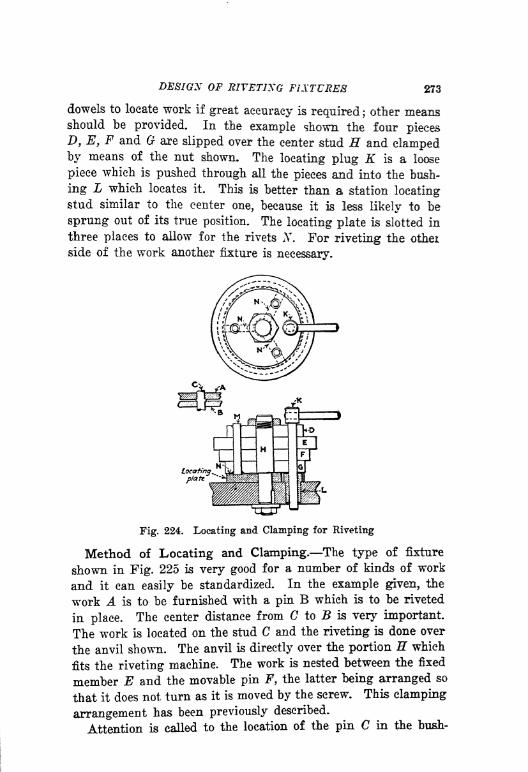
DESIGN OF RIVETING FIXTURES 273
dowels to locate work If great accuracy Is required ;other means
should be provided. In the example shown the four pieces
D, E, F and G are slipped over the center stud H and clampedby means of the nut shown. The locating plug K Is a loose
piece which is pushed through all the pieces and Into the bush-
ing L which locates It. This is better than a station locatingstud similar to the center one, because it is less likely to be
sprung out of its true position. The locating plate is slotted in
three places to allow for the rivets N. For riveting the othei
side of the work another fixture is necessary.
Fig. 224. Locating and Clamping for Riveting
Method of Locating and Clamping. The type of fixture
shown in Fig. 225 is very good for a number of kinds of work
and it can easily be standardized. In the example given, the
work A is to be furnished with a pin B which Is to be riveted
in place. The center distance from G to B is very important.
The work is located on the stud C and the riveting is done over
the anvil shown. The anvil is directly over the portion H which
fits the riveting machine. The work is nested between the fixed
member E and the movable pin F, the latter being arranged so
that it does not turn as it is moved by the screw. This clamping
arrangement has been previously described.
Attention is called to the location of the pin C in the bush-
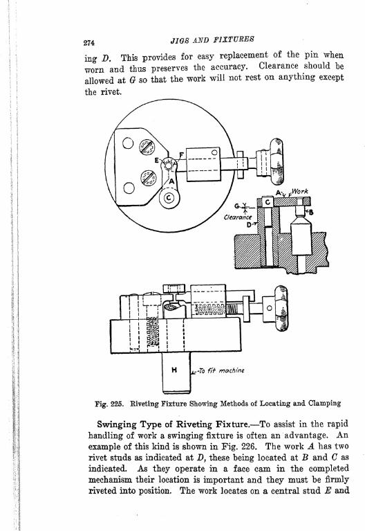
274 JIGS FIXTURES
ing D. This provides for easy replacement of the pin when
worn and thus preserves the accuracy. Clearance should be
allowed at G so that the work will not rest on anything except
the rivet.
Tig. 225. Riveting Fixture Showing Methods of Locating and Clamping
Swinging Type of Riveting Fixture. To assist in the rapid
handling of work a swinging fixture is often an advantage. An
example of this kind is shown in Fig. 226. The work A has two
rivet studs as indicated at D, these being located at B and C as
indicated. As they operate in a face cam in the completedmechanism their location is important and they must be firmly
riveted into position. The work locates on a central stud E and

DEFIGN OF RIVETING FUTURES 275
is held firmly in position by the pawl F operated by the thumb-
screw G. The swinging member of the fixture is pivoted at //
so that in operation the rivets can be brought into position
under the hammer by swinging the lever I/ until it strikes the
pins at K and L. When in the riveting position ample support
Fig. 226. Swinging Type Riveting Fixture for Two Holes
is given by the fixture at N, this portion being clamped in place
in the riveting machine. The dotted lines indicate the two posi-
tions of the fixture when riveting. This is a clean cut example
of a simple riveting fixture involving principles which can be
applied to other work of similar character. Tables axe^
often
used on riveting machines in order to simplify the location of
fixtures which are to be used for several operations. Also when

276 JIGS AND FIXTURES
fixtures are large and when rivets are so spaced that they can-
not easily be located on an anvil, a table permits easy location
and makes the operation of riveting more convenient. A few
points in connection with the use of tables are illustrated in
Fig. 227. It is important that the table should be so located
that the stem A will be in positive contact with the anvil on
the machine. There must never be a space between them as
indicated at B as this would not give proper support. The
Locating pfnS"
tTurn fixture 180
* fbr this hole
O
.Table
JUL Uw&M.Tcrb/e Anvif
l_
'%%%%0^///W/////^^^ Anvil"*
Fig. 227. Use of Special Table with Locating Pins
fixture which may have an anvil of its own, must also alwaysbe made so that the under side of the anvil is in contact as at
C. It should never be made as shown at D as this would not
give good results and would buckle as indicated by the dotted
line.
In locating any fixture on the table an arrangement of pinscan be provided so that several locations can be easily made.
If a number of pieces of a similar kind are to be riveted it is
often possible to standardize the tables and the relation of the
pins so that fixtures can be built which will all be usable on the
same table. The work E for example is to be riveted at F, G
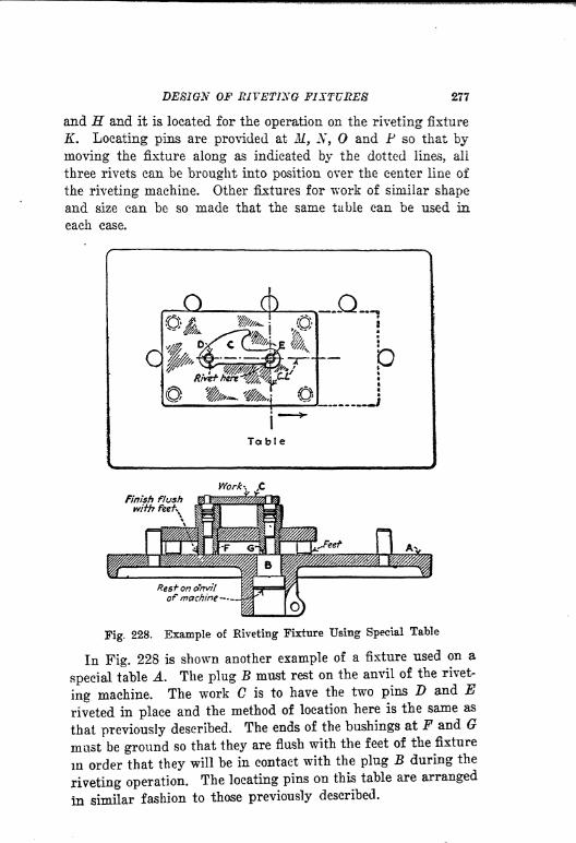
DESIGN OF RIVETING FUTURES 277
and H and it is located for the operation on the riveting fixture
K. Locating pins are provided at M 9 N, and P so that by
moving the fixture along as indicated by the dotted lines, all
three rivets can be brought into position over the center line of
the riveting machine. Other fixtures for work of similar shape
and size can be so made that the same table can be used in
each case.
Table
Finish flushwith feef*
Work*. ,C
Fig. 228. Example of Riveting Fixture Using Special Table
In Fig. 228 is shown another example of a fixture used on a
special table A. The plug B must rest on the anvil of the rivet-
ing machine. The work C is to have the two pins D and Eriveted in place and the method of location here is the same as
that previously described. The ends of the bushings at F and G
must be ground so that they are flush with the feet of the fixture
in order that they will be in contact with the plug E during the
riveting operation. The locating pins on this table are arranged
in similar fashion to those previously described.

278 JIGS AND FIXTURES
Riveting Fixture Used for Both Sides of Work. The de-
signing department can often help in simplifying the design of
riveting fixtures by paying attention to the location of rivet
holes, and placing them in such positions that the same fixture
can be used for riveting both sides of the work. An examplewhich illustrates the advantages of this forethought is shown
Table,
Fig. 229. Riveting Fixture for Both Sides
in Fig. 229. The pieces A and B are riveted together at three
points C, D and E, these points being 120 deg. apart and thesame distance from the center. The pieces are assembled onthe center plug at F, resting on six plugs as indicated. Threeof these plugs are cut away to allow for the heads of the rivets,while the other three are plain on the top. For the first rivetingoperation the slotted pins are used successively; but for thesecond the plain pins are used, the work being turned over.Two pins G and H are used in the riveting machine table to

DESIGN OF RIVETING FIXTURES 27S
act as locaters for the fixture. It will be noted that the edge of
the fixture is notched in several positions so as to give correct
locations for the various rivets. The notch acts as one locater
against the pin H, while the other location is fixed by a contact
Locating-'
pins
Section A-B-C-D -E
Fig. 230. Riveting Fixture for Two Spur Gears
of the outside of the fixture with the pin G. A pin L is placed
in the fixture to locate the two pieces and attention is called to
the manner in which it is cut away so that it will not interfere
with the flange indicated. All of the six studs used for riveting
are flush with the legs of the fixture thus assuring proper sup-
port when they are brought into position for riveting. This
fixture is built high in order to make it easier to turn over; it is
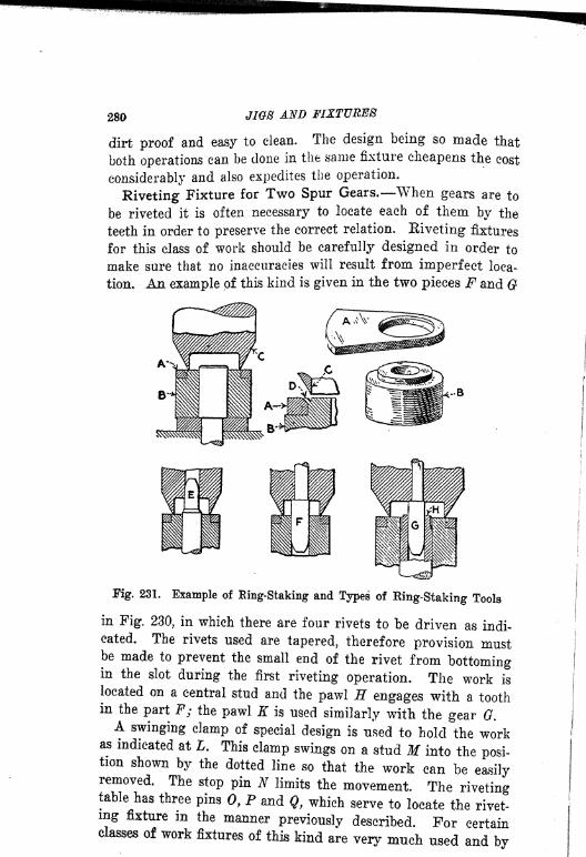
280 JIG8 AND FIXTURES
dirt proof and easy to clean. The design being so made that
both operations can be done in the same fixture cheapens the cost
considerably and also expedites the operation.
Riveting Fixture for Two Spur Gears, When gears are to
be riveted it is often necessary to locate each of them by the
teeth in order to preserve the correct relation. Riveting fixtures
for this class of work should be carefully designed in order to
make sure that no inaccuracies will result from imperfect loca-
tion. An example of this kind is given in the two pieces F and G
Fig. 231. Example of Ring-Staking and Types of Ring-Staking Tools
in Fig. 230, in which there are four rivets to be driven as indi-cated. The rivets used are tapered, therefore provision mustbe made to prevent the small end of the rivet from bottomingin the slot during the first riveting operation. The work is
located on a central stud and the pawl H engages with a toothin the part F; the pawl K is used similarly with the gear 0.A swinging clamp of special design is used to hold the work
as indicated at L. This clamp swings on a stud M into the posi-tion shown by the dotted line so that the work can be easilyremoved. The stop pin N limits the movement. The rivetingtable has three pins 0, P and Q, which serve to locate the rivet-ing fixture m the manner previously described. For certainclasses of work fixtures of this kind are very much used and by
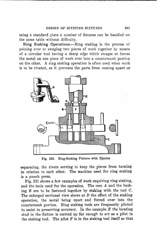
DESIGN OF RIVETING FIXTURES 281
using a standard plate a number of fixtures can be handled on
the same table without difficulty.
Ring Staking Operations. Ring staking is the process of
peining over or swaging two pieces of work together by means
of a circular tool having a sharp edge which swages or forces
the metal on one piece of work over into a countersunk portion
on the other. A ring staking operation is often used when work
is to be riveted, as it prevents the parts from coming apart or
Fig. 232. Ring-Staking Fixture with Ejector
separating, the rivets serving to keep the pieces from turning
in relation to each other. The machine used for ring staking
is a punch press.
Fig. 231 shows a few examples of work requiring ring staking,
and the tools used for the operation. The cam A and the bush-
ing B are to be fastened together by staking with the tool C.
The enlarged sectional view shows at D the effect of the staking
operation, the metal being upset and forced over into the
countersunk portion. King staking tools are frequently piloted
to assist in preserving accuracy. In the example E the locating
stud in the fixture is carried up far enough to act as a pilot in
the staking tool. The pilot F is in the staking tool itself so that

282 JIGS AND FIXTURES
it centers the work as it enters the hole. In another example
the pilot G in the staking tool enters a bushing on which the
work locates, the bushing being relieved slightly at H so that if
the metal is contracted by the staking tool it can still be removed
from the bushing without difficulty.
Ring Staking Fixture with Ejectors. Fig. 232 shows a com-
plete fixture for ring staking the two parts A and B. The fixture
fits in a shoe C on the bed of the punch press, being located
and held in place in some approved manner. The counterbored
portion of the shoe D can be standardized so that a number of
fixtures can be used with the same shoe. The staking tool Efits the ram of the punch press as indicated. The work locates
on a stud F which extends above it and acts as a pilot for the
tool.
Work of this kind sometimes clings to the tool and rises with
it, in which case a stripper like that shown at G may be found
an advantage. Work may also stick on the locating plug so
that it is not easily removed without using an ejector. It is
advisable to provide for both contingencies by using both
stripper and ejector. The form of ejector used in this instance
has been previously described so that further comment is un-
necessary. It is important to know the stroke of the press when
designing ring staking fixtures, in order that the height oif the
fixtures may be kept within the required limits.

INDEX
Accuracy in milling operations,
importance of, 152
of vise-jaws, 234
required, consideration of, 4
Accurate work, four-sided jig for
obtaining, 108
Adjustable jacks, 51
v-blocks, 53
Advantages of duplex milling, 188
Air operated clamps, 180
pressure for cleaning fixtures, 28
Aluminum jig leaves, 59
Analysis, value of, in laying out
operations, 18
Angle iron jig bodies, 62
Angular and straight holes, drill
jigs for, 92
holes, drill jig for, 92
index fixture for drilling, 117
plates, use of, 107
work, method of drilling, 107
Applications of milling cutters, 145,
147
of step blocks to profiling
fixtures, 221
Assembling and locating jigs, 97
Attachment for form milling, 184
Automatic cam cutting machines,216
form milling attachment, 184
indexing, device for hand mill-
ing machine, 201
for milling, 200
drill jig, 114
jig, 122
profiling, 227
fixtures for, 227
B
Bearing seats, importance of con-
centricity in, 6
Bearings for jig leaves, 57
Beeswax vise-jaws, 241
Bench milling machines, various
types of, 136
Blind rivets, 270
Boring and reaming index jig, 105
Box or closed jigs, 36
Brake band, indexing jig for, 120
Broach couplings, 256
fixture, double, 260
pulling, methods of, 257
slotting for coupling, 257
supporting and aligning, 265
Broaches and broaching fixtures, 247
important points in design
of, 247
chip clearance for, 255
design of, 257
important points in design of,
254
lubrication of, 249
spacing of teeth in, 254H255
Broaching an oil groove, simplemethod of, 251
examples of work suitable for,
252
fixture cost of, 249
double, 263
for connecting rod, 260
for ratchet sector, 261
for timing gear, 262
with locaters, 263
fixtures and broaches, 247
clamping methods used in, 249
important points in design
of, 247
rigidity of, 249
importance of outboard support
in, 265
important points in design of
fixtures for, 248
index, 264
keyways, methods used in, 258
283

284 INDEX
Broaching, methods of, 250
of setting up for, 252
plain, 252, 253
principles of, 248
round holes, 256
spiral, method of, 266
square holes, 259
tapered holes, 260
types of, 250
Bronze casting, continuous circular
milling fixture for, 210
ring, milling fixture for cutting,
197
Built up jigs, 37, 96
Burr clearance in drill jigs, 32
Bushing design, 73
Bushings, insufficient clearance for,
16
design and proportion of, 72
knurled, 71
liner, 72
location of, 75
methods of holding, 74
screw, 71
slip, 71, 74
types of, 71
Button clamps, 44
Cam clamp for shaft, 89
cutting machines, 216
drum trunnion jig, 128
lever method of locking jig
leaves, 60
Cast iron angle jigs, 64
Castellating nuts, index fixture for,
196
Castings, finished, location of, 25
thin, method of supporting and
clamping, 177
Channel iron jig bodies, 62
Chart of inserted tooth milling
cutters with solid bodies,
150
Chatter in milling fixtures, 152
Chip clearance in closed jigs, im-
portance of, 90
in drilling, 30
Chip troubles in drilling, 32
in milling fixtures, 156
Chips in milling fixtures, 153
provision for, 153, 157
for washing out, 28
Chuck jaws, serrating fixtures
for, 207
Chucking lugs added to casting, 5
stem, advantage of, 15
Circular profiling, 223
Clamp, cam operated, 89
for holding and locating work
in jig, 49
in leaf of closed drill jig, 91
plain, s'mple type of, 41
Clamping, correct, 47
correct and incorrect, 27
importance of, 40
improper, distortion caused by,
26
incorrect, 47
pneumatic, 180
pressure, direction of, 25
suggestions for, 44
thin castings, method of, 177
work, correct and incorrect
methods of, 41
work in groups, 173
Clamps, air operated, 180
button, 44
double end, 47
equalizing, 44, 47
air operated, 180, 181
principles of, 48
for milling, equalizing, 171
special forms of, 166, 167
hook-bolt, 174, 176
in jig leaf, 58
in the leaf, 57
knife edge, 170
lever, 44
operated, 168
multiple, 46
for milling, 172
operated by lever, 168
pivot, 44
representative group of, 44
sliding, 44
used in milling, 165

INDEX 285
Clamps, wedge, 42
Cleaning, provision for jig, 28Clearance around work, importance
of, 27
for burrs in drilling, 32for chips in drilling, 30for operator's hand, 77
when indexing jigs, 103
Closed drill jigs, 91
jigs, simple type, 94
with clamp in leaf, 91
or box jigs, 36
Clutch drum, indexing jig for, 121
Combined index and latch for
drill jig, 114
Concentricity, importance of, 6
Connecting link, spline milling
fixture for, 191
rod broaching fixture, 260
forgings, location for drilling,
23
index fixture for miling, 202
Consecutive operations in vise-jaws,
240
Construction details of milling
fixtures, 158
of jig leaves, 57
of leaves in drill jigs, 56
Continuous circular milling fixture
for bronze casting, 210
milling fixture for chuck jaws,
207
for cylinder heads, 206
for pump body, 209
fixtures, principles of, 205
machine, diagram of, 141
method of locating work
economically for, 205
special machines for, 212
slot and straddle milling fixture,
208
Correct and incorrect methods of
drilling holes in adjacent
parts, 26
Cotter pin jigs, 32
Couplings for broaches, 256
Cradle trunnion jig, 126
Cup bushings, location of work in,
22
Cutter action, diagram showing, 154
in relation to clamps, diagramillustrating, 155
on the work, 154
teeth, action of, 155
Cutters, milling, action on work, 154
inserted teeth with staggered
blades, 149
sizing chart of, 148
standard straight side in-
serted tooth, 151
Cylinder heads, continuous millingfixture for, 206
C-washers, use of, 44
Delicate operation, profiling fixture
for, 222
Design, changes in, consideration of,
4,5, 6
of broaches, 254
of drill jigs, 18
of hook-bolts, 175
of index plungers and latches,
111
of sliding v-blocks, 54of swinging v-blocks, 55
of trunnion jigs, 124
of u-lugs, 160
Details of jig leaves, 59
of trunnions, 125
Diagram of milling . machine show-
ing dimensions ,144
Difficult casting to machine, 10
drilling problem, example of a,
131
Direction of clamping pressure, 25
Distortion caused by improper
clamping, 26
Double broach fixture, 260
broaching fixture, 263
end clamps, 47
indexing fixture for a forked
lever, 204
trunnion jig, 130
Drill bushing, insufficient clearance
for, 16
index jig for reaming and bor-
ing, 105

286INDEX
Drill jig, built up, 96
bushings, 72
design, 18
double trunnion, 130
ejectors, use of, 79
feet, casting, 68
examples of, 68
inserted, 68
method of fastening, 68
for a clutch drum, indexing,
121
for a radial rivet hole, index-
ing, 120
for annular ring, indexing, 119
for pistons, 118
for pump cover, 90
for shaft, open, 89
indexing, for holes in a circle,
116
for rapid production, 112
locating and assembling, for
shaft and collars, 98
open trunnion, 127
plate for dovetail slide, 86
roll-over, 123, 124
simple index, 109
swivel index, 106
templet, design of, 82
trunnion, for cam drum, 128
used progressively, 133
with cradle, 126
with angular plate, 107
with swinging v-block, 95
jigs, cast iron, 64
closed, 90, 91
simple type, 94
for angular and straight holes,
92
for rivet holes, 100
indexing and trunnion, 101
locating and assembling, 97
examples for practice, 99
open, 86
for lever arm bracket, 88
plate, 84
trunnion, 124
details, 125
Drilled holes close to a shoulder, 15
in forgings, 21
Drilling and reaming in same jig, 110
method of, 110
holes in adjacent parts, 26
index table for, 115
machines, spacing of, 8
problem, difficult, 131
Duplex milling, continuous millingfixture for, 211
fixtures, 188
machine, 140
diagram, 139
multiple fixture for, 189
E
Effect of design on cost of machin-
ing, 10
Ejector for a large casting, 132
used on ring staking fixture, 281
Ejectors, 79
eccentric, 80
for drill jigs, 80
for vise-jaws, 244, 245
wedge type, 80
Elementary points in design of drill
jigs, 19
Equalizing clamps, 44
for milling, 171
principles of, 48
hook-bolts, 178
milling fixture with, 179
pressure by means of beeswax
jaws, 241
vise-jaws, 244
Example of a difficult drilling
problem, 131
Examples of jig feet, 68
of shapes suitable for profiling,
224
F
Feeler, use of, in milling, 162
Feet, jig, examples of, 68
Finger jacks, 51, 171
Finished work, location of, 23
Fixture clamped in vise, 243
for use in vise-jaws, 243
Fixtures for broaching, 247
INDEX 287
Floating vise-jaws, 237
Forging, location in cup bushings, 22
Forgings, location of, 21
Form milling attachment, auto-
matic, 184
plate for profiling use, 225
Formed vise-jaws, 233
Forms of riveting tools, 271
Four-sided drill jig for accurate
work, 108
Gear blank chucking, 15
forging with countersunk
holes, 22
Guides, standard jig used between,66
H
Hand clearance, importance of, 77
knobs, 78
milling machine, automatic in-
dexing device for, 201
diagram, 137
work suitable for, 138
wheels, 78
High production straddle milling
fixture, 186
Hinges for jig leaf, 59
Holes, square, broaching, 259
Hook-bolt clamps, 42
backing up, 43
for milling, 174
special applications of, 175
Hook-bolts design of, 175
equalizing, 178
milling fixture with, 179
Importance of clamping work prop-
erly, 40
Important points in connection with
broaching, 248
Improved design of parts, 13
Improvements in machining ob-
tained by change in design,
10
Index and latch combined, 114
broaching, 264
methods of, 264
drilling and reaming, 110
fixture for angular holes, 117
for castellating nuts, 196
for connecting rod, 202for cutting bronze ring, 197
for holes in a circle, 116
head, use of, 193
jig for boring and reaming, 105
simple, 109
swivel, 106
milling fixture, twin, 195
pin, location of, 111
plungers and latches, 111, 112
table for drilling, 115
Indexing and trunnion jigs, import-ant points in, design of, 102
attachment for milling, semi-
automatic, 200
automatic device for drill jig,114
fixture, double, for connecting
rod, 202
semi-automatic, for milling
spline shaft, 198
jig, 38
for a clutch drum, 121
for annular ring, 1 19
for radial rivet holes, 120
rapid production, 122
jigs, clearance necessary for, 103
for angular holes in a piston,
118
for multiple holes in drilled
plate, 104
interferences in, 103
requirements of, 101
milling fixture, 192
machines, 143
principles and methods of, 110
requirements, 103, 104
Inserted tooth face mills, standard,
152
milling cutter chart, 149
with solid body, 150
Interfering shoulder, 17
Irregular work, locating and clamp-
ing, 169

288 INDEX
Jacks, 48
adjustable, 51
and spring plungers, 50
finger, 51, 171
locking, 51
Jig bodies, angle iron, 62
channel iron, 62
standard type, 63
boxed or closed, 36
leaf clamps, 58
construction, 57
details, 59
locking, 60
posts and thumbscrews, 67
Jigs, built up type, 37
cast iron angle, 64
indexing, 38, 101
leaf, 56
open type, 36
standard, 62
trunnion, 37
types of, 34
with rocking clamps, 65
KKerosene for cleaning, 28
Keys, design of, 162
and T-slot proportions, 161
Keyway broaching, 258
Knife edge clamps, 170
for milling, 165, 166
Knobs and thumbscrews, standard,76
hand, 78
Light work clamps, 44
Lincoln type milling machines, 139
Liner bushings, 71
Locating and assembling jigs, 97
for shaft and collars, 98
and clamping for riveting, 273
odd shaped work, 169
and holding work by clamping,49
and supportingwork for milling,164
jigs, 97
examples for practice in de-
signing, 99
pins for indexing, 112
studs, use of, 30
surfaces, wear on, 29
two spur gears for riveting, 279
Location, correct and incorrect, of
work, 27
of bushings, 75
of connecting rod forging, 23of finished work, 23
of rough forgings, 21
work, 19
of small work in vise-jaws, 239of work, 4
for riveting, 272in vise-jaws, 234, 235
pins used in riveting, 276
Locking jacks, 51
plugs, 69, 70
spring plungers in jacks, 50two jacks at one time, 52
Lubrication of broaches, 249
Lugs, chucking, 5
Large casting, ejector for, 132
Layout of plant, 7
Leaf clamps, 57
construction, 56, 59
jigs, 56
locking jig, 60
stops, 61
supports, 61
Lever clamps, 44
index milling fixture for, 204
operated clamps, 168
M
Machine tool, avoiding dead time on,152
placements, 8, 9tools available, 6
purchase of, 7
selection of, 7Machined surfaces, location of, 24Material to be considered in listing
operations, 2to be cut in milling fixtures, 153
INDEX 289
Method of clamping work, 155
of locking leaf, 59
of making locating studs, 30
Methods of bracing work, 163
of broaching, 250
of clamping work in groups, 173
of ring staking, 280
of riveting rollers, 270
Milling continuous, 205
cutters, action on work, 154
application of, 145
selection of, 144
sizing chart of, 148
special application of, 147
spline, action of, 190
standard, straight size in-
serted tooth, 151
fixture basis, design of, 158
chip troubles, 156
clamps, 165
special form, 166, 167
construction details, 158
continuous for bronze casting,
210
for chuck jaws, 207
for cylinder heads, 206
for pump body, 209
design, important points in,
151
for castellating nuts, 196
for cutting bronze ring, index,
197
piston ring, 183
for duplex milling, 188
machine, continuous, 211
for facing and splitting boss,
182
for slot, multiple under-cut,
187
hand, 182
index, for connecting rod, 202
for square shaft, 193
indexing, 192
for forked lever, 204
reciprocating, principles of,
185
set block, 153
spline for connecting link, 191
straddle, 186
Milling fixture, with equalizing
hook-bolts, 179
fixtures, design of, 157, 182
of fixture bases for, 158
details of construction, 159
multiple for duplex milling,
189
reciprocating, use of, 186
rigidity of. 152
straddle, 186
uniformity of ribs and wails
159, 160
up keep of, 153
machine diagram, continuous,141
duplex, 139
multi-spindle, 141
showing dimensions, 144
vertical, 141
duplex, 140
indexing diagram, 143
selection of, 153
vises, 2SO, 231
machines, bench, 136
diagram, Lincoln type, 139
diagrams, hand and plain, 137
indexing, 143
Lincoln type, 139
multiple spindle, work suit-
able for, 142
plain, 138
selection of, 135
types of, 134
vertical, 140
operations, accuracy required,
152
spline, 189
principles of, 147
thread, application of, 147
with hob cutter, 147
with single cutter, 147
various forms of milling cute,
146
work accurately, 162
Multi-spindle milling machine dia-
gram, 141
Multiple clamps, 46
for milling, 172
locking, 172
290 INDEX
Multiple milling, 192
fixture under-cut for slot, 187
fixtures for duplex milling,
189
spindle milling machine, work
suitable for, 142
vise-jaws, 237
Odd shaped work, locating and
clamping, 169
Oil groove broaching, 251
Open drill jig, 86
for pump cover, 90
jig type, 36
Operation sheet typical, 11
Operations, listing of, 2
Operator's safety, 153
Outboard support for broaching, 265
Peins for riveting, 271
Pinch binder slot, milling fixture for,
182
Piston, indexing jig for angular
holes, 118
ring, cutting milling fixture, 183
Pivot clamps, 44
Placement of machine tools, 8, 9
Plain clamps, 41
type of, 42
milling machine, 138
diagram, 137
machines, work suitable for,
139
Plant layout, 7
Plate and templet jigs, 35
jig for dovetail slide, 86
for large casting, 84
large, 84
jigs, 34, 84
Plugs, locating, 69
locking, 70
Plungers, spring, 48
Pneumatic clamping, 180
principles of, 180
Posts, jigs, 67
Principles and methods of indexing,110
of drill jig design, 18
of pneumatic clamping, 180
Production required in listing of
operations, 2
in milling operations, 151
Profiling, accuracy required, 217
automatic, 227
chip accumulation, 218
circular, 223
cuts, forms of, 218
various kinds of, 218
fixture, design of, 213
examples of, 222
multiple, 227
well designed, 225
fixtures, application of step
block, 221
circular, 228
design of, 217
location of work for, 217
machine, bench, diagram of, 213
machines, bench, 213one and two spindles, dia-
grams of, 215
use of, 213
position of work, 217
roughing and finishing methods
of, 226
shape of work, 217
shapes suitable for, 224
slot, 222
step, 219, 220
surfaces, 219
use of form plate, 225
Progressive use of trunnion jig, 133
Proportion of bushings, 72, 73
Proportions of u-lugs, 161
Protection for spring plungers and
jacks, 50
Pump body, continuous milling
fixture, 209cover jig, 90
Punch used with templet jig, 35
Quarter-turn screws, 67
INDEX 291
R
Ratchet sector broaching fixture, 261
Reciprocating milling fixtures, 186
principles of, 185
Removal of work from jigs, 81
Removing and setting up work, 34
Requirements for tools, 9
Ribs and walls, uniformity of, 159,
160
Rigidity of broaching fixtures, 249
of milling fixtures, 152
Ring staking, 280
fixture with ejector, 281
holes, 280
methods of, 280
operations, 281
Rivet hole, indexing jig for, 120
holes, drill jigs for, 100
Riveting fixture for several pieces,
273
for two holes, 275
spur gears, 279
on special table, 277
showing method of locating
and clamping, 274
swinging type, 275
fixtures, design of, 268
important points in design of,
272
swinging type, 274
locating and clamping for, 273
machines, 268
methods of, 268
process of, 268
rollers, method of, 270
several pieces, 273
straight, 270
table, special, 276
with locating pins, special,
276
tools, 271
work from both sides, 278
Rivets as dowels, 271
blind, 270
important points in, 272
plain, 269
round head, 270
types of, 269
Rivets, various kinds of, 269
Rocking clamps in drill jigs, 65
Roll-over jigs, 123, 124
Roll-over design for, 123
Rollers, method of riveting, 270
Rough work, location, of, 19
for a hub, 21
Round head rivets, 270
hole broaching, 256
Routing sheet, 11
S
Safety of operator, 153
Screw bushings, 71
machines, spacing of, 9
Screws, quarter turned, 67
Selection of milling cutters, 144
machines, 135, 153
Semi-automatic indexing device for
milling, 200
Serrating fixture for chuck jaws, 207
Set blocks, 162
on milling fixtures, 153
Set-on or plate jigs, 34
Setting up and removing work ?34
work from hub, 21
Shoulder, drilled holes close to, 15
Simple leaf jig, 56
Size of drilled holes, 33
Sliding clamps, 44
for milling, 165
trunnion jig, 129
v-blocks, 53, 54
Slip bushings, 71
methods of holding, 73
Slot and straddle miling fixture,
continuous, 208
milling fixture, multiple or
under-cut, 187
profiling, 222
Small work, vise-jaw fixture for, 243
Solid body, inserted tooth milling
cutter, 150
Special applications of hook-bolt
clamps, 175
machines for continuous mill-
ing, 212
table with riveting fixture, 277
292 INDEX
Spider support for milling, 178
supporting jack, 178
Spiral broaching, methods used for,
266
Spline and slot milling, explanatory-
diagram, 190
nulling, 189
action of cutters, 190
fixture for connecting link,
191
principles of, 147
Splined shaft, semi-automatic index-
ing fixture, 198
Spring plungers, 48
and jacks, 50
v-blocks, 21
Spur gear blanks, chucking, 15
gears, riveting fixture for, 279
Square hole broaching, 259
shaft, indexing fixture, 193
milling fixture straddle, 193
tapered hole, broaching, 260
Standard inserted tooth face mill,
152
jigs, advantages of, 66
and components, 62
used between guides, 66
knobs and thumbscrews, 76
straight side inserted tooth
milling cutters, 151
Step block, application of, 221
profiling, 219, 220
Stops, leaf, 61
Straddle milling fixtures, 186
Straight riveting, 270
Strap clamps for milling, 165
Studs, locating, method of making,30
Support for rough casting, three-
point, 20
of work in miUing, 155
work by spring plungers and
jacks, 48
Supporting and aligning broach, 265and locating work for milling,
164
Supports, leaf, 61
Surface profiling, 219
Surfaces to be machined, 3
Swinging clamps for milling, 165
type of riveting fixture, 274
v-block design, 55
Swivel index jig, 106
vise-jaws, 237
Templet jig, sheet metal, 83
with a locating jig, 83
jigs, 35
design of, 82
use of, 83
Thin castings, method of supportingand clamping, 177
Threaded work, 14
Three-point support, 20
Thumbscrews, 67
and knobs, 76
Timing gear broaching fixture, 262
Toe clamps for milling, 165
Tool and operation sheet, 11
engineering, outline of, 1
equipment required, 9
Tools used in ring staking, 280Trouble caused by chips, 32
Trunnion details, 125
jig, double, 130
ejector for, 132
for cam drum, 128
on track, 133
open, with cradle, 127
requirements, 101
requiring sliding movement,129
unusual type, 128
used progressively, 133
with cradle, 126
jigs, 37, 101, 124
T-slot and key proportions for
fixtures, 161
Twin index milling fixture, 195
Two-holes, riveting fixture for, 275Two jacks, locking at one time, 52
Types of broaching, 250of milling machines, 134of rivets, 269of v-blocks, 53

INDEX 293
U
U-lug design, 160
details, 161
proportions, 161
Under-cut milling fixture for spline
shaft, 198
v-blocks, 53
Upkeep of milling fixtures, 153
Use of feeler with, set block in mill-
ing, 162
of index head for milling square
shafts, 193
of knife edge vees, 169
Various methods of locking jig
leaves, 60
V-block design, 53
swinging, 55
sliding, trouble with chips, 53
swinging, in jig, 95
types of, 53
V-blocks, design of, 54
knife edge, 169
location of work in, 53
protection from chips, 53
sliding, 53, 54
spring, 21
under-cut, 53
Vertical milling machine diagram,
141
machines, 140
Vise fixture, 242
Vise-jaws, accuracy of, 234
and vise-fixtures, 230
beeswax, 241
depth of work, 232
diagram of, 233
Vice-jaws, ejectors for, 244, 245
equalizing^ 244
floating, 237
for long work, 238
for small parts, 240
form of, 233
of ejectors for, 245, 246
important points in design of,
232
multiple, 237
quick removal of work from, 236
swivel, 237
Vises, cam operated, 231
for milling, 230, 231
selection of, 232
special, 231
WWear on locating studs, 29
plates for jig leaf, 57
Wedge clamps, 42
Work, changes in design of, 4? 5, 6
clearance around, 27
ejectors, 79
in groups, clamping, 173
light, clamps for, 44
locating and supporting for
milling, 164
location of, 4
in v-blocks, 53
long, held in vise-jaws, 238
methods of bracing, 163
removal from vise-jaws, 235
of, 81
from vise-jaws, 245
riveted from both sides, 278
small, location in vise-jaws, 239
support, 48
Working surfaces, establishment of
in listing operationSj 4