tol-o-matic, inc. grippers & rack and pinion …€¦ · fixed gripper housing allowing air...
TRANSCRIPT

TOL-O-MATIC, INC.
Excellence In Motion®
1900-4000D
GRIPPERS &RACK AND PINION ROTARYACTUATORS

Tol-O-Matic morally and financially supports international organizationswhich help preserve and protect the environment on a global basis.When you are done with this catalog, please pass it along to someoneelse or recycle it again. Working together, we can make a difference!
This catalog is printed in the U.S.A. on recycled paper.(50% recycled fiber, 10% post-consumer waste content)
© Copyright 1997, Tol-O-Matic, Inc. All rights reserved. 5/1997 • 15M• OGI
Axidyne, Band Cylinder and Excellence in Motion are registered trademarks of Tol-O-Matic, Inc.BC2 Series, H-Block, Channel-Block, Power-Block and U-Block are trademarks of Tol-O-Matic, Inc.
VITON® is a registered trademark of the E.I. DuPont DeNemours Company 1007 Market St.,Wilminton, Delaware 19898.
Tol-O-Matic is proud that its qualitysystems have met the requirements topass ISO 9001 certification.
CONTENTSTOTAL AUTOMATION . . . . . . . . . . . . . . . . . . . . . . . . . . . . . . . . . . . . . .1MULTI-PRODUCT APPLICATIONS . . . . . . . . . . . . . . . . . . . . . . .2-3GRIPPERS . . . . . . . . . . . . . . . . . . . . . . . . . . . . . . . . . . . . . . . . . . . . . . . . . .4
SELECTION . . . . . . . . . . . . . . . . . . . . . . . . . . . . . . . . . . . . . . . . . . . . . . . . . . . . . . . . . . . . . . . . . . . . .5
ANGULAR GRIPPERS . . . . . . . . . . . . . . . . . . . . . . . . . . . . . . . . . . .6-12SPECIFICATIONS . . . . . . . . . . . . . . . . . . . . . . . . . . . . . . . . . . . . . . . . . . . . . . . . . . . . . . . . . . . . . . .6
PERFORMANCE DATA . . . . . . . . . . . . . . . . . . . . . . . . . . . . . . . . . . . . . . . . . . . . . . . . . . . . . . .7-8
DIMENSIONS . . . . . . . . . . . . . . . . . . . . . . . . . . . . . . . . . . . . . . . . . . . . . . . . . . . . . . . . . . . . . . . .9-12
PARALLEL GRIPPERS . . . . . . . . . . . . . . . . . . . . . . . . . . . . . . . . .13-18SPECIFICATIONS . . . . . . . . . . . . . . . . . . . . . . . . . . . . . . . . . . . . . . . . . . . . . . . . . . . . . . . . . . . . . .13
PERFORMANCE DATA . . . . . . . . . . . . . . . . . . . . . . . . . . . . . . . . . . . . . . . . . . . . . . . . . . . . . . . .14
DIMENSIONS . . . . . . . . . . . . . . . . . . . . . . . . . . . . . . . . . . . . . . . . . . . . . . . . . . . . . . . . . . . . . . .15-18
RACK AND PINION ROTARY ACTUATORS . . . . . . . . . . . .19-23SELECTION . . . . . . . . . . . . . . . . . . . . . . . . . . . . . . . . . . . . . . . . . . . . . . . . . . . . . . . . . . . . . . . . . . . .20
SPECIFICATIONS AND PERFORMANCE DATA . . . . . . . . . . . . . . . . . . . . . . . . . . . . . .21
DIMENSIONS . . . . . . . . . . . . . . . . . . . . . . . . . . . . . . . . . . . . . . . . . . . . . . . . . . . . . . . . . . . . . . . . . .22
OPTIONS . . . . . . . . . . . . . . . . . . . . . . . . . . . . . . . . . . . . . . . . . . . . . . . . . . . . . . . . . . . . . . . . . . . . . .23
ROTOGRIPPER COMBINATIONS . . . . . . . . . . . . . . . . . . . . .24-30SELECTION . . . . . . . . . . . . . . . . . . . . . . . . . . . . . . . . . . . . . . . . . . . . . . . . . . . . . . . . . . . . . . . . . . . .25
DRIVE-FROM-BEHIND . . . . . . . . . . . . . . . . . . . . . . . . . . . . . . . . .26-29SPECIFICATIONS . . . . . . . . . . . . . . . . . . . . . . . . . . . . . . . . . . . . . . . . . . . . . . . . . . . . . . . . . . . . . .26
DIMENSIONS . . . . . . . . . . . . . . . . . . . . . . . . . . . . . . . . . . . . . . . . . . . . . . . . . . . . . . . . . . . . . . .27-29
DRIVE-IN-FRONT . . . . . . . . . . . . . . . . . . . . . . . . . . . . . . . . . . . . . . . . .30SPECIFICATIONS . . . . . . . . . . . . . . . . . . . . . . . . . . . . . . . . . . . . . . . . . . . . . . . . . . . . . . . . . . . . .30
DIMENSIONS . . . . . . . . . . . . . . . . . . . . . . . . . . . . . . . . . . . . . . . . . . . . . . . . . . . . . . . . . . . . . . . . . .30
OPTIONS AND ACCESSORIES . . . . . . . . . . . . . . . . . . . . . . . . . .31-35ORDERING . . . . . . . . . . . . . . . . . . . . . . . . . . . . . . . . . . . . . . . . . . . . .36-40
Information furnished isbelieved to be accurateand reliable. However,Tol-O-Matic assumes noresponsibility for its useor for any errors thatmay appear in thisdocument. Tol-O-Maticreserves the right tochange the design oroperation of theequipment describedherein and anyassociated motionproducts without notice.Information in thisdocument is subject tochange without notice.

1
TOTAL AUTOMATIONWITH TOL-O-MATICACTUATORS
Combine them with other Tol-O-Maticactuators using adapter plates, to makefully automated “pick-and-place”systems. These products can alsobe utilized stand-alone orcombined with othermanufacturer’s products in avariety of different applications.
Only Tol-O-Matic offers you the option of aprepackaged, Drive-From-Behind RotoGripper with afixed gripper housing allowing air lines and sensors toremain stationary for completely safe rotation of thegripper jaws.
Ever since Tol-O-Matic introducedthe cable cylinder (making it the
first rodless cylinder available in theindustry), more new, innovativeproducts have followed suit.
Tol-O-Matic expanded its rodlessactuator line to include Band andMagnetically coupled cylinders/slides.Then came the rod cylinder slides —the H-Block™, Power-Block™, Channel-Block™ and U-Block™ with afull range of size offerings and options.
Now, Tol-O-Matic introduces a fullline of grippers, rack and pinion rotary actuators and RotoGrippercombinations. Each one is designed forrugged performance and durability.
GRIPPERS, available inangular or parallel stylesand in six different boresizes are hardworking,price competitivepneumatic componentsdesigned for durabilityand long life.
RACK AND PINION ROTARYACTUATORS, available in three boresizes with 0° to 180° or 0° to 360°rotations, are low-profile, light-weight,single rack designs capable of carryingsubstantial side loads.
ROTOGRIPPER*COMBINATIONS, canbe configured in eitherDrive-From-Behind(shown here) or Drive-In-Front combinations.
*Patent pending.
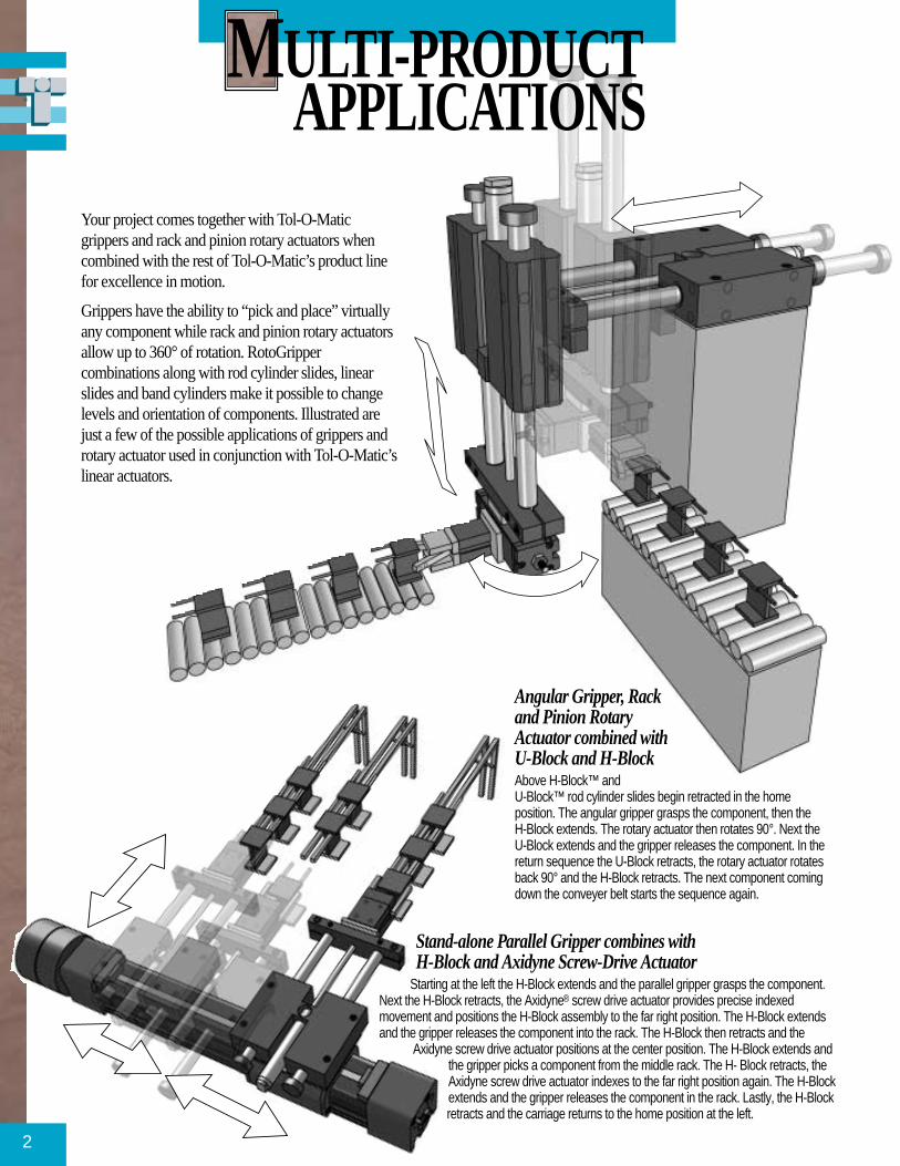
Stand-alone Parallel Gripper combines with H-Block and Axidyne Screw-Drive Actuator
Starting at the left the H-Block extends and the parallel gripper grasps the component.Next the H-Block retracts, the Axidyne® screw drive actuator provides precise indexedmovement and positions the H-Block assembly to the far right position. The H-Block extendsand the gripper releases the component into the rack. The H-Block then retracts and the
Axidyne screw drive actuator positions at the center position. The H-Block extends andthe gripper picks a component from the middle rack. The H- Block retracts, theAxidyne screw drive actuator indexes to the far right position again. The H-Blockextends and the gripper releases the component in the rack. Lastly, the H-Blockretracts and the carriage returns to the home position at the left.
2
Angular Gripper, Rackand Pinion RotaryActuator combined withU-Block and H-BlockAbove H-Block™ and U-Block™ rod cylinder slides begin retracted in the homeposition. The angular gripper grasps the component, then the H-Block extends. The rotary actuator then rotates 90°. Next theU-Block extends and the gripper releases the component. In thereturn sequence the U-Block retracts, the rotary actuator rotatesback 90° and the H-Block retracts. The next component comingdown the conveyer belt starts the sequence again.
MULTI-PRODUCTAPPLICATIONS
Your project comes together with Tol-O-Maticgrippers and rack and pinion rotary actuators whencombined with the rest of Tol-O-Matic’s product linefor excellence in motion.
Grippers have the ability to “pick and place” virtuallyany component while rack and pinion rotary actuatorsallow up to 360° of rotation. RotoGrippercombinations along with rod cylinder slides, linearslides and band cylinders make it possible to changelevels and orientation of components. Illustrated arejust a few of the possible applications of grippers androtary actuator used in conjunction with Tol-O-Matic’slinear actuators.

Drive-In-Front RotoGripper combines with H-Block and BC2 Band CylinderThis application utilizes a Drive-In-Front RotoGripper unit. A parallel grippergrasps the part and the H-Block retracts. The gripper (attached to the rotaryactuator via a coupling kit) and the part are rotated 180° by the rotaryactuator. Tol-O-Matic’s BC2 Band Cylinder® actuates the H-Block assemblyto the right. The H-Block then extends and the gripper releases the part. TheH-Block retracts, and the gripper rotates, with the BC2 Band Cylinderreturning to the home position.
3
Drive-From-Behind RotoGripper Combinationcombines with Parallel Side Mount Bracket toH-BlockThis sequence starts (at right) when the H-Block extends. TheDrive-From-Behind RotoGripper is mounted to the toolingplate of the H-Block with a parallel side mount bracket. At theend of the stroke the parallel gripper grasps the component.The H-Block retracts and the Tol-O-Matic linear slide movesthe H-Block to the position at the left. The gripper (with thecomponent in its jaws) rotates 180°. The H-Block extends andthe gripper releases the component. The H-Block retracts andthe linear slide returns to the home position at right inpreparation for another sequence.

4
GRIPPERS
ANGULAR GRIPPERS
PARALLEL GRIPPER
NICKLE-PLATED FINGERSTYLE JAW (JS1)
• High-performance internalcomponents include an oil-impreg-nated bronze bearing which provides alubricated, low-friction guide surfacefor the piston shaft while stabilizingthe piston. Efficient piston designincorporates a shock-absorbingbumper on the piston, effective on theextension stroke. Groove on the pistonaccommodates a magnet for signallingeither dc Hall Effect or reed switches.
• Pretapped mounting holeson thehousing sides and end allow formultiple mounting options and may becombined with Tol-O-Matic rack andpinion rotary actuators and other Tol-O-Matic rod cylinder slides utilizingadapter plates. Dowel pin holes arealso provided for alignment checks.
Tol-O-Matic’s line of hardworkinggrippers are price competitive units,
available in both angular and parallelstyles and come in a range of six boresizes (3/8", 5/8", 1", 1-1/2", 2" and 3")for a multitude of light- or heavy-duty“pick-and-place” applications.
All Tol-O-Matic grippers are designedwith efficient, durable features and areprelubricated, making them long-lasting and dependable cycle after cycle.Double-acting for either internal or ex-ternal gripping applications, these grip-pers are totally field repairable as well.
DOUBLE-ACTINGJAWS FOR INTERNAL
OR EXTERNALGRIPPING FORCE
NICKLE-PLATEDFLUSH STYLE JAW (JS2)
HARDCOATANODIZED BODY
• Hardcoat anodized extruded bodyof light-weight 6063-T6 aluminum,features a smooth finished bore forlong seal life with low breakaway.
• Gripper jaw design incorporates ahardened steel actuator pin formaximum cam bearing surface andprecision-machined cam slot in jawkeeps backlash at a minimum. Sideblocks eliminate side play of jaws,are adjustable to compensate forwear and can be easily removed forquick jaw replacement if necessary.Both jaw styles are nickle-plated forrust-resistence. For reduced jawfriction and longer life, the 1-1/2", 2"and 3" bore parallel grippers featureball bearings riding on hardenedsteel rails in the jaw mechanism.
SIDE BLOCK ADJUSTMENTSTO COMPENSATE FOR WEAR
OR QUICK JAW REMOVAL
PRETAPPED HOLESIN JAW FOR
CUSTOMIZEDFINGER TOOLING
ATTACHMENT
Pretapped mounting holes onhousing side and end are standardon both angular and parallel grippersfor multiple mounting options.
Hardened steel actuator pin onangular and parallel styles allowmaximum bearing surface.

GRIPPER SELECTION
5
Grippers are used to move amultitude of various shaped
objects in different sizes and weights.As a result, many factors need to beconsidered when choosing the rightgripper for an application.
Movement, speeds, rotational speeds,center of gravity and inertias of thegripper as well as the part it will bemoving, all play a role in the selectionprocess. When choosing a gripper, thefollowing guidelines should beconsidered.
THE CENTER OF GRAVITY
Locate the center of gravity of the parton or as close to the center line of thegripper’s bore axis and between thegrip point of the jaws, as close to thegripper body as possible.
DETERMINE GRIPPERJAW AND FINGER SHAPE
Gripper jaws and finger tooling shouldconform to the shape of the part asclosely as possible, particularly if thecenter of gravity is outside the grip pointof the jaws.
DETERMINE THEGRIPPER JAW/FINGERCOEFFICIENT OFFRICTION
Jaw/finger attachments should be of amaterial that will provide a highcoefficient of friction when in contactwith the part it will be moving.
For example steel finger tooling pickingup a steel part has a low coefficient of
friction (0.3). In contrast, rubbermaterial in contact with steel has acoefficient of 1.0.
SAFETY FACTORS
Applying a safety factor will assure thegrip force is adequate for the conditionsof the application. Refer to the chartbelow for general guidelines indetermining safety factor values. Theseshould be used only as guidelines. Forcritical applications, please consult thefactory for additional technicalassistance regarding safety factors.
CG
C L
1.
1. 2. 3. 4. 5. 6.
2.
3.
4.
Review the 6 categories listed and assign a safety value for each (1, 2 or 3) if applicable to your application.Then take the sum of all values assigned, times the load weight to determine grip force required. Consult thegrip force calculations on page 6 and 13, or grip force performance charts on pages 7, 8 and 14, forappropriate gripper model.
GENERAL SAFETY FACTOR GUIDELINES
Safety Center of Gravity Conformation of Coefficient of Friction Linear Movement of Rotation of Part Deceleration ofValue of Load Jaw Profile to Part Between Jaw/Finger and Part Gripper (jaw position) 180° (speed) of Gripper Travel
1 Center of axis, grip Totally conforming
HIGH Jaws inline SLOW Shock absorber ordistance 1" or less Rubber on Steel = 1 with travel 5 seconds or more cushion
2 Center of axis, gripSemi-conforming
MEDIUM — MEDIUMBumperdistance more than 1" Plastic on Steel 2-1/2 to 5 seconds
3 Center of gravityNon-conforming
LOWJaws 90° of inline
FASTHard stopoutside of center axis Steel on Steel = .3 2-1/2 seconds or less

Tol-O-Matic angular grippersare available in two different
jaw styles. Finger jaw style (JS1)is available in three bore sizes of3/8", 5/8", 1" and 1-1/2". Flushjaw style (JS2) is available in allsix bore sizes of 3/8", 5/8", 1" , 1-1/2", 2" and 3".
Under normal operatingconditions, these angular grippershave a life expectancy of 10million cycles.
Jaw opening characteristics of each jawstyle provides 20° of travel.
6
5°15°
20°
Jaw opening grip force: Jaw closing grip force:
Where:
GF= Grip force (lbs.)
P = Applied system pressure (PSI)
L = Distance from jaw pivot to point of applied force (In)
Jo = Jaw opening multiplier constant (see chart)
Jc = Jaw closing multiplier constant (see chart)
FINGER JAWSTYLE (JS1)
LGF GF
L
FLUSH JAWSTYLE (JS2)
CALCULATING GRIP FORCE OF ANGULAR GRIPPERS
GFP
LJO=
−( ) ×10
GFP
LJC=
−( ) ×10
ANGULAR GRIPPER OPTIONS:• dc Reed Switches (Form A or Form C)• ac Triac Reed Switches • dc Hall-effect sinking or sourcing Switches • VITON® seals
MULTIPLIER CONSTANTSGPA038 GPA063 GPA100 GPA150 GPA200 GPA300
Jo .015 .070 .278 .663 1.473 4.103
Jc .013 .057 .239 .589 1.328 3.847
* 180°F is the maximum operating temperature when using magnets. Therefore magnets should not be used with the VITON seal option.
OVERALL MODEL SPECIFICATIONS GPA038 GPA063 GPA100 GPA150 GPA200 GPA300
Bore Size (in.) .375 .625 1.00 1.50 2.00 3.00
Max. Air Pressure (PSI) 100 100 100 100 100 100
Grip Force at 100 PSI (open) (lbs.) 1.8 @ L=.751" 6.0 @ L=1.0" 25 @ L=1.60" 59 @ L=1.0" 132 @ L=1.0" 368 @ L=1.0"
Grip Force @ 100 PSI (closed) (lbs.) 1.6 @ L=.751" 5.1 @ L=1.0" 21 @ L=1.60" 53 @ L=1.0" 119 @ L=1.0" 346 @ L=1.0"
Weight (lbs.) with JS1 Finger Jaw .09 .22 .61 NA NA
Weight (lbs.) with JS2 Flush Jaw .11 .26 .62 1.52 3.5 8.1
Operating Temp. (°F) (Buna-N seals) 0°-180° 0°-180° 0°-180° 0°-180° 0°-180° 0°-180°
Operating Temp.* (°F) (Viton® seals) 0°-240° 0°-240° 0°-240° 0°-240° 0°-240° 0°-240°
Max. Breakaway (PSI) 10 10 10 10 10 10
Stroke 20° 20° 20° 20° 20° 20°
ANGULAR GRIPPER SPECIFICATIONS
JAWS RETRACTED JAWS EXTENDED
AIRIN
AIRIN
ANGULAR GRIPPER ACTUATION

7
ANGULAR GRIPPER PERFORMANCE DATA
0.0
0.5
1.0
1.5
2.0
0 10 20 30 40 50 60 70 80 90 100
GRIP
FORC
E (L
BS.)
PRESSURE (PSI)
JAWS OPENING
JAWS CLOSING
GPA038
0
1
2
3
4
5
6
7
0 10 20 30 40 50 60 70 80 90 100GR
IP FO
RCE
(LBS
.)PRESSURE (PSI)
JAWS OPENING
JAWS CLOSING
GPA063
0
5
10
15
20
25
0 10 20 30 40 50 60 70 80 90 100
GRIP
FORC
E (L
BS.)
PRESSURE (PSI)
JAWS OPENING
JAWS CLOSING
GPA100
0
10
20
30
40
50
60
0 10 20 30 40 50 60 70 80 90 100
GRIP
FORC
E (L
BS.)
PRESSURE (PSI)
JAWS OPENING
JAWS CLOSING
0
20
40
60
80
100
120
0 10 20 30 40 50 60 70 80 90 100
GRIP
FORC
E (L
BS.)
PRESSURE (PSI)
JAWS OPENING
JAWS CLOSING
GPA200
0
50
100
150
200
250
300
350
400
0 10 20 30 40 50 60 70 80 90 100
GRIP
FORC
E (L
BS.)
PRESSURE (PSI)
JAWS OPENING
JAWS CLOSING
GPA300
GPA150
GRIP FORCE vs PRESSURE

GFO 100PSI GFO80PSI GFO60PSIGFC100PSI GFC80PSI GFC60PSI
8
0.0
0.5
1.0
1.5
2.0
2.5
3.0
0.5 1.0 1.5 2.0
GRIP
FORC
E (L
BS.)
DISTANCE FROM PIVOT (IN.)
GPA038
0
2
4
6
8
10
12
0.5 1.0 1.5 2.0 2.5 3.0GR
IP FO
RCE
(LBS
.)
DISTANCE FROM PIVOT (IN.)
GPA063
0
5
10
15
20
25
1.0 2.0 3.0 4.0 5.0
GRIP
FORC
E (L
BS.)
DISTANCE FROM PIVOT (IN.)
GPA100
0
10
20
30
40
50
60
1.0 2.0 3.0 4.0 5.0 6.0
GRIP
FORC
E (L
BS.)
DISTANCE FROM PIVOT (IN.)
GPA150
2.0 4.0 6.0 8.0
GRIP
FORC
E (L
BS.)
DISTANCE FROM PIVOT (IN.)0
10
20
30
40
50
60
70GPA200
G S
2.0 4.0 6.0 8.0
GRIP
FORC
E (L
BS.)
DISTANCE FROM PIVOT (IN.)
0
50
100
150
200
GPA300
ANGULAR GRIPPER PERFORMANCE DATA
GRIP FORCE vs LENGTH TO PIVOT
ODEL GPA063

9
ANGULAR GRIPPERSDIMENSIONS
CLOSE15° OPEN
OPEN
TRAVEL ZZ
YY
XX
WW
J20°
VV
DDD TAPPED HOLE (4)CENTEREDON Y2 NEAR 2 FAR
CCCAAA
BBB
Y
BBAA
H
#4-40 x .16TAPPEDHOLE (2)
.375.695
.500
.800
.375
.425
.856
.250
.320.542
#4-40 x .16TAPPEDHOLE (2)(SAME ONOPPOSITESIDE)
.222
.550
.125
TAPPED HOLE ONLY DOWEL HOLE ONLY
10-32 PORT (2)
TRAVELEACH JAW
OPENCLOSE
ANGULAR STYLE ONE
CLOSE
OPEN
ANGULAR STYLE TWO
#4-40 x .12 TAPPED HOLE(4) 2 EACH JAW
.500
#4-40 TAPPED HOLE THRU (4)2 EACH FINGER
.1255°
15°
20°
5°
15° 20° TRAVELEACH JAW
.250
.375
.500 .250 .250±.0010.5000±.0008
.751
1.0521.228
.750
.125
.250
.245 .540
.125.250
.372
.250
.8561.228.532
1.0521.313
.370
.373
.375
.188
.100
.250
.535.684
#4-40 x .16TAPPED HOLE (2)
.061/.062 x .13DOWEL HOLE (2)
.320
.532
FINGER STYLE JAW (JS1)
FLUSH STYLE JAW (JS2)
MODEL GPA038

FLUSH STYLE JAW (JS2)
ANGULAR GRIPPERSDIMENSIONS
10
15° OPENOPEN
TRAVEL ZZ
YY
XX
WW
J20°
VV
DDD TAPPED HOLE (4)CENTEREDON Y2 NEAR 2 FAR
CCCAAA
BBB
Y
BBAA
ZG
H
.1240 ± .0005 x .13DOWEL HOLE (2)
TAPPED HOLE ONLY DOWEL HOLE ONLY.950
.685 .343
.250±.0010.5000±.0008
.3425±.0010.6850±.0008
1.200.950
.390
1.516 .600
.885
20°TRAVEL
EACH JAW
#6-32 x .25TAPPEDHOLE (4)
.685
.550
.343
#6-32 x .25 TAPPED HOLE (3)2 AS SHOWN 1 PER OPPOSITE VIEW
.935
.468
.343.203
.550.200 .585
.374
.376
.188
#6-32 TAPPED HOLETHRU (4)2 EACH FINGER
.375
.2131.000
.2195°
15°
1.174
1.797
OPENCLOSE
10-32 PORT (2)
#6-32 x .25TAPPED HOLE (2)
.475
FINGER STYLE JAW (JS1)
.437 .594
.188.374.376
1.909
15°
5°
20° TRAVELEACH JAW
OPEN
CLOSE
1.1741.797
.188
.188
.375
.751
.936
#6-32 TAPPED HOLETHRU (6)3 EACH FINGER
MODEL GPA063

11
BA
CD
E DOWEL HOLE(2) x F DEEP
GH
JK
L TAPPEDHOLE (2)
TOP VIEW GPA100
BA
CD
E DOWEL HOLE(2) x F DEEP
GH
JK
L TAPPEDHOLE (4)
TOP VIEW GPA150
NP
M TAPPEDHOLE (2)
RS TAPPED
HOLETHRU (4)2 EACHFINGER
U
T
XW
V
Y
BB
AA
CC
Z
EE
DD TAPPEDHOLE (4)
FF
GG
20°TRAVEL
EACH JAW
5°
15°
OPENCLOSE
JJHH
LLKK TAPPEDPORT (2)
MM
NN
PPRR
SS TT
UU
VV
15°
5°
20° TRAVELEACH JAW
OPEN
CLOSE
WW
XXYY
ZZ
AAA
BBB TAPPEDHOLE (6)
3 EACH JAW
FINGER STYLE JAW (JS1)
FLUSH STYLE JAW (JS2)
CLOSE15° OPEN
OPEN
TRAVEL ZZ
YY
XX
WW
J20°
VV
DDD TAPPED HOLE (4)CENTEREDON Y2 NEAR 2 FAR
CCCAAA
BBB
Y
BBAA
ZG
H
MODEL GPA100 & 150
GPA 100 150A 1.1150 1.6000
± .0008 ± .0008
B .5575 .800± .0010 ± .001
C .2875 .500± .0010 ± .001
D .5750 1.000± .0008 ± .0008
E .124 / .1245 /.1255 .1235
F .20 .25
G .500 .750
H 1.000 1.500
J 1.000 1.500
K .500 .750
L #8-32 UNC 10-32-2B x .22 x .38
M #8-32 UNC NAx .22
N 1.000 NA
P .500 NA
MODEL R S T U V W X Y Z AA BB CC DD EE FF GG HH JJ KKGPA100 .750 10-24 x .28 .312 .625 .250 .499/.501 .6875 1.375 1.000 1.952 1.600 .330 #8-32 x .22 1.416 .875 .313 2.377 1.500 10-32
GPA150 NA 1/4-28 UNF-2B .375 1.000 .375 .750 .990 1.980 1.500 2.637 2.000 .437 10-32 X .38 1.500 1.000 .512 3.075 2.012 10-32
LL MM NN.250 .750 .500
.615 1.001 .676
GPA 100 150PP .250 .375
RR .500 .750
SS .625 .672
TT .812 .859
UU 1.875 1.980
VV 2.539 3.215
WW .250 .375
XX .187 .311
YY .500 .625
ZZ .875 1.103
AAA 1.250 1.435
BBB 10-24 x .28 10-32 x .44
All dimension in inches
All dimension in inches

CLOSE15° OPEN
OPEN
TRAVEL ZZ
YY
XX
WW
J20°
VV
DDD TAPPED HOLE (4)CENTEREDON Y2 NEAR 2 FAR
CCCAAA
BBB
Y
BBAA
ZG
H
MODEL GPA200 & 300
ANGULAR GRIPPERSDIMENSIONS
12
CD
AB
FF/2
E/2E
K
LNP
M/2M
J/2J
V
WOPEN
CLOSE
BB TAPPED HOLE (6)3 EACH JAW
G DOWEL HOLE (2)x H DEEPU TAPPED HOLE (4)
U TAPPEDHOLE (4)
20° TRAVELEACH JAW
15°
5°
ST
RR/2 GG
PORT (2)
Y
Z
AA
J/2J
X
M/2
CCDD
FFEE/2
EE
FLUSH STYLE JAW (JS2)
MODEL A B C D E F G H J K L M N P R S T U V
GPA200 2.1000 1.050 1.1000 .550 1.960 1.960 .2485 .375 2.480 2.393 1.557 1.000 .785 1.068 1.960 4.097 3.378 1/4-28 .800±.0008 ±.001 ±.0008 ±.001 .2495 x .38
GPA300 3 .0000 1.500 1.813 ± .906 2.750 2.750 .2490 .375 3.500 3.550 2.086 1.040 1.118 1.558 2.323 5.876 4.758 5/16 1.500±.0008 ±.001 .0008 ± .001 .2500 x .5
W X Y Z AA BB CC DD EE FF GG
.865 .615 1.100 .862 .740 1/4-28 .375 .750 3.544 1.381 1/8-27x .38 NPT
.900 1.000 1.625 1.320 1.230 3/8-16 .500 .847 4.821 1.847 1/8-27x.66 NPT
All dimension in inches

13
PARALLEL GRIPPERSSPECIFICATIONS
Tol-O-Matic parallel style grippers are available in 3/8", 5/8", 1", 1-1/2",2" and 3" bore sizes. Larger bore sizes of 1-1/2", 2" and 3", utilize ball
bearings on harden steel rails in the jaw mechanism for reduced jaw frictionand longer life.
Under normal operating conditions, these parallel grippers have a life expectancy of 10 million cycles.
PARALLEL GRIPPER OPTIONS:
• dc Reed Switches (Form A or Form C)• ac Triac Reed Switches• dc Hall-effect Sourcing or Sinking Switches.• VITON® Seals
MULTIPLIER CONSTANTSGPP038 GPP063 GPP100 GPP150 GPP200 GPP300
Jo .034 .090 .236 .550 1.052 2.319
Jc .038 .107 .274 .618 1.173 2.650
Jaw opening grip force: Jaw closing grip force:
Where:
GF= Grip force (lbs.)
P = Applied system pressure (PSI)
Jo = Jaw opening multiplier constant (see chart)
Jc = Jaw closing multiplier constant (see chart)
NOTE: For modelsGPP038 and GPP063,reduce grip force by 20%for each additional 1/2"from jaw face. For modelsGPP100, GPP150,GPP200 and GPP300reduce grip force by 20%for each additional 1" fromjaw face.
CALCULATING GRIP FORCE OF PARALLEL GRIPPERS
GF P Jo= −( ) ×10 GF P Jc= −( ) ×10
OVERALL MODEL SPECIFICATIONS GPP038 GPP063 GPP100 GPP150 GPP200 GPP300
Bore Size (in.) .375 .625 1.00 1.50 2.00 3.00
Max. Air Pressure (PSI)* 100 100 100 100 100 100
Grip Force at 100 PSI (open) (lbs.) 3.1 8.1 21.2 49.5 95.7 208.7
Grip Force at 100 PSI (closed) (lbs.) 3.4 9.63 24.7 55.6 105.6 238.5
Weight (lbs.) .09 .24 .63 2.54 6.5 13.3
Operating Temp. (°F) (Buna-N Seals) 0°-180° 0°-180° 0°-180° 0°-180° 0°-180° 0°-180°
Operating Temp. (°F) (VITON Seals) 0°-240° 0°-240° 0°-240° 0°-240° 0°-240° 0°-240°
Max. Breakaway (PSI) 10 10 10 10 10 10
Stroke per Jaw (in.) .125 .125 .200 .250 .35 .500
Total Stroke (in.) .250 .250 .400 .500 .70 1.00* 180°F is the maximum operating temperature when using magnets. Therefore magnets should not be used with the VITON seal option.
1/2" 1"1/2"
1"
JAWS RETRACTEDJAWS EXTENDED
AIRIN
AIRIN
PARALLEL GRIPPERACTUATION

14
0.0
0.5
1.0
1.5
2.0
2.5
3.0
3.5
4.0
0 10 20 30 40 50 60 70 80 90 100
GRIP
FORC
E (L
BS.)
PRESSURE (PSI)
JAWS OPENING
JAWS CLOSING
GPP038
0
2
4
6
8
10
12
0 10 20 30 40 50 60 70 80 90 100GR
IP FO
RCE
(LBS
.)PRESSURE (PSI)
JAWS OPENING
JAWS CLOSING
GPP063
0
5
10
15
20
25
30
0 10 20 30 40 50 60 70 80 90 100
GRIP
FORC
E (L
BS.)
PRESSURE (PSI)
JAWS OPENING
JAWS CLOSING
GPP100
0
10
20
30
40
50
60
0 10 20 30 40 50 60 70 80 90 100
GRIP
FORC
E (L
BS.)
PRESSURE (PSI)
JAWS OPENING
JAWS CLOSING
GPP150
0
20
40
60
80
100
120
0 10 20 30 40 50 60 70 80 90 100
GRIP
FORC
E (L
BS.)
PRESSURE (PSI)
JAWS OPENING
JAWS CLOSING
GPP200
0
50
100
150
200
250
0 10 20 30 40 50 60 70 80 90 100
GRIP
FORC
E (L
BS.)
PRESSURE (PSI)
JAWS OPENINGJAWS CLOSING
GPP300
PARALLEL GRIPPERSPERFORMANCE DATA
GRIP FORCE vs PRESSURE

15
TAPPED HOLE ONLY DOWEL HOLE ONLY.500.250
.375
.500 .250 .250±.0010.5000±.0008
#4-40 x.16TAPPED
.375.695
.500
.800
.375
.425
.125
.250
.245 .540
.750
.375
.8561.351 .125
.328
.330.374.376
.187
.251
.253
.063
.063
.250
.320.542
.320#4-40 x .16TAPPEDHOLE (2)(SAME ONOPPOSITESIDE)
.222
.550
.125
#6-32 x .24 TAPPED HOLECENTERED 1 AS SHOWN1 OPPOSITE
10-32 PORT (2)
1.046OPEN.840
CLOSE
#4-40 x .16TAPPED HOLE (2)
.061/.062 x .13DOWEL HOLE (2)
CLOSE15° OPEN
OPEN
TRAVEL ZZ
YY
XX
WW
J20°
VV
DDD TAPPED HOLE (4)CENTEREDON Y2 NEAR 2 FAR
CCCAAA
BBB
Y
BBAA
H
MODEL GPP038
PARALLEL GRIPPERS

16
.1240 ± .0005 x .13DOWEL HOLE (2)
TAPPED HOLE ONLY DOWEL HOLE ONLY.950
.685 .343
.250±.001.5000±.0008
.3425±.0010.6850±.0008
1.200.950
.390
1.959.600
1.537CLOSE1.787OPEN
6-32 x .25TAPPEDHOLE (4)
.685
.550
.343
6-32 x .25 TAPPED HOLE (3)2 AS SHOWN 1 PER OPPOSITE VIEW
.935
.468
.343.203
.550.200 .585
.250.562.563
.162.3756-32 x .19
TAPPED HOLE (4)CENTERED2 AS SHOWN2 OPPOSITE
10-32 PORT (2)
6-32 x .25TAPPED HOLE (2)
TRAVEL ZZ
YY
XX
WW
J20°
VV
DDD TAPPED HOLE (4)CENTEREDON Y2 NEAR 2 FAR
CCCAAA
BBB
Y
BBAA
H
MODEL GPP063
PARALLEL GRIPPERS

PARALLEL GRIPPERS
17
#8-32UNC-2B X .22 DP (2)
ø .1245/.1235 x .20 DEEP (2)
1.1150± .0008
.5575± .0010
1.000.500
TAPPEDHOLESONLYDOWEL
HOLESONLY
.5001.000
TAPPEDHOLESONLY
.5750± .0008
.2875± .0010DOWELHOLESONLY
1.000
.750
.500
#8-32 x .22 TAPPED HOLE (3)2 AS SHOWN 1 PER OPPOSITE VIEW
1.375
.6875
1.000
2.626.875
1.975CLOSE2.375OPEN
.500
.750
.375.749.750
.250.499.501
#8-32 x .23TAPPED HOLE (4)CENTERED2 AS SHOWN2 OPPOSITE
1.875
1.500
.313
10-32 TAPPEDPORT (2)
.75
#8-32 x .22 DP
1.375 .250
OPEN
TRAVEL ZZ
YYWW
J20°
DDD TAPPED HOLE (4)CENTEREDON Y2 NEAR 2 FAR
CCCAAA
BBB
Y
BBAA
H
MODEL GPP100

MODEL A B C D E F G H J K L M N P R S T U V
GPP150 1.6000 .800 1.0000 .500 1.500 1.500 .1250 .25 1.980 2.012 1.390 .750 1.170 .500 .295 1.500 10-32 1.000 .512±.0008 ±.001 ±.0008 ±.001 .1240 x .38
GPP200 2.1000 1.050 1.1000 .550 1.960 1.960 .2490 .375 2.480 2.393 1.523 .693 1.048 .375 .375 1.960 1/4-28 .800 .865±.0008 ±.001 ±.0008 ±.001 .2500 x .38
GPP300 3.0 00 1.500 1.8130 .906 2.750 2.750 .2490 .375 3.500 3.550 1.960 1.040 1.592 .544 .689 2.750 5/16-18 1.500 .900±.0008 ±.001 ±.0008 ± .001 .2500 x .50
18
CD
AB
FF/2
E/2E
SS/2
U
V
W/2W CLOSEX OPEN
K
LP
R
N
M/2M
EE/2EE
M/2M
FF
GG
HH
X/2
J/2J
KK
DD TAPPED HOLEGPP150: 4 EACH JAWGPP200: 5 EACH JAWGPP300: 5 EACH JAW
T TAPPEDHOLE (4)
G DOWEL HOLE (2)x H DEEPT TAPPED HOLE (4)
JJPORT (2)
BB
Z
AA
CC
J/2J
Y
TRAVEL ZZ
YY
XX
WW
VV
DDD TAPPED HOLE (4)CENTEREDON Y2 NEAR 2 FAR
CCCAAA
BBB
Y
ZG
HMODEL GPP150, 200 & 300
PARALLEL GRIPPERS
W X Y Z AA BB CC DD EE FF GG HH JJ KK
4.245 4.745 .615 1.011 .676 3.467 .615 10-32 4.125 .500 .625 1.652 10-32 NAx .50
5.964 6.664 .615 1.100 .834 3.968 .893 1/4-28 5.916 .547 .700 2.321 1/8-27 .700x .38
8.996 9.996 1.000 1.625 1.320 5.662 1.230 3/8-16 8.874 .943 1.000 3.559 1/8-27 1.000x .62

19
In comparison with other rotaryactuators, Tol-O-Matic’s rack and
pinion rotary actuator has one of thehighest torque per weight ratios andfeatures a light-weight, compactpackage. Available in 3/4", 1" and 1-1/4" bore sizes with rotation optionsof 0° to 180° and 0° to 360°, theseactuators fill a wide variety ofapplication requirements.
Its low-profile, single rack designgives it a big advantage over bulkierdouble rack models and its anodized
ADJUSTABLE STOPS WITHNYLON BUMPERS FOR LOW
INERTIA APPLICATIONS
PRETAPPED MOUNTING HOLESON BACKSIDE OF HOUSING
BALL BEARING REDUCES FRICTIONAND PROVIDES SUPPORT AGAINST
SIDE LOADING OF PINION AND SHAFT EXTRUDED, LIGHT-WEIGHT,ANODIZED ALUMINUM HOUSINGS
SINGLE RACK AND PINION DESIGNFOR COMPACT, LOW-PROFILE
extruded aluminum housing makes itdurable and light-weight.
Sintered bronze guide block eliminatesbacklash by preloading the rack into thepinion throughout the stroke. Ballbearings reduce friction for maximumefficiency, rigidity and support to pinionshaft and allow the actuator shaft towithstand substantial side loads.
Adjustable stops with nylon bumpersoffer stroke adjustment and shockabsorption on low-inertia applications.Shock absorbers can be mounted inplace of the adjustable stops todecelerate and limit travel in high
inertia applications. Optionaladjustable cushions can be utilized forend of travel deceleration. Additionaloptions include Hall-effect sinking orsourcing sensors for signalingposition.
All Tol-O-Matic rack and pinionrotary actuators are prelubricated,easily field repairable and are rated for10,000,000 cycles under normaloperating conditions.
Adjustable sinteredbronze guide blockeliminates backlashthroughout stroke.
Acetal piston design floatsindependent of rack.
RACK AND PINIONROTARY ACTUATORS

20
RACK AND PINIONROTARY ACTUATORSSELECTION
MOMENTS OF INERTIA EXAMPLES
k
W
k
ab
c
W1W2
ab
W1
W2
POINT LOAD
THIN DISK MOUNTED ON CENTER THIN RECTANGULAR PLATE MOUNTED OFF CENTER
SLENDER ROD MOUNTEDOFF CENTER
To select a rack and pinion rotaryactuator, the following application
data is required:
• Torque required to rotate the load.
• Degree of rotation.
• Pressure available (PSI).
• Radial and/or thrust loads.
Refer to the performance charts onpage 21 to determine the followingselection specifications.
DETERMINE TORQUEOUTPUT AT AVAILABLEPRESSURE
Refer to the Torque vs Pressure chartand choose a rotary actuator based on itstorque output at the available operatingpressure that will rotate the load.
DETERMINE ACTUATORSBEARING LOADCAPACITY
Consult the Bearing Load Capacitychart. Bearing loads must not exceedthe values shown for radial and/orthrust loading.
CALCULATE KINETICENERGY IF APPLICABLE
Kinetic energy comes into play if theactuator will decelerate the load. Inthese applications, both torque output torotate the load and kinetic energyabsorption to stop the load must beconsidered to correctly size a rotaryactuator.
Once the KE value per stop has beencalculated, refer to the Rotary ActuatorKinetic Energy Rating chart anddetermine if standard adjustable stops
with bumpers are adequate or if optionalcushions or shock absorbers will berequired.
How to calculate kinetic energy isshown below.
KE J
angle traveledrotation time
where
KE Kinetic Energy per stop in lbs
J Rotational mass moment of
inertia in lbs
Peak Velocity rad
assu g twice average
velocity
W Weight of load lbs
g Gravitational cons t
in
m
m
=
= ×
= −=
− −=
== =
12
0 035
386 4
2
2
ω
ω
ω
. (deg.)
(sec.)
( . .)
( . sec. )
( . / sec.)
( min
)
( .)
tan
. .. / sec.
( .)
2
k Radius of gyration in=
KINETIC ENERGY CALCULATION
JWg
a Wg
bm = × + ×1
22
2
3 3
JWg
km = ×
2
2
JWg
km = × 2
JWg
a c Wg
b cm = × + + × +1
2 22
2 2412
412
1.
2.
3.

Rack and pinion rotary actuators are available in three bore sizesof 3/4", 1" and 1-1/4" with 0° to 180° or 0° to 360° rotations.
OPTIONS:
• dc Hall-effect Sinking or Sourcing Switches• Cushions• Shock Absorbers• VITON Seals
21
RACK AND PINIONROTARY ACTUATORSSPECIFICATIONS
*180° F is the maximum operating temperature when using magnets. Therefore magnets should not be used with the VITON seal option.
PERFORMANCE DATA
0
10
20
30
10080604020
1 1/4" Bore
1" Bore
3/4" Bore
PSI
IN./L
BS
TORQUE VS PRESSURE (actual)
KINETIC ENERGY RATINGSKinetic Energy Absorption (in.-lbs.)/Stop
THRUST LOAD
RADIAL LOAD
DISTANCE BETWEEN BEARINGS
BEARING LOAD CAPACITIES
ModelRadial Thrust Bearing Spread(lbs.) (lbs.) (in.)
RA075 105 26 .68RA100 235 59 .84RA125 360 90 1.06
ADJUSTABLE STOPSModel KE/StopRA075 .14RA100 .26RA125 .26
CUSHIONSModel KE/StopRA075 .50RA100 .92RA125 1.84
SHOCK ABSORBERSModel KE/Stop Max. Cycles/Hr.RA075 1.00 3896RA100 3.00 5195RA125 4.00 3911
OVERALL SPECIFICATIONS
SPECIFICATIONMODEL NUMBER
RA075 RA100 RA125Bore Diameter (in.) .750 1.000 1.250Degree of Rotation 180 / 360 180 / 360 180 / 360Base Weight (lbs.) w/180° rotation .60 .78 1.35 Base Weight (lbs.) w/360° rotation .71 1.02 1.81Shaft Style: Single Single SingleTheoretical Torque Specs .072 in. lb. / psi .196 in. lb. / psi .409 in. lb. / psiMaximum Operating Pressure: 150 PSI 150 PSI 150 PSIMaximum Breakaway Pressure: 10 PSI 7 PSI 5 PSIEffective cushion range: 30° 30° 30°Standard Rotations: 180°, 360° fully adjustable 180°, 360° fully adjustable 180°, 360° fully adjustableOperating Temperature:* 0°F to 180°F (Buna-N seals) 0°F to 180°F (Buna-N seals) 0°F to 180°F (Buna-N seals)
0°F to 240° F (Viton® seals) 0°F to 240° F (Viton® seals) 0°F to 240° F (Viton® seals)Keyway Timing: 12 O’clock position at midstroke 12 O’clock position at midstroke 12 O’clock position at midstrokeHousing Material: Aluminum Aluminum AluminumShaft Material: Steel Steel SteelRack Material: Steel Steel SteelMaximum Angular Backlash 1.5° 1.0° 1.0°Rotational Tolerance +10° / -00° +7° / -00° +5° / -00°Volume/Degree of Rotation .0012 in.3 .0055 in.3 .0071 in.3

22
STROKE ADJUSTER THREAD KK
END WITH BUMPER
SYM. CL
SYM. CL
SYM. CL
BB DOWEL HOLE (2)
CC TAPPED HOLE (4)
DAMPENINGSCREW IS ONCUSHION ENDONLY
JJ PORT (2)
A
BC
DG
F
HJ
K (Maximum)
M
N
P
R
ST
U
V
AAX
Z Y
DD
EE
FFGG
HH
CC TAPPED HOLE (4)OPPOSITE SIDE
.002 M
W AM. STD. WOODRUFF KEY NO.
THREAD FFF
END WITH BUMPERSYM. CLDIMENSIONAL DATA
RACK AND PINIONROTARY ACTUATORS
MODEL DIMENSIONS IN INCHESModel A B C D F G H J K* M N P R S T U V
RA075-1801.062 1.08 .219 .438 .22
.0625 2.750 3.625 4.91.688 .531 .687 .525 .047
.2500.09 .260RA075-360 .0635 3.771 4.646 5.93 .2495
RA100-1801.313 1.43 .328 .594 .22
.0938 3.375 4.563 6.24.875 .656 .943 .625 .063
.3750.09 .260RA100-360 .0948 4.946 6.134 7.81 ..3745
RA125-1801.562 1.43 .328 .594 .38
.1250 4.125 5.313 6.99.989 .781 1.219 .656 .094
.5000.25 .260RA125-360 .1260 6.219 7.406 9.08 .4995
MODEL DIMENSIONS IN INCHESModel W X Y Z AA BB CC DD EE FF GG HH JJ KK
RA075-180202.5 .141 1.344 1.063 2.094
.1250 8-32.187 .750 .156 1.250 2.500. 10-32 3/8-32RA075-360 .1240 X .22 X .31
RA100-180303 .156 1.625 1.313 2.438
.1250 10-24.250 1.000 .156 1.500 3.000. 1/8-27 1/2-20RA100-360 .1240 X .22 X .38
RA125-180405 .172 1.906 1.563 2.625
.1250 10-24.359 1.219 .172 1.750 3.188. 1/8-27 1/2-20RA125-360 .1240 X .22 X .38
*K is adjustable.Dimension ismaximum value

MODEL A B C D E* F G H K*RA075 10-32 3/8-32 .219 .438 1.61 1/4-20 .281 .750 1.25
RA100 1/8-27 1/2-20 .328 .594 3.24 1/4-20 .344 .813 1.25
RA125 1/8-27 1/2-20 .328 .594 3.24 1/4-20 .344 .813 1.25
CUSHIONSHOCK ABSORBER
23
SHOCK ABSORBERSFor high inertia or cyclic applications, optional shock absorbers can be used toincrease the rotary actuators life and broaden the application range. Shocksutilize same thread sizes as standard adjustable stops, making them easilyinterchangeable and field retrofitable.
CUSHIONSFor low inertia applications, cushions may be added to deceleratethe load at the end-of-stroke. Adjustable cushions are available onall sizes of rack and pinion rotary actuators and feature a floatingcushion seal for positive load deceleration and fast exiting of thecushion on the return stroke.
THREAD FFF
END WITH BUMPERSYM. CLDIMENSIONAL DATA
T O P V I E WPORT
LEFT END RIGHT END
When ordering cushions or shock absorbersfor Rack and Pinion Rotary Actuators, specifyleft or right end. Refer to the illustration shownabove as viewed from the port side.
RACK AND PINIONROTARY ACTUATORSOPTIONS
*E & K areadjustable.Dimension ismaximum value
SHOCK/STROKEADJUSTERTHREAD B
C
DE
(Maximum)
A PORT (1)
A PORT (1) STROKEADJUSTERTHREAD F
(Maximum)
GH
K

DRIVE-FROM-BEHIND
DRIVE-IN-FRONT
24
Tol-O-Matic offers two types ofRotoGripper combinations:
Preassembled, prepackaged Drive-From-Behind combinations andstandard component Drive-In-Frontstyles which utilize coupling kits.
THE TOL-O-MATIC DRIVE-FROM-BEHINDROTOGRIPPER
Tol-O-Matic’s uniquely designedDrive-From-Behind RotoGripper has afixed gripper housing allowing air linesand sensors to remain completelystationary for a totally safe rotation ofthe lower gripper jaw assembly.
Available in 3 rotary actuator models(3/4", 1", or 1-1/4" bores), with a choiceof either angular or parallel grippers(5/8", or 1" bores), these preassembledcombinations are light-weight, compactand carry a low-profile.
Standard adjustable stops on the rackand pinion rotary actuator provideunlimited rotational settings forgripper jaw travel.
DRIVE-IN-FRONTCOMBINATIONS
Drive-In-Front RotoGrippers are anoption to Tol-O-Matic’s Drive-From-
Behind combinations. A simplecoupler kit easily combines Tol-O-Matic’s standard rack and pinionrotary actuators and grippers for abroader range of size selections.
Three sizes of rotary actuator models(3/4", 1" or 1-1/4" bores) can becombined with the appropriate sizeangular or parallel gripper (3/8", 5/8",1" or 1-1/2" bore) for 12 differentcombinations.
Both Drive-From-Behind and Drive-In-Front RotoGripper combinationscan be combined with Tol-O-Matic’srod cylinder slides using adapter platesfor a variety of multi-axis “pick-and-place” applications.
COUPLER KITCOMBINES STANDARD
COMPONENTS
FIXED GRIPPER HOUSINGFOR STATIONARY AIRLINES AND SENSORS
GRIPPER JAWS FREETO ROTATE WITHOUTANY RESTRICTIONS
ADJUSTABLE STOPSWITH POLYURETHANE
BUMPERS LIMITROTATIONAL TRAVEL
ROTOGRIPPERCOMBINATIONS

25
To select the proper RotoGrippercombination, each component of
the RotoGripper (the rotary actuator aswell as the gripper) must be sizedindividually according to theapplication requirements.
GRIPPER SELECTION
When choosing a gripper, refer to theselection information beginning on page5 of the gripper section in this catalog.
Select the appropriate angular orparallel gripper size and jaw styleaccording to the load requirements ofthe application and consider the safetyfactor values as well.
ROTARY ACTUATORSELECTION
Refer to pages 20-21 of the rack andpinion rotary actuator section forselection specifications.
Select a rotary actuator bore sizeaccording to its torque requirements,bearing load capacities and considerany options if required.
IMPORTANT NOTE: Calculate therotational mass moment of inertia (Jm)if the rotary actuator will physicallystop the load.
ROTOGRIPPERCOMBINATIONSSELECTION
1.
2.
3.
Then, calculate the Kinetic Energy perstop and determine if standardadjustable stops with bumpers,cushions or shock absorbers will berequired.
SELECT THEROTOGRIPPERCOMBINATION
When selection of the gripper androtary actuator components arecomplete, select which RotoGrippercombination (a drive-from-behind or adrive-in-front ) is desirable for theapplication.
Drive-From-Behind Combinations
The table shown below lists thepossible Drive-From-Behindcombinations that are available. Referto pages 38 and 39 of the orderingsection for configurating theappropriate model.
ROTARY ACTUATOR GRIPPER
RA075GPA063
GPP063
RA100GPA063
GPP063
RA100GPA100
GPP100
RA125GPA100
GPP100
NOTE: Both angular jaw styles of finger (JS1)and flush (JS2) are available in RotoGrippercombinations.
Drive-In-Front Combinations
Drive-In-Front combinations combineTol-O-Matic standard rack and pinionrotary actuators and grippers togetherutilizing coupler kits.
The table below lists the possible rotaryactuator and gripper combinations forDrive-In-Front styles. Refer to page 30for coupling kit specifications, partnumbers and ordering procedures.
ROTARY ACTUATOR GRIPPER
RA075
GPA038
GPP038
GPA063
GPP063
RA100
GPA063
GPP063
GPA100
GPP100
RA125
GPA100
GPP100
GPA150
GPP150
NOTE: Both angular jaw styles of finger (JS1)and flush (JS2) are available in RotoGrippercombinations.

Tol-O-Matic drive-from-behind RotoGrippercombinations can utilize all three sizes of rack and
pinion rotary actuators (3/4", 1" and 1-1/4"), combinedwith either angular or parallel grippers in 5/8" or 1"bore sizes.
Preassembled, theses unique combinations allowthe gripper jaws to rotate freely while keepingair lines and sensing wires stationary and out
of the rotational path.
DRIVE-FROM-BEHIND OPTIONS:
Drive-From-Behind combinations utilize the same optionsthat are available on all Tol-O-Matic grippers and rack andpinion rotary actuators.
26
DRIVE-FROM-BEHINDSPECIFICATIONS
ROTARY ACTUATOR/ANGULAR GRIPPER COMBINATIONS
Base Weights (lbs.)Models Available Bore (in.)
JS1 Jaw JS2 JawRotation
RGRA075RO18GPA063 .750 1.00 1.04 180°
RGRA075RO36GPA063 .750 1.11 1.15 360°
RGRA100RO18GPA063 1.00 1.19 1.23 180°
RGRA100RO36GPA063 1.00 1.43 1.47 360°
RGRA100RO18GPA100 1.00 1.65 1.66 180°
RGRA100RO36GPA100 1.00 1.89 1.90 360°
RGRA125RO18GPA100 1.25 2.35 2.36 180°
RGRA125RO36GPA100 1.25 2.81 2.82 360°
ROTARY ACTUATOR/PARALLEL GRIPPER COMBINATIONS
Models Available Bore Base Weights (lbs.) Rotation
RGRA075RO18GPP063 .750 1.04 180°
RGRA075RO36GPP063 .750 1.15 360°
RGRA100RO18GPP063 1.00 1.23 180°
RGRA100RO36GPP063 1.00 1.47 360°
RGRA100RO18GPP100 1.00 1.68 180°
RGRA100RO36GPP100 1.00 1.92 360°
RGRA125RO18GPP100 1.25 2.37 180°
RGRA125RO36GPP100 1.25 2.83 360°

Z
X Y
DD TAPPED HOLE (4)OPPOSITE SIDE
VV TAPPED HOLE (4)CENTEREDON S2 NEAR 2 FAR
10-32 PORT (2)
KK TAPPED HOLE (4)
JJ DOWEL HOLE (2)
LCSYM.
LCSYM.
LCSYM.
LK
N
M
R P
T
SU
VW RADIUS
AABB
CC (Maximum)
EE
FF
GG
HH
CLOSE 15° OPENOPEN
TRAVEL
20°RR
PP
NN
MM
LL
J
UUSS
TT
YY
ZZ
STROKEADJUSTERTHREAD XX
END WITH BUMPER
WW PORT (2)
FE
G
AB
C
D
H
.002 M
THREAD FFF
END WITH BUMPERSYM. CLDIMENSIONAL DATA
DRIVE-FROM-BEHINDANGULAR GRIPPER WITH FINGER STYLE JAW
MODEL DIMENSIONS IN INCHESModel A B C D E F G H J K L M N P R S
RGRA075RO18GPA063 1.844 1.200 1.174 .234 .531 1.062 .265 .922 1.200 .203 .935 .200 .585 NA .688 .375RGRAO75RO36GPA063RGRA100RO18GPA063 2.125 1.200 1.174 .625 .656 1.313 .265 .922 1.200 .203 .935 .200 .5.85 NA .875 .375RGRA100RO36GPA063RGRA100RO18GPA100 2.125 1.375 1.500 .250 .656 1.313 .312 1.156 1.875 .250 1.375 .250 .750 .125 .875 .500RGRA100RO36GPA100
RGRA125RO18GPA100 2.250 1.375 1.500 .594 .781 1.563 .312 1.156 1.875 .250 1.375 .250 .750 .047 .989 .500RGRA125RO36GPA100
27
T U V W X Y Z AA BB
.094 .525 .935 .77 1.063 1.344 2.094 2.750 3.6253.771 4.646
NA .625 .935 .77 1.313 1.625 2.438 3.375 4.5634.946 6.134
.125 .625 1.375 1.14 1.313 1.625 2.438 3.375 4.5634.946 6.134
.094 .656 1.375 1.14 1.563 1.906 2.625 4.125 5.3136.219 7.406
YY ZZ
1.000 .219 .213 .187 .375 6-32 10-32 3/8-32 .188 .62
1.000 .219 .213 .187 .375 6-32 1/8-27 1/2-20 .188 1.00
1.600 .330 .312 .250 .625 10-24 1/8-27 1/2-20 .188 1.00
1.600 .330 .312 .250 .625 10-24 1/8-27 1/2-20 .188 .92
MODEL DIMENSIONS IN INCHESModel CC* DD EE FF GG HH JJ KK LL MM NN PP RR SS TT UU VV WW XX
RGRA075RO18GPA063 4.91 8-32 1.87 .750 1.250 2.500 .1250 8-32 .906 .281 .885RGRA075RO36GPA063 5.93 x .31 .1240x22 x .31
RGRA100RO18GPA063 6.24 10-24 .250 1.000 1.500 3.000 .1250 10-24 .906 .281 .885RGRA100RO36GPA063 7.81 x .38 .1240x22 x .38
RGRA100RO18GPA100 6.24 10-24 .250 1.000 1.500 3.000 .1250 10-24 1.046 .424 1.416RGRA100RO36GPA100 7.81 x .38 .1240x22 x .38
RGRA125RO18GPA100 6.99 10-24 .359 1.219 1.750 3.188 .1250 10-24 1.046 .424 1.416RGRA125RO36GPA100 9.08 x .38 .1240x22 x .38
*CC is adjustable.Dimension ismaximum value

MODEL DIMENSIONS IN INCHESModel EE FF GG HH JJ KK *LL MM NN PP RR SS TT UU VV WW XX YY ZZ
RGRA075RO18GPA063 .77 1.063 1.344 2.094 2.750 3.625 4.91 8-32 .396 .751 .375 .188 1.250 2.500 1.87 .750 8-32 .1250 3/8-32RGRA075RO18GPA063 3.771 4.646 5.93 x .31 x .31 .1240x.22
RGRA100RO18GPA063 .77 1.313 1.625 2.438 3.375 4.563 6.24 10-24 .396 .751 .375 .188 1.500 3.000 .250 1.000 10-24 .1250 1/2-20RGRA100RO36GPA063 4.946 6.134 7.81 x .38 x .38 .1240x.22
RGRA100RO18GPA100 1.14 1.313 1.625 2.438 3.375 4.563 6.24 10-24 1.250 .875 .500 .187 1.500 3.000 .250 1.000 10-24 .1250 1/2-20RGRA100RO36GPA100 4.946 6.134 7.81 x .38 x .38 .1240x.22
RGRA125RO18GPA100 1.14 1.563 1.906 2.625 4.125 5.313 6.99 10-24 1.250 .875 .500 .187 1.750 3.188 .359 1.219 10-24 .1250 1/2-20RGRA125RO36GPA100 6.219 7.406 9.08 x .38 x .38 .1240x.22
28
HH
FF GG
MM TAPPED HOLE (4)OPPOSITE SIDE
DD TAPPED HOLECENTERED ON AA(6) 3 EACH JAW
10-32 PORT (2)
XX TAPPED HOLE (4)
YY DOWEL HOLE (2)
LCSYM.
LCSYM.
LCSYM.
RP
T
S
V U
W
AABB
CCEE RADIUS
JJKK
LL (Maximum)
VVWW
TT
UU
K
Z
J
AAA
STROKEADJUSTERTHREAD ZZ
END WITH BUMPER
M PORT (2)
FE
G
AB
C
D
H
.002 M
15°
5°
20° TRAVELEACH JAW
OPEN
CLOSE
L
NNPPRR
SS
BBB
THREAD FFF
END WITH BUMPERSYM. CLDIMENSIONAL DATA
DRIVE-FROM-BEHINDANGULAR GRIPPER WITH FLUSH STYLE JAW
MODEL DIMENSIONS IN INCHESModel A B C D E F G H J K L M P R S T U V
RGRA075RO18GPA063 1.844 1.200 1.174 .234 .531 1.062 .265 .922 .594 .437 .885 10-32 .203 .935 .200 .585 NA .688RGRA075RO36GPA063RGRA100RO18GPA063 2.125 1.200 1.174 .625 .656 1.313 .265 .922 .594 .437 .885 1/8-27 .203 .935 .200 .5.85 NA .875RGRA100RO36GPA063RGRA100RO18GPA100 2.125 1.375 1.500 .250 .656 1.313 .312 1.156 .812 .625 1.416 1/8-27 .250 1.375 .250 .750 .125 .875RGRA100RO36GPA100
RGRA125RO18GPA100 2.250 1.375 1.500 .594 .781 1.563 .312 1.156 .812 .625 1.416 1/8-27 .250 1.375 .250 .750 .047 .989RGRA125RO36GPA100
W Z AA BB CC DD
.094 .187 .375 .525 .935 6-32
NA .187 .375 .625 .935 6-32
.125 .250 .500 .625 1.375 10-24
.094 .250 .500 .656 1.375 10-24
AAA BBB
.188 .62
.188 1.00
.188 1.00
.188 .92
*LL is adjustable.Dimension ismaximum value

29
GG
EE FF
LL TAPPED HOLE (4)OPPOSITE SIDE
DD TAPPED HOLE (4)CENTEREDON W & Y2 NEAR 2 FAR
10-32 PORT (2)
TT TAPPED HOLE (4)
SS DOWEL HOLE (2)
LCSYM.
LCSYM.
LCSYM.
PN
S
R
U
V
T
Z
W X
Y
AA
BB
EE RADIUS
HHJJ
KK (Maximum)
MMNN
PP
RR
CC
WW
STROKEADJUSTERTHREAD UU
END WITH BUMPER
VV PORT (1)
FE
G
AB
C
D
H
J
K CLOSEL OPEN
.002 M
XX
THREAD FFF
END WITH BUMPERSYM. CLDIMENSIONAL DATA
DRIVE-FROM-BEHINDPARALLEL GRIPPER
MODEL DIMENSIONS IN INCHESModel A B C D E F G H J K L N P R S T U V
RGRA075RO18GPP063 1.844 1.200 1.174 .234 .531 1.062 .265 1.084 1.200 1.54 1.79 .203 .935 .200 .585 NA .688 .625RGRA075RO36GPP063
RGRA100RO18GPP063 2.125 1.200 1.174 .625 .656 1.313 .265 1.084 1.200 1.54 1.79 .203 .935 .200 .5.85 NA .875 .625RGRA100RO36GPP063
RGRA100RO18GPP100 2.125 1.375 1.500 .250 .656 1.313 .312 1.406 1.875 1.98 2.38 .250 1.375 .250 .750 .125 .875 .719RGRA100RO36GPP100RGRA125RO18GPP100 2.250 1.375 1.500 .594 .781 1.563 .312 1.406 1.875 1.98 2.38 .250 1.375 .250 .750 .047 .989 .719RGRA125RO36GPP100
W X Y Z AA BB CC
.563 .162 .375 .094 .525 .935 .250
.563 .162 .375 NA .625 .935 .250
.750 .250 .500 .125 .625 1.375 .375
.750 .250 .500 .094 .656 1.375 .375
MODEL DIMENSIONS IN INCHESModel DD EE FF GG HH JJ *KK LL MM NN PP RR SS TT UU VV WW XX
RGRA075RO18GPP063 6-32 1.063 1.344 2.094 2.750 3.625 4.91 8-32 1.87 .750 1.250 2.500 .1250 8-323/8-32 10-32 .188 .62RGRA075RO36GPP063 x .19 3.771 4.646 5.93 x .31 .1240 x .22 x .31
RGRA100RO18GPP063 6-32 1.313 1.625 2.438 3.375 4.563 6.24 10-24 .250 1.000 1.500 3.000 .1250 10-24 1/2-20 1/8-27 .188 1.00RGRA100RO36GPP063 x .19 4.946 6.134 7.81 x .38 .1240 x .22 x .38
RGRA100RO18GPP100 8-32 1.313 1.625 2.438 3.375 4.563 6.24 10-24 .250 1.000 1.500 3.000 .1250 10-24 1/2-20 1/8-27 .188 1.00RGRA100RO36GPP100 x .23 4.946 6.134 7.81 x .38 .1240 x .22 x .38RGRA125RO18GPP100 8-32 1.563 1.906 2.625 4.125 5.313 6.99 10-24
.359 1.219 1.750 3.188 .1250 10-241/2-20 1/8-27 .188 .92RGRA125RO36GPP100 x .23 6.219 7.406 9.08 x .38 .1240 x .22 x .38
*KK is adjustable.Dimension ismaximum value

30
Coupler Kits are available to easilycombine Tol-O-Matic’s rack andpinion rotary actuators with parallel orangular grippers for Drive-In-FrontRotoGripper combinations..
Coupler Kits can be utilized two ways.Combined with a rotary actuator andappropriate gripper or attached to afixed external member allowing therotary actuator to rotate freely.
To order the appropriate coupler kit,first configure the rotary actuatormodel, then configure the grippermodel. Select the correspondingCoupler Kit from the chart shownbelow.
If selected combination is not listed,please consult factory.
OPTIONS:
Drive-In-Front combinations utilize thesame optional features available forgrippers and rack and pinion rotaryactuators.
THREAD FFF
END WITH BUMPERSYM.
G
CLDIMENSIONAL DATAANGULAR GRIPPERFINGER STYLE JAW
ANGULAR GRIPPERFLUSH STYLE JAW
A
PARALLEL GRIPPER
DA B A C
DRIVE-IN-FRONTCOMBINATIONS
*Coupler Kits come complete with fastners, customized mounting plate and key.
OVERALL DIMENSIONS (INCHES)Combination A B C D
RotaryRA & Coupler
Angular Gripper Angular Gripper Parallel GripperActuator Gripper
Finger Jaw Flush JawRA075 GPA/GPP038 1.764 1.803 1.313 1.351
RA075 GPA/GPP063 1.764 2.516 1.909 1.959
RA100 GPA/GPP063 2.270 2.516 1.909 1.959
RA100 GPA/GPP100 2.270 3.552 2.539 2.627
RA125 GPA/GPP100 2.791 3.552 2.539 2.627
RA125 GPA/GPP150 2.791 NA 3.215 3.463
OVERALL UNIT SPECIFICATIONSCoupler Couples Coupler KitKit* No. Rotary Actuator To Gripper Weight (lbs.)
6000-9751 RA075 GPA/GPP038 .20
6000-9744 RA075 GPA/GPP063 .30
6000-9742 RA100 GPA/GPP063 .30
6000-9740 RA100 GPA/GPP100 .30
6000-9743 RA125 GPA/GPP100 .50
6000-9741 RA125 GPA/GPP150 .50

Available for use on all Gripper and Rack &Pinion Rotary Actuator models, these switches
are activated by the cylinder’s internal pistonmagnet assembly. DC Reed, Hall-effect and ACTriac switches contain reverse polarity protection.(Only Hall-effect switches are available for RotaryActuators.)
DC Reed Switches are designed for signalling end-of-strokeposition to devices such as programmable controllers. Theycan be used to operate dc relays and solenoids if a protectioncircuit is used and if current and voltage limits are observed.
Hall-effect switches are available in either sinking type(NPN), or sourcing type (PNP). They are designed to signaldevices such as programmable controllers, dc loads, and TTLor CMOS circuits.
ACTriac ReedSwitches aredesigned for signalling end-of-stroke position to devices such as programmable controllers.They can be used to operate ac relays and solenoids if aprotection circuit is used and if current and voltage limits areobserved.
31
REED SWITCHESSee page 33 for mounting dimensions.
NOTE: Cable is UNSHIELDED. Reedswitches can be used to operate relaysand solenoids if a protection circuit isused and if current, wattage andvoltage limits are observed. (Call thefactory for more information.)
NOT AVAILABLE FOR ROTARYACTUATORS
REED SWITCH
LOAD
BROWN
BLUE
BLUE
BLUE(-)(-)
(+)(+)
REED SWITCHLOAD
BROWN
BLUE(-)(-)
(+)(+)
OR
REED SWITCH
COMMONNORMALLY CLOSED
NORMALLY OPEN
BROWNBLACKBLUE
DC REED SWITCH SPECIFICATIONS
SWITCHES
* Data available from manufacturer.
SCEPS AMROF–HCTIWSDEER CMROF–HCTIWSDEER
STCATNOC ,worht-elgnis,elop-elgniSnepoyllamron
/nepo-yllamron,worht-elbuod,elop-elgniSdesolc-yllamron
GNITARTCATNOCotton(Am005tnerrucmumixam,sttaW01.sverutarepmeTotrefeR()AV01deecxe
).strahcgnitareDegatloVdnatnerruC
otton(Am052tnerrucmumixam,sttaW3.sverutarepmeTotrefeR()AV3deecxe
).strahcgnitareDegatloVdnatnerruC
EGATLOVTUPNI mumixamcdV002 mumixamca/cdV021
ECNATSISER )mumixaM(laitinIΩ1.0 )mumixaM(laitinIΩ1.0
EMITESAELER mumixam.ceSm0.1 mumixam.ceSm0.1
EMITGNITAREPO )ecnuobgnidulcni(mumixam.ceSm6.0 )ecnuobgnidulcni(mumixam.ceSm7.0
.PMETGNITAREPO )C°07(F°851ot)C°04-(F°04- )C°07(F°851ot)C°04-(F°04-
ROTACIDNI .nimAm4nehwtilDELdeRstcatnochguorhtswolf enoN
YCNATCEPXEEFIL*selcyc000,000,002otpU
dnaelcycytud,tnerrucdaolnognidneped()snoitidnoclatnemnorivne
selcyc000,000,002otpUdnaelcycytud,tnerrucdaolnognidneped(
)snoitidnoclatnemnorivne
ELBAC tekcajCVPhtiwretem5tekcajCVPhtiwtcennocsiD-kciuQm5rom2
tekcajCVPhtiwretem5tekcajCVPhtiwtcennocsiD-kciuQm5rom2
PORDEGATLOV [email protected] AN
PERFORMANCE DATA
REED SWITCH, FORM A WIRING DIAGRAM
REED SWITCH, FORM C WIRING DIAGRAM
0
100
200
300
400
500
600
0 20 40 60 80 100 120 140 160
LOAD
CUR
RENT
(mA)
OPERATING TEMPERATURE (°F)
REED FORM C
REED FORM A
TEMPERATURE vs CURRENT
0
50
100
150
200
0 100 200 300 400 500
VOLT
AGE
A.C.
or D
.C. (
mA)
CURRENT D.C (mA)
REED FORM A
REED FORM C
VOLTAGE DERATING

32
SWITCHES
DC HALL-EFFECTSWITCHES
Refer to next page for mounting data.
NOTE: Cable is UNSHIELDED.
HALL-EFFECT SOURCING
SWITCHBLACK
LOAD
BROWN
BLUE(-)
(+)
(-)
(+)
HALL-EFFECT SINKING SWITCH
BROWN
BLACK
BLUE(-)
(+)
(-)
(+)
LOAD
DC HALL-EFFECT SWITCH SPECIFICATIONS
SNOITACIFICEPS GNICRUOSTCEFFE-LLAH GNIKNISTCEFFE-LLAH
EGATLOVTUPNI cdV52ot5 cdV52ot5
TUPTUO hctiwsrotsisnartrotcellocnepO hctiwsrotsisnartrotcellocnepO
GNITARTUPTUO cdAm002,cdV52 cdAm002,cdV52
TNIOPPIRTNO mumixamssuaG531 mumixamssuaG531
TNIOPPIRTFFO muminimssuaG02 muminimssuaG02
GNITAREPO.PMET )C°66(F°051ot)C°81-(F°0 )C°66(F°051ot)C°81-(F°0
GNITAREPODEEPS .ceSm5< .ceSm5<
ROTACIDNI sirosnesnehwtilDELdeRdetavitca
sirosnesnehwtilDELdeRdetavitca
ELBACtekcajCVPhtiwretem5
htiwtcennocsiD-kciuQm5rom2tekcajCVP
tekcajCVPhtiwretem5htiwtcennocsiD-kciuQm5rom2
tekcajCVP
PERFORMANCE DATA
HALL-EFFECT SOURCINGSWITCH WIRING DIAGRAM
HALL-EFFECT SINKINGSWITCH WIRING DIAGRAM
AC TRIAC REEDSWITCHES
See next page for mounting dimensions.
NOTE: Cable is UNSHIELDED. Reedswitches can be used to operate relaysand solenoids if a protection circuit isused and if current, wattage and voltagelimits are observed. (Call the factory formore information.)
NOT AVAILABLE FOR ROTARYACTUATORS
AC COM
LOAD
INPUT
TRIAC SWITCH
120Vac Max.
MOV
BROWNBLUE
AC TRIAC REED SWITCH SPECIFICATIONS
* Data available from manufacturer.
SNOITACIFICEPS HCTIWSCAIRT
STCATNOC ,worht-elgnis,elop-elgniSnepoyllamron
EGATLOVTUPNI mumixamcaV021
YCNEUQERF zH36-74
SUOUNITNOCTNERRUC
;)C°03(F°68tapmA1)C°06(F°041tapmA5.0
EGRUSKAEPTNERRUC pmA01
GNITAREPO.PMET
F°851ot)C°04-(F°04-)C°07(
ROTACIDNI enoN
EFIL*YCNATCEPXE
selcyc000,000,002otpUdaolnognidneped(
dnaelcycytud,tnerruc)snoitidnoclatnemnorivne
ELBACtekcajCVPhtiwretem5
tcennocsiD-kciuQm5rom2tekcajCVPhtiw
PERFORMANCEDATA
TRIAC REED SWITCH WIRING DIAGRAM
0
200
400
600
800
1000
0 20 40 60 80 100 120 140 160
LOAD
CUR
ENT
(mA)
OPERATING TEMPERATURE (°F)
TRIAC
TEMPERATURE vs CURRENT

33
QUICK-DISCONNECT COUPLERSQuick-disconnect couplers are available for all switches in 2m and 5m lengths.These couplers allow switches to be removed quickly and easily. Switch includesone male-end coupler (hard wired to switch) and one female-end coupler withadditional cable for in-line splice. Replacement switch with hard-wired male-endconnector is available as a service part (see page 40 of this catalog).
NOTE: Quick-disconnect coupler is positioned 6" from the sensor.
VV
THREAD FFF
END WITH BUMPERSYM.
Z
E
G
CLMOUNTING DATANOTE: The scored face of the switch indicates the sensing surface and must face toward the magnet.
HALL-EFFECT SENSOR
ONLY
CIRCUIT BOARD WRAPPED IN HEAT SHRINK
HALL-EFFECT SENSOR
ONLY
CIRCUIT BOARD WRAPPED IN HEAT SHRINK
A
B B
B C
A
A
GP_038 GP_063 GP_100, GP_150 GP_200, GP_300
SENSING SURFACE
SENSING SURFACE
SENSING SURFACE
RA075, RA100, RA125 RA075 RA100 RA125
SIDE VIEW END VIEW
BA
HALL-EFFECT SENSOR ONLY CIRCUIT BOARD WRAPPED IN HEAT SHRINK
SENSING SURFACE
Above dimensions in inches
MODEL BORE A B CGP_038 .375 .34 .50 –GP_063 .625 .22 .50 –GP_100 1.000 .38 .50 1.25GP_150 1.500 .38 .50 1.25GP_200 2.000 .35 .50 1.25GP_300 3.000 .47 .50 1.25
Above dimensions in millimeters
MODEL BORE A B CGP_038 10 8.61 12.70 –GP_063 16 5.64 12.70 –GP_100 25 9.60 12.70 31.75GP_150 40 9.60 12.70 31.75GP_200 50 8.89 12.70 31.75GP_300 80 11.81 12.70 31.75
Above dimensions in inches
MODEL BORE A BRA075 0.75 .34 .50RA100 1.00 .34 .50RA125 1.25 .32 .50
Above dimensions in millimeters
MODEL BORE A BRA075 20 8.51 12.70RA100 25 8.51 12.70RA125 32 8.18 12.70

34
GRIPPERS
H-Block/U-Block Tooling Plateto Angular/Parallel Gripper Side Mount
Primary Secondary Plate Kit Thickness WeightActuator Actuator Number (in.) (oz.)
HB/UB09 GPA/GPP038 6000-9753 .325 3.25
HB/UB09 GPA/GPP063 6000-9710 .650 6.5
HB/UB12 GPA/GPP038 6000-9755 .325 1.75
HB/UB12 GPA/GPP063 6000-9713 .325 1.75
HB/UB17 GPA/GPP063 6000-9715 .450 5.0
HB/UB17 GPA/GPP100 6000-9717 .450 5.0
HB/UB24 GPA/GPP100 6000-9719 .450 7.25
HB/UB24 GPA/GPP150 6000-9720 .450 7.25
ADAPTER PLATESTol-O-Matic adapter plates are designed for center-to-center alignment to
help simplify installation. Each adapter plate kit includes all requiredmounting hardware. For complete dimensional information on plates, ask forTol-O-Matic Adapter Plate CAD Library 9900-3020.
NOTE: All Adapter Plates are sold by weight.
H-Block/U-Block Tooling Plateto Angular/Parallel Gripper Base Mount
Primary Secondary Plate Kit Thickness WeightActuator Actuator Number (in.) (oz.)
HB/UB09 GPA/GPP038 6000-9752 .325 3.0
HB/UB09 GPA/GPP063 6000-9722 .650 6.0
HB/UB12 GPA/GPP038 6000-9754 .325 3.0
HB/UB12 GPA/GPP063 6000-9723 .325 3.0
HB/UB17 GPA/GPP063 6000-9724 .450 5.0
HB/UB17 GPA/GPP100 6000-9725 .450 5.0
HB/UB24 GPA/GPP100 6000-9726 .450 7.0
HB/UB24 GPA/GPP150 6000-9727 .450 7.0
H-Block/U-Block Tooling Plateto Angular/Parallel Gripper Base Mount 90°
Primary Secondary Plate Kit Thickness WeightActuator Actuator Number (in.) (oz.)
HB/UB09 GPA/GPP038 6000-9752 .325 3.5
HB/UB09 GPA/GPP063 6000-9721 .325 3.5
HB/UB12 GPA/GPP038 6000-9754 .325 3.5
HB/UB12 GPA/GPP063 6000-9723 .325 3.5
HB/UB17 GPA/GPP063 6000-9724 .450 5.0
HB/UB17 GPA/GPP100 6000-9725 .450 5.0
HB/UB24 GPA/GPP100 6000-9726 .450 7.0
HB/UB24 GPA/GPP150 6000-9727 .450 7.0
H-Block/U-Block Tooling Plateto Angular/Parallel Gripper Side Mount 90°
Primary Secondary Plate Kit Thickness WeightActuator Actuator Number (in.) (oz.)
HB/UB09 GPA/GPP063 6000-9711 .325 2.5
HB/UB12 GPA/GPP063 6000-9712 .325 5.0
HB/UB17 GPA/GPP063 6000-9714 .325 5.0
HB/UB17 GPA/GPP100 6000-9716 .450 5.0
HB/UB24 GPA/GPP100 6000-9718 .450 5.0

35
DRIVE-FROM-BEHIND COMBINATIONS
H-Block/U-Block Tooling Plateto Roto/Gripper
Perpendicular Side MountPrimary Secondary Plate Kit Thickness WeightActuator Actuator Number (in.) (oz.)
HB/UB12 RA075-GPA/GPP063 6000-9734 .525 7.5
HB/UB17 RA075-GPA/GPP063 6000-9735 .525 7.5
HB/UB17 RA100-GPA/GPP063 6000-9736 .525 7.5
HB/UB17 RA100-GPA/GPP100 6000-9736 .525 7.5
HB/UB24 RA100-GPA/GPP100 6000-9737 .525 10.5
HB/UB24 RA125-GPA/GPP100 6000-9738 .525 10.5
HB/UB24 RA125-GPA/GPP150 6000-9738 .525 10.5
HB32 RA125-GPA/GPP100 6000-9739 .525 19.0
HB32 RA125-GPA/GPP150 6000-9739 .525 19.0
DRIVE-IN-FRONT COMBINATIONS
B C
A
* Note: Drive-In-Front units are coupled together with appropriate coupler kits. Please refer to page 30 for kit part numbers and dimensions.
RACK AND PINION ROTARY ACTUATOR COUPLED TO ANGULAR/PARALLEL GRIPPER
H-Block/U-Block Tooling Plate to Rack and Pinion Rotary Actuator Base Mount or Side Mount
Primary Drive-In-Front Plate Kit Thickness WeightActuator Coupled Unit* Number (in.) (oz.)
HB/UB12 RA075-GPA/GPP038 6000-9745 .525 10.5
HB/UB12 RA075-GPA/GPP063 6000-9745 .525 10.5
HB/UB17 RA075-GPA/GPP063 6000-9746 .525 10.5
HB/UB17 RA100-GPA/GPP063 6000-9747 .525 14.0
HB/UB17 RA100-GPA/GPP100 6000-9747 .525 14.0
HB/UB24 RA100-GPA/GPP100 6000-9748 .525 14.0
HB/UB24 RA125-GPA/GPP100 6000-9749 .525 14.0
HB/UB24 RA125-GPA/GPP150 6000-9749 .525 20.0
HB32 RA125-GPA/GPP100 6000-9750 .525 20.0
HB32 RA125-GPA/GPP150 6000-9750 .525 20.0
H-Block/U-Block Tooling Plateto RotoGripper
Parallel Side MountPrimary Secondary Plate Kit Thickness Weight Dimensions (in.)Actuator Actuator Number (in.) (oz.) A B C
HB/UB12 RA075-GPA/GPP063 6000-9728 .25 3.0 .750 1.000 .97
HB/UB17 RA075-GPA/GPP063 6000-9729 .25 6.0 .875 1.250 1.22
HB/UB17 RA100-GPA/GPP063 6000-9730 .25 6.0 .938 1.250 1.22
HB/UB17 RA100-GPA/GPP100 6000-9730 .25 6.5 .938 1.250 1.22
HB/UB24 RA100-GPA/GPP100 6000-9731 .375 10.0 1.000 1.264 1.21
HB/UB24 RA125-GPA/GPP100 6000-9732 .375 10.0 1.203 1.500 1.47
HB/UB24 RA125-GPA/GPP150 6000-9732 .375 10.0 1.203 1.500 1.47
HB32 RA125-GPA/GPP100 6000-9733 .375 14.0 1.250 2.00 1.47
HB32 RA125-GPA/GPP150 6000-9733 .375 14.0 1.250 2.00 1.47

36
SEALS
Enter Leave blank for standard Buna NV for VITON®.
SWITCHES
Enter:BY for Form C Reed Switch 5-meter lead.BZ for Form C Reed Switch 2-meter lead Quick-disconnect BX for Form C Reed Switch 5-meter lead Quick-disconnectRY for Form A Reed Switch 5-meter lead.RZ for Form A Reed Switch 2-meter lead Quick-disconnect RX for Form A Reed Switch 5-meter lead Quick-disconnectCY for AC Triac Reed Switch 5-meter lead.CZ for AC Triac Reed Switch 2-meter lead Quick-disconnect CX for AC Triac Reed Switch 5-meter lead Quick-disconnectKY for Hall-effect (Sinking) 5-meter lead.KZ for Hall-effect (Sinking) 2-meter lead Quick-disconnect.KX for Hall-effect (Sinking) 5-meter lead Quick-disconnectTY for Hall-effect (Sourcing) 5-meter lead.TZ for Hall-effect (Sourcing) 2-meter lead Quick-disconnect.TX for Hall-effect (Sourcing) 5-meter lead Quick-disconnect
Enter:Number of switches in third box.
NOTE: Only Hall-effect switches are available for3/8" And 5/8" bore Grippers
GRIPPER STYLE
Enter:GPA for Angular GripperGPP for Parallel Gripper
BORE SIZE
Enter:038 for .375 in. 063 for .625in.100 for 1.00 in. 150 for 1.5 in. 200 for 2.00 in. 300 for 3.0 in.
JAW STYLE (Must Choose One)
Enter JS1 for Angular Jaw Style One (Finger)*JS2 for Angular Jaw Style Two (Flush).JS3 for Parallel Jaw Style Three (Flush).
* JS1 only available on 3/8", 5/8", 1" and 1-1/2" bore angular grippers.
1.
2.
4.
MODEL ACCESSORIES AND OPTIONS
CONFIGURATOR EXAMPLE
5.
3.
The above example describes an Angular Gripper with .625 bore and Jaw Style Two (Flush). Optional items are one Hall-effect (Sinking) Quick DisconnectSwitch with 2 meter lead.
Boxes above represent the number of fields available for each section and not all of them will be used in every application. Omit empty boxes when youconstruct your configurator number (placeholders are not required). For the above example, the order string as it is typed would appear as follows:GPA063JS2KZ1.
G P A 0 6 3
4.1. 2.
J S 2 K Z 1
3. 5.
ORDERINGGRIPPERS
When ordered with any gripper model, all options andaccessories listed will be factory installed unless specified. Forspecial model and option requirements not shown, consultTol-O-Matic, Inc.

37
SEALS
Enter V for VITON® if required, leave blank for standard Buna-N.(VITON seals are not available when ordering switch options.)
CUSHIONS
Enter:CUR for Cushion End on Right Side*.CUL for Cushion End on Left Side*.CUB for Cushion End on Both Sides.
SHOCKS
Enter:SHR for Shock End Right Side*.SHL for Shock End Left Side*.SHB for Shock End Both Sides.
*To identify left/right end see drawing on page 23.
SWITCHES
Enter:KT for Hall-effect (Sinking) 5 meter lead.KU for Hall-effect (Sinking) 2 meter lead Quick DisconnectKM for Hall-effect (Sinking) 5-meter lead Quick-disconnectTT for Hall-effect (Sourcing) 5 meter lead.TU for Hall-effect (Sourcing) 2 meter lead Quick DisconnectTM for Hall-effect (Sourcing) 5-meter lead Quick-disconnect
Enter: Number of switches in third box.
NOTE: Only Hall-effect switches are available for Rotary Actuators
MODEL TYPE
Enter:RA for Rack and Pinion Rotary Actuator
BORE SIZE
Enter:075 for .75 in.100 for 1.00 in.125 for 1.25 in.
SHAFT OUTPUT
Enter SFS for Single Output Shaft.
ROTATION
Enter RO18 for 180° rotation.RO36 for 360° rotation.
1.
2. 6.
5.
7.
8.
MODEL ACCESSORIES AND OPTIONS
CONFIGURATOR EXAMPLE
3.
4.
The above example describes a Rack and Pinion Rotary Actuator with 1.25 bore, Single Output Shaft and 360° rotation. Optional items are VITON seals,Cushion End for the Right Side and oneHall-effect (Sinking) Switch Quick Disconnect with 2 meter lead.
Boxes above represent the number of fields available for each section and not all of them will be used in every application. Omit empty boxes when youconstruct your configurator number (placeholders are not required). For the above example, the order string as it is typed would appear as follows:RA125SFSRO36VCURRU1.
R A 1 2 5 VS F
1. 3.2. 5.
S R O 3 6 C U R K U 1
4. 6. 7. 8.
ORDERINGROTARY ACTUATORS
When ordered with any rack and pinion rotary actuator model,all options and accessories listed will be factory installedunless specified. For special model and option requirementsnot shown, consult Tol-O-Matic, Inc.

38
ROTARY ACTUATOR ROTARY ACTUATOR
SEALS Rotary Actuator & Gripper
Enter V for VITON® if required, leave blank for standard Buna-N.
NOTE: Selected seals will be used for both Rotary Actuator and Gripper.
CUSHIONS Rotary Actuator
Enter:CUR for Cushion End on Right Side*.CUL for Cushion End on Left Side*.CUB for Cushion End on Both Sides.
SHOCKS Rotary Actuator
Enter:SHR for Shock End Right Side*.SHL for Shock End Left Side*.SHB for Shock End Both Sides.
*To identify left/right end see drawing on page 23.
SWITCHES Rotary Actuator
Enter:KT for Hall-effect (Sinking) 5 meter lead.KU for Hall-effect (Sinking) 2 meter lead Quick DisconnectKM for Hall-effect (Sinking) 5-meter lead Quick-disconnectTT for Hall-effect (Sourcing) 5 meter lead.TU for Hall-effect (Sourcing) 2 meter lead Quick DisconnectTM for Hall-effect (Sourcing) 5-meter lead Quick-disconnect
Enter: Number of switches in third box.
NOTE: Only Hall-effect switches are available forRotary Actuators
MODEL TYPE RotoGripper
Enter:RG for RotoGripper Drive-From-Behind
MODEL TYPE Rotary Actuator
Enter:RA for Rack and Pinion Rotary Actuator
BORE SIZE Rotary Actuator
Enter:075 for .75 in.100 for 1.00in.125 for 1.25 in.
ROTATION Rotary Actuator (Must Choose One)
Enter RO18 for 180°rotation. RO36 for 360° rotation.
MODEL
CONFIGURATOR EXAMPLE
The above example describes a RotoGripper using a Rack and Pinion Rotary Actuator with 1.25 bore and 360 ° rotation combined in a Drive-From-Behindunit with an Angular Gripper with .625 bore and Jaw Style Two (flush). Optional items for the Rotary Actuator are VITON seals, Cushion End for the Right Sideand one Hall-effect (Sinking) Switch Quick-Disconnect with 2 meter lead. Optional items for the Gripper are VITON seals and FormA Reed Switch Quick-Disconnect with 2 meter lead.
R A 1 2 5 V
2.
R G
1. 3. 5.
R O 3 6
4.
1.
2.
3.
4.
5.
6.
7.
8.
C U R
6. 7.
ACCESSORIES AND
Available Combinations:RA075 / GPA063 RA075 / GPP063RA100 / GPA063 RA100 / GPP063RA100 / GPA100 RA100 / GPP100RA125 / GPA100 RA125 / GPP100
ORDERINGROTOGRIPPER COMBINATIONSDRIVE-FROM-BEHIND

39
GRIPPERGRIPPERRA
GRIPPER STYLE
Enter:GPA for Angular Gripper GPP for Parallel Gripper
BORE SIZE Gripper
Enter:063 for .625in.100 for 1.00 in.
JAW STYLE Gripper (Must Choose One)
Enter JS1 for Angular Jaw Style One (Finger)*.JS2 for Angular Jaw Style Two (Flush).JS3 for Parallel Jaw Style Three (Flush)
* JSI only available on 3/8", 5/8" and 1" bore angular gripper.
SWITCHES Gripper
Enter:BY for Form C Reed Switch 5-meter lead.BZ for Form C Reed Switch 2-meter lead Quick-disconnect BX for Form C Reed Switch 5-meter lead Quick-disconnectRY for Form A Reed Switch 5-meter lead.RZ for Form A Reed Switch 2-meter lead Quick-disconnect RX for Form A Reed Switch 5-meter lead Quick-disconnectCY for AC Triac Reed Switch 5-meter lead.CZ for AC Triac Reed Switch 2-meter lead Quick-disconnect CX for AC Triac Reed Switch 5-meter lead Quick-disconnectKY for Hall-effect (Sinking) 5-meter lead.KZ for Hall-effect (Sinking) 2-meter lead Quick-disconnect.KX for Hall-effect (Sinking) 5-meter lead Quick-disconnectTY for Hall-effect (Sourcing) 5-meter lead.TZ for Hall-effect (Sourcing) 2-meter lead Quick-disconnect.TX for Hall-effect (Sourcing) 5-meter lead Quick-disconnect
Enter:Number of switches in third box.
NOTE: Only Hall-effect switches are available for3/8" And 5/8" bore Grippers
NOTE: Gripper seals are specified in (5.) Seals Rotary Actuator andGripper. Seals selected will be used in both rotary actuator and gripper.
10.
9.
11.
12.
Boxes above represent the number of fields available for each section and not all of them will be used in every application. Omit empty boxes when youconstruct your configurator number (placeholders are not required). For the above example, the order string as it is typed would appear as follows:RGRA125RO36VCURRU1GPA100JS2RZ1.
MODELOPTIONS OPTIONS
G P A 1 0 0
9. 10.
J S 2 R Z 1
11. 12.
K U 1
8.
When ordered with any Roto/Gripper Combination, all optionsand accessories listed will be factory installed unless specified.For special model and option requirements not shown, consultTol-O-Matic, Inc.

FIELD REPLACEMENT KITS
40
FREE CAD LIBRARY Tol-O-Matic’s CAD Library is for engineers and designerswho want state-of-the-art software packages to work withexisting CAD programs and their system designs. Used inconjunction with Tol-O-Matic product catalogs, yourengineers now can have all the important productinformation necessary to easily turn design into reality.
1 One shock absorber only.
For your FREE CAD Library disk, call your local distributor or the factory and ask for assembly number 9900-3034 (DXF) 9900-3035 (DWG).
GRIPPERS
ITEMASSEMBLY NUMBERS FOR MODELS
GPA/GPP038 GPA/GPP063 GPA/GPP100 GPA/GPP150 GPA/GPP200 GPA/GPP300Form C Reed Switch w/ 5 meter lead NA NA 3600-9084 3600-9084 3600-9084 3600-9084Form C Reed Switch w/Quick-disconnect Coupler (Male) NA NA 3600-9085 3600-9085 3600-9085 3600-9085Form A Reed Switch w/ 5 meter lead NA NA 3600-9082 3600-9082 3600-9082 3600-9082Form A Reed Switch w/Quick-disconnect Coupler (Male) NA NA 3600-9083 3600-9083 3600-9083 3600-9083AC Triac Reed Switch w/ 5 meter lead NA NA 3600-9086 3600-9086 3600-9086 3600-9086AC Triac Reed Switch w/Quick-disconnect Coupler (Male) NA NA 3600-9087 3600-9087 3600-9087 3600-9087Hall-effect (Sinking) Switch w/ 5 meter lead 3600-9094 3600-9094 3600-9090 3600-9090 3600-9090 3600-9090Hall-effect (Sinking) Switch w/Quick-disconnect Coupler (Male) 3600-9095 3600-9095 3600-9091 3600-9091 3600-9091 3600-9091Hall-effect (Sourcing) Switch w/ 5 meter lead 3600-9092 3600-9092 3600-9088 3600-9088 3600-9088 3600-9088Hall-effect (Sourcing) Switch w/Quick-disconnect Coupler (Male) 3600-9093 3600-9093 3600-9089 3600-9089 3600-9089 3600-9089Hardware Only 1903-9999 1906-9999 2506-9999 2506-9999 2506-9999 2506-9999Connector (Female) 2 meter lead 2503-1021 2503-1021 2503-1021 2503-1021 2503-1021 2503-1021Connector (Female) 5 meter lead 2503-1025 2503-1025 2503-1025 2503-1025 2503-1025 2503-1025
RACK AND PINION ROTARY ACTUATORS
ITEMASSEMBLY NUMBERS FOR MODELS
RA075 RA100 RA125Hall Effect (Sinking) Switch w/5-meter lead 3600-9094 3600-9094 3600-9094Hall Effect (Sinking) Switch w/ Quick-disconnect Coupler (Male) 3600-9095 3600-9095 3600-9095Hall Effect (Sourcing) Switch w/5-meter lead 3600-9092 3600-9092 3600-9092Hall Effect (Sourcing) Switch w/ Quick-disconnect Coupler (Male) 3600-9093 3600-9093 3600-9093Hardware Only (RotoGripper Also) 2506-9999 2506-9999 2506-9999Connector (Female) 2 meter lead 2503-1021 2503-1021 2503-1021Connector (Female) 5 meter lead 2503-1025 2503-1025 2503-1025Shock Absorber1 1812-1028 1816-1028 1816-1028
To order field retrofit switch and hardware kits for all Tol-O-Matic actuators:SW (Then the model and bore size, and type of switch needed)
Example: SWGPA150RY(Hardware and Form A Reed switch with 5 meter lead for 1.5" bore Angular Gripper)
See tables below for purchasing switch onl y and shock absorber option. (NOTE: Mounting hardware is required if replacing switch for any actuatormanufactered before 7/1/97.)
MODELOPTION OPTION
G P A 1 5 0 R YS W

Located in west suburban Minneapolis, Tol-O-Matic headquarters (a 100,000 sq. ft.state-of-the-art facility) is designed for improved communication and manufacturingtechniques to meet customer needs today andwell into the future.
Tol-O-Matic has the resources to help you getwhat you need.
PRODUCTS AND PEOPLE YOU NEED TO GET THE JOB DONE RIGHT.At Tol-O-Matic we have the resources and the experience to give you what you need when you need it.Working together we can find solutions whether it is a new feature, better performance or a whole new prod-uct line. Our sales department will make sure all your questions are answered. Our engineers will assist youwith application design. Our model shop will make all the tooling and specials you need for a new product—not in 6 months or a year—but when you need them.
QUALITY PRODUCTS, COMPETITIVELY PRICED WHEN YOU WANT THEM.Our engineering laboratory pushes our products to the breaking point running them 24 hours a day, 7 days aweek for millions of cycles looking for ways to improve them. They work with R&D to develop new man-ufacturing techniques and to perfect new products. For each new product, detailed engineered drawings areconverted into hand crafted sample products for testing, then precision tooling is built on site by Tol-O-Matic’s own skilled craftsmen with the highest standards of quality, care and dedication to details. The prod-ucts are tested again by engineering and by selected field representatives. Tol-O-Matic has heavily investedin research to guarantee you delivery of the highest quality products not in months or weeks, but within daysof your order, and with a warranty rate less than .2 of 1%.
UNCONDITIONAL 100% SATISFACTION GUARANTEE.Tol-O-Matic has built its reputation on customer satisfaction. For almost 40 years it has been our policy that,if for any reason you have a problem with any Tol-O-Matic product ordered, we will do whatever it takes tomake sure you are 100% satisfied. Working together we will arrive at a solution that works best for you.
TOL-O-MATIC TRAINING CENTERThere is a Tol-O-Matic product for just about every application that may come your way and it is our goalto remove every obstacle, give you every tool, device and piece of knowledge necessary to learn how tosize and apply Tol-O-Matic products. That is why we supply the most advanced in-depth training in theindustry— free of charge to all our distributors and their customers.

TOL-O-MATIC3800 County Road 116
Hamel, MN 55340http://www.Tolomatic.com
Email: [email protected]: (612) 478-8000
Fax: (612) 478-8080 Toll Free: 1-800-328-2174
1.AXIDYNE® ELECTRIC LINEAR MOTION ACTUATORS ANDCONTROLS
• Screw-Drive Actuators• Belt-Drive Actuators• Stepper Control Systems• DC Control SystemsFull Line CAT NO. 3600-4024• BC3S Screw Drive ActuatorCAT NO. 3600-4039• Closed Loop DC Drive
SystemsCAT NO. 3600-4044
2.RODLESS SLIDES• Linear Slides
CAT NO. 0600-0001• Magnetically Coupled
SlidesCAT NO. 2400-4000
3.GRIPPERS AND ROTARYACTUATORS
• Grippers/Rack and PinionRotary ActuatorsCAT NO. 1900-4000
• Vane Rotary ActuatorsCAT NO. 1800-0006
4. POWER TRANSMISSION• Caliper Disc Brakes
CAT NO. 0701-4000• Adam Disc-plate and
Disc Cone ClutchesCAT NO. 1200-0018
• Float-A-Shaft Gear DrivesCAT NO. 0100-0210
5.ROD CYLINDER SLIDES• H-Block™• Power-Block™• Power-Block2™• Channel-Block™• U-Block™
Full Line CAT NO. 5109-4008
6.RODLESS CYLINDERS• Magnetically Coupled
CylindersCAT NO. 2400-4000
• Cable CylindersCAT NO. 1001-0219
• Band Cylinder®
BC2 Series™CAT NO. 0510-4000
• Band Cylinder®
BC3 Series™CAT NO. 3400-4000
• Band Cylinder®
BC4 Series™CAT NO. 6900-4000
1
1
2
3
45
6
To order any of these FREE catalogs, call your Tol-O-Matic distributor or the factory at 1-800-328-2174
Tol-O-Matic makes products for anything that moves!