today: inverter pmsm control - university of colorado...
TRANSCRIPT

1
Today: Inverter + PMSM Control
3‐phase inverter (DC‐to‐AC )
+–
abc
0
Vbus va0 vb0 vc0
Q1
D1
D2
Q2
Q3
D3
D4
Q4 D6Q6
D5Q5
Vbusibus
n
Tmrmrm
ia
ib
ic
PMSM+ va
+ vb
+ vc
3‐phase electric machine

Vector controlled electric drive(“field‐oriented”, “rotor reference frame” control)
2
+–
abc
0
Vbus va0 vb0 vc0
Q1
D1
D2
Q2
Q3
D3
D4
Q4 D6Q6
D5Q5
Vbusibus
n
Tmrmrm
ia
ib
ic
PMSM+ va
+ vb
+ vc
Id
Kr
Iq
r
Tref Iqref
Iq
Idref
Current‐loopcompensators PWM db
dc
Kr-1
MP 12
32
Id
da
r
vqref
vdref
va0ref
vb0ref
vc0ref

P‐pole, 3‐phase PMSM equations in rotor reference frame
3
rMdrq
qq Lidtdi
Lriv
qrd
dd LidtdiLriv
qMm iPT 22
3Torque
Park Transformations
21
21
21
32sin
32sinsin
32cos
32coscos
32
rrr
rrr
rK
13
2sin3
2cos
13
2sin3
2cos
1sincos1
rr
rr
rr
rK
rmrP2
Electrical and mechanical angle and speed
rmrP2
abc‐to‐qd0 qd0‐to‐abc
Dynamicequations
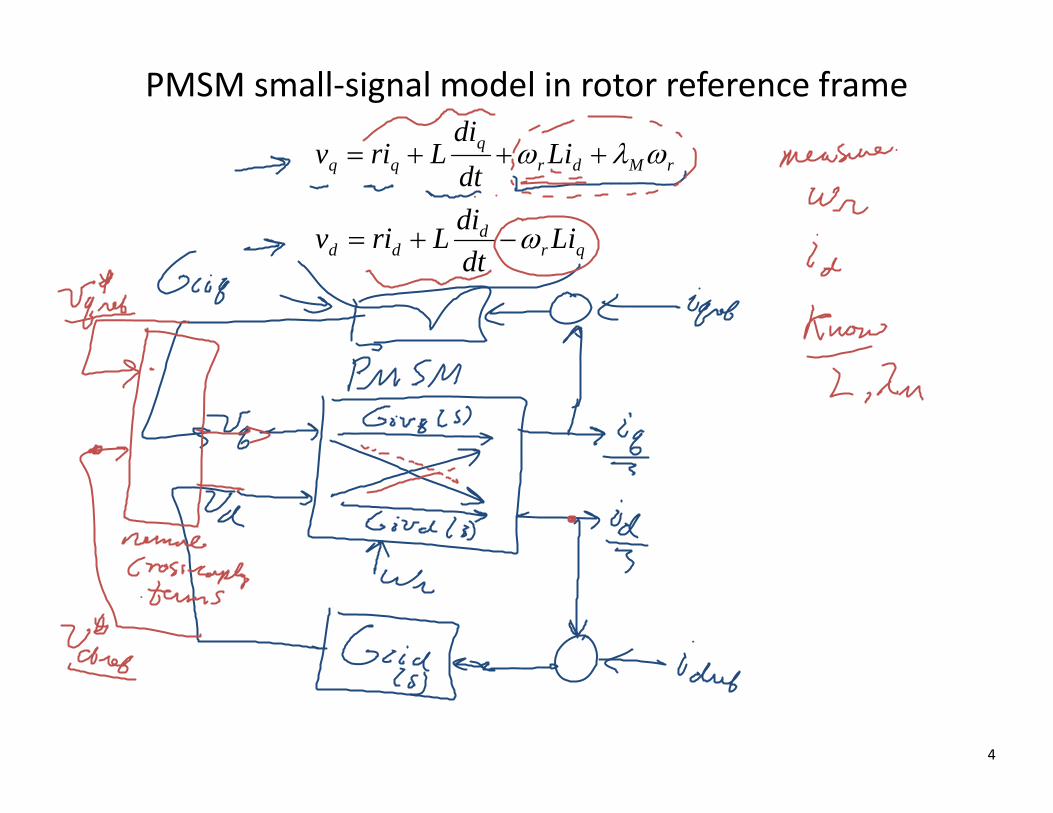
PMSM small‐signal model in rotor reference frame
4
rMdrq
qq Lidtdi
Lriv
qrd
dd LidtdiLriv

Current control loops
5
PMSMInverterFeedforward
Gciq(s)
Gcid(s)
vdref
vqref
vd
vq
v*dref
v*qref
id
iq
Idref
Iqref
rMdrqrefqref Livv *
qrdrefdref Livv *qr
ddd Li
dtdiLriv
rMdrq
qq Lidtdi
Lriv

Design of current control loops in rotor reference frame
6
dtdi
Lriv qqq *
dtdiLriv d
dd *

Current‐loop PI compensators
7
Gci(s)
v*qrefiq
Iqref
Giv(s)

Current‐loop PI compensators
8

Simulink implementation
9
5
vd
4
vq
3
id
2
iq
1
Tmlambda_m
lambda_m
0
idref
Vq voltage limit
Vd voltage limit
4/3/P/lambda_m
Torque reference to current reference
Product1
Product
L
L1
L
L
PI(s)
Iq compensator
PI(s)
Id compensator
3*P*lambda_m/4
GeneratedTorque
P/2
Gain2
v q
v d
wr
iq
id
Dynamic DQ Equations
Add
2
wrm
1
Tmref
Iqrefv qrev *
v dref *
v q
v d
rMdrqrefqref Livv *
qrdrefdref Livv *

Test of current controls in rotor reference frame
10
ECEB5017DQ current control
of PMSM
2*pi*1000/60
mechanicalspeed wrm
Torque referencecommand Tmref
Scope
Tmref
wrm
Tm
iq
id
v q
v d
DQ current controlled PMSM
Tmref
wrm
iq
id
iq_id
v q_v d
Tm
v q
v d
Torque

Numerical example
11
# of poles: P = 8
Peak torque: Tmmax = 240 Nm
Flux linkage M = 0.125 Vs
Phase resistance: r = 0.08
Phase inductance: L = 0.5 mH
DC bus voltage: Vbus = 500 V
Modern PMSMSpecific power: 1.5‐2 kW/kgPower density: 4‐6 kW/liter

Dynamic responses: step torque command
12
-200
-100
0
100
200
-300
-200
-100
0
100
200
300
0 0.1 0.2 0.3 0.4 0.5 0.6 0.7 0.8 0.9 1
-200
-100
0
100
200
0‐240 Nm step Torque commandnrm = 1000 rpm
TmTmref
iqid
vqvd

Dynamic responses: step torque command
13
0‐240 Nm step Torque commandnrm = 2740 rpm
-200
-100
0
100
200
-300
-200
-100
0
100
200
300
0 0.1 0.2 0.3 0.4 0.5 0.6 0.7 0.8 0.9 1
-200
-100
0
100
200
TmTmref
iqid
vqvd

Drive‐cycle example: 0‐60 mph‐0
14
Electric drive parameters:# of poles: P = 4Maximum torque: Tmmax = 200 NmMaximum current amplitude: 533 AFlux linkage M = 0.125 VsPhase resistance: r = 0.04 Phase inductance: L = 0.5 mHCurrent‐loop BW: 10 HzDC bus voltage: Vbus = 600 V
Top-level model of EV for use in ECEN 5017 course. Driving cycle is a speed-vs-time profile for the vehicle, operating on flat road. Driver uses torque command (gas & brake
pedals) to follow the reference speed.
Top-Level EV Model
m
Vref
speedsForces
Pdist
SOCIinvIbat
VbatvabciabcTm
iqd0vqd0dabc
Unit Conversion
Scope1
Scope
Electric VehicleDriver model
Driving cycleReference Speed
Vehicle Speed
Torque command(gas & brake pedals)

Vehicle Systems
15
Vehicle Systems ModelModel for a sample vehicle system during driving cycle.
4Electrical Signals
3Tm
2theta_rm
1Fdrive
Tire
OLD
SOC-only EV Battery Memory
[EDsigs]
Goto4
[Iinv]
Goto3
[Ibat]
Goto2
[Vbat]
Goto1
[SOC]
Goto
Gearing
2
Gain
[EDsigs]
From4
[Iinv]
From3
[Ibat]
From2
[SOC]
From1
[Vbat]
From
Electric Drive
DC-DC Converter
50
Constant
2Tcommand
1Vev
Battery Voltage
Battery Current
BatterySOC
DC Bus Voltage
Motor Torque
Wheel Torque
Wheel Angular Speed
Rotor Angular Speed
Inverter Input Current / DC-DC Output Current
rotor position
DC Bus Voltage

Electric Drive
16
5Vs
4I_DC
2theta_rm
1Tm
va
vb
vc
wrm
theta_rm
Tm
iabc
vqd0
PMSM
[Vbus]
Goto5
[iqd0]
Goto4
[vqd0]
Goto3
[iabc]
Goto2
[vabc]
Goto1
[dabc]
Goto
Tmref
theta_rm
iabc
wrm
Vabc*
iqd0
Vs
DQ Controller
Vg
Vref
Iout
Vout
Iin
dabc
3-Phase BuckAveraged Model
3V_DC2
Tcommand1
1wrm
wrm
rotor position
rotor position
Motor Torquevabc
iabc
iabc
Tmref

17
0 50 100 150 200 250 300 350 400 450 5000
20
40
60
80
Spe
ed [
mph
]
Reference Speed
Vehicle Speed
0 50 100 150 200 250 300 350 400 450 500-200
-100
0
100
200T
orqu
e [N
m]
Motor Torque
0 50 100 150 200 250 300 350 400 450 500-1000
-500
0
500
1000
Rot
or R
ef.
Frm
. C
urre
nts
[A]
iqidi0
0 50 100 150 200 250 300 350 400 450 500-200
-100
0
100
200
300
Rot
or R
ef.
Frm
. V
olta
ges
[V]
vq
vd
v0

18
0 50 100 150 200 250 300 350 400 450 500-400
-200
0
200
400
Pha
se V
olta
ges
[V]
va
vb
vc
0 50 100 150 200 250 300 350 400 450 500-200
-100
0
100
200
300R
otor
Ref
. F
rm.
Vol
tage
s [V
]
vq
vd
v0
0 50 100 150 200 250 300 350 400 450 500-1000
-500
0
500
1000
Rot
or R
ef.
Frm
. C
urre
nts
[A]
iqidi0
0 50 100 150 200 250 300 350 400 450 500-1000
-500
0
500
1000
Pha
se C
urre
nts
[A]
iaibic

19
0 50 100 150 200 250 300 350 400 450 5000
20
40
60
80
Spe
ed [
mph
]
Reference Speed
Vehicle Speed
0 50 100 150 200 250 300 350 400 450 500-200
-100
0
100
200
Tor
que
[Nm
]
Motor Torque
0 50 100 150 200 250 300 350 400 450 500-400
-200
0
200
400
Pha
se V
olta
ges
[V]
va
vb
vc
0 50 100 150 200 250 300 350 400 450 500-0.5
0
0.5
1
1.5
Pha
se D
uty
Cyc
les
da
db
dc

20
249.8 250 250.2 250.4 250.6 250.8 2510
20
40
60
80
Spe
ed [
mph
]
Reference Speed
Vehicle Speed
249.8 250 250.2 250.4 250.6 250.8 251-200
-150
-100
-50
0
50
Tor
que
[Nm
]
Motor Torque
249.8 250 250.2 250.4 250.6 250.8 251-600
-400
-200
0
200
Rot
or R
ef.
Frm
. C
urre
nts
[A]
iqidi0
249.8 250 250.2 250.4 250.6 250.8 251-100
0
100
200
300
Rot
or R
ef.
Frm
. V
olta
ges
[V]
vq
vd
v0

21
249.8 250 250.2 250.4 250.6 250.8 251-400
-200
0
200
400
Pha
se V
olta
ges
[V]
va
vb
vc
249.8 250 250.2 250.4 250.6 250.8 251-100
0
100
200
300
Rot
or R
ef.
Frm
. V
olta
ges
[V]
vq
vd
v0
249.8 250 250.2 250.4 250.6 250.8 251-600
-400
-200
0
200
Rot
or R
ef.
Frm
. C
urre
nts
[A]
iqidi0
249.8 250 250.2 250.4 250.6 250.8 251-1000
-500
0
500
1000
Pha
se C
urre
nts
[A]
iaibic

22
249.8 250 250.2 250.4 250.6 250.8 2510
20
40
60
80
Spe
ed [
mph
]
Reference Speed
Vehicle Speed
249.8 250 250.2 250.4 250.6 250.8 251-200
-150
-100
-50
0
50
Tor
que
[Nm
]
Motor Torque
249.8 250 250.2 250.4 250.6 250.8 251-400
-200
0
200
400
Pha
se V
olta
ges
[V]
va
vb
vc
249.8 250 250.2 250.4 250.6 250.8 251-0.5
0
0.5
1
1.5
Pha
se D
uty
Cyc
les
da
db
dc

23
250.03 250.04 250.05 250.06 250.07 250.08 250.09 250.154
56
58
60
Spe
ed [
mph
]
Reference Speed
Vehicle Speed
250.03 250.04 250.05 250.06 250.07 250.08 250.09 250.1-20
-10
0
10
20
Tor
que
[Nm
]
Motor Torque
250.03 250.04 250.05 250.06 250.07 250.08 250.09 250.1-40
-20
0
20
40
Rot
or R
ef.
Frm
. C
urre
nts
[A]
iqidi0
250.03 250.04 250.05 250.06 250.07 250.08 250.09 250.1-50
0
50
100
150
Rot
or R
ef.
Frm
. V
olta
ges
[V]
vq
vd
v0

24
250.03 250.04 250.05 250.06 250.07 250.08 250.09 250.1-200
-100
0
100
200
Pha
se V
olta
ges
[V]
va
vb
vc
250.03 250.04 250.05 250.06 250.07 250.08 250.09 250.1-50
0
50
100
150
Rot
or R
ef.
Frm
. V
olta
ges
[V]
vq
vd
v0
250.03 250.04 250.05 250.06 250.07 250.08 250.09 250.1-40
-20
0
20
40
Rot
or R
ef.
Frm
. C
urre
nts
[A]
iqidi0
250.03 250.04 250.05 250.06 250.07 250.08 250.09 250.1-40
-20
0
20
40
Pha
se C
urre
nts
[A]
iaibic

25
250.03 250.04 250.05 250.06 250.07 250.08 250.09 250.154
56
58
60
Spe
ed [
mph
]
Reference Speed
Vehicle Speed
250.03 250.04 250.05 250.06 250.07 250.08 250.09 250.1-20
-10
0
10
20
Tor
que
[Nm
]
Motor Torque
250.03 250.04 250.05 250.06 250.07 250.08 250.09 250.1-200
-100
0
100
200
Pha
se V
olta
ges
[V]
va
vb
vc
250.03 250.04 250.05 250.06 250.07 250.08 250.09 250.10.2
0.4
0.6
0.8
1
Pha
se D
uty
Cyc
les
da
db
dc

26
269.96 269.98 270 270.02 270.04 270.06 270.08 270.10
0.5
1
1.5
2
Spe
ed [
mph
]
Reference Speed
Vehicle Speed
269.96 269.98 270 270.02 270.04 270.06 270.08 270.1-11.4
-11.3
-11.2
-11.1
-11
-10.9
Tor
que
[Nm
]
Motor Torque
269.96 269.98 270 270.02 270.04 270.06 270.08 270.1-40
-30
-20
-10
0
Rot
or R
ef.
Frm
. C
urre
nts
[A]
iqidi0
269.96 269.98 270 270.02 270.04 270.06 270.08 270.10
1
2
3
Rot
or R
ef.
Frm
. V
olta
ges
[V]
vq
vd
v0

27
269.96 269.98 270 270.02 270.04 270.06 270.08 270.1-4
-2
0
2
4
Pha
se V
olta
ges
[V]
va
vb
vc
269.96 269.98 270 270.02 270.04 270.06 270.08 270.10
1
2
3
Rot
or R
ef.
Frm
. V
olta
ges
[V]
vq
vd
v0
269.96 269.98 270 270.02 270.04 270.06 270.08 270.1-40
-30
-20
-10
0
Rot
or R
ef.
Frm
. C
urre
nts
[A]
iqidi0
269.96 269.98 270 270.02 270.04 270.06 270.08 270.1-40
-20
0
20
40
Pha
se C
urre
nts
[A]
iaibic

28
269.96 269.98 270 270.02 270.04 270.06 270.08 270.10
0.5
1
1.5
2
Spe
ed [
mph
]
Reference Speed
Vehicle Speed
269.96 269.98 270 270.02 270.04 270.06 270.08 270.1-11.4
-11.3
-11.2
-11.1
-11
-10.9T
orqu
e [N
m]
Motor Torque
269.96 269.98 270 270.02 270.04 270.06 270.08 270.1-4
-2
0
2
4
Pha
se V
olta
ges
[V]
va
vb
vc
269.96 269.98 270 270.02 270.04 270.06 270.08 270.10.495
0.5
0.505
0.51
Pha
se D
uty
Cyc
les
da
db
dc

Electric Drive Modeling and Control Conclusions
29
• PMSM dynamic model in rotor reference frame removes retains all dynamics but removes the need to look at angle dependences
• In steady state, rotor reference frame voltages and currents are all DC• Techniques used to extent speed range:
• DC bus voltage control using the Boost DC‐DC converter • Field‐weakening using the direct component of the current
• Modern electric drives employ “vector” or “field‐oriented” control techniques based on the dynamic model in rotor reference frame
• Typical control systems includes inner current control loops that take advantage of the fact that torque produced is directly proportional to the quadrature component of the current
• 3‐phase inverters = 3 Buck converter legs, modulated to produce stator voltages necessary to generate requested stator currents. Voltage amplitude limited by the DC bus voltage. Typical switching frequency: kHz – 10’s kHz.
• Hierarchical modeling and control techniques• Switching transitions in the inverter or Boost DC‐DC converter: < s
• Switching period: 10’s of s
• Converter dynamics and current control loops: 10’s of ms
• Vehicle dynamics and drive cycles: seconds to minutes