to r. ti 12 edt/ecn msin - digital library/67531/metadc792691/m2/1/high... · ccb ctc dwk...
TRANSCRIPT
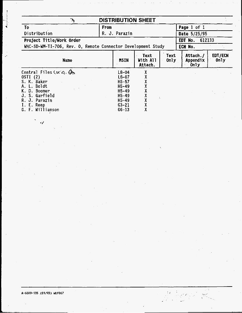
3% DISTRIBUTION SHEET To From Page 1 o f 1 Distribution R. J. Parazin Date 5/25/95 Project T i t l e/Work Order WHC-SD-WM-TI-706, Rev. 0 , Remote Connector Development Study 12 1;: 612133
Central Files (w'q, ts OSTI (2) S. K. Baker A. L. Boldt K. D. Boomer J. S. Garfield R. J. Parazin I. E. Reep G. F. Williamson
L8-04 L8-07 H5-57 H5-49 H5-49 H5-49 H5-49 63-21 66-13
Text Text Attach. / EDT/ECN Name MSIN With All Only Appendix Only
Attach. On1 y X X X X X X X X X
A-6000-135 (01/93) UEF067

DISCLAIMER
Portions of this document may be illegible in electronic image products. Images are produced from the best available original document.

Paoe 1 of 1 l.mT N? 612133
MAY Isg5 ENGINEERING DATA TRANSMITTAL
2. To: (Receiving Organization) I 3. From: (Originating Organization)
LLW Program Process Design 5. Proj./Prog./Dept./Div.: 6. Cog. Engr.:
TWRS R. 3. Parazin 74620/D3 023 8. Originator Remarks:
This document was prepared by Fluor Daniel, Inc.
11. Receiver Remarks:
15. DATA TRANSMITTED (A) (C) (D)
Sheet Rev. Item No. No. No.
(El Title or Description of Data Transmitted (Bl Document/Drawing No.
3 WHC-SD-WM-TI-706 0 Remote Connector Devel oment Studv
I I I I 16 KFY
4. Related EDT No.:
NA 7. Purchase Order No.:
9. Equip./Component No.: " : L
10. System/Bldg./Facility:
12. Major Assrn. Dwg. No.:
13. Perrnit/Permit Application No.:
14. Required Response Date: N / A
(F) I (GI ( H I i :r) Approval Reason Ongi- Receiv-
Desig- for nator nator Trans- Dispo- Dispo-
rnittal sition sition I I
3
(see WHC-CM-3-5, 5. Post-Review 2. Approved wlcomment 5. Reviewed wlmmment
(J) Name (K) Signature (Ll Date (M) MSIN
ed w/comnents
BD-7400-172-2 (04/94) GEF097
BD-7400-172-1
. .
RELEASE AUTHORIZATION
Document Number: WHC-SD-WM-TI-706, Rev. 0 ~
Document Title: REMOTE CONNECTOR DEVELOPMENT STUDY
Release Date: 5 /30/95
This document was reviewed following the procedures described in WHC-CM-3-4 and is:
APPROVED FOR PUBLIC RELEASE
WHC Information Release Administration Specialist:
0 C. Willingham 5/30/95
TRADEMARK DISCLAIMER. name, trademark, manufacturer, or otherwise, does not necessarily consti tute or imply i t s endorsement, recomnendation, or favoring by the United States Govermnt or any agency thereof o r i t s contractors or subcontractors.
This report has been reproduced from the best avaiLabLe copy. Available in paper copy and microfiche. Printed i n the United States of America. Available t o the U.S. Department o f Energy and i t s contractors from:
Reference herein t o any specif ic comnercial product, process, or service by trade
U.S. Department of Energy Off ice of Scient i f ic and Technical Information (OSTI) P.O. Box 62 Oak Ridge, TN 37831 Telephone: (615) 576-8401
Available t o the public from: U.S. Department of Comnerce National Technical Information Service (NTIS) 5285 Port Royal Road Springfield, VA 22161 Telephone: (703) 487-4650
A-6001-400.2 (09/94) WEF256 STER
SUPPORTING DOCUMENT 1. Total Pages z<
2. Title
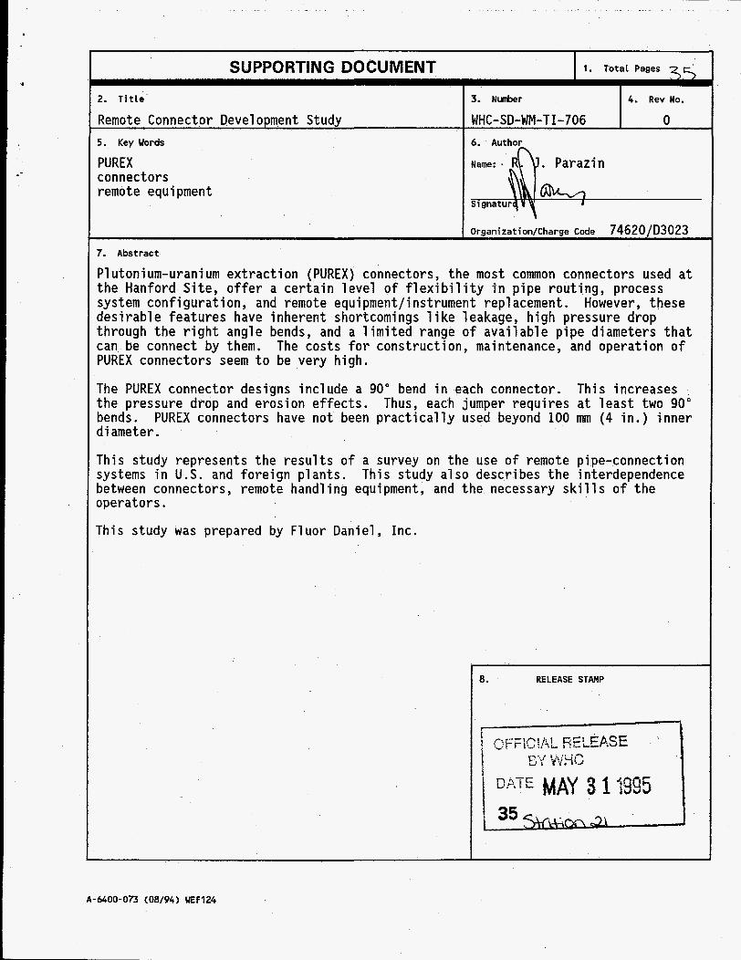
Remote Connector Development Study 5. Key Words
PUREX connectors remote equipment
3. Nunber 4. Rev No.
WHC-SD-WM-T 1-706 0 6. Author w S i gnatur
Organization/Charge Code 74620/D3023
N m : .
Plutonium-uranium extraction (PUREX) connectors, the most common connectors used at the Hanford Site, offer a certain level of flexibility in pipe routing, process system configuration, and remote equipment/instrument replacement. However, these desirable features have inherent shortcomings 1 i ke leakage, high pressure drop through the right angle bends, and a limited range o f available pipe diameters that can be connect by them. The costs for construction, maintenance, and operation of PUREX connectors seem to be very high.
The PUREX connector designs include a 90" bend in each connector. the pressure drop and erosion effects. bends. d i ameter .
This increases Thus, each jumper requires at least two 90"
PUREX connectors have not been practically used beyond 100 mm (4 in.) inner
This study represents the results of a survey on the use o f remote pipe-connection systems in U.S. and foreign plants. This study also describes the interdependence between connectors, remote handling equipment, and the necessary skills o f the operators.
This study was prepared by Fluor Daniel, Inc.
8. RELEASE STAMP
A-6400-073 (08/94) UEF124
WHC-SD-WM-TI-706 Revision 0
REMOTE CONNECTOR DEVELOPMENT STUDY
May 1995
Prepared by Fluor Daniel, Inc. Imine, California
For Westinghouse Hanford Company Richland, Washington
DISCLAIMER
This report was prepared as an account of work sponsored by an agency of the United States Government. Neither the United States Government nor any agency thereof, nor any of their employees, makes any warranty, express or implied, or assumes any legal liability or responsi- bility for the accuracy, completeness, or usefulness of any information, apparatus, product, or process disclosed, or represents that its use would not infringe privately owned rights. Refer- ence herein to any specific commercial product, process, or service by trade name, trademark, manufacturer, or otherwise does not necessarily constitute or imply its endorsement, recom- mendation, or favoring by the United States Government or any agency thereof. The views and opinions of authors expressed herein do not necessarily state or reflect those of the United States Government or any agency thereof.
I

WHC-SD-WM-TI-706 Revision 0
This page intentionally left blank.
ii

WHC-SD-WM-TI-706 Revision 0
CONTENTS
1 . 0
2.0
3.0
4.0
5.0
Objective and Scope . . . . . . . . . . . . . . . . . . . . . . . . . . . . . . . . . . . . . . 1.1 Background and Scope . . . . . . . . . . . . . . . . . . . . . . . . . . . . . . . . 1.2 Purpose and Need . . . . . . . . . . . . . . . . . . . . . . . . . . . . . . . . . . . summary . . . . . . . . . . . . . . . . . . . . . . . . . . . . . . . . . . . . . . . . . . . . . Technical Findings and Conclusions ............................ Description of Alternatives . . . . . . . . . . . . . . . . . . . . . . . . . . . . . . . . . . 4.1 Connectors . . . . . . . . . . . . . . . . . . . . . . . . . . . . . . . . . . . . . . .
4.1.1 General . . . . . . . . . . . . . . . . . . . . . . . . . . . . . . . . . . . . . 4.1.2 Hanford connector . . . . . . . . . . . . . . . . . . . . . . . . . . . . . . 4.1.3 PUREX connector . . . . . . . . . . . . . . . . . . . . . . . . . . . . . . 4.1.4 Three-bolt flange. Single-pipe connector . . . . . . . . . . . . . . . . . 4.1.5 Modified Idaho Connectors . . . . . . . . . . . . . . . . . . . . . . . . . 4.1.6 Cylinder/Trough Type Connector ..................... 4.1.7 Remote Graylock Connector . . . . . . . . . . . . . . . . . . . . . . . .
4.2 Remote Handling Systems .............................. 4.2.1 Remote Handling System Type 1 ..................... 4.2.2 Remote Handling System Type 2 . . . . . . . . . . . . . . . . . . . . . 4.2.3 Remote Handling System Type 3 . . . . . . . . . . . . . . . . . . . . . 4.2.4 Remote Handling System Type 4 . . . . . . . . . . . . . . . . . . . . .
4.1.8 Conventional Sleeve and Modified Conventional Sleeve . . . . . . .
4.2.5 General . . . . . . . . . . . . . . . . . . . . . . . . . . . . . . . . . . . . . Discussion of Alternatives . . . . . . . . . . . . . . . . . . . . . . . . . . . . . . . . . . 5.1 Process Flowsheet / Facility Design Impact . . . . . . . . . . . . . . . . . . .
5.2 Operability . . . . . . . . . . . . . . . . . . . . . . . . . . . . . . . . . . . 5.3 Maintainability 5.4 Maturity of Technology ...........................
. . . . . . . . . . . . . . . . . . . . . . . . . . . . . . . .
4 4 4 6 7 8 8 9
10 11 11 11 11 11 12 13
14 14 14 15 15
5.5 Schedule Impacts . . . . . . . . . . . . . . . . . . . . . . . . . . . . . . . 16 5.6 Regulatory Impacts .............................. 16 5.7 Safety . . . . . . . . . . . . . . . . . . . . . . . . . . . . . . . . . . . . . . 16 5.8 Capital Costs . . . . . . . . . . . . . . . . . . . . . . . . . . . . . . . . . 16
... 111
WHC-SD-WM-TI-706 Revision 0
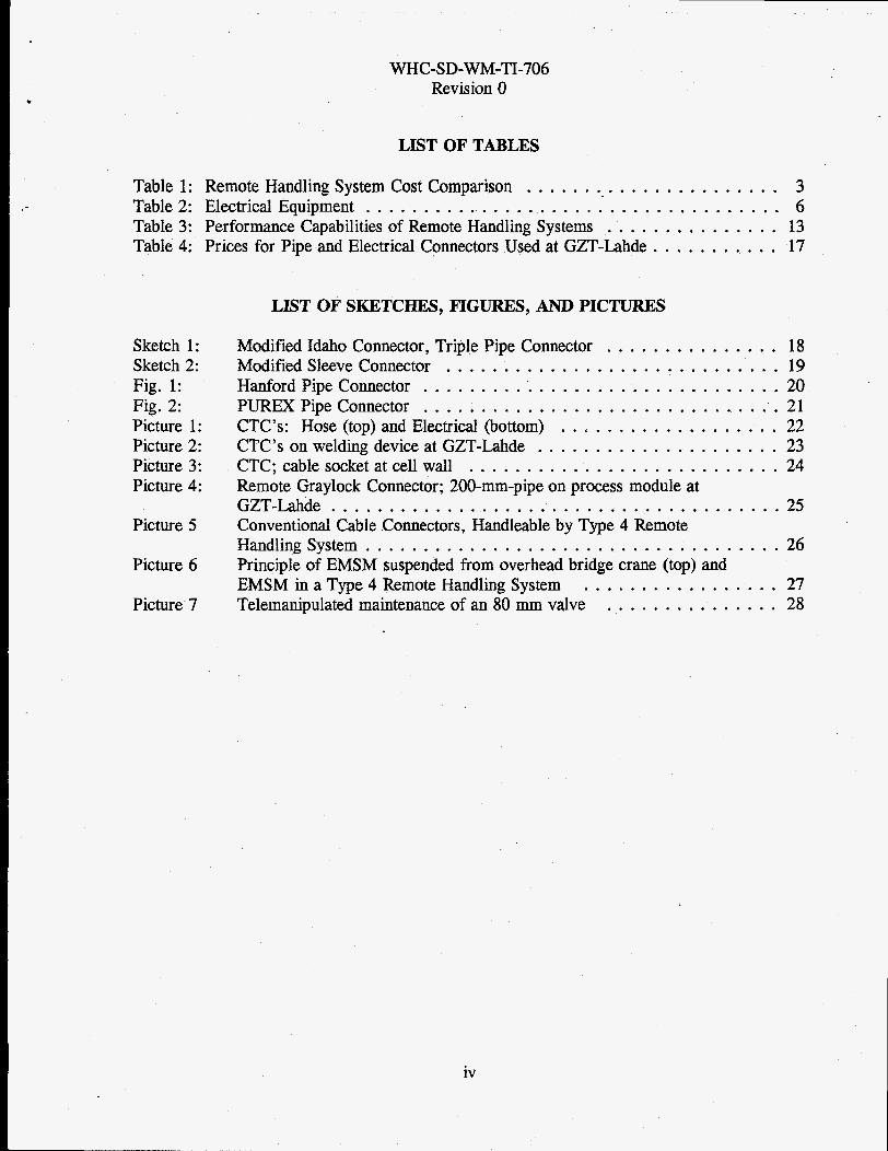
LIST OF TABLES
Table 1: Remote Handling System Cost Comparison . . . . . . . . . . . . . . . . . . . . . . 3 Table 2: Electrical Equipment . . . . . . . . . . . . . . . . . . . . . . . . . . . . . . . . . . . . 6 Table 3: Performance Capabilities of Remote Handling Systems . . . . . . . . . . . . . . . 13 Table 4: Prices for Pipe and Electrical Connectors Used at GZT-Lahde . . . . . . . . . . . . 17
LIST OF SKETCHES. FIGURES. AND PICTURES
Sketch 1: Sketch 2: Fig . 1: Fig . 2: Picture 1: Picture 2: Picture 3: Picture 4:
Picture 5
Picture 6
Picture’ 7
Modified Idaho Connector. Triple Pipe Connector . . . . . . . . . . . . . . . 18 Modified Sleeve Connector . . . . . . . . . . . . . . . . . . . . . . . . . . . . . 19 Hanford Pipe Connector . . . . . . . . . . . . . . . . . . . . . . . . . . . . . . . 20 PUREX Pipe Connector . . . . . . . . . . . . . . . . . . . . . . . . . . . . . . . 21 CTC’s: Hose (top) and Electrical (bottom) . . . . . . . . . . . . . . . . . . . 22 CTC’s on welding device at GZT-Lahde . . . . . . . . . . . . . . . . . . . . . 23 CTC; cable socket at cell wall . . . . . . . . . . . . . . . . . . . . . . . . . . . 24 Remote Graylock Connector; 200-mm-pipe on process module at GZT-Lahde . . . . . . . . . . . . . . . . . . . . . . . . . . . . . . . . . . . . . . . 25 Conventional Cable Connectors. Handleable by Type 4 Remote Handling System . . . . . . . . . . . . . . . . . . . . . . . . . . . . . . . . . . . . 26 Principle of EMSM suspended from overhead bridge crane (top) and EMSM in a Type 4 Remote Handling System . . . . . . . . . . . . . . . . . 27 Telemanipulated maintenance of an 80 mm valve . . . . . . . . . . . . . . . 28
iv

CCB
CTC
DWK
Elec,,.ical hand
EMM
EMSM
GZT-Lahde
INEL
KfK
KSNV
MIG
MTS
PAMELA
TEKO
TIG
WHC-SD-WM-TI-706 Revision 0
LIST OF TERMS AND ABBREVIATIONS
crosshead coupling bell (a remotely controllkd coupling device beneath a pulley block, which can take-in a cross-head-shaped short shaft.)
cylinder / trough-type connector
Deutsche Gesellschaft fiir Wiederaufarbeitung von Kernbrenn- stoffen (a utility owned German company for reprocessing of spent fuel and final storage of waste from production of electricity)
a motor activated mechanical gripper suspended from an overhead crane.
electro-mechanical manipulator
dual armed electro-mechanical master-slave manipulator
Groflzellen Teststand Lahde (large cell test facility Lahde; owned by DWK)
Idaho National Engineering Laboratory
Kernforschungszentrum Karlsruhe (Research institution in Germany)
kranbare Schwenk-Neige-Vorrichtung (counterweighted pan and tilt device supported by a crane hook; a steelyard-like horizontal manipulator)
metal inert gas welding technique
Manipulatortragers ystem (manipulator transport system; based on an overhead crane bridge)
DWK owned pilot plant for vitrification of high active waste
Technikum zur Komponentenerprobung (DWK owned test facility for extraction of Uranium)
Tungsten inert gas welding technique
V

trolley
WHC
WHC-SD-WM-TI-706 Revision 0
a wheeled carriage running on an overhead rail or track; here running on or below the girders of an overhead bridge crane.
Westinghouse Hanford Company
vi
WHC-SD-WM-TI-706 Revision 0
ffe
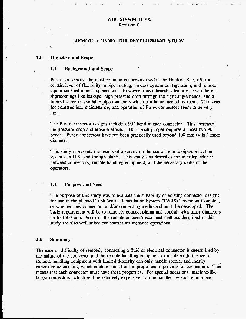
REMOTE CONNECTOR DEVELOPMENT STUDY
1.0 Objective and Scope
1.1 Background and Scope
Purex connectors, the most comm n cc ct rs used t the Ha ford Site, 1 certain level of flexibility in pipe routing, process system configuration, and remote equipment/instrument replacement. However, these desirable features have inherent shortcomings like leakage, high pressure drop through the right angle bends, and a limited range of available pipe diameters which can be connected by them. The costs for construction, maintenance, and operation of Purex connectors seem to be very high.
The Purex connector designs include a 90" bend in each connector. This increases the pressure drop and erosion effects. Thus, each jumper requires at least two 90' bends. Purex connectors have not been practically used beyond 100 mm (4 in.) inner diameter.
This study represents the results of a survey on the use of remote pipe-connection systems in U.S. and foreign plants. This study also describes the interdependence between connectors, remote handling equipment, and the necessary skills of the operators.
1.2 Purpose and Need
The purpose of this study was to evaluate the suitability of existing connector designs for use in the planned Tank Waste Remediation System (TWRS) Treatment Complex, or whether new connectors and/or connecting methods should be developed. The basic requirement will be to remotely connect piping and conduit with inner diameters up to 1500 mm. Some of the remote conneddisconnect methods described in this study are also well suited for contact maintenance operations.
2.0 summary
The ease or difficulty of remotely connecting a fluid or electrical connector is determined by the nature of the connector and the remote handling equipment available to do the work. Remote handling equipment with limited dexterity can only handle special and mostly expensive connectors, which contain some built-in properties to provide for connection. This means that each connector must have these properties. For special occasions, machine-like larger connectors, which will be relatively expensive, can be handled by such equipment.
1

WHC-SD-WM-TI-706 Revision 0
On the opposite extreme, slightly modified conventional connectors can be used with highly dexterous remote handling equipment. Thus, there is a trade-off between the cost of the remote handling equipment and the cost of the remote connectors..
Beyond the cost trade-off, highly dexterous remote handling equipment have other advantages. They can be used to perform freehand welding, plasma torch cutting, and other unexpected failure recovery-type operations. Low cost cables and hoses with relatively short lifetimes can be used in hostile environments since they are more readily replaced with highly dexterous equipment.
There is no best connector or best remote handling system. Simple economics does not favor either extreme. However, there are non-cost technical advantages to installing more dexterous remote handling equipment and there may be facility cost advantages allowed by simple connectors.
3.0 Technical Findings and Conclusions
Four alternative remote handling systems were considered in this study. They are, in order of least dexterous to most dexterous:
Type 1 Cost: $560,000 Bridge crane with dual hoists, one with an impact wrench
Type 2 cost: $800,000 Bridge crane with dual hoists, one with a counterweighted pan and tilt device (KSNV) mounted impact wrench
Type 3 Cost: $850,000 Bridge-mounted electro-mechanical manipulator (EMM) on a telescoping shaft with a separate hoist that contains an impact wrench
Type 4 cost: $1,800,000 Bridge crane with dual hoists, one with a KSNV mounted impact wrench and one with an EMSM.
Approximately 550 fluid jumpers and 200 electrical/instrument jumpers were identified in the detached, high source term, low-level vitrification plant. Similar numbers are expected for the high-level vitrification plant, but much less are expected for the separationdpretreatment facility. It is reasonable to assume that half this number of jumpers are serviced by a single remote handling system. Since each jumper has two connectors (a connector consists of a male and a female part), approximately 550 fluid connectors and 200 electrical connectors must be purchased for each remote handling system. The complexity, and therefore the cost, of connectors varies with the type of remote handling system available to service them. At
2
WHC-SD-WM-TI-706 Revision 0
Remote Handling Equipment
550 Fluid Connectors
200 Elect Connectors
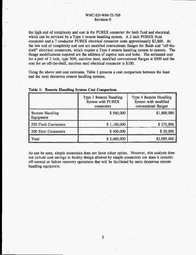
the high enb of complexity an^ cost is the PUREX connector for both fluid and electrical, which can be serviced by a Type 1 remote handling system. A 2 inch PUREX fluid connector and a 7 conductor PUREX electrical connector costs approximately $2,000. At the low end of complexity and cost are modified conventional flanges for fluids and "off-the- shelf" electrical connectors, which require a Type 4 remote handling system to operate. The flange modifications required are the addition of captive nuts and bolts. The estimated cost for a pair of 2 inch, type 304L stainless steel, modified conventional flanges is $500 and the cost for an off-the-shelf, stainless steel electrical connector is $100.
Type 1 Remote Handling System with PUREX
Type 4 Remote Handling System with modified
connectors conventional flanges
$560,000 $1,800,000
$ 1,100,000 $275,000
$400,000 $20,000
Using the above unit cost estimates, Table 1 presents a cost comparison between the least and the most dexterous remote handling systems.
Total I $ 2,060,000 I $2,095, OOO
As can be seen, simple economics does not favor either option. However, this analysis does not include cost savings in facility design allowed by simple connectors nor does it consider off-normal or failure recovery operations that will be facilitated by more dexterous remote handling equipment.
3

WHC-SD-WM-TI-706 Revision 0
4.0 Description of Alternatives
4.1 Connectors
4.1.1 General
In principle, connections can be made disengagable or not disengagable. Disengagable means, that the established joint can be opened by moving structural elements, Le. bolts, nuts, clamps, wedges, etc. Disengagable does not imply that a disengagable connector will be opened more than one time.
Three generic methods of connecting fluid piping together are available.
Simply press the two surfaces together (flange or swage type).
Use a coupling to bridge over the gap between both pieces (threaded coupling).
Fuse the material together (welding).
Due to the difficulty of fabricating pieces with surfaces which match the accuracy necessary for the first method, gaskets are normally used. The most preferred kind of surface is the plane, but cones, spherical, and parabolic surfaces are also used, though they are more difficult to shape and need more precise alignment to be coupled successfully.
A successful alternative to overcome the problem of machining cones that fit precisely is to use male cones with sharp wedges and smaller cone angles than the female cones have. The sharp wedges adapt to the female cones and provide for medium tightness even if misaligned by a small angle (swage-type connectors).
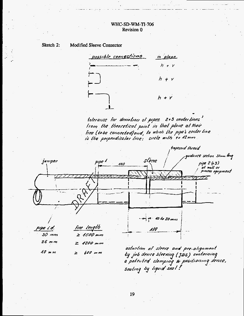
The use of sleeves for connections, according to the second method presupposes that the pieces to be connected can be or are threaded, and that they can be moved axially along their common center line for the length of the thread. These connectors normally use ductile tapes or self-hardening liquids for sealing of the threads.
Closure-enforcing elements for flange-type connectors in conventional industry are typically nuts and bolts. The closure elements for sleeve-type connection are the threads on the two pipes to be connected and the thread in the sleeve. During closing, closure-enforcing elements should not have any alignment functions but should only provide only for closhg the gap between the surfaces to be connected.
4
*.
WHC-SD-WM-TI-706 Revision 0
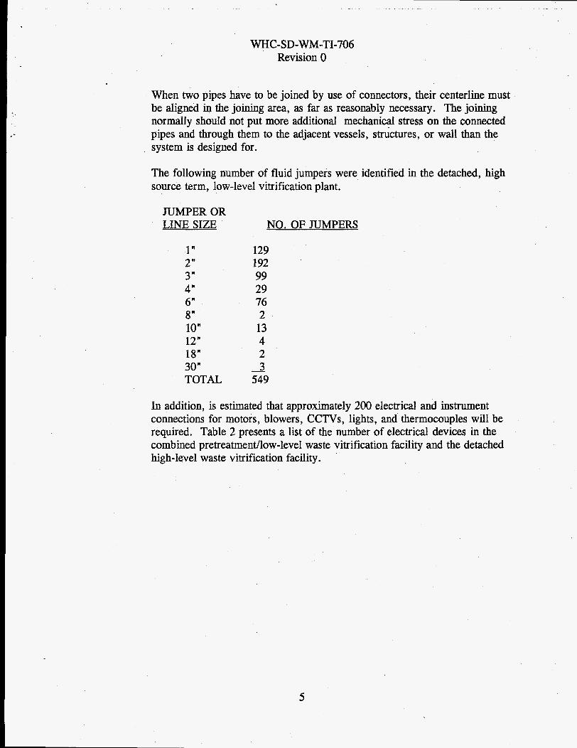
When two pipes have to be joined by use of connectors, their centerline must be aligned in the joining area, as far as reasonably necessary. The joining normally should not put more additionaI mechanical stress on the connected pipes and through them to the adjacent vessels, skctures, or wall than the system is designed for.
The following number of fluid jumpers were identified in the detached, high source term, low-level vitrification plant.
JUMPER OR LINE SIZE
1" 2" 3" 4" 6" 8" 10" 12" 18" 30" TOTAL
NO. OF JUMPERS
129 1 92 99 29 76 2 13 4 2 3
549 -
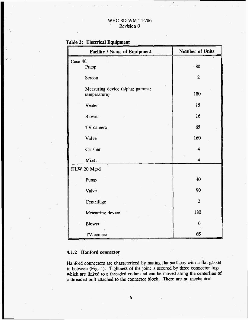
In addition, is estimated that approximately 200 electrical and instrument connections for motors, blowers, CCTVs, lights, and thermocouples will be required. Table 2 presents a list of the number of electrical devices in the combined pretreatmedlow-level waste vitrification facility and the detached high-level waste vitrification facility.
5
WHC-SD-WM-TI-706 Revision 0
Table 2: Electrical Equbment
Facilitv / Name of Eaubment
Case 4C Pump
Screen
Measuring device (alpha; gamma; temperature)
Heater
Blower
TV-camera
Valve
Crusher
Mixer
HLW 20 Mg/d
Pump
Valve
Centrifuge
Measuring device
Blower
TV-camera
4.1.2 Hanford connector
Number of Units
80
2
180
15
16
65
160
4
4
40
90
2
180
6
65
Hanford connectors are characterized by mating flat surfaces with a flat gasket in between (Fig. 1). Tightness of the joint is secured by three connector lugs which are linked to a threaded collar and can be moved along the centerline of a threaded bolt attached to the connector block. There are no mechanical
6

WHC-SD-WM-TI-706 Revision 0
guides to prevent misalignment or an unevenly loaded gasket, which may result in leaking. Gaskets made from materials whichtake a permanent set may eventually leak since the gaskets are subjected-to the full compressive load when the joint is made. The 90' bend are made by drilling two holes in the connector block. Erosion and high pressure drop can result at high flow rates.
4.1.3 PUREX connector
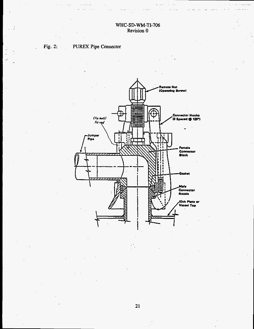
PUREX connectors are characterized by spherical mating surfaces on the female connector block and on the male connector nozzle, with a gasket in between (Fig. 2). Tightness of the joint is secured by three connector lugs which are linked to a threaded collar and can be moved along the centerline of a threaded bolt connected to the connector block. In the original design, the gasket was put in a recess of the female connector and its contact to the male connector nozzle was on the spherical surface.
The original design of this connector was prone to gasket leaks due to high compressive loads, as was found with the Hanford connector. It was re-designed in 1994, basically by replacing the gasket with an O-ring and allowing for metal-to-metal contact between the connector block and connector nozzle. This greatly limited the compressive loads and the potential for leakage due to a permanent set.
The 90" bend is made by a core in the casting which is used for the connector block. This bend is smoother than in the Hanford connector but is still subject to erosion and is the source of high pressure drops.
In March and April 1994 Kaiser Engineering Company Hanford prepared preliminary drafts of female connector parts to replace the above described connector blocks (see drawings ER5381-L1 through ER5381-L6). Six different Kaiser PUREX connector parts are shown. All of them avoid the 90" bend in the block. In concepts no. 1 through no. 3 the connector lugs are linked to a plate which can be moved along the centerline of the block for closing or opening the connection. The moving plate is carried by three threaded shafts. In concept no. 1 only one of these shafts has a hexagonal head for propulsion of the nut by an impact wrench. The other two shafts are propelled by a connecting chain. No. 2 and no. 3 discern from no. 1 in so far, as they have three shafts with hexagonal heads for propulsion which are connected by geared rings. No. 1 through no. 3 have in common, that they are made of more single parts than the original PUREX connectors, and that the assembly needs precise work for adjustment of the tiny single parts.
7

WHC-Sd-WM-TI-706 Revision 0
Concept no. 4 shows a connector which has only one, but stronger threaded shaft for movement and alignment of the lug carrying plate. In this case the shaft has to carry the bending movement which comes from the lug on the other side of the block.
Concept no. 5 shows a connector which uses a helical spring to hold the lug carrying plate in a position which closes the connector. This connector needs an remote handling equipment to move the lug carrying plate to the iug-open- position for making or opening connections. The closing force is certainly determined by the helical spring.
Concept no. 6 shows a combination of no. 4 and no. 5 . The helical spring provides the closing force , while the two fingers on the spindle shaft are used to squeeze the spring for opening and closing of the connection.
4.1.4 Three-bolt flange, Single-pipe connector
Single-pipe connectors consist of two high-pressure flanges joined by three bolts. One of them, the free flange, has a guide pin. The fixed flange has a mating guide hole and the bolts are secured in-the free flange by two threads. The nuts are attached to the backside of the fixed flanges in cages which are open to the top. The nuts can be replaced by use of a power manipulator. The gasket is attached to the free flange, and is in the compressive force transmission path when the flanges are bolted together. The connector itself has no bend, but the pipe it is welded to has a 90' bend to provide access to the bolt heads by the nut of an impact wrench.
4.1.5 Modified Idaho Connectors
Modified Idaho Connectors have been developed in Germany in the early 1980's for use in the reprocessing plant to be built at that time. They were tested at GZT-Lahde for handling, at TEKO in chemical process and in PAMELA during vitrification of high active waste. The modified Idaho single pipe connector is developed from what is known in the U.S. as a three-bolt flange. The other modified Idaho connector is a triple-pipe connector.
Modified Idaho connectors are machined and assembled with tolerances of about +/- 0.05 to 0.2 mm for all measurements which are important for the fit of surfaces to ensure tightness. Machining can easily be done with numeric controlled machines. Dimensions for threads, bolt, nuts, bores for penetration of bolts through flanges, and guiding pins of single pipe connectors have higher tolerances. This kind of connectors need a power manipulator to
8
WHC-SD-WM-TI-706 Revision 0
operate them.
The modification replaced the flat gasket with an O-ring for the single pipe connector and with swage fits for the triple-pipe connector. Modified Idaho connectors remained tight during tests on a bending machine. All bending tests were run to the breaking point of the pipes. Modified Idaho connectors do not have 90" bends, but the pipe, they belong to must have these bends to provide accessibility to the hexagonal bolt head. Modified Idaho connectors were used only for pipes which were used in transportation of gases and liquids and for maintaining of vacuum. They were not used for connection of cables or hoses.
4.1.5.1 Modified Single-Pipe Idaho Connector
Modified single-pipe Idaho connectors are in use for 30 mm ID to 80 mm ID pipes. Sketch 1 shows the typical characteristics of this connector: The gasket is put into a reset of the connector part B; the bolts are captive with sleeves; the free nuts are attached to the back side of connector part A, which is normally the fixed piece, by use of a disk bolted to that part.
4.1.5.2 Modified Triple-Pipe Idaho Connector
Modified triple-pipe Idaho connectors are used for pipes of 25 mm ID and smaller. More, but smaller pipes per connector can be joined, but that requires different design of the pipes routing close to the connector part B. Sketch 2 shows the typical characteristics of this connector: It uses a single bolt. The bolt is captive with a sleeve. The male cones of the swage are part of an insert which is put into a bore of the connector part B and fixed by a nut. They do not project over the surface of the flange thus eliminating damage during handling or connecting. The female conical bores are in inserts which project out of the connector part A and are secured by nuts. The main female thread is in a disk which is bolted to the back side of the connector part A.
4.1.6 Cylinder/Trough Type Connector
A spindle-driven coaxial cylinder/trough-type connector system (CTC), was developed by KfK/DWK and is also marketed by Remotec. The connector system can be used for connection of power cables and signal cables and for
9
I WHC-S D-WM-TI-706
Revision 0
connection of hoses to pipes and to hoses. An example is shown in picture 1.
CTCs with hoses are in use with 9 bar (127 psi) campressed air, for liquid nitrogen supply to freezing clamps, and for protective gas during remotely controlled pipe welding. Picture 2 shows an example of a welding device with transportation rest and cables and hose.
CTCs with cables are in use for connection of electrical devices to the controls and power supplies, and have been used for the connection of the manipulator transport system (MTS) at GZT-Lahde, for use in Wackersdorf. With an outer dimension of about 500 mm, this was the largest connector of its kind built to date.
In new plants, the "sockets" of these connectors can be mounted to the inside of cell walls. (See picture 3, Cable Socket With Triple-Pipe Modified Idaho Connectors). The sockets be connected to wires (or pipes, in case of transport of gases or liquids into or out of the cell) to a connection point on the other side of the cell wall. The wires are dedicated to the needs of just that equipment which will be used temporarily inside the cell, meaning, that different combinations of remote handling equipment (TV-cameras, etc.), one following the other, can be connected to these wall-mounted connectors.
4.1.7 Remote Graylock Connector
The remote Graylock connector is made of three ring-shaped, conical grooved parts, which are connected by two bolts and a spindle with right/left thread and hexagonal head. The spindle is directed transverse to the centerline of the pipes to be connected, and require flanges with conical shaped back sides. Tightness is provided by gaskets similar to those of the modified Idaho
' connectors. The remote Graylock connector itself is attached to that pipe which is free, meaning that it is not fixed to a wall or large process equipment.
Remote Graylock connectors for pipes with inner diameters from 100 mm to 200 mm have been tested on a bending machine and proved to be medium tight, even when the pipes broken. They were opened and closed in extended repetitive remote handling tests, used in real process equipment under process conditions in TEKO , and they were used in PAMELA. All tests and uses proved tightness of the connections. Picture 4 shows two 200-mm-pipe-jumpers with remote Graylock connectors at GZT-Lahde. They were used for 130 'C water supply and return of the cooler water after heat exchange.
10
WHC-SD-WM-TI-706 Revision 0
4.1.8 Conventional Sleeve and Modified Conventional Sleeve
It also became possible to use conventional and modified conventional sleeved pipe connections by employing clamping and positioning means for pipes with inner diameters up to 80 mm. These conventional sleeves and modified conventional sleeves allow for only 200 mm distance from centerline to centerline of neighbored 80-mm-pipes.
4.2 Remote Handling Systems
Four, increasingly dexterous types of remote handling systems have been identified.
4.2.1 Remote Handling System Type 1
This system consists of a bridge crane with dual hoists, one with an impact wrench. This is typical of the remote handling equipment that has been used at Hanford.
4.2.2 Remote Handling System Type 2
This system consists of a bridge crane with dual hoists, one with a counterweighted pan and tilt device, Kranbare Schwenk-Neige-Vorrichtung (KSNV) mounted impact wrench. The KSNV is a horizontal beam supported by a rotating crane hook. The working end can have tongs, a hook, or an impact wrench attached. It can reach approximately 2.5 m beyond the centerline of the crane hook. The opposite end contains a motorized counterweight. The weight can be towards or away from the center to counter balance the load on the working end. This system has been used in Germany.
Remotely controlled cutting and welding of pipes can be performed, albeit with much difficulty, with this type of remote handling equipment using specialized equipment.
4.2.3 Remote Handling System Type 3
This system consists of a bridge-mounted Electro-Mechanical Manipulator (EMM) on a telescoping shaft with a separate hoist that contains an impact wrench. The most popular EMM in the United States is manufactured by PaR Systems. EMMs have been used extensively at the Idaho National Engineering Laboratory and other national labs and international facilities.
11
WHC-SD-WM-TI-706 Revision 0
Pumps and valves installed in racks in Germany with pipe diameters up to 80 mm ID were maintained with an EMM. Larger pipes were possible but not necessary. Stirrers with shafts up to 1500 mm long were exchanged on vessels. Their cables and off-the-shelf remote plugs were handled. This remote handling system provides for installation of additional maintenance equipment by which, for example, pipes with diameters up to 100 mm ID can be remotely welded.
Jumpers with pipes of 200 mm ID (larger were not necessary) and two remote Graylock connectors were exchanged routinely successfully. (see picture 4) This remote handling system allows installation of the process equipment in a center-aisle type large cell. The rigid shafts, being carried by the overhead crane bridge can (and did) create safety problems inside the cell.
4.2.4 Remote Handling System Type 4
This system consists of a bridge crane with dual hoists, one with a KSNV mounted impact wrench and the other one with a dual armed Electro- mechanical or electro-hydraulic Master-Slave Manipulator (EMSM). An electro-mechanical model is available from a German company and an electro- hydraulic model is available from Schilling Development Corp. The EMSM is supported by a rotating hook. When performing operations, one arm is typically used to provide stability by grabbing onto the work piece or a structure while the other arm performs the operation. Having the whole unit supported from crane cables gives the operator visual feedback of horizontal forces. A parameter that is not available with a rigid mast manipulator like the EMM.
In Germany, special effort was directed to the development and testing of highly dexterous remote handling equipment for remotely controlled handling of equipment by carefully selected and trained teleoperators. Cost estimations showed that this method effectively reduces the cost of running and maintaining the facility, in which personnel access was restricted or impossible. It also provided the ability to work successfully and without using a mock-up in unknown and unstructured environments (e.g., post accident work).
Remotely controlled cutting and welding of pipes and telemanipulated freehand welding and plasma cutting can be performed with this type of remote handling equipment.
12

WHC-SD-WM-TI-706 Revision 0
4.2.5 General
Table 3 correlates the connectors and the remote handling systems.
Table 3: Performance Capabilities of Remote Handling Systems
0 connectors
13

WHC-SD-WM-TI-706 Revision 0
5.0 Discussion of Alternatives
5.1 Process Flowsheet / Facility Design Impact
Neither the connectors nor the remote handling equipment have any influence on the flow sheet, but they do influence the facility layout.
Remote handling system Type 1 is the same as those which are used with the canyons at Hanford ahd Savannah River. All process equipment can only be reached from the top. This requires installing the process equipment in canyon-like cells.
Remote handling system Type 2 adds horizontal reach and lift to the Type 1 system. This allows remote equipment to be mounted in racks or modules on top of each other. This design has the advantage of allowing a more compact remote module design. If these racks are put one besides the other alongside a wall, with a distance of about 1000 mm between them and the wall, disengagable connectors can be used on the top and on three sides of that rack. This provides for more freedom in pipe routing and positioning of process components which have to be maintained.
Remote handling system Type 3 adds stability and horizontal push capability to the qualities of remote handling system Type 2. This will allow the use of horizontal pump and valve jumpers like those used at INEL.
Remote handling system Type 4 is best described by picture 6. It allows for the widest freedom in facility design and allows the use both nuclear and conventional connectors for pipes, cables, and hoses. The process equipment can be of far-reaching conventional type.
5.2 Operability
The operability of connectors depends primarily on their size and the remote handling equipment available, and secondarily on the training of the operators.
In the GZT-Lahde test facility, large modules (3m x 3m x 12m racks with built-in process equipment) containing 36 jumpers each were disconnected, removed, then replaced and reconnected within a shift of eight hours using remote handling system Type 2 and highly trained operators. The connectors were modified Idaho connectors for pipes and CTCs for power and signal cables.
The time for opening the valve, shown in picture 7, cleaning the inside, replacing the gasket, putting the upper part back, and connecting it to the body was between three and four hours when only conventional tools were used with a remote handling system Type 4.
14

WHC-SD-WM-TI-706 Revision 0
No times are available for remotely controlled connecting and disconnecting of pipe connectors larger than for 200 mm ID pipes, though larger flanges have been connected by use of remote handling system Type 4.
5.3 Maintainability
Maintainability is a double edged sword. The more dexterous (and complex) the remote handling system, the easier it will be to maintain the facility. However, the more complex the remote handling equipment is, the more maintenance will be required on it. Type 1 remote handling equipment is the simplest of the four alternatives. Type 2 adds the maintenance requirements of a KSNV, but that is expected to be minimal. Types 3 and 4, because of their complexity, are expected to require significantly more maintenance time than either Type 1 or Type 2.
The type of remote connectors should not affect the maintainability of the facility.
5.4 Maturity of Technology
Hanford, PUREX and Idaho connectors are well known as proven technology. The reliability of the modified Idaho connectors, CTCs, and remote Graylock connectors was proven during harsh tests in KfK, GZT-Lahde, TEKO, and in PAMELA.
Modified conventional flanges and sleeves have not been used in practice, but based on test facility experience, they can be handled by remote handling system Type 4 equipment.
Conventional plug and socket connectors and conventional quick coupling connectors for cables and hoses can be used by the aid of remote handling system Type 4. Remote handling systems Types 2 and 3 can only handle connectors of this kind which are modified to their abilities.
Remote controlled orbital TIG welding of pipes up to 50 mm ID has been performed more than 5000 times using welding job devices (see picture 2). Pipes up to 150 mm ID can also be welded by this method. Though pipes above 25 mm ID can be welded by use of Type 2 or Type 3 remote handling system, it requires a Type 4 remote handling system to weld smaller pipes because only the EMSM provides the precision necessary for that fine of work.
15
WHC-SD-WM-TI-706 Revision 0
5.5 Schedule Impacts
There are no schedule impacts since there is no need for the development of remote handling equipment or connectors evaluated in this study.
5.6 Regulatory Impacts
There are no regulatory impacts due to connectors or remote handling equipment.
5.7 Safety
There are no safety risks from the connectors or remote handling equipment evaluated in this study.
5.8 Capital Costs
Table 3 presents costs for pipe and electrical connectors which were tested at the GZT-Lahde facility. The budget price for a 2-inch PUREX connector is $2,000 in 1994 dollars. The budget price for a 7-pin PUREX electrical connector is $2,O00 in 1994 dollars. Budget prices for remote handling equipment in 1993 dollars is as follows:
Overhead bridge crane, 5 tons capacity with 2 trolleys $560,000
0 KSNV; reach 2500 mm; carrying capacity 500 kg; $ 800,000
0 Electro-mechanical manipulator $ 850,000
0 Pair of EMSM’s; carrying capacity 45 kg per arm; $ 1,8oo,oO0
16
r
WHC-SD-WM-TI-706 Revision 0
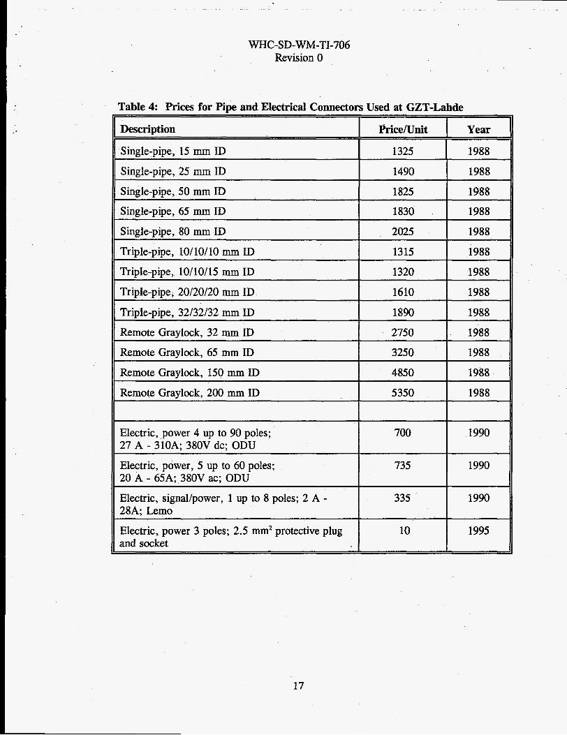
Table 4: Prices for Pipe and Electrical Connectors
Description
Single-pipe, 15 mm ID
Single-pipe, 25 mm ID
Single-pipe, 50 mm ID
Single-pipe, 65 mm ID
Single-pipe, 80 mm ID
Triple-pipe, 10/10/10 mm ID
Triple-pipe, 10/10/15 mm ID
Triple-pipe, 20/20/20 mm ID
Triple-pipe, 32/32/32 mm ID
Remote Graylock, 32 mm ID
Remote Graylock, 65 mm ID
Remote Graylock, 150 mm ID
Remote Graylock, 200 mm ID
Electric, power 4 up to 90 poles;
Electric, power, 5 up to 60 poles; 20 A - 65A; 380V ac; ODU
Electric, signal/power, 1 up to 8 poles; 2 A - 28A; Lemo
Electric, power 3 poles; 2.5 mm2 protective plug and socket
27 A - 310A; 380V dc; ODU
Used at GZT-Lahde
Price/Unit Year
1325 1988
1490 1988
1825 1988
1830 1988
2025 1988
1315 1988
1320 1988
1610 1988
1890 1988
2750 1988
3250 1988
4850 1988
5350 1988
700 1990
735 1990
335 1990
10 1995
17

. . .. ~.
-. . . .- - ..- ..... - .. . . .. - - . . . .
WHC-SD-WM-TI-706 Revision 0
Sketch 1: Modified Idaho Connector, Triple Pipe Connector tiange connector
I
18
WHC-SD-WM-TI-706 Revision 0
Sketch 2: Modified Sleeve Connector
19

. - .
Fig. 1:
WHC-SD-WM-TI-706 Revision 0
Hanford Pipe Connector
20
WHC-SD-WM-TI-706 Revision 0
Fig. 2: PUREX Pipe Connector
I
21

WHC-SD-WM-TI-706 Revision 0
Picture 1: CTC’s: Hose (top) and Electrical (bottom)
wall part
spindle drive
I
22

_ . . . . . . . . . . . . . . . -
- .- . - . . . . ... . . . . . _ _ _ . - - . . -. . ~- ..~_.I._ ~ ....._
WHC-SD-WM-TI-706 Revision 0
Picture 2: CTC’s on welding device at GZT-Lahde
23

Picture 3:
WHC-SD-WM-TI-706 Revision 0
CTC; cable socket at cell wall
24

Picture 4:
- . . . ~~. ..... - .. .. . . . . .- . . .. .
WHC-SD-WM-TI-706 Revision 0
Remote Graylock Connector; 200-mm-pipe on process module at GZT-Lahde
25
. .. .. . x . _I . - . . _. - . . . -- . . .. . - . .. .
WHC-SD-WM-TI-706 Revision 0
Picture 5 Conventional Cable Connectors, Handleable by Type 4 Remote Handling System
t
26

Picture 6
WHC-SD-WM-TI-706 Revision 0
Principle of EMSM suspended from overhead bridge crane (top) and EMSM in a Type 4 Remote Handling System
CCB with hook - the "ideal manipulatot'
pair of EMSMs
Y
27

Picture 7
. . ...
WHC-SD-WM-TI-706 Revision 0
Tefemanipulated maintenance of an 80 mm valve
:i
' i:
28