to my beloved wife, siti shairra zakaria, my children...
TRANSCRIPT


iii
To my beloved wife, Siti Shairra Zakaria, my children Nurul Asyikin, Mohd Amir Arif, Nurul Amira, Mohd Amir Afiq……….. ………………..thank you for your love, support and patience during this hard time.
I love you so much!! 7november2006

iv
ACKNOWLEDGEMENT
I would like to express my sincere appreciation and thousands of thank you to my project supervisor, Professor Madya Dr. Mohamad Ibrahim Mohammad for being patience with me, for his encouragement, guidance, critics, advice and motivation and last not least the valuable friendship.
While preparing this project, I was in contact with many people, academicians, and construction professionals in construction firm, consultants and suppliers. They have contributed towards my understanding and thoughts. In particular, I am also very thankful to all of them for their willingness to share their valuable knowledge, expertise and technical know-how which assist me a lot in preparing this project. Without their continued support and interest, this project would not have been the same as presented here.
I am also would like to thank all the lecturers who have conducted the course from the beginning and not hesitating to share their knowledge with us. I am grateful to all my family members who are very understanding and have been patience with me during my hard time. My fellow postgraduate students should also be recognized for their support. My sincere appreciation also extends to all my colleagues and others who have provided assistance at various occasions. Their views and tips are useful indeed. Unfortunately, it is not possible to list all of them in this limited space.
v
ABSTRACT
The bridge construction utilizing the concept of erecting the precast
segmental panel has been a chosen method for bridge construction within restricted
area. This method has been successfully exhibit the constructability within the urban
area and also crossing the wide water body, valley and existing highway or railroad.
The suitability of this method of construction is depending on the availability of
working space, which govern the major cause in selection of this construction
method. The aim and objective are to study the problem in the manufacturing the
segment and segment erection. This master project has studied the procedures in
construction of precast segmental box girder bridge by balance cantilever method
using the overhead gantry. This project also studied the segment manufacturing
procedures and discovers some problem problems faced in segment manufacturing
that is interesting and need to expose for awareness to the bridge professional. The
segment erection procedures and sequence also has been studied and the related
problems have been highlighted and need further study by the professional bridge
designers and constructors. The study has been conducted by direct structured
interview and questionnaire with the bridge expertise. The bridge professional from
consultants, segment manufacturer, main contractors and specialist sub contractor
have shared their knowledge, technical know-how and experience and has been
elaborated in details in this project. The finding is very interesting and it has exposed
the problem related to the segmental bridge construction that need further study by
the bridge expertise. This study also recommended some idea about working
concurrently and simultaneously without fragmentation that could lead to errors. It is
expected that by addressing the problem at early stage could assist the designer,
manufacturer and constructor to foresee the problem and find the mitigation
measures thus could eliminate the errors that may occurs in manufacturing the
segment and erection on site.

vi
ABSTRAK
Pembinaan jambatan menggunakan konsep pemasangan panel segmen
pratuang telah menjadi pilihan utama dalam pembinaan jambatan dikawasan tapak
yang terhad. Kaedah ini telah mepamirkan kebolehbinaan dalam kawasan bandar,
merentasi laluan air, lembah, dan laluan keretapi atau lebuhraya. Kesesuaian kaedah
ini bergantung kepada keadaan kawasan tapak kerja, yang menjadi faktor utama
dalam pemilihan kaedah ini. Tujuan dan objektif kajian kes ini adalah untuk
mengkaji masalah dalam pembuatan panel segmen pratuang dan pemasangan panel
tersebut. Projek Sarjana ini mengkaji prosidur pemasangan panel segmen pratuang
dengan kaedah Balance Cantilever menggunakan overhead gantry. Projek ini juga
mengkaji prosidur dalam pembuatan panel segmen pratuang dan telah menemui
beberapa masalah yang sangat menarik untuk dikaji dan perlu diumumkan kepada
pakar-pakar dalam pembinaan jambatan. Kaedah pemasangan juga telah dikaji dan
beberapa masalah telah dibangkitkan dan perlu pemerhatian dari pakar-pakar bidang
jambatan. Kajian telah dijalankan secara temuduga yang terancang dan soal-selidik
dengan pakar-pakar jambatan. Pakar-pakar jambatan dari pihak perunding, pembuat
panel segmen, kontraktor utama, kontraktor pakar dalam bidang jambatan dan pakar
dalam bidang pra-tegasan telah berkongsi kepakaran teknikal, pengetahuan dan
pengalaman masing-masing dalam projek Sarjana ini. Hasil kajian amat menarik
dan telah mendedahkan masalah yang berkaitan dan kajian lanjut perlu dibuat.
Projek ini juga telah mengemukakan beberapa cadangan kepada pihak-pihak yang
terlibat untuk membentuk kerjasama dalam satu pasukan tanpa pembahagian kerja
yang merumitkan Adalah diharapkan dengan mengenalpasti masalah diperingkat
awal dapat membantu pihak yang terlibat mengurangkan kesilapan dalam
pembuatan segmen dan pemasangannya.

vii
TABLE OF CONTENTS
CHAPTER TITLE PAGE
DECLARATION ii
DEDICATION iii
ACKNOWLEDGEMENTS iv
ABSTRACT v
ABSTRAK vi
TABLE OF CONTENTS vii
LIST OF TABLES xi
LIST OF FIGURES xiii
LIST OF APPENDIX xvii
1 INTRODUCTION
1.1 Background 1
1.2 Problem Statement 1
1.3 Objective 5
1.4 Scope and Limitation 5
1.5 Brief Research Methodology 6
1.6 Limitation of the Study 7
2 OVERVIEW OF PRECAST SEGMENTAL BOX GIRDER BRIDGE CONSTRUCTION

viii
2.1 Introduction 9
2.2 The Historical Background 10
2.3 The Adaptation of the Technology 12
2.4 The Advantages of Segmental Construction 13
2.5 The Disadvantages of Segmental Construction 17
2.6 Alternative Construction Methods 19
3 MANUFACTURING OF SEGMENTAL BOX GIRDER
3.1 Segmental Box Girder Production 26
3.2 The Concrete Segment 28
3.3 Segment Manufacturing 31
3.3.1 Fabrication of Reinforcement 31
3.3.2 Segment Mould 32
3.3.3 Casting of Segment 34
3.3.3.1 Shortline Match Casting 35
3.3.3.2 Longline Match Casting 35
3.3.4 Geometry Control during Casting 37
3.3.5 Rejection of Segment 38
3.3.6 Handling, Storage and Delivery 40
4 OVERHEAD GANTRY OPERATION AND SEGMENTERECTION
4.1 Introduction 43
4.2 Design of the Overhead Gantry 43
4.3 Assembly of the Gantry Launcher 44
4.4 Testing the Overhead Gantry 46
4.5 Segment Delivery 52
4.6 Erection of Segment 54

ix
4.6.1 Erection of Pier Segment 54
4.6.2 Erection of Expansion Joint 55 Segment at Expansion Joint Pier
4.7 Launching the Gantry 57
4.8 Epoxy Bonding Agent for Precast Segment 57
4.6.1 Mixing and Application of Epoxy 65
4.9 Stressing Works 68
4.9.1 Temporary Stressing 68
4.9.2 Cantilever Stressing 69
4.9.3 Continuity Stressing 69
4.9.4 Stressing Wire 70
4.10 Concrete Stitching 73
4.11 Tendon Grouting 74
5 RESEARCH METHODOLOGY
5.1 Introduction 78
5.2 Determination of Research Objective 78
5.3 Literature Review 79
5.4 Data Collections 79
5.4.1 Questionnaire Survey 79
5.4.2 Interview with the Experts 80
5.4.2.1 Objective of the Interview 81
5.4.2.2 Methodology of the Interview 81
5.5 Data Analysis 82
5.5.1 Content Analysis 82
5.5.2 Frequency Analysis 82

x
5.5.3 Relative Index Analysis 82
6 ANALYSIS AND FINDING
6.1 Introduction 84
6.2 Questionnaire Survey 85
6.2.1 Section A – Respondent Back 86 Ground
6.2.2 Section B - Manufacturing of 88 Segmental Box Girder
6.2.3 Section C – Erection of Segmental 95 Bridge
6.3 Analysis of the Structured Interview 102
7 DISCUSSION
7.1 Introduction 106
7.2 Manufacturing of Segment 107
7.3 Erection of Segment 108
7.4 New Invention 118
7.4.1 Transparent Sheath 118
7.4.2 Ducting Coupler 119
7.4.3 Stainless Steel Plated Strand 121
8 RECOMMENDATION AND CONCLUSION
8.1 The Recommendation 123
8.1.1 At Inception and Design Stage 123
8.1.2 At Segment Manufacturing Stage 126
8.1.3 At Construction Stage 127
8.2 Conclusion 128
REFERENCES 129

xi
APPENDICES 133
LIST OF TABLE
TABLE NO TITLE PAGE
2.1 FHWA Condition Ratings for Concrete Bridges 21
2.2 Segmental Concrete Bridge Inspection Report Summary 22
3.1 Segment dimension tolerances 29
4.1 Erection tolerances 60
4.2 Steel wire relaxation loss 72
4.3 Tendon anchorage 73
6.1 Number of respondents 86
6.2 Distribution of the expert respondents based on position 86
6.3 Distribution of Respondent based on experience in 87 bridge construction
6.4 Modification on segment as responded in questionnaire 91
6.5 Reinforcement most congested area in segment 91
6.6 Analysis of respond on the contribution factor 93 to problem in manufacturing the segment
6.7 Frequency analysis of the factor contribute to problem 94 in manufacturing the segment with Relative Index analysis
6.8 Checking on the pier capacity 96
6.9 Modification to pier column 97
6.10 Analysis of respond on the contribution factor to 100 problem in erection the segmental bridge
6.11 Frequency analysis of the factor contribute to 101

xii
problem in erection of segmental bridge with Relative Index analysis
6.12 Distribution of expertise for interview 102
6.13 Analysis of structured interview with expertise 103
6.14 Frequency analysis on the respond to interview 104
xiii
LIST OF FIGURES
FIGURE NO TITLE PAGE
1.1 Research methodology sequence 8
2.1 Nineteenth century cantilever bridge construction 13 (the Firth of Forth Bridge in Scotland)
2.2 Precast span-by-span construction with overhead truss 23 (the Spaghetti Bowl in Las Vegas, Nevada)
2.3 Cast-in-place span-by-span construction with self- 23 launching forms (Rosario Victoria Bridge in Argentina)
2.4 Incrementally launched deck for Neckarburg Arch 24 Bridge in Germany, 1977
2.5 Vietnam Veterans Memorial Bridge - cantilever 24 construction of a segmental box girder using traveling forms
2.6 Typical shape of box girder on pier for Subang Kelana 25 Link Project
3.1 Arrangement of the segment between intermediate piers 30
3.2 The rebar jig where the reinforcement is being fix 31
3.3 Reinforcement arrangement in the segment at the left 32 and right web area
3.4 Reinforcement at center web with blister 33
3.5 Schematic diagram for curing cell for SKL Project 36
3.6 Longline casting yard 36
3.7 Arrangement of the segment’s marking 38
3.8 Typical segment shape 39

xiv
3.9 Sand blasting to the match-cast surface of the segment 41
3.10 Straddle carrier being used to shift the segment within 42 casting yard
4.1 Typical gantry launching steps 45
4.2 Preparing the hardstand for gantry assembly near P13 and 47 P12 at Subang Kelana project
4.3 Part of the gantry being assembled at Bayan Baru bypass 47 Project
4.4 Schematic figure for step by step gantry assembly 49
4.5 Schematic figure for step by step gantry assembly 50
4.6 Schematic figure for step by step gantry assembly 51
4.7 Deflection checking point on the gantry truss 52
4.8 Load testing for the complete assembled gantry prior to 53 segment erection to a 1.5 factor of safety
4.9 Arrangement of segment delivery 53
4.10 Pier segment being arrange to be seated on the jacks 55
4.11 Schematic figure on the segment seating 55
4.12 Sequence of segment erection at expansion joint 58
4.13 Sequence of segment erection at intermediate piers 59
4.14 Launching step 1 & 2 61
4.15 Launching step 3 62
4.16 Launching step 4 62
4.17 Launching step 5 & 6 63
4.18 Launching step 7 63
4.19 Launching step 8 64
4.20 Mixing the epoxy bonding agent 66
4.21 Applying the epoxy onto the segment surface 67

xv
4.22 Temporary stressing using stress bar 69
4.23 The tendon stressing anchorage 70
4.24 Stressing step by step 71
4.25 Stressing in progress 71
4.26 Schematic diagram of the stitch 74
4.27 Stitch beam installed and stress to align the box girder 75
4.28 Concreting the stitch in progress 75
4.29 Typical arrangement of the tendon in prestress structure 76
6.1 Distribution of respondent based on position 87
6.2 Distribution of Respondent based on experience in bridge 88 construction for questionnaire
6.3 Distribution of respondent for interview 102
7.1 One of massive modification by contractor to cater for 111 extra construction load
7.2 Close up of the above at the middle and left of the segment 111
7.3 Transverse pre-stressing for one of the segment as design 112 by specialist contractor to cater for extra load
7.4 Pier segment temporarily seated on jacks. Load transferred 112 to pier eccentrically
7.5 Temporary blister at middle of segment for temporary 113 prestressing
7.6 Temporary blister at both left & right of the web for 113 temporary prestressing
7.7 The temporary staging for erection of half end of segment 114 at expansion joint pier design by contractor
7.8 The temporary staging from front view 115
7.9 Temporary nailing (tie down) pier segment to the pierhead 116
7.10 Transparent sheathing used for external tendon in Japan 119
7.11 The Liaseal Coupler 120

xvi
7.12 Schematic drawing of the Liaseal Coupler 120
7.13 Drawing illustrated cross-section details of Liaseal duct 121 Coupler
7.14 DSI Stainless steel plated strand 122

xvii
LIST OF APPENDICES
APPENDIX TITLE PAGE
A Questionnaires for the Thesis 133

1
CHAPTER 1
INTRODUCTION
1.1 Background
Bridge construction using the precast post tension segmental box girder is
considered a new trend in Malaysia. This method of construction started with
construction of Light Rail Transit (LRT) viaduct in 1997, post tension box girder
start to gain recognition as a preferred method of construction of bridge within the
urban area. This similar construction follows by construction of Second Link Bridge
to Singapore, Bayan Baru By-pass, Butterworth Offshore ring Road, several bridges
in Kuala Lumpur such as Ampang-Kuala Lumpur Elevated Highway, SPRINT
Highway, Kerinci Link, New Pantai Expressway, Subang Kelana Link and so on.
The constructed box girder bridge has been utilizing several methods such as Span-
by-Span, Balanced Cantilever and Incremental Launching. This master project
explores the process of manufacturing the segmental box girder and the
construction/erection of the post tension precasted segmental box girder bridge using
balance cantilever method.
1.2 Problem Statement
During the design stage, in normal practice, the main consultant design
normally will cater for permanent structure only. Any design for temporary work
such as temporary pre-stressing, segment modification, additional blister, check for
segment lifting, check for segment’s reinforcement for additional load, thickening of

2
top slab, etc, being carried out by the contractor and / or bridge specialist contractor.
The process of preparing shop drawing, review by consultant, resubmitting the
revised shop drawings, getting the shop drawing endorsed by Professional Engineer
always take a few round and time consuming before it could be approved and use for
manufacturing the segment.
During segment production at casting yard, the problems arise in fabricating
the mould and reinforcement. Due to short size of the segment, longitudinally, the
reinforcement become congested, the reinforcement may collide with the tendon
conduit and other insertions item. The reinforcement also clashes between them and
the gap is very close, make it limited access for concrete to fill up the formworks.
Wollman et. al. (2000) reported that the end diaphragm segment where the tendon is
anchored, which is also the Pier Segment always experience the cracks occurred.
One of the reason mentioned is due to detailing of the congested reinforcement
which limited the access of the concrete to compact, thus created a localise improper
and incomplete compaction to the concrete. This phenomenon created the crack
when stressing applied to the tendon.
FHWA (2005) in their Task Number 7.11 – Proper Detailing had addressed
the common problem in detailing of the segment that result in problem during
casting such as:
1. Reinforcing fit-up. Conflicts can occur at anchorages, blisters, deviation
beams and bearing diaphragms. The three-dimensional space requirements of
tendon anchors and spirals need to be accounted for. Reinforcing should be
arranged to accommodate horizontal and vertical tendon profiles. All
reinforcing bends with the actual curve radius should be drawn to scale.
2. Nodes. All tensile reinforcing entering a structural node (Strut & Tie design)
should be adequately developed. Post-tensioning bars require some distance
from the free, perpendicular edge to become developed; cover requirements,
bar extension, nut and plate thickness can combine to shift a node off of the
center of the neutral axis of an entering thin wall element (e.g. web or slab
entering a diaphragm).

3
3. Appurtenances. Details for access openings, drains, lighting fixtures etc. are
often presented as separate details at the end of a plan set. These too should
be drawn to scale with the reinforcing from typical plan sheets prior to final
plan preparation. In complex projects, fully-integrated drawings may be
necessary. Access hatches should swing free of external tendons, plumbing
etc. Plumbing should be positioned so that it creates the least interference
with passageways in the box. Additional reinforcing should be added if the
element creates a disturbance in the flow of forces.
4. Short tendons. Post-tensioning bars should be used if the losses in short
tendons are too great.
5. Tolerances. Details need to be buildable by conventional practices. A large,
circumferential stirrup that engages both webs and flanges may need to be
spliced into two telescoping U-shaped bars. Cast-in-place closures joining
two soon-to-be prestressed elements should be wide enough to accommodate
precast duct misalignments.
6. Jack Fit-Up. Hydraulic ram dimensions and stroke need to be accounted for
when locating tendon anchors within the box.
7. Water Control. Methods to control water from broken plumbing and
expansion joint seals should be integrated into the design. Holes cast into the
bottom slab adjacent to bearing diaphragms and deviation beams will both
remove the water from the box and serve as a tattletale for maintenance
inspectors. These holes can easily be clogged with construction debris or
grout and should be cleared before the contractor finishes the project.
Transverse drip beads on the web and underside of the wings located one
inch from the expansion joint should contain the longitudinal spread of stains
resulting from a broken seal. Unsightly column staining can be controlled
with either creative column detailing to channel water or an umbrella (drip
pan) perched on top.
4
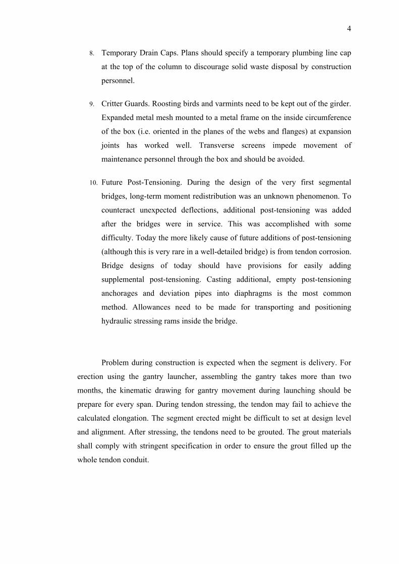
8. Temporary Drain Caps. Plans should specify a temporary plumbing line cap
at the top of the column to discourage solid waste disposal by construction
personnel.
9. Critter Guards. Roosting birds and varmints need to be kept out of the girder.
Expanded metal mesh mounted to a metal frame on the inside circumference
of the box (i.e. oriented in the planes of the webs and flanges) at expansion
joints has worked well. Transverse screens impede movement of
maintenance personnel through the box and should be avoided.
10. Future Post-Tensioning. During the design of the very first segmental
bridges, long-term moment redistribution was an unknown phenomenon. To
counteract unexpected deflections, additional post-tensioning was added
after the bridges were in service. This was accomplished with some
difficulty. Today the more likely cause of future additions of post-tensioning
(although this is very rare in a well-detailed bridge) is from tendon corrosion.
Bridge designs of today should have provisions for easily adding
supplemental post-tensioning. Casting additional, empty post-tensioning
anchorages and deviation pipes into diaphragms is the most common
method. Allowances need to be made for transporting and positioning
hydraulic stressing rams inside the bridge.
Problem during construction is expected when the segment is delivery. For
erection using the gantry launcher, assembling the gantry takes more than two
months, the kinematic drawing for gantry movement during launching should be
prepare for every span. During tendon stressing, the tendon may fail to achieve the
calculated elongation. The segment erected might be difficult to set at design level
and alignment. After stressing, the tendons need to be grouted. The grout materials
shall comply with stringent specification in order to ensure the grout filled up the
whole tendon conduit.

5
1.3 Objective
The aim of this master project is to study the system of the construction of
post tension precast box girder bridge using gantry launcher by Balance Cantilever
method.
The objectives of this master project are:
1. To determine the problems in manufacturing/fabricating the segmental box
girder at casting yard before deliver to site.
2. To determine the problem in precast segment erection/construction using the
overhead gantry launcher at site.
3. To propose the strategy for coordinated design procedure between consultant
and specialist contractor.
1.4 Scope and Limitation
This master project focused on the construction of bridge using precast
segmental box girder. The study is subjected to the following scopes and limitation:
1. This study is limited to the manufacturing of the segment by the short line
match-casting method.
2. The study is limited to the bridge construct using Post Tension Precasted
Segmental Box Girder erected using the gantry launcher by Balanced
Cantilever method.

6
Even though there are several method of construction of bridge for segmental
bridge, but the other method does not affected the modification of the segment and
structure.
1.5 Brief Research Methodology
The methodology used in conducting this research is through literature
search, structured interview with selected personnel that have direct involvement
with the manufacturing and erection of the segment and questionnaire survey among
the other person involved. The literature search explored the system used in
constructing the segmental bridge by Balance Cantilever Method as well as other
method available, advantages and disadvantages of the bridge construction method,
the history of it and the problem faced by the works that have been establish
somewhere else. Literature review is referred to the published journal, technical
paper and relevant book on the design, related and reliable website regarding the
construction, management and maintenance of the bridge.
The questionnaire survey has been conducted among the selected person
from the segment manufacturer and contractors in Malaysia to establish the problem
they faced in manufacturing the precast segment and erection of the segmental
bridge using the gantry launcher. A structured interview also has been conducted
with the segment manufacturer, contractors, consultant and the consultant’s
representative at site to seek their opinion and suggestion on how to improve the
construction procedures. The data compiled are analysed using simple frequency
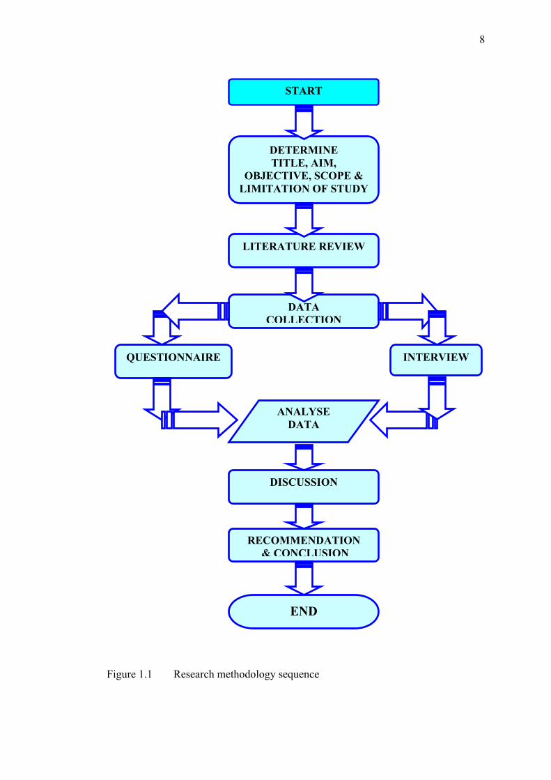
method and Relative Index Analysis. Figure 1.1 shows the research methodology
procedure and sequence in this study.
Based on the analysis and finding, several recommendation have been made
in according to the objective that have been set off earlier. The recommendation
represent constructive proposals and suggestions on how to eliminate or at least
7
minimise the problem that have been determine, thus could also eliminate the
problem that may occurs during operation and maintenance.
1.6 Limitation of the study
The limitation of the study is confined to construction of segmental box girder
bridge that being built in Malaysia by Balance Cantilever method only. Even though
there is several method of construction for segmental bridge such as span-by-span,
incremental launching, cast-in-situ segmental and normal cast-in-situ, but these
method do not involved modification carried out to the segmental box girder and
pier and no checking need to be done by contractor. The final construction drawing
has been incorporated all the designs and construction requirement by consultant.
8
Figure 1.1 Research methodology sequence
START
ANALYSE DATA
DISCUSSION
RECOMMENDATION& CONCLUSION
END
DETERMINE TITLE, AIM,
OBJECTIVE, SCOPE & LIMITATION OF STUDY
LITERATURE REVIEW
DATA COLLECTION
INTERVIEWQUESTIONNAIRE

129
REFERENCES
American Segmental Bridge Institute (2006). Grouting Recertification, American
Segmental Bridge Institute Magazine (SEGMENTS) Vol. 47, Winter.
Andrew C., Raymond S. (2006). “Method Statement for Segment Erection”, VSL
Engineers Sdn Bhd & Projalma Sdn Bhd JV (VPJV), Subang Kelana Link Project.
unpublished
Arthur M. P. (2004). “Precast Segmental Casting Yards: Past, Present And Future”,
PB Networks Online Magazine, Issue No. 57, Vol. XIX, Number 1. Feb. Website:
http://www.pbworld.com
Cliff F. ed. (2006). “Design and Construction of Segmental Concrete Bridges for
Service Life of 100 to 150 Years”, American Segmental Bridge Institute Magazine
(SEGMENTS) Vol. 47, Winter.
Federal Highway Administration (2003). “Task 15.2 Research Synthesis Statement:
Segmental Concrete Bridge Design and Construction Practices.” Washington D.C.,
Federal Highway Administration, U.S. Department of Transportation.
Website http://fhwa.dot.gov/BRIDGE/segmental/task15.2.htm
Federal Highway Administration (2003), “Segmental Concrete Bridge Technology –
Is a Segmental Bridge Right for You?” Federal Highway Administration, U.S.
Department of Transportation.
Website : http://fhwa.dot.gov/bridge/segmental/right.htm
130
Federal Highway Administration (2003), “Segmental Concrete Bridge Technology –
Is a Segmental Bridge Right for You?”, Federal Highway Administration, U.S.
Department of Transportation.
Website : http://fhwa.dot.gov/bridge/segmental/right.htm
Frank B., Scott W. D. (1997), “Fast Track Segmental Concrete Bridge”, PB
Networks Online Magazine, Issue No. 38, Vol. XI, Number 2. Spring,
Website: http://www.pbworld.com
Gunnar L., Jesus M.de la Garza. (2003). “Constructability Consideration for
Balanced Cantilever Construction”, Journal Practice Periodical on Structural
Design and Construction, Feb, pg 47-56.
Joseph K. T. (2004). “Considering Segmental Concrete Bridge”, PB Networks
Online Magazine, Feb, Issue No. 57, Vol. XIX, Number 1.
Website: http://www.pbworld.com
Juan A. M., Joseph I. S. (2004). “Brief History of Segmental Concrete Bridge
Construction”, PB Networks Online Magazine, Feb, Issue No. 57, Vol. XIX,
Number 1.
Website: http://www.pbworld.com
Juan A. M. (2004). “Advantages of Segmental Construction”, PB Networks Online
Magazine, Feb, Issue No. 57, Vol. XIX, Number 1.
Website: http://www.pbworld.com
Lee K. M., Raymond S. (2005) “Method Statement for Precast Segment
Manufacturing”, VSL Engineers Sdn Bhd & Projalma Sdn Bhd JV (VPJV), Subang
Kelana Link Project. unpublished.

131
LoBuono, J. (2005). “ Assembly required – The instruction for building New
Jersey’s first segmental bridge.” Chicago, Illinois: BridgesMagazineOnline.com
Sept/Oct.
Website : http://www.brisgebuildermagazine.com/
Low S. P., Choong J. C. (2001) “Just in Time Management of Precast Concrete
Components”, Journal of Construction Engineering and Management, Nov/Dec.
Maurice D. M. (2001). “Durability of Segmental Concrete Bridges” Journal of
Bridge Engineering, Vol. 6, No. 6, November/December, pg.539-542.
Poh B. S., Raymond S. (2006). ”Method Statement for Gantry Assembly”, VSL
Engineers Sdn Bhd & Projalma Sdn Bhd JV (VPJV), Subang Kelana Link Project,
April. unpublished.
Public Works Department of Malaysia (2004), Contract Document, Volume II,
Specification - Section 16, “Segmental Construction” for Projek Membina Jalan
Penyambung Subang Kelana, Public Works Department of Malaysia (PWD), Road
Division, Special Project Unit.
Raymond S., Lee K. M. (2005). “MS PowerPoint Presentation for segment
fabrication at Casting Yard, Batu Gajah, Perak”, VSL Engineers Sdn Bhd &
Projalma Sdn Bhd JV (VPJV) July . unpublished.
Raymond S., (2005). “MS PowerPoint Presentation for segment erection”. VSL
Engineers Sdn Bhd & Projalma Sdn Bhd JV (VPJV), July. unpublished.
Richard M. B., Mark L. H., Martha C. (2002), “50-year-old prestressed segmental
concrete bridge”, Journal of Professional Issues in Engineering Education and
Practice, April, pg 83-87

132
Poston R.W., Wouters J.P. (1998). “Durability of Precast Segmental Bridges” Final
Report for National Cooperative Highway Research Program, Transportation
Research Board, National Research Council, United State of America, June.
Wollman G. P., Breen J. E., Kreger M. E. (2000). “Anchorage of External Tendon in
End Diaphragms”, Journal of Bridge Engineering, August, pg 208-215
Vijay C., Peter A., Paul J. T. (2004), “South Bay Interchange: New Frontiers in
Segmental Construction”, PB Networks Online Magazine, Feb, Issue No. 57, Vol.
XIX, Number 1.
Website: http://www.pbworld.com
VSL Far East (2005) “Post tensioning Systems”, VSL Engineering Pte. Ltd., Hong Kong.