to lift and esclator industry association
TRANSCRIPT

To
LEIA
Lift and Esclator Industry Association
13 August 2021
Dear Sirs,
Re: Lifting Platforms – Vimec E10 EcoVimec
Maintenance Interventions - Technical note for maintenance engineers
In the constant effort to maintain the highest standards of its products, our company has decided to launch an
inspection campaign on its E10 (EcoVimec) model lifting platforms ("Platforms") for maintenance purposes. This
will allow the efficiency of the interested machines to be confirmed and maintained over time.
To continue to ensure the safety of the Platforms, the campaign will be developed in phases, punctually
organized and programmed. It will first concern the older Platforms built until 2014 and with a travel over 3
meters. In this sequence, the Platforms will be subjected to a number of checks on the state of certain
components, as well as minor preparatory work, to be carried out according to Vimec’s instructions. To allow the
timely execution of the inspection campaign, we are asking for this to be done as a matter of priority, and in any
case no later than the next 3 weeks.
We are taking the initiative and proactively writing to our dealers in the UK and asking them to undertake this
work or to forward these details to owners to arrange it with their current maintenance contractors.
We also consider valuable your help in this effort and, in the framework above, we request you to upload the
attached files named “Technical Note for Maintenance Engineers” (19 sheets) consisting of the following
documents, onto the Product Information area on the LEIA website. In this way, UK economic operators can be
further made aware of:
- “Vimec Techical Note August 2021”;
- The gearbox oil inspection instructions of July 2014;
- The report Of Inspection (Check List).
We trust that you will circulate this to all LEIA members, so that they are briefed to inspect the Platforms on their
portfolio accordingly. It is in fact possible that some of our dealers do not maintain the relevant units anymore
and third companies now do the work.
We thank you in advance for your assistance.
We remain at your disposal for any clarifications or information you may require.
Best regards,
Vimec S.r.l.

Technical bulletin No. 02/2021
Description of activities to carry out
1) Overspeed governor:
a) Put the unit in a safety working condition (maintenance mode)
b) Carry out ordinary checks on the device, of service manager’s pertinance, in particular on
pulleys paying attention to their wear.
Example: Proof of appropriate condition is the protrusion of the steel cable with respect
to pulley diameter (see picture1); on the other hand a wear index is the thickness of the
pulley side shoulders (see picture 2 and picture 3).
In case of wear the unit must be stopped and you will have to contact your After Sale Dept.
Manager to let you have the necessary replacement parts.
Considering that the pulley wear can have an impact on the correct working conditions of
the unit, while waiting for instructions by Vimec, stop the unit, as a precautionary
measure. As regards alluminium pulleys which are no more installed sicne 2013, please
refer also to Technical Bulletin No. 04/2013 about checks of material wear.
PHOTO 1

FOTO 2
FOTO 3
Further advice about pulley race wear, to be carried out by service engineer, and that we are
explaining in advance in relation to the new version of our new manual that we are going to issue
soon
Look carefully at the race surface in the contact area with the rope, it must be perfectly smooth without
any mark left by the rope

Check of race wear on traction pulley
In case you notice the rope track, replace the device.
To rub on the race surface the bit of a small screwdriver could be helpful:
• If the surface is regular or smooth the pulley can be considered Ok
• If the surface shows hollows or you can touch the ridging lefts by the wires of the rope
strands, the device must be replaced.
Rope marks: please check ridging left
by the wires of the rope strands.
Replace the part
Smooth surface without tracks
and/or marks : pulley OK

Check of race wear on traction pulley
If you see the rope track replace the device
c) The lower traction pulley is fixed by a grub screw (see photo 4), pull it out with a 2,5 mm
Allen key (see photo 5) and put in the new grub screw supplied to you. DO NOT USE any
grub screw different by the one supplied by Vimec.
PHOTO 4
Contact surface is polished and
without marks : pulley is Ok
Rope track on the race bottom:
replace the part

PHOTO 5
Should you find any difficulty in pulling the grub screw out or should you not be able do it
that means that it could be damaged. If so the unit must be stopped and you will have to
contact your Vimec Aftersale Dept. engineer for despatch and replacement of the
necessary parts. As it is known and taking into consideration wear of this part could have
an impact on the correct working condition of the unit, while waiting for instructions by
Vimec, stop the unit as a precautionary measure
After replacing the grub screw, use a permanent marker to draw carefully a visual check-
line (see photo 6) to be able to check eventual changing of position in the course of time:
PHOTO 6
d) Service engineer has to check overspeed governor steel rope integrity and that its path is
correct (see drawings below)

The rope must be :
1) Without any broken wire
2) Without any fold
3) Without oxidation
In case the rope condition does not satisfy one of the above-mentioned points replace the rope
The rope must be tightened as per instructions in our use and maintenance manual of the unit.
In case it is not stretched properly, tighten it as per our use and maintenance manual of the unit.
e) Check that the plastic shim under the spring of the overspeed governor, that was put to make
installation easier, has been removed (see Photo 7)

Photo 7
f) As per service engineer’s competence, check the correct installation of the whole
overspeed governor and of the safety gear as specified in the unit manual
g) As per service engineer’s competence, carry out the check of the overspeed governor and
safety gear activation as specified in the unit manual.
For all wear effects our After-Sales Dept will submit you an offer for the parts to be
replaced.
Wear checks as per service engineer’s competence, of safety gear
• Service engineer has to check the roller of safety gear: that has to show a
properly sharped and pointed knurling.
In case by touching it you find knurling has “flattened”, replace the couple of devices.

• As per service engineer’s competence check the safety gear setting; that must be
in compliance with what prescribed by the unit manual.
For all wear effects our After-Sales Dept will submit you an offer for the parts to be
replaced
2) Reduction gear motor oil
As per service engineer’s competence, check the oil level in the reduction gear and top it
up as per enclosed instructions (instructions about oil top up in reduction gear E10). We
are repeating these instructions as written in our Technical Bulletin No. 2/2014 and in our
manuals. Please see page 13 of this file and following
3) Check Brake’s Gap setting
a) Correct setting of the brake (minimum gap 0.30 mm; maximum gap 0.40 mm)
KO
OK
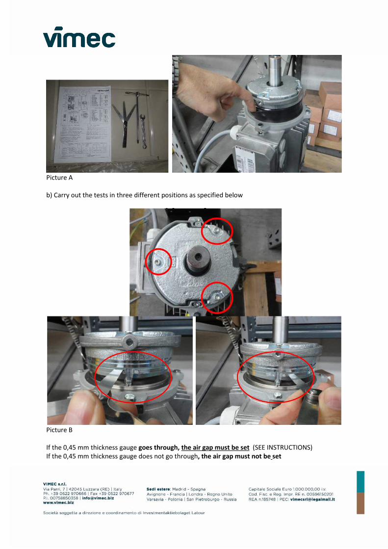
Picture A
b) Carry out the tests in three different positions as specified below
Picture B
If the 0,45 mm thickness gauge goes through, the air gap must be set (SEE INSTRUCTIONS)
If the 0,45 mm thickness gauge does not go through, the air gap must not be set

Air gap setting
CHECK, AS PER SERVICE ENGINEER’S COMPENTENCE, SAFETY GEAR ACTIVATION
Before carrying out the overspeed governor and safety gear check you have to verify that all screws of
overspeed and safety gear system are properly tightened.
The test of the system must be carried out with no load (empty cabin).
After activation of mechanical safety gear, safety gear roller tracks must be smooth to the touch and
must look like the ones in the picture below. There must be NO hollow on the rail, there must be NO
sliding mark (slipping).
Roller trace on the rail must be well shaped and short.
Marks must be visible in the same way on both rails.
OVERSPEED GOVERNOR AND PFB SAFETY GEAR – Stop between 150 and 300 mm
DYNATECH OVERSPEED GOVERNOR AND SAFETY GEAR – Stop between 300 and 600 mm
(in case you find different ranges please set activation mechanism of the safety gear as per our
manual. For other cases please contact Vimec After Sales Dept. Manager of your area )
Hereunder see two pictures as an example
- Unloose nut 2 keeping screw 1 fixed
- Set the air gap by intervening on screw 1,
0,3 mm and 0,4 mm air gap GOES
THROUGH (we remind you that 0,45 mm
thickness gauge DOES NOT GO THROUGH
(maximum allowed gap)
- At the end of setting, tighten nuts 2 by
keeping screw 1 fixed
- Setting must be carried out UNIFORMLY
on all 3 screws

Correct mark, well shaped and short
INCORRECT mark, knurling not well marked and with hollow on the rail.
In this case go on with safety gear setting and/or replacement.
Conclusions
Important: write down all checks you carried out as per our above-mentioned instructions on your
working report and specify also the unit working hours. Working report will have to be countersigned
by the customer, if possible.

Write down on your working report the engineer’s working hours (tests described can be carried out
by a single engineer and the average working time we foresee is 2 hours. For additional charges please
ask your After Sales Dept. Manager for authorization in advance.
Send your working report per e-mail to the address [email protected]
After approval send invoice of your working hours on site, the invoice MUST compulsorily mention
part No. UPGE10 + unit order and serial No.
We kindly ask you to carry them out with the outmost celerity
VIMEC Srl
Claudio Savazzi
Export Business Unit
Aftersales Service Manager
Parts required for your site visit:
• 2,5mm Allen key
• Thickness gauge
• Permanent marker
• Syringe 150 cc as you can find on the market
• Grub screw exclusively supplied by VIMEC (for no reason you have to buy this grub screw on
the market)
• Oil for reduction gear that you can find on the market type :
1) SHELL TIVELA S320
2) SHELL TIVELA SC 320
3) ARAL DEGOL GS 320
4) IP TELIUM OIL VSF 320 (AGIP)
5) TOTAL CARTER SY 320
6) MOBIL GLYGOYLE HE 320

ISPEZIONE OLIO RIDUTTORE / GEAR BOX OIL INSPECTION
Istruzioni dal Bollettino Tecnico 2/2014 - Instructions from Technical Bullettin No. 2/2014
Istruzioni rabbocco olio su motoriduttore E10 Gearbox E10 : Oil filling instruction (03/07/2014)
1)
2)
Sollevare la cabina e mettere in sicurezza
l’impianto
Lift the cabin and secure the machine
Togliere il tappo indicato (1)
Remove the oil filler cap (1)
3)
4)
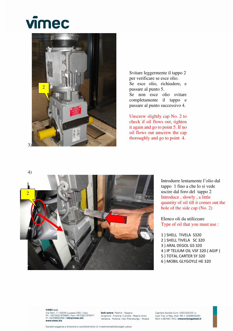
Introdurre lentamente l’olio dal
tappo 1 fino a che lo si vede
uscire dal foro del tappo 2
Introduce , slowly , a little
quantity of oil till it comes out the
hole of the side cap (No. 2)
Elenco oli da utilizzare
Type of oil that you must use :
1 ) SHELL TIVELA S320
2 ) SHELL TIVELA SC 320
3 ) ARAL DEGOL GS 320
4 ) IP TELIUM OIL VSF 320 ( AGIP )
5 ) TOTAL CARTER SY 320
6 ) MOBIL GLYGOYLE HE 320
Svitare leggermente il tappo 2
per verificare se esce olio.
Se esce olio, richiudere, e
passare al punto 5.
Se non esce olio svitare
completamente il tappo e
passare al punto successivo 4.
Unscrew slightly cap No. 2 to
check if oil flows out, tighten
it again and go to point 5. If no
oil flows out unscrew the cap
thoroughly and go to point 4.
2
2

5)
6)
Dopo che si è visto uscire l’olio
dal tappo n.2 rimontare e serrare
il tappo.
After seeing oil flowing out from
cap No. 2 put the cap in again and
tighten it.
2
Dopo aver richiuso il tappo n.2
aggiungere 150 cc di olio
ulteriori dal tappo n.1.
After tightening cap No. 2
pour 150 cc oil additionally
through cap No. 1.

7)
8)
Rimontare e serrare il tappo.
Close filler cap
Specula di verifica livello
Oil visual check
Punto di rabbocco olio
Filler Cap
1) SHELL TIVE Tipi d’olio utilizzabili / Oil types to be used
2) SHELL TIVELA SC 320
3) ARAL DEGOL GS 320
4) IP TELIUM OIL VSF 320 (AGIP)
5) TOTAL CARTER SY 320
6) MOBIL GLYGOYLE HE 320
Motoriduttore fornito dal 2014
Gear Box supplied from 2014

9)
Se il livello dell’olio è inferiore alla metà della specula : aggiungere olio dal
punto di rabbocco fino a che il livello non supera la metà della specula
If the oil level is less than half of the sight glass: add oil from the top-up
point until the level exceeds half of the sight glass.
Se il livello dell’olio è superiore alla metà della specula : OK
If the oil level is higher than half of the sight glass : OK

Pag. 1 / 2 CHECK LIST – OSG E10 Rev. 03 02/08/2021
INSPECTION & VERIFICATION FORM
OVER SPEED GOVERNOR - CHECK LIST (CFR. Checks indicated in Technical Bulletin No. 2 / 2021)
MODEL E10
SERIAL NUMBER : ____________ WORKING TIME ____________ We remind you that the operating hours are written in the CPU in the TIME - WORKING TIME menu.
SERVICE CENTER:
AUTORIZZATO VIMEC / AUTHORIZED VIMEC
DISTRIBUTORE / DEALER
DITTA ASCENSORISTA / PASSENGER LIFT COMPANY
ALTRO / OTHER
!! Please carry out these activities as quickly as possible!
LIST OF OPERATION CARRIED OUT: 1) Check over speed governor’s pulley
• · Visual inspection of the pulley grooves - YES, pulleys are free of wear…………………………
NO, pulleys have wear:
• Over speed governor replaced……………………………………………………………………………………..
• Blocked the use of the lifting platform waiting for a comparison with VIMEC……………..
2) Pulley’s screw replacement
• Replacement of the grub screw of the Over Speer Governor …………………………………….
• I could NOT extract the grub screw of the Over Speed Governor:
• Over Speed governor replaced…………………………………………………………………………………….
• Blocked the use of the lifting platform waiting for a comparison with VIMEC……………..
• After replacing the grub screw I proceed by running visual line of faith between pulley
and shaft …………………………………………………………………………………………………………………….
• Performed Over Speed Governor test with POSITIVE result (PFB 150/300mm - Dynatech
300/600mm) Braking distance ________mm…………………………………………………………………….
• Mechanical Safety Gear activation verified with POSITIVE outcome…………………………….
• Left the unit working with Over Speed Governor 3714120 ………………………………………….
3) Check the condition and the tensioning of the OSG‘s rope
• The rope is in good condition……………………………………………………………………………………….
• The rope was NOT in good condition and I replaced it …………………………………………………
• Correct rope tensioning ………………………………………………………………………………………………..
• The tensioning of the rope was NOT correct and I adjusted it...........................................
4 ) Check the correct presence of OIL in the gearbox, which is free of abnormal noises
• The oil level in the gearbox is normal and the gearbox does not make any unusual
abnormal noises ………………………………………………………………………………………………………………..
• The oil level in the gearbox is NOT normal and the gearbox does make unusual and
abnormal noises Topping ________ml ……………………………………………………………………………….
• Blocked the use of the elevator platform pending a discussion with Vimec…..………………

Pag. 1 / 2 CHECK LIST – OSG E10 Rev. 03 02/08/2021
5) Check the correct adjustment of the motor brake
• Air gap is between 0.3 mm and 0.4 m………………………………………………………………………….
• The air gap distance was NOT between 0.3 mm and 0.4 mm and I adjusted it…………….
6) All checks were carried out in accordance with Technical Bulletin No. 2/2021………..
ATTENTION!
As a maintenance engineer, I stopped the lifting platform for the following reason:
………………………………………………………………………………………………
………………………………………………………………………………………………
COMPANY: ___________________________________________
Name and Surname of the maintenance engineer ;
_________________________________________
Date : __/__ / ______