to - dtice volumetric efficiency “pi inlet-air densit~ (3). b-—-. g air consumption per unit...
TRANSCRIPT

UNCLASSIFIED
AD NUMBER
CLASSIFICATION CHANGESTO:FROM:
LIMITATION CHANGESTO:
FROM:
AUTHORITY
THIS PAGE IS UNCLASSIFIED
ADB805787
unclassified
restricted
Approved for public release; distribution isunlimited.
Distribution authorized to DoD only;Administrative/Operational Use; DEC 1940. Otherrequests shall be referred to NationalAeronautics and Space Administration,Washington, DC. Pre-dates formal DoDdistribution statements. Treat as DoD only.
NACA list dtd 28 Sep 1945; NASA TR Serverwebsite

3iis&?i=7.&m~~Am“--kpmmshtheuu” ?wadnwiaJSemk+9
&*mtiuu w ofAxw4sifwmuqtbeinfmnd
!l?ECHYICAL NOTES
%NATIONAL AI)VISORY COMMITTEE FOR 4ERONAUTZ CS
.. . ..r“.
-.
\“”.
—,..—- _
\.’,. . —.-j,,-_.-=-- ------ “ ._=.
i- —--—- - . .-_A - =..—.—=.==
.; . -{-~= . ~; :. .“, .’. :----.bV-- f.. --”---—-.“---- j/’..yr ,GAlt ... ?+-’-- .++::;;?;$-4$2......‘“--’-”””+-k,;~””~;,$&:.1 -$( :~$--,.‘ ..’ - ._”+#’2..:;:=;“=---’7;;
..-....-~.~.. . , . .. c~-~. . .. -. .-. . . .:,.=---- ... .—-”-,.._ ...--- ............ .- ,.-4. .
- ——-— . -------
-:. r.... ,..
No . 787-—— -—
.-
FACZ!ORS AI’FECTING 3H3AT TQWSFER IN --—
TEE INgERNAL-COHBUST IOti ENGINE.-—
I!y P. M. KuMassachusetts Institute of ~ec-h-~Lolo&””-
.—.._-
.-
--- f~ .,-.“:-. . ....4,.< J
. . . ● . .,
I ~fl r -- ““ ;--”:._._ .“:f::s~.=.=-—--c
.J ;\,,d LZ::=15Y . . .. ....
,., ..— --- .,-.:....:+“ ----- ..—1 ! F..:,m2utical
...A ..-:{;j~:,;!m,.. *. .... ..=_”~.--.-..... .._:........
~~lx)rdoryi. .: ,-....r.=+::.-...: ....,-.-::=..=
4 :? .-....-
W2shington .-Deconbor 1940 :----...-.—.-
..
.
Illlllilllll[lllllllllllllllllllllllll~“”-‘“31176014337589
— —1
.- —... -
..— ______
NAT IGNAL AD~~SORY COMMITTI!HI FOR AERONAUTICS.“ .,-———
~~C=?ICAL NOTE NO.,.78?,, -... ....-— ;,.~J
.—
,,
— .
FACTORS AIWICTING HZAT Z“fikSF.@t IN-.
..!....-
-..“. ,... :
T5EINT~~{AL-COb[BUSTI:Ofi::SNGIN~ .-..,.,. 1+,,,.
By P-* M.- Eti :.....,,, —. . ... ,.. .. . .
,. ”., “s.uMMARy -: ‘.....,,, . --.-—,,, ,. >:..
,., ,.,. .
A method &sde~eioped for. ti6”:~~i2ec~ ~e~sur~fiew.o~-- ‘.~”-’the average hea%-~ransfer caef;iciqt.fr~n the ~a~es i.nthe cylinder during the,,cycle o: operation of an.inte.:-QRl-conhustion engine., .Experimenfa, l.me&$urenents were nadewith a heat collector pyojec%izk t~$qti%h a sP~-r~-Plu~...hoe.e.into the conbus%ion.cdmm%er of the’~%~at e~~ine, tri orderto oxanine the. effects .of several 6QS’ine-operatin% ant
..—-—
desiqn parameters ,OT.the nean he”at..}~an.sfor to the collec-tor.
,, Y-_--L-_+_..-_. .,-_ -.’, .1...
The effect, of “the he~t-res$stive coaf~nq; formed ‘Bythe combustion. deposits on the surface of” t%e’”heat col-lector was also ex.ami.ned. Start3nq with, a Cletiti“~~at–c~- – 1lector, the heat transfer feii’ about 201percont during thefirst 15 hours .of operation, a.f~9r.w~ich it fell off at avery slow rate, becominq constant after about 40 hours of ““ ._operation. ,.’---;? :..,,..,” ,.-..., .—T
,., .,.. . ...,,+,. ....lNTRC):DU@~0.~..; —— .=— —
, “..,.;.,.,-..,... . ... . . . ., ——There are several mpthodS’ffo.r e“~?~u~tin~ heat 10s SGS .;
in the internal -combust-ion enqine. Those methods ray ho‘oroadly divided into two categories: one based upon the ., —
—

2 NACA Technical Note. No. 787
-..i
..-. .2’
.,\
thermodynamic analysis of indicator diagrams (references1 and 2), and the other %ased upon the measurement of thetotal amount of heat absorbed by water jackets (references ‘-3, 4, and 5) or cooling air (reference 6). The changesthat actually occur in the engine cylinder are so complic-ated in nature that no nethod of theoretical analysis orexperimental investlqation may claim to have yielded en-tirely satisfactory rOsults.
. .
Investigators of the first category often contend 1that the direct neasurene~t. of heat absorbed by jacketwater or cooling air has no actual bearing on the ther~o-dynanics of the engine, as an unknown proportion of ex- I
haust heat absorbed %y the exhqust port and,its surround-ings, as well as the uncertain anount of piston-frictionheat , inevitably creep into the meastirenent. This argu-ment is quite correc’t. Hotiever, the analysis based uponthe indicator diaqran doesnoi appetir to give resultswhich finally justify the a~ount ‘of“labor called for, andit doQs not give a“qood picture of the mechanisn of heattransfer and factors controll~ng sane, SO that thq Prac-tical application of such analysis is rather linited. Itwould be of ~reat thernodynanic interest if sufficiently-reliable indicator diaqrgns were obtainable at high speeds,so that instantaneous gas tenpera~ures could be conputed t
fron these diaqrtins without’ serious error.
The present investigation is an attempt to evaluate%
the effec%s of air consumption mean piston speed, mix-ture ratio, and comp~ession ratio on the mean heat trans-fer from the hot qasesto a heat collector screwed intothe combustion chamber of the ’.sp”ark-ignition engine. Heatexchanqe between the cyliilder walls and the heat collectorwas reduced to the possible minimun %y the provision of adead-air space around the heat collector, and by equaliz-ing; the temperatures of the t’wo bQdies. The interestingfeatures of this arrangement are:
(1) Heat transfer from the exhau$t’ system was absent.,.
(2) Heat transfer “under conditions of sonic velocitydurin~ the exhaust l~blow-down” period was al-most completely a.b,sent.. .
(3) Effect of piston-friction heat was almost com-pletely exclu-ded- .

N$CA T echn~o.al .IfQt e .lTb..787 3
In other wordq, the heat transfer determined IJY thismethod corresponded to the 10SS durinq the thermodynamiccycle of operation. Alsoi the Labor and inaccuracy of theindicator-diaqram method was saved. —
The author desires to take this opportunity to ex- ‘-pr~ss his thanks to Pr~fessors. C. F. Taylor and 1. S.Taylor, of the Massachusetts Itistithte” of Technolo~~, forthe adv%ce and helj? they have rendered.
..,.He iS ‘al”s.oin- ““--”—–—–
debted to Professor A. R. Roqowski, Mr. W. A. Leary, andMr. C. H. Wanq for,thetr assistance at. various times.
GENERAL EQUATION OF HEAT! TRANSFER —
In the evaluation of the heat transfer from the hotcylinder gases to the c~linder, it is necessary to consid-er the relative proportions of heat transmitted %y- radia-tion and convection. An accurate estimation of radiationis extremely dif”figult .(r8fere~ce~7, 8, 9, 10, 11, and12); knit from’ what is known it ap’pears certain that theheat transfer due to radiation is very snail. In the nodrn”-ern hiq%-speed inteynal-ctitiau~ti.on epqine , in which heattransfer takes place Mainly ‘oy forced convection; rZidi.a-tion nay be taken as negligible.
For the heat traq?fer 37 neans of forced convection,it ray be shown (refe~enc”e 13) t&j,t, for a qiven engine
where
‘1... “:.,, .
Q= KI. (&- Tw) L2 (p sin~~-’I . ,. . . . ;.
,-
(1)——
Q
P
IJ
L..”
s...
nean heat transfer per unit tine
affecti+o %as temperature,,
avaraqe d~’linder-wall temperature
effective qas densZty, .-,. ,:effective gas viscosity (absolute:)
a characteristic lenqth of the engine
n’ean piston speed {2 S N) : ~’ , . ,<.
..
. . .,

●
4 NACA Technical Note No. 787 ,
s str.oko
N engimo speed -.. .-—+=
K Ii n constants .
.-
Neg~ecting the vari~tirjn ill ~, “which is probably smallfor ordinary operating conditions, equation (1) nay bewritten
.
,.. *
Q= Ka l~+n (p S)n (Tg - Tm) . (2)
But
Eence
t
P =K3 (e pi)—=
Q= K4 (e Pi S)n Ll+n (T - Tw)g
all=Kq (e Pi s L ) L‘-n (Tg - Tw)
= K5 Gn L2-m (Tg - l?w)
where
*e volumetric efficiency
“Pi inlet-air densit~
(3)
.
b-—-
.
G air consumption per unit tine
Ka, X3, Ka, K5 constants
It is of interest to not~ that tho heat tro,nsfor fromthe hot qases to the cylinder is a function of air consump-tion, no na,tter what chnnqes the volumetric efficiency,inlet-air d~nsity, or LIearipiston spocd nay under%o.
Equation (3) may he wri.tton in .anoro gone”ralized fern—
to includo sone .03 the inportant dosiqn and operatinq parnn- --eters: *
.-——.—-—____— .—
—- ——*Tolunetric efficiency is herein defined as the ratio of tho *
weiqht of air actually taken into the cylinder to tho weightof air which would fill the piston displacement at t-ho inletdensity.

., ,.
..
NACA !lechnical. Note NO. 7EIT,’ 5
. . . .- r.. __
f indicates an nnknown function ..,,.
r compression ratio
a Yalve timing ..8. . . -.—-, . ,“-
~ fuel-air ratio......
A. . . ..,.
6 ignition advance . . . , ..... __
In equation (4) the, g’ff.betof ~he quantity e is to a“lt;rthe instantaneous ~alues. of ~a~ temperature, gas. pressure,gas density a~d viscosity, etc., all of .wh.i.cha.ro fw_c-tions of the ‘indicn.”tordiagran. It will be noted wtthreference to fiqure 1 that for &ifSerent engine-operat-ing conditions the indicator dtagrans are very similar instroke if the ignit-icin advan”ce iS set to give. ~ressurepeaks o,% the ‘Same crank-e.n~le position. !I!h-asthe iqni--,,ttou ad+ahce “~”$pinq the pressure ~eak .at~,t.he.san.ecrank-
——
anqle posi”tibn would appear’to be the. r“ati”o~al&a@is of........conpartsonc’
..__. ...”--. .., ,“,.. -.—.-.” ,,.-
In “other ~ords, E2qUS,tiO~ (3) Ys valid f.&? geometri-cally sinilar’ eriginbs of the same” dcj;mpressio~ rat~o andvalve timinq, operating with the sane “mixt~ure..ratio, withignition adjusted to give naxinun ~ressure at tho sanecrank~anqle position.
,-—.
. .,. ,, ,-
“APPARA?XJS AND EXPERIMENTAL NOTES -. . ..,. . .
. . ..,,, !..-
‘This investigatioti covers tests,.on a slow-speed anda high-speed C.F.R. en.qine, of maximum perrn:ssible. speedsof 1800 and 3600 rpm, respectively. In the slow-speedC.F.R. enqine a constant mixtutie r~tio c~”ul!”dnot 39 verywell naintair,&& in’ a 3-minute runt .an account of the un~ —
satisfactory fuel-supply system. In the hiqh-speed C.F.R.enqine, a rather elaborate scheme was enployed, in whichthe fuel was injected into a vaporizing tank by neans of apump operatinq at 25 pounds per square i~ch supply pres-
,—

6 NACA Technical Note No. 7+37
sure. The injection nozzle IVO,S rade to deliver fuel at apressure of 1200 pounds per square inch., the spray anglebeing 12° and the atomization good. The fuel was thenmixed with air in the vaporizing tank, which was stoam-jackoted to insure %ood vaporization. With this arranqo-nent it was possible to obtain an alnost perfectly hono-qenqous nixture to he taken into- tho cylinder. Reference14 contains a noro complete description of tha inlet sys-tcln. The nixture ronai.nad constant for practically anylength of tino by kcepin~ the ftiel=supply pressuro as wellas the nixture temperature constant. Fi%ure 2 shows tho
f
hiqh-spood C.T.R* enqine set-up, and figure 3 shows theview of tho heat collector in position.
Heat collector.-= Apart from the complication intro- ...—.— .——__duced hy the exhaust heat and the pistm=-friction heat,difficulty WnS experienced by prev$.ous investigators withdirect mea~urement of heat ~iven Up to the jacket water.Considerable difficulty was found in keepi~g the enqine-jacket temperature constant. When the rate of flotv of wa- .ter was made large enough to give a steady temperature rise,the temperature rise was too small for a reasonabi:~ accu-rate estimation of heat transfer. If-, on the other hand,the rate of ;Vater circul~,tion 17as made sufficiently small, .~team Ilpockets’1 ‘were formed in the jacket which disturbed bthe temperature readings. —.
This difficulty was overcome by the use of a heat col- *I.ector shO\Tn sectionally in figure ~. A quite similar ar-rangement had been employed 14 years ago for heat measure-ment during motoring tests (reference 3); but for reasonsobscure to the present author the work was not carriedfurther to power runs; In it’s present version the heatcollector consists mainly of, two concentric steel tubes,put together,by a suita~le, supporting element. Jointswere made watertight by press fitting. NO brazing or weld-”inq was used. ‘
The heat collectbr was then sc~eved into the combus-tion chamber of the enqine under test t’hrouqh a spark-plug hole. Cold water was made to enter the inner tul)e,while hot water ran out fromheat transfer was determined.circulating ~7ater as well astemperatures.
The area of th; portion
the outer tube. The rate ofby measuring t-ho weiqht ofthe inlet and outlet water t
,.
of heat collector. exposed to .
the hot gases was 3C’75 squ~re inches and its VOIU~Q, 0.44
,.

NACA Technical Note No* “7.87 7
cubic inch. OwiEq to the volume taken up%y tho heat col-lector tho compression ratio of the enqine was altered.A calibration curve for the various compression rattoscovered ‘Dy tho experiment is ~ivon in fi~ure 5.
In order to qwrd. a~ainst heat oxchnnqe %et-meen theheat collector and the cylinder walls, a dead-air sp-acewas provided in the suyportinq part of the tieai collec-tor. Clearly, a complete absence of metaliic con~a~snot possi%le, and the air in the dead-air space was notreally lfdeadl*in the sense that sm.all-sc&lG”Wrlmlence al-ways existed, hence reducinq the effective heat insulationof t-he air space. As a necessary precaution the tempera-tures of the water jacket arid the heat-collector outletwere adjusted to the same value throughout the experiment,except in the first 40 hours of preliminary runs, in or-der to elininate heat transfer fron the supporting portof the collector.
It ?vas renarked that when steam pockets were formed,the temperature readings became very unsteatiy, because theformation of steam bubblss caused the heat-transfer char-.acteristics to change considerably. In the present vorkwater was. kept circulating% .wi’thout stagnation points, and
● the outlet “temperature of. the heat callector was kept be--1OW 150°.F. There .-was.no evidence of stean fornaiion= Asufficiently large temparatui-e rise was obtainable, yet
““ the temperature fluctuation wasF
only of the order of ~0.5°in a 3-minute run, correspotidia~ roughly to a half-
percent error; Even whenthe hea’t~collector outlet ten-perature was ‘raised.to 180?, F, no qreater ten~eratur-efluctuation was observed. ,
Temperature ootitral,= TheschemO for the control of——__ ______temperature iS shol~n in figure 6. . ,The effective head ofwater in the supplj tank was maintained constant, and therate of flow was adjusted @y a needle valve. An extremelyfine control of temperat~,re was o%.tai,nable. The engine-jacket waterwas circul~te~ by rn&”ns o.f.a ce~tiifugal pump,cold water ‘beinq adrnitted,~:or t,emporat.ure adjustment.With this arrangement, the onqine-jacket’ temperature” couldhe maintained at ~3° F from the heat-collector outlet tem-perature in “a 3-minutO run.
:,
In a work’ of this kindi it is imperative. that a p.q.r-fect tenperat,ure, equilibrium %e reached .p,rhlorto_rtakinqformal readi~gs. From 1.t.o l+ hours would. qenernlly”%erequired for ‘an enqine starting fron cold. About 15 rzin-
—-
..
.
.
.

... .,.... . .8 NACA Technical NotQ No. ’78? .
utes were allowed when eng~ne- -condition’s”had “%een a“ltered -The oil temperature was ,noti specially controlled Put wasalways around 140° Y. ; I
Air measurement.- In this work an NACA R.O~*s-*YPe—— —-——-supercharger”was used as an air neter. Calibration aqainsta “Durleyorifice. showed that one revolution of.the metercorresponded to “0.180 culi.c foot of air. Surqinq in theintake s~stem was suppressed.by a sur%e tank of suffic}eqtcapacity. *
Fuel-air-ratio ~easurement.- The mixture ratio was.—-——— ————-——nornally taken Yron a Gambridge ExhauSt.-Gas Analyzer. In
. ..4
tests in which mixture ratio was ipportant-i--the fu’el mndair wore tin’”edand tho mixture ratio 17as conputed.
.
On the high-spaed C.F.R. enqine set-up, .an elect-ricaldevice was provided for taking the fu~’1 cind air readingssimultaneously.
. .
The Canbridqe” analyzer was found to <ive re~ding”s”sufficiently .accurate for most purposes.,.
~~eed”measuremen t.-The enqine speed 17as“read by a—. —.hand tachometer in tests. on the slow-speed C.T.Ri enqine.A Strobotac “operating from,a controlled 60-EYcle line;
“was used OE the hi~h-speed C.F.P.. enqine (reference 14)0
Procedure.- The major factors, the effect ofiwhich.-—— ———were to be examined, were: “volumetric efficiency, inlet-air density, and mean piston speed. Trtals. were accord-ingly made with
(1)
(2)
(3)
(4)
Constant s and varying (e 15i”); “by throttling
the engine while the engine speed was heldconstant.
Constant Pi and Var$itiq (e s) : by keepin%th,e same inlet-air density while the enginespeed was varied.
Constant (e Pi) and varying s: ‘by throttling
.the engine in suc,h a way that the air consump-tion per stroke waq t’ke same.
Varyin< s, e, and pt: by varying engine speedand enqine throttle at random-
.
,
.
—

——
NACA Elechhical Note’ No. 787 “9
The effect of volu~e%ric efficiency al.ono was notseparately’ examined, owing to the fact that it could notbe varied over a sufficiently wide ranqe without havingaffected the in~et-~ir density at the samo timO.
The ignition advance was adjusted to %~~e best Po~~rin all runs except those wherq it was intentionally vari-ed. The best-power-ignition advance was found to giveconsistently a pressure peak at from 12° to 15° after topdead center. Tests thus made were therefore on a rationalbasis of comparison.
The effects of. mixture ratio, i%nition advance, andcompression ratio were also examined from a dimensionalstandpoint. “
..
It is seen from equation (4) that;in order to ‘evalu-ate the effect of one yarameter’alone ,-it is necessary u-o
=.--—
keep all the other parameters constant. For example, in,order to examine the effect of the mean piston speed .orenqine speed, it is not sufficient to kaep the inlet-airdensity constant; Accaunt must also be taken of the vari-ation of volumetric efficiency. In”order to exarn~ne-=o -effect of mixture ratio, ignition advanc~, or compressionratto , it is not sufficient to keep the “moan piston sP~edconstant ; the air cbnsum~tion”must be kept constant so asto make the comparison dimensionally correct. It has ap=peared to the writer that some authorities have f“a31-6Ttotake notice .of this point. ‘ ‘ - .— .--—-=.-—-.
,. .-.
RESULTS AND DZSCIJSSIONS ~
----
—
—.—
,,, -, . ., .“ . -,:,
This report outl’ines the conditions of heat transfer __corresponding to the thermodynamic cycle of operation ina particular region” in-theengine cylfnder. The condi-tions of.heat transfer in 5nother reqian will’ necessarilyassume a different naqnj.tude but will, it is %elieVed,follow a similar trend. :.“
-. ,.,
It wilL also he seen immediately that there was a re-markable aqreement betrvoen tests on the slow-speed andthe hiqh-speed C.F.R. engine. This fact may be attributedto the similarity in engine desi%n. Whether it will be soin enqines of entirely.iiifferent desiqns cannot be stated~ithout experitiental verification. Nevertheless, as ?heproblem is related to the thermodynamic CYC1O only, it aP-poars reasonable to expect a materially similar trend.

10
*
Heat transfer hv radiation - The, heat collector was———— —..--=— .completely chromium-plated in order to determine if radia-tion from the hot gases could be measured. It was at firstthought that if the heat transfer became qreater as sootand lead oxides were deyosited oh the polished tube sur-face, the difference in heat transfer could “he attributed
—.
to r,~.diation. Subsequently no such indication was observed.It maybe concluded that radiation heat transfer was atleast smaller than the experimental error. .,
.Effect of heat-re~istive coati~.- In libu of the——— —— —a_
trend as suspected, the mean heat transi’or was found to de-cline very decidedly as a result of those coatin?s. This ,
tendency is shown in figure 7, in which the heat f~ow perunit time is plottod against hours Of operation for t’h~
same amount of air flow. This tmdency was f-und to have ‘ ‘“practically ceased after 40 hours OF opora~ion. !lhe coat-ing was 0.002 inch in thickness .aftar “about 80 hours ofoperation.
E&fect of. mixture ratiot- Tbe effect of mixtur~ ratio— —- —-——on the mean heat transfer is shown in fi%ures 8 and 9-This effect is plainly due to tbo chan%o in qas tempera-ture, for in.equation (4), r, a, and 0 do not enter’ be-cause these parameters were kept un~.er dimensionally cor-
rect _ba6is, G was a constant by adjustment, and L forthe heat collector, was also a constant.
The maxi.mun >eat transfer was found to occur with afuel-air ratio of 0.074, or with amixturo approximately 7
/
percent richer than cbomical~Y correct, which correspondsto—the mixture ratio qivinq maxlzn.zm qas temperature .
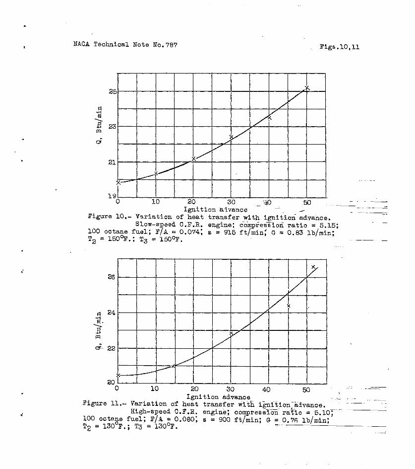
~g~gct ofdsnftioc advance.- Z:T n similar argument the———-offect of ignition advance may also ha attri”outod to thechanqe of gas temperature. The r:elation between the noanheat transfer and ignition advance is shown in figures 10and 12, for the slow-speed and tho hiqb-speed C.F.-R. en-gines, respectively. The oxperinont coverod a range of i7-nition ad~ance fron 0° to 50° crank angle. It ras-not pos-sible to admmce the ignition to more than 50°, as preigni-tion sot in aqd t-he enqino ran very irrequla.rly. At 50nignition advance the enqino ~f~~e~. fire onc~ in about 12power strokes. r-
. . .
~~~ect o= compressing ratio.-.— —.. I’t’2.ures12 and 13 showthat a sli~ht ~ncrea8e in nean heat transfer accompanied *
an incronso in coqrcssion ratio. An increase in conpres-
ston ratio is known td raise tio conprcssion tonpera.tureand tho f-lane temperature slightlmy and to lower the oxp~n-sion temperature and the exhaust tenpera~ure to a _qreat”erextent . Eence the total effective heat transfer fro~ t~oengino and its exhaust system is ordinarily found to de-creaso with an increase in conpre~sion ratio. In this i.n-vest5gatioc, ~-~~~~~r,. the heat transfer f~oa the ‘cx~austSyston. was laZ301y absent. Therefore, it is logical thattho nean heat transfer ~as feud to increase slightly withan increase in compression ratio.
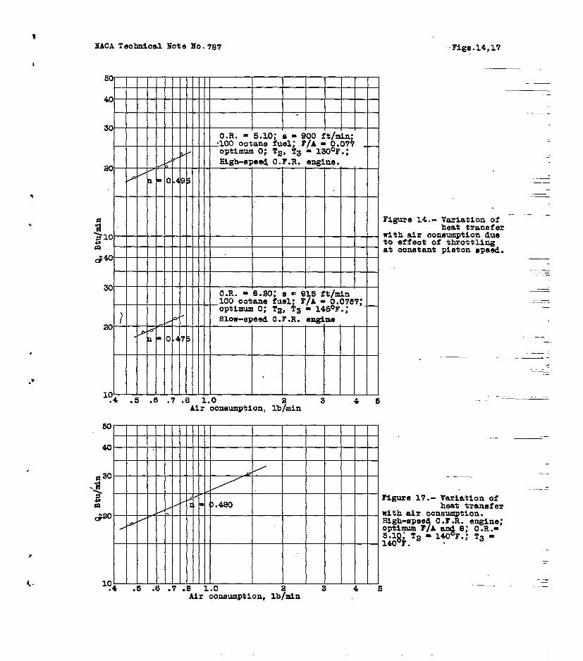
Effect OF t?lrottling.- ~~e effect of thrott~j,ng, as—=.——— +.————_—shown in figure 14, can he readily explained ‘oy‘e”~uation(~). Throttling decreases the flane temperature and.thoexpansion temperature slightly and increases the conpyos-9i0n tengor”~turo to a greater extent. The net efftict of
.
-.
..
—
- -.
throttli~g on the tern- (Tr - Tw), is probably sm”all.The 7ariation of the mean ~eat iransfer vith throt.t;ihgna,y be mainly ascribed tc the effect of change in density,which in turn affects the air” consumption. The exponantn, was found to. be very .r.early 0.5.
zxZE@_QZ_J2Q.aG_l.Z&.QQ_&!ud ● - Fron equation (3) i.k.is clear that the effeet of nean piston speed on the ne~nheat transfer is the same as that of air consumption wic3nthe volunetrzc efficio~.cy and inlet-air ‘density are kept
constant . !7!h,eexponent n. was ELso vary nc3arly 0.5. (Sef3fiq. 15.)
Effect of air consur.rtioP.O- Figures 16 and 17 shol~————_— ________ ____the roiation bot~~cen the mean heat transfer and the airconsumption when the volumetric efficiency, mean pistonspeed, and Inlet-air density ‘are varied ~tt.random, aswell as the compression rat~p. Some results from thefirst 40 hours of preliminary runs are also included toslhow that, mhile the ~leet-resistive ca.aiing affected tlie .absolute ‘mag~itucic of “heat transfer; it did not alter therelation ‘ootween heat transfer and air con&unption. Thevalue of the exponent n wr.s remarkably consistent andwas alrays of the ordor of 0.5.. .
f “.
CONCLUSIONS :.
—
k ..
.-
(1) The metho? doscri%ci hero en;-olos ono to measuretho rzean heat transfer, corresponding to the thermodynamic.
cycle of operation of t~e intorn~.1-comlrustion en~ino di- ——rectly and’with .a fair &egrce of accuracy.

12’ NACA Technical Note No . 787 ,
(2) From the hot ~ases to the cylinder walls, heattransfer may take place by radiation and fo~&.e_d.c~n~~e.ction.The heat transfer due to radiation could not be detectedi.n this experiment.
(3) The mean heat transfar in a ~iven cylinder duo~~ f~r~~d convection, may be expressed %Y the equation
Q = x~nL1-U (Tg - Tw) f(r, CC,~. 6)
The mea~ heat transfer is a function of the air consump-tion, no matter what changes the volumetric efficiency,inlet=air density, or mean piston speed may under%o. Theexpo.n.emt .P was found to be OY the order of 0.5 for thotwo en~tnas te%ted, and was very consistent.
.
>
(4) The mean b~at transfer was found to be a maximumwith a mixture stout 7 percent richer than chomicall;~ cor-rect. It inareased wi”th the i~nition advance at a qrad-ually increasing rate ~til the on~~ne ceased to rm req-
Ularly. It also increased sli?htly as the compressionratio was” raised.
*
Massachusetts Iwstitute of Technology, +
Cam%ridgo, Mass,, September 1940. *
1,
2.
3.
4.
5.
Janeway, R. I/$; Interpretation of the Indicator Card,S.A.E. Jour. , Nov. 1929.
Manchester, 3’. T7$: The ~narq~~ Balance Sheet of theInternal .Combust.ion Z!n%ine’. Jour. and Proc. Inst.of Mech. En.q‘,rs,June 1939. —
Moss, H.r Heat Trailef~r in Internal Combustion En-%In.os. R. & I,f.ITo. 1129, British A.R.C., 1928.
Taylor, cm F,: Distribution of Heat Loss to theJackets in an Internal Combustion Engine tlylindor.
*
Jour. of the Aeronautical Sciences, JUDO 2936.!
Janeway, R. N.s Quantitative Analysis of Heat Trans-fer ia Zngincs. S.A.I!!.Jour., Sept. 1938,

6.
7.
8.
9.
10.
11.
12.
13.
1A ●
Pinkel, B. : Heat -Tr~psfer Processes in Air-Cooled ,Ea~in.e Cylind.orso Rep. No. 612, NACA, 1938. -.. .
.,.. ... .
Nusselt, W.$ Der WArme&b’er&anq” in”der Verljr6nnungs-kraftmaschino . Z.V.D.Ia., July 14, and July 21~ -1923, ,. - n .- .-
,,..., .Nusselt, W.: Der W%.rneL-oo”rqan5 in der Dieselnaschino.”
Z.V.D.I., April 3, 1926.,.,.
Steele, S., Wharton, A., and Roeder,Radiations from Otto-Cycle Enqine
%ineering, J&n. 1936. I
C. H.: Infra-RedExplosions. En- —
Steele, S.: Infra-Rod. Radiations from Ot.t~:_@cle En-:..Tine Zxplosio,ns. Engineqrinq, March [email protected].
Bisacg, L.: Aus,s$rahlun% des Verbrennunqsraumes sdhnell- .laufender Die,sel- und Otto-rnotoren. TJntersuchunqmi.t einer ultrhrot-eap$in.dl$chen Photozelle., !Z.’j.D.I.,July 3., 1937.
——--—. . . —--
Stambuleanu, ‘A.: Der “lT&rm6&.stausch durch Strahlunqzwischon den inneren Zylinder-fl!chen eines schnell- -laufender Vietakt-Verqasernotors als Funktion dermittleren ‘1.Zol%en%eschwindiqkeit . A*T.Z., June 1939.
Taylor, C.; F., “and”Taylor, ED S-: The Internal Con-bustio-n Engine, p. “’131. International Text%ook .“co., Scrant,on, Pa., 1938. .,,. — .-.
Tzijrlor,Ea S., Leary, W. AC, nnd Diver, J. R.: Effectof Fuel-Air ~tio, Ir.let Temperature, and ExhaustPre~sur’e on Dqtona*’ion. Rop~ ~Oe 699, NACA, 1940s ‘“”’., .,.,,
. ..,. ,,,.
,. .
,. .,
,, .-.

YACA Technical Note. No. 78’7
APPENDIX
HEAT !i?IU.NSFERAND -ENGINE OUTPUTh
, ,..
It’ can be shown that the indicated horsepower, ~,of an. internal-combust ion enqine may be expressed .:
I = K6G fl (r, a, ‘, 6),A.
(5)’
. .For ~eometricmlly similar enqines of-the same compressionratio and valve timi.cq, operatinq with the sane mixturerati”o, with iqnition adjusted to ~ive maximum pressure atthe same crank%angle position, the indicated horsepoweris proportional to the air consur,ptton.
+Fiyure 28 shows the relation between the indiont-ed 1“
horsepower and the air consumption for the slow-spe~d-C.F.R. engine at three differenficompression ratios with ~optir.um nixturc ratio and iqniti.onadvance. There was no
. . . valve overlap and the valve timinq was the sane for thethree cases.
Conpari~ equations (4) nnd (5),
‘ (6)
Thus for a %ivon enqine the .r.loc.nheat transfer expressedas d ‘f’rac~ion of .tho ind’ica”ted output “Qoc’reases.as th’e ..output lncrf3ases. For qoometrically sinilar engines, it ‘decreases as the en:~ino size increases, For ~eonetrical- ~ly similar engines runninq at the same piston speed with “Lthe sano inlet-e,ir &c.asity, (Q/I ) is proportional ta~Ln-l
) and (Tq - Tw), providod tho function fa rorlainsunchan~ed.
.
,
.
,
—
<!
,
.—
,

●
“1
..
-J/
[
250lb/lnn
o
Atmos@mloline
Figure1.-Itioatordiagramwiththebaet~erignitionadvanoa.
100ootane fuel;slow-epesdO.F.R.o~ne.
awl,+
hater
Water
supply
I.
I‘-
;——
——
—.
&_
——
——
——
—‘3
:.——
.SUPPY
.Drain
.
~
l-()
‘1
.
NeedleI
{valve
Drains
Ig . i b L==Heatoolleotor
. . . —
Engine
J80k9t
T 2Three-way
4
—‘1
1b
B_————
——
L
Figure6.-Solwmati
opipingdiagram.
I
Heaaving
tamk
I
Drain
..
1- 11
Ii

NACA Technical
Vaporizing
.
*
Note No. 787 I’igs.2,3
Fuel andrecorder)
c’
air
Figure a. - The high-speed C. F. R. engineset-up, showing the vaporizing tank and theelectrical fuel- and air- recording device.
,?
-z
Figure 3. - View of theposlt~on.
heat collector in

NACA Technical Note No.787
.!
.
. 5
4
‘7
6
— —4 5 6 7-..
Uncorrected C.R.Figure 5.- Corrected compression ratio after insertion
of the heat collector.
Figure
lb/rein;
23- V
/ y
/-
G.*
j ~~ _./
m- /
ti/21 I I -— __
4 5 6 Y ““ “- ._nCompression ratio -.
12.- Variation of heat transfer with compression ratio,100 octane fuel; optimumQ;-F/A = 0.0757; G = 0.80
T2 = 14503?.; T3 = 14503’.;slow-speed C.F,R. engine.--.- ..__.:

30
p—
El
(n
g
\
25—
———
——-
-—–
‘L
——~
x—
.
Ii
x
fjm
!3
> IT a-
15
10
05
10
15
al
25
30
35
40
Hours
of
operation
Figure7.-~ffectofheat-resistivecoatingonheattransfer.Compressionratio=5.15;optinmm
T/Aan&
0;87octanefuel;G=O.HOlb/rein;T2=900P.;T3=2.1OOF.;Slow-ePeed
C.T.R.engine.
4 ;$
I. ~-l
I
1,I
1.11:
1 1,1

10 I
0.11
0.10
d.,
,.
0
—
11
12
I
13
A/Fratio
0:09’
0.08
F/A.ratio
/+--
+
*,
. I
0.07
Figure
8.-Variati.onofheat
transfer
with
mixture
ratio.
Slow-speed
C.F.R.
engine;
co
ressio~
ratio
=5.15;optti
9;
87
octane
fuel;
s=
?v~
915
ft/min;G=O.83
lb/min;!&150
.;T3=150%T.
,, ,1
,,

...
.‘
I
m,
x~
\
/x
4A
/
..
Ix
II
oX
/5,Tz,
T3=
135%’.
QT2,,T3=
MQ%’.
IY
10
11
13
14
15
)/2
ratio
0.08
0,07
oil
0:10
0.’09
l’/Aratio
*
Figurti9.-Variation
ofheat
tramafer
with
mixture
ratio.
High-Bpeei
C.F.R.
englnej
compression
+
ratio
=5.10;
optimum
El;102
octane
fuel;
s=
900
ft/siLn;G
=0.76
lb/rein.
W
1I
*
NACA Technical Note No.7871 Figs.10,11
.
.
.
4
25
cl%~ 23m
u-
21I
x
x?
190 10 20 30 _ “g 50 - ..:’ —
Ignition aivance —---Figure 10.. Variation of heat transfer with ignition advance.
--—
Slow-speed C,T.R. engine; c“o-mp”ies-iioiiratio = 5.15;100 octane fuel; F/A = 0.074; s = 915 ft/~i~J G = 0-83 lb/~in;
‘2 = 150%.; T3 = 150W.
I
26
c 24 :
5G
m-.22
20 J Io 10 20 30 40 50 , “-”””~-
Ignition advance —.—Figure 11.- Variation of heat transfer with i&nitim~advance.
High-speed C.F.R. engine; compiessl”~~:””ra~io = SoIO-~”100 octane fuel; i?/A = O-OS(); s = 9(JO ft/min: (J s ().76 lb/rein:
T2 = 130°F.; T3 = 130°F. —

HACATeohnioalXoteWO..787 rig8.13,15,1630
;20>s
&
10
. .
F@me 13.-Variation ofhea+ tranefer
wi%h oompreOOionratio.100 ootanefuel;optimum0; F/A = 0.0767;T2 =
%%$e~ ;.H??&ne.
—
-..4 .5 .6 .7 .8 1.0 a 3 4 5
) 600 800 1000 aooo 3000 4000Mean piston”speed, ft/min
C%ea“R-F/A Ta,°F# T3.OF.Hour. ofOveration
5.1s 0.080 a12 “90.A,A
.- ——
--
. .—. —
M*e 15.-Varia*ionofheat transfer
ulth mean piston mpeed.OptimumF/A and O;vary-ing mean pistonspeed.
-.———— ._
—
I I I I.- 1 I1 I.I-lI I I I I I I I I I
30H
1 n= 0.485 a.R. = 4.:.C4 n=O.525 X_07 n=O.490 d
#ao
>E
e-
‘ln uI I I I I I I IIII I 1 1 I I I I I I I I [ I I I IIJ
—--—
———
“tranefei,on.SIOH-,e s),S7 or
.-&w
.4 .5 .6 .7 .8 1.0 .4 .5 .6 .7 .8 1.0Air ooneumption,lb/rein
lIACATeobnioal liote~O.?87 [email protected],17
.
.*V
?
4-
@
3zd“
Air ooneumption, lb/sin
50
40
S30
.%!~ml
&30
1:4 .5 .0 .7 .8 1.0 2 3 4Air ooneumption,lb/rein
.—.-—
.-
.-, -:—
Plgue 14.- Variationof ‘-heat transfer
with air oonaumption dueto effeot of throttlingat oonstant pL8ton speed.
—
.———
—
..
.— .-
/“~“-—-———
Figure 17.- Variatlon ofheat transfer
with air ooneumptlon.High-speed O.F.R. engine;Optllnulnr/A q e; O.R.=5.19” T2 =140 F.; T~ =MOi. “
—.
-—.——

NLCA
9
8
‘7
4
3
2
1
Air consumption, lb/rein
18
—.
—
Figure 18.- Variation of indicated horsepower with air consumption. ,_ -_OptimumE/A and f3;varyings, e, and pi;slow-speed C.F.R. engine. .<