tnt system - strongparachutes.com manual.pdfthis is a high performance parachute system and must be...
TRANSCRIPT

Owner’s ManualFor packing and maintenance of
TNT System
Rev. A: January 2016Manual P/N 510500
Price $25.00

! WARNING !Parachuting is a hazardous activity that can result in serious injury or death.
Failure to follow all warnings, instructions and required procedures may
result in serious injury or death. Parachutes sometimes malfunction even
when they are properly designed, built, assembled, packed, maintained
and used. The results of such malfunctions are sometimes serious injury
or death. There are so many factors, both human and natural beyond our
control, that we want you to clearly understand that by using or intending
to use our equipment, you are assuming a considerable risk of personal
injury or death. If you are not willing to assume that risk, please return the
equipment to the dealer where it was purchased for a full refund.
DISCLAIMERThere are NO WARRANTIES that extend beyond the description of the
products in this manual and neither the seller nor any agent of the seller
has made any affirmation of the fact or promise with respect to the products except those that appear therein.
The liability of the seller is limited to the duty to replace defective parts
found upon examination by the manufacturer to be defective in material
or workmanship within 7 days after purchase and found not to have been
caused by any accident, improper use, alteration, tampering, abuse or lack
of care on the part of the purchaser.
This is a high performance parachute system and must be packed in
accordance with the instructions in this manual.
Any person using this equipment must have successfully completed
a Strong Enterprises Certification Course (TICC). The correct use of this equipment shall be the responsibility of the Strong Enterprises Certified Tandem Instructor.

3
11236 Satellite Blvd. Orlando, FL 32837 Tel.: (407) 859-9317 Fax: (407) 850-6978 www.strongparachutes.com
Strong Enterprises Owner’s Manual. TNT System - Rev. A 1/16
Congratulations on the Purchase of your NEW
TNT SystemThis Manual is organized into five separate sections.
Section One contains the general information concerning your new TNT system. Section Two contains Instructor information.
Section Three contains the inspection and maintenance requirements. Section Four contains the rigging procedures.
Section Five contains the Appendices.
Each section contains valuable information concerning this TNT system and it is required that you read all sections completely prior to use. In addition all persons must successfully complete a Strong Enterprises Tandem Instructor
Certification Course (TICC) before using this equipment.
All Tandem jumps made on the TNT System must be completed in accordance with the rules of the country in which the jump is preformed (in the US: FAA FAR 105.45), this operation manual, and the Strong Enterprises Training Syllabus for the Tandem Instructor Certification Course (TICC). Any violation of these
procedures will cause revocation of privileges.

4
11236 Satellite Blvd. Orlando, FL 32837 Tel.: (407) 859-9317 Fax: (407) 850-6978 www.strongparachutes.com
Strong Enterprises Owner’s Manual. TNT System - Rev. A 1/16
Table of Contents
Warning/Disclaimer
Table of Contents .......................................................................4Section One: General Information ............................................1-1
1.0 Introduction to Tandem Skydiving ..................................................................................................1-21.1 Scope ..................................................................................................................................................1-21.2 Operational Limitations ...................................................................................................................1-31.3 Parachute Repack Interval ...............................................................................................................1-31.4 System Description ...........................................................................................................................1-31.5 Reporting of Equipment Improvement Recommendations .............................................................1-8
Section Two: Instructor Information ..........................................2-12.0 Introduction .......................................................................................................................................2-22.1 System Function ...............................................................................................................................2-22.3 Harness Fitting .................................................................................................................................2-4 2.4 Operator Pre-Jump Inspection .........................................................................................................2-8
Section Three: Inspection and Maintenance ...............................3-13.0 Introduction .......................................................................................................................................3-23.1 Care of your TNT System .................................................................................................................3-23.2 Component Service Life ....................................................................................................................3-23.3 Inspections and Maintenance ...........................................................................................................3-33.4 Repair Guidelines ..............................................................................................................................3-93.5 Closing Loop Construction ..............................................................................................................3-10
Section Four: Rigging ..............................................................4-14.0 Introduction .......................................................................................................................................4-24.1 Approved Components ......................................................................................................................4-34.2 Packing Tools and Consumables ......................................................................................................4-44.3 Preparing the Reserve Canopy .........................................................................................................4-54.4 Packing the Patronus Reserve Canopy ..........................................................................................4-124.5 Closing the Reserve Container .......................................................................................................4-284.6 Preparing the Main Canopy ...........................................................................................................4-414.7 Packing the Main Canopy ...............................................................................................................4-46
Section Five: Appendices ..........................................................5-1Appendix A: Line Charts ........................................................................................................................5-2Appendix B: FAA FAR’s ........................................................................................................................5-11Appendix C: TSO Letter of Approval ...................................................................................................5-15Appendix D: TSO Drop Test Results ....................................................................................................5-17Appendix E: System Inspection Check List .........................................................................................5-19

1-1
11236 Satellite Blvd. Orlando, FL 32837 Tel.: (407) 859-9317 Fax: (407) 850-6978 www.strongparachutes.com
Strong Enterprises Owner’s Manual. TNT System - Rev. A 1/16
Section One:
General Information

1-2
11236 Satellite Blvd. Orlando, FL 32837 Tel.: (407) 859-9317 Fax: (407) 850-6978 www.strongparachutes.com
Strong Enterprises Owner’s Manual. TNT System - Rev. A 1/16
1.0 Introduction To Tandem SkydivingThe chronicle of tandem skydiving, like so many elements of our sport, began with the vision and enthusiasm of an experienced skydiver to try something new and, more significantly, to share the thrill of freefall skydiving with someone else. It was 1977 and most parachutes in use were “rounds”. Parachute technology was evolving but still far behind today’s sophisticated equipment and procedures.
The skydiver took his wife as his first “Tandem Student,” strapping her into the same harness with him for the experiment. Encouraged by the relative success, other skydivers made more jumps.
In November 1982 intrigued by the possibilities of an actual training program centered on tandem skydiving, Ted Strong and Bill Morrissey began engineering the tandem concept into equipment made specifically for tandem jumping.
The first tandem jump made on this newly engineered equipment was made in January 1983 with Ted Strong as the tandem pilot and Ricky Meadows, an employee at Strong Enterprises, as the passenger.
During the next two and a half years hundreds of experimental tandem jumps were made. During this time the student ripcord, Master Reserve, and drogue systems were all incorporated into the design and resulted in tandem skydiving equipment and procedures reaching an acceptable level of feasibility and more importantly, safety. In 1987, US Patent #4,746,084 was issued to Strong Enterprises for this original and pioneering work on the major tandem concepts.
Now over 30 years later we continue to make advances in the tandem market. The TNT has been designed with our customers and safety in mind. Taking the knowledge we have learned we were able to design this new system to be sleeker, smaller, lighter and more comfortable while not compromising the safety of the Tandem Instructor or Student.
Today, almost one million tandem skydives are made each year, bringing the thrill of freefall skydiving to a vast and more diverse audience than ever before while giving the student a measure of safety not available during other teaching methods.
1.1 ScopeThis TNT manual P/N 510500 is a component of the TNT system, it covers the manufacturer’s instructions for the assembly, operation, packing, maintenance and approved components of this TNT Parachute System.

1-3
11236 Satellite Blvd. Orlando, FL 32837 Tel.: (407) 859-9317 Fax: (407) 850-6978 www.strongparachutes.com
Strong Enterprises Owner’s Manual. TNT System - Rev. A 1/16
1.2 Operational LimitationsThe Strong Enterprises TNT System is specifically designed for two people with total loads of up to 500 lbs and opening speeds up to 175 knots IAS. The use of unapproved parts and components is prohibited and a violation of FAA FAR 65.129.
1.3 Parachute Repack IntervalThe Strong Enterprises Patronus Reserve Canopy is designed for a 365-day repack cycle. Your countries laws may dictate a stricter schedule, check your local regulations. The reserve canopy must be packed by an FAA certificated parachute rigger with a back type rating or foreign equivalent. Alternately it may be returned to Strong Enterprises or an authorized Recertification Center for complete inspection and repack. If your TNT system is exposed to moisture, excessive dirt or is damaged it should be inspected sooner than the maximum allowed. All records must be kept in accordance with FAA FAR 65.131.
Note!
USA current repack regulations can be found in FAA FAR 105.43
1.4 System Description The Strong Enterprises TNT Parachute System is designed for freefall and open canopy dual instruction applications. It allows two people, a Strong Enterprises Certified Tandem Instructor in the rear and a student in the front, to jump using one extra large main parachute while having the back up reliability of a compatible reserve parachute. The packed system, ready to jump, measures 25 inches long by 15 inches wide by 7 inches thick.
The complete assembly consists of the TNT instructor harness and container assembly, a student harness, the main deployment system, and the reserve deployment system.
All Tandem jumps made on the TNT System must be completed in accordance with FAA FAR 105.45, this operation manual, and the Training Syllabus for the Tandem Instructor Certification Course (TICC). Any violation of these procedures will cause revocation of privileges.
1.4.1 TNT Main Harness/Container Description 1.4.1.1 Instructor HarnessThe harness is made using type 7 webbing. The type 7 has a tensile strength of 6,000 lbs and is integrated directly into the container. The “H” style harness provides more direct loading of the harness to help prevent wear and stress caused by opening shock. The harness has integrated reserve risers to ensure loads are evenly spread throughout the harness. During TSO overload testing the harness/container withstood an opening shock loading of 23.5G or 14,100 lb without breaking a single stitch.
The harness is secured to the instructor by three adjustable attachment points; one chest strap and two leg straps. Additionally there are two main lift web adjustment points. The main lift web adjustments are constructed using a two to one pull system and the hardware is designed for use with type 7 webbing. These adjustment point and hardware choices ensure that users of all shapes and sizes obtain a comfortable and secure fit.

1-4
11236 Satellite Blvd. Orlando, FL 32837 Tel.: (407) 859-9317 Fax: (407) 850-6978 www.strongparachutes.com
Strong Enterprises Owner’s Manual. TNT System - Rev. A 1/16
The specially designed 3-D ring was pulled to 11,200 lbs with only a .002” distortion. Its unique design attaches the student harness directly to the main and reserve canopies which has multiple benefits. It allows independent loading of the instructor and student harnesses under the main or reserve canopy. This means that the Tandem Instructor can fly under the canopy unencumbered by the weight of the student. It also keeps the students weigh and g-forces from transferring to the instructor harness, instead it is transferred directly to the canopy via the 3-D ring. In addition, since it is a solid piece of hardware it isn’t consistently stretching the main lift webbing, thus eliminating a wear point and extending the life of the harness.
1.4.1.2 ContainerThe container is made of 1,000 denier nylon Cordura and parafoam materials. The Cordura outside creates a rugged long lasting container that can take the abuse of years of jumping. The parafoam inside allows a cushioned smooth surface for the more delicate line and parachute materials. The container consists of three parts, the reserve pack tray, the main pack tray, and the backpad.
The reserve pack tray is designed to hold the Patronus Reserve Canopy. It consists of seven flaps designed to secure the reserve parachute during normal operation, but quickly and cleanly release the parachute when deployed. The sub flaps are designed to ensure the staged deployment (pilot chute, bridle, freebag) of the reserve canopy minimizing the chance of entanglements. The pack tray is equipped with all the pockets and channels needed to allow the installation of a one pin tandem AAD.
The main pack tray is designed to hold canopies from 360 sq. ft. to 520 sq. ft. This is achieved through our innovative flap and two-loop configuration. The closing flaps fold neatly around the main deployment bag and the two loop closing ensures that even if the closing pin is worked loose or one of the loops breaks the flaps will stay closed, securing the deployment bag until the instructor is ready to deploy the main canopy. The dura-stretch pouch located on the outside bottom of the main pack tray ensures a secure and accessible position for the drogue. Covered channels along the outside of the main pack tray secure the drogue bridle preventing accidental and unwanted snags while allowing quick and easy deployment when the drogue is tossed during free fall.
The backpad has been designed using high density foam and additional padding to enhance comfort and reduce soreness after a long day of tandem jumps. The high density foam extends from the front of the shoulders all the way down the back and provides a layer of protection from housings and hardware by disbursing the pressure over a larger area. Additional foam has been added along the back in a manner that allows ventilation during free fall and comfort while on the ground and under canopy.

1-5
11236 Satellite Blvd. Orlando, FL 32837 Tel.: (407) 859-9317 Fax: (407) 850-6978 www.strongparachutes.com
Strong Enterprises Owner’s Manual. TNT System - Rev. A 1/16
1.4.1.3 Handles, RSL, and Air AnchorThe TNT has four handles each with a specific purpose.
There are two drogue release handles. The handles have a PVC grip with a 5/32 inch coated aircraft cable. Both drogue release ripcords (primary and secondary) are located on the instructor’s right main lift web. The primary main drogue release ripcord and ripcord cable housing is designed to be detached from the instructor’s main lift web and attached to the student’s main lift web as the student is being connected to the instructor. The primary drogue release is clipped to the student harness and is used to teach the student how to activate the main canopy. The primary drogue release is equipped with a bungee system that ensures the handle remains with the system and will not be lost or “thrown away”. Both the primary and secondary drogue release handles perform the same job, by using a through loop system. Either the primary, secondary, or both can be used without affecting the function of the system. When pulled the drogue release lets the through loop release the drogue 3-ring and allows the drogue bridle to detach from the harness and pull the main deployment bag from the main pack tray.
The Cutaway handle is a soft Cordura “pillow” that attaches outboard on the instructor’s right main lift web and has two coated 3/32” stainless steel cables. The easy grip finger pocket handle allows a quick, no-slip pull. An additional safety feature of the cutaway handle is the addition of a drogue release loop. The instructor’s drogue release cable is placed through this loop ensuring that all three main canopy points (two main risers and one drogue riser) are released upon cutaway, eliminating the chance of a main/reserve entanglement. When pulled the cutaway handle releases both main riser three ring systems as well as the drogue three ring, allowing the instructor to completely remove him/herself from the malfunctioning canopy.
Attached to the right side main riser is a Reserve Static Line (RSL) lanyard. Release of main canopy (cutaway) will pull the RSL lanyard taut. The RSL lanyard terminates with a ring which is placed around the reserve ripcord cable. Once the RSL lanyard is tight it will pull the reserve pin opening the reserve container. This allows a spring loaded pilot chute to be released. The RSL will most likely have the reserve container open before the parachutist has a chance to pull the reserve ripcord. This does not mean the parachutist can neglect to pull the reserve ripcord.
The Air Anchor is a Main Assisted Reserve Deployment (MARD) devise which is integrated into the RSL A second lanyard located about 2/3 down the RSL has a locking loop, grommet, and mini ring. The mini ring is attached to the bridle of the reserve freebag using a simple two-ring locking system and is then stowed in the reserve pack tray. By having the Air Anchor attached to the freebag bridle during low-speed malfunctions the distance necessary to reach line stretch is almost cut in half greatly increasing survival chances. Depending on the situation the simple two-ring system will lock when under a load or release cleanly and quickly allowing the pilot chute to work as designed. During tests the Air Anchor released clean and quick during the direct to reserve pulls, and stayed engaged assisting reserve deployment during baglock, spinning main, and stable main conditions.

1-6
11236 Satellite Blvd. Orlando, FL 32837 Tel.: (407) 859-9317 Fax: (407) 850-6978 www.strongparachutes.com
Strong Enterprises Owner’s Manual. TNT System - Rev. A 1/16
The reserve ripcord is an angled “D” (Raft) handle located outboard on the instructor’s left main lift web. The single cable is 23 inches long and terminates with a straight locking ripcord pin. When pulled the reserve handle allows the reserve pack tray to open and releases the spring loaded pilot chute.
1.4.2 TNT/DHT Student Harness DescriptionSimilar to the main harness the student harness is made of type 7 webbing throughout. The student harness is secured to the student by four fully adjustable attachment points; two leg straps, one chest strap, and one belly band. There are six additional adjustment points; one on each main lift webbing, one on each lower side, one across the small of the students back and the Y-mod strap. When properly fitted these adjustment points ensure the student is secure in the harness and will be comfortable during the skydive.
The student harness is secured to the main harness using two 5000-pound butterfly snaps for the upper attachment to the instructor harness, and two 2500-pound adjustable quick ejector snaps for the lower/side attachments. This heavy duty hardware ensures that the student remains secured to the instructor.
1.4.3 Main Deployment SystemThe main deployment system consists of the drogue and bridle, the main deployment bag, and the main canopy.
1.4.3.1 Drogue and Bridle The drogue chute incorporates a hemispherical design with an open diameter of 3 feet. A deployment handle (drogue pud) is located at the apex. The drogue is designed to create enough drag to keep the tandem pair in a steady belly to earth free fall position while slowing the descent rate to 120 mph. This ensures a more stable free fall and keeps the tandem pair falling at approximately the same rate as an individual skydiver. This also gives the student a more accurate representation of a solo skydive. The drogue is attached to the main canopy by a 12 ft bridle made of 1-1/2 inch Kevlar, with a deflation system that runs from the apex of the drogue canopy to the main canopy bridle attachment point. When either drogue release is pulled the drogue remains inflated pulling the main deployment bag and canopy fully from the pack tray. By keeping the drogue inflated throughout the process we avoid an exaggerated “trap door” effect and keep positive force from the drogue to the risers throughout deployment. The deflation line only collapses the drogue once the canopy is free of the deployment bag and opening. This works the same as a solo parachute system again giving the student the most realistic training possible. Once the main canopy begins to inflate the drogue is deflated to avoid unnecessary stress to the top of the main canopy while in flight and extends the life of both main canopy and drogue.

1-7
11236 Satellite Blvd. Orlando, FL 32837 Tel.: (407) 859-9317 Fax: (407) 850-6978 www.strongparachutes.com
Strong Enterprises Owner’s Manual. TNT System - Rev. A 1/16
1.4.3.2 Main Deployment Bag The ALS (Anti Line Slump) main deployment bag eliminates line slump (also known as line dump) on deployment while allowing the use of rubber bands to stow the lines. Once the drogue has pulled the ALS bag from the pack tray the ALS bag releases one line stow at a time keeping the lines under constant, uniform tension. This constant, uniform tension keeps the deployment symmetrical and helps to minimize malfunctions caused by line dump and lop-sided openings. The inner flap keeps the bag closed while the lines are deploying thus ensuring a properly sequenced deployment.
1.4.3.3 Main Canopy The main canopy is constructed and tested to handle loads up to 500 lbs. Strong Enterprises offers four main tandem canopies; the Master Main, the T-520, the SET-400, and the SET-366. In addition tests have been conducted and proven other manufacturers main canopies to be compatible when used with Strong Enterprises risers and main deployment bags. For the complete list see the most current “Approved Components List” available on the website. All Strong Enterprises main canopies can be ordered with Spectra, HMA, or Vectran lines. The main steering toggles have three loop positions to allow instructor and student to each control the canopy without excessive stretching or reaching. For more technical information about Strong Enterprises main canopies please see the chart below.
Component SET-400 SET-366 Master 425 T520
Span, ft 40 34.5 31-1/2 38-1/2
Chord, ft 12.6 to 10.4 11.8 to 9.7 13-1/2 13-1/2
Area, sq. ft. 402 360 425 520
Weight (less risers), lbs 15 14 14 16-1/2
Canopy Fabric 1.18 oz, 0 cfm 1.18 oz, 0 cfm 1.1 oz, 0-3 cfm 1.1 oz, 0-3 cfm
Slider Dimensions, in x in 34 x 34 34 x 34 33 x 33 33 x 36
Forward Speed (400 lbs), mph 30 30 26 20
Rate of Descent, fps 12-14 14-16 12-14 10-12
Max Suspended Weight, lbs 500 500 500 500

1-8
11236 Satellite Blvd. Orlando, FL 32837 Tel.: (407) 859-9317 Fax: (407) 850-6978 www.strongparachutes.com
Strong Enterprises Owner’s Manual. TNT System - Rev. A 1/16
1.4.4 Reserve Deployment SystemThe reserve deployment system consists of a pilot chute, a reserve deployment bag (freebag) with bridle, and a reserve canopy.
1.4.4.1 Reserve Pilot Chute The Grabber Reserve Pilot Chute is a spring type, 36-inch diameter, high drag pilot chute made of ripstop nylon with a meshed lower portion. With approximately 40 lbs of pressure the spring quickly launches the pilot chute into the air when released. The bridle consists of type XII nylon webbing with a ring stop for the Air Anchor. The length of the bridle and position of the Air Anchor stop give the pilot chute enough distance to get clean air while also giving the Air Anchor time to work should there be greater drag from the main canopy.
1.4.4.2 Reserve Deployment Bag and BridleThe reserve deployment bag is a wedge shaped “free” type bag made from ripstop nylon with two grommets on the inner flap, rubber band stows on the side flaps and three locking stows the top flap. There are also two elastic keepers to stow the bridle. Similar to the ALS bag the freebag is extracted from the reserve pack tray and lines are uniformly and symmetrically released from the line stows. Finally the last stow is released and the pilot chute pulls the freebag off and away from the reserve canopy. The freebag and pilot chute are not attached to the canopy allowing the reserve canopy to perform its function without interference or additional stress.
1.4.4.3 Patronus Reserve Canopy During the high stress of a cutaway the last thing that the Tandem Instructor should be doing is trying to learn the characteristics of a new canopy, with this in mind we created the Patronus Reserve canopy. The Patronus Reserve is the first ever semi-elliptical reserve tandem canopy. This canopy is 366 square feet, and is identical to the SET-366 in span, chord, size and line dimension. The fabric is 1.12 oz, 0-3 cfm ripstop nylon with Kevlar reinforcements throughout and 1000 lb Spectra cord for all lines.
1.5 Reporting of Equipment Improvement RecommendationsIn our effort to continuously improve our products, processes, and services, we invite you to send us your comments. As a properly trained and qualified user of this equipment, you are uniquely suited to provide us with valuable feedback regarding design and/or performance. Tell us what you like as well as what you don’t like. Send us an email or mail us a letter to:
Strong Enterprises11236 Satellite Blvd.Orlando, Florida [email protected]

2-1
11236 Satellite Blvd. Orlando, FL 32837 Tel.: (407) 859-9317 Fax: (407) 850-6978 www.strongparachutes.com
Strong Enterprises Owner’s Manual. TNT System - Rev. A 1/16
Section Two:
Instructor Information

2-2
11236 Satellite Blvd. Orlando, FL 32837 Tel.: (407) 859-9317 Fax: (407) 850-6978 www.strongparachutes.com
Strong Enterprises Owner’s Manual. TNT System - Rev. A 1/16
2.0 IntroductionThe following information is provided as a general guideline and is not intended to be used as a Tandem Instructor Certification Course. All Tandem jumps made on the TNT System must be completed in accordance to FAA FARs (or foreign equivalent), this operation manual, and the Strong Enterprises Training Syllabus for the Tandem Instructor Certification Course (TICC). Any violation of these procedures will cause revocation of privileges.
2.1 System Function2.1.1 Main Deployment
After exiting the aircraft the tandem pair will arch and get into a stable belly to earth position. The Instructor (or student during training) will then reach to the bottom of the main container and locate the drogue pud. They will then grab the drogue and toss the extracted drogue into the wind stream, thus setting the drogue.
When the Tandem pair reaches the deployment altitude the Instructor or Student will wave off and clear the air above them. They will then Look-Reach-Grasp one of the two main drogue release ripcord handles and pull releasing the drogue 3-ring. As the drogue 3-ring is released the drogue bridle is extracted. As bridle reaches full extension, it lifts the ALS bag out of container and line stows are released one by one, continuing extraction process. At full line extension the main canopy will be extracted from the ALS bag and released into wind stream. Each of the nine cells of the main canopy begin to inflate from center out in a staged inflation.
! WARNING !The drogue MUST be deployed before activating the main canopy!
NO DROGUE = NO MAIN
2.1.2 Reserve DeploymentThis section is not intended to be a course in dealing with skydiving emergencies. It
is simply a general description of how the Strong Enterprises TNT System emergency
parachute is deployed.
When a situation occurs where the main parachute is not functioning properly, it may be necessary to activate the reserve parachute. To do this the parachutist will pull the main cutaway handle located on parachutist’s right main lift web to full arm extension. Followed immediately by the reserve ripcord located on the parachutists left main lift web, pulling it to full arm extension.
Pulling the cutaway handle will cause the three ring system on the main risers to release allowing main parachute to detach from the harness. Pulling the reserve ripcord removes the straight pin holding reserve parachute container closed and allows the reserve spring loaded pilot chute to launch from the container.

2-3
11236 Satellite Blvd. Orlando, FL 32837 Tel.: (407) 859-9317 Fax: (407) 850-6978 www.strongparachutes.com
Strong Enterprises Owner’s Manual. TNT System - Rev. A 1/16
Attached to right side main riser is a Reserve Static Line (RSL) lanyard. Release of the main canopy (cutaway) will pull the RSL lanyard taut. The RSL lanyard terminates with a ring which is placed around the cable holding the reserve straight pin. Once the RSL lanyard is taut it will pull the reserve pin opening the reserve container. This allows the spring loaded pilot chute to be released. In the event of a low speed malfunction (tension knots, etc...) the RSL will most likely have the reserve container open before the parachutist has a chance to pull the reserve ripcord. This does not mean the parachutist can neglect to pull the reserve ripcord.
Once spring loaded pilot chute has launched it will catch air pulling the freebag bridle clear of the reserve container. The reserve bridle (which is sewn into the reserve freebag) then pulls the reserve freebag from the container. As the freebag is pulled further from reserve container the canopy lines are released from their stows and the lines become taut. Once lines reach full extension the freebag is pulled from the canopy and the pilot chute carries the freebag away from the inflating parachute to eliminate any entanglements. The canopy then opens from the center out in the typical manner.
Another feature of the reserve deployment system is the Air Anchor. The Air Anchor is attached to the RSL and the other end is attached half way down reserve bridle. The Air Anchor allows the main canopy to work as an enlarged pilot chute in the event of a low speed malfunction. The main function of the Air Anchor is to reduce altitude loss during reserve activation. In the event of a low speed malfunction the main canopy will have more drag than the pilot chute and the Air Anchor will activate. This allows the main canopy to work as a reserve pilot chute pulling the reserve freebag and canopy from the reserve container. Drag from the main canopy, being more than the reserve pilot chute, will decrease the distance necessary for the reserve canopy to reach line stretch. In the event there is not enough drag generated from main parachute to override the reserve spring loaded pilot chute the Air Anchor will release itself allowing the main parachute to fall away and the spring loaded pilot chute to extract the reserve free bag and canopy from reserve container.
When deploying the reserve parachute, it is recommended that the parachutist be in a stable, belly to earth position. However, some instances require immediate reserve deployment.
Priority One – Pull.
Priority Two – If possible, pull stable.
1. Assume a hard arch position.2. Look at and grasp the reserve ripcord handle.3. Pull the reserve ripcord handle to full arm extension.
2.1.3 MalfunctionsThis section is only to be used as a general guideline for identifying and dealing with
malfunctions. It is not a course of instruction. Only professional training from a
current, qualified Strong Enterprises Tandem Examiner using a suspended harness can properly prepare you to manage a malfunction.
! WARNING !If the drogue did not release after pulling one of the two main drogue release ripcord handles, attempt to release the drogue
by pulling the second main drogue release ripcord handle before implementing the emergency procedure described below.
2-4
11236 Satellite Blvd. Orlando, FL 32837 Tel.: (407) 859-9317 Fax: (407) 850-6978 www.strongparachutes.com
Strong Enterprises Owner’s Manual. TNT System - Rev. A 1/16
Malfunctions are divided into two categories: total malfunctions and partial malfunctions.
A total malfunction is the failure to initiate deployment of the main parachute. Reasons for a total malfunction may include, but are not limited to, a lost or floating ripcord handle a hard ripcord pull or non deployment of the drogue. Because you will be at or near terminal velocity, a total malfunction requires immediate action. The proper procedure is to promptly activate the reserve while remaining in a stable, belly-to-earth position.
A partial malfunction is a partial deployment of the main parachute. Partial malfunctions can be further subcategorized as high-speed and low-speed. High-speed malfunctions (drogue-in-tow, bag lock, streamer) require quick thinking and immediate action. Low-speed malfunctions (hung slider, line over, broken lines, torn cells and any spinning malfunction) typically allow more time to assess and react to the circumstances. If the decision is made to cutaway from a malfunctioning main parachute and deploy the reserve parachute, use the following procedures:
1. Look at and grasp the cutaway handle with your right hand.2. Look at and grasp the reserve ripcord handle with your left hand.3. Peel the cutaway handle from the main lift web and pull to full arm extension.4. Confirm the canopy has been completely released.5. Pull the reserve ripcord handle to full arm extension.
Consult the training materials of the Strong Enterprises Tandem Instructor Certification Course or contact Strong Enterprises directly
for more detailed emergency procedures.
2.2 Harness FittingFor more detailed instruction consult the Strong Enterprises Tandem Instructor Certification Course.
2.2.1 Instructor Harness1. Ensure that all straps are adjusted all the way out and not twisted.2. Unhook B-12 snaps and let the leg straps hang free.3. Lift rig up by its main lift webs and put it on as you would a coat.4. Thread chest strap through friction adapter and tighten until both main lift webs are parallel
with each other. Be sure it is not routed through the reserve ripcord handle.5. Fold and stow excess chest strap in elastic keeper.6. Route leg straps around your legs, removing all twists and fasten B-12 snaps to their V-rings.7. Tighten leg straps evenly until they are snug but not uncomfortable and stow excess webbing
in elastic keepers. 8. Tighten main lift webbing straps evenly until they are snug but not uncomfortable. The
harness should now be fitted and snug.9. Stow excess webbing of all adjustable straps.

2-5
11236 Satellite Blvd. Orlando, FL 32837 Tel.: (407) 859-9317 Fax: (407) 850-6978 www.strongparachutes.com
Strong Enterprises Owner’s Manual. TNT System - Rev. A 1/16
2.2.2 Tandem Student HarnessFollowing the simple steps below will assure your students safety, and offer them a comfortable Tandem Skydiving experience.
! WARNING !The student harness must be donned and adjusted completely
while on the ground - NEVER in the airplane. Check and double-check proper fit BEFORE boarding the aircraft. Once the student is properly fitted, you should resist the urge to further tighten the MLW in the airplane while the student is seated. Doing so may
inhibit the student’s ability to arch. Keep other minor adjustments (such as rear diagonals) to an absolute minimum.
It’s All About the Student!
1) Extend all adjustments completely out to the stops. In order to properly secure the student harness to varying body size and shapes, it is critical to begin with the student harness fully extended. Help student don the harness and position the harness on shoulders.
NOTE! If the Strong Dual Hawk Tandem Harness has “Step In”
friction adaptors, with the leg straps fully extended, have the student step into each leg strap prior to passing their arms through the MLW. They may be left extended
around the legs of the student during Steps 2 and 3.
2) Fasten the chest strap securely and stow excess webbing in elastic keeper.

2-6
11236 Satellite Blvd. Orlando, FL 32837 Tel.: (407) 859-9317 Fax: (407) 850-6978 www.strongparachutes.com
Strong Enterprises Owner’s Manual. TNT System - Rev. A 1/16
3) Fasten bellyband so chest strap and bellyband are equally snug. The main lift webs should be parallel from shoulder to hip.
NOTE! Once the chest strap and belly strap are secured,
the left and right MLW should be symmetrical and perpendicular to the chest strap and belly strap. The MLW should lay flat down on the chest and torso, in the front of the student, not angled back towards the
students hip bone.
4) Tighten leg straps with leg pads just under the buttocks, and apex of leg straps at hips. Stow excess webbing in elastic keepers.
5) Adjusting main lift webs so sewn risers are centered on the shoulder, and butterfly snaps rest just behind the shoulder.
NOTE! While the majority of the student harnesses require
a downward pull to secure, there exists a small population of MLW Friction
Adaptors that require an upward pull of the MLW to secure the friction adaptor. These harnesses are easily identifiable as “Deluxe Harnesses”with the MLW friction adaptor placed BELOW the chest strap.
Pulling up on the excess MLW on this harness version will ensure the same secure fitting as pulling down on the student harnesses with the traditional MLW orientation.

2-7
11236 Satellite Blvd. Orlando, FL 32837 Tel.: (407) 859-9317 Fax: (407) 850-6978 www.strongparachutes.com
Strong Enterprises Owner’s Manual. TNT System - Rev. A 1/16
6) Tighten rear diagonals so harness is secure against student’s back. Ensure elastic keeper is pulled up to secure loose webbing.
7) Tighten horizontal back strap. The lower harness should now be fitted and snug. Ensure elastic keeper is pulled over to secure loose webbing.
NOTE!As of December 31st, 2007, all Strong Tandem Student
Harnesses are required to have the Y-Mod webbing modification that connects the back pad and leg straps together. (If you encounter a Student Harness in the
field without a Y-Mod, contact Strong Enterprises before the next jump. Y-Mod field modification kits are available and Strong Enterprises also can perform the
modification.)
8) Tighten Y-mod strap located below harness back pad. The Y-mod does not need to be excessively tight to work correctly. Ensure student can still lift their legs with Y-mod secured, if the Y-mod is restricting the student from lifting their legs, loosen the adjustment to allow movement.

2-8
11236 Satellite Blvd. Orlando, FL 32837 Tel.: (407) 859-9317 Fax: (407) 850-6978 www.strongparachutes.com
Strong Enterprises Owner’s Manual. TNT System - Rev. A 1/16
2.3 Operator Pre-Jump InspectionPrior to donning the system, perform an airworthiness inspection.
Check the front side:
• Risers: Check that RSL is attached and properly routed. Examine 3-ring and ensure that only one small ring is routed through each larger ring. Make sure none of the rings are bent. Ensure the red loop runs through only the smallest ring, then through the grommet, then through the end of the cable housing and the cutaway cable runs through the red loop. Make sure there are no twists in the red loop.
• Cutaway Handle and Secondary Drogue Release: Make sure handle is snug in pocket. Check that Velcro© locations are clean and handle is firmly held in place. Make sure secondary drogue release cable is properly routed through metal loop attached to cutaway handle. Make sure that metal loop lanyard is properly routed on outside of pocket.
• Primary Drogue Release: Make sure primary (student) drogue release ripcord is secured.• Reserve Ripcord: Make sure handle is snug in pocket. Check that Velcro© locations are clean
and handle is firmly held in place.• Harness: Check to ensure that the webbing is not damaged. Check the chest strap hardware
and the leg strap hardware for rust that might inhibit function and/or damage webbing. Pay close attention to the B-12 snaps on the leg straps, snap the gate open and closed to ensure the spring is still effective and the gate is not bent preventing complete closure.
Check the back side:
• AAD: Make sure AAD is turned on. Visually confirm that the LCD screen is reading what is specified by the manufacture to be correct for Tandem jumping.
• Reserve Container: Examine that the ripcord pin is seated correctly and seal is not broken. Check the Data card to make sure reserve is in date. Make sure RSL ring is above the guide ring.
• Main Container: Make sure the flex-pin is routed correctly starting at drogue riser and passing through channel to exit near first grommet. Ensure both main closing loops are around flex-pin and in good condition.
• Drogue Riser: Ensure drogue bridle and ring are faced in the correct direction and that the assembled 3-ring is properly routed with only one small ring routed through each larger ring. Make sure thru-loop only goes through small ring, and each drogue release cable only passes through one loop on the thru-loop.
• Drogue Bridle Routing: Check that bridle is free of twists and routed properly. • Drogue: Check that drogue is fit snugly in pouch. Test that the drogue is properly packed by
pulling on drogue pud. Ensure that the whole drogue moves with the pud and does not unravel. Reseat the Velcro© securely.
Should you notice any problems, the system should not be used until properly inspected by a certificated rigger or equivalent and issues or problems are resolved.

3-1
11236 Satellite Blvd. Orlando, FL 32837 Tel.: (407) 859-9317 Fax: (407) 850-6978 www.strongparachutes.com
Strong Enterprises Owner’s Manual. TNT System - Rev. A 1/16
Section Three:
Inspection and
Maintenance

3-2
11236 Satellite Blvd. Orlando, FL 32837 Tel.: (407) 859-9317 Fax: (407) 850-6978 www.strongparachutes.com
Strong Enterprises Owner’s Manual. TNT System - Rev. A 1/16
3.0 IntroductionThis section has valuable information concerning the inspection, rigging, and maintenance requirements for the TNT system. Should you have questions about any of the information contained in this manual please contact Strong Enterprises for clarification. While conducting an inspection, keep in mind that an inspection does not make a parachute system airworthy. The inspection itself is useless unless any identified problems are corrected.
3.1 Care of your TNT SystemThe Strong Enterprises TNT System is manufactured under strict quality control standards from the finest materials available. However, your care will determine the useful service life of the system. ALWAYS use a drag mat under the harness and container when packing to avoid damage to the risers and hardware. Keep the rig and canopies out of direct sunlight as much as possible to prevent deterioration of the nylon strength and to keep the colors from fading. Use care in handling packed parachutes as metal parts could cause personal injury. Remove all jewelry when packing or performing maintenance on the parachute. Damage to the canopy materials could result from watches, rings, bracelets, etc. Avoid handling the ripcord grip when working with a packed parachute. Use every effort to protect the parachute from the weather elements, dust, dirt, oil, grease, and acids. Place unpacked parachutes in appropriate kit bags. Cover canopy during periods of inactivity. Avoid prolonged exposure to sunlight, inspection lights, or fluorescent lights. Nylon material is subject to deterioration under ultraviolet light. Store parachutes in a dry, well-ventilated location, protected from theft, dampness, fire, dirt, insects, rodents, and direct sunlight.
>CAUTION<LEAVING THE PACKED PARACHUTE SYSTEM EXPOSED
TO THE SUN WILL GREATLY DECREASE ITS LIFE!3.2 System Service Life
The expected service life of the Strong Enterprises TNT Parachute System will depend on the care, use, and maintenance of the system. Preforming regular inspections and addressing the issues found during those inspections will greatly increase the total life of the system.
3.3 Inspections and Maintenance3.3.1 Overall Inspection
Prior to assembling this TNT system, a current and qualified rigger should check: Packing Data Card. Examine Packing Data Card to verify the information matches the
components received.Assembly completeness. Ensure that assembly is complete and no components are missing.Operational adequacy. Check components and parts to ensure proper assembly, which includes
attachment and alignment, and that assembled product functions in prescribed manner. Further, ensure that no stitch formation or sewn seam has been omitted.
If your TNT has come pre-packed a qualified rigger or equivalent should inspect to ensure that all parts are complete. That the reserve is sealed and signed. Also that the serial numbers match the documentation and data cards.

3-3
11236 Satellite Blvd. Orlando, FL 32837 Tel.: (407) 859-9317 Fax: (407) 850-6978 www.strongparachutes.com
Strong Enterprises Owner’s Manual. TNT System - Rev. A 1/16
3.3.2 Reserve InspectionThe reserve canopy must be thoroughly inspected during every pack as well as after every activation.
3.3.2.1 Reserve ContainerLook at the overall appearance of the fabric and binding tape looking for any holes, tears, or broken stitches in the fabric. Stains can be removed with a mild detergent like Woollite. Never
use products that contain bleach! Inspect all closing flaps, tuck tabs and stiffeners to ensure none are broken, replace if necessary. Inspect all the grommets for rough edges, dents or bends in the metal. Rough edges can be smoothed out with very fine emery cloth; large dents or bends in the metal require replacement. Grasp the grommet with two fingers and try to spin the grommet to ensure that it is still set properly and secured to the container. It should not move at all. Next make sure that a finger nail can not be slid under the rim of grommet (fingernail test), reset if able to slid nail under grommet. Inspect the reserve inspection windows for cracks. If dirty window can be cleaned with Windex without clouding material, avoid cleaners containing bleach. Inspect entire length of Air Anchor/RSL lanyard for cuts and frays. Inspect nylatron for missing stitches.
3.3.2.2 Reserve Closing Loop Inspect reserve closing loop for any snags or fraying. Ensure loop is 7 3/4” (+ 0”/- 1/4”) from washer and has correct knots. If necessary replace according to section 3.5.
3.3.2.3 AAD Pocket and Channels Ensure AAD pouch is secure and there are no missing stitches. Ensure pouch securely holds processing unit. Inspect channels and cutter keeper for missing or broken stitches. Ensure plastic pocket that holds control unit is secure with no broken or missing stitches. Check that the plastic pocket is not broken and that control unit display can be clearly seen through plastic.
3.3.2.4 Risers Inspect the webbing for signs of wear. Inspect the stitching on the complete riser for unraveling. Inspect the Rapide Links for cracks and tightness. Ensure that hand tack is secure and in place.
3.3.2.5 Lines Inspect the lines for nicks or fraying, and replace if necessary. Inspect the bartacks at the links, at the cascades, and at the canopy attachment points.
3.3.2.6 Slider Inspect the fabric for holes or burns, replace as necessary. Inspect the grommets for burrs, grooves caused by the lines, and separation. Grasp the grommet with two fingers and try to spin the grommet to ensure that it is still set properly and secured to the slider. It should not move at all. Reset if necessary.

3-4
11236 Satellite Blvd. Orlando, FL 32837 Tel.: (407) 859-9317 Fax: (407) 850-6978 www.strongparachutes.com
Strong Enterprises Owner’s Manual. TNT System - Rev. A 1/16
3.3.2.7 Fabric: Check the seams and line attachment points for stitch integrity. This can be done by turning the canopy face up and standing on a chair, hold the top leading edge (nose) of the canopy at shoulder height, spreading each cell apart to look inside. Inspect each panel for damage. Inspect the canopy for holes, tears and burns.
Note!
Using a fan to inflate cells allows an easier and more thorough inspection.
3.3.2.8 Freebag Inspect all fabric, seams, bartacks, tapes, and attachment points for holes, tears, burns, stains, and loose or missing stitching. Inspect the grommets for burrs and separation, reset if necessary. Grasp the grommet with two fingers and try to spin the grommet to ensure that it is still set properly and secured to the freebag. It should not move at all. Next make sure that a finger nail can not be slid under rim of grommet (fingernail test), reset if able to slid nail under grommet. Inspect the inner shock cord stows for missing washers. Ensure shock cord is no longer that 2 1/4” (+/- 1/4”). Replace the retainer bands on both side flaps. Inspect the outer shock cord stows for missing chokers. Ensure shock cord is no longer than 3 1/4” (+/- 1/4”).
3.3.2.9 Bridle Inspect entire length of bridle for any nicks or tears. Inspect all bartacks and stitching for loose or missing stitches. Check for wear around Air Anchor ring stop point. Ensure Air Anchor ring is present and proper shape (round). Check Air Anchor flex pin and ensure it is not broken and that there are no burrs or sharp edges. Check that bartacks securely hold flex pin and that there are no missing stitches.
3.3.2.10 Reserve Pilot Chute Inspect the mesh for rips and holes. Inspect the tapes for missing stitches. Inspect the fabric for holes or tears. Inspect the spring shape and tension. There should be no excessive bend in the length of the spring. When compressed to 1-inch on a scale the spring should be no less than 30 lbs. Ensure there are no kinks, sharp edges, or burrs in spring. Inspect the grommets for burrs and separation, reset if necessary.
3.3.3 Main InspectionIn packing and maintaining this system, Strong Enterprises highly recommends you do a complete main inspection as often as possible. This helps to keep minor damage and simple repairs from becoming major and expensive issues. The checklist in Appendix D provides a useful tool when completing the inspection. Feel free to make copies of the checklist in order to have a separate sheet for each container and canopy in use.

3-5
11236 Satellite Blvd. Orlando, FL 32837 Tel.: (407) 859-9317 Fax: (407) 850-6978 www.strongparachutes.com
Strong Enterprises Owner’s Manual. TNT System - Rev. A 1/16
3.3.3.1 Harness/ContainerHardware: Inspect all hardware for rust that might inhibit the operation of the unit. Inspect
for proper hardware. Snap or “click” the gates open and closed on the B-12, butterfly and quick ejector snaps to verify the spring inside is still operational. Inspect the student side attachment point on the main harness to ensure ring is secure. Inspect the tacking/stitching on the B-12 snaps. Inspect all friction adaptors and rings for rough edges, cracks or breaks.
Webbing: Inspect all webbing on harness for cuts or fraying. Inspect all 4 -points and stitching to ensure they are not unraveling. Look at the overall appearance of the harness and try to locate any excessive fading in color by its dull dry look. This is an indication of over exposure to ultraviolet rays which can weaken the webbing substantially.
Grommets: Inspect all the grommets for rough edges, dents or bends in the metal. Rough edges can be smoothed out with very fine emery cloth; large dents or bends in the metal require replacement. Grasp the grommet with two fingers and try to spin the grommet in place to ensure that it is still set properly and secured to the container. It should not move at all. Next make sure that a finger nail can not be slid under rim of grommet (fingernail test), reset if able to slid nail under grommet.
Drogue Riser: Tighten the screws on the separable “L” link that attaches the drogue riser to the diagonal back straps. Ensure the tackings that attach the ripcord cable housings to the drogue riser are secure and have not come loose. Inspect the drogue riser for cuts or frays in the webbing. Inspect rings to make sure all are free of dents, rough edges, cracks and are proper shape (round).
Fabric: Look at the overall appearance of the fabric and binding tape looking for any holes, tears, or broken stitches in the fabric. Stains can be removed with a mild detergent like Woollite. Never use products that contain bleach!
Main Closing Loops: Inspect main closing loop for any snags or fraying. Ensure loop is 2” long +/- 1/4”. If necessary replace according to Section 3.5.
Spandura Drogue Pouch: Inspect drogue pouch, make sure it is secure with no loose stitching. Check for holes or tears in fabric. Ensure the pouch securely holds the drogue.
Elastic: Inspect all keeper locations to ensure they are all present. Replace any elastic that is stretched and no longer functional.
Tuck Tabs and Stiffeners: Inspect all closing flaps, tuck tabs and stiffeners to ensure none are broken, replace if necessary.
Velcro©: Mate all Velcro© to ensure it stays secured. Clean off any grass or dirt that might have accumulated on it. Worn out Velcro© should be replaced.

3-6
11236 Satellite Blvd. Orlando, FL 32837 Tel.: (407) 859-9317 Fax: (407) 850-6978 www.strongparachutes.com
Strong Enterprises Owner’s Manual. TNT System - Rev. A 1/16
3.3.3.2 Ripcords, Housings and CablesCutaway, Reserve, and Drogue Ripcords: Inspect cutaway handle for completeness of
stitching. Ensure stiffeners and plastics are not broken. Inspect hook and pile for loose or missing stitches and debris. Inspect the ripcord cable for kinks, broken strands or rough areas. Check the tip of the cable to insure that no metal cable strands have become exposed. Inspect the reserve ripcord pin to ensure it is not bent. Check that the swages on the cutaway cable and reserve cables are secure and in place. The most common fail spot is where the cable connects to the swedge.
3-Ring Release: Inspect the 400 lb red H.G. line for cuts and frays. Ensure all rings are securely attached with no loose or missing stitching. Inspect rings to make sure all are free of dents, rough edges, cracks and are proper shape (round). Check for proper routing of three ring release system. Make sure to check both main risers and drogue riser.
Cable Housings: Keep cables and housings clean: Pull the release cables out of the housings and make sure there are no kinks or prominent curves in the cable. Pay particular attention where the cable leaves the housing, as a bend or sharp curve may increase pull force as it feeds back through the housing. If the cable shows signs of unraveling it should be replaced. Clean the cables, the inside of the housings, and the braided cord loop on the riser which holds down the small ring, then lubricate using any of the following:
i) White Lightning - described as a self-cleaning lubricant (www.whitelightningco.com). About $7.00 a bottle from your local bicycle shop. We found it easiest to just squirt the lubricant into the end of the (cleaned) cable housing since it dries completely. Both parts get lubricated with one simple procedure. Be careful as it may stain fabric.
ii) SuperLube with Teflon - This is a spray that can be found at auto parts stores. Leaves a dry film of Teflon. (Don’t lubricate the loop with Teflon Spray.)
iii) Silicon spray - Be sure to wipe off the wet silicon with a clean dry rag as this residue will attract contaminant’s. (Don’t lubricate the loop with Silicon). All cable housings including the small release cable housings should be inspected for damage. Check all tackings to insure they are secure, replace tackings if loose.
3.3.3.3 Main CanopyRisers: Inspect the webbing at the 3-ring for signs of wear. Any wear at this location can lead to
riser failure. Inspect the stitching on the complete riser for unraveling. Inspect the #6 Rapide Links for cracks and tightness. Ensure bumpers are not cracked or worn, and that hand tack is in place and secure. Grommets and rings should be secured with no rough edges. Inspect the stainless steel snap shackle (Swedish link) to ensure it functions properly.
Lines: Check for stretch or shrinkage. The tolerance for line length deviation is plus or minus 1-inch. Symptoms include slow openings and tension knots. Use line trim chart (Appendix A) to check for deviations, re-trim if necessary. Inspect the lines for excessive wear and replace if necessary. When looking at a frayed line that is questionable take into consideration that tandem systems are subject to heavier loads than solo systems. Inspect the bartacks at the links, at the cascades, and at the canopy attachment points.

3-7
11236 Satellite Blvd. Orlando, FL 32837 Tel.: (407) 859-9317 Fax: (407) 850-6978 www.strongparachutes.com
Strong Enterprises Owner’s Manual. TNT System - Rev. A 1/16
Slider: Inspect the fabric for holes or burns, replace as necessary. Inspect the grommets for burrs, grooves caused by the lines, and separation. Grasp the grommet with two fingers and try to spin the grommet to ensure that it is still set properly and secured to the slider. It should not move at all. Reset if necessary.
Fabric: Check the seams and line attachment points for stitch integrity. This can be done by turning the canopy face up and standing on a chair, hold the top leading edge (nose) of the canopy at shoulder height, spreading each cell apart to look inside. Inspect each panel for damage. Inspect the canopy for holes, tears and burns and repair as needed. Inspect the bridle attachment point for wear.
Note!
Using a fan to inflate cells allows an easier and more thorough inspection.
3.3.3.4 Drogue and ALS BagALS Bag: Inspect all fabric, seams, bartacks, tapes, and attachment points for holes, tears, burns,
stains, and loose or missing stitching. Inspect the grommets for burrs and separation, replace or reset if necessary. Grasp the grommet with two fingers and try to spin the grommet in place to ensure that it is still set properly and secured to the ALS bag. It should not move at all. Next make sure that a finger nail can not be slid under rim of grommet (fingernail test), reset if able to slid nail under grommet. Inspect the #5 Rapide Links for cracks and tightness. Inspect the rubber bands and replace if warped or broken. Ensure shock cord loops are not broken or frayed and are no longer than 3”.
Bridle and Deflation Line: Y-line Style - Inspect the entire bridle for loose stitching and signs of wear. Inspect drogue 3-Ring attachment and main closing pin attachment, replace or repair as necessary. Check for wear at the cotton wrapped end of bridle. Hockey tape can be used to wrap end of bridle, this will help prevent wear. Ensure plastic bumper is in place over #5 Rapide Link, and neither are damaged. The plastic bumper helps to keep the Rapide Link nut from wearing at the bridle. Inspect bartacks on Y-deflation line for unraveling and deflation line itself for wear. Most wear is found at the point where the two pieces of tubular come together in the Y, so check carefully. When replacing the Y-deflation line the new deflation line can be pulled through the bridle, from the top, using the old deflation line by attaching the two together. 1. Cut existing line and lark’s head new line to apex attachment point.2. Tie old line to one end of new line. There is no need to tie both ends. Ensure both are out
when finished.3. Using the bridle opening pull new deflation line through bridle.
Drogue: Starting at the top of the drogue and working down, ensure drogue pud is secure and in tact. Inspect the canopy fabric for holes or tears. Check stitching and bar tacks inside the drogue where deflation lines is attached. Inspect the reinforcing tape for missing stitches. Inspect the mesh for rips and holes. Ensure the zigzag stitching at fabric base is complete.

3-8
11236 Satellite Blvd. Orlando, FL 32837 Tel.: (407) 859-9317 Fax: (407) 850-6978 www.strongparachutes.com
Strong Enterprises Owner’s Manual. TNT System - Rev. A 1/16
3.4 Repair GuidelinesWhen possible, stitching and re-stitching on parachute items should be made with thread that matches the color of the original stitching. All straight stitching should be 7-11 stitches per inch, and locked by over stitching the existing stitching by at least 2-inches. Zigzag should extend at least 1/2-inch into undamaged stitching at each end. Re-stitching should be made directly over the original stitching, following the original stitch pattern as closely as possible. All thread on the canopy should conform to Mil Spec A-A-59826, Size E, and be applied with a light or medium duty machine.
3.4.1 Harness/ContainerAny portion of the harness that is structurally damaged should be replaced in a manner to duplicate the original. Container repairs authorized are standard single side patches or replacement of the damaged area.
3.4.2 Main CanopyAny holes or tears in the canopy fabric should be patched with a single side patch using a French fell seam.Type of Repair LimitationsRe-stitching: No limit as to length or numberPatch, single side: Size limit: Maximum 50% of cell surface Limit of 2 per cellCell replacement: Factory replacement onlyReinforcement tape replacement: Factory replacement onlySuspension line replacement: No limit (See Appendix A for dimensions)
3.4.3 Reserve CanopyIf any holes, tears, or burrs are detected or if suspension lines are out of trim return canopy to factory or authorized recertification center for complete inspection and evaluation.
3.4.4 DrogueUnlimited re-stitching. Single side patch maximum of 50% of panel or mesh. Anything more, replace.
3.4.5 Ripcords and Release HandlesDamaged ripcords and release handles should be replaced. Bent pins can be straightened if bend is less than 45 degrees.
3.4.6 BridlesDamaged bridles must be replaced.
3.4.7 Closing LoopsDamaged Main and Reserve closing loops must be replaced (see section 3.5).
3.4.8 Data CardData cards should not be discarded or replaced. When filled, they should be attached to the new card so that a complete history can be maintained.
Note!Darning and ripstop tape are not authorized for certified canopies as they may weaken the fabric. Single side patches are recommended for
even small, damaged areas.

3-9
11236 Satellite Blvd. Orlando, FL 32837 Tel.: (407) 859-9317 Fax: (407) 850-6978 www.strongparachutes.com
Strong Enterprises Owner’s Manual. TNT System - Rev. A 1/16
3.5 Closing Loop Construction*Read AAD manual for detailed user specification of closing loop construction.*
3.5.1 Reserve Closing LoopReserve Closing Loop is made of Dyneema. Total length from washer to loop is 7 3/4 inches (-1/4”). To make loop cut a 30” piece of Dyneema. Next thread finger trapping rod through open end of Dyneema approximately 14 inches. Poke tip of tool out through material and hook opposite end. Pull through center of Dyneema until a 1 inch loop is formed. Thread loop through Cypres© washer and lock in place with a surgeons knot and locking knot.
WARNINGEnsure that both ends of Dyneema are caught in the knots, or loop
may come apart.
3.5.2 Main Closing LoopMain Closing Loop is made of 1800 lb flat spectra. Total length from washer to end of loop is 2 inches. To make loop fold a 9” piece of flat spectra in half and lock end with an overhand knot so that loop is 2 inches. A 9/16” washer is then slid over the loop to keep the loop from slipping through the grommet.
7 3/4 inches (-1/4”)
1 inch
Cypres© Washer
Surgeons Knot
Locking Knot
2 inchesWasherSize: 9/16 outer diameter
1/4 inner diameter
Overhand Knot

3-10
11236 Satellite Blvd. Orlando, FL 32837 Tel.: (407) 859-9317 Fax: (407) 850-6978 www.strongparachutes.com
Strong Enterprises Owner’s Manual. TNT System - Rev. A 1/16
Notes:

4-1
11236 Satellite Blvd. Orlando, FL 32837 Tel.: (407) 859-9317 Fax: (407) 850-6978 www.strongparachutes.com
Strong Enterprises Owner’s Manual. TNT System - Rev. A 1/16
Section Four:
Rigging

4-2
11236 Satellite Blvd. Orlando, FL 32837 Tel.: (407) 859-9317 Fax: (407) 850-6978 www.strongparachutes.com
Strong Enterprises Owner’s Manual. TNT System - Rev. A 1/16
4.0 IntroductionThis section outlines the manufacturers instructions on how to rig and pack the TNT system, the approved components, and the recommended packing tools. In the U.S.A this system must be packed in accordance with US FAA regulation 105.43 & 105.45 which state:
No person may make a parachute jump with a tandem parachute system unless—1. The main parachute has been packed within 180 days before the date of its use by a
certificated parachute rigger, the person making the next jump with that parachute, or a non-certificated person under the direct supervision of a certificated parachute rigger.
2. The reserve parachute has been packed by a certificated parachute rigger.3. The tandem parachute system contains an operational automatic activation device for the
reserve parachute, approved by the manufacturer of that tandem parachute system. The device must—
i. Have been maintained in accordance with manufacturer instructions, andii. Be armed during each tandem parachute operation.
Outside the U.S.A. local regulations apply as long as the instruction in this manual are followed by an appropriately rated parachute rigger or equivalent using only Approved components.
4.1 Approved ComponentsPlease refer to the most current “Approved Components List” for a current list of approved components for the TNT. The list can be found on the website.
4-3
11236 Satellite Blvd. Orlando, FL 32837 Tel.: (407) 859-9317 Fax: (407) 850-6978 www.strongparachutes.com
Strong Enterprises Owner’s Manual. TNT System - Rev. A 1/16
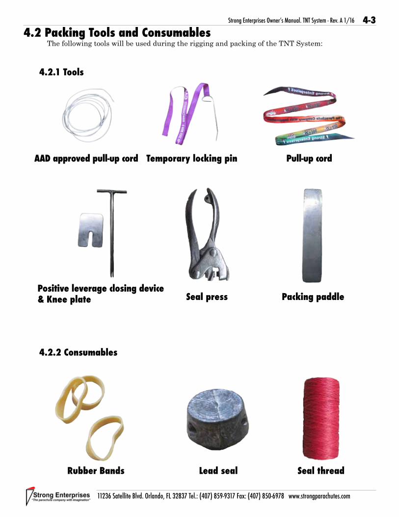
4.2 Packing Tools and ConsumablesThe following tools will be used during the rigging and packing of the TNT System:
4.2.1 Tools
4.2.2 Consumables
AAD approved pull-up cord Temporary locking pin Pull-up cord
Packing paddleSeal pressPositive leverage closing device & Knee plate
Lead seal Seal threadRubber Bands

4-4
11236 Satellite Blvd. Orlando, FL 32837 Tel.: (407) 859-9317 Fax: (407) 850-6978 www.strongparachutes.com
Strong Enterprises Owner’s Manual. TNT System - Rev. A 1/16
4.3 Preparing the Reserve Canopy4.3.1 AAD Installation
All AAD channels and pockets are factory-stitched into the rig and no modifications are necessary. Installation requires no tools and can be accomplished by a senior or master rigger using the following technique. For the current list of approved AAD’s see the “Approved Components List” available on the website.
4.3.1.1 Following manufacturer instructions, test the unit before installation.
4.3.1.2 Place the processing unit in pouch.
4.3.1.3Route control unit into the channel.
4.3.1.4Run control unit through channel and up to top of the container.

4-5
11236 Satellite Blvd. Orlando, FL 32837 Tel.: (407) 859-9317 Fax: (407) 850-6978 www.strongparachutes.com
Strong Enterprises Owner’s Manual. TNT System - Rev. A 1/16
4.3.1.5Route control unit through second channel located between subflaps and pin protector flap.
4.3.1.6Place control unit into elastic pocket located in the center of the pin protector flap.
4.3.1.7Make sure to route control unit so that when pin protector flap is closed unit display is visible through clear plastic window.

4-6
11236 Satellite Blvd. Orlando, FL 32837 Tel.: (407) 859-9317 Fax: (407) 850-6978 www.strongparachutes.com
Strong Enterprises Owner’s Manual. TNT System - Rev. A 1/16
4.3.1.8Next route single pin cutter into same channel as control unit.
4.3.1.9Run cutter down through channel and then through second channel located in bottom of reserve pack tray.
4.3.1.10Cutter will exit channel at open end of pack tray next to right side flap.
4.3.1.11Run cutter through channel located on right side flap.

4-7
11236 Satellite Blvd. Orlando, FL 32837 Tel.: (407) 859-9317 Fax: (407) 850-6978 www.strongparachutes.com
Strong Enterprises Owner’s Manual. TNT System - Rev. A 1/16
4.3.1.12At end of channel route cutter through elastic keeper.
4.3.1.13Elastic keeper will hold cutter positioned over center of grommet.
4.3.1.14All wires and cables should be left with enough slack to allow movement of control unit and cutter. Any excess cables can be loosely coiled under Velcro cover of processing unit pouch.

4-8
11236 Satellite Blvd. Orlando, FL 32837 Tel.: (407) 859-9317 Fax: (407) 850-6978 www.strongparachutes.com
Strong Enterprises Owner’s Manual. TNT System - Rev. A 1/16
4.3.1.15Secure Velcro cover over cables.
4.3.1.16After installation there should be no loose cables in the reserve pack tray.
4.3.2 Attaching Pilot Chute
4.3.2.1Route end of bridle from freebag through loops at base of reserve pilot chute.

4-9
11236 Satellite Blvd. Orlando, FL 32837 Tel.: (407) 859-9317 Fax: (407) 850-6978 www.strongparachutes.com
Strong Enterprises Owner’s Manual. TNT System - Rev. A 1/16
4.3.2.2Bring bridle loop to top of pilot chute and thread over top of pilot chute.
4.3.2.3Work loop to base of pilot chute and pull bridle tight to lock in place.
4.3.3 Preparing the Freebag
4.3.3.1Place bungee loops through grommets on freebag sub flap. Then place four rubber bands on each side flap of the freebag.
! WARNING !This reserve deployment bag assembly must not be attached to the
reserve canopy.

4-10
11236 Satellite Blvd. Orlando, FL 32837 Tel.: (407) 859-9317 Fax: (407) 850-6978 www.strongparachutes.com
Strong Enterprises Owner’s Manual. TNT System - Rev. A 1/16
4.3.3.2Larks head bungee loops with chokers on each of the tabs on outside of freebag.
4.3.3.3Run a pull up cord through the grommets located in the center of the freebag, and tie in a loose knot. This will be used to pull the closing loop through the freebag.
4.3.4 Loop and Pull up Cord
4.3.4.1Place hesitater loop through center grommet on reserve sub flap. Then place a AAD approved pull up cord through closing loop.
4-11
11236 Satellite Blvd. Orlando, FL 32837 Tel.: (407) 859-9317 Fax: (407) 850-6978 www.strongparachutes.com
Strong Enterprises Owner’s Manual. TNT System - Rev. A 1/16
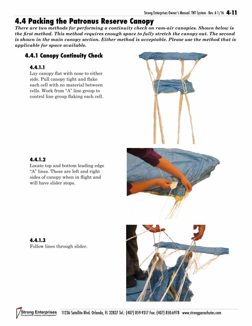
4.4.1 Canopy Continuity Check
4.4.1.1Lay canopy flat with nose to either side. Pull canopy tight and flake each cell with no material between cells. Work from “A” line group to control line group flaking each cell.
4.4.1.2 Locate top and bottom leading edge “A” lines. These are left and right sides of canopy when in flight and will have slider stops.
4.4.1.3 Follow lines through slider.
4.4 Packing the Patronus Reserve CanopyThere are two methods for performing a continuity check on ram-air canopies. Shown below is
the first method. This method requires enough space to fully stretch the canopy out. The second is shown in the main canopy section. Either method is acceptable. Please use the method that is
applicable for space available.

4-12
11236 Satellite Blvd. Orlando, FL 32837 Tel.: (407) 859-9317 Fax: (407) 850-6978 www.strongparachutes.com
Strong Enterprises Owner’s Manual. TNT System - Rev. A 1/16
4.4.1.4Follow to outside edge of front risers.
4.4.1.5Locate top and bottom “D” lines. Left and right stabilizers of canopy.
4.4.1.6 Follow lines through slider.
4.4.1.7Follow to outside edge of rear risers.

4-13
11236 Satellite Blvd. Orlando, FL 32837 Tel.: (407) 859-9317 Fax: (407) 850-6978 www.strongparachutes.com
Strong Enterprises Owner’s Manual. TNT System - Rev. A 1/16
4.4.1.8Locate tail control lines on each side of canopy.
4.4.1.9Follow through slider grommets.
4.4.1.10Follow to right and left toggles.Make sure they are free and clear.
4.4.2 Stowing the Brakes
4.4.2.1Pull control lines through guide ring until cat-eye is below guide ring.
STOP: Rigger check.
1. All lines clear.2. Canopy not twisted or inverted.

4-14
11236 Satellite Blvd. Orlando, FL 32837 Tel.: (407) 859-9317 Fax: (407) 850-6978 www.strongparachutes.com
Strong Enterprises Owner’s Manual. TNT System - Rev. A 1/16
4.4.2.2Place toggle into cat-eye below guide ring.
4.4.2.3Place tip of toggle into elastic keeper located above the guide ring.
4.4.2.4Pull any excess line back through guide ring towards canopy. This should leave only one loop of line below the guide ring.
4-15
11236 Satellite Blvd. Orlando, FL 32837 Tel.: (407) 859-9317 Fax: (407) 850-6978 www.strongparachutes.com
Strong Enterprises Owner’s Manual. TNT System - Rev. A 1/16
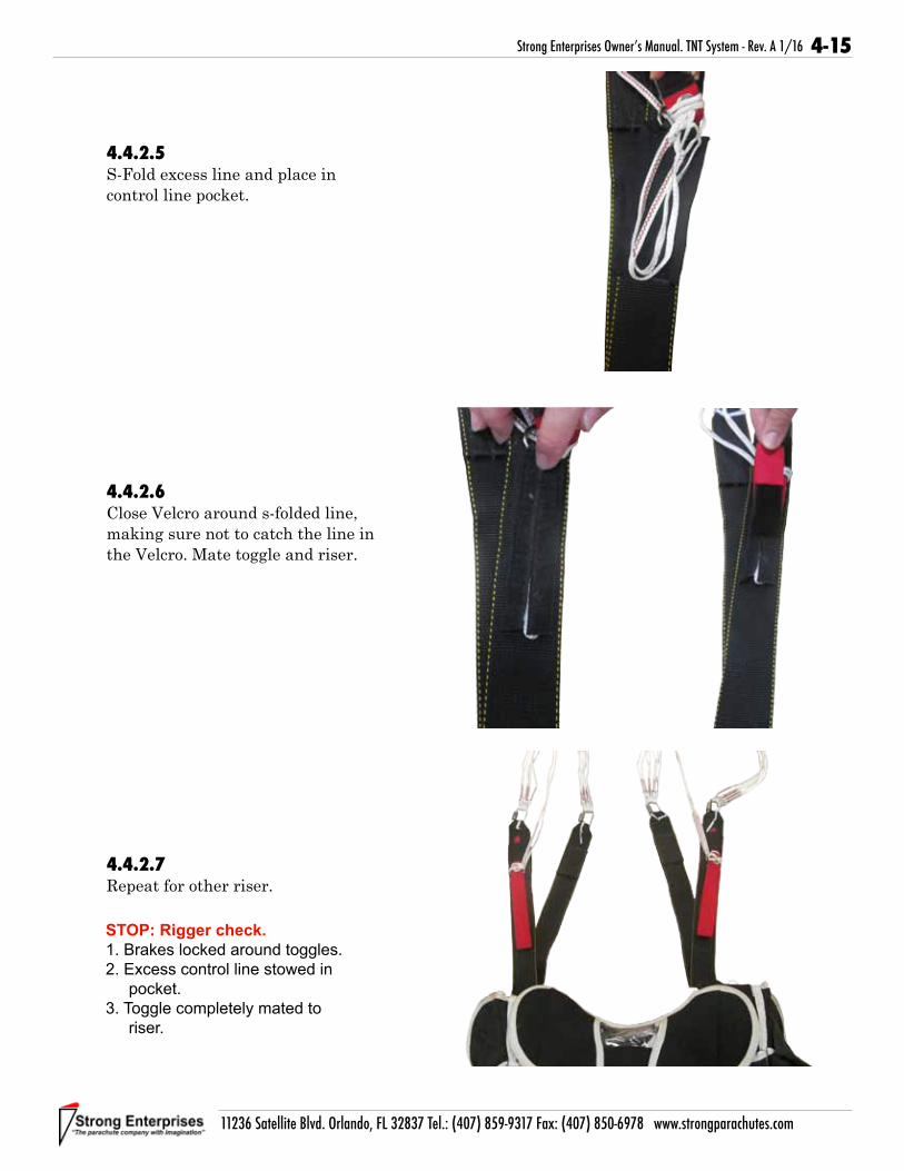
4.4.2.5S-Fold excess line and place in control line pocket.
4.4.2.6Close Velcro around s-folded line, making sure not to catch the line in the Velcro. Mate toggle and riser.
4.4.2.7Repeat for other riser.
STOP: Rigger check.
1. Brakes locked around toggles.2. Excess control line stowed in
pocket.3. Toggle completely mated to
riser.

4-16
11236 Satellite Blvd. Orlando, FL 32837 Tel.: (407) 859-9317 Fax: (407) 850-6978 www.strongparachutes.com
Strong Enterprises Owner’s Manual. TNT System - Rev. A 1/16
4.4.3 Folding the Canopy
4.4.3.1Grasp control and suspension lines keeping front riser, rear riser and control lines separate.
4.4.3.2Run lines to canopy keeping right and left sides separate. Keep flag slider near canopy.
4.4.3.3Place lines over shoulder or on a hook with canopy tail facing away from container. Clear all cells at leading edge and keep together as a group.
NOTE!
Photos will show canopy on a hook.
Front Riser (A & B Lines)
Rear Riser (C & D Lines)
Control Lines

4-17
11236 Satellite Blvd. Orlando, FL 32837 Tel.: (407) 859-9317 Fax: (407) 850-6978 www.strongparachutes.com
Strong Enterprises Owner’s Manual. TNT System - Rev. A 1/16
4.4.3.4Gently pull each line tab towards the canopy to remove excess slack from lines. Once clear all “A” line tabs should be lined up evenly.
4.4.3.5While controlling “A” line groups gently pull “B” line tabs to remove excess slack from lines. Then flake material between line groups to the outside.
4.4.3.6Continue pulling slack from each line group and flaking material between “B” and “C” and “C” and “D” line groups.
A
B
B
C

4-18
11236 Satellite Blvd. Orlando, FL 32837 Tel.: (407) 859-9317 Fax: (407) 850-6978 www.strongparachutes.com
Strong Enterprises Owner’s Manual. TNT System - Rev. A 1/16
4.4.3.7Once all groups are flaked, lines should be to the center and material should be outside.
4.4.3.8Take the two inner control lines and fold until line tabs are about even with outer three. Double wrap the lines in the rubber band located on the third line tab.
Repeat for other side
Note!
The easiest way to stow the control lines is to grasp lines even with third line tab and wrap around fingers until line tabs are about even.
4.4.3.9Flake flag slider to the front and rear of canopy between line groups.
4-19
11236 Satellite Blvd. Orlando, FL 32837 Tel.: (407) 859-9317 Fax: (407) 850-6978 www.strongparachutes.com
Strong Enterprises Owner’s Manual. TNT System - Rev. A 1/16
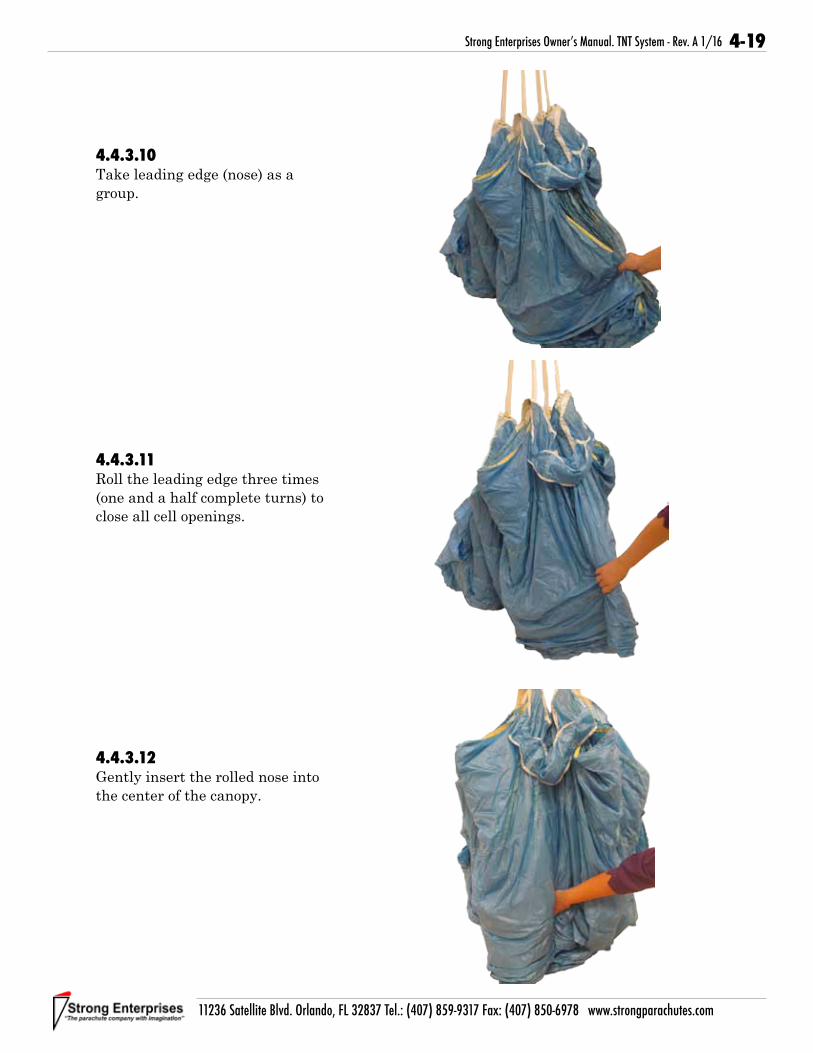
4.4.3.10Take leading edge (nose) as a group.
4.4.3.11Roll the leading edge three times (one and a half complete turns) to close all cell openings.
4.4.3.12Gently insert the rolled nose into the center of the canopy.

4-20
11236 Satellite Blvd. Orlando, FL 32837 Tel.: (407) 859-9317 Fax: (407) 850-6978 www.strongparachutes.com
Strong Enterprises Owner’s Manual. TNT System - Rev. A 1/16
4.4.3.13Straighten flag of slider in front of canopy nose.
4.4.3.14Take the center of the tail and bring it up to suspension lines above slider grommets and wrap around to nose. Match seams from each side in order to keep canopy even.
Note!
The center of the tail is located just to the left of the Data Label.
4.4.3.15Roll the tail together keeping material as even as possible in order to create a cocoon around the canopy.
STOP: Rigger check.
1. All Cells flaked.2. Control lines stowed.3. Flag slider is in place between
line groups.4. Nose is rolled and placed in
center of canopy.
Seams Even

4-21
11236 Satellite Blvd. Orlando, FL 32837 Tel.: (407) 859-9317 Fax: (407) 850-6978 www.strongparachutes.com
Strong Enterprises Owner’s Manual. TNT System - Rev. A 1/16
4.4.3.16Hold the lines with one hand, the rolled tail with other hand and place canopy gently on the floor with rolled edge to the floor. Make sure that lines stay tight and canopy stays neatly rolled.
4.4.3.17Roll the sides of the canopy under until the cocooned canopy is the width of the freebag. Compress canopy removing air working away from container. Finish with a tight cocoon.
4.4.3.18Grasp lines and canopy tail and create an s-fold in the canopy with the lines on top.

4-22
11236 Satellite Blvd. Orlando, FL 32837 Tel.: (407) 859-9317 Fax: (407) 850-6978 www.strongparachutes.com
Strong Enterprises Owner’s Manual. TNT System - Rev. A 1/16
4.4.3.19With one hand holding the rolled tail seam fold canopy back toward container without removing underneath hand.
4.4.4.1Position freebag so that elastic bridle stows are facing up.
4.4.4.2Place the canopy into the freebag. Be sure to push the folded end all the way to the bottom of the freebag. Be careful not to unfold canopy.
Side View of Folds
Bridle stows
4.4.4 Packing Canopy in Freebag
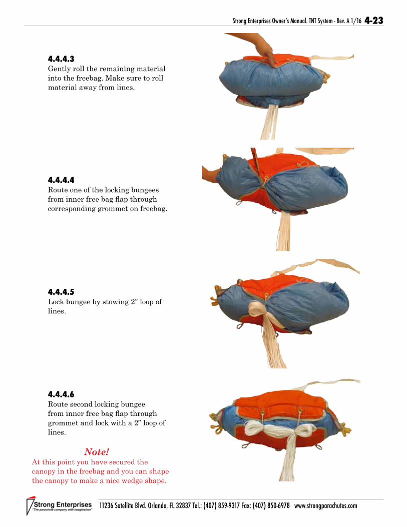
4-23
11236 Satellite Blvd. Orlando, FL 32837 Tel.: (407) 859-9317 Fax: (407) 850-6978 www.strongparachutes.com
Strong Enterprises Owner’s Manual. TNT System - Rev. A 1/16
4.4.4.3Gently roll the remaining material into the freebag. Make sure to roll material away from lines.
4.4.4.4Route one of the locking bungees from inner free bag flap through corresponding grommet on freebag.
4.4.4.5Lock bungee by stowing 2” loop of lines.
4.4.4.6Route second locking bungee from inner free bag flap through grommet and lock with a 2” loop of lines.
Note!
At this point you have secured the canopy in the freebag and you can shape the canopy to make a nice wedge shape.

4-24
11236 Satellite Blvd. Orlando, FL 32837 Tel.: (407) 859-9317 Fax: (407) 850-6978 www.strongparachutes.com
Strong Enterprises Owner’s Manual. TNT System - Rev. A 1/16
4.4.4.7Stand the freebag up.
4.4.4.8Take all suspension lines and hold them even with the seam of the top flap, opposite from last stow.
4.4.4.9Using the seamed edge of the flap as a reference make a loop and double wrap stow with rubber band closest to first stow from side flap. Loops should be approximately1 1/2” in length.
Note!
Make sure to pull rubber band stows toward lines creating tension. Do not just put around end of loop. This will keep tension on all lines evenly throughout deployment minimizing travel and giving a smooth release of lines and canopy.

4-25
11236 Satellite Blvd. Orlando, FL 32837 Tel.: (407) 859-9317 Fax: (407) 850-6978 www.strongparachutes.com
Strong Enterprises Owner’s Manual. TNT System - Rev. A 1/16
4.4.4.10Continue to stow lines across the top of the bag. Make sure to double wrap all line stows.
4.4.4.11When you have approximately 4’ of line remaining stop stowing lines.
4.4.4.12Close outer flap over lines. Route outside bungee and choker opposite of last stow up though corresponding grommet.
STOP: Rigger check.
1. Line stows start with locking stows.2. All line stows using rubber bands
are double wrapped.3. All line stows do not extend past
sides of freebag.

4-26
11236 Satellite Blvd. Orlando, FL 32837 Tel.: (407) 859-9317 Fax: (407) 850-6978 www.strongparachutes.com
Strong Enterprises Owner’s Manual. TNT System - Rev. A 1/16
4.4.4.13Lock with approximately 2” of line. Make sure to pull choker tight against lines.
Note!
If choker is above grommet it will come off and be lost when deployed.
4.4.4.14Continue with opposite side bungee and choker, then end with middle bungee and choker.
4.4.4.15Freebag should now be next to container and is ready to pack into container.

4-27
11236 Satellite Blvd. Orlando, FL 32837 Tel.: (407) 859-9317 Fax: (407) 850-6978 www.strongparachutes.com
Strong Enterprises Owner’s Manual. TNT System - Rev. A 1/16
4.5.1 Closing the Sub Flaps
4.5.1.1Place the risers and freebag in the reserve pack tray, so that the lines are to the bottom.
4.5.1.2Flip the freebag onto the main pack tray and spread the risers along the bottom of the pack tray so that the risers form a “V” shape and the links are spread out.
4.5.1.3Tie the pull up cord from the closing loop to the cord that goes through the freebag with a small knot. Make sure that the pull up cord is clear of all suspension lines.
4.5 Closing the Reserve Container

4-28
11236 Satellite Blvd. Orlando, FL 32837 Tel.: (407) 859-9317 Fax: (407) 850-6978 www.strongparachutes.com
Strong Enterprises Owner’s Manual. TNT System - Rev. A 1/16
4.5.1.4Fold the freebag back on top of the risers. Keep the lines neat while folding the freebag back over the risers.
4.5.1.5Bring pull up cord through the freebag until closing loop is through grommet. Lock with a temporary locking pin.
4.5.1.6Route pull up cord through grommet on lower subflap. Pull closing loop through grommet and lock with a temporary locking pin.

4-29
11236 Satellite Blvd. Orlando, FL 32837 Tel.: (407) 859-9317 Fax: (407) 850-6978 www.strongparachutes.com
Strong Enterprises Owner’s Manual. TNT System - Rev. A 1/16
4.5.1.7Route pull up cord through small grommet on upper sub flap. Pull closing loop through grommet and lock with a temporary locking pin. Make sure that freebag bridle is to the left side of the closing loop.
4.5.1.8
Place a pull up cord through the hesitater loop on the bottom sub flap and bring up through larger grommet on upper sub flap.
4.5.1.9
Make a bight of the bridle no more than 1-1/2” and place through the elastic hesitater loop to lock sub flaps closed.

4-30
11236 Satellite Blvd. Orlando, FL 32837 Tel.: (407) 859-9317 Fax: (407) 850-6978 www.strongparachutes.com
Strong Enterprises Owner’s Manual. TNT System - Rev. A 1/16
4.5.2.1 Open the cover flap on left side of upper subflap.
4.5.2.2 S-fold pilot chute bridle so that folds are approximately the same length as the cover flap. Stop stowing bridle when 6” from ring stop on bridle.
4.5.2.3 Close the cover flap over the bridle to hold in place.
4.5.2.4 Fold the ring stop in half so that the ring and yellow flex pin are on top and the floating ring is positioned at the bottom of the right cover flap.
4.5.2 Stowing the Pilot Chute and Attaching the Air Anchor

4-31
11236 Satellite Blvd. Orlando, FL 32837 Tel.: (407) 859-9317 Fax: (407) 850-6978 www.strongparachutes.com
Strong Enterprises Owner’s Manual. TNT System - Rev. A 1/16
4.5.2.5 Lay the Air Anchor on top of the bridle with the red locking loop and nylatron tab facing up.
4.5.2.6 Slide the small ring from the Air Anchor through the floating ring on the bridle.
4.5.2.7 Flip the small ring up over the floating ring.

4-32
11236 Satellite Blvd. Orlando, FL 32837 Tel.: (407) 859-9317 Fax: (407) 850-6978 www.strongparachutes.com
Strong Enterprises Owner’s Manual. TNT System - Rev. A 1/16
4.5.2.8 Bring the red locking loop down through the small ring.
4.5.2.9 Rotate the Air Anchor so that the red locking loop is facing down and run the red locking loop through the grommet.
4.5.2.10 Take the yellow flex pin from the bridle and insert through the red locking loop and into the channel located on the Air Anchor.
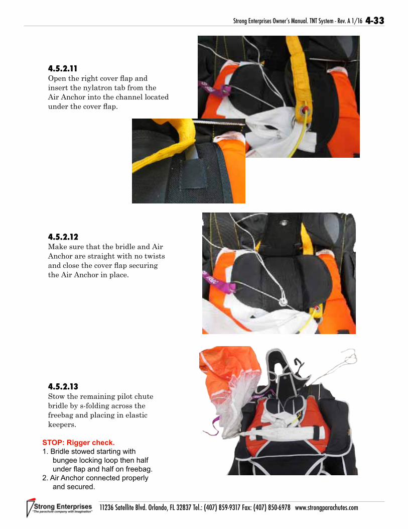
4-33
11236 Satellite Blvd. Orlando, FL 32837 Tel.: (407) 859-9317 Fax: (407) 850-6978 www.strongparachutes.com
Strong Enterprises Owner’s Manual. TNT System - Rev. A 1/16
4.5.2.11 Open the right cover flap and insert the nylatron tab from the Air Anchor into the channel located under the cover flap.
4.5.2.12 Make sure that the bridle and Air Anchor are straight with no twists and close the cover flap securing the Air Anchor in place.
4.5.2.13 Stow the remaining pilot chute bridle by s-folding across the freebag and placing in elastic keepers.
STOP: Rigger check.
1. Bridle stowed starting with bungee locking loop then half under flap and half on freebag.
2. Air Anchor connected properly and secured.

4-34
11236 Satellite Blvd. Orlando, FL 32837 Tel.: (407) 859-9317 Fax: (407) 850-6978 www.strongparachutes.com
Strong Enterprises Owner’s Manual. TNT System - Rev. A 1/16
4.5.2.14 Route pull up cord up from the bottom and out through the top of the pilot chute. Make sure that pull up cord goes through the center of pilot chute spring.
4.5.2.15 Place base of pilot chute centered over upper sub flap grommet and compress. Make sure that you don’t catch any material in the spring.
4.5.2.16 Roll material from top of pilot chute down to wrap around spring.

4-35
11236 Satellite Blvd. Orlando, FL 32837 Tel.: (407) 859-9317 Fax: (407) 850-6978 www.strongparachutes.com
Strong Enterprises Owner’s Manual. TNT System - Rev. A 1/16
4.5.2.17 Roll material from right and left sides in to wrap around spring.
4.5.2.18 Roll material from bottom up to wrap around spring. Be careful not to roll freebag bridle into pilot chute material.
4.5.3 Closing the top flaps
4.5.3.1Route pull up cord through AAD cutter and through grommet on right side flap. Pull closing loop through cutter and grommet and lock in place with temporary locking pin.

4-36
11236 Satellite Blvd. Orlando, FL 32837 Tel.: (407) 859-9317 Fax: (407) 850-6978 www.strongparachutes.com
Strong Enterprises Owner’s Manual. TNT System - Rev. A 1/16
4.5.3.2Route pull up cord through grommet on left side flap. Pull closing loop through grommet and lock in place with temporary locking pin.
4.5.3.3Route pull up cord through grommet on bottom flap. Pull closing loop through grommet and lock in place with temporary locking pin.
4.5.3.4Route pull up cord through grommet on top flap.
STOP: Rigger check.
1. Closing loop correctly routed. AAD cutter, right flap, left flap, bottom flap.

4-37
11236 Satellite Blvd. Orlando, FL 32837 Tel.: (407) 859-9317 Fax: (407) 850-6978 www.strongparachutes.com
Strong Enterprises Owner’s Manual. TNT System - Rev. A 1/16
4.5.3.5Remove all twists from Air Anchor lanyard. Route ripcord pin through ring on Air Anchor lanyard and guide ring on top flap.
4.5.3.6Pull closing loop through grommet and lock in place with ripcord pin. Remove pull up cord. To avoid possibly breaking closing loop, first route pull up cord under ripcord pin and then slowly remove pull up cord. Seal the pin and fill out the data card.
4.5.4 Closing pin cover flap
4.5.4.1Use a packing paddle and push reserve tuck flaps down between reserve risers and freebag.

4-38
11236 Satellite Blvd. Orlando, FL 32837 Tel.: (407) 859-9317 Fax: (407) 850-6978 www.strongparachutes.com
Strong Enterprises Owner’s Manual. TNT System - Rev. A 1/16
4.5.4.2Make sure there are no twists in the RSL lanyard and insert the two nylatron tuck tabs into the channels on the right riser cover.
4.5.4.3Stow the excess Air Anchor lanyard in the elastic keeper located above the top flap. Insert the lanyard from left to right.
4.5.4.4Stow the excess RSL lanyard in the elastic keeper on top of the excess from the Air Anchor. Make sure when stowing excess that the ring around the ripcord cable is not pulled tight.

4-39
11236 Satellite Blvd. Orlando, FL 32837 Tel.: (407) 859-9317 Fax: (407) 850-6978 www.strongparachutes.com
Strong Enterprises Owner’s Manual. TNT System - Rev. A 1/16
4.5.4.5Seal the reserve pin in accordance with local regulations. Fill out the packing data card. Close the pin protector flap by tucking the bottom into the pocket on the bottom flap and closing side tuck tabs around the top flap.
4.5.4.6The riser covers are magnetic and can either be tucked into the pockets on the pin protector flap or closed over the pockets.
STOP: Rigger check.
1. Tuck tabs between risers and freebag.
2. RSL/Air Anchor Lanyard stowed.
3. Pin protector flap secure.

4-40
11236 Satellite Blvd. Orlando, FL 32837 Tel.: (407) 859-9317 Fax: (407) 850-6978 www.strongparachutes.com
Strong Enterprises Owner’s Manual. TNT System - Rev. A 1/16
4.6.1 Attaching Y-line Drogue
4.6.1.1Lay ALS bag flat with #3 flap and drogue bridle with the drogue release ring facing up. Install rubber bumper over bridle. Attach Kevlar drogue bridle to #5 Rapide link on top of the ALS bag. Tighten nut, finger tight plus 1/4 turn with a 3/8” wrench.
4.6.1.2Slide plastic bumper over link and handtack in place with two turns through the link bumper and the bridle.
4.6.1.3Feed Y-lines through #4 grommet on either side of the Rapide link.
4.6 Preparing the Main Canopy
Drogue Release Ring
#3 Flap

4-41
11236 Satellite Blvd. Orlando, FL 32837 Tel.: (407) 859-9317 Fax: (407) 850-6978 www.strongparachutes.com
Strong Enterprises Owner’s Manual. TNT System - Rev. A 1/16
4.6.1.4Attach y-lines to the #5 Rapide link on top of the canopy. Tighten nut, finger tight plus 1/4 turn with a 3/8” wrench.
4.6.2 Attaching Main Risers
4.6.2.1Ensure there are no twists in the line groups by taking each line group and control line group in your hands and follow them up to canopy. Remove all twists as you go.
4.6.2.2Lay risers with toggle side facing up above the container. The riser with the Swedish link will attach to the right side. Place the medium ring from the risers down through the 3-D ring.

4-42
11236 Satellite Blvd. Orlando, FL 32837 Tel.: (407) 859-9317 Fax: (407) 850-6978 www.strongparachutes.com
Strong Enterprises Owner’s Manual. TNT System - Rev. A 1/16
4.6.2.3Next bring the small ring from the riser down through the medium ring.
4.6.2.4Then bring the red loop around the small ring only and run it through the grommet.
Note!
Make sure that small ring ONLY goes through medium ring and that red loop ONLY goes through small ring.
4.6.2.5Run the red loop through the fitting on the end of the housing.

4-43
11236 Satellite Blvd. Orlando, FL 32837 Tel.: (407) 859-9317 Fax: (407) 850-6978 www.strongparachutes.com
Strong Enterprises Owner’s Manual. TNT System - Rev. A 1/16
4.6.2.6Lock in place using the cutaway cable.
4.6.2.7The excess cable can then be put into the channel on the risers.

4-44
11236 Satellite Blvd. Orlando, FL 32837 Tel.: (407) 859-9317 Fax: (407) 850-6978 www.strongparachutes.com
Strong Enterprises Owner’s Manual. TNT System - Rev. A 1/16
4.6.2.8Repeat for the other side.
4.6.2.9Connect RSL lanyard to the snap shackle located on the right riser.
Note!
Use of RSL is optional.
Note!
Air Anchor will not function if RSL lanyard is not hooked up.
4.6.3 Install Closing Loops
4.6.3.1Place one closing loop through the grommet on the bottom closing flap. Place one closing loop through the bottom grommet on the right side flap. Same length is used in both locations.

4-45
11236 Satellite Blvd. Orlando, FL 32837 Tel.: (407) 859-9317 Fax: (407) 850-6978 www.strongparachutes.com
Strong Enterprises Owner’s Manual. TNT System - Rev. A 1/16
4.7.1 Continuity Check
4.7.1.1Lay canopy flat out with nose (leading edge) facing down and tail on top. Locate all tail control lines. Grasp left and right lines and follow towards risers.
4.7.1.2Follow through slider.
4.7.1.3End at toggles, making sure there are no twists.
4.7 Packing the Main CanopyThere are two methods for performing a continuity check on ram-air canopies. Shown below is the second method. This method is used when space is a concern. The first is shown in the reserve canopy section. Either method is acceptable. Please use the method that is applicable for space available.

4-46
11236 Satellite Blvd. Orlando, FL 32837 Tel.: (407) 859-9317 Fax: (407) 850-6978 www.strongparachutes.com
Strong Enterprises Owner’s Manual. TNT System - Rev. A 1/16
4.7.1.4Grasp left and right stabilizer lines “C” and “D”.
4.7.1.5Follow through slider.
4.7.1.6Follow to outside edge of rear risers.
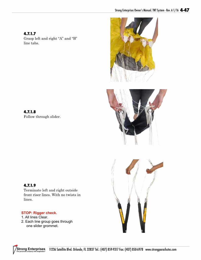
4-47
11236 Satellite Blvd. Orlando, FL 32837 Tel.: (407) 859-9317 Fax: (407) 850-6978 www.strongparachutes.com
Strong Enterprises Owner’s Manual. TNT System - Rev. A 1/16
4.7.1.7Grasp left and right “A” and “B” line tabs.
4.7.1.8Follow through slider.
4.7.1.9Terminate left and right outside front riser lines. With no twists in lines.
STOP: Rigger check.
1. All lines Clear.2. Each line group goes through
one slider grommet.

4-48
11236 Satellite Blvd. Orlando, FL 32837 Tel.: (407) 859-9317 Fax: (407) 850-6978 www.strongparachutes.com
Strong Enterprises Owner’s Manual. TNT System - Rev. A 1/16
4.7.2 Setting the Brakes
4.7.2.1Pull the control lines through the guide ring until the brake loop is just below the steel guide ring on the rear riser.
4.7.2.2Bring the locking loop (located on the riser) up through the guide ring.
4.7.2.3Bring the locking loop up through the brake loop.

4-49
11236 Satellite Blvd. Orlando, FL 32837 Tel.: (407) 859-9317 Fax: (407) 850-6978 www.strongparachutes.com
Strong Enterprises Owner’s Manual. TNT System - Rev. A 1/16
4.7.2.4Insert the tip of the toggle through the locking loop.
4.7.2.5Stow in elastic keeper located on riser.
4.7.2.6Clear the second control line by gently pulling the line back through the ring.
Note!
Lines are clear when the red zig zag stitching on each line is showing.

4-50
11236 Satellite Blvd. Orlando, FL 32837 Tel.: (407) 859-9317 Fax: (407) 850-6978 www.strongparachutes.com
Strong Enterprises Owner’s Manual. TNT System - Rev. A 1/16
CAUTIONTHE LOOP ON THE RISER MUST BE USED IN
ORDER TO KEEP THE BRAKE LINE LOOP FROM DIGGING INTO THE SIDE OF THE TOGGLE.
4.7.2.7S-fold the excess control line and stow in the elastic keeper under the toggle.
4.7.2.8Snap the toggle to the riser, then fold the toggle between the middle and lower hand grip loops and tuck the lower end of the toggle into the toggle pocket located on the riser.
4.7.2.9Repeat procedure on the opposite riser.
STOP: Rigger check.
1. Brakes locked.2. Excess control line stowed in
elastic.3. Toggles snapped and stowed.

4-51
11236 Satellite Blvd. Orlando, FL 32837 Tel.: (407) 859-9317 Fax: (407) 850-6978 www.strongparachutes.com
Strong Enterprises Owner’s Manual. TNT System - Rev. A 1/16
4.7.3 Flaking the Canopy
4.7.3.1At the risers, pick up the lines and use your fingers to separate the front lines, rear lines, and control lines.
4.7.3.2While facing the canopy, and still using your fingers to keep the lines separated, walk forward pushing the slider ahead of you until it is seated against its stops.
Note!At this point you may use a hook to hold the canopy in place or you may put the canopy over your shoulder to hold it.
4.7.3.3Flake the nose. This is done by running a hand down each cell and pulling the cell slightly. This will also align all “A” line tabs so they are even.

4-52
11236 Satellite Blvd. Orlando, FL 32837 Tel.: (407) 859-9317 Fax: (407) 850-6978 www.strongparachutes.com
Strong Enterprises Owner’s Manual. TNT System - Rev. A 1/16
4.7.3.4While controlling “A” line groups gently pull “B” line tabs to remove excess slack from lines. Then flake material between line groups to the outside.
4.7.3.5Continue pulling slack from each line group and flaking material between “B” and “C” and “C” and “D” line groups.
4.7.3.6On each side of the canopy attach a rubber band to the third control line attachment tab from the outside. Stow the two left inner control lines in the left rubber band and the two right inner control lines in the right rubber band, using a double wrap.
Note!
Failure to stow inner control lines greatly increases the chance of a “line over” malfunction.
Note!
The easiest way to stow the control lines is to grasp lines even with third line tab and wrap around fingers until line tabs are about even.

4-53
11236 Satellite Blvd. Orlando, FL 32837 Tel.: (407) 859-9317 Fax: (407) 850-6978 www.strongparachutes.com
Strong Enterprises Owner’s Manual. TNT System - Rev. A 1/16
4.7.3.7In order to soften the openings on new canopies you can roll the nose. After the canopy is broken in there is no need to do anything with the nose. Let it hang down naturally, grasp it and push it into the canopy folds a few inches.
4.7.3.8Flake flag slider to the front and rear of canopy between line groups.
4.7.3.9Take the center of the tail and bring it up to suspension lines above slider grommets and wrap around to nose.
Note!
The center of the tail is located just to the left of the Data Label.
STOP: Rigger check.
1. All Cells flaked.2. Control lines stowed.3. Flag slider is in place between
line groups.4. Nose is tucked in center of
canopy.

4-54
11236 Satellite Blvd. Orlando, FL 32837 Tel.: (407) 859-9317 Fax: (407) 850-6978 www.strongparachutes.com
Strong Enterprises Owner’s Manual. TNT System - Rev. A 1/16
4.7.3.10Roll the tail together keeping material as even as possible in order to create a cocoon around the canopy. Match seams from each side in order to keep canopy even.
4.7.3.11While keeping the tail seams held firmly in your hand, carefully lay the canopy down flat on the packing surface with the lines taut.
4.7.3.12Purge the air from the canopy and dress to the approximate width of the deployment bag.
Seams Even

4-55
11236 Satellite Blvd. Orlando, FL 32837 Tel.: (407) 859-9317 Fax: (407) 850-6978 www.strongparachutes.com
Strong Enterprises Owner’s Manual. TNT System - Rev. A 1/16
4.7.3.13S-fold the lower canopy by grasping at the lines and folding up approximately 10-inches.
4.7.3.14Fold the upper canopy back over the first fold keeping everything neat and secure. Then fold the canopy back on top of itself.
4.7.4.1While controlling the canopy, slide the canopy into the ALS bag with the 3 locking bungee stows toward the packing surface. Make sure to fill out the corners.
4.7.4 Placing the canopy in the ALS bag
Side View of Folds

4-56
11236 Satellite Blvd. Orlando, FL 32837 Tel.: (407) 859-9317 Fax: (407) 850-6978 www.strongparachutes.com
Strong Enterprises Owner’s Manual. TNT System - Rev. A 1/16
4.7.4.2Make your first line stow by bringing the center inner rubber band up through the center grommet.
4.7.4.3Lock in place with a bight of suspension line.
4.7.4.4Following the direction of the stow bring the inner rubber band up through the side grommet. Lock in place with a bight of suspension line.

4-57
11236 Satellite Blvd. Orlando, FL 32837 Tel.: (407) 859-9317 Fax: (407) 850-6978 www.strongparachutes.com
Strong Enterprises Owner’s Manual. TNT System - Rev. A 1/16
4.7.4.5 Continue with the remaining side stows, locking the canopy in the bag.
Note!If you have a Velcro ALS bag you would now close the Velcro around the canopy.
4.7.4.6Stow the suspension lines using rubber bands on sides of the bag. Keep stows neat and only the width of the bag.
STOP: Rigger check.
1. Line stows start with inner stows.2. All side line stows are double
wrapped.3. All line stows do not extend past
sides of ALS bag.

4-58
11236 Satellite Blvd. Orlando, FL 32837 Tel.: (407) 859-9317 Fax: (407) 850-6978 www.strongparachutes.com
Strong Enterprises Owner’s Manual. TNT System - Rev. A 1/16
4.7.4.7 Stop stowing suspension lines when within about 4 feet of the links.
4.7.4.8 Fold the ALS flap down over the suspension lines. Starting with the outside stows bring the bungee loop through the outside grommet.
4.7.4.9 Lock in place with a bight of suspension line.

4-59
11236 Satellite Blvd. Orlando, FL 32837 Tel.: (407) 859-9317 Fax: (407) 850-6978 www.strongparachutes.com
Strong Enterprises Owner’s Manual. TNT System - Rev. A 1/16
4.7.4.10 Continue with the opposite outside stow.
4.7.4.11 Finish with the center stow.
4.7.4.12 Bring the deployment bag over the reserve and place into the main pack tray with the lines facing down.

4-60
11236 Satellite Blvd. Orlando, FL 32837 Tel.: (407) 859-9317 Fax: (407) 850-6978 www.strongparachutes.com
Strong Enterprises Owner’s Manual. TNT System - Rev. A 1/16
4.7.4.13 After the canopy has been jumped, you will need to cock the drogue. This is done by grasping the drogue deployment pud (located at the apex of the drogue canopy) and extending the drogue bridle to its fullest length.
4.7.5 Closing the Container
4.7.5.1 Dress the risers neatly along the outside of the reserve container and close the magnetic riser covers.
4.7.5.2 Rotate the deployment bag up and lay the lines neatly in the bottom of the pack tray.

4-61
11236 Satellite Blvd. Orlando, FL 32837 Tel.: (407) 859-9317 Fax: (407) 850-6978 www.strongparachutes.com
Strong Enterprises Owner’s Manual. TNT System - Rev. A 1/16
4.7.5.3 Seat the bottom of the bag in the pack try and push the top corners of the ALS bag into the top corners of the main pack tray so that the ALS bag is laying flat.
4.7.5.4 Route drogue bridle to bottom of container and back towards top.
4.7.5.5 Locate the ring on the drogue bridle and lay the bridle and the ring on the ALS bag so that the flex pin is on the right side of the drogue riser.Attach the drogue bridle by placing the medium ring from the drogue riser (located between the main and reserve pack trays) through the ring from the drogue bridle. Next place the small ring through the medium ring.
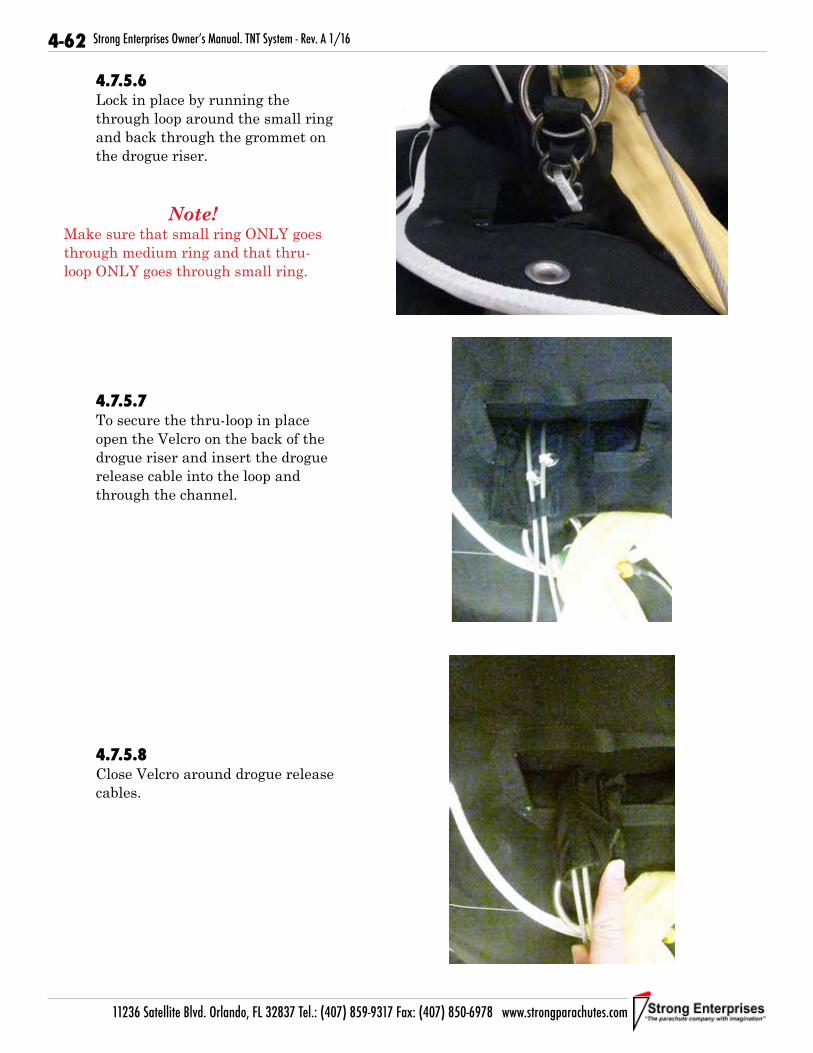
4-62
11236 Satellite Blvd. Orlando, FL 32837 Tel.: (407) 859-9317 Fax: (407) 850-6978 www.strongparachutes.com
Strong Enterprises Owner’s Manual. TNT System - Rev. A 1/16
4.7.5.6 Lock in place by running the through loop around the small ring and back through the grommet on the drogue riser.
Note!
Make sure that small ring ONLY goes through medium ring and that thru-loop ONLY goes through small ring.
4.7.5.7 To secure the thru-loop in place open the Velcro on the back of the drogue riser and insert the drogue release cable into the loop and through the channel.
4.7.5.8Close Velcro around drogue release cables.

4-63
11236 Satellite Blvd. Orlando, FL 32837 Tel.: (407) 859-9317 Fax: (407) 850-6978 www.strongparachutes.com
Strong Enterprises Owner’s Manual. TNT System - Rev. A 1/16
4.7.5.9Insert the flex pin located on the drogue bridle into the channel located on the drogue riser.
4.7.5.10Route a pull up cord through the closing loop on the bottom flap and through the grommet on the top flap. Pull closing loop through grommet.
4.7.5.11Close the right side flap by bringing the pull up cord through the grommet on the right side closing flap and pulling closing loop through grommet.
Note!
Make sure that drogue bridle is exiting to the right of the top flap.

4-64
11236 Satellite Blvd. Orlando, FL 32837 Tel.: (407) 859-9317 Fax: (407) 850-6978 www.strongparachutes.com
Strong Enterprises Owner’s Manual. TNT System - Rev. A 1/16
4.7.5.12Close the left flap by bringing the pull up cord through the uppermost grommet on the left closing flap and pulling the closing loop through.
4.7.5.13Lock in place using the flex pin from the drogue bridle. Remove the pull up cord by gently pulling it out. Do not route the cord under the flex pin as, over time, doing so will create a groove in the coating of the flex pin and decrease it’s life.
4.7.5.14Bring the closing loop from the right side flap up through the bottom grommet on the left side flap.

4-65
11236 Satellite Blvd. Orlando, FL 32837 Tel.: (407) 859-9317 Fax: (407) 850-6978 www.strongparachutes.com
Strong Enterprises Owner’s Manual. TNT System - Rev. A 1/16
4.7.5.15Lock in place with the flex pin. Remove the pull up cord.
Note!
Second loop is loose and is a redundant safety feature of the two-loop system.
4.7.5.16
Stow the excess flex pin in the tuck pocket.
4.7.5.17
Lay the drogue riser between the main and reserve pack trays. Route drogue bridle out right side of container.
STOP: Rigger check.
1. Drogue cocked.2. Drogue 3-ring assembled and
locked properly.3. Flex pin through both closing loops.

4-66
11236 Satellite Blvd. Orlando, FL 32837 Tel.: (407) 859-9317 Fax: (407) 850-6978 www.strongparachutes.com
Strong Enterprises Owner’s Manual. TNT System - Rev. A 1/16
4.7.5.18 Close the main flap and open the drogue bridle cover flap.
4.7.5.19Route the bridle down the container in the channel and close the bridle cover flap by tucking it into the space provided.
4.7.5.20Close the center flap by tucking it under the main closing flaps.
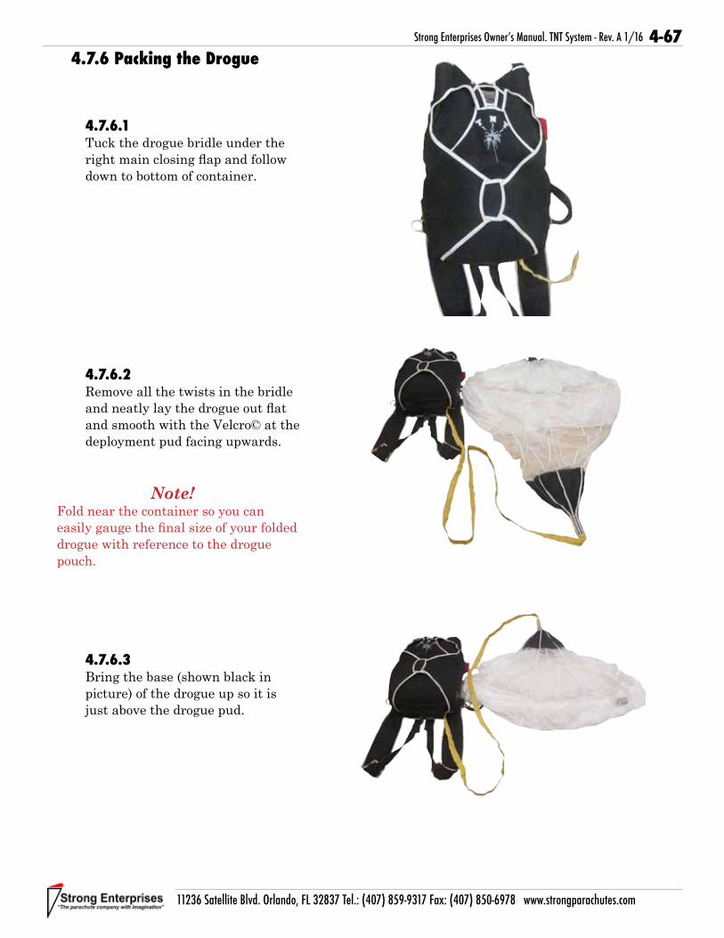
4-67
11236 Satellite Blvd. Orlando, FL 32837 Tel.: (407) 859-9317 Fax: (407) 850-6978 www.strongparachutes.com
Strong Enterprises Owner’s Manual. TNT System - Rev. A 1/16
4.7.6 Packing the Drogue
4.7.6.1Tuck the drogue bridle under the right main closing flap and follow down to bottom of container.
4.7.6.2Remove all the twists in the bridle and neatly lay the drogue out flat and smooth with the Velcro© at the deployment pud facing upwards.
Note!
Fold near the container so you can easily gauge the final size of your folded drogue with reference to the drogue pouch.
4.7.6.3Bring the base (shown black in picture) of the drogue up so it is just above the drogue pud.

4-68
11236 Satellite Blvd. Orlando, FL 32837 Tel.: (407) 859-9317 Fax: (407) 850-6978 www.strongparachutes.com
Strong Enterprises Owner’s Manual. TNT System - Rev. A 1/16
4.7.6.4Next bring the drogue body up to the base. All the mesh should now be inside the folds of the drogue.
4.7.6.5Fold the base over the folded body exposing the drogue pud.
4.7.6.6Fold the bottom of the drogue where the base and bridle connect up over drogue base material.
4.7.6.7S-folds with the bridle on top of the base, leaving approximately 18”-24” of the bridle unfolded.
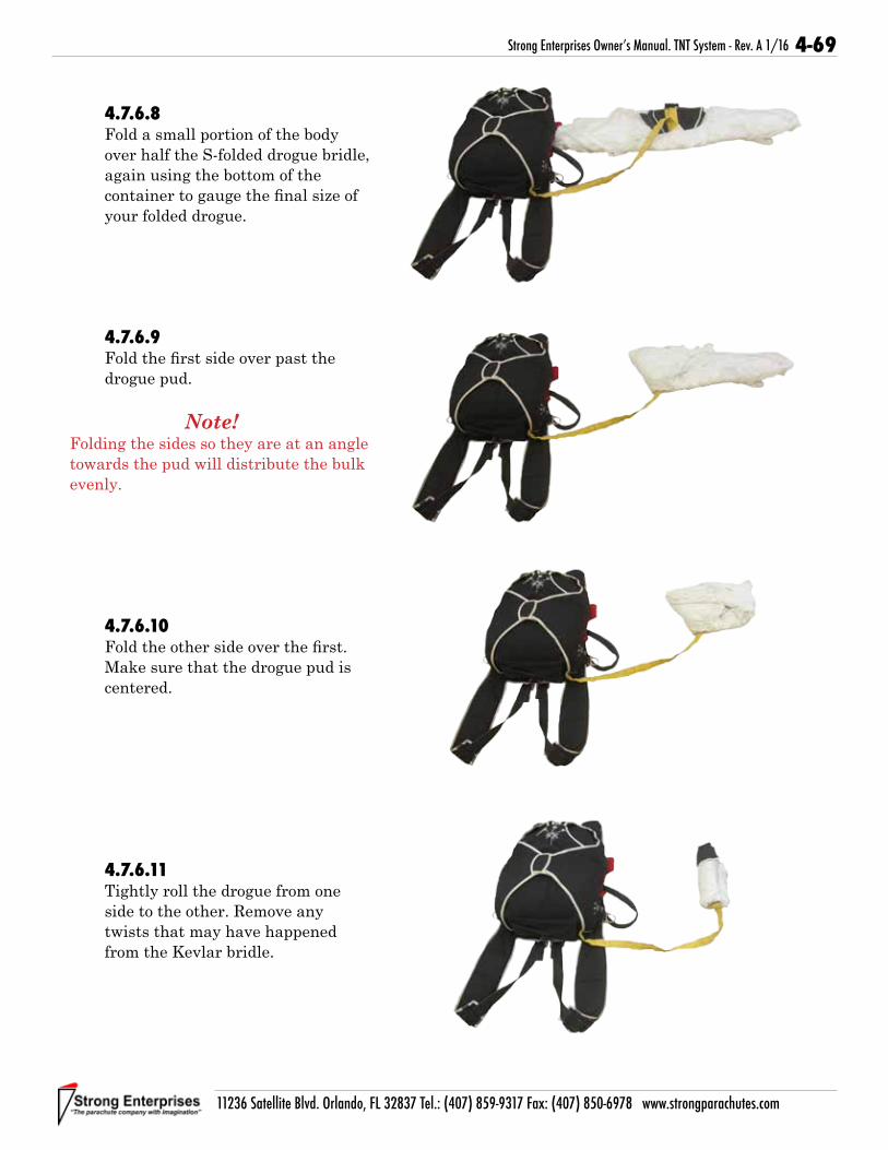
4-69
11236 Satellite Blvd. Orlando, FL 32837 Tel.: (407) 859-9317 Fax: (407) 850-6978 www.strongparachutes.com
Strong Enterprises Owner’s Manual. TNT System - Rev. A 1/16
4.7.6.8Fold a small portion of the body over half the S-folded drogue bridle, again using the bottom of the container to gauge the final size of your folded drogue.
4.7.6.9Fold the first side over past the drogue pud.
Note!
Folding the sides so they are at an angle towards the pud will distribute the bulk evenly.
4.7.6.10Fold the other side over the first. Make sure that the drogue pud is centered.
4.7.6.11Tightly roll the drogue from one side to the other. Remove any twists that may have happened from the Kevlar bridle.

4-70
11236 Satellite Blvd. Orlando, FL 32837 Tel.: (407) 859-9317 Fax: (407) 850-6978 www.strongparachutes.com
Strong Enterprises Owner’s Manual. TNT System - Rev. A 1/16
4.7.6.12Stow the excess drogue bridle in the drogue pouch.
4.7.6.13Stow the drogue in the pouch so that the drogue pud remains outside the pouch.
4.7.6.14Mate the Velcro on the drogue pud to the container.

4-71
11236 Satellite Blvd. Orlando, FL 32837 Tel.: (407) 859-9317 Fax: (407) 850-6978 www.strongparachutes.com
Strong Enterprises Owner’s Manual. TNT System - Rev. A 1/16
Notes:

4-72
11236 Satellite Blvd. Orlando, FL 32837 Tel.: (407) 859-9317 Fax: (407) 850-6978 www.strongparachutes.com
Strong Enterprises Owner’s Manual. TNT System - Rev. A 1/16
Notes:

5-1
11236 Satellite Blvd. Orlando, FL 32837 Tel.: (407) 859-9317 Fax: (407) 850-6978 www.strongparachutes.com
Strong Enterprises Owner’s Manual. TNT System - Rev. A 1/16
Section Five:
Appendices

5-2
11236 Satellite Blvd. Orlando, FL 32837 Tel.: (407) 859-9317 Fax: (407) 850-6978 www.strongparachutes.com
Strong Enterprises Owner’s Manual. TNT System - Rev. A 1/16
Appendix A - Line Charts A-1 General Line Installation SET-400 and SET-366 Main Canopy
Color Codes on suspension lines:
A - Green
B - Blue
C - Black
D - Red
Suspension Lines
Insert B/D line at insertion mark.Line up with mark on A/C line.Pull line out approximately 4.5” down.Ziz-zag, double-throw (308)Pull out end of line and cut off in a 45 degree angle at cut-off mark.
A & C Lines B & D Lines
Insertion Mark
Cut-off Mark4” (100mm) between marks
Insertion Mark
Control Lines E1 and E2 (two uppers)
4” (100mm) between marksInsertion Mark
Cut-off Mark
Always trim end of line at 45 degree angle.
Note!
Do not hot knife.Use Scissors.

5-3
11236 Satellite Blvd. Orlando, FL 32837 Tel.: (407) 859-9317 Fax: (407) 850-6978 www.strongparachutes.com
Strong Enterprises Owner’s Manual. TNT System - Rev. A 1/16
A-2 SET-400 Main Canopy Outer Line Length Ribs 1,2,3,8,9,10
Measurements are installed on canopy with brakes set.
A B C D
D Total 79.50
A Total195.50
C Total208.00
B Total 83.25

5-4
11236 Satellite Blvd. Orlando, FL 32837 Tel.: (407) 859-9317 Fax: (407) 850-6978 www.strongparachutes.com
Strong Enterprises Owner’s Manual. TNT System - Rev. A 1/16
A-3 SET-400 Main Canopy Inner Line Length
Ribs 4,5,6,7
Measurements are installed on canopy with brakes set.
A B C D
D Total 86.5
A Total195.5
B Total199.25
C Total209.25

5-5
11236 Satellite Blvd. Orlando, FL 32837 Tel.: (407) 859-9317 Fax: (407) 850-6978 www.strongparachutes.com
Strong Enterprises Owner’s Manual. TNT System - Rev. A 1/16
A-4 SET-400 Main Canopy Control Line Attachment
Denotes Structural Rib
Denotes Soft Rib
Control LinesSpectra: P/N 865013HMA: P/N 865014
TotalE1 + F1 + G
233.50
Total Inner Line
242.50
93.5
22.0
211.5
73.597.5

5-6
11236 Satellite Blvd. Orlando, FL 32837 Tel.: (407) 859-9317 Fax: (407) 850-6978 www.strongparachutes.com
Strong Enterprises Owner’s Manual. TNT System - Rev. A 1/16
A-5 SET-400 Line Dimensions

5-7
11236 Satellite Blvd. Orlando, FL 32837 Tel.: (407) 859-9317 Fax: (407) 850-6978 www.strongparachutes.com
Strong Enterprises Owner’s Manual. TNT System - Rev. A 1/16
A-6 SET-366 Main Canopy Outer Line Length Ribs 1,2,3,8,9,10
Measurements are installed on canopy with brakes set.
A B C D
D Total 75 1/2
A Total185 3/8
C Total197 3/8
B Total 79 1/8

5-8
11236 Satellite Blvd. Orlando, FL 32837 Tel.: (407) 859-9317 Fax: (407) 850-6978 www.strongparachutes.com
Strong Enterprises Owner’s Manual. TNT System - Rev. A 1/16
A B C D
82
A Total185 5/8
B Total189 1/2
C Total198 1/8
A-7 SET-366 Main Canopy Inner Line Length
Ribs 4,5,6,7
Measurements are installed on canopy with brakes set.

5-9
11236 Satellite Blvd. Orlando, FL 32837 Tel.: (407) 859-9317 Fax: (407) 850-6978 www.strongparachutes.com
Strong Enterprises Owner’s Manual. TNT System - Rev. A 1/16
A-8 SET-366 Main Canopy Control Line Attachment
Denotes Structural Rib
Denotes Soft Rib
Control LinesSpectra: P/N 865357HMA: P/N 865361
TotalE1 + F1 + G
222 7/8
Total Inner Line
230 5/8
88 1/2
21 3/8
201 1/2
70 1/492 1/2

5-10
11236 Satellite Blvd. Orlando, FL 32837 Tel.: (407) 859-9317 Fax: (407) 850-6978 www.strongparachutes.com
Strong Enterprises Owner’s Manual. TNT System - Rev. A 1/16
A-9 SET-366 Line Dimensions

5-11
11236 Satellite Blvd. Orlando, FL 32837 Tel.: (407) 859-9317 Fax: (407) 850-6978 www.strongparachutes.com
Strong Enterprises Owner’s Manual. TNT System - Rev. A 1/16
Appendix B: TSO Letter for TNT, Patronus Reserve, Air Anchor

5-12
11236 Satellite Blvd. Orlando, FL 32837 Tel.: (407) 859-9317 Fax: (407) 850-6978 www.strongparachutes.com
Strong Enterprises Owner’s Manual. TNT System - Rev. A 1/16

5-13
11236 Satellite Blvd. Orlando, FL 32837 Tel.: (407) 859-9317 Fax: (407) 850-6978 www.strongparachutes.com
Strong Enterprises Owner’s Manual. TNT System - Rev. A 1/16
A total of 48 Drop tests were conducted at various weights and speeds. For each of the weights and speeds below four total drops were done, two with the main in the container and two without the main. Each number represents the average opening time measured from pin pull to slider being down.
Test Weight 60 KEAS 85 KEAS 140 KEAS 175 KEAS200 lbs (+2/-20) 5.9 5.7 5.8 5.3350 lbs (+/- 17) 5.0 5.9 5.1 4.9500 lbs (+50/-5) 5.5 4.4 3.9 4.2
A total of 26 Live jumps were conducted. There were 6 direct reserve deployments. Two were with a delay of less than 3 seconds, and four were with a delay of more than 20 seconds. The average opening time for the direct reserve deployments was 5.1 seconds. Next we conducted cutaway tests. Eight were from a stable main canopy, four from a forward spinning main canopy, four from a backwards spinning main canopy, and finally four from a baglocked main canopy. The average opening times measured from pin pull to slider being down are listed below.
Stable Main 5.9
Forward Spin 5.6Backward Spin 5.7Bag Lock 4.7
Appendix C: TSO Drop Test Results

5-14
11236 Satellite Blvd. Orlando, FL 32837 Tel.: (407) 859-9317 Fax: (407) 850-6978 www.strongparachutes.com
Strong Enterprises Owner’s Manual. TNT System - Rev. A 1/16
Notes:

5-15
11236 Satellite Blvd. Orlando, FL 32837 Tel.: (407) 859-9317 Fax: (407) 850-6978 www.strongparachutes.com
Strong Enterprises Owner’s Manual. TNT System - Rev. A 1/16
Appendix D: TNT Inspection Check ListUse this check-list to ensure all steps of the Maintenance Check are completed.
Harness/Container SN__________ Date of Manufacture__________ In Service Date__________________
Refer to Maintenance Inspection:
Date Date Date Date Harnesses (Instructor and Student) Page Section
No rust on hardware 3-5 3.3.3.1
Proper hardware installed. 3-5 3.3.3.1
Springs on snaps still functional. 3-5 3.3.3.1
4-point stitching on instructor side O-Ring attachments secure with no broken stitches.
3-5 3.3.3.1
Hardware functional and tacked (leg strap Quick Ejectors). 3-5 3.3.3.1
No cuts on webbing. 3-5 3.3.3.1
Stitching is not unraveling on webbing. 3-5 3.3.3.1
No excessive fading of webbing. 3-5 3.3.3.1
Date Date Date Date Container Page Section
No rough edges, dents, or bends in grommets. 3-5 3.3.3.1
Grommets secure and in place. 3-5 3.3.3.1
Grommet fingernail test complete. 3-5 3.3.3.1
Drogue riser “L” link screws tight. 3-5 3.3.3.1
Closing pin housing on drogue riser securely tacked. 3-5 3.3.3.1
No cuts or frays in drogue riser webbing. 3-5 3.3.3.1
Closing flap and tuck tab stiffeners in good condition. 3-5 3.3.3.1
No holes or tears in Cordura or binding. 3-5 3.3.3.1
No broken stitches in Cordura or binding. 3-5 3.3.3.1
Drogue pouch secure. 3-5 3.3.3.1
No holes in drogue pouch. 3-5 3.3.3.1
Opening securely holds Drogue. 3-5 3.3.3.1
All Velcro© locations are clean. 3-5 3.3.3.1
Velcro© is secure and in place. 3-5 3.3.3.1
Date Date Date Date Ripcords, Drogue Release Cables and Housings Page Section
No excessive wear of ripcord hardware. 3-6 3.3.3.2
No kinks, frays, or broken strands in ripcord cables. 3-6 3.3.3.2
Cable tip is not exposed. 3-6 3.3.3.2
Reserve Pin straight. 3-6 3.3.3.2
Swedge’s are secure and approved parts. 3-6 3.3.3.2
Red H.G. line on 3-ring release not frayed or cut. 3-6 3.3.3.2
Rings on 3-ring release secure. 3-6 3.3.3.2
No dents, cracks, or rough edges on rings. 3-6 3.3.3.2
No prominent curves in 3-ring release cable. 3-6 3.3.3.2
Housings complete, no broken or missing housing caps. 3-6 3.3.3.2
Cable housings free of all dirt, gravel, sand, debris and are lubricated. 3-6 3.3.3.2

5-16
11236 Satellite Blvd. Orlando, FL 32837 Tel.: (407) 859-9317 Fax: (407) 850-6978 www.strongparachutes.com
Strong Enterprises Owner’s Manual. TNT System - Rev. A 1/16
Main Canopy SN___________ Date of Manufacture________ In Service Date________________
Refer to Maintenance Inspection:
Date Date Date Date Main Canopy Page Section
Like line group deviation within 1-inch. 3-6 3.3.3.3
No excessive wear in lines. 3-6 3.3.3.3
No loose stitching at link, cascade, and canopy attachment bartacks. 3-6 3.3.3.3
Rear riser cable housings secure. 3-6 3.3.3.3
Rear riser cable housing clean and free of debris. 3-6 3.3.3.3
No webbing wear at 3-ring attachment point. 3-6 3.3.3.3
Stitching on riser webbing unbroken. 3-6 3.3.3.3
Swedish link functional. 3-6 3.3.3.3
No cracks in Rapide Links. 3-6 3.3.3.3
No holes in slider, stitching good. 3-6 3.3.3.3
No burrs on slider grommets. 3-6 3.3.3.3
Slider grommets secure. 3-6 3.3.3.3
Grommets on slider do not spin. 3-6 3.3.3.3
Fingernail test on slider grommets complete. 3-6 3.3.3.3
Seam and line attachment stitch intact. 3-7 3.3.3.3
All panels free of damage. 3-7 3.3.3.3
No holes, tears, or burns in the fabric. 3-7 3.3.3.3
No excessive wear at bridle attachment point. 3-7 3.3.3.3
Date Date Date Date Drogue and Deployment Bag Page Section
No holes or tears in fabric. 3-7 3.3.3.4
Reinforcing tape on drogue body undamaged. 3-7 3.3.3.4
Stitching and zigzag at base of drogue canopy complete. 3-7 3.3.3.4
Drogue mesh free of holes and tears. 3-7 3.3.3.4
No loose or broken stitching in bridle. 3-7 3.3.3.4
No holes or excessive wear in the bridle. 3-7 3.3.3.4
Bridle attachment point not worn or frayed. 3-7 3.3.3.4
Bumper and Rapide Link not damaged and in correct place. 3-7 3.3.3.4
3-ring attachment complete and not bent or damaged. 3-7 3.3.3.4
Y-deflation line bartack not loose or fraying. 3-7 3.3.3.4
No excessive wear and no twists in the Y-deflation line. 3-7 3.3.3.4
Drogue flex pin smooth, no nicks in coating, no broken strands in cable. 3-7 3.3.3.4
Shock cord loops not broken or frayed, and not stretched out longer than 3 inches.
3-7 3.3.3.4
Rubber bands in place and in good condition. 3-7 3.3.3.4
Deployment bag grommets secure. 3-7 3.3.3.4
Velcro secure and in good condition. 3-7 3.3.3.4

5-17
11236 Satellite Blvd. Orlando, FL 32837 Tel.: (407) 859-9317 Fax: (407) 850-6978 www.strongparachutes.com
Strong Enterprises Owner’s Manual. TNT System - Rev. A 1/16
Notes:

5-18
11236 Satellite Blvd. Orlando, FL 32837 Tel.: (407) 859-9317 Fax: (407) 850-6978 www.strongparachutes.com
Strong Enterprises Owner’s Manual. TNT System - Rev. A 1/16
PROUDLY MADE IN THE U.S.A
Pho
tos
by
Phil
Rob
erso
n
Pho
tos
of T
om
No
on
an a
nd
Dav
e B
azzo
ni
• The most predictable and reliable tandem
canopy available• Durability leader in the tandem industry
• Consistent and dependable openings• Smooth and responsive flight characteristics • Exceptional penetration ability and flat glideThe SET-400 is a high performance, semi-elliptical 9-cell main canopy. Setting the bar for Tandem Flight since 1995.
• The SET-366 is a high performance, semi-elliptical, 9 cell main canopy
• It provides soft, on heading openings com-
bined with an increase in flight perfor-
mance
• Toggle pressure has been dramatically reduced on the SET-366, making turns and flaring light and easy
You can spend all day long flying the SET-366 over and over again, and land your last jump of the day as smoothly as your first.
NEW Risers with Every Canopy!