tnc female bulkhead mount connector crimp/solder ...€¦ · pe-b100, pe-c100 and .100 inch (.480...
TRANSCRIPT

1
Configuration• TNC Female Connector• MIL-STD-348A• 50 Ohms• Straight Body Geometry
• RG174, RG316, RG188, LMR-100, PE-B100, PE-C100, .100 inch Interface Type
• Crimp/Solder Attachment• Bulkhead
Features• Max. Operating Frequency 1,000 MHz• Good VSWR of 1.5:1
• Gold Plated Brass Contact• 30 µin minimum contact plating
Applications• General Purpose Test • Rack and Panel Mount Applications • Custom Cable Assemblies
.
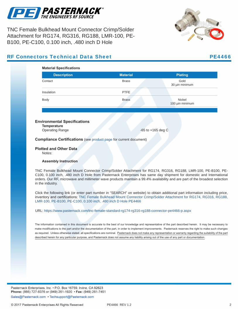
DescriptionPasternack’s PE4466 TNC female bulkhead connector with crimp/solder attachment for RG174, RG316, RG188, LMR-100, PE-B100, PE-C100 and .100 inch (.480 inch D hole) is part of our full line of RF components available for same-day shipping. Our TNC female connector operates up to a maximum frequency of 1,000 MHz and offers good VSWR of 1.5:1. This TNC bulkhead connector allows designers to create external connections on their product enclosures, and can be used in a variety of other rack mount and panel mount applications.
Our TNC female bulkhead connector PE4466 datasheet specifications and drawing with dimensions are shown below in this PDF. Pasternack’s broad catalog of RF, microwave and millimeter wave connectors allows designers to configure and customize their signal connections however they like. Whether the need is to provide an I/O for a board design, or simply create a custom cable assembly configuration, Pasternack has the right connector for the job. Pasternack can also expertly build your custom cable assemblies for you and ship same-day.
Electrical Specifications
Description Minimum Typical Maximum Units Frequency Range DC 1,000 MHz VSWR 1.5:1 Operating Voltage (AC) 500 Vrms .
Mechanical Specifications
SizeLength 1.425 in [36.2 mm]Width/Dia. 0.689 in [17.50 mm] .
Weight 0.045 lbs [20.41 g].
Click the following link (or enter part number in “SEARCH” on website) to obtain additional part information including price, inventory and certifications: TNC Female Bulkhead Mount Connector Crimp/Solder Attachment for RG174, RG316, RG188, LMR-100, PE-B100, PE-C100, 0.100 inch, .480 inch D Hole PE4466
PE4466 REV 1.2
TNC Female Bulkhead Mount Connector Crimp/Solder Attachment for RG174, RG316, RG188, LMR-100, PE-B100, PE-C100, 0.100 inch, .480 inch D Hole
RF Connectors Technical Data Sheet PE4466
2
Material Specifications
Description Material Plating Contact Brass Gold 30 µin minimum
Insulation PTFE
Body Brass Nickel 100 µin minimum
.
Environmental SpecificationsTemperatureOperating Range -65 to +165 deg C
Compliance Certifications (see product page for current document)
Plotted and Other DataNotes:
Assembly Instruction
TNC Female Bulkhead Mount Connector Crimp/Solder Attachment for RG174, RG316, RG188, LMR-100, PE-B100, PE-C100, 0.100 inch, .480 inch D Hole from Pasternack Enterprises has same day shipment for domestic and International orders. Our RF, microwave and millimeter wave products maintain a 99.4% availability and are part of the broadest selection in the industry.
Click the following link (or enter part number in “SEARCH” on website) to obtain additional part information including price, inventory and certifications: TNC Female Bulkhead Mount Connector Crimp/Solder Attachment for RG174, RG316, RG188, LMR-100, PE-B100, PE-C100, 0.100 inch, .480 inch D Hole PE4466
URL: https://www.pasternack.com/tnc-female-standard-rg174-rg316-rg188-connector-pe4466-p.aspx
PE4466 REV 1.2
RF Connectors Technical Data Sheet PE4466
TNC Female Bulkhead Mount Connector Crimp/Solder Attachment for RG174, RG316, RG188, LMR-100, PE-B100, PE-C100, 0.100 inch, .480 inch D Hole

3PE4466 REV 1.2
TNC Female Bulkhead Mount Connector Crimp/Solder Attachment for RG174, RG316, RG188, LMR-100, PE-B100, PE-C100, 0.100 inch, .480 inch D Hole
PE4466 CAD Drawing
1
Configuration• Snap-On MMBX Plug Connector• 50 Ohms• Right Angle Body Geometry
• RG316, RG174 Interface Type• Crimp/Solder Attachment
Features• Max. Operating Frequency 3 GHz • Excellent VSWR of 1.17:1 • Gold Plated Beryllium Copper Contact • Blind Mate Connector
• Reliable Snap-On connection method• Small circuit footprint for high density applications• Mechanical misalignment tolerance of 4.5°/0.7mm Max
Applications• General Purpose Test • Custom Cable Assemblies • Low cost blind mate interconnect
• Multi circuit board radios • Board to board applications requiring multiple coaxial connections
.
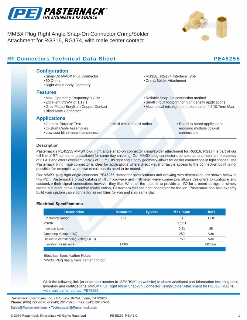
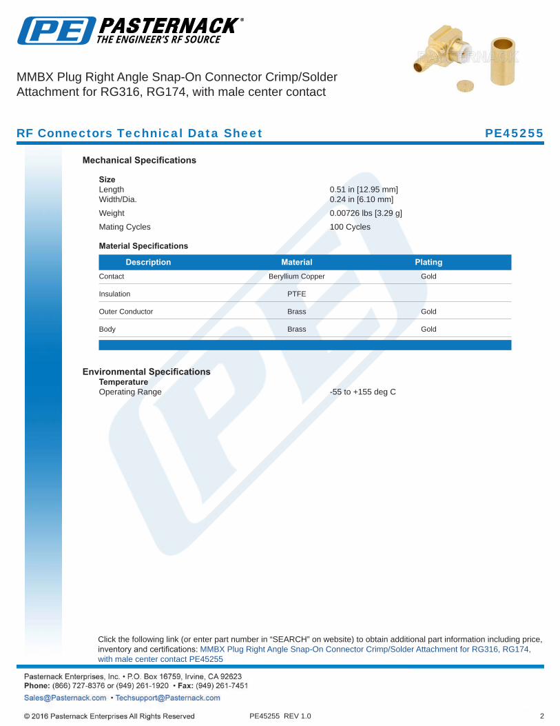
DescriptionPasternack’s PE45255 MMBX plug right angle snap-on connector crimp/solder attachment for RG316, RG174 is part of our full line of RF components available for same-day shipping. Our MMBX plug connector operates up to a maximum frequency of 3 GHz and offers excellent VSWR of 1.17:1. Its right angle body geometry allows for easier connections in tight spaces. The Pasternack blind mate connector is ideal for applications where direct visual or tactile access to the connection point is not possible, for example, when two circuit boards need to be mated.
Our MMBX plug right angle connector PE45255 datasheet specifications and drawing with dimensions are shown below in this PDF. Pasternack’s broad catalog of RF, microwave and millimeter wave connectors allows designers to configure and customize their signal connections however they like. Whether the need is to provide an I/O for a board design, or simply create a custom cable assembly configuration, Pasternack has the right connector for the job. Pasternack can also expertly build your custom cable connector assemblies for you and ship same-day.
Electrical Specifications
Description Minimum Typical Maximum Units Frequency Range DC 3 GHz VSWR 1.17:1 Insertion Loss 0.31 dB Operating Voltage (DC) 250 Vdc Dielectric Withstanding Voltage (DC) 750 Vdc Insulation Resistance 1,000 MOhms .
Electrical Specification Notes: MMBX Plug has a male center contact
Click the following link (or enter part number in “SEARCH” on website) to obtain additional part information including price, inventory and certifications: MMBX Plug Right Angle Snap-On Connector Crimp/Solder Attachment for RG316, RG174, with male center contact PE45255
PE45255 REV 1.0
MMBX Plug Right Angle Snap-On Connector Crimp/Solder Attachment for RG316, RG174, with male center contact
RF Connectors Technical Data Sheet PE45255
2
Mechanical Specifications
SizeLength 0.51 in [12.95 mm]Width/Dia. 0.24 in [6.10 mm] .
Weight 0.00726 lbs [3.29 g].
Mating Cycles 100 Cycles
Material Specifications
Description Material Plating Contact Beryllium Copper Gold
Insulation PTFE
Outer Conductor Brass Gold
Body Brass Gold
.
Environmental SpecificationsTemperatureOperating Range -55 to +155 deg C
PE45255 REV 1.0
Click the following link (or enter part number in “SEARCH” on website) to obtain additional part information including price, inventory and certifications: MMBX Plug Right Angle Snap-On Connector Crimp/Solder Attachment for RG316, RG174, with male center contact PE45255
RF Connectors Technical Data Sheet PE45255
MMBX Plug Right Angle Snap-On Connector Crimp/Solder Attachment for RG316, RG174, with male center contact

3
Compliance Certifications (see product page for current document)
Plotted and Other DataNotes:
MMBX Plug Right Angle Snap-On Connector Crimp/Solder Attachment for RG316, RG174, with male center contact from Pasternack Enterprises has same day shipment for domestic and International orders. Our RF, microwave and millimeter wave products maintain a 99% availability and are part of the broadest selection in the industry.
Click the following link (or enter part number in “SEARCH” on website) to obtain additional part information including price, inventory and certifications: MMBX Plug Right Angle Snap-On Connector Crimp/Solder Attachment for RG316, RG174, with male center contact PE45255
URL: https://www.pasternack.com/mmbx-plug-snap-on-rg316-rg174-connector-pe45255-p.aspx
PE45255 REV 1.0
RF Connectors Technical Data Sheet PE45255
MMBX Plug Right Angle Snap-On Connector Crimp/Solder Attachment for RG316, RG174, with male center contact

4PE45255 REV 1.0
MMBX Plug Right Angle Snap-On Connector Crimp/Solder Attachment for RG316, RG174, with male center contact
PE45255 CAD Drawing

(800) TMS-COAX • www.timesmicrowave.com8
TIMES MICROWAVE SYSTEMS
LMR®-100A Flexible Low Loss Communications Coax
LMR
-100
A
Ideal for… •Drop-inReplacementforRG-316/RG-174(usesstandardconnectors) •JumperAssembliesinWirelessCommunicationsSystems •ShortAntennaFeederruns •Anyapplication(e.g.WLL,GPS,LMR,WLAN,WISP,WiMax, SCADA,MobileAntennas)requiringaneasilyrouted, lowlossRFcable
Mechanical Specifications Performance Property Units US (metric)
Bend Radius: installation in. (mm) 0.25 (6.4) Bend Radius: repeated in. (mm) 1 (25.4) Bending Moment ft-lb (N-m) 0.1 (0.014) Weight lb/ft (kg/m) 0.0092 (.014) Tensile Strength lb (kg) 15 (6.8) Flat Plate Crush lb/in. (kg/mm) 10 (0.18)
Electrical Specifications Performance Property Units US (metric)
Velocity of Propagation % 66 Dielectric Constant NA 2.30 Time Delay nS/ft (nS/m) 1.54 (5.05) Impedance ohms 50 Capacitance pF/ft (pF/m) 30.8 (101.1) Inductance uH/ft (uH/m) 0.077 (0.25) Shielding Effectiveness dB >90 DC Resistance Inner Conductor ohms/1000ft (/km) 81.0 (266) Outer Conductor ohms/1000ft (/km) 9.5 (31.2) Voltage Withstand Volts DC 500 Jacket Spark Volts RMS 2000 Peak Power kW 0.6
• LMR®- PVC isdesignedforlowlossgeneral-purposeindoor/outdoorapplicationsandissomewhatmoreflexiblethanthestandardpolyethylenejacketedLMR.• LMR®- PVC-W isawhite-jacketedversionofLMR-PVCformarineandotherindoor/outdoorapplicationswherecolorcompatibilityisdesired.•FlexibilityandbendabilityarehallmarksoftheLMR-100Acabledesign.Theflexibleouterconductorenablesthetightestbendradiusavailableforanycableofsimilarsizeandperformance.• Low Loss isanotherhallmarkfeatureofLMR-100A.SizeforsizeLMRhasthelowestlossofanyflexiblecableandcomparablelosstosemirigidhard-linecables.• RF Shielding is50dBgreaterthantypicalsingleshieldedcoax(40dB).Themulti-plybondedfoilouterconductorisratedconservativelyat>90dB(i.e.>180dBbetweentwoadjacentcables).•Weatherability:LMR-100Acables designed foroutdoorexposureincorporatethebestmaterialsforUVresistanceandhavelifeexpectancyinexcessof20years.• Connectors:AwidevarietyofconnectorsareavailableforLMR-100Acable,includingallcommoninterfacetypes,reversepolarity,andachoiceofsolderornon-soldercenterpins.MostLMRconnectorsemploycrimpouterattachmentusingstandardhexcrimpsizes.• Cable Assemblies:AllLMR-100Acabletypesareavailableaspre-terminatedcableassemblies.RefertothesectiononFlexTechforfurtherdetails.
Environmental Specifications Performance Property 0F oC
Installation Temperature Range -40/+185 -40/+85 Storage Temperature Range -94/+185 -70/+85 Operating Temperature Range -40/+185 -40/+85
Part Description Stock
Part Number Application Jacket Color Code
LMR-100A-FR Indoor/Outdoor Riser CMR FRPE Black 54037
LMR-100A-PVC Indoor/Outdoor PVC Black 54119LMR-100A-PVC-W Indoor/Outdoor PVC White 54200
PVC = Poly Vinyl Chloride; MTO = Made to Order
Construction Specifications Description Material In. (mm)
Inner Conductor Solid BCCS 0.018 (0.46) Dielectric Solid PE 0.060 (1.52) Outer Conductor Aluminum Tape 0.065 (1.65) Overall Braid Tinned Copper 0.083 (2.11) Jacket (see table above) 0.110 (2.79)

(800) TMS-COAX • www.timesmicrowave.com 9
TIMES MICROWAVE SYSTEMS
LMR
-100
A
Attenuation vs. Frequency (typical)
Att
enu
atio
n(d
b pe
r 100
feet
)100
10
110 100 1,000 10,000
Calculate Attenuation = (0.709140) • FMHz + (0.001740) • FMHz (interactive calculator available at http://www.timesmicrowave/telecom)Attenuation: VSWR=1.0 ; Ambient = +25°C (77°F) Power: VSWR=1.0; Ambient = +40°C; Inner Conductor = 100°C (212°F);
Sea Level; dry air; atmospheric pressure; no solar loading
Frequency (MHz) 30 50 150 220 450 900 1500 1800 2000 2500 5800 Attenuation dB/100 ft 3.9 5.1 8.9 10.9 15.8 22.8 30.1 33.2 35.2 39.8 64.1 Attenuation dB/100 m 12.9 16.7 29.4 35.8 51.9 74.9 98.7 109.0 115.5 130.6 210.3 Avg. Power kW 0.230 0.180 0.100 0.083 0.057 0.039 0.029 0.027 0.025 0.022 0.013
Frequency (MHz)
CCT-01
TC-100-SM TC-100-TM
Connectors Inner Outer Finish* Part Stock VSWR ** Coupling Contact Contact Body Length Width Weight Interface Description Number Code Freq. (GHz) Nut Attach Attach /Pin in (mm) in (mm) lb (g)
SMA male Straight Plug TC-100-SM 3190-1551 <1.25:1 (<3 ) Hex Solder Crimp SS/G 1.0 (25.4) 0.32 (8.1) 0.015 (6.8)
TNC male Straight Plug TC-100-TM 3190-1552 <1.25:1 (<3 ) Knurl Solder Crimp S/G 1.4 (35.6) 0.59 (15.0) 0.045 (20.4)
* Finish metals: N=Nickel, S=Silver, G=Gold, SS=Stainless Steel, A=Alballoy **VSWR spec based on 3 foot cable with a connector pair
CT-240/200/195/100 Install Tools Type Part Number Stock Code Description Crimp Tool CT-240/200/195/100 3190-667 Crimp tool for LMR-100, 195, 200 and 240 connectors Cutting Tool CCT-01 3190-1544 Cable end flush cut tool Replacement Blade RB-01 3190-1609 Replacement blade for cutting tool