tn associates, inc. standard operating procedure no. …
TRANSCRIPT

o
0'·············'" ,,'
Standard Operating Procedures' - Well and Borehole Abandonment
TN &ASSOCIATES, INC.STANDARD OPERATING PROCEDURE NO. IA6
WELL AND BOREHOLE ABANDONMENT
TABLE OF CONTENTSPage
1.0 ABANDONMENT 21.1 Introduction 21.2 Boreholes 2
1.2.1 Objective : 21.2.2 Procedure 2
1.3 Monitoring Wells ; 31.3.1 Objective ~ 31.3.2 Procedure : : ~ 3
1.3.2.1 Boreholes : ; 31.3.2.2 Monitoring Well Abandonment Removing Casing 31.3.2.3 Monitoring Well Abandonment Leaving Casing .4
1.4 Documentation ; 41.5 References 5
SOP IA6 Borehole abandonment - 9/20/2001· Page 10f5

o
Standard Operating Procedures - Well and Borehole Abandonment
TN &ASSOCIATES, INC.STANDARD OPERATING PROCEDURE NO. lAG
WELL AND BOREHOLE ABANDONMENT
1.0 ABANDONMENT
1.1 Introduction
Unplugged or improperly abandoned wells pose a potential threat to groundwater quality,because they may serve as a conduit for surface pollutants to migrate into the subsurface, orallow mixing of groundwater through interconnecting isolated aquifers. The objective of thisStandard Operating Procedure (SOP) is to provide the general procedures for the proper - abandonment of boreholes and wells. The methods must comply with applicable federal, state,and local rules and regulations, and protect the groundwater resource from undue degradation.
When performing abandonment procedures, it is important to understand the objectives of theabandonment, which are as follows:
• Eliminate physical hazards• Prevent groundwater contamination• Conserve aquifer yield and hydrostatic head• Prevent intermixing of groundwater within separated aquifer systems
The following well abandonment procedures are based upon United States EnvironmentalProtection Agency (USEPA) Region N guidance (USEPA, 1996).
1.2 Boreholes
All boreholes will be backfilled with grout in accordance with site-specific'requirements. Thegrout emplacement and mixture procedures will comply with specifications provided in SOP No.1A7 with regard to monitoring well annular seals. Unless saturated conditions are encountered ora monitoring well is to be installed, the borehole will be backfilled as soon as practical aftersampling is completed or data collected. For boreholes in which saturated cOllditions areencountered, grouting will be delayed for 24 hours so that a stabilized water level measurementmay be obtained. After the measure, the borehole will be backfilled according to procedure.Boreholes left open overnight will be adequately covered to eliminate the potential for injury topersonnel, In addition, the surrounding dirt or drill cuttings will be mounded around theborehole and the borehole will be covered with plastic sheeting to prevent surface drainage fromentering the borehole.
SOP 1A6 Borehole abandonment - 9/20/2001 Page 2 of5·
Standard Operating Procedures - Well and Borehole Abandonment
o 1.3 Monitoring Wells
Monitoring wells represent a more complex conduit for potential groundwater contamination andintermixing, because they consist of a rigid well pipe structure within an annulus that may befilled with different material along its vertical dimension. The preferred abandonment methodwill be to fill the well with grout from bottom to top. The abandonment procedure implemented .should be well documented and meet the abandonment objectives noted in Section 1.1. With thisin mind, it should be recognized that specific well abandonment methodologies will depend onseveral factors, including the following:
• Casing material, diameter, and condition• Quality of the original seal within the annulus• ' Total depth of the well• Well plumbness• Hydrogeologic conditions
.• Level of contamination and the zone(s) where the contamination occurs.
These factors should be considered when determining a specific abandonment procedure for aparticular well.
1.3.1 Objective
The purpose of this section is to provide procedures for the abandonment and plugging ofmonitoring wells..
1.3.2 Procedure
1.3.2.1 Boreholes
When a decision is made to abandon a monitoring well, the borehole will be sealed in such amanner that the well cannot act as a conduit for migration of contaminants from the groundsurface to the water table or between aquifers. To properly abandon a well, the preferred methodis to fill the well and porous annular space from the bottom of the structure to approximately2 feet bgs with a neat cement grout. The mixture of the grout will be in accordance with SOPNo. IA7. For all well abandonment procedures, the top two feet will be backfilled with concreteto insure a secure surface seal (plug). lfthe area exhibits heavy vehicular traffic and/or the welllocation(s) needs to be permanently marked, then a protective surface pad(s) and/or steel or PVCbumper guards will be installed. The concrete surface plug can also be recessed below groundsurface if the potential for construction activity exists.
A licensed water well contractor will conducted all well abandonment activities. This contractorwill be responsible for managing the well abandonment permitting process. The water wellcontractor will plug any well drilled under his license that is not completed or is not suitable forits intended use when work is completed. A well that is determined to be unsuitable for itsintended use will be properly abandoned within 14 days of notification.
1.3.2.2 Monitoring Well Abandonment Removing Casing
In some cases, other well abandonment procedures may be more effective in accomplishing theobjectives of preventing cross-contamination and intermixing of groundwater. One of thesemethods is to completely remove the well casing and screen from the borehole. This may be
SOP lA6 Borehole abandonment - 9/20/2001 Page 3 of5

Standm'd Operating Procedures - Well and Borehole Abandonment
o accomplished by over-drilling the well (for instance with hollow stem augers) over the wellcasing down to the bottom of the borehole, thereby removing the grout and filter pack materialsfrom the hole. The well casing will then be removed from the hole with the drill rig. The cleanborehole will then be tremie-grouted from bottom to top, as specified in SOP No. IA7 regarding
.annular well seals. The grout material will be placed into the borehole by pressure grouting withthe positive displacement method (tremie method). The ground surface completion of theabandoned well will comply with the specifications presented in the previous paragraph.
This abandonment method can be accomplished on small diameter (I-inch to 4-inch) wellswithout too much difficulty. With wells having 6-inch or larger diameters, the use of hollowstem augers for casing removal is very difficult, or almost impossible. Instead of trying to reamthe borehole with a hollow stem auger, it may be more practical to force a drill stem with atapered wedge assembly or a solid stem auger into the well casing and extract it out of the .borehole. Wells with little or no grouted annular space can be removed in this manner.
1.3.2.3 Monitoring Well Abandonment Leaving Casing
However, wells with badly corroded casings and/or thickly grouted annular space have atendency to twist and/or break-off in the borehole. When this occurs, the well will have to begrouted with the remaining casing left in the borehole. The preferred method in this case will beto pressure grout the borehole by placing the tremie tube at the bottom of the well casing, whichwill be the well screen or the bottom sump area below the well screen. The pressurized groutwill be forced out through the well screen into the filter material and up the inside of the wellcasing sealing holes and breaks that are present. The tremie tube will be retracted slowly as thegrout fills the casing to within two feet of the surface. The well casing will be cut off even withthe ground surface and filled with concrete from a depth of 2 feet to the surface. If the casing hasbeen broken off below the surface, the grout will be tremied to within 2 feet of the surface andthen finished to the ground surface with concrete.
Well casings consisting of PVC material may be more difficult to remove from the borehole thanmetal casings because of the brittleness of PVc. If the PVC well casing breaks during removal,the borehole will be cleaned out by using a drag bit or roller cone bit with a rotary drill method togrind the casing into small cuttings that will be flushed out of the borehole by the selecteddrilling fluid. Another method is to use a solid-stem auger with a carbide auger head to grind thePVC casing into small cuttings that will be brought to the surface on the rotating flights. Afterthe casing materials have been removed from the borehole, the borehole will be cleaned out andpressure grouted in accordance with SOP No. IA7. As previously stated, the borehole will befinished with a concrete surface plug and adequate surface protection, unless directed otherwise.
1.4 Documentation
,The rig geologist will be responsible for fully documenting the well abandonment procedure..The following items will be documented in the field log book and the well abandonment form:
• Name of property owner
• Address of owner or property
• Well location
SOP 1A6 Borehole abandonment - 9/20/2001 Page 4 0[5

Standard Operating Procedures - Well and Borehole Abandonment
o · Type of well installation method and date
• Type of well
• Construction of well, including total depth, diameter, depth of casing, type of well material,diameter of borehole, and material within annulus
• Depth to bedrock (if applicable)
• Depth to groundwater
.' Formation material and characteristics
• Materials and quantities used to fill well, annulus
• Description of well abandonment procedures including drilling and placement of grout
• Description of drilling equipment
• Description and placement of well abandonment material
• .Casing removed or filled in-place
• Drilling contractor
. An example of a well abandonment log is forth coming from the State of GeoFgia.
1.5. References. .
Aller, L. et aI., Handbook of Suggested Practices for theDesign and Installation of Ground- .water Monitoring Wells, EPA 600/4-89/034, 1989.
U.S. Environmental Protection Agency Region N, Environmental Investigations StandardOperating Procedures and Quality Assurance Manual, Environmental Services Division,May 1996.
SOP lA6 Borehole abandonment - 9/20/2001 Page 5 of5

Standard Operating Procedures - Subsurface Water Investigation
T N & ASSOCIATES, INC.STANDARD OPERATING PROCEDURE NO. IA7
SUBSURFACE WATER INVESTIGATION
TABLE OF CONTENTS
. Page1.0 SUBSURFACE WATER INVESTIGATION : 3
1.1 Introduction 31.2 Monitoring Well Installation 3
1.2.1 Objective 31.2.2 Procedures 3
1.2.2.1 Well Design Specifications .41.2.2.2 Borehole Completion 51.2.2.3 Well Construction : 61.2.2.4 Double-Cased Wells ' 71.2.2.5 Well Head Completion , 81.2.2.6 . Documentation and Recording 8'
1.3 Fluid Level Measurement and Recording 9. 1.3.1 Objectives 9
O. 1.3.2 Procedures 9 ,
«,~ 1.3.2.1 Fluid Level Measuring Reference Point : 91.3.2.2 Electrical Tape Method ~ l 01.3.2.3 Continuous Recording 10
·1.3.2.4 Interface Probe Methods .111.3.2.5 . Data Reporting 11
1.4 Well Development 121.4.1 Objective 121.4.2 Procedures 121.4.3 Criteria and Well Development Documentation : 14
1.5 Monitoring Well Sampling 151.5.1 Objective ~ 151.5.2 Procedures 15
1.5.2.1 Pre-Sampling Trip Preparation 161.5.2.2 Initial Activities 161.5.2.3 Well Purging 171.5.2.4 Sample Collection 191.5.2.5 . Labeling and Handling Requirements 191.5.2.6 Collection of Quality Control Samples 191.5.2.7 Field Equipment Cleaning Procedures 20 .1.5.2.8 Field Documentation Procedures 20
oSOP lA7 Subsurface Water Invest 9/20/2001 Page 1 of34

o
Standard Operating Procedures - Subswface Water Investigation
1.6 Hydraulic Testing Procedures and Equipment.. ; ~.20
1.6.1 Single-Well Aquifer (Slug) Testing 211.6.,1.1 Objectives ~ 21'1,6.1.2 Procedures · 21
1.6.2 Multiple Well Aquifer Pumping Tests ; 241.6.2.1 Objectives ; 24
c
1.6.2.2 Procedure 251.7 References 33
SOP IA7 Subsurface Water Invest 9/20/2001 Page 2 of 34

,0
··0
Standard Operating Procedures - Subsuiface Water Investigation
TN & ASSOCIATES, INC.STANDARD OPERATING PROCEDURE NO. IA7
1.0 'SUBSURFACE WATER INVESTIGATION·
1.1 Introduction
The objective of this standard operating procedure (SOP) is to describe procedural guidelines forthe design, installation, and construction of groundwater monitoring wells to be compieted inunconsolidated portions of water-bearing geologic materials. This document also providesprocedures for well development, groundwater sampling, and hydraulic testing. Site-specificprocedures will depend on project objectives, geologic conditions, and appropriate state and
.federal regulations and standards.
1.2 Monitoring Well Installation
1.2.1 Objective
It is the policy of the Team to design, install, and construct monitoring wells in a manner thatensures that all wells installed meet the criteria of being (1) adequately sealed to prevent surfacecontamination or cross contamination between aquifers; (2) capable of yielding high qualitygroundwater samples representative of true water quality; (3) adequately protected; and (4) incompliance with allapplicable state and federal regulations. The procedures set forth in thissection apply to all personnel who are responsible, both directly and indirectly, fordesign of·monitoring well systems, oversight of drilling and construction operations, and evaluation of thesuitability and reliability of monitoring wells and data and measurements obtained frommonitoring wells.
1.2.2 Procedures
Monitoring wells are installed primarily to provide information on the hydrogeology of a site andto determine the extent of migration of contaminants, if any. The state certified well driller or hisrepresentative must be present at the site during all drilling operations. All drilling personnelmust meet all applicable Occupational Safety and Health Administration (OSHA) requirements.The supervising geologist, engineer, or hydrogeologist must be fully knowledgeable andexperienced with state and federal requirements/regulations for groundwater monitoringprograms (e.g., 40 CFR Part 264 Subpart F and R.61-79.264 Subpart F Resource Conservationand Recovery Act [RCRA] requirements, and R.61-68 Water Classifications and Standards).
Site-specific work plans will specify drilling methods to be used and will present proposed welldesign and construction details. The drilling methods, well design, and well construction willadhere to the criteria and methodologies presented in this document. The proposed well designwill be based on existing subsurface and water fluctuation data from previo'usly installed wells atIAAAP. The design will present these data with the grain size of the filter pack and a discussionof the procedure to be used in the field for determining screen placement. All equipment, wellmaterials; and tools that will enter the borehole must be decontaminated before borehole entryand will remain clean until installed in the borehole. If needed, they will be steam cleaned again.Well materials that are cleaned and wrapped by the manufacturer do not need to be cleanedunless the factory wrap is damaged or the materials show signs of staining.
sop lA7 Subsurface Water Invest 9/20/2001 Page 3 of34

Standard Operating Procedures - SubsUlface Water Investigation
o 1.2.2.1 Well Design Specifications
Well screen materials for monitoring wells will be selected depending upon the known orsuspected chemical contaminants at the site, and so that the completed monitoring well providesdata that meet the project DQOs. Generally, the screen will be sized to retain over 90 percent'ofthe filter pack and constructed from either machine slotted PVC or stainless steel screenmaterials dependent ·on the particular contaminants that are being investigated at the site. Wellscreen materials will be of the same size and strength material as the well riser and will be a noncontaminating, continuous wrap design. No glues, adhesives, lead shot, or lead wool will beused to connect the riser sections or screen. No field slotted screens will be permitted (machinedin the field/not factory manufactured).
Filter PackFilter pack material will be clean, washed, well-rounded silica sand sized to perform as a filterbetween the formation material and the well screen. Proper documentation will be furnishedconcerning the composition, grain-size distribution, cleaning procedure, and chemical analysis.The filter pack gradation shall have a uniformity coefficient (Cu) of not more than 2.5 and shall
. be sized so that the slotted screen will retain 90 percent of the material. A grain size distributioncurve for the filter pack materials used at each site will be included with the submittal of well
. construction diagrams (selected filter pack gradations for existing monitoring wells will be takeninto account also).
If a pertinent grain-size distribution curve is available for a particular site or monitoring well,then the following procedure will be used to design a filter pack.
1. Multiply the D30 size (from the grain-size distribution graph) by a factor of four to nine. (Pack-Aquifer ratio). A factor of four is used if the formation is fine-grained and uniform(Cu is less than 3), six if it is coarse-grained and non-uniform, and up to nine if it is highlynon-uniform and contains silt. Head losses through filter packs increase as the Pack-Aquifer(P-A) ratios decrease. In order to design a fairly stable filter pack with a minimum head l6ss, .
. the D30 size will be multiplied by a factor of four.
2. Plot the point from step 1 on the 30 percent abscissa of a grain-size distribution graph and.draw a smooth curve with a uniformity coefficient of approximately 2.5.
3. Acurve for the permissible limits of the filter pack is drawn plus or minus 8 percent of thedesired curve with the Cu of less than 2.5. The appropriate-sized filter packcan then bechosen from the grain-size distribution curves of various filter packs.
4. Select the slot openings for the well screen that will retain 90 percent or more of the filterpacks.
This design will be based on the gradation of the finest aquifer materials anticipated to beaffected by the screened part of the monitoring wells (USEPA, 1996).
oSOP lA7 Subsurface Water Invest 9/20/2001 Page 4 of34

o
·0(······"', ,.'
Standard Operating Procedures - Subsurface Water Investigation
If no pertinent grain-size distributions curves are available, then 0.01 O-inch continuous wrappedscreen will be used with appropriate sized filter pack material in accordance with the followingtable adapted from ASTM D 5092-90 (ASTM, 1990).
Slot Sand Pack 1% Passing Effective 30% PassingSize of Screen No. Mesh Size (D-I), Size (D-IO), Size (D-30),
Openin2, mm (in.) Size Name(s) mm mm mm0.125 (0.005) 5 100 0.09 to 0.12 0.14 to 0.17 0.17toO.210.25 (0.010) 10 16 to 40 0.25 to 0.35 0.4 to 0.5 0.5 to 0.60.50 (0.020) 20 10 to 20 0.7 to 0.9 1.0 to 1.2 1.2 to 1.50.75 (0.030) 30 10 to 20 0.7 to 0.9 1.0 to 1.2 1.2 to 1.51.0 (0.040) 40 8 to 12 1.2 to 1.4 1.6 to 1.8 1.7 to 2.01.5 (0.060) 60 6 to 9 1.5 to 1.8 1.7 to 2.0 2.5 to 3.02.0 (0.080) 80 4 to 8 2.0 to 2.4 2.4 to 3.0 2.6t03.1
In addition to the primary filter pack installed along the screened interval of the monitoring well,a secondary filter pack consisting of finer material will be installed to prevent bentonite pelletsfrom commingling with the primary filter pack. This is discussed further in Section 1.4.2.3.
Well RiserWell riser (casing) will consist of PVC or stainless steel. PVC pipe will be new, threaded, flushjoint, and as a minimum, conform to the requirements of ASTM F 480-81/SDR 13.5 (Schedule40). PVC pipe will bear markings identifying the material as that specified and will carry theseal of the National Sanitation Foundation. Stainless steel pipe will consist of new, flush-jointedand threaded, type 304, corrosion resistant steel. Unless noted in the site-specific work plans,monitoring wells will be 2-inch inside diameter.
Bentonite SealThe bentonite seal will be composed of commercially manufactured sodium bentonite pellets,which do not exceed 0.25-inch diameter. Clean, potable water will be used to hydrate thebentonite, as discussed in Section 1.2.2.3.
Annular Seal. The cement grout will consist of a mixture of Portland cement (ASTM C 150) and water in the
proportion of approximately six to seven gallons of approved water per bag of cement (94pounds). In addition, 3 to 5 percent by weight of sodium bentoni,te powder will be added. Theminimum acceptable grout weight will be 14 pounds per gallon (lbs/gal). The cement groutweight will be determined using a mud balance.. Water may be added to the mix in smallamounts, at the discretion of the field geologist, to increase viscosity as necessary.
1.2.2.2 Borehole Completion
Procedures for the drilling and advancement of soil borings are presented inSOP No. IA4,Section 1.3. Drilling techniques employed must minimize disturbance of subsurface samples andmust not introduce contamination to the subsurface or allow contaminants, if any, in shallowhydrogeologic units to migrate to deeper units.
SOP lA7 Subsurface Water Invest 9/20/2001 Page 5 of34.·

o
Standard Operating Procedures - Subswface Water Investigation
• Prior to installation of the casing and screen, the lengths and diameters of all components(including the bottom plug or cap) will be measured and recorded on the casing/well screentally form. The casing riser and screen assembly will be installed round, plumb, and true toline.
• A bottom plug will be attached to the bottom of the screened section.
• The well screen will be connected to the riser sections of the casing assembly. For wellsintended to monitor the upper surficial aquifer near the water table, the well screen will beinstalled so as to straddle the free water surface, extending both above and below the watertable to accommodate seasonal or other variations in its elevation. In all cases, the top of thescreen will be located at least 2 feet below the base of the down-hole seal. Screen slot sizewill be 0.010 inches, or the appropriate size based on grain size distribution analyses andfilter pack design, as discussed above.
• For wells installed to depths exceeding 40 feet, centralizers will be placed at locations justbelow the screen, just above the location of the bentonite seal, and at 50-foot intervals alongthe riser casing. A minimum of 3 centralizers will be installed. Centralizers will not be usedif their installation prevents the placement of the annular materials.
• Well risers will extend at least 2.5 feet above the ground surface, unless well casings must becompleted at ground surface level as specified by the client or mandated by site conditionsand planned use of the well. If a flush finish completion is conducted, the placement ofannular materials will be done in such a way that the inside of the well casing is protected,i.e., the protective vault will be waterproof and strong enough to support anticipated loads.
• The primary filter pack will be placed in the annulus between the well material and boreholeusing a side discharge tremie pipe, starting with the tremie at the bottom of the borehole andworking the tremie upward as the filter pack is emplaced. If necessary potable water may beused to aid tremie installation. When using hollow stem augers, the augers will be raisedincrementally during the installation of the filter pack to prevent bridging. Note: the augersmust not be rotated during this or any of the following activities. Attempts will be made
.to keep the bottom of the augers below the top of the filter pack during installation. The levelof the top of the filter pack in the annulus will be verified by tag-line measurement during allphases of emplacement. The filter pack will extend at least two feet above the top of thescreen.. The volume of the installed filter pack will be compared with the annular volume toverify proper placement of the filter pack. This material accounting will be recorded in thefield book as will the volume of potable water used (if any).
• A bentonite seal, at least 3 to 5 feet thick, will be placed immediately above the filter pack.Pouring of the pellets is acceptable for boreholes less than 50 feet where the annular space islarge enough to limit the potential for bridging and to allow measurements to insure that the
SOP LA7 Subsurface Water Invest 9/20/2001 Page 60f34

•
0:·'········\"" .... ,'"
o
Standard Operating Procedures - Subswface Water Investigation
pellets have been placed at proper intervals. For depths greater than 50 feet, the bentonitepellets will be installed through a tremie pipe. The bentonite pellet seal will be hydratedeither by pouring water or utilizing the tremie pipe with approximately one gallon of clean,potable water per linear foot of bentonite, and allowed to hydrate a minimum of four hoursbefore grouting is commenced. If the bentonite seal is located above the water table,bentonitepellets will be installed in 6-inch lifts and each lift hydrated a minimum of 30minutes between lifts before proceeding. After the placement of the final lift, the bentoniteseal will be allowed to hydrate another two hours before grouting the remaining annulus. Thelevelofthe top of the bentonite seal will be verified by tag-line measurement prior to
.grouting. When using hollow stem augers, the bottom of the augers will be left in theborehole as close as possible above the bentonite seal.
For depths greater than 50 feet, the borehole is to be pressure-grouted using a sidedischargingtremie pipe that is maintained 3 feet above the bentonite seal and will be used toslowly emplace the cement/bentonite grout mixture. If the borehole is less than 50 feet deep,the grout can be placed using gravity feed. When using hollow stem augers, the augers willbe pulled incrementally during the grouting procedures to limit borehole collapse. Grout willbe pumped into the annulus through the tremie pipe until undiluted grout flows from theborehole at the ground surface. The grout will be allowed to cure for at least 24 hours priorto development. After 24 hours, the depth of the grout will be checked. Ifit has collapsedmore than 10 percent of the well depth, the well will be checked for soundness. The annuluswill be refilled with grout to the desired depth.
1.2.2.4 Double-Cased Wells
Secondary (outer) casings will be installed in the borehole when drilling a monitoring well thatwill be installed at depths below relatively impermeable (confining) layers or below depths ofknown contamination. The purpose of the surface casing is to prevent cross-contaminationbetween two aquifer zo'nes and/or, when flowing sands make it impossible to install a monitoringwell using conventional methods, to properly install the monitoring well to the desired depth.
A pilot borehole will be drilled and the surface casing installed to slightly below the known depth,of contamination or a minimum of 2 feet into the confining layer. The diameter of the surfacecasing will be sufficient to contain the inner casing and a 2-inch annular space. The material ofthe surface casing may vary (PVC or carbon steel), but it will be chemically inert and able towithstand potential chemical degradation and any forces exerted on the casing during itsinstallation and the monitoring well construction.
The outer casing will be grouted by the tremie method from the bottom to within 2 feet of theground surface. The grout will be pumped into the annular space between the outer casing andthe borehole wall. This will be accomplished by either placing the tremie tube in the annularspace and pumping the grout from the bottom of the borehole to the surface, or placing a groutshoe or plug inside the casing at the bottom of the borehole and pumping the grout through thebottom grout plug and up the annular space on the outside ofthe casing. If the outer casing is setinto very tight clay, both of the above methods may have to be used, because the clay usuallyforms a tight seal in the bottom and around the outside of the casing preventing grout fromflowing freely during grout injection. A minimum of 24 hours will be allowed for the grout sealto cure before attempting to drill through it. The grout mixture used to seal the outer annular
SOP IA7 Subsurface Water Invest 9/20/2001 Page 7 of34

::0",I:'."' •.".'·.:.'..
Standard Operating Procedures - Subswface Water investigation
, SOP LA 7 Subsurface Water Invest 912012001 Page 8 of34

Standard Operating Procedures - Subswface Water Investigation
o · Depth, elevation, and type of well casing.
• Installation date or dates, and name of the driller, drilling company, and the geologistinstalling the well
• All pertinent construction details of monitoring wells, such as depth to and description of allannular fill materials; gradation of filter packs; length, location (depth and elevation),
. diameter, slot size, material, and manufacturer of well casing and screen; position ofcentralizers; and location of any blank pipe or intermediate casing installed in the well.
• Description of surface completion, including protective steel casing, protective pipes, andconcrete surface seal.
• Surveyed coordinates and elevation of top of ground and top of well riser. The accuracy ofthe survey points will be in accordance with SOP No. IA8.
• A discussion of information to include in the boring logs is presented in SOP No. IA4. Alloriginal well record forms, field report forms, and geologist logs will be maintained in theproject file.
1.3 Fluid Level Measurement and Recording
1.3;1 Objectives
o
This section presents procedures and guidelines for measuring groundwater and free productlevels in monitoring wells. Consistent repeatable data will be obtained.
1.3.2 Procedures
Groundwater and product fluid levels are measured to determine the existence and nature offluids in subsurface aquifer systems, and to evaluate fluid potential for hydraulic movementwithin and between hydrogeologic units during static and pumping conditions.
Water level measurements used to define the water table or a single potentiometric surface willbe collected within a 24-hour period. Water level measurements will be taken within a shortertime interval if an aquifer is being significantly influenced by a recharging or dischargingmechanism. Tides, river stages, impoundments, storm water drainages, and production pumpingof irrigation and supply wells all can significantly affect the potentiometric surface over a briefperiod oftime (USEPA, 1992). .
Water level measurement equipment will be constructed of materials that are chemically inertand that are not prone to sorption or desorption. . .
Before collecting water level measurements for potentiometric maps, the water levels inpiezometers and wells will be allowed to recover for a minimum of 24 hours afterinstallation/construction, well development, or purging. Fluid level measurements will berecorded on water level measurement record.
1.3.2.1 Fluid Level Measuring Reference Point
Fluid level measurements are to be made from the top of the permanent inner well casing. Thereference point will be notched near the north side of the casing using a razor knife. All fluid
SOP IA7 Subsurface Water Invest 9/20/2001 Page 9 of34

o~.......•....{~.:'.-....' :
o
Standard Operating Procedures - Subswface Water Investigation
levels are measured as depths from the reference point. This reference point must be surveyedfor vertical elevation so that fluid-level depths may be converted to elevations.
1.3.2.2 Electrical Tape Method
The use of electrical tape to measure fluid levels is simple and convenient. The device consistsof an electrode suspended by a pair of insulated wires. An ammeter, indicator light, or audiblesignal is used to indicate when the electrode touches the water surface. Batteries supply thecurrent. This method is also known as the electric sounder method.
The procedures for this method are as follows:
1. Check batteries before going to the field .
. 2. Decontaminate tape and probe upon arrival to a site and between measurement in different .wells or piezometers in accordance with SOP No. IA3.
3. Turn power switch to "on".
4. Lower the probe into the well until a sharp deflection is noted on the meter, the indicator lightis illuminated, or the audible tone is activated.
5. Verify that the electrode is functioning properly and is indicating the water surface at thesame depth each time by moving the probe up and down several times. .
6. Hold the probe cable at the measuring point location on the well pipe at the exact depthwhere the probe indicates the water surface to be. Record the reading to the nearest 0.01 feet.
7. Lower the probe until a definite decrease in cable tension indicates reaching the bottom of thewell.
8. Verify reaching bottom depth by repeatedly lowering and slowly retrieving the probe cablejust until full probe weigh( tension is evident.
9. Hold the probe cable at the measuring point location on the well pipe at the exact depthwhere the probe indicates well bottom to be. Record the reading the nearest 0.01 feet
10. Remove the probe from the well.
1.3.2.3 Continuous Recording
The measurement of grounawater elevations within pumping or monitoring wells can beaccomplished by use of a mechanical or digital-analog, computerized, continuous recordingsystem, and will be performed according to specifications given by the manufacturer of each unit.In general, when using either the mechanical or digital system, the pressure or electricaltransducer is lowered into the well until it intersects the water surface. The actual fluid depth isthen measured by the method described above and is used to calibrate the continuous recorder.The field geologist is responsible for making proper adjustment. Proper maintenance ofcontinuous recording devices during level monitoring will be performed by the field geologistsuch that continuous, permanent records are developed for the specified period oftime. Recordsshall be stored on mechanical graph paper or on a microprocessor. Frequent calibrations ofequipment will also be made by the field geologist during monitoring periods of long duration.
SOP lA7 Subsurface Water Invest 9/20/200 I Page 10 of34

Standard Operating Procedures - Subsurface Water Investigation
o Calibration methods vary depending on the type of recording device used. Specificmanufacturer's calibration procedures must be followed.
1,3,2.4 Interface Probe Methods
1"""'\c\-'~i.(_. ;,: .'
The use of an intrinsically safe interface gauging probe may be needed to differentiate betweenthe water table and the surface of the immiscible layer. For measurement of free product levels, ahydrocarbon interface probe gives different signals (e.g., constant versus intermittent) for thegroundwater and free product surfaces. This method is significantly faster than the wetted tapemethod for free product.
The procedures for this method are as follows:
1. Follow steps one through three of the electrical tape method (Section I A.2.2) using theprobe.
2. Lower the probe into the well until an audible tone sounds indicative of exposure to anorganic liquid.
3. Hold the interface probe cable at the measuring point location on the well pipe at the exactdepth where the probe indicates the organic liquid surface to be. Record the depth below topof casing to the organic liquid surface to the nearest 0.01 feet.
4. Slowly continue lowering the interface probe until the organic liquid/water interface isreached, indicated by the respective audible tone.
5. Move the interface probe slowly up and down to verify that it is functioning properly and isindicating. the interface at the same depth each time.
6. Hold the probe cable at the measuring point location on the well pipe at the exact depthwhere the probe indicates the organic liquid/water interface to be. Record the depth belowtop of casing to the interface to the nearest 0.01 feet.
7. Lower the probe until a definite decrease in cable tension indicates reaching the bottom of thewell.
8. Verify reaching bottom depth by repeatedy lowering and slowly retrieving the probe cablejust until full probe weight tension is evident.
9. Hold the probe cable at the measuring point location on the well pipe at the exact depthwhere the probe indicates the well bottom to be. Record the reading to the nearest 0.0 1 feet
10. Remove the probe from the well.
1,3,2,5 Data Reporting
All water level field data shall be entered in field log books or on an appropriate water levelmeasurement record form and will include the following information:
• Date (at top of page)• Time recording is made• Station location (monitoring well or piezometer identification)• General comments about condition
SOP lA7 Subsurface Water Invest 9/20/2001 Page 11 of 34

",·0···,v ( ,..
o
Standard Operating Procedures - SubsuIJace Water Investigation
• Measuring point, usually top of casing• Depth to product (if measured), to nearest 0.01 foot• Depth to water, to nearest 0.01 foot• Depth to bottom of well, to nearest 0.01 foot
Field notes will also include the serial number of any measurement or recording device. If morethan one device is used, indicate which device is used for each measurement.
1.4 Well Development
Well development represents the attempts to restore the volume of aquifer material immediatelysurrounding the screened portion of the well to its indigenous condition by correcting damagedone to the formation during the drilling process. Well development can be accomplished inmany different ways. The effectiveness of the different methods are based on three primaryfactors:
.• The type of geologic material,• The design and completion of the well, and .• . The type of drilling technology used in the borehole advancement and well installation.
The discussion below presents the objectives of monitoring well development. It also describesthe procedures that may be used to effectively develop a well. The actual procedures used willbe dependent on site-specific, and possibly even well-specific, conditions.
1.4.1 Objective
The primary objective of installing a monitoring well at a site is to collect a groundwater samplethat is representative of the quality of groundwater surrounding the well. Well development is animportant component of monitoring well completion. Monitoring wells will be sufficientlydeveloped to ensure that they meet their intended objectives. The purposes ofwell developmentare the following:
• Assure that groundwater enters the ~ell screen freely and at ambient velocities, thus yieldinga representative groundwater sample and an accurate fluid level measurement,
• Remove all water and drilling additives that may have been introduced into the borehole and·formation during drilling and installation activities
• Remove fine-grained sediments entrained in the filter pack and within the well itself so thatgroundwater samples have minimal turbidity and excessive silting of the well does not occur.
The criteria that will be utilized to evaluate whether these objectives have been met are presentedin Section 1.4.3.
1.4.2 Procedures
Well development will ensue within one week after completion of the well, but no sooner than48 hours after the grouting is completed. Well development can be performed using one or moreof the following methods: bailing, surging, or overpumping. As noted above, the method usedwill be based on site-specific conditions; it is anticipated that for monitoring wells at the site, thepredominant development methods will be surging and overpumping. It is important to realize
SOP lA7 Subsurface Water Invest 9/20/2001 Page 120f34

oStandard Operating Procedures - Subsurface Water Investigation
that effective development of a well requires the movement of fluids both into and out of thescreen parts of the well and the surrounding filter pack. No dispersing agents, acids, orexplosives will be utilized in well development activities. The water level and thickness ofsediment in the well will be measured and recorded in the field log book prior to development, asdiscussed below. All development equipment inserted into the well will be decontaminated inaccordance with SOP No. IA3.
In most cases, the initial well development method will be hand bailing (overpumping preferredif possible) to remove accumulated sediment in the well. The bailer will be allowed to fall freelythrough the well past the water surface until it strikes the bottom of the well. The bailer will be
. raised to the surface vigorously to create a high action level of water movement. This free falland rapid removal will provide some surging action t6 the filter pack and proximal formationmaterial. To enhance the removal of sediment, the bailer will be intermittently agitated by rapid.short upward strokes from the bottomof the well. Bailing will be continued until the water isfree from suspended sand-sized sediment. .
A surge block may be needed to create a stronger surging action than the bailer. If this is thecase, the surge block and the bailer will be used in conjunction with each other. After utilizingthe surge block for a short period of time, the sediment that entered the well as a result of thesurging will be removed with the bailer, as described in the previous paragraph. The surge blockwill be composed of inert material that will not affect the water quality in the well. The diameterof the surge block will be 0.125 to 0.25 inches smaller than the inside diameter of the well.Caution will be employed to ascertain that the block can move freely up and down the inside of
. the well without obstructions. The vertical action of the surge block will be accomplished eithermanually or mechanically with drill rods or wireline. Care will be taken in the length ofthestrokes, the velocity of the up and down movement, and the duration of each surge block cycle.If the surging action is too vigorous for the well construction and formation characteristics, thenthe activity can be detrimental to the well integrity. Detailed discussions are presented in Aller(1991) and ASTM (1994); responsible personnel will review these discussions before beginningwell development with the surge block method.
Following the removal ofsuspended sand-sized sediment,the well development process willinclude overpumping the well with a submersible bladder pump (e.g., Timco Bladder Pump).Commonly, the overpumping method will be employed in· the latter stages of well development.In overpumping, the pump is operated at a capacity that substantially exceeds the yield of theformation (i.e., the capacity of the formation to deliver water to the well). This flow velocitywell exceeds the flow velocity that will be induced during the purging process of well sampling.
It is recommended that development with air (e.g., airlift pumping) not be employed, because theintroduction of air to the formation could change the chemical environment of the aquifer (e.g.,redox potential) and reduce the hydraulic conductivity of the formation. (If necessary must useappropriate organic air filter.)
.In some cases, such as the need to sample a well in a short time frame because of limited siteaccess, preliminary well development is necessary. Preliminary well development may beconducted after installation of the well screen, casing, and filter pack, but prior to installation ofthe bentonite seal and grout. Additional filter pac~ will be added, as needed, after completion ofthe preliminary well development, to bring the filter pack up to the desired depth after settlement
;.'\
SOP lA7 Subsurface Water Invest 9120/2001 Page 13 of34

o
Standard Operating Procedures - SubsUiface Water Investigation
that may have occurred. Preliminary well development may consist simply ofpumping freshwater for a brief interval (several minutes) through the well screen to flush drilling mud from thefilter medium, or can include surging and pumping of the well.
All preliminary well development will be completed within one day after the screen, casing, andfilter pack are installed. If soils above the screened aquifer are known or suspected to containhazardous constituents, preliminary well development will be restricted to flushing the filtermedium briefly through the screen. All other development efforts will then be conducted afterthe bentonite seal and grout has been placed and allowed to set.
Since preliminary well development is conducted prior to the installation of protective casings'and surface pads, the borehole must be protected. Soil will be mounded around the base of theexposed well casing prior to development, in order to direct runoff away from the well annulus.
.The person responsible for well development will inquire if any special circumstances apply tomonitoring wells that contain free product. There may be instances where development of suchwells result in the vertical spreading of contaminants through the aquifer matrix. In these cases,development may entail only the inward movement ofwater and materials toward the well.
1.4.3 Criteria and Well Development Documentation
Development criteria will include the stabilization of standard field parameters. These criteriawill be refined, based on initial results at each site, with the objective of achieving minimum
.turbidity in all wells.
Prior to working at a particular well, plastic sheeting will be laid on the ground surfaceimmediately surrounding the monitoring well.
Immediately after opening the cap of the well, an organic vapor analyzer (OVA) reading will becollected at the well head. This may provide preliminary information on water quality and healthand safety conditions.
During the pumping stage of development (as discussed in Section 1.4..2), pH, specificconductivity, dissolved oxygen, temperature, and turbidity will be measured generally once everywell volume removed. However, for wells that have a short water column (for instance in wellsscreened across the water table), it may be more practical to measure the field parameters atgreater intervals. The well development will continue until the following conditions have beenmet:
•. The duration of well development has been at least two hours.
• The field parameters (pH, specific conductivity, dissolved oxygen, and temperature) havestabilized for four consecutive measurement events (less than a change of 0.2 pH units andless than a ten percent change for the other parameters between four consecutive readings).
• The yield of the well is representative of the transmissivity of the aquifer.
• The turbidity has been significantly decreased. No suspended silt-sized or sand-sizedsediments are present in the discharged water. Attempts will be made to attain turbidityvalues offive nephelometric turbidity units (NTUs) or less for four consecutive measurementevents. However, it will be recognized that the groundwater at some locations is naturally
SOP lA7 Subsurface Water Invest 9120/2001 Page 14 of34

o
Standard Operating Procedures - SubsUlface Water Investigation
turbid because of organic or inorganic colloids. The meeting of this criteria will be evaluatedby a senior geologist or the site representative on a well-specific basis.
If field parameters stabilize, but the water remains turbid, it will be assumed this is due to naturalconditions and the development will discontinue. Measurement of field parameters will bedocumented on a well development/purge summary fonn, which will include the followinginfonnation:
• Date and weather• Summary of well construction• Pre-development water level• Measured thickness qf sediment (if any) at bottom of well prior and after the development
activities and the detected changes in this thickness during development• Time of each measurement• Cumulative total volume of water removed prior to each measurement• Volume of water removed between measurements• Pumping rate• Method of development and duration employed• Time and duration of cessation of development• Results of field parameter measurements
Additional observations, such as apparent yield of the well or detected odors will also be notedon the development log.
1.5 Monitoring Well Sampling
1.5.1 Objective
The objective of this section is to provide procedures for the sampling of groundwatermonitoring wells. These procedures were designed so that the groundwater samples will be ofverifiableand legally defensible quality. To ensure that this goal is achieved, sampling protocolsmust be strictly followed and sample collection and handling must be properiy documented infield log books, groundwater sampling logs, chain-of-custody forms, and project files. Thisprocedure applies to all personnel who are responsible, both directly and indirectly, forgroundwater sampling and the evaluation of analytical results from groundwater samples.
1.5.2 Procedures
This section presents procedures to be followed for collection of groundwater quality samples.All sampling personnel must be knowledgeable of groundwater sampling procedures and theestablished protocols. Adequate preparations for sampling trips will be made by responsiblepersonnel to ensure that sampling will be perfonned as efficiently and cost effectively aspossible. Proper sampling protocol will be followed to ensure that representative samples ofgroundwater are provided for analysis, and that the act of sampling does not contribute to furthercontamination at the site or cross-contamination ofsamples. All techniques employed will bethoroughly documented to ensure the legal defensibility of the data. All sample collectionactivities shall be traceable through field records to the individual sampling and the specificequipment utilized to collect each specific sample. All field records must be completed inaccordance with SOP Nos. IAI and IAl.
SOP lA7 Subsurface Water Invest 9/20/2001 Page 150f34

o
Standard Operating Procedures - Subswface Water Investigation
Procedures specified in the Site-Wide Health and Safety Plan and in site-specific health andsafety and sampling and analysis plans also must be reviewed to determine if morestringentprocedures are required at a specific site.
1.5.2.1 Pre-Sampling Trip Preparation
The site team leader and the environmental technician or staff hydrogeologist performing thesampling are responsible for review of avaihible information and preparation of equipment toensure that the sampling trip is performed as efficiently as possible. Thorough preparation will
.reduce lbst time during sampling episodes and will ensure that the sampler has the properequipment available on site to follow established protocols.
During an appropriate time frame prior to the scheduled sampling date, a vehicle and allnecessary equipment will be signed out and checked by the sampling personnel. The samplingequipment will be inspected to confirm proper calibration and good repair. Equipment failing tooperate within manufacturer's recommended specifications must be properly repaired, adjusted,
.and calibrated prior to utilization. Documentation of equipment maintenance must be recordedin the field log book and the specific equipment log. Expendable field supplies will be checkedto determine whether adequate quantities of all supplies are available. Monitoring wellconstruction logs and available water level data for all wells to be sampled will be reviewed toevaluate the conditions that will be encountered and the approximate volume of water to be .evacuated.
Sample bottles must be ordered from the laboratory at least two to three days prior to thesampling date. When ordering sampling bottles, bottles for blanks and duplicates must beobtained, and the type of blanks to be obtained must be specified. Deionized water for equipmentblanks must be provided by the laboratory or an appropriate vendor (e.g., Fisher Scientific).
The order of well sampling will be determined, such that the least contaminated wells at the sitewill be sampled first progressing to the most contaminated wells last. Sample bottles obtainedfrom the laboratory must be checked to ensure that all necessary sample bottles and associatedpreservatives have been provided.
On the day of sampling, on-site weather conditions wiH be evaluated to determine whether theyare suitable for sample collection. Groundwater samples must not be collected in weatherconditions that may affect the integrity of the samples (i.e;, rain or high winds). Upon arrival atthe site, the location and access to wells will be verified. Wells will be inspected to determinethe condition of the surface casings, surface seals, well identification, and condition of thecasing. The general condition of the wells and any abnormalities noted must be recorded in thefield log book and the field data information log for groundwater sampling.
1.5.2.2 Initial Activities
Prior to working at a particular well, plastic sheeting will be laid on the ground surfaceimmediately surrounding the monitoring well.
Immediately after opening the cap of the well, an organic vapor analyzer (OVA) reading will becollected at the well head. This may provide preliminary information on water quality and healthand safety conditions.
SOP lA7 Subsurface Water Invest 9/20/2001 Page 16 of34

where:
o
Standard Operating Procedures - Subswface Water Investigation
The fluid levels wilY be measured in the well using the electric tape method as specified inSection 1.5. The presence ofNAPLs will be reported to the Project Manager immediately andmay dictate the sampling method to be utilized.
The total depth of each well will be measured, in accordance with procedures defined in Section1.3, unless otherwise specified in a site specific sampling and analysis plan. The measurementwill be used in the calculation of the volume of water standing in the well casing (present~d inSection 1.5.2.3). The depth will be measured utilizing ei.ther an electric water level indicator.Appropriate correction will be applied when using the electrical water tape, as necessary.
1~5.2.3 Well Purging
All monitoring wells will be purged before collecting samples in order to remove stagnant waterfrom the well casing and to assure that the groundwater sample submitted for laboratory analysesis representative of groundwater quality in the aquifer. During the purging process the fieldparameters (pH, specific conductivity, dissolved oxygen, temperature, redox potential (eH), andturbidity) will be measured at least once every well volume. To determine the volume of waterstanding in the well, the following formula may be used:
V= 0.041 d2 hh = water column height (feet; well depth minus water level depth)d = diameter of well (inches)V=.volume of water standing in the well (gallons)
Well purging will continue until the following criteria have been met:.
• Well drawdown has reached 0.3 feet from a static reading.-. . .
• Four consecutive measurements in which the field parameters have stabilized. Fieldmeasurements will be collected at the beginning of purging and at the removal of each wellvolume of groundwater. Stabilization occurs when the pH measurements remain constantwithin 0.1 units, specific conductivity and dissolved oxygen vary by no more than 10 percent,and the temperature is constant.
• The turbidity is less than 5 NTUs for four consecutive readings.
All pertinent conditions of the sampling and the basis for field decisions will be documented inthe field log book and/or the field data information log Jor groundwater sampling.
It is strongly recommended that purging and sampling be conducted using low flow techniques,with an .appropriate pumping mechanism, such as a Timco Bladder Pump. This method has beenshown to cause a non-turbulent flow into the monitoring well screen (at a velocity closer to the"natural" flow). Hence a relatively non-turbid sample, which is representative of thegroundwater quality near the well, can be sampled. Pu~ging may also be accomplished with a
.. Teflon®, PVC, or stainless steel bailer. It will be noted that bailing induces turbulent flow intothe well, and hence tends to produce turbid samples with suspended particulate or colloidalmatter, which could lead to sampling artifacts (Barcelona et aI., 1994).
In preparation for groundwater sampling, an approximately 12-foot by l2-foot section of unusedplastic sheeting will be secured on the ground surface surrounding the well. After measuring thepre-purging water level and total depth of the well, all ofthe pertinent equipment will be
SOP lA7 Subsurface Water lnvest 9/20/2001 Page 17 of34

Standard Operating Procedures - Subswface Water Investigation
arranged and the pump and associated Teflon® tubing will be inserted into the well. The pumpintake will be installed to a depth in the central part ofthe screened interval ofthe well. After thepump assembly is secured, a water level probe will be lowered into the well to monitor the waterlevel during the purging process.
The pump shall be turned on and a flow rate of 500 to 1000 mLimin shall be attained. Theobjective is to have a flow rate low enough so that non-turbulent, rather than turbulent, flow isinduced. Ideally, the flow rate will be close to the natural flow rate of groundwater movingthrough the well. Attempts will be made to attain flow rates of approximately 500 milliliter (ml)to 1000 ml per minute, or lower.
The field parameters noted above, as well as the water level in the well, will be measured andrecorded immediately upon the commencement of purging and at least once every well volumethereafter. Attempts shall be made to limit the drawdown in the well to less than 0.3 ft.Drawdown greater than this may indicate turbulent flow into the well.
In general, purging shall continue until the criteria listed above are met. Sampling will occur atan approximate rate of 200 ml/minute. Sample collection will be through a pump dischargepoint. Immediately after the groundwater sample and associated QA/QC samples have beencollected, the field parameters will be measured and collected a final time. If the well exhibits alow yield, the flow rate will be reduced as much as possible to prevent the well from pumpingdry. However, if the well does go dry, the well may be sampled following sufficient recovery
Q ::~~;e~m':~i~~:~e~:i:~::::;~~;:~~:do~%::~e:~~::=~~;~;:~:~~ parameters will beThe low flow purging and sampling can be accomplished by pneumatic, peristaltic, or.submersible pumps. A check valve will be installed along the intake purge line to mini:r:nize backwash of water. To minimize the possibility of contamination, all pumps and lines placed into thewater will be manufactured of either cleaned Teflon® or stainless steel.
If it is necessary to purge and sample the well with the bailer method (insufficient water to.operate a pump), then Teflon®, PVC, or stainless steel bailers will be used. All bailers will beraised and lowered into the well using new nylon line, which will be disposed of between wells.The evacuation point will be just below the water surface when the screen is set near the bottomof the well. .
. .All sampling personnel will wear a clean pair of new, disposable, latex or vinyl gloves whilepurging. After sampling, the hoses or bailers that come in contact with the groundwater will bedecontaminated. The evacuated water will be containerized and properly disposed of if siteconditions warrant this method of handling. Procedures for the management of this IDW willconform to those presented in the Investigation Derived Waste Plan.
All field parameters and water level measurements will be recorded on the field data informationlog for groundwater sampling. Other information to be included on this log include thefollowing: a summary of the construction and apparent integrity of the monitoring well,calculation of the height of the standing water in the well, and any pertinent field observations.
SOP lA7 Subsurface Water Invest 9/20/2001 Page 18004

Standard Operating Procedures - Subsurface Water Investigation
o 1.5.2.4 Sample Collection
After stabilization of the required field parameters or as soon as sufficient recharge has occurred,the samples will be collected using the same system as that used for well purging. Samplingpersonnel will wear a clean pair of new, non-powdered, disposable latex gloves at each differentsampling location. These gloves will be donned immediately prior to sampling ¥1d will nevercome in contact with the media being sampled.
Samples will be collected in the following order (as applicable):
.. VOCs
.. Dissolved gases and TOC
.. Purgeable organic compounds
.. POX ~
.. TOX
.. SVOCs
.. Total metals
.. Dissolved metals
.. Phenols
.. Cyanide
.. Sulfate and chloride, alkalinty
.. Turbidity
,0 .. Nitrate, ammonia, and P04F:>···· : • Radionuclides .\:',.;.;.,:,"
1.5.2.5 Labeling and Handling Requirements. .
After each sample is collected, samples will be labeled and handled in accordance with methods"specified in the-Field Sampling Plan.
1.5.2.6 Collection of Quality Control Samples
AU QNQC sampling activities must comply with the requirements of the following documents:
... The Site-Wide QAPP
.. The Site-Specific QAPP
In the case where these documents do not concur as to the number and type of QC samples tocollect in any given situation, the most conservative number and type of QC samples will becollected (the number that provides the greatest ratio of QC samples to environmental samplesand the types of QC samples that allow for a thorough evaluation of sampling and analyticalmethods). Several types ofQC samples can be collected, including equipment (rinsate) blanks,field blanks, material blanks, duplicates, matrix spike and matrix spike duplicates, and tripblanks.
oEquipment blanks are taken in the field by pouring deionized water through the pump or othersampling device prior to sampling. The blank is immediately poured into the sample bottles,which are preserved as ordinary groundwater samples. Equipment rinsate samples will becollected once for each type of equipment used per quarter, and additional samples may becollected as judged appropriate by the sampling personnel.
SOP lA7 Subsurface Water Invest 9/20/2001 Page 19 of34

Standard Operating Procedures - Subswface Water Investigation
o Field blanks will be collected wherever ambient sources of contamination, such as heavyindustrial traffic and chemical storage in tanks or holding ponds, exist. Such conditions mayaffect the quality of the samples collected.
Duplicate samples are collected to evaluate the accuracy and precision of the contract laboratory.Duplicate samples will be collected at the same time as the associated environmental samples.All of the sample bottles for a particular analysis for both the duplicate and the environmental.samples will be filled before filling the sample bottles for the next analysis.· For instance, all ofthe VOC bottles will be filled prior to filling the SVOC bottles.
Trip blanks are submitted to the laboratory to evaluate the potential for cross-contamination ofVOCs within the shipping cooler. Appropriate sample containers filled with analyte-free waterwill be sealed and provided by the laboratory. Trip blanks will accompany all sample shipmentscontaining VOC samples. These samples will be kept in the storage and shipping containersduring all stages of the sampling efforts.
1.5.2..7 Field Equipment Cleaning Procedures
Sampling and monitoring equipment, including electrical water level tapes, bailers, and pumps,will be decontaminated upon arrival on-site and between each well. Field decontaminationprocedures will be the same as the equipment decontamination procedures specified in SOP No.
.IA3. Sampling personnel will always sample the least contaminated wells first (if known), as anadditional precaution against introducing contaminants into the wells and samples. Ifdecontamination is perfonned in the field, all rinse water must be contained in a manner thatprevents the introduction of contamination to surface water, boreholes, and adjacent areas. Allrinsate will be collected in a compatible container and properly disposed of to preventcontamination of adjacent areas.
1.5.2.8 Field Documentation Procedures
. A bound field log book must be maintained by sampling personnel to provide a daily record ofsampling and events. Pertinent data may be recorded on the field data infonnation log forgroundwater sampling for that specific sampling location. lfthe groundwater sampling log or itsequivalent is used to record sampling data, then the field log book must be annotated by thepersonnel utilizing the groundwater sampling record (Appendix B ofthe Field Sampling Plan)such that the sample collection activities will be traceable through field records to the personnelsampling and the specific equipment utilized.
Additional documentation procedures are in SOP No~ IA3. Shipping and handling of all sampleswill be in accordance with the methods specified in the Field Sampling Plan.
1.6 Hydraulic Testing Procedures and Equipment
oHydraulic testing will be conducted to estimate aquifer parameters and to further estimategroundwater flow velocities, associated contaminant transport, and remedial designconsiderations. Aquifer hydraulic
characteristics can be estimated to different precision, and for different hydrogeologic conditions,using three basic testing categories:
• Single-Well Aquifer (Slug) Testing,
SOP lA7 Subsurface Water Invest 9/20/2001 Page 20 0[34

o
Standard Operating Procedures - Subsurface Water Investigation
• Multiple-Well Aquifer (Pumping) Testing, and• Bail-Down and Pressure Testing.
1.6.1 Single-Well Aquifer (Slug) Testing
1.6.1.1 Objectives
The objective of this section is to provide procedures by which single-well aquifer (slug) test areto be designed, conducted, and analyzed.
1.6.1.2 Procedures,
Slug Test Design
Slug tests are utilized to obtain order-of-magnitude approximations of hydraulic conductivity in.the portion of the aquifer immediately surrounding the well screens. Testing programs will bedesigned with consideration for potential aquifer heterogeneity, well construction variability, andultimate use of results. Depending on a general understanding of the relative hydraulicconductivity of the aquifer to be tested (and thus the anticipated speed of the response to slugentry or removal), the depth to the water table, the types of contaminants, and well constructiondetails, decisions can be made regarding slug test materials and data collection methodology. Nowater or other liquid shall be introduced into wells.
The time required for a slug test to be completed is a function of the volume of the slug, thetransmissivity of the formation, and the well casing size. The slug volume will be large enoughthat a sufficient number of water level measurements can be made before the water level returnsto equilibrium conditions. The length of the test may range from less than a minute to severalhours.
Preparations for testing will include:
Office
• Review associated SOP documents and information on the wells to be tested (depth to water,depth of well, screened interval; casing size).
• Coordinate schedules with sampling and other efforts.
• Review the operator manual provided with the electronic data-logger, if appropriate.
• Check out and ensure the proper oper~tion of all field equipment. Ensure that the electronicsdata logger is fully charged, if applicable. Test the electronic data logger and pressuretransducers using a container of water (e.g., sink, bucket of water).
• Obtain appropriate sampling log book, and assemble a sufficient number of field forms tocomplete the field assignment.
• . Review appropriate sections of the Site-Wide Health and Safety Plan.
Field
• Locate monitoring wells to be tested and appropriate decontamination areas.
• Assemble appropriate testing equipment.
,.~
soP LA7 Subsurface Water lnvest 9/20/2001 Page 21 of34

o
o
Standard Operating Procedures - SubsUlface Water Investigation
• Decontaminate the transducers and cable as specified in SOP No. lA3.
•. Collect initial water level measurement on the monitor well and record in the field log book.. .
• Before beginning the slug test, enter and record infonnation in the electronic-data logger.The type of infonnation will vary depending on the model used. When using differentmodels, consult the operators manual for the proper data entry sequence to be used.
Slug Test Execution
The following general procedures will be used to collect and report slug test data. The. procedures required for a particular slug test may vary slightly from those described, dependingon site conditions. Modifications to the test procedures shall be documented in the field log ..book.
A. When the slug test is perfonned using an electronic data logger and pressure transducer, mostof the data will be electronically stoted internally or on computer diskettes or tape. Theinfonnation will be transferred directly to a computer and analyzed. A copy of field noteswith supplemental infonnation and a computer printout of the data shall be maintained in thefiles as documentation.
B. The field log book is used to record observations and supplemental infonnation. At aminimum, the following infonnation shall be recorded for each test:
1. Site location. Brief description of the general location of the well.
2. Well or piezometer ill. Unique number assigned to each well or piezometer wheremeasurements are taken.
3. Date of the test.
4. Slug dimensions. Dimensions of the slug or displacement object in tenths of feet. (Theslug will be adequately sized to insure an initial displacement of at least 2 feet, providedthere is sufficient water column within the well.)
5. Personnel. Initials of personnel perfonning field measurements or collecting samples.
6. Test type. The slug device is either inserted (falling head) or withdrawn (rising head)from the monitor well. Note the appropriate test type (Recommend running both - slug inand complete test - once water levels have stabilized slug out and complete test - one ofthe two will usually work).
7. Comments. Include appropriate observations or infonnation concerning antecedentweather conditions, sequence of events, or work being conducted at the site.
8. Elapsed time (min:sec). Cumulative time readings from beginning of test to end of test inminutes and seconds.
9. Representative depth-to-water measurements. Depth of water levels will be recorded tohundredths of feet below the measuring point. Initial and final depth to water shall bemeasured usingan electric tape. Test data may be recorded using a pressure transducerand electronic datalogger.
SOP lA7 Subsurface Water Invest 9/20/2001. Page 22 of34

o
Standard Operating Procedures - SubsUiface Waterlnvestigation
C. Procedures for conducting a slug test.
1. Measure the pre-test water level in the well and record in the field log book and on thedata sheet. T~e point and time of measurement shall be noted in the field log book.
2. Cover sharp edges of the well casing with an insert to protect the transducer cable.
3. Connect the transducer cable to the electronic data logger.
4. Slowly lower the transducer and cable down the well to a depth below the slugsubmergence for the test, but at least 6 inches from the bottom of the well. Be sure thisdepth of submergence is within the design range stamped on the transducer. Securelyfasten the transducer cable to a stationary object to keep the transducer at a constantdepth.
5. Display the initial water level on the recording device according to manufacturer'sinstructions. Record the initial water lEvel on the test data sheet.
6. Flag the slug/rope assembly so that easy identification can be made of how much ropemust be left out to fully immerse the slug beneath the static water level, and how muchrope to pull back to suspend the slug above the static water level.
7. Immediately after commencement of recording of data on the data logger, ."instantaneously" introduce the slug and the rope to minimize slug movement. Whileresults obtained from analysis of these "falling head" data may not be theoretically valid,continue to record and monitor head recovery until water returns to static levels. From apractical standpoint, data will be recorded until the displacement head has been reducedto 10 percent or less of maximum displacement, and monitoring will be continued untilonly 1 to 2 percent displacement remains.
8. If the head data are recorded manually, equate the moment of maximum head change totime zero, and measure and record the depth to water and the time at each reading.Depths will be measured to the nearest 0.01 feet. The number of depth-timemeasurements necessary to complete the test are variable. Measurements will be frequentenough so that the change in water level between two successive measurements is lessthan 5 percent of the initial change in water level. It is critical to make as manymeasurements as possible in the early part of the test.
9. After effective static water level has been reached, a second slug test may be perfonnedon the well by instantaneously removing the slug from the water column. This type ofslug test is referred to as a rising head slug test. If such a test is to be conducted, the slugwill be withdrawn to the predetennined suspension level and the rope tied off tominimize slug interference with the transducer cable (if applicable), or the slug will befully withdrawn to pennit access for water-level measurement.
10. Continue measuring and recording depth-time measurements until the water level returnsto within 10 percent of equilibrium conditions.
11. If the well isused as a monitoring well, precautions will be taken to prohibitcontamination of the wells by material introduced into the well. Bailers, slug/ropeassemblies, and measuring devices will be cleaned thoroughly before each test in
SOP lA7 Subsurface Water Invest 9/20/2001 Page 23 of34

o
oC:··.. ·•·
Standard Operating Procedures - Subswface Water Investigation
accordance with SOP No. IA3. Iftests are performed on more than one monitor well,care must be taken to avoid cross-contamination of the wells.
Slug tests must be conducted on relatively undisturbed wells.. If a test is conducted on a well thathas recently been pumped for water sampling purposes, the measured water level will be within·0.1 foot of the water level before sampling. At least one week will elapse between the drillingand development of a well and the performance of a slug test.
Post Operation
Field
• Decontaminate equipment and dispose of rope according to SOP No. M98013.
• . If using an electronic data logger:
- Stop logging sequence
- Save memory
Disconnect battery at the end of the testing activities.
• Replace testing equipment in storage containers.
Office
• Inventory sampling equipment and supplies. Repair or replace all broken or damagedequipment. .
• Replace expendable items.
• Return equipment to storage area, and report incidents of malfunctions or damage.
• Review field log book for completeness.
• Deliver original forms, logger data, and logbooks to supervising personnel with copies to file.
• Interpret slug test results. Analyze slug test using appropriate software packages or graphicalsolutions.
• Send data logger or pressure transducers to factory for recalibration, ifneeded.
1.6.2 Multiple Well Aquifer Pumping Tests
1.6.2.1 Objectives
This section presents general guidelines for performing multiple well aquifer pumping tests.
soP lA7 Subsurface Water invest 9/20/2001 Page 24 0[34

Standard Operating Procedures - Subsulface Water Investigation
o 1.6.2.2 Procedure
Pumping Test Design
An aquifer test is a controlled field experiment designed to evaluate the performancecharacteristics of a well and the hydraulic properties of the associated aquifer(s). Such testsprovide the best method for characterizing aquifer hydraulic properties when properly designed,performed, and conducted. They provide estimates for both transmissivity (T) and storagecoefficient (S) over a large and representative volume of aquifer. Optimal performance ofaquifer tests requires clear definition of three sets of requirements:
1. An understanding of the hydrogeological system being tested (i.e., confined or unconfinedconditions and areal extent of aquifer).
2. The operational goals of the test (i.e., what information is needed from the test).
3. Identification of an analytical method that describes the aquifer conditions and can be used toreduce the data.
Aquifer tests are multifaceted, interdisciplinary efforts requiring coordination between technicalpersonnel. Whereas; the more complex tests are more difficult logistically and often moreexpensive, they generally yield much more information. Some essential hydrologic information,such as rates of leakage through confining layers can be obtained only by performing the moresophisticated aquifer tests.
Control Procedures of Aquifer Test Programs
The technical complexity of aquifer testing combined with the institutional concerns such asstorage of contaminated water, requires procedures for general control of aquifer test programs.A seven-step control procedure is defined below. Detailed planning for, and supervision of, site-.specific aquifer pumping tests must be conducted by an experienced hydrogeologist orgroundwater hydrologist assigned to the project. Theprocedure presented here is primarilyintended for project or task managers who require an aquifer test to be performed as part of amulti-disciplined project.
1: Define test program requirements:
a. Describe the hydrogeologic system tobe tested (e.g., porous, heterogeneous aquifer).
b. Define the operational goals and requirements for the test (e.g., transmissivity, confinedor unconfined nature of aquifer, and/or leakage coefficients of aquitards).
c. Identify a method by which the data may be interpreted, according to the knownhydrogeologic conditions and operational requirements.
2. Evaluate operational constraints.
3. Design the test methods and develop an aquifer test plan.
4. Conduct pre-test activities.
5. Initiate test and collect data.
6. Interpret the data with the chosen model or appropriate analytical method.
. SOP IA7 Subsurface Water Invest 9/20/2001 Page 25 of34

Standard Operating Procedures - SubsUiface Water Investigation
7. Evaluate the need for further testing.
The following sections detail the infonnation required for each step in the procedure.
Defining Test Program Requirements
Describe the Hvdrogeologic Svstem To Be Tested: An aquifer test is interpreted by comparingfield results with those expected from mathematical analogs. Therefore, the hydrogeology of thesystem to be tested will be defined as well as possible. Important factors include the following~
• Aquifer lithology and hydraulic characteristics (volume and nature of interstitial pores);• Groundwater occurrence (confined, unconfined);• Aquifer thickness, extent, and unifonnity;• Boundary conditions (nearby streams, ponds, no-flow boundaries);• Aquifer isotropy and homogeneity;• Well screen placement;• Anticipated flow rates and type of flow (transient, steady state);• Potential for leakage from confining units; and• Well characteristics (available drawdown, screen transmitting capacity, well efficiency).
Define Operational Goals ofthe Test: The infonnation that is desired at the completion of thetest will be well defined. Generally; the greater the accuracy and amount of infonnation desired,the greater the complexity of the test. For example, the hydraulic conductivity of a test zone canbe estimated on a local basis from a brief, inexpensive slug test (as described in Section 1.7.1),but the evaluation of leakage from confining units requires more complex aquifer pump testing.Some common test goals include:
• Estimating aquifer yield for water supply needs;
• Defining aquifer characteristics for groundwater assessment (usually driven by RCRA,Comprehensive Environmental Response Compensation and Liability Act [CERCLA] orother regulatory program);
• Defining aquifer characteristics for the siting of future waste disposal facilities; and
• Defining aquifer hydraulic characteristics for remedial action (extraction wells, hydrauliccontrol, etc.).
Aquifer testing data needed for developing water supplies range from a single well perfonnancetest to a detailed aquifer characterization where a field of multiple wells is required. Wherecorrective or remedial actions are required, more detailed infonnation is generally required.More complex aquifer tests are usually required to define this infonnation. A relatively detailedconceptual model ofthe hydrogeologic system is needed to develop the optjmal pumpingstrategy. The objectives of each project, the funding available, and other institutional concernsmust be evaluated to develop the best aquifer testing approach.
Various types of aquifer test programs may be developed. The data generated vary according to. the type of program. Some ofthe parameters that may be defined by an aquifer testing programare:
• Transmissivity (T);
SOP lA7 Subsurface Water Invest 9120/2001 Page 26 of 34

o
0,
r.: , .,'\. ":.;'.
Standard Operating Procedures - Subsurface Water Investigation
• Storage coefficient/specific yield (S, Sy);• Hydraulic conductivity (K);• Vertical hydraulic conductivity of confining units '(Kv);• Groundwater yield from confining units;• Hydraulic resistance of confining units;• Specific capacity of a well; and• Well losses and efficiency.
The parameters defined during the aquifer test program must be selected based upon theobjectives of the project, and the test methodology must be designed to yield the desiredparameters. The desired areal extent of the test must also be considered when selecting the testmethod, discharge rate, and test duration.
Identify Testing and Data Reduction Methodology: Based on the criteria identified in thepreceding two subsections, a method which fulfills the operational goals and adequatelyrepresents the hydrogeologic system must be identified. A large number of tests are available;many are summarized in Driscoll (1986) and Kruseman and DeRidder (1994). '
Evaluate Operational Constraints: Once the technical basis of a program is established by theprocedure described in the previous section, the plan must be expanded to address other sitespecific requirements, such as shutdown of nearby water supply wells and 24-hour access to the'site. In addition, environmental compliance requirements (notably requirements for dischargeand disposal of any contaminated fluids) must be identified and fulfilled. .
Define the Test Method and Testing Plan: An Aquifer Test Plan will be prepared prior to testing.The plan will define all site-specific concerns, such as site accessibility, water disposal, and 24- .hour-per-day working conditions. The plan will also address specific technical concerns. Basedupon the site hydrogeology, the chosen analytical method will be used to simulate the range ofconditions expected to occur. This simulation will be used to determine observation welllocations anq screen settings, the length of time to run the test, and the effects of boundaryconditions.
Conduct Pretest Activities: Prior to conducting the test, all activities scheduled for completionprior to test startup will be performed. These activities may include installing additionalobservation wells, further defining the fluids management program, installing pumping andmonitoring devices such as flow meters and pressure transducers, and performing a short term .preliminary aquifer test. Specific pretest activities for some pumping tests are defined in thefollowing paragraphs. Pretest activities may define needed modifications to the aquifer test plan.
Initiate Test and Collect Data: After completion of all previous procedures and pretest activities,the aquifer test will be conducted according to the aquifer test plan (with modifications).Procedures for the most common tests are presented below.
Interpret Data with Chosen or Appropriate Analytical Method: After data are collected they willbe analyzed and interpreted with an appropriate analytical method or model. General datainterpretation methods for curve-matching techniques are discussed below.
Evaluate the Need for Additional Testing: After data are compiled and interpreted, they will be.evaluated to determine if additional testing is warranted. Events indicating the need for
soP lA7 Subsurface Water Invest 9/20/2001 Page 27 of34

o
Standard Operating Procedures - Subsurface Water Investigation
additional testing include evidences of interference from nearby pumping or special boundaryconditions..
Test Site Selection: Selecting an appropriate test site will prevent difficulties often encounteredduring test data evaluation. In some cases, existing wells may be used or the hydrologic factorsof a specific location may be of concern, thus predetermining the test site. However, the test siteis usually dictated by the project needs and the test must be designed to accommodate site
.logistics.
Well field design and construction is dependent on the hydrogeology of the area and thehydrogeologic units of concern. Factors such as aquifer type, transmissivity and stratificationwill be taken into consideration by an experienced hydrogeologist when determining screeninterval, number of wells, and well locations. Piezometers may be constructed in adjacenthydrogeologic units to determine any hydrologic connection these units have with the aquifer ofconcern.
General Testing Procedures
Water Level MeasurementsThe preferred method of collecting aquifer test data is by the use of pressure transducers toensure fast, accurate (at least to one hundredth of a foot), time-drawdown measurements. Othermethods as described in Section 10.7 may also be used to collect water level measurements whenconducting multiple well, constant discharge tests. The same device will be used for measuringwater levels in a particular well throughout the duration of a test. A reference point from whichall water level measurements are made will be designated on the casing of each well. Thereference point will be surveyed for vertical and horizontal location, in accordance with SOP No.IA8. The exact time all water level measurements are taken will be recorded on a 2400-hourtime scale.
DecontaminationAny equipment used in production or monitoring wells must be thoroughly cleaned prior to use.Cleaning procedures are baseduponsite specific conditions and the needs of the project. Theactual cleaning procedure will be determined by the project manager and defined in the aquifertest data. Cleaning may consist oflittle or no cleaning, (if the well is to be used only for aquifertesting), disinfection (if the well is a water supply well), steam cleaning, .or more rigorouscleaning procedures, as described in SOP No. IA3 .
.Aquifer Pretest
BackgroundAll aquifer pretest will be conducted prior to conducting multiple well constant rate aquifer tests..The purpose of this test is to collect all available background information of the hydrogeologicsystem in question, ensure that all equipment is in good working order, and confirm that allpumping settings and water level measuring devices are prepared for the start of the actual test.This pre-test will be conducted far enough in advance ofthe start of the actual test to allow thewater levels to recover and stabilize, and to collect sufficient pretest trend data.
Often,the pretest is a step drawdown test. This is done to observe aquifer responses at variousflow rates. The following five questions of concern will be answered at the completion of the
. pretest:
. SOP lA7 Subsurface Water Invest 9/20/2001 Page 28 of34
Standard Operating Procedures- Subswface Water Investigation
1. What is the maximum anticipated drawdown at various discharge rates?
2. What discharge rates occur in various pump speeds or valve settings?
3. What is the best method to measure yield?
4. Is the discharge pipe far enough from the radius of influence to avoid recharging the aquifersofconcem? .
5. Are the observation wells yielding usable drawdown data at various discharge rates? Thepretest is also used to test equipment, and to finalize valve settings so that the discharge ratesare established at the beginning of the constant rate aquifer test.
Field Method for Aquifer Pretest
1. Prepare test setup for duration of test.
2.. Decontaminate all equipment to be inserted into the well, if required.
3. Measure and record the pre-test water levels and the exact time of each reading.
4. Set up pump and discharge lines. The pump or intake must be set below the anticipateddrawdown and within the pump lifting capacity. Discharge must be directed outside of theradius of influence of the cone of depression. Ifpumping from a contaminated area, all watermust be discharged in a manner compliant with applicable or relevant and appropriaterequirements.
5. Determine the best method to measure yield. Orifices, weirs, and totalizing flow meters arethe most common methods. Specifications for constructing orifices, and weirs are presentedinDriscoll (1986). All discharge measuring devices will be manually checked for accuracy,if possible, by filling a container of known volume and recording the time required to fill it.
6. Initiate pumping, record time, and immediately monitor water levels in the pumping well.For all aquifer tests involving pumping, it is important that the water level in the pumpingwell be monitored before, during, and after pumping. (consider installing a stilling well (i.e.a I-inch pvc well) in the pumping well to damp the turbulent effects of pumping) Waterlevels and the time of each measurement since pumping began will be recorded. Dischargerates will be monitored every five minutes. Monitor wells nearest the pumping well will bemonitored early in the test to see when a response to pumping is observed. As the radius ofinfluence expands, more distant monitoring wells will be monitored.
7. Semilog and arithmetic data plots of drawdown vs. time will be developed in the field basedon test results.
8. After water levels begin to stabilize, the discharge rate will be increased to approximately 25percent of the maximum possible anticipated discharge.
9. Continue monitoring water levels and discharge rates in the systematic manner established atthe beginning of the test.
10. Conduct the test at several pumping rates. Each pumping rate will be run until water levelsstabilize. The final rate will be approximately equal to the maximum possible discharge rateat which total available drawdown is attained.
SOP lA7 Subsurface Water Invest 9/20/2001 Page 29 of34

.0\~
o
Standard Operating Procedures - Subsurface Water Investigation
11. At the completion of the test, all pump valves will be at the settings desired for the actualtest.
Step Drawdown Tests
BackgroundStep drawdown tests are used to evaluate the effects of pumping in a well at various dischargerates. Information gained from step drawdown tests include:
• Values of specific capacity ,at various discharge rates;• Optimum discharge rates for pumping wells;• The amount of well loss attributable to laminar and turbulent flow components, respectively;• The effect of various discharge rates on turbulent flow; and• Aquifer parameters such as transmissivity (T), hydraulic conductivity (K), and storage
coefficient (S) (if data is obtained from observation wells) and projected future pumpingcosts.
A properly conducted test will include steps of equal length and constant discharge.
Field Method for Step Drawdown Tests
1. Obtain water level data and the barometric pressure at the time of the reading for a minimumof one week prior to the start of the test.
2. Make sure that the outlet of the discharge is located far enough from the well to avoidrecharging the aquifer being tested.
3. Conduct a aquifer pretest as described above. At least four to five possible discharge rates inincreasing order will be determined during the pretest.
4. After allowing sufficient time for water levels to recover to pretest levels, the test may beconducted.
5. Measure static water level and record the date and time of reading.
6. Measure the barometric pressure every half hour.
7. Insert transducers at a depth below the maximum anticipated drawdown and at least (me footabove the bottom of the well.
8. Initiate pumping at the lowest discharge rate to be used. At the exact moment pumpingbegins, begin recording water levels in the pumping well and the exact time since pumpingbegan. As many'measurements as possible will be obtained during the first five minutes ofthe test. Water levels will then be obtained at increasing time intervals, beginning with oneminute and increasing slowly to a maximum of 10 minutes. Intervals will never exceed thetime required for water levels to change by 0.2 feet. Water levels will be measured inobservations wells early enough to obtain initial drawdown data. Early drawdown data isespecially critical in determining aquifer coefficients.
9. Measure and record discharge rates at the same frequency water level measurements areobtained. The entire test generally runs from eight to 72 hours.
SOP lA7Subsurface Water Invest 9/20/2001 Page300f34

Standard Operating Procedures - SubsUlface Water Investigation
o 10. After running the initial step for one to two hours and stabilization of water level, increasethe discharge to the second desired rate. Measure the water levels and discharge rates at thesame intervals as taken in the first step.
'II. Continue the test through a minimum of two additional steps conducted in a manner similarto the first two.
12. Drawdown data will be plotted in the field to ensure stabilization of water levels during each,step.
Data Analysis and Intemretation
The following information is required to analyze data and will be collected during the test:
• Discharge rates of pumping well;
• The number of water level data during the course of the test (each record will specify waterlevel and the exact time since pumping began);
• Distance fromyumping well to each observation well;
• Description and elevation of each measuring point;
• Total depth and screen interval of pumping and monitoring wells;
• Well materials and construction details ofall wells; and
• Barometric pressure at 30-minute intervals.
Analysis of step drawdown'pumping test shall be completed under the direction of an 'experienced hydrogeologist or groundwater hydrOlogist registered in the state of Georgia) by anexperienced hydrogeologist or groundwater hydrologist and reviewed by senior personnel.Drawdown data will be corrected for regional trends, barometric pressure, or any otherinfluencing factors. Most common methods of analysis are described in Bear (1979), Bierschenk(1964), and Rorabaugh (1953). However, appropriate methods of analysis are dependent on thetype of aquifer being tested and well field construction and design.
Single and Multiple Well Constant Yield Tests
BackgroundConstant yield aquifer tests are conducted to estimate aquifer coefficients such as transmissivityand storativity (specific yield for unconfined aquifers), and hydraulic conductivity. Constantyield aquifer tests can also be used to predict:
• ' The drawdown in a well at future times and at varying discharge rates;• The effect of new withdrawals on existing wells; ,• The radius of the cone of influence for individual or multiple wells (multiple well tests);• The hydraulic characteristics of confining beds;• The position and nature of aquifer boundaries; and• The degree of vertical and horizontal anisotropy.
A value for storage coefficient cannot be obtained from tests in which only the pumping well ismonitored.
SOP lA7 Subsurface Water Invest 9/20/2001 Page 31 of34

o
o
Standard Operating Procedures - SubsUlface Water Investigation
Field Method for Single or Multiple Well Constant Rate Tests
1. Obtain water level data for a minimum of one week prior to the start of the test.
2. Make sure that the outlet of the discharge is located far enough from well to avoid recharging·. of the aquifer being tested.
3.. Conduct a pretest as described above. A minimum of two days will be allowed for water toreturn to static conditions prior to starting the actual test.
4. Measure and record the static water level in all wells to be monitored and the exact time ofeach measurement, including an appropriate background well outside ofthezone ofinfluence.
5. Insert transducers below the depth of maximum anticipated drawdown and at least 1 footfrom the bottom of the well.
6. Initiate pumping at a discharge rate determined during the pretest. Record as manymeasurements as possible and the exact time since pumping began for each measurementduring the first five minutes of the test. Measurements will then be obtained every 30seconds to 10 minutes, t~en at increasing intervals beginning at one minute and increasingslowly to a maximum often minutes, thereafter. Intervals will never exceed the timerequired for water levels to change by 0.2 feet. Recommend a pumping rate which does notproduce a drawdown in the well greater than 66% (2/3) of the length of the water column inthe well.
7. Periodically record discharge rates throughout the test (every five minutes for the first hourand with each water level measurement thereafter).
8. Monitor barometric pressure every 15 minutes for the first 60 minutes of the test and evety30minutes thereafter.
9. Measure and record any amounts of precipitation that occur during the test.
10. Develop log-log and semilog plots of the test data in the field.
11. The test will last for at least 48 hours in an unconfined aquifer and 24 hours in a confinedaquifer. Field data plots will be evaluated prior to termination ofthe test for variations indrawdown, .
Data Analysis and Interpretation
The following information is required to analyze data and will Qe collected during the test:
• Discharge rate of pumping well;
• Water level data during the course of the test (each record will specify water level, pumpingor observation well rD, and the exact time sincepumping began);
• Distance from pumping well to each observation well;
• Description and elevation of each measuring point;
• Total depth and screen interval ofpumping and observation wells;
SOP 1A7 Subsurface Water Invest 9/20/2001 Page 32 of34

Standard Operating Procedures - Subsurface Water Investigation
o · Well materials and construction details of all wells; and
• Barometric pressure at 30-minute intervals..
Analysis of aquifer pumping test· shall be completed by an experienced hydrogeologist orgroundwater hydrologist and reviewed by the Project or Task Manager. Drawdown data will becorrected for regional trends, barometric pressure, or any other influencing factors. Mostcommon methods of analysis are described in Driscoll (1986), Lohman (1972), or Kruserp.an andDeRidder (1994). Several computerized solution techniques are also available. However,appropriate methods of analysis are dependent on the type of aquifer being tested and well fieldconstruction and design.
1.7 References
Aller, L. et aI., Handbook of Suggested Practices for the Design and Installation of Groundwater Monitoring Wells, EPA 600/4-89/034,1989.
Anlerican Society for Testing and Materials (ASTM), Standard Guide for Sampling GroundwaterMonitoring Wells, D 4448-85a, May 1986.
American Society for Testing and Materials (ASTM), Standard Practice for Design and. Installation of Ground Water Monitoring Wells in Aquifers, D 5092-90, October 1990.
American Society for Testing and Materials (ASTM), Standard Guide for Development ofGround-Water Monitoring Wells in Aquifers, D 5521-94, September 1994.
American Society for Testing and Materials (ASTM), Standard Specification for PortlandCement,C 150-95a, March 1996.
Barcelona, MJ., WehnnaIll1, H.A., and Varljen, M.D., Reproducible Well-Purging Proceduresand VOC Stabilization Criteria for Ground-Water Sampling, Ground Water, Vol. 32, No.1,1994.
Bear, J., Hydraulics of Groundwater, McGraw-Hill, pp. 477-479, 1979.
Bierschenk, W.H., Determining Well Efficiency by Multiple Step-Drawdown Tests, InternationalAssoc. Sci. Hydrology, Pub 64, pp. 493~507, 1964.
Driscoll, F.G., Groundwater and Wells, Johnso~ U.O.P., Inc., p. 550-552, 1986.
Fetter, C.W., Contaminant Hydrogeology, Prentice Hall. 1994.
Kruseman, G.P. and N.A. DeRidder, Analysis and Evaluation of Pumping Test Data 3rdEdition, International Institute for Land Reclamation and In1provement, Wageningen,The Netherlands, 1994.
Lohman, S.W., Groundwater Hydraulics, U.S.G.S. Professional Paper No. 708, 1972.
National Oceanic and Atmospheric Administration, National Weather Service ObservingHandbook No.2, Substation Observatories, U.S. Dept. of Commerce, 1972.
SOP lA7 Subsurface Water Invest 9/20/2001 Page 33 of34

Standard Operating Procedures - Subsurface Water Investigation
o PuIs, R.W., Powell, R.M., Acquisition of Representative Groundwater Quality Samples forMetals, Ground Water Monitoring Review, Vol. 12, No.3, 1992.
Rorabaugh, M.l., Graphical and Theoretical Analysis of Step Drawdown Test of Artesian Well,Proc. Am. Soc. Civil Engrs., w. 79, sep. 362,23 pp, 1953.
U.S. Environmental Protection Agency, Environmental Investigations Standard Operating'Procedures and Quality Assurance Manual, Region 4, Environmental Services Division,May 1996.
U.S. Environmental Protection Agency, RCRA Ground-Water Monitoring Draft TechnicalGuidance, Office of Solid Waste, November 1992.
0'·'·····'.... '
SOP lA7 Subsurface Water Invest 9120/2001 Page 34 of34

oStandard Operating Procedures - Surveying
T N & ASSOCIATES, INC.STANDARD OPERATING PROCEDURE NO. lAB
SURVEYING
TABLE OF CONTENTS
Page'1.0 SURVEyING 2
1.1 Introduction : 21.2 Tenus and Definitions 21.3 Field Level Surveying 3
1.3.1 Objectives , 31.3.2 Procedures 3
1.4' Professional Surveying ~ 51.5 Global Positioning System 5
1.5.1 Introduction · ~ 51.5.2 Tenus and Definitions : 51.5.3 Procedures 7·
. 1.6 Profes~ional GPS Surveying ~ 81.7 References 8 I
SOP lA8 Surveying - 9/20/2001 Page 1 of 8

Standard Operating Procedures - Surveying
T N & ASSOCIATES, INC.STANDARD OPERATING PROCEDURE NO. lAB
1.0
1.1
SURVEYING
Introduction
Benchmark
Reference Point
State Plane Coordinates
All surveying will be conducted by licensed surveyors. This procedure is to provide familiarityonly. Surveying is described as the art and science of aetermining the area and configuration ofportions of the earth's surface, and representing them on maps. Generally, surveying can bedivided into two categories or classes: vertical control surveying and horizontal controlsurveying. Vertical control surveying involves the measurement of the relative difference invertical location, or elevation, of two or more control points. Horizontal control surveyingpertains to the measurement of the relative difference in the horizontal location of two or morecontrol points. This SOP inciudes a~discussion on the standard procedures and techniquesrequired to surveyor locate sample points or site features. Basic surveying and field geologytextbooks will be consulted for more detailed information on this topic. In addition, this SOPalso discusses professional surveying and the use of a Global Position System (GPS).
Surveying will involve field measuring the relative horizontal locations of site features and. sampling points, and running vertical control to determine absolute or relative elevations. Thislevel of surveying will generally be performed to allow field evaluation of data, for instance
.evaluating the relative elevations of the water levels within a set of temporary piezometers toestimate the directions of groundwater flow.
In general, the hQrizontal and vertical positions of all sampling points (e.g., soil borings andmonitoring wells) will be surveyed by a registered land surveyor (RLS) as discussed below inthis SOP"regardless of whether the point has previously been surveyed.
1.2 Terms and Definitions
The following terms are defmed in this section.
A fixed point that will not change that can be used as a point fromwhich all measurements in the area will be made.
A reference point that has been permanently or temporarilyinstalled by a surveyor.
The northing and easting footage coordinates established by thestate of Georgia.
National Geodetic Vertical This is the established sea level datum for all surveys in the
Datum (NGVD)
Backsight (BS)
. Instrument Height (HI)
SOP lAS Surveying - 9/2012001
United States.
This is the height measurement that the telescope portion of thelevel is above a point with. a known or assumed elevation.
This is the elevation of the level's telescope as determined from theBS and the point of known elevation.
Page 2 of8

Foresight (FS)
Turning Point (TP)
Level or AutoLevel
Tripod
Level Rod
Standard Operating Procedures - Surveying
This is the height measurement of the level's telescope above thepoint whose elevation is required. Thus, the point's elevation canbe determined.
This is a point where both FS and BS readings are required becausethe instrument needs to be moved. This is so elevation references
. are also transferred with a single survey.
A small telescope set on a four-screw base with a leveling bubble.
Three-legged platform on which the level is set. The legs areextendible individually.
A IS-foot extendible rod that has 0.01 foot divisions.
1.3 Field Level Surveying
1.3.1 Objectives
As noted above, some projects will require preliminary surveying of well measuring pointelevations to estimate groundwater flow directions. The survey can be conducted using relative'elevations from a selected reference point or using a known benchmark. This discussion outlinesthe specific procedures to survey the horizontal and vertical locations of the points.
1.3.2 Procedures
Equipment needed for the level surveying includes a level, tripod,and a level rod. A compasswill be included as a part of some levels.
A benchmark, if available, will be used as the reference point. If a reference point needs to beestablished, then a permanent structure will be selected such as a concrete structure where apermanent point can be marked. The tripod and the level will be located such that they are nomore than 250 feet from the reference point, benchmark, or survey points to be measured fromthis position ,and the telescope is higher than the point. The telescope.also needs to be higherthan the next survey point or the turning point.
Once asuitable location for the level is determined, then the tripod is set with legs extended to acomfortable length. The leg ends are pushed into the ground so that the platform remains fixedand approximately horizontal. The level is then placed on the platform and secured with thelocking nut. The adjustment screws are adjusted to level the telescope portion. The level bubble .on the instrument should be checked periodically to verify the instrument has not been jarred.
The telescope is then pointed at the benchmark, or reference point, and the level rod is set on thispoint. The benchmark has a set elevation while the reference point has an assumed elevation.·This is the starting reference elevation and all subsequent elevations are calculated from it.When the instrument-man is ready to read the rod, the rod-man will extend the rod as long asnecessary, making sure the extension is correct. The rod-man holds the rod facing the instrumentwhile the instrument man directs him until the rod is perfectly parallel with the level's verticalcross hair The rod-man then swings the rod towards and away from the level. The instrumentman will then record the lowest reading observed during the swinging of the rod to the nearest
SOP lAS Surveying - 9/20/200 I Page 3 of8

oStandard Operating Procedures - Surveying
hundredth of a foot, in the BS column. The hundredth readings on the rod are shown as theupper and lower contacts of the black tab on the white background.
This height, when added to the reference point's elevation, will give the elevation of the telescopethat is recorded as the HI.
HI elevation = RP 1 elevation + BS
Thetelescope is then rotated to the next survey point, or turning point, while maintaining a levelposition. The rod-man will then set the rod on the point and swing the rod back and forth whilethe instrument-man at the level takes the lowest reading and records it in the FS column. Theelevation of this point is calculated by subtracting FS from the HI elevation.
TPI elevation = HI elevation - FS
Ifthere are other points within measurable distance, then they will be measured similarly with thelevel at the same location unless the points are obstructed or ape out of vertical range.
A turning point (TP) is required when the level has to be moved to measure subsequent points.One of the measured points, or a new additional point, can be selected as a TP as long as an FS .reading is taken. The rod-man stays on the selected point after the FS reading is taken, and thelevel and tripod are moved around to an appropriate position that will have the telescope aboveboth the TP, and additional survey points. The instrument will be leveled as discussed earlierand a BS readingwill be taken on the turning point. This BS is taken so that an elevation (HI) ofthe new instrument position can be detennined, and the elevations of any additional points can .also be detennined. The new HI will be detennined by adding the BS reading to the TP'selevation, as noted below.
HI elevation = TP1 elevation + BS
The procedures described in the previous paragraphs will be repeated to detennine elevations forall accessible survey points in the vicinity of this position. If the level needs to be moved againin order to measure additional points, then another TP will be established as described above andmeasurements similarly taken.
Level surveys must be closed by returning to the original reference point and recalculating thereference point using a FS measurement. A survey at any site will not be considered completeuntil the survey is closed. If the recalculated reference point elevation differs more than 0.02 of afoot from the initial elevation, then the calculations will be checked for errors. If errors are notfound for the elevation di(ference, then the survey shall be redone.
The following is an example of a survey book entry for detennining the elevations of threemonitoring wells using one reference point and three turning points:
STA. BS HI FS STA. ELEV.RPl 8.42 108.42 100.00TPI 108.42 5.14 103.28TPI 3.48 106.76 103.28MWI 106.76 7.35 99.41 .MW2 106.76 9.76 97.00MW1(TP2) 8.49 107.90 99.41 .
SOP lAS SUl>'eying - 9/20/2001 Page 4 of 8

Standard Operating Procedures c Surveying
MW3MW3(TP3) 4.68RPl
107.90106.14106.14
6.44
6.14
101.46101.46100.00
RP 1- reference pointlbenchmarkTP 1- turning pointMW I-monitoring well
A remarks column may be useful beside these data columns. Also general information that willbe included are the date, site name, survey crew members, weather, time, and reference point orbenchmark designation and elevation.
1.4 Professional Surveying
For most projects, the horizontal and vertical locations of all sampling points as well asimportant site features will be surveyed by a suryeying firm licensed in the state of Georgia. Forthe monitoring wells, the elevations of both the marked top of the well casing (measuring point)and the ground surface will be surveyed. For the soil and other sampling locations, the elevationsof the ground surface will be surveyed.
Both latitude and longitude coordinates and the state plane coordinates will be calculated. Bothof these coordinate systems are based on North American Datum (NAD) 1983 GeographicCoordinates. The vertical datum is the NGVD of 1929. The horizontal control will beperformed to the nearest 0.1 feet and the vertical control will be performed to the nearest 0.01feet.
1.5· Global Positioning System
·1.5.1 Introduction
GPS isa positioning and navigation system that does not require traditional survey techniques toattain accurate horizontal and vertical positions. The positional accuracy that can be achievedwith GPS ranges from 100 meters to millimeters. GPS equipment is usually computerized andmeasurements are stored in data files. Some GPS receivers allow attributes describing locatedfeatures to be stored data files as well. Introductory GPS textbooks or manuals will be consultedfor a more detailed discussion. GPS will be completed to establish positions, to within plus orminus one meter of truth, in the horizontal datum. Attributes will be collected to update projectdatabases. If more precise horizontal, or any vertical measurements are needed, a registered landsurveyor will be subcontracted. All horizontal control will be surveyed to state plane coordinatesand the vertical controrwill be surveyed to the NGVD.
1.5.2 Terms and Definitions
GPS
SateHites
SOP LA8 Surveying - 9/20/200 I
Global Position System. A system of satellites, receivers, andcontrol mechanisms to provide location and navigation capabilitiesworldwide.
Up to 24 NAVSTAR satellites compose the broadcast portion of theGPS. Each satellite contains several high precision atomic clocksand radio transmitters to constantly send a dual frequency signal.
Page 5 0[8

0··:'···················'··,' ,:.,;'
: '., .'
o
Control
Receivers
Accuracy
Selective Availability
SOP lA8 Surveying - 9/20/2001
Standard Ope;-ating Procedures - Surveying
The two frequencies allow for corrections to ionospheric signalinterference.
The NAVSTAR satellites require daily updates to maintain accuracy.The U.S. Department of Defense (DOD) is responsible formaintaining upload, monitor, and control stations to update changesin position and timing to all satellites. Satellites broadcastingerroneous signals are instructed to send an 'unhealthy' signal so thatreceivers will not use inaccurate signals.
Signals broadcast by the satellites are intercepted by GPS receivers.These receivers passively observe the signals and calculate a positionin three dimensions. The number of satellite, signals a receiver iscapable ofrecording simultaneously (the number of channels) is ameasure of the quality of the receiver. Receivers with more channelscan receive more signals and provide more measurements used tocalculate positions. The position can be recorded and projected intovarious datum and coordinate systems for later use. Some receivers
. are capable of recording attributes of features, as well as positions.
Positional accuracy is affected by several factors. Satellite clock.errors, ionospheric delay, multipath, receiver noise, and orbital errorsaffect reported positions. Multipath, the receipt of signals both fromsatellite arid bounced from an obstruction, and' receiver rlOise aredependent on the receiver used. Clock errors, ionospheric delay andorbital errors are caused by satellites. .
DOD regards complete access to GPS signals to be a nationalsecurity threat. The GPS clock signals are altered to decreaseaccuracy in a program called selective availability (SA). SAprovides for national security and some utility to the private sector.Through SA, GPS signals are degraded to provide horizontalaccuracy such that 95 percent ofpositions are within 100 meters oftruth. SA errors can be eliminated by usil1g differential corrections.
Page 6 of8

oStandard Operating Procedures - Surveying
Differential Corrections To remove the effect of selective availability, a second GPS stationis required to record satellite signals during the time GPS is beingused. This second station, or base station, must be located on a siteof known position. The accuracy of this position directly affects theaccuracy of positions derived from the primary GPS receiver, orrover. Differential corrections involve applying the differencebetween reported satellite data and the known position of the base tothe reported positions of the rover receiver. This calculation can bedone immediately, by broadcasting the base station signal to therover, or by recording both rover and base station positions in filesand correcting the rover positions after both files are available byconventional, non-broadcast methods. The immediate calculation ofdifferential corrections is called real-time differential corrections(RTDC).
The distance between base station and rover is an important factoraffecting the accuracy of differentially corrected signals. The basestation must record signals for all satellites the ,rover receiver uses tocalculate positions. This generally places the base station within 480km of the site in question. This distance will assure most SA errorsare removed and errors offive meters for 95 percent of the positions.This assumption includes a six-channel receiver capable of receivingsignals from six satellites at once. Accuracy within 480 kInimproves as the base moves nearer the receiver. There is roughlyone centimeter of degradation for every one kilometer of distancebetween the rover and the base. For submeter accuracy themaximum separation is approximately 50 kIn.
1.5.3 Procedures
A suitable base station will be established to assure that it is no further than accuracyrequirements dictate. This is 400 kIn for plus or minus five meters and 50 kIn for plus or minusone meter. The base station will be operational during GPS operations and the logging intervalwill be established. The GPSequipment will be checked for to assure there is adequate batterycharge, spare charged batteries are available, and that the receiver/antenna is functional beforeattempting to use the unit. Data requirements will be established prior to field activities, andappropriate data dictionaries(s) will have been loaded in the data logger. IfRTDC is being used,a check of this system will be made over a point of known position to verify the unit is accurate.Current GPS receiver documentation will be consulted to determine appropriate settings for thefollowing: position dilution of precision, signal to noise ratio, elevation angle, logging interval,position mode, and minimum point positions.
Once a feature to be located is found, the antenna will be placed as close as possible to the objectand the range pole extended to clear local obstacles. If antenna placement is further that one footfrom the feature, an entry in the log book will be made to record the distance and compassheading of the feature from the range pole. Positions and attributes will be recorded as the mostrecent documentation instructs.
SOP lA8 SurVeying - 9/20/2001 . Page 7 0[8

oStandard Operating Procedures ~ Surveying
1.6 Professional GPS Surveying
During the project, surface and other features that have to be precisely located will be surveyedby a subcontracted RLS. The RLS will perfonn GPS surveys using equipment and procedures toassure the positional accuracy specified for each project and measurement activity in the contract.-Docuinentation of these procedures will be furnished to the contractor upon request. GPSmeasurements will be supplied in both hard copy and electronic fonn.
1.7 References
Moffitt, F.H., Bouchard, H., Surveying, Harper and Row, Publishers, New York, 1982.
U.S. Environmental Protection Agency Region N, Environmental Investigations StandardOperating Procedures and Quality Assurance Manual, Environmental Services Division,May 1996.
SOP lAS Surveying - 912012001 Page 80f8

· Pagelo{l? ....
sDIEhsvsi'iTNi~oines,u~e(s>G(J!d~ .


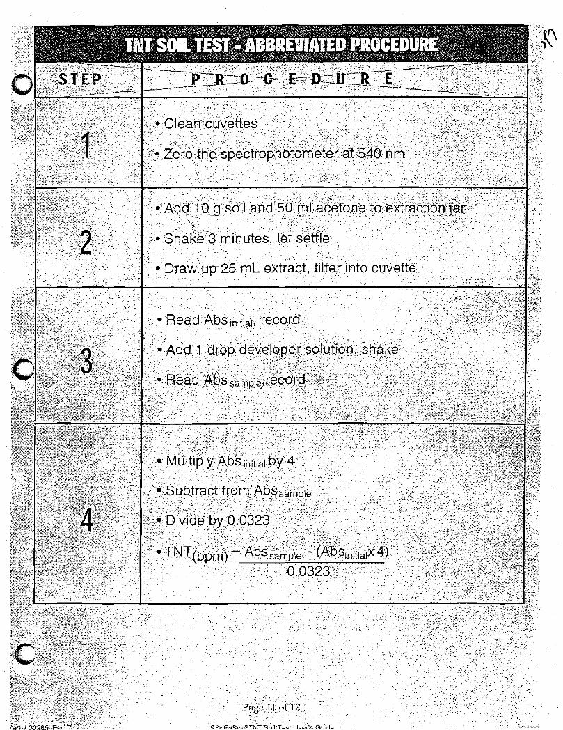

,.:- -,""":""",- .:~ -'--

Work Plans for Supplemental RI for Phase 4 Sites (Including Historical Site Assessment) – IAAAP
Loading and Packing Manuals Phase 4 Appendix
APPENDIX E LOADING AND PACKING MANUALS

" .EI.EMENTS OF ORDNANCE
A THEORETICAL S"il~C?SIS OF SHELL A1~D BONlB LOADlllG
Compiled by
Julian I. Kubisiak
Approved by
March 19, 1942
To be used. exclusively, inIowa Ordnance Plant, Burlington, I~/a
and not to be taken out or Plant limits.
:\C~
. ~
. ;!iI;.

PART 1
Prepared from Elements of Ordnance
a textbook for use of Cadets of U. S. Military Academy
by Lt. Col. Thomas d. Hayes
Eook pUblished by~ohn Wiley and Sons, New York
·c ••
f
jI
!.I
,."

What is Fixed. .Ammunit5.on?
In Fixed ~~llnitiont the powder~ cartridge case,and projectile are essembledtogether and loaded into thegun as a unit. The projectile is fixed r~gidly to thecartridge case. The propellent charge is loaded loose inthe cartridge case, and as the projectile is rigidly attached it rol1ows that this type of ammunition does notper~it the powder charge to be changed, in the ~ieldt fordifferent range zones.
Certa.in weapons using fixed a..-rnmuni tion have normalcho.!."ges and reduced char£8s to meet different tactical requirements, but the charges are not rearranged in the field.
What is Semi-Fixed .Amrn.unltion?-----------------Semi-Fixed Arnmunitiond:i.ffers from fixed ammuni
tion in that thB propellant is divided into incra~Gnts and~. loaded into a number of bags corresponding to the zones of
fire. The increments are numbered and placed in the casein a definite order.
The cartridge case is not crimped or securelyfast~ned to the projectile, and this permits removal ofthe projectile in the field, adjustment of the charge toth(~ zono desired by re:'lovin.g onf~or reare ba.gs of powder,and J:'e-as~embly. The rou.:1d is loaded into the gun as aunlt, as in fixed amr.o.llui tion.
TNTAmatolAmmonium Picrate
TetrylFulminate of MercuryLead Azide
TNT

Wha'e is TNT?
TNT s a crystalline powde~ of light-yellow colorsreueIDbl~s in appearance powder.ed bro~~ sugar; although indIfferent grades ot purity its color and appearance vary.
It is a triple nitrated toluene and composed of
CarbonHydrogenNitrogenOxygen
37.0% .2.2%
18.5%42.3%
It is also known as Trotyl, Tolite, Trilite,Trinol, Tritol, Tritolo and Fullpulver. Its full name isTrinitrotoluene.II. •
It melts e.t 'a temperature-of approximately 80-820 C.(Grade 1) (Grade 2 at 76° C.) The fa.ct that it melts at ateillporature less than boiling point gives it an advantageover other high explosives.
What :1, s TNT used for?.......__........_.... -_ ...--....
Used as a burBtin~ Charge for high explosive shells,. boml)s) mines) etc.,
. What is Arrcllon.ium Ni trate?
Ammonium Nitrate is the resultant s.alt of weakNitj;-ic·Acid and .Ammonia.. See supplement on page 8.
, "This mixture is concentrated, and the same liquoris poured into 8. mecIJul'1:tcal crystallizer which is equippedwith cold and hot water. After the liquor gets to a certaindegree the steam is turned off and the cold water valveopened very slowly. When the grain is formed, shut offpower, s.nd remove material to a screener and fill into sacks0:" oontainers ready :for use.
What is Junatol?
Amatol is a mixture of TNT and .A1lli"Iloni urn Nitrate.

How is thi3 accosnl13hed?--..;;..-- --;....-..;:.;..-~. " -The mixtUX3 is prepared by melting 1~ and incor~0~
rating it with ~~~onl~LQ Nitrate for a length of time suffi:c ie::nt to ensure "th6.t each grain of Al11..rrJ.onl um. Nitrate isthoroughly coated with TNT.
pnat_is f~atol used for1It is used as a burstine charge tor high explosive
shells and bombs.
~aii is TetrXl?
The high explosive Tetryl is derived froID coal=tarproducts. The che!'1ical proc.ess followed In its manufactu:reis coruplicated and results in the production of 1~ine,
crystalline powder of yellow color, stable at all storage+ oW"'O""'O+"~OOu .... ~J.l!....,04. ..... v ~__ ""' ......' •
Whe:t j.f3 it usee. far?----__,__ # ....' ....__... I __
Tetryl is a standard booster explosive. It isrea.dily exyloded by the detonator of -the fuze) and thevio18llce of its explosion ensures a hieh order of detocationof '~he ·b'J.rstlng cile-rea .
[email protected]~~lminat~._of rl!~~...£.urYl
It 1s the most sensit;lve explosive in our service.It detonates completely when brought to its iBuition tem~erature by flame or other means, and also is readilydetonated by friotion or shock.
Its characterlstio properties make it suitablefor U3e as an ingredient in friction and percussion primingcompo::d.'tions, and in d..3tonators.
.'....,.,
,.j
,;,:,!:
IIii,,!I,I..f
,I!
'j
i. ~!I
't,L[;t:~

~~:;119:t is it· made of?•..__._-_.---- . -----The raw materia.ls required for TIla:lUfBCt'1..lI'8 C:{
Fulra:lnate of Mercu.ry are 1~et8.11ic Mercury , Nitric Acid ~ and.Eth~rl Alcohol.
The m&uufactu=ing process is quite simple but veryhaz~rQous. It is generally prepared in relatively small lots.
It ls a hea\i"Y, crystalline f~olld, nearly white incolvT, and a very high degree of purity is e8sential.
YG:?:..a._~_ is Lead Azide~?
Lead Azide is a fine, cream colored eompotL."ld which:L3 tj::.l~I'Lu.ll}:y coming i.nto use as a standard detonator explosive, replacing Mercury Fulminate for certain uses. It isless ser.sitive to s~10ck ·i:.llan the fUlminate, flashes at a
. much higher t8ra.'pQ~;:·a..ture, is L:ore stable, and can be stor:::d·ro·.l.~-" , ........., ... J':." .._~""_ .----.1 -~ ... -_... _ ...~ -+ _'"I _ ...~.+_...:I -1-_ .. ,...,4- .....__ ,.. ...,~~~'_'1.;..._ J.L.LU'dJ..l.llJ..v\,;l .l:JVL·.l.V~"';:: \:;i·~vl.l. c:..v 1:l.1.0V\,:l.VOu.. VOtll.}!'O.Lo.lJ\.O.J..~'-:J V,.l.v,W,\..··..... v
deterIoration. It has ler,s tendency than the fulminate torefl./Jt wit;h metals. It reacts with copper so readily, thatit 15 usuall:r loaded into aluminum detonator capsules.
When usod in the explosive train to initiate thedetonation of the booster, it is brought to the ignitiontcmpe:re.tu.re by flam.e from.sOIT18 othe:." element .
.~n1at :i.s Bla.clc Powder?---------
Black Powder is a mechanical mixture· usually ofPotC.r.Siuril Nitrate, Charcoal ti.n.d SUlphur. Al though classedas a low or pro3reesive explosiYG, it must be regarded aso.al1ge~ou.~;; an(l. tl.'ea.cherou3 s end special precautions must beobserved in ita m~nufacture, handling, storage, and use., toavoid acciL~entis.
It is '1'1li'ce sensitiYe to hee.t from flame, friction,or spark, and bl~ns rapidly with evolution of extremely hotge.S~8.
It is used as a base charB6 or expelling charge in3hl'~~:~:n(,;1, igniter 01" igLliting cbe.rgo for propelling chargesin c~nnoD, blenk or salutiLe charges for cannon, time e1ementfJ in powder train fuzes, smoke-pUff charges) chal'e;es inpractlG8 bo!Q.os and practice brenades J a.nd pellets for primel~s
enG. fuzes.
.,
f
~ ' ..
,"f. . .
~.. I• j
I

.~.
':J1~ 0 + -; c :=• ...., (i n c,-.+ t:\ y .. ::o;....__ ... ~;..~ ...........- ... _--,.... --......---- --.... .... ~A ~..,........'". .; <) a mo~",1 "'o".L', :<:'"'"'. ,"'~, ·D·'C:O~"'::' 7"1,'"':' .".' ,,-'...'"ll.l ",,~~\...i...~y lJ __ ...... -... _ u ......",_...... __ ..... ,-,,_ _-'.1.,\,._ ... _ .....;,,> ~ "':_:..
'1Y'!+'-4~"""'j' '""nn evt~l"''':"\Ql "'l r",,~r=:~ 'l'r''''!I'\,'n 'lrl~'!')~--- ::l -;"t~"tC ',-." ;',..... _ .... Vv ..s",,;_c• ..L c_..... ..i.J.. O_.!.~l.... v _v""""'_"... : hl.t.~\'" t,l ..... _;:: I.J~ c:. .... _ .... v _ ........~• .....,. .. • .I. 4,. • _.;- ~.. ...... ...~ .... . ..
Jec.'0J....L.(-; aL.o. permlGS vne U;;;6 0..:. a cer ...&ln ·:'j;;tP;S· 0 ... ':':1::;S .;.. ,shellL1 e:f different kinc.s and calibars. It is S c: 8W':;C. I.,·r:~nG ~03e of the projectile to ~educa the siz3 of the cpsand to form e seat fo~ the fuze.
Yfuat is a Booster?
The Booster is the explosive element (usuallyTetrj'l) in the explosive train betv.3eh ·the detonator andthe bu.!'sting charge of High Explosi'Ve Shells.. r-t is some-tim"'''' no·,.,ta~ned ~'l', c ... \o~ ........ ""+""., ;"':"'\o"'t~ ..... ~ ....... 4 ......... , .... ,..-a..·rei< 4- 0..... .-.....--; i,J.....:.. ~.t." ........ tJ.J.l.J..U -&..I ..... \J1A..l- ..... ". :::- \,~ """'::'4~..1..u.O O""J.. \. "-4. I.)
the 6 rlal)ter and ertendin{; dc".'~n into the b'llrsting charge.
it/hat is a Fuze?-A Fuze is a mecha~ism for igniting or detonating
the bV~3tlng charge of a projectile, and performs thisfunotion either upon impact or at a certain time duringflight. WhE.:ll d.eslgned to function on impact it 1s clas:sedaB an impact or percussion fuze, end when designed to .func~t5_on at SOUle predeterLuned time after the projectilele::'"if8s tIle gun it is clas:Jcc1 as a time fuze. A COIllbinationfuze eorubines both time and. percussion elements. It isnOl"r~all:l set for timE; action but will function on impactshould the time elr~meL1t fail or should ir:pact occur beforethe time elem0nt causeG functioning_ They are classed acc0rding to the &sse~ble1position in the projeotile; thereare Point Fuzes) ~Nhicl1 are assembled into the nose of .shell, and Base Fuzes, which are ass.emb:ied into the base.
Wha (j 5. E" a Cartrj.d..2:,G Cass?---_. --"----
....,. .
. ····.~iJ~
In ou? service) Cartridge Cases are used in cannon' .up to J.05 mID. only, all lerg'8r caliber usine S8parat~ loading ~..m""l.rLition. The cartr'ldge case is ll1llde of brass of asiz'3 and shape to conform to the pcvlder cham.ber of the gun.The head of the case is relati~lely thj.ck and is providedwith a flange to aJlow easy extraction and for ssating theround in the gtm. In the c03nter of the head is the prImerseat, a circular hole into which the primer is seated by
~~ pressing to make a gas-tight joint. The primer hole isW ' cou.nter ...bored to a slight depth to recelve the primer flangs .
..... .....-..

1
1
1
1
V.Th~ t, :t s t ..h~ Ii ~"'1.. :rnJ?1"'Y f'i)~'::'\ (: ·~·'l21..:-_C)f t.ll~.. (;i'? ~ t~~ r: ~~" 1
It :ls to hold. tile prope:"l:.:lG ;";harge. ":',l e.:::.~:':: :: .. "'1t· he T'\rpsCI~'-""e ,...""" tJ16 PO""'!"!'" O'J:.S ""' .... ""\"",.,..,.:'"7. 1"1"'::> 'i"1"~"'" ·r·,·,:,· ..," ~ -. ,...- l--- - _~.J.. _.s. _ '\,-,\--,.- w-" 'J~~-r." .. .t"..... '."I ... ", J _ ... -' \, •• ,.. ~ '-.;.. .• 1
"a,::"Q +1 .... h .. l'T"l' ~'..""in~i· .. ", .. '''S''::: of' 1" ::> .... ~arrl"·.~ ':0 ~··... I.:."·.~···· ,"'" ....,"""" V-'O.LV J' ~ot;;..l. ..... v v ..... C i ... _........ .... v J,....., -'\ ........... iJ._·~ :...a.••J.\.l,. v.;..l._ ... '" ....... 1
pre~en~s ~he escape of gas to the rear. The cartridg~~~~~l
also serves to hold the projectile) p6r~~ttin0 the ~cu~1 ~,; 1be loaded into the gllIl in one ?perat.ioc.. 1
1
What is a Primer? 11
A Primer is a sensitive explosive or exploeive 1
mixture ~ which can be lenited readily by s i.mple means. 11
1
1
1
1
1
1
1
1
1
1
1
1
1
1
1
1
1
1
1
1
1
1
1
1
1
1
!:1I
i1
~ 1
i 1Ii,
1s a
The Dourrelet of e projectIle is a ~y11ndr1Jel
surface epproximstely 1/6 caliber in width in rear of ·~h~
heed. It. is accurat.ely machinec. cr @'r~ur..c te< f.!i iTS 2. 1Hi:::n~r ..rical clearance between i't and t.n l:' :"8.~~ds cf T.he rtf~.~T\V
varying .005 in. for sInal] ~E:.lib~;:-f) t·e to::: in. ~tJ 1.1 " •
gun.
What is a Bourrelet?.
There are several classes o1~ p=irners) name;.:!,?ropellent ?rimers, Percussion ?rimersl·Elect~ic, Fricti0nand Cornbination Prime:"s ..
What are Zone Increments?
They are s~all raw silk begs tllled with sThokelesspowder and are loaded i:l the cartridee case, as par"!; of t~€;
propelling charge.
It is a powder capable of producing the desiredmuzzle velocity, within the limit of' maximum pressure pre·scribed for the weapon.
It should be smokeless~ flashless~ and the prcductsof combustion should have no ccrrosive eft'set on ~,;,etais. Itshould be capable ot complete and unl~o~ ignition.
; ::r' ...";.- a~ •.... .....~~ i' ,. ,3' 2.._. i-
'.'

o ••
1·1ha-~ ere its fm:ctioD..a?_o ..._.__·.s_. ~
T~e esse~tial f~~ction8 of the oourrelet e~e toceno;er the fCi",,;';ard part of the pro,jectile in the DOT'92,:::[:"to prDvide a bearing or guide for its travel through thebore.
wr..a.t i.:L~~ RotatIng Band?
r-t is a copper band slightly larger in dlameterthan the bore of the gun, and tapered at the forward endccrr6spcnding to the forcing cone at the origin of therifling.
What are its functions?
,
,-.-.'
(al It centers the rear of the projectile in thegUll, ano.suppo:rts i.t in its travel through the bore.
(b) It locates the projectile initially in a fizedpcsition., in the gun, end holos it in place when the gun iselevated. This i~'3 necessary to secure uniform ballisticsfrom ro~nd to round.
(e) It acts es a gas check, ~reventing movement ofthe powder gases past 'the proj ectile.
•
What is a Projectile'?
A Projectile 1s a steel part of the shell whichis generally loaded with high explosive as the main burstingcharge. : ...../
. '
•
• , " ,,~ •._'~'''''''_''''''''''''''''.'_'''''',,",'''''~_ • rr.",!"", , '.:. ,14 " .- ••

_.__._----
~~onium nitrate 1s an a~oniu:n sa.lt of nitric 2cc5.cl..
It is prepared by s.d.ding a calculated amount of 2~O:~.
to a k~cYm ~motmt of dilute ~itrlc acido
The solution of the salt technically knovm as ~liQ.'llo::'
is con(~eDtrated by evaporation of water p c:!:.Istal1izedp dried ~
soreened and the dry salt is pecked into the air tight containe.:
Vfnen chemically PU=Si a.m~oni~ nitrate is a white,
crystalline substance o Technically pure salt has a bro..,."!lish-
e y'ellcrrv tint; p which is due to e. very small amount of iron preser-t
in ~t as an impu~1tYD
Jtl1.monium n1tZ's.te hS5 e strong tendency to abso~b
.moistuJ:e from the air and ·to dis3Cl·/6 itself in it.o It is
hygrosc:>pic 8.LlQ. deliq1.16Scent c Wb-en the moisture. content. ofItR('1IfrN~"'OnT,",,,~,,,u..·t(. tt:..lltAo:r.." D:tt'ot..V,"~ ~1t/"'Dr(;Qe,,' ~1f"'~1It1k. I--","r~c.rl'o"".ammonium ni~rat6 r8ac~es o~e~ 1/4 of enG ,~r cent it becomes
.',: t ...nsuitable for v.ee as an explosive a111 ID'.lSt be driod again o
Ammonium nitrate itself cannot be easily ignited or
c!:plodee. but organ~c i!.1~urlt:':.esii if present in it in the form of
A'ust o'hi T1 s T1_1 r~ce.s cf r··""'~ "'to' a~e 'n.ir:7h1 TT in·fleu'ilIIl8.ble and ~£..'fJ~ i ... 1:' S l! - ...·6 ... ; - • - C" -~ J
with am:.1onimn nitrete cc.n easily catch fire and will burn
intensely nnd rapidlYD
Ammonium nitrate is used tor the preparation of the
high explosive called amatol p which is a n:xture ct the aromcnh:7
nitl"'ate end rrNT. - .... .1 _'."" ..._." ~ • b. \. r....",
..... , -,;.......... '~" - - .. -"":' ,- ~ , -.,

Cleanliness and a healthy'chis work ..
condition ..: ':~"'l_ .. ", : ','~''''. . •..........~ ....~;.. -.. ;.;.:
Senarate lockers are used for work clothes and 3~:;:::0:~t
clot~~s,~when a complete change of clothing i3 ccmpulscrJ-~
Forbidden Articles
Among the articles that may not be taken into the loadi~S
or restricted areas are:
Anythin£ of metal
rocket knives
', .
j.:ecbanical pencils
Fountain pens
l,ietal containers
~hf)~'l'"It\' .. <:In--~-- r------l.:edicines, unless author1zed by Doctor Or L'1ne Supel'intendent
Use of Pass Dutton and Pocket Pass
Both passes are needed to Bain ~~5s1on to the work area.If you lC3e one, nobody can hope to use, it because trJBot1wr isnecessary also. ',[lherefore keep them separate so you cannot loseboth of them. V/ear the button on the left side of your coat or
',' jacket in plain sight. Its color shows the gu.arq, or youx foreman or Bupervisor ~hat you work lI'). his department. Have the otherpass ready to ~how the guard a.t tr..e cate when you enter or lea.vetile area..
Pacilitate the work of the euarda at all times. They arecur friends Guardinc us from the work of enemy agents.
3carches
Be prepared to be searched at any time by the guard whomu~t cL}eck up to see you do not brine any forbidden things ~ntothe area, particularly matches or l1£hters. Your lunch bucketand your car arc also subject to search.
/'"'
Don't Give Out Information Abou~ the Plant or About Your Job
~nemy aeents are on the look-out tor scraps of ir~ormationJunimportant b'J themselves per1"'.a.p5 but ~~y enable the agent to
..
-_._.. _._--_. -

I:tl&'OHI.if.\r..rION FOE. H.E;W OPERA~~lOE3___J • • I. U'$Q r •• •• _____
Thes0 notes do not !k~ve to be memorized but, be !'cad :s-."j.c~ l.'!.nderstoc-d before vC1). ber:-in 70U"t' work "_____I ~ C) V
As 1,.ate as January 1941; tl.":1ere were fe\~ of us 7r{.::.:) :.c-.. ~: ;thin.G about a-mmunition. The U.. S;.A. Isnot end never ai!::s,i t,,::.:(: ~
come a military or f'1ghtin[; nation - consequently we :b..ad to be!..:::!..y:;.·£rom a standing start to build up and equip our armed forceso .
, " ·.·t. ('
You who are going to make parte 1'01" use in our s.m.l~U!".t.1tlor'."(we call them components) will want to ask questions os 'Nell - a~lcthem - we knew the work is new to you and we· e:\:pect questions"
Safetz Shoe3 or Powder Shoes
You must wear approved shoos, which we call safety shoes. \jor powder shoes. This sotlllds dread.f'uJ." as thouSh your work would
t~~. terribly dangerous. Hovrever it ian't - the records sh01Y tr~t·,J'tlll.S work 1s twice as safe as ordinary indus trial or .factory work ..
.... t\-,;~Tne ree-son is that our employees have their work explained to tl:..e!~. 'j7'b~fore they start "'fork, especially the nature of explosives and .
: the handlinG of them. The result is an extremely low accident~rate •
::/ell, to return to the Safety Shoes.
r.rhey mus t be non-sparkinG snoes and mus tallow ele ctl'lci tyto escape from the body into the concrete floor.
A plain leather sale - sewn to the upper.
A rubber sale is no cood because it Ins.ulates the body :..t.!'lol
wont allow pody electricity to escape into the concrete floor.
Don't have any nails showinG or so useu that they maybecome exposed by wear.
Don't have any holes W:n.iC!l could pick up cri t or pie cpsof steel that could strike a spark.
The heel maybe either leather or rubber with no nailsor holes showlnc. It can be fastened \vith cement and a few woed,;:!?;Eers • An ordinary ileal can be converted to a safety heel bycementin.:..' a plo.in rubber or leather pie ce on it, and in tllis ..'10.:1
a pair of [ood shoes may be corw0rt~a into 3afc~J 3hoes.
7/29/43
-------_._ ...._......---- '- ",.'..- .

Do!:.i. J '':; :h~1.ve big eyels·ta or hooks" I'e iel bet"Cel' .;;(~
~p].2:!..n n'.:;10 S :1n ·~J:.w ~e a tOOl' 0
In. L'102t,t buildinga sandals a1"G not 'D,oZ'zd:G ted.., and :.:: .::m?~w·t not :tav'e O'l.l~ f1},:~3Y tos3 or open 1!OTk ..
!'t is a good pl.an to ksep yOUI' safety shoo is in yc)'.x:.~
look3r in tb..e change house; &nd travel in other shoes.., T:hs cl:e.:....>of ab.-res ea.ees the feet a:nd your work sheetS tfill alwsy3 be .L.""1 i.e 0C. ,corA1t1on'and~ - w~ch 1s an advantage in wet weather"
Donit pay a r~ncy pries for shoes. It isn't neces3ary#
Men should not wear neckties.
Men who work in tba storehouse a or packing roams; or woohandle heavy boxes of materials shouJ.d wear shoes that have s.reinforced toe l2iece' which prevents the tees from being bruisedOr cru.er...ed~a pac1o.ne case falls on them. This is advisedbecause a large proportion of the injuries in packing roans
.,gonaist of bruised ar smashed tees. Shoes with these strong tee,pleces usually oost a dollar more than plain safety shoes.it " 'I"W-~cnothing
,}~, ..'.} Your' clothing shou1d be plain and W'orlonanl1ke, free f'rom~ills and ornaments or anything tbB.t may catch in the appa.!'s-cU13
ou use.
, ,;1i .. ;;);:......
"
i, !.
I;
j;,-iII
iII.
.'1i,I',
Cotton 1s the moat suitable material for "women.
Women w111 find slacks verysu1table for" this work.
Avoid metal clasps, and see that z1.ppers are concealeda told ot the cloth. Use bone buttons - not metal one a •
Wrist watches, bangles and metal ornaments are not to be' 'Iworn. Signs.ls are given at the connnencement and end or workperi0d3 and therefore a watch 13 unnecessary.
WeSX' your badge on the left side of your shirt or coat80 that it 18 in plain sight.
or.
:':1 Operators bandl:1ng TNT, Tetryl or Black Pevrder must make a'complete change of clothing be:fore starting work. They are sup
~11ed with separate coveralle which are laundered a:fter 3 days188. They must also take a shower bath at the end. of' the shift
,before dress lng in the 1r street clot:D..e s • Th1;3 is cozr.puls ory ..
143t
.,II,
if
i,!!,..
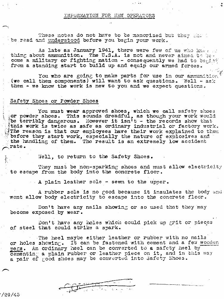
~..,.
INFORI.u~l'ION FOE. E~W OPERATOR3___, _", '.'F as ;q "--..~..
~Chese notes do not h::'\ve to 1:;0 m3rllorized 'but "Cr'~'3::{
. be !"zad a..""ld. .E£g,erstoc-d be.fore "Y'Gu. begin you.r work "
As Late as January 1941~ there were ~ew of us ~~0 ~"~ I
thinG about anmrun1t1on. The U.S;.A. is not and never ail::s.:i 'C": ,;'::.- ~
come a military or :righting nation - consequently we J1..ad to t~J~jLY.:;.·
from a standing start to buiJ.d up and equip our armed :fo:r'ces.. .. " '."
You who are going to make parts for use in our ammun:l.tiof'. ((we call them components) will want to ask questions. 'NeJ..l - 2E:tthem - we knew the work is new to you and we expect questions '"
Safety Shoe3 or Powder Shoes
You must wear approved shoes, which we call sa.:fety shoes~,;or powder shoes. This sounds dre·adf'ul., as thouSh your work wouldl~~_terribly dangerous. HOVTever it isn't - the records show tnat
.:ftaUs work 1a twice as safe as ordinary indus triaJ.. or factory work ..~gTne re&.son 1s that our employees have their work explained to tl:..e!~
. c.\' b~fore they start \'?'ork, especially the nature of explosives and .: the handling of' them. The result is an extremely low accident
~rate.
~ell, to return to the Safety Shoes.
r.rl1ey mus l; be non-sparkinG shoes and rous tallow electl'ici t:lto esca!J6 .from the body into the concrete floor.
A plain leather sale - sewn to the upper.
A rubber s ole is no Cood because it ins.ulates the body :.t.:l.Jwont allow pody electricity to escape into the concrete floor.
Don't have any nails showinG or so used. thD.t they maybecome exposed by wear.
Don't have any holes which could pick up c;rl t or piecpsof steel that could strike a spark.
The !~el maybe eitlwr leather or rubber with no nailsor holes showinC_ It can be fastened \vith cement and a fe-"I wocd(~~
~ecs- An ordinary neel can be converted to a safety lweI bycement in.:. a plain rubber or leather piece on it, and in tllis ','laya pair of [ood shoes may be cOlw~rt~d into ~a:fctJ 3ho~3.
'/29/4'0
~r-.~-'.'~.' .~.. ..
< ."(~'" .:~ ... :ti .... ,......
_.._---- _._-._ ......_.._...._- ..

· ... "
I
CG'r.'lpl::; te hIs pictUl"e of' Y11'12, t is done here oS! You nerver kJ'1::)':''j' ~:..: , ../cst their ini"orraaticul' 'Jut we do'"know they arB ;;!'J'-inS 1;0 1:::,:;;;;::;;;;' I
,--..., .,.. :1 -'- - , h d h d ... .., ,9nen:y 2.;:;.! C7"illeCL 50 uba:c e I!'...ay 0 a.s muc_ s.mase as :p03S:l0..i.'~; ~ ,T'n'ntO .,....1 a.". ~~L-:' 'F~~ _ "::;1"'\"-:' 1 09- ,:","-1"?.a. "" ...... .-'V't. ... -'3 ~"!~,...,~:.'..?,...~ .....-;- .,...~ ..:..~-!~. '~,-/-"',':-.'____ ::''''''''''_''' ..,__ .-- ........ "' ...... "" t..:,-y"",,, v~u o..J..L.,,! ..L.&..L..a."""""'.J.~~_V.J.,- ...~ Y' ....~,~...'~" .."' .• _~."""',.
it is sUEgesDed t:b..at you do not eXF...ibit you.:::' pass liu.tton ':7;:~:;~-:-,:.~,are awa.y f':'om the plant, because the button annC1l.t.""1ces that 7,:':.:.-"here and tha.t is an invitation to an enemy agent to quastic:n :T')/..,
:ITGIE'NE
~':ee1? trJ8 Hands and Person Clean
Explosives are irritants to the human syste~, in ~act theyare poisons, and we have more difficulty in trainin[ our operatorsto avoid the poisonous ef'fect than the explosive effect.. Somematerla18 are ,worse than others.
Mercury-Fulminate causes a pink rU3h on the hands or faceor· on whatever part absorbs the poison. Lead Azide produces tilesymptons of lead poisoning_ Tetryl stains the skin yellow and ifenough tetryl dust lodees in the hair it will bleach the }-1.air toa ~omewhat sickly yell~; thus producinc !l tet!'yl blcr..d.. A dc::eof'the dust absorbed into the respiratory tracts (easily done if
,the opera tor baa a cold) will cauae a rash like that of poison oakI~-\n the back of the hands, and on the ~ace and back of the neck •
.£t is very irritatinc and not easy to ge t rid of. _ THT produces apink rash in a similar manner, it is called Dermatitis and requirestreatment at our Hospital.
Beth Tetryl and Tr~
on the lips by taste afteror :fumes for 2 or 3 hours.throat.
have a bitter taste and can be detectedthe worker has been exposed to fine dustSome workers can detect it in the
: To avoid being a:ffected by these poisons the operator must,Lkeep the skin as clean as pOBd1ble. At each rest interval rinse~:or wash the handa in cold or tepid water to Sf) t rid o~ the loosel"duat, then use soap solution which actually dissolves and destroy'~~tetryl producing a pink solution 8S it does so, then rinse well''-and dry the handa • Always wash before eating, because ot~erwlse
lame or the poisonous dust on the hands i3 transferred to the.~ichee or other tood and goes directly into the systeme ',"ash
;,the race it you suspect dwst on the face. Don't use hot water,;';1:>e08use that robs tho ek1n of its natural grease and opens the~pore8 of the skin. If you have to use hot water, apply some ..... ccoor other good facial cream afterwards and rub it in thorouGhly.Don't leave the skin in a aticl~ condition ready to pick up mor~
r-C!ust.I
~pnqer Nails
;, 'l'hesa should be trimmed neatly so they do not project

;~a all ko.c~ what e oom:~\;ibl~ 1a ... it i8 30m5t1:J.=.~ ·::rh.i.,::.~:..'b1Jrns ~eadi!7 - like ~WOodl eeal~ oil; g;asolino 0 Tha38 ~tc~1"L;'2.~~.. "f'l~__ ~ ...... """,!J'_ tiI8 " ..... A ...~~_- ~ ..~ ltr,.tl "'" .. Ji ....~~_C']_ -.l.-..~--. r,\-",=-- __ t1'.a~ .:oQ-t.... '"'...,.:P\Clo,~'\' .." ,...~-,....~ .... ~''"'''O''';';; Wl-U.",," "'~J ..,"'"':....... .&0& ·9 ... 010<;;1 ... .... Q .... j ~.Il.iI.';;I.&..lo ~......g 1;1l....... oil ""!1..·Y ...."'i .:."":Lnor6Qi:lcd by b:ellcws or aiJ:' blast.. If O%;Tgen is 5u~pl:\ed L".:l~3-.t~~,~\,:',~of air; 'the heat ia extremely f1~:rcte. Hcmrevar, if ai.? and o:qg~):.:t· .~epl""evented. from reacb1ng the burning material tba f~e di~~ c;xi;·J' .it 1s smothered.
Explosives diU'er ~om O1"din s 14y oombustibles in that 'theydon f t need air or o:tygen to enabJ.e them to b'.:rn .-they alreadypossess the oxygsn. Conaequent1:r the;; burn in aJp1ts of. a:n.ysmoi;;>,wering we do to keep air and O%ygen away :from tbem~ They 'b1zttnand .wlll expJ.OOtt any oontaiuer in ",lUch we cont'inethem.
Gunpowder oontains nitre which 8uppJ.1ea o;cygen. to tb2oombustibles charcoal and Bu2phur flith which it is m.1xedo
. Primer ML~ contains pota8~1um chlorate a very powerfuloX)" gsn oarrier, mi:ed with a ~ombu.st1ble suoh as antimony suJ.phide
:r-or- lead sulphoc:rana'te. '
Gunpowder and Primer Mix are classed as 1.01t 6xploe1v0Sl 0
Most·modern explodlves oonsist of a combustible material~
to 'elfhich we b!!.ve added c::r::lgen by che!l'l1 cel treatment wi thQ'l..lt 'allowing the materia1- to bul-ne
The material may 00 cellulose, such as cotton or wood, and1s derived t':rom plant .fibre. When treated with nitric acid or amixture of nitric and sulphuric acidB it absol·ba" what chemistsoall the nitrate radical of the nitric acid, that 13, the partwhich contains oxygen. We call these products nitro-cotton (guncotton), and nitro cellulose (smokeless powder).
, Please note that we added ~~gen but that no burning tookplace, and the power o:f burning rapidly lies dormant in the explos2vuntil we bring it to life. .
Sometimea we treat a material with acid 8evera~ times toobtain a higher oxygen content and therefore a stronger and quickeracting explosive. 0115 like toluene or a .fluid like glycerine rr.D::tbe trea.ted, and in this way we obtain "nitro-glycerine" and lftrinitro-toluene". Such materials which have acqUired their oxygen
""""tbrough chemica.l action burn more rapidly than those which aremerely mixtures of powdered substances and they are more powerfll::. '.'
.._- - .

. ."
-....-:=:::.=-.---:::~ .. -~.,.. ..... : .':;..-':'~~-:~:::'~~.;.~,,:..;-, ...._-'': I ~ . .-' .; ..,., • • .'
7,.l~ ...... ~~_"~ '~~"9)1' ,...·\.1t~~'J'!o .~~I/"I""", ..?~':!:.~'),~ i'>,,;~,-"~ .""I'·.. ·:,~~ .. ).-4.IItt••~ "i:'""'1"'~" .Ho. ...... -: .. ~ .• "'"~.io ~::ii'Jj Q,~:l.t ~~u ~L;" ..;.b,k~ ,'J;l;.;;~i¥f~ .~~ **r~"'§ ~.'V t'~"f(.~~~~V,·..1 ~N.J;::': ..~ ~l .. v ~:.~~."" --., .. ,.
.~:-~~~ lf7::Lll e~~:ol;o:;?"~ .}i.-g ~~ge c"zn ~" ~re;&JtJ c·jtci(STi~fr#ryTI1' 'f~~~~ii-;.r:~~:Ji·'··-·-~~·:'·,,,..···'?2·J~"~~:~~:;-:\ t~lal-~ ~ ~~ .." 1,fa de:~::;~leped' .'th;::) l~0m~inder of th~ ~;q:;l,oB:L"j"'o:'} ....:.:.;_., ... ~.
·'T~~~.. .~~~~. ~i~:~~)~O~ 1;. ,-'}:j.:!0r'8f-6~~ t~Ot;_~.h.nu"~ C~ aO~:~ !€q ~e ~~~Cfl 't;2':; :..~.~~.~to 1'i~~veni ~ t'5~l: 01' :J.a~6cm oontac'Ci.ng an GX:91ozi''.;"e"
"_lIT,o_ t_A oi 0_ A_ t._'h~_ ,_"" A_ 1-1_' ::3_ n'I"l__~ h_1_A__ne_ ._~ ._~ c ~ n"" 7'11 1 A f'I ('\~h.ll .,:ul:.j 4 ,.. ..,- '"'~.~"i '. > ='~to!. _Ja - - - -- - -- .., .........--. .,),0 o~v.t: ............~
in work build1n~ and prohibiting bringing :m.a tohea or Ciga:;:o'3·Ct::.\ llightersN~:e.:::do::=~e::l::~::~ such things to be ~O~,.,:':''linto an e~ploe1ve. area~' ~
BreaJdng ,this rule means dlsm1aaal.
That ls, .t:be: onJ.y ,waY' to enf'orc~ suoh a rUle •, ,
In' the'restr1cted or vtorld.ng areas amoking is permittedinside tha lunch roams and soma1aolated of£1ce bUild~s but nowhere else. Eleotrlc l~ghters are ,provided where :smoking~ -pe;mItted: '
Leave', your matches at home or in your car. Sea:rch you:rr....,ockets, your lunch buoket, Sand your bag ~or odd ma:tcbel! and be am">3
JOu have none when you come to work.
. Use of High Explos1ves .
When we explode a ahell, bomb or mine in enemy' tarrltorv We<;)
use powerful explosives which we ,call high explosives 0 We choosethe most dest;;ructive explos1ves. It they are not destruotive ,theyareuaeles8. At the same time they D'lUlJt be sara _.to r£ndJ.e and 30we choose those tbat are not at all easy to explode. We can fire s.rifle bullet through our e::plos1ve without doing anything more treT.1.make a hole through it 0 We fill a shell with it and ehoot 1t out of'the gun at a terrifio velocity, and tba shock dues not e=plode t~
shell oharge. It wont explode when it crashes into the enmnyq~,t~
unless we install a device to make it explode. This 'device we calla fuze.
The Fuze'
The fuze if: a device which DJakes the shell charge ezplode atthe proper momf}nt. It may b6 instantaneous, a short delay, time orlone; delay. The fuze contains pl'imer mixture, a sen81tive la'S e:::p1:csive easily fired when struck be a firing pin or aqueettad by cru."'J~Cli::
action when the shell hits the target. The small exploaion and"......
"
.... ,.- '--_._- .. _,-.., , .. _.

.~'.-'~::~ 'q-.~:'J ..~:2:'~).:~ PA~j~'le1'f) ~~ii.::·:t~"l!!'0 ~~"1x.tel:r ·;~·t~·!;z ~;;bi~2g3' go:t;~g~) !.~ _... ,,'.;:rA ...... ';'O"-:;.,.. .~... ",... ~b.-4- ,""'~.~.:,......, " ..o:.",~ lp""·,~e·'>-Jt':"'\,·" _~"","h.o~:"l.70 O~ i-t i~~ "'::"n_...~~.....tRe ~t~o ?~.~f'~ :D.,~~_'li;,7·"'.. (.':""'..:.... :...: .."t' ~V":.I ............ .,.., ""-"...,:.."' ""'·~tIooII'-".obooA'-'C ................-....<GoI~- - __ ~ __ -.- ". • ..
'';1 ;·~.. ·i f~ ,:-:\ ;~ r:t t!~nft'il .J; 1-' ~7 ~,~ ..~ 1'''1 J7n ~~'i;""\1 ~t.",","'; 't;;:_~ . :f.t:'1h ~.. n'r, (';;)-'.."0" tr...·~ ~~- 7'<J'J{'~ ....~ ~ ~""'·t·'''-:O : :','''' . _ "~,O_""""i.J J' _. 4..,ilI~...:.....v..1.1..~..c..IJ"'" ~l"'"",,-- 'l;;.l/..:" y_~~~_", 1,; ~ ,- .,-"... -'- . ..,."""",,~ '~, ""' -_ •. :-.J ...
~')::7'C9 1:,111:: 31::121 not enoutib..- t:or O~.. "O".ll>j.1-osa: It will hc~]o'V,:;:'.... .'..... .?, ~ "1 '.".ot ._1,.r...~"",,\ .~, _ 1 .l''''''olI''S.Jt ~• .r.A - m~~~'"1 .....:.~ tre ..-....~ ! .at...... .tl.o. _ J- .... ..-- _.~ -~ , " •
\:';'"" O;.. ~...1. ....~ ~~;";..i. ~...ra..l ·Jo..·J~.~'7~...,9 ~,-,v..:..tl ....... 5' ~.;.~ ..;.'"..J".;(I..: • .;, .:-;.,:, ..J... i1JIC' :,1:"'.!...:.·':'':'' :~ ... ~... _- ,. '~.~.,.. -....
TNT or B.ny o·tn9!" high ezplos1ve ar.d ~lte :1.t de7elop it~ 1"::'.11 ~');~':;~-,-
EZulosive Trains.< CO: _ t ~
Vie therefore use a series or train of' explosives ·to gi7~J
us more and m01"e power until it is sufficient to explode the shel:.charge. In U. 3:11 ammunition we use the .following 6rplosiv8a 3 eac2:.oharge being stronger than the one which.precedes it e
Explosive Train for Instantaneous Action
Pr~er Mix, Lead AZide, Tetryl, TNT or Amatol.
This train will expiode the ahell before it bas time topenetrate the target.
-;',"'t ..
.. . . Primer Mix, Army Black Powder, Lead AZide, Tetryl,TNT orr'Jatol. .
Thi3 train giyos the shell or bomb time'to penotrate a wallor embanlanent ~ plunge through sever!-ll floors or Q big building orinto a dugout before' it explodes. We start with PrimeI' Mixture a3 -~",~ .before and then deJ.ay the aotion by interposing Arr:Jry Blaok Powder J'between it and 'the Lead Azide. . ....
.. \~".\f-" .
f:·Arrrry' Black Powder in a looos condition t"laehea quiCkly but j'~
when compressed into a solid blook tightlY,tilling a metal tube it ;burna at a relatively slow rate. To give a rough idea of: the speedwe may Bay that a solid oore 1/10" long takes approx1Il'\.ately 1/10aecond to burn. This enables us to arrange for any. short delay .desired in a fuze.
Components
Charges ot explosives are pressed into a firm hard massin small containers wh,",oh in turn are fitted in oavities in ths.fuze. Loose powder ot any desoription 18 extremely dangerous asit would oQuaepremature exploe1on due to friotion setting it off ..
I""'" In your work of assembling these part:! tArry 8p1~d pOJ9'del".lBt be wiped up at enoe with a moist olathe It 18 dan,gercn.13 to
hB.v~ dU3 t or dirt anywhere in the work plaoe. Cl~~"'ll.1ne:Js 113
_......'---:--:----- .._--_:- ..

extremely iluport8r:.t in tms "Work - YC/Ul."' ;safe"'!:;:: dS:;;:;:7:cts· '.. ;11~ess and careru2n~s3,
The mna,11 parts 'tLs~d in a. :fuze or in a ro~.:..':~:c.:,:;~, .;:':':·l.L
are called components and are named accord.i..:.g to ·tl::.5 e':1:?2..;:;.'.charges in them and the work -they perform, fer "j"1,9tar.:.;;~:;
Contains Work Performed
Army Black Powder Delays the explosion.
W.aen flame..j}::azide 1 t e·;epl:..
'{fhsn struclr.pin.
Ey ta 'l.rl ng' <::: •._ f;;;. ~"
to burn tb.rou~
Relays the explosionor passes it on.
Primer lI'ixture starts the explos ion ..
Lead azide
Name
Delay
Primer
Relay
Head Primer mixtureDetonator. &
Lead azide
Starts the explosion,and
Intensiries the explosion.
When struck 1.:pin. ..
Because azidi::explosive .'.
, ' ....:
.Booster Lead azideDetonator &
Tetryl
Lead Cup·Tetryl
Picks up the explosion,and.
Sets o'£f tetryl.
Leads the explosiondown to the boostercup.
Be cause i {~'lt:~:
and a hi[h eip
By explodin£with Tetryl IE .cup.
Explodes the ehellbursting charge.
Bursts the ehell orbomb.
By explodingshe11 charge It
By explodlnEa. large volumegas e s whl ch bu...shell.
Fraseentation Bomb
When we wish Q shell or banb to burs t the moment thD._strikes we use an instantaneous t'uze and Gall the bomlJa :frc..:·mentation bomb. We use it against enemy personnel, or tran~columns, or to destroy airplanes on the ground.
Demolition Bomb
When we wish it to burst a rnnall fraction of a 80COLstriking '"' usa a short de lay fuze and call the bomb a demo::bomb. We uee 1t to de :!Strey earthworks or buildings 1 dUJ.;;out:-.
,. ...., .' .... '.~ .. ~••• - •• , __ CT"
-_._._-_.. ........ ~"... '-~

Work Plan for Supplemental Remedial Investigation for Phase 4 (Including Historical Site Assessment) – IAAAP
Complete Rounds Manual Appendices
APPENDIX E COMPLETE ROUNDS MANUAL SUMMARY

Work Plan for Supplemental Remedial Investigation Phase 4 (Including Historical Site Assessment) – IAAAP
Complete Rounds Manual Appendices
INTRODUCTION TO AMMUNITION, EXPLOSIVES, AND WEAPONS PRODUCTION TERMINOLOGY
The material in this section has been gleaned from IAAAP’s historical Document #113 and has been included to for the reader to better understand historical production line operations at IAAAP.
A Round of Ammunition and How It Functions A round is composed of a shell containing shot or a bursting charge nosed with some firing device and having behind it other explosives in a container under the shell to propel it from the gun. To be considered satisfactory, ammunition must be intense in its action and uniform from round to round; it must be safe to handle, transport, and store; it must be certain to function; and it must be produced speedily yet safely.
Various kinds of shells and bombs and the devices which cause them to function will be described in the lectures which are to follow, after giving you a little more of the general picture.
A complete round of artillery ammunition, such as this Plant will load and assemble, was recently described by General H. H. Zoring of the Ammunition Division in Washington, “The rookie pulls a lanyard to make a hammer strike the firing pin...the firing pin sets off the percussion element in the base of the powder charge…the percussion element ignites the primer...the primer ignites the propelling charges...the propelling charge burns into gas...the gas pushes the projectile out of the gun or cannon. (The projectile does not explode in the gun because its gizzards are locked until it beings to spin while in flight.) The centrifugal force created by the spinning action causes the locking jaws in the fuze of the projectile to spread apart, and the shell becomes “armed,” so that when it strikes in the enemy’s lines, the impact on the nose of the shell sets off the detonator...the detonator sets off the booster...the booster sets off the bursting charge...the projectile is blown to smithereens, and its red hot fragments demolish the enemy!”
The various production lines in this Iowa Ordnance Plant comprise shell and bomb loading and also the preparation, loading, assembling, inspection, packing, and shipping of fuzes, boosters, detonators, percussion elements, and artillery primers.
The shells are of the heavy artillery type, ranging from 3 to 6 in. in diameter. The bombs range from 50 lb to 6,000 lb each. The large fellows are 3 ft in diameter and 14 ft long.
The fuzes, boosters, and primers are small components, weighting from 1/2 lb to 5 lb, which go into the nose or base of the shell or bomb, according to the purpose for which it is intended. Detonators and percussion elements are quite small, but tricky explosive parts which go into the fuzes, boosters, and artillery primers. In addition to the foregoing, there are many tiny springs, arming pins, and other inert gadgets to be sorted and assembled. (Document # 113)
Explosives An explosive is a material that is not in its most stable form. It cannot change of its own accord, but we can start the process by fire, or sometimes just by a spark, or by friction or shock. A rise in temperature or a blow applied to a small portion may also start the change. When this

Work Plan for Supplemental Remedial Investigation Phase 4 (Including Historical Site Assessment) – IAAAP
Complete Rounds Manual Appendices
transformation takes place, we have an explosion. It is almost instantaneous, and an enormous quantity of heat and gas is liberated.
Military Explosives are divided into two classes: (1) High Explosives and (2) Low Explosives.
High Explosives include trinitrotoluene (TNT), tetryl, TNT-ammonium nitrate explosive (TNA), lead azide, mercury fulminate, amatol, picric acid, ammonium picrate, dynamite, etc. In the fastest of these fast explosives, the change is practically instantaneous. It is so rapid that we speak of it as a “detonation.” This speed and violence make High Explosives unsuitable for use as propellants, because the shock would burst the barrel of a gun or rifle. It is this characteristic, however, that makes such explosives useful for the bursting charges of shells and bombs in that they produce the necessary fragmentation to give great destructive results. The word “brisance” is used to designate this breaking power. It is derived from the French word, “brisser,” to break.
Low Explosives include Army black powder and nitrocellulose powders. The action of nitrocellulose plastic base powders is more rapid than that of black powder; the shock of the explosion is sharper; and it is possible to add ingredients to control or modify the speed of reaction or the brightness of the flame. Nitrocellulose explosives are very useful as “propellants” to fire bullets out of rifles and guns, one of the reasons being that they are relatively “smokeless.”
Military ammunition must stand great heat or extreme cold, also rain and moisture. Many commercial powders are taboo, because they contain ingredients which are unreliable under military conditions.
Black Powder and Primer Mixture are mechanical combinations of powdered substances. At least one substance must be a material that burns easily, such as charcoal, antimony sulphide, or sulphur.
Army Black Powder is a mixture of charcoal, sulphur, and potassium nitrate. Changing the ratio of ingredients changes the burning rate. Black powder is exploded by flame, spark, or friction.
Primer Mix contains potassium chlorate instead of nitrate and is easily exploded by friction or a very light blow.
Such mixtures must be handled with great care whether loaded in dry or wet form. They are used to start the explosive train of a propelling charge in a gun, or of the bursting charge in a projectile. Carborundum or powdered glass is sometimes added to the formula to increase its sensitivity. In some cases, the strength of the primer mixture is further increased by adding a little mercury fulminate, lead azide, or TNT – only 5 percent or 50, and even this necessitates the greatest precaution in handling. (Document # 113)
Weapons Ordnance is a general name for all kinds of weapons and appliances used in war. This covers rifles and cannon, their mountings, their means of conveyance, their ammunition and other supplies, and also the machines, tools, and other facilities necessary to make and repair anything having to do with weapons.

Work Plan for Supplemental Remedial Investigation Phase 4 (Including Historical Site Assessment) – IAAAP
Complete Rounds Manual Appendices
Ammunition means projectiles such as bullets, shells, bombs, hand grenades, etc., with their necessary powders, primers, detonators, and fuzes.
There are two kinds of ammunition:
for small arms, which includes pistol, rifle, and machine gun cartridges and sporting ammunition
for artillery, such as shells and bombs.
Artillery ammunition to be loaded at this Plant includes light, medium, and heavy shells, and demolition and fragmentation bombs. While there is no assignment to make small arms ammunition here, the loading of complete rounds of shells and bombs involves the loading of many very small pieces which are components of the shell proper; so, as said before, there will be opportunities for all capable applicants. For instance, we have percussion elements as small as 3/10-in. diameter, of which 7,000 consume only one pound of explosive; or you might prefer to work on detonators, 1,000 for a pound; or boosters, which run anywhere from 10 to 100 for a pound of explosives; or primers, from 20 to 300 for a pound; and propellants, from 1/2 to 100 lb per charge; the shell proper, 2 lb to 200 lb; and finally, the bomb, from 20 lb to 2,000 lb each. Of the latter class, those that are 23 in. in diameter are nearly 8 ft high. They contain 1,077 lb of amatol for the bursting charge. Yet that is not all; even before our 2,000-lb Bomb Line was finished, orders came from Washington to build and equip for loading bombs weighing up to 6,000 lb each.
Munitions is a broader term than either “Ammunition” or “Ordnance” in that it covers military materials of all kinds.
Artillery is a general name for relatively heavy weapons such as cannon, guns, howitzers, and mortars with their equipment of carriages, shells, and conveyances and the personnel to operate them.
Light artillery comprises the 75-mm. field gun (3-in. bore) and the 105-mm. howitzer (4.2-in. bore), both of which are mobile.
Medium and Heavy Artillery. The 155-mm. gun and 8-in. howitzer are classified as “medium,” and anything larger as “heavy artillery.” The most powerful mobile gun of the U.S. Army is the 14 in. on railway carriage. The 16 in. mounted on a barbette is the largest of all.
Howitzer is a relatively short-barrel cannon which fires a heavy projectile at high elevation (high angle fire) with a comparatively small propellant charge and low muzzle velocity in contrast to the ordinary field gun, which fires a lighter projectile at low angular elevation (direct fire) with a large propellant charge and high muzzle velocity. In most armies, one-fourth of field artillery consists of howitzers and three-fourths of guns.
Trench Mortar is a very light weapon, which an infantryman carries into the front trenches where it performs work similar to that of a small howitzer in support of the infantry. It has a smooth bore and is loaded by dropping the round into the muzzle. When the shell or bomb reaches the bottom, it strikes a firing pin, which sets off the primer. This ignites the propellant charge, which hurls the bomb into enemy territory. The empty tail fin assembly, which held the

Work Plan for Supplemental Remedial Investigation Phase 4 (Including Historical Site Assessment) – IAAAP
Complete Rounds Manual Appendices
powder, leaves the mortar, because it is fastened to the rear of the projectile. Thus, the mortar is left clear and ready for another round.
The following descriptions are quoted with some alterations from “Elements of Ordnance” by Colonel Thomas J. Hayes, published in 1938 by John Wiley & Sons, Inc.:
Shrapnel is a projectile designed to carry a large number of spherical shots and discharge them over an extended area. The shrapnel body is a drawn-steel tube with solid base. A diaphragm divides it into two parts – the base cavity which contains a bursting charge of black powder, and the space above the diaphragm filled with ½-in. shrapnel balls composed of lead alloyed with antimony.
When the gun is fired, the shock of discharge arms the fuze and ignites a powder train. This train can be adjusted to burn for a desired number of seconds and is set to explode when the projectile reaches some point above and in front of the target. The explosion of the base charge does not rupture the case, but ejects the diaphragm, balls, head, and fuze; because of the rotation of the projectile, the shrapnel balls are dispersed to right and left.
Shell Shell is another kind of artillery projectile. Shells are classified as low explosive, high explosive, armor-piercing, and chemical, according to the charges they contain and their uses.
Low explosive shells contain black powder bursting charges. They are used in 37-mm. and 2.24-in. guns.
High explosive shells are used primarily for fragmentation or demolition.
Chemical shells are filled with chemicals which start fires, make smoke screens, or release gasses which attack the human body. They are similar to high explosive shells in design and size. The filler may be either solid or liquid. They have fuzes with superquick action to make them burst above ground. For small shells, the burster is tetryl, but large shells use both tetryl and TNT.
Armor-piercing shells are used to penetrate the armor of ships and explode inside. They are equipped with delay-action base fuzes and must have sufficient strength to pierce armor plate at battle ranges without breaking up and still be in good condition for effective delayed-action.
To obtain this strength, the shell is constructed of forged alloy steel, heat-treated to produce the best combination of hardness and toughness. The walls are relatively thick; the explosive cavity is small and extends only about half the length of the projectile proper.
Deck-piercing shells have thinner walls and more space for the explosive. They are designed for use in seacoast mortars and for plunging fire against the thinner deck armor ships.
Trench mortar shells are streamlined projectiles which are stabilized in flight by tail fins. Three types are used: high explosive, smoke, and practice.
Bombs The standard types are fragmentation, demolition, chemical, practice, drill, and gage.

Work Plan for Supplemental Remedial Investigation Phase 4 (Including Historical Site Assessment) – IAAAP
Complete Rounds Manual Appendices
Fragmentation. Destructive effect of this type is obtained largely by scattering the fragments of the bomb case and other metal components at high velocity. It is used primarily by attack aviation against ground targets, such as personnel, animals, light material targets, etc.
Demolition. The most important type of explosive bomb is designed for the destruction of material targets. It is thin-walled to permit a maximum charge, but it must have sufficient strength to withstand impact against hard-surface targets and penetrate them intact before delay-action detonation takes place.
Chemical bombs are filled with agents which produce effects similar to those just described under “Chemical shells.”
Practice bombs are used for training in marksmanship and in the operation of the safety and arming features of bomb racks.
Drill and gage bombs are standard bombs loaded with inert materials equal in weight to the regular powder. Drill bombs are used for training purposes in fitting fuzes, handling and loading bombs on airplanes, and for bomb practice. Gage bombs are used in testing bomb racks, release mechanisms, etc., to see that they are of proper size.
Components of Shells and Bombs Fuzes
The word “fuze” means something that starts an explosion. It is an initiator which detonates and is used for ordnance purposes. It may be the slow-burning type or the instantaneous type, fired by electrical, mechanical or chemical means.
In general, there are three ways in which fuzes act:
To cause the shell to explode immediately upon impact, giving a destructive surface effect.
Have it ignite upon impact and then explode after a predetermined short or long delay. Each enables the shell to burst after penetrating earthworks or concrete or a sheet or steel of plates. The short delay is much used for shellfire which strikes the ground a short distance in front of the enemy’s position, then ricochets or bounces off the ground and bursts a short distance further on just over the enemy’s head.
Causes the shell to burst in mid-air before striking any target, as used for shrapnel, anti-aircraft, and high explosive shellfire.
Superquick (SQ) fuze acts so quickly that the shell explodes before it begins to penetrate the target.
Point Detonating (P.D.) Fuze. When the fuze is screwed on the nose of the shell, it is known as P.D. Fuze.
Base Detonating (B.D.) Fuze. When fitted into the base of the shell, it is called B.D. Fuze. In each case, a firing pin strikes a detonator at the instant the shell strikes the target and “whang” it goes.

Work Plan for Supplemental Remedial Investigation Phase 4 (Including Historical Site Assessment) – IAAAP
Complete Rounds Manual Appendices
Delay Action Fuze takes a definite time before “flashing” the fire into the rest of the fuze. All fuzes of a given designation have the same delay interval. The firing pin strikes a primer which ignites a black powder pellet, adjusted to take the desired burning time.
Time Fuze is used when the shell is to explode in mid-air and before striking the target. Firing the gun causes a primer to ignite a train or ring of Army black powder which the artilleryman adjusts for burning time. Time fuzes are chiefly used for shrapnel which must explode above the target, and for anti-aircraft work or against personnel. Time “rings” are “set” by the gunner immediately before firing.
The fuze is screwed into the shell or bomb and staked there for keeps. Details of fuze construction will be described in subsequent lectures, but will now consider some components.
Detonators are small cylinders or capsules containing explosives. Some are arranged to fire when struck by a firing pin; others are fired by the flash from a relay cup which passes the fire on from a primer.
Delay is a pellet of compressed Army black powder that is often used to delay the explosion of a shell or bomb. The primer fires the delay pellet, which takes an appreciable time to burn through and pass the flash on to the relay and so to the bursting charge.
Relays are small aluminum cylinders filled with lead azide. A relay receives a flash from a primer or a delay element, boosts it and passes it on to the next element in the explosive train.
Percussion Elements perform like the “cap” on Grandfather’s muzzle-loaded shotgun which, when hit by the hammer, exploded and fired the adjacent charge of gunpowder. It consists of a small metal cup containing friction mixture or “Primer Mix” pressed in place with a thin paper cover. Afterwards, an anvil is squeezed in to partly close the tope of the cup and keep the powder in place. In artillery work, these little elements are used at both ends of the job – in the bottom of the cartridge case to get the shell out of the gun or mortar; also, in the fuze on the nose of the projectile to start the train of explosives.
Percussion Primer in small arms is called a percussion cap as explained above, and the slightly different type used in fuzes is called a percussion element.
Artillery Primer is a combination of a percussion element and a brass cylinder having perforated walls, which is charged with black powder. The percussion element is struck by the firing hammer, explodes and ignites the black powder in the cylinder, which, in turn, fires the smokeless powder in the cartridge case in the shell.
Booster Cups and Boosters. Every artillery fuze has a booster cup containing a large charge of tetryl which increases enormously the initial impulse received from the fuze train, and insures complete detonation of the bursting charge of the shell. Sometimes the booster cup has an intermediate booster to step up the fuze train and to act as a safety device to prevent premature firing. Strictly speaking, both these things are boosters, since each of them “boosts” the detonation, but technically, there is a difference; the booster has a safety mechanism with a detonator, and the booster cup is merely a cup which contains a large pellet of tetryl or some other brisant explosive.

Work Plan for Supplemental Remedial Investigation Phase 4 (Including Historical Site Assessment) – IAAAP
Complete Rounds Manual Appendices
Cartridge Case is the propellent charge, usually smokeless powder, which projects the shell out of the gun and is loaded in a cylindrical brass container or cartridge case which fits the bore of the gun. In “fixed ammunition” the case with its propellent charge is rigidly fastened to the projectile, the shell being swaged into the open end of the case after both are loaded. In the bottom of the case is an artillery primer containing Army black powder. This primer is headed with a percussion element which, as said before, contains an anvil and some friction mixture which ignites “when the rookie pulls the lanyard, which releases the trigger to do the dirty work”.
Increments in “semi-fixed ammunition,” the projectile is separate from the case which contains the propellant in small silk bags, four or more of them, called “increments,” one or more of which may be removed to shorten the range of fire. Increments are also attached to the stabilizer or tall fins of bombs for trench mortars. This gives the infantryman a ready means of altering the range of fire. (Document # 113)
Loading High Explosive Shells and Bombs When received at the Plant, the shells have either wooden or metal shipping plugs screwed in the nose, and the first process is the removal of these plugs. This is a machine operation. The removers have steel points attached to a revolving shaft, and these engage the plug and unscrew it.
From the receiving building, the shells are carried forward to the Painting Building and to each successive stage on conveyor lines, which finally converge in the Packing and Shipping Building.
After being painted and warmed, the shells are conveyed to the Melt Loading Building where the prescribed charges are run into the shells, sometimes straight TNT and sometimes a mixture of TNT and ammonium nitrate, called amatol, varying in proportions from 50-50 to 80-20. The mixture is prepared by melting TNT and incorporating ammonium nitrate with it for a length of time sufficient to ensure that each grain of ammonium nitrate is thoroughly coated with TNT.
The ammonium nitrate is crushed and dried before mixing. The TNT is melted and the two are mixed in the kettle room. The kettles have hot water jackets heated by a steam coil within the jacket, and each kettle is about 1,800 lb, and a melt is dropped about every 30 minutes. When a mixture is used, the amount of TNT needed is first melted in the kettle and then hot ammonium nitrate is added until a full charge of proper proportions is obtained.
When TNT is poured, the material is drawn off into stirring tubes. Stirring is necessary, because the rapid crystallization of TNT, when cooling begins, might cause cavitation in the charge. Cavitation means the formation of cavities in the material due to shrinkage as it solidifies. The material is therefore stirred with wooden or aluminum paddles to break up large crystals into smaller crystals and give a more even charge. The explosive is the drawn off into buckets for pouring into the shells. The empty shell bodies, before the pouring process, and thoroughly cleaned of dirt and grease with a 15 per cent caustic soda solution, which is sprayed into the shell through a spray nozzle. On the way to the pouring room, under certain atmospheric conditions, the shells may have to be preheated in specially designed apparatus so that they will not sweat in the pouring process. When assured that the inside of the shell is thoroughly dried and at

Work Plan for Supplemental Remedial Investigation Phase 4 (Including Historical Site Assessment) – IAAAP
Complete Rounds Manual Appendices
comfortable room temperature, a funnel is placed in the nose of each, through which the charge is poured in small quantities with a short interval between each pouring. In the case of 75 mm shell, there is only one pouring. When straight TNT is used, it is poured to the height of the bourrelet, and then straight TNT is poured to the top of the funnel. This method permits reasonably rapid production. The portion of the explosive in the funnel is termed the “riser,” and the purpose of filling above the shell is merely that the point of extreme crystallization, which takes place rapidly when the explosive is exposed to air, may be above the outside of the shell itself. To further reduce the possibility of cavitation when 50-50 is poured, a soft rod about 3/8 in. in diameter is puddled into the shell charge just after the pouring, and withdrawn in a few seconds, thus having a tendency to make crystallization uniform throughout. Results have shown that when skillfully done this so-called “puddling” produces a charge of even texture and of the specified density.
After the charge is poured, the solidified riser head is removed and reused later, the use of 50 percent proportion being permissible, provided it is within 48 hours of the original pouring.
The shells now go to the cooling room where they are stored until completely cooled. Small ones take 8 or 9 hours, and big ones require several days. They are then drilled to receive the booster; the thread is thoroughly cleaned and vacuumed to remove all explosive that may have collected; and then in the event the booster is not placed immediately, the cavity for the booster in some shells is shellacked to waterproof it. In other types, a hard plastic liner cup is inserted to prevent chemical reaction between the bursting charge and the soft metal of the booster cup.
While all this work on the “business end” of the shell is going along on one Line, the large cartridge cases are being loaded with projection charges in a separate line of buildings.
The cartridge case is filled with smokeless powder on automatic weighing machines. The shell bodies and cartridge cases then go to the Assembling Building, where they are partly assembled by hand and finally fastened together in an assembling and crimping machine. Gauging and weighing come next, and then the shells are taken to the building where the booster is placed in the cavity. They are then sent on skids to the Packing Building and thence to the Shipping Building.
Fire prevention precautions are carried out rigidly. Plant protection, by maintaining cleanliness, is strictly enforced. Operating buildings are frequently and thoroughly inspected to see that no rubbish accumulates, the purpose being not to let it pile up and then dispose of it, but actually to prevent accumulation.
Buildings where TNT is poured undergo constant cleaning and are flushed out with steam daily. Exhaust air systems are installed to carry away the fumes and dust. A safety patrol attends to the cleaning up of TNT dust and the clearing away of waste. (Document # 113)