tms320f2812-controller area network
TRANSCRIPT
DSP28 - Controller Area Network 9 - 1
Introduction One of the most successful stories of the developments in automotive electronics in the last decade of the 20th century has been the introduction of distributed electronic control units in passenger cars. Customer demands, the dramatic decline in costs of electronic devices and the amazing increase in the computing power of microcontrollers has led to more and more electronic applications in a car. Consequently, there is a strong need for all those devices to communicate with each other, to share information or to co-ordinate their interactions.
The “Controller Area Network” was introduced and patented by Robert Bosch GmbH, Germany. After short and heavy competition, CAN was accepted by almost all manufacturers. Nowadays, it is the basic network system in nearly all automotive manufacturers’ shiny new cars. Latest products use CAN accompanied by other network systems such as LIN (a low-cost serial net for body electronics), MOST (used for in-car entertainment) or Flexray (used for safety critical communication) to tailor the different needs for communication with dedicated net structures.
Because CAN has high and reliable data rates, built-in failure detection and cost-effective prices for controllers, nowadays it is also widely used outside automotive electronics. It is a standard for industrial applications such as a “Field Bus” used in process control. A large number of distributed control systems for mechanical devices use CAN as their “backbone”.
9 - 2
What is “CAN”what does CAN mean ?
it stands for : Controller Area Network• it is a dedicated development of the automotive electronic
industry• it is a digital bus system for the use between electronic
systems inside a car• it uses a synchronous serial data transmission why is it important to know about CAN ?
among the car network systems it is the market leader• it is the in car backbone network of BMW, Volkswagen ,
Daimler-Chrysler , Porsche and more manufacturers• CAN covers some unique internal features you can’t find
elsewhere..• there is an increasing number of CAN-applications also
outside the automotive industry
C28x Controller Area Network

Module Topics
9 - 2 DSP28 - Controller Area Network
Module Topics C28x Controller Area Network.................................................................................................................9-1
Introduction .............................................................................................................................................9-1 Module Topics..........................................................................................................................................9-2 CAN Requirements...................................................................................................................................9-4 Basic CAN Features.................................................................................................................................9-5 CAN Implementation................................................................................................................................9-6 CAN Data Frame .....................................................................................................................................9-7 CAN Automotive Classes .........................................................................................................................9-9 ISO Standardization...............................................................................................................................9-10 CAN Application Layer..........................................................................................................................9-11 CAN Bus Arbitration – CSMA/CA .........................................................................................................9-12 High Speed CAN ....................................................................................................................................9-14 CAN Error Management........................................................................................................................9-15 C28x CAN Module .................................................................................................................................9-18 C28x Programming Interface ................................................................................................................9-19
CAN Register Map ............................................................................................................................9-20 Mailbox Enable – CANME Mailbox Direction - CANMD..........................................................9-20 Transmit Request Set & Reset - CANTRS / CANTRR.....................................................................9-21 Transmit Acknowledge - CANTA.....................................................................................................9-21 Receive Message Pending - CANRMP .............................................................................................9-22 Remote Frame Pending - CANRFP...................................................................................................9-22 Global Acceptance Mask - CANGAM..............................................................................................9-23 Master Control Register - CANMC...................................................................................................9-24
CAN Bit - Timing ...................................................................................................................................9-25 Bit-Timing Configuration - CANBTC ..............................................................................................9-26
CAN Error Register ...............................................................................................................................9-28 Error and Status - CANES.................................................................................................................9-28 Transmit & Receive Error Counter - CANTEC / CANREC .............................................................9-29
CAN Interrupt Register ..........................................................................................................................9-30 Global Interrupt Mask - CANGIM ....................................................................................................9-30 Global Interrupt 0 Flag – CANGIF0 .................................................................................................9-31 Global Interrupt 1 Flag – CANGIF1 .................................................................................................9-31 Mailbox Interrupt Mask - CANMIM.................................................................................................9-32 Overwrite Protection Control - CANOPC .........................................................................................9-32 Transmit I/O Control - CANTIOC ....................................................................................................9-33 Receive I/O Control - CANRIOC......................................................................................................9-33
Alarm / Time Out Register .....................................................................................................................9-34 Local Network Time - CANLNT ......................................................................................................9-34 Time Out Control - CANTIOC..........................................................................................................9-35 Local Acceptance Mask - LAMn ......................................................................................................9-35 Message Object Time Stamp - MOTSn.............................................................................................9-36 Message Object Time Out - MOTOn ................................................................................................9-36
Module Topics
DSP28 - Controller Area Network 9 - 3
Mailbox Memory....................................................................................................................................9-37 Message Identifier - CANMID..........................................................................................................9-37 Message Control Field - CANMCF...................................................................................................9-37 Message Data Field Low - CANMDL...............................................................................................9-38 Message Data Field High - CANMDH..............................................................................................9-38
Lab Exercise 9 .......................................................................................................................................9-39 Preface ...............................................................................................................................................9-39 Objective ...........................................................................................................................................9-40 Procedure...........................................................................................................................................9-40 Open Files, Create Project File..........................................................................................................9-40 Project Build Options ........................................................................................................................9-41 Modify Source Code..........................................................................................................................9-42 Build, Load and Run..........................................................................................................................9-43 Modify Source Code Cont. ................................................................................................................9-43 Add the CAN initialization code .......................................................................................................9-43 Prepare Transmit Mailbox #5 ............................................................................................................9-45 Add the Data Byte and Transmit .......................................................................................................9-45 Build, Load and Run..........................................................................................................................9-46
Lab Exercise 10......................................................................................................................................9-47 Preface ...............................................................................................................................................9-47 Objective ...........................................................................................................................................9-48 Procedure...........................................................................................................................................9-48 Open Files, Create Project File..........................................................................................................9-48 Project Build Options ........................................................................................................................9-49 Modify Source Code..........................................................................................................................9-49 Build, Load and Run..........................................................................................................................9-50 Modify Source Code Cont. ................................................................................................................9-50 Add the CAN initialization code .......................................................................................................9-51 Prepare Receiver Mailbox #1 ............................................................................................................9-52 Add a polling loop for a message in mailbox 1 .................................................................................9-53 Build, Load and Run again ................................................................................................................9-53
What’s next? ..........................................................................................................................................9-55
CAN Requirements
9 - 4 DSP28 - Controller Area Network
CAN Requirements
9 - 4
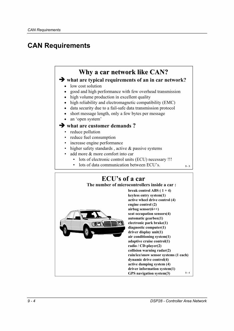
ECU’s of a carThe number of microcontrollers inside a car :
break control ABS ( 1 + 4)keyless entry system(1) active wheel drive control (4)engine control (2)airbag sensor(6++)seat occupation sensors(4)automatic gearbox(1)electronic park brake(1)diagnostic computer(1)driver display unit(1)air conditioning system(1)adaptive cruise control(1)radio / CD-player(2)collision warning radar(2)rain/ice/snow sensor systems (1 each)dynamic drive control(4)active damping system (4)driver information system(1)GPS navigation system(3)
9 - 9 - 33
Why a car network like CAN?Why a car network like CAN? what are typical requirements of an in car network?• low cost solution• good and high performance with few overhead transmission• high volume production in excellent quality • high reliability and electromagnetic compatibility (EMC)• data security due to a fail-safe data transmission protocol• short message length, only a few bytes per message• an ‘open system’ what are customer demands ?• reduce pollution• reduce fuel consumption• increase engine performance• higher safety standards , active & passive systems• add more & more comfort into car
• lots of electronic control units (ECU) necessary !!! • lots of data communication between ECU’s.

Basic CAN Features
DSP28 - Controller Area Network 9 - 5
Basic CAN Features
9 - 5
Features of CAN− developed by Robert Bosch GmbH, Stuttgart in 1987− licensed to most of the semiconductor manufacturers − meanwhile included in most of the microcontroller-families− today the most popular serial bus for automotive applications− competitors are : VAN ( France) , J1850 ( USA) and PALMNET ( Japan)− a lot of applications in automation & control ( low level field bus)
Features :• multi master bus access• random access with collision avoidance• short message length , at max. 8 Bytes per message• data rates 100KBPS to 1MBPS• short bus length , depending on data rate• self-synchronised bit coding technology• optimised EMC-behaviour• build in fault tolerance• physical transmission layers : RS485, ISO-high-
speed(differential voltage), ISO-low-speed (single voltage), fibre-optic, galvanic isolated
CAN does not use physical addresses to address stations. Each message is sent with an identifier that is recognized by the different nodes. The identifier has two functions – it is used for message filtering and for message priority. The identifier determines if a transmitted message will be received by CAN modules and determines the priority of the message when two or more nodes want to transmit at the same time.
The bus access procedure is a multi-master principle, all nodes are allowed to use CAN as a master node. One of the basic differences to Ethernet is the adoption of non-destructive bus arbitration in case of collisions, called “Carrier Sense Multiple Access with Collision Avoidance“(CSMA/CA). This procedure ensures that in case of an access conflict, the message with higher priority will not be delayed by this collision.
The physical length of the CAN is limited, depending on the baud rate. The data frame consists of a few bytes only (maximum 8), which increases the ability of the net to respond to new transmit requests. On the other hand, this feature makes CAN unsuitable for very high data throughputs, for example, for real time video processing.
There are several physical implementations of CAN, such as differential twisted pair (automotive class: CAN high speed), single line (automotive class: CAN low speed) or fibre optic CAN, for use in harsh environments.

CAN Implementation
9 - 6 DSP28 - Controller Area Network
CAN Implementation
9 - 6
Implementation / Classification of CANThe Implementation of CAN in Silicon
Don’t get confused !
Communication is identical for all implementations of CAN. However, there are two principal hardware implementations and two additional versions of data formats :
CAN-Implementation
Full-CANBASIC-CAN
There are two versions of how the CAN-module is implemented in silicon, called “BASIC” and “Full” – CAN. Almost all new processors with a built-in CAN module offer both modes of operation. BASIC-CAN as the only mode is normally used in cost sensitive applications.
9 - 7
BASIC-CAN and FULL-CAN- Close loop between MCU-core and CAN− only one transmit buffer− only two receive buffer− only one filter for incoming messages− Software routines are needed to select
between incoming messages
− provide a message server− extensive acceptance filtering on incoming
messages− user configurable mailboxes − mailbox memory area , size of mailbox areas
depends on manufacturer− advanced error recognition
BASIC-CAN
Full-CAN

CAN Data Frame
DSP28 - Controller Area Network 9 - 7
CAN Data Frame
9 - 8
The Data Format of CAN
• CAN-Version 2.0A• messages with 11-bit-
identifiers
• CAN-Version 2.0B • messages with 29-bit-
identifiers
==> Suitably configured, each implementation ( BASIC or FULL) can handle both standard and extended data formats.
Standard-CAN
Extended-CAN
The two versions of the data frame format allow the reception and transmission of standard frames and extended frames in a mixed physical set up, provided the silicon is able to handle both types simultaneously (CAN version 2.0A and 2.0B respectively).
9 - 9
The CAN Data Frame (cont.)
E O F + IF S1 0 b i ts
A C K2 b i ts
C R C1 5 b i t s
d a t a0 . ..8 b y te
D L C4 b i ts
r01 b i t
ID E1 b i t
R T R1 b i t
Id e n ti fi e r1 1 b i ts
s ta r t1 b i t
Identifier11 bits
s tart1 bit EOF + IFS
10 bits
ACK2 bits
CRC15 bits
data0...8 byte
DLC4 bits
r01 bit
r11bit
RTR1bitSRR
1bitIDE1bit
Identifier18bit
DATA-Frame CAN 2.0A ( 11-bit-identifier )
DATA-Frame CAN 2.0B ( 29-bit-identifier )

CAN Data Frame
9 - 8 DSP28 - Controller Area Network
9 - 10
The CAN Data Frame each data frame consists of four segments :
(1) arbitration-field :• denote the priority of the message• logical address of the message ( identifier )• Standard frame , CAN 2.0A : 11 bit-identifier • Extended frame ( CAN 2.0B ) : 29 bit-identifier
(2) data field :• up to 8 bytes per message , • a 0 byte message is also permitted
(3) CRC field:• cyclic redundancy check ; contains a checksum
generated by a CRC-polynomial(4) end of frame field:
• contains acknowledgement , error-messages, end of message
9 9 -- 1111
The CAN Data Frame (cont.) The CAN Data Frame (cont.) start bit (1 bit - dominant ): flag for the begin of a message; after idle-time falling-
edge to synchronise all transmittersidentifier (11 bit) : mark the name of the message and its priority ;the lower the value
the higher the priorityRTR (1 bit) : remote transmission request ; if RTR=1 ( recessive) no valid data’s
inside the frame - it is a request for receivers to send their messages IDE (1 bit) : Identifier Extension ; if IDE=1 then extended CAN-frame r0 (1 bit) :reservedCDL (4 bit) : data length code, code-length 9 to 15 are not permitted !data (0..8 byte ) : the data’s of the messageCRC (15 bit ) : cyclic redundancy code ; only to detect errors, no correction ;
hamming-distance 6 (up to 6 single bit errors )ACK (2 bit) : acknowledge ; each listener, which receive a message without errors
( including CRC !) has to transmit an acknowledge-bit in this time-slot !!!EOF (7 bit = 1 , recessive ) : end of frame ; intentional violation of the bit-stuff-
rule ; normally after five recessive bits one stuff-bit follows automaticallyIFS ( 3 bit = 1 recessive ) : inter frame space ; time space to copy a received
message from bus-handler into bufferExtended Frame only :SRR (1 bit = recessive) : substitute remote request ; substitution of the RTR-bit in
standard framesr1 (1 bit ): reserved
CAN Automotive Classes
DSP28 - Controller Area Network 9 - 9
CAN Automotive Classes
9 - 12
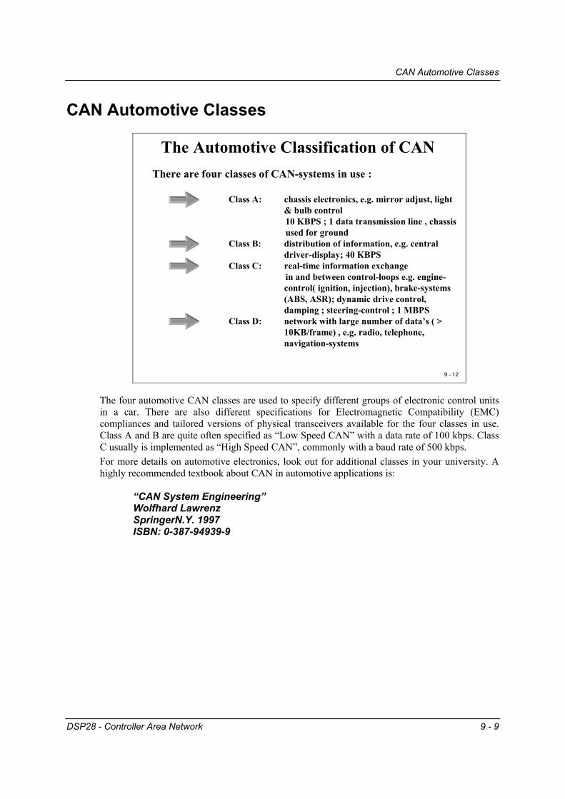
The Automotive Classification of CAN There are four classes of CAN-systems in use :
Class A: chassis electronics, e.g. mirror adjust, light & bulb control10 KBPS ; 1 data transmission line , chassis used for ground
Class B: distribution of information, e.g. central driver-display; 40 KBPS
Class C: real-time information exchange in and between control-loops e.g. engine-control( ignition, injection), brake-systems (ABS, ASR); dynamic drive control, damping ; steering-control ; 1 MBPS
Class D: network with large number of data’s ( > 10KB/frame) , e.g. radio, telephone, navigation-systems
The four automotive CAN classes are used to specify different groups of electronic control units in a car. There are also different specifications for Electromagnetic Compatibility (EMC) compliances and tailored versions of physical transceivers available for the four classes in use. Class A and B are quite often specified as “Low Speed CAN” with a data rate of 100 kbps. Class C usually is implemented as “High Speed CAN”, commonly with a baud rate of 500 kbps. For more details on automotive electronics, look out for additional classes in your university. A highly recommended textbook about CAN in automotive applications is:
“CAN System Engineering” Wolfhard Lawrenz SpringerN.Y. 1997 ISBN: 0-387-94939-9
ISO Standardization
9 - 10 DSP28 - Controller Area Network
ISO Standardization
9 - 13
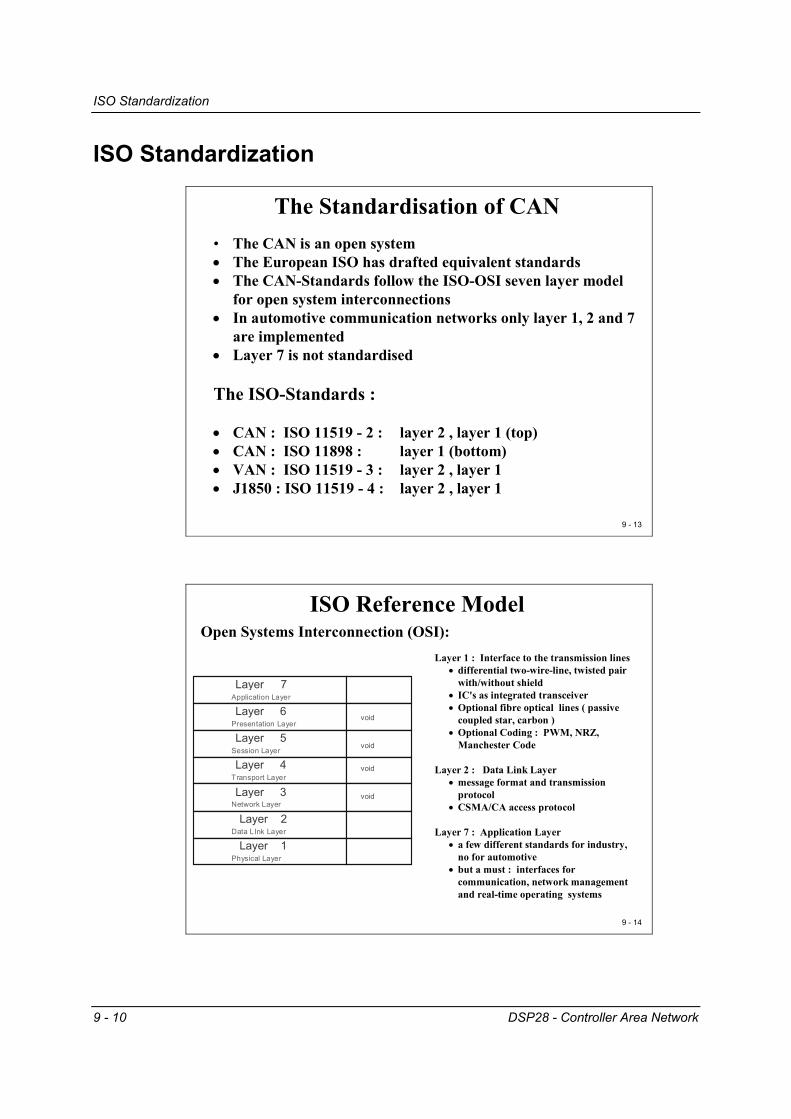
The Standardisation of CAN • The CAN is an open system• The European ISO has drafted equivalent standards• The CAN-Standards follow the ISO-OSI seven layer model
for open system interconnections • In automotive communication networks only layer 1, 2 and 7
are implemented• Layer 7 is not standardised
The ISO-Standards :
• CAN : ISO 11519 - 2 : layer 2 , layer 1 (top)• CAN : ISO 11898 : layer 1 (bottom)• VAN : ISO 11519 - 3 : layer 2 , layer 1• J1850 : ISO 11519 - 4 : layer 2 , layer 1
9 - 14
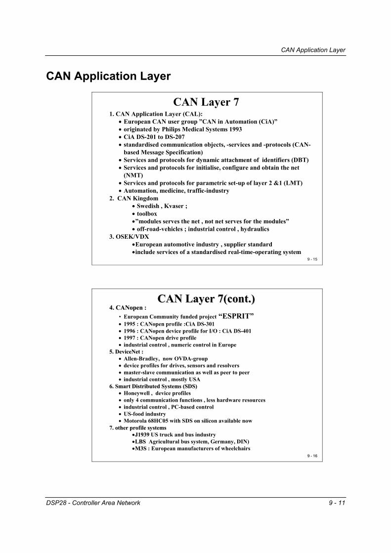
ISO Reference ModelOpen Systems Interconnection (OSI):
Layer 7
Layer 6
Layer 5
Layer 4
Layer 3
Layer 2
Layer 1
Application Layer
Presentation Layer
Session Layer
Transport Layer
Network Layer
Data LInk Layer
Physical Layer
void
void
void
void
Layer 1 : Interface to the transmission lines• differential two-wire-line, twisted pair
with/without shield• IC's as integrated transceiver• Optional fibre optical lines ( passive
coupled star, carbon )• Optional Coding : PWM, NRZ,
Manchester Code
Layer 2 : Data Link Layer• message format and transmission
protocol• CSMA/CA access protocol
Layer 7 : Application Layer • a few different standards for industry,
no for automotive• but a must : interfaces for
communication, network management and real-time operating systems
CAN Application Layer
DSP28 - Controller Area Network 9 - 11
CAN Application Layer
9 - 15
CAN Layer 71. CAN Application Layer (CAL):
• European CAN user group ”CAN in Automation (CiA)”• originated by Philips Medical Systems 1993• CiA DS-201 to DS-207• standardised communication objects, -services and -protocols (CAN-
based Message Specification)• Services and protocols for dynamic attachment of identifiers (DBT)• Services and protocols for initialise, configure and obtain the net
(NMT)• Services and protocols for parametric set-up of layer 2 &1 (LMT)• Automation, medicine, traffic-industry
2. CAN Kingdom• Swedish , Kvaser ; • toolbox•”modules serves the net , not net serves for the modules”• off-road-vehicles ; industrial control , hydraulics
3. OSEK/VDX•European automotive industry , supplier standard•include services of a standardised real-time-operating system
9 9 -- 1616
CAN Layer 7(cont.)CAN Layer 7(cont.)4. 4. CANopenCANopen : :
• European Community funded project “ESPRIT” • 1995 : CANopen profile :CiA DS-301• 1996 : CANopen device profile for I/O : CiA DS-401• 1997 : CANopen drive profile• industrial control , numeric control in Europe
5. 5. DeviceNetDeviceNet ::• Allen-Bradley, now OVDA-group• device profiles for drives, sensors and resolvers• master-slave communication as well as peer to peer• industrial control , mostly USA
6. Smart Distributed Systems (SDS)6. Smart Distributed Systems (SDS)• Honeywell , device profiles• only 4 communication functions , less hardware resources• industrial control , PC-based control• US-food industry• Motorola 68HC05 with SDS on silicon available now
7. other profile systems7. other profile systems••J1939 J1939 US truck and bus industry••LBS LBS Agricultural bus system, Germany, DIN)••M3SM3S : European manufacturers of wheelchairs
CAN Bus Arbitration – CSMA/CA
9 - 12 DSP28 - Controller Area Network
CAN Bus Arbitration – CSMA/CA
9 - 17
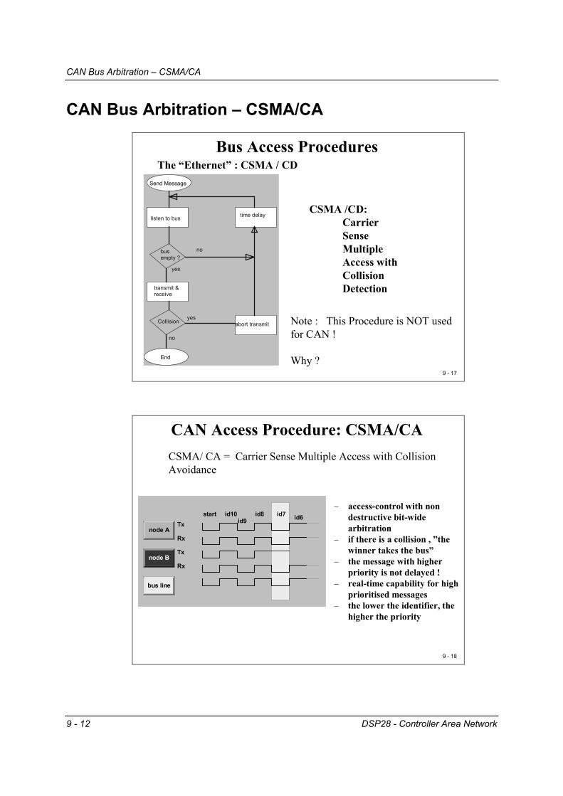
Bus Access ProceduresThe “Ethernet” : CSMA / CD
Send Message
End
listen to bus
busempty ?
transmit &receive
Collision abort transmit
time delay
no
yes
yes
no
CSMA /CD:Carrier SenseMultipleAccess withCollision Detection
Note : This Procedure is NOT used for CAN !
Why ?
9 - 18
CAN Access Procedure: CSMA/CA
node A
node B
bus line
Tx
Rx
Tx
Rx
start id10id9
id8 id7 id6
CSMA/ CA = Carrier Sense Multiple Access with Collision Avoidance
− access-control with non destructive bit-wide arbitration
− if there is a collision , ”the winner takes the bus”
− the message with higher priority is not delayed !
− real-time capability for high prioritised messages
− the lower the identifier, the higher the priority

CAN Bus Arbitration – CSMA/CA
DSP28 - Controller Area Network 9 - 13
9 - 19
CSMA/CA (cont.)CSMA / CA ="bit - wide arbitration during transmission with simultaneous receiving and comparing of the transmitted message" means :
• if there is a collision within the arbitration-field, only the node with the lower priority cancels its transmission.
• The node with the highest priority continues with the transmission of the message.
node 1 node 2 node 3
high : reccessive
low : dominant
node 1 node 2 node 3 bus high high high high high low high low low low high low
Vcc
R
As you can see from the previous slide the arbitration procedure at a physical level is quite sim-ple: it is a “wired-AND” principle. Only if all 3 node voltages (node 1, node2 or node3) are equal to 1 (recessive), the bus voltage stays at Vcc (recessive). If only one node voltage is switched to 0 (dominant), the bus voltage is forced to the dominant state (0). The beauty of CAN is that the message with highest priority is not delayed at all in case of a col-lision. For the message with highest priority, we can determine the worst-case response time for a data transmission. For messages with other priorities, to calculate the worst-case response time is a little bit more complex task. It could be done by applying a so-called “time dilatation formula for non-interruptible systems”:
HARTER, P.K: “Response Times in level structured systems” Techn. Re-port, Univ. of Colorado, 1991
In detail, the hardware structure of a CAN-transceiver is more complex. Due to the principle of CAN-transmissions as a “broadcast” type of data communication, all CAN-modules are forced to “listen” to the bus all the time. This also includes the arbitration phase of a data frame. It is very likely that a CAN-module might lose the arbitration procedure. In this case, it is necessary for this particular module to switch into receive mode immediately. This requires every transceiver to provide the actual bus voltage status permanently to the CAN-module.
jihpj j
ini
iini C
TCR
BCR ∗
−++= ∑
∈
+
)(max
1

High Speed CAN
9 - 14 DSP28 - Controller Area Network
High Speed CAN
9 - 20
CAN Physical LayersCAN - High - Speed ( ISO 11898 ) :
node 1 node 30
120Ohm
120
Ohm
CAN_H
CAN_L
V o lta g e
tim e
2 ,5 V
3 ,5 V
1 ,5 V
C A N _ H
C A N _ L
re c e s s iv e d o m in a n t re c e s s ic v e
C A N h ig h -s p e e d , n o m in a l b u s le v e ls
To generate the voltage levels for the differential voltage transmission according to CAN High Speed we need an additional transceiver device, e.g. the SN65HVD23x.
9 - 21
CAN High speed Node
DSP with on-chipCAN module
CAN Transceiver
CAN BUS
TxdRxd
CAN_L
CAN_H
SN65HVD23X

CAN Error Management
DSP28 - Controller Area Network 9 - 15
CAN Error Management
9 - 22
CAN Error & Exception Management
errorhandling
errordetection
errormanaging
errorlimitation
How does it work ?- most of errors should be detected and self-corrected by the CAN-Chip
itself - automatic notification to all other nodes, that an error has been seen :
Error-Frame = deliberate violation of code-law’s )( 6-bit dominant = passive error frame )( 12-bit dominant = active error frame )
- all nodes have to cancel the last message they have received - transmission is repeated automatically by the bus - handler
9 9 -- 2323
CAN Error Recognition CAN Error Recognition
•• BitBit--ErrorErrorthe transmitted bit doesn’t read back with the same digital level ( except arbitration and acknowledge- slot )
•• BitBit--StuffStuff--ErrorErrormore than 5 continuous bits read back with the same digital level ( except ‘end of frame’-part of the message )
•• CRCCRC--ErrorErrorthe received CRC-sum doesn’t match with the calculated sum
•• FormatFormat--ErrorErrorViolation of the data-format of the message , e.g.: CRC-delimiter is not recessive or violation of the ‘end -of-frame’-field
•• AcknowledgementAcknowledgement--ErrorErrortransmitter receives no dominant bit during the acknowledgement slot, i.e. the message was not received by any node.

CAN Error Management
9 - 16 DSP28 - Controller Area Network
9 - 24
CAN Error Sequence error
handling
errordetection
errormanaging
errorlimitation
After detection of an error by a node every other node receives a particular frame , the Error -Frame : This is the violation of the stuff-bit-rule by transmission of at least 6 dominant bits.The Error-Frame causes all other nodes to recognise an Error Status of the bus.
• error is detected• error-frame will be transmitted by all nodes, which have detected
this error• The last message received will be cancelled by all nodes• Internal hardware error-counters will be increased• The original message will be transmitted again.
Error Management Sequence :
9 - 25
CAN Error Status
errorhandling
errordetection
errormanaging
errorlimitation
erroractive
error passive
busoff
* Purpose: avoid persistent disturbances of the CAN by switching off defective nodes
* three Error States :
Error Active : normal mode, messages will be received and transmitted. In case of error an active error frame will be transmitted
Error Passive : after detection of a fixed number of errors , the node reaches this state. messages will be received and transmitted, in case of error the node sends a passive error frame.
Bus Off : the node is separated from CAN , neither transmission nor receive of messages is allowed, node is not able to transmit error frame’s .leaving this state is only possible by reset !

CAN Error Management
DSP28 - Controller Area Network 9 - 17
9 - 26
CAN Error Counter
error passive
error active
bus off
REC <127andTEC <=127
REC >127 or127<TEC<255
TEC > 255
'reset' or 'init node'
• transitions will be carried out automatically by the CAN-chip
• states are managed by 2 Error Counters :Receive Error Counter (REC)Transmit Error Counter (TEC)
• Possible situations :a) a transmitter recognises an error:
TEC:=TEC + 8b) a receiver sees an error : REC:=REC + 1c) a receiver sees an error, after transmitting an
error frame: REC:=REC + 8d) if an ‘error active’-node find’s a bit-stuff-
error during transmission of an error frame:TEC:=TEC+ 1
e) successful transmission:TEC:=TEC - 1
f) successful receive :REC:=REC - 1
State - Diagram :
C28x CAN Module
9 - 18 DSP28 - Controller Area Network
C28x CAN Module
9 9 -- 2727
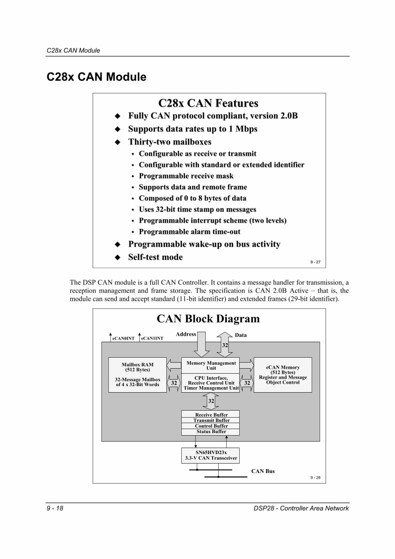
C28x CAN FeaturesC28x CAN FeaturesFully CAN protocol compliant, version 2.0BFully CAN protocol compliant, version 2.0BSupports data rates up to 1 MbpsSupports data rates up to 1 MbpsThirtyThirty--two mailboxestwo mailboxes
Configurable as receive or transmitConfigurable as receive or transmitConfigurable with standard or extended identifierConfigurable with standard or extended identifierProgrammable receive maskProgrammable receive maskSupports data and remote frameSupports data and remote frameComposed of 0 to 8 bytes of dataComposed of 0 to 8 bytes of dataUses 32Uses 32--bit time stamp on messagesbit time stamp on messagesProgrammable interrupt scheme (two levels)Programmable interrupt scheme (two levels)Programmable alarm timeProgrammable alarm time--outout
Programmable wakeProgrammable wake--up on bus activityup on bus activitySelfSelf--test mode test mode
The DSP CAN module is a full CAN Controller. It contains a message handler for transmission, a reception management and frame storage. The specification is CAN 2.0B Active – that is, the module can send and accept standard (11-bit identifier) and extended frames (29-bit identifier).
9 - 28
CAN Block Diagram
Memory ManagementUnit
CPU Interface,Receive Control Unit
Timer Management Unit
eCAN Memory(512 Bytes)
Register and MessageObject Control
Mailbox RAM(512 Bytes)
32-Message Mailboxof 4 x 32-Bit Words 32 32
Receive BufferTransmit BufferControl BufferStatus Buffer
SN65HVD23x3.3-V CAN Transceiver
. . CAN Bus
32
32
DataAddresseCAN0INT eCAN1INT
C28x Programming Interface
DSP28 - Controller Area Network 9 - 19
C28x Programming Interface
9 - 29
CAN Memory
Data Space
CAN0x00 6000
0x00 0000
0x 3F FFFF
0x00 61FF
6080
6040
61FF
Control andStatus Register
Message Object
Time Stamps
Mailbox 0Mailbox 1
Mailbox 31
Local Acceptance
Masks
Message Object
Time Out
60C0
61086100
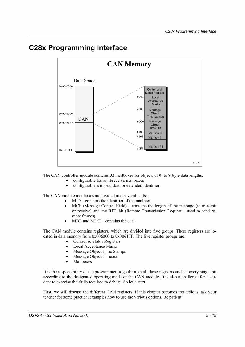
The CAN controller module contains 32 mailboxes for objects of 0- to 8-byte data lengths:
• configurable transmit/receive mailboxes • configurable with standard or extended identifier
The CAN module mailboxes are divided into several parts:
• MID – contains the identifier of the mailbox • MCF (Message Control Field) – contains the length of the message (to transmit
or receive) and the RTR bit (Remote Transmission Request – used to send re-mote frames)
• MDL and MDH – contains the data The CAN module contains registers, which are divided into five groups. These registers are lo-cated in data memory from 0x006000 to 0x0061FF. The five register groups are:
• Control & Status Registers • Local Acceptance Masks • Message Object Time Stamps • Message Object Timeout • Mailboxes
It is the responsibility of the programmer to go through all those registers and set every single bit according to the designated operating mode of the CAN module. It is also a challenge for a stu-dent to exercise the skills required to debug. So let’s start! First, we will discuss the different CAN registers. If this chapter becomes too tedious, ask your teacher for some practical examples how to use the various options. Be patient!

C28x Programming Interface
9 - 20 DSP28 - Controller Area Network
CAN Register Map
9 - 30
CAN Control & Status Register
6000 CANMECANMD6002
6004 CANTRSCANTRR6006
6008 CANTACANAA600A
600C CANRMPCANRML600E
6010 CANRFPCANGAM6012
6014 CANMCCANBTC6016
6018 CANESCANTEC601A
601C CANREC
6020 CANGIMCANGIF16022
6024 CANMIMCANMIL6026
6028 CANOPCCANTIOC602A
602C CANRIOC602E CANLNT
CANTOC60306032 CANTOS
CANGIF0601E
31 0 31 0
6034 reservedreserved6036
6038 reservedreserved603A
603C reservedreserved603E
Mailbox Enable – CANME Mailbox Direction - CANMD
9 9 -- 3131
CAN Mailbox Enable Register (CANME) – 0x006000
15
1631
CANME[15:0]
CANME[31:16]
0
Mailbox Enable Bits0 = corresponding mailbox is disabled1 = The corresponding mailbox is enabled. A mailbox must be disabled before
writing to the contents of any mailbox identifier field.
CAN Mailbox Direction Register (CANMD) – 0x006002
15
1631
CANMD[15:0]
CANMD[31:16]
0
Mailbox Direction Bits0 = corresponding mailbox is defined as a transmit mailbox.1 = corresponding mailbox is defined as a receive mailbox.

C28x Programming Interface
DSP28 - Controller Area Network 9 - 21
Transmit Request Set & Reset - CANTRS / CANTRR
9 9 -- 3232
CAN Transmission Request Set Register (CANTRS) – 0x006004
15
1631
CANTRS[15:0]
CANTRS[31:16]
0
Mailbox Transmission Request Set Bits (TRS)0 = no operation. NOTE: Bit will be cleared by CAN-Module logic after successful transmission.1 = Start of transmission of corresponding mailbox. Set to 1 by user software;
OR by CAN –logic in case of a Remote Transmit Request.
CAN Transmission Request Reset Register (CANTRR) – 0x006006
15
1631
CANTRR[15:0]
CANTRR[31:16]
0
Mailbox Transmission Reset Request Bits (TRR)0 = no operation.1 = setting TRRn cancels a transmission request, if not currently being processed.
Transmit Acknowledge - CANTA
9 9 -- 3333
CAN Transmission Acknowledge Register (CANTA) – 0x006008
15
1631
CANTA[15:0]
CANTA[31:16]
0
Mailbox Transmission Acknowledge Bits (TA)0 = the message is not sent.1 = if the message of mailbox n is sent successfully, the bit n of this register is set. Note: To reset a TA bit by software: write a ‘1’ into it!!
CAN Abort Acknowledge Request Register (CANAA) – 0x00600A
15
1631
CANAA[15:0]
CANAA[31:16]
0
Mailbox Abort Acknowledge Bits (AA)0 = The transmission is not aborted.1 = The transmission of mailbox n is aborted.Note: To reset a AA bit by software: write a ‘1’ into it!!

C28x Programming Interface
9 - 22 DSP28 - Controller Area Network
Receive Message Pending - CANRMP
9 - 34
CAN Receive Message Pending Register (CANRMP) – 0x00600C
15
1631
CANRMP[15:0]
CANRMP[31:16]
0
Mailbox Receive Message Pending Bits (RMP)0 = the mailbox does not contain a message.1 = the mailbox contains a valid message. Note: To reset a RMP bit by software: write a ‘1’ into it!!
CAN Receive Message Lost Register (CANRML) – 0x00600E
15
1631
CANRML[15:0]
CANRML[31:16]
0
Mailbox Receive Message Lost Bits (RML)0 = no message was lost.1 = an old unread message has been overwritten by a new one in that mailbox.Note: To reset a RML bit by software: write a ‘1’ into it!!
Remote Frame Pending - CANRFP
9 - 35
CAN Remote Frame Pending Register (CANRFP) – 0x006010
15
1631
CANRFP[15:0]
CANRFP[31:16]
0
Mailbox Remote Frame Pending Bits (RFP)0 = no remote frame request was received.1 = a remote frame request was received by the CAN module. Note: To reset a RFP bit by software: write a ‘1’ into the corresponding TRR bit!!

C28x Programming Interface
DSP28 - Controller Area Network 9 - 23
Global Acceptance Mask - CANGAM
9 - 36
CAN Global Acceptance Mask Register (CANGAM) – 0x006012
15
1631
CANGAM[15:0]
CANGAM[28:16]
0
Acceptance Mask Identifier Bit (AMI)0 = the identifier extension bit in the mailbox determines which messages shall be received.
Filtering is not applicable.1 = standard and extended frames can be received. In case of an extended frame all 29 bits of the identifier
and all 29 bits of the GAM are used for the filter. In case of a standard frame only bits 28-18 of the identifierand the GAM are used for the filter.
Note: The IDE bit of a receive mailbox is a “don’t care” and is overwritten by the IDE bit of the transmitted message.
AMI reserved
30-29 28
Note : This Register is used in SCC mode only for mailboxes 6 to 15, if the AME bit (MID.30)of the corresponding mailbox is set. It is a “don’t care” for HECC – Mode!
Global Acceptance Mask (GAM)0 = bit position must match the corresponding bit in register CANMIDn. 1 = bit position of the incoming identifier is a “don’t’ care”. Note: To reset a RFP bit by software: write a ‘1’ into the corresponding TRR bit!!

C28x Programming Interface
9 - 24 DSP28 - Controller Area Network
Master Control Register - CANMC
9 - 37
CAN Master Control Register (CANMC) – 0x006014
15
1631
reserved
0
MBCC MBNR
Mailbox Timestamp counter clear (MBCC)0 = no operation 1 = timestamp counter is reset to 0 after a successful transmission or reception of mailbox 16.
ABOCDRWUBADBOPDRCCRSCBTCC SRESSTM
414 13 12 11 10 9 8 7 6 5
Timestamp counter MSB clear (TCC)0 = no operation 1 = timestamp counter MSB is reset to 0
SCC Compatibility bit (SCB)0 = SCC mode 1 = high end CAN (HECC) mode
Change Configuration Request (CCR)0 = software requests normal operation 1 = software requests write access to CANBTC, CANGAM, LAM[0] and LAM[3].
A request is granted by the CAN module with flag CCE ( CANES) = 1.NOTE: SCC Mode only !
9 - 38
CAN Master Control Register (CANMC) – 0x006014 (cont.)
15 0
MBCC MBNRABOCDRWUBADBOPDRCCRSCBTCC SRESSTM
414 13 12 11 10 9 8 7 6 5
Data Byte Order (DBO) in Mailbox RegistersMDH[31:0] and MDL[31:0]0 = MDH[31:0] : Byte 4,5,6,7 ; MDL[31:0] : Byte 0,1,2,3 1 = MDH[31:0] : Byte 7,6,5,4 ; MDL[31:0] : Byte 3,2,1,0
Wake up on bus activity (WUBA)0 = Module leaves power down only
after writing a 0 to PDR 1 = Module leaves power down on
any bus activity
Change data field request (CDR)0 = normal operation 1 = software requests access to the data field in 2MBNR”. NOTE: software must clear this bit after access is done.
Auto bus on (ABO)0 = “bus off’ state is permanent. 1 = “bus off” state is left into “bus on”
after 128*11 recessive bits have been received.
Self Test Mode (STM)0 = normal mode 1 = Module generates its own ACK
Software Reset(SRES)0 = no effect 1 = CAN Module reset
Mailbox Number(MBNR)Number , used for CDR
Power Down Mode Request (PDR)0 = normal operation 1 = power down mode is requested.NOTE: bit is automatically cleared upon wakeup from power down!

CAN Bit - Timing
DSP28 - Controller Area Network 9 - 25
CAN Bit - Timing
9 - 39
CAN Bit-Timing ConfigurationCAN protocol specification splits the nominal bit time into four different time segments:
SYNC_SEGUsed to synchronize nodesLength : always 1 Time Quantum (TQ)
PROP_SEGCompensation time for the physical delay times within the netTwice the sum of the signal’s propagation time on the bus line, the input comparator delay and the output driver delay.Programmable from 1 to 8 TQ
PHASE_SEG1Compensation for positive edge phase shiftProgrammable from 1 to 8 TQ
PHASE_SEG2Compensation time for negative edge phase shiftProgrammable from 2 to 8 TQ
9 - 40
CAN Bit-Timing Configuration
tseg1 : PROP_SEG + PHASE_SEG1tseg2 : PHASE_SEG2TQ : SYNCSEG
CAN Nominal Bit Time = TQ + tseg1 + tseg2
CAN Nominal Bit TimeSYNCSEG
sjwsjw
tseg2tseg1
TQ
Sample PointTransmit Point

CAN Bit - Timing
9 - 26 DSP28 - Controller Area Network
9 - 41
CAN Bit-Timing Configuration
According to the CAN – Standard the following bit timing rules must be fulfilled:
tseg1 ≥ tseg23/BRP tseg1 16 TQ3/BRP tseg2 8 TQ1 TQ sjw MIN[ 4*TQ , tseg2]
BRP ≥ 5 ( if three sample mode is used)
Bit-Timing Configuration - CANBTC
9 - 42
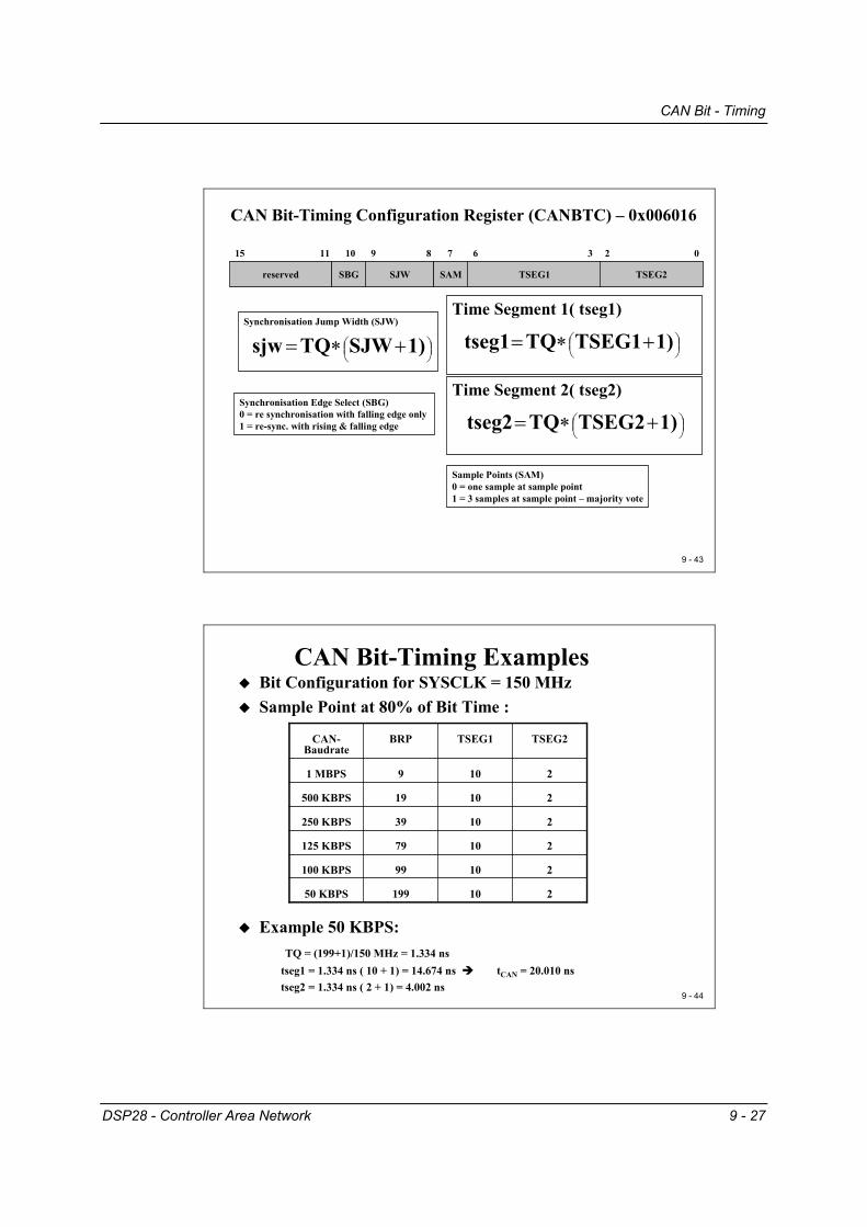
CAN Bit-Timing Configuration Register (CANBTC) – 0x006016
Baud Rate Prescaler (BRP)Defines the Time Quantum (TQ):
31
reserved BRP.2BRP.3BRP.4BRP.5 BRP.0BRP.1
16
BRP.7 BRP.6
2324
SYSCLK1BRPTQ +=
Note: with an external clock of 30MHz and a PLL * 5:SYSCLK = 150MHz
CAN Bit - Timing
DSP28 - Controller Area Network 9 - 27
9 - 43
Synchronisation Jump Width (SJW)
+∗= 1)SJWTQsjw
CAN Bit-Timing Configuration Register (CANBTC) – 0x006016
Time Segment 1( tseg1)
+∗= 1)TSEG1TQtseg1
15
reserved TSEG1SJW TSEG2
0
SAMSBG
78 23691011
Time Segment 2( tseg2)
+∗= 1)TSEG2TQtseg2
Sample Points (SAM)0 = one sample at sample point 1 = 3 samples at sample point – majority vote
Synchronisation Edge Select (SBG)0 = re synchronisation with falling edge only 1 = re-sync. with rising & falling edge
9 - 44
CAN Bit-Timing ExamplesBit Configuration for SYSCLK = 150 MHzSample Point at 80% of Bit Time :
Example 50 KBPS: TQ = (199+1)/150 MHz = 1.334 ns
tseg1 = 1.334 ns ( 10 + 1) = 14.674 ns tCAN = 20.010 ns tseg2 = 1.334 ns ( 2 + 1) = 4.002 ns
21019950 KBPS
21099100 KBPS
21079125 KBPS
21039250 KBPS
21019500 KBPS
21091 MBPS
TSEG2TSEG1BRPCAN-Baudrate

CAN Error Register
9 - 28 DSP28 - Controller Area Network
CAN Error Register
Error and Status - CANES
9 - 45
CAN Error and Status Register (CANES) – 0x006018
Warning Status (EW)0 = values of both error counters are less than 961 = one error counter has reached 96
Error Passive State (EP)0 = CAN is in Error Active Mode1 = CAN is in Error Passive Mode
31
reserved BOACKESECRCE EWEP
16
BE SA1
2324 171819202122
FE
Bus Off State (BO)0 = normal operation1 = CANTEC has reached the limit of 256. Module
has been switched of the bus.
Stuff Bit Error (SE)0 = normal operation1 = a stuff bit error has occurred.
Acknowledgement Error (ACKE)0 = normal operation1 = CAN module has not received an ACK.
Cyclic Redundancy Check Error (CRCE)0 = normal operation1 = a wrong CRC was received.
Stuck at dominant Error (SA1)0 = The CAN module detected a recessive bit1 = The CAN module never detected a recessive bit.
Bit Error (BE)0 = no bit error detected1 = a received bit does not match a transmitted bit
(outside of the arbitration field).
Form Error (FE)0 = normal operation1 = one of the fixed form bit fields of a message was wrong.
9 - 46
CAN Error and Status Register (CANES) – 0x006018
Transmit Mode (TM)0 = CAN protocol kernel is not transmitting a message.1 = CAN protocol kernel is transmitting a message.
Receive Mode (RM)0 = CAN protocol kernel is not receiving a message.1 = CAN protocol kernel is receiving a message.
15
reserved Res.PDACCESMA TMRM
0123456
Power Down Mode Acknowledge (PDA)0 = normal operation1 = CAN module has entered power down mode.
Change Configuration Enable (CCE)0 = CPU is denied write access into
configuration registers.1 = CPU has write access into
configuration registers.
Suspend Mode Acknowledge (SMA)0 = normal operation1 = CAN module has entered suspend mode.Note: Suspend mode is activated by the debugger when the DSP is not in run mode.
CAN Error Register
DSP28 - Controller Area Network 9 - 29
Transmit & Receive Error Counter - CANTEC / CANREC
9 - 47
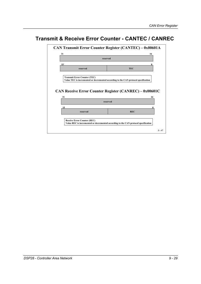
CAN Transmit Error Counter Register (CANTEC) – 0x00601A
CAN Receive Error Counter Register (CANREC) – 0x00601C
15
1631
reserved
0
Transmit Error Counter (TEC)Value TEC is incremented or decremented according to the CAN protocol specification
reserved TEC
15
1631
reserved
0
Receive Error Counter (REC)Value REC is incremented or decremented according to the CAN protocol specification
reserved REC

CAN Interrupt Register
9 - 30 DSP28 - Controller Area Network
CAN Interrupt Register
Global Interrupt Mask - CANGIM
9 - 48
CAN Global Interrupt Mask Register (CANGIM) – 0x006020
Global Interrupt Level (GIL)For Interrupts TCOF,WDIF,WUIF,BOIF and WLIF0 = mapped into HECC_INT_REQ[0] line – GIF01 = mapped into HECC_INT_REQ[1] line – GIF1
Interrupt Mask Bits:
MTOM = Mailbox Timeout MaskTCOM = Timestamp Counter Overflow MaskAAM = Abort Acknowledge Interrupt MaskWDIM = Write Denied Interrupt MaskWUIM = Wake-up Interrupt MaskRMLIM = Receive message lost Interrupt MaskBOIM = Bus Off Interrupt MaskEPIM = Error Passive Interrupt MaskWLIM = Warning level Interrupt Mask
Interrupt Mask Bits 0 = Interrupt disabled1 = Interrupt enabled
15
1631
reserved
0
Res. reserved GILWLIMEPIMBOIMRMLIMWUIMWDIMAAM I0ENI1EN
114 13 12 11 10 9 8 7 3 2
TCOMMTOM
1718
Interrupt 1 Enable (I1EN)0 = HECC_INT_REQ[1] line is disabled1 = HECC_INT_REQ[1] line is enabled
Interrupt 0 Enable (I0EN)0 = HECC_INT_REQ[0] line is disabled1 = HECC_INT_REQ[0] line is enabled
CAN Interrupt Register
DSP28 - Controller Area Network 9 - 31
Global Interrupt 0 Flag – CANGIF0
9 - 49
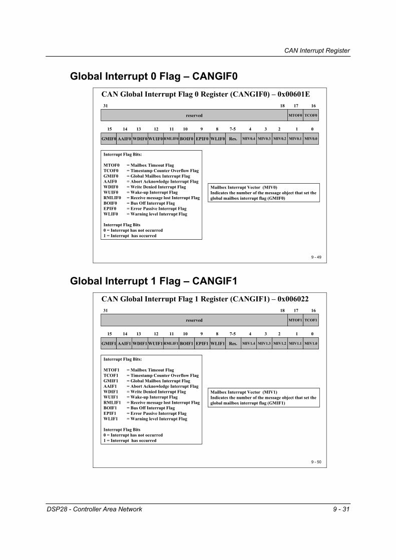
CAN Global Interrupt Flag 0 Register (CANGIF0) – 0x00601E
Mailbox Interrupt Vector (MIV0)Indicates the number of the message object that set the global mailbox interrupt flag (GMIF0)
Interrupt Flag Bits:
MTOF0 = Mailbox Timeout FlagTCOF0 = Timestamp Counter Overflow FlagGMIF0 = Global Mailbox Interrupt FlagAAIF0 = Abort Acknowledge Interrupt FlagWDIF0 = Write Denied Interrupt FlagWUIF0 = Wake-up Interrupt FlagRMLIF0 = Receive message lost Interrupt FlagBOIF0 = Bus Off Interrupt FlagEPIF0 = Error Passive Interrupt FlagWLIF0 = Warning level Interrupt Flag
Interrupt Flag Bits 0 = Interrupt has not occurred1 = Interrupt has occurred
15
1631
reserved
0
GMIF0 Res. MIV0.2WLIF0EPIF0BOIF0RMLIF0WUIF0WDIF0AAIF0 MIV0.0MIV0.1
114 13 12 11 10 9 8 7-5 3 2
TCOF0MTOF0
1718
MIV0.4 MIV0.3
4
Global Interrupt 1 Flag – CANGIF1
9 - 50
CAN Global Interrupt Flag 1 Register (CANGIF1) – 0x006022
Mailbox Interrupt Vector (MIV1)Indicates the number of the message object that set the global mailbox interrupt flag (GMIF1)
Interrupt Flag Bits:
MTOF1 = Mailbox Timeout FlagTCOF1 = Timestamp Counter Overflow FlagGMIF1 = Global Mailbox Interrupt FlagAAIF1 = Abort Acknowledge Interrupt FlagWDIF1 = Write Denied Interrupt FlagWUIF1 = Wake-up Interrupt FlagRMLIF1 = Receive message lost Interrupt FlagBOIF1 = Bus Off Interrupt FlagEPIF1 = Error Passive Interrupt FlagWLIF1 = Warning level Interrupt Flag
Interrupt Flag Bits 0 = Interrupt has not occurred1 = Interrupt has occurred
15
1631
reserved
0
GMIF1 Res. MIV1.2WLIF1EPIF1BOIF1RMLIF1WUIF1WDIF1AAIF1 MIV1.0MIV1.1
114 13 12 11 10 9 8 7-5 3 2
TCOF1MTOF1
1718
MIV1.4 MIV1.3
4
CAN Interrupt Register
9 - 32 DSP28 - Controller Area Network
Mailbox Interrupt Mask - CANMIM
9 - 51
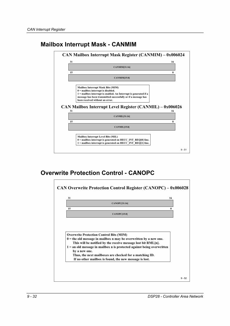
CAN Mailbox Interrupt Mask Register (CANMIM) – 0x006024
15
1631
CANMIM[15:0]
CANMIM[31:16]
0
Mailbox Interrupt Mask Bits (MIM)0 = mailbox interrupt is disabled.1 = mailbox interrupt is enabled. An Interrupt is generated if amessage has been transmitted successfully or if a message has been received without an error.
CAN Mailbox Interrupt Level Register (CANMIL) – 0x006026
15
1631
CANMIL[15:0]
CANMIL[31:16]
0
Mailbox Interrupt Level Bits (MIL)0 = mailbox interrupt is generated on HECC_INT_REQ[0] line.1 = mailbox interrupt is generated on HECC_INT_REQ[1] line.
Overwrite Protection Control - CANOPC
9 9 -- 5252
CAN Overwrite Protection Control Register (CANOPC) – 0x006028
15
1631
CANOPC[15:0]
CANOPC[31:16]
0
Overwrite Protection Control Bits (MIM)0 = the old message in mailbox n may be overwritten by a new one.
This will be notified by the receive message lost bit RML[n].1 = an old message in mailbox n is protected against being overwritten
by a new one. Thus, the next mailboxes are checked for a matching ID. If no other mailbox is found, the new message is lost.

CAN Interrupt Register
DSP28 - Controller Area Network 9 - 33
Transmit I/O Control - CANTIOC
9 - 53
CAN I/O Control Register (CANTIOC) – 0x00602A
TXFUNC0 = CANTX pin is a normal I/O pin.1 = CANTX is used for CAN transmit functions.
15
1631
reserved
reserved
0
TXINTXFUNC TXDIR TXOUT
2 13
TXDIR0 = CANTX pin is an input pin if configured as a normal I/O pin.1 = CANTX pin is an output pin if configured as a normal I/O pin.
TXOUTOutput value for CANTX pin, if configured as normal output pin
TXIN0 = Logic 0 present on pin CANTX.1 = Logic 1 present on pin CANTX.
Receive I/O Control - CANRIOC
9 - 54
CAN I/O Control Register (CANRIOC) – 0x00602C
RXFUNC0 = CANRX pin is a normal I/O pin.1 = CANRX is used for CAN receive functions.
15
1631
reserved
reserved
0
RXINRXFUNC RXDIR RXOUT
2 13
RXDIR0 = CANRX pin is an input pin if configured as a normal I/O pin.1 = CANRX pin is an output pin if configured as a normal I/O pin.
RXOUTOutput value for CANRX pin, if configured as normal output pin
RXIN0 = Logic 0 present on pin CANRX.1 = Logic 1 present on pin CANRX.
Alarm / Time Out Register
9 - 34 DSP28 - Controller Area Network
Alarm / Time Out Register
Local Network Time - CANLNT
9 - 55
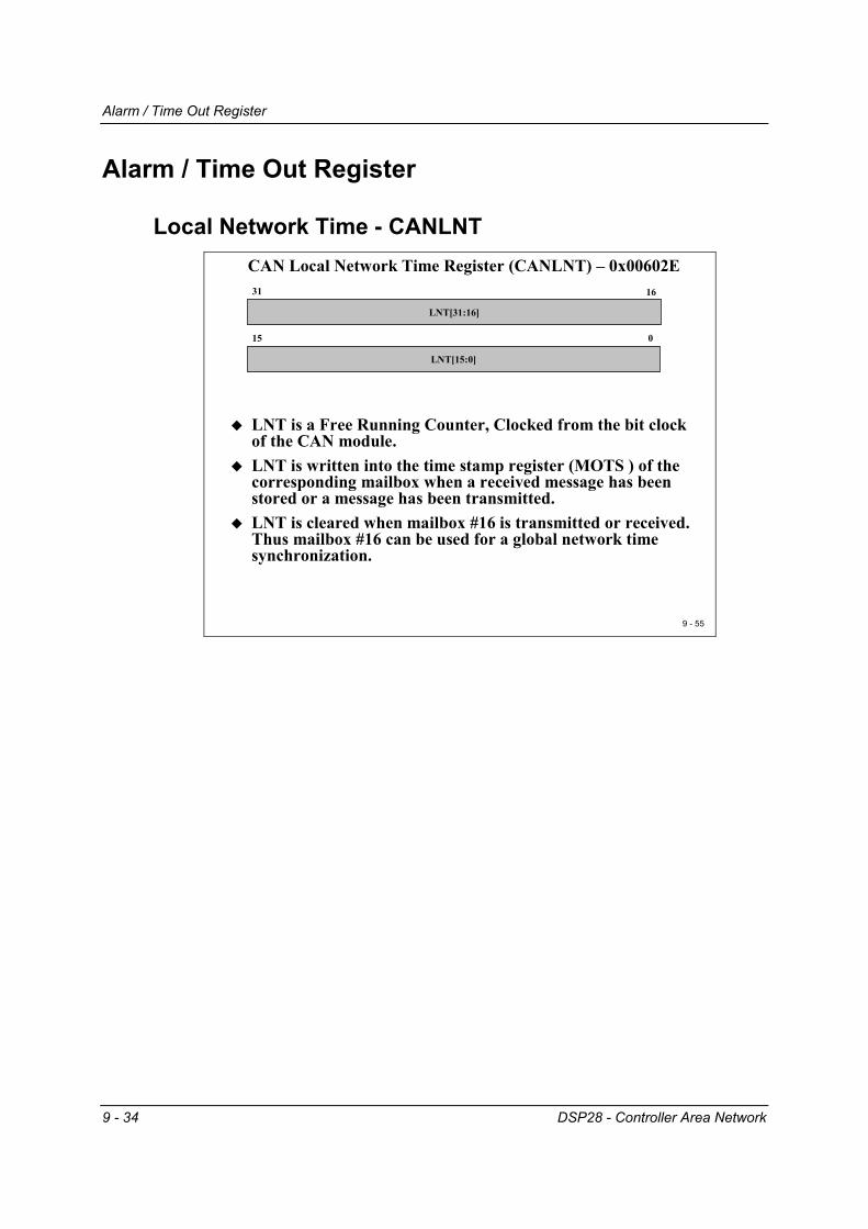
CAN Local Network Time Register (CANLNT) – 0x00602E
15
1631
LNT[15:0]
LNT[31:16]
0
LNT is a Free Running Counter, Clocked from the bit clock of the CAN module.LNT is written into the time stamp register (MOTS ) of the corresponding mailbox when a received message has been stored or a message has been transmitted.LNT is cleared when mailbox #16 is transmitted or received. Thus mailbox #16 can be used for a global network time synchronization.

Alarm / Time Out Register
DSP28 - Controller Area Network 9 - 35
Time Out Control - CANTIOC
9 - 56
CAN Time Out Control Register (CANTOC) – 0x006030
31
031
TOS[31:0]
TOC[31:0]
0
Time Out Control Bits (TOC)0 = Time Out function is disabled for mailbox n.1 = Time Out function is enabled for mailbox n.
If the corresponding MOTO register is greater than LNT a time out event will be generated
CAN Time Out Status Register (CANTOS) – 0x006032
Time Out Status Flags (TOS)0 = No Time Out occurred for mailbox n.1 = The value in LNT is greater or equal to the value
in the corresponding MOTO register
Local Acceptance Mask - LAMn
9 - 57
CAN Local Acceptance Mask Register 0x00 6040 - 0x00 607F
reserved
15
162830-2931
LAMn[15:0]
LAMn[28:16]LAMI
0
0 = IDE bit of mailbox determines which message shall be received1 = extended or standard frames can be received.
extended: all 29 bit of LAM are used for filter against all 29 bit of mailbox .standard: only first eleven bits of mailbox and LAM [28-18] are used.
LAMn[28-0]: Masking of identifier bits of incoming messages1 = don’t care ( accept 1 or 0 for this bit position ) of incoming identifier.0 = received identifier bit must match the corresponding message identifier bit (MID).
Note: There are two operating modes of the CAN module : “HECC” and “SCC”.In “SCC” (default after reset ) LAM0 is used for mailboxes 0 to 2, LAM3 is used for mailboxes 3 to 5 and the global acceptance mask (CANGAM) is used for mailboxes 6 to 15.
In “HECC” ( CANMC:13 = 1) each mailbox has its own mask register LAM0 to LAM31.
Alarm / Time Out Register
9 - 36 DSP28 - Controller Area Network
Message Object Time Stamp - MOTSn
9 - 58
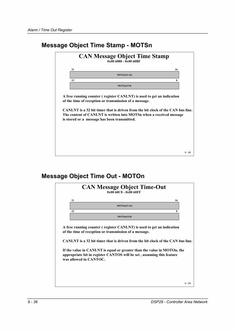
CAN Message Object Time Stamp 0x00 6080 - 0x00 60BF
15
1631
MOTSn[15:0]
MOTSn[31:16]
0
A free running counter ( register CANLNT) is used to get an indication of the time of reception or transmission of a message.
CANLNT is a 32 bit timer that is driven from the bit clock of the CAN bus line.The content of CANLNT is written into MOTSn when a received message is stored or a message has been transmitted.
Message Object Time Out - MOTOn
9 - 59
CAN Message Object Time-Out 0x00 60C0 - 0x00 60FF
15
1631
MOTOn[15:0]
MOTOn[31:16]
0
A free running counter ( register CANLNT) is used to get an indication of the time of reception or transmission of a message.
CANLNT is a 32 bit timer that is driven from the bit clock of the CAN bus line.
If the value in CANLNT is equal or greater than the value in MOTOn, the appropriate bit in register CANTOS will be set , assuming this feature was allowed in CANTOC.

Mailbox Memory
DSP28 - Controller Area Network 9 - 37
Mailbox Memory Message Identifier - CANMID
9 - 60
CAN Mailbox Memory0x00 6100 - 0x00 61FF
AME
1516293031
IDn[15:0]IDn[28:16]IDE
0
AAM
28Message Identifier Register (MID) Mailbox n
Identifier Extension Bit0 = Standard Identifier (11 Bits)1 = Extended Identifier (29 Bits)
Acceptance Mask Enable Bit ( receiver only)0 = no Acceptance Mask used. All identifier bits must match to receive the message1 = the corresponding Acceptance Mask is used)
Auto Answer Mode Bit ( transmitter only)0 = mailbox does not reply to remote requests.1 = if a matching Remote Request is received, the contents of this mailbox will be sent.
Message IdentifierStandard Frames : IDn[28:18] are usedExtended Frames : IDn[28:0] are used
MID0[15:0] = address 0x00 6100MID0[31:16] = address 0x00 6101
Message Control Field - CANMCF
9 - 61
CAN Mailbox Memory 0x00 6100 - 0x00 61FF
RTR
1516 41331
reserved reserved
0
DLC
3Message Control Field Register (MCF) Mailbox n
Transmit Priority LevelPriority compared to the other 31 mailboxes.Highest number has highest priority.
Data Length CodeValid numbers are 0 to 8.
Remote Transmission Request0 = no RTR requested.1 = for receiver mailboxes:
if TRS bit is set, a remote frame is transmitted and the corresponding data frame will be received in the same mailbox.
1 = for transmit mailboxes:if TRS bit is set, a remote frame is transmitted but the correspondingdata frame has to be received in another mailbox.
MCF0[15:0] = address 0x00 6102MCF0[31:16] = address 0x00 6103
TPL reserved
12 8 7 5
Mailbox Memory
9 - 38 DSP28 - Controller Area Network
Message Data Field Low - CANMDL
9 - 62
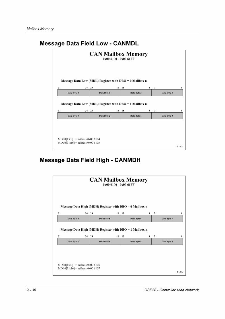
CAN Mailbox Memory 0x00 6100 - 0x00 61FF
2324 1531
Data Byte 0
0
Message Data Low (MDL) Register with DBO = 0 Mailbox n
MDL0[15:0] = address 0x00 6104MDL0[31:16] = address 0x00 6105
16 8 7
Data Byte 1 Data Byte 3Data Byte 2
2324 1531
Data Byte 3
0
Message Data Low (MDL) Register with DBO = 1 Mailbox n
16 8 7
Data Byte 2 Data Byte 0Data Byte 1
Message Data Field High - CANMDH
9 - 63
CAN Mailbox Memory 0x00 6100 - 0x00 61FF
2324 1531
Data Byte 4
0
Message Data High (MDH) Register with DBO = 0 Mailbox n
MDL0[15:0] = address 0x00 6106MDL0[31:16] = address 0x00 6107
16 8 7
Data Byte 5 Data Byte 7Data Byte 6
2324 1531
Data Byte 7
0
Message Data High (MDH) Register with DBO = 1 Mailbox n
16 8 7
Data Byte 6 Data Byte 4Data Byte 5

Lab Exercise 9
DSP28 - Controller Area Network 9 - 39
Lab Exercise 9
9 - 64
CAN Example : transmit a frameLab 9: Transmit a CAN message
CAN baud rate : 100 KBPS ( CAN low speed ) Transmit a one byte message every secondMessage Identifier 0x 1000 0000 ( extended frame)Use Mailbox #5 as transmit mailboxMessage content: status of the input switches ( GPIO B15-B8)CAN transceiver SN 65 HVD 230 ( Zwickau Adapter Board) :
Set jumper JP5 and JP6 to 1-2Set jumper JP4 to 2-3 ( enables on board line terminator of 120 Ohm)
DB9 (male) to connect the Adapter Board to CANPin 2 : CAN_L ; Pin 7 : CAN_H ; Pin 3 : GND
Preface
After this extensive description of all CAN registers of the C28x, it is time to carry out an exercise. Again, it is a good idea to start with some simple experiments to get our hard-ware to work. Later, we can try to refine the projects by setting up enhanced operation modes such as “Remote Transmission Request”, “Auto Answer Mode”, “Pipelined Mail-boxes” or “Wakeup Mode”. We will also refrain from using the powerful error recogni-tion and error management, which of course would be an essential part of a real project. To keep it simple, we will also use a polling method instead of an interrupt driven com-munication between the core of the DSP and the CAN mailbox server. Once you have a working example, it is much simpler to improve the code in this project by adding more enhanced operating modes to it. The CAN requires a transceiver circuit between the digital signals of the C28x and the bus lines to adjust the physical voltages. The Zwickau Adapter Board is equipped with two different types of CAN transceivers, a Texas Instruments SN65HVD230 for high speed ISO 11898 applications and a Phillips TJA1054, quite often used in the CAN for body electronics of a car. With the help of two jumpers (JP5, JP6), we can select the transceiver in use. For Lab 9 we will use the SN65HVD230. The physical CAN lines for ISO 11898 require a correct line termination at the ends of the transmission lines by 120 Ohm terminator resistors. If the C28x is placed at one of the end positions in your CAN network, you can use the on board 120 Ohm terminator by setting jumper JP4 to position 2-3. If the physical structure of the CAN in your laboratory does

Lab Exercise 9
9 - 40 DSP28 - Controller Area Network
not require the C28x to terminate the net, set JP4 to 1-2. Ask your teacher which set up is the correct one. To test your code, you will need a partner team with a second C28x doing Lab 10. This lab is an experiment to receive a CAN message and display its data at GPIO B7-B0 (8 LED’s on the Zwickau Adapter Board). If your laboratory does not provide any CAN in-frastructure, it is quite simple to connect the two boards. Use two female DB9 connectors, a twisted pair cable to connect pins 2-2 (CAN_L), 7-7 (CAN_H) and eventually 3-3 (GND) and plug them into the DB9 connectors of the Zwickau Adapter Board. Before you start the hard wiring, ask your teacher or a laboratory technician what exactly you are supposed to do to connect the boards!
Objective • The objective of Lab 9 is to transmit a one byte data frame every second via CAN.
• The actual data byte should be taken from input lines GPIO-B15 to B8. In case of the
Zwickau Adapter Board, these 8 lines are connected to 8 digital input switches.
• The baud rate for the CAN should be set to 100 kbps.
• The exercise should use extended identifier 0x1000 0000 for the transmit message. You can also use any other number as identifier, but please make sure that your part-ner team (Lab 10) knows about your change. If your classroom uses several eZdsp’s at the same time, it could be an option to set-up pairs of teams sharing the CAN by using different identifiers. It is also possible that due to the structure of the labora-tory set-up at your university, not all identifier combinations might be available to you. You surely don’t want to start the ignition of a motor control unit that is also connected to the CAN for some other experiments. Before you use any other ID’s ask your teacher!
• Use Mailbox #5 as your transmit mailbox
• Once you have started a CAN transmission wait for completion by polling the status
bit. Doing so we can refrain from using CAN interrupts for this first CAN exercise.
• Use CPU core timer 0 to generate the one second interval
Procedure
Open Files, Create Project File 1. Create a new project, called Lab9.pjt in E:\C281x\Labs.
Lab Exercise 9
DSP28 - Controller Area Network 9 - 41
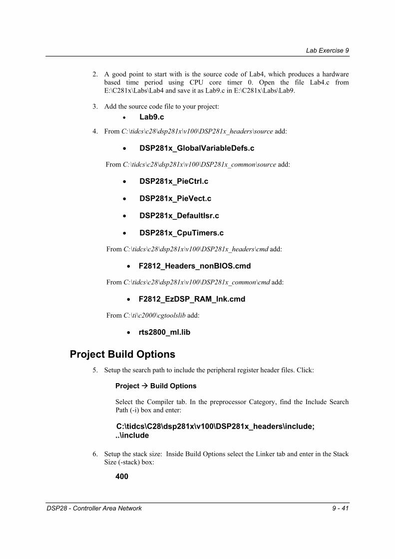
2. A good point to start with is the source code of Lab4, which produces a hardware based time period using CPU core timer 0. Open the file Lab4.c from E:\C281x\Labs\Lab4 and save it as Lab9.c in E:\C281x\Labs\Lab9.
3. Add the source code file to your project: • Lab9.c
4. From C:\tidcs\c28\dsp281x\v100\DSP281x_headers\source add:
• DSP281x_GlobalVariableDefs.c
From C:\tidcs\c28\dsp281x\v100\DSP281x_common\source add:
• DSP281x_PieCtrl.c
• DSP281x_PieVect.c
• DSP281x_DefaultIsr.c
• DSP281x_CpuTimers.c
From C:\tidcs\c28\dsp281x\v100\DSP281x_headers\cmd add:
• F2812_Headers_nonBIOS.cmd
From C:\tidcs\c28\dsp281x\v100\DSP281x_common\cmd add:
• F2812_EzDSP_RAM_lnk.cmd
From C:\ti\c2000\cgtoolslib add:
• rts2800_ml.lib
Project Build Options 5. Setup the search path to include the peripheral register header files. Click:
Project Build Options
Select the Compiler tab. In the preprocessor Category, find the Include Search Path (-i) box and enter:
C:\tidcs\C28\dsp281x\v100\DSP281x_headers\include; ..\include
6. Setup the stack size: Inside Build Options select the Linker tab and enter in the Stack
Size (-stack) box:
400

Lab Exercise 9
9 - 42 DSP28 - Controller Area Network
Close the Build Options Menu by Clicking <OK>.
Modify Source Code 7. Before we can start editing our own code we have to modify a portion of the Texas
Instruments Header file “DSP281x_ECan.h”, Version 1.0. This file has a bug inside the structures “CANMDL_BYTES” and “CANMDH_BYTES”. The order of bytes is not correct.
Search and edit struct CANMDL_BYTES and CANMDH_BYTES:
struct CANMDL_BYTES { // bits description
Uint16 BYTE3:8; // 31:24
Uint16 BYTE2:8; // 23:16
Uint16 BYTE1:8; // 15:8
Uint16 BYTE0:8; // 7:0
};
struct CANMDH_BYTES { // bits description
Uint16 BYTE7:8; // 63:56
Uint16 BYTE6:8; // 55:48
Uint16 BYTE5:8; // 47:40
Uint16 BYTE4:8; // 39:32
};
8. Open Lab9.c to edit. First, we have to adjust the while(1) loop of main to perform the next CAN transmission every 1 second. Recall that we initialized the CPU core timer 0 to interrupt every 50ms and to increment variable “CpuTimer0.InterruptCount” with every interrupt service. To generate a pause period of 1 second, we just have to wait until “CpuTimer0.InterruptCount” has reached 20. BUT, while we wait, we have to deal with the watchdog! One second without any watchdog service will be far too long; the watchdog will trigger a reset! Modify the code accordingly!
Lab Exercise 9
DSP28 - Controller Area Network 9 - 43
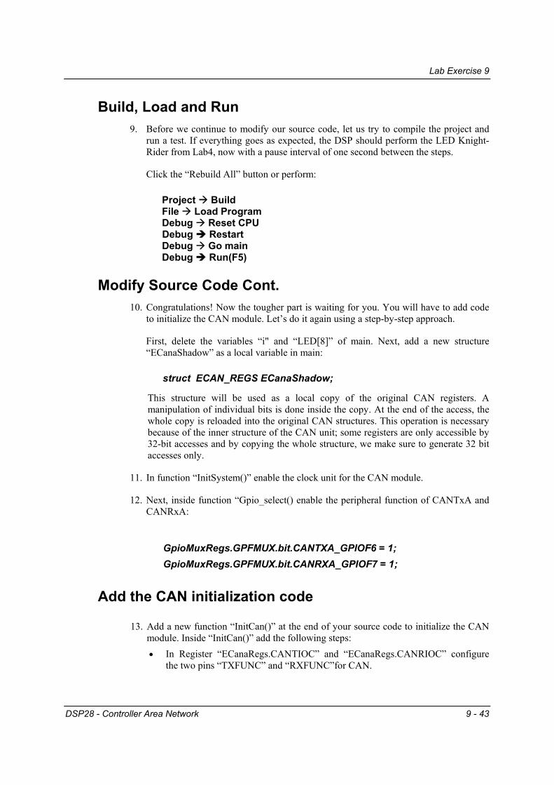
Build, Load and Run 9. Before we continue to modify our source code, let us try to compile the project and
run a test. If everything goes as expected, the DSP should perform the LED Knight-Rider from Lab4, now with a pause interval of one second between the steps.
Click the “Rebuild All” button or perform:
Project Build File Load Program Debug Reset CPU
Debug Restart Debug Go main Debug Run(F5)
Modify Source Code Cont. 10. Congratulations! Now the tougher part is waiting for you. You will have to add code
to initialize the CAN module. Let’s do it again using a step-by-step approach.
First, delete the variables “i" and “LED[8]” of main. Next, add a new structure “ECanaShadow” as a local variable in main:
struct ECAN_REGS ECanaShadow;
This structure will be used as a local copy of the original CAN registers. A manipulation of individual bits is done inside the copy. At the end of the access, the whole copy is reloaded into the original CAN structures. This operation is necessary because of the inner structure of the CAN unit; some registers are only accessible by 32-bit accesses and by copying the whole structure, we make sure to generate 32 bit accesses only.
11. In function “InitSystem()” enable the clock unit for the CAN module.
12. Next, inside function “Gpio_select() enable the peripheral function of CANTxA and CANRxA:
GpioMuxRegs.GPFMUX.bit.CANTXA_GPIOF6 = 1; GpioMuxRegs.GPFMUX.bit.CANRXA_GPIOF7 = 1;
Add the CAN initialization code
13. Add a new function “InitCan()” at the end of your source code to initialize the CAN module. Inside “InitCan()” add the following steps: • In Register “ECanaRegs.CANTIOC” and “ECanaRegs.CANRIOC” configure
the two pins “TXFUNC” and “RXFUNC”for CAN.

Lab Exercise 9
9 - 44 DSP28 - Controller Area Network
• Enable the HECC mode of the CAN module (Register “ECanaRegs.CANMC”). • To set-up the baud rate for the CAN transmission, we need to get access to the
bit timing registers. This access is requested by setting bit “CCR” of register “ECanaRegs.CANMC to 1.
• Before we can continue with the initialisation, we have to wait until the CAN module has granted this request. In this case the flag “CCE” of register “ECanaRegs.CANES” will be set to 1 by the CAN module. Install a wait construct into your code.
• Now we are allowed to set-up the bit timing parameters “BRP”, “TSEG1” and “TSEG2” of register “ECanaRegs.CANBTC”. Use the 100 kbps set-up from the following table:
9 9 -- 4444
CAN BitCAN Bit--Timing ExamplesTiming ExamplesBit Configuration for SYSCLK = 150 MHzBit Configuration for SYSCLK = 150 MHzSample Point at 80% of Bit Time :Sample Point at 80% of Bit Time :
Example 50 KBPS: Example 50 KBPS: TQ = (199+1)/150 MHz = 1.334 nsTQ = (199+1)/150 MHz = 1.334 ns
tseg1 = 1.334 ns ( 10 + 1) = 14.674 ns tseg1 = 1.334 ns ( 10 + 1) = 14.674 ns ttCANCAN = 20.010 ns = 20.010 ns tseg2 = 1.334 ns ( 2 + 1) = 4.002 nstseg2 = 1.334 ns ( 2 + 1) = 4.002 ns
22101019919950 KBPS50 KBPS
2210109999100 KBPS100 KBPS
2210107979125 KBPS125 KBPS
2210103939250 KBPS250 KBPS
2210101919500 KBPS500 KBPS
221010991 MBPS1 MBPS
TSEG2TSEG2TSEG1TSEG1BRPBRPCANCAN--BaudrateBaudrate
• After the access to register “ECanaRegs.CANBTC”, we have to re-enable the CAN modules access to this register. This is done by clearing bit “Change Configuration Request (CCR)” of register “ECanaRegs.CANMC”. Again we have to apply a wait loop until this command is acknowledged by the CAN module (Flag “CCE” of register “ECanaRegs.CANES” will be cleared by the CAN module as acknowledgement).
• Finally, we have to disable all mailboxes to exclude them from data communication and to allow write accesses into the message identifier registers of the mailbox of our choice. To disable all mailboxes we have to write a ‘0’ into all bit fields of register “ECanaRegs.CANME”.

Lab Exercise 9
DSP28 - Controller Area Network 9 - 45
14. In main, just before the CpuCoreTimer0 is started, add the function call of “InitCan()”.
15. At the beginning of your code, add a function prototype for “InitCan()”
Prepare Transmit Mailbox #5
16. In main, after the function call to “InitCan()”, add code to prepare the transmit mailbox. In this exercise, we will use mailbox #5, an extended identifier of 0x10000000 and a data length code of 1. Add the following steps: • Write the identifier into register “EcanaMboxes.MBOX5.MSGID”. • To transmit with extended identifiers set bit “IDE” of register
“EcanaMboxes.MBOX5.MSGID” to 1. • Configure Mailbox #5 as a transmit mailbox. This is done by setting bit MD5 of
register “ECanaRegs.CANMD” to 0. Caution! Due to the internal structure of the CAN-unit, we can’t execute single bit accesses to the original CAN registers. A good principle is to copy the whole register into a shadow register, manipulate the shadow and copy the modified 32 bit shadow back into its origin: ECanaShadow.CANMD.all = ECanaRegs.CANMD.all; ECanaShadow.CANMD.bit.MD5 = 0; ECanaRegs.CANMD.all = ECanaShadow.CANMD.all;
• Enable Mailbox #5:
ECanaShadow.CANME.all = ECanaRegs.CANME.all; ECanaShadow.CANME.bit.ME5 = 1; ECanaRegs.CANME.all = ECanaShadow.CANME.all;
• Set-up the Data Length Code Field (DLC) in Message Control Register “ECanaMboxes.MBOX5.MSGCTRL” to 1.
Add the Data Byte and Transmit 17. Now we are almost done. The only thing that’s missing is the periodical loading of
the data byte into the mailbox and the transmit request command. This must be done inside the while(1)-loop of main. Locate the code where we wait until variable “CpuTimer0.InterruptCount” has reached 20. Here add:
• Load the current status of the 8 input switches at GPIO-Port B (Bits 15 to 8) into register “ECanaMboxes.MBOX5.MDL.byte.BYTE0”
• Request a transmission of mailbox #5. Init register “ECanaShadow.CANTRS”. Set bit TRS5=1 and all other 31 bits to 0. Next, load the whole register into “ECanaRegs.CANTRS”

Lab Exercise 9
9 - 46 DSP28 - Controller Area Network
• Wait until the CAN unit has acknowledged the transmit request. The flag “ECanaRegs.CANTA.bit.TA5” will be set to 1 if your request has been acknowledged.
• Clear bit “ECanaRegs.CANTA.bit.TA5”. Again the access must be made as a 32 bit access:
ECanaShadow.CANTA.all = 0;
ECanaShadow.CANTA.bit.TA5 = 1;
ECanaRegs.CANTA.all = ECanaShadow.CANTA.all;
Build, Load and Run 18. Click the “Rebuild All” button or perform:
Project Build File Load Program Debug Reset CPU
Debug Restart Debug Go main Debug Run(F5)
19. Providing you have found a partner team with another C28x connected to your laboratory CAN system and waiting for a one-byte data frame with identifier 0x10000000 you can do a real network test. Modify the status of your input switches. The current status should be transmitted every second via CAN.
If your teacher can provide a CAN analyser you should be able to trace your data frames at the CAN. Your partner team should be able to receive your frames and use the information to update their LED’s.
If you end up in a fight between the two teams about whose code might be wrong, ask your teacher to provide a working receiver node. Recommendation for teachers: Store a working receiver code version in the internal Flash of one node and start this node out of flash memory.
END of LAB 9

Lab Exercise 10
DSP28 - Controller Area Network 9 - 47
Lab Exercise 10
9 9 -- 6565
CAN Example : receive a frameCAN Example : receive a frameLab 10: Receive a CAN message
CAN baud rate : 100 KBPS ( can low speed ) Receive a one byte message and show it on GPIO-Port B7…B0 ( 8 LED’s)Message Identifier 0x 1000 0000 ( extended frame)Use Mailbox #1 as receive mailboxCAN Transceiver SN 65 HVD 230 ( Zwickau Adapter Board) :
Set jumper JP5 and JP6 to 1-2Set jumper JP4 to 2-3 ( enables on board line terminator of 120 Ohm)
DB9 (male) to connect the Adapter Board to CANPin 2 : CAN_L ; Pin 7 : CAN_H ; Pin 3 : GND
Preface
This laboratory experiment is the second part of a CAN-Lab. Again we have to set up the physical CAN-layer according to the layout of your laboratory. The CAN requires a transceiver circuit between the digital signals of the C28x and the bus lines to adjust the physical voltages. The Zwickau Adapter Board is equipped with two different types of CAN transceivers, a Texas Instruments SN65HVD230 for high speed ISO 11898 applications and a Phillips TJA1054, quite often used in the CAN for body electronics of a car. With the help of two jumpers (JP5, JP6), you can select the trans-ceiver in use. For Lab 10 we will use the SN65HVD230. The physical CAN lines for ISO 11898 require a correct line termination at the ends of the transmission lines by 120 Ohm terminator resistors. If the C28x is placed at one of the end positions in your CAN network, you can use the on-board terminator of 120 Ohms by set-ting jumper JP4 to position 2-3. If the physical structure of the CAN in your laboratory does not require the C28x to terminate the net, set JP4 to 1-2. Ask your teacher which set-up is the correct one. To test your code you will need a partner team with a second C28x doing Lab 9, e.g. send-ing a one byte message with identifier 0x10 000 000 every second. Before you start the hard wiring, ask your teacher or a laboratory technician what exactly you are supposed to do to connect the boards!
Lab Exercise 10
9 - 48 DSP28 - Controller Area Network
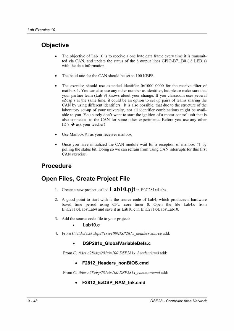
Objective • The objective of Lab 10 is to receive a one byte data frame every time it is transmit-
ted via CAN, and update the status of the 8 output lines GPIO-B7...B0 ( 8 LED’s) with the data information..
• The baud rate for the CAN should be set to 100 KBPS.
• The exercise should use extended identifier 0x1000 0000 for the receive filter of
mailbox 1. You can also use any other number as identifier, but please make sure that your partner team (Lab 9) knows about your change. If you classroom uses several eZdsp’s at the same time, it could be an option to set up pairs of teams sharing the CAN by using different identifiers. It is also possible, that due to the structure of the laboratory set-up of your university, not all identifier combinations might be avail-able to you. You surely don’t want to start the ignition of a motor control unit that is also connected to the CAN for some other experiments. Before you use any other ID’s ask your teacher!
• Use Mailbox #1 as your receiver mailbox
• Once you have initialized the CAN module wait for a reception of mailbox #1 by
polling the status bit. Doing so we can refrain from using CAN interrupts for this first CAN exercise.
Procedure
Open Files, Create Project File 1. Create a new project, called Lab10.pjt in E:\C281x\Labs.
2. A good point to start with is the source code of Lab4, which produces a hardware based time period using CPU core timer 0. Open the file Lab4.c from E:\C281x\Labs\Lab4 and save it as Lab10.c in E:\C281x\Labs\Lab10.
3. Add the source code file to your project: • Lab10.c
4. From C:\tidcs\c28\dsp281x\v100\DSP281x_headers\source add:
• DSP281x_GlobalVariableDefs.c
From C:\tidcs\c28\dsp281x\v100\DSP281x_headers\cmd add:
• F2812_Headers_nonBIOS.cmd
From C:\tidcs\c28\dsp281x\v100\DSP281x_common\cmd add:
• F2812_EzDSP_RAM_lnk.cmd
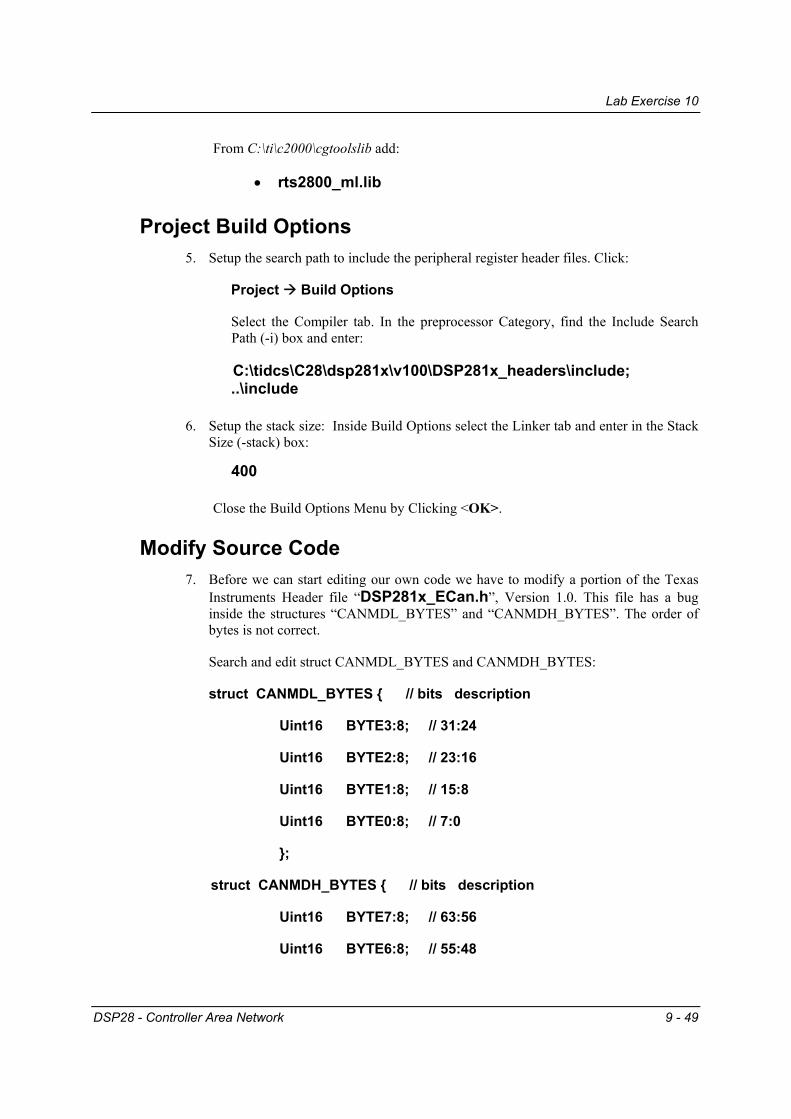
Lab Exercise 10
DSP28 - Controller Area Network 9 - 49
From C:\ti\c2000\cgtoolslib add:
• rts2800_ml.lib
Project Build Options 5. Setup the search path to include the peripheral register header files. Click:
Project Build Options
Select the Compiler tab. In the preprocessor Category, find the Include Search Path (-i) box and enter:
C:\tidcs\C28\dsp281x\v100\DSP281x_headers\include; ..\include
6. Setup the stack size: Inside Build Options select the Linker tab and enter in the Stack
Size (-stack) box:
400
Close the Build Options Menu by Clicking <OK>.
Modify Source Code 7. Before we can start editing our own code we have to modify a portion of the Texas
Instruments Header file “DSP281x_ECan.h”, Version 1.0. This file has a bug inside the structures “CANMDL_BYTES” and “CANMDH_BYTES”. The order of bytes is not correct.
Search and edit struct CANMDL_BYTES and CANMDH_BYTES:
struct CANMDL_BYTES { // bits description
Uint16 BYTE3:8; // 31:24
Uint16 BYTE2:8; // 23:16
Uint16 BYTE1:8; // 15:8
Uint16 BYTE0:8; // 7:0
};
struct CANMDH_BYTES { // bits description
Uint16 BYTE7:8; // 63:56
Uint16 BYTE6:8; // 55:48

Lab Exercise 10
9 - 50 DSP28 - Controller Area Network
Uint16 BYTE5:8; // 47:40
Uint16 BYTE4:8; // 39:32
};
8. Open Lab10.c to edit.
Remove the function prototype and the definition of function “cpu_timer0_isr().” We do not use the CPU core timer in this lab exercise.
In “main()”, remove the local variables “i” and “LED[8]”.
Between the start of “main” and the “while(1)-loop of “main()”, remove all function calls apart from “InitSystem()” and “Gpio_select()”.
Inside the while(1)-loop remove all old lines, just keep the service instructions for the watchdog:
EALLOW;
SysCtrlRegs.WDKEY = 0x55; SysCtrlRegs.WDKEY = 0x55; EDIS;
Build, Load and Run 9. Before we continue to modify our source code lets try to compile the project in this
stage to find any syntax errors.
Click the “Rebuild All” button or perform:
Project Build File Load Program Debug Reset CPU
Debug Restart Debug Go main Debug Run(F5)
If everything went like expected you should end up with 0 errors, 0 warnings and 0 remarks.
Modify Source Code Cont. 10. Congratulations! Now let’s install the CAN – receiver part.
First, add a new structure “ECanaShadow” as a local variable in main: struct ECAN_REGS ECanaShadow;

Lab Exercise 10
DSP28 - Controller Area Network 9 - 51
This structure will be used as a local copy of the original CAN registers. A manipulation of individual bits is done inside the copy. At the end of the access the whole copy is reloaded into the original CAN structures. This principle of operation is necessary because of the inner structure of the CAN unit; some registers are only accessible by 32-bit accesses and by copying the whole structure, we make sure to generate 32-bit accesses only.
11. In function “InitSystem()” enable the clock unit for the CAN module.
12. Next, inside function “Gpio_select()”, enable the peripheral function of CANTxA and CANRxA:
GpioMuxRegs.GPFMUX.bit.CANTXA_GPIOF6 = 1; GpioMuxRegs.GPFMUX.bit.CANRXA_GPIOF7 = 1;
Add the CAN initialization code
13. Add a new function “InitCan()” at the end of your source code to initialize the CAN module. Inside “InitCan()”, add the following steps: • In Register “ECanaRegs.CANTIOC” and “ECanaRegs.CANRIOC” configure
the two pins “TXFUNC” and “RXFUNC”for CAN. • Enable the HECC mode of the CAN module (Register “ECanaRegs.CANMC”). • To set-up the baud rate for the CAN transmission we need to get access to the bit
timing registers. This access is requested by setting bit “CCR” of register “ECanaRegs.CANMC to 1.
• Before we can continue with the initialization we have to wait until the CAN module has granted this request. In this case, the flag “CCE” of register “ECanaRegs.CANES” will be set to 1 by the CAN module. Install a wait construct into your code.
• Now we are allowed to set-up the bit timing parameters “BRP”, “TSEG1” and “TSEG2” of register “ECanaRegs.CANBTC”. Use the 100 kbps set-up from the following table:

Lab Exercise 10
9 - 52 DSP28 - Controller Area Network
9 9 -- 4444
CAN BitCAN Bit--Timing ExamplesTiming ExamplesBit Configuration for SYSCLK = 150 MHzBit Configuration for SYSCLK = 150 MHzSample Point at 80% of Bit Time :Sample Point at 80% of Bit Time :
Example 50 KBPS: Example 50 KBPS: TQ = (199+1)/150 MHz = 1.334 nsTQ = (199+1)/150 MHz = 1.334 ns
tseg1 = 1.334 ns ( 10 + 1) = 14.674 ns tseg1 = 1.334 ns ( 10 + 1) = 14.674 ns ttCANCAN = 20.010 ns = 20.010 ns tseg2 = 1.334 ns ( 2 + 1) = 4.002 nstseg2 = 1.334 ns ( 2 + 1) = 4.002 ns
22101019919950 KBPS50 KBPS
2210109999100 KBPS100 KBPS
2210107979125 KBPS125 KBPS
2210103939250 KBPS250 KBPS
2210101919500 KBPS500 KBPS
221010991 MBPS1 MBPS
TSEG2TSEG2TSEG1TSEG1BRPBRPCANCAN--BaudrateBaudrate
• After the access to register “ECanaRegs.CANBTC” we have to re-enable the CAN modules access to this register. This is done by clearing bit “Change Configuration Request (CCR)” of register “ECanaRegs.CANMC”. Again, we have to apply a wait loop until this command is acknowledged by the CAN module (Flag “CCE” of register “ECanaRegs.CANES” will be cleared by the CAN module as acknowledgement).
• Finally, we have to disable all mailboxes to exclude them from data communication and to allow write accesses into the message identifier registers of the mailbox of our choice. To disable all mailboxes we have to write a ‘0’ into all bit fields of register “ECanaRegs.CANME”.
14. In main, just before we enter the while(1)-loop, add the function call to “InitCan()”. 15. At the beginning of your code, add a function prototype for “InitCan()”
Prepare Receiver Mailbox #1
16. In main, after the function call of “InitCan()” add code to prepare the receiver mailbox. In this exercise, we will use mailbox #1, an extended identifier of 0x10000000 and a data length code of 1. Add the following steps: • Write the identifier into register “EcanaMboxes.MBOX1.MSGID”. • To transmit with extended identifiers set bit “IDE” of register
“EcanaMboxes.MBOX1.MSGID” to 1. • Configure Mailbox #1 as a receive mailbox. This is done by setting bit MD1 of
register “ECanaRegs.CANMD” to 1. Caution! Due to the internal structure of the CAN-unit, we can’t execute single bit accesses to the original CAN registers. A
Lab Exercise 10
DSP28 - Controller Area Network 9 - 53
good principle is to copy the whole register into a shadow register, manipulate the shadow and copy the modified 32 bit shadow back into its origin: ECanaShadow.CANMD.all = ECanaRegs.CANMD.all; ECanaShadow.CANMD.bit.MD1 = 1; ECanaRegs.CANMD.all = ECanaShadow.CANMD.all;
• Enable Mailbox #1:
ECanaShadow.CANME.all = ECanaRegs.CANME.all; ECanaShadow.CANME.bit.ME1 = 1; ECanaRegs.CANME.all = ECanaShadow.CANME.all;
Add a polling loop for a message in mailbox 1 17. Now we are almost done. The only thing that’s missing is the final modification of
the while(1)-loop of main. All we have to add is a polling loop to wait for a received message in mailbox #1. The register “ECanaRegs.CANRMP” – Bit field “RMP1” will be set to 1 if a valid message has been received. All we have to do is to wait for this event to happen in a sort of “do-while” loop.
NOTE1: It is highly recommended to copy ECanaRegs.CANRMP into the local variable “ECanaShadow.CANRMP” before any logical test of bit RMP1 is made.
NOTE2: Do not forget to include the watchdog-service code lines into your wait construct!
18. If Bit RMP1 was set to 1 by the CAN – Mailbox we can take the data byte 0 out of the mailbox and load it onto the GPIO-B7…B0 ( 8 LED’)s:
GpioDataRegs.GPBDAT.all = ECanaMboxes.MBOX1.MDL.byte.BYTE0;
19. Finally, we have to reset bit RMP1. This is done by writing a ‘1’ into it:
ECanaShadow.CANRMP.bit.RMP1 = 1;
ECanaRegs.CANRMP.all = ECanaShadow.CANRMP.all;
Build, Load and Run again 20. Click the “Rebuild All” button or perform:
Project Build File Load Program Debug Reset CPU
Debug Restart Debug Go main Debug Run(F5)

Lab Exercise 10
9 - 54 DSP28 - Controller Area Network
21. Providing you have found a partner team with another C28x connected to your laboratory CAN system and transmitting a one-byte data frame with identifier 0x10000000 you can do a real network test. Ask your partner team to modify their input switches and transmit it every second via CAN.
If your teacher can provide a CAN analyzer you can also generate a transmit message out of this CAN analyzer.
If you end up in a fight between the two teams about whose code might be wrong, ask your teacher to provide a working transmitter node.
Recommendation for teachers: Store a working transmitter code version in the internal Flash of one node and start this node out of flash memory.
END of LAB 10
What’s next?
DSP28 - Controller Area Network 9 - 55
What’s next? Congratulations! You’ve successfully finished your first two lab exercises using Controller Area Network. As mentioned earlier in this chapter these two labs were chosen as a sort of “getting started” with CAN. To learn more about CAN it is necessary to book additional classes at your university.
To experiment a little bit more with CAN, choose one of the following optional exercises:
Lab 10A : Combine Lab9 (CAN – Transmit) and Lab10 (CAN-Receive) into a bi-directional solution. The task for your node is to transmit the status of the input switches (B15…B8) to CAN every second (or optional: every time the status has changed) with a one-byte frame and identifier 0x10 000 000. Simultaneously, your node is requested to receive CAN messages with identifier 0x11 000 000. Byte 1 of the received frame should be displayed at the GPIO-Port pins B7…B0, which in case of the Zwickau Adapter board are connected to 8 LED’s.
Lab 10B: Try to improve Lab9 and Lab10A by using the C28x Interrupt System for the receiver part of the exercises. Instead of polling the “CANRMP-Bit field” to wait for an incoming message your task is to use a mailbox interrupt request to read out the mailbox when necessary.
Lab 10C: We did not consider any possible error situations on the CAN side so far. That’s not a good solution for a practical project. Try to improve your previous CAN experiments by including the service of potential CAN error situations. Recall, the CAN error status register flags all possible error situations. A good solution would be to allow CAN error interrupts to request their individual service routines in case of a CAN failure. What should be done in the case of an error request? Answer: Try to use the PWM – loudspeaker at output line T1PWM to generate a sound. By using different frequencies, you can signal the type of failure.
Another option could be to monitor the status of the two CAN – error counters and show their current values with the help of the 8 LED’s at GPIO-B7…B0.
If your laboratory is equipped with a CAN failure generator like “CANstress” (Vector Informatik GmbH, Germany) you can generate reproducible disturbance of the physical layer, you can destroy certain messages and manipulate certain bit fields with bit resolution. Ask your laboratory technician whether you are allowed to use this type of equipment to invoke CAN errors.
Lab 10D: An enhanced experiment is to request a remote transmission from another CAN-node. An operating mode, that is quite often used is the so-called “automatic answer mode”. A transmit mailbox, that receives a remote transmission request (“RTR”) answers automatically by transmitting a predefined frame. Try to establish this operating mode for the transmitter node
What’s next?
9 - 56 DSP28 - Controller Area Network
(Lab9 or Lab10B). Wait for a RTR and send the current status of the input switches back to the requesting node. The node that has requested the remote transmission should be initialized to wait for the requested answer and display byte 1 of the received data frame at the 8 LED’s (GPIO B7…B0).
There are a lot more options for RTR operations available. Again, look out for additional CAN classes at your university!