tm9-2990-206-34&p - liberated manuals
TRANSCRIPT
This copy is a reprint which includes currentpages from Changes 1 and 2. TM 9-2990-206-34&P
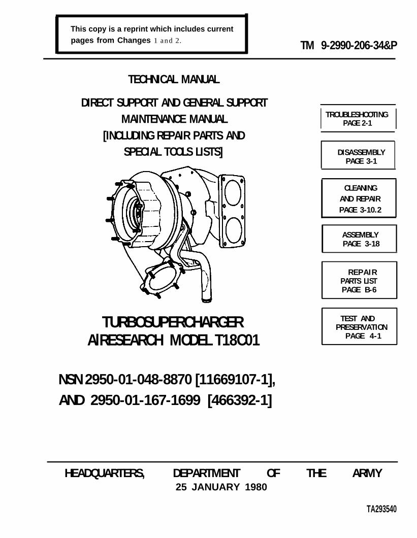
TECHNICAL MANUAL
DIRECT SUPPORT AND GENERAL SUPPORTMAINTENANCE MANUAL
[INCLUDING REPAIR PARTS ANDSPECIAL TOOLS LISTS]
TURBOSUPERCHARGERAlRESEARCH MODEL T18C01
NSN 2950-01-048-8870 [11669107-1],AND 2950-01-167-1699 [466392-1]
I TROUBLESHOOTINGPAGE 2-1 I
DISASSEMBLYPAGE 3-1
ASSEMBLYPAGE 3-18
REPAIRPARTS LISTPAGE B-6
TEST ANDPRESERVATION
PAGE 4-1
HEADQUARTERS, DEPARTMENT OF THE ARMY25 JANUARY 1980
TA293540
CLEANINGAND REPAIRPAGE 3-10.2
TM 9-2990-206-34&P
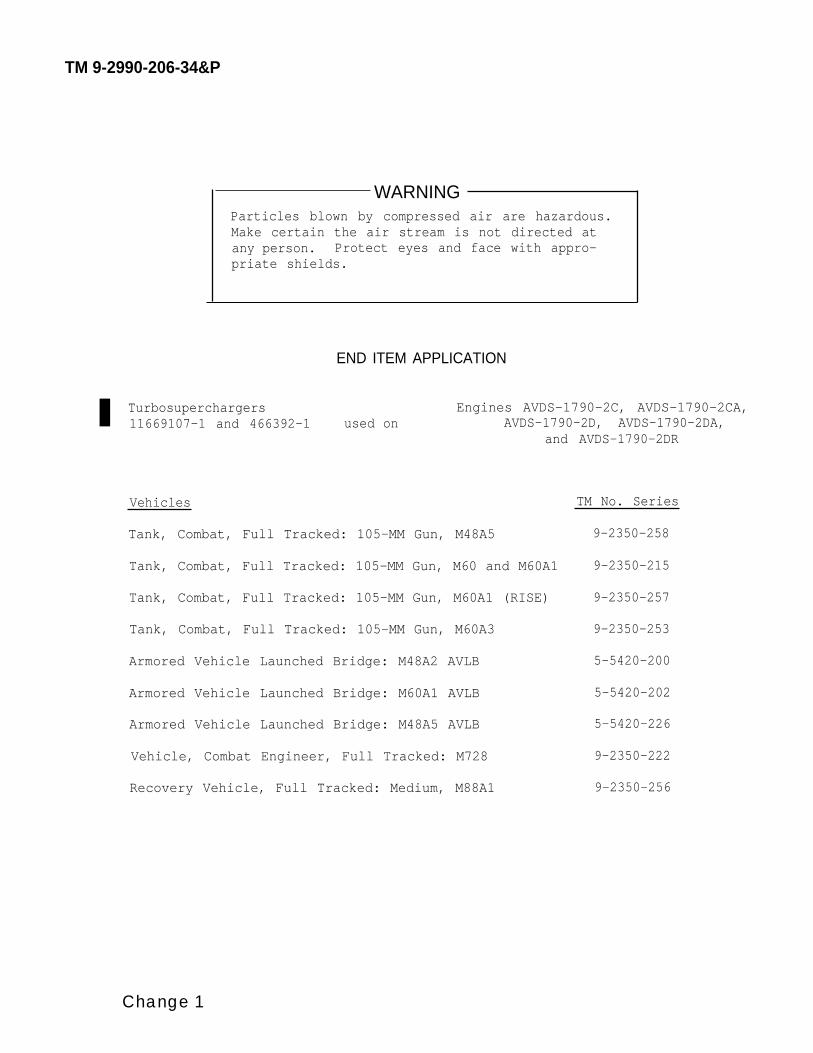
WARNINGParticles blown by compressed air are hazardous.Make certain the air stream is not directed atany person. Protect eyes and face with appro-priate shields.
END ITEM APPLICATION
Turbosuperchargers Engines AVDS-1790-2C, AVDS-1790-2CA,11669107-1 and 466392-1 used on AVDS-1790-2D, AVDS-1790-2DA,
and AVDS-1790-2DR
Vehicles
Tank, Combat, Full Tracked: 105-MM Gun, M48A5
Tank, Combat, Full Tracked: 105-MM Gun, M60 and M60A1
Tank, Combat, Full Tracked: 105-MM Gun, M60A1 (RISE)
Tank, Combat, Full Tracked: 105-MM Gun, M60A3
Armored Vehicle Launched Bridge: M48A2 AVLB
Armored Vehicle Launched Bridge: M60A1 AVLB
Armored Vehicle Launched Bridge: M48A5 AVLB
Vehicle, Combat Engineer, Full Tracked: M728
Recovery Vehicle, Full Tracked: Medium, M88A1
TM No. Series
9-2350-258
9-2350-215
9-2350-257
9-2350-253
5-5420-200
5-5420-202
5-5420-226
9-2350-222
9-2350-256
Change 1
TM 9-2990-206-34&P
ChangeNo. 2
C2HEADQUARTERS
DEPARTMENT OF THE ARMYWashington, DC, 8 Februury 1985
Direct Support and General Support Maintenance Manual( Inc lud ing Repa i r Pa r t s and Spec ia l Too l s L i s t )
f o r
TURBOSUPERCHARGER
AI RESEARCH MODEL T18C01NSN 2950-01-048-8870 ( 11669107-1)AND 2950-01-167-1699 (466392-1)
TM 9-2990-206-34&P, 25 January 1980, is changed as follows:1. Remove old pages and insert new pages as indicated below.2. New or changed material is indicated by a vert ical bar in the margin ofthe page.
Remove pages Inse r t pages
i and ii i and ii
F i l e th i s change shee t in f ron t o f the pub l i ca t ion fo r r e fe rence purposes .

TM 9-2990-206-34&P
By Order of the Secretary of the Army
Official:
JOHN A. WICKHAM, JR.General United States Army
Chief of stuff
DONALD J. DELANDROBrigadier General United States Army
The Adjutant General
Distribution
TO be distributed in accordance with DA Form 12-37, Direct and General Support Maintenancerequirements for Recovery Vehicle, Medium, M88A1; Tanks, Combat, Full Tracked, 105mm, M60;Miscellaneous Combat Vehicle, Combat Engineer, Full Track, M728; Tank Bridge Launcher, At’ LB; Tank,Combat, Full Tracked, 105mm, M60A1 (RISE); Tank Combat, Full Tracked, 105mm, M48A5 and Tank,Combat, W/Turret M60A3.

ChangeNo. 1
c lHEADQUARTERS
DEPARTMENT OF THE ARMYWashington, DC, 27 April 1984
Direct Support and General Support Maintenance Manual( Inc lud ing Repa i r Pa r t s and Spec ia l Too l s L i s t )
f o r
TURBOSUPERCHARGER
AIRESEARCH MODEL T18C01NSN 2950-01-048-8870 ( 11669107-1)AND 2950-01-167-1699 (466392-1 )
TM 9-2990-206-34&P, 25 January 1980, is changed as follows:
1. Title is changed as shown above.2. Remove and insert pages as indicated below.
Remove pages Insert pages
Warning pagei thru iv1-1 and 1-2None1-3 and 1-43-3 and 3-43-9 and 3-10None3-15 and 3-16None3-23 thru 3-26None3-27 (3-28 blank)B-1 and B-2B-7 and B-8NoneB-9 thru B-11 (B-12 blank)Index 1 through Index 3Cover
Warning pagei thru iv1-1 and 1-21-2.1 (l-2.2 blank)1-3 and 1-43-3 and 3-43-9 and 3-103-10.1 and 3-10.23-15 and 3-163-16.1 (3-16.2 blank)3-23 thru 3-26(3-26.1 blank) 3-26.23-27 thru 3-30B-1 and B-2B-7 and B-8B-8.1 thru B-8.4B-9 thru B-12Index 1 through Index 3Cover
3. New or changed text material is indicated by a vertical bar in the margin. Anillustration change is indicated by a miniature pointing hand.
4. Retain this sheet in front of manual for reference purposes.
TM 9-2990-206-34&P
By Order of the Secretary of the Army:
JOHN A. WICKHAM, JR.General, United States Army
Chief of Staff
Official:
ROBERT M. JOYCEMajor General, United States Army
The Adjutant General
Distribution:
To be distributed in accordance with DA Form 12-37, Direct and General Support Maintenancerequirements for Recovery~Vehicle, Medium, M88Al; Tanks,Combat, Full Tracked, l05MM, M60, M60A1;Combat Engineer, Full Track, M728; Tank, Bridge Launcher, AVLB; Tank, Combat, Full Tracked: 105MMGun, M60A1 (RISE); Tank, Combat, Full Tracked, 105MM Gun, M48A5, and M60A3 Tank Turret.
TM9-2990-206-34&P
*TM 9-2990-206-34&P
HEADQUARTERSDEPARTMENT OF THE ARMYWashington, DC, 25 January 1980
Direct and General Support Maintenance Manual(Including Repair Parts, And Special Tools List)
for
TURBOSUPERCHARGERAIRESEARCH MODEL T18C01
NSN 2950-01-048-8870 (11669107-1) and2950-01-167-1699 (466392-1)
Current as of 15 December 1983
REPORTING ERRORS AND RECOMMENDING IMPROVEMENTS
You can help improve this manual. If you find any mistakes or if you know of a way to improve theprocedures, please let us know. Mail your letter, DA Form 2028 (Recommended Changes toPublications and Blank Forms), or DA Form 2028-2 located in the back of this manual direct to:Commander, US Army Tank-Automotive Command, Warren, MI 48090, ATTN: DRSTA-MB. A replywill be furnished to you.
CHAPTER 1
Section ISection II
CHAPTER 2
Section ISection II
CHAPTER 3
Section ISection II
TABLE OF CONTENTS
Page
HOW TO USE THIS MANUAL . . . . . . . . . . . . . . . . . . . . . . . . . . . . . . . . . . . . . . . . . . . iii
INTRODUCTION . . . . . . . . . . . . . . . . . . . . . . . . . . . . . . . . . . . . . . . . . . . . . . . . . . . . 1-1
General Information . . . .. . . . . . . . . . . . . . . . . . . . . . . . . . . . . . . . . . . . . . . . . 1-1Equipment Description and Data . . . . . . . . . . . . . . . . . . . . . . . . . . . . . . . . . . 1-2
MAINTENANCE INSTRUCTIONS . . . . . . . . . . . . . . . . . . . . . . . . . . . . . . . . . . . . . . . . 2-1
Troubleshooting . . . . . . . . . . . . . . . . . . . . . . . . . . . . . . . . . . . . . . . . . . . . . . . . . 2-1General Maintenance . . . . . . . . . . . . . . . . . . . . . . . . . . . . . . . . . . . . . . . . . . . . . 2-5
MAINTENANCE OPERATIONS . . . . . . . . . . . . . . . . . . . . . . . . . . . . . . . . . . . . . . . . . . 3-1
General . . . . . . . . . . . . . . . . . . . . . . . . . . . . . . . . . . . . . . . . . . . . . . . . . . . . . . . . . 3-1Disassemble . . . . . . . . . . . . . . . . . . . . . . . . . . . . . . . . . . . . . . . . . . . . . . . . . . . . . 3-1
Section III Cleaning, inspection, and Repair . . . . . . . . . . . . . . . . . . . . . . . . . . . . . . 3-10.2Section IV Assembly . . . . . . . . . . . . . . . . . . . . . . . . . . . . . . . . . . . . . . . . . . . . . . . . . . . . . . . . 3-18
CHAPTER 4 TEST AND PRESERVATION . . . . . . . . . . . . . . . . . . . . . . . . . . . . . . . . . . . . . . . . . . . 4-1
*This manual supersedes TM 9-2990-200-34, 30 January 1973 Change 2 i
APPENDIX A. REFERENCES . . . . . . . . . . . . . . . . . . . . . . . . . . . . . . . . . . . . . . . . . . . . . . A-1
Section I General Information . . . . . . . . . . . . . . . . . . . . . . . . . . . . . . . . . . . . . . . A-1Section 11 Technical and Reference Manuals . . . . . . . . . . . . . . . . . . . . . . . . . . . . A-1
APPENDIX B. REPAIR PARTS AND SPECIAL TOOLS LISTS . . . . . . . . . . . . . . . . . . . . . . . . . . . B-1
Section I Introduction . . . . . . . . . . . . . . . . . . . . . . . . . . . . . . . . . . . . . . . . . . . . . . . . . B-1Section II Repair Parts List . . . . . . . . . . . . . . . . . . . . . . . . . . . . . . . . . . . . . . . . B-6Section III Special Tools List . . . . . . . . . . . . . . . . . . . . . . . . . . . . . . . . . . . . . . B-10Section IV National Stock Number and Part Number Index . . . . . . . . . . . . . . . . . . . . . . . . B-ll
APPENDIX C. EXPENDABLE SUPPLIES AND MATERIALS LIST . . . . . . . . . . . . . . . . . . . . . . . .. C-1
ALPHABETICAL INDEX . . . . . . . . . . . . . . . . . . . . . . . . . . . . . . . . . . . . . INDEX
TM 9-2990-206-34&P
i i
TM 9-2990-206-34&P
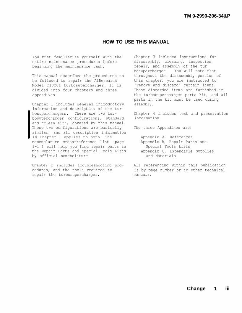
HOW TO USE THIS MANUAL
You must familiarize yourself with theentire maintenance procedures beforebeginning the maintenance task.
This manual describes the procedures tobe followed to repair the AiResearchModel T18C01 turbosupercharger. It isdivided into four chapters and threeappendixes.
Chapter 1 includes general introductoryinformation and description of the tur-bosuperchargers. There are two tur-bosupercharger configurations, standardand “clean air”, covered by this manual.These two configurations are basicallysimilar, and all descriptive informationin Chapter 1 applies to both. Thenomenclature cross-reference list (page1-1 ) will help you find repair parts inthe Repair Parts and Special Tools Listsby official nomenclature.
Chapter 2 includes troubleshooting pro-cedures, and the tools required torepair the turbosupercharger.
Chapter 3 includes instructions fordisassembly, cleaning, inspection,repair, and assembly of the tur-bosupercharger. You will note thatthroughout the disassembly portion ofthis chapter, you are instructed to“remove and discard” certain items.These discarded items are furnished inthe turbosupercharger parts kit, and allparts in the kit must be used duringassembly.
Chapter 4 includes test and preservationinformation.
The three Appendixes are:
Appendix A, ReferencesAppendix B, Repair Parts and
Special Tools ListsAppendix C, Expendable Supplies
and Materials
All referencing within this publicationis by page number or to other technicalmanuals.
Change 1 iii

TM 9-299-206-34&P
Turbosupercharger - typicalleft hand mounting.
iv

TM 9-2990-206-34&P
CHAPTER 1
INTRODUCTION
1-1. SCOPE.
Section 1. GENERAL INFORMATION
a. Type of Manual. This technicalmanual contains instructions for Directand General Support Maintenance of theAiResearch Industrial Division ModelT18C01 turbosupercharger.
b. Identification. The two con-figurations of Model T18C01 turbosuper-chargers covered by this manual are partnumbers 466392-1 (“clean air”) and11669107-1 (standard). These two con-figurations can be either right or lefthand mounted on various AVDS-1790 seriesengines used in army vehicles.
c. Purpose of Equipment. Turbo-superchargers are exhaust gas drivencentrifugal compressors.Their purposesis to increase the amount of air deli-vered to engine cylinders above thatavailable through unassisted air intake
1-2. MAINTENANCE FORMS, RECORDS,AND REPORTS.
Department of the Army forms and recordsused for equipment maintenance will bethose prescribed by TM 38-750, The ArmyMaintenance Management System (TAMMS).
1-3. NOMENCLATURE CROSS-REFERENCE LIST.
This listing includes nomenclature cross-references used in this manual.
Common Name Official Nomenclature
Backplate . . . . . . . . . . . . . . . . . . . . . . . . . . . . . . Back Plate, SuperchargerBolt . . . . . . . . . .. . . . . . . . . . . . . . . . . . . . . . . . . Bolt, MachineCenter Housing . . . . . . . . . . . . . . . . . . . . . . . ..Housing Assembly, CenterClamp . . . . . . ... . . . . . . . . . . . . . . . . . . . . . . . . . Coupling, Clamp, GroovedCompressor Wheel . . . . . . . . . . . . . . . . . . . . . . . Impeller, TurbosuperchargerCompressor Wheel Nut . . . . . . . . . . . . . . . . . ..Nut, ImpellerHeat Shield . . . . ... . . . . . . . . . . . . . . . . . . . . . Shield, TurbosuperchargerInsert . . . . . . . . . . . . . . . . . . . . . . . . . . . .... . . Insert, Screw ThreadLockwasher . . . . . . .. . . . . . . . . . . . . . . . . . . . . . Washer, LockNut . . . . . . . . . . .. . . . . . . . . . . . . . . . . . . . . . . . . Nut, Self-locking, Castellated, HexagonNut . . . . . . . . . . . . . . . . . . . . . . . . . . . . . . . .. . . . Nut, Self-locking, HexagonOil Drain Tube . . . . . . . . . . . . . . . . . . . . . . . . . Tube Assembly, Metal"O" Ring . . . . . . . . . . . . . . . . . . . . . . . . , . . . . . . Packing, Preformed"O" Ring . . . . . . . . . . . . . . . . . . . . .. . .. . . . ... Seal, RingSeal Ring . . . . . . . . . . . . . . . . . . . . . . . . . . . . . . Seal, Ring, MetalShroud . . . . . . . . . . . . . . .. . . . . . . . . . . . . . . ... Wheel, ShroudSpacer Ring . . . . . . . . . . . . . . . . . . . . . . . . . . . . Ring, TurbochargerStud . . .. . . . . . . . . . . . . . . . . . . . . . . . . . . . . . . . Stud, PlainThrust Ring . . . . . . . . . . . . . . . . . . . . . . . . . . . . Ring, Thrust, TurbochargerThrust Washer . . . . . . . . . . . . . . . . . . . . . . . . . . Washer, Bearing, ThrustTurbine Wheel . . . . . . . . . . . . . . . . . . . . . . . . . . Turbine Wheel Assembly
Change 1 1-1

1-4. REPORTING EQUIPMENT IMPROVE- cedure, just simply tell why the designMENT RECOMMENDATIONS (EIR). is unfavorable or why a procedure is
difficult. EIR’s may be submitted onEIR’S can and must be submitted by anyone SF 368 (Quality Deficiency Report).who is aware of an unsatisfactory condi- Mail directly to Commander, U. S. Armytion with the equipment design or use. Tank-Automotive Materiel ReadinessIt is not necessary to show a new design Command, Warren, MI 48090, ATTN: DRSTA-MPor list a better way to perform a pro- A reply will be furnished to you.
Section il. EQUIPMENT DESCRIPTION AND DATA
1-5. DESCRIPTION.
a. General. Engines equipped withturbosuperchargers deliver more powerper pound of fuel than unturbosuper-charged engines. Turbosuperchargersmake use of the heat energy lostthrough engine exhaust gases. Exhaustgases from the engine drive the turbinewheel assembly which in turn drives theturbocharger impeller (compressor wheel).
b. Operation. The exhaust gasesfrom the engine enter the turbinehousing through the exhaust connectionon the turbine housing. The gases flowaround the housing and radially inward.The exhaust gas pressure and the heatenergy extracted from the gas causesthe turbine wheel to rotate. Theexhaust gases then exit through theexhaust outlet of the turbine housingand vehicle exhaust system. Rotationof the turbine wheel causes the com-presser wheel to rotate since they aremounted on a common shaft.
Air from the vehicle air filter entersat the center of the compressor wheeland flows radially outward through thecompressor housing. The air increases
in pressure and leaves through an outleton the outside of the compressor hous-ing, and enters the engine inductionsystem.
A center housing supports the turbinewheel, shaft, and compressor wheel.The turbine wheel shaft is supportedby sleeve bearings. End play is con-trolled by a turbocharger thrust ring,thrust bearing, and thrust washers.
c. Lubrication. The turbosuper-charger is pressure lubricated from theengine lubricating system through anexternal hose connected to the engineoil filter. The two turbine wheelshaft sleeve bearings have holes todirect oil,to the bearing bores andshaft journals. Oil passages in thecenter housing connect the oil inletport with grooves machined in the bear-ing bores, which aline with holes inthe bearings. Oil leaves the centerhousing, via bearing clearances, throughthe oil drain tube to the engine oil pan.Two turbocharger rings (spacer rings)prevent oil from entering the compressorhousing, and one metal ring seal (sealring) prevents oil from entering theturbine housing.
1-2
TM 9-2990-206-34&P

d. Difference Between Models.Turbosupercharger part number 466392-1is designed for use on “clean air” en-gine models AVDS-1790-2CA and AVDS-1790-2DA. The “clean air” turbosuper-charger has a dust detector coverassembly incorporated into thecompressor housing. Turbosuperchargerpart number 11669107-1 is used on allother AVDS-1790 engine models and doesnot have a dust detector cover assembly.In all other respects, these two con-figurations are identical. Unless other-wise specified, the DS/GS maintenanceand repair instructions in this manualpertain to both; however, only the stan-dard turbosupercharger will be used toillustrate the procedures.
NOTE
For a complete description ofthe Dust Detector System for“clean air” engine modelsAVDS-1790-2CA and AVDS-1790-2DA, refer to TM 9-2815-220-34.
e. Difference Between Right and LeftHand Mounting. Both configurations ofthe turbosupercharger discussed in thismanual can be either right or left handmounted by indexing the turbine housingand compressor housing according to themounting location and engine model.Also the position of the oil drain tubeis reversed for right or left hand use.For engine model AVDS-1790-2DR the tur-bosupercharger heat shields are removedand discarded before the turbosuper-chargers are mounted.
“Clean air” turbosupercharger.
Standard turbosupercharger.
TA293541
Change 1 1 - 2 . 1 ( 1 - 2 . 2 b l a n k )
TM 9-2990-206-34&P

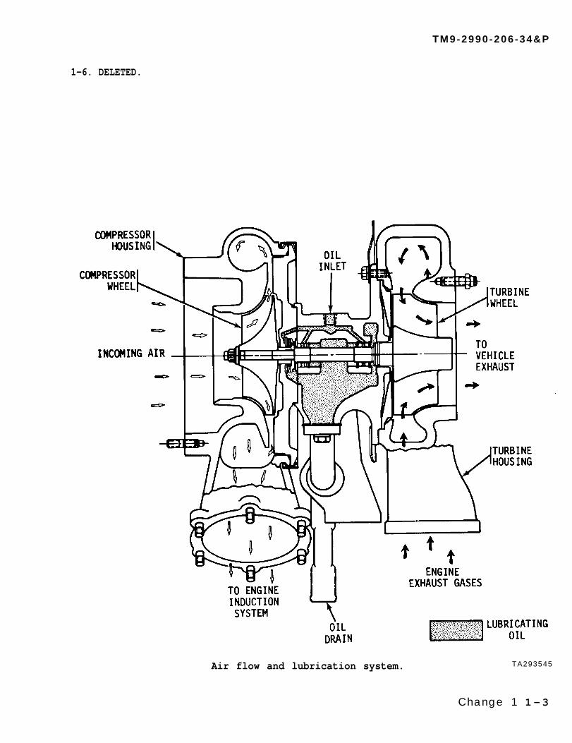
1-6. DELETED.
Air flow and lubrication system. TA293545
Change 1 1-3
TM9-2990-206-34&P

1-7 EQUIPMENT DATA.
a. General.
Manufacturer . . . . . . . . . . . . . . . . . . . . . . . . . . . . . . . . . . . . . . . AiResearch Industrial DivisionModel . . . . . . . . . . . . . . . . . . . . . . . . . . . . . . . . . . . . . . . . . . . . . . . . . . . . . . . . . . . . . . . . . . . . . T18C01Mounting . . . . . . . . . . . . . . . . . . . . . . . . . . . . . . . . . . . . . . . . . . . . . . . . . . . . . . . . . . . . . . . . . Universal
b. Speci f icat ions.
Maximum revolutions per minute . . . . . . . . . . . . . . . . . . . . . . . . . . . . . . . . . . . . . . . . . . . . . . 65,000Diameter of compressor air inlet opening . . . . . . . . . . . . . . . . . . . . . . . 6.50 in. (165.1 mm)Diameter of compressor air outlet opening . . . . . . . . . . . . . . . . . . . . . . .3.50 in. (88.9mm)Diameter of each turbine exhaust inlet opening. . . . . . . . . . . . . . . . .3.00 in. (76.2mm)Diameter of turbine exhaust outlet opening . . . . . . . . . . . . . . . . . . . . .4.25 in. (107.9 mm)Oil inlet pressure to center housing . . . . . . . . . . . . . . . . 40 to 70 psi (276 to 483 kPa)Oil outlet pressure from center housing . . . . . . . . . . . . . . . . . . . . . . . .crankcase pressure
1-8. IDENTIFICATION PLATE.
The turbosupercharger identificationplate is located on the backplate.
TA097804
1-4
TM 9-2990-206-34&P
CHAPTER 2 TM 9-2990-206-34&P
MAINTENANCE INSTRUCTIONS
Section 1. TROUBLESHOOTING
2-1. GENERAL.
a. Purpose. These troubleshootinginstructions are to be used after theturbosupercharger has been removed fromthe engine.
(1) These instructions will beused to make sure the reasons given onthe repair tag are correct, and to findout if there are other problems with theturbosupercharger.
(2) If no repair tag is attached,the instructions can be used to find outwhat is wrong so it can be repaired.
b. Inspection. Inspect the turbo-supercharger for the problems listedbelow, and then go to the Trouble-shooting Table to find out the causeand what corrective action to take.
2-2. INSPECTION.
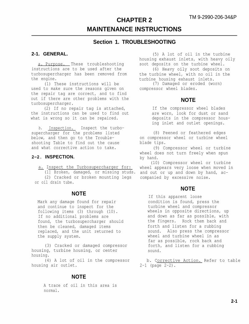
(5) A lot of oil in the turbinehousing exhaust inlets, with heavy oilysoot deposits on the turbine wheel.
(6) Heavy oily soot deposits onthe turbine wheel, with no oil in theturbine housing exhaust inlets.
(7) Damaged or eroded (worn)compressor wheel blades.
NOTEIf the compressor wheel bladesare worn, look for dust or sanddeposits in the compressor hous-ing inlet and outlet openings.
(8) Peened or feathered edgeson compressor wheel or turbine wheelblade tips.
(9) Compressor wheel or turbinewheel does not turn freely when spunby hand.
(10) Compressor wheel or turbinewheel appears very loose when moved ina. Inspect the Turbosupercharger for:
(1] Broken, damaged, or missing studs. and out or up and down by hand, ac-(2) Cracked or broken mounting legs
or oil drain tube.
NOTEMark any damage found for repairand continue to inspect for thefollowing items (3) through (10).If no additional problems arefound, the turbosupercharger shouldthen be cleaned, damaged itemsreplaced, and the unit returned tothe supply system.
(3) Cracked or damaged compressorhousing, turbine housing, or centerhousing.
(4) A lot of oil in the compressorhousing air outlet.
NOTEA trace of oil in this area isnormal.
companied by excessive noise.
NOTEIf this apparent loosecondition is found, press theturbine wheel and compressorwheels in opposite directions, upand down as far as possible, withthe fingers. Rock them back andforth and listen for a rubbingsound. Also press the compressorwheel and turbine wheel in asfar as possible, rock back andforth, and listen for a rubbingsound.
b. Corrective Action. Refer to table2-1 (page 2-2).
2-1

TM 9-2990-206-34&P
Table 2-1. Troubleshooting
PROBLEM
PROBABLE CAUSE
CORRECTIVE ACTION
1. A lot of oil in the compressor housing air outlet.
Worn or damaged spacer rings.
Disassemble and repair turbosupercharger. Refer to page 3-1.
2. A lot of oil in the turbine housing exhaust inlets, with heavy oily sootdeposits on the turbine wheel.
Worn engine piston rings and/or bearings.
Continue the troubleshooting outlined below. If no other problemsare found, clean the turbosupercharger and return to the supplysystem.
3. Heavy, oily soot deposits on the turbine wheel, with no oil in the turbinehousing exhaust inlets.
Worn or damaged seal ring.
NOTEHeavy soot deposits are generally caused by excessiveengine idling or poor combustion.
Disassemble and repair turbosupercharger. Refer to page 3-1.
4. Damaged or worn compressor wheel blades.
Foreign object striking blades or leaking engine induction system.
Disassemble and repair turbosupercharger. Refer to page 3-1.
5. Peened or feathered edges on compressor wheel or turbine wheel blade tips.
Worn sleeve bearings.
Disassemble and repair turbosupercharger. Refer to page 3-1.
6. Compressor wheel and turbine wheels do not turn freely when spun by hand.
Damaged compressor wheel or turbine wheel. Excessive dirt build-up incompressor housing or turbine housing. Excessive carbon build-upbehind compressor wheel.
Disassemble and repair turbosupercharger. Refer to page 3-1.
2-2
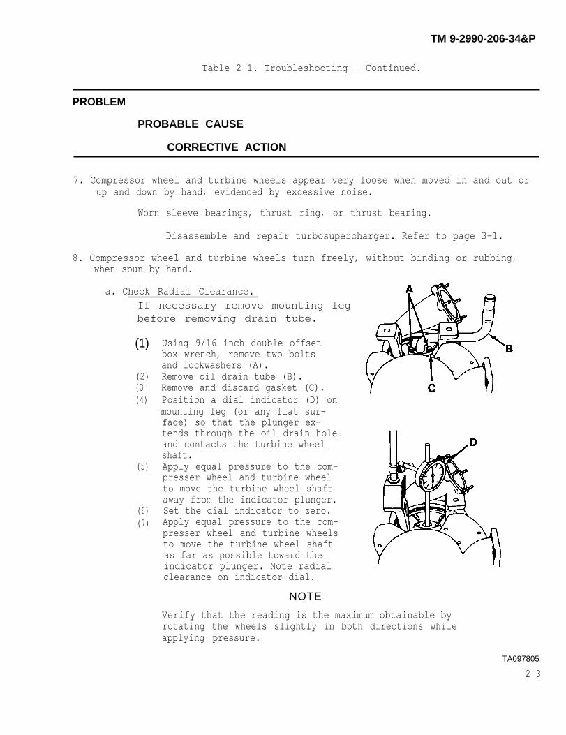
Table 2-1. Troubleshooting - Continued.
PROBLEM
PROBABLE CAUSE
CORRECTIVE ACTION
7. Compressor wheel and turbine wheels appear very loose when moved in and out orup and down by hand, evidenced by excessive noise.
Worn sleeve bearings, thrust ring, or thrust bearing.
Disassemble and repair turbosupercharger. Refer to page 3-1.
8. Compressor wheel and turbine wheels turn freely, without binding or rubbing,when spun by hand.
a. Check Radial Clearance.If necessary remove mounting legbefore removing drain tube.
(1)
(2)(3 )(4)
(5)
(6)(7)
Using 9/16 inch double offsetbox wrench, remove two boltsand lockwashers (A).Remove oil drain tube (B).Remove and discard gasket (C).Position a dial indicator (D) onmounting leg (or any flat sur-face) so that the plunger ex-tends through the oil drain holeand contacts the turbine wheelshaft.Apply equal pressure to the com-presser wheel and turbine wheelto move the turbine wheel shaftaway from the indicator plunger.Set the dial indicator to zero.Apply equal pressure to the com-presser wheel and turbine wheelsto move the turbine wheel shaftas far as possible toward theindicator plunger. Note radialclearance on indicator dial.
NOTE
Verify that the reading is the maximum obtainable byrotating the wheels slightly in both directions whileapplying pressure.
TA097805
2-3
TM 9-2990-206-34&P

Table 2-1. Troubleshooting - Continued.
(8)
(9)(l0)
(11)
Apply equal pressure to the compressor wheel and turbine wheelsto move the turbine wheel shaft as far as possible away fromthe indicator plunger. The indicator pointer should return tozero.Repeat steps (5) through (8) to verify the indicator reading.If the maximum radial clearance is less than 0.003 inch(0.076 mm) or greater than 0.006 inch (O. 152 mm), repair theturbosupercharger. Refer to page 3-1.If the maximum radial clearance is 0.003 inch (0.076 mm) to0.006 inch (0.152 mm), proceed to b. below.
b. Check End Play.
(1)
(2)
(3)(4)
(5)
(6)
Clean the turbine wheel hub. Attacha dial indicator (A) to the turbinehousing (or any flat surface) so thatthe plunger rests on the turbine wheelhub (B).Push the turbine wheel down as far aspossible.Set the dial indicator to zero.Pull the turbine wheel up as far aspossible. Note end play on indicatordial.Repeat steps (2) through (4) to verifythe indicator reading.If maximum end play is less than 0.004inch (0.102 mm) or greater than 0.009inch (0.229 mm), repair the turbo-supercharger. Refer to page 3-1.
(7) If maximum end play is 0.004 inch(0.102 mm) to 0.009 inch (0.229 mm),and no other damage is evident:
(a) Using new gasket (C), install oildrain tube (D).
(b) Secure oil drain tube with twobolts and lockwashers (E).Using 9/16 inch socket andO to 300 pound-inch, 1/2inch drive torque wrench,tighten bolts to 275 pound-inches (31 N-m).
(8) Clean unit and return to supply system.
TA007806
2-4
TM 9-2990-206-34&P
TM 9-2990-206-34&P
Section Il. GENERAL MAINTENANCE
2-3. GENERAL.
Special tools, repair parts, and equip-ment over and above those available tothe using organization are supplied todirect and general support units formaintaining and repairing the material.
2-4. COMMON TOOLS AND EQUIPMENT.
For authorized common tools and equip-ment refer to the Modified Table ofOrganization and Equipment (MTOE)applicable to your unit.
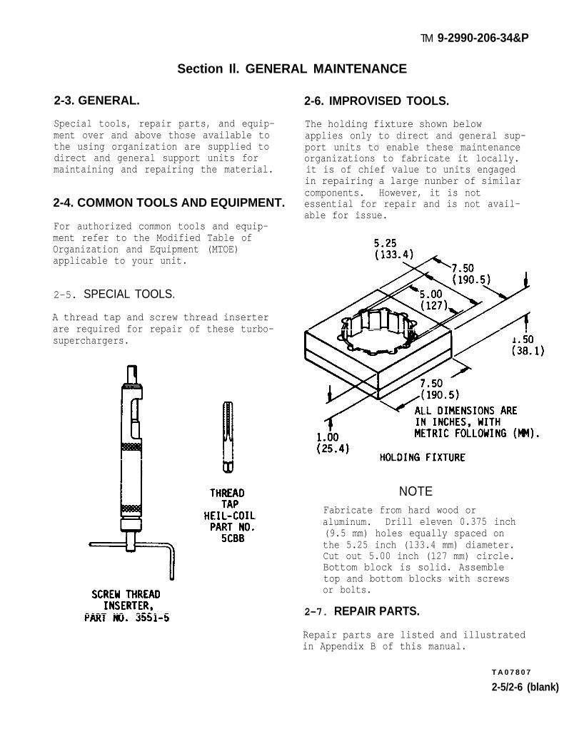
2-5. SPECIAL TOOLS.
A thread tap and screw thread inserterare required for repair of these turbo-superchargers.
2-6. IMPROVISED TOOLS.
The holding fixture shown belowapplies only to direct and general sup-port units to enable these maintenanceorganizations to fabricate it locally.it is of chief value to units engagedin repairing a large nunber of similarcomponents. However, it is notessential for repair and is not avail-able for issue.
NOTEFabricate from hard wood oraluminum. Drill eleven 0.375 inch(9.5 mm) holes equally spaced onthe 5.25 inch (133.4 mm) diameter.Cut out 5.00 inch (127 mm) circle.Bottom block is solid. Assembletop and bottom blocks with screwsor bolts.
2-7. REPAIR PARTS.
Repair parts are listed and illustratedin Appendix B of this manual.
T A 0 7 8 0 7
2-5/2-6 (blank)
CHAPTER 3
MAINTENANCE OPERATIONS
Section I. GENERAL
3-1. PURPOSE. pair, and reassembly of the turbosuper-charger. The step-by-step procedures
This chapter provides instructions for are accompanied by Illustrations whichdisassembly, cleaning, inspection, re- are keyed to the instructions.
Section Il. DISASSEMBLY
3-2. REPAIR EQUIPMENT.
Listed below are the shop equipment,common tools, expendable materials,and repair parts required for repairof the turbosupercharger.
a. Shop Equipment.(1) Arbor press and support
plates(2) Vise, 6-inch(3) Workbench
b. (common Tools.Box wrench, angular offset,
13/16 inch opening, 12 point(2) Box wrench, double offset,
9/16 inch opening, 6 or 12 point(3) Dial indicator(4) Extension, 5-inch, 1/2 inch
square drive(5) Hammer (plastic insert)(6) Hand file(7) Handle, socket wrench
(speeder), 16 inches long(8) Holding fixture (improvi seal)(9) Internal retaining ring
pliers, 7 inches long(10) Micrometer, 0.00 to 1.00 inch(11) Micrometer, 1.00 to 2.00 inch(12) Ratchet handle, 9-1/2 inches
long, 1/2 inch square drive(13) Scriber
(14) Socket, 7/16 inch opening(deep), 1/2 inch square drive, 6 or12 point
(15) Socket, 1/2 inch opening, 1/2inch square drive, 6 or 12 point
(16) Socket, 9/16 inch opening,1/2 inch square drive, 6 or 12 point
(17) Stud remover and setter, 1/2inch drive, 1/4 to 3/4 inch diameter
(18) Telescope gage, 0.3125. to0.5000 inch
(19) Telescope gage, 0.5000 to0.7500 inch
(20) Telescope gage, 0.7500 to1.2500 inch
(21) Thickness gage (feeler),0.0015 to 0.025 inch blades
(22) Torque wrench, O to 300 pound-inches, 1/2 inch square drive
(23) Vernier calipers
c. Expendable Materials.(1) Drycleaning solvent (P-D-680,
Type II)(2) Corrosion inhibiting, heat-
cured, solid film lubricant (MIL-L-4601O)(3) Preservative general purpose
lubrication oil (VV-L-800)(4) Lint-free cloths
3-1
TM 9-2990-206-34&P
d. Repair Parts. Requisition PartsKit, Part No. 409448 (page B-9).
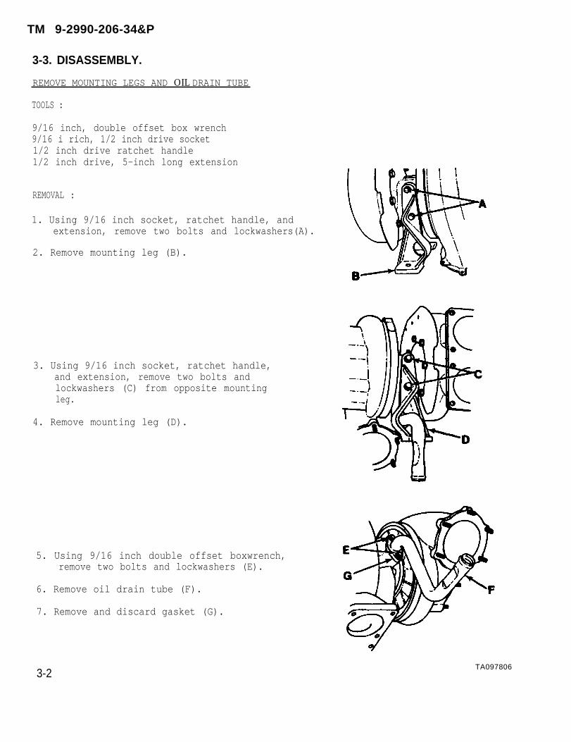
3-3. DISASSEMBLY.
REMOVE MOUNTING LEGS AND OIL DRAIN TUBE
TOOLS :
9/16 inch, double offset box wrench9/16 i rich, 1/2 inch drive socket1/2 inch drive ratchet handle1/2 inch drive, 5-inch long extension
REMOVAL :
1. Using 9/16 inch socket, ratchet handle, andextension, remove two bolts and lockwashers(A).
2. Remove mounting leg (B).
3. Using 9/16 inch socket, ratchet handle,and extension, remove two bolts andlockwashers (C) from opposite mountingleg.
4. Remove mounting leg (D).
5. Using 9/16 inch double offset boxwrench,remove two bolts and lockwashers (E).
6. Remove oil drain tube (F).
7. Remove and discard gasket (G).
3-2
TM 9-2990-206-34&P
TA097806

TM 9-2990-206-34&P
DISASSEMBLY-Continued.
REMOVE COMPRESSOR HOUSING
TOOLS:
Scriber7/16 inch, 1/2 inch drive, deep socketSocket wrench handle (speeder)
REMOVAL:
1. Using scriber, scribe alinement markson compressor housing (A), clamp (B),and backplate (C). If your tur-bosupercharger is a newer model,alinement marks will be cast into theflanges of the compressor and bearinghousings. Take careful note of thealinement marks to ensure properhousing alinement during assembly.
2. Using 7/16 inch socket and speeder,loosen nut (D) and move clamp (B)toward center housing (E).
Lift compressor housing carefullyto prevent damage to compressorwheel.
3. Remove compressor housing (A).
4. Remove and discard preformed packing(“0” ring) (F).
5. Remove clamp (B).
TA293542
C h a n g e 1 3 - 3
C A U T I O N

TM 9-2990-206-34&P
DISASSEMBLY—Continued.
REMOVE HEAT SHIELD AND CENTER HOUSING
TOOLS :
Scriber9/16 inch, double offset box wrench
REMOVAL :
1. Using scriber,center housing
2. On part number
scribe alinement marks on(A) and turbine housing (B).
11669107-1 and 11669107-2turbosuperchargers only, scribe alinementmarks on heat shield (D) and turbine housing(B).
3. Using 9/16 inch double offset box wrench,remove eight bolts and lockwashers (C).
4. Remove heat shield (D).
5. Lift center housing (A) with compressorwheel and turbine wheel from turbine hous-ing (B).
6. Remove six nuts (E) from engine exhaustmounting studs on turbine housing.
T A 2 9 3 6 S 6
3-4 Change 1

TM 9-2990-206-34&P
DISASSEMBLY—Continued.
REMOVE IMPELLER NUT (COMPRESSOR WHEEL NUT)
TOOLS:
13/16 inch, angular offset box wrench, 12 point1/2 inch, 1/2 inch drive socket, 12 point1/2 inch drive ratchet handleHolding fixture (improvised)
REMOVAL :
1. Place a 13/16 inch angular 12 point boxwrench in vise. Position wrench tohold turbine wheel hub.
2. Place turbine wheel hub in box wrench andhold in position (A).
3. Using 1/2 inch socket and ratchet handle (B)remove compressor wheel nut (C) from turbinewheel shaft.
4. On turbine wheel hubs that cannot be heldwith a box wrench (because of factorybalancing), use improvised holding fixture(D) to keep turbine wheel from turning.Refer to page 2-5 for fabrication instruc-tions.
5. Using 1/2 inch socket and ratchet handle (B),remove nut (C) from turbine wheel shaft.
3-5

DISASSEMBLY—Continued.
REMOVE COMPRESSOR WHEEL , TURBINE WHEEL, AND SHROUDWHEEL (SHROUD)
TOOLS :
Arbor pressSupport platesWood block
REMOVAL :
1. Place center housing (A) in arbor press (B),with turbine wheel protected by suitablesupport plates (C) and wood block (D).
2. Press turbine wheel shaft (E) until turbinewheel (F) drops on wood block (D).
3. Lift arbor and remove compressor wheel (G).Remove center housing and turbine wheel fromarbor press.
4. Remove turbine wheel (F) and shroud (H) fromcenter housing (A).
3-6
TM 9-2990-206-34&P
T A 0 9 7 8 1 2

DISASSEMBLY—Continued.
REMOVE SEAL RING, BACKPLATE, AND THRUST SPACER
TOOLS:
9/16 inch, double offset box wrenchPlastic insert hammer
REMOVAL:
1. Using fingers,from groove in
remove and discard seal ring (A)turbine wheel shaft (B).
2. Using 9/16 inch box wrench, remove four boltsand flat washers (C) from center housing.
3. Tap the backplatehammer and remove(E).
(D) with a plastic insertit from the center housing
4. Remove thrust spacer (F) from backplate (D).
5. Us;ing fingers, remove and discard two spacerrings (G) from thrust spacer (F).
TA097813
3-7
TM 9-2990-206-34&P

TM 9-2990-206-34&P
DISASSEMBLY—Continued.
REMOVE THRUST RING, THRUST BEARING, SLEEVEBEARING, AND THRUST MASHER
REMOVAL:
1. Remove thrust ring (A) .
2. Remove and discard ring seal (“O” ring) (B).
3. Remove and discard thrust bearing (C).
4. Remove and discard sleeve bearing (D) fromcenter housing bore.
5. Remove and discard thrust washer (E) fromhousing bore.
TAO978133-8
TM 9-2990-206-34&P
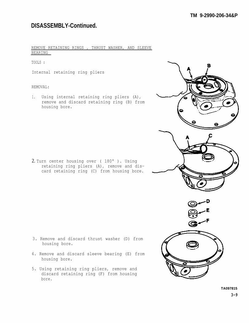
REMOVE RETAINING RINGS , THRUST WASHER, AND SLEEVEBEARING
TOOLS :
Internal retaining ring pliers
REMOVAL:
1. Using internal retaining ring pliers (A),remove and discard retaining ring (B) fromhousing bore.
2. Turn center housing over ( 180° ). Usingretaining ring pliers (A), remove and dis-card retaining ring (C) from housing bore.
3. Remove and discard thrust washer (D) fromhousing bore.
4. Remove and discard sleeve bearing (E) fromhousing bore.
5. Using retaining ring pliers, remove anddiscard retaining ring (F) from housingbore.
TA097815
3-9
DISASSEMBLY-Continued.

TM 9-2990-206-34&P
DISASSEMBLY—Continued.
REMOVE DUST DETECTOR COVER, PACKING WITH RETAINER,CHAIN FASTENER, CHAIN “S” HOOK, AND CHAIN
Tools:1/2 inch, 1/2 inch drive socket1/2 inch drive ratchet handle
NOTE
This procedure applies to“clean air” turbosuperchar-ger only.
REMOVAL :
1. Using 1/2 inch socket and ratchethandle, remove three cap screws (A),two flat washers (B), and packingwith retainer (C). Discard packingwith retainer.
2. Remove chain fastener (D), chain “S”hook (E), and chain (F) as anassembly.
NOTE
It will not be necessary todisassemble the chain fast-ener, chain “S” hook, andchain unless one or more ofthese parts shows signs ofwear or damage.
3. Remove dust detector cover (G).
3 - 1 0 Change 1TA293543

DISASSEMBLY—Continued.
REMOVE PREFORMED PACKINGS, FILTER RETAINING STRAP I
AND FILTER FROM DUST DETECTOR COVER
NOTE
This procedure applies to“clean air” turbosuper-charger only.
REMOVAL:
1. Remove filter retaining strap (A) andfilter (6).
2. Remove and discard three preformedpackings (C) from underside of dustdetector cover.
REMOVE COMPRESSOR COVER INLET AND OUTLET ADAPTERSAND PREFORMED PACKINGS
TOOLS:
9/16 inch offset box wrench5/8 inch offset box wrench
REMOVAL:
1. Using 5/8 inch box wrench, removecompressor cover inlet adapter (A).
2. Using 9/16 inch box wrench, removecompressor cover outlet adapter (B).
3. Remove and discard two preformedpackings (C).
TA293544
Change 1 3-10.1
TM 9-2990-206-34&P
TM 9-2990-206-34&P
Section Ill. CLEANING, INSPECTION, AND REPAIR
3-4. CLEANING.
W A R N I N G —
Particles blown by compressedair are hazardous. Make certainthe air stream is not directedat any person. Protect eyesand face with appropriate shields.
Remove foreign material accumulationsfrom exterior surfaces. Remove anyremaining foreign material using aclean cloth moistened in drycleaningsolvent (P-D-680, Type II). BlOW drywith compressed air, or wipe dry witha clean cloth. Clean all oil holeswith probes. Probe the turbine end ofthe center housing to remove all carbon-ized oil.
CAUTION
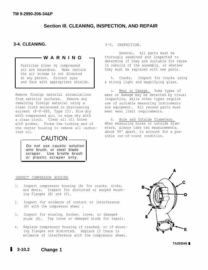
INSPECT COMPRESSOR HOUSING
1.
2.
3.
4.
3-5. INSPECTION.
General. All parts must bethorougly examined and inspected todetermine if they are suitable for reusein rebuild of the assembly, or whetherthey must be replaced with new parts.
b. Cracks. Inspect for cracks usinga strong light and magnifying glass.
c. Wear or Damage. Some types ofwear or damage may be detected by visualinspection, while other types requireuse of suitable measuring instrumentsand equipment. All reused parts mustmeet wear limit requirements.
d. Bore and Outside Diameters.When measuring bores or outside diam-eters, always take two measurements,about 90° apart, to account for a pos-sible out-of-round condition.
Inspect compressor housing (A) for cracks, nicks,and dents. Inspect for distorted or warped mount-ing flanges (B) and (C).
Inspect for evidence of contact or interference(D) with the compressor wheel .
Inspect for missing, broken, loose, or damagedstuds (E). Tag loose or damaged studs for repair.
Replace compressor housing if cracked, or if mount-ing flanges are distorted. Replace if there isevidence of interference with the compressor wheel.
TA293546
3-10.2 Change 1
Do not use caustic solut ionwire brush, or steel bladescraper. Use brist le brusho r p l as t i c sc rape r on l y .

INSPECTION-Continued.
INSPECT CLAMP
1. Inspect clamp (A) for cracks or separated welds (B).
2. Inspect nut (C) and yoke stud (D) for thread damage,
3. Replace cracked or damaged clamp or nut.
INSPECT MOUNTING LEGS AND OIL DRAIN TUBE
1. Inspect mounting legs (E) and oil drain tube (F)for cracks. Look for bent or crushed drain tube (F).
2. Inspect weld at tube and flange joint.
3. Replace cracked mounting legs. Replace cracked,bent, or crushed oil drain tube.
INSPECT HEAT SHIELD
1. Inspect heat shield (G) for cracks and deformation.Tag deformed heat shield for possible repair.
2. Replace cracked heat shield
INSPECT TURBINE HOUSING
1.
2.
3.
4.
Inspect turbine housingfor distorted or warped(K), and (L).
Inspect for evidence ofwith the turbine wheel.
(H) for cracks. Lookmounting flanges (J),
contact or interference (M)
Inspect for missing, broken, loose, or damaged studs(N). Tag loose or damaged studs for repair. Inspecttapped holes (P) for thread damage.
Replace turbine housing if cracked, or if mountingflanges are distorted.
TM 9-2990-206-34&P
TA097817
3-11
TM 9-2990-206-34&P
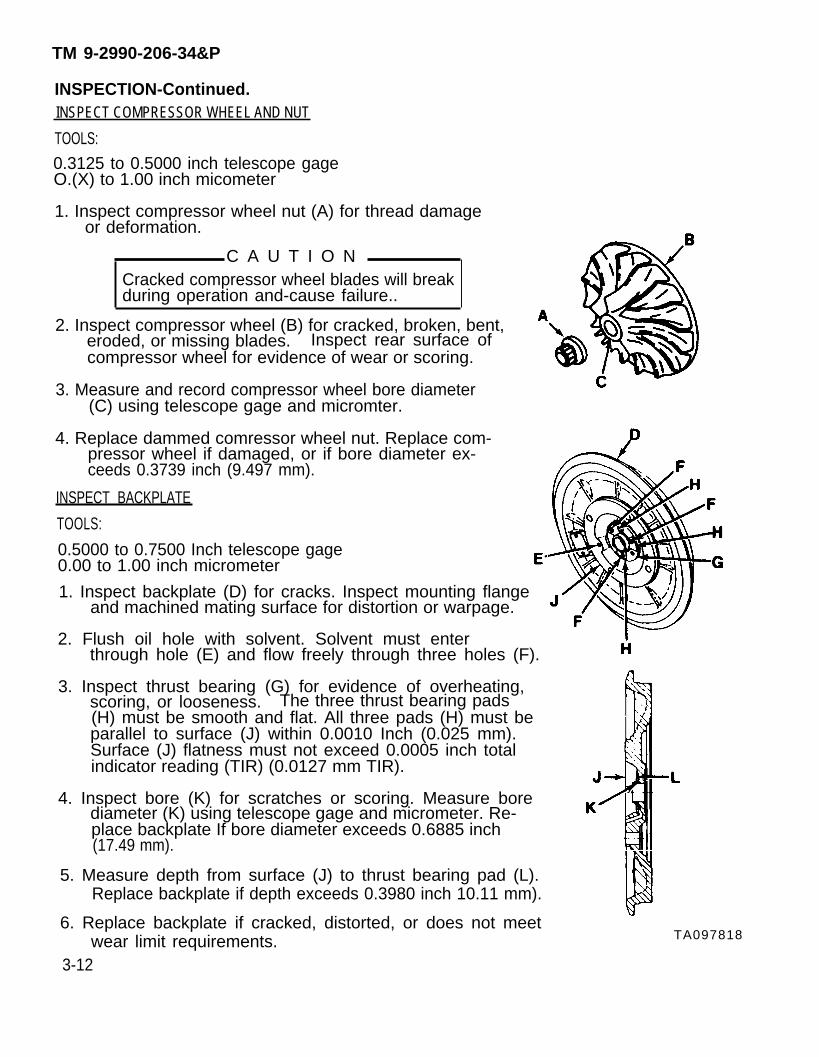
INSPECTION-Continued.INSPECT COMPRESSOR WHEEL AND NUT
TOOLS:
0.3125 to 0.5000 inch telescope gageO.(X) to 1.00 inch micometer
1. Inspect compressor wheel nut (A) for thread damageor deformation.
Cracked compressor wheel blades will breakduring operation and-cause failure..
2. Inspect compressor wheel (B) for cracked, broken, bent, eroded, or missing blades. Inspect rear surface ofcompressor wheel for evidence of wear or scoring.
3. Measure and record compressor wheel bore diameter(C) using telescope gage and micromter.
4. Replace dammed comressor wheel nut. Replace com-
C A U T I O N
pressor wheel if damaged, or if bore diameter ex-ceeds 0.3739 inch (9.497 mm).
INSPECT BACKPLATE
TOOLS:
0.5000 to 0.7500 Inch telescope gage0.00 to 1.00 inch micrometer
1. Inspect backplate (D) for cracks. Inspect mounting flangeand machined mating surface for distortion or warpage.
2. Flush oil hole with solvent. Solvent must enterthrough hole (E) and flow freely through three holes (F).
3. Inspect thrust bearing (G) for evidence of overheating,scoring, or looseness. The three thrust bearing pads(H) must be smooth and flat. All three pads (H) must beparallel to surface (J) within 0.0010 Inch (0.025 mm).Surface (J) flatness must not exceed 0.0005 inch totalindicator reading (TIR) (0.0127 mm TIR).
4. Inspect bore (K) for scratches or scoring. Measure borediameter (K) using telescope gage and micrometer. Re-place backplate If bore diameter exceeds 0.6885 inch(17.49 mm).
5. Measure depth from surface (J) to thrust bearing pad (L).Replace backplate if depth exceeds 0.3980 inch 10.11 mm).
6. Replace backplate if cracked, distorted, or does not meetwear limit requirements.
3-12
TA097818
INSPECTION-Continued.
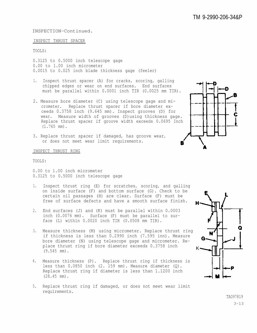
INSPECT THRUST SPACER
TOOLS:
0.3125 to 0.5000 inch telescope gage0.00 to 1.00 inch micrometer0.0015 to 0.025 inch blade thickness gage (feeler)
1. Inspect thrust spacer (A) for cracks, scoring, gallingchipped edges or wear on end surfaces. End surfacesmust be parallel within 0.0001 inch TIR (0.0025 mm TIR).
2. Measure bore diameter (C) using telescope gage and mi-crometer. Replace thrust spacer if bore diameter ex-ceeds 0.3758 inch (9.645 mm). Inspect grooves (D) forwear. Measure width of grooves (D)using thickness gage.Replace thrust spacer if groove width exceeds 0.0695 Inch(1.765 mm).
3. Replace thrust spacer if damaged, has groove wear,or does not meet wear limit requirements.
INSPECT THRUST RING
TOOLS:
0.00 to 1.00 inch micrometer0.3125 to 0.5000 inch telescope gage
1.
2.
3.
4.
5.
Inspect thrust ring (E) for scratches, scoring, and gallingon inside surface (F) and bottom surface (G). Check to becertain oil passages (H) are clear. Surface (F) must befree of surface defects and have a smooth surface finish.
End surfaces (J) and (K) must be parallel within 0.0003inch (0.0076 mm). Surface (F) must be parallel to sur-face (L) within 0.0020 inch TIR (0.0508 mm TIR).
Measure thickness (M) using micrometer. Replace thrust ringif thickness is less than 0.2990 inch (7.595 inn). Measure bore diameter (N) using telescope gage and micrometer. Re-place thrust ring if bore diameter exceeds 0.3758 inch(9.545 mm). K
Measure thickness (P). Replace thrust ring if thickness isless than 0.0850 inch (2. 159 mm). Measure diameter (Q).Replace thrust ring if diameter is less than 1.1200 inch(28.45 mm).
Replace thrust ring if damaged, or does not meet wear limitrequirements.
TAO978193-13
TM 9-2990-206-34&P
INSPECTION—Continued.
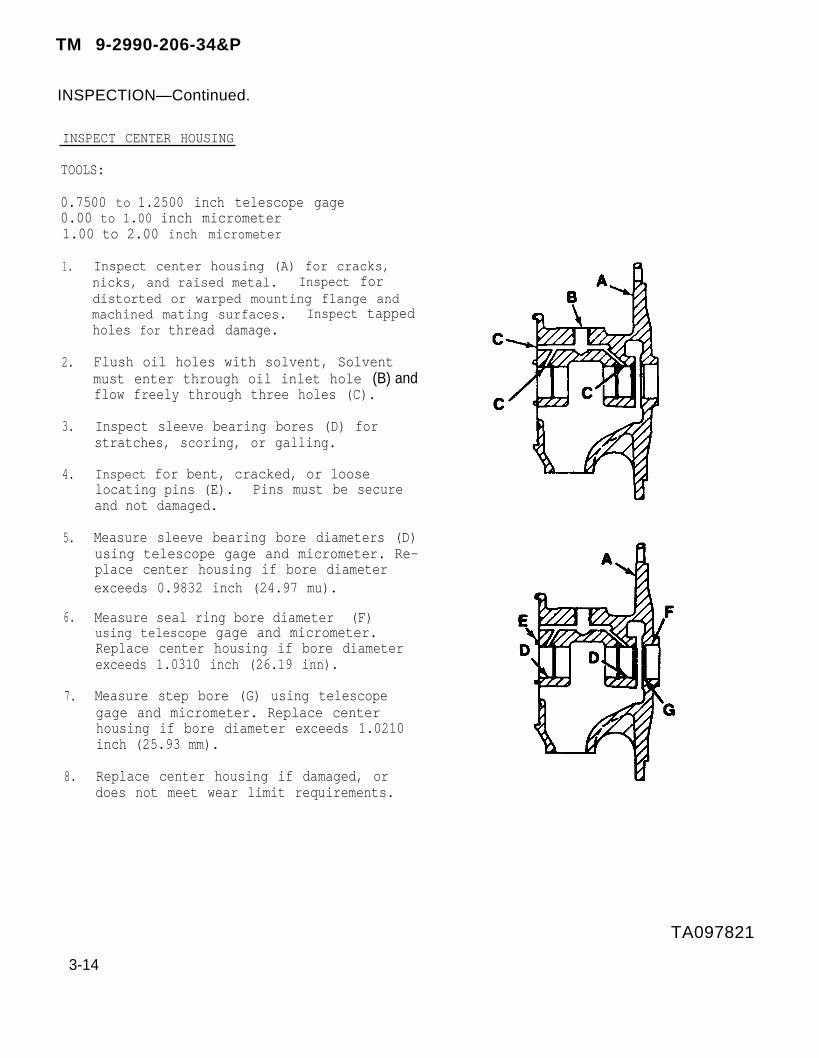
INSPECT CENTER HOUSING
TOOLS:
0.7500 to 1.2500 inch telescope gage0.00 to 1.00 inch micrometer1.00 to 2.00 inch micrometer
1.
2.
3.
4.
5.
6.
7.
8.
Inspect center housing (A) for cracks,nicks, and raised metal. Inspect fordistorted or warped mounting flange andmachined mating surfaces. Inspect tappedholes for thread damage.
Flush oil holes with solvent, Solventmust enter through oil inlet hole (B) andflow freely through three holes (C).
Inspect sleeve bearing bores (D) forstratches, scoring, or galling.
Inspect for bent, cracked, or looselocating pins (E). Pins must be secureand not damaged.
Measure sleeve bearing bore diameters (D)using telescope gage and micrometer. Re-place center housing if bore diameterexceeds 0.9832 inch (24.97 mu).
Measure seal ring bore diameter (F)using telescope gage and micrometer.Replace center housing if bore diameterexceeds 1.0310 inch (26.19 inn).
Measure step bore (G) using telescopegage and micrometer. Replace centerhousing if bore diameter exceeds 1.0210inch (25.93 mm).
Replace center housing if damaged, ordoes not meet wear limit requirements.
3-14
TM 9-2990-206-34&P
TA097821

INSPECTION-Continued.
INSPECT SHROUD
1. Inspect shroud (A) for cracks, nicks, andraised metal.
2. Inspect mating flange for distortion. Inspect flatface of shroud for evidence of rubbing or scoringfrom the turbine wheel.
3. Replace damaged shroud.
INSPECT TURBINE WHEEL
TOOLS:
0.00 to 1.00 inch micrometer0.0015 to O.025 inch blade thickness gage (feeler)Vernier calipers
1.
2.
3.
4.
5.
6.
CAUTION
Cracked turbine wheel blades will breakduring operation and cause failure.
Inspect turbine wheel (B) for cracked, broken, bent,eroded, or missing blades. Inspect shaft for cracks,scratches, or scoring. Inspect bearing journals andthreads for damage. Inspect rear surface of turbinewheel for evidence of wear or scoring. Inspectseal ring groove (C) for wear.
Inspect blade tips for feather-edge or tears.
Measure blade tips (D) with micrometer. Replaceturbine wheel if damaged, or if blade thickness isless than 0.025 inch (0.635 mm).
Measure seal ring groove (C) width and diameterusing thickness gage and vernier calipers. Replaceturbine wheel if groove width exceeds 0.0685 inch(1.7399mm) or groove diameter is less than 0.8600inch (21.84 mm).
Measure shaft bearing journals (E) using micrometer.Replace turbine wheel if diameters are less than0.6250 inch (15.875 mm).
Measure shaft hub diameter (F) using micrometer.Replace turbine wheel if diameter is less than0.9950 inch (25.273 mm).
TA097821
3-15
TM 9-2990-206-34&P
INSPECTION-Continued.
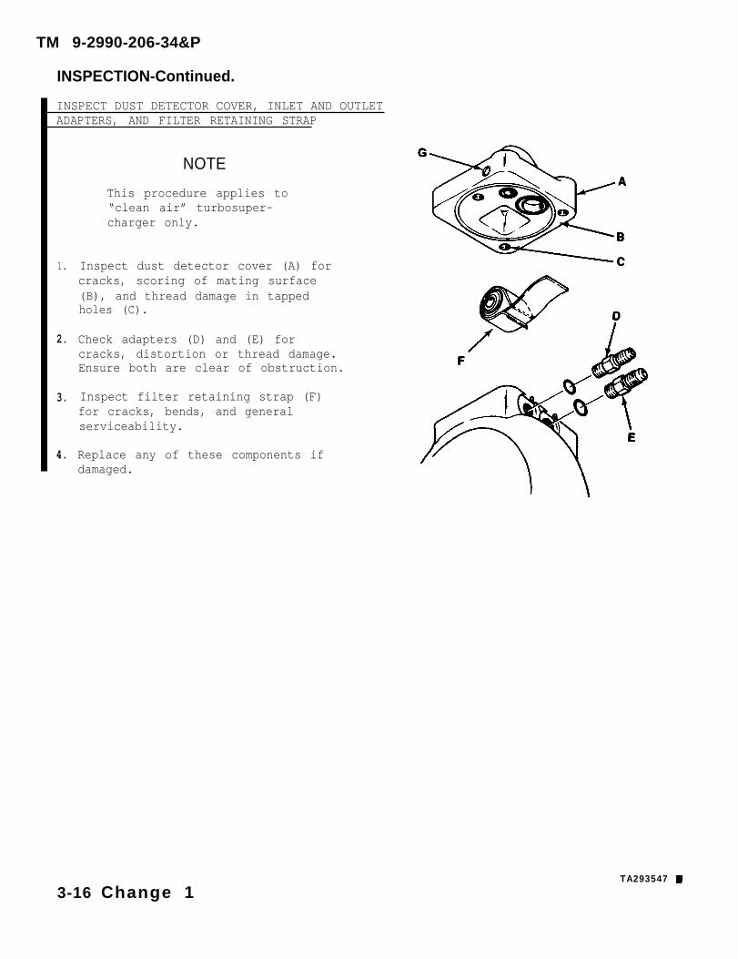
INSPECT DUST DETECTOR COVER, INLET AND OUTLETADAPTERS, AND FILTER RETAINING STRAP
NOTE
This procedure applies to“clean air” turbosuper-charger only.
1.
2.
3.
4.
Inspect dust detector cover (A) forcracks, scoring of mating surface(B), and thread damage in tappedholes (C).
Check adapters (D) and (E) forcracks, distortion or thread damage.Ensure both are clear of obstruction.
Inspect filter retaining strap (F)for cracks, bends, and generalserviceability.
Replace any of these components ifdamaged.
TA293547
3-16 Change 1
TM 9-2990-206-34&P
3-6. REPAIR.
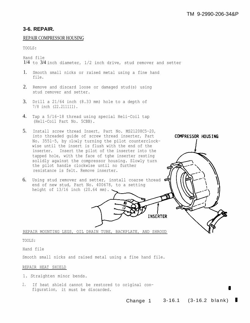
REPAIR COMPRESSOR HOUSING
TOOLS:
Hand file1/4
1.
2.
3.
4.
5.
6.
to 3/4 inch diameter, 1/2 inch drive, stud remover and setter
Smooth small nicks or raised metal using a fine handfile.
Remove and discard loose or damaged stud(s) usingstud remover and setter.
Drill a 21/64 inch (8.33 mm) hole to a depth of7/8 inch (22.211111).
Tap a 5/16-18 thread using special Heli-Coil tap(Heli-Coil Part No. 5CBB).
Install screw thread Insert, Part No. MS21208C5-20,into threaded guide of screw thread inserter, PartNo. 3551-5, by S1OWly turning the pilot counterclock-wise until the insert is flush with the end of theinserter. Insert the pilot of the inserter into thetapped hole, with the face of tghe inserter restingsolidly against the compressor housing. Slowly turnthe pilot handle clockwise until no furtherresistance is felt. Remove inserter.
Using stud remover and setter, install coarse threadend of new stud, Part No. 400678, to a settingheight of 13/16 inch (20.64 mm).
REPAIR MOUNTING LEGS, OIL DRAIN TUBE, BACKPLATE, AND SHROUD
TOOLS:
Hand file
Smooth small nicks and raised metal using a fine hand file.
REPAIR HEAT SHIELD
1. Straighten minor bends.
2. If heat shield cannot be restored to original con-figuration, it must be discarded.
Change 1 3-16.1 (3-16.2 blank)
TM 9-2990-206-34&P


REPAIR—Continued.
REPAIR TURBINE HOUSING
TOOLS :
Hand file1/4 to 3/4 inch diameter, 1/2 inch drive, studremover and setter
1. Smooth small nicks or raised metal usinga fine hand file.
2. Remove and discard loose or damagedstud(s) (A) using stud remover and setter.
3. Using stud remover and setter, installcoarse thread end of new stud, Part No.400602-1, to a setting height of 1.00inch (25.4 inn).
4. Repair damaged threads using a used3/8-16NC thread tap.
REPAIR CENTER HOUSING
TOOLS :
Hand file
1. Smooth small nicks or raised metal usinga fine hand file.
2. Repair damaged oil inlet opening threads(B) using a used 1/4 NPT thread tap.
3. Repair damaged mounting leg attachingthreads (C), backplate attaching threads(D), and oil drain tube attaching threads(E), using a used 3/8-16NC thread tap.
REPAIR CLAMP, COMPRESSOR WHEEL AND NUT, THRUST SPACER,THRUST RING, AND TURBINE WHEEL
1. No repairs are authorized for these parts.
2. Replace damaged components.
TM 9-2990-206-34&P
3 - 1 7TA097823
3 - 7 . G E N E R A L .
Section IV. ASSEMBLY
b e f o r e a s s e m b l y , c o a t a l l p a r t s w i t h al i g h t f i l m o f e n g i n e o i l ( O E / H D O ) .
Turbosuperchargers are precision productsand extreme care and cleanl iness must beexercised in all phases of assembly oper- 3-8 . PARTS KIT .a t i o n s t o i n s u r e s a t i s f a c t o r y p e r f o r m a n c e .D i r t a n d d u s t a r e a b r a s i v e . A f t e r c l e a n - Par ts K i t , Par t No. 409448 (page B-9) ,i n g , i n s p e c t i o n , a n d r e p a i r , a n d j u s t must be requ is i t ioned and used to
assemble the tu rbosupercharger .
3-9 ASSEMBLY.
INSTALL RETAINING RING.
TOOLS:
I n t e r n a l r e t a i n i n g r i n g p l i e r s
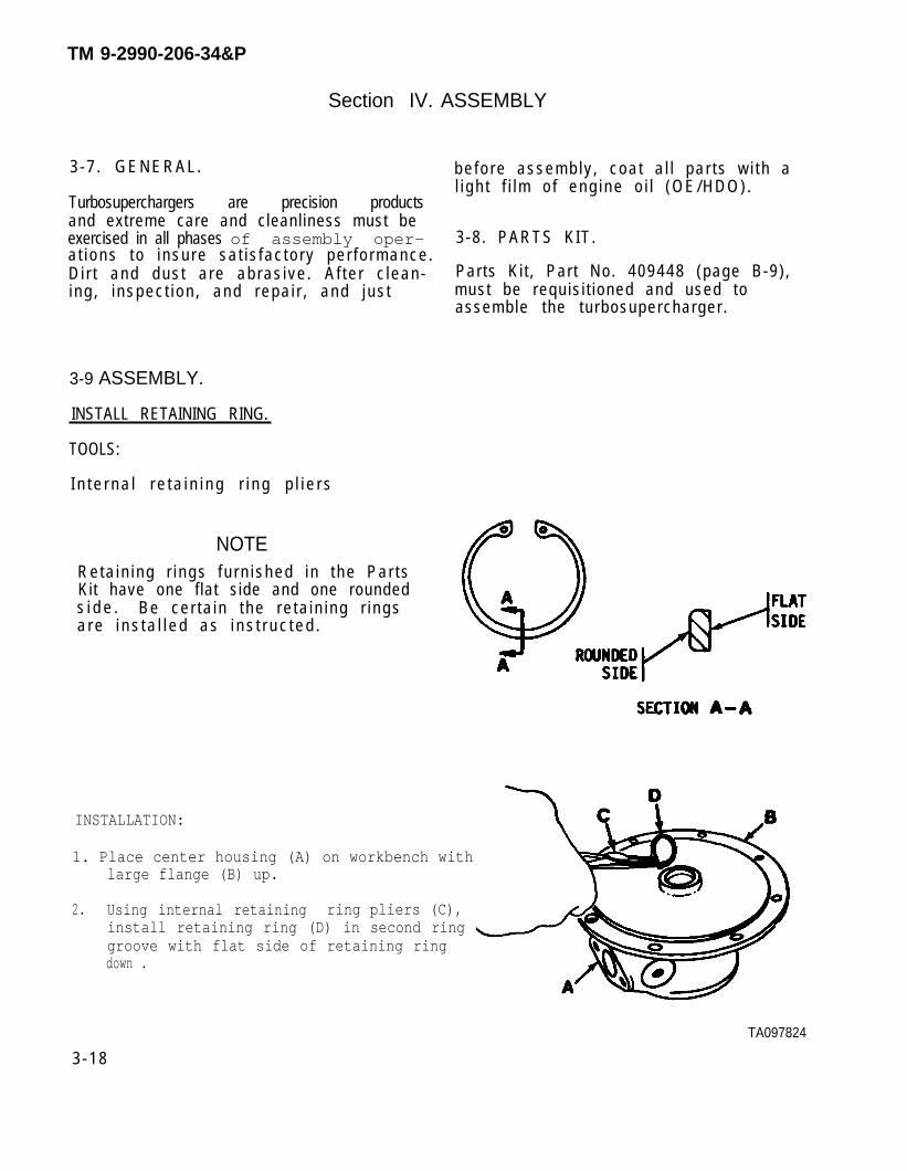
NOTER e t a i n i n g r i n g s f u r n i s h e d i n t h e P a r t sKit have one f lat side and one roundeds i d e . B e c e r t a i n t h e r e t a i n i n g r i n g sa r e i n s t a l l e d a s i n s t r u c t e d .
INSTALLATION:
1. Place center housing (A) on workbench withlarge flange (B) up.
2. Using internal retaining ring pliers (C),install retaining ring (D) in second ringgroove with flat side of retaining ringdown .
TA097824
3 - 1 8
TM 9-2990-206-34&P

ASSEMBLY–Continued.
INSTALL SLEEVE BEARINGS, THRUST WASHERS, ANDRETAINING RINGS
TOOLS :
Internal retaining ring pliers
INSTALLATION:
1. Install sleeve bearing (A) and thrust washer(B).
2. Using retaining ring pliers, install retain-ing ring (C) in top groove with rounded sideof retaining ring down.
3. Turn center housingtaining ring pliersring (E) in groove,
over (1800).(D), installwith flat si
Using re-retainingde down.
4. Install thrust washer (F) and sleevebearing (G) in center housing bore.
TA097825
3-19
TM 9-2990-206-34&P

TM 9-2990-206-34&P
ASSEMBLY-Continued.
INSTALL SEAL RING, SHROUD, TURBINE WHEEL, ANDTHRUST BEARING
INSTALLATION:
Use care when installing the seal ring
1.
2.
3.
Install seal ring (A) in groove on turbinewheel hub (B).
Install shroud (C)on turbine wheel (B) withoutside rounded surface toward flat side ofturbine wheel (B).
Install turbine wheel (B) (with shroud) oncenter housing (D). Gently push the turbinewheel and shroud toward center housing usinga rocking motion, until turbine wheel sealring enters center housing bore as far aspossible.
4. Hold assembled turbine wheel, shroud, andcenter housing (D) in upright position.Aline thrust bearing locating pin holeswith locating pins (E) in center housing(D) and install thrust bearing (F), withwear pad up.
TA097826
3-20
(A). It may break if spread more thannecessary to clear the hub.
ASSEMBLY—Continued.
INSTALL THRUST RING, “O” RING, SPACER RINGS,AND THRUST SPACER
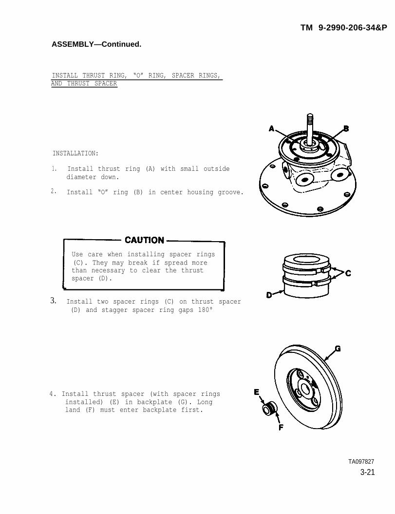
INSTALLATION:
1. Install thrust ring (A) with small outsidediameter down.
2. Install “O” ring (B) in center housing groove.
Use care when installing spacer rings(C). They may break if spread morethan necessary to clear the thrustspacer (D).
3. Install two spacer rings (C) on thrust spacer(D) and stagger spacer ring gaps 180°
4. Install thrust spacer (with spacer ringsinstalled) (E) in backplate (G). Longland (F) must enter backplate first.
TA097827
3-21
TM 9-2990-206-34&P

TM 9-2990-206-34&P
ASSEMBLY—Continued.
INSTALL BACKPLATE (WITH THRUST SPACER), COMPRESSORWHEEL, AND NUT
TOOLS :
9/16 inch, 1/2 inch drive socket3/16inch, angular offset box wrench, 12 point1/2 inch, 1/2 inch drive socket, 12 point1/2 inch drive, O to 300 pound-inches, torque wrench
INSTALLATION:
1.
2.
3.
4.
5.
6.
Hold thrust spacer (A) in position in back-plate (B) and install backplate on centerhousing (C). Install four flat washers andbolts (D) and tighten using 9/16 inch socketand torque wrench. Torque tighten to 275pound-inches (31 N-m).
Place a 13/16 inch angular 12 point boxwrench (E) in vise. Position wrenchto hold turbine wheel hub.
Place turbine wheel hub in box wrench (E)and hold in position. Install compressorwheel (F) on turbine wheel shaft. Installcompressor wheel nut (G).
Using torque wrench (H), torque tighten nutto 137 pound-inches (15.5 N-m) to seat thecompressor wheel against the thrust spacer (A).
Loosen compressor wheel nut two turns. Tightennut one turn and note drag torque (torque re-quired to turn nut before it seats on the com-presser wheel). Tighten nut to 45 pound-inches(5 N-m) above drag torque.
NOTEA sharp increase in torque will benoted when the nut bottoms againstthe compressor wheel.
Tighten nut to final position by pulling thewrench through an angle of llOO-beyond the 45pound-inches (5 Nom) torque point to attainproper shaft stretch.
3-22TA097828
ASSEMBLY—Continued.
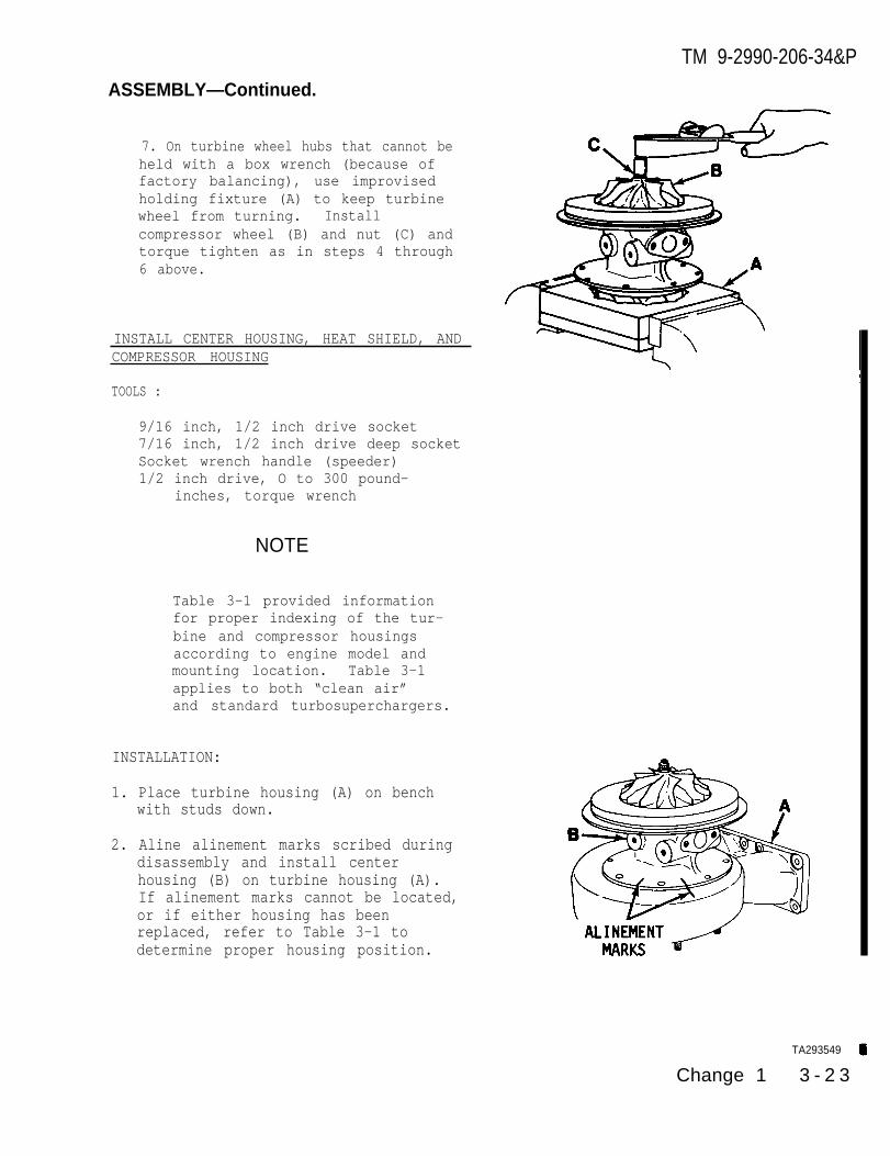
7. On turbine wheel hubs that cannot beheld with a box wrench (because offactory balancing), use improvisedholding fixture (A) to keep turbinewheel from turning. Installcompressor wheel (B) and nut (C) andtorque tighten as in steps 4 through6 above.
INSTALL CENTER HOUSING, HEAT SHIELD, ANDCOMPRESSOR HOUSING
TOOLS :
9/16 inch, 1/2 inch drive socket7/16 inch, 1/2 inch drive deep socketSocket wrench handle (speeder)1/2 inch drive, O to 300 pound-
inches, torque wrench
NOTE
Table 3-1 provided informationfor proper indexing of the tur-bine and compressor housingsaccording to engine model andmounting location. Table 3-1applies to both “clean air”and standard turbosuperchargers.
INSTALLATION:
1. Place turbine housing (A) on benchwith studs down.
2. Aline alinement marks scribed duringdisassembly and install centerhousing (B) on turbine housing (A).If alinement marks cannot be located,or if either housing has beenreplaced, refer to Table 3-1 todetermine proper housing position.
TA293549
Change 1 3 - 2 3
TM 9-2990-206-34&P

ASSEMBLY-Continued.
INSTALL CENTER HOUSING, HEAT SHIELD, ANDCOMPRESSOR HOUSING - CONTINUED
3.
4.
5.
6.
Aline alinement marks scribed duringdisassembly and install heat shield(c)o
NOTE
If the turbosupercharger isto be used on engine modelsAVDS-1790-2DR the heatshield is not used.
Apply a light coat of corrosion inhib-iting, heat cured, solid film lubri-cant (MIL-L-4601O) on bolts. Securecenter housing (B) and heat shield(C) to turbine housing (A) with eightlockwashers and bolts. Torquebolts to 275 pound-inches (31 N.m)using 9/16 inch socket and torquewrench.
Place clamp (0) over backplate (E)and on heat shield (F).
Install “O” ring (G) on backplate(E).
3 - 2 4 C h a n g e 1
TM 9-2990-206-34&P
TM 9-2990-206-34&P
ASSEMBLY—Continued.
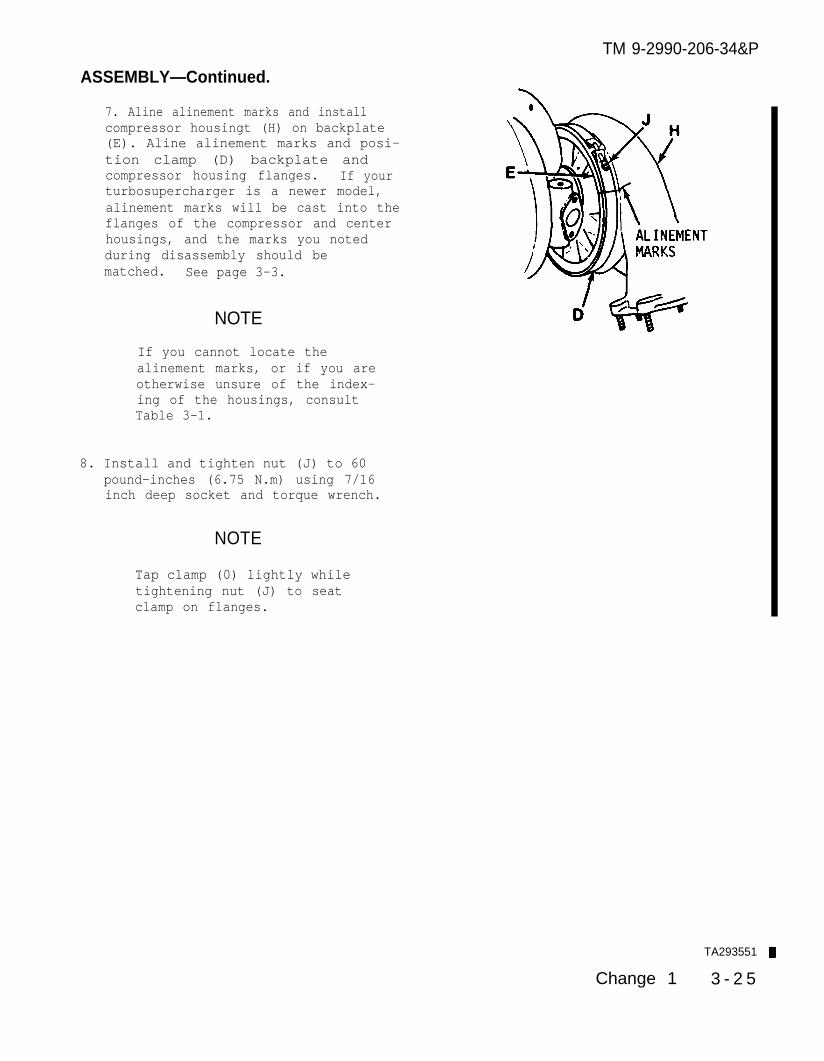
7. Aline alinement marks and installcompressor housingt (H) on backplate(E). Aline alinement marks and posi-tion clamp (D) backplate andcompressor housing flanges. If yourturbosupercharger is a newer model,alinement marks will be cast into theflanges of the compressor and centerhousings, and the marks you notedduring disassembly should bematched. See page 3-3.
NOTE
If you cannot locate thealinement marks, or if you areotherwise unsure of the index-ing of the housings, consultTable 3-1.
8. Install and tighten nut (J) to 60pound-inches (6.75 N.m) using 7/16inch deep socket and torque wrench.
NOTE
Tap clamp (0) lightly whiletightening nut (J) to seatclamp on flanges.
TA293551
Change 1 3 - 2 5
TM 9-2990-206-34&P
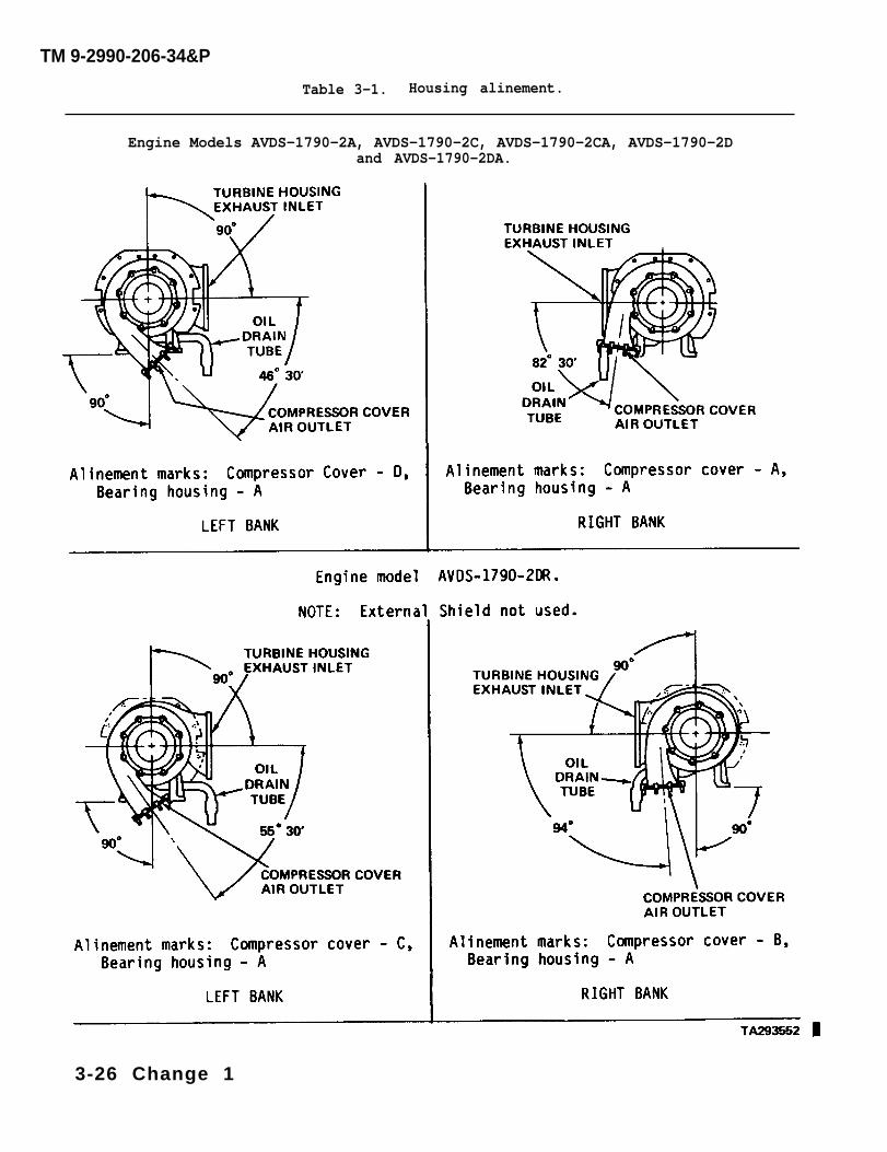
Table 3-1. Housing alinement.
Engine Models AVDS-1790-2A, AVDS-1790-2C, AVDS-1790-2CA, AVDS-1790-2Dand AVDS-1790-2DA.
3-26 Change 1
TM 9-2990-206-34&P
ASSEMBLY—Continued.
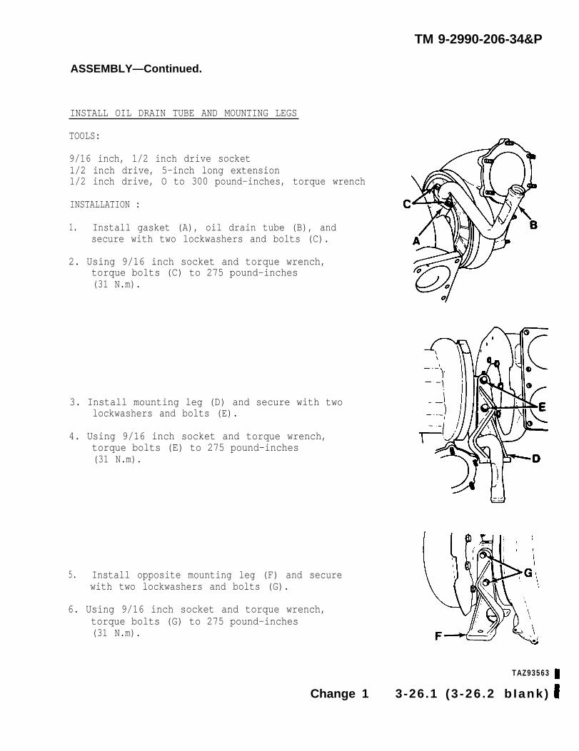
INSTALL OIL DRAIN TUBE AND MOUNTING LEGS
TOOLS:
9/16 inch, 1/2 inch drive socket1/2 inch drive, 5-inch long extension1/2 inch drive, O to 300 pound-inches, torque wrench
INSTALLATION :
1. Install gasket (A), oil drain tube (B), andsecure with two lockwashers and bolts (C).
2. Using 9/16 inch socket and torque wrench,torque bolts (C) to 275 pound-inches(31 N.m).
3. Install mounting leg (D) and secure with twolockwashers and bolts (E).
4. Using 9/16 inch socket and torque wrench,torque bolts (E) to 275 pound-inches(31 N.m).
5. Install opposite mounting leg (F) and securewith two lockwashers and bolts (G).
6. Using 9/16 inch socket and torque wrench,torque bolts (G) to 275 pound-inches(31 N.m).
TAZ93563
Change 1 3-26.1 (3 -26 .2 b Iank)

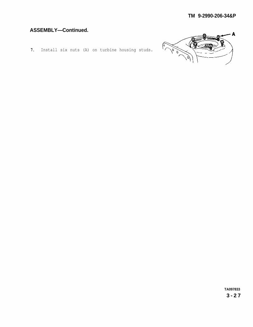
ASSEMBLY—Continued.
Install six nuts (A) on turbine housing studs.7.
TA097833
3 - 2 7
TM 9-2990-206-34&P

ASSEMBLY—Continued.
INSTALL COMPRESSOR HOUSING INLET AND OUTLETADAPTERS
TOOLS:
9/16 inch, 1/2 inch drive deep well socket5/8 inch, 1/2 inch drive deep well socket1/2 inch drive, O to 300 pound-inches torque wrench
NOTE
This procedure applies to “cleanair” turbosupercharger only.
INSTALLATION:
1. Install new preformed packings (A)and (B) on compressor housing inletadapter (C) and outlet adapter (D).
NOTE
The inlet adapter is slightlylarger than the outlet adapter andrequires the larger preformedpackings.
2. Install adapters with preformed packingsin compressor housing (E).
3. Using deep well sockets arid torquewrench, torque adapters to 60pound-inches (6.8 N.m).
TA293557
3-28 Change 1
TM 9-2990-206-34&P

TM 9-2990-206-34&P
ASSEMBLY-Continued.
INSTALL “()” RINGS, FILTER RETAINING STRAP, ANDFILTER IN DUST DETECTOR COVER
TOOLS :
None
NOTE
This procedure applies to "cleanair” turbosupercharger only
INSTALLATION:
1. Install three new preformed packings(A) in grooves in underside of dustdetector cover (B).
2. Assemble filter retaining strap (C)and filter (D), and install in recessin underside of dust detector cover.
TA293558
Change 1 3-29

TM 9-2990-206-34&P
ASSEMBLY—Continued.
INSTALL DUST DETECTOR COVER, PACKING WITHRETAINER, CHAIN FASTENER, CHAIN “S” HOOK,AND CHAIN
TOOLS:
./2 inch, 1/2 inch drive socket1/2 inch drive, O to 300 pound-inches torque wrench
N O T E
This procedure applies to “cleanair” turbosupercharger only.
INSTALLATION:
1. Position dust detector cover (A) oncompressor housing (B). Ensuremounting holes are properly alined.
2. Install new packing with retainer (C)on cap screw (D).
3. Install assembled chain fastener (E),“S” hook (F), and chain (G) on capscrew and flat washer (H).
4. Secure dust detector cover tocompressor housing with attachinghardware.
5. Using 1/2 inch socket and torquewrench, torque tighten cap screws to120 pound-inches (13.6 N.m).
NOTE
Ensure the longer cap screw (I)is installed in the positionshown.
3-30 Change 1
TM 9-2990-206-34&P
CHAPTER 4
TEST AND PRESERVATION
4-1. TEST.
Since turbosupercharger performance de-pends on engine performance, the turbo-supercharger cannot be tested unless itis installed on an engine. Therefore,testing a turbosupercharger not mountedon an engine will consist only of check-ing the turbine wheel for free rotationand making certain that turbine wheelradial clearance and end play does notexceed dimensions given on page 2-4.If the turbosupercharger passes thesetests, it will perform satisfactorilywhen installed on an engine.
CAUTIONTurbosuperchargers must belubricated before installationon an engine. Fill the centerhousing through the oil inletport with engine oil (OE/HDO 30)before installing the oil inlethose.
a. Short Term Storage.(1) Fill turbosupercharger center
housing with Preservative General PurposeLubrication Oil (VV-L-8OO). Apply alight coat of the same oil to the exter-ior surface. Drain excess oil.
(2) Wrap turbosupercharger withWaterproof, Greaseproof Barrier Mater-ial (MIL-B-121, Type II, Grade A, Class2).
(3) Wrap turbosupercharger inWrapping and Cushioning Paperboard (Fed-eral Specification PPP-P-291, Style I,Type III).
(4) Tape securely with Paper Pack-ing/Masking Tape (Federal SpecificationPPP-T-42).
(5) Place package in a carton madefrom Fiberboard Shipping Box Material(Federal Specification PPP-B-636, StyleRSC, Type CF, Grade 125, Class DOM).
(6) Tape carton securely withWaterproof Packaging Tape (FederalSpecification PPP-T-60).
b. Long Term Storage.(1) Preserve and package turbo-
supercharger as outlined above.(2) Place carton in Interior Pack-
aging Sleeve and Tubing Bag (FederalSpecification MIL-B-117, Style I, TypeI, Class E). Seal bag using standardheat sealing equipment.
(3) Place sealed bag in a cartonmade from Fiberboard Shipping Box Mater-ial (Federal Specification PPP-B-636,Style RSC, Type CF, Grade 125, weatherResistant).
(4) Tape carton securely withWaterproof Packaging Tape (FederalSpecification PPP-T-60).
4 -1 /4-2BLANK
4-2. PRESERVATION.
TM 9-2990-206-34&P
APPENDIX A
REFERENCES
Section 1. GENERAL INFORMATION
A-1 . PURPOSE.
The information contained in this ap-pendix has been prepared as a refer-ence list of those army publicationspertinent to the operation and main-tenance of the vehicle/weapons systemsincorporating the material supportedby this publication.
A-2. ARRANGEMENT OF LISTINGS.
The publications listings contained in
each section of this appendix are ar-ranged in numerical order by publica-tion number.
A-3. REQUISITIONING OF PUBLICATIONS.
Copies of the publications referenced,which are required in the performanceof your mission, may be requisitionedfrom Comnander, U.S. Army AG Publica-tions Center, 1655 Woodson Road, St.Louis, MO 63144.
Section Il. TECHNICAL AND REFERENCE MANUALS
A-4. MAINTENANCE.
TM 9-247 . . . . . . . . . . . . . . . . . . . . . . . . . . . . . . . . . . . . Materials used for Cleaning, and Preserv-ing Ordnance Materials.
TM 9-2815-220-34 . . . . . . . . . . . . . . . . . . . . . . . . . . . . DS and GS Maintenance Manual for DieselEngines, Models AVDS-1790-2C, 2D, and 2DR.
TM 38-750 . . . . . . . . . . . . . . . . . . . . . . . . . . . . . . . . . . . The Army Maintenance Managenmt System(TAMMS).
A-5. REPAIR PARTS AND SPECIAL TOOLS LISTS (RPSTL).
TM 9-2815-220-34P . . . . . . . . . . . . . . . . . . . . . . . . . . . DS and GS Maintenance Repair Parts andSpecial Tools Lists for Diesel Engines,Models AVDS-1790-2C, 2D, and 2DR.
A-1

TM 9-2990-206-34&P
A-6. PUBLICATIONS INDEXES. visions of references given in this ap-pendix and for new publications relat-
The following indexes should be consult- ing to material covered in this tech-ed frequently for latest changes or re- nical manual.
Index of Army Motion Pictures and Related Audio-Visual Aids . . . . . . . . . . ..DA Pam 108-1Military Publications:
Index of Administrative Publications . . . . . . . . . . . . . . . . . . . . . . . . . . . . . . DA Pam 310-1Index of Blank Forms . . . . . . . . . . . . . . . . . . . . . . . . . . . . . . . . . . . . . , . . . . . .. . DA Pam 310-2Index of Doctrinal, Training and Organizational Publications . . . . . .DA Pam 310-3Index of Technical Manuals, Technical Bulletins, Supply Manuals(types 7, 8, and 9), supply Bulletins, and Lubrication Orders . . . . .DA Pam 310-4
U.S. Army Equipment Index of Modification Work Orders . . . . . . . . . . . . . . . . DA Pam 310-7
A-2

TM 9-2990-206-34&P
APPENDIX B
REPAIR PARTS AND SPECIAL TOOLS LIST
Section 1. INTRODUCTION
B-1 . SCOPE.
This appendix lists repair parts andspecial tools required for the perform-ance of direct and general supportmaintenance of the AiResearch tur-bosupercharger. It authorizes therequisitioning and issue of repair partsas-indicated by thetenance codes.
Part Number
11669107-1 and466392-1
B-2. GENERAL.
source and main-
Engine Application
AVDS-1790-2AAVDS-1790-2CAVDS-1790-2CAAVDS-1790-2DAVDS-1790-2DAAVDS-1790-2DR
This Repair Parts and Special Tools Listis divided into the following sections:
. Section II. Repair Parts List.A list of repair parts authorized foruse in the performance of maintenance.The list also includes parts which mustbe removed for replacement of theauthorized parts. Parts lists are com-posed of functional groups in numericsequence, with the parts in each grouplisted in figure and item numbersequence.
b. Section IV. National StockNumber and Part Number Index. A list, inNational item identification number(NIIN) (last nine numerals) sequence, ofall National stock numbers (NSN)appearing in the listings, folowed by alist in alphanumeric sequence of all partnumbers appearing in the listings
National stock numbers and part numbersare cross-referenced to each illustra-tion figure and item number appearance.
B-3. EXPLANATION OF COLUMNS.
a. Illustration. This column isdivided as follows:
(1) Figure Number. Indicatesthe figure number of the illustration onwhich the item is shown.
(2) Item Number. The numberused to identify items called out in theillustration.
b. Source, Maintenance, andRecoverability (SMR) Codes.
(1) Source Code. Source codesindicate the manner of acquiring support.items for maintenance, repair, oroverhaul of end items. Source codes areentered in the first and second posi-tions of the Uniform SMR code format asfollows:
Code
PA
PB
PC
PD
Definition
Item procured and stocked foranticipated or known usage.
Item procured and stocked forinsurance purpose becauseessentiality dictates that aminimum quantity be availablein the supply system.
Item procured and stocked andwhich otherwise would be codedPA except that it is deterior-ative in nature.
Support item, excluding supportequipment, procured for initialissue or outfitting and stockedonly for subsequent or addi-tional initial issues or out-fitting. Not subject to auto-matic replenishment.
C h a n g e 1 B - 1
PE
PF
PG
KD
KF
KB
MO
MF
MH
MD
AO
AF
AH
AD
B-2
Support equipment procured andstocked for initial issue oroutfitting to specified main-tenance repair activities.
Support equipment which will notbe stocked but which will becentrally procured on demand.
Item procured and stocked to pro-vide for sustained supportfor the life of the equipment.It is applied to an item pecu-liar to the equipment which,because of probable discontin-uance or shutdown of produc-tion facilities, would proveuneconomical to reproduce ata later time.
An item of a depot overhaul/re-pair kit and not purchasedseparately. Depot kit definedas a kit that provides itemsrequired at the time of over-haul or repair.
An item of a maintenance kit andnot purchased separately.Maintenance kit defined as akit that provides an item thatcan be replaced at organi-zational or intermediatelevels of maintenance.
Item included in both a depotoverhaul/repair kit and amaintenance kit.
Item to be manufactured or fab-ricated at organizationallevel .
Item to be manufactured or fab-ricated at the direct supportmaintenance level.
Item to be manufactured or fab-ricated at the general supportmaintenance level.
Item to be manufactured or fab-ricated at the depot main-tenance level.
Item to be assembled at organi-zational level.
Item to be assembled at directsupport maintenance level.
Item to be assembled at generalsupport maintenance level.
Item to be assembled at depotmaintenance level.
XA
XB
xc
XD
Item is not procured or stockedbecause the requirements forthe item will result in thereplacement of the next higherassembly.
Item is not procured or stocked.If not available throughsalvage, requisition.
Installation drawing, diagram,instruction sheet, field ser-vice drawing, that is identi-fied by manufacturer’s partnumber.
A support item that is notstocked. When required,item will be procured throughnormal supply channels.
N O T E
Cannibalization or salvagemay be used as a source ofsupply for any items codedabove except those coded XA.
(2) Maintenance Code. Main-tenance codes are assigned to indicatethe levels of maintenance authorizedto USE and REPAIR support items. Themaintenance codes are entered in thethird and fourth positions of the Uni-form SMR Code format as follows:
(a) The maintenance code en-tered in the third position will indi-cate the lowest maintenance level auth-orized to remove, replace, and use thesupport item. The maintenance codeentered in the third position will indi-cate one of the following levels ofmaintenance:
Code Application/Explanation
C Crew or operator maintenanceperformed within organizationalmaintenance.
O Support item is removed, re-placed, used at the organi-zational level.
TM 9-2990-206-34&P
F Support item is removed, re-placed, used at the directsupport level.
H Support item is removed, re-placed, used at the generalsupport level.
D Support items that are removed,replaced, used at depot, mobiledepot, or specialized repairactivity only.
(b) The maintenance codeentered in the fourth position indi-cates whether the item is to be re-paired and identifies the lowest main-tenance level with the capability toperform complete repair (i.e., allauthorized maintenance functions).This position will contain one of thefollowing maintenance codes.
Code
o
F
H
D
L
z
B
Application/Explanation
The lowest maintenancecapable of completethe support item iszational level.
The lowest maintenancecapable of completethe support item issupport level.
The lowest maintenancecapable of completethe support item issupport level.
The lowest maintenancecapable of completethe support item islevel.
levelrepair ofthe organi-
levelrepair ofthe direct
levelrepair ofthe general
levelrepair ofthe depot
Repair restricted to (enter ap-plicable designated special-ized repair activity), Spe-cialized Repair Activity.
Nonreparable. No repair isauthorized.
No repair is authorized. Theitem may be reconditioned byadjusting, lubricating, etc.,at the user level. No partsor special tools are procuredfor the maintenance of thisitem.
(3) Recoverability Code. Re-coverability codes are assigned to sup-port items to indicate the dispositionaction on unserviceable items. The re-coverability code is entered in thefifth position of the Uniform SMR Codeformat as follows:
RecoverabilityCodes Definition
z
O
F
H
D
L
A
C.
Nonreparable item. When un-serviceable, condemn and dis-pose at the level indicated inposition 3.
Reparable item. When un-economically reparable, con-demn and dispose at organi-zational level.
Reparable i tam. Whenically reparable,and dispose at thesupport level.
Reparable item. When
uneconom-condemndirect
uneconom-ically reparable, condemnand dispose at the generalsupport level.
Reparable i tern. When beyondlower level repair capability,return to depot. Condensationand disposal not authorizedbelow depot level.
Reparable i tern. Repair, condem-nation, and disposal not auth-orized below depot/specializedrepair activity level.
Item requires special handlingor condetmation proceduresbecause of specific reasons(i .e., precious metal content,high dollar value, criticalmaterial, or hazardous mate-rial). Refer to appropriatemanuals/directives for speci-fic instructions.
National Stock Number. Indi -cates the National stock number assignedto the item and which will be used forrequisitioning.
TM 9-2990-206-34&P
B - 3
d. Part Number. Indicates theprimary number used by the manu-facturer (Individual, company, firm,corporation, or Government activity),which controls the design and charac-teristics of the item by means of itsengineering drawings, specifications,standards, and inspection requirementsto identify an item or range of items.
NOTEWhen a stock numbered itemis requisitioned, the itemreceived may have a differentpart number than the partbeing replaced.
Federal Supply Code for Manu-facturer(FSCM). The FSCM is a 5-digitnumeric code listed in SB 708-42 whichis used to identify the manufacturer,distributor, or Government agency, etc.
f. Description. Indicates theFederal’ item name and, if required, aminimum description to identify thei tern. Items that are included in kitsand sets are listed below the name ofthe kit or set with the quantity ofeach item in the kit or set indicatedin the quantity incorporated in unitColumn. When the part to be useddiffers between serial numbers of thesame model, the effective serial num-bers are shown as the last line of thedescription. In the Special Tools List,the initial basis of issue (BOI) appearsas the last line in the entry for eachspecial tool, special TMDE, and otherspecial support equipment. When densityof equipments supported exceeds densityspread indicated in the basis of issue,the total authorization is increasedaccordingly.
g. Unit of Measure (U/M). Indi-cates the standard of the basic quan-tity of the listed item as used in per-forming the actual maintenance function.This measure is expressed by a two-char-
acter alphabetical abbreviation (e.g.,ea, in, pr, etc). When the unit ofmeasure differs from the unit of issue,the lowest unit of issue that will sat-isfy the required units of measure willbe requisitioned.
h. Quantity Incorporated in Unit.Indicates the quantity of the itemused in the breakout shown on the illus-tration figure, which is prepared fora functional group, subfunctional group,or an assembly. A “V” appearing inthis column in lieu of a quantity indi-cates that no specific quantity is a -plicable, (e.g., shims, spacers, etc).
B-4. SPECIAL INFORMATION.
a. Repair Parts Kits. RepairParts kits appear as the last entriesin the repair” parts listing for thefigure in which its parts are listed asrepair parts.
b. Special Tool Sets. Specialtool sets are stocked for initial issue.Tool set components are requisitionedas individual items. Stockage oftools that are duplicated in tool setsfor other vehicles assigned or support-ed are not required beyond actual need.
B-5. HOW TO LOCATE PARTS.
When National Stock number orPart Number Is Unknown:
(1)First. Using the table ofcontents, determine the functionalsubgroup within which the item belongs.This is necessary since illustrationsare prepared for functional subgroups,and listings are divided into the samegroups.
(2) Second. Find the illus-tration covering the functional sub-group to which the item belongs.
(3) Third. Identify the item onthe illustration and note the illus-tration figure and item number of thei tern.
B - 4
TM 9-2990-206-34&P

(4) Fourth. Using the Repair number or part number. This index isParts Listing the figure and item in NIIN sequence followed by a list ofnumber noted on the illustration. part numbers in alphameric sequence,
cross-referenced to the illustrationb. When National Stock Number or figure number and item number.
Part Number Is Known: (2) Second After finding theFirst. Using the index of figure and item number, locate the
National Stock Numbers and Part Num- figure and item number in the repairhers, find the pertinent National stock parts list.
B-5
TM 9-2990-206-34&P
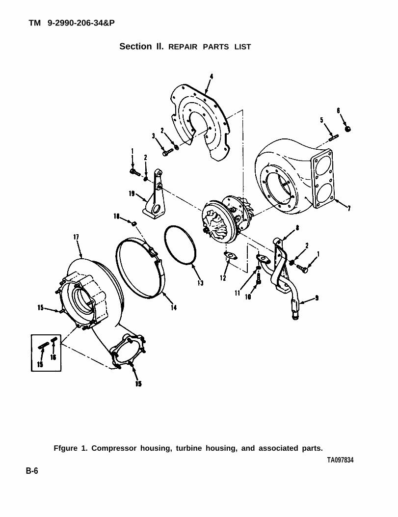
Section Il. REPAIR PARTS LIST
Ffgure 1. Compressor housing, turbine housing, and associated parts.
TA097834B-6
TM 9-2990-206-34&P

TM9-2990-206-34&P(1) (2) (3) (4) (5) (6) (7) (8)ILLUSTRATION
QTY(a) (b) NATIONAL INCFIG. ITEM SMR STOCK PART INNO. NO. CODE NUMBER NUMBER FSCM DESCRIPTION U/M UNIT
GROUP 0305TURBOSUPERCHARGER, AIRSEARCH MODELT18CO1, PART NUMBER 11669107-1
1 1 PAHZZ 5306-01-061-1409 S9418822 08179 BOLT, MACHINE: MOUNTING LEGS TOCENTER HOUSING ASSEMBLY EA 4
1 2 PAHZZ 5310-01-060-7264 400140-400 08179 WASHER, LOCK: MOUNTING LEGS TOCENTER HOUSING ASSEMBLY (4),TURBOSUPERCHARGER SHIELD ANDHOUSING ASSEMBLY TO TURBINEHOUSING (8) EA 12
1 3 PAHZZ 5306-01-061-1408 400132-403 08179 BOLT, MACHINE: TURBOSUPERCHARGERSHIELD AND CENTER HOUSING ASSEMBLYTO TURBINE HOUSING EA 8
1 4 PAHZZ 2950-01-060-8522 409356 08179 SHIELD, TURBOSUPERCHARGER: HEAT EA 1(NOT USED ON ENGINE MODELAVDS-1790-2DR
1 5 PAHZZ 5307-01-059-0120 400602-1 08179 STUD, PLAIN: STANDARD TURBINEHOUSING TO EXHAUST PIPE EA 6
1 6 PAOZZ 5310-01-151-2732 SPL51712-6 15653 NUT, SELF-LOCKING, HEXAGON: TURBINEHOUSING TO EXHAUST PIPE EA 6
1 7 XAHZZ 409394-11 08197 HOUSING, TURBINE EA 1
1 8 XAHZZ 409343 08179 LEG, MOUNTING: RIGHT SIDE EA 1
1 9 PAFZZ 4710-01-061-0911 409349 08179 TUBE ASSEMBLY, METAL: OIL DRAIN EA 1
1 10 PAFZZ 5306-01-061-1410 S9418823 08179 BOLT, MACHINE: OIL DRAIN TUBEASSEMBLY TO CENTER HOUSINGASSEMBLY EA 2
1 11 PAFZZ 5310-01-060-7264 400140-400 08179 WASHER,LOCK: OIL DRAIN TUBE TOCENTER HOUSING ASSEMBLY EA 2
1 12 PAFZZ 5330-01-060-6889 409267-2 08179 GASKET: OIL DRAIN TUBE ASSEMBLY,OF KIT PART NO. 409448 EA 1
1 13 KFHZZ 403069-28 08179 PACKING, PREFORMED: COMPRESSORHOUSING TO BACK PLATE ASSEMBLY,PART OF KIT PART NO. 409448 EA 1
1 14 PFHZZ 5340-01-060-8007 400500-925 08179 COUPLING, CLAMP, GROOVED: COMPRESSORHOUSING TO BACK PLATE ASSEMBLY EA 1
1 15 PAHZZ 5307-01-059-0119 400678 08179 STUD, PLAIN: COMPRESSOR HOUSING TOENGINE AIR INTAKE TUBE (6),COMPRESSOR HOUSING TO VEHICLE AIRINTAKE TUBE (8) EA 14
1 16 PAHZZ 5340-00-290-4520 MS21208C5-20 96906 INSERT, SCREW THREAD: COMPRESSORHOUSING STUDS (REPAIR ONLY) EA V
1 17 XAHZZ 409373-1 08179 HOUSING, COMPRESSOR EA 1
1 18 PAHZZ 5310-00-298-2747 MS20500-428 96906 NUT, SELF-LOCKING, HEXAGON: GROOVEDCLAMP COUPLING EA 1
1 19 XAHZZ 409347 08179 LEG, MOUNTING: LEFT SIDE EA 1
CHANGE 1 B-7
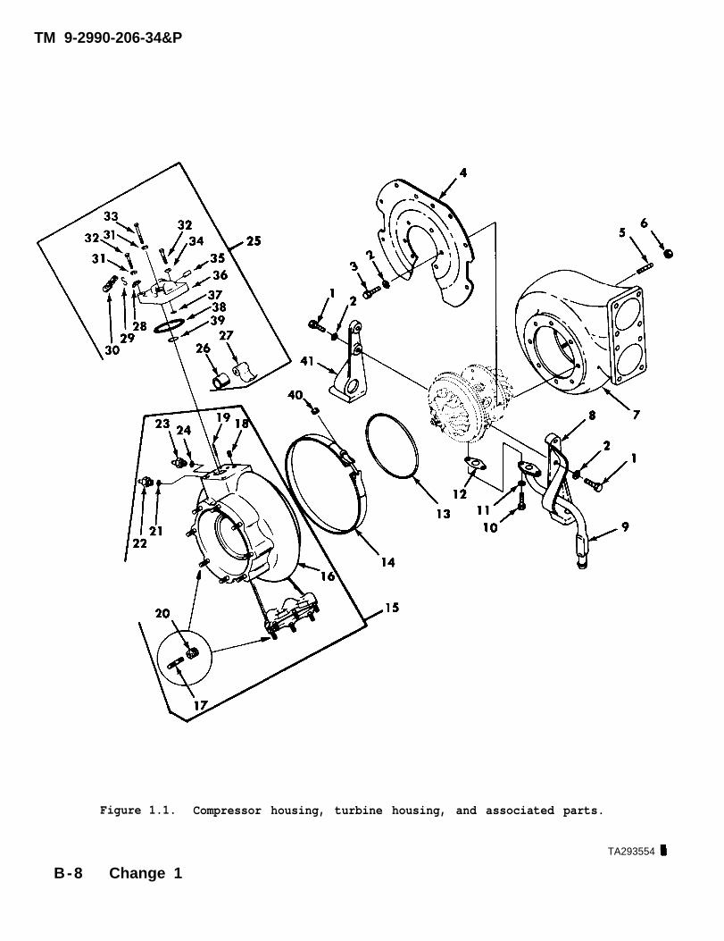
Figure 1.1. Compressor housing, turbine housing, and associated parts.
TA293554
B-8 Change 1
TM 9-2990-206-34&P
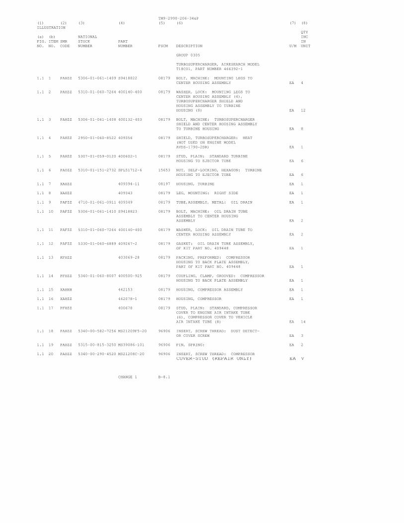
TM9-2990-206-34&P(1) (2) (3) (4) (5) (6) (7) (8)ILLUSTRATION
QTY(a) (b) NATIONAL INCFIG. ITEM SMR STOCK PART INNO. NO. CODE NUMBER NUMBER FSCM DESCRIPTION U/M UNIT
GROUP 0305
TURBOSUPERCHARGER, AIRESEARCH MODELT18C01, PART NUMBER 466392-1
1.1 1 PAHZZ 5306-01-061-1409 S9418822 08179 BOLT, MACHINE: MOUNTING LEGS TOCENTER HOUSING ASSEMBLY EA 4
1.1 2 PAHZZ 5310-01-060-7264 400140-400 08179 WASHER, LOCK: MOUNTING LEGS TOCENTER HOUSING ASSEMBLY (4),TURBOSUPERCHARGER SHIELD ANDHOUSING ASSEMBLY TO TURBINEHOUSING (8) EA 12
1.1 3 PAHZZ 5306-01-061-1408 400132-403 08179 BOLT, MACHINE: TURBOSUPERCHARGERSHIELD AND CENTER HOUSING ASSEMBLYTO TURBINE HOUSING EA 8
1.1 4 PAHZZ 2950-01-060-8522 409356 08179 SHIELD, TURBOSUPERCHARGER: HEAT(NOT USED ON ENGINE MODELAVDS-1790-2DR) EA 1
1.1 5 PAHZZ 5307-01-059-0120 400602-1 08179 STUD, PLAIN: STANDARD TURBINEHOUSING TO EJECTOR TUBE EA 6
1.1 6 PAOZZ 5310-01-151-2732 SPL51712-6 15653 NUT, SELF-LOCKING, HEXAGON: TURBINEHOUSING TO EJECTOR TUBE EA 6
1.1 7 XAHZZ 409394-11 08197 HOUSING, TURBINE EA 1
1.1 8 XAHZZ 409343 08179 LEG, MOUNTING: RIGHT SIDE EA 1
1.1 9 PAFZZ 4710-01-061-0911 409349 08179 TUBE,ASSEMBLY, METAL: OIL DRAIN EA 1
1.1 10 PAFZZ 5306-01-061-1410 S9418823 08179 BOLT, MACHINE: OIL DRAIN TUBEASSEMBLY TO CENTER HOUSINGASSEMBLY EA 2
1.1 11 PAFZZ 5310-01-060-7264 400140-400 08179 WASHER, LOCK: OIL DRAIN TUBE TOCENTER HOUSING ASSEMBLY EA 2
1.1 12 PAFZZ 5330-01-060-6889 409267-2 08179 GASKET: OIL DRAIN TUBE ASSEMBLY,OF KIT PART NO. 409448 EA 1
1.1 13 KFHZZ 403069-28 08179 PACKING, PREFORMED: COMPRESSORHOUSING TO BACK PLATE ASSEMBLY,PART OF KIT PART NO. 409448 EA 1
1.1 14 PFHZZ 5340-01-060-8007 400500-925 08179 COUPLING, CLAMP, GROOVED: COMPRESSORHOUSING TO BACK PLATE ASSEMBLY EA 1
1.1 15 XAHHH 442153 08179 HOUSING, COMPRESSOR ASSEMBLY EA 1
1.1 16 XAHZZ 442078-1 08179 HOUSING, COMPRESSOR EA 1
1.1 17 PFHZZ 400678 08179 STUD, PLAIN: STANDARD, COMPRESSORCOVER TO ENGINE AIR INTAKE TUBE(6), COMPRESSOR COVER TO VEHICLEAIR INTAKE TUBE (8) EA 14
1.1 18 PAHZZ 5340-00-582-7256 MS21209F5-20 96906 INSERT, SCREW THREAD: DUST DETECT-OR COVER SCREW EA 3
1.1 19 PAHZZ 5315-00-815-3250 MS39086-101 96906 PIN, SPRING: EA 2
1.1 20 PAHZZ 5340-00-290-4520 MS21208C-20 96906 INSERT, SCREW THREAD: COMPRESSORCOVER-STUD (REPAIR ONLY) EA V
CHANGE 1 B-8.1
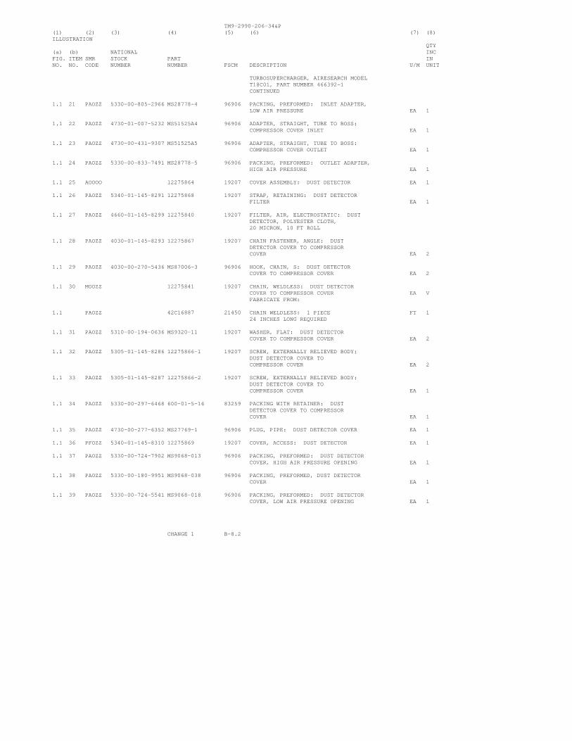
TM9-2990-206-34&P(1) (2) (3) (4) (5) (6) (7) (8)ILLUSTRATION
QTY(a) (b) NATIONAL INCFIG. ITEM SMR STOCK PART INNO. NO. CODE NUMBER NUMBER FSCM DESCRIPTION U/M UNIT
TURBOSUPERCHARGER, AIRESEARCH MODELT18C01, PART NUMBER 466392-1CONTINUED
1.1 21 PAOZZ 5330-00-805-2966 MS28778-4 96906 PACKING, PREFORMED: INLET ADAPTER,LOW AIR PRESSURE EA 1
1.1 22 PAOZZ 4730-01-007-5232 MS51525A4 96906 ADAPTER, STRAIGHT, TUBE TO BOSS:COMPRESSOR COVER INLET EA 1
1.1 23 PAOZZ 4730-00-431-9307 MS51525A5 96906 ADAPTER, STRAIGHT, TUBE TO BOSS:COMPRESSOR COVER OUTLET EA 1
1.1 24 PAOZZ 5330-00-833-7491 MS28778-5 96906 PACKING, PREFORMED: OUTLET ADAPTER,HIGH AIR PRESSURE EA 1
1.1 25 AOOOO 12275864 19207 COVER ASSEMBLY: DUST DETECTOR EA 1
1.1 26 PAOZZ 5340-01-145-8291 12275868 19207 STRAP, RETAINING: DUST DETECTORFILTER EA 1
1.1 27 PAOZZ 4660-01-145-8299 12275840 19207 FILTER, AIR, ELECTROSTATIC: DUSTDETECTOR, POLYESTER CLOTH,20 MICRON, 10 FT ROLL
1.1 28 PAOZZ 4030-01-145-8293 12275867 19207 CHAIN FASTENER, ANGLE: DUSTDETECTOR COVER TO COMPRESSORCOVER EA 2
1.1 29 PAOZZ 4030-00-270-5436 MS87006-3 96906 HOOK, CHAIN, S: DUST DETECTORCOVER TO COMPRESSOR COVER EA 2
1.1 30 MOOZZ 12275841 19207 CHAIN, WELDLESS: DUST DETECTORCOVER TO COMPRESSOR COVER EA VFABRICATE FROM:
1.1 PAOZZ 42C16887 21450 CHAIN WELDLESS: 1 PIECE FT 124 INCHES LONG REQUIRED
1.1 31 PAOZZ 5310-00-194-0636 MS9320-11 19207 WASHER, FLAT: DUST DETECTORCOVER TO COMPRESSOR COVER EA 2
1.1 32 PAOZZ 5305-01-145-8286 12275866-1 19207 SCREW, EXTERNALLY RELIEVED BODY:DUST DETECTOR COVER TOCOMPRESSOR COVER EA 2
1.1 33 PAOZZ 5305-01-145-8287 12275866-2 19207 SCREW, EXTERNALLY RELIEVED BODY:DUST DETECTOR COVER TOCOMPRESSOR COVER EA 1
1.1 34 PAOZZ 5330-00-297-6468 600-01-5-16 83259 PACKING WITH RETAINER: DUSTDETECTOR COVER TO COMPRESSORCOVER EA 1
1.1 35 PAOZZ 4730-00-277-6352 MS27769-1 96906 PLUG, PIPE: DUST DETECTOR COVER EA 1
1.1 36 PFOZZ 5340-01-145-8310 12275869 19207 COVER, ACCESS: DUST DETECTOR EA 1
1.1 37 PAOZZ 5330-00-724-7902 MS9068-013 96906 PACKING, PREFORMED: DUST DETECTORCOVER, HIGH AIR PRESSURE OPENING EA 1
1.1 38 PAOZZ 5330-00-180-9951 MS9068-038 96906 PACKING, PREFORMED, DUST DETECTORCOVER EA 1
1.1 39 PAOZZ 5330-00-724-5541 MS9068-018 96906 PACKING, PREFORMED: DUST DETECTORCOVER, LOW AIR PRESSURE OPENING EA 1
CHANGE 1 B-8.2

TM9-2990-206-34&P(1) (2) (3) (4) (5) (6) (7) (8)ILLUSTRATION
QTY(a) (b) NATIONAL INCFIG. ITEM SMR STOCK PART INNO. NO. CODE NUMBER NUMBER FSCM DESCRIPTION U/M UNIT
GROUP 0305
TURBOSUPERCHARGER, AIRESEARCH MODELT18C01, PART NUMBER 466392-1-CONTINUED
1.1 40 PAHZZ 5310-00-298-2747 MS20500-428 96906 NUT, SELF-LOCKING, HEXAGON: GROOVEDCLAMP COUPLING EA 1
1.1 41 XAHZZ 409347 08179 LEG, MOUNTING: LEFT SIDE EA 1
CHANGE 1 B-8.3

TM 9-2990-206-34&P
Figure 2. Center housing assembly and associated parts.
(1) (2)lLLUSTRATION
( 4 )
(a) (b)
FIG. ITEM SMRNO. NO. CODE
(3)
N A T I O N A LS T O C K
N U M B E R
(5)
FSCM
( 6 ) (7) (8)
Q T Y I N C I N
DESCRIPTION U / M UNIT
P A R T
N U M B E R
2
2
2
2
1
2
3
4
PAHZZ
PAHZZ
PAHZZ
XAHZZ
5306-01-061-1409
5310-01-060-9103
2815-01-072-9926
S 9 4 1 8 8 2 2
4 0 0 6 5 0 - 2
4 0 8 8 6 3 - 4
4 0 8 1 5 5
0 8 1 7 9
0 8 1 7 9
0 8 1 7 9
0 8 1 7 9
GROUP 0305 - CONTINUED
BOLT, MACHINE: BACK PLATE ASSEMBLY TO CENTER HOUSING ASSEMBLY
WASHER, FLAT: BACK PLATE ASSEMBLY TO CENTER HOUSING ASSEMBLY
BACK PLATE, SUPERCHARGER
PLATE, IDENTIFICATION: TURBOSUPER- CHARGER
E A
E A
E A
E A
4
4
1
1
B - 8 . 4 Change 1 T A 2 9 3 5 5 5

TM9-2990-206-34&P(1) (2) (3) (4) (5) (6) (7) (8)ILLUSTRATION
QTY(a) (b) NATIONAL INCFIG. ITEM SMR STOCK PART INNO. NO. CODE NUMBER NUMBER FSCM DESCRIPTION U/M UNIT
GROUP 03050 - CONTINUED
2 5 XAHZZ S173639 08179 SCREW: IDENTIFICATION PLATE EA 2
2 6 XAHZZ 407214-7 08179 HOUSING ASSEMBLY, CENTER EA 1
2 7 KFHZZ 400408 08179 RING, RETAINING: THRUST BEARINGWASHER AND SLEEVE BEARING, PART OFKIT PART NO. 409448 EA 3
2 8 KFHZZ 408306 08179 BEARING, SLEEVE: TURBINE WHEEL EA 2ASSEMBLY, PART OF KIT PART NO.409448
2 9 KFHZZ 407135 08179 WASHER, BEARING, THRUST: TURBINEWHEEL ASSEMBLY, PART OF KIT PARTNO. 409448 EA 2
2 10 XAHZZ 407737 08179 WHEEL, SHROUD EA 1
2 11 PFHZZ 2950-01-059-4219 409352-1 08179 TURBINE WHEEL ASSEMBLY EA 1
2 12 PAHZZ 2950-00-276-7491 403818-31 70210 SEAL RING , METAL: TURBINE WHEELASSEMBLY, PART OF KIT PART NO.409448 EA 1
2 13 KFHZZ 408844 08179 BEARING, THRUST: TURBINE WHEEL ASSEM-BLY, PART OF KIT PART NO. 409448 EA 1
2 14 PFHZZ 2950-00-983-7294 406499-2 08179 RING, THRUST, TURBOCHARGER: TURBINEWHEEL ASSEMBLY EA 1
2 15 PFHZZ 5365-01-118-8822 408768-1 08179 SPACER, SLEEVE: TURBINE WHEELASSEMBLY EA 1
2 16 PAHZZ 2950-00-821-2077 403818 70210 RING, TURBOCHARGER: THRUST SPACERPART OF KIT PART NO. 409448 EA 2
2 17 KFHZZ 400424-6 08179 SEAL, RING, CENTER HOUSING ASSEMBLY,PART OF KIT PART NO. 409448 EA 1
2 18 PAHZZ 5310-00-070-6870 400379 08179 NUT, SELF-LOCKING, EXTENDED WASHER,DOUBLE HEXAGON: TURBOSUPERCHARGERIMPELLER EA 1
2 19 PAHZZ 2950-01-060-0962 409269-2 08179 IMPELLER, TURBOSUPERCHARGER EA 1
2 PAHZZ 2950-01-058-9999 409448 08179 PARTS KIT, TURBOCHARGER EA 1
COMPOSED OF:
1 12 GASKET EA 1
1 13 PACKING, PREFORMED EA 1
2 7 RING, RETAINING EA 3
2 8 BEARING, SLEEVE EA 2
2 9 WASHER, BEARING, THRUST EA 2
2 12 SEAL, RING, METAL EA 1
2 13 BEARING, THRUST EA 1
2 16 RING, TURBOCHARGER EA 2
2 17 SEAL, RING EA 1
CHANGE 1 B-9
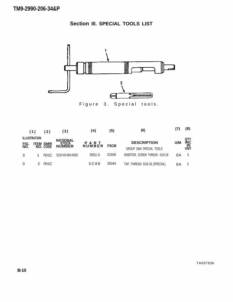
F i g u r e 3 . S p e c i a l t o o l s .
TM9-2990-206-34&P
Section Ill. SPECIAL TOOLS LIST
(5) (7) (8)( 1 ) (6)( 2 ) ( 3 ) (4)
ILLUSTRATION
FIG. ITEMNO. NO.
3 1
3 2
SMRCODE
PEHZZ
PEHZZ
NATIONALSTOCK
NUMBER
5120-00-804-6055
P A R TN U M B E R
3551-5
5 C 8 8
FSCM
01556
26344
DESCRIPTION
GROUP 2604 SPECIAL TOOLS
INSERTER, SCREW THREAD : 5/16-18
TAP, THREAD: 5/16-18 (SPECIAL)
U/M
EA
EA
QTYINC INUNIT
1
1
TA097836
B-10
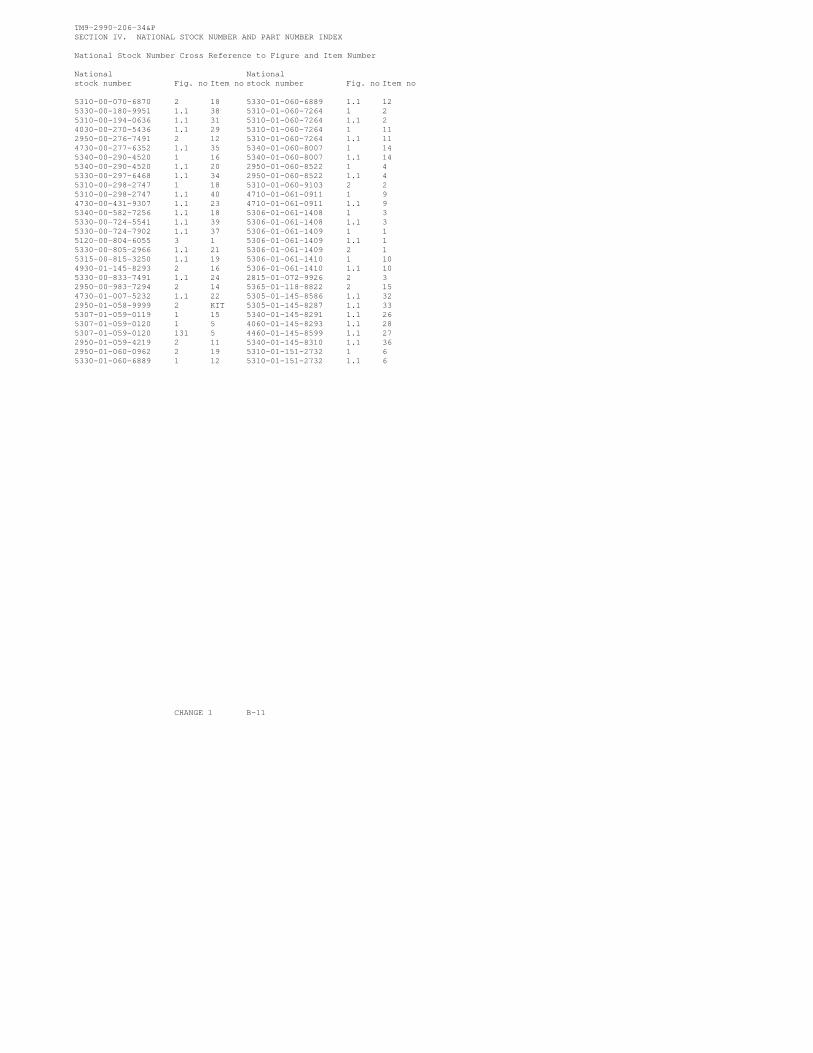
TM9-2990-206-34&PSECTION IV. NATIONAL STOCK NUMBER AND PART NUMBER INDEX
National Stock Number Cross Reference to Figure and Item Number
National Nationalstock number Fig. no Item no stock number Fig. no Item no
5310-00-070-6870 2 18 5330-01-060-6889 1.1 125330-00-180-9951 1.1 38 5310-01-060-7264 1 25310-00-194-0636 1.1 31 5310-01-060-7264 1.1 24030-00-270-5436 1.1 29 5310-01-060-7264 1 112950-00-276-7491 2 12 5310-01-060-7264 1.1 114730-00-277-6352 1.1 35 5340-01-060-8007 1 145340-00-290-4520 1 16 5340-01-060-8007 1.1 145340-00-290-4520 1.1 20 2950-01-060-8522 1 45330-00-297-6468 1.1 34 2950-01-060-8522 1.1 45310-00-298-2747 1 18 5310-01-060-9103 2 25310-00-298-2747 1.1 40 4710-01-061-0911 1 94730-00-431-9307 1.1 23 4710-01-061-0911 1.1 95340-00-582-7256 1.1 18 5306-01-061-1408 1 35330-00-724-5541 1.1 39 5306-01-061-1408 1.1 35330-00-724-7902 1.1 37 5306-01-061-1409 1 15120-00-804-6055 3 1 5306-01-061-1409 1.1 15330-00-805-2966 1.1 21 5306-01-061-1409 2 15315-00-815-3250 1.1 19 5306-01-061-1410 1 104930-01-145-8293 2 16 5306-01-061-1410 1.1 105330-00-833-7491 1.1 24 2815-01-072-9926 2 32950-00-983-7294 2 14 5365-01-118-8822 2 154730-01-007-5232 1.1 22 5305-01-145-8586 1.1 322950-01-058-9999 2 KIT 5305-01-145-8287 1.1 335307-01-059-0119 1 15 5340-01-145-8291 1.1 265307-01-059-0120 1 5 4060-01-145-8293 1.1 285307-01-059-0120 131 5 4460-01-145-8599 1.1 272950-01-059-4219 2 11 5340-01-145-8310 1.1 362950-01-060-0962 2 19 5310-01-151-2732 1 65330-01-060-6889 1 12 5310-01-151-2732 1.1 6
CHANGE 1 B-11

TM9-2990-206-34&P
Part Number Cross Reference to Figure and Item NumberItem Fig. Item
Part number FSCM No. Part number FSCM No. No.
MS20500-428 96906 1 18 400500-925 08179 1 14MS20500-428 96906 1.1 40 400500-925 08179 1.1 14MS21208C5-20 96906 1 16 400602-1 08179 1 5MS21208C5-20 96906 1.1 20 400602-1 08179 1.1 5MS21209F5-20 96906 1.1 18 400650-2 08179 2 2MS27769-1 96906 1.1 35 400678 08179 1 15MS28778-4 96906 1.1 21 400678 08179 1.1 17MS28778-5 96906 1.1 24 403069-28 08179 1 13MS39086-101 96906 1.1 19 403069-28 08179 1.1 13MS50525A4 96906 1.1 22 403818 70210 2 16MS51525A5 96906 1.1 23 403818-31 70210 2 12MS87006-3 96906 1.1 28 406499-2 08179 2 14MS9068-013 96906 1.1 37 407135 08179 2 9MS9068-018 96906 1.1 39 407214-7 08179 2 6MS9068-038 96906 1.1 38 407737 08179 2 10MS9320-11 19207 1.1 30 408155 08179 2 4S173639 08179 2 5 408306 08179 2 8S9418822 08179 1 1 408768-1 08179 2 15S9418822 08179 1.1 1 408844 08179 2 13S9418822 08179 2 1 408863-4 08179 2 3S9418823 08179 1 10 409267-2 08179 1 12S9418823 08179 1.1 10 409267-2 08179 1.1 12SPL51712-6 15653 1 6 409269-2 08179 2 19SPL51712-6 15653 1.1 6 409343 08179 1 812275840 19207 1.1 26 409343 08179 1.1 812275841 19207 1.1 29 409347 08179 1 1912275864 19207 1.1 34 409347 08179 1.1 4112275866-1 19207 1.1 31 409349 08179 1 912275866-2 19207 1.1 32 409349 08179 1.1 912275867 19207 1.1 27 49352-1 08179 2 1112275868 19207 1.1 25 409356 08179 1 412275869 19207 1.1 36 409356 08179 1.1 43551-5 01556 3 1 409373-1 08179 1 17400132-403 08179 1 3 409397-11 08179 1 7400132-403 08179 1.1 3 409394-11 08179 1.1 7400140-400 08179 1 2 409448 08179 2 KIT400140-400 08179 1.1 2 42C16887 21450 1.1400140-400 08179 1 11 442078-1 08179 1.1 16400140-400 08179 1.1 11 442153 08179 1.1 15400379 08179 2 18 5CBB 26344 3 2400408 08179 2 7 600-01-5-16 83259 1.1 34400424-6 08179 2 17
B-12 CHANGE 1

APPENDIX C
EXPENDABLE SUPPLIES AND MATERIALS LIST
This append ix l i s ts expendab le sup- r e p a i r t h e A i R e s e a r c h M o d e l T 1 8 C O 1p l i e s a n d m a t e r i a l y o u w i l l n e e d t o t u r b o s u p e r c h a r g e r .
Unito f
I t e m NSN Description measure
1. 7920-00-205-1711 RAG, WIPING, COTTON, WHITE:50 lb bale, DDD-R-30 (81348)
2. 9150-00-231-6689 PL SPECIAL LUBE OIL: 1 qtcan, VV-L-800 (81348)
3. 6850-00-281-1985 SD DRYCLEANING SOLVENT: 1 gal -lon can, P-D-WI, Type II
4. 9150-00-948-6912 SOLID FILM LUBRICANT, HEAT-CURED, CORROSION INHIBITING:MIL-L-46010
9150-00-948-7025 SOLID FILM LUBRICANT, HEAT-CURED, CORROSION INHIBITING:MIL-L-46010
l b
q t
gal
qt
gal
TM 9-2990-206-34&P
C - 1 / C - 2
BLANK

TM 9-2990-206-34&P
ALPHABETICAL INDEX
Subject, Page Number
A
Alphabetical Index, IndexAppendix A, A-1Appendix B, B-1Appendix C, C-1
B
BackplateInspection, 3-12Installation, 3-22Removal, 3-7Repair, 3-16
C
Center Housing AssemblyInspection, 3-14Installation, 3-24, 3-25Removal, 3-4Repair, 3-17
ChainInstallation, 3-30Removal, 3-10
Chain FastenerInstallation, 3-30Removal, 3-10
Chain “S” HookInstallation, 3-30Removal, 3-10
Clamp (See Grooved Clamp Coupling)Cleaning, 3-10Common Tools, 3-1Cammon Tools and Equipment, 2-5Compressor Housing
Inspection, 3-10Installation, 3-25Removal, 3-3Repair, 3-16
Compressor Wheel (See TurbosuperchargerImpeller)
Compressor Wheel Nut (See Impeller Nut)
D
Description of Turbosupercharger, 1-2Dust Detector Cover
Inspection, 3-16Installation, 3-30Removal, 3-10
E
End Play, 2-4Expendable Materials, 3-1Expendable Supplies and Materials List,
F
FilterInstallation, 3-29Removal, 3-10.1
Filter Retaining StrapInstallation, 3-29Removal, 3-10.1
G
Grooved Clamp CouplingInspection,InstallationRemoval, 3-3Repair, 3-17
H
Heat Shield (See TurbosuperchargerShield)
Holding Fixture, 2-5, 3-5, 3-23How to Locate Parts, B-4How to Use This Manual, iii
Change 1 Index 1
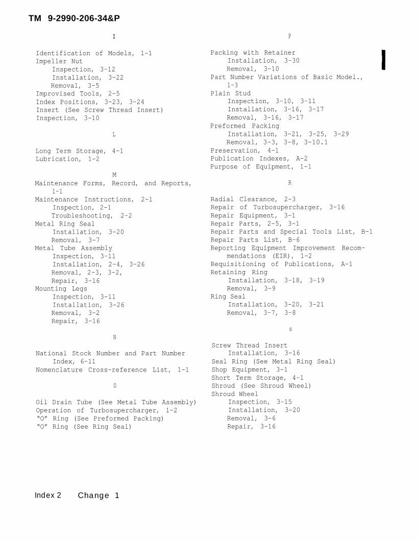
I
Identification of Models, 1-1Impeller Nut
Inspection, 3-12Installation, 3-22Removal, 3-5
Improvised Tools, 2-5Index Positions, 3-23, 3-24Insert (See Screw Thread Insert)Inspection, 3-10
L
Long Term Storage, 4-1Lubrication, 1-2
MMaintenance Forms, Record, and Reports,
1-1Maintenance Instructions, 2-1
Inspection, 2-1Troubleshooting, 2-2
Metal Ring SealInstallation, 3-20Removal, 3-7
Metal Tube AssemblyInspection, 3-11Installation, 2-4, 3-26Removal, 2-3, 3-2,Repair, 3-16
Mounting LegsInspection, 3-11Installation, 3-26Removal, 3-2Repair, 3-16
P
Packing with RetainerInstallation, 3-30Removal, 3-10
Part Number Variations of Basic Model.,1-3
Plain StudInspection, 3-10, 3-11Installation, 3-16, 3-17Removal, 3-16, 3-17
Preformed PackingInstallation, 3-21, 3-25, 3-29Removal, 3-3, 3-8, 3-10.1
Preservation, 4-1Publication Indexes, A-2Purpose of Equipment, 1-1
R
Radial Clearance, 2-3Repair of Turbosupercharger, 3-16Repair Equipment, 3-1Repair Parts, 2-5, 3-1Repair Parts and Special Tools List, B-1Repair Parts List, B-6Reporting Equipment Improvement Recom-
mendations (EIR), 1-2Requisitioning of Publications, A-1Retaining Ring
Installation, 3-18, 3-19Removal, 3-9
Ring SealInstallation, 3-20, 3-21Removal, 3-7, 3-8
sN
National Stock Number and Part NumberIndex, 6-11
Nomenclature Cross-reference List, 1-1
0
Oil Drain Tube (See Metal Tube Assembly)Operation of Turbosupercharger, 1-2“O” Ring (See Preformed Packing)“O” Ring (See Ring Seal)
Screw Thread InsertInstallation, 3-16
Seal Ring (See Metal Ring Seal)Shop Equipment, 3-1Short Term Storage, 4-1Shroud (See Shroud Wheel)Shroud Wheel
Inspection, 3-15Installation, 3-20Removal, 3-6Repair, 3-16
Index 2 Change 1
TM 9-2990-206-34&P
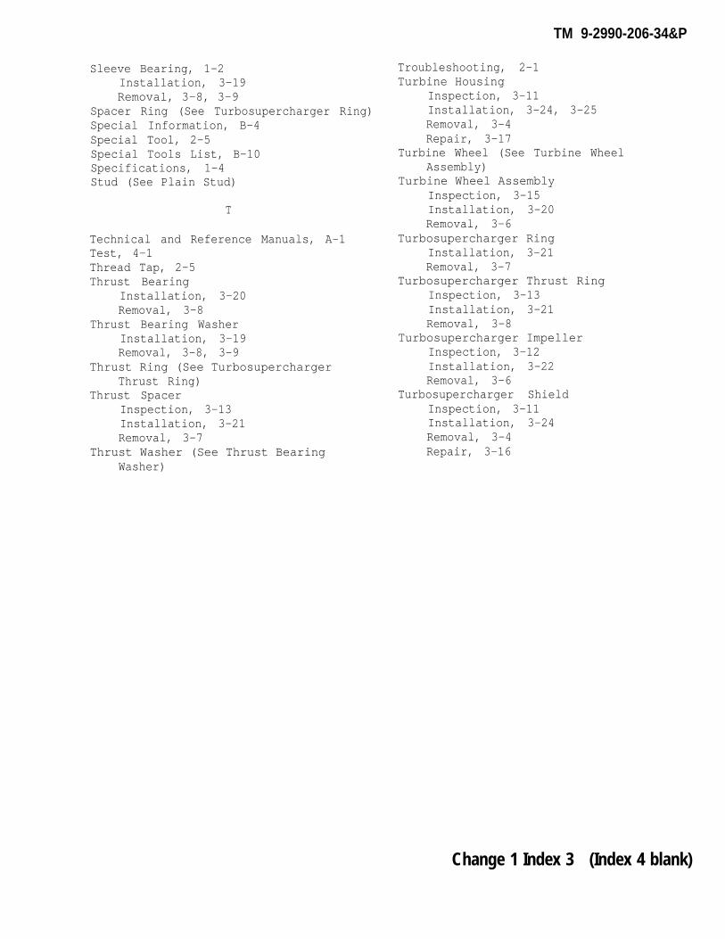
Sleeve Bearing, 1-2Installation, 3-19Removal, 3-8, 3-9
Spacer Ring (See Turbosupercharger Ring)Special Information, B-4Special Tool, 2-5Special Tools List, B-10Specifications, 1-4Stud (See Plain Stud)
T
Technical and Reference Manuals, A-1Test, 4-1Thread Tap, 2-5Thrust Bearing
Installation, 3-20Removal, 3-8
Thrust Bearing WasherInstallation, 3-19Removal, 3-8, 3-9
Thrust Ring (See TurbosuperchargerThrust Ring)
Thrust SpacerInspection, 3-13Installation, 3-21Removal, 3-7
Thrust Washer (See Thrust BearingWasher)
Troubleshooting, 2-1Turbine Housing
Inspection, 3-11Installation, 3-24, 3-25Removal, 3-4Repair, 3-17
Turbine Wheel (See Turbine WheelAssembly)
Turbine Wheel AssemblyInspection, 3-15Installation, 3-20Removal, 3-6
Turbosupercharger RingInstallation, 3-21Removal, 3-7
Turbosupercharger Thrust RingInspection, 3-13Installation, 3-21Removal, 3-8
Turbosupercharger ImpellerInspection, 3-12Installation, 3-22Removal, 3-6
Turbosupercharger ShieldInspection, 3-11Installation, 3-24Removal, 3-4Repair, 3-16
Change 1 Index 3 (Index 4 blank)
TM 9-2990-206-34&P

BY Order of the Secretary of the Army:
TM 9-2990-206-34&P
E.C. MEYERGeneral, United States Army
Chief of Staff
Official:
J.C. PENNINGTONMajor General. United States Army
The Adjutant General
DISTRIBUTION:
To be distributed in accordance with DA Form 12-37, Direct and General SupportMaintenance requirements for Medium, M88A1; Tank, Combat, Full Tracked; 105MMGun, M60A1 (RISE); Tank, Combat Full Tracked: 105MM Gun, M48A5, and M6OA3Tank Turret.
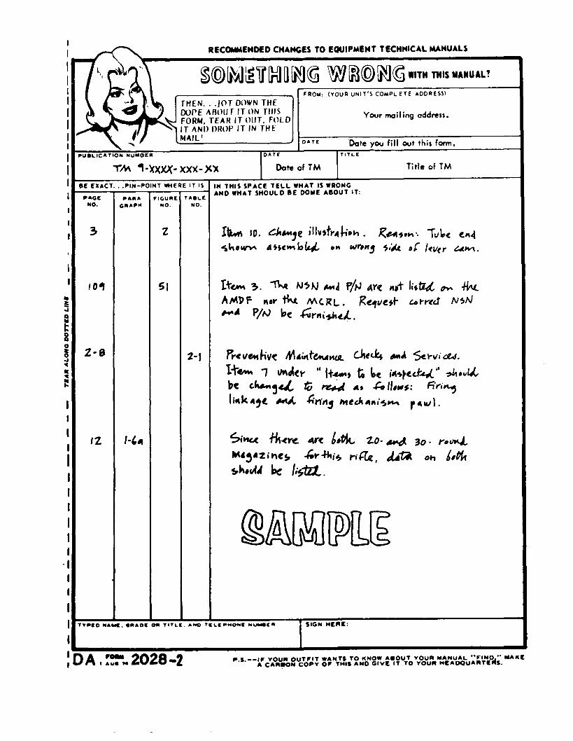
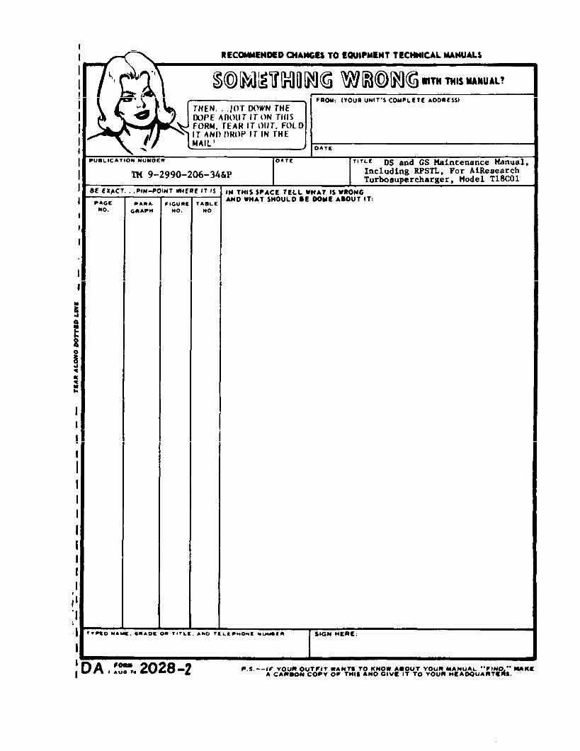

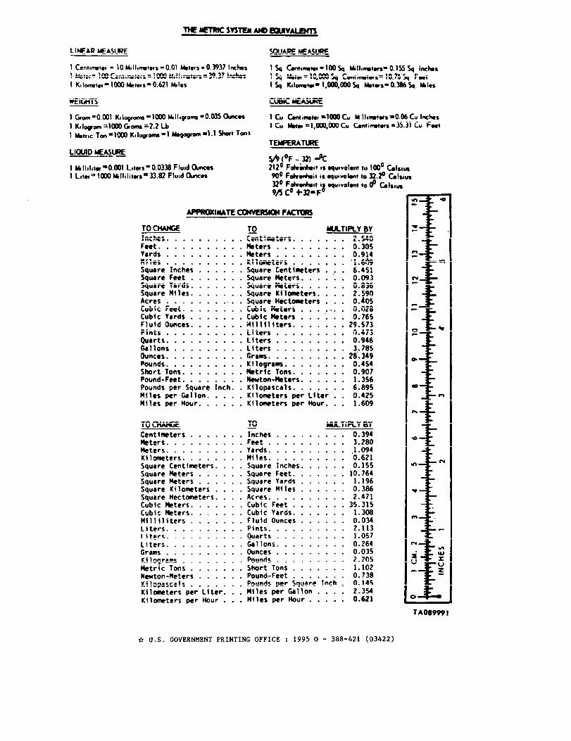


This fine document...
Was brought to you by me:
Liberated Manuals -- free army and government manuals
Why do I do it? I am tired of sleazy CD-ROM sellers, who take publicly available information, slap “watermarks” and other junk on it, and sell it. Those masters of search engine manipulation make sure that their sites that sell free information, come up first in search engines. They did not create it... They did not even scan it... Why should they get your money? Why are not letting you give those free manuals to your friends?
I am setting this document FREE. This document was made by the US Government and is NOT protected by Copyright. Feel free to share, republish, sell and so on.
I am not asking you for donations, fees or handouts. If you can, please provide a link to liberatedmanuals.com, so that free manuals come up first in search engines:
<A HREF=http://www.liberatedmanuals.com/>Free Military and Government Manuals</A>
– SincerelyIgor Chudovhttp://igor.chudov.com/
– Chicago Machinery Movers