tm1-405_1941
DESCRIPTION
Aircraft Engines 1941TRANSCRIPT

us no. 1-40S c.j
TM1-405
'■ril'»' T.IU5
WAR DEPARTMENT
TECHNICAL MANUAL
AIRCRAFT ENGINES December 9,1941
LIÜÜARY MICH.
DISTRIBUTION STATEMENT A Approved for Public Release
Distribution Unlimited
Reproduced From Best Available Copy
20000518 139

us /' p i-tfte' *TM 1-405
d , ?/ x
TECHNICAL MANUAL"! WAR DEPARTMENT, No. 1-405 J WASHINGTON, December 9, 1941.
AIRCRAFT ENGINES
Prepared under direction of the Chief of the Air Corps
Paragraphs
SECTION I. Internal-combustion engine principles 1-8 II. Classification and description of engine types 9-17
III. Description and construction of engine units 18-34 IV. Repair principles 35-44 V. Engine lubrication 45-47
VI. Engine cooling : 48-52
SECTION I
INTERNAL-COMBUSTION ENGINE PRINCIPLES
Paragraph
General 1 Conversion of heat into mechanical energy 2 Engine cycles 3 Four-stroke cycle principle _ 4 Two-stroke cycle principle 5 Diesel principle 6 Compressing the charge 1 Horsepower calculations 8
1. General.—a. Rapid progress has been made in the past few years in the development of high-powered aircraft engines; however, insofar as fundamentals are concerned, they have not changed since their conception at the beginning of the twentieth century.
b. The power developed by internal-combustion engines is depend- ent upon the type of fuel used; therefore it necessarily follows that the future increases in power obtained from conventional aircraft en- gines depend upon the development of fuels. However, metallurgy will also take an important part in future development, in that the metals used in an engine of the future must withstand increased stresses.
"This manual supersedes TM 1-405, November 4, 1940.
424577°—42 1 \

TM 1-405 2-3 AIR CORPS
2. Conversion of heat into mechanical energy.-^-Iriternal-^ combustion engines are of a class of prime movers known as "heat en- gines," that is, they convert heat energy into useful mechanical energy through a process of combustion (fig. 1). A mixture of fuel and air in proper proportion, after it has been compressed to a comparatively high pressure, is burned within the cylinder. The sudden increase 'in pressure, due to combustion, causes the piston to move against the load and deliver mechanical energy to the engine crankshaft. The fuel must be vaporized, or in a gaseous state, when used in an internal-1
1. Crankshaft. 4. Fuel and air mixture before compression. 2. Cylinder. 5. Fuel and air mixture compressed. 3. Piston. 6. Igniter or spark plug.
FIGURE 1.—Method of converting heat energy to mechanical energy in an internal- combustion engine. . \
combustion engine and must be mixed with the proper proportion of ■ air in order to burn properly. The igniting ©f the gas is of the ut1
most importance. The various methods of obtaining and timing thfe' ignition spark and the proper regulation and adjustment of the differ-' ent parts of the power plant are vital elements in the operation of a conventional aircraft engine. ^ ' , ■<■'
3. Engine cycles.^«. In order to operate continuously arid de-!
liver power, the engine must go through a routine of operations, each act being performed over and Over in the same sequence.' 'Eafch'^ these operations is known as an event, and a series of events is known'

TM 1-405 AIRCRAFT ENGINES 3-4
as a cycle, or as a cycle of events. In a gasoline engine, the following events must take place:
(1) Admitting or forcing a charge into the cylinder. (2) Compressing the charge. (3) Igniting the charge. (4) Burning of the charge, developing power on the piston head. (5) Forcing the burned charge out of the cylinders. b. Engines are classified by the number of strokes taken to accom-
plish the above cycle of events, äs there are several possible combi- nations between the events and the number of strokes required for the cycle. Thus, a two-stroke cycle engine completes the five events in two strokes, or one revolution of the crankshaft; whereas, a four- stroke cycle engine goes through the series in four strokes, or in two revolutions of the crankshaft. Most automotive and aircraft en- • gines constructed at present are of the four-stroke cycle type.
c. A thorough understanding of the four-stroke cycle is of utmost importance in ignition and valve timing as the opening and closing of the valves and the timing of the ignition spark depend entirely upon the time at which the events take place in regard to piston positions.
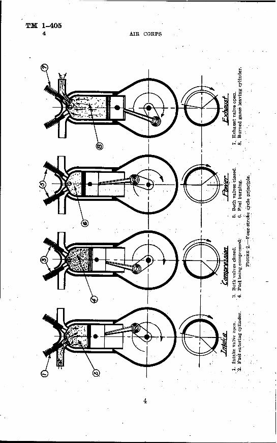
4. Four-stroke cycle principle.—a. In this type of engine, which is often called the four-cycle engine, the five events take place during four strokes, or two revolutions of the crankshaft (fig. 2). According to the strokes, the events take place in the following order:
(1) The first stroke is called the intake or admission stroke. The piston moves outward,' or toward the craiik, and admite a charge of the combustible mixture into the cylinder. During this stroke the intake valves are open.
(2) The second stroke is known as the compression stroke. The piston moves inward or from the crank, compressing the charge. At the end of the compression stroke the spark occurs and ignites the charge. During this stroke, both intake and exhaust valves are closed.
(3) The third stroke is known as the expansion or power stroke. The hot ignited gases create a high pressure on the piston and again move it outward, or toward the crank. Near the end of the stroke the pressure is much reduced by expansion, the exhaust valve opens, and the burned gas starts to scavenge out of the cylinder to the atmosphere.
(4) The fourth stroke is known as the exhaust, or scavenging stroke. The piston returns inward, or from the crank, and forces
TM 1-405 4 AIR CORPS

TM 1-405 AIRCRAFT ENGINES 4
out the burned gases left in the cylinder. At the end of the fourth stroke the piston again moves outward, admitting another charge of fuel and air mixture, thus starting another similar cycle of events.
b. In actual engine operation, a number of varying conditions must be considered in order to obtain the highest engine efficiency. These conditions are governed by the following rules:
(1) The larger the volume of a properly proportioned vaporized fuel and air mixture admitted into an engine cylinder, the more power developed, provided the charge is not compressed above the limiting pressure of the fuel.
(2) The larger the volume of exhaust gases expelled from an engine cylinder, the more power developed.
(a) _ By opening the intake valve before the piston has reached top center on the exhaust stroke, a larger volume of charge is admitted into the cylinder at the rpm at which the engine operates most of its useful life. This timing results in very poor efficiency at low rpm; however, the sacrifice is well worth the gain. By allowing the intake valve to remain open during the full length of the outward stroke and a certain portion of the inward compression stroke, the volume of charge admitted into the cylinder is still further increased. Therefore, the intake valve actually remains open during the entire intake stroke as well as part of the compression stroke.
(5) The exhaust valve opens when the piston is approximately two- thirds down the power stroke, which not only aids in obtaining better scavenging of burned gases, but results in better cooling of the cyl- inders. By allowing the exhaust valve to remain open the last one- third portion of the power stroke, the full length of the inward stroke, and approximately one-ninth of the next outward stroke, prac- tically all of the burned gases are expelled from the cylinder.
c. The igniting of the charge is a vital event in the operation of a conventional aircraft engine and must occur at the proper time. The igniting unit is therefore timed to ignite the charge before the piston reaches top center on compression stroke in order to allow suffi- cient time for the burning charge to reach its maximum pressure at the instant the piston passes over top center. Inasmuch as the rate of burning of the charge is dependent on its degree of compression, which in turn is governed largely by the volume of the charge admitted into the cylinder, or by throttle position, it becomes apparent that the time at which the charge is ignited should vary with the throttle in order to obtain maximum efficiencies at all engine speeds. The limited range of rpm at which an aircraft engine operates most of its useful life and the attendant dangers of operating on retarded

TM 1-405 4 AIK CORPS
1. Fresh gases being compressed. 4. Gases being compressed in crankcase. •' 2. Fresh gases entering crankcase. 5. Fresh gases entering, cylinder trom crankcase. 3. Gases burning in cylinder. 6. Burned gases leaping cylinder.
FIGUBE 3.—Two-stroke cycle principle. 6
TM 1-405 AIRCRAFT ENGINES 4-6
spark prohibit the use of a variable spark control. Therefore, the ignition unit is timed to ignite the charge at one piston position, which is in advanced position.
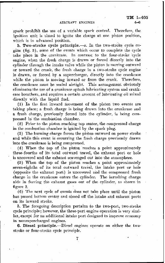
5. Two-stroke cycle principle.—a. In the two-stroke cycle en- gine (fig. 3), some of the events which occur to complete the cycle take place in the crankcase. In contrast to the four-stroke cycle engine, when the fresh charge is drawn or forced directly into the cylinder through the intake valve while the piston is moving outward or toward the crank, the fresh charge in a two-stroke cycle engine is drawn, or forced by a supercharger, directly into the crankcase while the piston is moving inward or from the crank. Therefore, the crankcase must be sealed airtight. This arrangement obviously eliminates the use of a crankcase splash lubricating system and crank- case breathers, and requires a certain amount of lubricating oil mixed directly with the liquid fuel.
(1) In the first inward movement of the piston two events are taking place; a fresh charge is being drawn into the crankcase and a fresh charge, previously forced into the cylinder, is being com- pressed in the combustion chamber.
(2) Prior to the piston reaching top center, the compressed charge in the combustion chamber is ignited by the spark plug.
(3) The burning charge forces the piston outward on power stroke and while this event is occurring the fresh charge previously drawn into the crankcase is being compressed.
(4) When the top of the piston reaches a point approximately three-fourths of its total outward travel, the exhaust port or hole is uncovered and the exhaust scavenged out into the atmosphere.
(5) When the top of the piston reaches a point approximately seven-eighths of its total outward travel, the intake port or hole (opposite the exhaust port) is uncovered and the compressed fresh charge in the crankcase enters the cylinder. The inrushing charge aids in forcing the exhaust gases out of the cylinder, as shown in figure 3.
(6) The next cycle of. events does not take place until the piston has passed bottom center and closed off the intake and exhaust ports on its inward stroke.
b. The foregoing description pertains to the two-port, two-stroke cycle principle; however, the three-port engine operation is very simi- lar, except for an additional intake port designed to improve economy in nonsupercharged engines.
6. Diesel principle.—Diesel engines operate on either the two- stroke or four-stroke cycle principle.
TM 1-405 ' 6-7 AIR CORPS
a. In the conventional engine an electric spark is utilized to ignite the mixture of gasoline and air to start combustion, whereas the Diesel engine generates its own heat to ignite or start combustion by means of highly compressed air.
b. In the Diesel engine, pure air is introduced into the cylinders! instead of a mixture of fuel and air as in the conventional engine; this air is compressed into a much smaller space than is possible when using a mixture of fuel and air, which would prematurely detonate if compressed to this extent. The temperature of the air in the cylin- der at the end of the compression stroke operating with a compression ratio of approximately 14:1 is about 1,000° F., which is far above the spontaneous ignition temperature of the fuel used. Accordingly, when fuel in a highly atomized condition is injected into the cylinder just before the piston reaches top center on the compression stroke, the fuel burns immediately upon coming in contact with the highly heated air, thus starting combustion. Combustion at this point acts on the piston in the same manner,as in the case of the conventional, engine. ;
o. In the place of the metering device which is used on a conven-;
tional engine for mixing and metering the gasoline and air in proper proportions, the Diesel engine,employs a fuel pump and nozzle that injects the fuel in an atomized condition into the cylinder at the time that combustion is desired. The quantity of fuel injected into the cylinder controls the amount of heat generated. In the conventional engine, the fuel and air mixture ratio must be kept reasonably con- stant and when the fuel supply is reduced for throttling purposes, the air must be correspondingly reduced. In the Diesel engine, the amount of fuel may be varied without varying the amount of air.
d. The fact that the air in a Diesel engine cylinder is compressed and heated to a comparatively high degree permits the use of liquid fuels of comparatively low volatility. Fuels corresponding very nearly to crude petroleum oil therefore are suitable for the Diesel engine. -
7. Compressing the charge.—a. In a conventional internal- combustion engine the mixture of fuel and air must be highly com- pressed in order to obtain efficient combustion and a reasonable amount of work. If the charge is ignited at atmospheric pressure, the combustion is slow and much heat is radiated and lost. The re- sulting pressure or power, due to the combustion of the charge, is relatively low. Thus, an engine compressing the charge to 100 pounds per square inch will only develop approximately 1 horse- power for every 4 cubic inches displaced by the piston, while com-

TM 1-405 AIRCRAFT ENGINES 7
pressing the charge to 140 pounds per square inch will increase the output to a point where 1.8 cubic inches of piston displacement will produce 1 horsepower. Some aircraft engines in use at the present time have compression ratios as high as 7.25 to 1. In general, it may be said that the power and efficiency of an internal-combustion en- gine increase with the degree of compression. Therefore, an aircraft engine with a compression of 150 pounds per square inch has a much higher output for a given size cylinder than an engine with a com- pression of only 110 pounds per square inch. Unfortunately, com- pression pressures are limited by the fuel used and the service for which the engine is intended. Hence, a compression pressure that would be highly desirable from an efficiency point of view would be impossible because of certain conditions. Extremely high compres-. sion pressures result in detonation and set up heavy stresses in the structural parts of the engine.
b. The effects of compression, up to certain critical limits, in in- creasing the actual efficiency and output of an engine are twofold.
(1) The compression produces heat, which aids in the vaporization of the fuel. •
(2) At the point of highest compression, the volume is at a mini- mum and combustion is accomplished more rapidly because of the smaller space through which the flame spreads.
c. The exact compression obtained in any cylinder depends upon a number of factors. The following are the most important:
(1) The ratio of the total volume of the cylinder to the compres- sion space. The compression pressure of the cylinder varies as the ratio of the volume of the clearance space, plus the volume swept by the piston to the clearance space. This ratio is known as the com- pression ratio, and in aircraft engines varies from 5 to 7. For ex- ample, in a cylinder having a piston displacement of 100 cubic inches and a combustion chamber space of 20 cubic inches, the compression
100 + 20 120 6 ratio is = =- or, as it is commonly written, 6:1.
20 20 1 (2) The pressure of the charge in the cylinder when the com-
pression process begins. The compression pressure in the cylinder varies as the initial pressure of the charge at the beginning of the compression stroke. The initial pressure is determined by the volume and density of the charge admitted to the cylinder, or volumetric efficiency.
d. In simple terms, volumetric efficiency is the volume of the charge admitted into the engine cylinder compared to piston displacement
424577°—42 2 Q

TM 1-405 7-^8 AIR CORPS
and is expressed as a percentage. For example, a volume of 95 cubic inches of charge admitted into a cylinder of ioO-cubicLirich dis-
95 placement has a volumetric efficiency of 95 percent,/ =0.95=95
100 percent. With the advent of superchargers incorporated or installed, on present day aircraft engines, the volumetric efficiency may be in-, creased above 100 percent, because the charge is forced into the cyl- inder at pressures above atmospheric. Thus, the higher the mani- fold pressure reading of an aircraft engine in operation, the higher the compression pressure of the charge, resulting in higher power output.
8. Horsepower calculations.—a. A convenient and frequently, used method of comparing the output of different engines is to desig- nate the number of cubic inches of piston displacement required per brake horsepower. This is obtained by dividing the total cubic-inch piston displacement by its rated brake horsepower. In many auto- motive racing engines and aircraft engines this figure varies from 1.5 to 4 cubic inches per horsepower, and in some cases is as low as 1 cubic inch, because of the high compression pressures and piston speeds. Much depends on the volumetric efficiency. With the high tempera- tures and restrictions of the induction system experienced with some cylinders, the volumetric efficiency is seriously affected. The use of two inlet and two exhaust valves per cylinder and supercharging greatly increases the volumetric efficiency, with a corresponding in- crease in the power per unit of displacement volume.
b. In the inward movement of the piston in an engine cylinder, a specific volume is displaced from its upper extreme to its lower ex- treme position on the admission or intake stroke. This space or volume displaced by the piston is called "piston displacement," and consists of the product of the area of the cylinder bore and the length of the stroke of the pistons. In case of multiple-cylinder engines, this product is multiplied by the number of cylinders comprising the engine and may be expressed by either of the following formulas: ;
Displacement=0.7854 Z>2 LN (all dimensions in inches).:
Displacement=3.1416 R2 LN (all dimensions in inches). Where D = Cylinder diameter, ■'
L=Piston stroke, N= Number of cylinders, R= Cylinder radius. '
10

AIRCRAFT ENGINES TM 1-405
8
Employing the first formula, the piston displacement of a 12-cylinder engine having a 5-inch bore and 7-inch stroke would be computed, as follows: '
0.7854 X 52 X 7" X12=1,649.34 cubic inches o. Low weight per horsepower is an essential requirement for air-
craft engines; therefore, it is quite natural that weight per horse- power should be a basis used for comparing engines. The term "weight per horsepower" may be applied to an engine with four different meanings.
(1) Dry weight of complete engine with carburetors, air stack, magnetos, and pumps.
(2) Weight with attached accessories such as magnetos, carburetors, and pumps, and with coolant in the cylinder jackets, connecting pipes, and coolant pump.
DETONATION
B.C.- B.C.
FIGURE 4.—Recorded indicator card pressures.
(3) Weight with attached accessories such as radiators, tanks, bat- teries, and instruments, or, in other words, the entire power plant.
(4) Weight including all accessories and supplies. This basis is the most important and is dependent upon the length of required flight and fuel and oil consumption of the engine.
d. In comparing engines it may be found that an engine light in weight may prove to be low in horsepower or an engine high in horse- power may be heavy; therefore, it is essential that, in addition to weight per horsepower, the horsepower per cubic inch of piston dis- placement be known.
(1) Horsepower per cubic inch of piston displacement is dependent on the brake mean effective pressure (b. m. e. p.), or the average con- stant pressure which may be substituted to produce the same work as
11

TM 1-405 8 AIR CORPS
the actual varying pressures.. Brake mean effective pressure is derived from the brake horsepower measured by the use of a Prony brake, a calibrated club, or dynamometer. The indicated mean effective pressure of an engine may be obtained by recording the cylinder pres- sures by means of an indicator card apparatus (fig. 4), and is always higher than brake mean effective pressure, because the latter includes the power necessary to overcome the friction of the various moving parts.
(2) The difference, then, between indicated horsepower (I. H. P.) and brake horsepower (B. H. P.) is designated as friction horsepower (F. H. P.) which can only be obtained from actual brake test. By knowing any two of these three horsepowers, the third may be obtained by the use of the following formula:
B. H. P.=I. H. P.-F. H. P.
(3) Friction horsepower ranges from 4 to 10 percent of the total power developed in the engine cylinders. It determines the mechani- cal efficiency of the engine which is expressed as a percentage and varies in aircraft engines from 90 to 96 percent.
e. The horsepower of an engine varies with its speed; therefore, without changing the weight of an engine, the horsepower may be increased by increasing the speed up to a certain limit. Consider. next the effect of engine speed upon engine weight. It is evident that, in general, the higher the speed, the lower will be the engine weight per horsepower. The effect of engine speed upon engine reliability and engine life is important. At higher speeds, the reliability and the life of an engine are lessened.
/. When the B. H. P. is obtained by brake test, the b. m. e. p. may be calculated by the use of the following formula:
33,000 b. m. e. p.=B. H. P. X _ ' _ r LAN
Where L= Stroke in feet, A= Bore in square inches, N= Power strokes per minute.
In a four-stroke cycle engine, N is one-half the engine rpm multi- plied by the number of cylinders. The number 33,000 remains con- stant (33,000= foot pounds per minute=l H. P.).
g. Energy is neither created nor destroyed. The actual efficiency of an engine is the ratio of the power developed to the energy fur-' nished in the form of heat from fuel-charge combustion. This ratio is necessarily low because of several factors. To prevent the metals
12

TM 1-405 AIRCRAFT ENGINES 8
used in the construction of the cylinders from melting, a large amount of heat must be dissipated through cooling, conduction, radi- ation, and exhaust. As previously stated, a small amount is utilized in overcoming friction of moving .parts, etc. Considering the total heat supplied as 100 percent at full throttle and full load, the various losses may be divided as follows:
Percent
Heat loss through exhaust 30 Heat loss through cooling, conduction, and radiation 30 Heat loss through friction (including pumping losses and
determined by mechanical deficiency) 6 '
Total heat loss 66
If the total heat loss is 66 percent, then the energy available for power is only 34 percent. Although the percentage of heat losses has been reduced in the past few years, particularly in reducing friction, no further appreciable reductions may be expected from present-day conventional engines. Increased power per cubic inch of piston dis- placement has been obtained by increasing the total amount of heat supplied by an improvement in fuels, which permits higher volumetric efficiencies and higher compression ra-tios.
k. In summing up the fundamental power factors which determine the actual efficiency of an engine (excluding engine speed), it is noted that the compression ration, the volumetric efficiency, and the kind of fuel and mixture strength greatly affect the heat of combustion. If only 34 percent of this heat at full throttle, full load operation, is utilized as work in rotating the propeller, it is of interest to note that an aircraft engine which consumes 100 gallons of gasoline per hour utilizes only 34 gallons in actual work.
SECTION II
CLASSIFICATION AND DESCRIPTION OF ENGINE TYPES
Paragraph General 9 In-line type 10 V-type 11 Double V- or fan type : 12 X-type 13 Opposed or flat type ■■-- 14 Radial type ,-. ; 15 Cylinder numbers : 16 Firing orders , 17 '
13

TM 1-405 9-13 AIR CORPS
9. General.—a. Aircraft engines may be divided into two general classes, liquid-cooled and air-cooled. Although the air-cooled engine has been more generally used in the past, the modern liquid-cooled engine is increasing in popularity, due to its excellent streamlining characteristics and the ease with which its heat may be dissipated.
b. Either of the above classes may be further divided into types, based on the arrangement of the cylinders with respect to the crank- case. These types are illustrated in figure 5.
(1) The most common types of air-cooled engines are radial (single or double row), in-line, and opposed.
(2) The most common types of liquid-cooled engines are V, in-line, opposed, X, and double V.
10. In-line type.—The cylinders of the in-line type engines are arranged in a single row on the crankcase, either in an upright or inverted position. Although this type is not suitable for use where high horsepower output is required, it is an entirely satisfactory design for low-performance airplanes. Practically all of the mod- ern in-line engines are of the inverted type. This method of con- struction is particularly advantageous from the standpoint of stream- lining and visibility. The high position of the propeller shaft in the inverted engine also allows for low landing gear design due to the increased propeller clearance. The maximum number of cylinders in in-line engines is usually limited to six, to facilitate cooling and avoid prohibitive weight per horsepower.
11. V-type.—The cylinders of V-type engines are arranged on the crankcase in two rows or banks forming a V. The two banks of cylinders are directly opposite each other, which permits two sets of connecting rods to operate on the same crankpin. This arrange- ment greatly reduces the weight per horsepower as compared to the in-line type, with very little sacrifice in the head resistance of the aircraft. A typical engine of this type is illustrated in figures 6 and 7.
12. Double V- or fan type.—In an attempt to raise the limit of available horsepower per unit of weight, a double V-type, liquid- cooled engine has been developed, which consists of four banks of cylinders arranged in a fan shape. The chief advantage in such an engine is that it gives practically the same horsepower as two single V-type engines without materially increasing the frontal area required for a single V-type engine. The two crankshafts are employed to drive the propeller.
13. X-type.—In the X-type engine two of the four banks of cylin- ders are arranged on one side of the center line of the engine while
14

AIRCRAFT ENGINES TM 1-405
13-14
the other two are equally spaced on the opposite side in the form of the letter X. This arrangement permits the use of only one crankshaft in contrast to the two crankshafts in the double V-type.
14. Opposed or flat type.—In the opposed type engine the cylin- der banks are arranged horizontally, in two rows, on opposite sides
r\
(A) (B)
IN-LINE TYPE V-TYPE
(c)
DOUBLE V-OR FAN TYPE
C D
OPPOSED OR f LAT TYPE
X-TYPE
FIGURE 5.-
(0 • (P) SINGLE ROW DOUBLE ROW
RADIAL TYPE RADIAL TYPE -Typical aircraft engine cylinder arrangement.
of the crankcase. A single crankshaft of conventional design is em- ployed and the engine may be constructed with any even number of cylinders. Due to the flat shape of the engine, it is particularly adaptable for streamlining and makes possible wing engine installations.
15

TM 1-4G5 15-16 AIR CORPS
15. Radial type.—a. In single-row radial engines the cylinders extend radially from the center line of the crankshaft in any odd. number, usually between 3 and 9. The cylinders are evenly arranged- in the same circular plane. A single-throw, 360° crankshaft is used; , to which all of the connecting rods are attached resulting in a mini- ■■ num number of working parts as well as a considerable saving in weight.
b. The double-row radial engine resembles two single-row engines combined on a single crankshaft. The conventional number of cylinders used is either 14 or 18, which in effect would be either two
FIGURE 0.—Kight roar view of typical V-type engine.
7:cylinder engines or two 9-cylinder engines. A two-throw, 1-80° crankshaft is used to permit the cylinders of each row to be alter- nately staggered on the common crankcase. This alternate staggering allows the cylinders in both the front and rear rows to receive sufficient air from the slip stream for proper cooling. A typical double-row radial type engine is illustrated in figures 8 and 9.
16. Cylinder numbers.—The numbering of engine cylinders is by no means standard in procedure. Some manufacturers number their engines from the drive end and some from the opposite end.
16

AIRCRAFT ENGINES
TM 1-405 16-17
In-line and V-type engine cylinders are usually numbered from the end opposite the propeller shaft, as shown in figures 10, 11, and 12. Kadial-type engines usually have their cylinders numbered counter- clockwise as viewed from the propeller shaft end, number one being the top or vertical cylinder. The usual cylinder numbering of both single- and double-row radial engines is illustrated in figures 13 and 14.
17. Firing orders.—a. The order in which1 firing impulses take place in any internal-combustion engine depends upon the type and
FIGLT.E 7.—Lett front view of typical V-type engine.
design. The following factors are the most important features which govern the firing order: .
(1) Primary factors. (a) Number of cylinders to be fired. (b) Arrangement of cylinders on the crankcase. (c) Direction of rotation of the crankshaft. (d) Crankshaft type. (2) Secondary factors. (a) Type and arrangement of the cam mechanism. (b) Design of the induction system. (c) Desirability of minimum stresses obtainable througTi a logical
order of firing impulses. b. Figures 10 to 14 inclusive illustrate the most logical firing orders
of conventional engines. 424577°—42 3 17

TM 1-405 17 AIR CORPS
18

AIRCRAFT ENGINES
TM 1-405 17
er a cö
HS s
U.6;
i I s 1 31 8fH H _ ^ u v' - - -? O •" — -3" a z z Ä t- o < H « u s a
•n .,i T 2: IJJ .■> O ? il < i O a O o o rr m o
19

TM 1-405 17 AIR CORPS
I8(f CRANKSHAFTS WITH TWO CENTER THROWS IN LINE AND TURNING ANT I - CLOCKWISE FROM
THE PROPELLER END
CAMSHAFT MECHANISMS DIFFERENT
o © © 0
o © © 0
FIRING ORDER I 3 4 2
FIRING ORDER I 2 4 3
FIGURE 10.—Cylinder numbering and firing order of 4-cylinder in-line engine.
120 CRANKSHAFT TURNING ANTI- CLOCKWISE FROM THE PROPELLER
END
o 0 © 0 ©
FIRING ORDER
15 3 6 2 4 FIGURE 11.—Cylinder numbering and firing order of 6-cylinder in-line engine.
20

TM 1-405 AIRCRAFT ENGINES 17
I20°CRANKSHAFT TURNING ANTI- CLOCKWISE FROM THE PROPELLER
END
RIGHT BANK
o LEFT BANK
o 0 0 0 0 0 0 0 0 0 0
PROPELLER
FIRING ORDER
IL 6R 5L 2R 3L 4R 6L IR 2L 5R 4L 3R
FIGURE 12.—Cylinder numbering and firing, order of 12-eylinder V-type engine.
SECTION III
DESCRIPTION AND CONSTRUCTION OF ENGINE UNITS Paragraph
General 18 Cylinders " 19 Valves and valve springs '. 20 Valve mechanism ~ 21 Piston assemblies 22 Connecting rods 23 Crankshaft assemblies 24 Bearings \ 25 Internal blowers or superchargers 26 Crankcase assemblies 27 Intake manifolds . 28 Exhaust manifolds 29 Coolant pumps 30 Oil pumps and relief valves 31 Fuel pumps 32 Vacuum pumps ; 33 Engine accessories 34
21

TM 1-405 IT
z =- <s o ° z * z 3 I
J-2Z u. o ui x u. (0 * ui z </>
«1 °°3 2 d
I IT
Z -I
<£ o o z a. z* => I H |-
X U. CO * u z <2
S3
AIR CORPS
(W \ / — O
fO / O W |
u a
( - -0> } UI Q
8
3
12
g a
nd
flri
n
radia
l en
gi
lae K > \° u
a c
<0
13
nib
erin
le
-row
E
P J3
( N r>- ) u.
fl> |s S3 T3
'■? a m
(* \ /*
2 ££ -. ■*' IT» rH
o g — S
© F-i
s GO ÖÄ aj
s s ( ** . <o ä'%
ce UI
IB <o ) a a: O /"
(- /K\
z 0> i S
is. s Ä Bt
FJ S
/o.\ in )
5 u.
(0 3 'S f» a v s
I t?
«<)
22
TM 1-405 AIRCRAFT ENGINES 18-19
18. General.—In the construction of an internal-combustion en- gine, reliability of the working parts is of major importance. This generally requires the use of strong and, at times, heavy materials which result in a bulky and heavy engine. The major problem in air- craft engine design is. to construct the parts strong and light and still retain reliability. All moving parts must be carefully machined and balanced to reduce vibration and fatigue to a minimum, especially in engines which operate at a relatively high speed. In the construction of aircraft engines, every detail must be worked out to obtain a unit •which is of good design, reliable in operation, low in weight per horsepower, and comparatively economical in fuel and oil consump- tion. The description and construction principles of the major units of an engine given in the paragraphs below apply particularly to aircraft engines.
19. Cylinders.—a. The cylinder is the most important unit of an engine and is that part in which the power is developed to accom- plish work. Basically, the type of cylinder designed for aircraft en- gines has not changed to any great extent during the past few years and is still known as the I or overhead valve type. Structurally, there has been a vast number of detailed improvements, particularly in the air-cooled cylinder.
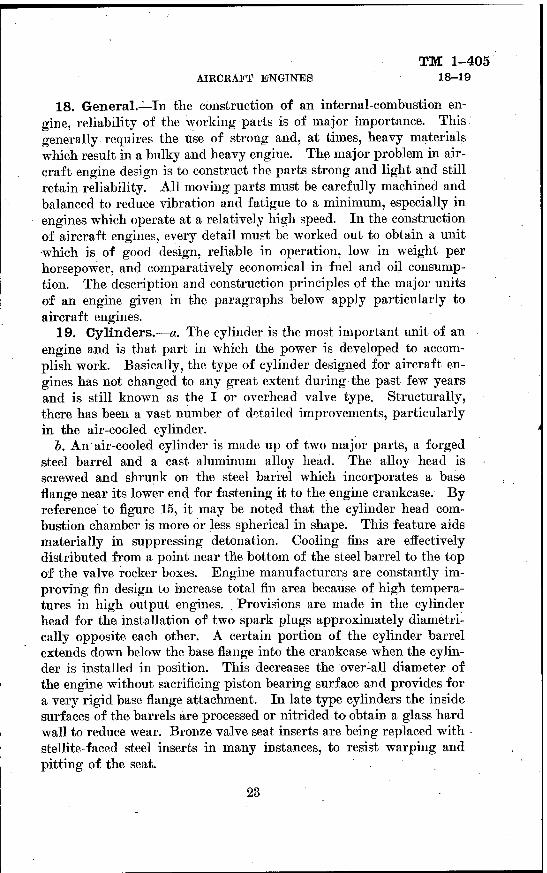
b. An air-cooled cylinder is made up of two major parts, a forged steel barrel and a cast aluminum alloy head. The alloy head is screwed and shrunk on the steel barrel which incorporates a base flange near its lower end for fastening it to the engine crankcase. By reference to figure 15, it may be noted that the cylinder head com- bustion chamber is more or less spherical in shape. This feature aids materially in suppressing detonation. Cooling fins are effectively distributed from a point near the bottom of the steel barrel to the top of the valve rocker boxes. Engine manufacturers are constantly im- proving fin design to increase total fin area because of high tempera- tures in high output engines. , Provisions are made in the cylinder head for the installation of two spark plugs approximately diametri- cally opposite each other. A certain portion of the cylinder barrel extends down below the base flange into the crankcase when the cylin- der is installed in position. This decreases the over-all diameter of the engine without sacrificing piston bearing surface and provides for a very rigid base flange attachment. In late type cylinders the inside surfaces of the barrels are processed or nitrided to obtain a glass hard wall to reduce wear. Bronze valve seat inserts are being replaced with stellite-faced steel inserts in many instances, to resist warping and pitting of the seat.
23

TM 1-405 19 AIR CORPS
c. In liquid-cooled engines, several steel cylinder barrels are se- curely installed in a cast aluminum alloy assembly which incorporates passages and jacket space for the circulation of the coolant around
1. Exhaust valve. 2. Steel cylinder barrel. 3. Cylinder base flange. 4. Valve seat inserts. 5. Intake valve. 6. Piston on intake stroke, intake valve open. 7. Aluminum alloy head.
FIGURE 15.—Air-cooled cylinder.
the cylinders and valves. The complete unit is called a cylinder bank assembly. There is usually one bank for each row of cylinders. The cylinder base flange is part of the lower jacket assembly and, although the upper jacket or head assembly appears to be detachable, once it is
24
AIRCRAFT ENGINES
TM 1-405 19-20
installed it actually becomes an integral part of the cylinder bank and is not to be removed, except when replacing worn cylinder barrels. The combustion chamber may be either spherical or roof-shaped and incorporates bronze or stellite-faced steel valve seat inserts.
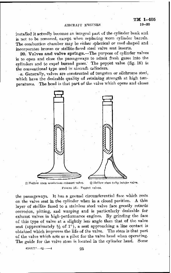
20. Valves and valve springs.—The purpose of cylinder valves is to open and close the passageways to admit fresh gases into the cylinders and to expel burned gases.' The poppet valve (fig. 16) is the conventional type used in aircraft cylinders.
a. Generally, valves are constructed of tungsten or silchrome steel, which have the desirable quality of retaining strength at high tem- peratures. The head is that part of the valve which opens and closes
Q
u i£ j.
3
® Hollow stem mushroom exhaust valve. © Hollow stem tulip intake valve.
FIGURE 16.—Poppet valves.
the passageways. It has a ground circumferential face which rests on the valve seat in the cylinder when in a closed position. A thin layer of stellite fused to a stainless steel valve face greatly retards corrosion, pitting, and warping and is particularly desirable for exhaust valves in high-performance engines. By grinding the face of this type of valve at a slightly less angle than that of the valve seat (approximately y2 of 1°), a seat approaching a line contact is obtained which improves the life of the valve. The stem is that part of the valve which acts as a pilot for the valve head when operating. The guide for the valve stem is located in the cylinder head. Some
424577°—42- 25

TM 1-405 20-21 AIR CORPS
exhaust-valve stems are hollow and filled with a salt solution, mer- cury, or metallic sodium to assist in reducing the operating tempera- ture of the valve head. Exhaust valves, particularly in air-cooled engines, are constructed with heavier heads and larger diameter stems than intake valves to withstand the high temperatures at which they operate.
b. The valves are opened by cams and closed by co.iled springs. In aircraft engines, two or more springs may be used on each valve. The use of multiple valve springs promotes operating safety, equal- izes side pressure on the valve stem, permits a higher spring tension within a restricted area, and prevents valve-spring surging. The most important advantage of multiple valve springs is the elimina- tion of valve spring surging. When one spring tends to vibrate at cam speeds of 1/2? %, %, etc., of its natural period, the other spring or springs, having a different vibrational period, tend to "damp out" the vibration. The valve springs are compressed to position over the valve stems and securely held in place by a locking device.
21. Valve mechanism.—a. The valve mechanism of an engine consists of the parts which operate the valves, the number of parts depending upon the arrangement of the cylinders on the crankcase and the location of the valves. In aircraft engines the valves are located in the head of the cylinder to obtain maximum efficiency.
b. In single-row radial engines, the valve mechanism consists of a cam plate located in the nose section of the crankcase and driven by the crankshaft indirectly through a cam-drive gear, cam follower, push rod, and rocker arm. The cam plate, as shown in the nose sec- tion in figure 17, employs two rows, each containing four cam sur- faces, one row operating the intake valves and the other row operating the exhaust valves.
(1) In double-row radial engines two cam plates are employed, one in the nose section which operates the valves of the front row of cylinders, and the other in the rear section for the rear row of cylin- ders. In some instances a singlerrow cam plate is used in place of a two-row cam plate. In such cases both valves remain open an equal number of degrees of crankshaft travel.
(2) Hardened steel cam follower rollers, running on the cam plate or ring, operate rocker arms through the medium of push rods. The rocker arms mounted in rocker boxes on the cylinder head operate the valves. Figure 18 shows the arrangement of the push-rod and rocker-arm assembly of a radial engine.
26

AIRCRAFT ENGINES TM 1-405
21
c. In V-type aircraft engines the valve mechanism consists of one or two camshaft assemblies mounted over the valves on the head of each cylinder bank.
FIGURE 17.—Radial engine valve mechanism.
(1) When two camshafts are used, one operates the intake valves and the other operates the exhaust valves. Both camshafts are usually driven by one common idler gear, which in turn is driven by
27

TM 1-405 21 AIR COUPS
FIGüBE 18.—Radial engine push-rod and rocker-arm assembly.
28

TM 1-405 AIRCRAFT ENGINES 21-22
the crankshaft indirectly through a gear train. Where each cam operates two valves, a T-shaped tappet is interposed between the cam and the two valve stems to provide a means for the cam to operate the two valves simultaneously. ^
(2) When only one camshaft is used on each cylinder bank, it is driven directly by the crankshaft through a vertical driveshaft and conventional bevel gears. Each intake and exhaust cam operates two intake and two exhaust valves through a unique rocker arm arrangement.
(3) Camshafts are generally machined from a silchrome steel forging, with the cams heat-treated to obtain a hard-wearing sur- face where they contact the valve tappets or rollers. Light alloy bearings attached to the cylinder head support the camshafts and are lubricated through the hollow camshaft journals.
22. Piston assemblies.—a. The piston in an engine serves as a plunger in admitting a fuel charge into the cylinder, compressing the mixture, transmitting the work accomplished by combustion to the crankshaft, and expelling the burned gases from the cylinder. Engine pistons are constructed of a light aluminum alloy,which reduces operating stresses to a minimum and permits a rapid con- duction of heat away from the piston head to adjoining engine parts for radiation. This results in a comparatively low piston operating temperature. A low temperature of the piston results in a low heat transfer to the incoming charge during the intake stroke, thereby increasing the volumetric efficiency of the engine and permitting a high compression ratio without detonation. Pistons are forged or die-cast under pressure, producing a strong, durable unit. Each piston is carefully machined to a uniform weight to reduce vibration to a minimum. A typical piston assembly is shown in figure 19.
(1) The piston head may be flat, convex, or concave, and in some .instances recesses are machined in flathead pistons for use in high compression engines to permit the valves to open without interfer- ence. Insofar as efficiency of operation is concerned, it makes little difference which type is used. The inside of the head is usually ribbed for strength and to permit a high heat transfer to the crankcase.
(2) There are usually four grooves in the piston head to accommo- date three compression rings and one oil-control ring. The lowest of these four grooves is for the oil-control ring. It is drilled through at several points to allow surplus oil from the cylinder wall to be forced into the crankcase by the oil-control ring. A groove in the piston skirt,
29

TM 1-405 22 AIR CORPS
1. Piston head. 2. Compression rings. 3. Oil-control ring. 4. Pin retainer.
5. Piston bosses. 6. Piston pin. 7. Piston skirt. 8. Oil-wiper ring.
PlGUEE 19.—Typical piston assembly.
below the piston pin, accommodates an oil-wiper ring which assists the oil-control ring in preventing excessive oil consumption.
(3) The sidewalls, or the skirt of the piston, act as a guide or bear- ing surface for the head and incorporates the piston pin bosses, which are of heavy construction and usually ribbed to carry the piston pin load.
5. The purpose of piston rings is to prevent leakage of gas pres- sure from the combustion chamber and to reduce to a minimum the
~2ZL FIGCUE 20.—Diagonal cut concentric piston ring.
30

AIRCRAFT ENGINES TM 1-405
23
seepage of oil into the combustion chamber. The rings fit into the grooves of the piston which hold them square against the cylinder walls. The majority of piston rings are constructed of a good grade of grey cast iron. They must be capable of exerting sufficient spring pressure against the cylinder wall to perform their function with a minimum of friction. The gap in the piston ring, where it butts together when in position in the cylinder, may be diagonal, step, or butt cut. Only a small portion of gas seepage occurs at the piston ring gap, regardless of the shape of cut. Piston rings are concentric and are of uniform thickness (fig. 20).
c. The oil-control ring is usually similar in construction to a com- pression ring. However, some manufacturers use two thin rings as shown in figure 21®. They are milled out at intervals on the lower side to permit seepage of the surplus oil from the cylinder wall to
PISTO •-CYLINDER
COMPRESSION OIL CONTROL RINGS RINGS
® ® ® FIGURE 21.—Cross section of piston rings.
OIL WIPER RING
©
flow freely back into the crankcase through the drilled holes in the groove. An oil-wiper ring, beveled on its outside circumference, is shown in figure 21®. It is installed with the bearing edge toward the crankcase to allow the ring to wipe off surplus oil from the cylinder wall as the piston moves on its outward stroke. Modern types of compression rings are similar to oil-wiper rings, but with only a slight bevel, as shown in figure 21®. This design was found necessary with the advent of nitralloy cylinder barrels in order to hasten proper seating of the ring. This ring becomes more efficient as its life increases.
d. The piston pin connects the piston assembly to the connecting rod and is machined from a nickel steel alloy forging, case-hardened, and ground. The pin is made hollow for lightness. The type used
31

TM 1-405 22-24 AIR CORPS
in aircraft pistons is free to move in bearings in the piston and in the small end of the connecting rod, and is known as the full floating type. It may be held in place by aluminum plugs or spring locks which prevent it from scoring the cylinder walls. Oscillating and stationary types of piston pins are used principally in automotive engines. The oscillating type is fastened securely to the small end of the connecting rod and oscillates in the piston boss. The stationary type is securely fastened in the piston boss, and the small end of the connecting rod oscillates on the pin. The latter types mentioned do not have as much bearing surface as the full floating pin.
23. Connecting- rods.—a. The connecting rod is that part which connects the piston assembly to the crankshaft. It transmits the power developed from combustion on the piston to the crankshaft. Connecting rods are classified according to their shape and arrange- ment on the crankshaft. They also vary in cross section, some being tubular and others I or H section. Three general types, classified by their bearing arrangement on the crankshaft, are the plain, the ar- ticulated, and the forked and blade types. Connecting rods are usu- ally constructed "of chromium-nickel steel. The small end of the connecting rod is connected to the piston by the piston pin, and the large end is connected to the crankpin of the crankshaft.
b. The plain type of connecting rod is a single rod of conventional design and is seldom used in high output aircraft engines, because it necessitates the use of a long, heavy crankshaft, resulting in a heavy engine. Side by side mounting of plain type connecting rods is often used in small opposed type aircraft engines.
c. The articulated type of connecting rod is used extensively in radial- and V-type aircraft engines and is constructed of a master rod having one or more short rods attached to the large end with link pins. This arrangement permits the construction of a short, light- weight engine, without sacrificing reliability of operation.
d. The forked and blade type of connecting rod may also be em- ployed on V-type engines and consists of two rods operating together on each crankpin. One rod is a blade type and the other a forked type. In some V-type engines the forked rod carries the crankpin bearing while the blade rod oscillates between the forks on the outside surface of the bearing. On other V-type engines the blade rod carries the crankpin bearing, the forked rod straddling the blade rod on the outside surface of the bearing.
24. Crankshaft assemblies.—a. The crankshaft is that part of the engine which receives the power developed on the piston and, in aircraft engines, delivers it to the propeller in a rotary motion. The
32

AIRCRAFT ENGINES TM 1-405
24
STROKE LENGTH
TRAVEL PATH OF ARTICULATED LINK ROD PIN CENTER IN ONE REVOLUTION W CRANKSHAFT
CRANKPIN TRAVEL PATH
® Articulated type.
STROKE LENGTH
A_
CRANKPIN TRAVEL-
PATH
© Forked and blade type.
FIGURE 22.—V-type engine connecting rods.
424577°—42 5 33

TM 1-405 24 AIR CORPS
three most commonly used crankshafts are the 360°, 180°, and 120° types. All types are usually constructed of chrome-nickel steel. The crank journal is that part which rotates in the main bearings, and the crankarm or cheek is that part which connects the crankpin to the journal. Figure 24 illustrates the various types of crankshafts.
STROKE LENGTH
A,-
B, •
S35^ HEAD
FIGURE 23.—Radial-type engine articulated connecting rod.
(1) The 360°-type crankshaft is conventional for all single-row radial aircraft engines. This type of crankshaft (fig. 25) employs two counterweights, one on each crankcheek, to counteract torsional vibra- tion. In high-powered engines, a dynamic damper or pendulum
34

AIRCRAFT ENGINES TM 1-405
24
I ^CRANKPIN
JOURNAL- ^
«-CRANKARM i RCAR ROW
fts=n
T"
e^^-m^
\i«0
/' H v —H*0 S leeiL-
REAR^-^ROW
114
<t^3
3&4
20 ^ I20
2 &5V VIM ~I2CT ̂
FIGURK 24.—Various types of crankshafts.
IS&J
r**:. JUS «,:
' IIS #1
^3*8 te! ?«K"
FIGDUE 25.—A typical 360° crankshaft.
35
TM 1-405 24 AIR CORPS
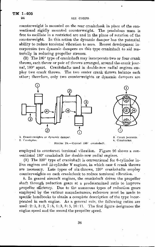
counterweight is mounted on the rear crankcheek in place of the con- ventional rigidly mounted counterweight. The pendulous mass is free to oscillate in a restricted arc and in the plane of rotation of the counterweight. In this action the dynamic damper has the potential ability to reduce torsional vibration to zero. Recent development in- corporates two dynamic dampers on this type crankshaft to aid ma- terially in reducing propeller stresses.
(2) The 180° type of crankshaft may incorporate two or four crank throws, each throw or pair of throws arranged, around the crank jour- nal, 180° apart. Crankshafts used in double-row radial engines em- ploy two crank throws. The two center crank throws balance each other; therefore, only two counterweights or dynamic dampers are
1. Counterweights or dynamic damper. 2. Crankpins.
FIGURE 26.—Typical 180° crankshaft.
3. Crank journals. 4. Crankarms.
employed to counteract torsional vibration. Figure 26 shows a con- ventional 180° crankshaft for double-row radial engines.
(3) The 120° type of crankshaft is conventional for 6-cylinder in- line engines and 12-cylinder V engines, in which case 6 crank throws are necessary. Late types of six-throws, 120° crankshafts employ counterweights on each crankcheek to reduce torsional vibration.
b. In geared aircraft engines, the crankshaft drives the propeller shaft through reduction gears at a predetermined ratio to improve propeller efficiency. Due to the numerous types of reduction gears employed by the various manufacturers, reference must be made to specific handbooks to obtain a complete description of the type incor- porated in each engine. As a general rule, the following ratios are used: 2:1, 3 : 2, 7: 5, 4: .3, 8: 5, 16:11. The first figure designates the engine speed and the second the propeller speed.
36

AIRCRAFT ENGINES TM 1-405
24-25
Bearing
Roller Bearings
1. Outer race. 4. Lead-bronze. 2. Inner race. 5. Steel shell. 3. Rollers. 6. Ball.
FIGURE 27.—Various types of radial bearings.
25. Bearing's.—-a. Bearings are classified in three groups, plain, roller, and ball. The purpose of bearings is to reduce, insofar as practicable, metallic friction to a minimum. Figure 27 illustrates representative types of radial bearings.
b. Plain type bearings are generally employed in engines as main, connecting-rod, camshaft, and driveshaft bearings, because of their reliability and the ease with which they may be adjusted. Plain type bearings may be constructed in two parts, an upper and a lower half, and securely fastened together by bolts or screws; or in one piece, pressed or shrunk in position. These bearings are usually constructed of a nonferrous metal, such as copper-lead, babbitt, aluminum, brass, or bronze; or a combined nonferrous and ferrous metal, such as bab-
^
W £jn
w i'<~*e-
L*-*v J. -. 1^-^-.
INDICATES DIRECTION OF THRUST
FIGURE 28.—Types of thrust bearings.
37

TM 1-405 25-26 AIR CORPS
bitt or copper-lead, and steel. For heavy-duty, high-speed work, such as encountered in connecting-rod and main bearings, a babbitt or cop- per-lead alloy is used as the bearing surface and is backed with bronze or steel for strength. For light-duty, slow-speed work, such as en- countered in camshaft or driveshaft bearings, plain babbitt, bronze, brass, or aluminum is satisfactory.
c. Roller bearings may be used as main bearings in the construction of radial aircraft engines, but in other type engines they are used only in accessories, such as starters and superchargers. Roller bearings can be made more adaptable for heavy loads than ball bearings due to their greater surface contact, but at a sacrifice of increased friction. However, roller bearings cause less friction than plain bearings.
d. Ball bearings are used extensively in aircraft engine construc- tion, particularly in engine accessories, such as ignition units, gen- erators, starters, and superchargers. Annular ball bearings are gen- erally constructed of hardened steel balls operating between an inner and outer ball race and are assembled in such manner that the balls cannot fall out of position. Less friction occurs in ball bear- ings than either the plain or roller bearings. Ball bearings require less lubrication, although the highly polished ball surfaces are sub- jected to corrosion and pitting, especially when not in constant use.
e. In aircraft engines, annular ball bearings are used as thrust bearings. Figure 28® illustrates a type of ball thrust bearing (generally employed in pairs) which takes thrust in one direction only and is commonly used in supercharger drives, whereas the thrust bearing illustrated in figure 28© takes thrust in both direc- tions and is commonly used on propeller driveshafts. These bearings are nonadjustable and in addition to taking thrust will support sub- stantial radial loads.
26. Internal blowers or superchargers.—a. Internal blowers were originally incorporated in radial engines to distribute the fuel and air mixture uniformly to all cylinders, a function it still per- forms; however, with the advent of improved fuels, the speed ratio has been increased to such an extent that the blowers are called superchargers.
b. The blower or supercharger consists of a dynamically and stati- cally balanced light alloy impeller operating within an aluminum alloy housing incorporating fuel charge passages from the carburetor to the intake pipes and forming part of the engine crankcase as- sembly. Either a vaneless or vaned diffuser type plate is used in con- junction with the impeller to convert the high velocity of the charge, caused by the high rotational speed of the impeller, to pressure be-
38

TM 1-405 AIRCRAFT ENGINES
fore entering the intake pipes and cylinders. The impeller is mounted on a steel shaft and is driven through suitable gearing by the crankshaft. Figure 29 illustrates a vaned type diffuser plate and impeller mounted in position.
c. Due to the high speed at which an impeller is driven, it is neces- sary to incorporate some means of relieving the stresses in the impeller drive gears when the engine is suddenly accelerated or decelerated.
*Kt .?*».£•!&' "
FIGURE 29.—Vaned diffuser type plate and impeller.
This is usually accomplished by a flexible coupling between the engine crankshaft and impeller gearing. This coupling, sometimes called a spring drive, relieves gear stresses because of its cushioning effect by the transmission of the rotative force to the driven gear through springs spaced concentrically around the driving shaft. In some engines a coupling using engine oil under pressure for cushioning
39

TM 1-405 26-27 AIR CORPS
effect is used. The oil is forced between vanes connected to the crank- shaft by means of suitable gearing which transmits the load to the drive gear of the supercharger by means of anchored weights attached to the gear.
d. The speed ratio at which the impeller is driven by the crankshaft varies according to the diameter of the impeller and the degree of supercharging desired. In general, small diameter impellers are driven at ratios as high as 14:1 and large diameter impellers at ratios as high as 10:1. The first figure designates the impeller speed and the second, the engine speed. In addition, the large diameter impeller may have wide or narrow vanes (fig. 30).
e. Some modern high performance engines, used for high altitude flying, are equipped to operate on either a low or high blower ratio.
LARGE DIA. IMPELLER
SMALL DIA. IMPELLER
NARROW IMPELLER
WIDE IMPELLER
FIGURE 30.—Impellers.
The pilot may change from a low setting to a high setting when an altitude is reached that requires additional supercharging to maintain comparatively high manifold pressure.
27. Crankcase assemblies.;—a. The crankcase of an engine forms the foundation upon which the entire engine is assembled, including the various accessories such as starters, generators, superchargers, etc. Due to the wide difference in design of the conventional radial- and V-type aircraft engines, each one is treated separately.
h. Radial engine crankcases are made up of a number of parts or sections bolted together into one compact unit. As a general rule, each section is constructed of light aluminum alloy, and in most cases, forged or die-cast for strength. There are usually five sections in a radial engine crankcase unit; the nose or front section, the main or
40

TM 1-405 AIRCRAFT ENGINES 27-28
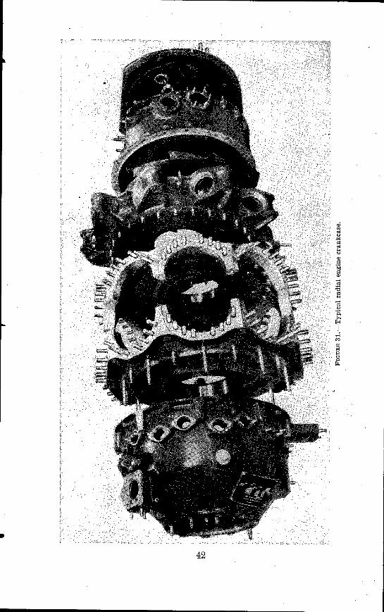
power section, the mounting section, the supercharger section, and the accessory section. Figure 31 illustrates the various sections of a radial engine crankcase. Late type main or power sections are constructed of steel to further increase strength.
(1) The nose or front section usually incorporates the valve tappets and their guides, the crankshaft or propeller shaft thrust bearing, the propeller control valve, the drilled oil passages for the lubrication of the various operating parts, and in the geared engine, it encloses the reduction gears in addition to the cam mechanism.
(2) The main or power section, to which the cylinders are attached, is usually made of two symmetrical forgings joined in the plane of the center line of the cylinders by long through bolts. The main crankshaft bearings and the cam drive gear assembly are located in this section.
(3) The mounting section is located immediately behind the main section, incorporating the mounting lugs which provide for the attach- ment of the engine to the mounting ring. This section usually forms the front wall of the supercharger diffuser and distributor chamber and carries the tangential ports of the intake pipes leading to the cylinders.
(4) The supercharger section usually carries the supercharger diffuser plate, carburetor, fuel pump, gun synchronizers, and vacuum pump. It also acts as a housing for the accessory drive gears.
(5) The accessory section usually forms the rear crankcase cover to which most of the engine accessories, such as magnetos, generator, and starter are attached.
c. V-type engine crankcases are made up of two parts, consisting of an upper and lower half. The upper half forms the foundation upon which the parts of the engine are assembled and is constructed of light aluminum alloy, forged or die-cast for rigidity and strength. This section incorporates the crankshaft main bearings and incloses the crankshaft, thrust bearings, connecting rods, and, in geared engines, the reduction gears. The lower section, or oil pan, bolts to the upper half to form an oiltight compartment around the crankshaft and connecting-rod assembly.
d. The increase in the number of accessories attached to the engine has led to the development of a remote engine driven gear box. This gear box may be placed in a convenient position close to the engine and used to drive the many accessories which now appear to "clutter up" the rear of an engine installation.
28. Intake manifolds.—a. Intake manifolds and induction pipes are the parts of an engine which distribute the fuel and air charge
424577°—42 6 41
42

AIRCRAFT ENGINES
TM 1-405 28
to the various cylinders and provide a chamber for the fuel to vapor- ize and thoroughly mix with the air before being admitted into the cylinder. The design and number of intake manifolds or pipes naturally depends upon the type of the engine and the number of cylinders to which they are attached.
b. In radial engines, individual intake pipes connect the super- charger or blower section chamber to the intake ports of the cylinders and are constructed of a thin light alloy or sheet steel. By reference to the intake pipe (fig. 32®), it will be noted that the cylinder end is shaped in a symmetrical curve to provide a minimum of restriction to the flow of the incoming fuel charge. The lower end of the intake pipe is inserted into the tangential ports of the blower section and
° d " " B a B G D a to a" a a to a to „ a
O s$tr&>^ 5 C
1 ! 1 I " < 1 t
1 1 a ■ :
! 1 i
1 1 i C
I 1 i « :> < J 0
/ \
} < » c ? c
® - © FIGUEE 32.—:Eadial engine intake pipe and liquid-cooled engine manifold.
made gastight by the use of a rubber ring and a locking nut. This arrangement permits the intake pipe to move with the elongation and contraction of the cylinder, thus preventing distortion.
c. Manifolds are employed to conduct and distribute the mixture charge in V-type and in-line engines. These manifolds are made of cast aluminum alloy and conduct the fuel-air mixture from the car- buretor or supercharger outlet to the cylinders, where it is divided at each intake port. Two or more manifolds are generally used, each cast to accommodate groups of three cylinders as illustrated in figure 32®. Suitable gaskets and hose connections are employed to assure gastight connections. A jacket may be provided in some manifold installations to allow either the coolant or the lubricating oil to cir-
43

TM 1-405 28-29 AIR CORPS
culate around the intake passages. The heat given off in either case aids in the vaporization of the fuel charge.
29. Exhaust manifolds.—a. The primary function of the ex- haust manifold is to conduct, with a minimum of back pressure, exhaust gases, hot carbon flakes, etc., into the slipstream with mini-
type exhaust manifold installation.
mum hazard to the airplane and pilot. Some of its additional func- tions may be the supplying of heat to the induction system and to a cockpit or cabin heater for use in cold weather.
b. The simplest exhaust piping is made up of a short steel tube extending slightly rearward from each exhaust port. This minimizes
44

AIRCRAFT ENGINES
TM 1-405 29
back pressure and exhaust valve temperatures. The disadvantages in the use of individual exhaust stacks are—
(1) More exhaust noise. (2) Elimination of means for transmitting heat to the induction
system and other auxiliary devices. (3) Increased fire hazard. (4) Danger of sudden cooling of exhaust valves during side slip
maneuvers of the airplane. (5) Failure to conduct injurious gases away from the airplane.
FIGURE 34.—Rear-type exhaust manifold.
c. In some radial engines, stainless steel exhaust manifolds of the tangential type are used (figs. 33 and 34). These types are generally known as collector rings, and collect and conduct exhaust gases wher- ever desired. These collector rings may be installed on the front side of the cylinders or on the rear side, as desired.
(1) The front type consists of a large collector ring installed over the nose section of the engine into which the exhaust gases of each cylinder are expelled at a tangent through individual connecting pipes. An expanding joint is provided in each pipe to allow for expansion differences without distortion. A large common outlet
45

TM 1-405 29-30 AIR CORPS
pipe, streamlined downward and backward, forms an integral part of the ring. The front type of manifolding lends itself readily to supplying heat to the induction system, cockpit, and is also adaptable tor use with an external exhaust driven supercharger installation
(2) Minor variations from the front-type ring exhaust manifold permit installation on the rear of an engine, usually with the outlet opening extending out through the side or bottom of the engine cowling. This location permits better cooling of the cylinders especially on high-powered engines. '
d. In V-type aircraft engines two stainless steel exhaust manifolds are used, one attached to each cylinder bank. Individual openings attached to each exhaust port lead the exhaust gases to a common outlet chamber which becomes larger in diameter as it tapers back and out toward its outlet opening (fig. 35). For the installation of an exhaust-driven supercharger the two outlet openings of the exhaust
2 EXHAUST VALVES
PER CYLINDER
FIGURE 35.—V-type engine exhaust manifold.
manifolds on a V-type engine are joined together and the exhaust gases directed through one common outlet into the supercharger nozzle box.
30. Coolant pumps.—a. Coolant pumps for liquid-cooled engines are of the centrifugal type. This type is used in preference to the plunger, vane, and gear types, because it has high capacity at low pressure. The centrifugal-type pump consists of a light alloy flanged circular plate, an impeller, and a light alloy casting or housing. The impeller is installed with a minimum working clearance for obvious reasons It is driven by the crankshaft through suitable gearing and forces the inflowing liquid outward through the tangential housing openings and attached manifolds into the cooling jackets. Figure 36 illustrates a typical centrifugal-type pump.
b. Packing glands are provided in the pump housing surrounding the driveshaft to prevent leakage of the coolant. This packing is manufactured of a suitable material and impregnated with graphite
46

AIRCRAFT ENGINES TM 1-405
30-31
to minimize wear on the driveshaft. The packing gland nut is ad- justable to take up wear of the packing material whenever required.
c. The capacity of the coolant pump depends upon its size and the speed at which the impeller is driven, usually 100 gallons per minute being the minimum rate.
31. Oil pumps and relief valves.—a. All aircraft engine lubri- cating systems require oil pumps to circulate oil under pressure to the various working parts and to scavenge the engine of surplus oil. For this purpose the gear type of pump (fig. 37) is generally used. In this type a multiple of steel gears are contained in one housing for a pressure pump and either one or two scavenging pumps. When
A. Impeller shaft. B. Guide bushing. C. Packing gland nut. D. Driveshaft end.
E. Impeller bushing. F. Impeller housing. G. Impeller body. H.. End thrust plate.
FIGÜKE 36.—Centrifugal-type coolant pump.
only one scavenging pump is used it must incorporate larger sized gears than those in the pressure pump to insure positive scavenging of the oil from the crankcase. Each pump or set of gears is assembled in independent recesses of the unit but on the same shaft, in order to permit one shaft to drive both pumps simultaneously. The pumps are driven by the crankshaft through suitable gearing.
b. To regulate the pressure of the oil circulated to the various working parts of the engine, a relief valve is incorporated on the discharge side of the pressure pump. In some instances provisions are made to install the relief valve in the oil-pump assembly. As a general rule, oil pressure relief valves may be regulated by increas-
47

TM 1-405 31-32 AIR CORPS
ing or decreasing the tension of a spring acting on a valve. This is accomplished by turning an adjustable screw provided in the as- sembly. Figure 38 shows an oil pump in which provisions are made to install a relief valve. In instances where oil pressure is required to operate hydraulic-controlled propellers, the relief valve is usually located at the end of the main pressure line. This insures positive pressure to the propeller before the relief valve functions.
c. In some engines provisions are made to drive an additional oil pump for the operation of hydraulic systems. This pump is of the gear type similar in construction to a conventional oil-pressure pump.
32. Fuel pumps.—a. Most conventional aircraft fuel systems in- corporate a fuel pump driven directly or indirectly by the engine crankshaft. Early type engines used the two-gear type pump similar in construction to the oil-pressure shown in figure 37. However due to the low viscosity of gasoline and the high column of fuel in long
DRIVEN GEAR
^DISCHARGE
FIGURE 37.—Typical gear pump.
fuel lines which must be delivered at positive pressure and high ca- pacity to the carburetor, the vaned-type pump (fig. 39) is considered more efficient than other types at the same operating speed. Fuel pumps are usually driven at crankshaft speed.
b. The vaned-type pump consists of a cylindrical aluminum body in which a steel liner has been inserted to minimize wear. The sliding vanes, sleeve, and shaft assembly fit into the steel liner eccentrically so that when rotated they cause a suction at the intake side or port of the pump body. Provision is made at the drive end of the pump to prevent fuel leakage around the shaft by an adjustable lock screw and cork gland, or a special automatic spring take-up metal disk which does not require the use of packing material. In case of leakage, a drain is incorporated in the pump whereby the fuel may be directed overboard.
48

AIRCRAFT ENGINES TM 1-405
32
a
a
ft
49

TM 1-405 32-33 AIR CORPS
c. Most modern fuel pump assemblies incorporate a relief and/or bypass valve. With this assembly, the use of a material number of plumbing units is eliminated. The fuel pump drive and mounting flange is usually installed in the rear, or accessory drive section, how- ever, in some V-type engines it is located in the vertical camshaft driveshaft housing. The pump may be mounted directly to the mounting flange or it may be conveniently located in the aircraft and operated by a remote flexible driveshaft assembly.
33. Vacuum pumps.—a. Due to the increased use of gyro instru- ments which require suction or subatmospheric pressure in their operation and to the unreliability and inadequate capacity of venturi tubes, an engine-driven vacuum pump has been designed to obtain uniform and adequate pressures. By the use of a suitable cock, either
DRAIN
FIGURE 39.—Vaned-type fuel pump.
the venturies or the vacuum pump may be used independently as a safety factor in case trouble develops in either system.
i. The conventional vacuum pump (fig. 40) is of the vaned type. It consists of a cylindrical aluminum body in which a steel liner is inserted to minimize wear. The sliding vanes, sleeve, and shaft as- sembly fit into the steel liner eccentrically in such a manner that when rotated they cause a suction at the intake side, or port, and a pressure at the exhaust side, or port, of the pump body. It will be noted from the above description that a vaned-type vacuum pump is almost identical with a vaned-type fuel pump, except in external appearance. An adjustable spring loaded relief valve is incorporated in the suction line between the pump and gyro instruments and may be regulated to furnish the proper amount of subatmospheric pressure
50

AIRCRAFT ENGINES
TM 1-405 33
to the various units. A restricted orifice in the pump body is con- nected to the pressure side of the engine oiling system to furnish proper lubrication.
G. In order to provide a satisfactory means of exhausting the waste oil from the vacuum pump, either one of four methods may be em- ployed. In some cases the waste oil is conducted into the slipstream
FIGUKE 40.—Vaned-type vacuum pump and relief valve.
through suitable piping with the air exhaust from the pump. An- other method is to lead the waste oil and air to the carburetor air intake, and a third is to connect the pump exhaust line to the exhaust manifold of the engine where the exhaust pressure is less than 1 inch Hg. In the fourth method, the oil and air exhaust passes into an oil separator which permits the air to flow out into the atmosphere and the oil to flow back into the tank or engine.
51

TM 1-405 33-35 AIR CORPS
d. The various types of engines used and the availability of a suit- able drive for the vacuum pump necessitate several designs of mount- ing flanges and pump driveshaft ends. On V-type engines, the pump is usually mounted on the magneto driveshaft housing especially de- signed for this purpose. All late-type radial engines incorporate a special mount built on the rear crankcase section for installing and driving the pump. All types of vaned pumps are designed to operate in either direction, provided the intake and exhaust ports are properly connected.
34. Engine accessories.—The engine accessories, such as starters, generators, carburetors, magnetos, distributors, spark plugs, and ig- nition wiring, are of such importance as to require a separate manual for their description and operation.
SECTION IV
REPAIR PRINCIPLES Paragraph
General 35 Preparation of engine for disassembly 36 Disassembly 37 Clearance specifications 38 Cylinder inspection and repair :_: 39 Piston inspection and repair 40 Manifolds and pipes '. 41 Assembly 42 Checking valve timing 43 Checking ignition timing 44
35. General.—a. The information in this section pertaining to engine repair principles is limited to the repairs which may be accom- plished in the field, provided the necessary tools and equipment are available. Although the following instructions are given with the assumption that the engine has been removed from the aircraft for "top" overhaul, the procedure is equally applicable to a large number of repairs which can be accomplished with the engine installed in the aircraft.
b. The various major units of aircraft engines are very much the same in general design and construction, the principal difference being in their size and arrangement. In view of this similarity in construc- tion, the same general procedure of repair may be followed for all types with few exceptions. The most important items that are nec- essary in connection with the repair of a particular type of engine are a complete set of special tools and the engine specifications. For
52

TM 1-405 AIRCRAFT ENGINES 35-38
detailed information on repairs reference must" be made to technical publications on the equipment involved.
36. Preparation of engine for disassembly.—Mount the engine oh a suitable revolving stand that will permit the rotation of the engine to any desirable position. As the various units and parts are removed from the engine they should be placed on a bench or portable stand for cleaning and inspection. Small parts such as bolts, nuts, washers, etc., should be placed in suitable containers where they will not be misplaced. Cleaning of engine parts may be accomplished by suitable cleaning solutions and compressed air. In either case the cleaning should be done in some part of the shop where the dirt and refuse may be readily disposed of, preferably in a separate room. A mixture of carbon tetrachloride and naphtha (50 percent by volume of each) makes an excellent noninflammable cleaning solution.
37. Disassembly.—Due to the difference in construction of the various types of engines, the order and procedure of disassembly will vary somewhat for each type; therefore only general instructions that may be applied to all types will be given here.
a. Usually all accessories should be removed first. This equip- ment, on the average engine, consists of the magnetos, carburetors, generator, starter, spark plugs, etc. Removal of these items elimi- nates possible breakage during disassembly. Next, remove all cyl- inder attachments. This usually includes the push rods, manifolds, ignition wiring, fuel, oil and coolant lines, etc.
b. Dismount the cylinder assemblies with valve mechanism intact. Extreme care should be exercised in removing cylinders to prevent damage to pistons and piston rings. If possible, have the piston at the top of the stroke when the cylinder is removed and disassemble the piston from the connecting rods immediately upon removal of the cylinder. When dismounting the cylinders from radial-type en- gines, the cylinder in which the master connecting rod is located should be removed last, thus preventing its free movement during disassembly of the remaining cylinders. Screw drivers or similar tools should never be used as a pry under cylinder flanges as such will mar the mating surfaces or spring the cylinder hold-down flanges.
c. During disassembly of the various units, all marks and fits should be carefully observed so as to facilitate assembly and adjustment.
38. Clearance specifications.—The correct clearance to be al- lowed between the various moving parts of an engine depends upon the material of which the part is fabricated, the stresses to which it is subjected, and the temperature at which it operates. The manu-
53

TM 1-405 38-39 AIR CORPS
facturer uses certain clearance specifications for factory assembly and adjustment of each type of engine; these specifications have been determined through careful experimentation, and should be used by the mechanic during repair. The clearance tables are usually given in four columns of dimensions, for example, minimum clear- ance for new parts, desired clearance for new parts, maximum clear- ance for new parts, and maximum clearance allowable due to wear. In addition, each dimension is usually followed by the letter "L" or "T," the letter "L" indicating a loose fit and the letter "T" indi- cating a tight fit. For example, the dimension 0.002-inch L indicates that the I. D. of the outer mating surface is 0.002 inch larger than the O. D. of the inner mating surface, and the dimension. 0.002-inch T indicates the I. D. of the outer mating surface is 0.002 inch smaller than the O. D. of the inner mating surface.
39. Cylinder inspection and repair.—a. The cylinder barrels should be inspected for scores, scratches, and wear. If scores, scratches, or excessive wear are found in any one cylinder, it should be replaced.
b. In the case of liquid-cooled engines, the cylinder jacket should be tested under pressure with air or water.
c. Check the valve springs for general condition and tension. In some instances valve springs may lose their tension due to overheat- ing and fatigue; therefore, they should be carefully checked with a valve-spring tester.
d. Check the valves for condition of the stem and face. If the valve stem is worn or the valve face contains pits and scratches, the valve should be replaced. (For various fits and tolerances, consult hand book on individual engines.) Check the valve seat for condi- tion. If it contains pits or scratches, it should be resurfaced with a special reseating tool. After resurfacing the valve seat, the valve should be carefully lapped or ground into the seat. Use a medium grade grinding compound for this purpose. After the valves have been lapped in, they should be installed in the cylinder and tested for proper seating by pouring gasoline into the combustion chamber. Any irregularity in the seat or valve 'face will be indicated by the leaking of gasoline into the valve ports.
e. Check the valve stem guides for general condition and wear. In the event that new valve stem guides are installed, the valve seats should be refaced after installation of the guides.
/. The remaining valve mechanism should be given a thorough inspection, and care must be taken to see that all parts are marked
54

TM 1-405 AIRCRAFT ENGINES 39-40
before removal, so that they may be replaced exactly as removed. A systematic check up should'be made in the following order:
(1) Rocker arms—for correct side clearance, fit of shaft, condition of roller, and condition of ball socket.
(2) Push rods—for condition of ball ends and alinement (care must be taken to avoid reversing the push rods on reassembly).
(3) Cam followers—for proper functioning, fit in guide, and con- dition of ball socket.
(4) Overhead lubrication system—for freeness from restrictions and particles of foreign matter.
(5) The above procedure applies particularly to radial engine in- stallations and must be modified to include a check of the overhead camshafts, etc., on most liquid-cooled engines. An indication of failure in any of the units calls for immediate replacement.
40. Piston inspection and repair.—a. Remove all carbon de- posits from the piston by means of an approved carbon solvent.
.&., After the piston is thoroughly cleaned, it should be checked for scores, scratches, and wear. Light scores and scratches are not seri- ous and may be dressed down by an oilstone. Deep scores and scratches are cause for replacement of the piston. Wear on one side of the piston skirt usually indicates bent or twisted connecting rods and, if excessive, necessitates replacement of the piston as well as the rod. A new piston should weigh within a specified amount of the old piston when replacement is made.
c. Piston rings should be checked for tension, clearance, and wear. Rings are removed from the cylinder when checking them for tension. Those with less than 14-inch gap, or which require less than 5 pounds tension to close the gap, are weak and ordinarily should be replaced. Rings should fit snug but not tight in the piston groove. The gap is checked by inserting the ring near the lower end of the cylinder barrel and measuring with a thickness gage, being careful to keep the ring perfectly square in the cylinder bore. In fitting new rings, if the gap is less than specified, it may be increased by dressing down the butt ends with a small, smooth file. If the gap is more than specified by the table of limits, the ring should not be used.
d. Check the piston pins as well as the piston-pin bushings for wear. The piston pin should be a hand push fit in the piston at room temperature. Its fit in the connecting rod depends entirely upon the type of piston pin used. Piston pins in 0.005 and 0.010 inch oversize are usually held in stock by the engine manufacturer for replacement purposes. When oversize pins are used, the piston and connecting-rod bushings must be reamed to size.'
55

TM 1-405 41-43 AIR CORPS
41. Manifolds and pipes.—a. Intake pipes of radial engines should be carefully inspected for cracks and dents, especially at their attaching ends. Intake manifold assemblies should be checked for älinement at their cylinder attachment flanges with the use of a surface plate. If out of alinement, they may be lapped or dressed down on a lapping plate.
b. Check the attaching flanges of exhaust manifolds for warpage and cracks. Cracked tubing may be welded; however, if the flanges are warped, the unit must be replaced.
42. Assembly.—In view of the difference in construction of the various types of engines, the order and general procedure of assem- bly will be somewhat different for each type. However, if the order and procedure of disassembly were carefully observed, no difficulty should be experienced during assembly. The following points apply generally to all types:
a. Keep all parts scrupulously clean. b. Lubricate all bearings, bushings, shafts, etc., during assembly. c. Keplace all gaskets, packings, etc. d. Safety all bolts, nuts, etc., with new cotter pins or safety wire. e. Assemble all parts and units in the reverse order of disassembly
and according to the manufacturer's marks. /. Never use parts that are defective or worn beyond the limits
given in the table of clearance specifications. 43. Checking valve timing.—a. If the engine parts were assem-
bled according to the manufacturer's marks, the valve timing should be correct; however, in view of the importance of correct valve tim- ing and the possibility of errors during engine assembly, a complete and thorough check of the valve timing after assembly is advisable. The exact procedure for timing each type of engine differs some- what; therefore only instructions that may be generally applied to all types will be given here.
b. The following valve-timing specifications with respect to the crankshaft position should be checked:
(1) Intake valve opening position. (2) Intake valve closing position. (3) Exhaust valve opening position. (4) Exhaust valve closing position. c. All valve-timing specifications are given in degrees of crank-
shaft travel and usually refer to the position of the crankpin, before or after top and bottom center. In tables of specifications the following abbreviations are generally used:
(1) Top center (TC).
56

TM 1-405 AIRCRAFT ENGINES" 43-44
(2) Bottom center (BC). (3) Before top center (BTC). (4) After top center (ATC). (5) Before bottom center (BBC). (6) After bottom center (ABC). d. The following is the general procedure for checking the valve
timing of the average engine: (1) Adjust the valve tappets to the timing clearance specified by
the manufacturer. (This usually differs from cold clearance and the two should not be confused.) .The clearances are set with the valves fully closed and with the piston on top center following the com- pression stroke.
(2) Install the timing disk or fixture on the engine and a-top center indicator in the front spark-plug hole of No. 1 cylinder.
(3) Rotate the propeller shaft slowly in the proper direction of rotation until No. 1 piston is at exact top center.
(4) Install the timing fixture pointer so that it registers exactly with the top center mark on the timing disk.
(5) Place a 0.0015-inch thickness gage blade between the exhaust valve rocker arm and the valve stem in No. 1 cylinder and continue to turn the crankshaft until the thickness gage blade no longer has clearance, indicating that the exhaust valve in No. 1 cylinder is just at the point of opening.
(6) If the engine is in time the pointer will register with the point on the timing disk marked "exhaust valve opens." Should this mark not correspond to the indication of the pointer, the engine must be retimed.
(7) As a further check, the 0.0015-inch thickness gage blade should next be inserted under the intake valve rocker arm of No. 1 cylinder and the above operation repeated. At the point that the thickness gage no longer has clearance, the pointer should indicate "intake- valve opens" on the timing fixture. A slight variation between the timing of the exhaust and intake valves is allowable, due to manu- facturing tolerances and normal wear. Any excessive variation would, however, indicate an error in timing or mechanical trouble in the valve operating mechanism.
(8) In the event that the timing does not correspond to the specifi- cations, it may be changed by resetting the timing gear or serrations.
(9) After the valve timing has been checked all valve tappets should be adjusted to the specified cold clearance.
44. Checking1 ignition timing.—The exact procedure of check- ing the ignition timing varies somewhat for each type of engine;
57

TM 1-405 44-45 AIR CORPS
therefore, only general instructions will be given here. The following general procedure may be applied to the average engine:
«. Install the timing fixture on the propeller shaft as when checking the valve timing.
b. Adjust the breaker points to the correct clearance (pivot type). c. Connect a test light circuit in series with ignition breaker points
or place a very thin gage between the breaker points (spark fully advanced).
d. Turn the propeller shaft in the direction of rotation until No. 1 piston starts up on the compression stroke, then proceed very slowly until the breaker points just break (this will be indicated by the light going out or the gage between the breaker points being released).
e. The pointer should now indicate the specified number of degrees before top center on the timing disk for the firing of No. 1 cylinder. Also the marks on the magneto distributor segment should line up with corresponding marks on the magneto housing indicating that the rotor is lined up with No. 1 distributor segment.
/. Where two magnetos or a double magneto is employed on an engine requiring "staggered" ignition timing, each unit or distributor must be checked separately. In case the ignition units are "synchro- nized" the timing of both systems may be accomplished at the same time.
SECTION V
ENGINE LUBEICATION Paragraph
Lubrication requirements '. 45 Radial engine lubrication 46 In-line and V-type engine lubrication 47
45. Lubrication requirements.—a. When one dry metallic sur- face is moved over another, a high resistance or friction is encoun- tered which results in the generation of heat and excessive wear. If a layer of greasy substance or lubricant is placed between the two metallic surfaces, the wear on the metal is practically eliminated, and heat is reduced to a minimum. Friction between metallic surfaces can be classified as sliding, rolling, or ball-bearing friction. Sliding friction such as encountered in the majority of engines in main and connecting-rod bearings, requires more complete lubrication than rolling friction encountered in roller bearings. Of the three, ball- bearing friction requires the least amount of lubricant for proper lubrication.
58

TM 1-405 , AIRCRAFT ENGINES 45
ö. In aircraft engines, the lubrication system is designed to meet the problems of high temperatures, high bearing stresses, and proper functioning in all flight attitudes of the aircraft, except the inverted.
G. The high temperature of the various engine parts tends to thin out the lubricant (lower its viscosity) which decreases its effective- ness in overcoming metallic friction; therefore, provisions must be made to cool the oil externally. The cooled oil, on reentering the lubrication system of the engine, materially assists in reducing the high temperatures of the various parts, particularly the bearings.
d. The high bearing loads, especially in connecting rods, result in metallic friction which is reduced to a minimum by allowing sufficient clearance between the bearing surfaces to accommodate a heavy film of oil. This film of oil introduces a 'cushioning effect which considerably reduces the strains of shock loading.
e. The oil pressure pump and its distributing lines and passages circulate the oil under pressure to the various working parts of the engine as long as the oil is supplied to the inlet side of the oil pump. The externalpart of the oiling system furnishes this supply under all conditions of engine operation except inverted flight. The scavenging system must thoroughly drain the crankcase of surplus oil. This is accomplished by the use of various drains and sumps incorporated in the lowest section of the engine. In prolonged steep dives, steep climbs, vertical banks, and inverted flight, there is a probability that the scavenging system will cease to function, result- ing in surplus oil accumulating in the crankcase. Under such con- ditions, provisions must be made in the design and location of the crankcase oil breathers to prevent this surplus oil from flowing out of the engine.
/. The system that supplies oil under pressure to the operating parts and completely scavenges the crankcase of surplus oil is known as the force or pressure dry sump type of lubricating system. Al- though the pressure part of the system is more or less independent of the scavenging part, both parts must function properly to insure proper lubrication.
g. The pressure part of the ;system consists of the pressure pump, pressure relief valve, and distributing pipes or passages leading to the various parts to be lubricated. In addition to those parts to be lubricated under pressure, there are numerous other parts, such as pistons, cylinder walls, valve mechanism,' accessory drive gears, etc., which are lubricated by the splash or spray of oil agitated by the revolving crankshaft and connecting rods. An oil pressure relief valve is installed in some part of the pressure system and is adjusted
59

TM 1-405 45-46 AIR CORPS
to maintain a specific oil pressure, shunting the surplus oil back into the scavenging system, or to the inlet side of the pressure pump. In instances where hydraulically controlled propellers are used, two oil pressure relief valves, or a compensating relief valve, may be em- ployed to insure positive pressure to the propeller shaft. An oil- pressure gage connection is also installed in some part of the pressure system for connecting a line leading to the oil pressure indicator. A suitable oil screen or strainer is incorporated in the system to re- move foreign particles, sediment, etc., from the oil before it reaches the bearing surfaces.
h. The scavenging part of the system consists of a scavenging pump, drain sumps, screens, and the necessary oil return lines. One or more drain sumps are required to collect the surplus oil from the engine crankcase and are located in the lowest section of the engine. Screens are incorporated in the sumps to prevent foreign particles, sediment, etc., from circulating through the system. The oil return lines or passages connect the sump chambers to the intake side of the scaveng- ing pump which returns the oil to the supply tank for recirculation to the pressure part of the system.
i. For complete details of the lubrication system employed in a spe- cific engine, reference must be made to the lubrication chart in the technical publication for the engine involved.
46. Radial engine lubrication.—The circulation of oil through a typical radial-type engine is shown in figure 41.
a. In the pressure part of the system, the oil enters the pump (A), which forces it through the screen or strainer (B), to the rear and front crankshaft journals. The oil is forced into the drilled passages in the rear crankshaft journal which lead to the crankpin, master con- necting-rod bearing, and short-rod knuckle pins. One or more lines or passages branch from the rear crankshaft journal and lead the oil to the various rear section drive shaft bearings (C). The line branching off the front crankshaft, journal leads the oil under pressure to a con- trol valve (D), by which a hydraulic, controllable pitch propeller may be operated by the engine oil pressure directed to the connection (E). The oil pressure relief valve (F) is adjusted to obtain the desired pres- sure, in the system, shunting surplus oil into the scavenging system, or to the inlet side of the pressure pump. The dotted arrows designate oil forced out at various points in the pressure system which lubricate, by splash or spray, such parts as pistons, rings, cylinder walls, acces- sory drive gears, etc., before draining into the scavenging system sumps.
60

AIRCRAFT ENGINES
TM 1-405 46-47
b. In the scavenging system, an oil sump (G), located in the lowest section of the crankcase. collects all the surplus oil drained from the pressure system. The screen (H), located in the sump, prevents for- eign particles from restricting the flow of oil returning to the scaveng- ing pump and is accessible for periodical removal and cleaning. The scavenging pump (I) removes the oil from the sump and forces it back into the external oiling system for recirculation. - c. In connection with the lubrication, system, a crankcase breather (J) is installed at some point on the upper part of the crankcase to
^////^/ wmw^
r' SCAVENGING SYSTEM
\PRESSURE SYSTEM
A. Pressure pump. B. Strainer.
" C. Accessary drive shaft. D. Propeller control valve. E. Propeller oil connection.
F. Pressure relief valve. G. Sump. H. Screen. I. Scavenging pump. J. Breather.
FIGURE 41.—Typical radial engine lubricating system.
relieve internal pressure resulting from high temperatures and high- speed piston operation. Provisions are made in the construction of the breather to permit escape of the pressure without loss of oil, usually by the use of internal baffles. In some breathers a gravity- operated valve remains open in normal attitudes of the engine and closes when the engine is inverted. This is done to prevent oil from flowing out of the breather in inverted flight.
47. In-line and V-type engine lubrication.—The circulation of oil through a typical in-line or V-type engine is illustrated in figure 42.
61

TM 1-405 47-48 AIR, CORPS
a. In the pressure part of the system the oil enters the pump (A), which forces it through the screen or strainer (B) and distributing pipe to each of the crankshaft journals. From the rear crankshaft journal the oil is forced to the hollow camshaft (C), furnishing lubri- cation to the overhead valve mechanism. From the front crankshaft journal a pressure line leads through an oil-control valve (D) to a connection (E) for operating a hydraulic, controllable pitch propeller. In geared engines, a pressure line leads to the propeller-shaft reduc- tion gear. The oil-pressure relief valve (F) is adjusted to obtain the desired pressure in the system, shunting surplus oil to the intake side of the pressure pump. The oil which is forced into the crankshaft journals is thrown by centrifugal force to the crankpins and connect- ing-rod bearings. The dotted arrows designate oil thrown out at various points in the pressure system, which lubricates by splash or spray such parts as pistons, rings, cylinder walls, valves, tappets, accessory drive gears, and bearings before draining into the scaveng- ing sumps.
b. In the scavenging system two scavenging pumps (I) are shown, one of which drains the front engine sump (G), through the screen (H), and the other drains the oil from the rear sump (G') and forces it back into the external supply for recirculation.
c. The oil breather (J) is usually located at the front end of the engine and extends a certain distance into the crankcase to prevent loss of oil through the breather at certain attitudes of engine operation. Several baffles may be incorporated in the breather which aid in pre- venting escape of oil mist under all operating conditions.
SECTION VI
ENGINE COOLING Paragraph
General 48 Fundamentals of air cooling 49 Fundamentals of liquid cooling : 50 Coolants 51 Cooling systems 52
48. General.—The power developed by an engine is directly pro- portional to the heat of combustion; however, it is essential that the operating temperatures of the engine are maintained within safe limits to prevent preignition, valve warpage, spark-plug failure, and other attendant disadvantages of a hot engine. The heat loss, charged directly to cooling, is approximately 30 percent of the total heat gen- erated and cannot be appreciably reduced without decreasing the re-
62

AIRCRAFT ENGINES TM 1-405
48
<§4J
<KV Q
63

TM 1-405 48-49 AIR CORPS
liability of engine operation. Therefore, in order to utilize heat as power the engine must be adequately cooled. This is accomplished either by air or liquid cooling.
49. Fundamentals of air cooling.—a. In cooling aircraft en- gines by air, the following factors are of importance:
(1) The rate of cooling is directly proportional to the area of the surface exposed to the cooling medium.
(2) The rate of cooling is dependent upon the thermal conductivity of the metal used, especially in the cylinder heads.
(3) The rate of cooling is dependent upon the volume of metal or cross section, consistent with conductivity, surface, and the mass flow of air. Cylinder head fins taper from a comparatively heavy base cross section to a very thin cross section area at the tip.
(4) The rate of cooling varies almost directly with the mass of air flow over the heated surfaces. The use of pressure baffles around the cylinders increases the cooling efficiency in flight but often decreases it during ground operation.
(5) The rate of cooling varies directly with the difference in tem- perature between the metal surfaces exposed and the cooling air. Hence, a higher rate of cooling is obtained in cold weather than in hot weather.
b. As previously stated, air-cooled cylinders are made up of steel barrels and light alloy heads heavily finned for strength and adequate cooling. Improvement of the rate of cooling by means of fins can be readily observed by referring to figure 43. Exposed fin areas have been increased from approximately 600 square inches to 2,800 square inches per cylinder to adequately care for the tremendous increase in combustion temperatures obtained with the use of improved fuels. Special attention is given to the most effective distribution of the fins to provide uniform cooling over the entire combustion chamber, in- cluding the spark-plug bosses and exhaust valve seat.
c. Air deflectors or pressure baffles are used extensively in high performance aircraft engines to obtain a more effective use of the cooling air and to increase the velocity of the air flow over the cooling fins. Figure 44 illustrates a typical pressure baffle system for a twin- row engine. A disadvantage in the use of pressure baffles is that inadequate cooling during ground operation may result in engine overheating; therefore, ground operation must be restricted to a minimum before take-off and flight.
d. In addition to the heat dissipated from the engine cylinder fins, a certain amount is conducted to other parts of the engine and radi-

AIRCRAFT ENGINES
TM 1-405 49
©
65

TM 1-405 49-50 AIR CORPS
ated into the cooling medium. The circulating oil also absorbs heat which is dissipated through the oil cooler.
e. The cowling surrounding an engine installed in an airplanet must be considered as a vital element in the cooling system, its design being dependent upon the design of the aircraft in which the engine is installed.
/. The operating temperature of an air-cooled engine is measured by a temperature indicator and thermocouple attached to the barrel or cylinder head of the hottest running cylinder, which is usually the one carrying the master connecting rod.
REAR CYLINDER BARREL
FRONT CYLINDER BARREL
COOLING FINS
111 II It Ml IIII! AIR FLOW
FIGURE 44.—Typical pressure baffles for a twin-row engine.
50. Fundamentals of liquid cooling.—a. In cooling aircraft engines with liquid, the following factors are of importance:
(1) The rate of cooling is directly proportional to the amount of coolant brought into contact with the propeller slipstream. The large amount of surface required is obtained through the use of a satisfactory radiator made up of numerous tubes, arranged so as to produce a minimum of frontal resistance. Other surfaces, such as the cylinder jacket, manifolds, etc., assist in the rate of cooling.
(2) The rate of cooling is dependent upon the thermal conduc- tivity of the metal used, especially in the construction of the radiator tubes or cores.
(3) The rate of cooling is dependent on the volume of metal or cross section in the radiator tubes or cores, consistent with their con-
66

AIRCRAFT ENGINES TM 1-405
50
ductivity, their surface area, and the mass flow of air around them. In high output liquid-cooled engines, this factor becomes very im- portant in the design of efficient radiators.
(4) The rate of cooling varies almost directly with the mass of air flow through the radiator. Provisions are usually made to con- trol the air flow through the radiator by the use of shutters, either manually or automatically operated.
FIGURE 45.—Liquid-cooled cylinder jacket.
(5) The rate of cooling varies with the difference in temperature between the coolant and the cooling air, resulting in a higher heat transfer in cold weather.
(6) The rate of cooling varies with the rate of liquid flow through the system, up to a' certain critical: velocity. Above this critical velpcity. turbulent flow pr surface scouring occurs, and the rate of liquid flow does not increase the cooling effect, but does increase operating pressures in the system.
b. As previously stated, liquid-cooled cylinders are made up of a bank of several steel barrels inserted in a light alloy casting or jacket.
- 6T

TM 1-405 50-51 AIR CORPS
This jacket (fig. 45) provides the recesses through which the cooling liquid is circulated by the pump (fig. 46), absorbing heat from the cylinder barrels and transferring it to the radiator for dissipation.
G. The use of ethylene glycol in its pure state or by dilution in water is preferred over water aJone, as its high boiling point (350° F., 177° C.) will preclude evaporation of coolant liquid at normal engine operat- ing temperatures which may be considerably higher (250° F., 121° C.) than when using water alone. This permits the use of a com- paratively small radiator, resulting in a low weight per horsepower and a minimum of head resistance.
/mp*/l*r
FIGURE 46.—Coolant pump.
d. As in air-cooled engines, a certain amount of heat is conducted from the cylinders to other parts of the engine and radiated into the air stream. The circulating oil also absorbs heat from the engine and dissipates it in circulating through the oil cooler.
e. The operating temperature of a liquid-cooled engine is meas- ured by a thermometer installed in the coolant discharge outlet line to the radiator.
51. Coolants.—a. There are a large number of liquids which may be used as coolants for internal-combustion engines; however, in order to meet the desired requirements in liquid-cooled aircraft engines, this number is restricted to water and ethylene glycol.
68

TM 1-405 AIRCRAFT ENGINES 51
(1) Water is universally used as an engine coolant largely because of its availability and high specific heat value. The disadvantages in its use in aircraft engines, compared to ethylene glycol, are its high rate of evaporation or low boiling point, its high freezing "point accompanied by the fact that it expands when frozen, resulting in probable damage to the cooling system, and its impurity.
(a) Its comparatively low boiling point of 212° F. (100° C), necessitates the use of a large radiator in the cooling system to main- tain an operating temperature below 190° F. (88° C), and a com- paratively large amount of liquid. This results in a high head resistance and a high weight per horsepower in aircraft engines.
(b) Its high freezing point of 32° F. (0° C), presents a problem in maintaining the water above that temperature when the power plant is inoperative in cold weather.
(c) Inasmuch as most of the water used in engine-cooling systems comes from wells, rivers, and lakes, even though filtered, it is some- what impure, and frequent draining and flushing of the system is necessary.
(2) Ethylene glycol (Prestone) is a chemical substance made up of ethylene oxide (CH2)20 combined with H20 (water) to the satu- ration point, forming a molecular structure C2H602. Ethylene is obtained from petroleum oil or by the destructive distillation of car- bonaceous matter. The term glycol was designated by the chemist wh© originally combined the structure C2H602. Ethylene glycol is a colorless liquid having practically no odor, is nonpoisonous, mod- erately noninflammable, nontoxic, noncorrosive, and nonelectrolytic in action. The advantages of ethylene glycol over water as a coolant are its high boiling point and low freezing point, accompanied by the fact that when freezing it contracts instead of expands. An addi- tional advantage is its comparative purity. The disadvantages are low specific heat, resulting in higher engine temperatures with a slight loss in power, and its limited availability.
(a) The high boiling point of ethylene glycol, which is in excess of 350° F. (177° C), permits the use of a smaller radiator than if water is used. Obviously, the smaller radiator reduces head resist- ance and weight per horsepower.
(b) Its low freezing point of approximately 0° F. ( — 18° C), and the fact that it does not freeze solid until a temperature of — 48° F. (—45° C.) is reached, protects the cooling system during extremely cold weather. However, no attempt should be made to start and operate an aircraft engine when the ethylene glycol is at a tempera- ture below 0° F., as it will not circulate properly while in the form
69

TM 1-405 51 AIR CORPS
of slush. When it is known in advance that it will be exposed to temperatures below 0° F., for an extended period of time, it should be drained from the cooling system while hot and heated before it is replaced in the system.
(c) Although ethylene glycol is considered pure when first placed in the cooling system, its natural tendency to loosen rust, scale, etc., from certain parts, requires frequent draining and thorough straining before it is returned to the system.
(d) In military service, ethylene glycol conforming to current specifications is used as a coolant in aircraft engines.
b. In engines using water as a coolant, it is advisable in cold weather to add some kind of a soluble substance to prevent it from freezing and damaging the cooling system. Ethylene glycol, glyc- erin, and alcohol are satisfactory for this purpose. Of these, ethy- lene glycol is considered the best. It is soluble in water in any proportion and when mixed with water, it freezes in the form of slush instead of solid.
(1) The prospective temperatures to be encountered govern the amount of ethylene glycol to be used with water. The percent, by volume, required to prevent freezing of the solution at different tem- peratures is indicated in figure 47. Ethylene glycol does not evapo- rate at the usual operating temperatures; therefore, under ordinary conditions only the evaporated water need be replaced. In the event that some of the solution has leaked out of the system through joints, connections, etc., it will be necessary to add more ethylene glycol; the amount may be determined by a thermohydrometer or a standard specific gravity hydrometer test.
(a) The thermohydrometer is of similar construction and is used in the same manner as the ordinary battery hydrometer. It has a small thermometer enclosed within a floating bulb and the readings are made from two scales and a chart enclosed within the hydrometer instead of one scale as with the ordinary hydrometer. This type of hydrometer gives a direct reading of the temperature at which the solution will freeze and is preferred to the specific gravity hydrom- eter which gives only the percentage of ethylene glycol in the solution. The specific gravity reading should be obtained with the solution at 60° F., and in addition, requires the use of a conversion table to find the actual temperature at which the solution will freeze. Detailed instructions for reading the various hydrometers are usually included in their containers.
(i) Ethylene glycol expands, when heated, considerably more than water at the same temperature; therefore, care must be exercised to
70

TM 1-405 AIRCRAFT ENGINES 51
provide the proper amount of expansion space in the cooling system when it is used as an antifreeze solution. This is usually accom- plished by draining off one gallon of the solution after filling the system to its normal water capacity.
(2) Glycerin is used to some extent as an antifreeze in water- cooled engines. Its use in aircraft engine cooling systems is not
BOILING POINT
•C. F. ma n ■an«
FREEZING POINT
"C. *F.
4.4 40
- I.I 30
- 6.7 20
-I2.2 10
_I7.8 0
-23.3 - 10
-28.9 - 20
-34.4 - 30
_40. -40
-45.5 - 50
-51. -60
193.9 380
187.7 3 70
182.2 360
176.7 350
171.1 340
165 6 33 0
/ /
/
/
/
/ 160.0 320
154.4 310
148.9 30 0
143.3 290
137.8 28 0
132.2 270
126.7 260
12 1 1 250
1 1
1 I 1
i /
/ ,/ /
/ /
/ • 115 6 24 O
/ / 1
110.0 23 0
104 4 220 \ J \. / 98.9 2 10
: ( 5 10 20 30 4 ETHYLENE GLYC
0 50 6 OL PERCE
0 70 80 90 l( NT BY VOLUME
-BOILING POIN1
)0
r ' T
Pi 3UEE 47.— Ethyl ene glycol
71
antif reeze solu tions.

TM 1-405 51-52 AIR CORPS
desirable, due to its gumming characteristics and difficulties encoun- tered in preventing it from leaking out of the system.
(3) Alcohol is used extensively as an antifreeze in automotive engines, largely because it is inexpensive. The commercial alcohols furnished for this purpose are known as denatured alcohols, made up principally of ethyl (grain) alcohol and methyl (wood) alcohol. The greater the percentage of ethyl alcohol in the mixture, the better it is for antifreeze purposes, as ethyl alcohol has a higher boiling point than methyl alcohol, therefore less is lost by evaporation. Due to the high operating temperatures of aircraft engines, the use of denatured alcohol as an antifreeze is prohibited.
52. Cooling' systems.—Although the cooling fundamentals in- volved in the design and construction of an aircraft engine are highly efficient, the problem confronting the aircraft designer is in maintain- ing high efficiency with a minimum of head resistance. This problem applies to both air-cooled and liquid-cooled aircraft engines.
a. In air-cooled engine installations high cooling efficiency is main- tained by mounting streamlined ring type cowling around the outside circumference of the cylinders. The cooling efficiency of a well-de- signed cowling ring varies somewhat with the speed of the aircraft or velocity of the air flow. As a general rule, cowling designed for high efficiency at high air velocities is somewhat inefficient at low air velocities, particularly when operating the engine on the ground. To overcome this difficulty, controllable flaps may be incorporated in the trailing edge of the ring cowling or by the development of a suitable low-pressure system. ,
(1) Some air-cooled engine installations in low-performance air- planes incorporate a cowling over the front crankcase section, provid- ing a means of control by which the airflow can be circulated in, and around, the crankcase in warm weather, and partially closed off in cold weather.
(2) Present «air-cooling systems are designed to maintain proper engine temperatures at maximum permissible power and rpm in level flight or at the best climbing speed when the ground temperature is 100° F. (38° C.) or löwer. The cylinder-head temperature should not exceed 280° C. and the base temperature should not exceed 165° C. for safe engine operation. Normal head values range from 160° C. to 200° C. and normal base values from 120° C. to 140° C. Consult oper- ating instructions for specific values of individual engines.
(3) The head temperature may be measured with a thermocouple mounted at the spark plug as illustrated in figure 48. ' This type of thermocouple is usually installed in place of the standard spark-plug
72

TM 1-405 AIRCRAFT ENGINES 52
gasket in the master connecting-rod cylinder. Where an attachable spark-plug shield is used, the thermocouple gasket is installed between the shield and cylinder head. The two thermocouple wires are of iron and iron constantin, each wire properly designated for correct installa- tion on the cylinder temperature indicator in the aircraft cockpit. In lieu of the spark-plug type of thermocouple, the two thermocouple wires may be imbedded in the master-rod cylinder head or base flange and connected to the indicator in the same manner.
(4) Inasmuch as the cooling of the air-cooled engine is assisted by the circulating oil, an abnormal cylinder temperature indicator rise may be caused by an abnormal "oil in" temperature rise due to lack of oil, improper oil cooling, or an oil line restriction, hence the neces- sity for stopping or "throttling down" the engine when overheating is indicated.
i. While the cooling system of an air-cooled engine is more or less self-contained, such is not the case in a liquid-cooled aircraft engine.
BLACK wee TO pos/r/re COPPER GASKET-^ fi/WK O/v GAGE
ycCLOWHI#£TO//£GAW£/
FIGURE 48.—Spark-plug type of thermocouple.
In addition to the cooling principles involved in the design and con- struction of liquid-cooled engines, there are a number of auxiliary units installed in the aircraft which form an integral part of the complete cooling system. These units include the radiator, auxiliary expansion tank, and the necessary plumbing connecting them to the engine. A thermometer and gage are incorporated in the system to indicate the operating temperature of the coolant. A controllable radiator shutter assembly and one or more centrifuge tanks may also be included. ,
(1) The radiator performs the function of maintaining the tem- perature of the coolant within safe limits with a minimum of head resistance. The cowling installed around the radiator constitutes an important item, as its design controls the volume of air directed through the radiator. Satisfactory design and construction permits a maximum amount of cooling with a minimum amount of weight. The radiator core is usually constructed of copper and the tanks or headers of brass. . • ■ ' •
73
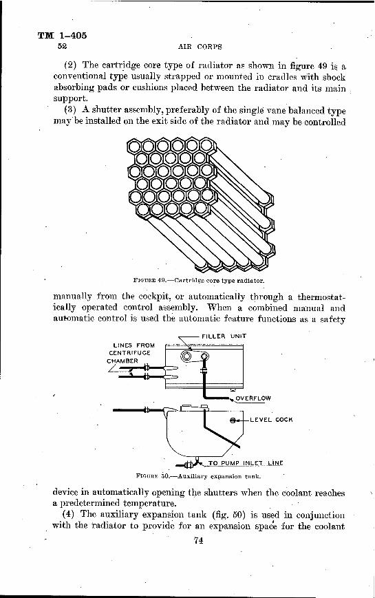
TM 1-405 52 AIR CORPS
(2) The cartridge core type of radiator as shown in figure 49 is a conventional type usually strapped or mounted in cradles with shock absorbing pads or cushions placed between the radiator and its main support.
(3) A shutter assembly, preferably of the single vane balanced type may be installed on the exit side of the radiator and may be controlled
FIGURE 49.—Cartridge core type radiator.
manually from the cockpit, or automatically through a thermostat- ically operated control assembly. When a combined manual and automatic control is used the automatic feature functions as a safety
FILLER UNIT
LINES FROM CENTRIFUGE
CHAMBER
OVERFLOW
LEVEL COCK
.^tj)-^* TO PUMP INLET LINE
FIGURE 50.—Auxiliary expansion tank.
device in automatically opening the shutters when the coolant reaches a predetermined temperature.
(4) The auxiliary expansion tank (fig. 50) is used in conjunction with the radiator to provide for an expansion space for the coolant
74

AIRCRAFT ENGINES TM 1-405
52
in the system as it becomes heated. It is installed at the highest point in the system and serves as the filler unit through which the entire system is serviced with coolant. The bottom of the expansion tank is connected to the top of the radiator through suitable plumbing. The capacity of the expansion tank and its outlet pipe to the radiator is 10 percent of the total capacity of the system plus 1 gallon. For example, if the total capacity of a cooling system is 10 gallons, the expansion tank and line to the radiator holds 2 gallons of that amount. A unique feature of the expansion tank is the installation of two valves in the filler unit (fig. 51). The large poppet valve operates and relieves internal pressure as the circulating coolant is heated
POPPfT VMV£ OPENS WHEN PPESSUPE BECOMES EXCESSIVE. AS COOCA/VT BECOMES HOT
BAU CHECK VAL V£ AD/i/TS A/P ///TO ST5TEA7PEUEV/A/G PAPT/ÄL VACUUM CPE ATED ßrSUDOEA' COOLING OF COOLANT
A/P VENT
FIGURE 51.—Expansion tank filler unit.
and the small ball check valve permits admission of outside air into the system as the coolant temperature decreases. The automatic oper- ation of both of these valves maintains a constant differential air pressure in the expansion tank.
(5) The plumbing in a liquid-cooled system includes piping, flexi- ble hose connections, and necessary drain plugs. The piping is usually of brass or aluminum alloy tubing with a minimum wall thickness of 0.050 inch under the hose clamps. Aluminum alloy tubing is pro- tected from possible corrosion by an anodic treatment. Rubber hose is used in flexible connections and is deterioration resistant. ^7hen installed, the hose should not have less than 14-inch or more than one pipe diameter exposed to the coolant. Standard hose clamps are
75

TM 1-405 52 AIR CORPS
used to hold the connections in place and prevent leakage of the cool- ant. In some instances it may be necessary to install additional clamps to prevent the leakage of ethylene glycol when it is used as a coolant. A large size drain plug is located in the lowest part of the system for draining the coolant.
(a) Water piping is marked with a white band near each union and on each side of every flexible connection. Ethylene glycol piping is marked with a black band bordered by two white bands.
(&) A thermometer well (fig. 52) is incorporated in the coolant outlet line from the engine to the radiator. The thermometer bulb is installed in the well and the outlet temperature of the coolant is indicated on the thermometer gage in the aircraft cockpit.
(6) In liquid-cooled systems, where leakage of the exhaust gases through cylinder gaskets or joints may occur, centrifuge chambers (fig. 53) are installed in the engine discharge lines to the radiator.
FIGURE 52.—Thermometer well.
The turbulence of the coolant in circulating through the centrifuge chamber separates the gas vapors from the coolant and directs the vapors through the chamber vent line to the expansion tank. If gases were permitted to accumulate in the coolant circulating lines there would be a probability of gas-pocket formation which would interfere with proper circulation of the liquid. A general conception of the unit arrangement in a cooling system, with the exception of a radiator shutter, may be obtained by reference to figure 54.
(7) In the operation of water-cooled power plants care must be exercised to prevent water temperature from exceeding 85° C. Where ethylene glycol coolant is utilized it must not exceed 150° C. With an adequate supply of coolant and proper functioning of the system, excessive temperatures may be prevented by opening the shutter control if this unit is installed. In case no shutter control is installed, high coolant temperatures may be reduced by retarding the throttle or by enriching the mixture with the mixture control.
76
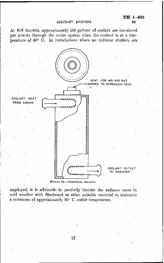
AIRCRAFT ENGINES TM 1-405
52
At full throttle, approximately 100 gallons of coolant are circulated per minute through the entire system when the coolant is at a tem- perature of 60° C. In installations where jio radiator shutters are
COOLANT INLET
FROM ENGINE
VENT FOR AIR AND'GAS
VAPORS TO EXPANSION TANK
COOLANT OUTLET TO RADIATOR
FIGURE 53.—Centrifuge chamber.
employed, it is advisable to partially blanket the radiator cores in cold weather with fiberboard or other suitable material to maintain a minimum of approximately 60° C. outlet temperature.
77

TM 1-405 52 AIR CORPS
78

TM 1-405
INDEX Paragraph Page
Accessories, engine.. 34 52 Air-cooling fundamentals, engine 49 64 Assembly:
Crankcase 27 40 Crankshaft 24 32 Engines 1 42 56 Piston _ i 22 29
Bearings 25 37 Blowers, internal ■ 26 38
Calculation of horsepower 8 10 Checking:
Ignition timing 44 57 Valve timing 43 56
Classification of engine types _ 9-17 13 Clearance specifications, engine parts ' 38 53 Compression of charge 7 8 Connecting rods 23 32 Construction and description of engine units ; 18-34 21 Conversion of heat into mechanical energy 2 2 Coolant pumps., ...: 30 46 Coolants . 51 68 Cooling:
Engine . 48-52 62 Systems. .■ 52 72
Crankcase assemblies i 27 40 Crankshaft assemblies..: 27 40 Cycles, engine 3 2
Four-stroke, principle 4 3 Two-stroke, principle 5 7
Cylinder: , Inspection 39 54 Numbers ;_1 16 16 Repair '. 39; 54-
Cylinders. . 19 23
Diesel engine principle. L__ 6 7 Disassembly of engines._ 1 36, 37 53 Double V-engine 12 14
Engine: Accessories . 34 52 Cooling 48-52 62 Cycles 3 2 Diesel, principle — 6 7
79

TM 1-405 INDEX
Engine—Continued. Lubrication: Paragraph Page
In-line 47 61 Radial ; _ 46 60 V-type 47 61
Types: Double V___ 12 14 Fan 12 14 Fiat 14 15 In-line . 10 14 Opposed . 14 15 Radial 15 16 V-type . . 11 14 X-type 13 14
Units 18-34 21
Fan type engines , 12 14 Firing orders, engine ; 17 17 Flat type engines 14 15 Four-stroke cycle principle 4 3 Fuel pumps 32 48 Fundamentals of cooling: ■
Air . 49 64 Liquid 50 66
Horsepower calculations 8 10
Ignition timing 44 57 In-line type engines 10 14 Internal blowers or superchargers . 26 38 Internal-combustion engine principles 1-8 1 Inspection:
Cylinder 39 54 Piston 40 55
Intake manifold 28 41
Liquid cooling fundamentals 50 66 Lubrication:
Radial engines 46 60 Requirements 45 58
Manifolds 41 56 Exhaust : 29 44 Intake •__. 28 41
Numbers, cylinder j 16 16
Oil pumps 31 47 Opposed type engines :_ 14 15 Order of firing, cylinders 17 17
Piston: Assemblies 22 29 Inspection 40 55 Repair 40 55
Pipes . 41 56
80

TM 1-405 INDEX
t Paragraph Page
Preparation of engine for disassembly : 36 53 Principles, repair 35-44 52 Pumps:
Coolant 30 46 Fuel. 32 48 Oil__ 31 47 Vacuum 33 50
Radial type engines ^ 15 16 Lubrication 46 60
Relief valves 31 47 Repair:
Cylinder ■— - 39 54 Principles,., -'-- 35-44 52
Requirements, lubrication 45 58 Rods, connecting 23 32
Specifications, clearance, engine parts 38 53 Springs, valve 20 25 . Superchargers 26 38
Timing: Valve___- — 43 56
: Ignition 44 57 Two-stroke cycle principle 5 7
Vacuum pumps 33 50 Valves - 20 ,25
Mechanism : -- 21 26 Relief..-. 31 47 Springs .-- 20 25 Timing 43 56 V-type engines . H .14
X-type engines 13 14 [A. G. 062.11 (10-3-41).]
BY ORDER OF THE SECRETARY OF WAR : G.C.MARSHALL,
Chief of Staff.
OFFICIAL: > E. S. ADAMS,
Major General, The Adjutant General.
DISTRIBUTION: B and H 1, 17 (5); El, 17 (10); Bn 1, 9, 17 (5); IBn 1 (10);
IC9, 17 (5). (For explanation of symbols see FM 21-6.)
81 H.S. GOVERNMENT PRINTING OFFICE: 1942
For sale by the Superintendent of Documents - Washington, D. C.