*tm 9-6115-647-14&p technical manual · pdf filetm 9-6115-647-14&p safety steps to...
TRANSCRIPT

*TM 9-6115-647-14&P
TECHNICAL MANUAL
OPERATOR, UNIT, DIRECT SUPPORT ANDGENERAL SUPPORT MAINTENANCE MANUAL
(INCLUDING REPAIR PARTS ANDSPECIAL TOOLS LISTS)
POWER UNITPU-789/M (NSN 6115-01-208-9827)
MEP-114A 30 KW 400 HZ GENERATOR SETM353 2-WHEEL, 2-TIRE, MODIFIED
TRAILER
*This manual supersedes Chapter 17 of TM 5-6115-594-14&P, dated 25 September 1984.
Approved for public release; distribution is unlimited.
HEADQUARTERS, DEPARTMENT OF THE ARMY
11 AUGUST 1990

TM 9-6115-647-14&P
SAFETY STEPS TO FOLLOW IF SOMEONE IS THE VICTIM OF ELECTRICAL SHOCK
DO NOT TRY TO PULL OR GRAB THE INDIVIDUAL
IF POSSIBLE, TURN OFF THE ELECTRICAL POWER
IF YOU CANNOT TURN OFF THE ELECTRICAL POWER, PULL, PUSH, OR LIFT THEPERSON TO SAFETY USING A DRY WOODEN POLE OR A DRY ROPE OR SOME OTHERINSULATING MATERIAL
SEND FOR HELP AS SOON AS POSSIBLE
AFTER THE INJURED PERSON IS FREE OF CONTACT WITH THE SOURCE OFELECTRICAL SHOCK, MOVE THE PERSON A SHORT DISTANCE AWAY ANDIMMEDIATELY START ARTIFICIAL RESUSCITATION
a

TM 9-6115-647-14&P
WARNING
All specific cautions and warnings contained in this manual shall be strictly adhered to. Otherwise, severeinjury, death and/or damage to the equipment may result.
HIGH VOLTAGE
is produced when this power unit is in operation.
DEATH
or severe burns may result if personnel fall to observe safety precautions. Do not operate this power unit untilthe ground terminal stud has been connected to a suitable ground. Disconnect the battery ground cable on thegenerator set before removing and installing components on the engine or in the electrical control panelsystem. Remove all rings, watches, and other jewelry when performing maintenance on this equipment. Loosefitting clothing should be secured to prevent it catching moving parts. Do not attempt to service or otherwisemake any adjustments, connections or reconnections of wires or cables until generator set is shut down andcompletely de-energized.
DANGEROUS GASES
Batteries generate explosive gas during charging therefore, utilize extreme caution. Do not smoke, or use openflame in the vicinity of the generator set when servicing batteries.
Exhaust discharge contains noxious and deadly fumes. Do not operate power unit generator sets in enclosedareas unless exhaust discharge is properly vented to the outside.
To avoid sparking between filler nozzle and fuel tank, always maintain metal to metal contact between fillernozzle and fuel tank when filling generator set fuel tank.
Do not smoke or use open flame in the vicinity of the power unit while refueling generator sets.
LIQUIDS UNDER HIGH PRESSURE
are generated as a result of operation of the power unit generator set. Do not expose any part of the body to ahigh pressure leak in the fuel injection system.
NOISE
Operating noise level of the generator set can cause hearing damage. Ear protectors, as recommended by themedical or safety officer, must be worn when working near this power unit.
WARNING
Clean parts in a well-ventilated area. Avoid inhalation of solvent fumes and prolonged exposure of skin tocleaning solvent. Wash exposed skin thoroughly. Dry cleaning solvent (PD-680) used to clean parts ispotentially dangerous to personnel and property. Do not use near open flame or excessive heat. Flash point ofsolvent is 100°F to 138°F (380C to 590C).
b

TM 9-6115-647-14&PC1
CHANGE HEADQUARTERSDEPARTMENT OF THE ARMY
NO. 1 WASHINGTON, D.C., 14 March 1994
Operator, Unit, Direct Support andGeneral Support Maintenance Manual
(Including Repair Parts andSpecial Tools Lists)
POWER UNITPU-789/M (NSN 6115-01-208-9827)
MEP-114A 30 KW 400 HZ GENERATOR SETM353 2-WHEEL, 2-TIRE, MODIFIED
TRAILER
DISTRIBUTION STATEMENT A: Approved for public release; distribution is unlimited.
TM 9-6115-647-14&P, 1 August 1990, is changed as follows:
1. Remove and insert pages as indicated below. New or changed text material is indicated by a vertical barin the margin. An illustration change is indicated by a miniature pointing hand.
Remove pages Insert pages
iii and iv iii and iv1-1 through 1-4 1-1 through 1-5/(1-6 blank)3-5 and 3-6 3-5 and 3-64-3 through 4-6 4-3 through 4-64-19 through 4-24 4-19 through 4-244-31 through 4-36 4-31 through 4-364-45 and 4-46 4-45 and 4-464-49 through 4-52 4-49 through 4-53/(4-54 blank)5-1 through 5-8 5-1 through 5-85-19 and 5-20 5-19 and 5-205-25 and 5-26 5-25 and 5-26D-7 through (D-15 blank)/D-16 D-7 through D-16D-27 through D-29/(D-30 blank) D-27 through D-29/(D-30 blank)D-35 Through D-42 D-35 through D-42D-49 through D-52 D-49 through 0-52(D-55 blank)/D-56 through D-64 (D-55 blank)/D-56 through D-64D-67 and D-68 D-67 and D-68D-71 through D-82 D-71 through D-83/(D-84 blank)
2. Retain this sheet in front of manual for reference purposes.


*TM 9-6115-647-14&P
HEADQUARTERSTECHNICAL MANUAL DEPARTMENT OF THE ARMYNO. 9-6115-647-14&P WASHINGTON, D.C., 11 August 1990
Operator, Unit, Direct Support and General Support Maintenance Manual(Including Repair Parts and Special Tools Lists)
forPOWER UNIT, PU-789/M(NSN 6115-01-208-9827)
MEP-114A 30 KW 400 HZ GENERATOR SETM353 2-WHEEL, 2-TIRE, MODIFIED TRAILER
Approved for public release; distribution is unlimited.
TABLE OF CONTENTSPage
CHAPTER 1. INTRODUCTION
Section I. General. .................................................................................................. 1-1Section II. Description and Data............................................................................... 1-2
CHAPTER 2. OPERATING INSTRUCTIONS
Section I. Operating Procedures. ............................................................................ 2-1Section II. Operation of Auxiliary Equipment............................................................ 2-2Section III. Operation Under Unusual Conditions....................................................... 2-2
CHAPTER 3. OPERATOR/CREW MAINTENANCE INSTRUCTIONS
Section I. Consumable Operating and Maintenance Supplies.................................. 3-1Section II. Lubrication Instructions............................................................................ 3-1Section III. Preventive Maintenance Checks and Services (PMCS) .......................... 3-1Section IV. Troubleshooting ...................................................................................... 3-24Section V. Operator/Crew Maintenance.................................................................... 3-25
CHAPTER 4. UNIT MAINTENANCE
Section I. Service Upon Receipt of Equipment........................................................ 4-1Section II. Movement to a New Worksite ................................................................. 4-6Section III. Repair Parts, Special Tools, Test, Measurement and
Diagnostic Equipment (TMDE) .............................................................. 4-6Section IV. Lubrication Instructions............................................................................ 4-7Section V. Preventive Maintenance Checks and Services........................................ 4-7Section VI. Troubleshooting. ..................................................................................... 4-12Section VII. Radio Interference Suppression .............................................................. 4-19Section VIII. Maintenance of Power Unit Electrical System ......................................... 4-19Section IX. Maintenance of Power Unit Trailer .......................................................... 4-45
*This manual supersedes Chapter 17 of TM 5-6115-594-14&P dated 25 September 1984.
i

TM 9-6115-647-14&P
PageCHAPTER 5. DIRECT SUPPORT AND GENERAL SUPPORT
MAINTENANCE INSTRUCTIONS
Section I. Introduction ............................................................................................. 5-1Section II. Generator Set ......................................................................................... 5-1Section III. Maintenance of Power Unit Electrical System ......................................... 5-5Section IV. Fuel System Maintenance....................................................................... 5-18Section V. Maintenance of Power Unit Trailer .......................................................... 5-22Section VI. Power Unit Marking ................................................................................. 5-27
CHAPTER 6. TEST AND INSPECTION AFTER REPAIR
Section I. General Requirements ............................................................................ 6-1Section II. Inspection................................................................................................ 6-1Section III. Operational Tests.................................................................................... 6-1
APPENDIX A. REFERENCES........................................................................................ A-1
APPENDIX B. COMPONENTS OF END ITEM AND BASIC ISSUE ITEMS LISTS......... B-1
APPENDIX C. MAINTENANCE ALLOCATION CHART.................................................. C-1
APPENDIX D. UNIT, DIRECT SUPPORT, GENERAL SUPPORT AND DEPOTMAINTENANCE REPAIR PARTS AND SPECIAL TOOLS LIST........ D-1
ii

TM 9-6115-647-14&P
LIST OF ILLUSTRATIONS
Figure Title Page
1-1 Power Unit, Curbside Front, Three-Quarter View..................................................1-31-2 Power Unit, Roadside Rear, Three-Quarter View..................................................1-31-3 Interconnected Power Units..................................................................................1-44-1 Unpacking Power Unit ..........................................................................................4-24-2 Installing Power Unit ............................................................................................4-44-3 Adapter Plate Assembly Wiring Diagram..............................................................4-224-4 Adapter Plate Assembly Replacement .................................................................4-244-5 Power/Control Cable and Auxiliary Cable Wiring Diagram....................................4-254-6 Control Cable Wiring Diagram..............................................................................4-264-7 P3 Power/Control Cable Wiring Diagram..............................................................4-274-8 P3 Power/Control Cable Replacement .................................................................4-294-9 Power Distribution Unit Wiring Diagram ...............................................................4-324-10 J1 Wiring Harness Replacement ..........................................................................4-344-11 J6 Wiring Harness Replacement ..........................................................................4-354-12 J10 Wiring Harness Replacement ........................................................................4-374-13 P8 Wiring Harness Replacement..........................................................................4-384-14 P9 Wiring Harness Replacement . ..................................................................4-394-15 Control Relay/Diodes Wiring Harness Replacement.............................................4-404-16 PDU Relay Replacement .....................................................................................4-424-17 Power Distribution Unit.........................................................................................4-434-18 Front Step and Support Replacement ..................................................................4-464-19 Rear Step Replacement .......................................................................................4-474-20 Walkway and Fender Bracket Replacement .........................................................4-494-21 Tailgate and Hinge Block Replacement................................................................4-514-22 Reflector Replacement.........................................................................................4-524-23 Data and Identification Plate Replacement...........................................................4-534-23.1 Data Plate Replacement. .....................................................................................4-535-1 Generator Set Replacement.................................................................................5-45-2 Adapter Plate Assembly Repair............................................................................5-65-3 Adapter Plate Assembly Wiring Diagram..............................................................5-75-4 P4, P7 Low Fuel Cable Repair ............................................................................5-95-5 Power Distribution Unit Repair..............................................................................5-135-6 PDU Contactor Replacement ...............................................................................5-155-7 PDU Contactor Wiring Diagram ...........................................................................5-165-8 PDU Diode Replacement .....................................................................................5-175-9 PDU Terminal Board Replacement ......................................................................5-185-10 Fuel Tank and Fuel Line Replacement .................................................................5-205-11 Fuel Tank Repair .................................................................................................5-225-12 Storage Tray and Cover Repair and Replacement ...............................................5-245-13 Generator Set Support Repair and Replacement..................................................5-265-14 Trailer Marking.....................................................................................................5-275-15 Power Distribution Unit Marking ...........................................................................5-28
Change 1 iii

TM 9-6115-647-14&P
LIST OF ILLUSTRATIONS (cont)
Figure Title Page
Components of End Item......................................................................................B-2Basic Issue Items .................................................................................................B-3
D-1 Generator Set ......................................................................................................D-7D-2 Adapter Plate Assembly .......................................................................................D-10D-3 Power/Control and Auxiliary Cables .....................................................................D-16D-4 Control Cable .......................................................................................................D-18D-5 P3 Power/Control Cable .. .............................................D-20D-6 P4, P7 Fuel Cable................................................................................................D-24D-7 P12, J11 Wiring Harness......................................................................................D-26D-8 Ground Wire Assemblies .....................................................................................D-28D-9 Power Distribution Unit.........................................................................................D-31D-10 J6 Wiring Harness................................................................................................D-38D-11 J1 Wiring Harness................................................................................................D-40D-12 J10 Wiring Harness .............................................................................................D-42D-13 P8 and P9 Wiring Harness ...................................................................................D-44D-14 Control Relay/Diodes Wiring Harness ..................................................................D-46D-15 Fuel System.........................................................................................................D-49D-16 Trailer Assembly ..................................................................................................D-56D-17 Storage Tray ........................................................................................................D-62D-18 Front Steps ..........................................................................................................D-64D-19 Rear Steps ...........................................................................................................D-66D-20 Walkways.............................................................................................................D-68D-21 Tailgate................................................................................................................D-70D-22 Data Plates and Reflectors...................................................................................D-72D-23 Power Source Jumper Cable................................................................................D-74
LIST OF TABLES
Number Title Page
3-1 Consumable Operating and Maintenance Supplies ..............................................3-13-2 Operator/Crew Preventive Maintenance Checks and Services (PMCS)................3-44-1 Unit Preventive Maintenance Checks and Services (PMCS) ................................4-94-2 Troubleshooting ..................................................................................................4-134-3 Fabrication of Power Source Jumper Cable .........................................................4-44
iv Change 1

TM 9-6115647-14&P
CHAPTER 1
INTRODUCTION
Section I. GENERAL
1-1. Scope. This manual is for your use in operating and maintaining the Power Unit PU-789/M. The PU-789/M is a mobile power unit used to supply power to the Patriot Information Coordination Central (ICC) and itsAntenna Mast Group (AMG) or to the Communications Relay Group (CRG) and its Antenna Mast Group. Inaddition to operating instructions and operator, unit, direct support and general support maintenanceprocedures, this manual contains a Repair Parts and Special Tools List for the power unit.
1-2. Maintenance Forms and Records. Maintenance forms and records used by Army personnel areprescribed by DA Pam 738-750.
1-3. Reporting of Errors. Reporting of errors and omissions and recommendations for improvement of thispublication by the individual user is encouraged Reports should be submitted on a DA Form 2028 directly toCommander, U S Army Aviation and Troop Command, ATTN: AMSAT-I-MP, 4300 Goodfellow Boulevard, St.Louis, MO 63120-1798.
1-4. Reporting Equipment Improvement Recommendations (EIR). EIR's will be prepared using SF 368Product Quality Deficiency Report. Instructions for preparing EIR's are provided in DA Pam 738-750, TheArmy Maintenance Management System. EIR's should be mailed directly to Commander, U.S. Army Aviationand Troop Command, ATTN: AMSAT-I-MDS, 4300 Goodfellow Boulevard, St. Louis, MO 63120-1798.
1-5. Levels of Maintenance Accomplishment. Army users shall refer to the Maintenance Allocation Chart(MAC) for tasks and levels of maintenance to be performed.
1-6. Destruction of Army Materiel. Destruction of Army Materiel to prevent enemy use shall be inaccordance with TM 750-244-3.
1-7. Administrative Storage.
a. Placement of equipment in administrative storage should be for short periods of time when ashortage of maintenance effort exists. Items should be in mission readiness within 24 hours or within the timefactors as determined by the directing authority. During the storage period appropriate maintenance recordswill be kept.
b. Army equipment placed in administrative storage will have preventive maintenance performed Inaccordance with the PMCS tables before storage. When equipment is removed from storage, PMCS will beperformed to assure operational readiness.
c. Storage site selection. Inside storage is preferred for items selected for administrative storage. Ifinside storage is not available, trucks, vans, conex containers and other containers may be used.
1-8. Preparation for Shipment and Storage. Refer to TB 740-97-2.
Change 1 1-1

TM 9-6115-647-14&P
Section II. DESCRIPTION AND DATA
1-9. Description. Power Unit PU-789/M (figures 1-1 and 1-2) is made up of one Tactical Precise GeneratorSet, DOD model MEP-114A, mounted on a modified M353 trailer. The generator set is a liquid-cooled dieselengine-driven unit with a load capacity of 30 KW at 400 HZ. The trailer is a two-wheeled, two-tire unit with a 3-½ -ton carrying capacity. The modifications to the basic trailer provide stowage for the accessories and allequipment necessary for mobile operation, work platforms and access steps for the operator and maintenancepersonnel, and a 93-gallon fuel tank. A low fuel sensor is activated and supplies a low fuel signal to the PatriotInformation Coordination Central (ICC) and the Communications Relay Group (CRG) when the fuel level dropsbelow 13.5 gallons (51.1 liters). The PU-789/M provides a generator on-line signal to the ICC/CRG andprovides for power disconnect from the ICC/CRG. Since the PU-789/M is exclusively used for supplying powerto the ICC and its Antenna Mast Group (AMG) or to the CRG and its Antenna Mast Group, the power unit isequipped with a Patriot application kit. This kit consists of a power distribution unit (PDU) mounted on thetrailer, an adapter plate assembly mounted on the generator set to provide an interconnection point forgenerator set and PDU cabling, and the related cables and wiring harnesses. In the field, two PU-789/M powerunits are used interconnected as shown in figure 1-3, where one power unit is designated the primary powersource and the second unit serves as a standby unit in the field configuration, the PDU provides aninterconnection point for the primary and standby power units and the ICC or CRG, allowing either unit tosupply 120/208 VAC 400 HZ power to the equipment.
1-10. Tabulated Data. The tabulated data provides operator and unit level personnel with the dimensions andweights for Power Unit PU-789/M. These specifications are computed from the combined dimensions andweights of the generator set and trailer as modified for use with the power unit. Specifications of the individualcomponents can be found in their respective technical publications. For additional information concerningGenerator Set DOD Model MEP-114A, refer to TM 5-6115-465-12, -24P and -34. For additional information onthe M353 trailer, refer to TM 9-2330-247-14&P. The tabulated data also includes the location and content of alldata plates unique to the power unit.
a. Identification and Instruction Plates.
(1) Identification plate.
(a) Location. This plate is located on the front curbside trailer frame.
(b) Content.
US ARMYELECTRIC POWER UNITPU-789/MLG 188 19 IN./W 96 00 IN./HGT 84.50 IN.NSN 6115-01-208-9827PART NO. 97403-13227E5850MFD BY:CONTRACT NO.DATE MFD:SERIAL NO.DRY WT 6800 LBSREGISTRATION NO. VB01FY
1-2 Change 1

TM 9-6115-647-14&P
Figure 1-1. Power Unit, Curbside Front, Three-Quarter View.
Figure 1-2. Power Unit, Roadside Rear, Three Quarter View.
Change 1 1-3

TM 9-6115-647-14&P
Figure 1-3. Interconnected Power Units.
1-4 Change 1

TM 9-6115-647-14&P
(2) Instruction plate.
(a) Location. This plate is located near the ground stud on the front, curbside corner of the trailer body.
(b) Content
GROUND
(3) Handling data plate.
(a) Location. This plate is located on the front curbside corner of the trailer body.
(b) Content. This plate contains a diagram of the power unit and gives dimensions, shipping weight, cubage and pinpoints lifting locations.
b. Tabulated Data for Power Unit.
Overall Length 188.19 inches (478 centimeters)Overall Width 95 ½ inches (242 6 centimeters)Overall Height 84.5 inches (214 6 centimeters)Net Weight (empty) T.B.S.Net Weight (filled) T.B.S.Shipping Weight 6800 pounds (3087.2 kilograms)Volume 884 cubic feet (24.75 cubic meters)
1-11. Differences Between Models. There are no differences between models.
Change 1 1-5/(1-6 blank)

TM 9-6115-647-14&P
CHAPTER 2
OPERATING INSTRUCTIONS
Section I. OPERATING PROCEDURES
2-1. Power Unit Operating Procedures. The typical mission for any mobile power generating equipment canbe described in three steps or phases. In the first phase, the power unit is towed to the worksite and installedby unit level technicians (paragraph 4-2). In the second phase of the mission, the operator starts the generatorset, runs it to power a system or equipment, and eventually shuts it down. In the final phase, the power unit isdismantled, packed up and either moved to a new worksite or returned to standby status (paragraph 4-3). Thisfinal phase is also accomplished by unit level technicians.
a. Generator Set Operating Procedures.
WARNING
Do not operate power unit generator set until properly grounded (paragraph 4-2, b.). Serious injury or death by electrocution can result from operating anungrounded generator set.
Operating noise level of generator set can cause hearing damage . Earprotectors, as recommended by medical or safety officer, must be worn whenworking near power unit.
Make sure ICC or CRG generator power switch is in OFF position beforestarting or stopping generator set.
CAUTION
To avoid damage to equipment, make certain of voltage, frequency, and phaserequirements of load connected to power unit.
NOTE
Before starting generator set, do your Before PMCS as described in table 3-2.
Detailed procedures for prestarting, starting, operating, and shutting down the power unit generator set arefound in TM 5-6115-465-12 and on the Operating Instruction data plate found on the equipment. Refer to thedata plate, located inside the right hand control panel door, to start and run the generator set. Monitor andadjust power output as required during operation. At the end of the mission, shut down generator set inaccordance with the operating instructions on the data plate. To switch the power source from the primarypower unit to the standby unit, shut down the primary unit as outlined on the instruction plate and repeat startupand operating procedures using standby unit. For paralleling instructions, refer to TM 5-6115-465-12.
b. Trailer Operating Procedures. Refer to TM 9-2330-247-14&P for specific operating procedures forthe M353 trailer.
2-1

TM 9-6115-647-14&P
Section II. OPERATION OF AUXILIARY EQUIPMENT
2-2. Operation of Auxiliary Equipment. There is no auxiliary equipment supplied with the power unit.
Section III. OPERATION UNDER UNUSUAL CONDITIONS
2-3. Operation Under Unusual Conditions. When operating the power unit under unusual conditions suchas extremes in temperature or difficult terrain, there are steps that must be taken to protect the equipment.
a. Refer to TM 5-6115-465-12 for special procedures when operating the generator set under unusualconditions.
b. Refer to TM 9-2330-247-14&P for special procedures when operating the trailer under unusualconditions.
2-4. Operation Under Emergency Conditions. When low fuel is indicated on primary power unit andstandby unit fails to start, follow the procedures below to enable primary power unit to use standby unit fuelsupply.
a. Set primary generator set fuel selector valve to SET TANK position.
b. Remove 25-foot auxiliary fuel line from standby generator set.
c. Disconnect fuel lines from both generator sets at auxiliary fuel connection.
d. Connect adapter on 25-foot auxiliary fuel line to connector on 25-foot auxiliary fuel line. Connectother end of adapter to auxiliary tank fuel line on standby generator set. Connect other end of auxiliary fuel lineto auxiliary tank fuel fitting on primary generator set.
2-2

TM 9-6115-647-14&P
CHAPTER 3
OPERATOR/CREW MAINTENANCE INSTRUCTIONS
Section I. CONSUMABLE OPERATING AND MAINTENANCE SUPPLIES
3-1. Consumable Supplies. Consumable supplies used in the maintenance and operation of the power unitare listed in Table 3-1.
Table 3-1. Consumable Operating and Maintenance Supplies.
(1)
Componentapplication
(2)
Nationalstock number
(3)
Description
(4)Qty
requiredfor initialoperation
(5)Qty
required8 hours
operation
(6)
Notes
GeneralCleaning
6850-00-664-5685 Solvent, Drycleaning, PD-680 1 quart As required
PowerDistributionUnit andTailgate
9150-00-186-6681 Oil, Lubricating, OE/HDO-30 1 quart As required
9150-00-402-4478 Oil, Lubricating, OEA 1 quart As required
13222E9697 Adhesive, Silicone, Conductive As required
Adhesive As required
Section II. LUBRICATION INSTRUCTIONS
3-2. General. Detailed instructions for the lubrication of the major components of the power unit are containedin the applicable Lubrication Orders (LO's). Refer to DA Pam 25-30 to ensure the latest editions of the LO's areused.
3-3. Generator Lubrication. Refer to TM 5-6115-465-12 for generator set Lubrication Order.
3-4. Trailer Lubrication. There are no operator/crew lubrication requirements for the power unit trailer.
Section III. PREVENTIVE MAINTENANCE CHECKS AND SERVICES (PMCS)
NOTE
The PMCS chart in this section contains all necessary Operator/Crewpreventive maintenance checks and services for this equipment.
3-1

TM 9-6115-647-14&P
3-5. General. The preventive maintenance checks and services listed in Table 3-2 are grouped according tostages of equipment operation or time intervals. Using the following as a guide, do the checks and services atthe intervals shown.
a. Before you operate, perform your before (B) PMCS. Observe all CAUTIONS and WARNINGS.
b. While you operate, perform your during (D) PMCS. Observe all CAUTIONS and WARNINGS.
c. After you operate, be sure to perform your after (A) PMCS.
d. Do (W) PMCS weekly.
e. Do (M) PMCS monthly.
f. If equipment falls to operate, refer to Section IV Troubleshooting. If the problem cannot becorrected, see paragraph 3-8, Reporting Deficiencies.
3-6. Purpose of PMCS Table. The purpose of the PMCS table is to provide a systematic method ofinspecting and servicing the equipment. In this way, small defects can be detected early before they become amajor problem causing the equipment to fall to complete its mission. The PMCS table is arranged with theindividual PMCS procedures listed in sequence under assigned intervals. The most logical time (before,during, or after operation) to perform each procedure determines the interval to which it is assigned. Make ahabit of doing the checks and services in the same order each time and anything wrong will be seen quickly.See paragraph 3-7 for an explanation of the columns in table 3-2.
3-7. Explanation of Columns. The following is a list of the PMCS table column headings with a description ofthe Information found in each column.
a. Item No. This column shows the sequence in which the checks and services are to be performed,and is used to identify the equipment area on the Equipment Inspection and Maintenance Worksheet, DA Form2404.
b. Interval. This column shows when each check is to be done.
c. Item to be Inspected. This column identifies the general area or specific part where the check orservice is to be done.
d. Procedures. This column lists the checks or services to be done and explains how to do them.
e. Equipment is Not Ready/Available If. This column lists conditions that make the equipmentunavailable for use because it is unable to perform its mission or because it would represent a safety hazard.Do not accept or operate equipment with a condition in the "Equipment is Not Ready/Available If" column.
3-8. Reporting Deficiencies. If you discover any problem with the equipment during PMCS or while operatingit that you are unable to correct, it must be reported. Refer to DA Pam 738-750 and report the deficiency usingthe proper forms.
3-9. Special Instructions. Preventive maintenance is not limited to performing the checks and services listedin the PMCS table. Covering unused receptacles, stowing unused equipment and other routine proceduressuch as equipment inventory, cleaning components, and touch-up painting are not listed in the PMCS table.
3-2

TM 9-6115-647-14&P
These are things you should do any time you see they need to be done. If a routine check is listed in thePMCS table it is because other operators have reported problems with this item. Take along tools and cleaningcloths needed to perform the required checks and services. Use the information in the following paragraphs tohelp you identify problems at any time
a Routine inspections. Use the following information to help identify potential problems before andduring checks and services.
WARNING
Dry-cleaning solvent PD-680 is both toxic and flammable. Wear safety gogglesand gloves and use in a well-ventilated area. Avoid prolonged breathing of vaporsand avoid skin contact. Do not use near open flame or excessive heat. Flashpoint of solvent is 100°F to 138°F (38°C to 590C). If you become dizzy while usingPD-680, get fresh air immediately and get medical aid. If PD-680 contacts eyes,flush with water and get medical aid immediately.
(1) Keep it clean. Dirt, grease, and oil get in the way and may cover up a serious problem. Use dry-cleaning solvent PD-680, to clean metal surfaces. Use soap and water to clean rubber or plasticparts and material
(2) Bolts, nuts, and screws. Check them all to make sure they're not loose, missing, bent, or broken. Don't try to check them all with a tool, but look for chipped paint, bare metal, or rust around bolt heads. If you find one loose, tighten it or report it to unit maintenance.
(3) Welds. Look for loose or chipped paint, rust, or gaps where parts are welded together. If a broken weld is found, report it to higher level of maintenance.
(4) Electrical wires connectors, terminals and receptacles. Look for cracked or broken insulation, bare wires, and loose or broken connectors. Tighten loose connectors and make sure the wires are in good condition. Examine terminals and receptacles for serviceability
(5) Hoses and fluid lines. Look for wear, damage, and leaks. Make sure clamps and fittings are tight. Wet spots and stains around a fitting or connector can mean a leak if a leak comes from a loose connector, tighten it. If something is broken or worn out, report it to unit maintenance.
b. Leakage Definitions. It is necessary for you to know how fluid leakage affects the status of yourequipment. The following are definitions of the types/classes of leakage you need to know to be able todetermine the status of your equipment. Learn and be familiar with them. When in doubt, NOTIFY YOURSUPERVISOR!
Leakage Definitions
Class I Seepage of fluid (as indicated by wetness or discoloration) not great enough to form drops.
Class II Leakage of fluid great enough to form drops but not enough to cause drops to drip from item being checked/inspected.
Class III Leakage of fluid great enough to form drops that fall from the item being checked/inspected.
3-3

TM 9-6115-647-14&P
CAUTION
Equipment operation is allowable with minor leakage (Class i or iI) of any fluidexcept fuel. Of course, consideration must be given to the fluid capacity in theitem being checked/inspected. When in doubt, notify your supervisor.
When operating with Class i or ii leaks, continue to check fluid level more oftenthan required in the PMCS. Parts without fluid will stop working and/or causeequipment damage.
Class III leaks should be reported to your supervisor or unit maintenance.
NOTE
If the equipment must be kept in continuous operation, check and service onlythose. Items that can be checked and serviced without disturbing operation. Makethe complete checks and services when the equipment can be shut down.
Within designated interval, these checks are to be performed in the order listed.
Table 3-2. Operator/Crew Preventive Maintenance Checks and Services (PMCS).
B-Before D-During A-After W-Weekly M-MonthlyItem Item To Be Inspected, Equipment Is NotNo. B D A W M Procedure: Check For And Have Ready/Available If:
Repaired, Filled, or Adjusted As Needed
WARNINGBefore performing any maintenance thatrequires climbing on or under trailer, settrailer handbrakes and chock wheels injuryto personnel could result from trailersuddenly rolling.
Generator sets must be shut down beforeperforming PMCS on electrical cables.Failure to do so could result in death orserious injury.
NOTE
Perform weekly as well as before PMCS ifyou are the assigned operator but have notoperated the equipment since the last weeklyinspection, or if you are operating theequipment for the first time.
3-4

TM 9-6115-647-14&P
Table 3-2. Operator/Crew Preventive Maintenance Checks and Services (PMCS) (cont).B-Before D-During A-After W-Weekly M-Monthly
Item Item To Be Inspected, Equipment Is NotNo. B D A W M Procedure: Check For And Have Ready/Available If:
Repaired, Filled, or Adjusted As Needed
1 GENERATOR SET EXTERIOR
a. Check on, around, and beneath generator set A Class III coolant or lubrica-for fuel or oil and coolant leaks. tion oil leak or any class fuel
leak is detected.
b. Check that generator set ground is properly Not properly grounded.installed and grounding connections are tight.
c. Manually open and close radiator louvers to Louvers do not operatecheck for proper operation. correctly.
2 POWER/CONTROL CABLES
Check for loose connectors on P3 Power/Control Connector(s) cannot becable (1) at adapter plate assembly and PDU. tightened, are damaged, orCheck for loose connectors on Power/Control are missing parts.cable (2) at PDU and ICC/CRG. Check for looseconnectors on Control cable (3) at PDU andICC/CRG. Check for loose connectors onauxiliary cable (4) at PDU and standby generatoradapter plate assembly.
3-5

TM 9-6115-647-14&PTable 3-2. Operator Preventive Maintenance Checks and Services (Cont).
B-Before D-During A-After W-Weekly M-MonthlyItem Item To Be Inspected, Equipment Is NotNo. B D A W M Procedure: Check For And Have Ready/Available If:
Repaired, Filled, or Adjusted As Needed
3 FUEL CABLE ASSEMBLY
Check for loose connectors on fuel cable assem- Connector(s) cannot bebly (5) at adapter plate assembly and fuel level tightened, are damaged, orsensor. are missing parts.
4 GROUND WIRE ASSEMBLIES
Check for loose, broken, or damaged wire con- Ground wires are loose,nections on ground wire assemblies (6) on PDU, broken, or missing.trailer frame, and ground rod.
5 AUXILIARY FUEL TANK ASSEMBLY
a. Check fuel tank (7) and fuel line (8) for leaks. Any class fuel leak isdetected.
b. Check screen in filler tube (9) for dirt orclogging Clean as required.c. Check fuel level gauge (10) for damage. Fuel level gauge is broken or
leaking.d. Check vent tube (11) for damage.
3-6 Change 1

TM 9-6115-647-14&PTable 3-2. Operator Preventive Maintenance Checks and Services (Cont).
B-Before D-During A-After W-Weekly M-MonthlyItem Item To Be Inspected, Equipment Is NotNo. B D A W M Procedure: Check For And Have Ready/Available If:
Repaired, Filled, or Adjusted As Needed
5 AUXILIARY FUEL TANK ASSEMBLY (cont)
6 COOLANT LEVEL
Check level of coolant (12) in radiator and add as Coolant is at or below levelrequired. Correct level is 2 inches beneath over- recommended.flow tube.
3-7

TM 9-6115-647-14&PTable 3-2. Operator Preventive Maintenance Checks and Services (Cont).
B-Before D-During A-After W-Weekly M-MonthlyItem Item To Be Inspected, Equipment Is NotNo. B D A W M Procedure: Check For And Have Ready/Available If:
Repaired, Filled, or Adjusted As Needed
7 ENGINE OIL LEVEL
Check oil filler dipstick (13) for proper oil level. Engine oil is at or belowAdd oil as required. ADD mark.
4880-0308 FUEL GAGE
Check generator set fuel gage (14) and auxiliarytank fuel gage (15) for sufficient fuel for continuousoperation.
3-8

TM 9-6115-647-14&PTable 3-2. Operator Preventive Maintenance Checks and Services (Cont).
B-Before D-During A-After W-Weekly M-MonthlyItem Item To Be Inspected, Equipment Is NotNo. B D A W M Procedure: Check For And Have Ready/Available If:
Repaired, Filled, or Adjusted As Needed
9 TIRES
a. Check for cuts, foreign objects, or unusual tread One tire is flat, missing, orwear. Remove any stones from between the unserviceable.treads.
b. Check tires (16) for damage or low pressure Tire (16) has cuts or abra-Correct pressure is: sions that would result in tire
Highway 70 psi (482 65 kPa). failure during operation.Cross-country 50 psi (344 75 kPa).Mud, snow, or sand 15 psi (103 4 kPa).
10 WHEELS
Check for wheel damage and loose or missing One wheel is damagedstud nuts (17). One stud nut is loose or
missing.
11 ACCESSORIES
Check slide hammer and ground rods for Ground rods are missing.availability.
12 LUNETTE
Check lunette (18) for insecure mounting and Lunette is loose or cracked.obvious damage.
3-9

TM 9-6115-647-14&PTable 3-2. Operator Preventive Maintenance Checks and Services (Cont).
B-Before D-During A-After W-Weekly M-MonthlyItem Item To Be Inspected, Equipment Is NotNo. B D A W M Procedure: Check For And Have Ready/Available If:
Repaired, Filled, or Adjusted As Needed
13 SAFETY CHAINS
Check safety chains (19) for insecure mounting Safety chains are missing orand obvious damage. damaged.
14 AIR HOSES, FITTINGS AND BRAKE AIRCHAMBER
Check air hoses (20), fittings (21) and brake air Damage or leaks arechamber (22) for signs of damage or leaks. detected.
3-10

TM 9-6115-647-14&PTable 3-2. Operator Preventive Maintenance Checks and Services (Cont).
B-Before D-During A-After W-Weekly M-MonthlyItem Item To Be Inspected, Equipment Is NotNo. B D A W M Procedure: Check For And Have Ready/Available If:
Repaired, Filled, or Adjusted As Needed
15 AIR FILTERS
Remove pipe plugs (23) from bottom of air filter(s)(24), drain filters and reinstall plugs.
16 HYDRAULIC HOSES, LINES, FITTINGS, ANDMASTER CYLINDER
Check brake system hoses (25), fittings (26), and A class ill brake fluid leak ismaster cylinder (27), and check under vehicle for detected.signs of brake fluid leaks Hoses are broken or worn.
3-11

TM 9-6115-647-14&PTable 3-2. Operator Preventive Maintenance Checks and Services (Cont).
B-Before D-During A-After W-Weekly M-MonthlyItem Item To Be Inspected, Equipment Is NotNo. B D A W M Procedure: Check For And Have Ready/Available If:
Repaired, Filled, or Adjusted As Needed
17 INTERVEHICULAR ELECTRICAL CABLE
Inspect cable (28) to insure it is in good conditionand all connectors (29) are correctly assembledand secured in the mounting clips (30).
18 SWIVEL CASTER
Check condition of swivel casters (31) and tires There is indication that(32) Correct pressure for caster tires is 65 psi swivel caster might collapse.(448 18 kPa).
3-12

TM 9-6115-647-14&PTable 3-2. Operator Preventive Maintenance Checks and Services (Cont).
B-Before D-During A-After W-Weekly M-MonthlyItem Item To Be Inspected, Equipment Is NotNo. B D A W M Procedure: Check For And Have Ready/Available If:
Repaired, Filled, or Adjusted As Needed
18 SWIVEL CASTER (cont)
19 LIGHTS
a. With intervehicular cable connected to towing Lights are not operatingvehicle, operate vehicle light switch through properly.all settings and check lights (33).
NOTE
An assistant is required while checking brakelights.
b. Step on brake pedal and check brake Brake lights fall to operate.lights (33).
3-13

TM 9-6115-647-14&PTable 3-2. Operator Preventive Maintenance Checks and Services (Cont).
B-Before D-During A-After W-Weekly M-MonthlyItem Item To Be Inspected, Equipment Is NotNo. B D A W M Procedure: Check For And Have Ready/Available If:
Repaired, Filled, or Adjusted As Needed
19 LIGHTS (cont)
20 BRAKE SYSTEM
Test brake system by hooking trailer to towing Service brakes fail tovehicle and applying brakes. Operate.
21 TRAILER OPERATION
a. Be alert for any unusual noises while towingtrailer. Stop and investigate any unusual noises.
b. Ensure that trailer is tracking/following correctly Trailer is not tracking/behind towing vehicle with no side pull. following correctly.
22 GENERATOR SET GAGES AND INSTRUMENTS
a. Check that air cleaner condition indicator (34) Light remains on duringdoes not indicate a clogged air cleaner. operation.Press-to-test
b. Check that battery charging ammeter (35) is Battery indicator not inin green area during normal operation. green area.
3-14

TM 9-6115-647-14&PTable 3-2. Operator Preventive Maintenance Checks and Services (Cont).
B-Before D-During A-After W-Weekly M-MonthlyItem Item To Be Inspected, Equipment Is NotNo. B D A W M Procedure: Check For And Have Ready/Available If:
Repaired, Filled, or Adjusted As Needed
22 GENERATOR SET GAGES AND INSTRUMENTS(cont)
c. Check that frequency meter (36) indicates Correct frequency cannot be400 Hz (red line) when generator is operating maintained.under load.
d. Check that kilowatt meter (37) reading doesnot exceed 100%.
3-15

TM 9-6115-647-14&PTable 3-2. Operator Preventive Maintenance Checks and Services (Cont).
B-Before D-During A-After W-Weekly M-MonthlyItem Item To Be Inspected, Equipment Is NotNo. B D A W M Procedure: Check For And Have Ready/Available If:
Repaired, Filled, or Adjusted As Needed
22 GENERATOR SET GAGES AND INSTRUMENTS(cont).
e. Check that A C ammeter (38) reading does not No indication when loadexceed 100% of rated current or more than 5% is applied.load difference between phases.
f. Check that A C voltmeter (39) indicates desired Desired voltage cannot beoutput voltage as determined by load connec- obtained and maintained.tions and amps-volts selector switch.
g. Check engine oil pressure gage (40) for 20 to Oil pressure drops below50 psig indication. 20 psig.
h Check coolant temperature gage (41) for 1700 Temperature exceeds 200°Fto 200°F (76 70 to 93 30C) indication. (93 3°C).
3-16

TM 9-6115-647-14&PTable 3-2. Operator Preventive Maintenance Checks and Services (Cont).
B-Before D-During A-After W-Weekly M-MonthlyItem Item To Be Inspected, Equipment Is NotNo. B D A W M Procedure: Check For And Have Ready/Available If:
Repaired, Filled, or Adjusted As Needed
22 GENERATOR SET GAGES AND INSTRUMENTS(cont)
i. Check that all lights on fault indicator panel (42) Fault light will not go outare out during operation. Check bulb operation when switch is set to TESTwith TEST or RESET switch on panel. or RESET position, then
released. All bulbs shouldbe lit when switch is in TESTor RESET position.
23 FUEL TANK
WARNING
Do not smoke or use open flame in vicinity ofpower unit while refueling generator set.
a. Fill set tank and auxiliary tank upon completionof operation.
NOTE
Fuel system temperature must be abovefreezing when draining water and sediment.
3-17

TM 9-6115-647-14&PTable 3-2. Operator Preventive Maintenance Checks and Services (Cont).
B-Before D-During A-After W-Weekly M-MonthlyItem Item To Be Inspected, Equipment Is NotNo. B D A W M Procedure: Check For And Have Ready/Available If:
Repaired, Filled, or Adjusted As Needed
23 FUEL TANK (cont)
b. Individually drain both set and auxiliary fueltanks by opening respective drains (43) and(44). Drain into a suitable container. Allowtank to drain until fuel runs clean.
24 DAY TANK
NOTE
Fuel system temperature must be abovefreezing when draining water and sediment.
Open drain (45) and drain water and sedimentfrom day tank (46) into a suitable container.Allow to drain until fuel runs clean.
3-18

TM 9-6115-647-14&PTable 3-2. Operator Preventive Maintenance Checks and Services (Cont).
B-Before D-During A-After W-Weekly M-MonthlyItem Item To Be Inspected, Equipment Is NotNo. B D A W M Procedure: Check For And Have Ready/Available If:
Repaired, Filled, or Adjusted As Needed
24 DAY TANK (cont)
25 FUEL STRAINER AND FILTERS
Drain water and sediment from strainer (47),primary (48) and secondary (49) filters into asuitable container. Allow to drain until fuel runsclean.
3-19

TM 9-6115-647-14&PTable 3-2. Operator Preventive Maintenance Checks and Services (Cont).
B-Before D-During A-After W-Weekly M-MonthlyItem Item To Be Inspected, Equipment Is NotNo. B D A W M Procedure: Check For And Have Ready/Available If:
Repaired, Filled, or Adjusted As Needed
25 FUEL STRAINER AND FILTERS (cont)
26 BATTLE SHORT INDICATOR LIGHT
Push in on lens housing Light (50) shouldIlluminate if not, replace bulb.
27 CIRCUIT BREAKER INDICATOR LIGHT
Push in on lens housing Light (51) shouldIlluminate if not, replace bulb.
3-20

TM 9-6115-647-14&PTable 3-2. Operator Preventive Maintenance Checks and Services (Cont).
B-Before D-During A-After W-Weekly M-MonthlyItem Item To Be Inspected, Equipment Is NotNo. B D A W M Procedure: Check For And Have Ready/Available If:
Repaired, Filled, or Adjusted As Needed
27 CIRCUIT BREAKER INDICATOR LIGHT (cont)
28 BRAKE DRUMS AND HUBS
WARNING
A defect in the operation of the brakes or hubcan cause these parts to get hot enough tocause serious burns. Use extreme cautionwhen attempting to detect heat in this area.
Feel drums (52) and hubs (53) for overheating. Brakes or hub are draggingor binding.
3-21

TM 9-6115-647-14&PTable 3-2. Operator Preventive Maintenance Checks and Services (Cont).
B-Before D-During A-After W-Weekly M-MonthlyItem Item To Be Inspected, Equipment Is NotNo. B D A W M Procedure: Check For And Have Ready/Available If:
Repaired, Filled, or Adjusted As Needed
29 AIR RESERVOIR
a. Visually inspect air reservoir (54) for damageor leaks.
WARNING
Airstream from open draincock could causeeye injury. Wear protective goggles whenworking with air under pressure. Failure todo so could result in eye injury.
b. Open draincock (55) to drain moisture from airreservoir (54) and close when finished.
30 HANDBRAKES
With trailer hooked to towing vehicle, set hand- Handbrakes cannotbrakes (56). Move trailer slightly to see if hand- be adjusted.brakes hold wheels. Adjust as required.
3-22

TM 9-6115-647-14&P
Table 3-2. Operator Preventive Maintenance Checks and Services (Cont).B-Before D-During A-After W-Weekly M-Monthly
Item Item to be Inspected Equipment Is NotNo. B D A W M Procedure: Check For And Have Ready/Available If:
Repaired, Filled, or Adjusted As Needed
30 HANDBRAKES (cont)
31 MISCELLANEOUS TRAILER COMPONENTS
Inspect assemblies such as air filter, air chamberand master cylinder, swivel caster, and handbrakelevers for looseness of mountings or connections.
32 REFLECTORS
Check for damaged or missing reflectors. (Referto TM 9-2330-247-14&P).
33 BATTERIES
Check battery (57) electrolyte level. Levelshould be about ¾ inch above top of plates. Addwater if level is low . Use clean water (distilledwater if available).
3-23

TM 9-6115-647-14&P
Table 3-2. Operator Preventive Maintenance Checks and Services (Cont).B-Before D-During A-After W-Weekly M-Monthly
Item Item to be Inspected Equipment Is NotNo. B D A W M Procedure: Check For And Have Ready/Available If:
Repaired, Filled, or Adjusted As Needed
33 BATTERIES (cont)
34 TRAILER FRAME
Inspect entire chassis frame for damage, cracks, Frame is obviously brokenand broken welds. or cracked.
Section IV. TROUBLESHOOTING
3-10. Power Unit Troubleshooting . There are no troubleshooting procedure authorized at operator level forthe power unit end item. However, since the field configuration involves two identical interconnected powerunits, thereby providing the operator with two complete sets of cables, cable substitution may be used to testand cor-rect malfunctions when there is reason to suspect that the cause is a faulty cable. Cables that may besubstituted by the operator are the power/control cable (PDU connector J1 to the ICC/CRG), the control cable(PDU connector J6 to the ICC/CRG), the auxiliary cable (PDU connector J10 to the standby power unit) and theP4, P7 fuel cable (adapter plate assembly connector J4 to the fuel tank fuel level sensor). In addition, the 75-foot power/control cable and the 25-foot auxiliary cable are identical except for length, so that either one mayserve as a substitute for the other when testing. As a corrective action, however, the auxiliary cable may bereplaced with a power/control cable, but the power/control cable may not be replaced with an auxiliary cable.For generator set troubleshooting, refer to TM 5-6115-465-12 For trailer troubleshooting, refer to TM 9-2330-247-14&P
3-24

TM 9-6115-647-14&P
Section V. OPERATOR/CREW MAINTENANCE
3-11. Operator/Crew Maintenance. There are no maintenance tasks peculiar to the power unit end itemauthorized at the operator/crew level. Maintenance procedures for the generator set and trailer are containedIn their respective technical manuals referenced below.
a. Generator Set. Refer to TM 5-6115-465-12 for maintenance procedures applicable to the generator set.
b. Trailer. Refer to TM 9-2330-247-14&P for maintenance procedures applicable to the trailer.
3-25/(3-26 blank)

TM 9-6115-647-14&P
CHAPTER 4
UNIT MAINTENANCE
Section I. SERVICE UPON RECEIPT OF EQUIPMENT
4-1. Inspecting and Servicing Equipment . The power unit is unpacked, inspected, and serviced asdescribed In the following paragraphs. Unpacked equipment must be checked against the Equipment PackingList to insure completeness. Discrepancies must be reported in accordance with instructions in DA Pam 738-750.
a. Unpacking Power Unit. (See figure 4-1.). The generator set is packed in place on the trailer frame.
WARNING
The steel banding used In packaging of power unit has sharp edges. Care shouldbe taken when cutting and handling banding to avoid injury to personnel.
(1) Remove steel banding around plywood box covering generator set and remove box.
(2) Remove plastic barrier material from generator set and power distribution unit.
(3) Unpack and inventory technical manuals packed in compartment mounted inside front roadside door of generator set enclosure.
(4) Remove tape securing air hoses and Intervehicular cable to trailer frame.
(5) Cut wires securing safety chains to trailer frame near lunette.
(6) Remove tape from gas tank vent tube and gas gauge.
(7) Remove tape from slide hammer.
(8) Remove cardboard box containing ground rod from storage tray and unpack ground rod.
(9) Check contents of storage tray against packing list.
(10) Check inside generator set enclosure for auxiliary fuel line.
(11) Stow all authorized accessories in storage tray.
(12) Refer to DA Form 2258, Depreservatlon Guide for Vehicles and Equipment, packed with technical manuals, and follow instructions given for putting unit In service.
4-1

TM 9-6115-647-14&P
Figure 4-1. Unpacking Power Unit.
4-2

TM 9-6115-647-14&P
b. Inspection and Servicing of Generator Set. Refer to Service Upon Receipt of Materiel in TM 5-6115-465-12 for initial inspection and servicing procedures.
c. Inspection and Servicing of Trailer. Refer to Service Upon Receipt of Materiel in TM 9-2330-247-14&P for initial inspection servicing procedures.
4-2. Installation. (See figure 4-2.). The field configuration of the PU-789/M involves the use of twointerconnected power units-a primary unit and a standby unit. Therefore, installation involves positioning bothtrailers, grounding both power units and interconnecting both power units.
a. Positioning Power Unit. Position each power unit on the work site as follows:
(1) Select an area as level as possible to install power unit and position trailer.
(2) Set trailer handbrakes.
(3) Deleted.
(4) Remove all cables from storage tray on primary power unit.
(5) On standby power unit, disconnect P3 power/control cable from J3 on adapter plate assembly.Install protector cap on cable connector P3.
WARNING
Do not operate generator set until power unit is properly grounded (paragraph 4-2,b.). Serious injury or death by electrocution can result from operating anungrounded power unit.
Hazardous electrical voltage exists within system. Do not connect or disconnectcables while generator set power is ON.
CAUTION
Do not drop or drag connectors on hard surface or connectors may be damaged.
(6) Connect P10 connector on auxiliary cable to J10 on primary power unit PDU. Connect P11 onauxiliary cable to J3 on standby power unit adapter plate assembly
WARNING
Power/control cable weighs approximately 180 pounds (81 72 kg). Do not attemptto carry cable without assistance or personal injury may result.
(7) Connect P1 connector on 75-foot power/control cable to J1 on PDU. Connect P2 on cable to J2 on ICC or CRG.
(8) Connect P6 connector on control cable to J6 on PDU. Connect P5 on cable J5 on ICC or CRG.
Change 1 4-3

TM 9-6115-647-14&P
Figure 4-2. Installing Power Unit.
4-4 Change 1

TM 9-6115-647-14&P
(9) Remove paralleling cable from storage box located inside generator set enclosure at curbside rear. Connect paralleling cable between primary and standby unit. Refer to TM 5-6115-465-12 for paralleling procedures.
(10) Deleted.
(11) Deleted.
(12) Close all doors on generator set enclosure except control panel doors and the two doors immediately below the control panel.
(13) Check that generator set fuel selector valve is set to AUXILIARY.
b. Grounding. Check that generator set, auxiliary fuel tank and PDU are grounded to GROUNDTERMINAL stud on trailer frame. Remove power unit ground wire from its storage position on trailer next toPDU. Using ground wire, connect power unit GROUND on adapter plate assembly to a suitable ground asdescribed below. The following sources of good ground are listed in order of preference. Connect the primaryand standby units to the same ground rod.
WARNING
Be sure to ground both the primary power unit and standby unit generator sets.
NOTE
As a substitute for the supplied ground wire, any copper wire of at least No 6 AWG may be used.
(1) Ground rod. Drive ground rod a minimum of eight feet into earth. A ground rod must have a minimum diameter of 5/8-inch, if solid, or ¾ -inch if pipe.
NOTE
It may be necessary to saturate the area around ground rod with water if soilconditions are dry.
(2) Ground plate. Ground power unit to a metal plate buried four feet deep. Ground plate should cover a minimum area of nine square feet.
(3) Underground water system. Ground power unit to one of the accessible pipes in an underground water system. Make certain underground pipe is made of metal and there is no insulation, such as a water meter, between ground wire and the earth.
Change 1 4-5

TM 9-6115-647-14&P
Section II. MOVEMENT TO A NEW WORKSITE
4-3. Dismantling for Movement . Because the power unit is designed to be mobile, a minimum amount ofeffort is required to relocate to a new worksite. Procedures are as follows
a. Disconnect power unit from ICC and CRG.
b. Disconnect auxiliary power cable and paralleling cable connecting primary and standby power units.
c. On standby unit, remove protector cap from P3 connector on P3 power/control cable and connect cable to J3 on adapter plate assembly.
d. Disconnect ground wire from source of ground. Roll up ground wire and store on trailer next to the PDU using straps provided.
e. Using slide hammer, remove ground rod. Disassemble and clean ground rod and stow in storage tray. Return slide hammer to its storage position on front of trailer and secure with lock pin.
f. Install protector caps on cable connectors and store connectors in storage tray.
g. Stow any remaining authorized equipment in storage tray.
h. Close all doors on generator set enclosure.
i. Close and secure trailer tailgate.
j. Deleted.
k. Attach power unit to towing vehicle. Refer to TM 9-2330-247-14&P.
I. Release trailer handbrakes.
4-4. Reinstallation After Movement . After movement to a new worksite, install power unit in accordance withparagraph 4-2.
Section III. REPAIR PARTS; SPECIAL TOOLS; TEST, MEASUREMENT ANDDIAGNOSTIC EQUIPMENT (TMDE); AND SUPPORT EQUIPMENT
4-5. Tools and Equipment . A power source jumper cable is required to maintain the PU-789/M power unit.Refer to paragraph 4-26 for fabrication instructions, and to figure D-23 for parts information.
4-6. Maintenance Repair Parts. Repair parts and equipment for maintenance of this power unit are listedand illustrated in the repair parts and special tools list in Appendix D of this manual.
4-6 Change 1

TM 9-6115-647-14&P
Section IV. LUBRICATION INSTRUCTIONS
4-7. General. Detailed instructions for the lubrication of the major components of the power unit are containedin the applicable Lubrication Orders (LO's). Refer to DA Pam 25-30 to ensure that the latest editions of the L O's are used. This section contains lubrication instructions that are not included in the Lubrication Orders.
4-8. Generator Lubrication. Refer to TM 5-6115-465-12 for generator set Lubrication Order.
4-9. Trailer Assembly Lubrication.
WARNING
Clean parts in a well-ventilated area. Avoid inhalation of solvent fumes andprolonged exposure of skin to cleaning solvent. Wash exposed skin thoroughly.Dry cleaning solvent (PD-680) used to clean parts is potentially dangerous topersonnel and property. Do not smoke or use near open flame or excessive heat.Flash point of solvent is 100°F to 1380F (380C to 590C).
NOTE
Before applying lubricant, clean area to be lubricated using PD-680 or equivalent.
a. Trailer Lubrication. Refer to TM 9-2330-247-14&P for Trailer Lubrication Order.
b. Tailgate Lubrication. The tailgate is a modification to the standard M353 trailer and, as such, doesnot appear in the associated LO. Lubricate the hinge block pivot pins and tailgate pin holes semiannually usingOE lubricating oil.
c. Power Distribution Unit Lubrication. The power distribution unit is a component of the power unit end itemadded to the standard M353 trailer and, as such, does not appear in the trailer LO. Lubricate the cover hingesemiannually using OE lubricating oil.
Section V. PREVENTIVE MAINTENANCE CHECKS AND SERVICES
NOTE
The PMCS chart In this section contains all necessary unit preventive maintenancechecks and services for this equipment.
4-10. General. The trailer assembly and generator set must be inspected and serviced systematically toinsure that the power unit Is ready for operation at all times. Inspection will allow defects to be discovered andcorrected before they result in serious damage or failure. Table 4-1 contains a tabulated list of preventivemaintenance checks and services to be performed by unit maintenance personnel. All of the unit PMCS on thetrailer is scheduled to be performed semiannually. Unit PMCS on the generator set is scheduled monthly,semiannually or on a per-hours-of-operation basis. The running time meter on the control panel is used todetermine the operating time of the generator set. Using the following as a guide, do the checks and servicesat the intervals shown. Observe all CAUTIONS and WARNINGS.
4-7

TM 9-6115-647-14&P
a. For PMCS performed on an operating time basis, perform your hourly (H) PMCS as close aspossible to the time intervals indicated.
NOTE
For units in continuous operation, perform PMCS before starting operation. Ifcontinuous operation will extend service interval past that which is shown.
b. Perform your monthly (M) PMCS every month or 100 hours of generator set operating time.
c. Do your semiannual (S) PMCS once every six months.
d. If you discover a problem with the equipment, refer to Section VI, Troubleshooting. If you cannotcorrect the problem, refer to paragraph 4-12, Reporting Deficiencies.
4-11. Explanation of Columns . The following is a list of the PMCS table column headings with adescription of the information found in each column.
a. Item No. This column shows the sequence in which to do the checks and services, and is used toidentify the equipment area on the Equipment Inspection and Maintenance Worksheet, DA Form 2404.
b. Interval. This column shows when each check is to be done.
c. Item to be Inspected. This column identifies the general area or specific part where the check orservice is to be done.
d. Procedures. This column lists the checks or service you have to do and explains how to do them.
4-12. Reporting Deficiencies. If you discover any problem with the equipment during PMCS that youare unable to correct, it must be reported Refer to DA Pam 738-750 and report the deficiency using the properforms.
4-8

TM 9-6115-647-14&P
Table 4-1. Unit Preventive Maintenance Checks and Services (Cont).H-Hours of operation M-Monthly S-Semiannually
(As indicated) (100 hours) (500 hours)
Item Item to be Inspected ProceduresNo. H M S
WARNINGBefore performing any maintenance thatrequires climbing on or under trailer sethandbrakes and, chock wheels. Injury topersonnel could result from trailersuddenly rolling.
Generator sets must be shut downbefore performing PMCS on electricalcables. Failure to do so could result Indeath or serious injury.
1 Generator Set Exterior Inspect generator set for fuel and oil leaks,loose or missing components and hardware, and unusual wear or deterioration.
2 Fuel Strainer and Filters NOTEFuel system must be above freezingtemperature when draining water andsediment from strainer, filters, and tank.
Open drains on fuel strainer, and primaryand secondary fuel filters. Drain waterand sediment into a suitable container.Allow to drain until fuel runs clean.
3 Fuel Tanks Open drains on main fuel tank and day tank. Drain water and sediment into a suitable container. Allow to drain until fuelruns clean.
4 Fuel Pumps Clean or replace, as necessary, fuel strainer in bottom of fuel pump.
5 Batteries Perform a hydrometer test on batteries every 100 hours. Refer to TM 5-6115-
465- 12 for test procedures.
4-9

TM 9-6115-647-14&P
Table 4-1. Unit Preventive Maintenance Checks and Services (Cont).H-Hours of operation M-Monthly S-Semiannually
(As indicated) (100 hours) (500 hours)
Item Item to be Inspected ProceduresNo. H M S
6 V-Belts Inspect for worn, frayed, oil soaked, or cracked belts. Check adjustment. Proper adjustment for fan belt is a deflection of ½ inch with application of 12-14 lb pressure midway between alternator
and water pump pulley.
7 Fuel Filters Replace filter elements.
8 300 Fuel Strainers Clean fuel strainer.
9 300 Lubricating 011 and Filters Change lubricating oil and filter. (Refer to L O ).
10 300 Breather and Breather Tube Inspect for damage. Clean breather and tube at oil change interval.
11 AR Air Cleaner Clean air cleaner element whenever necessary as indicated by air filter
condition indicator light.
12 Taillights Replace any broken or cracked lenses or defective bulbs.
13 Intervehicular Cable Check for cuts, breaks, frayed wires, or damaged plug.
14 Electrical Wiring Inspect wiring harness, clips, connectors, shields, grommets and electrical boxes. Repair or replace as necessary.
15 Lunette Check security of mounting Inspect ring for excessive wear.
16 Safety Chains Inspect for broken links or missing chain(s).
17 Reflectors Replace any cracked, broken, or missing reflectors
18 Data Plates and Markings Make sure data plates are legible and securely mounted. Replace illegible
data plates.
4-10TM 9-6115-647-14&P

Table 4-1. Unit Preventive Maintenance Checks and Services (Cont).H-Hours of operation M-Monthly S-Semiannually
(As indicated) (100 hours) (500 hours)
Item Item to be Inspected ProceduresNo. H M S
19 Swivel Caster Inspect swivel casters and associated frame mountings for breaks, cracks, bent members, or broken welds. Check for freedom of movement and lubricate as required.
20 Suspension Assemblies a.Inspect shackles, bearings, pins, leaf springs and spring eyes for damage orbroken parts.
b.Inspect mounting brackets for cracks or loose or missing hardware.
21 Axle a.Check for damaged axle tube.
b.Check for loose or missing U-bolts or nuts.
22 Wheels and Tires a.Check serviceability of tires as indicated in TM 9-2610-200-24.
b.Tighten wheel stud nuts to 450 to 500 ft-lb (611 to 678 N·m).
23 Brakes a.Inspect brake linings for wear. Replace if brake shoe lining is less than 1/8-inch (3 2 mm) thick.
b.Inspect brake adjusting screw, retaining screw, retaining pins,
springs, and clips for corrosion andwear.
c. Inspect hydraulic wheel cylinders for leaks.
d.Adjust brakes.
24 Wheel Bearings Clean and repack wheel bearings.
25 Hydraulic Brake Hoses and Inspect for dents, cracks, loose Fittings connections and leaks.
4-11

TM 9-6115-647-14&P
Table 4-1. Unit Preventive Maintenance Checks and Services (Cont).H-Hours of operation M-Monthly S-Semiannually
(As indicated) (100 hours) (500 hours)
Item Item to be Inspected ProceduresNo. H M S
26 Air Hoses, Reservoir and Inspect for dents, cracks, loose Fittings connections, and leaks. Test for leaks by
stopping towing vehicle's engine when air pressure is at a maximum and observing gauge. There should be nodrop in the air pressure gauge within one minute.
27 Brake Master Cylinder Check fluid level. Fill to ½ inch from top.
28 Tailgate Lubricate hinge block pivot pins andtailgate pin holes.
29 Power Distribution Unit Lubricate cover hinge.
30 Trailer-Road Test Perform road test paying special attention to items that were repaired or adjusted, in accordance with TM 9-2330-247-14&P.
Section VI. TROUBLESHOOTING
4-13. Power Unit Troubleshooting . Table 4-2 contains troubleshooting information for locating andcorrecting operating troubles which may develop in components unique to the power unit end item. Eachmalfunction is followed by a list of tests or inspections which will help determine probable cause and correctiveactions to take. Perform the tests/inspections and corrective actions in the order listed. This manual cannot listall malfunctions that may occur, nor all tests or inspections or corrective actions. If a malfunction is not listedor cannot be corrected by listed corrective actions, notify your supervisor. Refer to TM 5-6115-465-12 fortroubleshooting procedures applicable to the generator set. Refer to TM 9-2330-247-14&P for troubleshootingprocedures applicable to the trailer.
WARNING
Make sure generator sets are shut down before performing voltage tests. Failureto observe this precaution can result in serious injury or death by electrocution.
NOTE
Some of the tests in table 4-2 require the use of a power source jumper cable.Refer to Appendix D, Section III for jumper cable fabrication data beforeperforming troubleshooting.
When performing voltage tests, refer to the schematic diagram located on theinside of the power distribution unit cover.
4-12

TM 9-6115-647-14&PTable 4-2. Troubleshooting.
MALFUNCTIONTEST OR INSPECTION
CORRECTIVE ACTION
1. ICC/CRG DOES NOT RECEIVE POWER WHEN POWER UNIT GENERATOR SET IS TURNED ON.
Step 1. Make sure ICC/CRG ON-OFF switch is in ON position.
Turn ON-OFF switch to ON.
Step 2. Shut down generator set. Open PDU cover and generator set front curbside panel. Check P3cable, power/control cable, control cable and P12, J11 wiring harness for good connections.
Tighten loose connections.
Step 3. Switch power source to alternate power unit (para 2-1).
If ICC/CRG still does not receive power, go to malfunction 2.
WARNING
Generator set must be shut down before performing all remaining troubleshootingprocedures. Failure to observe this precaution can result in serious injury or deathby electrocution.
CAUTION
Do not exceed voltage required for test being performed. Excessively high voltagemay damage equipment.
Step 4. Shut down generator set and open PDU cover. Connect power source jumper cable to generator battery . If primary power unit is being tested, disconnect P3 from J3 and connect jumper cable positive (+) lead to P3 pin B and negative (-) lead to P3 pin D. If standby unit is being tested, disconnect P11 from J3 on standby unit and connect jumper cable positive lead
to P11 pin B and negative lead to P11 pin D. Using multimeter, test for presence of 24 +3 VDC between TB1-3 and TB1-5.
a. If 24 +3 VDC is not present, go to step 5.
b. If 24 +3 VDC is present, go to step 7
4-13

TM 9-6115-647-14&PTable 4-2. Troubleshooting.
MALFUNCTIONTEST OR INSPECTION
CORRECTIVE ACTION
1. ICC/CRG DOES NOT RECEIVE POWER WHEN POWER UNIT GENERATOR SET IS TURNED ON(cont).
Step 5. Disconnect power source jumper cable from generator battery and perform continuity test onP3 cable (paragraph 4-21) for primary power unit, or P10, P11 cable (paragraph 4-19) and J10
wiring harness (paragraph 4-23 c) for standby power unit.
a. Replace defective cable or wiring harness (paragraph 4-22 or 4-24 c).
b. If P3 cable, P10, P11 cable and J10 wiring harness are not defective, go to step 6.
Step 6. Perform continuity test on J1 wiring harness (paragraph 4-23 a) and J6 wiring harness (paragraph 4-23 b).
a. Replace defective wiring harness (paragraph 4-24 a or 4-24 b).
b. If wiring harnesses are not defective, go to step 7.
Step 7. Connect power source jumper cable to generator battery. Using multimeter, test for presenceof 24 +3 VDC between TB1-1 and TB-13 for primary unit, or between TB1-1 and TB1-12 for
standby unit.
a. If 24 +3 VDC is not present, go to step 8.
b. If 24 +3 VDC is present, go to step 9.
Step 8. Disconnect power source jumper cable from generator battery and perform continuity test on control relay/diodes wiring harness (paragraph 4-23 f).
a. Replace defective wiring harness (paragraph 4-24 f)
b. If wiring harness is not defective, go to step 9
Step 9. Disconnect power source jumper cable from generator battery. Disconnect P8 from J8 on contractor K1 (primary power unit), or P9 from J9 on contractor K2 (standby unit) . Connect jumper cable to generator battery. Using multimeter, test for 24 +3 VDC between pins A and
B on P8 or P9, as applicable.
a. If 24 +3 VDC is not present, go to step 10.
b. If 24 +3 VDC is present when testing primary power unit, notify higher level of maintenance for K1 contractor replacement.
c. If 24 +3 VDC is present when testing standby power unit, go to step 11.
4-14

TM 9-6115-647-14&PTable 4-2. Troubleshooting.
MALFUNCTIONTEST OR INSPECTION
CORRECTIVE ACTION
1. ICC/CRG DOES NOT RECEIVE POWER WHEN POWER UNIT GENERATOR SET IS TURNED ON(cont).
Step 10. Disconnect power source jumper cable from generator battery and perform continuity test onP8 wiring harness (paragraph 4-23 d) or P9 wiring harness (paragraph 4-23 e), as applicable.
Replace defective wiring harness (paragraph 4-24 d or 4-24 e).
NOTE
Step 11 applies to malfunctions in the standby power unit only.
Step 11. Using multimeter, test for presence of 24 +3 VDC between contacts A2 on K1 and K2,between contacts B2 on K1 and K2, and between contacts C2 on K1 and K2.
a. Replace any defective leads between K1 and K2.
b. Troubleshoot generator set.
c. Notify higher level of maintenance for K2 contractor replacement.
2. BOTH POWER UNITS FAIL TO PROVIDE POWER TO ICC/CRG.
Step 1. Make sure ICC/CRG ON-OFF switch is in ON position.
Turn ON-OFF switch to ON.
Step 2. Remove two screws and two washers and remove K3 relay from relay socket. Connect powersource jumper cable to generator battery. Using multimeter test for presence of 24 ±3 VDC 8 relay socket between XK3-2 and XK3-7.
a. If 24 +33 VDC is not present, disconnect jumper cable from battery and replace wire (TB1-5 to K3-2).
b. If 24 +33 VDC is present, replace relay (para 4-25).
Step 3. Disconnect power source jumper cable from generator battery. Disconnect control cable connector at ICC/CRG. Connect power source jumper cable to generator battery. Using multimeter, test for presence of 24 +3 VDC at connector between pins S and L or between
pins Q and L.
a. If 24 +3 VDC is not present, go to step 4.
b. If 24 +33 VDC is present, go to step 5.
4-15

TM 9-6115-647-14&PTable 4-2. Troubleshooting.
MALFUNCTIONTEST OR INSPECTION
CORRECTIVE ACTION
2. BOTH POWER UNITS FAIL TO PROVIDE POWER TO ICC/CRG (cont).
Step 4. Disconnect power source jumper cable from generator battery. Disconnect control cable from PDU connector J 6, and perform continuity test on cable (paragraph 4-20).
a. Replace defective control cable.
b. If cable is not defective, go to step 5.
Step 5. Disconnect power/control cable from ICC/CRG and PDU connector J1, and perform continuitytest on cable (paragraph 4-19).
Replace defective cable
3. APPROPRIATE GENERATOR ON-LINE INDICATOR DOES NOT LIGHT AT ICC/CRG CONTROLPANEL.
Step 1. Disconnect control cable from ICC/CRG and PDU connector J6, and perform continuity teston cable (paragraph 4-20).
a. Replace defective cable.
b. If cable is not defective, go to step 2.
Step 2. Disconnect control cable from PDU connector J6 and disconnect P8 from J8 on K1 contractor (for primary power unit), or P9 from J9 on K2 contractor (for standby unit) . Using multimeter, check continuity between J6 pin G and TB1-9 and between TB1-9 and P8 pin H (for primary power unit), or between J6 pin G and TB1-10 and between TB1-10 and P9 pin H (for standby unit).
a. Replace defective J6 wiring harness (paragraph 4-24 b), P8 wiring harness (paragraph4- 24 d), or P9 wiring harness (paragraph 4-24.e), as applicable.
b. If cables are not defective, go to step 3.
Step 3. Disconnect P3 from J3 (for primary power unit) or P11 from J3 (for standby unit) . Using multimeter, check continuity between P3 pin H and TB1-17 and between TB1-17 and P8 pin G(for primary power unit), or between P11 pin H and TB1-18 and between TB1-18 and P9 pin G(for standby unit).
a. If continuity does not exist between P3 pin H and TB1-17, replace P3 cable (paragraph4- 22).
4-16

TM 9-6115-647-14&PTable 4-2. Troubleshooting
MALFUNCTIONTEST OR INSPECTION
CORRECTIVE ACTION
3. APPROPRIATE GENERATOR ON-LINE INDICATOR DOES NOT LIGHT AT ICC/CRG CONTROLPANEL (cont).
b. If continuity does not exist between TB1-17 and P8 pin G, replace P8 wiring harness(paragraph 4-24.d).
c. If continuity does not exist between P11 pin H and TB1-18, disconnect P10 from PDUconnector J10 and check continuity from P11 pin H to P10 pin H. If continuity does notexist, replace P10, P11 auxiliary cable. If continuity does exist, replace J10 wiringharness (paragraph 4-24 c).
d. If continuity does not exist between TB1-18 and P9 pin G, replace P9 wiring harness(paragraph 4-24 e).
4. ICC/CRG LOW FUEL LIGHT GIVES FALSE LOW FUEL WARNING.
Step 1. Disconnect P4, P7 fuel cable from adapter plate assembly and fuel tank. Using multimeter,check continuity between J4 pin A and J7 pin C.
a. If continuity exists, cable is shorted Replace cable.
b. If continuity does not exist, go to step 2.
Step 2. Using multimeter, check continuity between J4 pin A and TB2-5.
a If continuity exists, J4 wiring harness is shorted. Notify higher level of maintenance forwiring harness replacement or repair.
b. If continuity does not exist, go to step 3.
Step 3. Disconnect control cable from ICC/CRG and PDU connector J6. Using multimeter, checkcontinuity between pin F on one connector and pin L on opposite connector.
a. If continuity exists, control cable is shorted Replace cable.
b. If continuity does not exist, notify higher level of maintenance for fuel sensorreplacement.
4-17

TM 9-6115-647-14&PTable 4-2. Troubleshooting
MALFUNCTIONTEST OR INSPECTION
CORRECTIVE ACTION
5. ICC/CRG LOW FUEL WARNING LIGHT DOES NOT GO ON WHEN FUEL LEVEL DROPS BELOW 13GALLONS.
Step 1. Disconnect P4, P7 fuel cable from fuel tank and adapter plate assembly. Using multimeter,check continuity between P4 pin A and P7 pin A, and between P4 pin C and P7 pin C.
a. If continuity does not exist between both pairs of test points, replace cable.
b. If fuel cable is not defective, go to step 2.
Step 2. Disconnect P12 from J41 on generator set and disconnect J3 from P3 (primary power unit) orP11 (standby unit). Using multimeter, check continuity between J4 pin A and P12 pin D, andbetween J4 pin C and J3 pin F.
a. If continuity does not exist between either pair of test points, replace wiring harness(para 4-18) or notify higher level of maintenance for repair.
b. If wiring harnesses are not defective, go to step 3.
Step 3. Disconnect control cable from PDU connector J6. Using multimeter, check continuity betweenJ6 pin F and P3 (primary power unit) or J10 (standby unit) pin F.
a. If continuity does not exist, go to step 4.
b. If continuity exists, go to step 5.
Step 4. Check continuity between P3 pin F and TB1-16 (primary power unit) or between J10 pin F andTB1-15 (standby unit), check continuity between TB1-15 or TB1-16 and CR1 pin A or CR2 pinA, as applicable, check continuity between CR1 pin B or CR2 pin B and TB1-14, checkcontinuity between TB1-14 and J6 pin F.
a. If continuity does not exist between P3 or J10 pin F and TB1, replace P3 cable(paragraph 4-22) or J10 wiring harness (paragraph 4-24.c).
b. If continuity does not exist between TB1-14, TB1-15 or TB1-16 and CR1 or CR2,replace control relay/diodes wiring harness (paragraph 4-24.f).
c. If continuity does not exist between TB1-14 and J6 pin F, replace J6 wiring harness(paragraph 4-24.b).
d. If continuity exists between each pair of test points, go to step 5.
4-18

TM 9-6115-647-14&PTable 4-2. Troubleshooting
MALFUNCTIONTEST OR INSPECTION
CORRECTIVE ACTION
5. ICC/CRG LOW FUEL WARNING LIGHT DOES NOT GO ON WHEN FUEL LEVEL DROPS BELOW 13GALLONS (cont)
Step 5. Disconnect control cable from ICC/CRG and PDU connector J6 Check continuity between pinsF on each connector, and between pins L on each connector
a. Replace defective control cable
b. Notify higher level of maintenance
Section VII. RADIO INTERFERENCE SUPPRESSION
4-14. General Methods Used to Attain Proper Suppression . Essentially, suppression is attained byproviding a low resistance path to ground for stray currents The methods used include shielding ignition, cablesand high-frequency wires, grounding the frame with bonding straps, and using filtering systems
4-15. Radio Interference Suppression Components . Most of the component parts on the power unit endItem, whose primary or secondary function is radio interference suppression, are on the generator set Refer toTM 5-6115-465-12 for location of radio interference suppression components on the generator set in addition tothose components on the generator set, the P3 power/control cable, the power/control cable to the ICC/CRG,and the auxiliary cable are made of shielded cable, and EMI gaskets shield the PDU at the P3 cable point ofentry into the PDU and the adapter plate assembly at J3 and J4
Section VIII. MAINTENANCE OF POWER UNIT ELECTRICAL SYSTEM
4-16. General. This section of the manual covers maintenance procedures authorized at unit level forcomponents of the electrical system unique to the power unit end item Maintenance of electrical systemcomponents that are part of the generator set can be found in TM 5-6115-465-12 and -34 Maintenance ofelectrical system components that are part of the basic trailer can be found in TM 9-2330-247-14&P. When thepower unit has been painted in camouflage, replacement parts must be painted to match authorized patternsand colors as specified in TB 43-0147 Application of camouflage paint shall be done in accordance with MIL-C-53072
WARNING
Before performing any maintenance that requires climbing on or under trailer,apply trailer handbrakes Injury to personnel could result from trailer suddenlyrolling
Make sure generator set is shut down before performing the maintenanceprocedures described in this section Serious injury or death by electrocution canresult if procedures are performed with power on
Change 1 4-19

TM 9-6115-647-14&P
4-17. Adapter Plate Assembly Testing . Continuity testing is used to detect faults in the wiring harnesses,surge protectors, and cables associated with the adapter plate assembly. When performing continuity tests,refer to the wiring diagram, figure 4-3, for harness and cable routing information.
a. J3 Wining Harness Testing. (See figure 4-3.). Wiring harness J3 runs from connector P3 on theadapter plate assembly to the generator set load terminals and to terminal board TB2 on the adapterplate assembly.(1) Set multimeter for continuity testing.(2) Disconnect P3 cable connector from J3 connector.(3) Touch one multimeter test probe to connector J3 contact A and touch remaining test probe to
load terminal LI on the generator set. Multimeter must indicate continuity. If it doesn't, there isan open in connector or associated wire.
(4) Repeat step (3) for each remaining wire in wiring harness. Refer to figure 4-3 for correctongoing and destination of each wire.
(5) Disconnect the wire from L1. Touch one multimeter test probe to connector J3 contact A andtouch the remaining test probe to J3 contact E. Multimeter must indicate resistance of infinityIf it doesn't there is a short in the surge protector.
(6) Disconnect the wire from L2. Touch one multimeter test probe to connector J3 contact C andtouch the remaining test probe to J3 contact E. Multimeter must indicate resistance of infinity.If it doesn't, there is a short in the surge protector.
(7) Disconnect the wire from L3. Touch one multimeter test probe to connector J3 contact G andtouch the remaining test probe to J3 contact E. Multimeter must indicate resistance of infinity.If it doesn't, there is a short in the surge protector.
(8) If an open is detected in wiring harness, or a short is detected in a surge protector, replace theadapter plate assembly (paragraph 4-18) or notify higher level of maintenance for repair.
b. J4 Wining Harness Testing. (See figure 4-3.). Wiring harness J4 runs from connector P4 on theadapter plate assembly to terminal board TB2.
(1) Set multimeter controls for continuity testing.
(2) Disconnect P4 cable connector from J4 connector.(3) Touch one multimeter test probe to connector J4 contact A and touch remaining probe to TB2
terminal 2. Multimeter must indicate continuity If it doesn't there is an open in connector orassociated wire.
(4) Touch one multimeter test probe to connector J4 contact C and touch second probe to TB2terminal 5. Multimeter must indicate continuity If it doesn't there is an open in connector orwire.
(5) If an open is detected in wiring harness, replace adapter plate assembly (paragraph 4-18) ornotify higher level of maintenance for repair.
Change 1 4-20

TM 9-6115-647-14&P
c. P12, J11 Wiring Harness Testing. (See figure 4-3.) Wiring harness P12, J11 runs between P41and J41 on the generator set control system and circuit breaker and TB2 on the adapter plateassembly.
(1) Set multimeter controls for continuity testing.
(2) Disconnect connectors P12 and J11 from generator set.
(3) Check each wire in harness by touching one multimeter test probe to each contact onconnector J1 1 or P12 and touching second probe to its associated contact on oppositeconnector or on TB2, as applicable. Refer to figure 4-3 for the correct origin and destination ofeach wire.
(4) If multimeter does not indicate continuity for each wire in harness, replace wiring harness ornotify higher level of maintenance for repair.
(5) If replacement is required, disconnect wires from terminal board TB2 on adapter plateassembly Refer to figure 4-3 when installing repaired or replacement wiring harness.
d. P4, P7 Low Fuel Cable Testing . (See figure 4-3) Low fuel cable P4, P7 runs from connector J4on the adapter plate assembly to fuel level sensor J7 on the fuel tank.
(1) Set multimeter controls for continuity testing.
(2) Disconnect cable from adapter plate assembly and fuel tank.
(3) Touch one multimeter test probe to connector P4 contact A and touch remaining probe toconnector P7. contact A Multimeter must indicate continuity If it doesn't, there is an open inone or both connectors or in wire.
(4) With first probe still touching connector P4 contact A, touch second probe to P7 contacts B, C,and D In each of these positions, multimeter should not indicate continuity If it does, cable isshorted.
(5) Test for continuity between P4 on contact A and P4 connector housing, and between P7contact A and P7. connector housing Multimeter should indicate no continuity in either ofthese positions.
(6) Repeat steps (3) through (5) for wire between P4 contact C and P7 contact C.
(7) If an open or short is detected in cable, replace cable or notify higher level of maintenance forrepair.
Change 1 4-21

TM 9-6115-647-14&P
Figure 4-3. Adapter Plate Assembly Wiring Diagram.
Change 1 4-22

TM 9-6115-647-14&P
4-18. Adapter Plate Assembly Replacement. (See figure 4-4).
a. Removal.
(1) Open side panels on generator set (1, figure 4-4).
(2) Unplug P3 power/control cable (2) and P4, P7 low fuel cable (3) from adapter plate assembly(4).
NOTE
P12, J11 wiring harness is not a component of adapter plate assembly and,therefore, must not be removed with the adapter plate assembly
(3) Disconnect ground cable from adapter plate assembly GROUND (10)
(4) Tag and disconnect P12, J11 wiring harness (5) from terminal board TB2 (6) on adapter plateassembly (4).
(5) Tag and disconnect J3 wiring harness (7) from generator set load terminals.
(6) Remove six screws (8) and six lockwashers (9) and remove adapter plate assembly (4) fromgenerator set (1).
b. Installation .
(1) Position adapter plate assembly (4) on generator set (1) and fasten with six screws (8) and sixlockwashers (9).
(2) Connect J3 wiring harness (7) to generator set load terminals. Refer to figure 4-3 for wiringinformation.
(3) Connect P12, J11 wiring harness (5) to terminal board TB2 (6). Refer to figure 4-3 for wiringinformation.
(4) Connect P3 power/control cable (2) and P4, P7 low fuel cable (3) to adapter plate assembly(4). Connect ground cable to adapter plate GROUND (10).
(5) Close side panels on generator set (1).
Change 1 4-23

TM 9-6115-647-14&P
Figure 4-4. Adapter Plate Assembly Replacement.
4-19. Power/Control Cable and Auxiliary Cable Testing . (See figure 4-5.). The 75-foot power/control cableconnects the PDU at J1 to the ICC or CRG. The 25-foot auxiliary cable connects the PDU at J10 to the standbypower unit. Except for the length, these two cables are the same. A continuity test is used to detect faults inthese cables. The procedure is the same for both cables.
a. Set multimeter controls for continuity testing.
Change 1 4-24

TM 9-6115-647-14&P
b. Touch one multimeter test probe to contact A of one connector and touch remaining probe tocontact A of connector at opposite end of cable Multimeter must indicate continuity If it doesn't,there is an open in one or both connectors or in wire
c. With one probe still at contact A of one connector, touch second probe to each remaining contact ofsecond connector In each of these positions, multimeter should indicate greater than 10 ohms Ifreading is less, cable is shorted
d. With one probe still at contact A, touch second probe to connector housing Multimeter shouldindicate no continuity
e. Repeat steps b through d for each remaining wire In cable. Refer to figure 4-5 for correct ongoingand destination of each wire
f. If an open, short or ground fault is detected In cable, replace cable or notify higher level ofmaintenance
Figure 4-5. Power/Control Cable and Auxiliary Cable Wiring Diagram.
4-20. Control Cable Testing . (See figure 4-6). The control cable connects the PDU at J6 to the ICC orCRG. A continuity test is used to detect faults In the cable.
a. Set multimeter controls for continuity testing.
b. Touch one multimeter test probe to connector P5 contact A and touch remaining probe to connectorP6 contact A. Multimeter must indicate continuity. If It doesn't, there is an open in one or bothconnectors or in wire.
c. With first probe still at P5 contact A, touch second probe to each remaining contact of P6. In each ofthese positions, multimeter should indicate no continuity If continuity exists, cable is shorted.
d. With first probe still at P5 contact A, touch second probe to connector housing. Multimeter shouldIndicate no continuity.
4-25

TM 9-6115-647-14&P
e. Repeat steps b through d for each remaining wire In cable Refer to figure 4-6 for correct ongoing and destination of each wire.
f. If an open or short is detected in cable, replace cable or notify higher level of maintenance forrepair.
Figure 4-6. Control Cable Wiring Diagram.
4-21. P3 Power/Control Cable Testing . (See figure 4-7) The P3 power/control cable runs from the PDU toJ3 on the adapter plate assembly A continuity test is used to detect faults In the cable.
a. Set multimeter controls for continuity testing.
b. Open cover latch on PDU and lift cover to allow access to cable wire terminals inside PDU
c. Disconnect P3 from adapter plate assembly.
d. Touch one multimeter test probe to connector P3 contact A. Touch remaining probe to wire terminalat contact A1 on PDU contactor K1. Multimeter must indicate continuity if it doesn't, there is an openin connector or wire.
e. With one test probe still at P3 contact A, touch second probe to each of the following terminallocations on the PDU terminal board TB1 contacts 1, 13, 16 and 17, contactor K1 contacts B1 andC1; and ground stud E1. In each of these positions, multimeter should indicate greater than 10ohms. If reading is less, cable is shorted.
4-26

TM 9-6115-647-14&P
f. With one probe still at P3 contact A, touch second probe to connector housing Multimeter shouldindicate no continuity.
g. Repeat steps d through f for each remaining wire In cable Refer to figure 4-7 for correct ongoingand destination of each wire
h. If an open or short is detected in cable, replace cable (paragraph 4-22) or notify higher level ofmaintenance
Figure 4-7. P3 Power/Control Cable Wiring Diagram.
4-22. P3 Power/Control Cable Replacement. (See figure 4-8).
a. Removal.
(1) Disconnect P3 connector (1, figure 4-8) from J3 connector on adapter plate assembly (2).
(2) Release latch and open cover (3) on PDU.
(3) Disconnect P3 cable wires from terminal board TB1 (4) contacts 1, 13, 16 and 17, and fromground stud E1 (5).
(4) Remove two screws (6), two washers (7) and K1 contactor cover (8). Tag and disconnect P3cable wires from K1 contactor (9).
(5) Loosen locknuts (10) on inside and outside of PDU housing (11) and pull cable out of housing.
(6) Remove EMI gasket (12).
(7) Disconnect EMI sealing grip gland nut (13) from sealing grip interconnector (14), and slidegland nut above cable grip (15).
(8) Collapse cable grip (15) and slide cable grip away from interconnector (14). Slide glandwasher (16) and rubber bushing (17) away from interconnector.
4-27

TM 9-6115-647-14&P
(9) Disconnect EMI sealing grip body (18) from interconnector (14) Remove body (18), nylonbushing (19), interconnector (14), rubber bushing (17), gland washer (16), cable grip (15) andgland nut (13) from cable.
(10) Remove three screws (20), three flat washers (21), three self-locking nuts (22) and three loopclamps (23) mounting cable to trailer frame. Remove loop clamps from cable.
b. Installation .
(1) Install loop clamps (23) on cable and fasten each clamp to trailer frame with one screw (20),one flat washer (21) and one self-locking nut (22).
(2) Slide gland nut (13) onto cable.
(3) Collapse cable grip (15) and slide cable grip onto cable. Stretch cable grip so that fitting isabout two inches from end of cable outer jacket, and mesh is taut.
(4) Slide gland washer (16), rubber bushing (17) and interconnector (14) onto cable.
(5) Slide gland nut (13) over cable grip fitting, and connect interconnector (14) to gland nut (13).
(6) Slide nylon bushing (19) over cable and into interconnector (14).
(7) Roll back cable shielding over beveled edge of nylon bushing (19).
(8) Slide sealing grip body (18) over cable and connect to interconnector (14).
(9) Slide EMI gasket (12) and one locknut (10) onto cable. Feed wires through opening in PDUhousing (11) and secure with locknut (10).
(10) Connect cable wires to terminal board TB1 (4), ground stud (5) and K1 contactor (9). Replacecontactor cover (8). Refer to figure 4-7 for correct termination of each wire.
(11) Close and secure cover (3).
(12) Connect P3 connector (1) to J3 connector on adapter plate assembly (2).
4-28

TM 9-6115-647-14&P
Figure 4-8. P3 Power/Control Cable Replacement.
4-29

TM 9-6115-647-14&P
4-23. PDU Wiring Harness Testing . (See figure 4-9). Continuity testing is used to detect faults in the PDUwiring harnesses. When performing continuity tests, refer to the wiring diagram, figure 4-9, for wire routinginformation.
WARNING
Make sure generator set is shut down before performing tests. Serious injury ordeath by electrocution can result if tests are performed with power on.
NOTE
In order to perform the following tests, the PDU cover must be open.
a. J1 Wiring Harness Testing. Wiring harness J1 runs from connector J1 to terminal board TB1,contactor K1 and ground stud E1.
(1) Set multimeter controls for continuity testing.
(2) Touch one multimeter test probe to connector J1 contact A and touch remaining test probe toK1 contact A2. Multimeter must indicate continuity If it doesn't, there is an open in connectoror wire.
(3) Repeat step (2) for each remaining wire in harness. Refer to figure 4-9 for correct ongoing anddestination of each wire.
(4) If an open is detected in wiring harness, replace wiring harness (paragraph 4-24) or notifyhigher level of maintenance for repair.
b. J6 Wiring Harness Testing. Wiring harness J6 runs from connector J6 to terminal board TB1.
(1) Set multimeter controls for continuity testing.
(2) Touch one multimeter test probe to connector J6 contact L and touch remaining test probe toTB1 contact 2. Multimeter must indicate continuity If it doesn't, there is an open in connectoror wire.
(3) Repeat step (2) for each remaining wire in harness. Refer to figure 4-9 for correct ongoing anddestination of each wire.
(4) If an open is detected in wiring harness, replace wiring harness (paragraph 4-24) or notifylevel of maintenance for repair.
c. J10 Wiring Harness Testing. Wiring harness J10 runs from connector J10 to terminal board TB1,contactor K2 and ground stud E1.
(1) Set multimeter controls for continuity testing.
(2) Touch one multimeter test probe to connector J10 contact A and touch remaining test probe toK2 contact Al. Multimeter must indicate continuity If it doesn't, there is an open in connector orwire.
4-30

TM 9-6115-647-14&P
(3) Repeat step (2) for each remaining wire in harness. Refer to figure 4-9 for correct origin anddestination of each wire.
(4) If an open is detected in wiring harness, replace wiring harness (paragraph 4-24) or notifyhigher level of maintenance for repair.
d. P8 Wring Harness Testing. Wiring harness P8 runs from connector J9 on contactor K2 to terminalboard TB1.
(1) Set multimeter controls for continuity testing.
(2) Touch one multimeter test probe to connector P8 contact A and touch remaining test probe toTB1 contact 13. Multimeter must indicate continuity. If it doesn't, there is an open in connectoror wire.
(3) Repeat step (2) for each remaining wire in harness. Refer to figure 4-9 for correct ongoingand destination of each wire.
(4) If an open is detected in wiring harness, replace wiring harness (paragraph 4-24) or notifyhigher level of maintenance for repair.
e. P9 Wiring Harness Testing. Wiring harness P9 runs from connector J8 on contactor K1 to terminalboard TB1.
(1) Set multimeter controls for continuity testing.
(2) Touch one multimeter test probe to connector P9 contact A and touch remaining test probe toTB1 contact 12. Multimeter must indicate continuity. If it doesn't, there is an open inconnector or wire.
(3) Repeat step (2) for each remaining wire in harness. Refer to figure 4-9 for correct ongoing anddestination of each wire.
(4) If an open is detected in wiring harness, replace wiring harness (paragraph 4-24) or notifyhigher level of maintenance for repair.
f. Control Relay/Diodes Wiring Harness Testing. The control relay/diodes wiring harness runs fromterminal TB1 to relay K3 and diodes CR1 through CR4.
(1) Set multimeter controls for continuity testing.
(2) Touch one multimeter test probe to XK3 contact 2 and touch remaining test probe to TB1contact 5. Multimeter must indicate continuity. If it doesn't, there is an open in wire, TB1 orXK3.
(3) Repeat step (2) for each remaining wire in harness. Refer to figure 4-9 for correct ongoing anddestination of each wire.
(4) If an open is detected in wiring harness, replace wiring harness (paragraph 4-24) or notifyhigher level of maintenance for repair.
4-31

TM 9-6115-647-14&P
Figure 4-9. Power Distribution Unit Wiring Diagram.
Change 1 4-32

TM 9-6115-647-14&P
4-24. PDU Wiring Harness Replacement.
a. J1 Wiring Harness Replacement. (See figures 4-9 and 4-10).
(1) Removal.
(a) Release cover latch and open PDU cover.
(b) Detach J1 wiring harness wires from terminal board TB1 (1, figure 4-10) and groundstud E1 (2).
(c) Remove two screws (3) and two washers (4) and remove K1 contactor cover (5) fromterminals A2, B2 and C2. Detach one J1 wire from each of these terminals.
(d) Remove all tiedown straps binding J1 harness wires to J6 harness wires.
(e) Remove three nuts (6) and open three clamps (7) Remove two J1 wires.
(f) Remove four screws (8), four flat washers (9) and four nuts (10) and pull J1 wiringharness out of PDU housing (11). Remove gasket (12).
(g) Unscrew and remove connector cover (13) from connector J1 (14).
(2) Installation.
(a) Slide gasket (12) over harness wires and up against flange of connector (14).
(b) Feed wires through J1 opening in PDU housing (11).
(c) Seat flange of connector J1 (14) against housing (11) and fasten with four screws (8),four flat washers (9) and four nuts (10). Make sure tab of connector cover chain (14) ismounted to flange with lower right corner hardware.
(d) Install connector cover (13) on connector J1 (14).
(e) Using figure 4-9 for wire routing information, connect two 16 gauge wires to terminalboard TB1 (1), two 12 gauge wires and one 6 gauge wire to ground stud E1 (2) andthree 1 gauge wires to contactor K1 (15). Install K1 cover (5) using two screws (3) andtwo washers (4).
(f) Route two 16 gauge wires (to TB1) through clamps (7) and install nuts (6). Bind 16gauge wires to J6 harness wires with tiedown straps.
(g) Close and secure PDU cover.
Change 1 4-33

TM 9-6115-647-14&P
Figure 4-10. J1 Wiring Harness Replacement.
b. J6 Wiring Harness Replacement. (See figures 4-9 and 4-11).
(1) Removal.
(a) Release cover latch and open PDU cover.
(b) Detach J6 wiring harness wires from terminal board TB1 (1, figure 4-11).
(c) Remove all tiedown straps binding J6 harness wires to J1 harness wires.
(d) Remove two nuts (2) and open two clamps (3) Remove J6 wires.
(e) Remove four screws (4), four flat washers (5) and four nuts (6) and pull wiring harness out of PDUhousing (7). Remove gasket (8).
(f) Unscrew and remove connector cover (9) from connector J6 (10).
(2) Installation.
(a) Slide gasket (8) over harness wires and up against flange of connector (10).
(b) Feed wires through J6 opening in PDU housing (7).
4-34

TM 9-6115-647-14&P
(c) Seat flange of connector J6 (10) against housing (7) and fasten with four screws (4),four flat washers (5) and four nuts (6). Make sure tab of connector cover chain (9) ismounted to flange with lower right corner hardware.
(d) Install connector cover (9) on connector J6 (10).
(e) Using figure 4-9 for wire routing information, connect wires to terminal board TB1 (1).
(f) Route wires through clamps (3) and install nuts (2). Bind J6 harness to J1 harness withtiedown straps.
(g) Close and secure PDU cover.
Figure 4-11. J6 Wiring Harness Replacement.
c. J10 Wiring Harness Replacement. (See figure 4-9 and 4-12.).
(1) Removal.
(a) Release cover latch and open PDU cover.
(b) Detach J10 wiring harness wires from terminal board TB1 (1, figure 4-12) and groundstud E1 (2).
4-35

TM 9-6115-647-14&P
(c) Remove two screws (3) and two washers (4) and remove K2 contactor cover (5) fromterminals A1, B1, and C1. Detach J10 wires.
(d) Remove all tiedown straps binding J10 harness wires to other PDU wiring.
(e) Remove four screws (6), four flat washers (7) and four nuts (8) and pull J10 wiringharness out of PDU housing (9). Remove gasket (10).
(f) Unscrew and remove connector cover (11) from connector J10 (12).
(2) Installation.
(a) Slide gasket (10) over harness wires and up against flange of connector (12).
(b) Feed wires through J10 opening in PDU housing (9).
(c) Seat flange of connector (12) against housing (9) with four screws (6), four flat washers(7) and four nuts (8). Make sure tab of connector cover chain (11) is mounted to flangewith lower corner hardware.
(d) Install connector cover (11) on connector J10 (12).
(e) Using figure 4-9 for wiring information, connect four 16 gauge wires to terminal boardTB1 (1), one 6 gauge wire to ground stud E1 (2) and three 1 gauge wires to contactor K2(13). Install K2 contactor cover (5) with two screws (3) and two washers (4).
(f) Bind four 16 gauge wires (to TB1) to adjacent wire bundles using tiedown straps.
(g) Close and secure PDU door.
Change 1 4-36

TM 9-6115-647-14&P
Figure 4-12. J10 Wiring Harness Replacement.
d. P8 Wiring Harness Replacement. (See figures 4-9 and 4-13).
(1) Removal.
(a) Release cover latch and open PDU cover.
(b) Remove nut (1, figure 4-13) and open clamp (2). Remove four P8 harness wires.
(c) Detach P8 wiring harness wires from terminal board TB1 (3).
(d) Unplug connector P8 (4) from connector J8 on contactor K1 (5).
(2) Installation.
(a) Plug connector P8 (4) into connector J8 on contactor K1 (5).
(b) Using figure 4-9 for wire routing information, connect harness wires to terminal board TB1 (3).
(c) Route wires through clamp (2) and install nut (1).
(d) Close and secure PDU cover.
4-37

TM 9-6115-647-14&P
4880-064Figure 4-13. P8 Wiring Harness Replacement.
e. P9 Wiring Harness Replacement. (See figures 4-9 and 4-14).
(1) Removal.
(a) Release cover latch and open PDU cover.
(b) Remove nut (1, figure 4-14) and open clamp (2) Remove four P9 harness wires.
(c) Detach P9 wiring harness wires from terminal board TB1 (3).
(d) Unplug connector P9 (4) from connector J9 on contactor K2 (5).
(2) Installation.
(a) Plug connector P9 (4) into connector J9 on contactor K2 (5).
(b) Using figure 4-9 for wire routing information, connect harness wires to terminal board TB1 (3).
(c) Route wires through clamp (2) and install nut (1).
(d) Close and secure PDU cover.
4-38

TM 9-6115-647-14&P
4880-065Figure 4-14. P9 Wiring Harness Replacement.
f. Control Relay/Diodes Wiring Harness Replacement. (See figures 4-9 and 4-15).
(1) Removal.
(a) Release cover latch and open PDU cover.
(b) Remove two screws (1, figure 4-15) and two washers (2) and unplug relay (3) from socket (4).
(c) Unsolder one harness wire from top of each of four diodes (5).
(d) Remove one wire with terminal (6) from bottom of each of four diodes (5).
(e) Detach opposite ends of harness wires from terminal board TB1 (7). (See figure 4-9 for terminationof each wire).
(f) Remove all tiedown straps (8) binding control relay/diodes wiring harness to other PDU wirebundle.
(g) Remove two nuts (9) and unscrew two threaded mounting studs (10) from socket (4).
(h) Grasping socket (4), pull remaining five harness wires up through cutout in bracket (11).
NOTE
Screws (1), washers (2), mounting studs (10), nuts (9) and socket (4) are part ofcontrol relay/diodes wiring harness and must be kept with rest of harness.
(2) Installation.
(a) Push five harness wires soldered to socket (4) through socket cutout in bracket (11).
4-39

TM 9-6115-647-14&P
(b) Fasten socket (4) to bracket (11) with two mounting studs (10) and two nuts (9).
(c) Connect terminal (6) end of four wires to bottoms of diodes (5).
(d) Solder bare wire ends of four wires to tops of diodes (5).
(e) Connect opposite end of each wire to terminal board TB1 (7). (See figure 4-9 for wire routinginformation).
(f) Bind harness wires together using tiedown straps (8).
(g) Plug relay (3) into socket (4) and secure with two screws (1).
(h) Close and secure PDU cover.(i)
4880-066
Figure 4-15. Control Relay/Diodes Wiring Harness Replacement.
4-25. PDU Relay K3 Testing and Replacement. (See figure 4-16).
a. Removal.
(1) Release cover latch and open PDU cover.
4-40

TM 9-6115-647-14&P
(2) Remove two screws (1, figure 4-16) and two washers (2).
(3) Unplug and remove relay (3) from socket (4).
b. Testing.
CAUTION
Do not exceed voltage required for test. Excessively high voltage may damagepower source or relay.
(1) Make sure power source used for testing is turned off.
(2) Connect 1 amp, 28 VDC power source positive (+) lead to pin X1 on K3 relay (3).
(3) Connect power source negative (-) lead to pin X2 on relay (3).
WARNING
Hazardous voltages are present when using power source. Do not touch circuitryor metal on power source or leads on multimeter while power is on. Serious injuryor death by electrocution can result.
(4) Turn power source on.
(5) Set multimeter controls for continuity testing and check continuity from K3 pins A2 to A1, and from pinsB2 to B1.
(6) Turn power source off and check continuity from pins A2 to A3, and from pins B2 to B3.
(7) If multimeter reading is greater than 10 ohms between any pair of test points, replace relay (3).
(8) Disconnect power source from relay (3).
c. Installation .
(1) Plug relay (3) into socket (4).
(2) Secure relay (3) to socket (4) with two screws (1) and two washers (2).
(3) Close and latch PDU cover.
4-41

TM 9-6115-647-14&P
Figure 4-16. PDU Relay Replacement.
4-26. Power Distribution Unit (PDU) Replacement . (See figure 4-17).
WARNING
Make sure generator set is shut down before removing PDU. Failure to do socould result in death or serious injury.
a. Removal.
(1) Disconnect control cable (1, figure 4-17), power/control cable (2) and auxiliary cable (3) from PDUconnectors J1, J6 and J10. Replace connector covers on J1, J6 and J10.
(2) Disconnect P3 power/control cable (4) from PDU (5) (paragraph 4-22).
(3) Disconnect ground wire (6) from ground stud El (7) on PDU (5).
(4) Release cover latch and open PDU cover (8).
(5) Remove four screws (9), eight flat washers (10) and four nuts (11) and remove PDU (5) from trailerforward floor plate (12).
4-42

TM 9-6115-647-14&P
b. Installation.
(1) Position PDU (5) on trailer floor plate (12) so that mounting holes line up and connectors J1 and J6 arefacing forward.
(2) Install four screws (9), with one flat washer (10) each, down through inside of PDU housing. Workingunder trailer, install one flat washer (10) and one nut (11) on each screw and tighten hardware.
(3) Close cover (8) and secure with latch.
(4) Connect ground wire (6) to PDU ground stud E1 (7).
(5) Connect P3 power/control cable (4) to PDU (5) (paragraph 4-22).
(6) If required, connect control cable (1) to J6, connect power/control cable (2) to J1, and connect auxiliarycable (3) to J10.
Figure 4-17. Power Distribution Unit Replacement.
4-43

TM 9-6115-647-14&P
4-27. Fabrication of Power Source Jumper Cable. (See table 4-3)
Table 4-3 Fabrication of Power Source Jumper Cable
Nomenclature *Reference No Material RequiredClip, Electrical (Black) 63CBLKClip, Electrical (Red) 63CREDCartridge, Fuse FHN31G1Fuse, 5A SLOBLO LO1323Cable, 2-Conductor, 12' Long CO-02 LLF (2/16) 0230Clip, Electrical Test (Red) 48BClip, Electrical Test (Black) 2711
*Refer to figure D-23 for NSNs.
Fabrication Instructions:
1. Strip ½ -inch of insulation at each end of cable and separate two conductors at each end.2. At one end of cable, solder black test clip to one conductor and red test clip to second conductor.3. At opposite end of cable, solder black clip to conductor bearing black test clip.4. Insert fuse into cartridge and solder one end of cartridge to remaining conductor, and opposite end to
red clip.
4-44

TM 9-6115-647-14&P
Section IX. MAINTENANCE OF POWER UNIT TRAILER
4-28. General. This section of the manual covers maintenance procedures authorized at unit level forcomponents of the M353 trailer added when the trailer is used as part of the PU-789/M power unit. Thesecomponents are not covered in the trailer maintenance manual. For all other unit maintenance procedures onthe trailer, refer to TM 9-2330-247-14&P. When the power unit has been painted in camouflage, replacementparts must be painted to match authorized patterns and colors as specified in TB 43-0147. Application ofcamouflage paint shall be done in accordance with MIL-C-53072.
WARNING
Before performing any maintenance that requires climbing on or under trailer,chock trailer wheels injury to personnel could result from trailer suddenly rolling.
4-29. Front Step and Support Replacement. (See figure 4-18 ) The roadside and curbside front steps aresymmetrical Replacement procedures are the same for both.
a. Removal.
(1) Remove three screws (1, figure 4-18), six flat washers (2) and three nuts (3) attaching front step (4) tofender (5).
(2) Remove four screws (6), eight flat washers (7) and four nuts (8) attaching front step (4) to trailerframe (9).
(3) Remove two screws (10), four flat washers (11) and two nuts (12) attaching front step (4) to support (13) and remove front step.
(4) Remove two screws (14), four flat washers (15) and two nuts (16) attaching support (13) to underside of trailer frame (9) and remove support.
b. Installation.
(1) Position support (13) on underside of trailer frame (9) and fasten with two screws (14), four flatwashers (15) and two nuts (16).
(2) Position front step (4) on trailer frame (9) and fender (5).
(3) Fasten front step (4) to trailer frame (9) with four screws (6), eight flat washers (7) and four nuts (8).
(4) Fasten front step (4) to fender (5) with three screws (1), six flat washers (2) and three nuts (3).
(5) Fasten front step (4) to support (13) with two screws (14), four flat washers (15) and two nuts (16).
4-45

TM 9-6115-647-14&P
Figure 4-18. Front Step and Support Replacement.
4-30. Rear Step Replacement. (See figure 4-19 ). The roadside and curbside rear steps are symmetricalReplacement procedures are the same for both.
a. Removal.
(1) Remove three screws (1, figure 4-19), six flat washers (2) and three nuts (3) attaching rear step (4) to fender (5).
(2) Working under step, remove two screws (6), four flat washers (7) and two nuts (8) attaching rear step (4) to trailer (9). Remove step.
b. Installation.
(1) Position rear step (4) on trailer (9) and fender (5).
(2) Working under step (4), fasten step to trailer (9) with two screws (6), four flat washers (7) and two nuts (8).
(3) Fasten step (4) to fender (5) with three screws (1), six flat washers (2) and three nuts (3).
Change 1 4-46

TM 9-6115-647-14&P
Figure 4-19. Rear Step Replacement.
4-31. Walkway and Fender Bracket Replacement. (See figure 4-20 ). The roadside and curbsidewalkways and brackets are symmetrical Replacement procedures are the same for both, except where noted.
a. Removal.
NOTE
When removing roadside walkway, omit step (1).
(1) Disconnect fuel line (1, figure 4-20) from generator set. Feed fuel line down through walkway (2) Remove and retain grommet (3).
(2) Remove six screws (4), six flat washers (5) and six lockwashers (6) and lift walkway (2) off generator supports (7).
(3) Remove two screws (8), four flat washers (9), two lockwashers (10) and two self-locking nuts (11) attaching fender bracket (12) to trailer frame (13).
(4) Remove two screws (14), four flat washers (15), two lockwashers (16) and two self-locking nuts (17) attaching fender bracket (12) to fender (18) and remove fender bracket.
4-47

TM 9-6115-647-14&P
b. Installation.
(1) Position bracket (12) on trailer.
(2) Fasten bracket (12) to fender (18) with two screws (14), four flat washers (15), two lockwashers (16) and two self-locking nuts (17).
(3) Fasten bracket (12) to trailer frame (13) with two screws (8), two flat washers (9), two lockwashers (10) and two self-locking nuts (11).
(4) Position walkway (2) on generator supports (7) so that drilled holes in walkway line up with threaded inserts in generator support. Fasten with six screws (4), six flat washers (5) and six lockwashers (6).
NOTE
When installing roadside walkway, omit step (5).
(5) Install grommet (2) in fuel line hole. Feed fuel line (1) up through hole in walkway (2) and reconnect fuel line to generator set.
4-48

TM 9-6115-647-14&P
Figure 4-20. Walkway and Fender Bracket Replacement.
Change 1 4-49

TM 9-6115-647-14&P
4-32. Tailgate and Hinge Block Replacement. (See figure 4-21 ).
a. Removal.
CAUTION
Before removing hinge block, make sure both safety chains are hooked to tailgateto prevent tailgate from dropping when hinge block is removed.
(1) Remove two screws (1, figure 4-21) and two flat washers (2) from one hinge block (3). Push hinge block as far into recess as possible to disengage pin from tailgate. Take hinge block (3) off trailer (4).
(2) Unhook safety chains (5) from tailgate (6) and remove tailgate from second hinge block (3).
(3) If necessary, remove two screws and two flat washers and remove second hinge block.
b. Installation.
(1) If both hinge blocks (3) were removed, install one hinge block on trailer (4) using two screws (1) and two flat washers (2).
NOTE
Roadside and curbside hinge blocks are mirror opposites. When installing hingeblocks, make sure hinge pin is pointing toward tailgate.
(2) Position tailgate (6) so that hinge block pin fits into pin hole at lower side edge of tailgate.
(3) Hook safety chains (5) to tailgate (6).
(4) Position second hinge block (3) inside recess and install but do not tighten upper screw (1) and flatwasher (2).
(5) Rotate hinge block (3) away from tailgate (6) in recess to insert hinge block pin in tailgate.
(6) Install lower screw (1) and flat washer (2) . Tighten all hardware.
4-50

TM 9-6115-647-14&P
Figure 4-21. Tailgate and Hinge Block Replacement.
4-33. Reflector Replacement. (See figure 4-22 ). One reflector is mounted to the side of each rear step,and two reflectors are mounted to the underside of the tailgate (visible when tailgate is raised).
a. Removal.
(1) Remove two screws (1, figure 4-22), two flat washers (2) and two lockwashers (3) and remove reflector (4) from tailgate (5).
(2) Remove two screws (6), two flat washers (7) and two self-locking nuts (8) and remove reflector (9) from rear step (10).
b. Installation.
(1) Position reflector (4) on tailgate (5) so that mounting holes in reflector line up with threaded inserts in tailgate. Fasten with two screws (1), two flat washers (2) and two lockwashers (3).
(2) Position reflector (9) on rear step (10) and fasten with two screws (6), two flat washers (7) and two self-locking nuts (8).
4-51

TM 9-6115-647-14&P
Figure 4-22. Reflector replacement.
4-34. Data and identification Plate Replacement. (See figures 4-23 and 4-23 1). There are twodata/identification plates on the front curbside trailer frame and one data plate on the front roadside trailerframe. Replacement procedures for each are the same, except for the quantity of attaching hardware.
a. Removal.
(1) Remove four drive screws (1, figure 4-23) and remove data/identification plate (2 or 3) from trailer (4).
(2) Refer to figure 4-23.1 and remove four drive screws (1) and data plate (2) from trailer (3).
b. Installation.
(1) Position data plate (2) on trailer and secure with four drive screws (1).
(2) Position data/identification plate (2 or 3, figure 4-23) on trailer and secure with four drive screws (1).
Change 1 4-52

TM 9-6115-647-14&P
Figure 4-23. Data and Identification Plate Replacement.
Figure 4-23.1. Data Plate Replacement.
Change 1 4-53/(4-54 blank)

TM 9-6115-647-14&P
CHAPTER 5
DIRECT SUPPORT AND GENERAL SUPPORTMAINTENANCE INSTRUCTIONS
Section I. INTRODUCTION
5-1. General. This chapter contains direct support and general support level maintenance procedures forcomponents of the M353 trailer and MEP-1 14A generator set added when they are used as part of the PU-789/M power unit. These components are not covered in the overall trailer or generator set maintenancemanuals. For all other direct and general support maintenance procedures on the trailer, refer to TM 9-2330-247-14&P. For direct and general support maintenance procedures on the generator set, refer to TM 5-6115-465-34.
WARNING
Before performing any maintenance that requires climbing on or under trailer, settrailer hand brakes injury to personnel could result from trailer suddenly rolling.
Section II. GENERATOR SET
5-2. Generator Set Replacement. (See figure 5-1.)
a. Removal.
(1) Unplug P3 power/control cable (1, figure 5-1) and P4, P7 low fuel cable (2) from adapter plate assembly (3).
(2) Turn fuel selector valve (4) to OFF. Disconnect fuel line (5) from generator set (6) by unscrewing adapter (7) from generator set.
(3) Open generator set side panels.
(4) Disconnect four J3 harness wires (8) from generator set load terminals inside curbside front side panel.
(5) Disconnect P12, J11 wiring harness (9) from connectors P41 and J41 on generator set (6) and from terminal board TB2 on adapter plate assembly (3) . Pull wiring harness out through top. Reconnect
P41 and J41.
(6) Disconnect generator set ground wire (9 1) from generator skid ground. Disconnect ground wire (9 2) from adapter plate assembly GROUND.
(7) Remove six screws (10) and six lockwashers (11) and remove adapter plate assembly (3) from generator set (6).
(8) Remove four screws (12) and four lockwashers (13) and remove sleeve plate assembly (14) and spacers (15) from generator set (6). Retain screws, lockwashers and spacers for installation on replacement generator set. Using hardware stored in generator set storage compartment, install sleeveplate assembly on generator set at location from which adapter plate assembly was removed in step (6).
Change 1 5-1

TM 9-6115-647-14&P
(9) Remove two hose clamps (16) from each of four generator set fuel tank vent lines (17) and retain for installation on new generator set (6).
(10) Close generator set side panels.
(11) Remove eight screws (18) and eight lockwashers (19) securing generator set (6) to trailer.
WARNING
When lifting generator set, use equipment with a minimum lifting capacity of 5000lb. Do not stand under generator set while it is being lifted. Do not permitgenerator set to swing. Failure to observe these precautions can cause injury topersonnel or damage to equipment.
(12) Attach lifting equipment (20) with a minimum lifting capacity of 5000 lb to both lifting eyes (21) on top edge of generator set (6) . Insert a rope (22) through each of four tiedown rings (23) on
generator set.
(13) With one person at each rope to steady and guide generator set (6), lift generator set off trailer.
b. Installation.
WARNING
When lifting generator set, use equipment with a minimum lifting capacity of 5000lb. Do not stand under generator set while it is being lifted. Do not permitgenerator set to swing. Failure to observe these precautions can cause injury topersonnel or damage to equipment.
(1) Attach lifting equipment (20) with a minimum lifting capacity of 5000 lb to both lifting eyes (21) on top edge of generator set (6) . Insert a rope (22) through each of four tiedown rings (23) on generator set.
(2) With one person at each rope to steady and guide generator set (6), lift generator set and carefully lower it onto trailer.
(3) Insert eight screws (18), with one lockwasher (19) each, through generator set skids into threaded inserts in generator supports (24).
(4) Open generator set side panels.
(5) Remove sleeve plate assembly (14) from curbside front of generator set (6) and store hardware in generator set storage compartment. Using four screws (12), four lockwashers (13) and four
spacers (15) retained during generator set removal, mount sleeve plate assembly in its storage positionon roadside front of generator set, as shown in figure 5-1.
(6) Install adapter plate assembly (3) on curbside front of generator set (6) with six screws (10) and six lockwashers (11).
Change 1 5-2

TM 9-6115-647-14&P
(7) Separate connectors P41 and J41 on generator set (6). Connect P12, J11 wiring harness (9) to generator set by connecting P12 to J41 and J11 to P41, and to terminal board TB2 on adapter plate assembly (3) (Refer to figure 5-3 when reconnecting wires ).
(8) Connect four J3 harness wires (8) to generator set load terminals as follows J3 pin A to L1, J3 pin C to L2, J3 pin G to L3 and J3 pin E to L0.
(9) Connect generator set ground wire (9 1) to generator skid ground Connect ground wire (9 2) to adapter panel assembly GROUND.
(10) Connect fuel line (5) to auxiliary fuel connection on generator set (6) Turn fuel selector valve (4) to AUXILIARY
(11) Plug P3 power/control cable (1) and P4, P7 low fuel cable (2) into connectors J3 and J4 respectively on the adapter plate assembly (3).
NOTE
If worm type hose clamps have already been installed on generator set fueltank lines, omit step (12).
(12) Remove and discard eight spring type hose clamps from generator set fuel tank vent lines (17), and replace with eight worm type hose clamps (16). Be careful not to over tighten hose clamps.
(13) Close generator set side panels.
Change 1 5-3

TM 9-6115-647-14&P
Figure 5-1. Generator Set Replacement.
5-4 Change 1

TM 9-6115-647-14&P
Section III. MAINTENANCE OF POWER UNIT ELECTRICAL SYSTEM
WARNING
Make sure generator set is shut down before performing the maintenanceprocedures described in this section. Serious injury or death by electrocutioncan result if procedures are performed with power on.
5-3. Adapter Plate Assembly Repair. (See figures 5-2 and 5-3.) The adapter plate assembly may berepaired by replacing defective components or by repairing faulty wiring harnesses.
NOTE
Disassemble only to the extent necessary to replace defective component(s).
a. Disassembly
(1) Open generator set curbside front side panel.
(2) Disconnect P3 power/control cable and P4, P7 low fuel cable from adapter plate assembly.
(3) Disconnect ground cable from adapter plate assembly GROUND.
(4) Disconnect J3 wiring harness (1, figure 5-2) from generator set load terminals and terminal board TB2 (2). Remove four screws (3), four flat washers (4) and four self-locking nuts (5) from J3 connector.
(5) Remove three bolts (5.1), three flat washers (5.2), three lockwashers (5.3), and three nuts (5.4) that secure the surge protectors (5.5) to the adapter plate (6). Pull J3 wiring harness out of adapter plate (6). Remove EMI gasket (7) and connector cover (8).
(6) Disconnect J4 wiring harness (9) from terminal board TB2 (2). Remove four screws (10), four flat washers (11) and four self-locking nuts (12) and pull J4 wiring harness out of adapter plate(6). Remove EMI gasket (13).
(7) Disconnect all wires from terminal board TB2 (2). Remove two screws (14) and remove terminal board and marker strip (15) from adapter plate (6). If necessary, unscrew two terminal screws (16) and remove jumper (17).
Change 1 5-5

TM 9-6115-647-14&P
Figure 5-2. Adapter Plate Assembly Repair.
b. Wiring Harness Repair. If required, J3 and J4 wiring harnesses may be repaired by replacingbroken wires, terminals or connector pins. Refer to paragraph 5-5 for wing harness repair procedures
c. Reassembly.
(1) If jumper (17) was removed during disassembly, unscrew one terminal screw (16) on terminal 1 and adjacent screw (16) on terminal 2, position jumper over screw holes and reinstall screws. Position terminal board TB2 (2) and marker strip (15) on welded bracket inside adapter place (6) and fasten with two screws (14). Reconnect wires. (See figure 5-3 for wire routing information.)
5-6 Change 1

TM 9-6115-647-14&P
(2) Slide EMI gasket (13) over J4 harness wires (9) and up against J4 connector flange. Feed J4 harness wires through J4 connector opening In adapter plate (6) and mount connector and gasket to adapter plate with four screws (10), four flat washers (11) and four self-locking nuts (12). Reconnect J4 harness wires to terminal board TB2 (2). (See figure 5-3 for wire routing Information).
(3) Slide EMI gasket (7) over J3 harness wires (1) and up against J3 connector flange. Feed J3 harness wires through J3 connector opening in adapter plate (6). Secure surge protectors (5.5) to the adapter plate (6) using three bolts (5.1), three flat washers (5.2), three lockwashers(5.3) and three nuts (5.4). Mount connector and gasket to adapter plate (6) with four screws (3), four flat washers (4) and four self-locking nuts. (5). Make sure tab of connector cover chain (18) is mounted to connector with lower right corner hardware. Reconnect J3 harness wires to generator set load terminals and terminal board TB2 (2) (See figure 5-3 for wire routing information.
(4) Reconnect P3 power/control cable and P4, P7 fuel cable Reconnect ground cable to adapter plate GROUND.
(5) Close generator set side panel.
Figure 5-3. Adapter Plate Assembly Wiring Diagram.
Change 1 5-7

TM 9-6115-647-14&P
5-4 Cable Repair. (See figure 5-4 ) The only cable on the power unit that is repairable is the P4, P7 low fuelcable. Repair as follows:
a. Disassembly.
(1) Loosen screws (1, figure 5-4) to release cable clamps (2) on each backshell (3).
(2) Unscrew one connector (4) and pull out until rear of connector is accessible.
(3) Unsolder cable wires from connector pins (Refer to TB SIG 222 and TM 55-1500-323-25 for soldering procedures )
(4) Repeat steps (2) and (3) for second connector (4)
(5) Pull cable (5) out of backshells (3)
(6) Remove sleeving (6) from cable (5)
b. Assembly.
(1) Install sleeving (6) on cable (5).
(2) Insert one end of cable (5) into clamp end of one backshell (3) and pull ends through and out connector end
NOTE
If one wire In cable was cut or broken during disassembly, all wires mustbe cut to the same length.
(3) Solder cable wires to connector pins (Refer to figure 4-3 when making electrical connections Refer to TB SIG 222 and TM 55-1500-323-25 for soldering procedures.)
(4) Retract cable (5) into backshell (3) and screw connector (4) into backshell.
(5) Tighten screws (1) and backshell cable clamp (2).
(6) Repeat steps (2) through (5) for opposite end of cable assembly.
5-8

TM 9-6115-647-14&P
Figure 5-4. P4, P7 Low Fuel Cable Repair.
5-5. Wiring Harness Repair. Wiring harness may be repaired by replacing loose or damaged terminals,connectors and insulation sleeving. Connectors are not repairable. Connectors are replaced by unsolderingwires from contacts and resoldering onto replacement connector contacts. Tag wires to identify their relevantconnector pins before unsoldering. Terminals may be crimped or soldered. Refer to TB SIG 222 and TM 55-1500-323-25 for soldering procedure.
5-6. Ground Wire Assembly Repair. The ground wire assemblies are repaired by tightening or replacingloose or damaged terminals. The repair parts and special tools list in this manual lists part numbers for theterminals. Desolder damaged terminals and solder replacement terminals onto wires in accordance with TBSIG 222 and TM 55-1500-323-.
5-7. Power Distribution Unit (PDU) Repair . (See figure 5-5 ) This paragraph covers replacement (andrepair, where applicable) of the PDU minor components and housing. For repair and/or replacement of majorPDU components, refer to paragraphs 5-8 through 5-11.
a. Relay Bracket Replacement.
(1) Removal.
(a) Release cover latch (1, figure 5-5) and open PDU cover (2).
(b) Remove relay (paragraph 4-25).
(c) Remove diodes (paragraph 5-10).
5-9

TM 9-6115-647-14&P
(d) Remove four screws (3), four flat washers (4) and four self-locking nuts (5) and remove relay bracket (6) from PDU housing (7).
(2) Installation.
(a) Position relay bracket (6) on inside of PDU housing (7) below terminal board TB1 (8), and secure with four screws (3), four flat washers (4) and four self-locking nuts (5).
(b) Install diodes (paragraph 5-10).
(c) Install relay (paragraph 4-25).
(d) Close PDU cover (2) and secure with latch (1).
b. Clamp Replacement. There are five clamps mounted to the Inside of the PDU housing. Four ofthese clamps share attaching hardware with the PDU cover. Replacement procedures are the same for all five,except where noted.
(1) Removal.
(a) Release cover latch (1, figure 5-5) and open PDU cover (2).
(b) Remove screw (9) and self-locking nut (10) to remove clamp (11) mounted to PDU housing (7) next to relay bracket (6). Remove screw (12), flat washer (13) and self-locking nut (14) to remove each remaining clamp.
(c) Pull wire out of clamp (11).
(2) Installation.
(a) Position clamp (11) on inside of PDU housing (7) and fasten with screw (9) and self-locking nut (10), or screw (12), flat washer (13) and self-locking nut (14), as applicable
(b) Insert wires into clamp (11).
(c) Close PDU cover (2) and secure with latch (1).
c. Ground Stud Replacement.
(1) Removal.
(a) Release cover latch (1, figure 5-5) and open PDU cover (2).
(b) Remove wing nut (15) and nut (16) from stud (17).
(c) Tag and remove wires from stud (17).
(d) Remove five flat washers (18), two nuts (19) and two internal tooth lockwashers (20) and pull stud (17) out of PDU housing (7.
5-10

TM 9-6115-647-14&P
(2) Installation.
(a) Insert stud (17) in E1 mounting hole in PDU housing (7) and secure with two internal tooth lockwashers (20) and two nuts (19).
(b) Install two flat washers (18), ground wire (to trailer GROUND TERMINAL STUD) (21), and wing nut (15) on stud (17) outside PDU housing (7). Make sure ground wire terminal is placed between flat washers.
(c) Install three flat washers (18), four wires (from TB1 terminal 3, J10 terminal E, J1 terminal E and P3 terminal E) (22) and nut (16) on stud (17) inside PDU housing (7). Wires may be installed in any sequence. Make sure wire terminals are separated by flatwashers
(d) Close PDU cover (2) and secure with latch (1).
d. PDU Cover Repair and Replacement. In addition to component replacement described below, thePDU cover may be straightened, welded and repainted If required, repaint in accordance with MIL-T-704, TypeG, Color Green, No 383 of MIL-C-46168 If power unit is painted In camouflage, refer to Section VI, Power UnitMarking.
(1) Removal and Disassembly.
(a) Release cover latch (1, figure 5-5) on PDU cover (2).
(b) Remove eight screws (12), eight flat washers (13) and eight self-locking nuts (14) and take cover (2) off PDU housing (7).
(c) Take clamps (11) off wires.
(d) If hinge (23) is damaged, drill out eight rivets (24) and remove hinge from cover (2). Becareful not to enlarge rivet holes when removing rivets.
(e) If strike (25) is damaged, drill out two rivets (26) and remove strike from cover (2). Be careful not to enlarge rivet holes when removing rivets.
(f) If schematic (27) is damaged, drill out four rivets (28) and remove schematic.
(g) If sealing strip (29) is damaged, scrape strip off cover (2)
(2) Assembly and installation .
(a) If sealing strip (29) was removed, cut new strip to fit and position on inside of cover (2). Bond mesh joints with conductive silicone adhesive. Bond rubber joints using adhesive.
(b) If schematic (27) was removed, position new schematic on inside of cover (2) and fasten with four rivets (28). Install rivets with heads on outside of cover.
(c) If strike (25) was removed, position strike on edge of cover (2) and fasten with two rivets(26). Install rivets with heads on inside of cover.
5-11

TM 9-6115-647-14&P
(d) If hinge (23) was removed, position hinge on edge of cover (2) and fasten with eight rivets (24). Install rivets with heads on Inside.
(e) Position cover (2) on housing (7) and fasten with eight screws (12), eight flat washers (13) and eight self-locking nuts (14).
(f) On alternate screws (12), inside housing (7), replace four clamps (11). Dress wires into clamps.
(g) Close PDU cover (2) and secure with latch (1).
e. PDU Housing Repair . In addition to latch replacement described below, the PDU housing may bestraightened, welded and repainted. If required, repaint in accordance with MIL-T-704, Type G, Color Green,No. 383 of MIL-C-46168. If power unit is painted in camouflage, refer to Section VI, Power Unit Marking.Replace latch as follows:
(1) Removal.
(a) Release latch (1, figure 5-5) and open PDU cover (2).
(b) Drill out two rivets (30) and remove latch (1) from PDU housing (7) Be careful not to enlarge rivet holes when removing rivets.
(2) Installation.
(a) Position latch (1) on housing (7) and fasten with two rivets (30). Install rivets with headson outside of housing.
(b) Close cover (2) and secure with latch (1).
5-12

TM 9-6115-647-14&P
Figure 5-5. Power Distribution Unit Repair.
5-13

TM 9-6115-647-14&P
5-8. PDU Wiring Harness Repair. A defective wiring harness in the PDU can be repaired by replacingconnectors or terminals, as applicable. Refer to paragraph 5-5 for wiring harness repair procedures.
5-9. PDU Contactor Testing and Replacement. (See figures 5-6 and 5-7 ) The PDU has two contactors.Testing and replacement procedures are the same for both, except where noted.
a. Removal.
(1) Release cover latch and open PDU cover.
NOTE
Screws, washers and covers are part of contactor and must remain with contactor
(2) Remove four screws (1, figure 5-6) and four washers (2) and take two contactor covers (3) off contactor (4).
(3) Disconnect connector P8 or P9 (5) from connector J8 or J9 (6) on contactor (4), as applicable.
(4) Tag electrical leads (7) connected to contactor (4). Remove six nuts (8), six lockwashers (9) and six flat washers (10) and remove electrical leads from contactor.
(5) Remove four self-locking nuts (11) and four flat washers (12) and lift contactor (4) out of PDU housing (13).
b. Testing.
(1) Make sure power source used for testing is turned off.
CAUTION
Do not exceed voltage required for test. Excessively high voltage maydamage power source or contactor.
(2) Connect 2 amp, 28 VDC power source positive (+) lead to pin A of J8 or J9, as applicable.
(3) Connect power source negative (-) lead to pin B of J8 or J9.
WARNING
Hazardous voltages are present when using power source. Do not touchcircuitry or metal on power source or leads on multimeter while power is on.Serious Injury or death by electrocution can result.
(4) Turn power source on.
(5) Set multimeter controls for continuity testing and check for continuity between terminal lugs Aland A2, B1 and B2, and C1 and C2, and between pin G and pin H of J8 or J9.
5-14

TM 9-6115-647-14&P
(6) If multimeter reading is greater than one ohm between any pair of test points, replace contactor.
(7) Turn power source off.
(8) Disconnect power source from contactor.
c. Installation.
(1) Position contactor (4) on bottom of PDU housing (13) so that threaded studs fit through contactor mounting holes, and connector (6) is facing terminal board (14). Secure with four self-locking nuts (11) and four flat washers (12).
(2) Install electrical leads (7) on contactor terminals and secure with six flat washers (10), six lockwashers (9) and six nuts (8). (Refer to figure 5-7, or to the schematic located inside the PDU cover, when reconnecting leads.)
(3) Plug connector P8 or P9 (5) into contactor connector J8 or J9 (6), as applicable.
(4) Position contactor covers (3) on contactor (4) and fasten each with two screws (1) and two washers (2).
(5) Close and latch PDU cover.
Figure 5-6. PDU Contactor Replacement.
5-15

TM 9-6115-647-14&P
Figure 5-7. PDU Contactor Wiring Diagram.
5-10. PDU Diode Testing and Replacement. (See figure 5-8 ) The PDU has four diodes. Testing andreplacement procedures are the same for all four.
NOTE
When testing or replacing more than one diode, perform complete procedureon one diode before removing next diode to be tested or replaced.
a. Testing.
(1) Release cover latch and open PDU cover.
(2) Remove nut (1, figure 5-8), lockwasher (2), wire (3), two plastic flat washers (4), spacer (5) and diode (6) from bracket (7.
(3) Touch positive multimeter probe to diode terminal and negative probe to diode base and measure resistance. Resistance should be high.
(4) Reverse multimeter probe positions and measure resistance. Resistance should be low.
(5) If multimeter readings were both low or both high in steps (3) and (4), replace diode.
(6) Install one flat washer (4) and spacer (5) on diode (6). Insert diode into its mounting hole in bracket (7) and install second flat washer (4), wire (3), lockwasher (2) and nut (1).
(7) Close and latch PDU cover.
5-16

TM 9-6115-647-14&P
b Removal.
(1) Perform steps (1) and (2) of paragraph 5-11.a.
(2) Unsolder wire (8) from terminal of diode (6).
c. Installation.
(1) Solder wire (8) onto terminal of diode (6).
(2) Perform steps (6) and (7) of paragraph 5-11 a.
Figure 5-8. PDU Diode Replacement.
5-11. PDU Terminal Board Replacement. (See figure 5-9.)
a. Removal.
(1) Release cover latch and open PDU cover.
(2) Tag and disconnect all wires from terminal board TB1 (1, figure 5-9). Remove jumpers (2).
(3) Remove four screws (3) and four self-locking nuts (4) and remove terminal board (1) and marker strip (5) from PDU housing (6).
b. Installation.
(1) Position marker strip (5) and terminal board (1) on PDU housing (6) at location marked TB1. Fasten with four screws (3) and four self-locking nuts (4) When Installed, screw heads should be on outside of PDU housing and nuts should be on inside.
5-17

TM 9-6115-647-14&P
(2) Connect wires and two jumpers (2) to terminal board (1). One jumper must link terminals 1 and 2 and the second jumper must link terminals 2 and 3. When reconnecting wires, refer to the PDU wiring diagram, figure 4-11, or to the schematic located inside the PDU cover.
(3) Close and latch PDU cover.
Figure 5-9. PDU Terminal Board Replacement.
Section IV. FUEL SYSTEM MAINTENANCE
5-12. Fuel Tank and Fuel Line Replacement. (See figure 5-10)
a Removal.
NOTE
If fuel line is being removed but not fuel tank, perform steps (1) through (3)only.
(1) Open drain cock (1, figure 5-10) and drain fuel from fuel tank (2) into a container.
(2) Remove generator set (paragraph 5-2).
(3) Remove three screws (3), three lockwashers (4) and three loop clamps (5) attaching fuel line (6) to front and middle-front generator set supports . Loosen fitting (8) on fuel line and disconnect fuel line from fuel tank . Pull fuel line out of curbside walkway (9).
(4) Remove front and middle-front generator set supports (7) (paragraph 5-16).
(5) Unplug P4, P7 fuel cable (10) from fuel level sensor (11) on fuel tank (2).
5-18

TM 9-6115-647-14&P
(6) Remove screw (12), lockwasher (13) and flat washer (14) and remove ground wire (15) from fuel tank (2).
(7) Loosen nut (16) on fuel tank vent tube (17) and remove vent tube from fuel tank (2).
NOTE
Vibration isolators are not identical Mark each for location and position beforeremoving.
(8) Remove six screws (18), twelve flat washers (19) and six self-locking nuts (20) and remove fuel tank (2) and three vibration isolators (21) from trailer cross-members (22).
(9) Remove drain cock (1) from fuel tank (2).
b. Installation.
NOTE
If fuel line was removed but not fuel tank, omit steps (1) through (6).
(1) Install drain cock (1) in bottom of fuel tank (2) Close drain cock.
NOTE
Observe location and position marks on vibration isolators when installing.
(2) Position three vibration isolators (21) and fuel tank (2) on trailer cross-members (22) and fasten with six screws (18), twelve lockwashers (19) and six self-locking nuts (20). Tighten screws until each vibration isolator is compressed to a thickness of 0 090 inch (O 229 centimeters).
(3) Install fuel tank vent tube (17) on fuel tank hydraulic tube fitting (23) and tighten nut (16).
(4) Attach ground wire (15) to fuel tank (2) with screw (12), lockwasher (13) and flat washer (14).
(5) Plug P4 connector on fuel cable (10) into fuel level sensor (11) on fuel tank (2).
(6) Install front and middle-front generator set supports (7) (paragraph 5-16). Make sure front support is positioned so that P4, P7 fuel cable clamp mounting hole is on curbside, and that middle-front support is positioned so that fuel line clamp mounting holes are In middle and curbside.
(7) Install fuel line (6) on fuel tank connector (24) and tighten fitting (8). Slide three loop clamps (5) onto fuel line, position over mounting holes in generator set supports (7) and fasten each clamp with one screw (3) and one lockwasher (4). Pull free end of fuel line up through curbside walkway (9).
(8) Install generator set (paragraph 5-2).
(9) Fill fuel tank (2) and check for leaks.
5-19
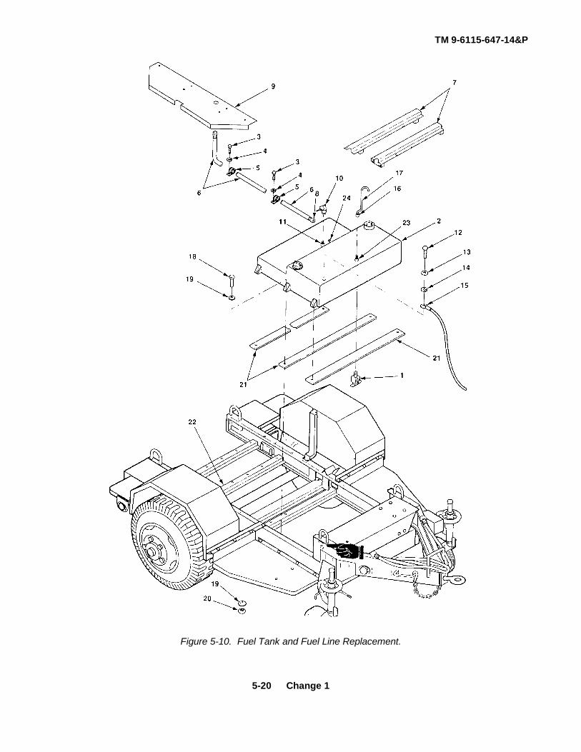
TM 9-6115-647-14&P
Figure 5-10. Fuel Tank and Fuel Line Replacement.
5-20 Change 1

TM 9-6115-647-14&P
5-13. Fuel Tank Repair. (See figure 5-11 ) In addition to component replacement described below, the fueltank may be straightened, welded and repainted. If required, repaint In accordance with MIL-T-704, Type G,Color Green, No. 383 of MIL-C-46168. If power unit Is painted in camouflage, refer to Section VI, Power UnitMarking.
NOTE
Disassemble only to the extent necessary to replace defective components.
a. Disassembly.
(1) Unscrew and remove fuel level gage (1, figure 5-11).
(2) Disconnect P4, P7 fuel cable (2) from fuel level sensor (3) Unscrew and remove fuel level sensor.
(3) Disconnect fuel line (4) from connector (5) Unscrew and remove connector.
(4) Disconnect vent tube (6) from connector (7) Unscrew and remove connector.
NOTE
Chain on cap is attached to filter tube.
(5) Remove non-vented cap (8) and filler neck (9).
(6) Remove six screws (10) and six flat washers (11) and remove filler neck (9) and gasket (12).
(7) Remove drain cock (13).
b. Assembly.
(1) Install drain cock (14).
(2) Position gasket (12) over filler neck hole in fuel tank and aline mounting holes. Insert filler neck (9) in fuel tank (14) and aline mounting holes Install six screws (10) and six flat washers (11).
(3) Install cap (8) on filler neck (9).
(4) Install connector (7) and reattach vent tube (6).
(5) Install connector (5) and reattach fuel line (4).
(6) Install fuel level sensor (3) and reconnect P4, P7 fuel cable (2).
(7) Install fuel level gage (1).
5-21

TM 9-6115-647-14&P
Figure 5-11. Fuel Tank Repair.
Section V. MAINTENANCE OF POWER UNIT TRAILER
5-14. Storage Tray and Cover Repair and Replacement. (See figure 5-12 )
a. Removal.
(1) Remove generator set (paragraph 5-2).
(2) Lower tailgate (1, figure 5-12.
(3) Remove contents of storage tray (2).
(4) Remove 20 screws (3), 20 flat washers (4) and 20 self-locking nuts (5) and removestorage tray cover (6) from generator set supports (7).
NOTE
If storage tray is not being removed, omit step (5).
(5) Remove six screws (8), twelve flat washers (9) and six self-locking nuts (10) andremove storage tray (2) from trailer cross-members (11).
5-22

TM 9-6115-647-14&P
b. Repair Repair of the storage tray and cover is limited to straightening, welding and repainting. Ifrequired, repaint in accordance with MIL-T-704, Type G, Color Green, No 383 of MIL-C-46168. Ifpower unit is painted in camouflage, refer to Section VI, Power Unit Marking.
c. Installation .
NOTE
If storage tray was not being removed, omit step (1).
(1) Position storage tray (2) on trailer cross-members (11) and fasten with six screws (8), twelveflat washers (9) and six self-locking nuts (10). Make sure open end of storage tray is at rear.
(2) Position storage tray cover (6) on underside of rear and rear middle generator supports (7) sothat mounting holes in cover align with mounting holes in generator support ears. Install 20screws (3), 20 flat washers (4) and 20 self-locking nuts (5).
(3) Place accessories in storage tray (6).
(4) Raise and secure tailgate (1), if required.
(5) Install generator set (paragraph 5-2).
5-23

TM 9-6115-647-14&P
Figure 5-12. Storage Tray and Cover Repair and Replacement.
5-15. Repair of Steps, Walkways, Fender Brackets and Tailgate. Repair of the trailer steps, walkways,fender brackets and tailgate is limited to straightening, welding and repainting. If required, repaint inaccordance with MIL-T-704, Type G, Color Green, No 383 of MIL-C-46168. If power unit was painted incamouflage, refer to Section VI, Power Unit Marking.
5-16. Generator Set Support Repair and Replacement. (See figure 5-13.) The power unit has fourgenerator set supports. Replacement procedures are the same for all four, except where noted.
5-24

TM 9-6115-647-14&P
a. Removal.
(1) Remove generator set (paragraph 5-2).
(2) Remove walkways (paragraph 4-31).
(3) Fuel cable is fastened to front support (1, figure 5-13) with one clamp (2) . Fuel line isfastened to front support with one clamp and to middle-front support with two clamps . Whenremoving front or middle-front support, remove screws (4), lockwashers (5) and clamps asnecessary and remove fuel cable and/or fuel line from support.
(4) When removing rear support (6) or middle-rear support (7), remove storage tray cover (8)(paragraph 5-14).
(5) Remove four screws (9), eight flat washers (10) and four self-locking nuts (11) and lift support(1,3,6 or 7) off trailer frame (12).
b Repair. The generator set supports may be repaired by drilling out damaged threaded inserts andreplacing them with new ones, or by welding or repainting. If repaired, repaint in accordance withMIL-T-704, Type G, Color Green, No 383 of MIL-C-46168.
c. Installation.
NOTE
When installing front or middle-front support, position support so that clampmounting holes are center and curbside.
(1) Position support (1,3,6 or 7) on trailer frame (12) and fasten with four screws (9), eight flatwashers (1.0) and four self-locking nuts (11). Torque to 57 to 63 foot-pounds (77.81 to 86.00newton-meters).
(2) When installing rear support (6) or middle-rear support (7), install storage tray cover (8)(paragraph 5-14).
(3) When installing front support (1) or middle-front support (3), reconnect fuel cable and/or fuelline, to supports with screws (4), lockwashers (5) and clamps (2) as necessary.
(4) Install walkways (paragraph 4-31).
(5) Install generator set (paragraph 5-2).
Change 1 5-25

TM 9-6115-647-14&P
Figure 5-13. Generator Set Support Repair and Replacement.
5-26

TM 9-6115-647-14&P
Section VI. POWER UNIT MARKING
5-17. General. Power unit marking is done in accordance with MIL-STD-642 and MIL-STD-130. If required,touch up painting of the base color shall be done in accordance with MIL-T-704, Type F or G, Color Green, No383 of MIL-C-46168. When power unit has been painted in camouflage, replacement parts must be painted tomatch authorized patterns and colors as specified in TB 43-0147. Application of camouflage paint shall bedonein accordance with MIL-C-53072.
5-18. Trailer Marking. (See figure 5-14.) The power unit four-digit registration number, preceded by theprefix "VB", is marked in two places on the power unit trailer. On the fender over each wheel, “TP 50-70 PSI” ismarked in 1 00 ± 12 Inch high characters "TP 65 PSI" is marked over each forward stabilizing wheel on the fueltank curbside, "FUEL FILL" and "FUEL DRAIN" are marked in 50 ± 12 Inch high characters. The work "LIFT" ismarked in 50 ± 12 inch high characters at each of four corner lifting rings. The word "LOCKED" and an arrowpointing to ground is marked in two places on the trailer frame at the handbrakes. Figure 5-14 shows thelocation of trailer markings.
Figure 5-14. Trailer Marking.
5-27

TM 9-6115-647-14&P
5-19. Power Distribution Unit Marking . (See figure 5-15 ) "J1", "J6" and "J10" are marked next to theirrespective connectors on the inside and the outside of the PDU housing. Underneath connector J1, "97403Assy 13227E5855" is marked on the outside of the housing. "E1" is marked next to the ground stud on theinside and outside of the housing. "CR1", "CR2", "CR3", "CR4", "K1", "K2", "K3" and "TB1" are marked next totheir respective components inside the housing. Figure 5-15 shows the location of PDU external markings.
Figure 5-15. Power Distribution Unit Marking.
5-28

TM 9-6115-647-14&P
CHAPTER 6
TEST AND INSPECTION AFTER REPAIR
Section I. GENERAL REQUIREMENTS
6-1. General Requirements. The activity performing the repair is responsible for the performance of allapplicable tests and inspections specified in the technical manuals referenced below. Activities performingmaintenance on any component of the power unit must perform those tests and Inspections required by theapplicable component or system repair instruction.
Section II. INSPECTION
6-2. Generator Set Inspections. Refer to TM 5-6115-465-12 and -34 for inspections required following repairof the generator set.
6-3. Trailer Inspections. Refer to TM 9-2330-247-14&P for inspections required following repair of the trailer.
Section III. OPERATIONAL TESTS
6-4. Generator Set Operational Tests. Refer to TM 5-6115-465-12 and -34 for operational tests required toverify satisfactory performance of the generator set.
6-5. Trailer Operational Tests. Refer to TM 9-2330-247-14&P for operational tests required to verifysatisfactory performance of the trailer.
6-1/(6-2 blank)

TM 9-6115-647-14&P
APPENDIX A
REFERENCES
A-1. Scope. This appendix lists all pamphlets, forms, technical manuals, specifications and miscellaneouspublications referenced in this manual.
A-2. Forms and Records.
Supply Policy Below the Wholesale Level.........................................................................AR-700-2Recommended Changes to Publications and Blank Forms ...............................................DA Form 2028Depreservation Guide for Vehicles and Equipment ...........................................................DA Form 2258Equipment Inspection and Maintenance Worksheet..........................................................DA Form 2404Maintenance Request .......................................................................................................DA Form 2407Consolidated Index of Army Publications..........................................................................DA PAM 25-30The Army Maintenance Management System (TAMMS)...................................................DA PAM 738-750Product Quality Deficiency Report ....................................................................................SF 368
A-3. Military Specifications .
Chemical Agent Resistant Aliphatic Polyurethane Coating................................................MIL-C-46168Chemical Agent Resistant Coating (CARC) System Application Procedure andQ/C Inspection..................................................................................................................MIL-C-53072Identification Marking of U S Military Property ..................................................................MIL-STD-130Identification Marking of Combat and Tactical Transport...................................................MIL-STD-642Treatment and Painting of Materiel ...................................................................................MIL-T-704
A-4. Technical Manuals.
Operator's and Organizational Maintenance Manual for Generator Set,Diesel Engine Driven, Tactical Skid Mtd, 30 KW, 3 Phase, 4 Wire,120/208 and 240/416 V (DOD Model MEP-005A), Utility Class, 50/60 Hz(NSN 6115-00-463-1240), (Model MEP-104A), Precise Class, 50/60 Hz(6115-00-463-1247), (Model MEP-114A), Precise Class, 400 Hz(6115-00-463-1248) Including Auxiliary Equipment (DOD Model MEP-005AWF),Winterization Kit, Fuel Burning (6115-00-463-9083), (Model MEP-005AWE),Winterization Kit, Electric (6115-00-463-9085), (Model MEP-005ALM), LoadBank Kit (6115-00-463-9088) and (MEP-005AWM), Wheel Mounting Kit(6115-00-463-9094) .....................................................................................................TM 5-6115-465-12
A-1

TM 9-6115-647-14&P
Organizational, Direct Support and General Support Maintenance Repair Partsand Special Tools List (including Depot Maintenance Repair Parts and SpecialTools) for Generator Set, Diesel Engine Driven, Tactical Skid Mounted, 30 KW,3 Phase, 4 Wire, 120/208 and 240/416 Volts (DOD Model MEP-005A), UtilityClass, 50/60 Hz (6115-00-118-1240), (Model MEP-104A), Precise Class,50/60 Hz (6115-00-118-1247), (Model MEP-114A), Precise Class, 400 Hz(6115-00-118-1248) including Optional Kits (Model MEP-005AWF), WinterizationKit, Fuel Burning (6115-00-463-9083), (Model MEP-005AWE) Winterization Kit,Electric (6115-00-463-9085), (Model MEP-005ALM) Load Bank Kit(6115-00-463-9088) and (Model MEP-OO5AWM) Wheel Mounting Kit(6115-00-463-9094) . ...................................................................................................TM 5-6115-465-24P
Intermediate (Field) Direct and General Support) and Depot Level MaintenanceManual Generator Set, Diesel Engine Driven, Tactical Skid Mtd, 30 KW, 3 Phase,4 Wire, 120/208 and 240/416 V (DOD Model MEP-005A), Utility, 50/60 Hz(NSN 6115-00-118-1240), (Model MEP-104A), Precise, 50/60 Hz(6115-00-118-1247), (Model MEP-114A), Precise, 400 Hz (6115-00-118-1248)Including Optional Kits (Model MEP-005AWF) Winterization Kit, Fuel Burning(6115-00-463-9083), (Model MEP-005AWE) Winterization Kit, Electric(6115-00-463-9085), (Model MEP-005ALM) Load Bank Kit (6115-00-463-9088)and (Model MEP-005AWM) Wheel Mounting Kit (6115-00-463-9094) ..........................TM 5-6115-465-34Installation Practices for Aircraft and Electric and Electronic Wiring (TO-1-1 A-14) ......TM 55-1500-323-25
Procedures for Destruction of Equipment to Prevent Enemy Use(Mobility Equipment Command)...................................................................................TM 750-244-3Operator's, Organizational, Direct Support and General Support MaintenanceManual Including Repair Parts and Special Tools List for Chassis, Trailer,General Purpose, 3 ½ -Ton, 2-Wheel M353 (NSN 2330-00-542-2831) ..........................TM 9-2330-247-14&P
Organizational, Direct Support, and General Support Care Maintenanceand Repair of Pneumatic Tires and Inner Tubes ...............................................................TM 9-2610-200-24
A-5. Technical Bulletins.
Solder and Soldering (TO 31-3-64) ....................................................................................TB SIG 222Color, Marking and Camouflage Patterns Used on Military Equipment Managed
by USATROSCOM ......................................................................................................TB 43-0147Preservation of USAMECOM Mechanical Equipment forShipment and Storage ......................................................................................................TB 740-97-2
A-2

TM 9-6115-647-14&P
APPENDIX B
COMPONENTS OF END ITEM AND BASIC ISSUE ITEMS LISTS
Section I. INTRODUCTION
B-1. Scope. This appendix lists components of end item and basic issue items for the power unit to help youinventory items required for safe and efficient operation.
B-2. General. The Components of End Item and Basic Issue Items lists are divided Into the following sections.
a. Section II Components of End Item. This listing is for informational purposes only, and is notauthority to requisition replacements. These items are part of the end item, but are removed andseparately packaged for transportation or shipment. As part of the end item, these items must bewith the end item whenever it is issued or transferred between property accounts. Illustrations arefurnished to assist you in identifying the items.
b Section III. Basic Issue Items . These are the minimum essential items required to place thepower unit in operation, to operate it, and to perform emergency repairs . Although shippedseparately packaged, BII must be with the power unit during operation and whenever it is transferredbetween property accounts. The illustrations will assist you with hard-to-identify items. This manualis your authority to request/requisition Bll, based on TOE/MTOE authorization of the end item.
B-3. Explanation of Columns . The following provides an explanation of columns found in the tabular listings.
a. Column (1), Illustration Number (Illus No.) . This column indicates the number assigned to theitem.
b. Column (2). National Stock Number . Indicates the National stock number assigned to the item.
c. Column (3). Description . Indicates the federal item name and, if required, a minimum descriptionto identify and locate the item. The last line for each item indicates the CAGE (in parentheses)followed by the part number. If item needed differed for different models of this equipment, themodel would be shown under the "Usable on Code" heading in this column. The Usable on Code isnot applicable for this equipment.
d. Column (4). Unit of Measure (U/M). Indicates the measure used in performing the actualoperational/ maintenance function. This measure is expressed by a two-character alphabeticalabbreviation (e.g., ea., in, pr).
e Column (5). Quantity Required (Qty Req’d). Indicates the quantity of the item authorized to beused with/on the equipment.
B-1

TM 9-6115-647-14&P
Section II. COMPONENTS OF END ITEM
(1) (2) (3) (4) (5)ILLUS NATIONAL STOCK DESCRIPTION USABLE QTY
NUMBER NUMBER CAGEC and Part Number on Code U/I req’d
1 5975-00-296-5324 Rod, Ground, Driven, Sectional ea 29 ft (2.7 m) (81348) W-R-550 Type III
2 5120-01-013-1676 Hammer, Slide (97403) 13226E7741 ea 1
3 Kit, Intervehicle Power Cable (19207) ea 111682379-1
4 Paralleling Cable, 25 ft (7 6 m) (30554) ea 169-772
5 Power/Control Cable, 75 ft (97403) 13227E5877-1 ea 1
6 Auxiliary Cable, 25 ft (97403) 13227E5877-2 ea 1
7 Control Cable (97403) 13222E1440 ea 1
B-2

TM 9-6115-647-14&P
4880-0090.2
(1) (2) (3) (4) (5)ILLUS NATIONAL STOCK DESCRIPTION USABLE QTY
NUMBER NUMBER CAGEC and Part Number on Code U/I req’d
1 Manual, Technical ea 1TM 9-6115-647-14&P
B-3/(B-4 blank)

TM 9-6115-647-14&P
APPENDIX C
MAINTENANCE ALLOCATION CHART
Section I. INTRODUCTION
C-1. General.
a. This section provides a general explanation of all maintenance and repair functions authorized atvarious maintenance levels.
b. Section II designates overall responsibility for the performance of maintenance functions on theidentified end Item or component. The implementation of the maintenance functions upon the enditem or component will be consistent with the assigned maintenance functions.
c. Section III lists the tools and test equipment required for each maintenance function as referencedfrom Section II.
d. Section IV contains supplemental instructions, explanatory notes and/or illustrations required for aparticular maintenance function.
C-2. Explanation of Columns in Section II.
a. Group Number. Column 1 . The assembly group is a numerical group assigned to each assemblyin a top down breakdown sequence. The applicable assembly groups are listed on the MAC indisassembly sequence beginning with the first assembly removed in a top down disassemblysequence.
b Assembly Group Column 2. This column contains a brief description of the components of eachassembly group.
c. Maintenance Functions. Column 3 . This column lists the various maintenance functions (Athrough K) and indicates the lowest maintenance category authorized to perform these functions.The symbol designations for the various maintenance categories are as follows:
C - Operator or crewO - Unit maintenanceF - Direct support maintenanceH - General support maintenanceD - Depot maintenance
The maintenance functions are defined as follows:
A - Inspect. To determine serviceability of an item by comparing its physical, mechanical, and electricalcharacteristics with established standards.
B - Test. To verify serviceability and to detect electrical or mechanical failure by use of test equipment.
C-1

TM 9-6115-647-14&P
C - Service. To clean, to preserve, to charge, and to add fuel, lubricants, cooling agents, and air. If it isdesired that elements, such as painting and lubricating, be defined separately, they may be so listed.
D - Adjust. To rectify to the extent necessary to bring into proper operating range.
E - Align. To adjust specified variable elements of an item to bring to optimum performance.
F - Calibrate. To determine the corrections to be made in the readings of instruments or test equipment used inprecise measurement. Consists of the comparison of two instruments, one of which is a certified standard ofknown accuracy, to detect and adjust any discrepancy in the accuracy of the instrument being compared withthe certified standard.
G - Install. To set up for use in an operational environment such as emplacement, site, or vehicle.
H - Replace. To replace unserviceable items with serviceable like items.
I - Repair. Those maintenance operations necessary to restore an item to serviceable condition throughcorrection of material damage to a specific failure. Repair may be accomplished at each category ofmaintenance.
J - Overhaul. Normally, the highest degree of maintenance performed by the Army in order to minimize timework in process is consistent with quality and economy of operation. It consists of that maintenance necessaryto restore an item to completely serviceable condition as prescribed by maintenance standard in technicalpublications for each item of equipment. Overhaul normally does not return an item to like new, zero mileage,or zero hour condition.
K - Rebuild. The highest degree of material maintenance. It consists of restoring equipment as nearly aspossible to new conditions in accordance with original manufacturing standards. Rebuild is performed onlywhen required by operational considerations or other paramount factors and then only at the depotmaintenance category. Rebuild reduces to zero the hours or miles the equipment, or component thereof, hasbeen in use.
d. Symbols. The uppercase letter placed in the appropriate column indicates the lowest level at whichthat particular maintenance function is to be performed.
e. Tools and Equipment Column 4 . This column is provided for referencing by code, the specialtools and test equipment, (Section III) required to perform the maintenance functions (Section II).
f. Remarks. Column 5. This column is provided for referencing by code, the remarks (Section IV)pertinent to the maintenance functions.
C-3. Explanation of Columns in Section III . Section III, Tools, Test, and Support Equipment. Requirementsis not applicable.
C-4. Explanation of Columns in Section IV . Section IV, Remarks, is not applicable.
C-2

TM 9-6115-647-14&P
Section II. MAINTENANCE ALLOCATION CHART
C-3

TM 9-6115-647-14&P
Section II. MAINTENANCE ALLOCATION CHART
C-4

TM 9-6115-647-14&P
APPENDIX D
UNIT, DIRECT SUPPORT AND GENERAL SUPPORT ANDDEPOT MAINTENANCE REPAIR PARTS
AND SPECIAL TOOLS LIST
Section I. INTRODUCTION
D-1. Scope. This manual lists repair parts and special tools required for the performance of unit, directsupport, general support and depot maintenance of the power unit.
D-2. General. The Repair Parts and Special Tools List is divided into the following sections:
a. Repair Parts - Section II. A list of repair parts authorized for the performance of maintenance atthe unit, direct support, general support and depot level in figure and item number sequence.
b. Special Tools. Test and Support Equipment - Section III . A list of special tools, test andsupport equipment authorized for the performance of maintenance at the unit, direct support,general support and depot level.
c. National Stock Number and Reference Number Index - Section IV. A list of National stocknumbers in numerical sequence, followed by a list of reference numbers appearing in all the listings, inalphanumeric sequence, cross-referenced to the illustration figure number and item number.
d. Reference Designator Index - Section V. The reference Designator Column includes all assignedreference designators arranged first in alphabetical order, second in numerical order. Opposite eachsymbol is listed the figure and item number of the part in Section II and the reference number.
D-3. Explanation of Columns . The following provides an explanation of columns in the tabular lists inSections II and III.
a. Illustrations. (Column 1) . This column is divided as follows:
(1) Figure number. Indicates the figure number of the illustration on which the item is shown.
(2) Item number. Indicates the number used to identify the item on the illustration.
D-1

TM 9-6115-647-14&P
b. Source, Maintenance, and Recoverability Codes (SMR). (Column 2)
(1) Source codes
GENERAL: Source Codes are assigned to support items to indicate the manner of acquiring support items formaintenance, repair, or overhaul of end items. Source codes are entered in the first and second positions ofthe Uniform SMR Code format as follows:
Code Definition
PA Item procured and stocked for anticipated or known usage.
PB Item procured and stocked for insurance purposes because essentially dictatesthat a minimum quantity be available in the supply systems.
PC Item procured and stocked and which otherwise would be coded PA except that itis deteriorative in nature.
PD Support item, excluding support equipment, procured for initial issue or outfittingand stocked only for subsequent or additional initial issues or outfittings. Notsubject to automatic replenishment.
PE Support equipment procured and stocked for initial issue or outfittings to specifiedmaintenance repair activities.
PF Support equipment which will not be stocked but which will be centrally procuredon demand.
PG Item procured and stocked to provide for sustained support for the life of theequipment. It is applied to an item peculiar to the equipment which because ofprobable discontinuance or shutdown of production facilities would proveuneconomical to reproduce at a later time.
KD An item of depot overhaul/repair kit and not purchased separately. Depot kitdefined as a kit that provides items required at the time of overhaul or repair.
KF An item of maintenance kit and not purchased separately. Maintenance kitdefined as a kit that provides an item that can be replaced at unit or intermediatelevels of maintenance.
KB Item included in both a depot overhaul/repair kit and a maintenance kit.
MO Item to be manufactured or fabricated at unit level.
D-2

TM 9-6115-647-14&P
Code Definition
MF Item to be manufactured or fabricated at general support maintenance levels.
MD Item to be manufactured or fabricated at depot maintenance level.
AO Item to be assembled at unit level.
AF Item to be assembled at direct support maintenance levels.
AH Item to be assembled at general support maintenance levels.
AD Item to be assembled at depot maintenance level.
XA Item is not procured or stocked because the requirements for the item will result inthe replacement of the next higher assembly.
XB Item is not procured or stocked. If not available through salvage, requisition.
XC Installation drawing, diagram, instruction sheet, field service drawing, that isidentified by manufacturer's part number.
XD A support item that is not stocked. When required, item will be procured throughnormal supply channels.
(2) Maintenance codes GENERAL: Maintenance Codes are assigned to indicate the levels ofmaintenance authorized to USE and REPAIR support items. The Maintenance Codes are inthe third and fourth position of the Uniform SMR Code Format.
(a) Use (third position ): The Maintenance Code entered in the third position indicates thelowest level maintenance level authorized to remove, replace, and use the support item.The Maintenance Code entered in the third position indicates one of the following levelsof maintenance.
Code Application/Definition
O Support item is removed, replaced, used at the unit level of maintenance.
F Support item is removed, replaced, used at direct support levels.
H Support Item is removed, replaced, used general support levels.
Code Definition
D Support items that are removed, replaced, used at depot only. Depot, MobileDepot and Specialized Repair Activity.
D-3

TM 9-6115-647-14&P
(b) Repair (fourth position): The maintenance code entered in the fourth position indicateswhether the item is to be repaired and identifies the lowest maintenance level with thecapability to perform complete repair (i.e., all authorized maintenance functions).
Code Application/Definition
O The lowest maintenance level capable of complete repair of the support item isthe unit level.
F The lowest maintenance level capable of complete repair of the support item isdirect support level.
H The lowest maintenance level capable of complete repair of the support item isgeneral support level.
Code Definition
D The lowest maintenance level capable of complete repair of the support item isthe depot level Depot, Mobile Depot, and Specialized Repair Activity.
Code Definition
L Repair restricted to designated. Specialized Repair Activity.
Z Nonreparable. No repair is authorized.
B No repair is authorized. The item may be reconditioned by adjusting, lubricating,etc., at the user level. No parts or special tools are procured for the maintenanceof this item.
(3) Recoverability codes. GENERAL: Recoverability Codes are assigned to support items toindicate the disposition action on unserviceable items. The recoverability code is entered inthe fifth position of the uniform SMR Code Format as follows:
RecoverabilityCode Definition
Z Nonreparable item. When unserviceable, condemn and dispose at the levelindicated in column 3.
O Reparable Item. When uneconomically reparable, condemn and dispose at unitlevel.
F Reparable item. When uneconomically reparable, condemn and dispose at directsupport level.
H Reparable Item. When uneconomically reparable, condemn and dispose atgeneral support level.
D-4

TM 9-6115-647-14&P
RecoverabilityCodes Definition
D Reparable item. When beyond lower level repair capability, return to depot. Condemnation and disposal not authorized below depot level.
L Reparable item. Repair, condemnation and disposal not authorized below depot/Specialized Repair Activity level.
A Item requires special handling or condemnation procedure because of specific reasons (i e , precious metal content, high-dollar value, critical materiel or hazardous material). Refer to appropriate manuals/directives for specific instructions.
c. National Stock Number (Column 4) . Indicates the National Stock Number assigned to the itemand will be used for requisitioning purposes.
d. Description (Column 5) . Indicates the Federal item name and any additional descriptions of theitem required. The abbreviation "w/e" when used as a part of the nomenclature, indicates that the NationalStock Number includes all armament, equipment, accessories and repair parts issued with the item. A partnumber or other reference number is followed by the applicable five digit Federal Supply Code forManufacturer in parentheses. If two reference numbers and Federal Supply Codes for Manufacturer are listed,the first listing refers to the Department of Defense Drawing Number, the second listing refers to the actual partmanufacturer items that are included in kits and sets are listed below the name of the kit or set with the quantityof each item in the kit or set indicated in the quantity incorporated in unit column.
e. Unit of Measure (U/M) (Column 6) . Indicates the standard of the basic quantity of the listed itemas used in performing the actual maintenance function. This measure is expressed by a two-characteralphabetical abbreviation (e g, ea, in, pr etc ) . When the unit of measure differs from the unit of issue, thelowest unit of issue that will satisfy the required units of measure will be requisitioned.
f. Quantity Incorporated in Unit (Column 7) . Indicates the quantity of the item used in the assemblygroup. A "V" appearing in this column in lieu of a quantity indicates that a definite quantity cannot be indicated(e g , shims, spacers, etc.).
D-4 Special Information .
a. Identification of Usable On Codes for this manual is not applicable.
b. Army unit maintenance personnel will extract the items which they require from Section II, 3rd or 4thposition of column 2 of the direct and general support RPSTL. Parts which are manufactured or assembled ata higher level than that authorized to install the part are indicated by the use of higher level code in the sourcecolumn.
c. Stockage Information. Army stockage is demand based in accordance with AR 710-2. Repair partslisted in this publication represent those authorized for use at indicated maintenance levels and will berequisitioned on an as-required basis until stockage is justified in accordance with AR 710-2.
D-5

TM 9-6115-647-14&P
d. In the parts list, some items are indented to show that they are a component of the item under whichthey are indented.
D-5 How to Locate Repair Parts.
a. When National Stock Number or Reference Number is Unknown:
(1) Using the table of contents, determine the functional group, i.e., batteries and related parts,exhaust and breather pipes, within which the repair part belongs. This is necessary since illustrations areprepared for functional groups.
(2) Find the illustration covering the functional group to which the repair part belongs.
(3) Identify the repair part on the illustration and note the illustration figure and item number of therepair part.
(4) Using the Repair Parts Listing, find the figure and item number noted on the illustration.
b. When National Stock Number or Reference Number is Known:
(1) Using the index of National Stock Numbers and Reference Numbers, find the pertinentnational stock number or reference number. This index is in ascending NSN sequence followed by a list ofreference numbers in alphanumeric sequence, cross-referenced to the illustration figure number and itemnumber.
(2) After finding the figure and item number, locate the figure and item number in the repair partslist.
D-6. Use of the Reference Designator Index Section. This Section (Section V) is used when the referencedesignator is known or identified by other technical manuals supporting this equipment. The reference numberis given in this section if description or location is desired, note the figure and item number. Turn to Section IIto the noted figure and item number. The location of the part and description is given in this listing.
D-7 Abbreviations.
Abbreviations Explanation
Not Applicable
D-8 Commercial and Government Entity Code .
Code Manufacturer
Not Applicable
D-9. Recommendation for Maintenance Publication Improvements . Report of errors, omissions, andrecommendations for improving this publication by the individual user is encouraged. Reports should besubmitted directly to Commander, US Army Troop Support Command, ATTN: AMSTR-MCTS, 4300Goodfellow Boulevard, St. Louis, MO 63120-1798.
D-6

TM 9-6115-647-14&P
Figure D-1. Generator Set (Sheet 1 of 2).
Change 1 D-7

TM 9-6115-647-14&P
Figure D-1. Generator Set (Sheet 2 of 2).
D-8

TM 9-6115-647-14&P
(1) (2) (3) (4) (5) (6) (7) (8)ILLUS SMR CODE USMC DESCRIPTION
TRATION QTY USMCUSABLE INC QTY
a b a b c d a b NATIONAL REF NUMBER ON U/M IN PERFIG ITEM AIR REPL STOCK & MFR CODE CODE UNITEQUIPNO NO ARMY FORCE NAVY USMC SSI FACTOR NUMBER
Group 01 - GENERATOR SET
D-1 1 PAOZZ 5306 00 225 9498 SCREW,CAP EA 4MS90725 33 96906
D-1 2 PAOZZ 5310 00 081 4219 WASHER, FLAT EA 4MS27183-12 96906
D-1 3 PAOZZ 5310 00 984 3806 NUT, SELF-LOCKING EA 4MS51922 9 96906
D-1 4 PAOZZ 4730 00 908 3195 CLAMP, HOSE EA 8MS35842 10 96906
D-1 5 PAOZZ ELBOW, 90° EA 213227E5848 1 9740339T3 8-8 88303
D 1 6 PAOZZ 4730 01 231-1740 ADAPTER EA 213227E5879 97403
0-1 7 PAOZZ 5305 00 071-2511 SCREW, CAP EA 4MS90725 15 96906
D-1 8 PAOZZ 5310-00 582-5965 LOCKWASHER, SPRING EA 4MS35338 44 96906
D-1 9 PAOZZ 5365 01 031-1798 SPACER EA 413220E8192 97403
D-1 10 PDFFD 6115-00 118-1248 GENERATOR SET EA 4MEP-114A 30554
D 1 11 PAOZZ 5305 00 724 5914 SCREW,CAP EA 8MS90725-167 96906
D 1 12 PAOZZ 5310-00 8206653 LOCKWASHER, SPRING EA 8MS35338 50 96906
D-9

TM 9-6115-647-14&P
Figure D-2. Adapter Plate Assembly (Sheet 1 of 3).
D-10Change 1

TM 9-6115-647-14&P
Figure D-2. Adapter Plate Assembly (Sheet 2 of 3).
Change 1 D-11

TM 9-6115-647-14&P
Figure D-2. Adapter Plate Assembly (Sheet 3 of 3).
D-12Change 1

TM 9-6115-647-14&P
(1) (2) (3) (4) (5) (6) (7) (8)ILLUS SMR CODE USMC DESCRIPTION
TRATION QTY USMCUSABLE INC QTY
a b a b c d a b NATIONAL REF NUMBER ON U/M IN PERFIG ITEM AIR REPL STOCK & MFR CODE CODE UNITEQUIPNO NO ARMY FORCE NAVY USMC SSI FACTOR NUMBER
Group 02 - ELECTRICAL SYSTEM0201 - Adapter Plate Assy
D-2 1 MDOFF PLATE ASSY, ADAPTER EA 113227E5859 97403
D-2 2 PAFZZ 5305-00-059-3661 SCREW, CROSS-RECESSED EA 4MS51958-65 96906
D-2 3 PAFZZ 5310-00-014-5850 WASHER, FLAT EA 4MS27183-42 96906
D-2 4 PAFZZ 5310-00-877-5797 NUT, SELF-LOCKING EA 4MS21044N3 96906
D-2 5 PAFZZ 5935-00-060-2294 COVER, PROTECTIVE EA 1MS17349C40B 96906
D-2 6 PAFZZ 5999-01-181-8436 GASKET, RECEPTACLE, EMI EA 113226E7052-4 97403
D-2 7 PBFFF WIRING HARNESS, J3 EA 113227E5870 97403MANUFACTURE FROM
D-2 8 PAFZZ 597500-727-5153 STRAP, TIEDOWN 96906 EA VMS3367-4-9
D-2 9 PAFZZ 5940-00-283-5280 TERMINAL, LUG EA 4MS25036-106 96906
D-2 10 PAFZZ 5970-00-914-3118 SLEEVING, INSULATION FT VMS23053/5-109-0 81349
D-2 11 PAFZZ 5970-00-954-1622 SLEEVING INSULATION FT VMS23053/5-105-0 81349
D-2 12 PAFZZ 6145-01-1959844 WIRE, ELECTRICAL, 16 AWG FT V(J3 TO TB2-1, TB2-3,TB2-4 AND TB2-5)M16878/8BJE9 81349
D-2 13 PAFZZ 6145-01-197-2687 WIRE, ELECTRICAL, 1 AWG FT V(J3 TO L1 THRU L3 AND GROUND)M1687818BTM9 81349
D-2 14 PAFZZ 5935-01-181-8405 CONNECTOR, RECEPTACLE EA 1MIS20045/2-019 18876
0-2 15 PAFZZ PROTECTOR, SURGE EA 313228E1908 97403
D-2 16 PAFZZ 5940-00-115-4999 TERMINAL, LUG EA 1MS20659-134 96906
D-2 17 PAFZZ 5305-00-054-5650 SCREW, CROSS-RECESSED EA 4MS51957-16 96906
Change 1 D-13

TM 9-6115-647-14&P
(1) (2) (3) (4) (5) (6) (7) (8)ILLUS SMR CODE USMC DESCRIPTION
TRATION QTY USMCUSABLE INC QTY
a b a b c d a b NATIONAL REF NUMBER ON U/M IN PERFIG ITEM AIR REPL STOCK & MFR CODE CODE UNITEQUIPNO NO ARMY FORCE NAVY USMC SSI FACTOR NUMBER
Group 02 - ELECTRICAL SYSTEM0201 - Adapter Plate Assy (Cont)
D-2 18 PAFZZ 5310-00-950-1310 WASHER, FLAT EA 4MS27183-4 96906
D-2 19 PAFZZ 5310-00-088-0551 NUT SELF-LOCKING EA 4MS21044N04 96906
D-2 20 PAFZZ 5999-01-198-6172 GASKET, RECEPTACLE, EMI EA 113226E7052-1 97403
D-2 21 MDFFF WIRING HARNESS, J4 EA 113227E5842 97403MANUFACTURE FROM
D-2 22 PADZZ 5975-00-727-5153 STRAP, TIEDOWN EA VMS3367-4-9 96906
D-2 23 PAFZZ 5940-00-283-5280 TERMINAL, LUG EA 2MS25036-106 96906
D-2 24 PAFZZ 5970-00-815-1295 SLEEVING, INSULATION FT VM23053/5-106-0 81349
D-2 25 PAFZZ 6145-00-2952812 WIRE, ELECTRICAL, 16 AWG FT V(J4 TO TB2-2 AND TB2-5)M16878/4BJE9 81349
D-2 26 PAFZZ 5935-01-190-6729 CONNECTOR, RECEPTACLE EA 1D38999/20FD5SN 81349
D-2 27 PAFZZ 6150-00-838-4952 JUMPER, TERMINAL BOARD EA 1TBJA 81349
D-2 28 MDOFF STRIP, MARKER EA 113222E9687-6 97403MS37TB-5 6ME-7E 75382
D-2 29 PAFZZ 5305-00-054-6655 SCREW, CROSS-RECESSED EA 2MS51957-31 96906
D-2 30 PAFZZ 5940-00-983-6046 BOARD, TERMINAL, TYPE 37TB5 EA 1MIL-T-5516411 81349
D-2 31 MDOFF PLATE, ADAPTER EA 113227E5860 97403
D-2 32 PAOZZ 5305-00-068-0502 SCREW, CAP EA 6MS90725-6 96906
D-2 33 PAOZZ 5310-00-582-5965 WASHER, LOCK-SPRING EA 9MS35338-44 96906
D-2 34 PAFZZ 5305-00-068-0501 SCREW, CAP EA 3MS90725-5 96906
D-14Change 1

TM 9-6115-647-14&P
(1) (2) (3) (4) (5) (6) (7) (8)ILLUS SMR CODE USMC DESCRIPTION
TRATION QTY USMCUSABLE INC QTY
a b a b c d a b NATIONAL REF NUMBER ON U/M IN PERFIG ITEM AIR REPL STOCK & MFR CODE CODE UNITEQUIPNO NO ARMY FORCE NAVY USMC SSI FACTOR NUMBER
Group 02 - ELECTRICAL SYSTEM0201 - Adapter Plate Assy (Cont)
D-2 35 PAFZZ 5310-00-809-4058 WASHER, FLAT EA 3MS27183-10 96906
D-2 36 PAFZZ 5310-00-761-6882 NUT, HEX EA 3MS51967-2 96906
D-2 37 PAFZZ TERMINAL, LOAD EA 113228E1924 97403
D-2 38 PAFZZ 5310-00-045-5218 WASHER, FLAT EA 3MS15795-918 96906
D-2 39 PAFZZ 5310-00-897-6082 NUT, PLAIN, HEX EA 2MS35691-36 96906
D-2 40 PAFZZ 5310-00-577-5354 WASHER, LOCK-SPRING EA 2MS35338-105 96906
D-2 41 MFFFF WIRE ASSEMBLY, GROUND EA 113220E0697-6 97403MANUFACTURE FROM
D-2 42 PAFZZ WIRE, 6 AWG FT VHW-C6(127)JO 81349
D-2 43 MFOFF WIRE ASSEMBLY,GROUND EA 113220E0697-5 97403MANUFACTURE FROM
D-2 44 PAFZZ 6145-01-197-2687 WIRE, 1 AWG EA 1M16878/8BTM9 81349
D-2 45 PAFZZ 5940-00-115-4999 TERMINAL, LUG FT VMS20659-134 96906
D-2 46 PAFZZ 9905-00-477-4137 NAMEPLATE, GROUND EA 113211E6730 97403
D-2 47 PAFZZ 5303-00-253-5615 SCREW, DRIVE EA 2MS21318-21 96906
Change 1 D-15

TM 9-6115-647-14&P
Figure D-3. Power/Control and Auxiliary Cables.
D-16Change 1

TM 9-6115-647-14&P
(1) (2) (3) (4) (5) (6) (7) (8)ILLUS SMR CODE USMC DESCRIPTION
TRATION QTY USMCUSABLE INC QTY
a b a b c d a b NATIONAL REF NUMBER ON U/M IN PERFIG ITEM AIR REPL STOCK & MFR CODE CODE UNITEQUIPNO NO ARMY FORCE NAVY USMC SSI FACTOR NUMBER
0202 - Power/Control Cables
D-3 1 CABLE, POWER/CONTROL, 75 FT (PRIMARY EA 1POWER DISTRIBUTION UNIT TO iCC/CRG)13227E5877-1 97403
D 3 2 MOOZZ CABLE, POWER/CONTROL, 25 FT, AUXILIARY, EA 1P10, P11 (AUXILIARY ADAPTER PLATE ASSYTO PRIMARY POWER DISTRIBUTION UNIT)13227E5877 2 97403
MANUFACTURE FROMD 3 3 PADZZ 5970 00-834 9119 SLEEVING, INSULATION FT V
M23053/5-112 0 81349
D 3 4 PADZZ 6145-01 143 0040 SLEEVE, CABLE EA 213226E1336-1 97403
D 3 5 PAOZZ 6145 01-135-5951 CABLE, POWER FT V13222E8995 97403
D 3 6 PADZZ 5970 00 789 6832 SLEEVING, INSULATION FT VM23053/5 114-0 81349
D-3 7 PADOZZ 5935 01-136-9896 CONNECTOR, PLUG (MIS20045/I1-029) EA 113226E1440 97403
0 3 8 PADZZ 5934 01-137 3101 CONNECTOR, PLUG (MIS20045/1 028) EA 113226E1410 97403
D-17

TM 9-6115-647-14&P
Figure D-4. Control Cable.
D-18

TM 9-6115-647-14&P
(1) (2) (3) (4) (5) (6) (7) (8)ILLUS SMR CODE USMC DESCRIPTION
TRATION QTY USMCUSABLE INC QTY
a b a b c d a b NATIONAL REF NUMBER ON U/M IN PERFIG ITEM AIR REPL STOCK & MFR CODE CODE UNITEQUIPNO NO ARMY FORCE NAVY USMC SSI FACTOR NUMBER
0203- Control Cable
0 4 1 CABLE, POWER DISTRIBUTION UNIT TO ELECTRIC EA 1CONTROL SYSTEM13222E1440 97403
MANUFACTURE FROM2 PADOZZ SLEEVE, CABLE EA 2
13226E 1336-3 97403
3 PADZZ 5970 00-812 1356 SLEEVING, INSULATION EA 2M23053/5-111-0 81349
4 PADZZ 6145-01 182-8781 CABLE FT VMIS20076/11 005 18876
5 PADZZ SLEEVING, INSULATION FT VM2305315-113-0 81349
6 PADZZ 5935 01 182 8884 CONNECTOR, PLUG EA 2MIS20045/1 015 18876
D-19

TM 9-6115-647-14&P
Figure D-5. P3 Power/Control Cable.
D-20

TM 9-6115-647-14&P
(1) (2) (3) (4) (5) (6) (7) (8)ILLUS SMR CODE USMC DESCRIPTION
TRATION QTY USMCUSABLE INC QTY
a b a b c d a b NATIONAL REF NUMBER ON U/M IN PERFIG ITEM AIR REPL STOCK & MFR CODE CODE UNITEQUIPNO NO ARMY FORCE NAVY USMC SSI FACTOR NUMBER
0204 - Power/Control Cable
D-5 1 CABLE, POWER/CONTROL, P3 (POWER EA 1DISTRIBUTION UNIT TO ADAPTER PLATE ASSY)13227E5868 97403MANUFACTURE FROM
D 5 2 PADZZ 5970 00 954 1622 SLEEVING, INSULATION FT VM23053/5 105-0 81349
D 5 3 PADZZ 5979 00 914 3118 SLEEVING, INSULATION FT VM23053/5-109 0 81349
D-S 4 PADZZ 5950 00 812 2967 SLEEVING, INSULATION FT VM23053/5-108 0 81349
D 5 5 PADZZ 5970-00 834-9119 SLEEVING, INSULATION FT VM23053/5 112-0 81349
D-5 6 PAOZZ 6145 01-143 0040 SLEEVE, CABLE EA 113226E1336-1 97403
D 5 7 PADZZ 5940 00 113 -8190 TERMINAL, LUG EA 1MS25036-122 96906
D-5 8 PADZZ 5940 00 283 5280 TERMINAL, LUG EA 4MS25036 106 96906
D 5 9 PADZZ 5940 00 115 5007 TERMINAL, LUG EA 3MS25036 130 96906
D-5 10 PADZZ 6145 01-135 5951 CABLE, POWER FT V13222E8995 97403
D-5 11 PADZZ 5970 00 789 6832 SLEEVING, INSULATION FT VM23053/5 114 0 81349
D 5 12 PADZZ 5935-01-136-9896 CONNECTOR, PLUG EA 113226E1440 97403
D-5 13 PAOZZ 5305 00 993 1848 SCREW, MACHINE EA 2MS35207-265 96906
D 5 14 PAOZZ 5310 00 014 5850 WASHER, FLAT EA 3MS27183 42 96906
D-5 15 PAOZZ 5310 00-877-5797 NUT, SELF LOCKING EA 3MS21044N3 96906
D 5 16 PAOZZ 5340 01-196 0276 CLAMP, LOOP EA 3MS21919WCG27 96906
D-5 11 PAOZZ 5305-00 995-3441 SCREW, MACHINE EA 1MS35207-269 96906
D 5 18 PAOZZ 5365 00-294 0580 SPACER EA 1NAS43DD3-48 80205
D-5 19 PAOZZ 5975 00 100 8776 LOCKNUT, CONDUIT EA 113215E7892 6 97403
D-5 20 PAOZZ 5330 01-181 8380 GASKET, EMI EA 113226E7768-2 9740382-11561 07700
D 5 21 PAOZZ 3120 01 181 9363 BUSHING EA 113226E6162 2 97403
D-21

TM 9-6115-647-14&P
(1) (2) (3) (4) (5) (6) (7) (8)ILLUS SMR CODE USMC DESCRIPTION
TRATION QTY USMCUSABLE INC QTY
a b a b c d a b NATIONAL REF NUMBER ON U/M IN PERFIG ITEM AIR REPL STOCK & MFR CODE CODE UNITEQUIPNO NO ARMY FORCE NAVY USMC SSI FACTOR NUMBER
0204 - Power/Control Cable (Cont)D 5 22 XDDZZ SEALING GRIP, CABLE, EMI EA 1
13226E9502-1 97403D 5 23 PAOZZ GRIP, CABLE EA 1
13226E9503-2 97403004-04-010 81992
D-22

TM 9-6115-647-14&P
Figure D-6. P4, P7 Fuel Cable.
(D-23 blank)/D-24

TM 9-6115-647-14&P
(1) (2) (3) (4) (5) (6) (7) (8)ILLUS SMR CODE USMC DESCRIPTION
TRATION QTY USMCUSABLE INC QTY
a b a b c d a b NATIONAL REF NUMBER ON U/M IN PERFIG ITEM AIR REPL STOCK & MFR CODE CODE UNITEQUIPNO NO ARMY FORCE NAVY USMC SSI FACTOR NUMBER
0205- Fuel Cable
D 6 1 MOOFF CABLE ASSEMBLY P4, P7 (ADAPTER PLATE EA 1ASSY TO FUEL TANK)13227E5869 97403
MANUFACTURE FROMD-6 2 PAFZZ 5970 00-954-1624 SLEEVING. INSULATION FT V
M23053/5-107-0 81349
D 6 3 PAFZZ 6145-01 129 6897 CABLE FT V13222E1427 97403OOC-04A-ABK 90484
D-6 4 PAFZZ CONNECTOR, ELECTRICAL, P4 EA 1D38999/26FD5PN 81349
D-6 5 PAFZZ 5935-00-813-4717 CONNECTOR, ELECTRICAL P7 EA 1MS3106R14S-2S 96906
D 6 6 PAFZZ BACKSHELL, 90 ° EA 113226E6147 12 97403390HA002M15D4HA 06324
D-6 7 PAFZZ BACKSHELL,90° EA 113226E6147-15 97403390BA002N1404HA 06324
D-6 8 PAOZZ 5305 00-993 1848 SCREW, MACHINE EA 1MS35207-265 96906
D-6 9 PAOZZ 5310-00-045-3296 LOCKWASHER, SPRING EA 1MS35338-43 96906
D-6 10 PAOZZ 5340 01-148 3722 CLAMP, LOOP EA 1MS21919WCG6 96906
D-25

TM 9-6115-647-14&P
Figure D-7. P12, J11 Wiring Harness.
D-26

TM 9-6115-647-14&P
(1) (2) (3) (4) (5) (6) (7) (8)ILLUS SMR CODE USMC DESCRIPTION
TRATION QTY USMCUSABLE INC QTY
a b a b c d a b NATIONAL REF NUMBER ON U/M IN PERFIG ITEM AIR REPL STOCK & MFR CODE CODE UNITEQUIPNO NO ARMY FORCE NAVY USMC SSI FACTOR NUMBER
0206 - Wiring Harness
D-7 1 MFOFF WIRING HARNESS, P12, J11 (ADAPTER PLATE ASSY TO EA 1GENERATOR SET)13227E5843 97403MANUFACTURE FROM
D-7 2 PAFZZ 5975-00-727-5153 STRAP, TIEDOWN EA VMS3367-4-9 96906
D-7 3 PAFZZ 5940-00-283-5280 TERMINAL, LUG EA 5MS25036-106 96906
D-7 4 PAFZZ 5970-00-812-2967 SLEEVING, INSULATION FT VM23053/5-108-0 81349
D-7 5 PAFZZ 5970-00-954-1622 SLEEVING, INSULATION FT VM23053/5-105-0 81349
D-7 6 PAFZZ 6145-00-295-2812 WIRE, ELECTRICAL, 16 AWG FT VM16878/4BJE9 81349
D-7 7 PAFZZ 5935-00-823-5322 PLUG, END, SEAL, CONNECTOR EA 15MS25251-16 96906
D-7 8 PAFZZ 5935-00-725-8233 CONNECTOR P12 EA 1MS3106R20-29S 96906
D-7 9 PAFZZ 5935-00-819-5865 CONNECTORJ11 EA 1MS3101R20-29P 96906
Change 1 D-27

TM 9-6115-647-14&P
Figure D-8. Ground Wire Assemblies.
D-28 Change 1

TM 9-6115-647-14&P
(1) (2) (3) (4) (5) (6) (7) (8)ILLUS SMR CODE USMC DESCRIPTION
TRATION QTY USMCUSABLE INC QTY
a b a b c d a b NATIONAL REF NUMBER ON U/M IN PERFIG ITEM AIR REPL STOCK & MFR CODE CODE UNIT EQUIPNO NO ARMY FORCE NAVY USMC SSI FACTOR NUMBER
0207 - Ground Wire AssyD-8 1 MFOFF WIRE ASSEMBLY, GROUND (POWER DISTRIBUTION EA 1
UNIT GROUND TO TRAILER GROUND)13220E0669-7 97403
D-8 2 MFOFF WIRE ASSEMBLY, GROUND (FUEL TANK GROUND EA 1TO TRAILER GROUND)13220E0669-8 97403
D-8 3 MFOFF WIRE ASSEMBLY, GROUND (GENERATOR GROUND EA 1TO TRAILER GROUND)13220E0697-4 97403MANUFACTURE FROM
D-8 4 PAFZZ 5940-00-113-8190 TERMINAL, LUG (USED ON 13220E0669-7 AND -8) EA 2MS25036-122 96906
PAFZZ 5940-00-113-8190 TERMINAL, LUG (USED ON 13220E0697-4) EA 1MS25036-122 96906
D-8 5 PAFZZ 6145-01-196-0273 WIRE,SIZE6 FT VHW-C6(127)JO 81349
D-8 6 PAOZZ 5305-00-269-3206 SCREW, CAP EA 1MS90725-55 96906
D-8 7 PAOZZ 5310-00-187-2413 WASHER, FLAT EA 1AN961-616T 81352
D-8 8 PAOZZ 5310-00-0228847 LOCKWASHER, INTERNAL TOOTH EA 1MS35333-110 96906
D-8 9 PAOZZ 5305-00-984-7342 SCREW, MACHINE EA 4MS35191-274 96906
D-8 10 PAOZZ 5310-00-014-5850 WASHER, FLAT EA 4MS27183-42 96906
D-8 11 PAOZZ 5310-00-877-5797 NUT, SELF-LOCKING EA 4MS21044N3 96906
D-8 12 PAOZZ 5340-01-228-5831 STRAP ASSY EA 213220E0670-10 97403
Change 1 D-29/(D-30 blank)

TM 9-6115-647-14&P
4880-009.1
Figure D-9. Power Distribution Unit (Sheet 1 of 4).
D-31

TM 9-6115-647-14&P
4880-009.2
Figure D-9. Power Distribution Unit (Sheet 2 of 4).
D-32

TM 9-6115-647-14&P
4880-009.3
Figure D-9. Power Distribution Unit (Sheet 3 of 4).
D-33

TM 9-6115-647-14&P
4880-009.4
Figure D-9. Power Distribution Unit (Sheet 4 of 4).
D-34

TM 9-6115-647-14&P
(1) (2) (3) (4) (5) (6) (7) (8)ILLUS SMR CODE USMC DESCRIPTION
TRATION QTY USMCUSABLE INC QTY
a b a b c d a b NATIONAL REF NUMBER ON U/M IN PERFIG ITEM AIR REPL STOCK & MFR CODE CODE UNITEQUIPNO NO ARMY FORCE NAVY USMC SSI FACTOR NUMBER
0208 - Power Distribution Unit
D-9 1 MDOOF POWER DISTRIBUTION UNIT EA 113227E5855 97403MANUFACTURED FROM
D-9 2 PAFZZ 5305-00-059-3661 SCREW,CROSS-RECESSED EA 21MS51958-65 96906
D-9 3 PAOZZ 5310-00-014-5850 WASHER,FLAT EA 17MS2718342 96906
D-9 4 PAOZZ 5310-00-877-5797 NUT,SELF-LOCKING EA 29MS21044N3 96906
D-9 5 PAFFZ COVER,ENCLOSURE EA 113227E5857 97403
D-9 6 PAFZZ 5320-00-616-5549 RIVET,BLIND EA 6MS20600-MP4W3 96906
D-9 7 MDFZZ SCHEMATIC DIAGRAM EA 113227E5888 97403
D-9 8 PAFZZ 5320-00-208-9632 RIVET EA 2MS20427-4C7 96906
D-9 9 PBFZZ STRIKE,HOOK EA 113227E5844-1 97403
D-9 10 PAFZZ RIVET EA 8MS20427-4C6 96906
D-9 11 PAFZZ 5340-01-054-6092 HINGE,BUTT EA 1MS35826-10C 96906
D-9 12 PAFZZ 599901-181-8435 STRIP,SEALING EA V13227E9695-3 97403
D-9 13 PAFZZ 5340-01-148-3722 CLAMP,LOOP EA 5MS21919WCG6 96906
D-9 14 PAOZZ 593504-060-2294 COVER,PROTECTIVE EA 2MS17349C40B 96906
D-9 15 PAOZZ 593040060-2286 COVER,PROTECTIVE EA 1MS17349C24B 96906
D-9 16 PAOZZ 530500-054-6656 SCREW,CROSS-RECESSED EA 8MS51957-32 96906
D-9 17 PAOZZ 5310-00-182-1404 WASHER,FLAT EA 4MS271836 96906
D-9 18 PAOZZ 5310-000818087 NUT,SELF-LOCKING EA 8MS21044N06 96906
Change 1 D-35

TM 9-6115-647-14&P
(1) (2) (3) (4) (5) (6) (7) (8)ILLUS SMR CODE USMC DESCRIPTION
TRATION QTY USMCUSABLE INC QTY
a b a b c d a b NATIONAL REF NUMBER ON U/M IN PERFIG ITEM AIR REPL STOCK & MFR CODE CODE UNITEQUIPNO NO ARMY FORCE NAVY USMC SSI FACTOR NUMBER
0208 Power Distribution Unit (Cont)
D-9 19 PAFZZ 5999-01-181-8436 GASKET,EMI EA 213226E7052-4 97403
D-9 20 PAFZZ 5999-01-181-8436 GASKET,EMI EA 113226E7052-2 97403
D-9 21 PAFZZ 615000-838-4952 JUMPER,TERMINAL BOARD EA 2TBJA 81349
D-9 22 PAFZZ MARKER STRIP EA 113222E9687-2 97403MS37TB-18-GME-7E 75382
D-9 23 PAFZZ 5940-00-983-6059 BOARD,TERMINAL EA 137TB18 81349
D-9 24 PAOZZ 5943-00-435-1833 RELAY K3 EA 1M575723-003 81349
D-9 25 PAFZZ 5310-00-934-9765 NUT,PLAIN EA 4MS35650-304 96906
D-9 26 PAFZZ 5310-00019-0627 LOCKWASHER,INTERNAL TOOTH EA 4MS35333-107 96906
D-9 27 PAFZZ 531000-138-4315 WASHER,FLAT EA 8MS51859-5 96906
D-9 28 PAFZZ SLEEVE,SPACER EA 4NAS47N3A006 80205
D-9 29 PAFZZ DIODE,(1N1202A) EA 4MIL-S-19500/260 80131
D-9 30 BRACKET,RELAY/DIODE EA 113227E5858 97403
D-9 31 MFFZZ LEAD,ELECTRICAL EA 113227E5878-1 97403
D-9 32 MFFZZ LEAD,ELECTRICAL EA 113227E5878-2 97403
D-9 33 MFFZZ LEAD,ELECTRICAL EA 113227E5878-3 97403MANUFACTURE FROM
D-9 34 PADZZ 5940-00-1155007 TERMINAL,LUG EA 6MS25036-130 96906
D-9 35 PADZZ 5970-00-914-3118 SLEEVING,INSULATION EA 9M23053/5-109-0 81349
D-9 36 PADZZ 6145-01-197-2687 WIRE,1 AWG FT VM16878/8BTM9 81349
D-36 Change 1

TM 9-6115-647-14&P
(1) (2) (3) (4) (5) (6) (7) (8)ILLUS SMR CODE USMC DESCRIPTION
TRATION QTY USMCUSABLE INC QTY
a b a b c d a b NATIONAL REF NUMBER ON U/M IN PERFIG ITEM AIR REPL STOCK & MFR CODE CODE UNITEQUIPNO NO ARMY FORCE NAVY USMC SSI FACTOR NUMBER
0208 - Power Distribution Unit
D-9 37 PAFZZ 5945-01-165-1065 CONTACTOR EA 2D70-501 30554
D-9 38 PAOZZ 5310-01-78-5996 NUT,WING EA 1MS35425-75 96906
D-9 39 PAOZZ 531000-187-2413 WASHER,FLAT EA 5AN961-616T 81352
D-9 40 PAOZZ 5310-00-410-3023 NUT,PLAIN EA 3MS35649-2386 96906
D-9 41 PAOZZ 5310-00-022-8847 LOCKWASHER,INTERNAL TOOTH EA 2MS35333-110 96906
D-9 42 PAOZZ 5307-00-227-1741 STUD EA 113214E1223 97403
D-9 43 XDFZZ HOUSING,PDU EA 113227E5856 97403
D-9 44 PAFZZ STUD,SELF-CLINCHING EA 813217E1526-89 97403FHS-032-8 46384
D-9 45 PAFZZ 5320-00-882-4599 RIVET EA 2MS206134P6 96906
D-9 46 PAFZZ LATCH EA 113227E5883 97403
D-9 47 PAOZZ 530500071-2069 SCREW,CAP EA 4MS90725S113 96906
D-9 48 PAOZZ 5310-00-809-5998 WASHER,FLAT EA 8MS27183-18 96906
D-9 49 PAOZZ 5310-00-225-6993 NUT,SELF-LOCKING EA 4MS51922-33 96906
Change 1 D-37

TM 9-6115-647-14&P
4880-010
Figure D-10. J6 Wiring Harness.
D-38

TM 9-6115-647-14&P
(1) (2) (3) (4) (5) (6) (7) (8)ILLUS SMR CODE USMC DESCRIPTION
TRATION QTY USMCUSABLE INC QTY
a b a b c d a b NATIONAL REF NUMBER ON U/M IN PERFIG ITEM AIR REPL STOCK & MFR CODE CODE UNITEQUIPNO NO ARMY FORCE NAVY USMC SSI FACTOR NUMBER
020801 - Wiring Harnesses
D-10 1 PBOFF WIRING HARNESS, J6 (PDU) EA 113227E5871 97403
MANUFACTURE FROM
D-10 2 PAFZZ 597500-727-5153 STRAP, TIEDOWN EA VMS3367-4-9 96906
D-10 3 PAFZZ 5970-00-812-2967 SLEEVING, INSULATION FT VM2305315-108-0 81349
D-10 4 PAFZZ 5940-00-283-5280 TERMINAL LUG EA 7MS23036-106 96906
D-10 5 PAFZZ 5970-00-954-1622 SLEEVING, INSULATION FT VMS23053/5-105-0 81349
D-10 6 PAFZZ 6145-00-2952812 WIRE, 16AWG(J6TOTB1-2, TB1-2, FT VTB1-8, TB1-9, TB1-lo ANDTBI-11)M16878/4BJE9 81349
D-10 7 PAFZZ 593501-182-8980 CONNECTOR, RECEPTACLE EA 1MIS20045/2-016 18876
Change 1 D-39

TM 9-6115-647-14&P
Figure D-11. J1 Wiring Harness.
D-40 Change 1

TM 9-6115-647-14&P
(1) (2) (3) (4) (5) (6) (7) (8)ILLUS SMR CODE USMC DESCRIPTION
TRATION QTY USMCUSABLE INC QTY
a b a b c d a b NATIONAL REF NUMBER ON U/M IN PERFIG ITEM AIR REPL STOCK & MFR CODE CODE UNITEQUIPNO NO ARMY FORCE NAVY USMC SSI FACTOR NUMBER
020801 - Wiring Harness
D-11 1 PBOFF WIRING HARNESS J1 (PDU) EA 113227E5872 97403MANUFACTURE FROM
D-11 2 PAOZZ 5975-00-727-5153 STRAP, TIEDOWN EA VMS3367-4-9 96906
D-11 3 PAFZZ 5970-00-954-1622 SLEEVING, INSULATION FT VM2305315-105-0 81349
D-11 4 PAFZZ 5970-00-914-3118 SLEEVING, INSULATION (W1, W3 AND W6) FT VM2305315-109-0 81349
D-11 5 PAFZZ 5970-00-812-2967 SLEEVING, INSULATION (W5) FT VM23053/5-108-0 81349
D-11 6 PAFZZ 5940-00-283-5280 TERMINAL, LUG (W2 AND W4) EA 2MS25036-106 96906
D-11 7 PAFZZ 5940-00-113-8190 TERMINAL, LUG (W5) EA 1MS25036-122 96960
D-11 8 PAFZZ 5940-00-115-5007 TERMINAL, LUG (W1,W3 AND W6) EA 3MS25036-130 96906
D-11 9 PAFZZ 59400-113-9826 TERMINAL LUG (W7 ANDW8) EA 2MS25036-114 96906
D-11 10 PAFZZ 6145-01-197-2687 WIRE, 1 AWG (WI, W3 AND W6)(J 1 TO K1-A2 FT VK1-B2 AND K1-C2)M16878/8BTM9 81349
D-11 11 PAFZZ 6145-1-197-2688 WIRE, 6 AWG (W5)(J1 TO El) FT VM16878/aBPL9 81349
D-11 12 PAFZZ 6145-00-295-2812 WIRE, 16 AWG (W2 AND W4)(J1 TO TB1-5 AND FT VTB1-8)M1687814BJE9 81349
D-11 13 PAFZZ 6145-01-165-4386 WIRE, 12AWG(W7ANDW8)(J1TO FT VEl) 81349M1687814BLJ9
D-11 14 PAFZZ 593501-181-8405 CONNECTOR, RECEPTACLE EA 1MIS2004512-19 18876
Change 1 D-41

TM 9-6115-647-14&P
4880-012
Figure D-12. J10 Wiring Diagram.
D-42

TM 9-6115-647-14&P
(1) (2) (3) (4) (5) (6) (7) (8)ILLUS SMR CODE USMC DESCRIPTION
TRATION QTY USMCUSABLE INC QTY
a b a b c d a b NATIONAL REF NUMBER ON U/M IN PERFIG ITEM AIR REPL STOCK & MFR CODE CODE UNITEQUIPNO NO ARMY FORCE NAVY USMC SSI FACTOR NUMBER
020801 - Wiring Harnesses
D-12 1 PBOFF 5999-01 181-8436 WIRING HARNESS J10 (PDU) EA 113227E5873 97403
MANUFACTURE FROMD-12 2 PAFZZ 5975 00-727-5153 STRAP, TIEDOWN EA V
MS3367-4-9 96906
D 12 3 PAFZZ 5970 00 914-3118 SLEEVING, INSULATION (Wl,W3, AND W6) FT VM23053/5-109-0 81349
D-12 4 PAFZZ 5970-00-812-2967 SLEEVING, INSULATION (WS) FT VM23053/5-108-0 81349
D-12 5 PAFZZ 5940 00-283 5280 TERMINAL, LUG (W2, W4,W7, AND W8) EA 4MS25036 106 96906
D 12 6 PAFZZ 5940-00 113 8190 TERMINAL, LUG (W5) EA 1MS25036-122 96906
D-12 7 PAFZZ 5940-00-115-5007 TERMINAL, LUG (WI, W3 AND W6) EA 3MS25036-130 96906
D-12 8 PAFZZ 6145 01-197 2687 WIRE, 1 AWG (W1,W3AND W6)(J10TO K2 Al1, FT VK2-B1 AND K2-C1)M1687818BTM9 81349
D-12 9 PAFZZ 6145-01 197-2688 WIRE, 6 AWG (WS)(J10 TO El) FT VM16878/8BPL9 81349
D-12 10 PAFZZ 6145-01-108 6907 WIRE, 16AWG (W2, W4, W7 AND W8) FT V(J1OTO TB1-1, TB1 12, TB1-15 AND TB1-18)M16878/4BJE9 81349
D 12 11 PAFZZ 5935-01 192-8928 CONNECTOR, RECEPTACLE EA 1MIS20045/2-020 18876
D-43

TM 9-6115-647-14&P
4880-013
Figure D-13. P8 and P9 Wiring Harnesses.
D-44

TM 9-6115-647-14&P
(1) (2) (3) (4) (5) (6) (7) (8)ILLUS SMR CODE USMC DESCRIPTION
TRATION QTY USMCUSABLE INC QTY
a b a b c d a b NATIONAL REF NUMBER ON U/M IN PERFIG ITEM AIR REPL STOCK & MFR CODE CODE UNITEQUIPNO NO ARMY FORCE NAVY USMC SSI FACTOR NUMBER
020801 - Wiring Harnesses
D 13 1 MFOFF WIRING HARNES P8 (PDU) EA 113227E5874 97403
D 13 2 MFOFF WIRING HARNESS P9 (PDU) EA 113227E5875 97403
MANUFACTURE FROMD-13 3 PAFZZ 5975-00-727-5153 STRAP, TIEDOWN EA V
MS3367-4-9 96906
D-13 4 PAFZZ 5970-00-815 1295 SLEEVING, INSULATION FT VM23053/5-1064 81349
0 13 5 PAFZZ 5940 00-283 5280TERMINAL, LUG EA 4MS25036-106 96906
D 13 6 PAFZZ 6145-01-108 6907 WIRE, 16AWG (K1-JBTO TBI-6, TB1-9, FT VTB1-13ANDTB1-15 ORK1-J9TOTB1 7,TB1-10, TB1-12AND TB1-18)M16878/4BJE9 81349
D-13 7 PAFZZ 5935-00-823-5322 PLUG, END, SEAL CONNECTOR EA 13MS25251 16 96906
0-13 8 PAFZZ 5935-00-725-8233 CONNECTOR, PLUG EA 1MS3106R20 29S 96906
D-45

TM 9-6115-647-14&P
4880-014
Figure D-14. Control Relay/Diodes Wiring Harness.
D-46

TM 9-6115-647-14&P
(1) (2) (3) (4) (5) (6) (7) (8)ILLUS SMR CODE USMC DESCRIPTION
TRATION QTY USMCUSABLE INC QTY
a b a b c d a b NATIONAL REF NUMBER ON U/M IN PERFIG ITEM AIR REPL STOCK & MFR CODE CODE UNITEQUIPNO NO ARMY FORCE NAVY USMC SSI FACTOR NUMBER
020801 - Wiring Harnesses
D-14 1 MFOFF WIRING HARNESS, CON-TROL RELAY/DIODES (PDU) EA 1(TB1 TO CR1, CR2, CR3, CR4 AND XK3)13227E5876 97403
MANUFACTURE FROMD-14 2 5975 00-111-3208 STRAP, TIEDOWN EA V
MS3367 5 9 96906
0-14 3 PAFZZ 5970 00 954 1624 SLEEVING, INSULATION EA 1M23053/5-107-0 81349
D 14 4 PAFZZ 5970-00 954-1622 SLEEVING, INSULATION FT VM23053/5 105-0 81349
D 14 5 PAFZZ 5940-00-283 5280 TERMINAL LUG EA 14MS2SO36-106 96906
D-14 6 PAFZZ 5940-00 159-1290 TERMINAL, LUG EA 4MS77066 4 96906
0-14 7 PAFZZ 6145-00-500-3079 WIRE, 18 AWG FT VM16878/4BHB9 81349
D 14 8 PAFZZ SOCKET, RELAY EA 113222E9686 97403
D-47/(D-48 blank)

TM 9-6115-647-14&P
Figure D-15. Fuel System (Sheet 1 of 4).
Change 1 D-49

TM 9-6115-647-14&P
Figure D-15. Fuel System (Sheet 2 of 4).
D-50

TM 9-6115-647-14&P
Figure D-15. (Sheet 3 of 4).
Change 1 D-51

TM 9-6115-647-14&P
4880-015.4
Figure D-15. Fuel System (Sheet 4 of 4).
D-52

TM 9-6115-647-14&P
(1) (2) (3) (4) (5) (6) (7) (8)ILLUS SMR CODE USMC DESCRIPTION
TRATION QTY USMCUSABLE INC QTY
a b a b c d a b NATIONAL REF NUMBER ON U/M IN PERFIG ITEM AIR REPL STOCK & MFR CODE CODE UNITEQUIPNO NO ARMY FORCE NAVY USMC SSI FACTOR NUMBER
GROUP 03 FUEL SYSTEM
D 15 1 MFOFF VENT, FUEL TANK EA 113227E5847 97403MANUFACTURE FROM
D-15 2 PAFZZ NUT, TUBE COUPLING EA 1MS51531B8S 96906
D 15 3 PAFZZ 4730 01-141 1560 SLEEVE EA 1MS51533B8S 96906
D-15 4 PAFZZ TUBE EA 1UNS S30400 81348
D 15 5 PAOZZ 5305 00-993 1848 SCREW, MACHINE EA 3MS35207-265 96906
D-15 6 PAOZ7 5310 00 045 3296 LOCKWASHER EA 3MS35338-43 96906
D-15 7 PAOZZ 5340-01-195-5220 CLAMP, LOOP EA 3MS21919WCG13 96906
D-15 8 MFOFF FUEL LINE EA 113227E5882 97403MANUFACTURE FROM
D-15 9 PAFZZ 4730-00 542-2807 FITTING EA 213222E7029-3 974034797 8B 01276
D-15 10 PAFZZ 4720 00 289 9567 HOSE EA 1MIL H-13444, TYPE I 81349
D 15 11 PAOZZ 5305-00 071-2069 SCREW,CAP EA 6MS90725-113 96906
D-15 12 PAOZZ WASHER, FLAT EA 12MS27183-18 96906
D-15 13 PAOZZ 5310-00 225 6993 NUT, SELF-LOCKING EA 6MS51922-33 96906
D 15 14 PBOFF TANK ASSY, FUEL EA 113227E5853 97403MANUFACTURE FROM
D-15 15 XDFZZ CONNECTOR, HYDRAULICTUBE FITTING, EA 11/2 TUBE x 3/8 PIPE070102-8-6 81343
D-15 16 PAFZZ 5305 00-989 7434 SCREW, MACHINE EA 6MS35207-263 96906
D-15 17 PAFZZ 5310 00 619 1148 WASHER, FLAT EA 6MS15795 808 96906
D-15 18 PAFZZ 2110 00 459-8447 CAP, FUEL TANK EA 1MS53075-1 96906
D-15 19 PAFZZ 5330 01-137 3172 GASKET, FILLER NECK EA 113226E6988 97403
D 15 20 PAFZZ 2910 00 893-2592 FILLER NECK EA 1MS35644 1 96906
D-53

TM 9-6115-647-14&P
(1) (2) (3) (4) (5) (6) (7) (8)ILLUS SMR CODE USMC DESCRIPTION
TRATION QTY USMCUSABLE INC QTY
a b a b c d a b NATIONAL REF NUMBER ON U/M IN PERFIG ITEM AIR REPL STOCK & MFR CODE CODE UNITEQUIPNO NO ARMY FORCE NAVY USMC SSI FACTOR NUMBER
GROUP 03 - FUEL SYSTEM (Cont)
D-15 21 PAFZZ 6680-01-130-3230 GAGE, FUEL LEVEL EA 113220E0663 97403
D-15 22 XDFZZ CONNECTOR, HYDRAULICTUBE FITTING, EA 1l/2 TUBE x PIPE070102-8-8 81343
D-15 23 PAFZZ SENSOR,FUEL LEVEL EA 113227E5886 97403
D-15 24 PBFZZ TANK, FUEL EA 113227E5854 97403
D -15 25 PAOZZ 4820-00-465-1589 COCK, DRAIN EA 113213E9243 97403
D-15 26 PAFZZ ISOLATOR, VIBRATION EA 113227E5846-1 97403
D-15 27 PAFZZ 5340-01-230-0783 ISOLATOR, VIBRATION EA 113227E5846-2 97403
D-15 28 PAFZZ 5340-01-231-5561 ISOLATOR,VIBRATION EA 1
-
D-54

TM 9-6115-647-14&P
Figure D-16. Trailer Assembly (Sheet 1 of 3).
(D-55 blank)/D-56Change 1

TM 9-6115-647-14&P
Figure D-16. Trailer Assembly (Sheet 2 of 3).
Change 1 D-57

TM 9-6115-647-14&P
Figure D-16. Trailer Assembly (Sheet 3 of 3).
D-58 Change 1

TM 9-6115-647-14&P
(1) (2) (3) (4) (5) (6) (7) (8)ILLUS SMR CODE USMC DESCRIPTION
TRATION QTY USMCUSABLE INC QTY
a b a b c d a b NATIONAL REF NUMBER ON U/M IN PERFIG ITEM AIR REPL STOCK & MFR CODE CODE UNITEQUIPNO NO ARMY FORCE NAVY USMC SSI FACTOR NUMBER
GROUP 05 - TRAILER ASSYD-16 1 PAFZZ 5305-00-993-1848 SCREW, MACHINE EA 20
MS35207-265 96906D-16 2 PAFZZ 5310-00-014-5850 WASHER, FLAT EA 20
MS27183-42 96906D-16 3 PAFZZ 5310-00-877-5797 NUT, SELF-LOCKING EA 20
MS21044N3 96906D-16 4 XDFZZ COVER, STORAGE TRAY EA 1
13227E5849 97403D-16 5 PAFZZ 5305-00-071-2069 SCREW, CAP EA 16
MS90725-113 96906D-16 6 PAFZZ 5310-00-809-5998 WASHER, FLAT EA 32
MS27183-18 96906D-16 7 PAFZZ 5310-00-225-6993 NUT, SELF-LOCKING EA 16
MS51922-33 96906D-16 8 XDFFF SUPPORT, GENERATOR SET EA 1
13227E5863 97403D-16 9 XDFFF SUPPORT, GENERATOR SET EA 1
13227E5880 97403D-16 10 XDFFF SUPPORT, GENERATOR SET EA 1
13227E5862 97403D-16 11 XDFFF SUPPORT, GENERATOR SET EA 1
13227E5861 97403D-16 12 PAFZZ 5310-00-410-3023 NUT, PLAIN EA 2
MS35649-2386 96960D-16 13 PAOZZ 5310-00-244-8303 WASHER, LOCK-SPRING EA 1
MS35338-141 96906D-16 14 PAFZZ 5310-00-187-2413 WASHER, FLAT EA 7
AN961-616T 81352D-16 15 PAFZZ 5310-00-922-1794 LOCKWASHER, EXTERNAL TOOTH EA 1
MS1621363 96906D-16 16 PAFZZ 5310-00-022-8847 LOCKWASHER, INTERNAL TOOTH EA 1
MS35333-110 96906D-16 17 PAFZZ 5305-00-5588364 SCREW,CAP EA 1
MS35309-366 96906D-16 18 MDFDD 2330-00-542-2831 TRAILER ASSY EA 1
13227E5851 97403D-16 19 XDFDD CHASSIS EA 1
13227E5852 97403
Change 1D-59

TM 9-6115-647-14&P
(1) (2) (3) (4) (5) (6) (7) (8)ILLUS SMR CODE USMC DESCRIPTION
TRATION QTY USMCUSABLE INC QTY
a b a b c d a b NATIONAL REF NUMBER ON U/M IN PERFIG ITEM AIR REPL STOCK & MFR CODE CODE UNITEQUIPNO NO ARMY FORCE NAVY USMC SSI FACTOR NUMBER
GROUP 05 - TRAILER ASSY (Cont)
D-16 20 PAFZZ SCREW, CAPMS9072532 96906 EA 4
D-16 21 PAFZZ 5310-00-407-9566 LOCKWASHER, SPRING EA 4MS35338-45 96906
D-16 22 PAFZZ 5310-00-880-7744 NUT, PLAINMS51967-5 96906 EA 4
D-16 23 PAFZZ CABLE ASSY, PARKING BRAKE EA 211625412 19207
D-16 24 PAOZZ 530500-071-1787 SCREW, CAP EA 2MS90725-68 96906
D-16 25 PAOZZ 5310-004-5033 LOCKWASHER, SPRING EA 14MS35338-46 96906
D-16 26 PAOZZ 5310-00-732-0558 NUT, PLAIN EA 14MS51967-8 96906
D-16 27 PAOZZ 5305-00-269-3217 SCREW, CAP EA 4MS90725-67 96906
D-16 28 XDFZZ LEVER, PARKING BRAKE EA 211625410 19207
D-16 29 PAFZZ 5305-00-269-3214 SCREW, CAP EA 8MS9072564 96906
D-16 30 PAFZZ 5310-00806004 WASHER, FLAT EA 16MS27183-14 96906
D-16 31 XDFZZ BRACKET, FENDER EA 213222E9716 97403
D-16 32 PAOZZ SLEEVE, CHAIN EA 213226E1867-7 97403
D-16 33 PAOZZ 4010-01-137-6972 HOOK AND CHAIN ASSY EA 213222E8676-2 97403
D-60 Change 1

TM 9-6115-647-14&P
Figure D-17. Storage Tray.
(D-61 blank)/D-62Change 1

TM 9-6115-647-14&P
(1) (2) (3) (4) (5) (6) (7) (8)ILLUS SMR CODE USMC DESCRIPTION
TRATION QTY USMCUSABLE INC QTY
a b a b c d a b NATIONAL REF NUMBER ON U/M IN PERFIG ITEM AIR REPL STOCK & MFR CODE CODE UNITEQUIPNO NO ARMY FORCE NAVY USMC SSI FACTOR NUMBER
0501 Storage Tray
D-17 1 PAFZZ 5305-00 071 2069 SCREW, CAP EA 6MS90725-113 96906
D-17 2 PAFZZ 5310-00 809-5998 WASHER, FLAT EA 12MS27183-18 96906
D-17 3 PAFZZ 5310-00-225-6993 NUT, SELF-LOCKING EA 6MS51922 33 96906
D-17 4 XDFFF TRAY. STORAGE EA 113227E5867 97403
D-63

TM 9-6115-647-14&P
Figure D-18. Front Steps.
D-64 Change 1

TM 9-6115-647-14&P
(1) (2) (3) (4) (5) (6) (7) (8)ILLUS SMR CODE USMC DESCRIPTION
TRATION QTY USMCUSABLE INC QTY
a b a b c d a b NATIONAL REF NUMBER ON U/M IN PERFIG ITEM AIR REPL STOCK & MFR CODE CODE UNITEQUIPNO NO ARMY FORCE NAVY USMC SSI FACTOR NUMBER
0502 Front Steps
D-18 1 PAOZZ 5305-00-269 3213 SCREW, CAP EA 6MS90725-62 96906
D 18 2 PAOZ 5310-00 080 6004 WASHER, FLAT EA 36MS27183-14 96906
D-18 3 PAOZZ 5310-00 087-4652 NUT, SELF-LOCKING EA 18MS51922-17 96906
D-18 4 PAOZZ 5305 00 006 6574 SCREW, CAP EA 12
MS90725 60 96906
D-18 5 XDOFF STEP, FRONT, CURBSIDE EA 113221E4790 97403
D 18 6 XDOFF STEP, FRONT, ROADSIDE EA 113221E4791 97403
D 18 7 PAOZZ 5305 00-782 9495 SCREW, CAP EA 2MS90725-111 96906
D-18 8 PAOZZ 5310 00 809 5998 WASHER, FLAT EA 4MS27183-18 96906
D 18 9 PAOZZ 5310-00 225-6993 NUT, SELF-LOCKING EA 2MS51922 33 96906
0 18 10 XDOZZ SUPPORT EA 113222E9718 97403
D-65

TM 9-6115-647-14&P
Figure D-19. Rear Steps.
D-66

TM 9-6115-647-14&P
(1) (2) (3) (4) (5) (6) (7) (8)ILLUS SMR CODE USMC DESCRIPTION
TRATION QTY USMCUSABLE INC QTY
a b a b c d a b NATIONAL REF NUMBER ON U/M IN PERFIG ITEM AIR REPL STOCK & MFR CODE CODE UNITEQUIPNO NO ARMY FORCE NAVY USMC SSI FACTOR NUMBER
0502 Rear Steps
D 19 1 PAOZZ 5305 00 006 6574 SCREW, CAP EA 14MS90725 60 96906
D 19 2 PAOZD 5310 00 080 6004 WASHER, FLAT EA 28MS27183 14 96906
D 19 3 PAOZZ 5310 00 087-4652 NUT, SELF-LOCKING EA 14MS51922-17 96906
D-19 4 XDOFF STEP, REAR, CURBSIDE EA 1I13221E4793 97403
D 19 5 XDOOFF STEP, REAR, ROADSIDE EA 113221E4794 97403
D-67

TM 9-6115-647-14&P
Figure D-20. Walkways.
Change 1 D-68

TM 9-6115-647-14&P
(1) (2) (3) (4) (5) (6) (7) (8)ILLUS SMR CODE USMC DESCRIPTION
TRATION QTY USMCUSABLE INC QTY
a b a b c d a b NATIONAL REF NUMBER ON U/M IN PERFIG ITEM AIR REPL STOCK & MFR CODE CODE UNITEQUIPNO NO ARMY FORCE NAVY USMC SSI FACTOR NUMBER
0502- Walkways
D-20 1 PAOZZ 5305-00 988-1725 SCREW, MACHINE EA 12MS35206-281 96906
D-20 2 PAOZZ 5310-00 809-4058 WASHER, FLAT EA 12MS27183-10 96906
D-20 3 PAOZ0 5310 00-582 5965 LOCKWASHER EA 12MS35338 44 96906
D 20 4 PAOZD 5325 00-270 8889 GROMMET EA 1MS35489 81 96906
0 20 5 XDOZZ WALKWAY, CURBSIDE EA 113227E5864 97403
D-20 6 XDOZZ WALKWAY, ROADSIDE EA 113227E5865 97403
D-69

TM 9-6115-647-14&P
4880-021
Figure D-21. Tailgate.
D-70

TM 9-6115-647-14&P
(1) (2) (3) (4) (5) (6) (7) (8)ILLUS SMR CODE USMC DESCRIPTION
TRATION QTY USMCUSABLE INC QTY
a b a b c d a b NATIONAL REF NUMBER ON U/M IN PERFIG ITEM AIR REPL STOCK & MFR CODE CODE UNITEQUIPNO NO ARMY FORCE NAVY USMC SSI FACTOR NUMBER
0504 - Tailgate
D 21 1 PAOZZ 5305-00 269-3214 SCREW, CAP EA 4MS90725-64 96906
D 21 2 PAOZZ 5310-00-080-6004 WASHER, FLAT EA 4MS27183-14 96906
D 21 3 PAODZ 5340-01-228-0218 BLOCK, HINGE, ROADSIDE EA 113227E5885 97403
D 21 4 PAOZZ BLOCK, HINGE, CURBSIDE EA I13227E5884 97403
D 21 5 PAOZZ 2510-01-228-0219 TAILGATE EA 113227E5866 97403
D-71

TM 9-6115-647-14&P
Figure D-22. Data Plates and Reflectors.
Change 1 D-72

TM 9-6115-647-14&P
(1) (2) (3) (4) (5) (6) (7) (8)ILLUS SMR CODE USMC DESCRIPTION
TRATION QTY USMCUSABLE INC QTY
a b a b c d a b NATIONAL REF NUMBER ON U/M IN PERFIG ITEM AIR REPL STOCK & MFR CODE CODE UNITEQUIPNO NO ARMY FORCE NAVY USMC SSI FACTOR NUMBER
0506 - Data Plates and Reflectors
D-22 1 PAOZZ 530500-253-5612 SCREW, DRIVE EA 8MS21318-15 96906
D-22 2 PAOZZ 9905-01-179-7336 PLATE, IDENTIFICATION EA 113217E2005 97403
D-22 3 MDOZZ PLATE, DATA, HANDLING EA 113227E5845 97403
D-22 4 PAOZZ 530500-988-1724 SCREW, MACHINE EA 4MS35206-280 96906
D-22 5 PAOZZ 5310-00-8094058 WASHER, FLAT EA 8MS27183-10 96906
D-22 6 PAOZZ 5310-00-582-5965 LOCKWASHER, SPRING EA 4MS35338-44 96906
D-22 7 PAOZZ 5305-00-0680501 SCREW, CAP EA 4MS90725-5 96906
D-22 8 PAOZZ 5310-00-08&1251 NUT, SELF-LOCKING EA 4MS51922-1 96906
D-22 9 PAOZZ 5305-00-253-5614 SCREW, DRIVE EA 4MS21318-20 96906
D-22 10 PAOZZ PLATE, DATA EA 113230E3495 97403
Change 1 D-73

TM 9-6115-647-14&P
Section III. SPECIAL TOOLS, TEST AND SUPPORT EQUIPMENT
4880-023
Figure D-23. Power Source Jumper Cable.
D-74

TM 9-6115-647-14&P
(1) (2) (3) (4) (5) (6) (7) (8)ILLUS SMR CODE USMC DESCRIPTION
TRATION QTY USMCUSABLE INC QTY
a b a b c d a b NATIONAL REF NUMBER ON U/M IN PERFIG ITEM AIR REPL STOCK & MFR CODE CODE UNITEQUIPNO NO ARMY FORCE NAVY USMC SSI FACTOR NUMBER
D-23 1 MOOZZ CABLE, JUMPER, POWER SOURCE EA 1
MANUFACTURE FROM:D-23 2 PAOZZ 5999 00-186-8935 CLIP, ELECTRICAL, TEST (BLACK) EA 1
2711 V1257
D-23 3 PAOZZ 5999 00-220 9767 CLIP, ELECTRICAL, TEST (RED) EA 148B 76545
D-23 4 PAOZD 5999 00-615-1718 CLIP, ELECTRICAL(BLACK) EA 163CBLK 76545
D-23 5 PAOZZ 5999 00 721 0350 CLIP, ELECTRICAL(RED) EA 163CRED 76545
D-23 6 PAOZZ 5920 00-892 9395 CARTRIDGE, FUSE EA 1FHN31GI 81349
D-23 7 PAOZ7 5920-00-270 5179 FUSE, SA SLOBLO EA IL01323 14933
D-23 8 PAOZZ CABLE, 2-CONDUCTOR, 12 FOOT FT VCO-02 LLF (2/16)0230 81349
D-75

TM 9-6115-647-14&P
Section IV. NATIONAL STOCK NUMBER AND REFERENCE INDEX
FIGURE ITEM FIGURE ITEMNSN NO. NO. NSN NO. NO.
2110-00-459-8447 D-15 18 5305-00-993-1848 D-16 12330-00-542-2831 D-16 18 5305-00-995-3441 D-5 172510-01-228-0219 D-21 5 5306-00-225-8498 D-1 12910-00-893-2592 D-15 20 5307-00-227-1741 D-9 423120-01-181-9363 D-5 21 5310-00-582-5965 D-2 334010-01-137-6972 D-16 33 5310-00-004-5033 D-16 254720-00-289-9567 D-15 10 5310-00-014-5850 D-2 34730-00-542-2807 D-15 9 D-5 144730-00-908-3195 D-1 4 D-8 104730-01-141-1560 D-15 3 D-9 34730-01-231-1740 D-1 6 D-16 24820-00-465-1589 D-15 25 5310-00-019-0627 D-9 265145-01-135-5951 D-3 5 5310-00-022-8847 D-8 8
D-5 10 D-9 415303-00-253-5615 D-2 47 D-16 165305-00-006-6574 D-18 4 5310-00-045-3296 D-6 9
D-19 1 D-15 65305-00-054-5650 D-2 17 5310-00-045-5218 D-2 385305-00-054-6655 D-2 29 5310-00-080-6004 D-16 30
D-9 16 D-18 25305-00-059-3661 D-2 2 D-19 2
D-9 2 D-21 25305-00-068-0501 D-2 34 5310-00-081-4219 D-1 2
D-22 7 5310-00-081-8087 D-9 185305-00-068-0502 D-2 32 5310-00-087-4652 D-18 35305-00-071-1787 D-16 24 D-19 35305-00-071-2069 D-9 47 5310-00-088-0551 D-2 19
D-15 11 5310-00-088-1251 D-22 8D-16 5 5310-00-138-4315 D-9 27D-17 1 5310-00-182-1404 D-9 17
5305-00-071-2511 D-1 7 5310-00-187-2413 D-8 75305-00-253-5612 D-22 1 D-9 395305-00-253-5614 D-22 9 D-16 145305-00-269-3206 D-8 6 5310-00-225-6993 D-9 495305-00-269-3213 D-18 1 D-15 135305-00-269-3214 D-16 29 D-16 7
D-21 1 D-17 35305-00-269-3217 D-16 27 D-18 95305-00-558-8364 D-16 17 5310-00-244-8303 D-16 135305-00-724-5914 D-1 11 5310-00-407-9566 D-16 215305-00-782-9495 D-18 7 5310-00-410-3023 D-9 405305-00-984-7342 D-8 9 D-16 125305-00-988-1724 D-22 4 5310-00-577-5354 D-2 405305-00-988-1725 D-20 1 5310-00-582-5965 D-1 85305-00-989-7434 D-15 16 D-2 335305-00-993-1848 D-5 13 D-20 3
D-6 8 D-22 6D-15 5
Change 1 D-76

TM 9-6115-647-14&P
Section IV. NATIONAL STOCK NUMBER AND REFERENCE INDEX
FIGURE ITEM FIGURE ITEMNSN NO. NO. NSN NO. NO.
5310-00-619-1148 D-15 17 5935-00-823-5322 D-7 75310-00-732-0558 D-16 24 D-13 75310-00-761-6882 D-2 36 5935-01-136-9896 D-3 75310-00-809-4058 D-2 35 D-5 12
D-20 2 5935-01-181-8405 D-2 14D-22 5 D-11 14
5310-00-809-5998 D-9 48 5935-01-182-8884 D-4 6D-15 12 5935-01-182-8980 D-10 7D-16 6 5935-01-190-6729 D-2 26D-17 2 5935-01-192-8928 D-12 11D-18 8 5940-00-113-8190 D-5 7
5310-00-820-6653 D-1 12 D-8 45310-00-877-5797 D-2 4 D-11 7
D-5 15 D-12 6D-8 11 5940-00-113-9826 D-11 9D-9 4 5940-00-115-4999 D-2 16
D-16 3 D-2 455310-00-880-7744 D-16 22 5940-00-115-5007 D-5 9531 0-00-897-6082 D-2 39 D-9 345310-00-922-1794 D-16 15 D-11 85310-00-934-9765 D-9 25 D-12 75310-00-950-1310 D-2 18 5940-00-159-1290 D-14 65310-00-984-3806 D-1 3 5940-00-283-5280 D-2 95310-01-078-5996 D-9 38 D-2 235320-00-206-9632 D-9 8 D-5 85320-00-616-5549 D-9 6 D-7 35320-00-882-4599 D-9 45 D-10 45325-00-270-8889 D-20 4 D-11 65330-01-137-3172 D-15 19 D-12 55330-01-181-8380 D-5 20 D-13 55340-01-148-3722 D-6 10 D-14 5
D-9 13 5940-00-983-6046 D-2 305340-01-054-6092 D-9 11 5940-00-983-6059 D-9 23I5340-01-196-0276 D-5 16 5940-01-195-5220 D-15 75340-01-228-0218 D-21 3 5943-00-435-1833 D-9 245340-01-228-5831 D-8 12 5945-01-165-1065 D-9 375340-01-230-0783 D-15 27 5970-00-789-6832 D-3 65340-01-231-5561 D-15 28 D-5 115365-00-294-0580 D-5 18 5970-00-812-1356 D-4 35365-01-031-1798 D-1 9 5970-00-812-2967 D-5 45930-00-060-2286 D-9 15 D-7 45934-01-137-3101 D-3 8 D-10 35935-00-060-2294 D-2 5 D-11 5
D-9 14 D-12 45935-00-725-8233 D-7 8 5970-00-815-1295 D-2 24
D-13 8 D-13 45935-00-813-4717 D-6 5 5970-00-834-9119 D-3 35935-00-819-5865 D-7 9 D-5 5
Change 1 D-77

TM 9-6115-647-14&P
Section IV. NATIONAL STOCK NUMBER AND REFERENCE INDEX
FIGURE ITEM FIGURE ITEMNSN NO. NO. NSN NO. NO.
5970-00-914-3118 D-2 10 6145-01-196-0273 D-8 5D-5 3D-9 35 6145-01-197-2687 D-2 13
D-11 4 D-2 44D-12 3 D-9 36
5970-00-954-1622 D-2 11 D-11 10D-5 2 D-12 8D-7 5 6145-01-197-2688 D-11 11
D-10 5 D-12 9D-11 3 6150-00-838-4952 D-2 27D-14 4 D-9 21
5970-00-954-1624 D-6 2 6680-01-130-3230 D-15 21D-14 3 9905-00-477-4137 D-2 46
5975-00-100-8776 D-5 19 9905-01-179-7336 D-22 25975-00-111-3208 D-14 25975-00-727-5153 D-2 8
D-2 22D-7 2
D-10 2D-11 2D-12 2D-13 3
5999-01-181-8435 D-9 125999-01-181-8436 D-2 6
D-9 19D-9 20
D-12 15999-01-198-6172 D-2 206115-00-118-1248 D-1 106145-00-295-2812 D-2 25
D-7 66145-00-500-3079 D-14 76145-01-108-6907 D-7 6
D-10 6D-11 12D-12 10D-13 6
6145-01-129-6897 D-6 36145-01-135-5951 D-3 5
D-5 106145-01-143-0040 D-3 4
D-5 66145-01-165-4386 D-11 136145-01-182-8781 D-4 46145-01-195-9844 D-2 12
Change 1 D-78

TM 9-6115-647-14&P
Section IV. NATIONAL STOCK NUMBER AND REFERENCE NUMBER INDEX
REFERENCE FIG ITEM REFERENCE FIG ITEMNUMBER FSCM NO. NO. NUMBER FSCM NO. NO.
AN961-616T 81352 D-8 7 MS21919WCG13 96906 D-15 7D-9 39 MS21919WCG27 96906 D-5 16
D-16 14 MS21919WCG6 96906 D-6 10DDC-04AOABK 90484 D-6 3 D-9 13D38999/20FD5SN 81349 D-2 26 MS25036-106 96906 D-2 9D38999/26FD5PN 81349 D-6 4 D-2 23D70-501 30554 D-9 37 D-5 8FHS-032-8 46384 D-9 44 D-7 3HW-C6(127)JO 81349 D-8 5 D-10 4
D-2 42 D-11 6MEP-114A 30554 D-1 10 D-12 5MIL-H-13444, TYPE I 81349 D-15 10 D-13 5MIL-S-19500/260 80131 D-9 29 D-14 5MIS20045/1-015 18876 D-4 6 MS25036-114 96906 D-11 9MIS20045/2-019 18876 D-2 14 MS25036-122 96906 D-5 7
D-11 14 D-8 4MIS20045/2-020 18876 D-12 11 D-11 7MIS20046-2-016 18876 D-10 7 D-12 6MIS20076/1-005 18876 D-4 4 MS25036-130 96906 D-5 9MS15795-808 96906 D-15 17 D-9 34MS15795-918 96906 D-2 38 D-11 8MS16213-63 96906 D-16 15 D-12 7MS17349C24B 96906 D-9 15 MS25251-16 96906 D-7 7MS17349C40B 96906 D-2 5 D-13 7
D-9 14 MS27183-4 96906 D-2 18MS20427-4C6 96906 D-9 10 MS27183-6 96906 D-9 17MS20427-4C7 96906 D-9 8 MS27183-10 96906 D-2 35IMS20600-MP4W3 96906 D-9 6 D-20 2MS20613-4P6 96906 D-9 45 D-22 5MS20659-134 96906 D-2 16 MS27183-12 96906 D-1 2
D-2 45 MS27183-14 96906 D-16 28MS21044N04 96906 D-2 19 D-18 2MS21044N06 96906 D-9 18 D-19 2MS21044N3 96906 D-2 4 D-21 2
D-5 15 MS27183-18 96906 D-9 48D-8 11 D-15 12D-9 4 D-16 6
D-16 3 D-17 2MS21318-15 96906 D-22 1 D-18 8MS21318-20 96906 D-22 9 MS27183-42 96906 D-2 3MS21318-21 96906 D-2 47 D-5 14
Change 1 D-79

TM 9-6115-647-14&P
Section IV. NATIONAL STOCK NUMBER AND REFERENCE NUMBER INDEX
REFERENCE FIG ITEM REFERENCE FIG ITEMNUMBER FSCM NO. NO. NUMBER FSCM NO. NO.
MS27183-42 D-8 10 MS35644-1 96906 D-15 20D-9 3 MS35649-2386 96906 D-9 40
D-16 2 D-16 12MS3101 R20-29P 96906 D-7 9 MS35650-304 96906 D-9 25MS3106R14S-2S 96906 D-6 5 MS35691-36 96906 D-2 39MS3106R20-29S 96906 D-13 8 MS35826-10C 96906 D-9 11
96906 D-7 8 MS35842-10 96906 D-1 4MS3367-4-9 96906 D-2 8 MS37TB-18-GME-7E 75382 D-9 22
D-2 22 MS37TB-5.6GME-7E 75382 D-2 28D-7 2 MS51531B8S 96906 D-15 2
D-10 2 MS51533B8S 96906 D-15 3D-11 2 MS51859-5 96906 D-9 27D-12 2 MS51922-1 96906 D-22 8D-13 3 MS51922-9 96906 D-1 3
MS3367-5-9 96906 D-14 2 MS51922-17 96906 D-18 3MS35191-274 96906 D-8 9 D-19 3MS35206-280 96906 D-22 4 MS51922-33 96906 D-9 49MS35206-281 96906 D-20 1 D-15 13MS35207-263 96906 D-15 16 D-16 7MS35207-265 96906 D-5 13 D-17 3
D-6 8 D-18 9D-15 5 MS51957-16 96906 D-2 17D-16 1 MS51957-31 96906 D-2 29
MS35207-269 96906 D-5 17 D-9 16MS35309-366 96306 D-16 17 MS51958-65 96906 D-2 2MS35333-107 96906 D-9 26 D-9 2MS35333-110 96906 D-8 8 MS51967-2 96906 D-2 36
D-9 41 MS51967-5 96906 D-16 22MS35338-43 96906 D-6 9 MS51967-8 96906 D-16 26
D-15 6 MS53075-1 96906 D-15 18MS35338-44 96906 D-1 8 MS77066-4 96906 D-14 6
D-2 33 MS90725-5 96906 D-2 34D-20 3 D-22 7D-22 6 MS90725-6 96906 D-2 32
MS35338-45 96906 D-16 21 MS90725-15 96906 D-1 7MS35338-46 96906 D-16 25 MS90725-32 96906 D-16 20MS35338-50 96906 D-1 12 MS90725-33 96906 D-1 1MS35338-105 96906 D-2 40 MS90725-55 96906 D-8 6MS35425-75 96906 D-9 38 MS90725-60 96906 D-18 4MS35489-81 96906 D-20 4 D-19 1
Change 1 D-80

TM 9-6115-647-14&P
Section IV. NATIONAL STOCK NUMBER AND REFERENCE NUMBER INDEX
REFERENCE FIG ITEM REFERENCE FIG ITEMNUMBER FSCM NO. NO. NUMBER FSCM NO. NO.
MS90725-62 96906 D-18 1 D-11 5MS90725-64 96906 D-16 27 D-12 4
D-21 M23053/5-109-0 81349 D-2 10MS90725-67 96906 D-16 27MS90725-68 96906 D-16 24 D-5 3MS90725-111 96906 D-18 7 D-9 35MS90725-113 96906 D-9 47 D-11 4
D-15 11 D-12 3D-16 5 M23053/5-111-0 81349 D-4 3D-17 1 M23053/5-112-0 81349 D-3 3
MS90725-167 96906 D-1 11 D-5 5M16878/4BHB9 81349 D-14 7 M23053/5-113-0 81349 D-4 5M16878/4BJE9 81349 D-2 25 M23053/5-114-0 81349 D-3 6
D-7 6 D-5 11D-10 6 M5757/23-003 81349 D-9 24D-11 12 NAS43DD3-48 80205 D-5 18D-12 10 NAS47N3A-006 80205 D-9 28D-13 6 TBJA 81349 D-2 27
M16878/4BLJ9 81349 D-11 13 D-9 21M16878/8BJE9 81349 D-2 12 UNS S30400 81349 D-15 4M16878/8BPL9 81349 D-11 11 004-04-010 81992 D-5 23
D-12 9 070102-8-6 81343 D-15 15M16878/8BTM9 81349 D-2 13 070102-8-8 81343 D-15 22
D-2 44 11625410 19207 D-16 28D-9 36 11625412 19207 D-16 23
D-11 10 13211E6730 97403 D-2 46D-12 8 13213E9243 97403 D-15 25D-7 5 13214E1223 97403 D-9 42
M23053/5-105-0 81349 D-2 11 13215E7892-6 97403 D-5 19D-5 2 13217E1526-89 97403 D-9 44D-7 5 13217E2005 97403 D-22 2
D-10 5 13220E0663 97403 D-15 21D-11 3 13220E0669-7 97403 D-8 1D-14 4 13220E0669-8 97403 D-8 2
M23053/5-106-0 81349 D-2 24 13220E0670-10 97403 D-8 12D-13 4 13220E0697-4 97403 D-8 3
M23053/5-107-0 81349 D-6 2 13220E0697-5 97403 D-2 43D-14 3 13220E0697-6 97403 D-2 41
M23053/5-108-0 81349 D-5 4 13220E8192 97403 D-1 9D-7 4 13221E4790 97403 D-18 5
D-10 3 13221E4791 97403 D-18 6
Change 1 D-81

TM 9-6115-647-14&P
Section IV. NATIONAL STOCK NUMBER AND REFERENCE NUMBER INDEX
REFERENCE FIG ITEM REFERENCE FIG ITEMNUMBER FSCM NO. NO. NUMBER FSCM NO. NO.
13221E4793 97403 D-19 4 13227E5849 97403 D-16 413221E4794 97403 D-19 5 13227E5851 97403 D-16 1813222E1427 97403 D-6 3 13227E5852 97403 D-16 1913222E1440 97403 D-4 1 13227E5853 97403 D-15 1413222E7029-3 97403 D-15 9 13227E5854 97403 D-15 2413222E8676-2 97403 D-16 33 13227E5855 97403 D-9 113222E8995 97403 D-3 5 13227E5856 97403 D-9 43
D-5 10 13227E5857 97403 D-9 513222E9686 97403 D-14 8 13227E5858 97403 D-9 3013222E9687-2 97403 D-9 22 13227E5859 97403 D-2 113222E9687-6 97430 D-2 28 13227E5860 97403 D-2 3113222E9695-3 97403 D-9 12 13227E5861 97403 D-16 1113222E9716 97403 D-16 31 13227E5862 97403 D-16 1013222E9718 97403 D-18 10 13227E5863 97403 D-16 813226E1336-1 97403 D-3 4 13227E5864 97403 D-20 5
D-5 6 13227E5865 97403 D-20 613226E1336-3 97403 D-4 2 13227E5866 97403 D-21 513226E1410 97403 D-3 8 13227E5867 97403 D-17 413226E1440 97403 D-3 7 13227E5868 97403 D-5 1
D-5 12 13227E5869 97403 D-6 113226E1867-7 97403 D-16 32 13227E5870 97403 D-2 713226E6147-12 97403 D-6 6 13227E5871 97403 D-10 113226E6147-15 97403 D-6 7 13227E5872 97403 D-11 113226E6162-2 97403 D-5 21 13227E5873 97403 D-12 113226E6988 97403 D-15 19 13227E5874 97403 D-13 113226E7052-1 97403 D-2 20 13227E5875 97403 D-13 213226E7052-2 97403 D-9 20 13227E5876 97403 D-14 113226E7052-4 97403 D-2 6 13227E5877-1 97403 D-3 1
D-9 19 13227E5877-2 97403 D-3 213226E7768-2 97403 D-5 20 13227E5878-1 97403 D-9 3113226E9502-1 97403 D-5 22 13227E5878-2 97403 D-9 3213226E9503-2 97403 D-5 23 13227E5878-3 97403 D-9 3313227E5842 97403 D-2 21 13227E5879 97403 D-1 613227E5843 97403 D-7 1 13227E5880 97403 D-16 913227E5844-1 97403 D-9 9 13227E5882 97403 D-15 813227E5845 97403 D-22 3 13227E5883 97403 D-9 4613227E5846-1 97403 D-15 26 13227E5884 97403 D-21 413227E5846-2 97403 D-15 27 13227E5885 97403 D-21 313227E5846-3 97403 D-15 28 13227E5886 97403 D-15 2313227E5847 97403 D-15 1 13227E5888 97403 D-9 713227E5848-1 97403 D-1 5 13228E1908 97403 D-2 15
Change 1 D-82

TM 9-6115-647-14&P
Section IV. NATIONAL STOCK NUMBER AND REFERENCE NUMBER INDEX
REFERENCE FIG ITEM REFERENCE FIG ITEMNUMBER FSCM NO. NO. NUMBER FSCM NO. NO.
13228E1924 97403 D-2 3713230E3495 97403 D-22 1037TB18 81349 D-9 2337TB5 81349 D-2 3039DBA002N1404HA 6324 D-6 739DHA002M15D4HA 6324 D-6 639T3-8-8 88303 D-1 54797-8B 01276 D-15 982-11561 07700 D-5 20
Section V. REFERENCE DESIGNATOR INDEX
(Not Applicable)
U S GOVERNMENT PRINTING OFFICE 1994 - 555-028/00208
Change 1 D-83/(D-84 blank)

TM 9-6115-647-14&P
By Order of the Secretary of the Army.CARL E. VUONO
General, United States ArmyChief of Staff
Official:
WILLIAM J. MEEHAN, IIBrigadier General, United States Army
The Adjutant General
DISTRIBUTION:To be distributed in accordance with DA Form 12-25E, Operator, Unit, Direct Support and General Support
Maintenance Requirements for Generator Set, Diesel Engine Driven, Trailer Mounted.
U S GOVERNMENT PRINTING OFFICE: 1990 754-029/20166


PIN: 067879-000

This fine document...
Was brought to you by me:
Liberated Manuals -- free army and government manuals
Why do I do it? I am tired of sleazy CD-ROM sellers, who take publicly available information, slap “watermarks” and other junk on it, and sell it. Those masters of search engine manipulation make sure that their sites that sell free information, come up first in search engines. They did not create it... They did not even scan it... Why should they get your money? Why are not letting you give those free manuals to your friends?
I am setting this document FREE. This document was made by the US Government and is NOT protected by Copyright. Feel free to share, republish, sell and so on.
I am not asking you for donations, fees or handouts. If you can, please provide a link to liberatedmanuals.com, so that free manuals come up first in search engines:
<A HREF=http://www.liberatedmanuals.com/>Free Military and Government Manuals</A>
– SincerelyIgor Chudovhttp://igor.chudov.com/
– Chicago Machinery Movers