tm 9-2320-244-10 department of the army technical …
TRANSCRIPT
TM 9-2320-244-10DEPARTMENT OF THE ARMY TECHNICAL MANUAL
OPERATOR’S MANUAL
TRUCK CARGO:1 1/4 TON, 4x4, M715(FSN 2320-921-6365, FSN 2320-921-6366)
TRUCK, AMBULANCE:1 1/4 TON, 4x4, M725(FSN 2310—921—6369)
HEADQUARTERS, DEPARTMENT OF THE ARMY AUGUST 1968
WARNING:THE BEST DEFENSE AGAINST CARBON MONOXIDE POISONING IS ADEQUATE VENTILATION.CARBON MONOXIDE POISONING CAN BE DEADLYDO NOT operate vehicle engine in an enclosed area unless the area is ADEQUATELY VENTILATED.
OPERATING PRECAUTIONS:
CAUTIONWhile driving, occasionally observe the temperature gauge, oil pressure gauge, and battery-generator indicatorCorrect abnormal conditions promptly or equipment damage may result.
CAUTIONTow the vehicle forward, for purposes other than starting, only with the transmission in neutral and the transfer in2-wheel drive.
CAUTIONNever attempt to shift to a lower transmission gear with the vehicle traveling at a high rate of speed.
CAUTIONNever attempt to shift from 4-wheel drive high range to 4-wheel drive low range with the vehicle moving morethan 4 or 5 miles per hour.
CAUTIONAfter driving in sand, mud or water up to the hubs, clean the brakedrums as soon as possible to prevent anyabrasive material that may have entered from wearing the brake linings.
CAUTIONDo not travel diagonally across a hill unless absolutely necessary. The danger lies in losing traction and slippingsideways, with the possibility of tipping.
CAUTIONWhenever the air is noticeably dusty, have the air cleaner serviced daily.
CAUTIONDo not touch axle differentials with bare hands after vehicle has been operated a considerable distance as seriousburns may result.
CAUTIONUse extreme care in removing radiator pressure cap when engine coolant is hot or boiling as serious burns mayresult. If necessary to add coolant while engine is overheated, idle engine and add coolant slowly.

CAUTIONPrevent freezing of the coolant by adding antifreeze when temperatures can be expected to drop below 32 degrees For bursting of the radiator and cylinder block may result.
CAUTIONPolarity of the alternator and batteries must match up, as well as any booster battery or battery charger attached tothe vehicles battery. Polarity must match positive to positive and negative to negative, or alternator diodes andwiring may be burned out.
CAUTIONDo not allow flame or sparks near the vent openings of batteries or the batteries may explode. Do not allow batteryacid to spill or spatter on the skin or eyes as bodily injury will result.
CAUTIONDo not use diesel fuel oil, gasoline or benzene (benzol) for cleaning or personal injury may result.
DON'TSDO NOT operate vehicle at maximum speed over rough terrain.D0 NOT coast (clutch disengaged) downhill.DO NOT ride engaged clutch.DO NOT "rev” engine and “slip” clutch to gain power.
DO’SOperate with tires correctly inflated.Keep vehicle under control at all times.Stop completely before shifting into reverse.Shift to lower gear before starting down hills or steep inclines.Inspect and service vehicle daily.
This manual contains copyright material reproduced by permission of KAISER Jeep CORPORATION
TM 9—2320—244—10 TECHNICAL MANUAL
HEADQUARTERS DEPARTMENT OF THE ARMYWASHINGTON. D.C.. 13 August 1968
OPERATOR’S MANUAL
TRUCK, CARGO: 1 1/4 -TON, 4X4, M715 (FSN 2320—921—6365, FSN 2320-921—6366)
TRUCK, AMBULANCE: 1 1/4-TON, 4X4, M725 (FSN 2310-921-6369)
TABLE OF CONTENTSFront Cover Text and Carbon Monoxide WarningCautions and DO's and DON'TS
Chapter 1 GENERAL INFORMATIONSPECIFICATIONS, GETTING ACQUAINTED WITH YOURVEHICLE, Serial numberInstrumentsSwitches and controlsBody controls and special equipment

Chapter 2 OPERATIONProper break-in, Making the vehicle ready, Starting the engine,Driving the vehicle, Towing the vehicleOperation under unusual conditionsTroubleshooting4-wheel driveDriving techniques in 4-wheel drive
Chapter 3 LUBRICATIONEngine lubrication, Chassis lubrication, Oil filter, Air cleaner,Brake master cylinder, Transmission, Differentials, Parts requiringno lubrication
Chapter 4 MAINTENANCEPreventive maintenance servicesFuel systemExhaust systemCooling systemElectrical systemLighting systemDriving components, Steering system, Brakes, Wheels and tires,Suspension, BodyDestruction of material to prevent enemy use
APPENDIX: BASIC ISSUE ITEMS LIST

SPECIFICATIONS
Engine: CapacitiesType: In Line, Overhead camshaft Fuel Tank Approximate Capacity: 28 Gal.Number of Cylinders 6 Crankcase:Bore 3 11/32 Without Filter 5 Qt.Stroke 4 3/8 With Filter 6 Qt.Piston Displacement 230.5 cu.in. Cooling System 12 Qt.Compression Ratio 7.5:1 Steering Gear As RequiredCompression Pressure 145 to 155 psi. Differential 6 Pt.Horsepower (Brake) 132.5 @ 4,000rpm.
Transmission 6 1/2 Pt.
Horsepower (SAE) 26.77 Transfer Case 5 Pt.Torque (Max. @ 2000 rpm.) 198 lb-ft. Master Cylinder 1/2 Pt.Ignition Timing 5° BTDCWheelbase 126 in. Servicing Data
Tread (front & rear) 67 in.Gasoline (MIL-G-3056) Octane No. 85 min. Refueling Rate(max.) 20 gpm +
Road Clearance 10 in.Height (over-all) 95 in. Approximate WeightsLength (over-all) M715 (W/O/W) Gvw Payload

w/winch 220.75 8, 400 2500 Cross country. 8, 900 3000 Highway
w/o winch 200.75 M725Width (over-all) 85 in. 8, 800 2000
Introduction
This manual contains instructions for operation and operator’s maintenance for the 1 1/4-ton 4 x 4 M715 and M725series vehicles. Essentially, this manual is a commercial type manual and is being used in order to provide timelyfield support for the vehicle. Several important features about this vehicle and related equipment are enumerated inorder to provide information not normally included in a commercial type operator’s manual. Instructions onlubrication, prescribed lubricants, and intervals are contained in this manual.
Note. The shifting instruction and publication data plate contains a reference to the Department of the ArmyLubrication Order Number.
The basic issue items list (BIIL), which lists accessories, attachments, component assemblies, tools, and repair partsaccompanying the equipment, is provided in the Appendix. This list also specifies the Troop Installed items, whichwhen authorized are to be used with this vehicle.Equipment Serviceability Criteria (ESC) applicable to this series vehicle is contained in TM 9-2320-244 ESC/1 andTM 9-2320-244 ESC/2, for the 1 1/4-ton cargo truck and 1 1/4-ton ambulance, respectively.Vehicle identification markings are to be applied each time the vehicle is painted or markings become illegible.Refer to TB 746-93-1 for color and marking of military vehicles. Refer to TM 9—213 for painting instructions forfield use. Spot painting and marking (stenciling) of tactical vehicles will be performed under the control oforganizational maintenance personnel. For basic principles and field camouflage refer to FM 5-20.Refer to TM 9-2320-244-20 for domestic shipping instructions, including necessary loading and blockingspecifications.
Maintenance Allocation
The maintenance responsibilities for this vehicle are prescribed in the maintenance allocation chart (MAC), whichis included in TM 9-2320-244-20. In all cases when the nature of the required repair is beyond the scope of theoperator or crew the supporting unit should be informed in order that trained personnel with suitable tools andequipment may be provided, or other instructions issued.
Forms, Records, and Reports
Authorized Forms. The forms applicable to this vehicle and instructions on their use are listed in TM 38-750.Field Report of Accident. Injury to personnel or damage to the vehicle must be reported to the supporting unit. sothat reports as prescribed in AIR 385-40 can be prepared.Equipment Improvement Recommendations (FIR). Deficiencies detected in this vehicle should be reported usingthe Equipment Improvement Recommendation section of DA Form 2407 as prescribed in TM 38-750.Report of Equipment Publication Improvement. Report of errors, omissions, and recommendations for improvingthis publication by the individual user is encouraged. Reports should be submitted on PA Form 2028(Recommended Changes to DA Publications) and forwarded direct to Commanding General, U.S. ArmyTank-Automotive Command, ATTN: AMSTA-TP, Warren, Mich. 48090.
Service on Receipt
Upon receipt of a new, used, or reconditioned vehicle, the following services must be performed. Refer to DAForms 2408—3 and 2408—14 in the vehicle logbook to determine the services and corrective maintenanceperformed to the vehicle. Refer to TB ORT) 392 for vehicles in storage over 30 days.Lubricate vehicle in accordance with instruction in this manual, excluding gear cases and engine. Check processing
tag for gear case and engine oil. If tag states that oil is suitable for 500 miles of operation and is of the properviscosity for local climate, check level but do not change oil.Schedule second (next) “S” PM Service on PD Form 314. Preventive Maintenance Schedule and Record andarrange for an oil change after 500 miles of operation.
Fording Equipment
This vehicle is equipped with waterproofed components and is capable of fording hard bottom, shallow, fresh orsalt water crossings to a depth of 30 inches. With a special kit which is available, the vehicle is capable of beingforded to a depth of 60 inches. After fording, perform necessary cleaning and lubrication services to eliminatewater from wheel bearing and gear cases. Refer to TM 9-238 for after fording maintenance. Refer to SB 9-155 forauthorization criteria.
GETTING ACQUAINTED WITH YOUR VEHICLE
This operator’s manual is divided into four chapters. Each contains important information about the M7l5 cargotruck and M725 ambulance.The first chapter pertains to serial number locations, instruments and their functions, and the location and operationof the various switches and controls.The second chapter describes the proper vehicle operation, including the all-important break-in period.The third chapter covers recommended lubrication procedures as well as a preventive maintenance service.The fourth chapter explains the functions of the various systems and components of the vehicle and describes minoradjustments, services and maintenance procedures.Proper service at each recommended frequency is of vital importance to assure dependable operation of the vehicle.
VEHICLE SERIAL NUMBER
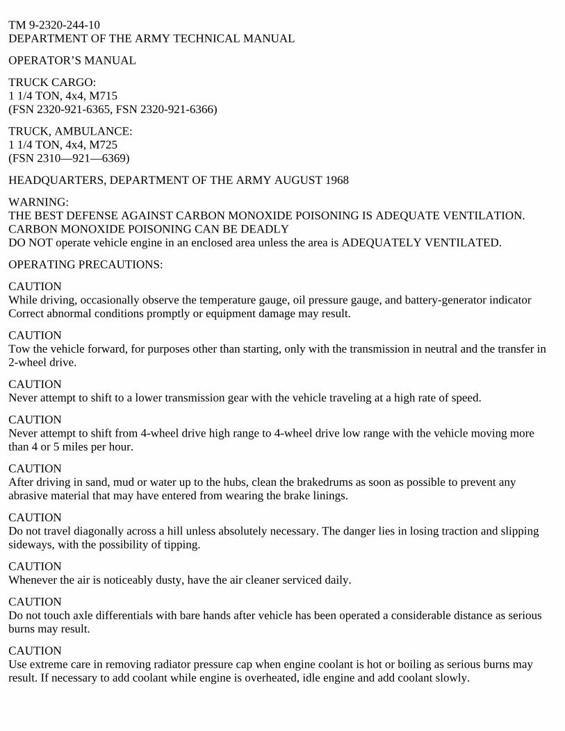
The vehicle serial number is stamped on a metal plate located at the center of the dashpanel.
Figure 1. Vehicle serial number.
ENGINE CODE NUMBER
The engine code number is stamped on the lower right front of the cylinder block just behind the ignitor.

Figure 2. Engine Code Number
INSTRUMENTS
GeneralThe operational instruments are conveniently grouped where they can be easily seen on the instrument panel. Eachof the gauges indicates a critical function of the vehicle and warns of impending trouble in advance. Knowing thefunction of these gauges and observing them occasionally while driving or while the engine is running can enableyou to prevent service problems that could result in expensive repairs.

Figure 3. Instrument cluster.
1. Fuel gauge2. Speedometer3. Temperature gauge4. Battery-generator indicator5. Instrument cluster light6. High beam indicator7. Oil pressure gauge
SpeedometerThe speedometer sweep hand indicates vehicle speed in miles per hour. The odometer registers accumulatedmileage traveled. The right-hand numeral of the odometer indicates tenths of a mile.
Oil Pressure GaugeThis gauge indicates the engine oil pressure when the engine is running. When the engine is started cold, the oilpressure may rise sharply, then recede to normal after the engine has warmed up. At idle speed the minimumindicated pressure should be 12 psi. At road speeds, the pressure gauge should indicate a minimum of 30 psi. If theindicated oil pressure is lower than these recommended minimums, stop the engine and investigate the cause of thislow oil pressure
Battery-Generator IndicatorThe battery-generator indicator located on the instrument cluster is marker BATTERY-GENERATOR. This gaugeindicates the charging activity of the charging system. The gauge should indicate GENERATOR (pointer in greenarc) when the engine is started, and continue to indicate charging activity as the engine speed is increaseddepending on the amount of electrical power being used. When the battery is supplying normal current, the pointershould indicate BATTERY (yellow arc). An abnormal discharge reading (pointer in red arc), with the enginerunning at normal speed, indicates a deficiency in the charging system.
Fuel GaugeThis gauge indicates how much fuel is in the fuel tank. The pointer drops to E (empty) when the ignition switch isturned off. It may take a moment for the gauge to indicate when the ignition switch is again turned on. It is normalfor the pointer to fluctuate at times when the vehicle is driven over rough terrain.
Temperature GaugeThe temperature gauge registers the temperature of the solution in the cooling system in degrees Fahrenheit.Operating temperature is normally between 170° F. and 190° F. Should the gauge register considerably higher, stopthe engine and determine the cause. Excessively low operating temperatures may indicate a faulty cooling system
Caution:Always remove the radiator cap slowly to avoid possible injury from escaping steam or hot water. Never add waterwhen the engine is overheated; allow the engine to cool first.
High Beam IndicatorThe high beam indicator light, located just below the speedometer, will glow when the headlights are on high beamand warn you that the headlights may be shining into the eyes of oncoming drivers. When the dimmer switch,located near the drivers left foot, is pushed once, the headlights switch hack to low beam and the indicator light willgo off.
SWITCHES AND CONTROLS
Ignition SwitchThe ignition switch located to the left of the instrument cluster, is a two-position ON-OFF lever-type. This switchmust be in the ON position to operate any of the electrical instruments or switches.
Starter SwitchThe starter switch, located to the right of the accelerator pedal, is operated by the drivers right foot. Push the switchhard enough to force the body against the seat back.
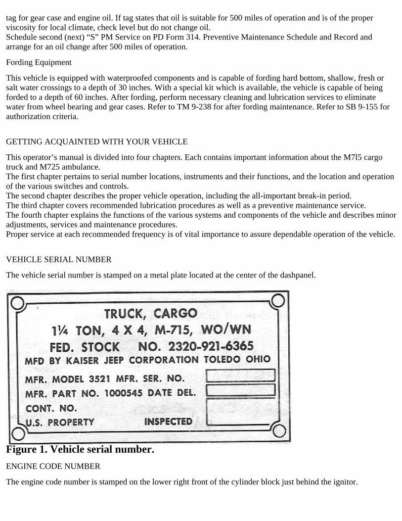
Light SwitchThe light switch, located to the right of the steering column, provides selective control of the various lightingcircuits by means of two switches; main switch and auxiliary switch. An unlock switch limits free movements ofthe main switch. The main switch has five positions: BO DRIVE, BO MARKER, OFF, STOPLIGHT, andSERVICE DRIVE. To move the main switch to any position except BO MARKER, the unlock switch must first bemoved to the UNLOCK position.The auxiliary switch has four positions: PARK, OFF, DIM, arid PANEL BRT. Movement of this switch is notrestricted by the unlock switch, but circuits under its control are dependent on the position of the main switch.
Figure 4. Main light switch
Dimmer SwitchThe dimmer switch, accessible to the driver's left foot, is used to raise or lower the headlight beams.
Turn Signal IndicatorThe turn signal lever is located on the left of the steering column. The UP position of the lever indicates a rightturn; the DOWN position, a left turn.A light in the indicator housing will flash if the lever is in either position. When the turn is completed, move theindicator lever back to the center position.

Figure 5. Switches and controls.
1 Windshield wiper controlvalve
12 Parking brake handle
2 warranty decal13 Transmission gear shiftlever
3 Driver instructions 14 Foot starter switch4 Left windshield wipermotor
15 Accelerator pedal
5 Main light switch 16 Choke6 instrument cluster 17 Ignition switch7 Right windshield wipermotor
18 Brake pedal
8 Identification and dataplates
19 Horn button
9 Safety rail 20 Clutch pedal10 Glove box 21 Headlight dimmer switch11 Transfer case shift levers 22 Directional signal switch
Windshield WipersThe windshield wiper control is located at the top left of upper windshield frame. The wipers may also be hand
operated by means of a lever, located on each wiper motor, in the event of vacuum failure.
Choke ControlThe manually operated choke control, located on the lower edge of the instrument panel to the right of the steeringcolumn, is used to assist in starting the engine during cold weather. (See Extreme Cold Weather Operation.)
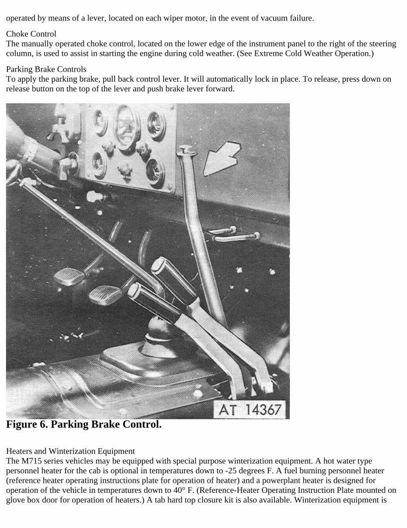
Parking Brake ControlsTo apply the parking brake, pull back control lever. It will automatically lock in place. To release, press down onrelease button on the top of the lever and push brake lever forward.
Figure 6. Parking Brake Control.
Heaters and Winterization EquipmentThe M715 series vehicles may be equipped with special purpose winterization equipment. A hot water typepersonnel heater for the cab is optional in temperatures down to -25 degrees F. A fuel burning personnel heater(reference heater operating instructions plate for operation of heater) and a powerplant heater is designed foroperation of the vehicle in temperatures down to 40° F. (Reference-Heater Operating Instruction Plate mounted onglove box door for operation of heaters.) A tab hard top closure kit is also available. Winterization equipment is

authorized under criteria of SB 9-16.
Figure 7. Heater controls.
1 Engine heater controls2 Personnel heater controls
Personnel Heater (-25 degrees F.)The controls for the hot water type personnel heater for the (‘all are located at the lower left corner of theinstrument panel. ‘With the air control knob pushed in, the heater system will not operate. Pull the knob out todirect outside air into the cab. Pull the defroster knob out to direct the air to the windshield. The temperature of theincoming air is controlled by the heater switch. Move the switch to the ON position for maximum air.

Figure 8. Personnel heater controls.
1 Decal-blower switch 2 Blower switch 3 instrument panel4 Defroster control knob5 Heat control knob6 Air control knob
Deep Water Fording SystemA deep water fording system is available for installation on the vehicle. The only control applicable to the operatoris the fording control handle. Pull the handle out before fording and push back in after leaving the water. Alsoinstall bell housing plug which is stored in the glove box. Remove plug after fording is completed. Plug should alsobe installed when driving in wet areas. Bell housing plug should he removed for draining during maintenanceoperation, so any oil accumulation will be removed.
Caution:When fording in depths over 42 inches, engine fan belts must be loosened to allow slippage of fan.
A visual pressure check of the deep water fording system may be made in the following manner:With the engine running and fording valve pulled out (valves closed) observe the gear shift lever boot. It. should

indicate a pressure build-up by blowing up into a ball and become hard to the touch. Shut off the engine and checkthe time for the pressure to completely leave the boot, that is, return to its original shape and be soft to the touch. Ifthis time is at least 30 seconds, the unit is operational. If the 30 seconds are not reached, check lines, fittings, andseals using a soap solution to find excessive leakage points and correct.
Seat AdjustmentThe seat adjustment control handle, located on the left side of the drivers seat, is lifted to unlock the seat foradjustment. The handle is locked by pushing down until it engages one of the adjustment notches in the seat.
Figure 9. Seat adjustment.
Hood LatchTwo hood latches, located on the front corners of the hood, are engaged to lock the hood in position. To unlock thelatches, lift latches until they are clear of their catches and turn slightly. The hood may now be raised.
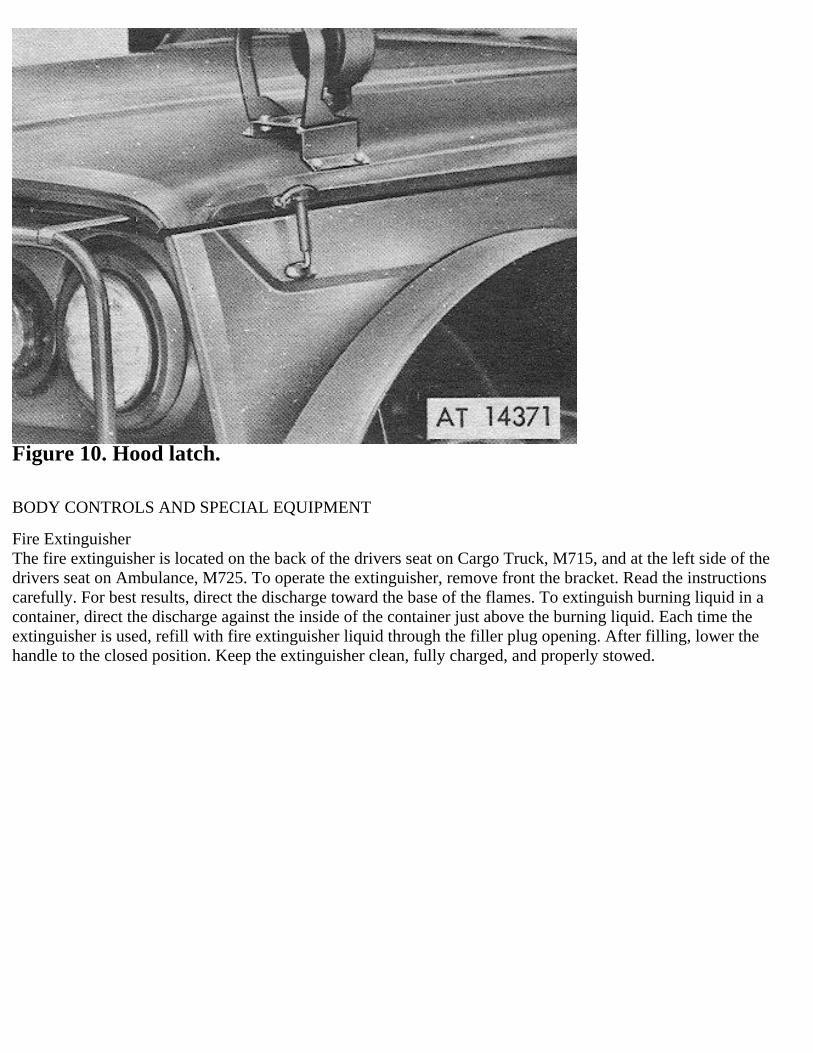
Figure 10. Hood latch.
BODY CONTROLS AND SPECIAL EQUIPMENT
Fire ExtinguisherThe fire extinguisher is located on the back of the drivers seat on Cargo Truck, M715, and at the left side of thedrivers seat on Ambulance, M725. To operate the extinguisher, remove front the bracket. Read the instructionscarefully. For best results, direct the discharge toward the base of the flames. To extinguish burning liquid in acontainer, direct the discharge against the inside of the container just above the burning liquid. Each time theextinguisher is used, refill with fire extinguisher liquid through the filler plug opening. After filling, lower thehandle to the closed position. Keep the extinguisher clean, fully charged, and properly stowed.
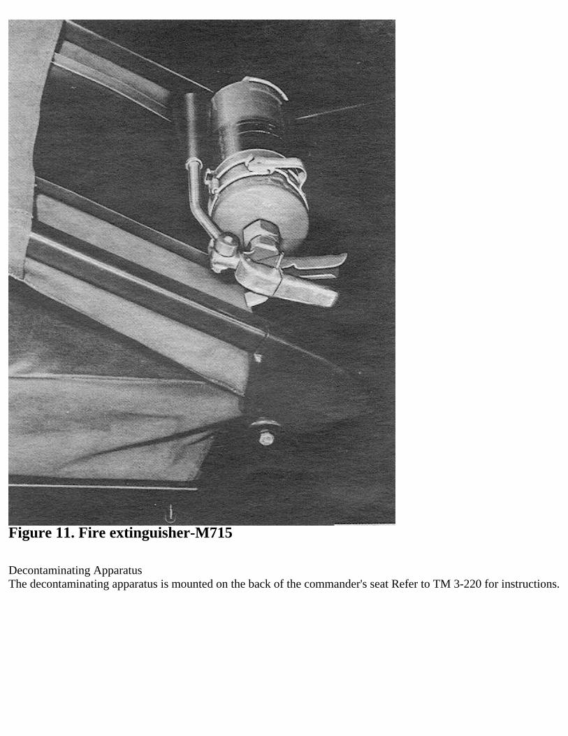
Figure 11. Fire extinguisher-M715
Decontaminating ApparatusThe decontaminating apparatus is mounted on the back of the commander's seat Refer to TM 3-220 for instructions.

Figure 12. Decontaminating apparatus.
Removing Cab Top and Lowering Windshield
The cab of the M 71 5 cargo truck is equipped with a folding windshield and a removable canvas top. Whenremoved, the paulin and its supporting members are stowed behind the cab seats. Removal and stowage proceduresare outlined below:1. Unbuckle the three straps securing the paulin to the inside rear of the cab. Release the eighteen fasteners securingthe paulin to the door window frame.2. Throw paulin over the windshield and pull paulin edge from windshield channel. Remove paulin from vehicleand fold. See figure 13.

Figure 13. Paulin over windshield.
3. Lift the two roof bows from their sockets and remove from vehicle.4. Remove the two door window frame-to-cab bolts and. the window frame-to-windshield bolt and nut from eachdoor window frames from the vehicle. Replace the bolts and nuts in cab and windshield for storage. See figure 14.
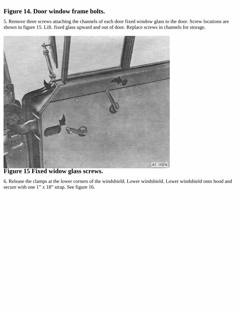
Figure 14. Door window frame bolts.
5. Remove three screws attaching the channels of each door fixed window glass to the door. Screw locations areshown in figure 15. Lift. fixed glass upward and out of door. Replace screws in channels for storage.
Figure 15 Fixed widow glass screws.
6. Release the clamps at the lower corners of the windshield. Lower windshield. Lower windshield onto hood andsecure with one 1” x 18” strap. See figure 16.

Figure 16. Windshield lowered.
7. Stow both door window frames under battery box and behind commander's seat with one 1’’ x 28” strap. Seefigure 18.8. Stow left door fixed window glass behind driver’s seat with two 1” x 39” straps. See figure 17.9. Stow right door fixed window glass behind commander’s seat with one 1” x 42” strap. See figure 18.10. Secure bows, frames and right window glass behind commander’s seat with one 1” x 45” strap.11. Secure bows behind driver’s seat with one 1” x 22” strap. See figure 18.12. Stow paulin behind commander’s seat.13. Once all items are stowed, it is recommended that all straps be checked to assure that they are tight and secure.
Installing Cab TopTo install the cab top, reverse the removal procedure given above.

Figure 17. Left fixed window stowed.
Figure 18, Right fixed window, frames and cab bows stowed

Power Ventilator Controls—Ambulance M725Two ventilator blowers are provided to draw hot air or odors from the patient compartment. Each blower motor iscontrolled by a switch. Openings in the blower ducts are controlled by the ventilator blower control valve handles.To operate either blower, turn the blower switch to the ON position. Turn the ventilator blower control valvehandles to the desired position to regulate the valve. When the valve handles are in the horizontal positions, thevalves are fully closed; when the handles are in the vertical position, the valves are fully open.
Surgical Lamp—Ambulance M725The surgical lamp is provided with a toggle switch to turn the lamp on or off. To direct the light beam, loosen theknurled thumb screw that secures the lamp in the shell and swing the lamp in the desired direction. When the lampis not in use, position it in the shell and tighten the thumb screw.
Dome Lamp—Ambulance M725The dome lamp, located in the top of the vehicle, is controlled by an ON-OFF toggle switch.
Spot Lamp—Ambulance M725The spot lamp is mounted on the roof of the drivers compartment. Controls are operated by the driver. To operate,push the spotlight switch forward. Turning the handle raises or lowers the light beam; revolving the handle moves itto the right or left.
Patient Compartment Heater—Ambulance M725The personnel heater for the patient compartment of the M725 ambulance is controlled by a heater control boxlocated on the inside wall of the compartment. The heater is located under the left front patient seat.To start the heater, move the HI-LO switch ‘to the Hi position and hold the heater switch in the START positionuntil the indicator lamp lights. When the indicator lights, snap the switch to RUN. Warm air should be felt at theheat outlet. The warm air output may be regulated by snapping the H I-LO switch from III to LO according to theheating requirement. To deflect the stream of heated air from the heater outlet, move the heat deflector handle tothe desired position.

Figure 19. Litters in position.
1 Litter2 Litter rack support bar3 Safety strap4 Litter rack (seat back) 5 Seat
Litters-Ambulance M725The interior of the ambulance body contains provisions for transporting seated or litter patients. Fight seatedpatients or five litter patients (two on seat rack, two on seat backrest rack when in raised position, one on floor), canbe accommodated.To raise seat backrest rack, first release the hold-down straps, securing lower ends of seat backrest-rack. Thenswing lower edge of rack upward until rack is in a horizontal position. Raise latch on inboard support bracket onforward wail and insert stud at end of rack into bracket. Push entire rack toward outer wail and lower latch to retainstud in bracket. Swing support bar on ceiling to a vertical position by releasing latch at forward end and sliding barforward to disengage stud. Engage keyhole slot in bar with stud on rack and lower latch against protruding stud.Rotate locking bar at rear outboard retainer loop to horizontal position.To lower rack for loading of litter, first pull out lifting handles at rear of rack and release rear inboard support barfrom stud on rack. Then raise locking bar over rear outboard retainer loop. Grasp lift handles, raise and swing rackinboard to disengage retainer loop from hinge bracket. Lower rear of rack until it rests on patient seat and engageswith retainer loop on retainer bracket on wall at rear. Litter is loaded at this position. With litter on rack, grasplifting handles, raise and swing rack outboard to engage retainer loop with hinge bracket. Engage rear inboardsupport bar with stud on rack and lower latch against stud. Lower locking bar over rear outboard retainer loop. Pushlifting handles in. Secure litter to rack with hold-down straps provided at both ends. Engage safety straps with loopson inboard edge of rack.
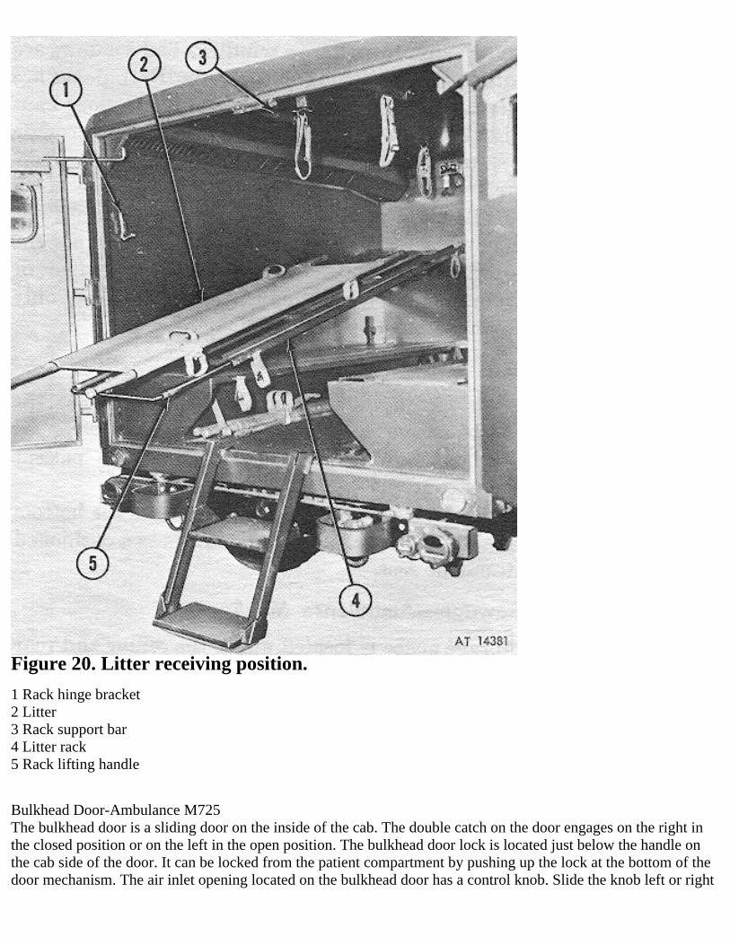
Figure 20. Litter receiving position.
1 Rack hinge bracket2 Litter3 Rack support bar4 Litter rack5 Rack lifting handle
Bulkhead Door-Ambulance M725The bulkhead door is a sliding door on the inside of the cab. The double catch on the door engages on the right inthe closed position or on the left in the open position. The bulkhead door lock is located just below the handle onthe cab side of the door. It can be locked from the patient compartment by pushing up the lock at the bottom of thedoor mechanism. The air inlet opening located on the bulkhead door has a control knob. Slide the knob left or right

to control airflow.
Rear Doors-Ambulance M725The double doors located at the rear of the patient compartment allow easy access in and out of the body. Bothdoors have a window. The windows are equipped with a blackout curtain. Both doors are weatherstripped and areequipped with door handles that operate top and bottom latches to provide a secure closure. The left door handlecan be operated only from the inside. The right door has a handle both inside and outside. The right rear door canbe locked by moving the lock catch on the inside before closing the door, or from inside after the door is closed.Use key only to unlock door from the outside.
Rear Step—Ambulance M725After opening the rear doors, the telescoping steps can be swung down into position at the center of the body,allowing easy access into the patient compartment.When folded up with the doors closed, the bottom side of the telescoping step doubles as a cushioned attendantseat.
Stowage—Ambulance M725Storage space is located under the center and rear seat cushions on both the right and left side of the patientcompartmentAn outside stowage compartment is located below and to the rear of the right side door. The recessed swivel handlehas a latch bar on the inside to keep it closed. Turn the handle to release the latch. A hasp is provided at the bottomfor a padlock.
Towing Shackles and Lifting LugsThe M715 truck series is equipped with four wheel lifting hugs into which towing shackles can be installed, andfour towing shackles which are also used as tiedowns. The tow and tiedown shackles are located two on the front ofthe vehicle extending through the front bumper, and two on the rear of the vehicle inside a bumperette at each end.When lifting the vehicle, the front and rear tow shackles are removed and installed into the wheel hub lug eye. Thetow shackles are equipped with a shackle pin drilled with a hole for a safety wire pin to be used as a retainer. Neveruse the tiedowns for lifting lest the vehicle frame be distorted.
OPERATION
PROPER BREAK-INBy taking reasonable precautions during the first few miles of driving and by giving the vehicle an opportunity toproperly “break-in”, operation and life of the working parts will be greatly improved.The drive train parts are precision fitted and close limits are maintained throughout. Therefore certain precautionsshould be observed to “break-in" the engine.For the first 50 miles avoid opening the throttle fully while accelerating or hill climbing.Keep under 50 miles per hour for the first 250 miles. Avoid full throttle accelerations.Occasionally lift your foot off the accelerator, if driving at steady speeds to improve engine lubrication duringbreak-in.After 250 miles, short periods at increasingly higher speeds are permissible. Step up speeds gradually as mileageaccumulates-operation at low speeds contributes little, if anything, to effective break-in.The crankcase should be drained at 500 miles and refilled with engine oil of the viscosity recommended in theLubrication Section. The oil filter should also be replaced at 500 miles.During the first 1,000 miles of operation be alert for any indications of over-heating in any component of thevehicle.
CARBON MONOXIDECarbon monoxide is a deadly gas. It has no odor, taste or color. It is in the exhaust fumes of all gasoline engines.Never start an engine in a closed garage. Always open the doors wide before starting the engine. Keep them openas long as the engine is running.

MAKING THE VEHICLE READY• Check the coolant level in the radiator.• Put gasoline in the fuel tank.• Check the oil level. (See Lubrication Section)• Give the vehicle a complete lubrication, covering all the items in the Lubrication Section.• See that all tires have the proper pressure.
STARTING THE ENGINE• Shift the transmission into Neutral.• Pull the choke control out halfway.• Turn the ignition switch on and push hard on the starter switch until the engine starts. If the engine fails to start in30 seconds, release the starter switch and wait about one minute before attempting to start the engine again.• If the engine fails to start in two or three attempts, consult the Troubleshooting Chart.• Set the choke control at the best position to keep the engine running for warmup. Push the choke all the way in assoon as the engine reaches operating temperature.
DRIVING THE VEHICLE• Release hand brake, if set.• Depress clutch pedal.• Move transmission gear shift lever to the first position. (Note that front axle and transfer case shift. levers are notused when the vehicle is driven on the highway in 2-wheel drive.)• Depress foot accelerator pedal gradually and at the same time slowly release clutch pedal.• Allow the vehicle to gain momentum (two or three vehicle lengths), then release the accelerator and depressclutch pedal at the same moment.• Move shift lever promptly to the next higher speed position. Depress foot accelerator pedal gradually and at thesame time slowly release the clutch pedal.• Shift to each of the next higher speeds in the same manner, releasing the accelerator and depressing the clutchpedal before moving the shift lever.
CHANGING TO LOWER SPEEDCaution: Never attempt to shift to a lower gear with the vehicle traveling at a high rate of speed.
• Depress clutch pedal.• Move gearshift lever quickly into the next lower speed, increasing the engine speed slightly if traveling on levelroad, and release clutch pedal.• It will be found advisable to make this change when the engine is placed under heavy pull or when dropping downto a very low speed, as when traveling up a steep grade, in sand, or in congested traffic.
REVERSING THE VEHICLE• With the vehicle at a standstill, depress the clutch pedal.• Shift the gearshift lever into the reverse position and slowly release clutch pedal while regulating the vehiclespeed with the foot accelerator.
TOWING THE VEHICLEThe vehicle may be towed forward in the normal manner without damage to the 4-wheel drive mechanism. Thegears in the transmission must be in neutral, and the gears in the transfer ease in 2-wheel drive.Should it be necessary, however, to lift the rear wheels and tow the vehicle in reverse, be sure to remove the frontaxle shaft driving flanges to prevent the front differential from rotating.Should the driving flanges be removed, a cover should be improvised to prevent dirt from entering the wheelbearings.

Figure 21. Shift pattern.
OPERATION UNDER UNUSUAL CONDITIONS
Refer to TM 21—300 and TM 21—305 for special driving instructions under unusual conditions.
Extreme Cold Weather OperationRefer to FM 31—70 and FM 31-71 for description of operation in extreme cold. Refer to TM 9-207 for operationand maintenance of automotive materiel in extreme cold (0° F. to —40° F.). Correct specific gravity reading ofbatteries exposed to extreme cold as outlined in TM 9—207. Also refer to TB ORI) 651 for instructions on use ofantifreeze solutions and cleaning compounds in engine cooling systems.For overnight or extended parking in temperatures at — 40 degrees F. or lower, overfill tires to 60 lbs. (size 9:00 x16) to reduce flat spots. Reduce pressure to normal before operating vehicle.If powerplant heater is not available, remove batteries and store in a warm place. It is not necessary to drain

subzero type engine oil, since it will remain fluid although unheated.
Extreme Hot Weather OperationContinuous operation at high speeds or under long hard pulls on steep grades, or soft terrain may cause the engineto overheat. Be alert for overheating and halt the vehicle for cooling off whenever necessary and tactical situationpermits. Make frequent inspections and servicing of the cooling system, engine oil filter, and carburetor air cleaner.If engine is consistently overheating, look for dust, sand, insects, or other obstructions in the radiator fins. Blow outany accumulations with compressed air or water under pressure. Flush cooling system if necessary. Avoid use ofwater containing alkali or other substances that may cause scale and rust formation. Use soft water wheneverpossible. Add corrosion-inhibiter compound to the coolant.In torrid zones check electrolyte level of batteries daily and replenish, if necessary, with pure distilled water. Ifdistilled water is not available, use rain or drinking water. Refer to TM 9-6140-20015 for dilution of electrolytewhen batteries are to be used in torrid climates.
Operating on Unusual TerrainObtain tire chains for operation on snow or ice-covered terrain or in deep mud.Lower tire pressure to travel over sand, ice, mud, and snow if tire chains are not available.
Caution: Do not lower tire pressure to extent that damage will result to tire. Restore to correct recommended tirepressure after emergency.
Front Mounted WinchThe M715 front mounted winch has a. 7,500 pound rated line pull at a minimum line speed of 15 feet per minute.The 150-foot wire rope is continuous in length with no splices and measures 7/16 inch in diameter. The rope isprovided with a clevis assembly and has an end chain measuring four feet in length. The winch can be engaged ordisengaged from the front bumper. The direction of rotation and the speed are controlled from the cab.Before operating, place the winch clutch shifter handle (located on the winch) in the engaged position. Thenoperate the shift lever in the cab in accordance with the instruction plate. The shift lever is on the floor to the rightof the driver’s seat.
TROUBLESHOOTINGNo adjustment should be made, or any parts tampered with, until the cause of the trouble is ascertained; otherwise,adjustments which are properly made may be altered. The trouble should first be analyzed.
Condition Possible cause See paragraph Possible cause See paragraph
Starting Motor WillNot Turn Engine Batteries discharged Batteries
Batteryconnections dirtyor loose
Batteries
Battery cablesdefective
Batteries
Battery cableconnections looseat ground starterswitch
Starting Motor
Wire connectionsloose at starterswitch, starting motorvoltage regulator, orignition switch
Starting MotorStarting motorinoperative
Starting Motor
Engine Fails ToStart No fuel Fuel Gauge
No fuel tocarburetor
Fuel System

Cylinder or manifoldflooded
Fuel SystemEngine needschoking
Starting theEngine
Plugged exhaustsystem
Exhaust System
Engine Stops Lack of fuel Fuel Gauge Lack of oilEngineLubrication
Disconnected ignitionwire
Ignition WiringCarburetorflooding
Fuel System andCarburetor
Engine overheated Cooling SystemDistributor breakerpoints dirty orpitted
Ignitor
Vapor lock Fuel System
Engine Misses atAll Speeds
Faulty ignitionwiring
Ignition Wiring Fouled spark plugs Spark Plugs
Spark plug pointsimproperly set
Spark PlugsSpark plugporcelains dirty
Spark Plugs
Distributor faulty Ignitor Water in fuel Fuel TankEngine overheated Cooling System
Popping BackThroughCarburetor
Dirt in carburetor Carburetor Water in fuel Fuel Tank
Spark plug wiresconnected toincorrect plugs.
Ignition Wiring
Engine Overheating Low engine oil levelEngineLubrication
Low coolant levelRadiator PressureCap
Fan belt slipping Fan BeltClogged radiatorcore
Radiator
Faulty thermostat Thermostat
Engine Misses atLow Speeds
Intermittent flow offuel
Fuel system andIgnitor
Poor ignition Spark Plugs,Ignition andWiring
Distributor pointimproperly adjustedor making poorcontact.
Ignitor Spark plug pointimproperly set.
Spark Plugs
Air leak at carburetorgasket
Carburetor
Loss of Power Lack of fuel Fuel System andFuel Pump
Carburetorflooding
Fuel System andFuel Pump
Engine overheated Cooling System Clutch slipping ClutchExhaust systemobstructed
Exhaust System

4-WHEEL DRIVE
What Is 4-Wheel Drive?All four wheels can exert driving force to the ground. A conventional vehicle is driven by the two rear wheelsalone. The front wheels are merely pushed along by the rear wheels. A 4-wheel drive vehicle is propelled by allfour wheels; the rear wheels are pushing and the front wheels are pulling. This gives four points of power andtraction.
How 4-Wheel Drive WorksEngine power is transmitted to all four wheels by using “live” front and rear axles. The front axle is driven by adrive shaft arid differential in the same manner as the rear axle. Power from the engine is delivered to thetransmission and transfer ease, which in turn drive both the front and rear wheels. The transfer case operates like asecond transmission. It gives you your choice of either 2 or 4-wheel drive and an auxiliary range low gear. Withauxiliary range low gear you have eight forward gear combinations.
Transfer CaseThe transfer ease front axle drive lever gives you your choice of 2-wheel or 4-wheel drive. In the forward positionyou are in 2-wheel drive. Move the lever to the rear Position for 4-wheel operation. The 4-wheel drive auxiliaryrange shift lever has two positions: low, and high. The rear position (low) gives you low-range 4-wheel drive forthe toughest going. The forward position (high) gives you high-range 4-wheel drive for less difficult situations.Positioning of the shift levers prevents shifting into low range, 2-wheel drive. This feature protects the rear axlefrom overload.
How To Shift GearsTo shift from 2-wheel drive to 4-wheel drive, let up on the accelerator if the vehicle is moving, and shift the front-axle drive lever to the rear position. This puts yon in 4-wheel drive high range and you operate the vehicle in theconventional manner. The auxiliary range lever must he in high position for all 2-wheel drive operations (fig. 22).

Figure 22. 2 wheel to 4 wheel drive.
To shift front 4-wheel drive high range to 4-wheel drive low range, bring the vehicle to a virtual standstill. Neverattempt to shift into low range with the vehicle moving more than 4 to 5 mph. Depress the clutch and move theauxiliary range lever to the rear (low) position. Release the clutch and proceed in the usual fashion. Your vehiclewill move at a slower ground speed with higher engine rpm. because of the lower gear. You can now select any ofthe standard transmission gears to meet your power requirements (fig. 23).
Figure 23. 4-wheel drive high range to 4-wheel drive low range.
To shift front 4-wheel drive low to 4-wheel drive high, depress the clutch and move the auxiliary-range lever to theforward (high) position. This can be done only at low vehicle speeds. Engage the clutch and proceed in 4-wheeldrive high range (fig. 24).
Figure 24. 4-wheel drive low to 4-wheel drive high.

To shift from 4-wheel drive to 2-wheel drive, let up on the accelerator if the vehicle is moving and move thefront-axle-drive lever to the forward position. The auxiliary range lever must be in high (forward) position beforethe front axle drive can be disengaged (fig. 25).
Figure 25. 4-wheel drive to 2-wheel drive.
When To Use 4-Wheel DriveUse 4-wheel drive to provide additional traction and lower gearing for difficult terrain and to provide low speedpulling power. You should only use 4-wheel drive when greater traction and power are required than can beprovided by the standard transmission low gear. Use 4-wheel drive off the road when you need it. Use it in snow.Use it to get heavy trailers rolling and for pulling heavy equipment. Use it on ice, hills, mud, sand, and wherevernormal 2-wheel drive traction won't do the job.
When Not To Use 4-Wheel DriveFor normal driving on hard-surfaced roads, 4-wheel drive should not be used. The additional tractive effort itprovides is not needed under such conditions. Prolonged use of 4-wheel drive on hard-surfaced roads mayoccasionally cause temporary difficulty in shifting out of 4-wheel drive. This condition is caused by a buildup oftorsional stress in the drive train and results from normal variations in tire diameters under different loadconditions. To relieve this buildup, simply drive the vehicle in reverse for several feet or drive off the hard surfacemomentarily to allow the tire to slip.
DRIVING TECHNIQUES IN 4-WHEEL DRIVE
Through Mud, Snow, and SandShift to 4-wheel drive, high range, first gear when going through mud, snow, and sand without a load. Auxiliarylow range is not necessary in such conditions unless a load is being pulled by the vehicle or unless it is desired toproceed more slowly because of changing road conditions. Don't shift into any lower gear than is necessary tomaintain headway. Try to keep a constant engine speed. Over-revving the engine will cause the wheels to startspinning and traction will be lost.

The tire pressures may be reduced to 10 psi. front, 15 psi. rear, with maximum speed of 5 mph.
Figure 26. 4 wheel drive, high range, first gear.
CAUTION-Through Sand, Mud, or Water.The vehicle may on occasion be driven up to the hubs in sand, mud, or water. As soon as possible thereafter, cleanthe braked drums to prevent any abrasive material that may have entered from wearing the brake linings.
UphillShift to 4-wheel drive, low range, second gear. Drop down to first gear only when it is apparent that the steepnessof the ascent requires the lower gear to maintain headway.Apply power smoothly. Don't lose traction by over-revving the engine. In certain conditions, headway can hemaintained by using a mild pumping action on the accelerator. This action produces engine speeds slightly aboveand below the vehicle speed and gives increased "bite"
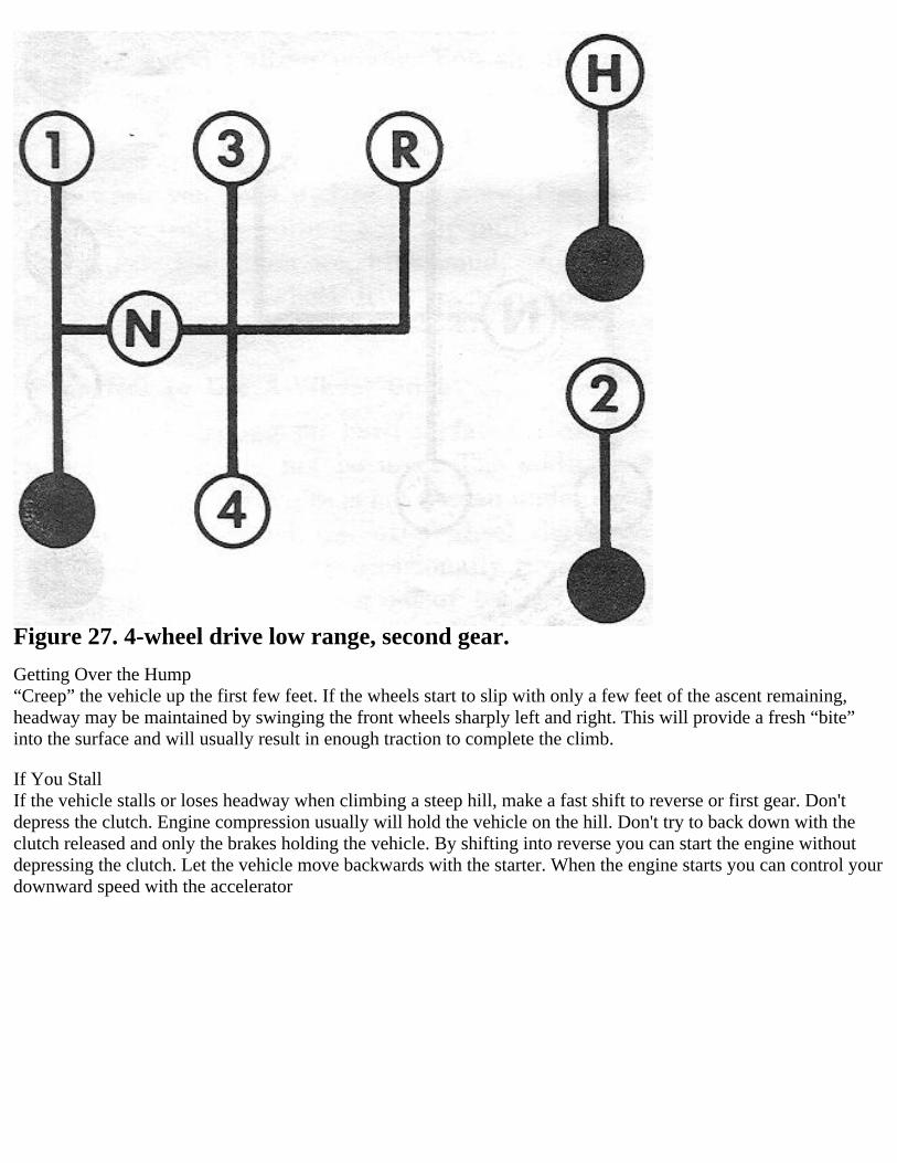
Figure 27. 4-wheel drive low range, second gear.
Getting Over the Hump“Creep” the vehicle up the first few feet. If the wheels start to slip with only a few feet of the ascent remaining,headway may be maintained by swinging the front wheels sharply left and right. This will provide a fresh “bite”into the surface and will usually result in enough traction to complete the climb.
If You StallIf the vehicle stalls or loses headway when climbing a steep hill, make a fast shift to reverse or first gear. Don'tdepress the clutch. Engine compression usually will hold the vehicle on the hill. Don't try to back down with theclutch released and only the brakes holding the vehicle. By shifting into reverse you can start the engine withoutdepressing the clutch. Let the vehicle move backwards with the starter. When the engine starts you can control yourdownward speed with the accelerator

Figure 28. 4-wheel drive. low range, reverse gear.
Downhill
Your 4-wheel drive vehicle can proceed in safety down a grade which could not be negotiated safely by aconventional 2-wheel drive vehicle. Shift to low range, first gear and let the vehicle go slowly down the hill with allfour wheels turning against engine compression. This will permit you to control the vehicle's speed and direction.

Figure 29. 4-wheel drive, low range, first gear.
Warning: Across slopes. Avoid this situation! Your vehicle will seldom encounter a hill which it cannot negotiatedirectly. However, natural obstacles may make it necessary to travel diagonally up or down the hill. The danger liesin losing traction and slipping sideways with the possibility of tipping.When necessary, choose as mild an angle as possible, keep moving, and make your turns quickly.WE REPEAT—DON’T TRAVEL DIAGONALLY ACROSS A HILL UNLESS ABSOLUTELY NECESSARY.
Safety and 4 Wheel DriveYour vehicle has sufficient power and traction to take you safely through conditions which would be hazardous orimpossible for conventional vehicles. A powerful, useful tool that will perform many difficult tasks, 4-wheel drivemust be used with common sense and caution. Don't take unnecessary risks and don't attempt the impossible.Knowledge of your vehicle and its abilities are your best insurance. Know your vehicle; use it wisely and you willenjoy safe, economical, and faithful service.
LUBRICATIONRegular application of high-grade lubricants when operating your vehicle is of vital importance because of thediversified type of service it performs. The amount of trouble-free service you receive will be in proportion to thecare given. The type of service performed determines the frequency of lubrication. The following pages give thelocation arid frequency of lubrication.Because of the importance of lubrication, detailed recommendations are given in the following paragraphs.
ENGINE LUBRICATION
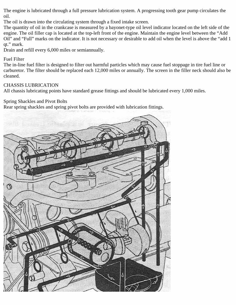
The engine is lubricated through a full pressure lubrication system. A progressing tooth gear pump circulates theoil.The oil is drawn into the circulating system through a fixed intake screen.The quantity of oil in the crankcase is measured by a bayonet-type oil level indicator located on the left side of theengine. The oil filler cap is located at the top-left front of the engine. Maintain the engine level between the “AddOil” and “Full” marks on the indicator. It is not necessary or desirable to add oil when the level is above the “add 1qt.” mark.Drain and refill every 6,000 miles or semiannually.
Fuel FilterThe in-line fuel filter is designed to filter out harmful particles which may cause fuel stoppage in tire fuel line orcarburetor. The filter should be replaced each 12,000 miles or annually. The screen in the filler neck should also becleaned.
CHASSIS LUBRICATIONAll chassis lubricating points have standard grease fittings and should be lubricated every 1,000 miles.
Spring Shackles and Pivot BoltsRear spring shackles and spring pivot bolts are provided with lubrication fittings.

Figure 30. Engine lubrication
OIL FILTER
Replace the oil filter at the end of the first 500 miles. Thereafter replace the element each 6,000 miles.Remove the oil filter by turning counterclockwise. Wipe the gasket area of the ‘base clean. To install a new filter,lightly coat gasket area with engine oil, screw on the filter unit until gasket contacts the engine, and then turnone-half turn more.HAND-tighten only; do not use tools.Start engine. Accelerate engine slightly and check oil pressure gauge to be sure normal oil pressure is indicated.Check the filter area for leaks.
The dry-type air cleaner is a plastic treated fiber type. Dust particles in the air entering the air cleaner are depositedon the pleated paper. This accumulated dust can choke of the air supply to tire carburetor if the element is notcleaned at regular intervals.Care of the air cleaner is extremely vital to the life of the engine. Pay particular attention to the amount of dust anddirt in the air taken into the engine through the air cleaner.To service the unit, first remove the element by unsnapping the three retaining clips from the top cover. Then tapthe element to remove accumulated dust. Reinstall the unit.Replace the element as required.When the dust is not noticeable in the air, service the air cleaner each 1,000 miles. Whenever the air is noticeablydusty (for example, when the vehicle is driven over dry dirt roads or cross country) service the air cleaner daily.
IgnitorEvery 6,000 miles or semiannually remove ignitor. Remove plug under nameplate and withdraw felt wick. Soakwick in engine oil. Fill plug opening with grease. Insert wick, remove excess grease and install plug. Wipe breakercam lightly with grease. Apply 1 to 2 drops engine oil to breaker arm pivot pin, operate arm once or twice andremove excess oil. Install ignitor.
Steering GearCheck tire lubricant level in tire steering gear housing every 1,000 miles to be sure that the lubricant is at the fillerplug opening level. Add lubricant as required.Replace filler plug.
Propeller ShaftsThe propeller shaft universal joints and slip joints are equipped with lubrication fittings. Lubricate U-joints every1,000 miles until lubricant is visible coming out each of tire four bearing seals.
Front Axle Steering KnucklesThe front axle steering knuckles are inclosed in housings which are filled with lubricant. Cheek each 1,000 miles tobe sure the housings are filled to plug level. Each 12,000 miles the axle shafts and universal joints should heremoved and thoroughly cleaned and the housings filled with fresh lubricant.
Wheel BearingsThe wheel bearings should be removed, thoroughly cleaned, checked and repacked every 12,000 miles.
BRAKE MASTER CYLINDER
Check the fluid level in the brake master cylinder every 1,000 miles. Clean the top of the filler cap and housingarea. Replenish the brake fluid to a level 1/2" below the top of the fill hole. Use hydraulic brake fluid withnon-petroleum base only. Replace and tighten filler cap.
TRANSMISSIONCheck the oil level every 1,000 miles by removing the fill plug located on the right side of the transmissionhousing. Lubricant should he level with fill hole. Add lubricant as required arid replace fill plug. Drain and refillevery 12,000 miles. Do not overfill, but allow excess oil to drain out.
Transfer CaseCheck the oil level every 1,000 miles by removing the fill plug located on the left side of the transfer case.Lubricant should be level with the filler plug Openings. Add lubricant as required and replace filler plug. Drain andfill each 12,000 miles.
DIFFERENTIALSCheck the level in the differential housings every 1,000 -miles. Lubricant should be level with the filler plugopenings. Add lubricant as required and replace filler plug. Drain and fill each 12,000 miles.
BodyAt each 6,000 miles use a greaseless lubricant sparingly on the door lock striker plates. At each 12,000 mileslubricate the following: door and window weatherstrips, door latch rotors; door, tailgate, and hood hinge pivots.
PARTS REQUIRING NO LUBRICATION
SpringsThe vehicle springs should not be lubricated. At assembly the leaves are coated with a long-lasting special lubricantdesigned to last the life of the springs. Spraying with the usual mixture of oil and kerosene has a tendency to washthis lubricant from between the leaves, making it necessary to relubricate often to eliminate squeaking.
Water Pump and ClutchThe water pump and clutch release bearings are prelubricated for life when manufactured and cannot berelubricated.
Starting MotorThe starting motor bearings are lubricated as assembly to last between normal rebuild periods.
AlternatorThe alternator bearings, lubricated at assembly, require no further lubrication.
Shock AbsorbersHydraulic direct-action shook absorbers are permanently sealed and require no periodic lubrication service. Shockabsorber mounting bushings are not to be lubricated.
MAINTENANCE
PREVENTIVE MAINTENANCE SERVICES
GeneralThe purpose of preventive-maintenance services is to detect first signs of electrical and mechanical failures ofassemblies in the vehicle, and to insure that appropriate corrective action is taken before expensive and timeconsuming repairs or replacements are required. The system of preventive-maintenance services is based onfrequent inspections and services accomplished by operators, company battalion, or regimental maintenancepersonnel under active supervision by all commanders and leaders.

ResponsibilityOperators and crew chiefs are charged with personal responsibility for assigned vehicles. Squad, section andplatoon leaders are charged with supervisory responsibility for vehicles pertaining to their commands. Unit andorganization commanders are required to insure that vehicles issued or assigned to their commands are properlymaintained in a serviceable condition, and that they are properly cared for and used.
IntervalsThe mileage that a vehicle travels is the principal criterion for the frequency of preventive-maintenance service.Operation under adverse conditions, such as extreme temperature, dust, or mud, may requirepreventive-maintenance services to be performed more frequently. Reduce intervals betweenpreventive-maintenance services when environmental conditions indicate the need. Do not extend intervals betweenpreventive-maintenance services, except when authorized to do so.
General Procedures for all Services and Inspectionsa. The following general procedures apply to operator’s preventive-maintenance services and to all inspections, andare just as important as the specific procedures.b. Inspections to see if items are in good condition, correctly assembled or stored, secure, not excessively worn, notleaking, and adequately lubricated apply to most items in the preventive-maintenance and inspection procedures.Any or all of these checks that are pertinent to any item (including supporting, attaching, or connecting members)will be performed automatically, as general procedures, in addition to army specific procedures given.(1) Inspection for good condition is usually visual inspection to determine if the unit is safe or serviceable. Goodcondition is explained further as meaning: Not bent or twisted, not chafed or burned, not broken or cracked, notbare or frayed, not dented or collapsed, not torn or cut, not deteriorated.(2) Inspection of a unit to see if it is correctly assembled or stored is usually a visual inspection to see if the unit isin its normal position in the vehicle and if all its parts are present and in their correct relative position.(3) Excessively worn is understood to mean worn beyond serviceable limits or likely to fail, if not replaced beforethe next scheduled inspection. Excessive wear of mating parts or linkage connections is usually evidenced by toomuch play (lash or lost motion). It includes illegibility as applied to markings, data and caution plates, and printedmatter.c. Where the instruction “tighten” appears in the procedures it means tighten with a wrench, even if the itemappears to be secure.d. Such expressions as "adjust if necessary” or "replace if necessary” are not used in the specific procedures. It isunderstood that whenever inspection reveals the need of adjustments, repairs, or replacements the necessary actionwill be taken.e. Any special cleaning instructions required for specific mechanisms or parts are contained in the pertinent section.General instructions are as follows:(1) Use drycleaning solvent or mineral spirits paint thinner to clean or’ wash grease or oil from ail parts of thevehicle.(2) A solution of one part grease-cleaning compound to four parts of drycleaning solvent or mineral spirits paintthinner may be used for dissolving grease and oil from engine block, chassis, amid other parts. Use cold water torinse off any solution which remains after cleaning.(3) After the parts are cleaned, rinse and dry them thoroughly. Apply a light grade of oil to all polished metalsurfaces to prevent rusting.(4) When authorized to install new parts, remove any preservative materials such as rust-preventive compound,protective grease etc.: prepare parts as required (oil seals etc.); and for those parts requiring lubrication, apply thelubricant prescribed in the lubrication order.f. General precautions in cleaning are as follows:(1) Drycleaning solvent or mineral spirits thinner is flammable and should not be used near an open flame. Fireextinguishers should he provided when this material is used. Use only in well ventilated places. Battery groundshould be disconnected and taped.(2) This cleaner evaporates quickly and has a drying effect on the skin. If used without gloves, it may cause cracks

in the skin and, in the ease on some individuals, a mild irritation or inflammation.(3) Avoid getting petroleum products, such as drycleaning solvent or mineral spirits paint thinner, engine fuels, orlubricants on rubber parts as they will deteriorate the rubber.
Warning: The use of diesel fuel oil, gasoline or benzene (benzol) for cleaning is prohibited.
g. Nameplates, caution plates, and instruction plates made of steel, rust rapidly. When plates are found in a rustycondition, they should be thoroughly cleaned and heavily coated with an application of clear lacquer.
Daily Preventive-Maintenance ServiceEach vehicle will be inspected and serviced by its assigned operator and crew each day that it is operated. Theservice is divided into three parts:a. Before-Operation Service This service is performed on the vehicle to ascertain whether the vehicle is ready foroperation and if conditions affecting the vehicle's readiness have changed since the last after-operation service.b. During-Operation Service. This service consists of detecting any unsatisfactory performance. While driving, thedriver or crew should be alert for any unusual noises or odors, abnormal instrument readings, steering irregularities,or any other indications of malfunction of the vehicle. Every operation should he considered a test and any unusualor unsatisfactory performance noted.c. After-Operation Service. This is the basic daily service for tactical vehicles. It consists of correcting, so far aspossible, any operating deficiencies. Thus the vehicle is prepared to operate at a moment’s notice.
Specific Procedures for OperatorFollow time procedures listed in table I, preventive maintenance checks and services, in the numerical order given.
Periodic InspectionProper maintenance demands that a thorough service inspection and lubrication be given each 1,000 miles ofoperation. Such an inspection consists of a careful road test and examination to locate and analyze any small faultsthat may have developed. The prompt correction of minor faults thus discovered will go far toward reducingmaintenance and delays in operation.
TABLE I. Preventitive Maintenance Check and Service
Interval andSequenceNumberBefore
operation
Interval andSequenceNumberDuring
operation
Interval andSequenceNumber
After operation
Items to be inspected Procedure
1 Oil and coolantCheck oil and coolantlevels. Check sparecontainers for contents.
2 23 Water pump, fan belts,and pulleys
Inspect pulleys and fanfor alignment and belt fortension. Inspect waterpump for leaks.
3 24 Engine compartment
Inspect enginecompartment forindications of fuel, engineoil, and water leaks. Lookunder the vehicle forindications of leakinggear oil or brake fluid.
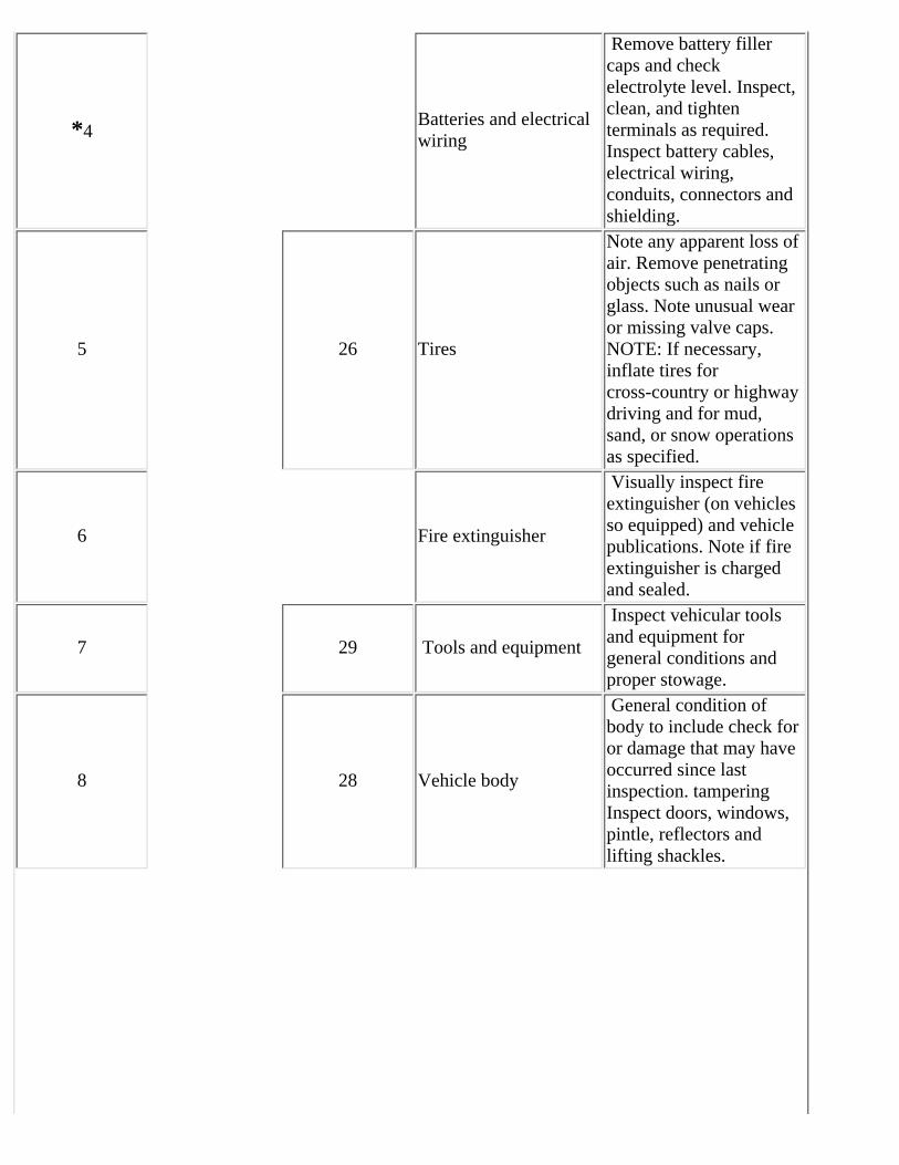
*4Batteries and electricalwiring
Remove battery fillercaps and checkelectrolyte level. Inspect,clean, and tightenterminals as required.Inspect battery cables,electrical wiring,conduits, connectors andshielding.
5 26 Tires
Note any apparent loss ofair. Remove penetratingobjects such as nails orglass. Note unusual wearor missing valve caps.NOTE: If necessary,inflate tires forcross-country or highwaydriving and for mud,sand, or snow operationsas specified.
6 Fire extinguisher
Visually inspect fireextinguisher (on vehiclesso equipped) and vehiclepublications. Note if fireextinguisher is chargedand sealed.
7 29 Tools and equipment
Inspect vehicular toolsand equipment forgeneral conditions andproper stowage.
8 28 Vehicle body
General condition ofbody to include check foror damage that may haveoccurred since lastinspection. tamperingInspect doors, windows,pintle, reflectors andlifting shackles.

9
Cab, doors, glass, topand frame, curtains andfasteners, seats andpaint.
Inspect cab or bodymountings, includingsprings. Test operation ofdoors, windows, hoodhinges and fasteners.Observe seat mountingsand upholstery. Inspectthe litter racks andoperation of personnelbeater (Ambulance TruckM725). Generally inspectbody, glass, panels, tops,fenders, running hoards,tailgate, chains, stakes,bows, paulins, andradiator and lamp guards.Examine condition ofpaint and legibility ofmarkings andidentification and cautionplates.
10 18Lights, horn, blowers,and heater.
If tactical situationpermits, operate horn andwindshield wipers.Inspect rear view mirrors.Check operation ofexterior lights and lightswitches. Note whetherthe head- lights appear tobe properly aimed. Notecondition of all lights and reflectors. Testthe spotlight switch andhandle for properoperation (AmbulanceTruck M725). Testoperation of surgicallight, dome light, blowersand heater (AmbulanceTruck M725).
11 19 22Service brake pedal andhand brake lever
Check service brake forproper pedal travel andhand brake for properadjustment. (Correctservice brake free travelis 1/2--inch). Seereferences for hand-brakeadjustments.

12Starter and starterswitch
With the ignition off,note if the starter switch,requires more thannormal pressure, and ifthe starter engagessmoothly without unusualnoise and turns the enginewith adequate crankingspeed. With ignitionswitch on, start engine. Caution: If there isexcessively low or noindications of engine oilpressure after a lime lapse(10 seconds max.) stopengine and determinecause.
13 20Engine: idle,acceleration, power,noise
In warming up engine,observe if the chokecontrol operatessatisfactorily. Note ifidling speed is correct.Listen for any unusualnoises at idle and higherspeeds. When operatingthe vehicle, note if it hasnormal power andacceleration in eachspeed range. Listen forany unusual noises whenthe engine is under load. Note. Investigate andcorrect any operatingdeficiencies as theyoccur, if beyond thescope of the driver, reportthem to individuals inauthority immediately.
14 21Exhaust pipe andmuffler
During engine warm up,listen for excessive orunusual noises and lookfor exhaust leaks.

27
Temperature of brakedrums, hubs, axles,transmission, transfer,differential. Immediatelyafter the road test, feelthese units cautiously.Warning: Full floatinghypoid axles operatequite hot. If lubricantlevels are correct and nounusual noises wereobserved during road test,assume axles arefunctioning properly. Donot touch hypoid axlewith bare hand aftervehicle has been operateda considerable distance,serious burns may result.An overheated wheel huband brake drum indicatesan improperly adjusted,defective or dry wheelbearing or a draggingbrake. An abnormallycool condition indicatesan inoperative brake. Anoverheated gear caseindicates lack oflubrication, adjustment,or defective parts.
25 Radiator and cap
Inspect radiator core forclogging with foreignmatter or if fins are bent.Check gasket in thepressure cap. Observecoolant level andexamine forcontamination. In coldweather, test coolant withhydrometer to see if itcontains sufficientantifreezeWarning: If it isnecessary to add coolantto the radiator whileengine is overheated, idleengine and add coolantslowly. Use extreme carein removing pressure cap

as serious burns mayresult.
30 Winch cableClean and oil winch cablein accordance with thecurrent lubrication order.
15 LubricateLubricate daily itemsspecified on lubricationorder.
16 31 Clean
Wash vehicle, cleaninside of cab, glass, andmirror. Clean engine andengine compartment asrequired.
17 32 Fuel Fill fuel tank asnecessary.
*Operations on batteries to be performed weekly.
FUEL SYSTEMThe fuel system consists of the fuel tank, fuel lines, fuel filter, fuel pump, carburetor, and air cleaner. Care andmaintenance of the air cleaner are covered in the lubrication section.The most important maintenance checks are to keep the system clean and free of water, and to periodically inspectfor leaks.Should the engine fail to start when cranked by the starting motor, the trouble may be in the fuel system. To locatethe trouble, first check the fuel gauge to be sure the fuel tank is not empty. If the fuel tank is not empty, checkfurther to see if fuel is reaching the carburetor. Disconnect the fuel line at the carburetor. Place a container underthe open lime and briefly crank the engine with the starting motor. If fuel spurts from the end of the line, the fuellines are clean and the fuel pump is operating properly.If no fuel leaves the disconnected fuel line, the trouble is in the fuel line, fuel filter, or fuel pump. Clean the fuelpump filtering screen and sediment chamber. (See Fuel Pump.) Cheek fuel lines for kinks or sharp bends. Checkfuel filter in line between pump and carburetor.If fuel is reaching the carburetor the cylinders or manifold may be flooded with fuel. Flooding may usually bedetected by a strong odor of fuel at the tail pipe or engine. Flooding is often, the result of excessive use of the chokecontrol while attempting to start the engine, or repeated operation of the accelerator pedal before attempting to startthe engine. To eliminate flooding push the choke control all the way in, hold the accelerator pedal all the waydown, and crank the engine with the starting motor.Should a hot engine stop, the trouble may be caused by vapor lock. ‘Vapor lock is the vaporization of the fuelbefore it enters the carburetor Allow the engine to cool, then restart it.Should the vehicle be stored for an extended period, the fuel system should first be completely drained and theengine started and allowed to run until the carburetor is emptied. This will avoid oxidation of the fuel, resulting inthe formation of gum in the units of the system.Gum formation is similar to hard varnish and can cause trouble. It may cause the fuel pump valves or the carburetorfloat valve to become stuck, or possibly block the filter screen. Gum formation can be dissolved by acetone or agood commercial fuel system solvent.In extreme cases, it will be necessary to disassemble and clean the fuel system however; one pint of acetone placedin the fuel tank with about one gallon of gasoline will usually dissolve any deposits as it passes through the systemwith the fuel.
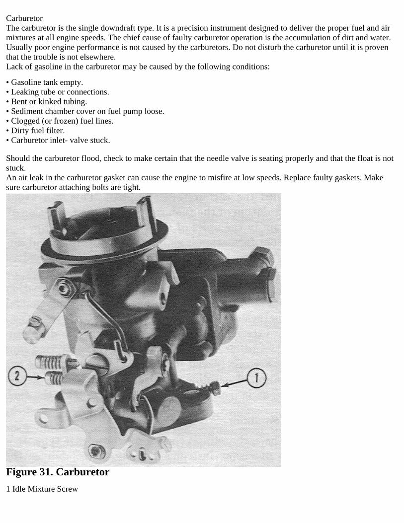
CarburetorThe carburetor is the single downdraft type. It is a precision instrument designed to deliver the proper fuel and airmixtures at all engine speeds. The chief cause of faulty carburetor operation is the accumulation of dirt and water.Usually poor engine performance is not caused by the carburetors. Do not disturb the carburetor until it is proventhat the trouble is not elsewhere.Lack of gasoline in the carburetor may be caused by the following conditions:
• Gasoline tank empty.• Leaking tube or connections.• Bent or kinked tubing.• Sediment chamber cover on fuel pump loose.• Clogged (or frozen) fuel lines.• Dirty fuel filter.• Carburetor inlet- valve stuck.
Should the carburetor flood, check to make certain that the needle valve is seating properly and that the float is notstuck.An air leak in the carburetor gasket can cause the engine to misfire at low speeds. Replace faulty gaskets. Makesure carburetor attaching bolts are tight.
Figure 31. Carburetor
1 Idle Mixture Screw
2 Idle Speed Screw
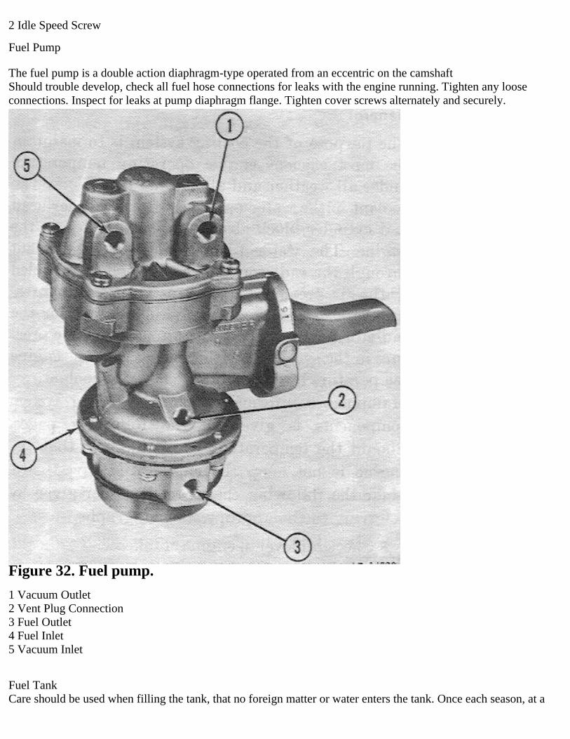
Fuel Pump
The fuel pump is a double action diaphragm-type operated from an eccentric on the camshaftShould trouble develop, check all fuel hose connections for leaks with the engine running. Tighten any looseconnections. Inspect for leaks at pump diaphragm flange. Tighten cover screws alternately and securely.
Figure 32. Fuel pump.
1 Vacuum Outlet2 Vent Plug Connection3 Fuel Outlet4 Fuel Inlet5 Vacuum Inlet
Fuel TankCare should be used when filling the tank, that no foreign matter or water enters the tank. Once each season, at a

time when the fuel supply is low in the tank, remove the drain plug in the bottom to drain out sediment and waterwhich will have accumulated.
Fuel ScreenThe fuel filler neck has a cone-shaped mesh fuel screen. This screen resists the passage of foreign matter into thefuel tank. Once each spring and fall remove the filter from the filler neck and clean the sediment from the filter.
EXHAUST SYSTEM
The exhaust system consists of the exhaust pipe, muffler, tail pipe, and support straps. Periodically check thesystem for dents, rust, and loose or broken support straps. A severe dent in any part of the system can cause loss ofengine power. Complete stoppage of the system, caused by a severe dent, or by a plugged tail pipe, can make theengine in operative.
COOLING SYSTEM
GeneralThe purpose of the cooling system is to maintain the most efficient engine operating temperature under all weatherand all driving conditions. The coolant in the water passages of the cylinder head and cylinder block absorbs heatgenerated in the engine. The water pump circulates the coolant through the radiator, where the coolant is cooled bythe air stream from the fan. The radiator pressure cap, in addition to providing a seal for the radiator filler neckopening, also controls the pressure in the system. The thermostat controls engine temperature by controlling theflow of coolant.Maintenance information on the cooling system components is given in the following pages. Should thetemperature gauge indicate that the engine is hot, stop the engine and investigate. Make the following checks in theorder given by referring to the appropriate paragraphs.
Check oil level in engine crankcase.Check coolant level.Check for slipping fan belt.Check for a clogged radiator.Check for a faulty thermostat.Check ignition timing.
RadiatorRadiator maintenance consists of keeping the exterior of the radiator core clean, the interior free from rust andscale, and the radiator free from leaks. The exterior of the radiator core should be cleaned and the radiator inspectedfor leaks each 1,000 miles of normal service. If the vehicle is subjected to considerable off-the-road operation, thisshould be performed more frequently.Cleaning should be performed by blowing out with air stream or water stream directed from the rear of the radiator.Visual inspection is not sufficient as the accumulation of small foreign particles on the core surfaces can restrictcooling without completely closing the core openings. Examine the radiator carefully for leaks before and aftercleaning.
Radiator HosesExamine radiator hoses spring and fall for possible need of replacement or tightening. Hoses that are collapsed,cracked, or indicate a soft condition on the inside should be replaced.When installing a hose, clean pipe connections and apply a thin layer of nonhardening sealing compound. Hoseclamps should he properly located over the connections to provide secure fastening. (The pressurized coolingsystem can blow off improperly installed hoses.)
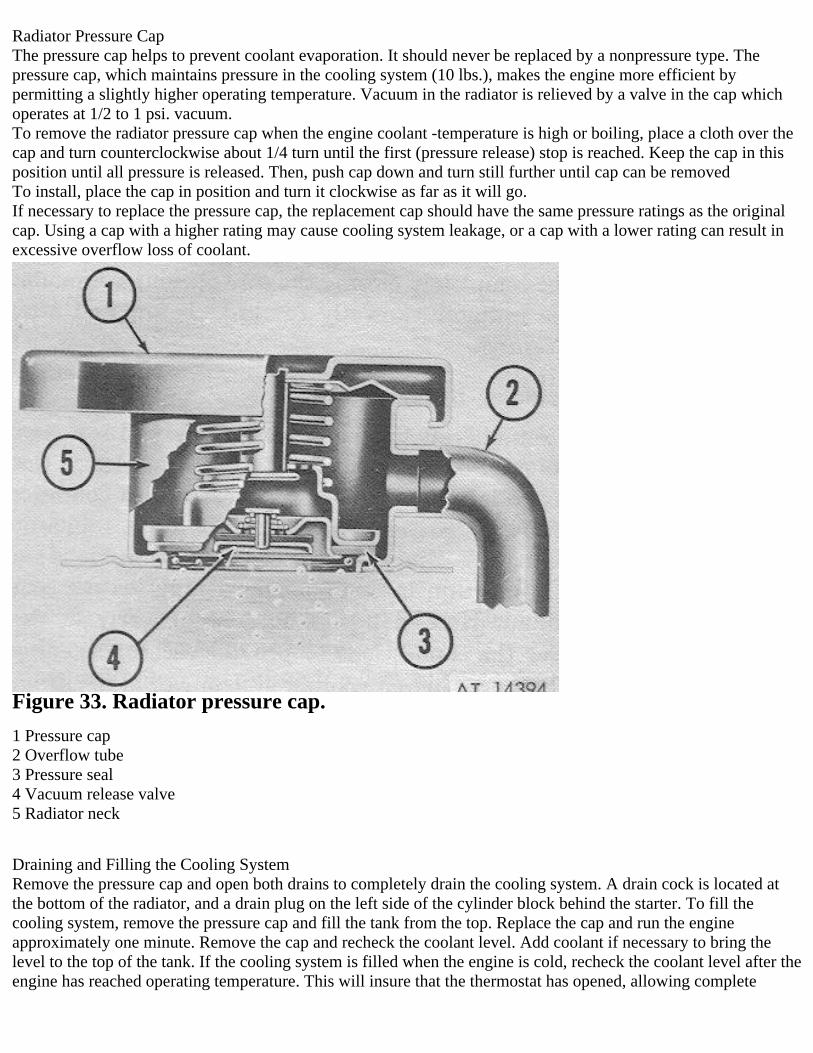
Radiator Pressure CapThe pressure cap helps to prevent coolant evaporation. It should never be replaced by a nonpressure type. Thepressure cap, which maintains pressure in the cooling system (10 lbs.), makes the engine more efficient bypermitting a slightly higher operating temperature. Vacuum in the radiator is relieved by a valve in the cap whichoperates at 1/2 to 1 psi. vacuum.To remove the radiator pressure cap when the engine coolant -temperature is high or boiling, place a cloth over thecap and turn counterclockwise about 1/4 turn until the first (pressure release) stop is reached. Keep the cap in thisposition until all pressure is released. Then, push cap down and turn still further until cap can be removedTo install, place the cap in position and turn it clockwise as far as it will go.If necessary to replace the pressure cap, the replacement cap should have the same pressure ratings as the originalcap. Using a cap with a higher rating may cause cooling system leakage, or a cap with a lower rating can result inexcessive overflow loss of coolant.
Figure 33. Radiator pressure cap.
1 Pressure cap2 Overflow tube3 Pressure seal4 Vacuum release valve5 Radiator neck
Draining and Filling the Cooling SystemRemove the pressure cap and open both drains to completely drain the cooling system. A drain cock is located atthe bottom of the radiator, and a drain plug on the left side of the cylinder block behind the starter. To fill thecooling system, remove the pressure cap and fill the tank from the top. Replace the cap and run the engineapproximately one minute. Remove the cap and recheck the coolant level. Add coolant if necessary to bring thelevel to the top of the tank. If the cooling system is filled when the engine is cold, recheck the coolant level after theengine has reached operating temperature. This will insure that the thermostat has opened, allowing complete

cooling system circulation.
ThermostatThe cooling system is designed to provide adequate cooling under most adverse conditions, however it is necessaryto employ some device to provide quick warming and to prevent overcooling during normal operation. Automaticcontrol of engine operating temperature is provided by a coolant flow control thermostat installed in the thermostathousing on top of the front end of the intake manifold. The thermostat is a heat-operated valve. It should always bein working order and the vehicle should never be driven without one installed, as there would then be no control ofengine temperature. The temperature at which the thermostat opens is preset and cannot be altered. If the thermostatis faulty, it must be replaced. Should sudden heating of the cooling system occur, the thermostat should be checkedfirst.
Water PumpThe water pump is mounted on the timing chain cover and is driven by V-belts. The water pump bearing acts as thecooling fan bearing, as the cooling fan is mounted on the water pump drive pulley and shaft. The impeller of thewater pump fits into a recess in the timing chain cover. It discharges coolant into the cylinder block through a portin the timing chain cover.The water pump is serviced only as a unit, if defective; the entire unit should be replaced.
Fan BeltsThe fan and alternator are driven by three matched V-belts. The drive of a V-belt is on the sides of the V. Fan beltstoo tight will cause rapid wear of the alternator and water- pump bearings, If loose, they may slip, preventing thewater pump or the alternator from operating properly.Inspect the fan belts for serviceability and proper tension.If necessary to replace one belt, then all three belts must be replaced, as they are a matched set.To replace the fan belts, loosen the clamp bolt on the alternator brace and swing the alternator toward the engineuntil sufficient clearance is obtained to install the new belts. Position the new belts over the fan pulley, over thecrankshaft pulley, then over the alternator pulley. Pull the alternator away from the engine until the belt tension isfirm. Tighten the clamp bolt and check the belt tension.
Cold Weather PrecautionsIn regions where winter temperatures can be expected to drop below 32 degrees F. precautions must be taken toprevent freezing of the coolant. Without the protection of sufficient antifreeze solution added, water in the coolingsystem will freeze and expand, possibly bursting the radiator and the cylinder block.It is important that the cooling system be made leakproof before installing any antifreeze solution. Be sure that hoseconnections are tight and that the hoses are in good condition. Should there be doubt regarding the condition ofeither, replace them.Immediately after adding antifreeze, run the engine a few moments to thoroughly mix the solution.
ELECTRICAL SYSTEM
GeneralThe major electrical systems are the starting system, ignition system, charging system, lighting system andelectrical instruments.The starting system cranks the engine. The starting switch activates the starting motor. The starting motor drivesthe engine flywheel.The ignition system furnishes the spark to the combustion chamber to ignite the fuel mixture. The ignition switchopens and closes the circuit. The igniter, composed of the ignition coil and distributor, combines the functions ofthese two components into a single unit. The ignition coil produces high secondary voltage while the distributormakes and breaks the primary circuit and distributes the high tension current in the secondary circuit.Spark plugs provide the spark to the combustion chamber. The high tension wiring is an important part of thissystem.

The charging system consists of the alternator, ignition switch, battery generator indicator, and two 12-voltbatteries hooked up in series to produce a 24-volt system. The batteries furnish current for starting the engine oroperating at idle speed. The alternator furnishes current (both to operate the other systems and to recharge thebatteries) at higher speeds.The lighting system consists of switches, lamp bulbs and their sockets and wiring. The lighting circuit is protectedby an overload circuit breaker.
BatteriesCaution: DUE TO THE CHARACTERISTICS OF AN ALTERNATOR, CHARGING CIRCUIT SERVICINGCAN BE DANGEROUS TO THE VEHICLE'S ELECTRICAL SYSTEM, THE ALTERNATOR ITSELF, ANDEVEN THE INDIVIDUAL, IF LEFT IN THE HANDS OF THE INEXPERIENCED WORKER.PARTICULARLY IMPORTANT IS THE POLARITY OF THE ALTERNATOR AND BATTERY: THATTHESE POLARITIES MATCH-UP, AND THAT ANY BOOSTER BATTERY OR BATTERY CHARGERATTACHED TO THE VEHICLE'S BATTERY BE ATTACHED POSITIVE TO POSITIVE AND NEGATIVETO NEGATIVE; OTHERWISE, THERE IS A DANGER OF BURNING OUT THE DIODES IN THEALTERNATOR OR THE WIRING.
The batteries, located between the driver’s and passenger's seats are secured in place by a two-piece holddownframe and four mounting bolts.Keep the battery terminals and cables clean and tight. A light coat of chassis lubricant applied at the terminals willreduce corrosion. Occasional cleansing around the terminals with a soda solution or ammonia will preventaccumulation of corrosive deposits. Do not allow grease, soda or ammonia to get into the battery cells. Keep thecell caps in place and sealed during the cleaning.Check the batteries every 1,000 miles with a hydrometer and at the same time check the electrolyte level in eachcell; add distilled water to maintain the solution level 3/8“ above the plates. Avoid overfilling and do not fail toreplace the filler caps and tighten securely. If the plates are exposed for any length of time, they can be seriouslydamaged; therefore, it is important to add enough water to keep the plates covered.A hydrometer reading of 1.275 indicates that the battery is fully charged. Should the reading fall below 1.235 it willbe necessary to recharge the battery or else use the lights and batteries sparingly until the batteries have had theopportunity to build up again.Should the engine not turn over when the ignition is tuned on and the starter is depressed, the batteries may bedischarged. If so, lights will be dim and the horn will have a weak tone or none at all.The engine also will not turn over if the battery cables are broken or defective or if the cable connections at thestarting motor solenoid or at ground are loose. Defective cables must be replaced; loose connections cleaned andtightened.
Warning: Do not allow flames or sparks to be brought near the vent openings of the batteries since hydrogen gas,produced in the course of the batteries normal operation in the vehicle, may be present in the batteries and mightexplode. The liquid in the batteries is a solution of sulphuric acid which, if accidentally spilled on the skin orspattered in the eyes should, as a first-aid measure, be flushed away promptly with quantities of clear water only.Seek medical aid if discomfort continues. If acid is spilled on the clothes, wet it thoroughly with a weak solution ofammonia, or with sodium bicarbonate or baking soda dissolved in water.
The rubber engine mountings partially insulate the engine from the frame. To assure a positive electricalconnection, a ground strap is provided from rear of transmission area to left frame side rail.The two attaching screws must be kept tight and the connections clean. A loose or poor connection may result inhard engine starting, low alternator charging rate, or sluggish operation of the starting motor.
AlternatorThe alternator produces a charging current Whenever the engine is operating, which should be sufficient tocontinuously charge the battery under normal electrical loads. The alternator has sealed bearings that require nolubrication, and will seldom need service except for an occasional check of the charging circuit.

Caution: DUE TO THE CHARACTERISTICS OF AN ALTERNATOR, CHARGING CIRCUIT SERVICINGCAN BE DANGEROUS TO THE VEHICLE'S ELECTRICAL SYSTEM, THE ALTERNATOR ITSELF, ANDEVEN THE INDIVIDUAL, IF LEFT IN THE HANDS OF THE INEXPERIENCED WORKER.PARTICULARLY IMPORTANT IS THE POLARITY OF THE ALTERNATOR AND BATTERY: THATTHESE POLARITIES MATCH-UP, AND THAT ANY BOOSTER BATTERY OR BATTERY CHARGERATTACHED TO THE VEHICLE'S BATTERY BE ATTACHED POSITIVE TO POSITIVE AND NEGATIVETO NEGATIVE; OTHERWISE, THERE IS A DANGER OF BURNING OUT THE DIODES IN THEALTERNATOR OR THE WIRING.
Ignition WiringThe ignition wiring includes the spark plug cables and wires between the distributor and ignition coil. Theconnections should be kept clean and tight. As the spark plug cables are completely waterproof and the distributorto coil wires are encased in the waterproof ignitor along with the distributor and coil, no maintenance should berequired.
IgnitorThe ignitor is composed of the ignition coil and distributor assembly contained in a common housing to ensure thewaterproof requirements of the electrical system. The distributor portion of the ignitor delivers the spark to theproper cylinder at the right time. It is operated by a coupling on the oil pump shaft. A mechanical breaker, built inthe distributor, opens ad closes the primary circuit. The spark advance is controlled by built-in centrifugal weights.The distributor cap should be kept clean for efficient operation. It should be inspected periodically for cracks,carbon runners, evidence of arcing and badly corroded high tension terminals. If any of these conditions exist, thecap should be replaced.
Spark PlugsSpark plugs in any vehicle are expendable. They require occasional examination, adjustment, cleaning, andeventual replacement. Old spark plugs reduce engine efficiency and economy. Replace them when inspectionindicates the old plugs cannot he reconditioned. It is recommended that spark plus be replaced every 12,000 miles.
Starting MotorThe starting motor is equipped with sealed-type bearings and requires no lubrication. The starting circuit should bechecked periodically. The starting circuit includes the starter switch and wires to the battery, and ignition switch.All connections should be clean and tight. Insulation on the wires should not be worn or damaged.If the starting motor will not turn the engine, although the light and horn operate properly, check the startingswitch. If the wiring is clean and tightly installed, the trouble is probably in the starter itself.
LIGHTING SYSTEM
GeneralThe lighting circuit is protected by an overload circuit breaker built into the switch and no replaceable fuse isrequired. It clicks on and off in the event, of a short circuit in the wiring.The upper and lower headlight beams are controlled by a foot switch located on the toe board at the left of theclutch pedal.
Blackout LightsThe blackout lighting system is controlled by the light switch and furnishes diffused low-intensity light. The systemis composed of the following components.• Blackout headlight located on the left front fender has sealed beam-type lamp unit.• Marker lights mounted adjacent to the service drive headlights. Three lamps in light housing are used for blackoutmarker, service parking, and signal lights.• Tail and stoplights mounted at rear of vehicle. Service of the blackout lights is limited to replacement of burnedout lamp units. Refer to Lamp Bulb Trade Numbers below, for the proper replacement lamps.
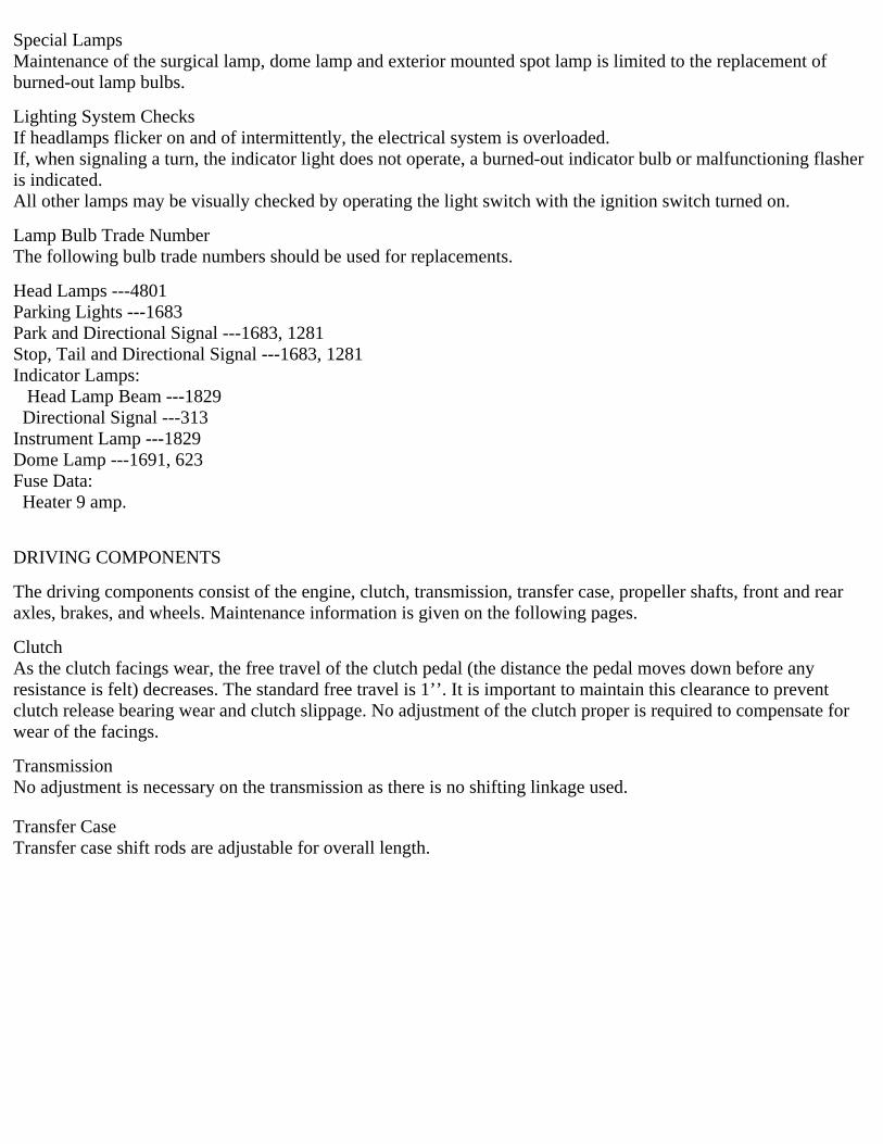
Special LampsMaintenance of the surgical lamp, dome lamp and exterior mounted spot lamp is limited to the replacement ofburned-out lamp bulbs.
Lighting System ChecksIf headlamps flicker on and of intermittently, the electrical system is overloaded.If, when signaling a turn, the indicator light does not operate, a burned-out indicator bulb or malfunctioning flasheris indicated.All other lamps may be visually checked by operating the light switch with the ignition switch turned on.
Lamp Bulb Trade NumberThe following bulb trade numbers should be used for replacements.
Head Lamps ---4801Parking Lights ---1683Park and Directional Signal ---1683, 1281Stop, Tail and Directional Signal ---1683, 1281Indicator Lamps: Head Lamp Beam ---1829 Directional Signal ---313Instrument Lamp ---1829Dome Lamp ---1691, 623Fuse Data: Heater 9 amp.
DRIVING COMPONENTS
The driving components consist of the engine, clutch, transmission, transfer case, propeller shafts, front and rearaxles, brakes, and wheels. Maintenance information is given on the following pages.
ClutchAs the clutch facings wear, the free travel of the clutch pedal (the distance the pedal moves down before anyresistance is felt) decreases. The standard free travel is 1’’. It is important to maintain this clearance to preventclutch release bearing wear and clutch slippage. No adjustment of the clutch proper is required to compensate forwear of the facings.
TransmissionNo adjustment is necessary on the transmission as there is no shifting linkage used.
Transfer CaseTransfer case shift rods are adjustable for overall length.
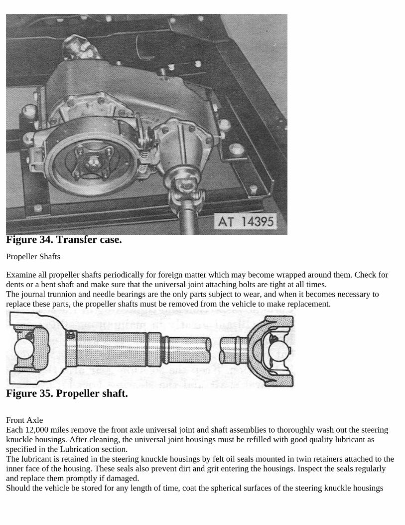
Figure 34. Transfer case.
Propeller Shafts
Examine all propeller shafts periodically for foreign matter which may become wrapped around them. Check fordents or a bent shaft and make sure that the universal joint attaching bolts are tight at all times.The journal trunnion and needle bearings are the only parts subject to wear, and when it becomes necessary toreplace these parts, the propeller shafts must be removed from the vehicle to make replacement.
Figure 35. Propeller shaft.
Front AxleEach 12,000 miles remove the front axle universal joint and shaft assemblies to thoroughly wash out the steeringknuckle housings. After cleaning, the universal joint housings must be refilled with good quality lubricant asspecified in the Lubrication section.The lubricant is retained in the steering knuckle housings by felt oil seals mounted in twin retainers attached to theinner face of the housing. These seals also prevent dirt and grit entering the housings. Inspect the seals regularlyand replace them promptly if damaged.Should the vehicle be stored for any length of time, coat the spherical surfaces of the steering knuckle housings

with light grease to prevent rusting.Should water enter the steering knuckle housing, it may be drained by removing the front inboard lower king pinbearing bolt.
Rear AxleThe rear axle requires little attention other than proper lubrication as specified in the Lubrication section.
STEERING SYSTEM
The crossover steering system requires little attention other than proper lubrication arid maintaining correctalignment.Looseness through the steering system will affect alignment. It is impossible to satisfactorily align the front wheelswithout first adjusting the various connections, including the front wheel bearings. Correct toe-in of the frontwheels is 3/32” to 5/23” which must be accurately measured for satisfactory front tire wear and steering. Toe in isadjusted by lengthening or shortening the steering tie rod. Periodic inspection and tightening of the steering partswill aid greatly in maintaining alignment. Keep the steering connecting rod ball joints snug but not tight; they mustoperate freely without lost motion. Keep the steering gear arm tight on the level shaft and the steering housingbracket tight on the frame.Do not tighten the steering gear to dampen out steering gear trouble.
BRAKES
The brakes are of the servo type, with star wheel adjustment.In operation, pressure is applied to the hydraulic fluid in the master cylinder through the foot pedal, forcing thefluid through the lines, and into the wheel cylinders. The pressure forces the pistons outward in the wheel cylinders,expanding the brakeshoes against the drums. As the pedal is further depressed, higher pressure is built up within thehydraulic system, causing the brake shoes to exert greater pressure against the drum.As the brake pedal is released, the brake, shoe return springs pull the shoes together forcing the fluid out of thecylinders and back into the lines toward the master cylinder.The hydraulic brake system must be bled whenever a fluid line is disconnected or air enters the system because oflow fluid level in the master cylinder reservoir. Air in the system will be indicated by a “spongy” pedal. Air trappedin the system is compressible and does not permit pressure, applied to the brake pedal, to be transmitted solidly tothe brake shoes.
Brake MaintenanceNo brake can be expected to work well when grease or oil is allowed to leak into the drum from the rear axle. Littlebraking friction can be obtained between the brakes and drums when the surface is covered with grease and oil. Forthis reason, take care not to overlubricate wheel bearings, forcing lubricant past seals. Also, check condition ofseals if leak is suspected or whenever brake drums are pulled.‘Whenever wheels are removed, it is advisable to wash the drums with a suitable solvent so that all grease and dirtare removed. Linings with any evidence of grease or oil on them should be replaced. The hydraulic system shouldbe kept free of dirt and moisture. It is advisable to drain the system and flush with pure alcohol once a year.
Caution: Keep mineral oils, gasoline, or kerosene out of the system, as they cause rubber cups to soften, swell, anddistort resulting in failure.
Parking BrakeThe external-type parking brake consists of a brake drum bolted to the transfer drive shaft rear companion flange,and an external contracting-type band mounted on the rear of the transfer. The band is connected to the parkingbrake lever by a mechanical linkage.Parking brake drums should be replaced if drum braking surface is worn, rough, scored or damaged. Brake liningsshould he replaced if the distance between the lining brake surface and the top of the rivet head is less than 1/32inch.

WHEELS AND TIRES
Mounting and Dismounting WheelsProcedure:Set hand brake. Block the wheels if on a grade.• To remove the spare tire from the rear underbody, loosen the bolt and move the slotted bracket to one side withthe vehicle wrench handle.• Place jack under front spring plate or the rear axle housing near wheel to be dismounted. Raise the jack until it isin contact with the front spring plate or the rear axle housing.• Loosen the wined nuts before raising vehicle.• Raise the vehicle until the tire is off the ground. Remove nuts and wheel.• When mounting the wheel on the vehicle, first place the wheel on the studs and replace the stud nuts. Tighten thenuts enough to hold the wheel in the proper position. Tighten stud nuts alternately and evenly to prevent wheelrun-out.• Lower the vehicle and remove the jack. Tighten the wheel nuts securely, to 300 pounds-feet maximum. Do notexceed this torque.
TiresTire pressure, tire rotation, wheel balance, and wheel alignment are the four vital factors that influence the extent oftire life and the ease and safety of vehicle control. Four common tire troubles are:• Excessive wear around the outer edges resulting from under-inflation.• Excessive wear in the center of the tread resulting from over-inflation.• Tire tread worn on one side indicating wheels need realigning.• Cuplike depressions on one side of the tread indicating wheels need balancing.The recommended tire pressures are as follows:25 psi. Front45 psi. RearThe importance of correct tire inflation cannot he over emphasized. To secure maximum tire life and most efficientvehicle operation, it is imperative that these pressures be maintained for all normal vehicle operation.Should unusual operating conditions require reduction in pressure, use care that tires are inflated to recommendedpressure immediately when normal operation is resumed.Valve caps should always be used. They should be free of dents and damaged threads. Valve caps protect valvecores by keeping out dust, dirt and moisture.Cross-switch the tires every 6,000 miles. This practice will even out differences in wear and make a set of tires lastlonger than they would without cross switching.Refer to figure 36 for the recommended rotation method for all tires. When a method of tire rotation is selected, itshould be used consistently or the full benefits of tire rotation may be lost.

Figure 36. Tire rotation.
Tire RemovalTo remove a tire from a semi-drop-center rim, first deflate the tire completely. Then force the tire away from therim throughout the entire circumference until the lock ring is loosened. Using the slot near the split in the lock ringas a starting point, spring the lock ring off the wheel rim with a suitable tool. Remove the tire from the ring andremove the inner tube. To install a tire, first drop the tire onto the rim. Then spring the lock ring over the wheel rimwith a suitable tool. For safety's sake, test the seating of the lock ring. Do this by first partially inflating the tire,then completely deflating the tire and checking the lock ring for proper seating. Then reinflate the tire to properpressure.
SUSPENSION
Springs and ShacklesThe springs should be periodically examined for broken or shifted leaves, loose or missing rebound clips, angle ofthe spring shackles and the position of the springs on the axle saddles. Springs with shifted leaves do not have theirnormal strength. Missing rebound clips may permit the leaves to fan out or break on rebound. Broken leaves maymake the vehicle hard to handle or permit the axle to shift out of line. Keep the spring attaching bolts tight.
Shock AbsorbersThe shock absorbers are not adjustable. Should squeaks occur in the bushings, add a flat washer on the mountingpins. DO NOT USE mineral oil to remove squeaks.
BODY
Paint CareRefer to introduction paragraph for instructions pertaining to paint care, methods, and material to be used.
DESTRUCTION OF MATERIAL TO PREVENT ENEMY USE
Destruction of the vehicles covered in this manual when subject to capture or abandonment in the combat zone, will
be undertaken by the using arm only when, in the judgment of the unit commander concerned, such action isnecessary in accordance with orders of, or policy established by, the Army Commander. When authorized,destruction can be accomplished by mechanical means, burning, demolition, or gunfire. In general, destruction ofessential parts, followed by burning will be sufficient to render the vehicles useless. Adequate destruction requiresthat all parts essential to the operation of the vehicles he destroyed beyond repair. In order to prevent repair by useof repair parts or cannibalization, destruction will be performed in the priorities established in the NATOStandardization Agreement 2113 (STANAG 2113) and will also include destruction of stocks of repair parts in thesame priority as when mounted on the vehicle. Destruction will be performed in the following priority.a. Carburetor/Fuel Pump/Distributor.b. Engine block and cooling system.c. Tires/Suspension.d. Mechanical or hydraulic systems.e. Differentials.f. Frame.By following the above priorities the same essential parts will be destroyed on all vehicles.