tm 9-2320-209-20-2-2 t.o. 36a12-1b-1092-1-2 9-2320-209-20-2-2.pdftm 9-2320-209-20-2-2 t.o....
TRANSCRIPT
T M 9 - 2 3 2 0 - 2 0 9 - 2 0 - 2 - 2
T . O . 3 6 A 1 2 - 1 B - 1 0 9 2 - 1 - 2
TECHNICAL MANUAL
VOLUME 2 OF 3
PART 2 OF 2
TROUBLESHOOTING
ORGANIZATIONAL LEVEL
21/2-TON, 6X6, M44A1 AND M44A2 SERIES TRUCKS
(MULTIFUEL)
TRUCK, CARGO: M35A1,
M35A2, M35A2C, M36A2; TRUCK,
TANK, FUEL: M49A1C, M49A2C; TRUCK, TANK,
WATER: M50A1, M50A2, M50A3; TRUCK, VAN,
SHOP: M109A2, M109A3; TRUCK, REPAIR SHOP:
M185A2, M185A3; TRUCK, TRACTOR: M275A1,
M275A2; TRUCK, DUMP: M342A2; TRUCK,
MAINTENANCE PIPELINE CONSTRUCTION:
M756A2; TRUCK, MAINTENANCE,
EARTH BORING AND POLESETTING: M764
D E P A R T M E N T S O F T H E A R M Y A N D T H E A I R F O R C E
M A Y 1 9 8 1
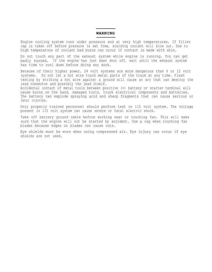
WARNING
Engine cooling system runs under pressure and at very high temperatures. If fillercap is taken off before pressure is set free, scalding coolant will blow out. Due tohigh temperature of coolant bad burns can occur if contact is made with skin.
Do not touch any part of the exhaust system while engine is running. You can getbadly burned. If the engine has just been shut off, wait until the exhaust systemhas time to cool down before doing any work.
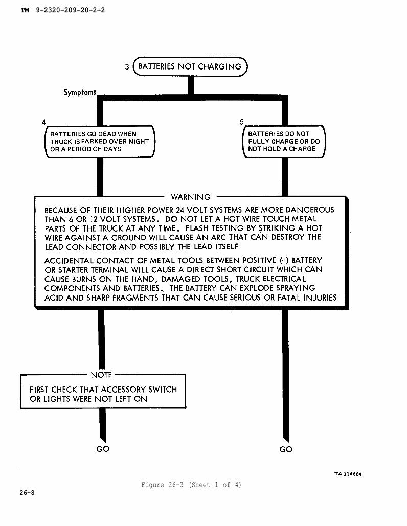
Because of their higher power, 24 volt systems are more dangerous than 6 or 12 voltsystems. Do not let a hot wire touch metal parts of the truck at any time. Flashtesting by striking a hot wire against a ground will cause an arc that can destroy thelead connector and possibly the lead itself.Accidental contact of metal tools between positive (+) battery or starter terminal willcause burns on the hand, damaged tools, truck electrical components and batteries.The battery can explode spraying acid and sharp fragments that can cause serious orfatal injuries.
Only properly trained personnel should perform test on 115 volt system. The voltagepresent in 115 volt system can cause severe or fatal electric shock.
Take off battery ground cable before working near or touching fan. This will makesure that the engine will not be started by accident. Use a rag when touching fanblades because edges on blades can cause cuts.
Eye shields must be worn when using compressed air. Eye injury can occur if eyeshields are not used.
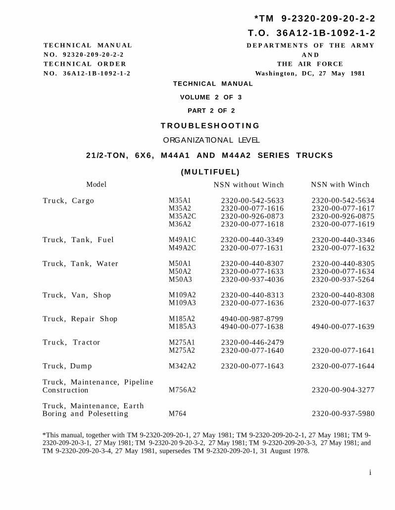
*TM 9-2320-209-20-2-2
T .O. 36A12-1B-1092-1-2TECHNICAL MANUAL DEPARTMENTS OF THE ARMYNO. 92320-209-20-2-2 ANDTECHNICAL ORDER THE AIR FORCENO. 36A12-1B-1092-1-2 Washington, DC, 27 May 1981
TECHNICAL MANUAL
VOLUME 2 OF 3
PART 2 OF 2
TROUBLESHOOTING
ORGANIZATIONAL LEVEL
21/2-TON, 6X6, M44A1 AND M44A2 SERIES TRUCKS
Model
Truck, Cargo
Truck, Tank, Fuel
Truck, Tank, Water
Truck, Van, Shop
Truck, Repair Shop
Truck, Tractor
Truck, Dump
Truck, Maintenance, PipelineConstruction
Truck, Maintenance, EarthBoring and Polesetting
(MULTIFUEL)
NSN without Winch
M35A1 2320-00-542-5633M35A2 2320-00-077-1616M35A2C 2320-00-926-0873M36A2 2320-00-077-1618
M49A1C 2320-00-440-3349M49A2C 2320-00-077-1631
M50A1 2320-00-440-8307M50A2 2320-00-077-1633M50A3 2320-00-937-4036
M109A2 2320-00-440-8313M109A3 2320-00-077-1636
M185A2 4940-00-987-8799M185A3 4940-00-077-1638
M275A1 2320-00-446-2479M275A2 2320-00-077-1640
M342A2 2320-00-077-1643
M756A2
M764
NSN with Winch
2320-00-542-56342320-00-077-16172320-00-926-08752320-00-077-1619
2320-00-440-33462320-00-077-1632
2320-00-440-83052320-00-077-16342320-00-937-5264
2320-00-440-83082320-00-077-1637
4940-00-077-1639
2320-00-077-1641
2320-00-077-1644
2320-00-904-3277
2320-00-937-5980
*This manual, together with TM 9-2320-209-20-1, 27 May 1981; TM 9-2320-209-20-2-1, 27 May 1981; TM 9-2320-209-20-3-1, 27 May 1981; TM 9-2320-20 9-20-3-2, 27 May 1981; TM 9-2320-209-20-3-3, 27 May 1981; andTM 9-2320-209-20-3-4, 27 May 1981, supersedes TM 9-2320-209-20-1, 31 August 1978.
i
TM 9-2320-209-20-2-2
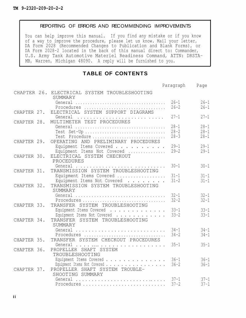
REPORTING OF ERRORS AND RECOMMENDING IMPROVEMENTS
You can help improve this manual. If you find any mistake or if you knowof a way to improve the procedure, please let us know. Mail your letter,DA Form 2028 (Recommended Changes to Publication and Blank Forms), orDA Form 2028-2 located in the back of this manual direct to: Commander,U.S. Army Tank Automotive Materiel Readiness Command, ATTN: DRSTA-MB, Warren, Michigan 48090. A reply will be furnished to you.
TABLE OF CONTENTS
Paragraph Page
CHAPTER 26. ELECTRICAL SYSTEM TROUBLESHOOTINGSUMMARY
CHAPTER 27.
CHAPTER 28.
CHAPTER 29.
CHAPTER 30.
CHAPTER 31.
CHAPTER 32.
CHAPTER 33.
CHAPTER 34.
CHAPTER 35.
CHAPTER 36.
CHAPTER 37.
i i
General . . . . . . . . . . . . . . . . . . . . . . . . . . . . . . . . . . . . .Procedures . . . . . . . . . . . . . . . . . . . . . . . . . . . . . . . . .
ELECTRICAL SYSTEM SUPPORT DIAGRAMSGeneral . . . . . . . . . . . . . . . . . . . . . . . . . . .
MULTIMETER TEST PROCEDURESGeneral . . . . . . . . . . . . . . . . . . . . . . . . . . . . . . . . . . . . .Test Set-Up . . . . . . . . . . . . . . . . . . . . . . . . . . . . . . . . .Test Procedure . . . . . . . . . . . . . . . . . . . . . . . . . . . . . .
OPERATING AND PRELIMINARY PROCEDURESEquipment Items Covered . . . . . . . . . .Equipment Items Not Covered . . . . . . . . . . . . . . .
ELECTRICAL SYSTEM CHECKOUTPROCEDURESGeneral . . . . . . . . . . . . . . . . . . . . . . . . . . . .
TRANSMISSION SYSTEM TROUBLESHOOTINGEquipment Items Covered . . . . . . . . . . . . . . . . . .Equipment Items Not Covered . . . . . . . .
TRANSMISSION SYSTEM TROUBLESHOOTINGSUMMARYGeneral . . . . . . . . . . . . . . . . . . . . . . . . . . . . . . . . . .Procedures . . . . . . . . . . . . . . . . . . . . . . . . . . . . . . . . . .
TRANSFER SYSTEM TROUBLESHOOTINGEquipment Items Covered . . . . . . . . . . . . .Equipment Items Not Covered . . . . . . . . . . . .
TRANSFER SYSTEM TROUBLESHOOTINGSUMMARYGeneral . . . . . . . . . . . . . . . . . . . . . . . . . . . .Procedures . . . . . . . . . . . . . . . . . . . . . . . . . . . . . . . . .
TRANSFER SYSTEM CHECKOUT PROCEDURESGeneral . . . . .... . . . . . . . . . . . . . . . . .
PROPELLER SHAFT SYSTEMTROUBLESHOOTINGEquipment Items Covered . . . . . . . . . . . . . .Equipment Items Not Covered . . . . . . . . . . . . . . . .
PROPELLER SHAFT SYSTEM TROUBLE-SHOOTING SUMMARYGeneral . . . . . . . . . . . . . . . . . . . . . . . .. . . . .Procedures . . . . . . . . . . . . . . . . . . . . . . . . . . . .
26-126-2
27-1
28-128-228-3
29-129-2
30-1
31-131-2
32-132-2
33-133-2
34-134-2
35-1
36-136-2
37-137-2
26-126-1
27-1
28-128-128-1
29-129-1
30-1
31-131-1
32-132-1
33-133-1
34-134-1
35-1
36-136-1
37-137-1

TM 9-2320-209-20-2-2
TABLE OF CONTENTS-CONT
CHAPTER 38.
CHAPTER 39.
CHAPTER 40.
CHAPTER 41.
CHAPTER 42.
CHAPTER 43.
CHAPTER 44.
CHAPTER 45.
CHAPTER 46.
CHAPTER 47.
CHAPTER 48.
CHAPTER 49.
CHAPTER 50.
CHAPTER 51.
CHAPTER 52.
CHAPTER 53.
CHAPTER 54.
Paragraph
PROPELLER SHAFT SYSTEM SUPPORTDIAGRAMSGeneral . . . . . . . . . . . . . . . . . . . . . . . . . . . . . . . . . . . . . 38-1
FRONT AXLE SYSTEM TROUBLESHOOTINGEquipment Items Covered . . . . . . . . . . . . . . . . . . . . . 39-1Equipment Items Not Covered . . . . . . . . . . . . . . . 39-2
FRONT AXLE SYSTEM TROUBLESHOOTING SUMMARYGeneral . . . . . . . . . . . . . . . . . . . . . . . . . . . . . . . . . . . . . .Procedures . . . . . . . . . . . . . . . . . . . . . . . . . . . . . . . . .
FRONT AXLE SYSTEM CHECKOUT PROCEDURESGeneral . . . . . . . . . . . . . . . . . . . . . . . . . . . . . . . . . . . .
REAR AXLE SYSTEM TROUBLESHOOTINGEquipment Items Covered . . . . . . . . . . . . . . . .Equipment Items Not Covered . . . . . . . . . . . . . . .
REAR AXLE SYSTEM SUPPORT DIAGRAMSGeneral . . . . . . . . . . . . . . . . . . . . . . . . . . . . . . . . . . . . .
BRAKE SYSTEM TROUBLESHOOTINGEquipment Items Covered . . . . . . . . . . . . . . . .Equipment Items Not Covered . . . . . . . . . . . . . . . .
BRAKE SYSTEM TROUBLESHOOTING SUMMARYGeneral . . . . . . . . . . . . . . . . . . . . . . . . .Procedures . . . . . . . . . . . . . . . . . . . . . . . . . . . . . . . . . .
BRAKE SYSTEM SUPPORT DIAGRAMSGeneral . . . . . . . . . . . . . . . . . . . . . . . .
HANDBRAKE SUBSYSTEM TROUBLESHOOTINGEquipment Items Covered . . . . . . . . . . . . . . . .Equipment Items Not Covered . . . . . . . . . . . . . .
COMPRESSED AIR SUBSYSTEMTROUBLESHOOTINGEquipment Items Covered . . . . . . . . . . . . . . .Equipment Items Not Covered . . . . . . . . . . . .
BRAKE SYSTEM TEST PROCEDURESGeneral . . . . . . . . . . . . . . . . . . . . . . . . . . . . . . . . . . . . .Test Set-Up . . . . . . . . . . . . . . . . . . . . . . . . . . . . . . . . .Test Procedure . . . . . . . . . . . . . . . . . . . .
BRAKE SYSTEM CHECKOUT PROCEDURESGeneral . . . . . . . . . . . . . . . . . . . . . . . . . .
WHEEL SYSTEM TROUBLESHOOTINGEquipment Items Covered . . . . . . . . . . . . . . . .Equipment Items Not Covered . . . . . . . . . . . . . . . .
STEERING SYSTEM TROUBLESHOOTINGEquipment Items Covered . . . . . . . . . . . . . . .Equipment Items Not Covered . . . . . . . . . . . . . . . .
STEERING SYSTEM TROUBLESHOOTING SUMMARYGeneral . . . . . . . . . . . . . . . . . . . . . . . . .Procedures . . . . . . . . . . . . . . . . . . . . . .
STEERING SYSTEM SUPPORT DIAGRAMSGeneral . . . . . . . . . . . . . . . . . . . . . . . . . . . . . . . .
40-140-2
41-1
42-142-2
43-1
44-144-2
45-145-2
46-1
47-147-2
48-148-2
49-149-249-3
50-1
51-151-2
52-152-2
53-153-2
54-1
Page
38-1
39-139-1
40-140-1
41-1
42-142-1
43-1
44-144-1
45-145-1
46-1
47-147-1
48-148-1
49-149-149-1
50-1
51-151-1
52-152-1
53-153-1
54-1
iii
TM 9-2320-209-20-2-2
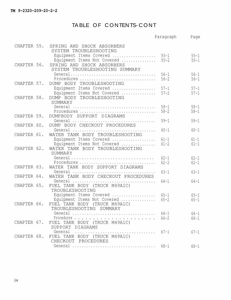
CHAPTER 55.
CHAPTER 56.
CHAPTER 57.
CHAPTER 58.
CHAPTER 59.
CHAPTER 60.
CHAPTER 61.
CHAPTER 62.
CHAPTER 63.
CHAPTER 64.
CHAPTER 65.
CHAPTER 66.
CHAPTER 67.
CHAPTER 68.
TABLE OF CONTENTS-CONT
Paragraph
SPRING AND SHOCK ABSORBERSSYSTEM TROUBLESHOOTINGEquipment Items Covered . . . . . . . . . . . . . . . . . . .Equipment Items Not Covered . . . . . . . . . . . . . . .
SPRING AND SHOCK ABSORBERSSYSTEM TROUBLESHOOTING SUMMARYGeneral . . . . . . . . . . . . . . . . . . . . . . . . . . . . . . . . . . . . .Procedures . . . . . . . . . . . . . . . . . . . . . . . . . . . . . . . . .
DUMP BODY TROUBLESHOOTINGEquipment Items Covered . . . . . . . . . . . . . . . . . . .Equipment Items Not Covered . . . . . . . . . . . . . . .
DUMP BODY TROUBLESHOOTINGSUMMARYGeneral . . . . . . . . . . . . . . . . . . . . . . . . . . . . . . . . . . . .Procedures . . . . . . . . . . . . . . . . . . . . . . . . . . . . . . . . .
DUMPBODY SUPPORT DIAGRAMSGeneral . . . . . . . . . . . . . . . . . . . . . . . . . . . . . . . . . . . .
DUMP BODY CHECKOUT PROCEDURESGeneral . . . . . . . . . . . . . . . . . . . . . . . . . . . . . . . . . . . .
WATER TANK BODY TROUBLESHOOTINGEquipment Items Covered . . . . . . . . . . . . . . . . . . .Equipment Items Not Covered . . . . . . . . . . . . . . .
WATER TANK BODY TROUBLESHOOTINGSUMMARYGeneral . . . . . . . . . . . . . . . . . . . . . . . . . . . . . . . . Procedures . . . . . . . . . . . . . . . . . . . . . . . . . . . . . . . . .
WATER TANK BODY SUPPORT DIAGRAMSGeneral . . . . . . . . . . . . . . . . . . . . . . . . . . . . . . . . . . . .
WATER TANK BODY CHECKOUT PROCEDURESGeneral . . . . . . . . . . . . . . . . . . . . . . . . . . . . . . . . . . . .
FUEL TANK BODY (TRUCK M49A1C)TROUBLESHOOTINGEquipment Items Covered . . . . . . . . . . . . . . . . . . .Equipment Items Not Covered . . . . . . . . . . . . . . .
FUEL TANK BODY (TRUCK M49A1C)TROUBLESHOOTING SUMMARYGeneral . . . . . . . . . . . . . . . . . . . . . . . . . . . . . . . . . . . .Procedures . . . . . . . . . . . . . . . . . . . . . .
FUEL TANK BODY (TRUCK M49A1C)SUPPORT DIAGRAMSGeneral . . . . . . . . . . . . . . . . . . . . . . . . . . . . . . . . .
FUEL TANK BODY (TRUCK M49A1C)CHECKOUT PROCEDURESGeneral . . . . . . . . . . . . . . . . . . . . . . . . . . . . . . . . . . . .
55-155-2
56-156-2
57-157-2
58-158-2
59-1
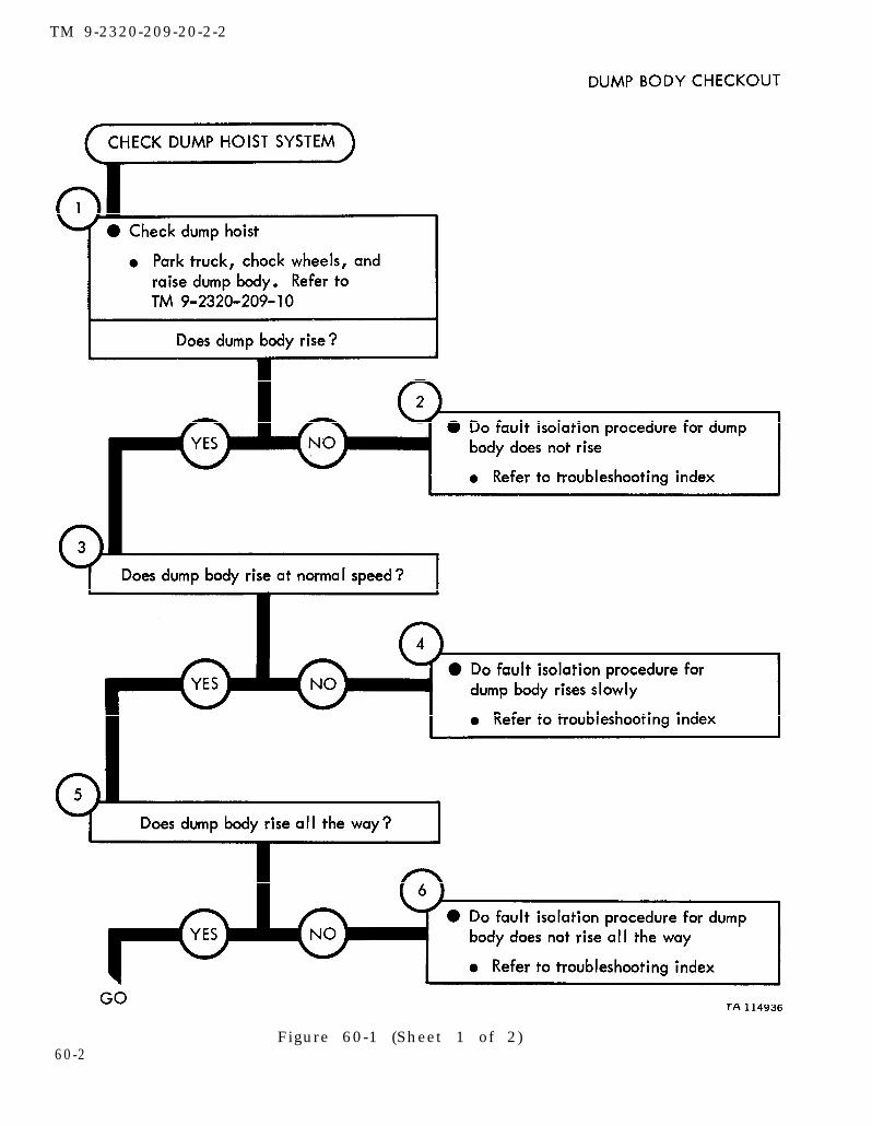
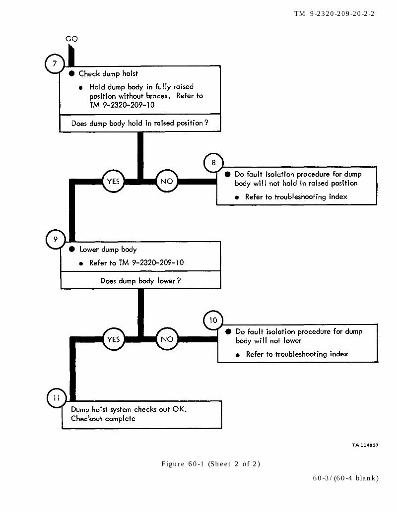
60-1
61-161-2
62-162-2
63-1
64-1
65-165-2
66-166-2
67-1
68-1
Page
55-155-1
56-156-1
57-157-1
58-158-1
59-1
60-1
61-161-1
62-162-1
63-1
64-1
65-165-1
66-166-1
67-1
68-1
iv

TM 9-2320-209-20-2-2
TABLE OF CONTENTS-CONT
CHAPTER 69.
CHAPTER 70.
CHAPTER 71.
CHAPTER 72.
CHAPTER 73.
CHAPTER 74.
CHAPTER 75.
CHAPTER 76.
CHAPTER 77.
CHAPTER 78.
CHAPTER 79.
CHAPTER 80.
CHAPTER 81.
Paragraph
FUEL TANK BODY (TRUCK M49A2C)TROUBLESHOOTINGEquipment Items Covered . . . . . . . . . . . . . . . . . . .Equipment Items Not Covered . . . . . . . . . . . . . . .
FUEL TANK BODY (TRUCK M49A2C)TROUBLESHOOTING SUMMARYGeneral . . . . . . . . . . . . . . . . . . . . . . . . . . . . . . . . . . .Procedures . . . . . . . . . . . . . . . . . . . . . . . . . . . . . . . . .
FUEL TANK BODY (TRUCK M49A2C)SUPPORT DIAGRAMSGeneral . . . . . . . . . . . . . . . . . . . . . . . . . . . . . . . . . . . .
FUEL TANK BODY (TRUCK M49A2C)CHECKOUT PROCEDURESGeneral . . . . . . . . . . . . . . . . . . . . . . . . . . . . . . . . . . . .
EARTH BORING MACHINETROUBLESHOOTINGEquipment Items Covered . . . . . . . . . . . . . . . . . . .Equipment Items Not Covered . . . . . . . . . . . . . . .
EARTH BORING MACHINE TROUBLESHOOTINGSUMMARY
General . . . . . . . . . . . . . . . . . . . . .Procedures . . . . . . . . . . . . . . . . . . . . . . . . . . . . . . . . .
EARTH BORING MACHINE SUPPORTDIAGRAMSGeneral . . . . . . . . . . . . . . . . . . . . . . . . . . . . . . . . . . . . .
EARTH BORING MACHINE CHECKOUTPROCEDURESGeneral . . . . . . . . . . . . . . . . . . . . . . . . . . . . . . . . . . .
FRONT WINCH TROUBLESHOOTINGEquipment Items Covered . . . . . . . . . . . . . .Equipment Items Not Covered . . . . . . . . . . . .
FRONT WINCH TROUBLEHSOOTINGSUMMARYGeneral . . . . . . . . . . . . . . . . . . . . . . . . . . . . . . . . .Procedures . . . . . . . . . . . . . . . . . . . . . . . . . . . . . . . . .
FRONT WINCH CHECKOUT PROCEDURESGeneral . . . . . . . . . . . . . . . . . . . . . . . . . . . . . . . . . . . .
EARTH BORING MACHINE REAR WINCHTROUBLESHOOTINGEquipment Items Covered . . . . . . . . . . . . . . . . . . .Equipment Items Not Covered . . . . . . . . . . . . . . .
PIPELINE CONSTRUCTION TRUCK REARWINCH TROUBLESHOOTINGEquipment Items Covered . . . . . . . . . . . . . . . . . . .Equipment Items Not Covered . . . . . . . . . . . . . . .
69-169-2
70-170-2
71-1
72-1
73-173-2
74-174-2
75-1
76-1
77-177-2
78-178-2
79-1
80-180-2
81-181-2
Page
69-169-1
70-170-1
71-1
72-1
73-173-1
74-174-1
75-1
76-1
77-177-1
78-178-1
79-1
80-180-1
81-181-1
v
TM 9-2320-209-20-2-2
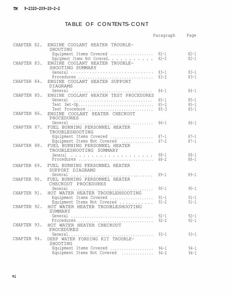
CHAPTER 82.
CHAPTER 83.
CHAPTER 84.
CHAPTER 85.
CHAPTER 86.
CHAPTER 87.
CHAPTER 88.
CHAPTER 89.
CHAPTER 90.
CHAPTER 91.
CHAPTER 92.
CHAPTER 93.
CHAPTER 94.
TABLE OF CONTENTS-CONT
Paragraph
ENGINE COOLANT HEATER TROUBLE-SHOOTINGEquipment Items Covered . . . . . . . . . . . . . . . . . . .Equipment Items Not Covered. . . . . . . . . . .
ENGINE COOLANT HEATER TROUBLE-SHOOTING SUMMARYGeneral . . . . . . . . . . . . . . . . . . . . . . . . . . . . . . .Procedures . . . . . . . . . . . . . . . . . . . . . . . . . . . . . . .
ENGINE COOLANT HEATER SUPPORTDIAGRAMSGeneral . . . . . . . . . . . . . . . . . . . . . . . . . . . . . . . . . . .
ENGINE COOLANT HEATER TEST PROCEDURESGeneral . . . . . . . . . . . . . . . . . . . . . . . . . . . . . . . . . .Test Set-Up. . . . . . . . . . . . . . . . . . . . . . . . . . . . . . . . .Test Procedure . . . . . . . . . . . . . . . . . . . . . . . . . . . . .
ENGINE COOLANT HEATER CHECKOUTPROCEDURESGeneral . . . . . . . . . . . . . . . . . . . . . . . . . . . . . . . . . . . .
FUEL BURNING PERSONNEL HEATERTROUBLESHOOTINGEquipment Items Covered . . . . . . . . . . . . . . . . . . .Equipment Items Not Covered . . . . . . . . . . . . . .
FUEL BURNING PERSONNEL HEATERTROUBLESHOOTING SUMMARYGeneral . . . . . . . . . . . . . . . . . . . .Procedures . . . . . . . . . . . . . . . . . . . . . . . . . . . . . . . . .
FUEL BURNING PERSONNEL HEATERSUPPORT DIAGRAMSGeneral . . . . . . . . . . . . . . . . . . . . . . ... . . . . .
FUEL BURNING PERSONNEL HEATERCHECKOUT PROCEDURESGeneral . . . . . . . . . . . . . . . . . . . . . . . . . . . . . . . . . . . .
HOT WATER HEATER TROUBLEHSOOTINGEquipment Items Covered . . . . . . . . . . . . . . . . . . .Equipment Items Not Covered . . . . . . . . . . .
HOT WATER HEATER TROUBLESHOOTINGSUMMARYGeneral . . . . . . . . . . . . . . . . . . . . . . . . . . . . . . . . . . . .Procedures . . . . . . . . . . . . . . . . . . . . . . . . . . . . . . . . .
HOT WATER HEATER CHECKOUTPROCEDURESGeneral . . . . . . . . . . . . . . . . . . . . . . . . . . . . . . . . . . . . .
DEEP WATER FORDING KIT TROUBLE-SHOOTINGEquipment Items Covered . . . . . . . . . . . . . . . . . . .Equipment Items Not Covered . . . . . . . . . . . . . .
82-182-2
83-183-2
84-1
85-185-285-3
86-1
87-187-2
88-188-2
89-1
90-1
91-191-2
92-192-2
93-1
94-194-2
Page
82-182-1
83-183-1
84-1
85-185-185-1
86-1
87-187-1
88-188-1
89-1
90-1
91-191-1
92-192-1
93-1
94-194-1
vi
TM 9-2320-209-20-2-2
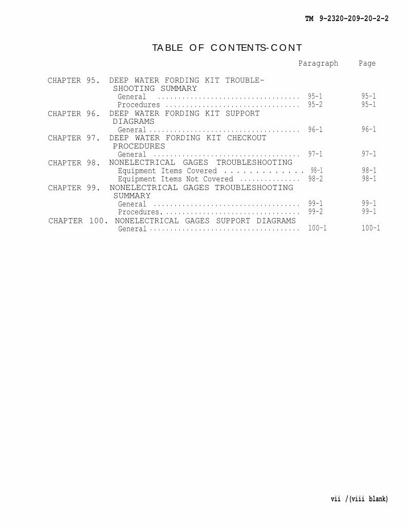
CHAPTER 95.
CHAPTER 96.
CHAPTER 97.
CHAPTER 98.
CHAPTER 99.
TABLE OF CONTENTS-CONTParagraph
DEEP WATER FORDING KIT TROUBLE-SHOOTING SUMMARYGeneral . . . . . . . . . . . . . . . . . . . . . . . . . . . . . . . . . . . 95-1Procedures . . . . . . . . . . . . . . . . . . . . . . . . . . . . . . . . . 95-2
DEEP WATER FORDING KIT SUPPORTDIAGRAMSGeneral . . . . . . . . . . . . . . . . . . . . . . . . . . . . . . . . . . . . . 96-1
DEEP WATER FORDING KIT CHECKOUTPROCEDURESGeneral . . . . . . . . . . . . . . . . . . . . . . . . . . . . . . . . . . . . 97-1
NONELECTRICAL GAGES TROUBLESHOOTINGEquipment Items Covered . . . . . . . . . . . . . 98-1Equipment Items Not Covered . . . . . . . . . . . . . . . 98-2
NONELECTRICAL GAGES TROUBLESHOOTINGSUMMARYGeneral . . . . . . . . . . . . . . . . . . . . . . . . . . . . . . . . . . . . 99-1Procedures. . . . . . . . . . . . . . . . . . . . . . . . . . . . . . . . . . 99-2
CHAPTER 100. NONELECTRICAL GAGES SUPPORT DIAGRAMSGeneral . . . . . . . . . . . . . . . . . . . . . . . . . . . . . . . . . . . . . 100-1
Page
95-195-1
96-1
97-1
98-198-1
99-199-1
100-1
vii /(viii blank)

TM 9-2320-209-20-2-2
CHAPTER 26
ELECTRICAL SYSTEM TROUBLESHOOTING SUMMARY
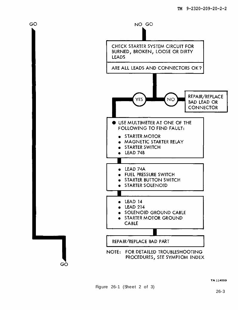
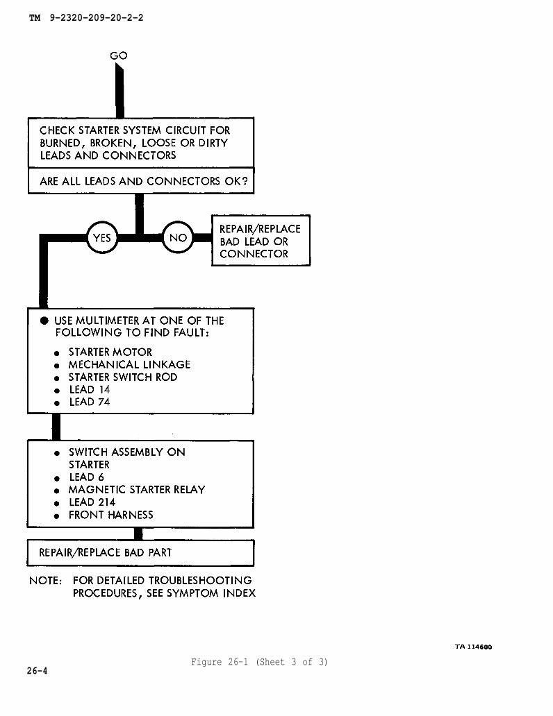
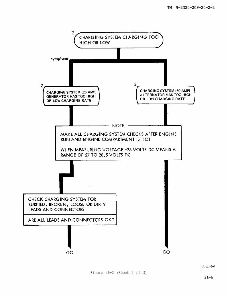
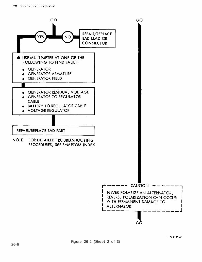
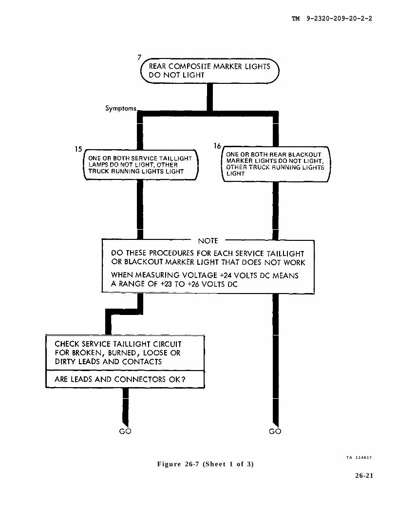
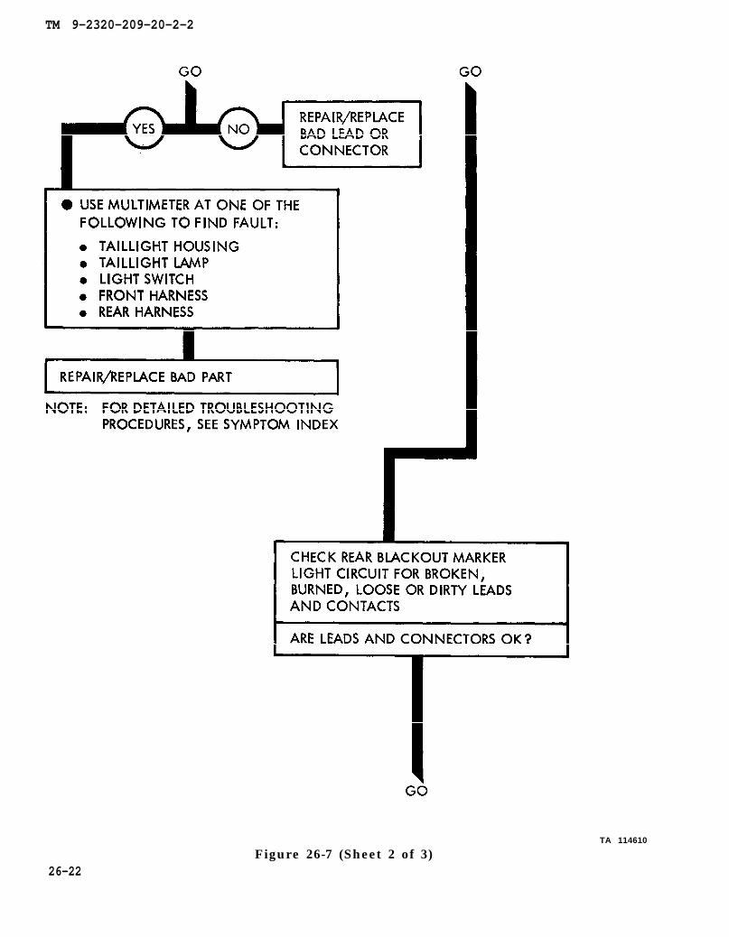
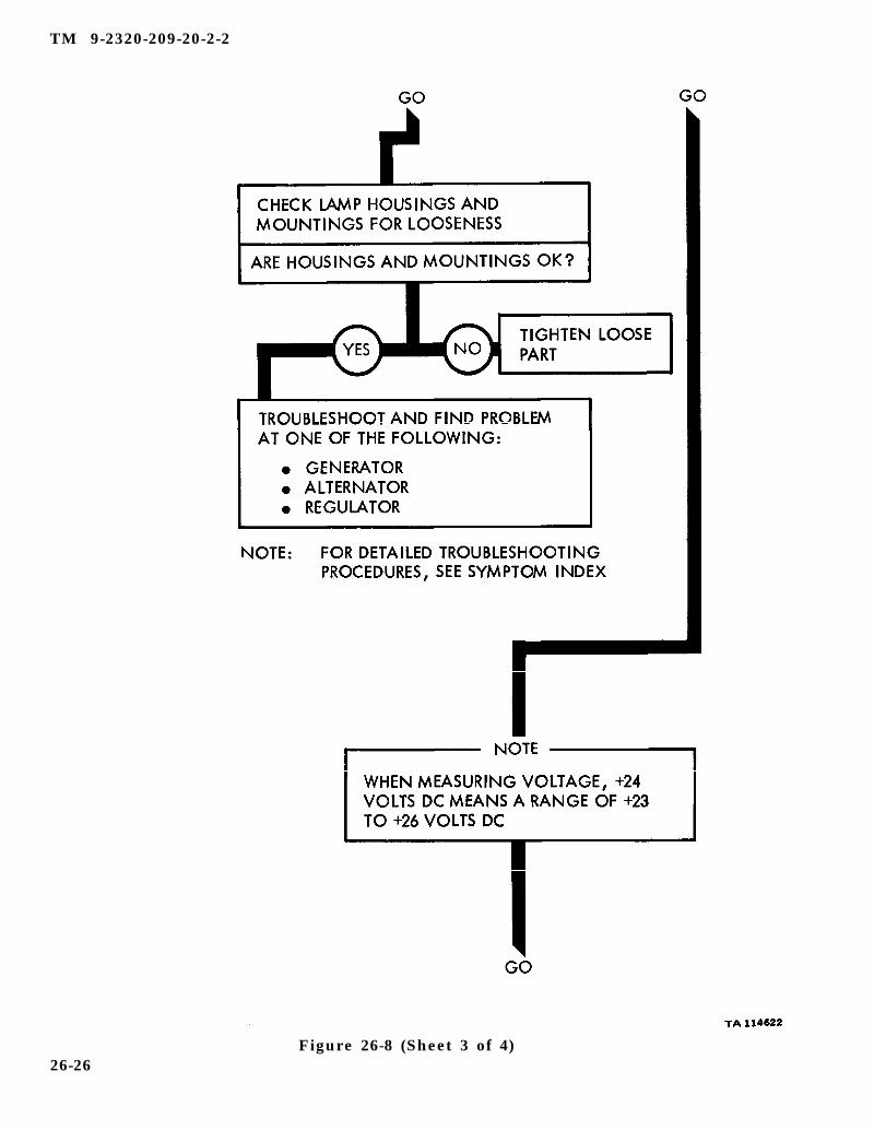
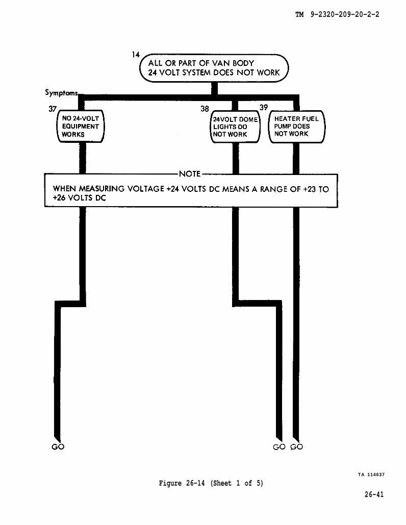
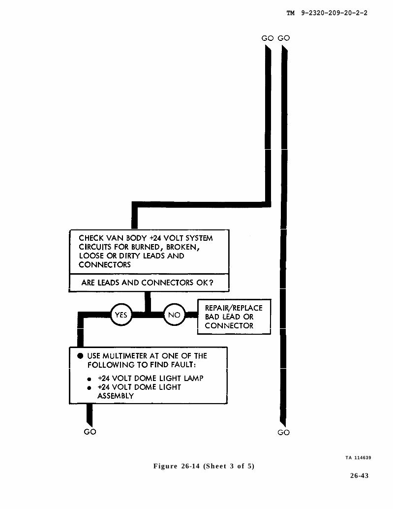
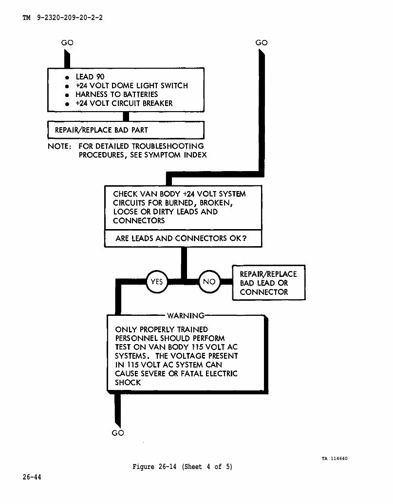
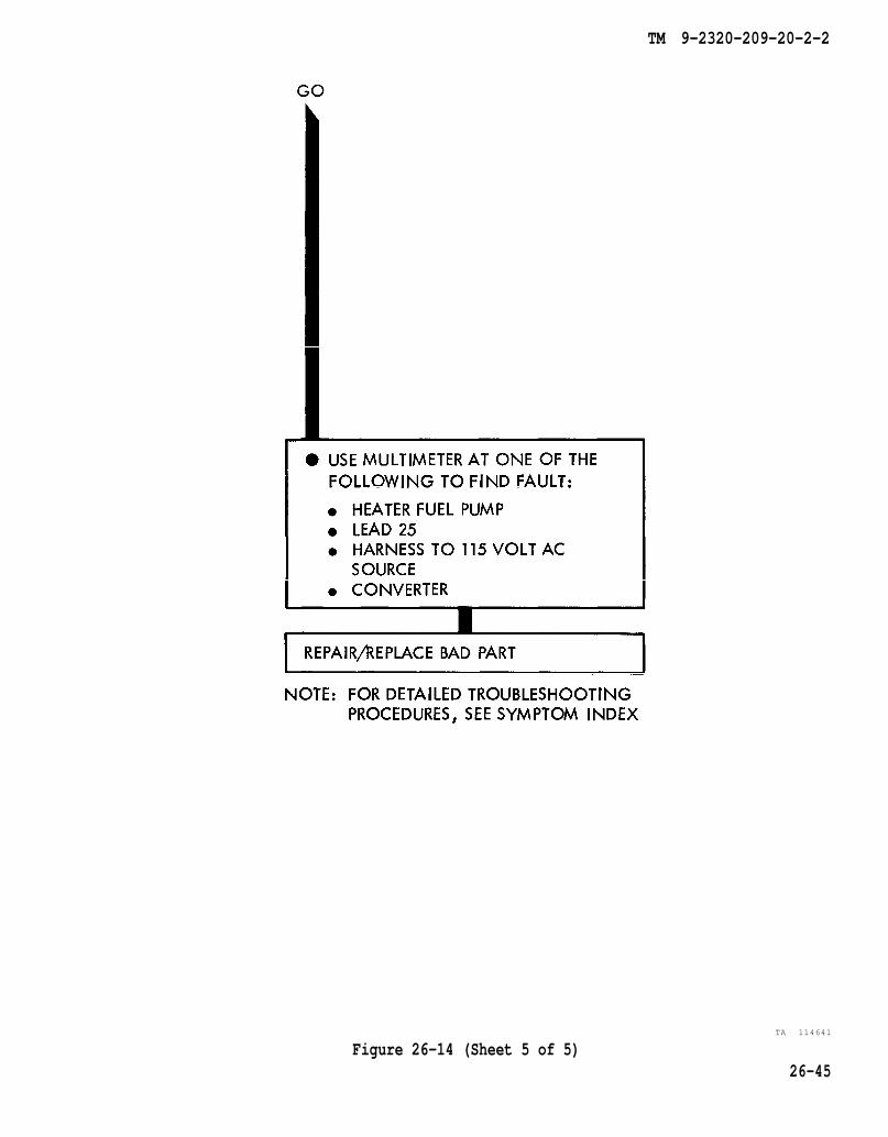
26-1. GENERAL. This chapter gives a summary of troubleshooting procedures givenin chapter 25 for the electrical system.
26-2. PROCEDURES. The summary in this chapter covers all fault symptoms foundin the detailed troubleshooting procedures. Chapter 7 outlines a sample troubleshoot-ing procedure. The summary procedures are based on the "what-to-do" portions ofthe detailed procedures and do not include the “how-to-do-it” instructions. Warn-ings, cautions, and notes are given where needed.
26-1

TM 9-2320-209-20-2-2
Figure 26-1 (Sheet 1 of 3)26-2
TM 9-2320-209-20-2-2
Figure 26-1 (Sheet 2 of 3)26-3
TM 9-2320-209-20-2-2
26-4Figure 26-1 (Sheet 3 of 3)
TM 9-2320-209-20-2-2
Figure 26-2 (Sheet 1 of 3)26-5
TM 9-2320-209-20-2-2
26-6Figure 26-2 (Sheet 2 of 3)
TM 9-2320-209-20-2-2
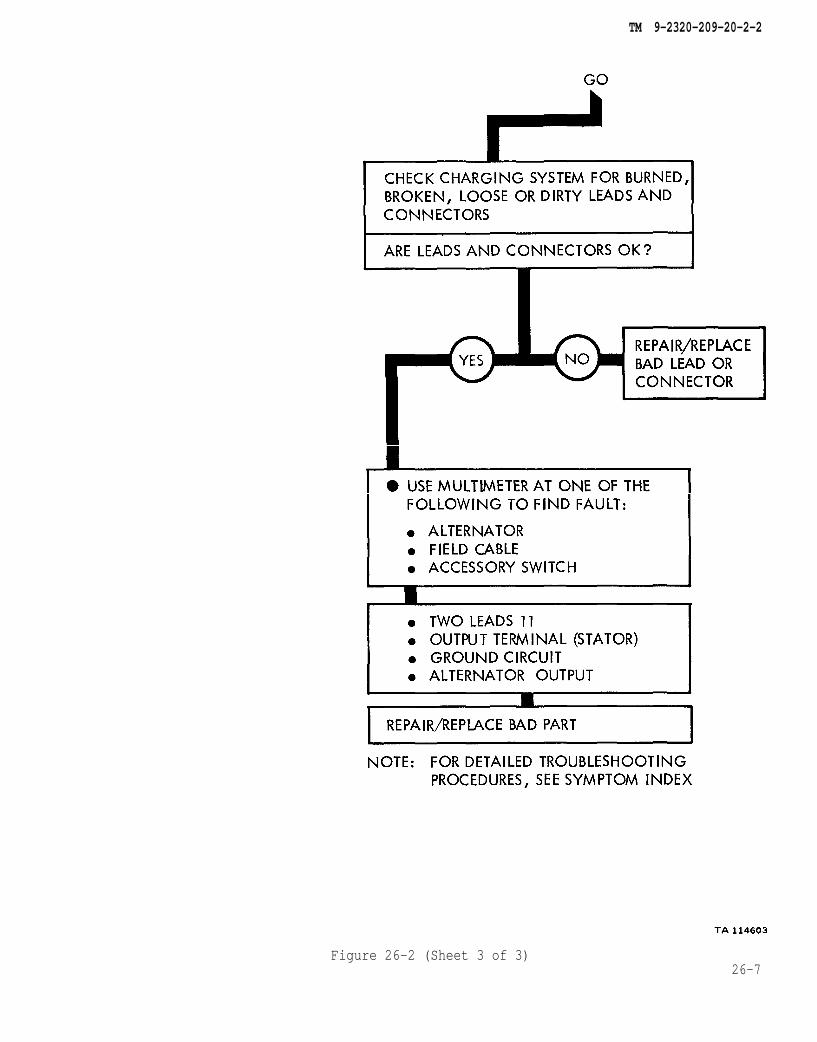
Figure 26-2 (Sheet 3 of 3)26-7
TM 9-2320-209-20-2-2
Figure 26-3 (Sheet 1 of 4)26-8
TM 9-2320-209-20-2-2
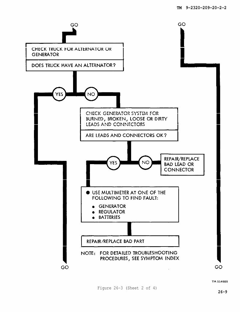
Figure 26-3 (Sheet 2 of 4)26-9
TM 9-2320-209-20-2-2
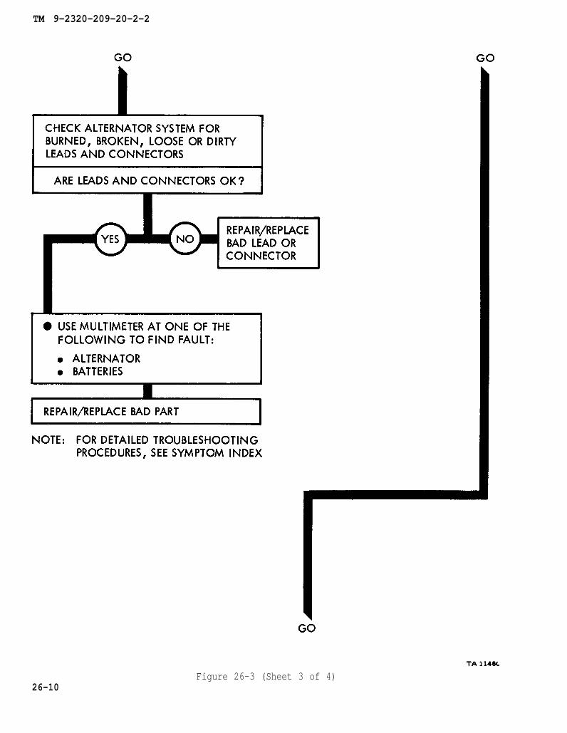
Figure 26-3 (Sheet 3 of 4)26-10
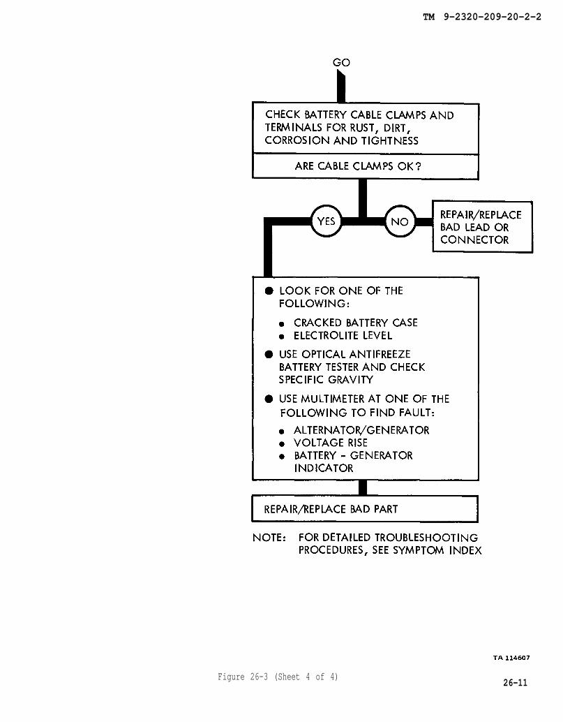
TM 9-2320-209-20-2-2
Figure 26-3 (Sheet 4 of 4)26-11

TM 9-2320-209-20-2-2
26-12Figure 26-4 (Sheet 1 of 3)
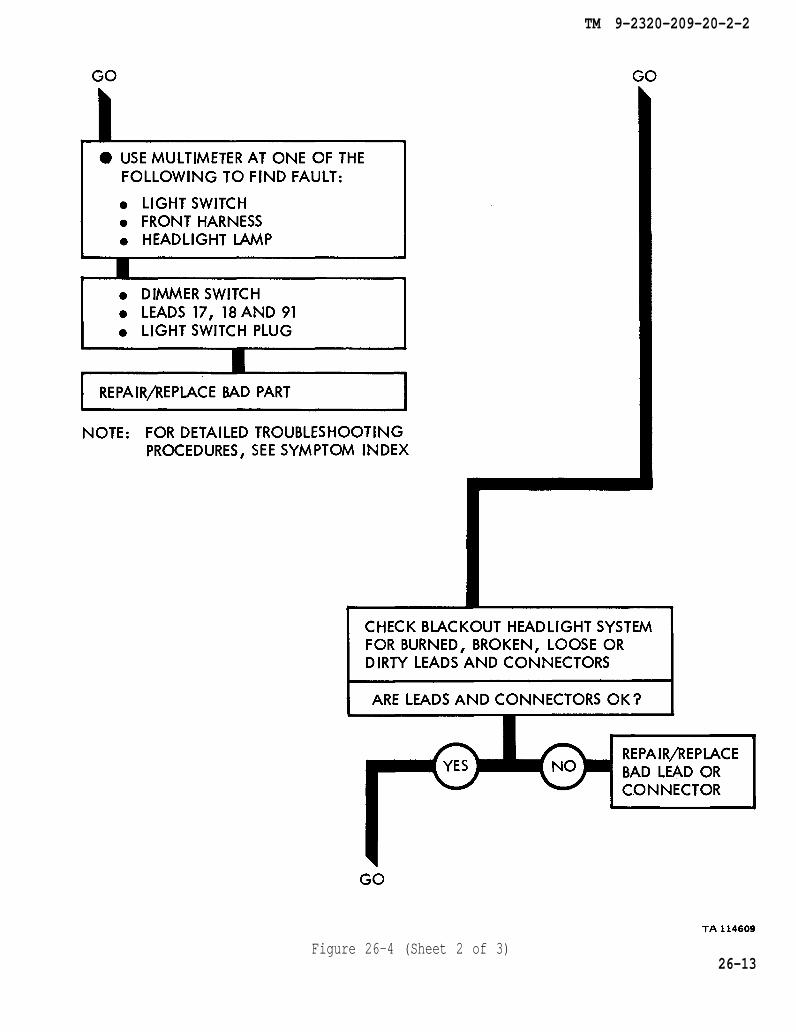
TM 9-2320-209-20-2-2
Figure 26-4 (Sheet 2 of 3)26-13
TM 9-2320-209-20-2-2
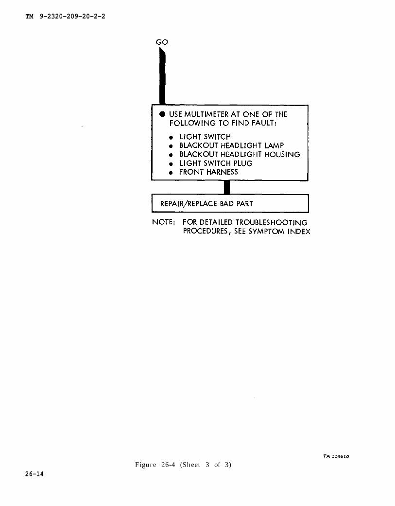
Figure 26-4 (Sheet 3 of 3)26-14
TM 9-2320-209-20-2-2
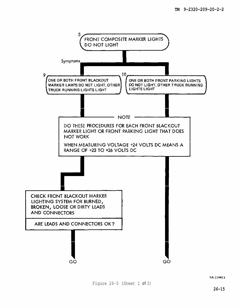
Figure 26-5 (Sheet 1 of 3)26-15
TM 9-2320-209-20-2-2
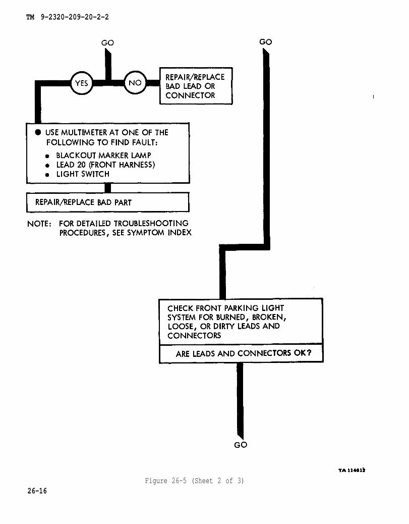
Figure 26-5 (Sheet 2 of 3)26-16
TM 9-2320-209-20-2-2
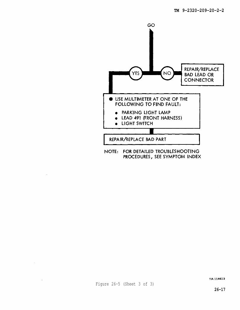
Figure 26-5 (Sheet 3 of 3)26-17
TM 9-2320-209-20-2-2
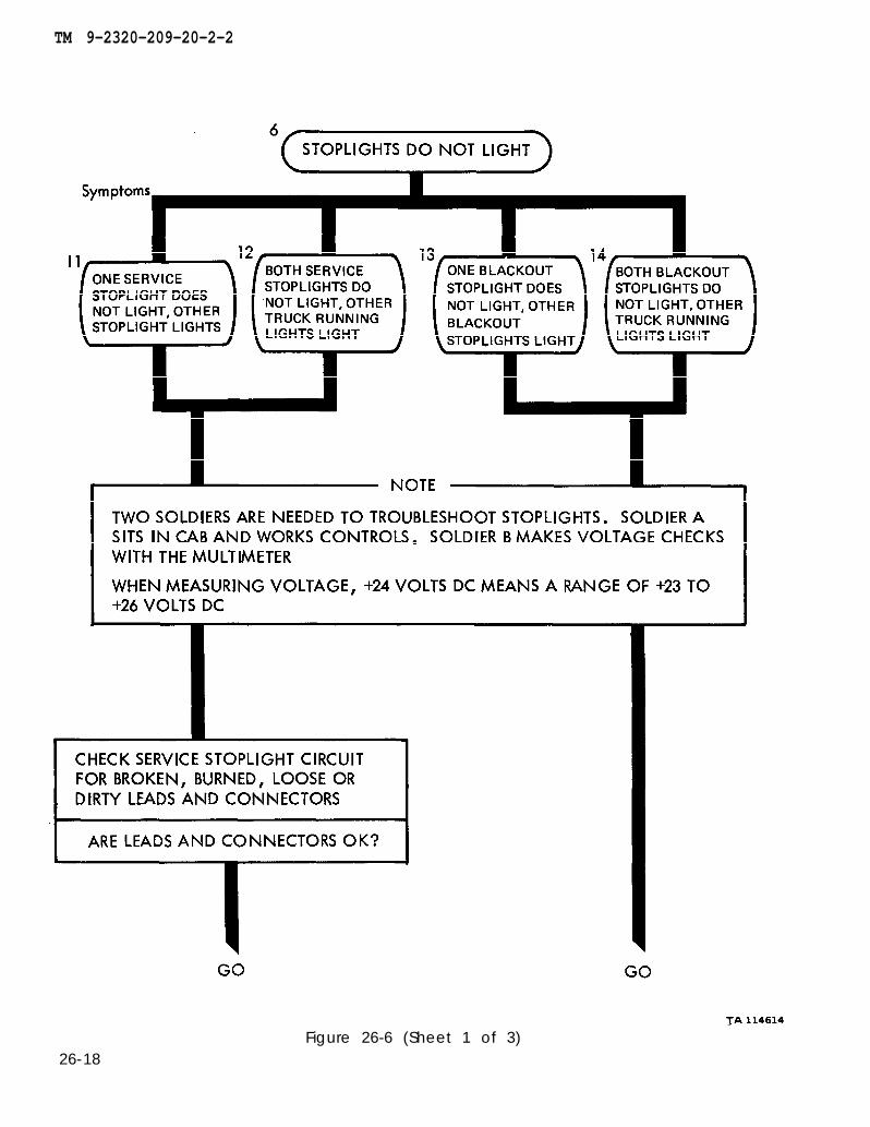
26-18Figure 26-6 (Sheet 1 of 3)

TM 9-2320-209-20-2-2
Figure 26-6 (Sheet 2 of 3)26-19
TM 9-2320-209-20-2-2
TA 114616
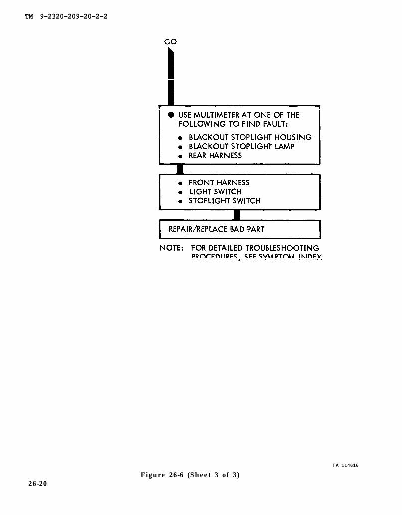
26-20Figure 26-6 (Sheet 3 of 3)
TM 9-2320-209-20-2-2
Figure 26-7 (Sheet 1 of 3)TA 114617
26-21
TM 9-2320-209-20-2-2
Figure 26-7 (Sheet 2 of 3)TA 114610
26-22

TM 9-2320-209-20-2-2
Figure 26-7 (Sheet 3 of 3)TA 114619
26-23

TM 9-2320-209-20-2-2
TA 114620
Figure 26-8 (Sheet 1 of 4)26-24
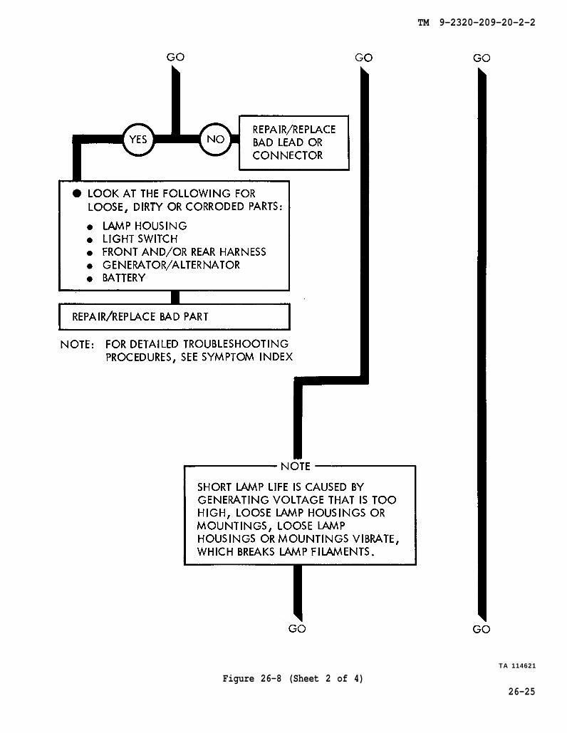
Figure 26-8 (Sheet 2 of 4)
TM 9-2320-209-20-2-2
TA 114621
26-25
TM 9-2320-209-20-2-2
26-26Figure 26-8 (Sheet 3 of 4)
TM 9-2320-209-20-2-2
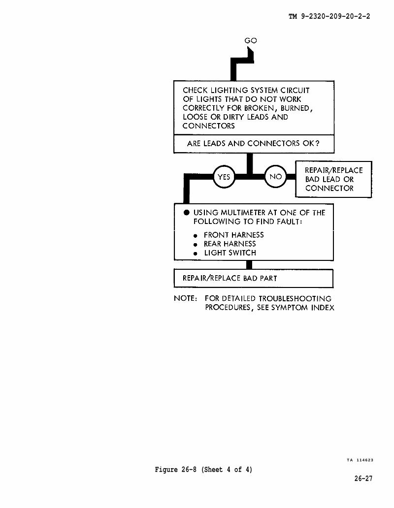
Figure 26-8 (Sheet 4 of 4)T A 1 1 4 6 2 3
26-27

TM 9-2320-209-20-2-2
Figure 26-9 (Sheet 1 of 3)TA 114624
26-28
TM 9-2320-209-20-2-2
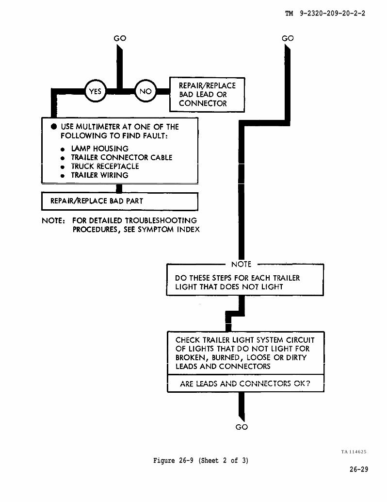
Figure 26-9 (Sheet 2 of 3)TA 114625
26-29

TM 9-2320-209-20-2-2
TA 114626
Figure 26-9 (Sheet 3 of 3)26-30

TM 9-2320-209-20-2-2
Figure 26-10 (Sheet 1 of 2)TA 114627
26-31
TM 9-2320-209-20-2-2
TA 114628
Figure 26-10 (Sheet 2 of 2)26-32

TM 9-2320-209-20-2-2
Figure 26-11 (Sheet 1 of 2)T A 1 1 4 6 2 9
26-33
TM 9-2320-209-20-2-2
TA 114630
26-34Figure 26-11 (Sheet 2 of 2)
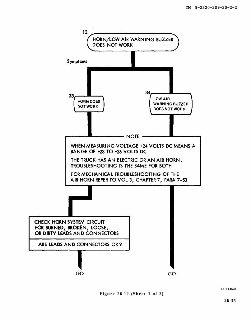
CHAPTER 7, PARA 7-53
TM 9-2320-209-20-2-2
Figure 26-12 (Sheet 1 of 3)TA 114631
26-35
TM 9-2320-209-20-2-2
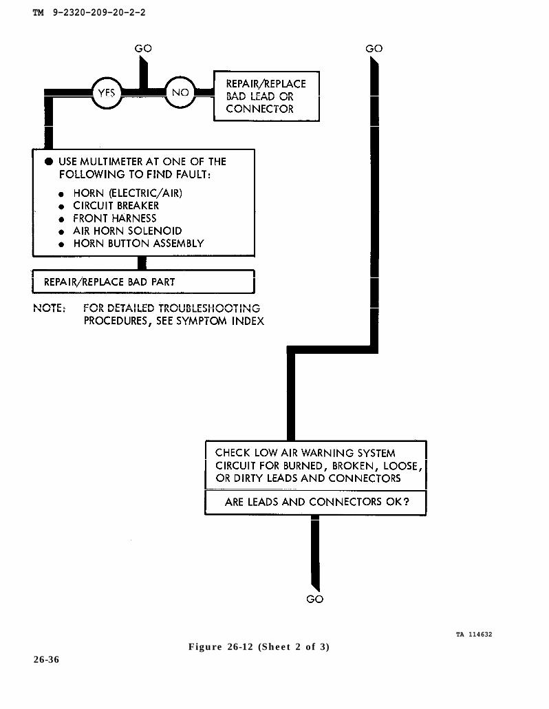
Figure 26-12 (Sheet 2 of 3)TA 114632
26-36
TM 9-2320-209-20-2-2
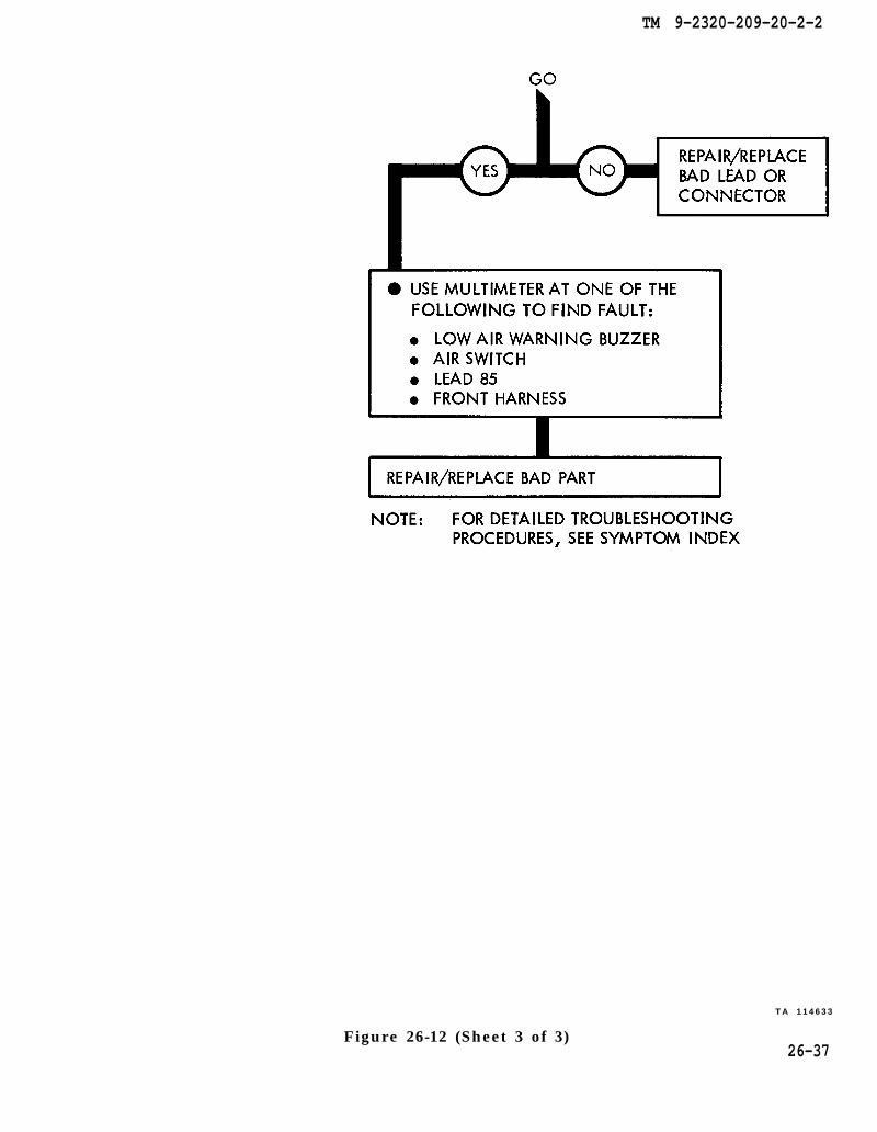
Figure 26-12 (Sheet 3 of 3)
TA 114633
26-37
TM 9-2320-209-20-2-2
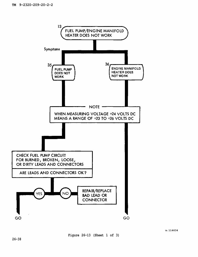
Figure 26-13 (Sheet 1 of 3)
TA 114634
26-38

TM 9-2320-209-20-2-2
Figure 26-13 (Sheet 2 of 3)TA 114635
26-39

TM 9-2320-209-20-2-2
Figure 26-13 (Sheet 3 of 3)TA 114636
26-40
TM 9-2320-209-20-2-2
Figure 26-14 (Sheet 1 of 5)TA 114637
26-41

TM 9-2320-209-20-2-2
Figure 26-14 (Sheet 2 of 5)TA 114638
26-42
TM 9-2320-209-20-2-2
TA 114639
Figure 26-14 (Sheet 3 of 5)26-43
TM 9-2320-209-20-2-2
Figure 26-14 (Sheet 4 of 5)TA 114640
26-44
TM 9-2320-209-20-2-2
Figure 26-14 (Sheet 5 of 5)TA 114641
26-45

TM 9-2320-209-20-2-2
TA 114642
26-46Figure 26-15 (Sheet 1 of 6)
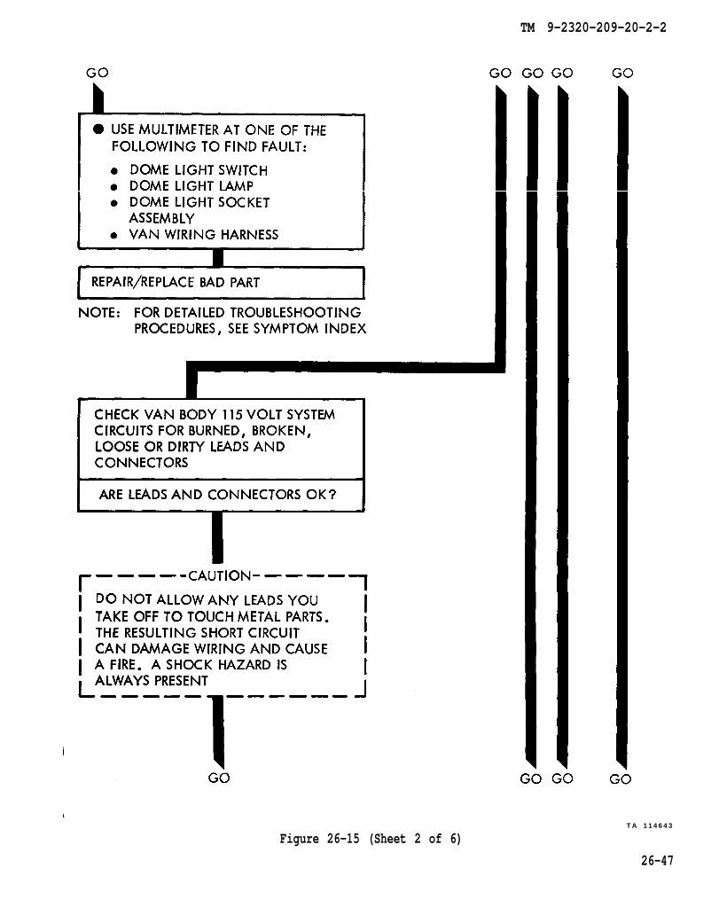
TM 9-2320-209-20-2-2
Figure 26-15 (Sheet 2 of 6)TA 114643
26-47
TM 9-2320-209-20-2-2
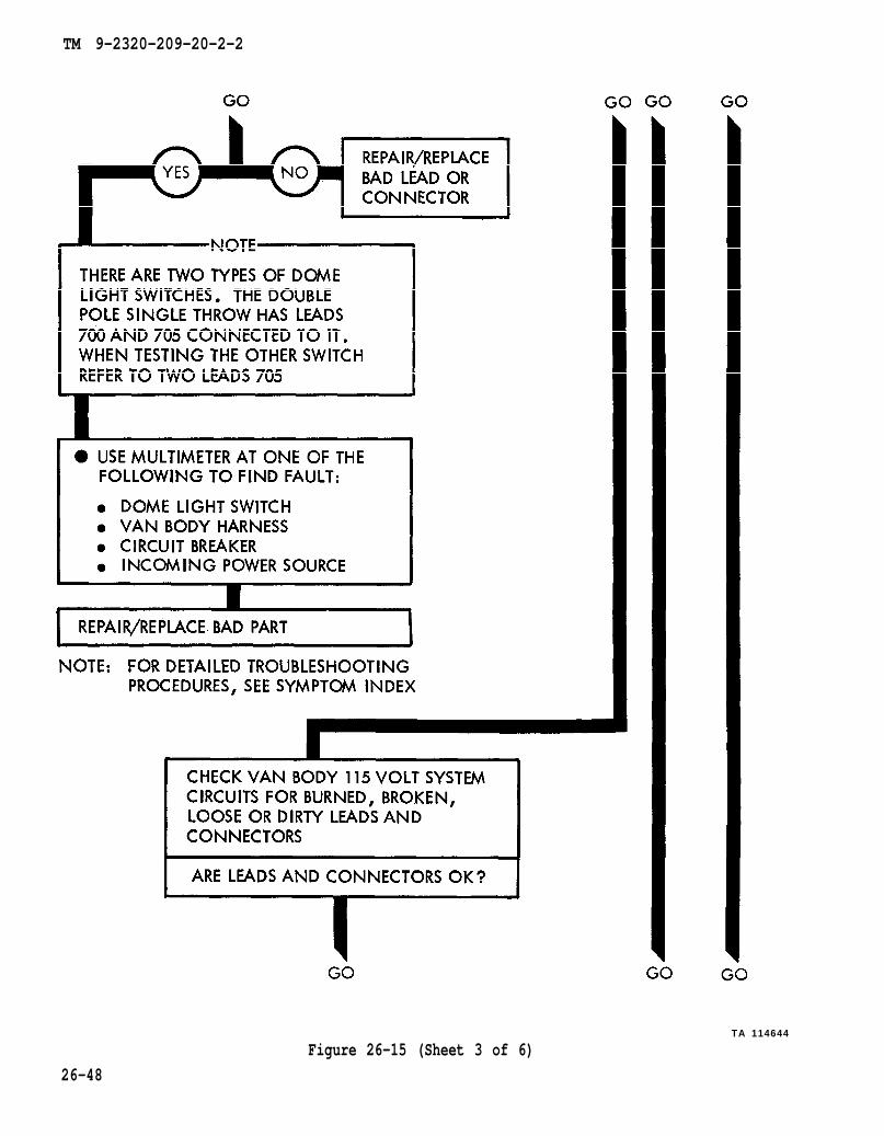
TA 114644
Figure 26-15 (Sheet 3 of 6)
26-48

TM 9-2320-209-20-2-2
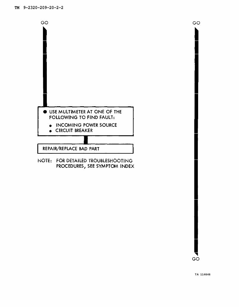
TA 114645
Figure 26-15 (Sheet 4 of 6)26-49
TM 9-2320-209-20-2-2
TA 114646
TM 9-2320-209-20-2-2
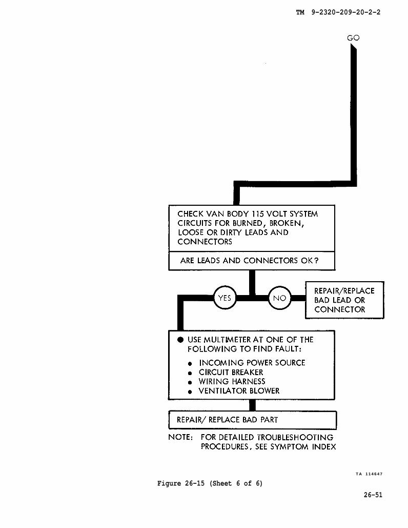
TA 114647
Figure 26-15 (Sheet 6 of 6)
26-51

TM 9-2320-209-20-2-2
TA 114648
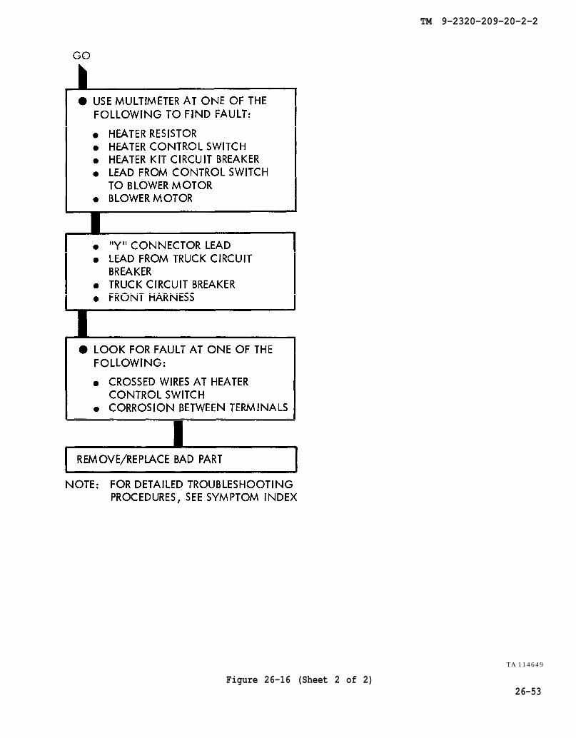
26-52Figure 26-16 (Sheet 1 of 2)
TM 9-2320-209-20-2-2
Figure 26-16 (Sheet 2 of 2)
TA 114649
26-53
TM 9-2320-209-20-2-2
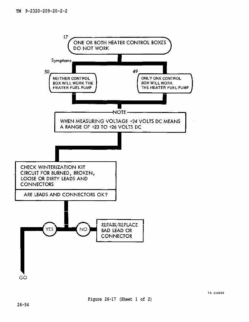
Figure 26-17 (Sheet 1 of 2)TA 114650
26-54

TM 9-2320-209-20-2-2
TA 114651
Figure 26-17 (Sheet 2 of 2)26-55/ (26-56 blank)


TM 9-2320-209-20-2-2
CHAPTER 27
ELECTRICAL SYSTEM SUPPORT DIAGRAMS
27-1. GENERAL. This chapter gives the diagrams you need when doing trouble-shooting procedures in chapter 25. Table 3-1 is a complete listing of all supportdiagrams used in this manual.
27-1

Figure 27-1.
TM 9-2320-209-20-2-2
27-2

Figure 27-2.
TM 9-2320-209-20-2-2
27-3

Figure 27-3.
TM 9-2320-209-20-2-2
2 7 - 4
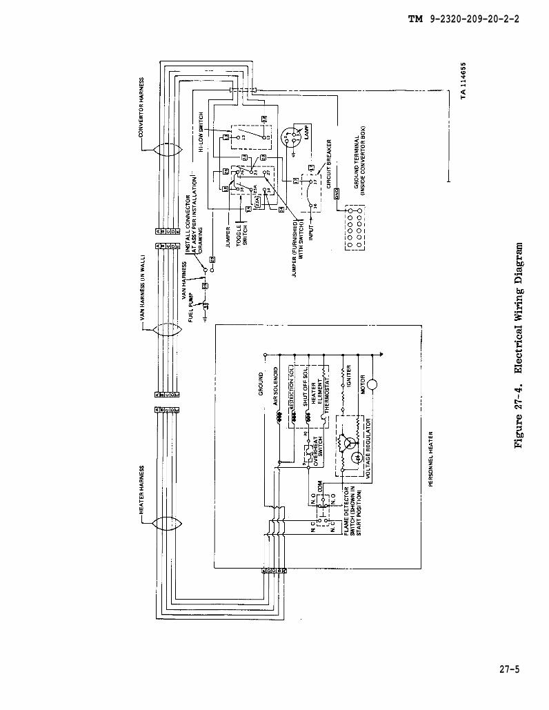
Figure 27-4.
TM 9-2320-209-20-2-2
27-5
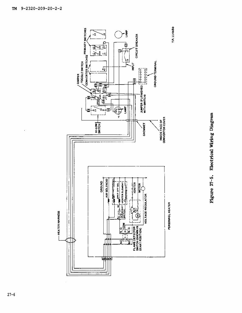
Figure 27-5.
TM 9-2320-209-20-2-2
27-6
TM 9-2320-209-20-2-2
CHAPTER 28
MULTIMETER TEST PROCEDURES
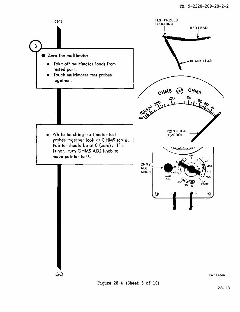
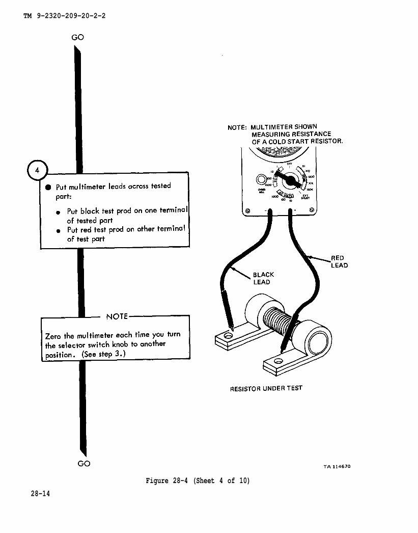
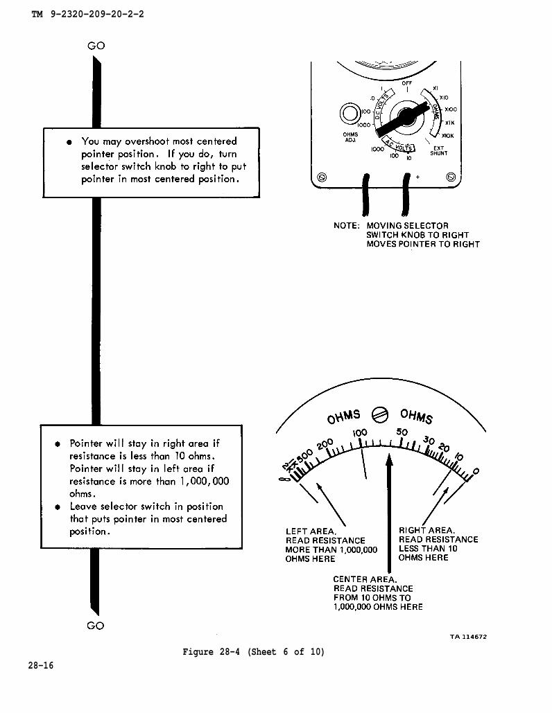
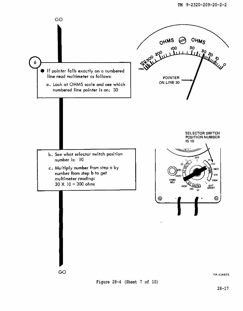
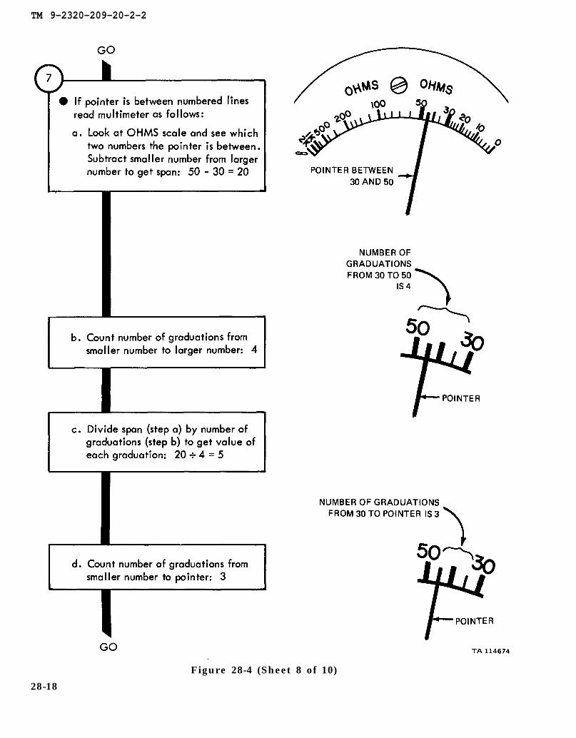
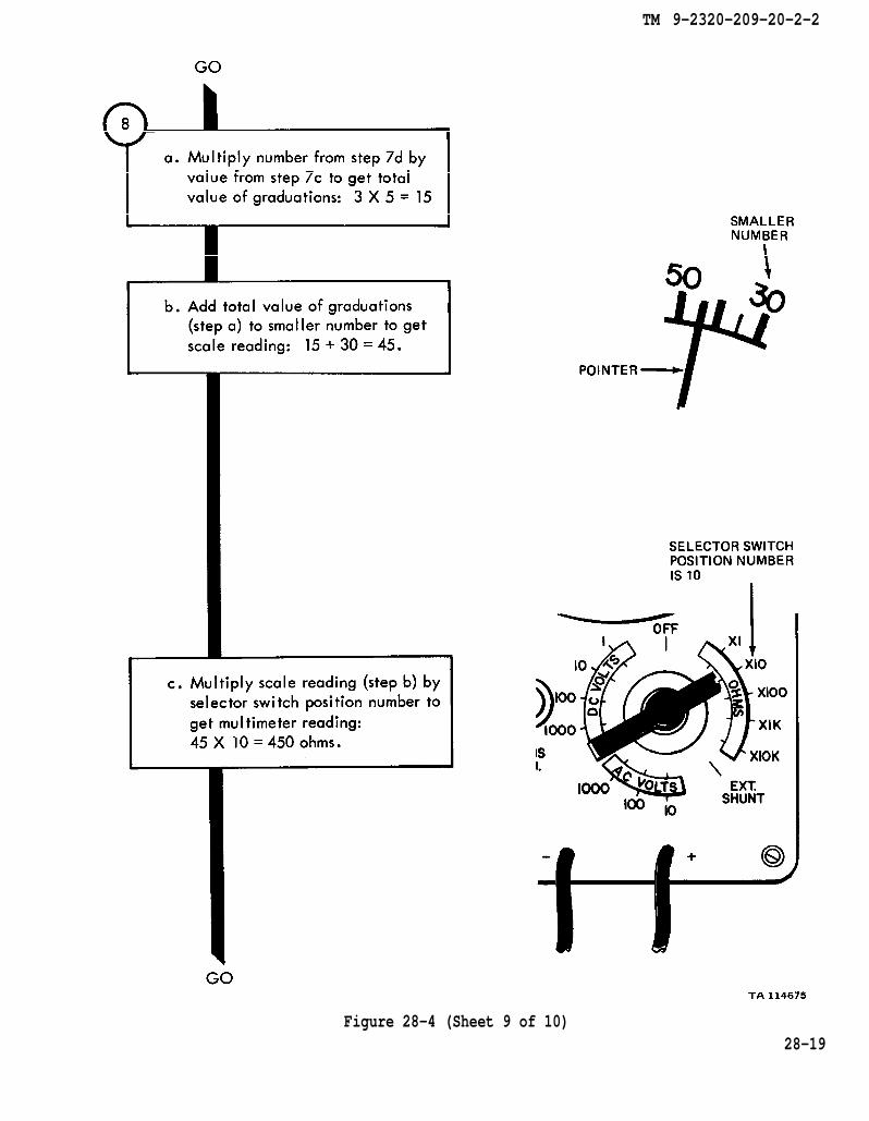
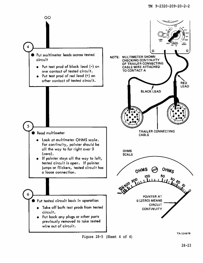
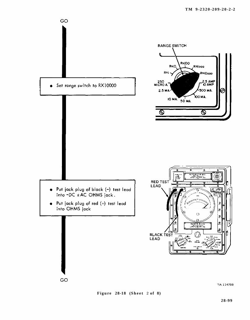
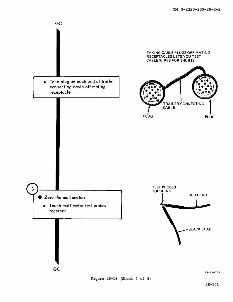
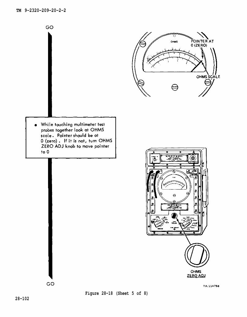
28-1. GENERAL. This chapter gives test procedures for the multimeter trouble-shooting.
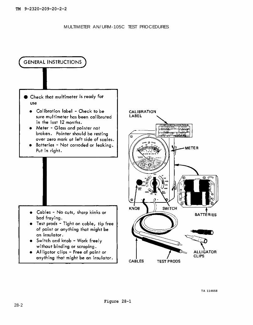
28-2. TEST SET-UP. Instructions for setup of test equipment and parts to betested are given before the test procedures. Illustrations are used, when needed,to show you how to hook up the test equipment to the part to be tested.
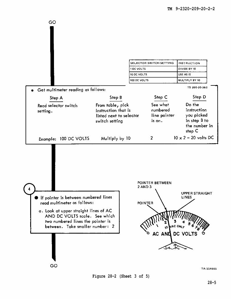
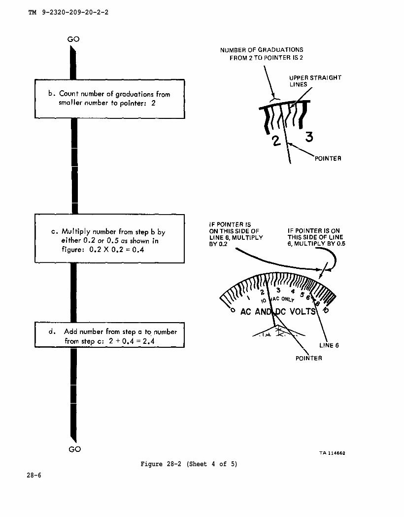
28-3. TEST PROCEDURE. Detailed step-by-step instructions, in flow chart form,are given for each test. The procedure calls out the type of test and the conditionof the truck system for each part of testing. The step-by-step test will lead you tothe bad component or to a fault symptom within a related system. Reference is madeto the fault symptom index, chapter 6, if the test shows a fault in another system.
28-1
TM 9-2320-209-20-2-2
MULTIMETER AN/URM-105C TEST PROCEDURES
TA 114658
28-2Figure 28-1

TM 9-2320-209-20-2-2
Figure 28-2 (Sheet 1 of 5)28-3

TM 9-2320-209-20-2-2
28-4Figure 28-2 (Sheet 2 of 5)
TM 9-2320-209-20-2-2
Figure 28-2 (Sheet 3 of 5)28-5
TM 9-2320-209-20-2-2
Figure 28-2 (Sheet 4 of 5)
28-6
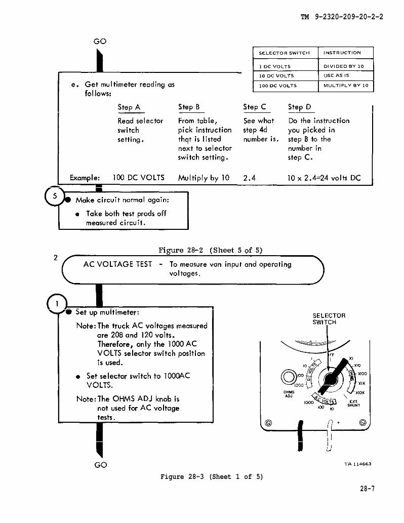
Figure 28-2
TM 9-2320-209-20-2-2
Figure 28-3 (Sheet 1 of 5)
28-7

TM 9-2320-209-20-2-2
28-8
Figure 28-3 (Sheet 2 of 5)

TM 9-2320-209-20-2-2
Figure 28-3 (Sheet 3 of 5)
28-9
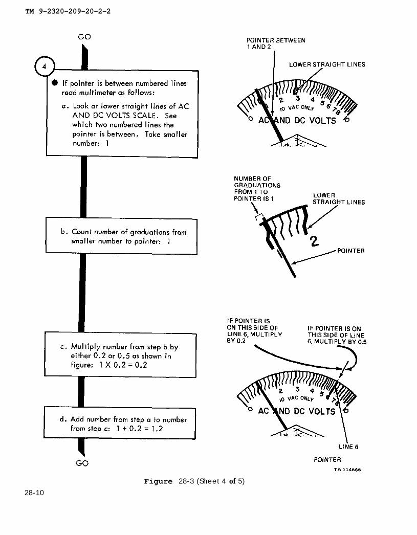
TM 9-2320-209-20-2-2
28-10Figure 28-3 (Sheet 4 of 5)
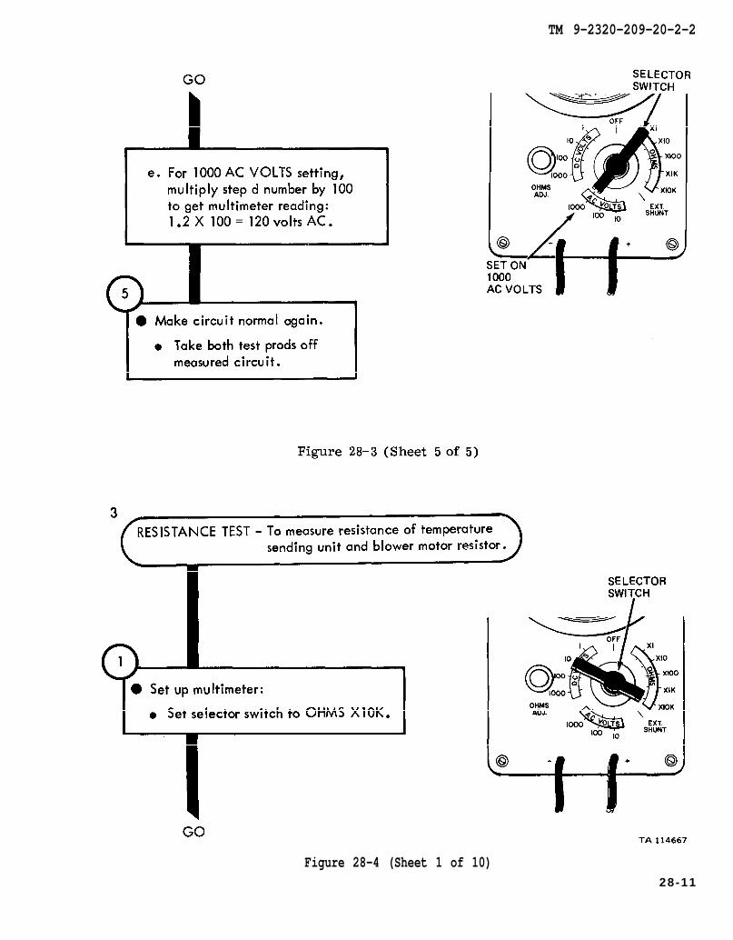
Figure 28-3
TM 9-2320-209-20-2-2
Figure 28-4 (Sheet 1 of 10)28-11
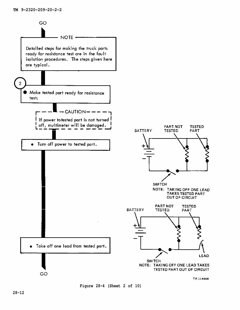
TM 9-2320-209-20-2-2
Figure 28-4 (Sheet 2 of 10)
28-12
TM 9-2320-209-20-2-2
Figure 28-4 (Sheet 3 of 10)28-13
TM 9-2320-209-20-2-2
Figure 28-4 (Sheet 4 of 10)
28-14

TM 9-2320-209-20-2-2
Figure 28-4 (Sheet 5 of 10)
28-15
TM 9-2320-209-20-2-2
Figure 28-4 (Sheet 6 of 10)28-16
TM 9-2320-209-20-2-2
Figure 28-4 (Sheet 7 of 10)28-17
TM 9-2320-209-20-2-2
28-18
Figure 28-4 (Sheet 8 of 10)
TM 9-2320-209-20-2-2
Figure 28-4 (Sheet 9 of 10)28-19
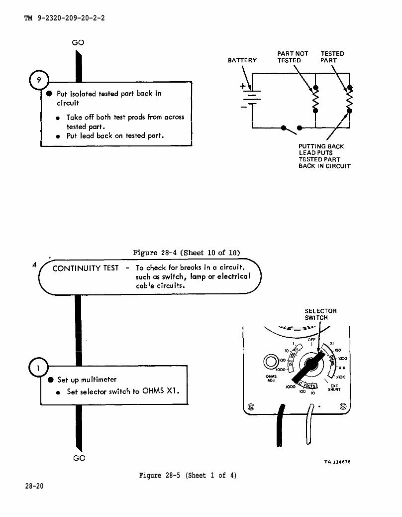
Figure 28-4
TM 9-2320-209-20-2-2
Figure 28-5 (Sheet 1 of 4)28-20

TM 9-2320-209-20-2-2
Figure 28-5 (Sheet 2 of 4)
28-21

TM 9-2320-209-20-2-2
28-22
Figure 28-5 (Sheet 3 of 4)
TM 9-2320-209-20-2-2
Figure 28-5 (Sheet 4 of 4)
28-23

TM 9-2320-209-20-2-2
Figure 28-6 (Sheet 1 of 5)
28-24

TM 9-2320-209-20-2-2
Figure 28-6 (Sheet 2 of 5)
28-25
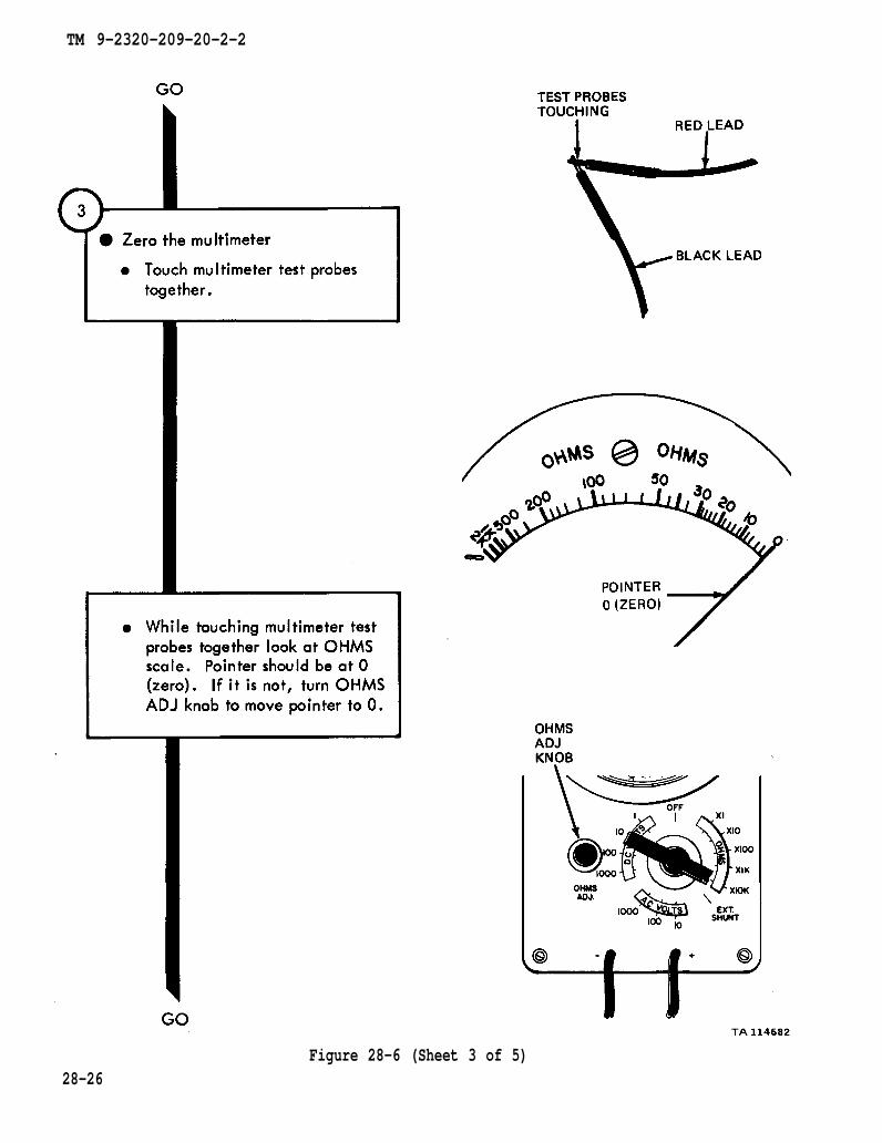
TM 9-2320-209-20-2-2
28-26Figure 28-6 (Sheet 3 of 5)

TM 9-2320-209-20-2-2
Figure 28-6 (Sheet 4 of 5)
28-27
TM 9-2320-209-20-2-2
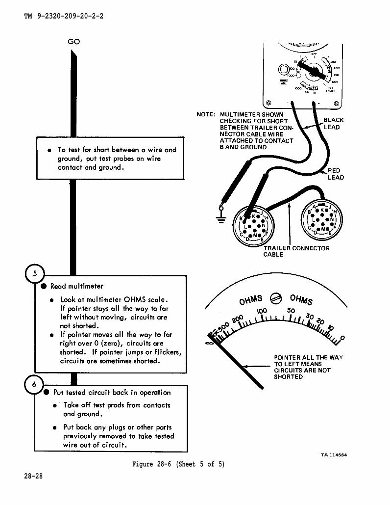
Figure 28-6 (Sheet 5 of 5)
28-28
TM 9-2320-209-20-2-2
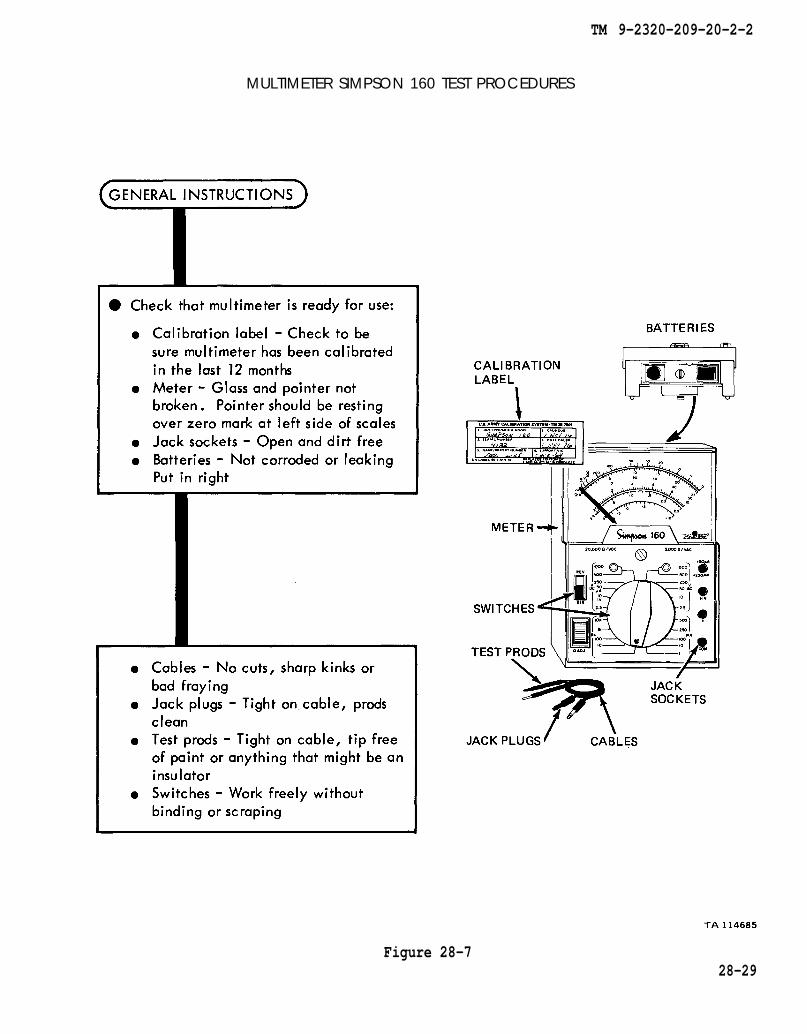
MULTIMETER SIMPSON 160 TEST PROCEDURES
Figure 28-728-29
TM 9-2320-209-20-2-2
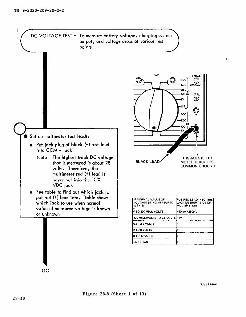
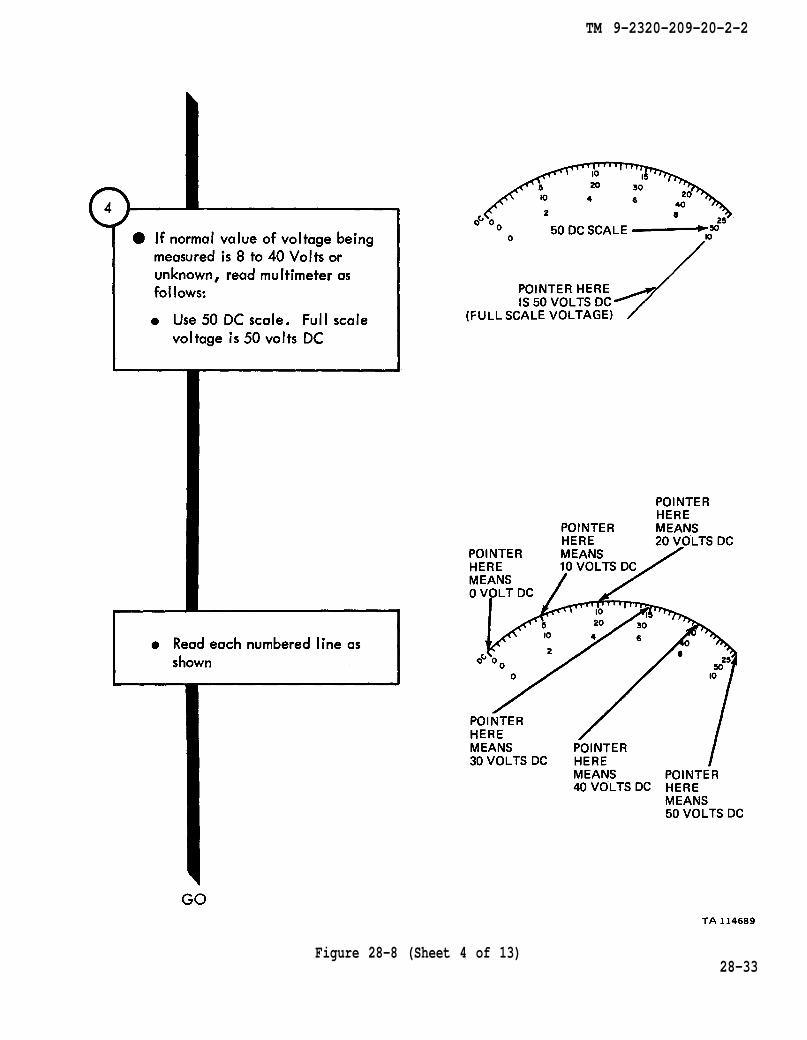
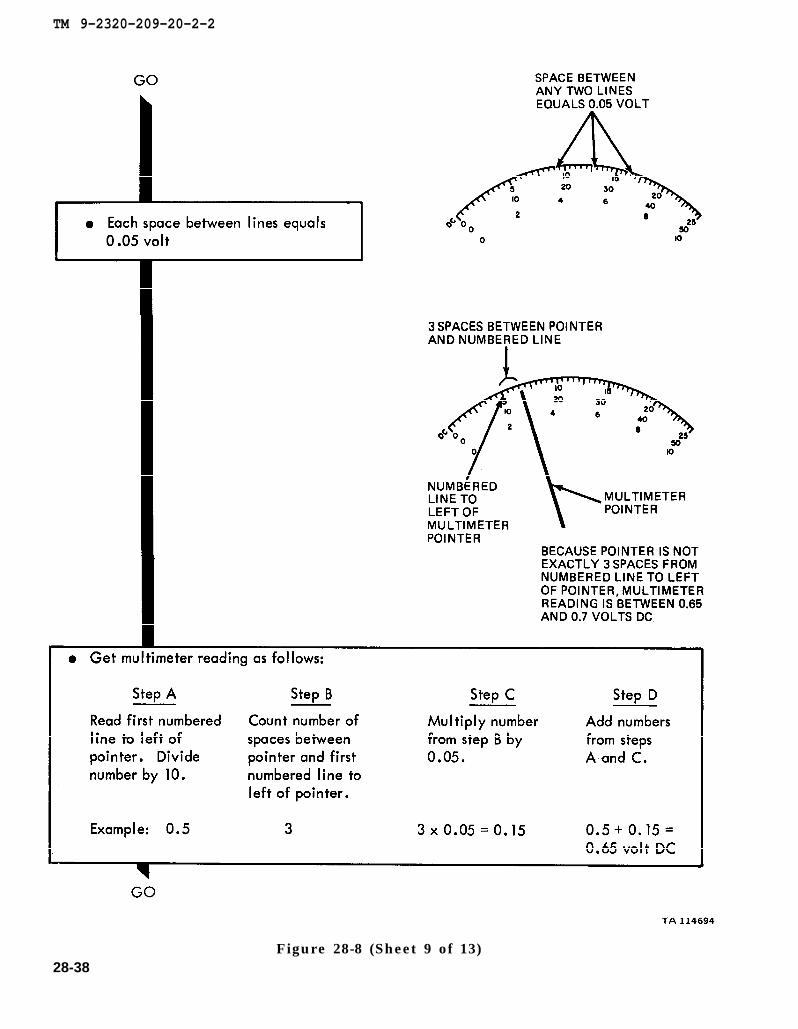
28-30Figure 28-8 (Sheet 1 of 13)

TM 9-2320-209-20-2-2
Figure 28-8 (Sheet 2 of 13)28-31

TM 9-2320-209-20-2-2
28-32Figure 28-8 (Sheet 3 of 13)
TM 9-2320-209-20-2-2
Figure 28-8 (Sheet 4 of 13)28-33
TM 9-2320-209-20-2-2
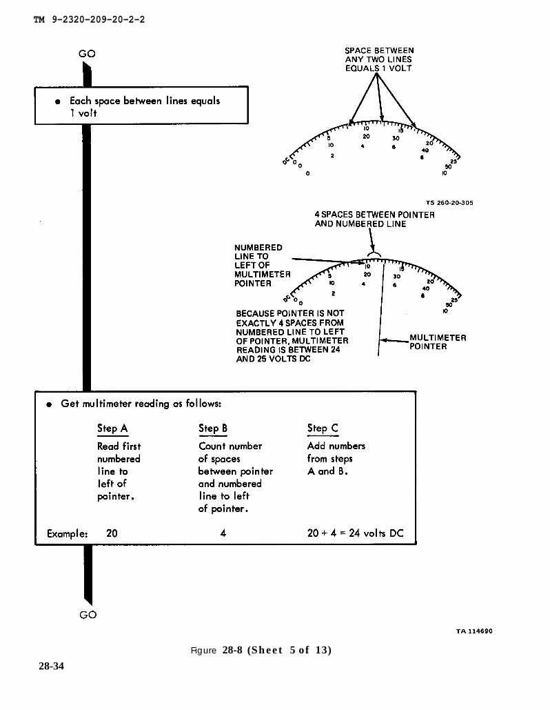
Figure 28-8 (Sheet 5 of 13)28-34
TM 9-2320-209-20-2-2
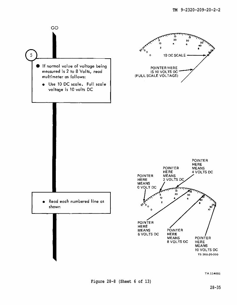
Figure 28-8 (Sheet 6 of 13)28-35

TM 9-2320-209-20-2-2
Figure 28-8 (Sheet 7 of 13)
28-36
TM 9-2320-209-20-2-2
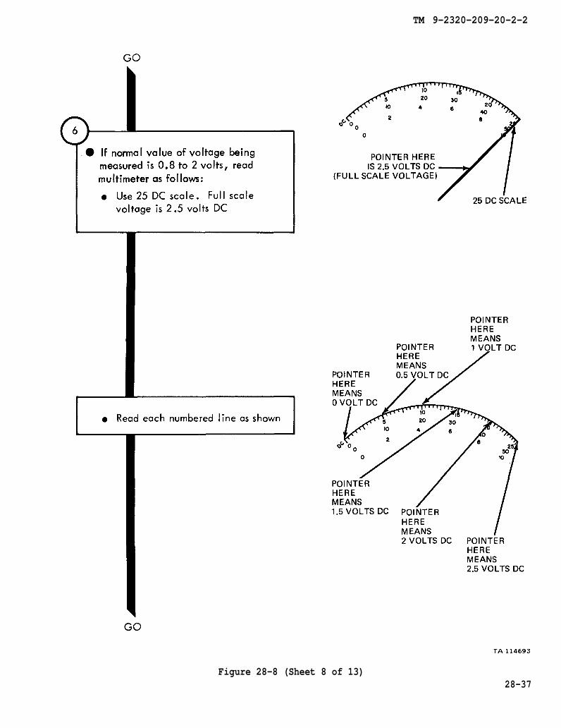
Figure 28-8 (Sheet 8 of 13)28-37
TM 9-2320-209-20-2-2
28-38Figure 28-8 (Sheet 9 of 13)

TM 9-2320-209-20-2-2
Figure 28-8 (Sheet 10 of 13)28-39
TM 9-2320-209-20-2-2
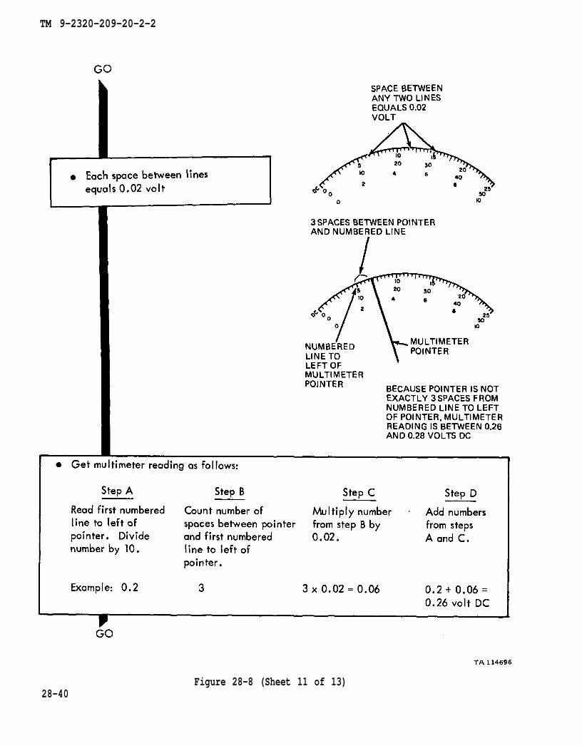
Figure 28-8 (Sheet 11 of 13)28-40

TM 9-2320-209-20-2-2
Figure 28-8 (Sheet 12 of 13)2 8 - 4 1
TM 9-2320-209-20-2-2
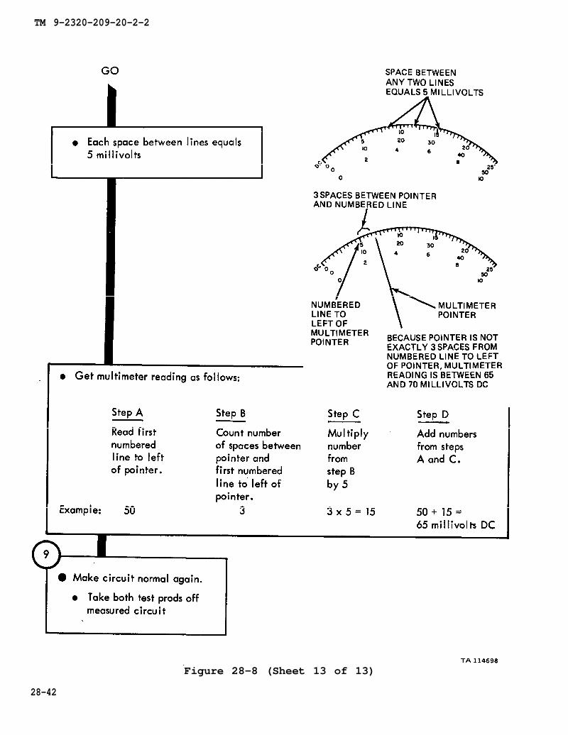
Figure 28-8 (Sheet 13 of 13)
28-42

TM 9-2320-209-20-2-2
Figure 28-9 (Sheet 1 of 4)28-43
TM 9-2320-209-20-2-2
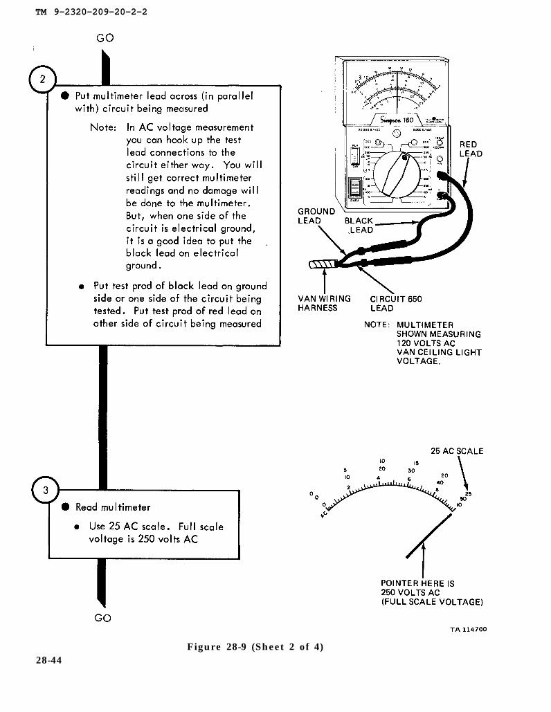
Figure 28-9 (Sheet 2 of 4)28-44
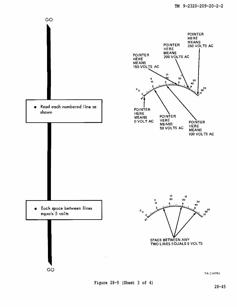
TM 9-2320-209-20-2-2
Figure 28-9 (Sheet 3 of 4)28-45
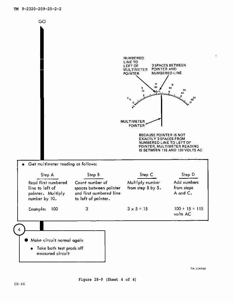
TM 9-2320-209-20-2-2
Figure 28-9 (Sheet 4 of 4)28-46
TM 9-2320-209-20-2-2
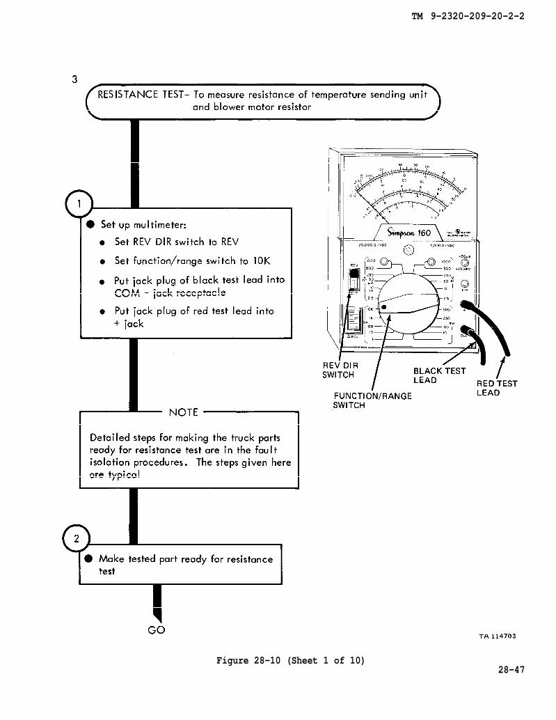
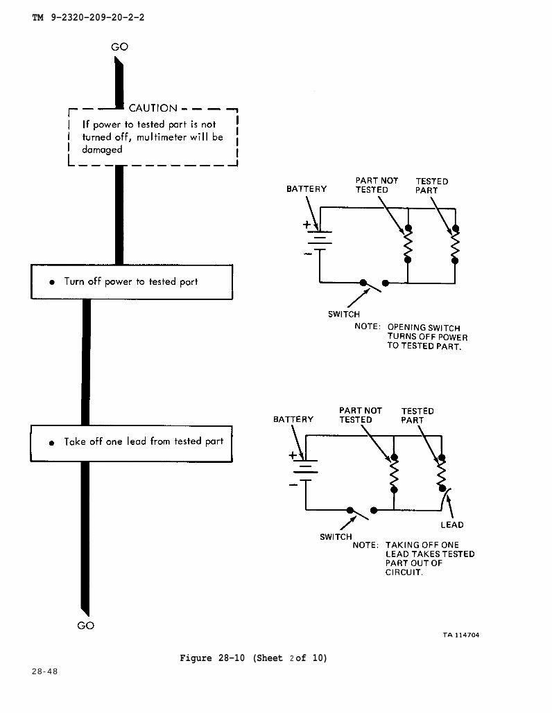
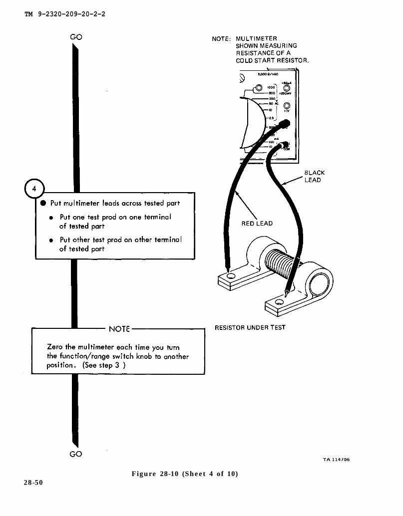
Figure 28-10 (Sheet 1 of 10)28-47
TM 9-2320-209-20-2-2
28-48
Figure 28-10 (Sheet 2 of 10)

TM 9-2320-209-20-2-2
Figure 28-10 (Sheet 3 of 10)
28-49
TM 9-2320-209-20-2-2
Figure 28-10 (Sheet 4 of 10)28-50
TM 9-2320-209-20-2-2
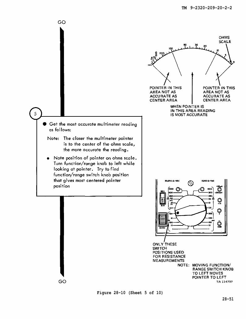
Figure 28-10 (Sheet 5 of 10)28-51
TM 9-2320-209-20-2-2
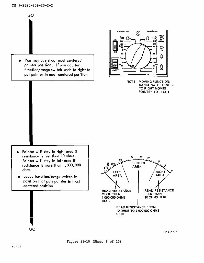
Figure 28-10 (Sheet 6 of 10)28-52

TM 9-2320-209-20-2-2
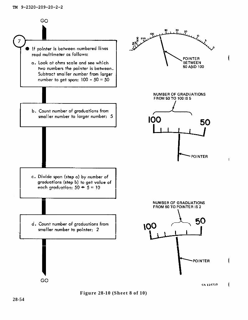
Figure 28-10 (Sheet 7 of 10)28-53
TM 9-2320-209-20-2-2
Figure 28-10 (Sheet 8 of 10)28-54
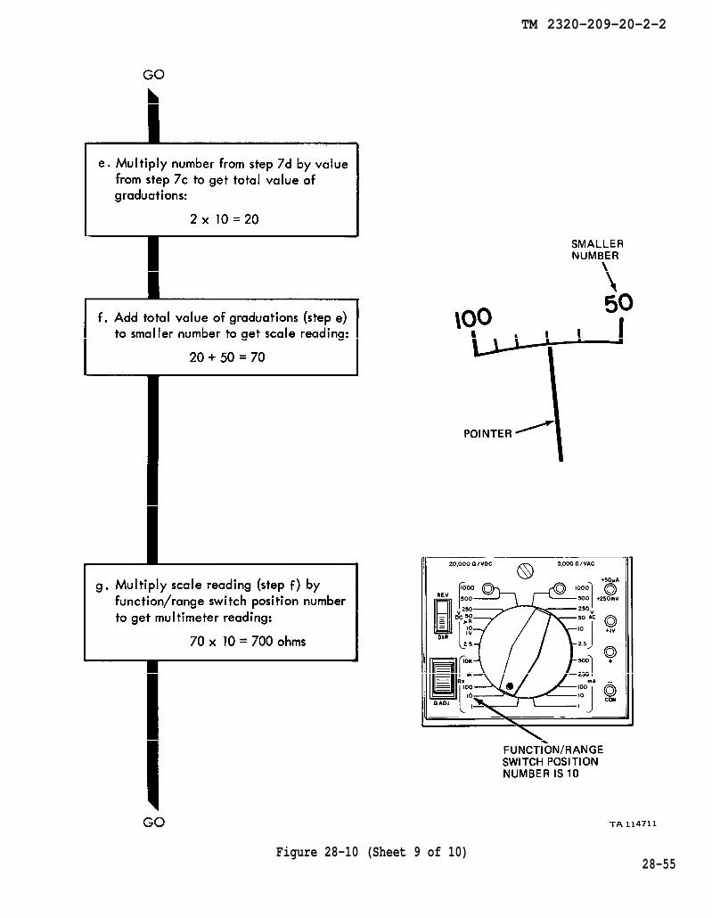
TM 2320-209-20-2-2
Figure 28-10 (Sheet 9 of 10)28-55

Figure 28-10
TM 9-2320-209-20-2-2
Figure 28-11 (Sheet 1 of 6)28-56
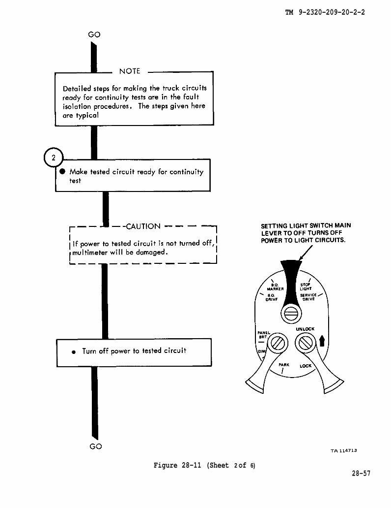
TM 9-2320-209-20-2-2
Figure 28-11 (Sheet 2 of 6)28-57
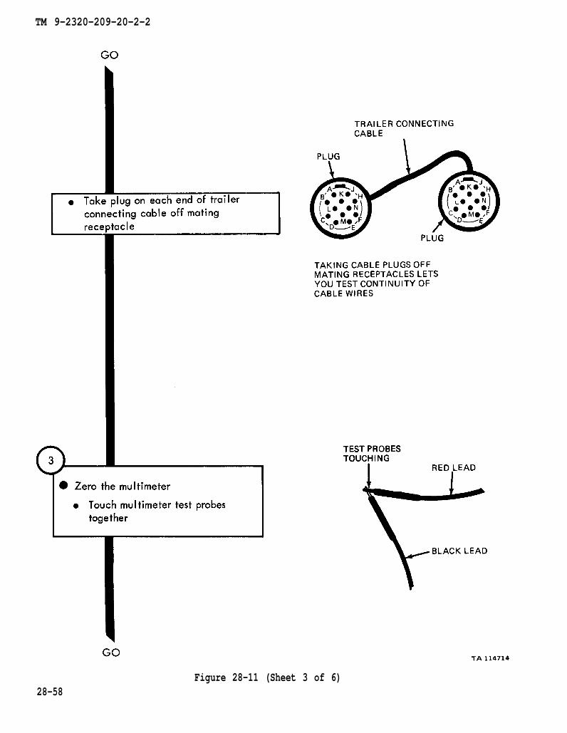
TM 9-2320-209-20-2-2
Figure 28-11 (Sheet 3 of 6)28-58

TM 9-2320-209-20-2-2
Figure 28-11 (Sheet 4 of 6)28-59
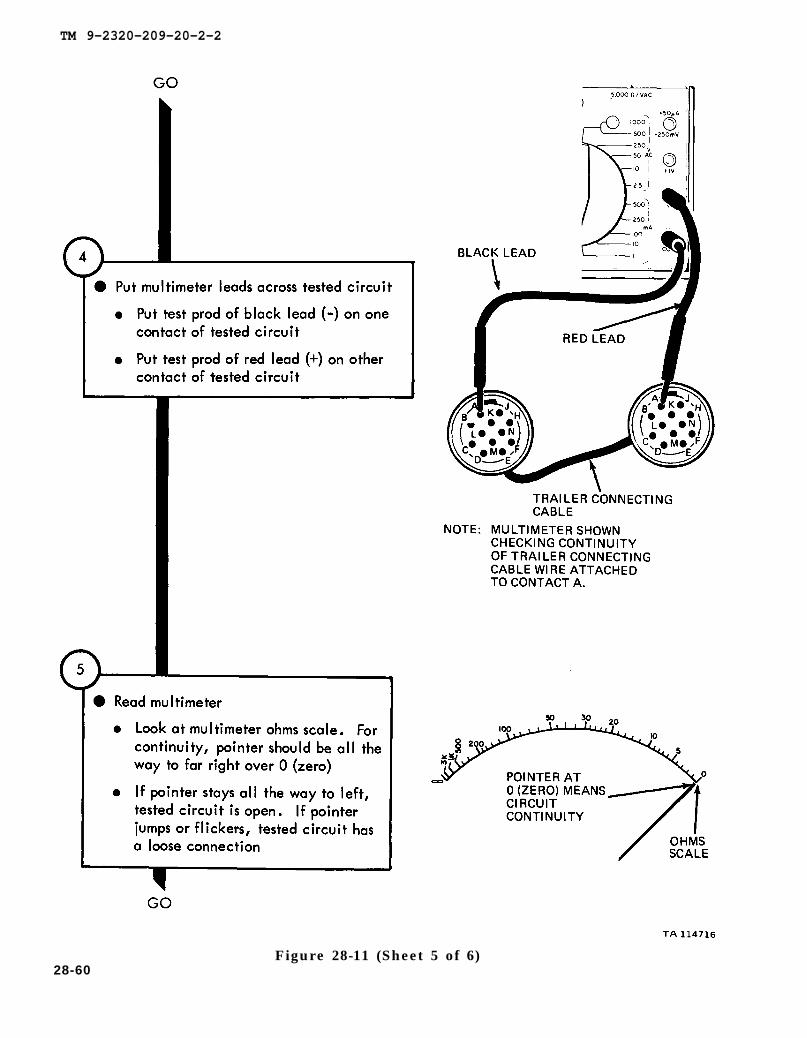
TM 9-2320-209-20-2-2
28-60Figure 28-11 (Sheet 5 of 6)

Figure 28-11
TM 9-2320-209-20-2-2
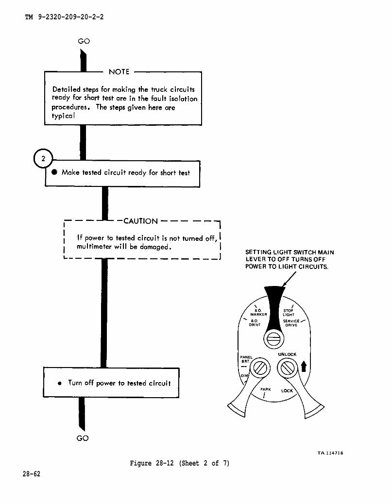
Figure 28-12 (Sheet 1 of 7)
28-61
TM 9-2320-209-20-2-2
Figure 28-12 (Sheet 2 of 7)28-62

TM 9-2320-209-20-2-2
Figure 28-12 (Sheet 3 of 7)28-63

TM 9-2320-209-20-2-2
28-64Figure 28-12 (Sheet 4 of 7)

TM 9-2320-209-20-2-2
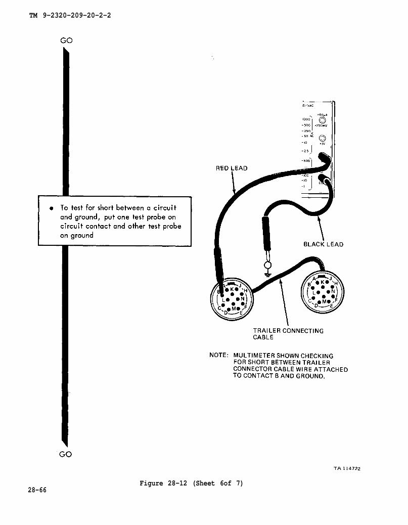
Figure 28-12 (Sheet 5 of 7)28-65
TM 9-2320-209-20-2-2
28-66Figure 28-12 (Sheet 6of 7)
TM 9-2320-209-20-2-2
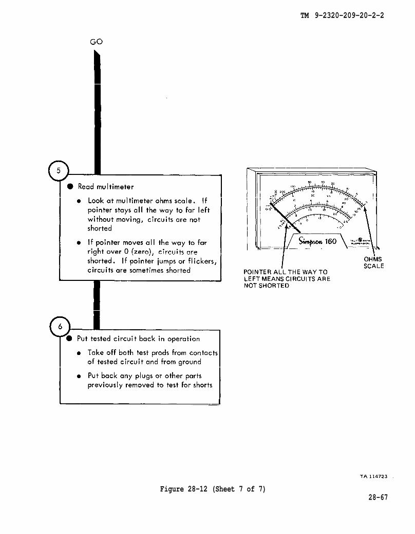
Figure 28-12 (Sheet 7 of 7)28-67
TM 9-2320-209-20-2-2
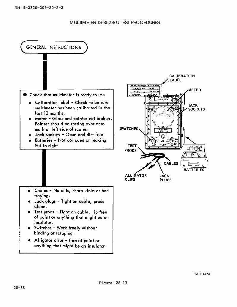
MULTIMETER TS-352B/U TEST PROCEDURES
Figure 28-1328-68
TM 9-2320-209-20-2-2
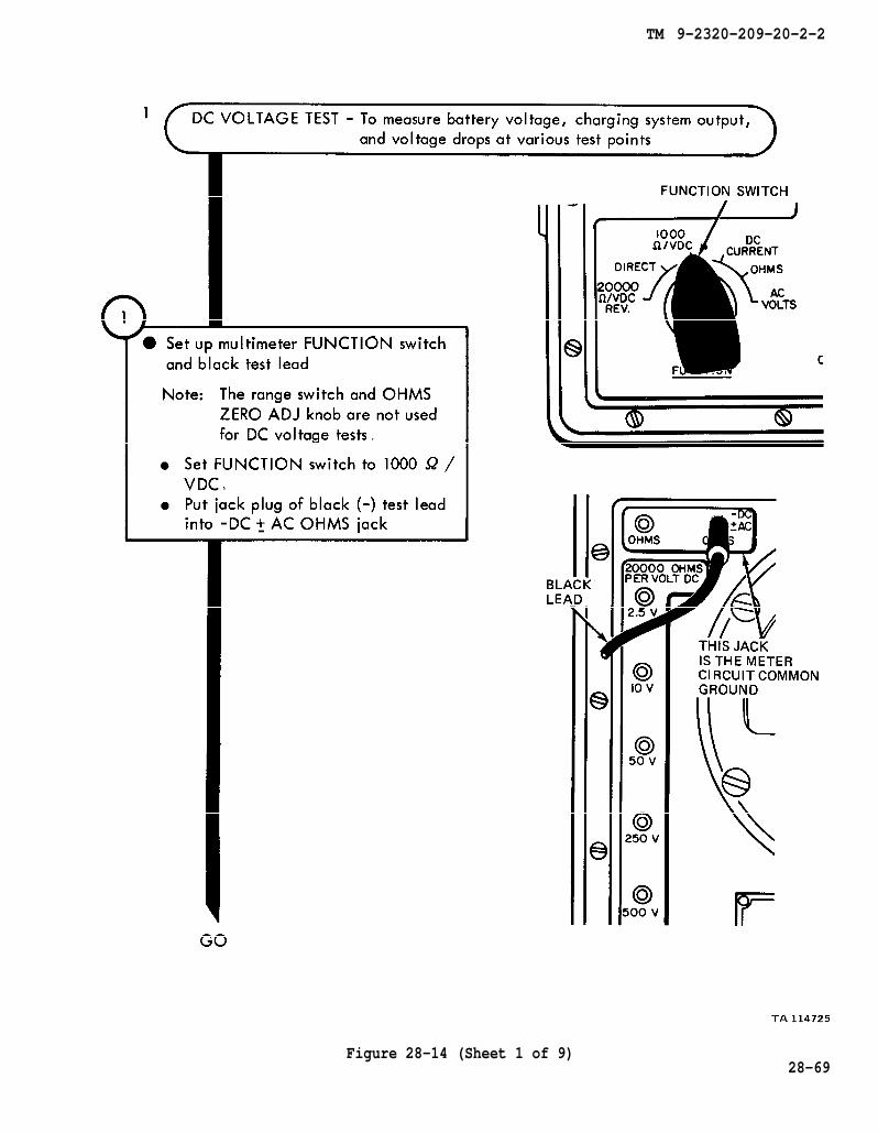
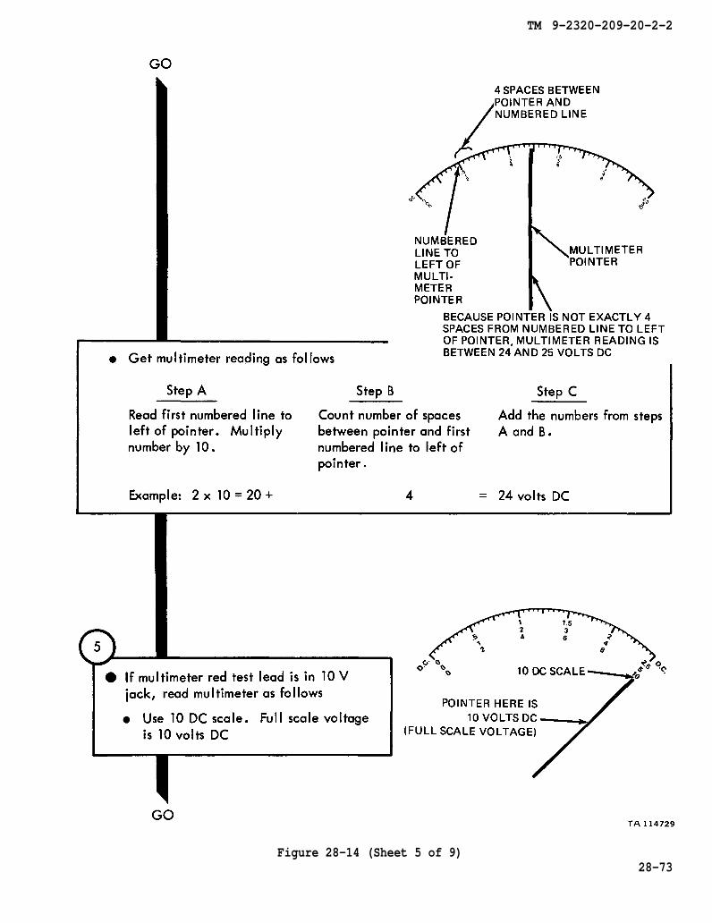
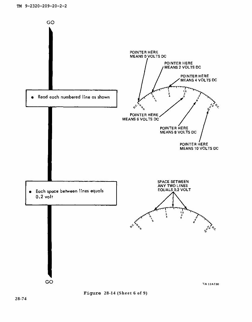
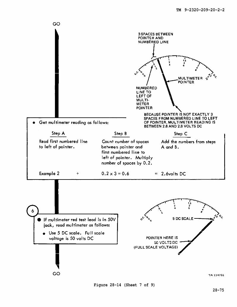
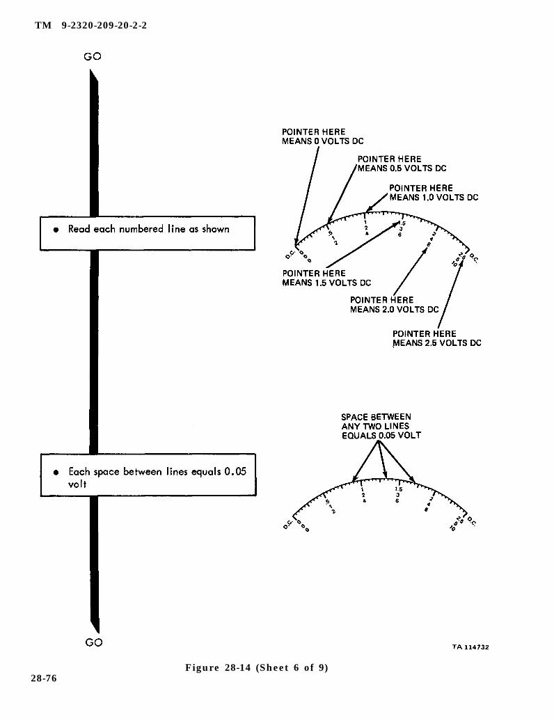
Figure 28-14 (Sheet 1 of 9)28-69
TM 9-2320-209-20-2-2
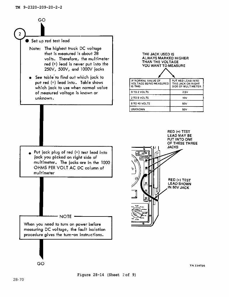
Figure 28-14 (Sheet 2 of 9)28-70
TM 9-2320-209-20-2-2
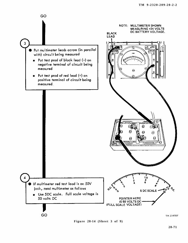
Figure 28-14 (Sheet 3 of 9)
28-71
TM 9-2320-209-20-2-2
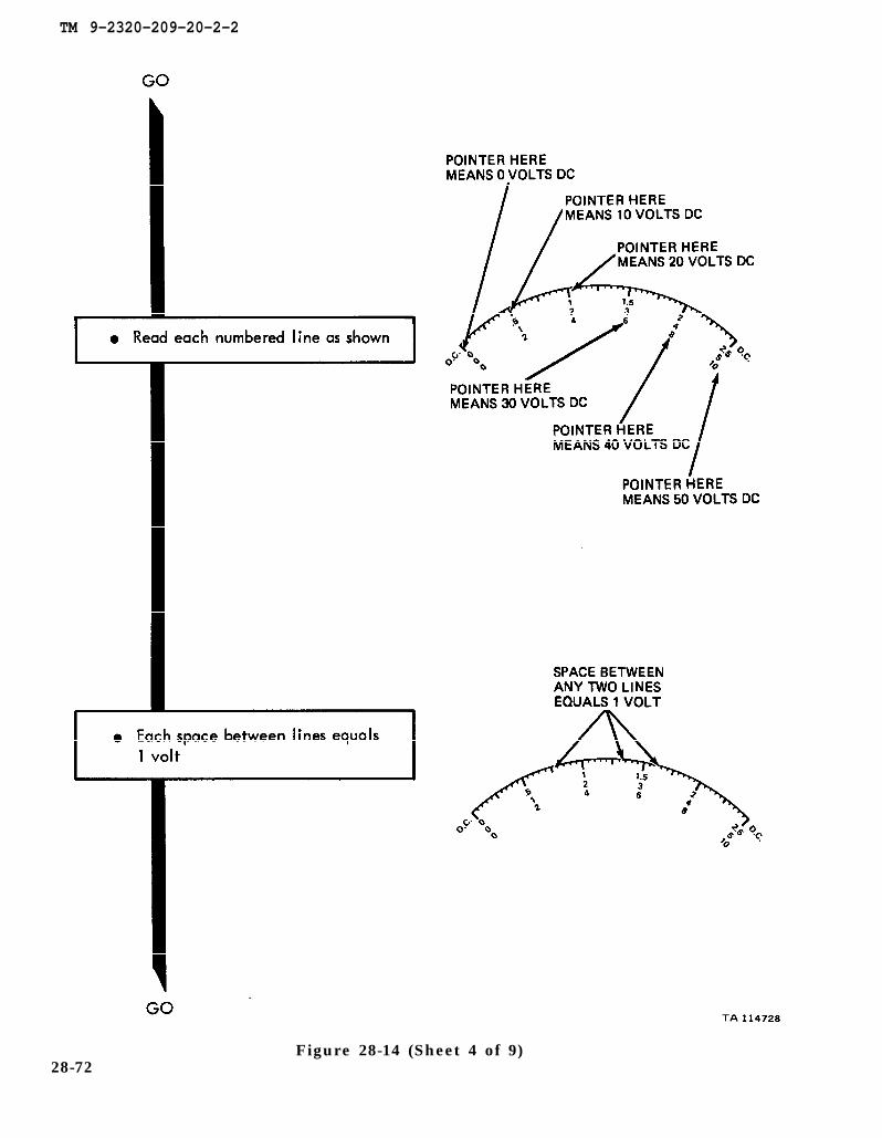
Figure 28-14 (Sheet 4 of 9)28-72
TM 9-2320-209-20-2-2
Figure 28-14 (Sheet 5 of 9)28-73
TM 9-2320-209-20-2-2
Figure 28-14 (Sheet 6 of 9)28-74
TM 9-2320-209-20-2-2
Figure 28-14 (Sheet 7 of 9)28-75
TM 9-2320-209-20-2-2
Figure 28-14 (Sheet 6 of 9)28-76
TM 9-2320-209-20-2-2
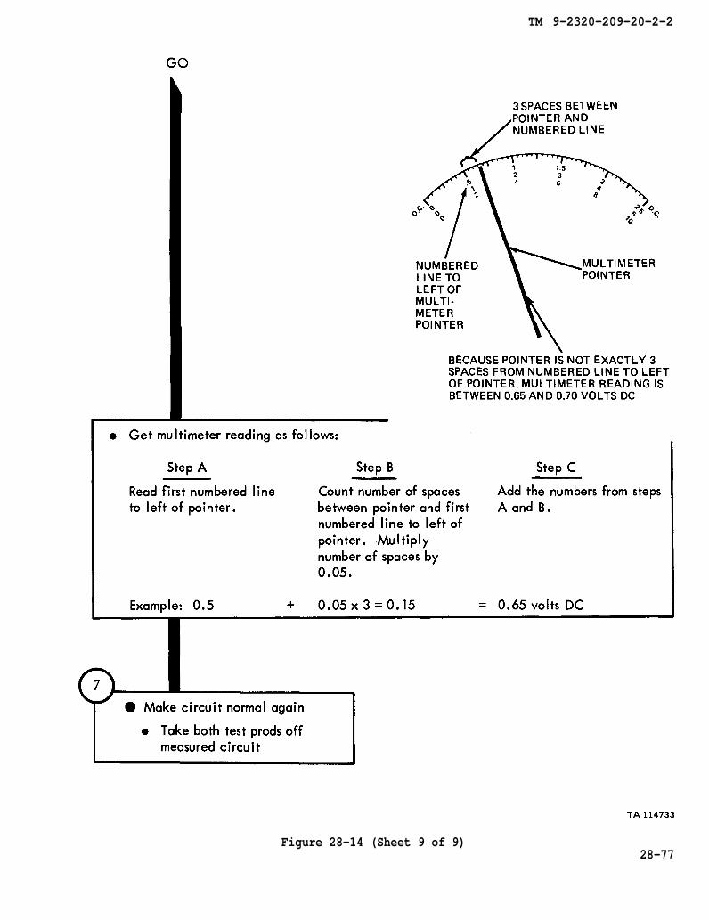
Figure 28-14 (Sheet 9 of 9)28-77
TM 9-2320-209-20-2-2
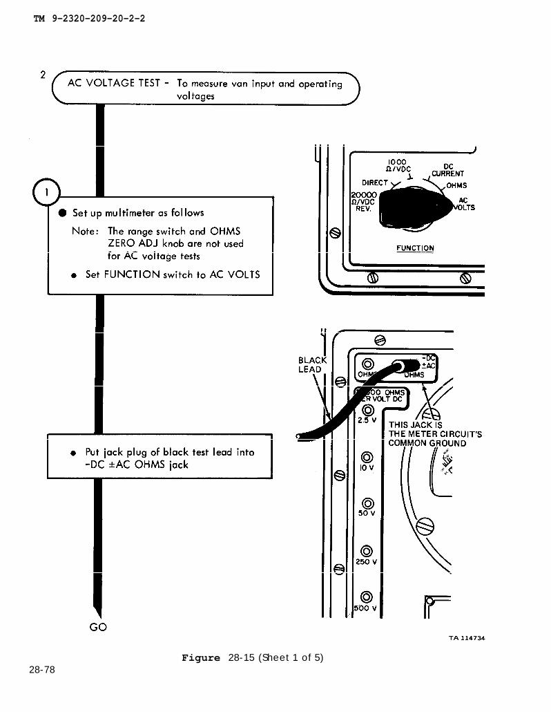
28-78Figure 28-15 (Sheet 1 of 5)
TM 9-2320-209-20-2-2
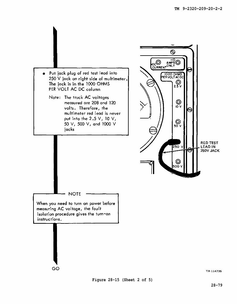
Figure 28-15 (Sheet 2 of 5)28-79

TM 9-2320-209-20-2-2
Figure 28-15 (Sheet 3 of 5)28-80

TM 9-2320-209-20-2-2
Figure 28-15 (Sheet 4 of 5)28-81
TM 9-2320-209-20-2-2
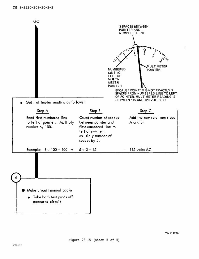
Figure 28-15 (Sheet 5 of 5)28-82

TM 9-2320-209-20-2-2
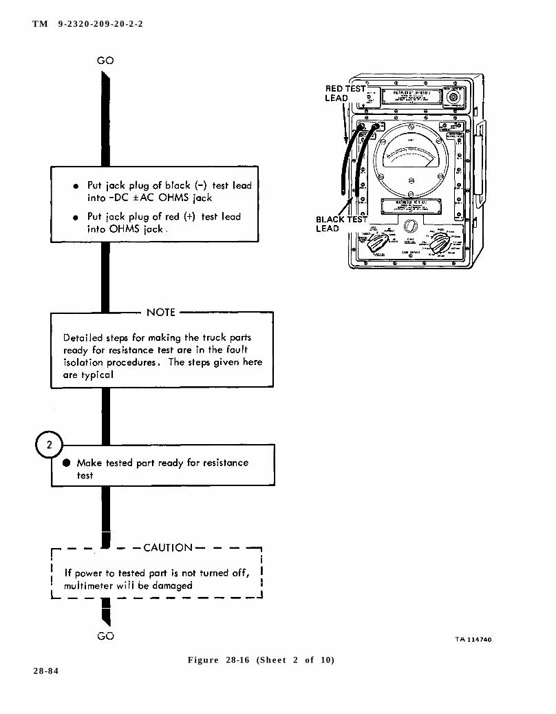
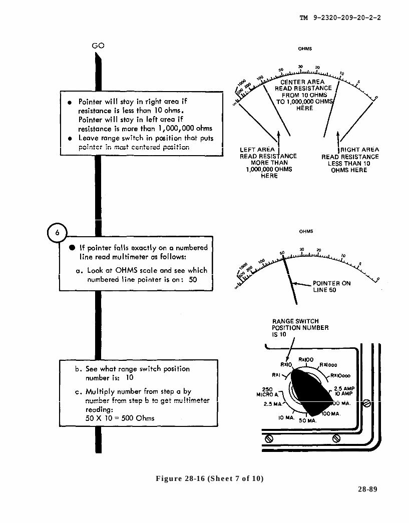
Figure 28-16 (Sheet 1 of 10)28-83
TM 9-2320-209-20-2-2
Figure 28-16 (Sheet 2 of 10)28-84
TM 9-2320-209-20-2-2
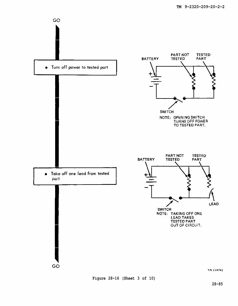
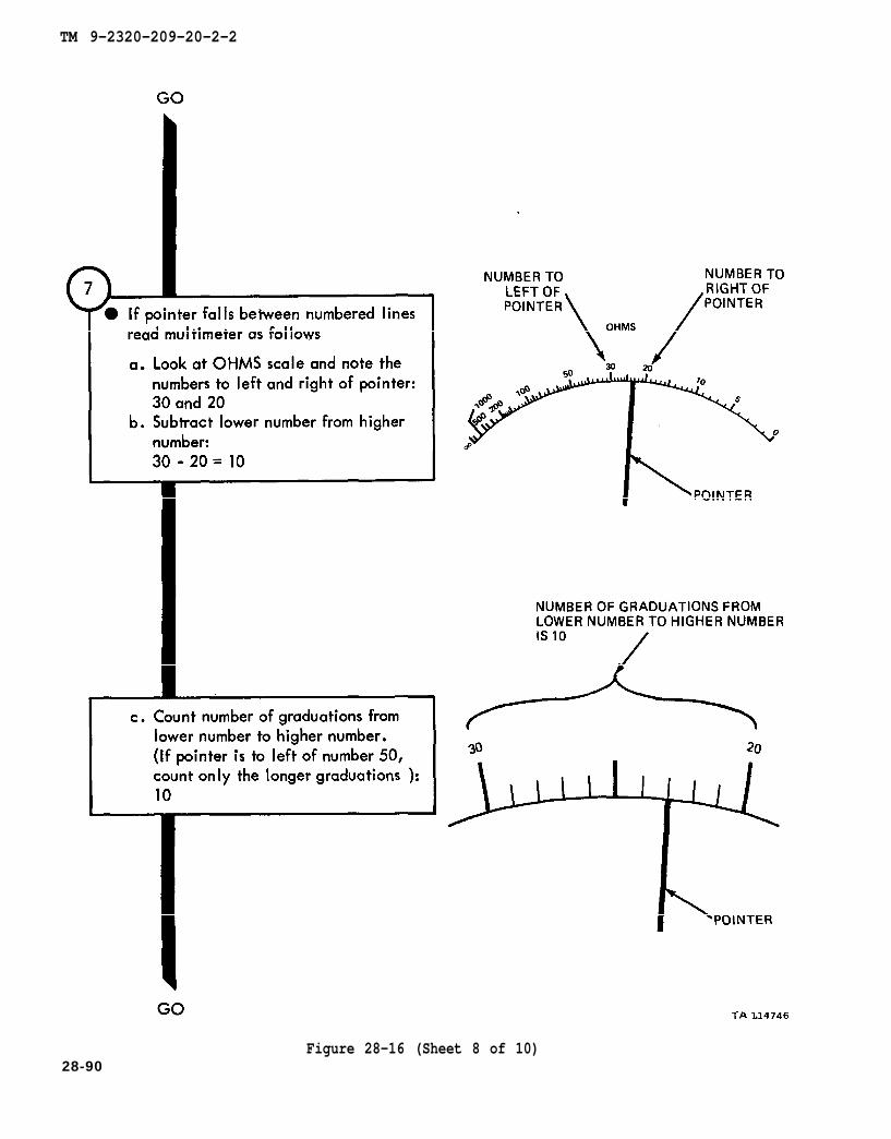
Figure 28-16 (Sheet 3 of 10)28-85

TM 9-2320-209-20-2-2
28-86Figure 28-16 (Sheet 4 of 10)
TM 9-2320-209-20-2-2
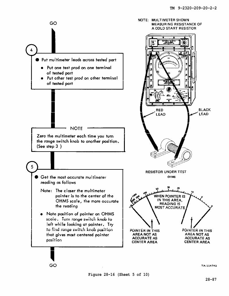
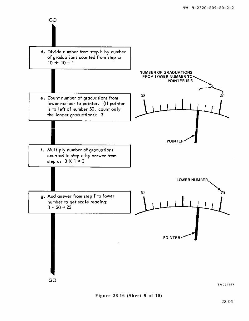
Figure 28-16 (Sheet 5 of 10)28-87
TM 9-2320-209-20-2-2
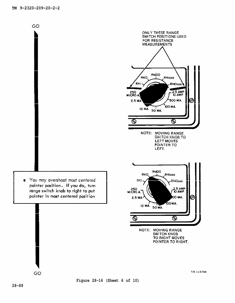
Figure 28-16 (Sheet 6 of 10)28-88
TM 9-2320-209-20-2-2
Figure 28-16 (Sheet 7 of 10)28-89
TM 9-2320-209-20-2-2
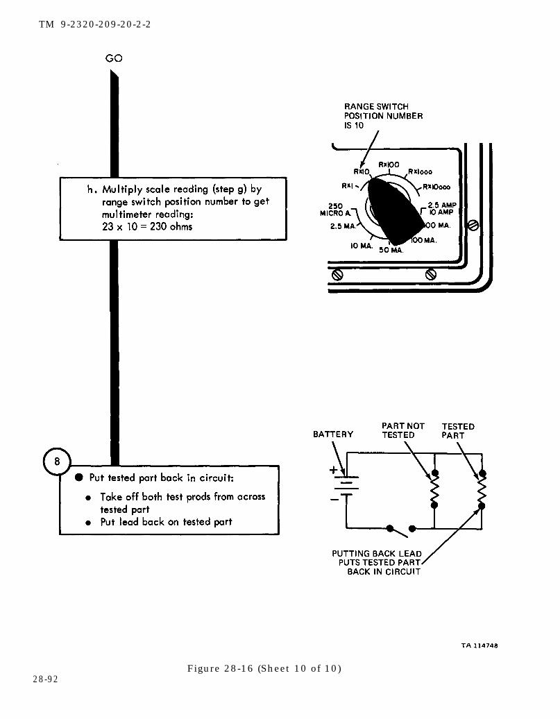
28-90Figure 28-16 (Sheet 8 of 10)
TM 9-2320-209-20-2-2
Figure 28-16 (Sheet 9 of 10)28-91
TM 9-2320-209-20-2-2
28-92Figure 28-16 (Sheet 10 of 10)

TM 9-2320-209-20-2-2
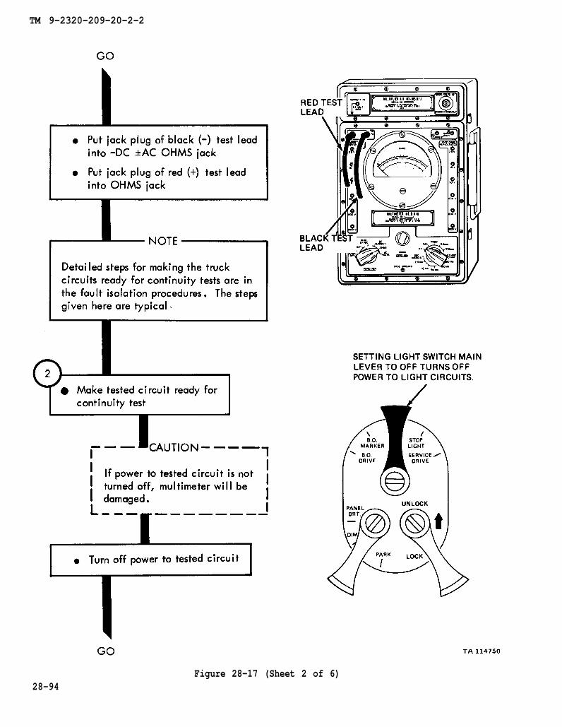
Figure 28-17 (Sheet 1 of 6)28-93
TM 9-2320-209-20-2-2
28-94Figure 28-17 (Sheet 2 of 6)
TM 9-2320-209-20-2-2
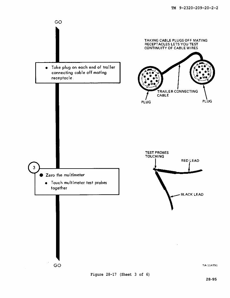
Figure 28-17 (Sheet 3 of 6)28-95
TM 9-2320-209-20-2-2
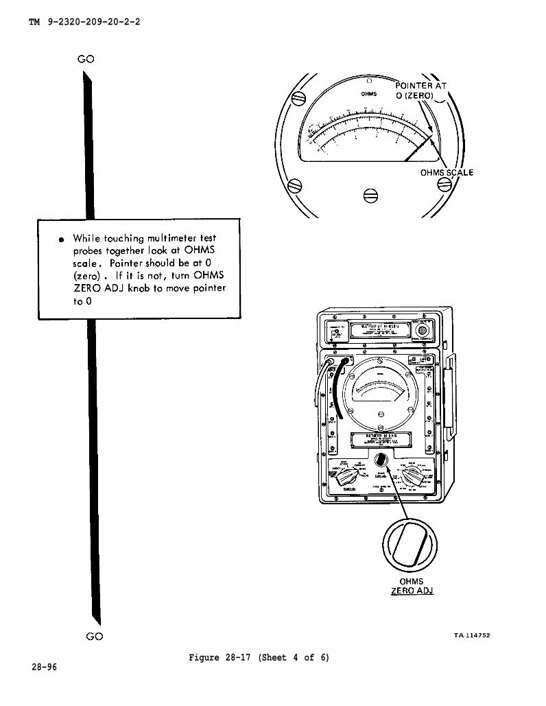
28-96Figure 28-17 (Sheet 4 of 6)
TM 9-2320-209-20-2-2
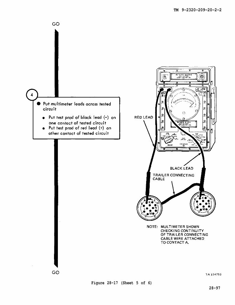
Figure 28-17 (Sheet 5 of 6)28-97
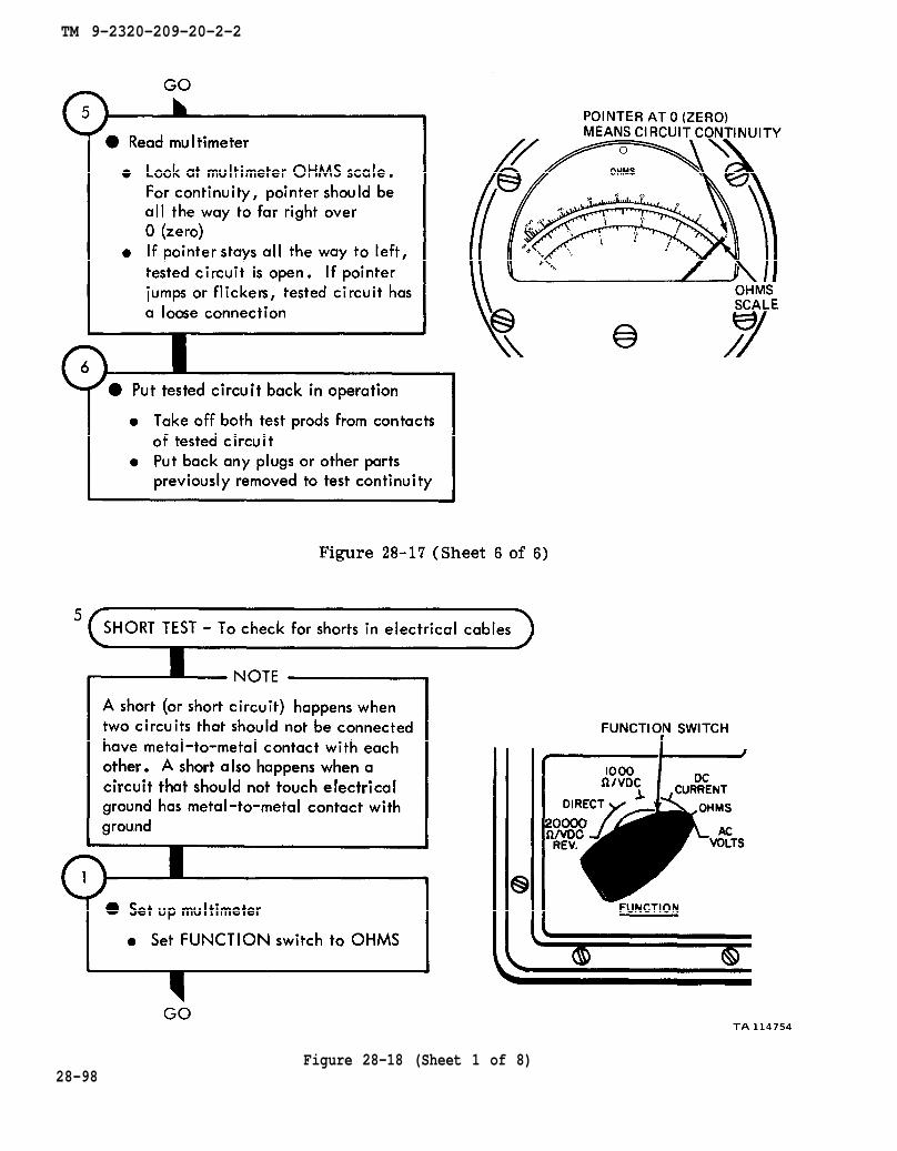
Figure 28-17
TM 9-2320-209-20-2-2
Figure 28-18 (Sheet 1 of 8)28-98
TM 9-2320-209-20-2-2
Figure 28-18 (Sheet 2 of 8)
28-99

TM 9-2320-209-20-2-2
28-100Figure 28-18 (Sheet 3 of 8)
TM 9-2320-209-20-2-2
Figure 28-18 (Sheet 4 of 8)
28-101
TM 9-2320-209-20-2-2
Figure 28-18 (Sheet 5 of 8)28-102
TM 9-2320-209-20-2-2
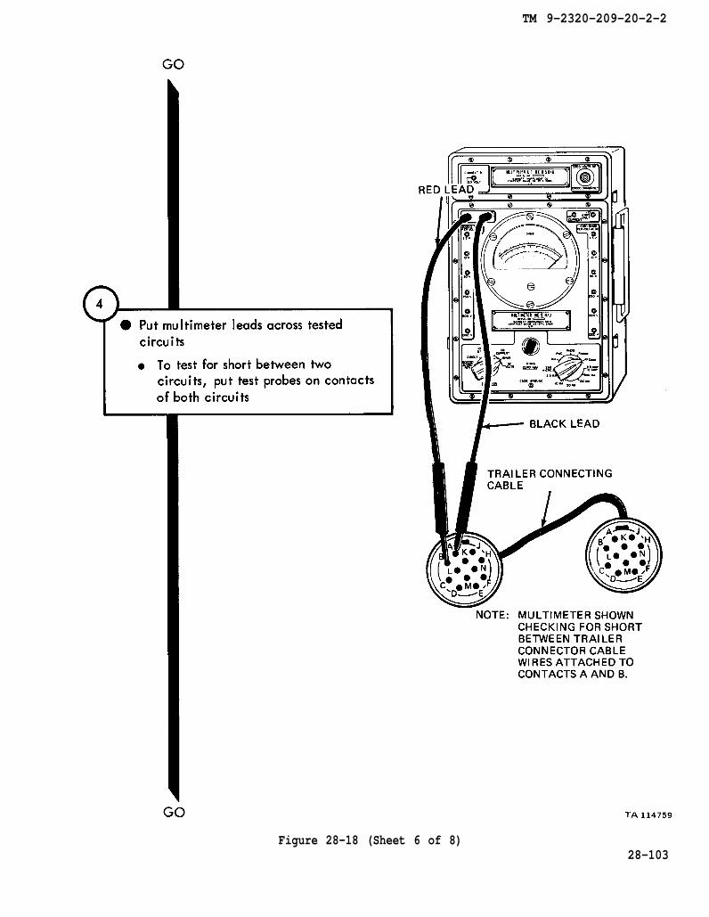
Figure 28-18 (Sheet 6 of 8)28-103

TM 9-2320-209-20-2-2
Figure 28-18 (Sheet 7 of 8)28-104

TM 9-2320-209-20-2-2
Figure 28-18 (Sheet 8 of 8)28-105/(28-106 blank)

TM 9-2320-209-20-2-2
CHAPTER 29
OPERATING AND PRELIMINARY PROCEDURES
29-1. EQUIPMENT ITEMS COVERED. This chapter gives equipment operating andpreliminary procedures for the system, for which there are authorized correctivemaintenance tasks at the organizational maintenance level.
29-2. EQUIPMENT ITEMS NOT COVERED. All equipment items for which correctivemaintenance is authorized at the organizational maintenance level are covered in thischapter.
29-1
TM 9-2320-209-20-2-2
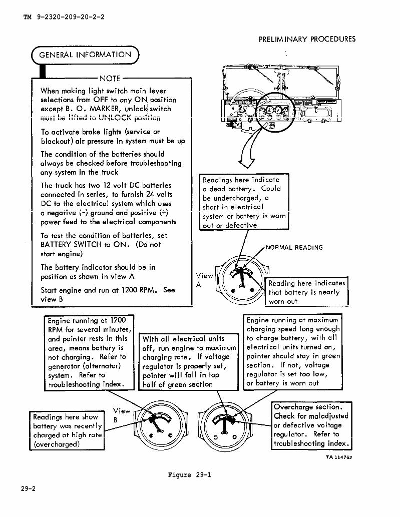
Figure 29-1
29-2

TM 9-2320-209-20-2-2
CHAPTER 30
ELECTRICAL SYSTEM CHECKOUT PROCEDURES
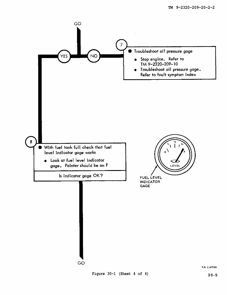
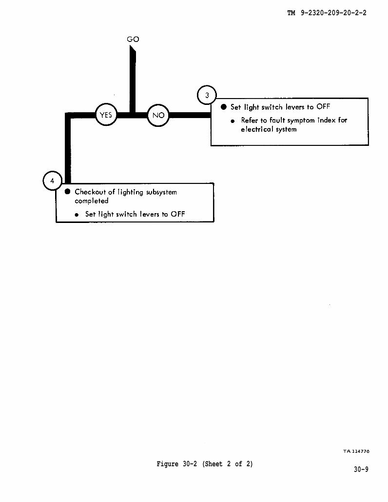
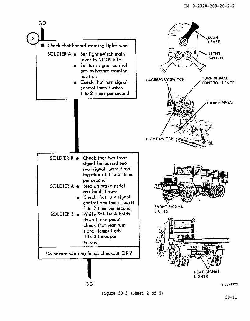
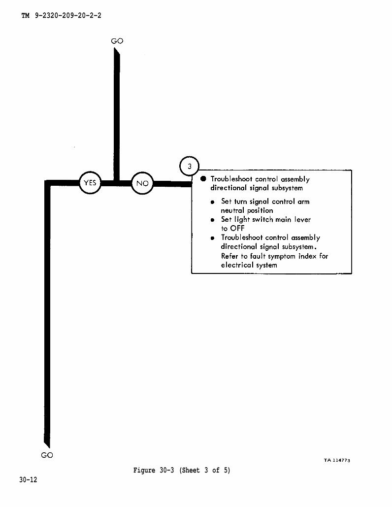
30-1. GENERAL. This chapter gives procedures for checking out the system aftertroubleshooting and repair have been done. Procedures are set up in flow chartform showing the checkout steps in order and referring to the fault symptom indexwhen the system does not check out.
30-1

TM 9-2320-209-10
TM 9-2320-209-20-2-2
Figure 30-1 (Sheet 1 of 6)
30-2

TM 9-2320-209-10
TM 9-2320-209-20-2-2
Figure 30-1 (Sheet 2 of 6)30-3
TM 9-2320-209-10
TM 9-2320-209-20-2-2
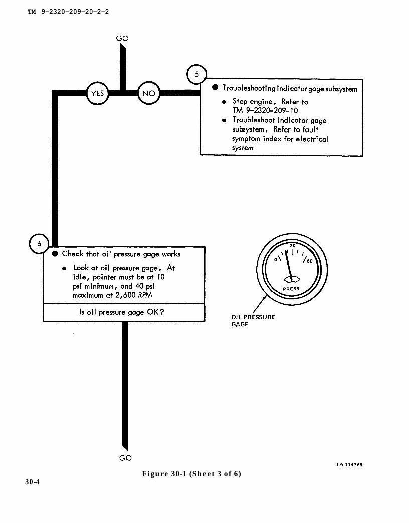
Figure 30-1 (Sheet 3 of 6)30-4
TM 9-2320-209-10
TM 9-2320-209-20-2-2
Figure 30-1 (Sheet 4 of 6) 3 0 - 5

TM 9-2320-209-10
TM 9-2320-209-20-2-2
30-6Figure 30-1 (Sheet 5 of 6)

TM 9-2320-209-10
TM 9-2320-209-10
TM 9-2320-209-20-2-2
Figure 30-1 (Sheet 6 of 6)30-7

TM 9-2320-209-10
TM 9-2320-209-10
TM 9-2320-209-20-2-2
30-8Figure 30-2 (Sheet 1 of 2)
TM 9-2320-209-20-2-2
Figure 30-2 (Sheet 2 of 2)30-9

TM 9-2320-209-10
TM 9-2320-209-20-2-2
30-10Figure 30-3 (Sheet 1 of 5)
TM 9-2320-209-20-2-2
Figure 30-3 (Sheet 2 of 5)30-11
TM 9-2320-209-20-2-2
Figure 30-3 (Sheet 3 of 5)30-12

TM 9-2320-209-20-2-2
Figure 30-3 (Sheet 4 of 5)30-13

TM 9-2320-209-20-2-2
Figure 30-3 (Sheet 5 of 5)30-14

TM 9-2320-209-20-2-2
CHAPTER 31
TRANSMISSION SYSTEM TROUBLESHOOTING
31-1. EQUIPMENT ITEMS COVERED. This chapter gives equipment troubleshootingprocedures for the transmission system, for which there are authorized correctivemaintenance tasks at the organizational maintenance level.
31-2. EQUIPMENT ITEMS NOT COVERED. All equipment items for which correctivemaintenance is authorized at the organizational maintenance level are covered in thischapter.
31-1
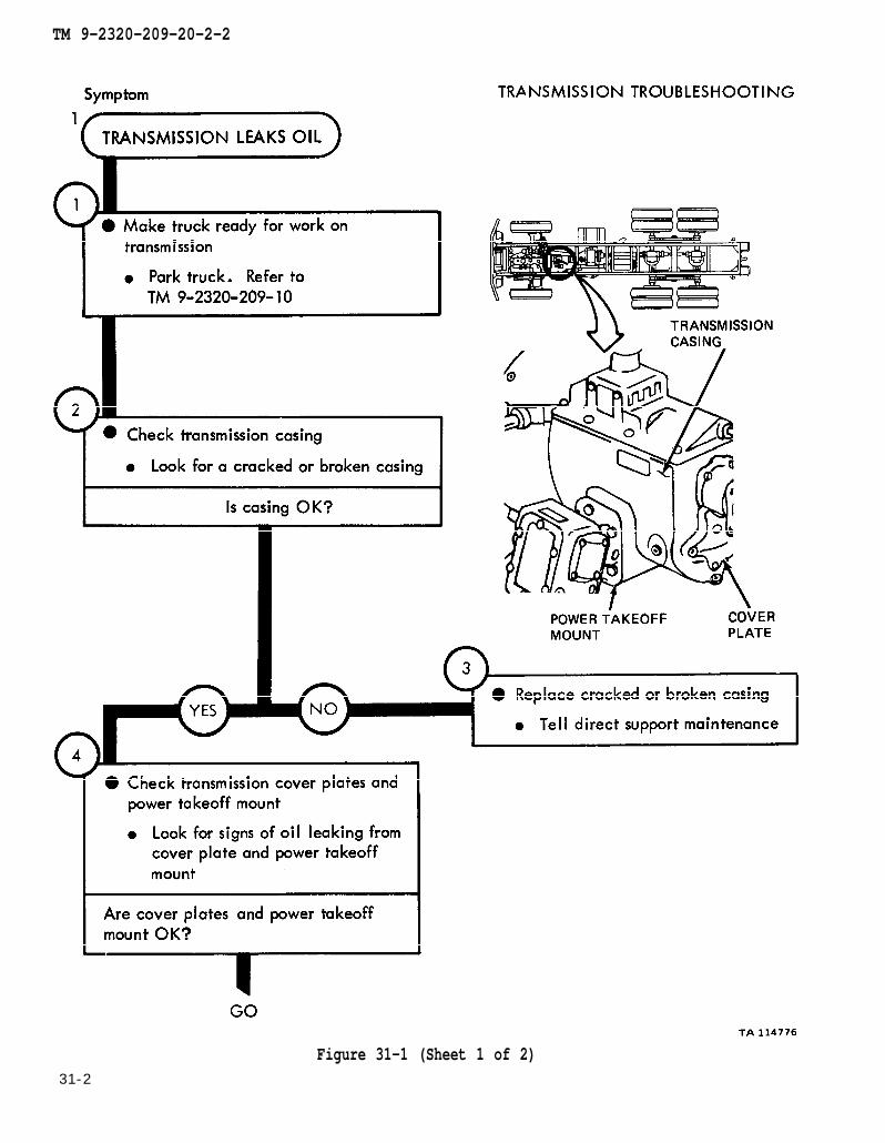
TM 9-2320-209-10
TM 9-2320-209-20-2-2
31-2
Figure 31-1 (Sheet 1 of 2)

TM 9-2320-209-10
LO 9-2320-209-12/1
TM 9-2320-209-20-2-2
Figure 31-1 (Sheet 2 of 2)
31-3
TM 9-2320-209-10
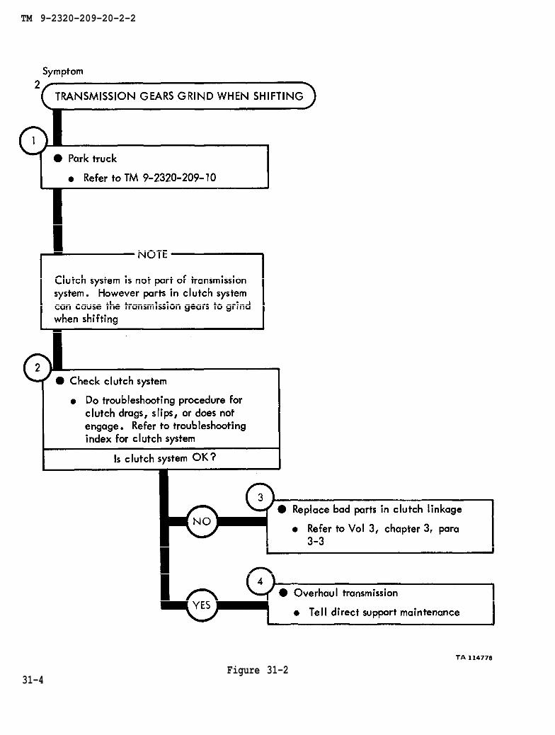
chapter 3 para 3-3
TM 9-2320-209-20-2-2
31-4Figure 31-2

TM 9-2320-209-20-2-2
CHAPTER 32
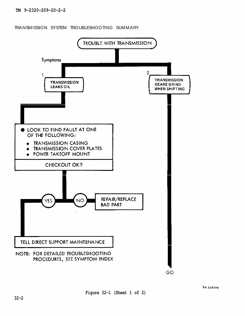
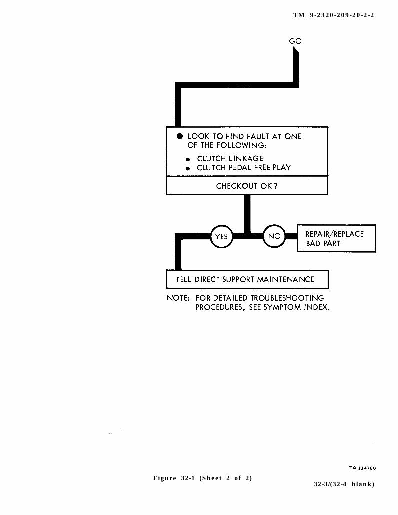
TRANSMISSION SYSTEM TROUBLESHOOTING SUMMARY
32-1. GENERAL. This chapter gives a summary of troubleshooting procedures givenin chapter 31 for the transmission system.
32-2. PROCEDURES. The summary in this chapter covers all fault symptoms foundin the detailed troubleshooting procedures. Chapter 7 outlines a sample troubleshoot-ing procedure. The summary procedures are based on the “what-to-do” portions ofthe detailed procedures and do not include the “how-to-do-it” instructions. Warn-ings, cautions, and notes are given where needed.
32-1
TM 9-2320-209-20-2-2
TRANSMISSION SYSTEM TROUBLESHOOTING SUMMARY
32-2Figure 32-1 (Sheet 1 of 2)
TM 9-2320-209-20-2-2
Figure 32-1 (Sheet 2 of 2) 32-3/(32-4 blank)

TM 9-2320-209-20-2-2
CHAPTER 33
TRANSFER SYSTEM TROUBLESHOOTING
33-1. EQUIPMENT ITEMS COVERED. This chapter gives equipment troubleshootingprocedures for the transfer system, for which there are authorized corrective mainte-nance tasks at the organizational maintenance level.
33-2. EQUIPMENT ITEMS NOT COVERED. All equipment items for which correctivemaintenance is authorized at the organizational maintenance level are covered in thischapter.
33-1

TM 9-2320-209-10
TM 9-2320-209-20-2-2
33-2Figure 33-1 (Sheet 1 of 2)

TM 9-2320-209-10
LO 9-2320-209-12/1
TM 9-2320-209-20-2-2
Figure 33-1 (Sheet 2 of 2)
33-3
TM 9-2320-209-10
chapter 18 para 18-5
chapter 9
para 9-3
TM 9-2320-209-20-2-2
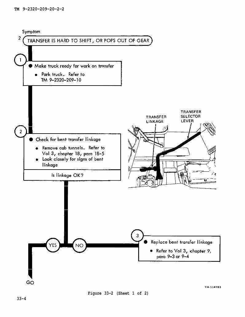
Figure 33-2 (Sheet 1 of 2)33-4

LO 9-2320-209-12/1
para 9-3
chapter 9
TM 9-2320-209-20-2-2
Figure 33-2 (Sheet 2 of 2)3 3 - 5

TM 9-2320-209-10
TM 9-2320-209-20-2-2
33-6Figure 33-3 (Sheet 1 of 5)

TM 9-2320-209-20-2-2
Figure 33-3 (Sheet 2 of 5)3 3 - 7
chapter 2 para 2-4
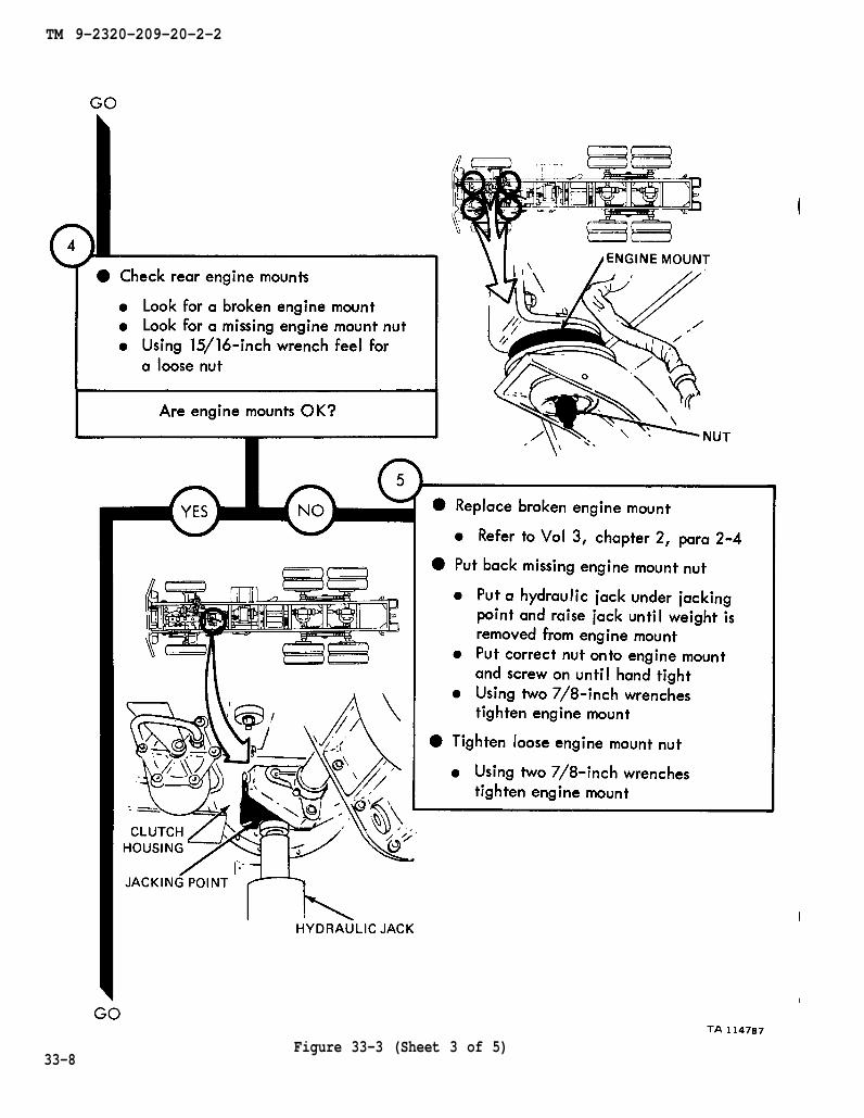
TM 9-2320-209-20-2-2
33-8Figure 33-3 (Sheet 3 of 5)
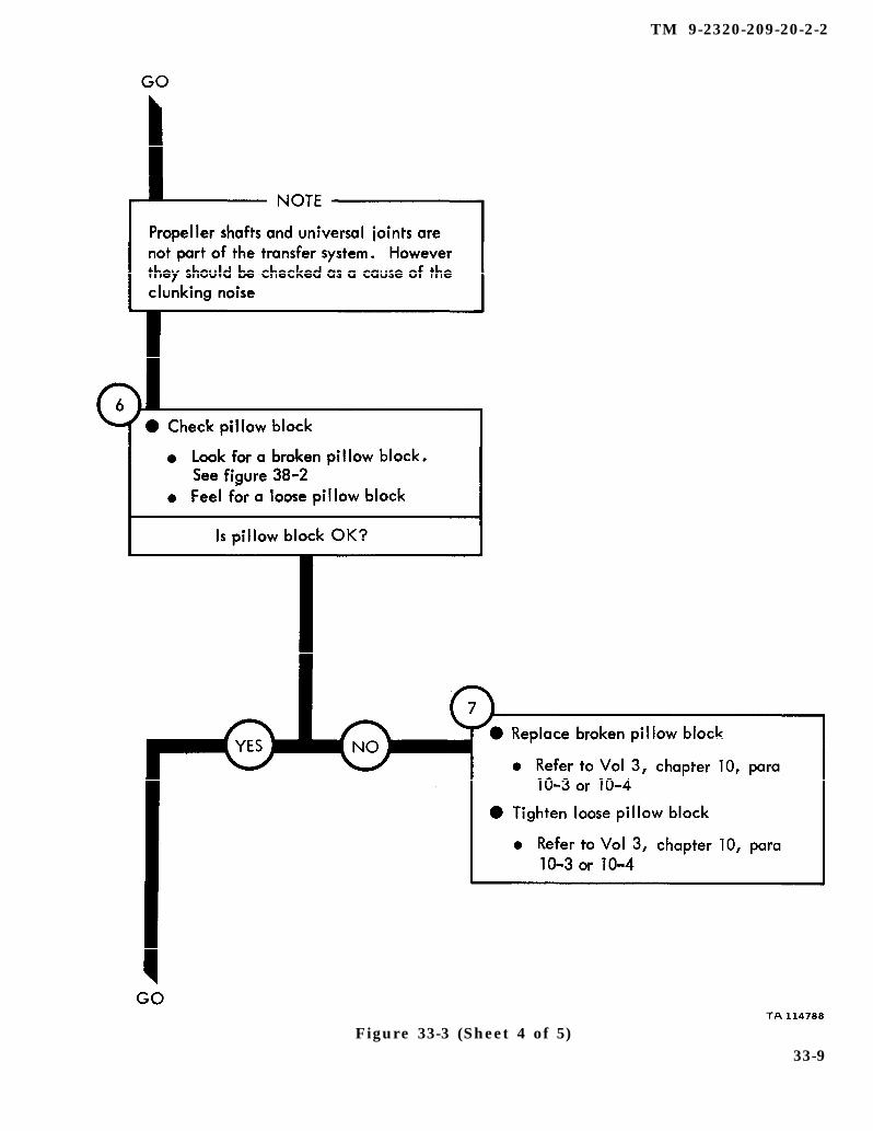
figure 38-2
chapter 10 para 10-3
chapter 10 para 10-3
TM 9-2320-209-20-2-2
Figure 33-3 (Sheet 4 of 5)33-9
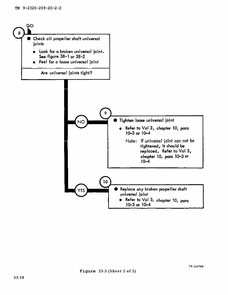
figure 38-1
chapter 10 para 10-3
chapter 10 para 10-3
chapter 10 para 10-3
TM 9-2320-209-20-2-2
Figure 33-3 (Sheet 5 of 5)
33-10
TM 9-2320-209-10
TM 9-2320-209-20-2-2
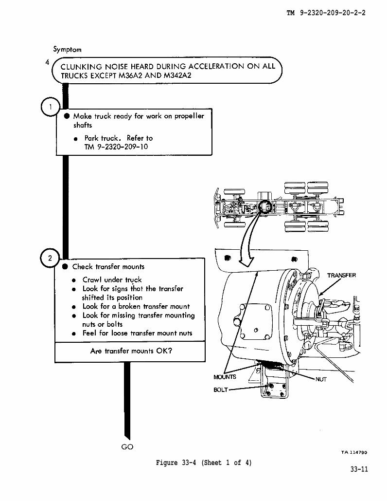
Figure 33-4 (Sheet 1 of 4)33-11
TM 9-2320-209-20-2-2
Figure 33-4 (Sheet 2 of 4)
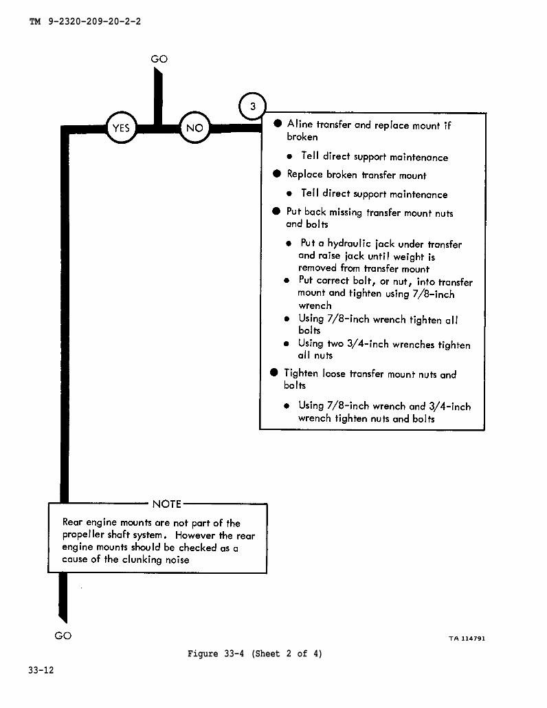
33-12
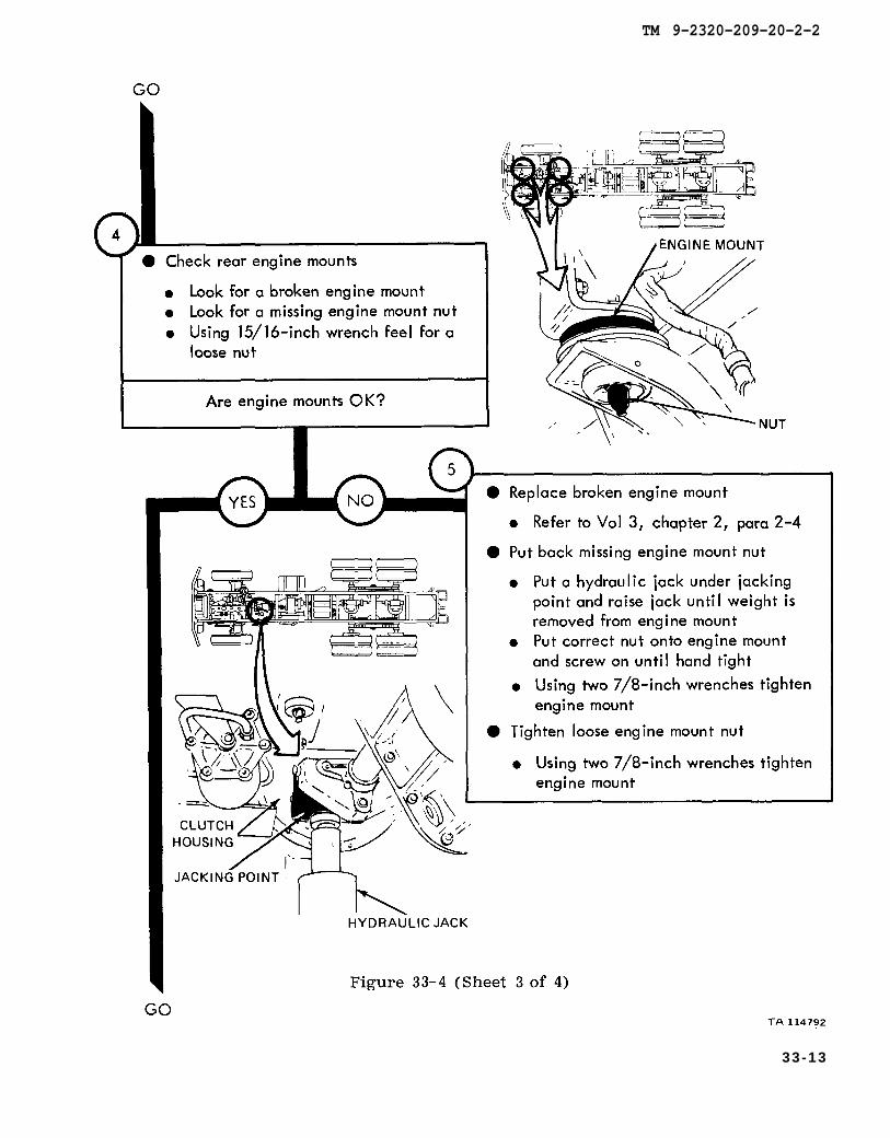
Figure 33-4
chapter 2 para 2-4
TM 9-2320-209-20-2-2
33-13

figure 38-1
chapter 10 para 10-3
chapter 10 para 10-3
chapter 10 para 10-3
TM 9-2320-209-20-2-2
Figure 33-4 (Sheet 4 of 4)33-14
TM 9-2320-209-20-2-2
CHAPTER 34
TRANSFER SYSTEM TROUBLESHOOTING SUMMARY
34-1. GENERAL. This chapter gives a summary of troubleshooting procedures givenin chapter 33 for the transfer system.
34-2. PROCEDURES. The summary in this chapter covers all fault symptoms foundin the detailed troubleshooting procedures. Chapter 7 outlines a sample trouble-shooting procedure. The summary procedures are based on the “what-to-do”portions of the detailed procedures and do not include the “how-to-do-it” instruc-tions. Warnings, cautions, and notes are given where needed.
34-1

TM 9-2320-209-20-2-2
TRANSFER SYSTEM TROUBLESHOOTING SUMMARY
Figure 34-1 (Sheet 1 of 3)34-2

TM 9-2320-209-20-2-2
Figure 34-1 (Sheet 2 of 3)34-3

TM 9-2320-209-20-2-2
Figure 34-1 (Sheet 3 of 3)34-4

TM 9-2320-209-20-2-2
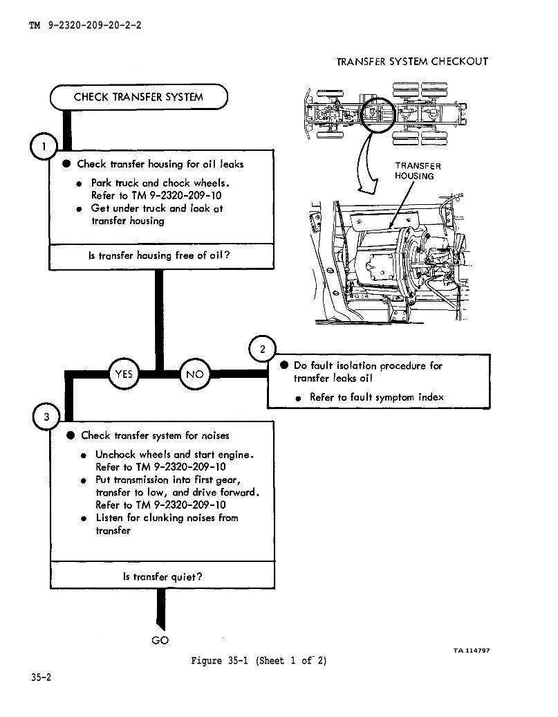
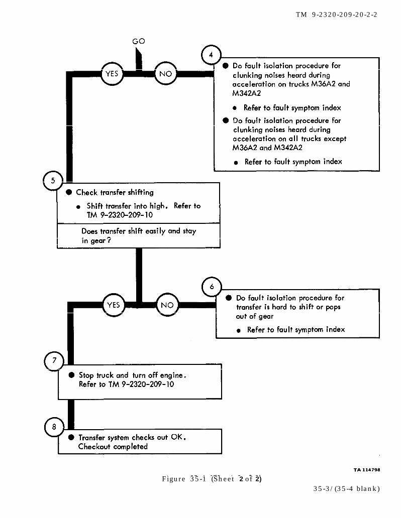
CHAPTER 35
TRANSFER SYSTEM CHECKOUT PROCEDURES
35-1. GENERAL. This chapter gives procedures for checking out the system aftertroubleshooting and repair have been done. Procedures are set up in flow chart formshowing the checkout steps in order and referring to the fault symptom index when thesystem does not check out.
35-1
TM 9-2320-209-10
TM 9-2320-209-10
TM 9-2320-209-10
TM 9-2320-209-20-2-2
Figure 35-1 (Sheet 1 of 2)
35-2
TM 9-2320-209-10
TM 9-2320-209-10
TM 9-2320-209-20-2-2
Figure 35-1 (Sheet 2 of 2)
35-3/(35-4 blank)

TM 9-2320-209-20-2-2
CHAPTER 36
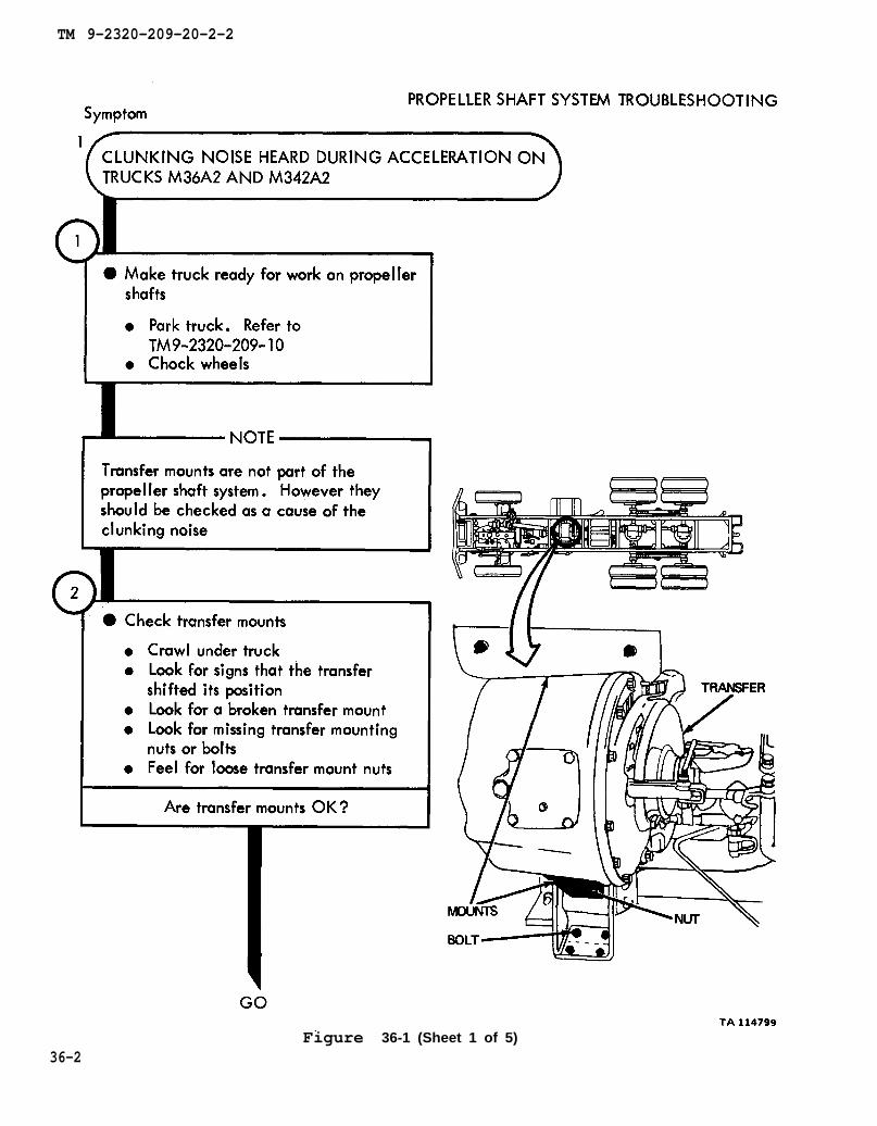
PROPELLER SHAFT SYSTEM TROUBLESHOOTING
36-1. EQUIPMENT ITEMS COVERED. This chapter gives equipment troubleshootingprocedures for the propeller shaft system, for which there are authorized correctivemaintenance tasks at the organizational maintenance level.
36-2. EQUIPMENT ITEMS NOT COVERED. All equipment items for which correctivemaintenance is authorized at the organizational maintenance level are covered in thischapter.
36-1
TM 9-2320-209-10
TM 9-2320-209-20-2-2
Figure 36-1 (Sheet 1 of 5)36-2

TM 9-2320-209-20-2-2
Figure 36-1 (Sheet 2 of 5)36-3
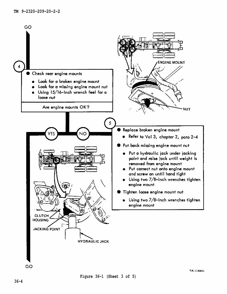
chapter 2 para 2-4
TM 9-2320-209-20-2-2
36-4Figure 36-1 (Sheet 3 of 5)
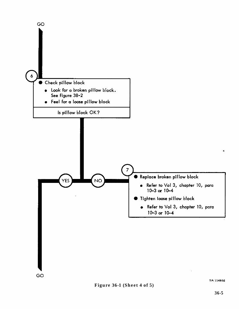
chapter 10 para 10-3
para 10-3 chapter 10
figure 38-2
Figure 36-1 (Sheet 4 of 5)
36-5

figure 38-2
chapter 10 para 10-3
chapter 10 para 10-3
chapter 10 para 10-3
TM 9-2320-209-20-2-2
36-6Figure 36-1 (Sheet 5 of 5)
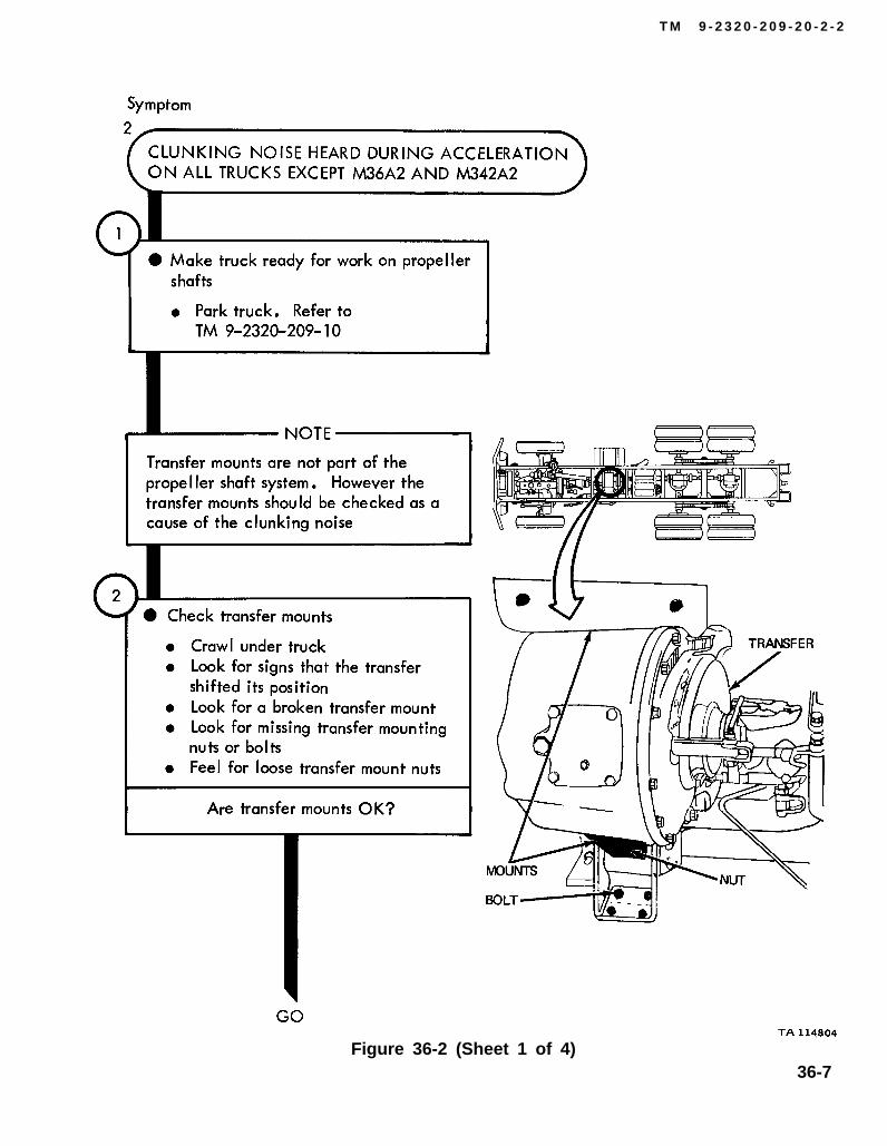
TM 9-2320-209-10
T M 9 - 2 3 2 0 - 2 0 9 - 2 0 - 2 - 2
Figure 36-2 (Sheet 1 of 4)36-7
TM 9-2320-209-20-2-2
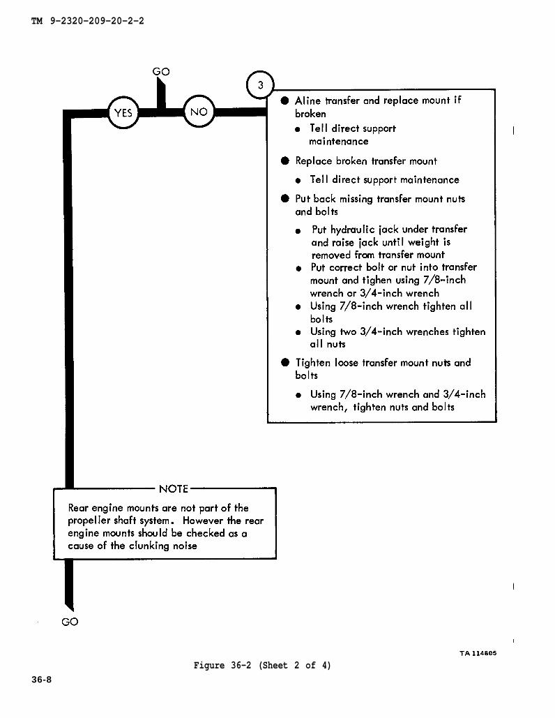
Figure 36-2 (Sheet 2 of 4)36-8
chapter 2 para 2-4
TM 9-2320-209-20-2-2
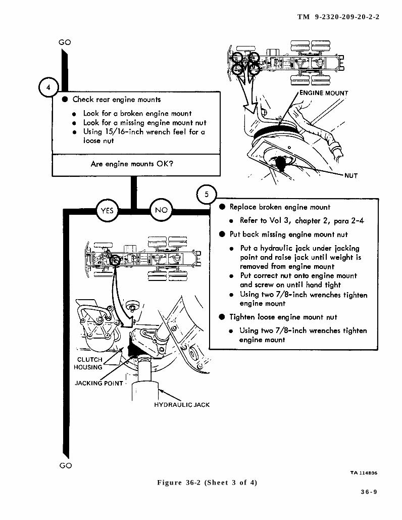
Figure 36-2 (Sheet 3 of 4)3 6 - 9
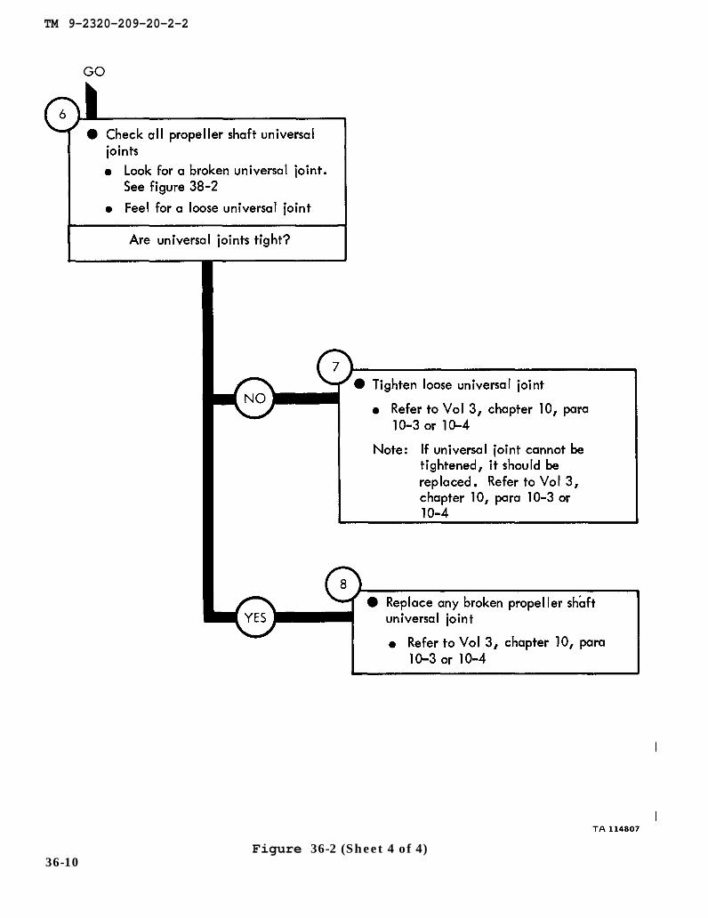
figure 38-2
chapter 10 para 10-3
chapter 10 para 10-3
chapter 10 para 10-3
TM 9-2320-209-20-2-2
Figure 36-2 (Sheet 4 of 4)36-10

TM 9-2320-209-20-2-2
CHAPTER 37
PROPELLER SHAFT SYSTEM TROUBLESHOOTING SUMMARY
37-1. GENERAL. This chapter gives a summary of troubleshooting procedures givenin chapter 36 for the propeller shaft system.
37-2. PROCEDURES. The summary in this chapter covers all fault symptoms foundin the detailed troubleshooting procedures. Chapter 7 outlines a sample troubleshoot-ing procedure. The summary procedures are based on the “what-to-do” portions ofthe detailed procedures and do not include the “how-to-do-it” instructions. Warn-ings, cautions, and notes are given where needed.
37-1

TM 9-2320-209-20-2-2
PROPELLER SHAFT SYSTEM TROUBLESHOOTING SUMMARY
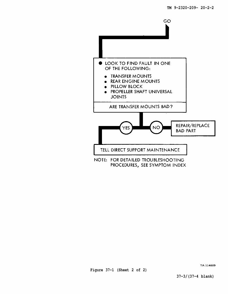
Figure 37-1 (Sheet 1 of 2)37-2
TM 9-2320-209- 20-2-2
Figure 37-1 (Sheet 2 of 2)
37-3/(37-4 blank)


TM 9-2320-209-20-2-2
CHAPTER 38
PROPELLER SHAFT SYSTEM SUPPORT DIAGRAMS
38-1. GENERAL. This chapter gives the diagrams you need when doing trouble-shooting procedures in chapter 36. Table 3-1 is a complete listing of all supportdiagrams used in this manual.
38-1

TM 9-2320-209-20-2-2
Figure 38-1. Propeller Shaft System Support Diagram
38-2

TM 9-2320-209-20-2-2
Figure 38-2. Propeller Shaft System Support Diagram
38-3/(38-4 blank)


TM 9-2320-209-20-2-2
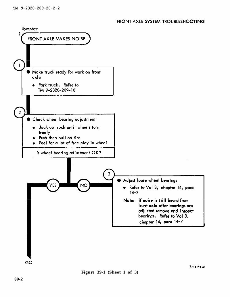
CHAPTER 39
FRONT AXLE SYSTEM TROUBLESHOOTING
39-1. EQUIPMENT ITEMS COVERED. This chapter gives equipment troubleshootingprocedures for the front axle system, for which there are authorized correctivemaintenance tasks at the organizational maintenance level.
39-2. EQUIPMENT ITEMS NOT COVERED. All equipment items for which correctivemaintenance is authorized at the organizational maintenance level are covered in thischapter.
39-1
TM 9-2320-209-10
chapter 14 para 14-7
chapter 14 para 14-7
TM 9-2320-209-20-2-2
39-2
Figure 39-1 (Sheet 1 of 3)
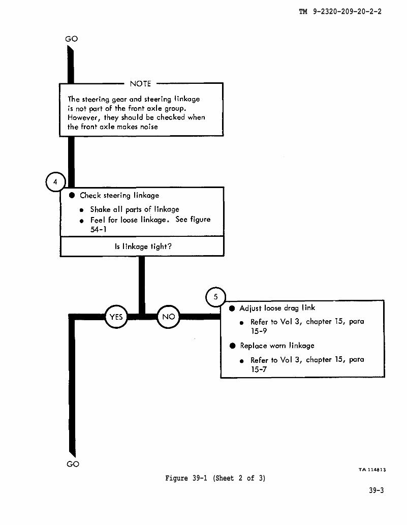
figure 54-1
chapter 15 para 15-9
chapter 15 para 15-7
TM 9-2320-209-20-2-2
Figure 39-1 (Sheet 2 of 3)
39-3
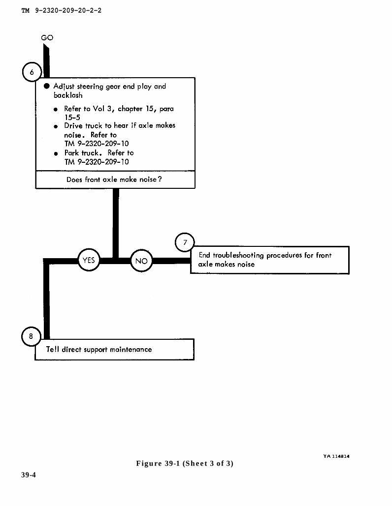
chapter 15 para 15-5
TM 9-2320-209-10
TM 9-2320-209-10
TM 9-2320-209-20-2-2
Figure 39-1 (Sheet 3 of 3)39-4

TM 9-2320-209-10
figure 54-1
TM 9-2320-209-20-2-2
Figure 39-2 (Sheet 1 of 4)39-5
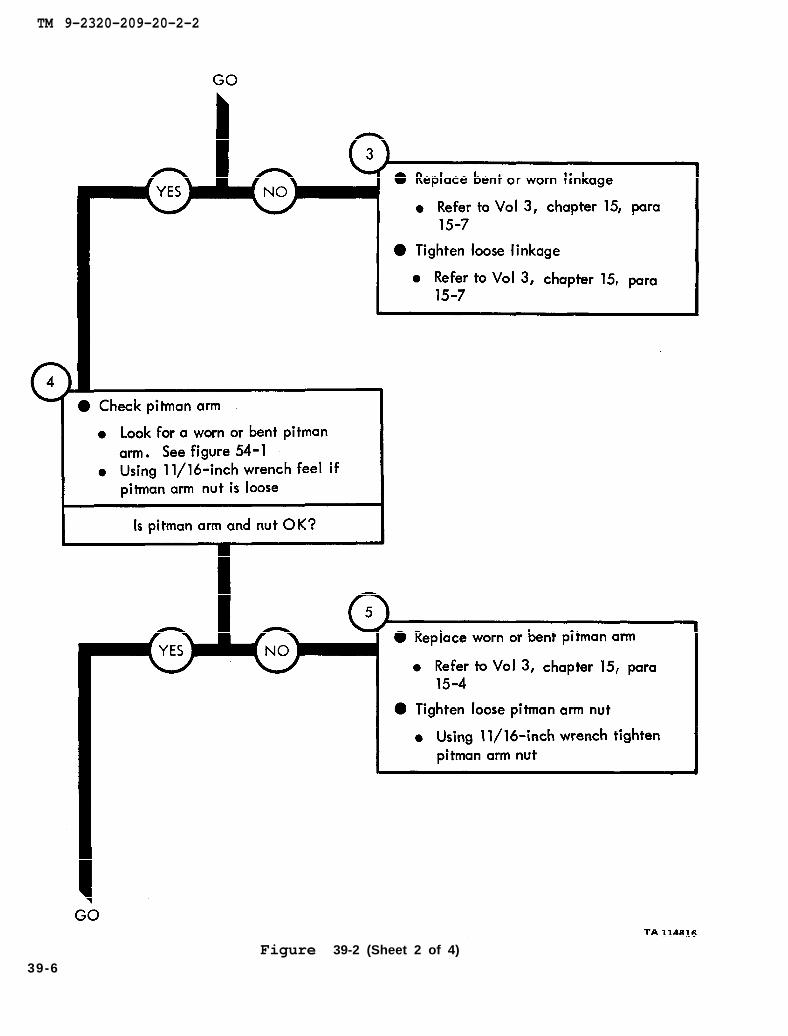
chapter 15 para 15-7
chapter 15 para 15-7
figure 54-1
chapter 15 para 15-7
TM 9-2320-209-20-2-2
39-6Figure 39-2 (Sheet 2 of 4)
figure 54-1
chapter 15 para 15-9
chapter 15 para 15-7
TM 9-2320-209-20-2-2
Figure 39-2 (Sheet 3 of 4)
39-7

chapter 14 para 14-7
chapter 15 para 15-3
chapter 15
chapter 15
para 15-3
para 15-5
TM 9-2320-209-20-2-2
Figure 38-2 (Sheet 4 of 4)39-8
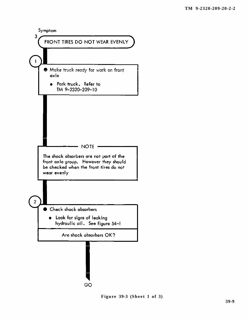
TM 9-2320-209-10
figure 54-1
Figure 39-3 (Sheet 1 of 3)
TM 9-2320-209-20-2-2
39-9
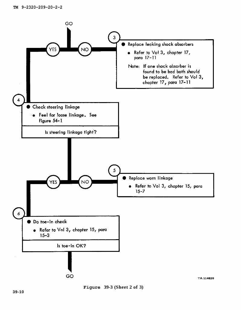
chapter 17
para 17-11
chapter 17 para 17-11
figure 54-1
chapter 15 para 15-7
chapter 15 para 15-3
TM 9-2320-209-20-2-2
Figure 39-3 (Sheet 2 of 3)39-10

chapter 15 para 15-3
chapter 14 para 14-7
TM 9-2320-209-20-2-2
Figure 39-3 (Sheet 3 of 3)39-11/(39-12 blank)


TM 9-2320-209-20-2-2
CHAPTER 40
FRONT AXLE SYSTEM TROUBLESHOOTING SUMMARY
40-1. GENERAL. This chapter gives a summary of troubleshooting procedures givenin chapter 39 for the front axle system.
40-2. PROCEDURES. The summary in this chapter covers all fault symptoms foundin the detailed troubleshooting procedures. Chapter 7 outlines a sample troubleshoot-ing procedure. The summary procedures are based on the “what-to-do” portions ofthe detailed procedures and do not include the “how-to-do-it” instructions. Warn-ings, cautions, and notes are given where needed.
40-1

TM 9-2320-209-20-2-2
FRONT AXLE SYSTEM TROUBLESHOOTING SUMMARY
40-2Figure 40-1 (Sheet 1 of 3)
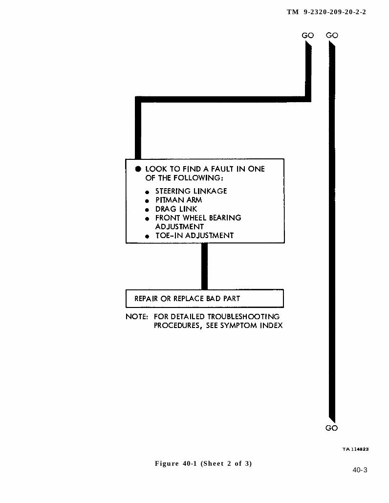
TM 9-2320-209-20-2-2
Figure 40-1 (Sheet 2 of 3)40-3

TM 9-2320-209-20-2-2
40-4Figure 40-1 (Sheet 3 of 3)
TM 9-2320-209-20-2-2
CHAPTER 41
FRONT AXLE SYSTEM CHECKOUT PROCEDURES
41-1. GENERAL. This chapter gives procedures for checking out the system aftertroubleshooting and repair have been done. Procedures are set up in flow chart formshowing the checkout steps in order and referring to the fault symptom index whenthe system does not check out.
41-1

TM 9-2320-209-10
TM 9-2320-209-10
TM 9-2320-209-20-2-2
41-2Figure 41-1 (Sheet 1 of 2)

TM 9-2320-209-10
TM 9-2320-209-20-2-2
Figure 41-1 (Sheet 2 of 2)41-3/ (41-4 blank)


TM 9-2320-209-20-2-2
CHAPTER 42
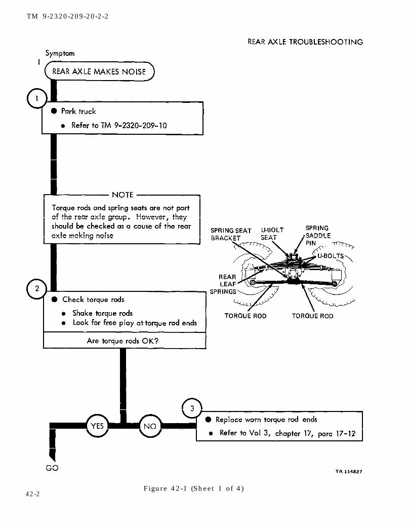
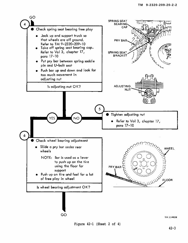
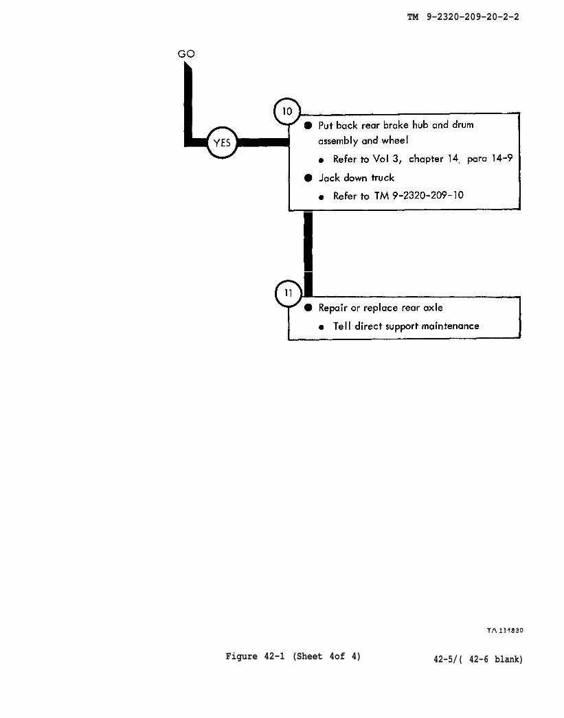
REAR AXLE SYSTEM TROUBLESHOOTING
42-1. EQUIPMENT ITEMS COVERED. This chapter gives equipment troubleshootingprocedures for the rear axle system, for which there are authorized corrective mainte-nance tasks at the organizational maintenance level.
42-2. EQUIPMENT ITEMS NOT COVERED. All equipment items for which correctivemaintenance is authorized at the organizational maintenance level are covered in thischapter.
42-1
TM 9-2320-209-10
chapter 17 para 17-12
TM 9-2320-209-20-2-2
Figure 42-1 (Sheet 1 of 4)42-2
TM 9-2320-209-10
chapter 17
para 17-10
chapter 17
para 17-10
TM 9-2320-209-20-2-2
Figure 42-1 (Sheet 2 of 4)42-3

chapter 14 para 14-10
chapter 14
para 14-9
chapter 14 para 14-9
chapter 14 para 14-10
TM 9-2320-209-20-2-2
42-4Figure 42-1 (Sheet 3 of 4)
chapter 14 para 14-9
TM 9-2320-209-10
TM 9-2320-209-20-2-2
Figure 42-1 (Sheet 4of 4) 42-5/( 42-6 blank)

TM 9-2320-209-20-2-2
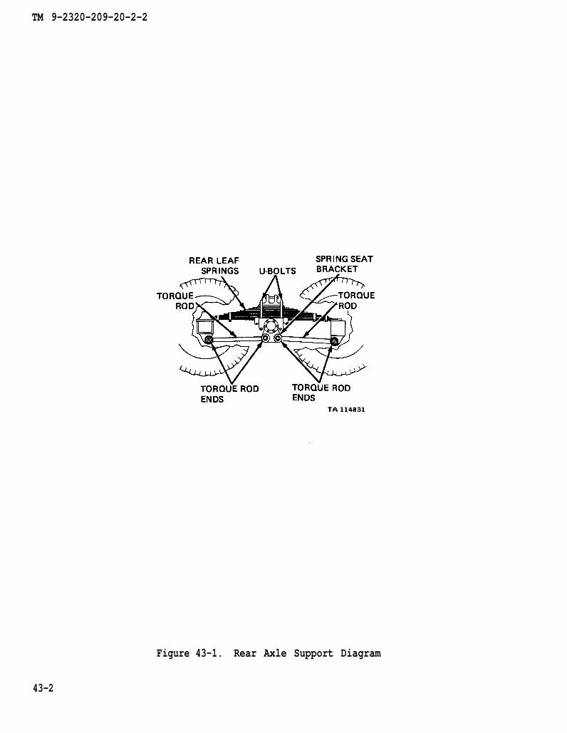
CHAPTER 43
REAR AXLE SYSTEM SUPPORT DIAGRAMS
43-1. GENERAL. This chapter gives the diagrams you need when doing trouble-shooting procedures in chapter 42. Table 3-1 is a complete listing of all supportdiagrams used in this manual.
43-1
TM 9-2320-209-20-2-2
Figure 43-1. Rear Axle Support Diagram
43-2

TM 9-2320-209-20-2-2
CHAPTER 44
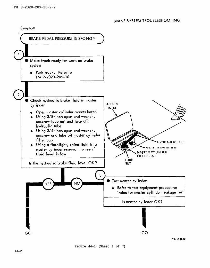
BRAKE SYSTEM TROUBLESHOOTING
44-1. EQUIPMENT ITEMS COVERED. This chapter gives equipment troubleshootingprocedures for the brake system, for which there are authorized corrective mainte-nance tasks at the organizational maintenance level.
44-2. EQUIPMENT ITEMS NOT COVERED. All equipment items for which correctivemaintenance is authorized at the organizational maintenance level are covered in thischapter.
44-1
TM 9-2320-209-10
TM 9-2320-209-20-2-2
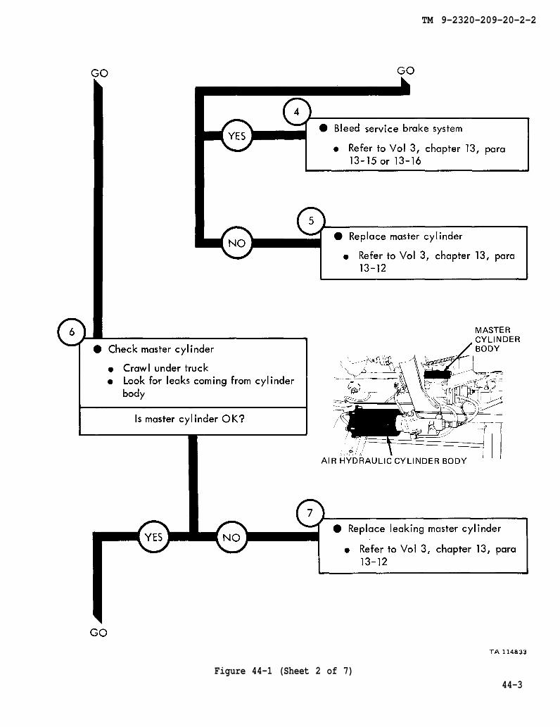
Figure 44-1 (Sheet 1 of 7)44-2
chapter 13 para 13-15
chapter 13 para 13-12
chapter 13 para 13-12
TM 9-2320-209-20-2-2
Figure 44-1 (Sheet 2 of 7)44-3

figure 46-1
chapter 13 para 13-15
chapter 13 para 13-14
TM 9-2320-209-20-2-2
44-4Figure 44-1 (Sheet 3 of 7)

figure 46-1
chapter 13
chapter 13
para 13-15
para 13-13
TM 9-2320-209-20-2-2
Figure 44-1 (Sheet 4 of 7) 4 4 - 5
chapter 13 para 13-21
Chapter 14 para 14-4
TM 9-2320-209-20-2-2
Figure 44-1 (Sheet 5 of 7)44-6
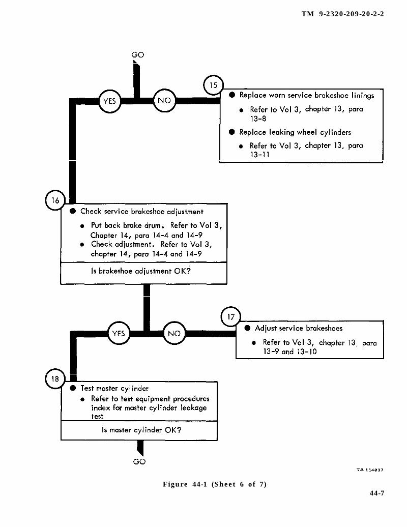
chapter 13 para 13-8
chapter 13 para 13-11
Chapter 14 para 14-4
chapter 14 para 14-4
chapter 13 para 13-9
TM 9-2320-209-20-2-2
Figure 44-1 (Sheet 6 of 7)44-7
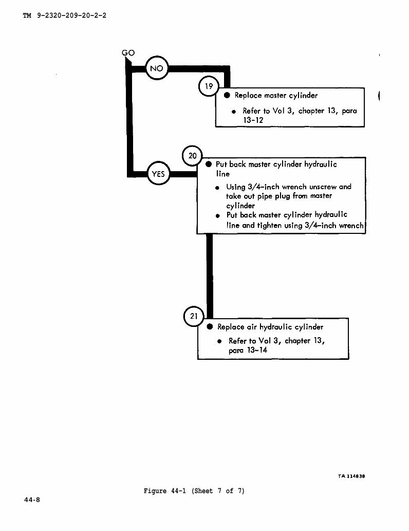
chapter 13 para 13-12
chapter 13
para 13-14
TM 9-2320-209-20-2-2
Figure 44-1 (Sheet 7 of 7)44-8

TM 9-2320-209-10
chapter 13 para 13-12
FIGURE 46-1
TM 9-2320-209-20-2-2
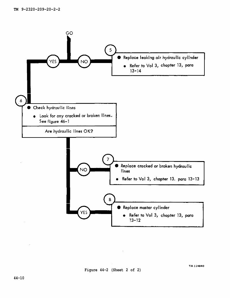
Figure 44-2 (Sheet 1 of 2)44-9
chapter 13 para 13-14
figure 46-1
chapter 13 para 13-13
chapter 13 para 13-12
TM 9-2320-209-20-2-2
Figure 44-2 (Sheet 2 of 2)
44-10
TM 9-2320-209-10
TM 9-2320-209-20-2-2
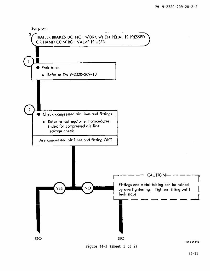
Figure 44-3 (Sheet 1 of 2)
44-11
chapter 13 para 13-21
TM 9-2320-209-20-2-2
Figure 44-3 (Sheet 2 of 2)
44-12

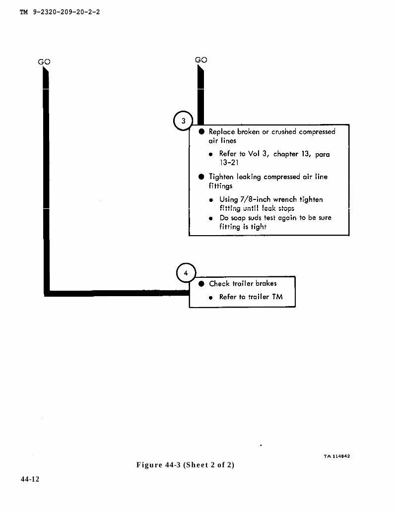
TM 9-2320-209-10
chapter 13 para 13-21
TM 9-2320-209-20-2-2
Figure 44-4 (Sheet 1 of 3)
44-13
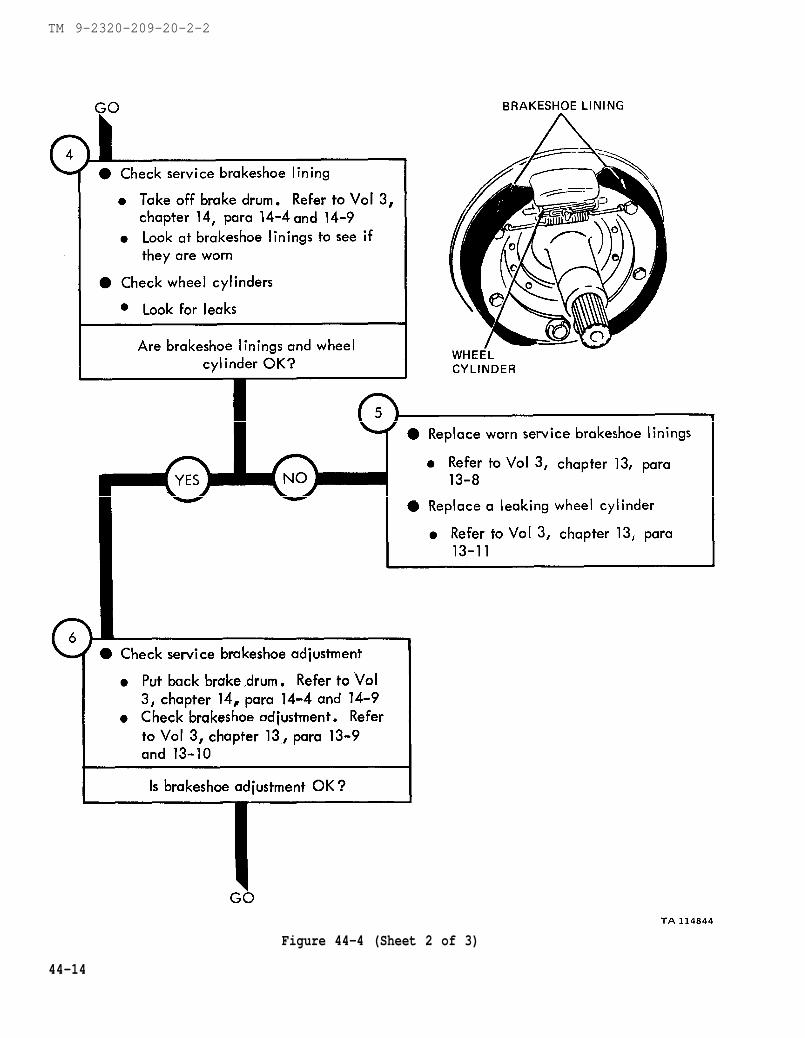
chapter 14 para 14-4
chapter 13 para 13-8
chapter 13 para 13-11
chapter 14 para 14-4
chapter 13 para 13-9
TM 9-2320-209-20-2-2
Figure 44-4 (Sheet 2 of 3)
44-14
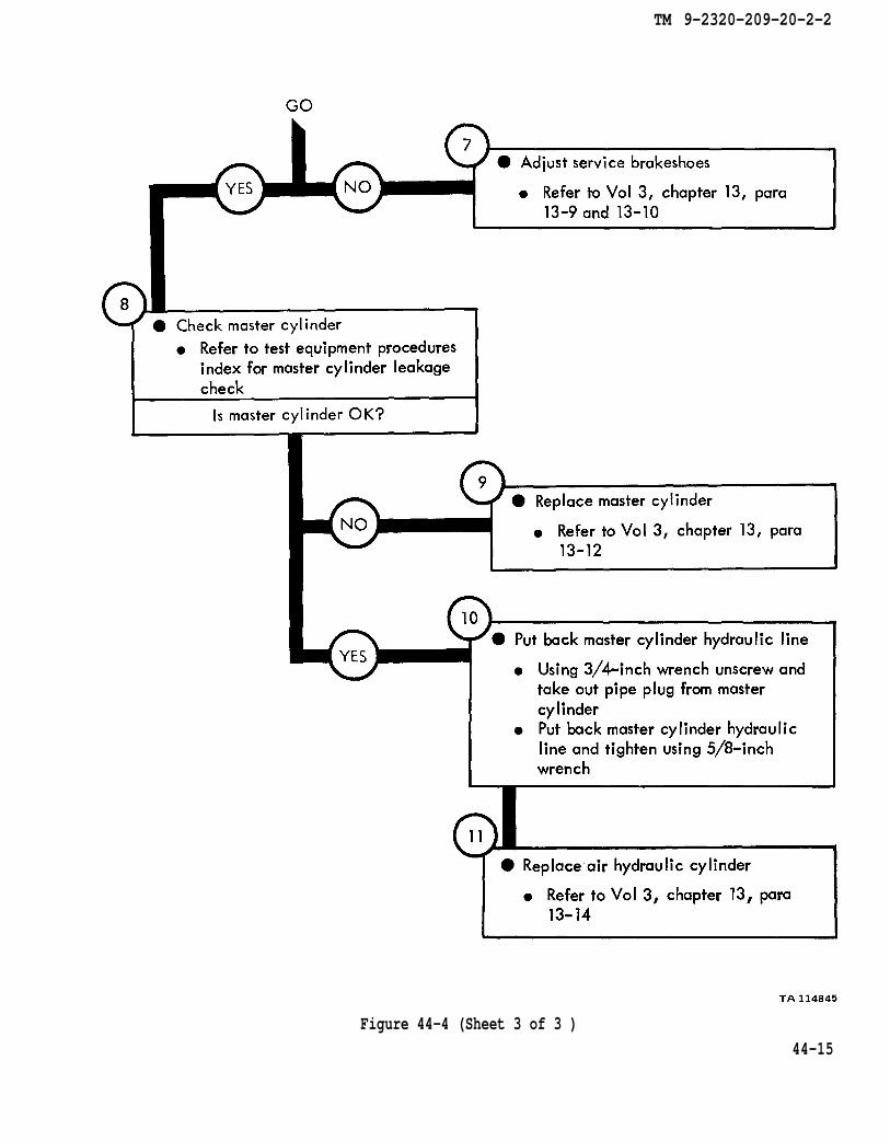
chapter 13 para 13-9
chapter 13 para 13-12
chapter 13 para 13--14
TM 9-2320-209-20-2-2
Figure 44-4 (Sheet 3 of 3 )
44-15

TM 9-2320-209-10
figure 46-1
chapter 13 para 13-13
chapter 13 para 13-9
TM 9-2320-209-20-2-2
Figure 44-5 (Sheet 1 of 3)
44-16

chapter 13 para 13-9
chapter 14 para 14-3
TM 9-2320-209-20-2-2
Figure 44-5 (Sheet 2 of 3)
44-17
chapter 14 para 14-8
chapter 14 para 14-3
chapter 13 para 13-11
chapter 13 para 13-9
TM 9-2320-209-20-2-2
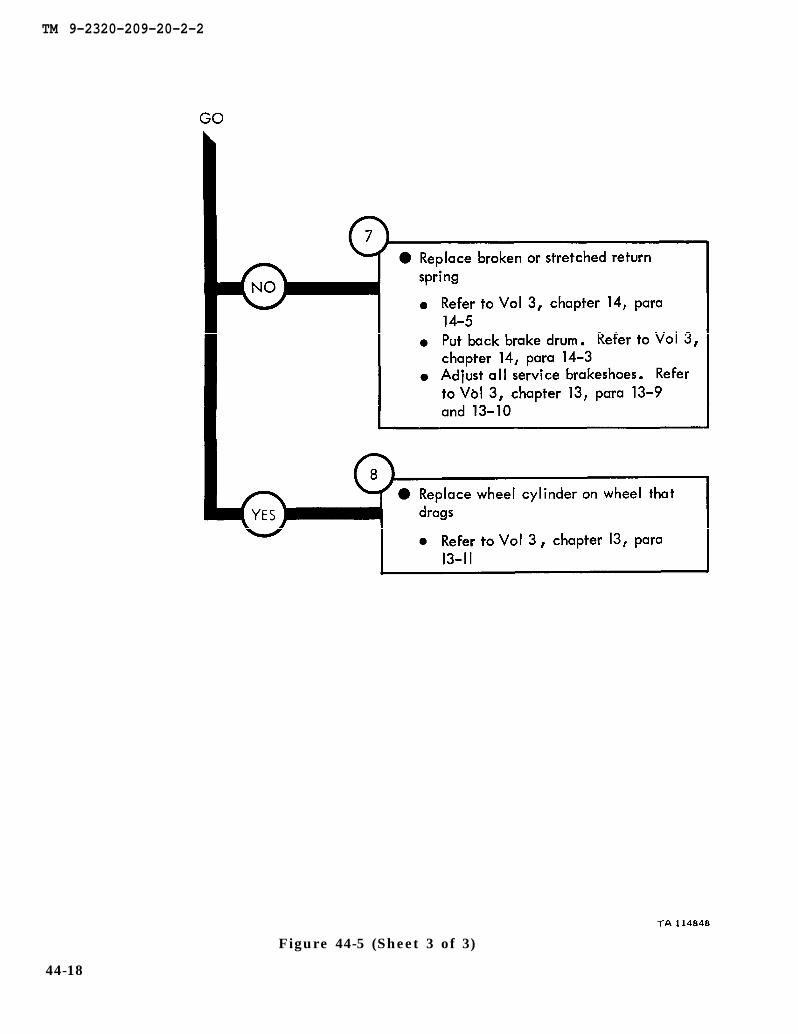
Figure 44-5 (Sheet 3 of 3)
44-18
TM 9-2320-209-10
chapter 13
para 13-19
figure 46-1
TM 9-2320-209-20-2-2
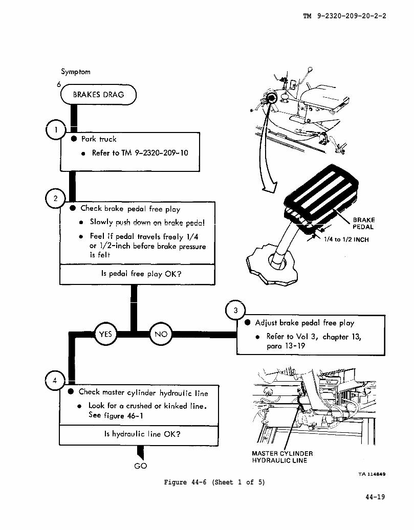
Figure 44-6 (Sheet 1 of 5)
44-19

chapter 13 para 13-13
figure 46-1
chapter 13 para 13-13
chapter 13 para 13-9
TM 9-2320-209-20-2-2
44-20
Figure 44-6 (Sheet 2 of 5)
chapter 13 para 13-9
chapter 13 para 13-12
chapter 13 para 13-14
TM 9-2320-209-20-2-2
Figure 44-6 (Sheet 3 of 5)
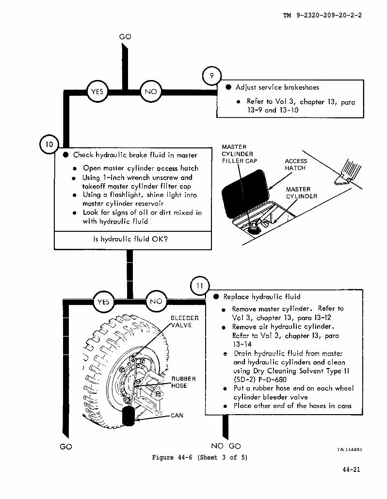
44-21

chapter 13 para 13-12
chapter 13
para 13-14
chapter 2 para 13-15
chapter 13 para 13-12
TM 9-2320-209-20-2-2
TA 114852
Figure 44-6 (Sheet 4 of 5)
44-22
chapter 13 para 13-14
TM 9-2320-209-20-2-2
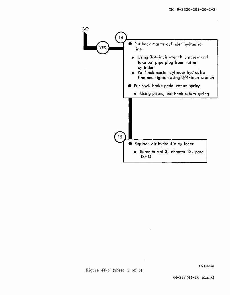
Figure 44-6 (Sheet 5 of 5)
44-23/(44-24 blank)

TM 9-2320-209-20-2-2
CHAPTER 45
BRAKE SYSTEM TROUBLESHOOTING SUMMARY
45-1. GENERAL. This chapter gives a summary of troubleshooting procedures givenin chapter 44 for the brake system.
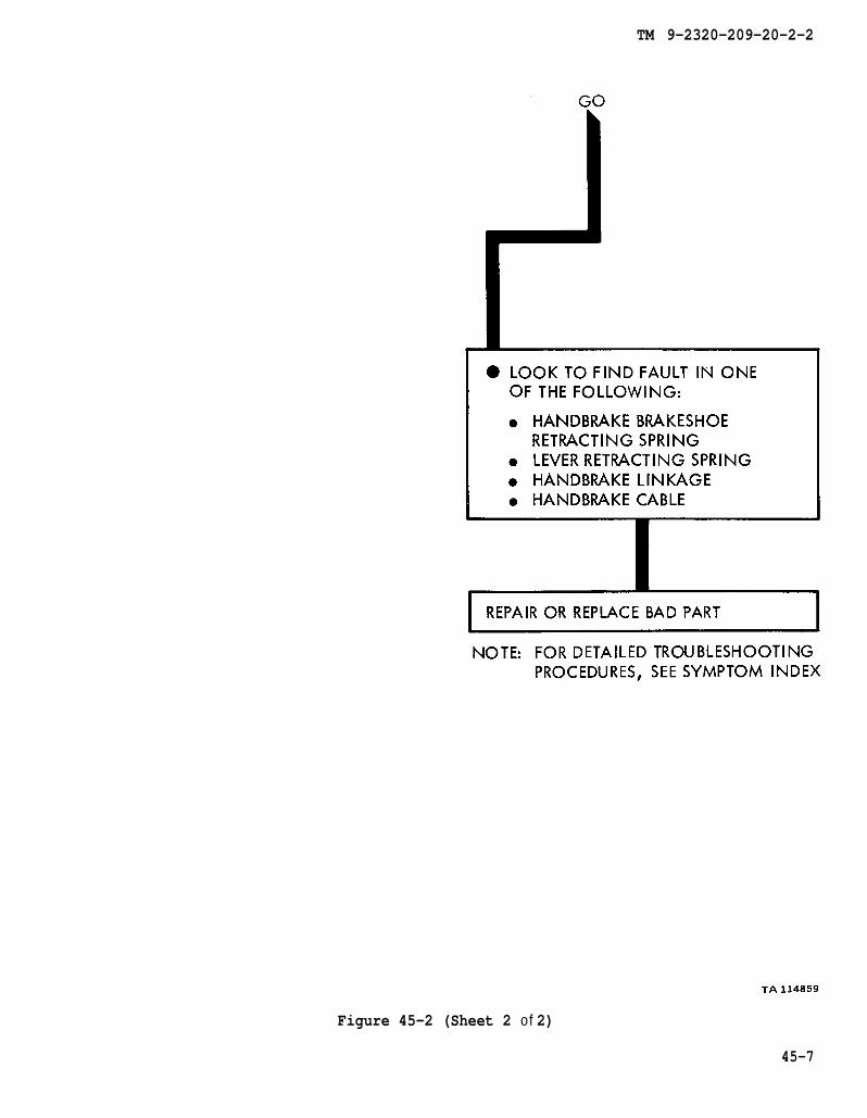
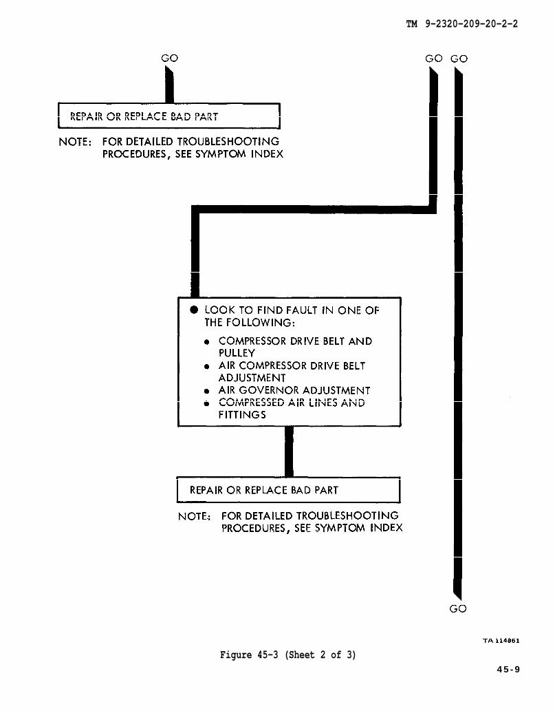
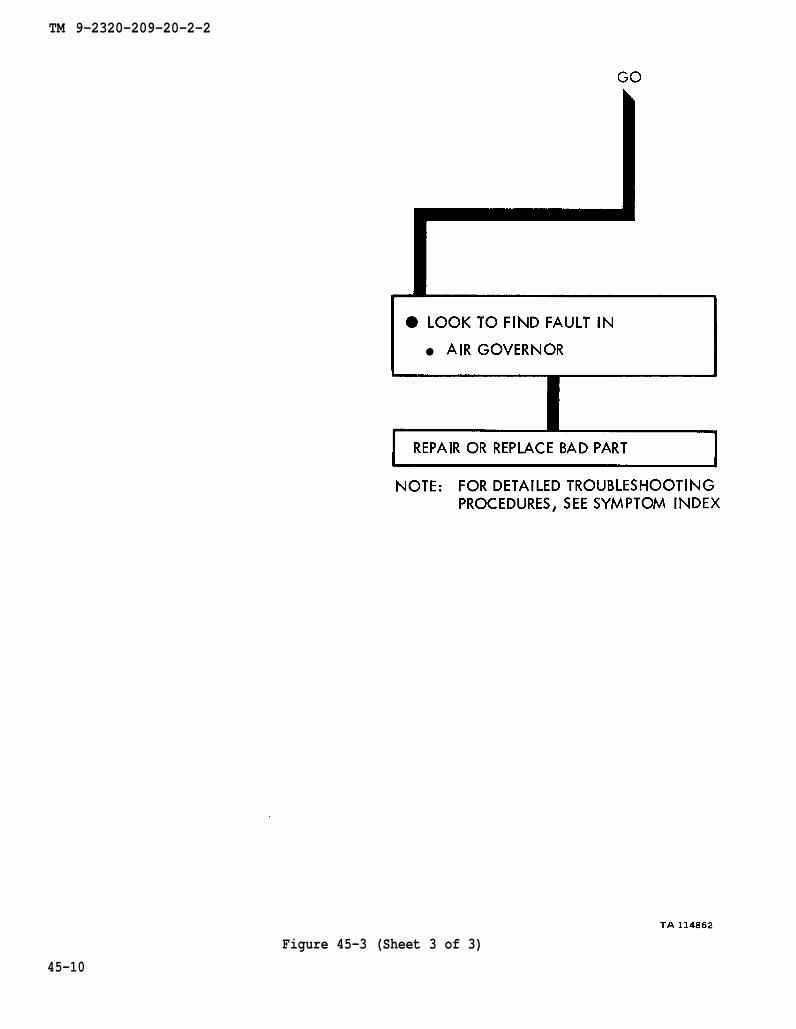
45-2. PROCEDURES. The summary in this chapter covers all fault symptoms foundin the detailed troubleshooting procedures. Chapter 7 outlines a sample troubleshoot-ing procedure. The summary procedures are based on the “what-to-do” portions ofthe detailed procedures and do not include the “how-to-do-it” instructions. Warn-ings, cautions, and notes are given where needed.
45-1
TM 9-2320-209-20-2-2
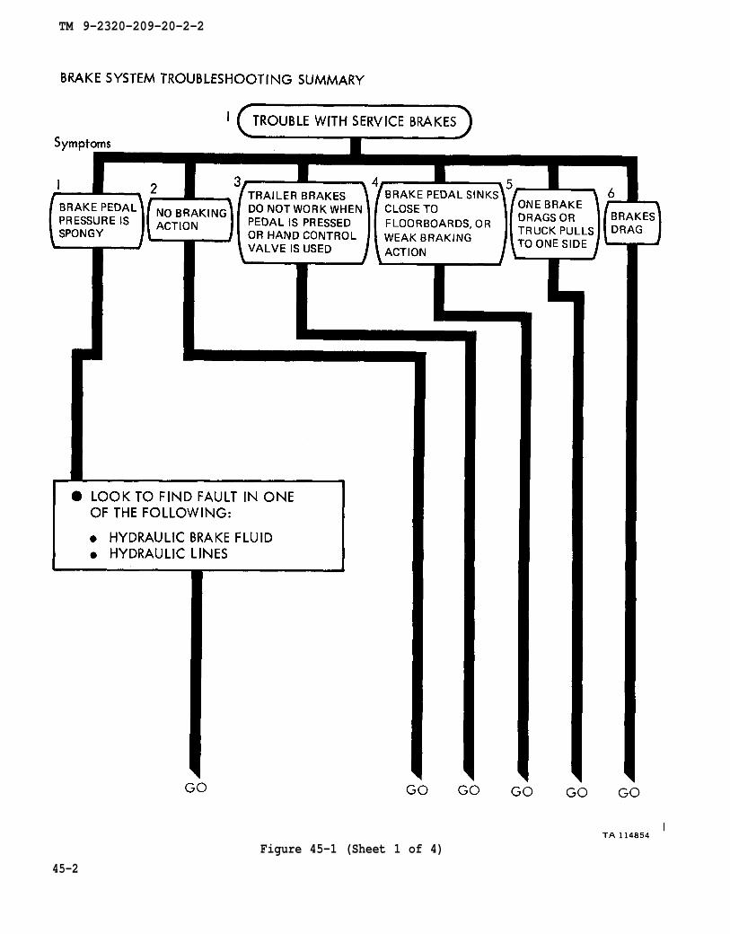
Figure 45-1 (Sheet 1 of 4)
45-2

Figure 45-1 (Sheet 2 of 4)
TM 9-2320-209-20-2-2
45-3
TM 9-2320-209-20-2-2
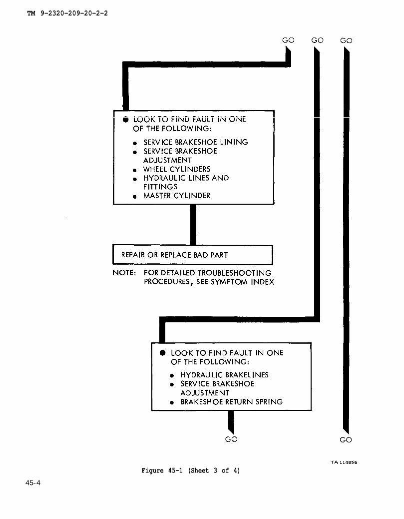
Figure 45-1 (Sheet 3 of 4)
45-4
TM 9-2320-209-20-2-2
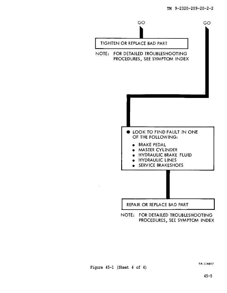
Figure 45-1 (Sheet 4 of 4)
45-5

TM 9-2320-209-20-2-2
Figure 45-2 (Sheet 1 of 2)
45-6
TM 9-2320-209-20-2-2
Figure 45-2 (Sheet 2 of 2)
45-7

TM 9-2320-209-20-2-2
Figre 45-3 (Sheet 1 of 3)
45-8
TM 9-2320-209-20-2-2
Figure 45-3 (Sheet 2 of 3)4 5 - 9
TM 9-2320-209-20-2-2
Figure 45-3 (Sheet 3 of 3)
45-10

TM 9-2320-209-20-2-2
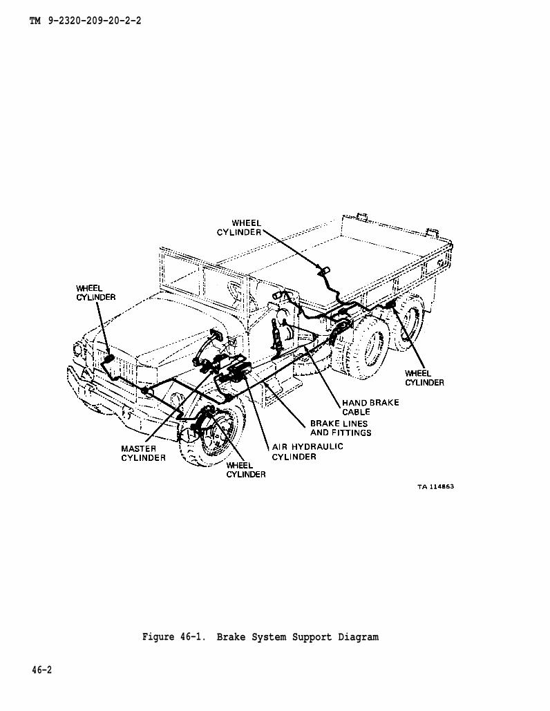
CHAPTER 46
BRAKE SYSTEM SUPPORT DIAGRAMS
46-1. GENERAL. This chapter gives the diagrams you need when doing trouble-shooting procedures in chapter 44. Table 3-1 is a complete listing of all supportdiagrams used in this manual.
46-1
TM 9-2320-209-20-2-2
Figure 46-1. Brake System Support Diagram
46-2
TM 9-2320-209-20-2-2
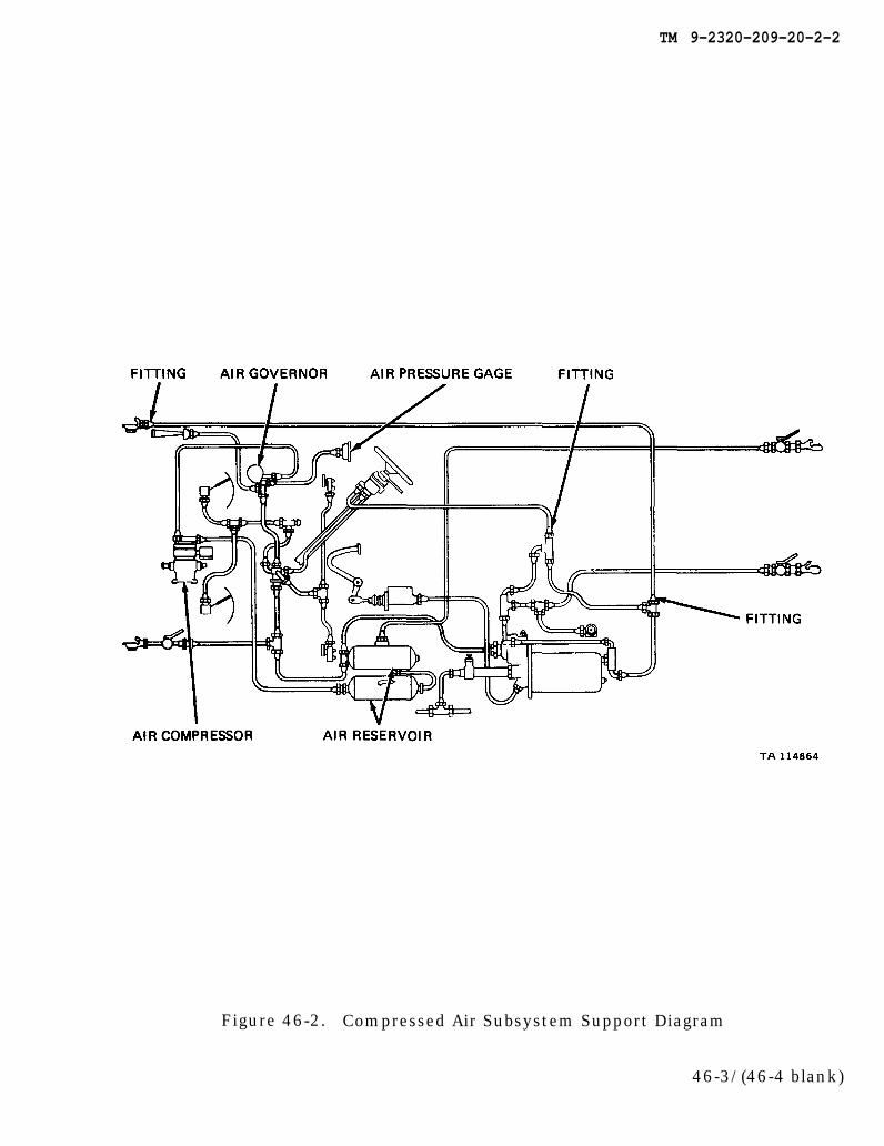
Figure 46-2. Compressed Air Subsystem Support Diagram
46-3/(46-4 blank)


TM 9-2320-209-20-2-2
CHAPTER 47
HANDBRAKE SUBSYSTEM TROUBLESHOOTING
47-1. EQUIPMENT ITEMS COVERED. This chapter gives equipment troubleshootingprocedures for the handbrake subsystem, for which there are authorized correctivemaintenance tasks at the organizational maintenance level.
47-2. EQUIPMENT ITEMS NOT COVERED. All equipment items for which correctivemaintenance is authorized at the organizational maintenance level are covered in thischapter.
47-1

TM 9-2320-209-10
figure 46-1
chapter 13 para 13-7
chapter 13 para 13-5
TM 9-2320-209-20-2-2
47-2
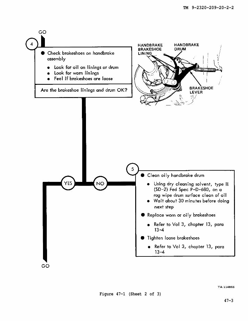
Figure 47-1 (Sheet l of 3)
chapter 13 para 13-4
chapter 13 para 13-4
TM 9-2320-209-20-2-2
Figure 47-1 (Sheet 2 of 3)
47-3
chapter 13 para 13-4
chapter 13 para 13-7
TM 9-2320-209-20-2-2
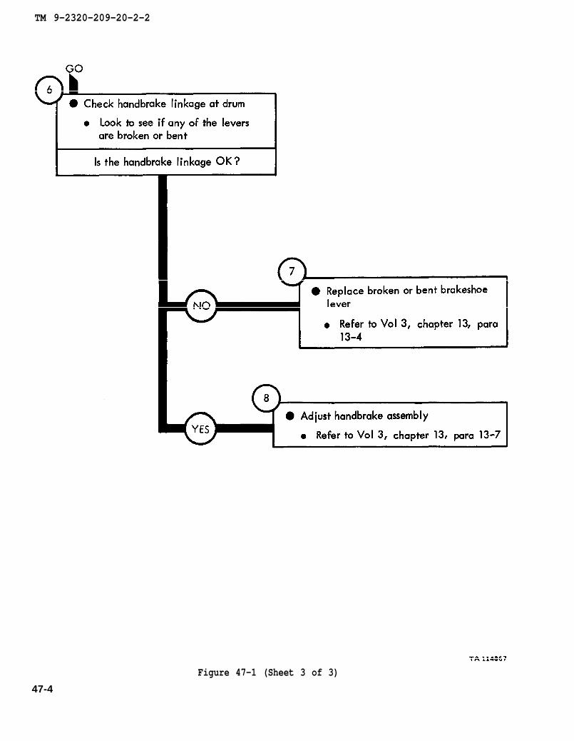
Figure 47-1 (Sheet 3 of 3)
47-4
TM 9-2320-209-10
chapter 13
para 13-4
chapter 13 para 13-4
TM 9-2320-209-20-2-2
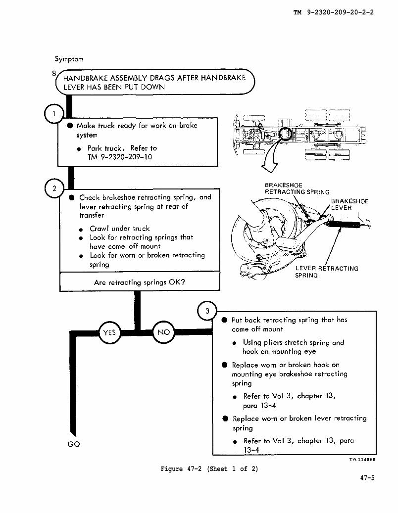
Figure 47-2 (Sheet 1 of 2)47-5

LO 9-2320-209-12/1 figure 46-1
chapter 13 para 13-5
chapter 13 para 13-7
TM 9-2320-209-20-2-2
Figure 47-2 (Sheet 2 of 2)
47-6
TM 9-2320-209-20-2-2
CHAPTER 48
COMPRESSED AIR SUBSYSTEM TROUBLESHOOTING
48-1. EQUIPMENT ITEMS COVERED. This chapter gives equipment troubleshootingprocedures for the compressed air subsystem, for which there are authorized correc-tive maintenance tasks at the organizational maintenance level.
48-2. EQUIPMENT ITEMS NOT COVERED. All equipment items for which correctivemaintenance is authorized at the organizational maintenance level are covered in thischapter.
48-1

TM 9-2320-209-10
chapter 7 para 7-58
chapter 13 para 13-34
chapter 13 para 13-34
chapter 13 para 13-34
TM 9-2320-209-20-2-2
48-2Figure 48-1 (Sheet 1 of 3)

chapter 7 para 7-58
chapter 13 para 13-21
TM 9-2320-209-20-2-2
Figure 48-1 (Sheet 2 of 3)
48-3

TM 9-2320-260-10
chapter 13 para 13-36
chapter 13 para 13-35
chapter 13
para 13-31
TM 9-2320-209-20-2-2
Figure 48-1 (Sheet 3 of 3)48-4

TM 9-2320-209-10
figure 49-1
TM 9-2320-209-20-2-2
Figure 48-2 (Sheet 1 of 2)
48-5
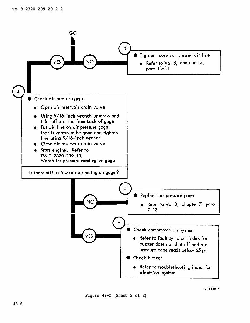
chapter 13
para 13-31
TM 9-2320-209-10.
chapter 7 para 7-13
TM 9-2320-209-20-2-2
Figure 48-2 (Sheet 2 of 2)
48-6

chapter 13 para 13-36
chapter 13
para 13-31
TM 9-2320-209-10
TM 9-2320-209-10
chapter 13
para 13-35
TM 9-2320-209-20-2-2
Figure 48-348-7/(48-8 blank)

TM 9-2320-209-20-2-2
CHAPTER 49
BRAKE SYSTEM TEST PROCEDURES
49-1. GENERAL. This chapter gives test procedures for the tests given inchapter 44, for the brake system.
49-2. TEST SET-UP. Instructions for setup of test equipment and parts to betested are given before the test procedures. Illustrations are used, when needed, toshow you how to hook up the test equipment to the part to be tested.
49-3. TEST PROCEDURE. Detailed step-by-step instructions, in flow chart form,are given for each test. The procedure calls out the type of test and the conditionof the truck system for each part of testing. The step-by-step test will lead you tothe bad component or to a fault symptom within a related system. Reference is madeto the fault symptom index, chapter 6, if the test shows a fault in another system.
49-1
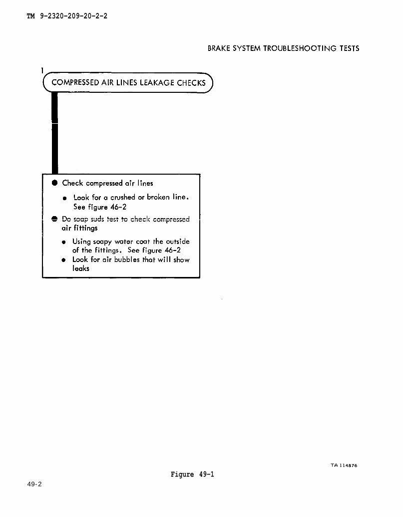
figure 46-2
figure 46-2
TM 9-2320-209-20-2-2
49-2Figure 49-1
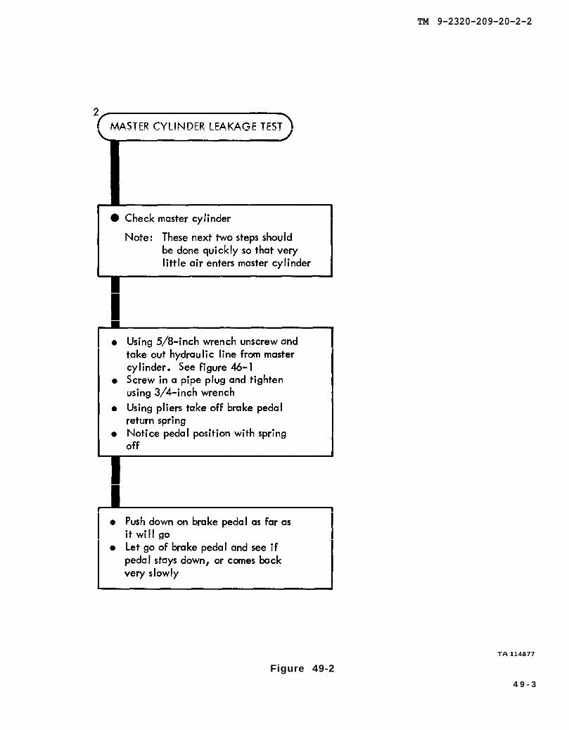
figure 46-1
TM 9-2320-209-20-2-2
Figure 49-2
4 9 - 3

tTM 9-2320-209-10
TM 9-2320-209-20-2-2
Figure 49-349-4
TM 9-2320-209-20-2-2
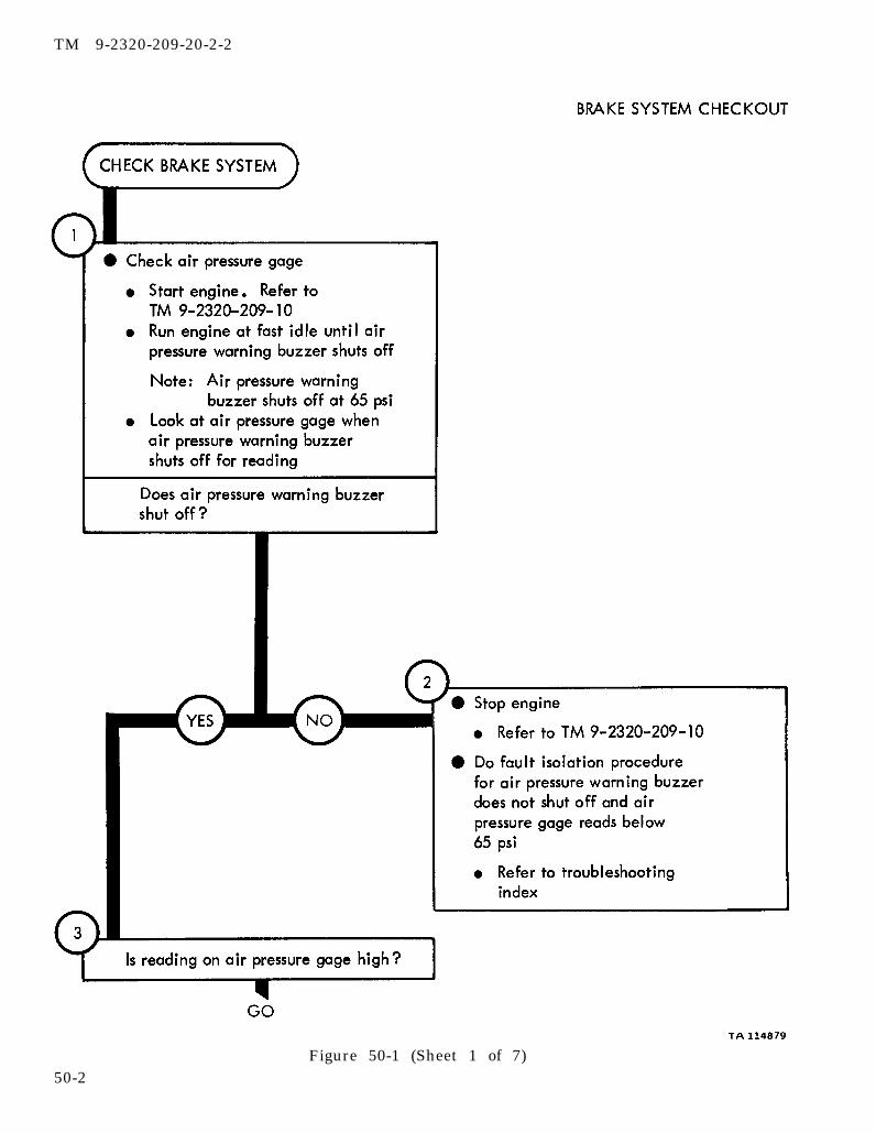
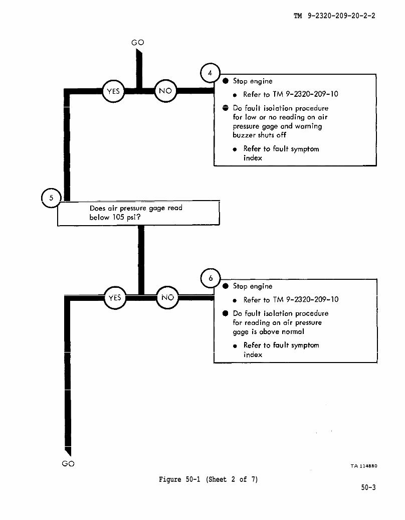
CHAPTER 50
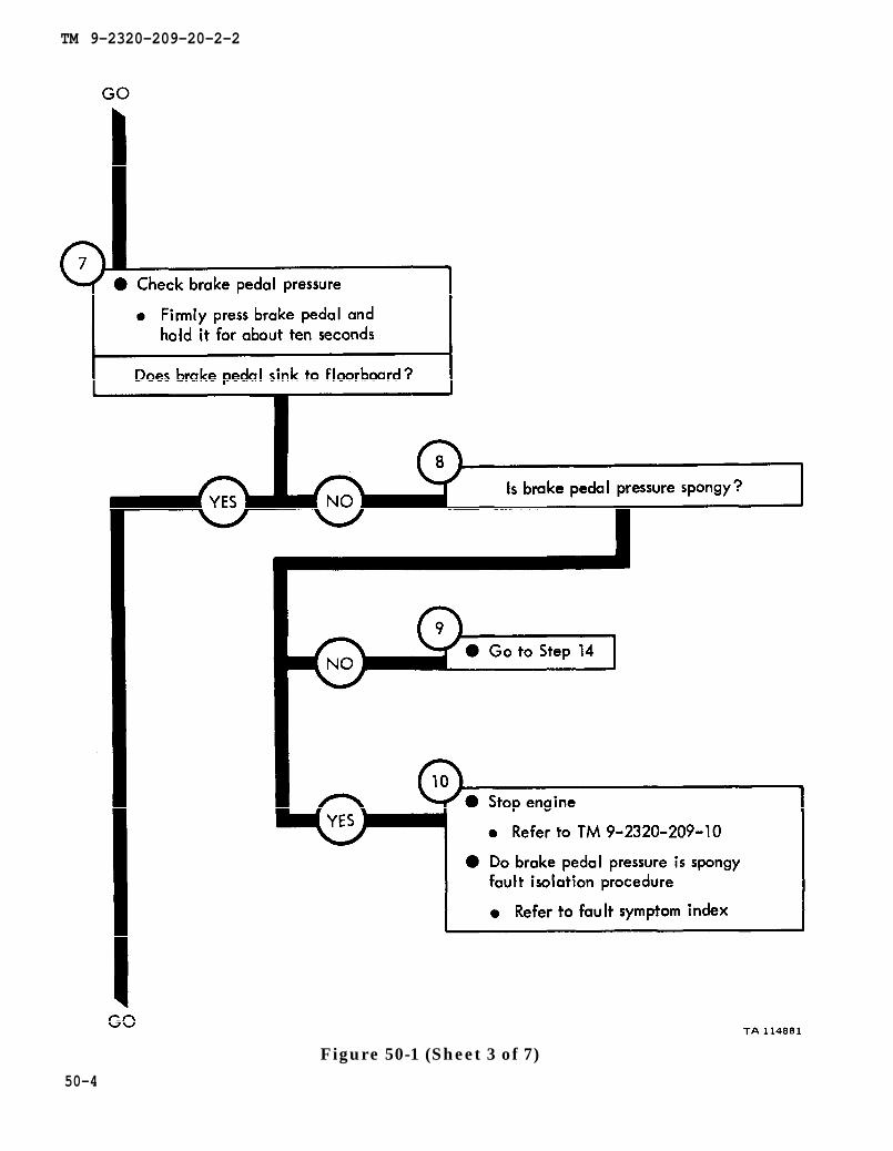
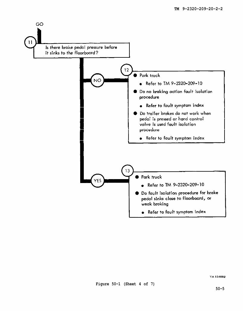
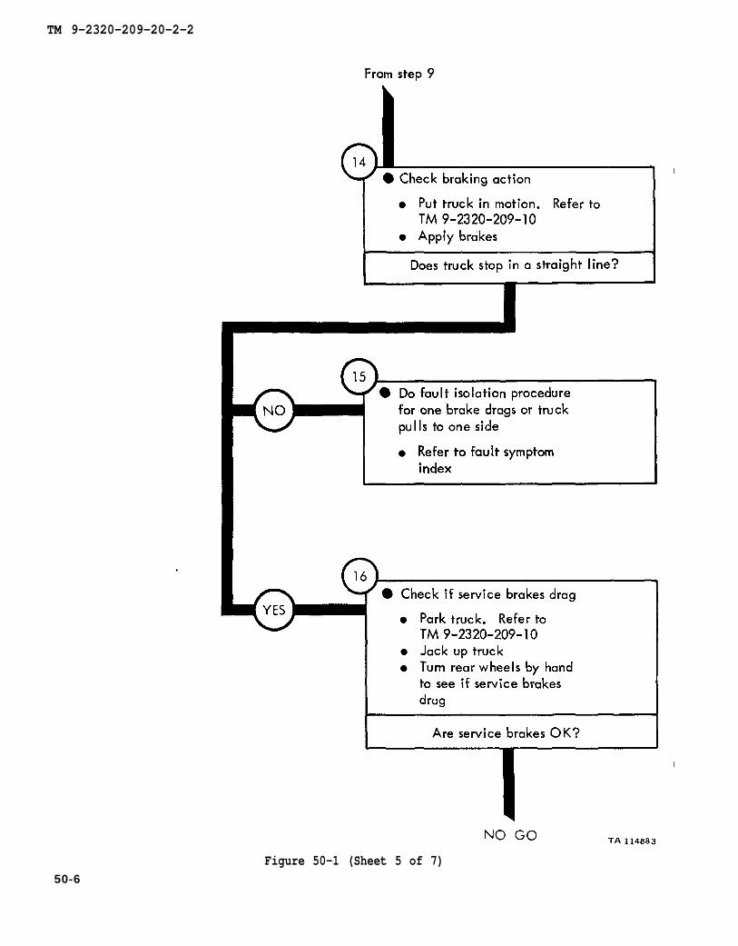
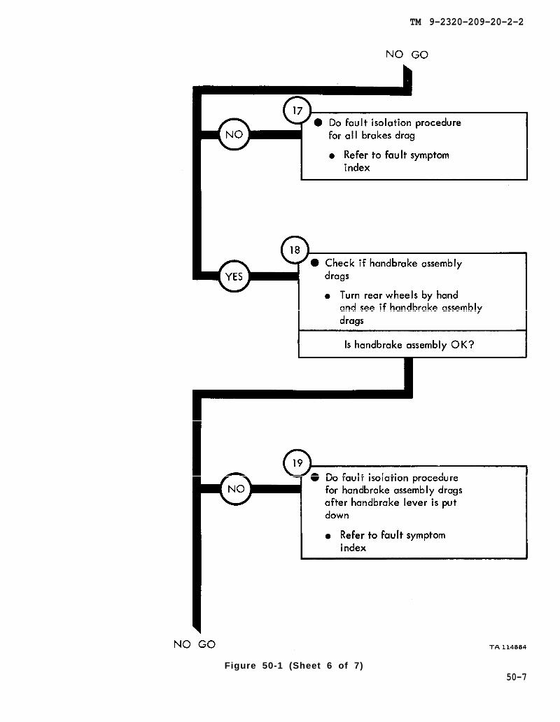
BRAKE SYSTEM CHECKOUT PROCEDURES
50-1. GENERAL. This chapter gives procedures for checking out the system aftertroubleshooting and repair have been done. Procedures are set up in flow chart formshowing the checkout steps in order and referring to the fault symptom index when thesystem does not check out.
50-1
TM 9-2320-209-10
TM 9-2320-209-10
TM 9-2320-209-20-2-2
Figure 50-1 (Sheet 1 of 7)50-2
TM 9-2320-209-10
TM 9-2320-209-10
TM 9-2320-209-20-2-2
Figure 50-1 (Sheet 2 of 7)50-3
TM 9-2320-209-10
TM 9-2320-209-20-2-2
50-4
Figure 50-1 (Sheet 3 of 7)
TM 9-2320-209-10
TM 9-2320-209-10
TM 9-2320-209-20-2-2
Figure 50-1 (Sheet 4 of 7)50-5
TM 9-2320-209-10
TM 9-2320-209-10
TM 9-2320-209-20-2-2
Figure 50-1 (Sheet 5 of 7)50-6
TM 9-2320-209-20-2-2
Figure 50-1 (Sheet 6 of 7)50-7

TM 9-2320-209-10.
TM 9-2320-209-10
TM 9-2320-209-10
TM 9-2320-209-20-2-2
Figure 50-1 (Sheet 7 of 7)
50-8
TM 9-2320-209-20-2-2
CHAPTER 51
WHEEL SYSTEM TROUBLESHOOTING
51-1. EQUIPMENT ITEMS COVERED. This chapter gives equipment troubleshootingprocedures for the wheel system, for which there are authorized corrective mainte-nance tasks at the organizational maintenance level.
51-2. EQUIPMENT ITEMS NOT COVERED. All equipment items for which correctivemaintenance is authorized at the organizational maintenance level are covered in thischapter.
51-1

chapter 11, para 11-3
chapter 14 para 14-3
TM 9-2320-209-20-2-2
51-2Figure 51-1 (Sheet 1 of 2)

chapter 14para 14-6
chapter 14 para 14-12
TM 9-2320-209-20-2-2
Figure 51-1 (Sheet 2 of 2)51-3
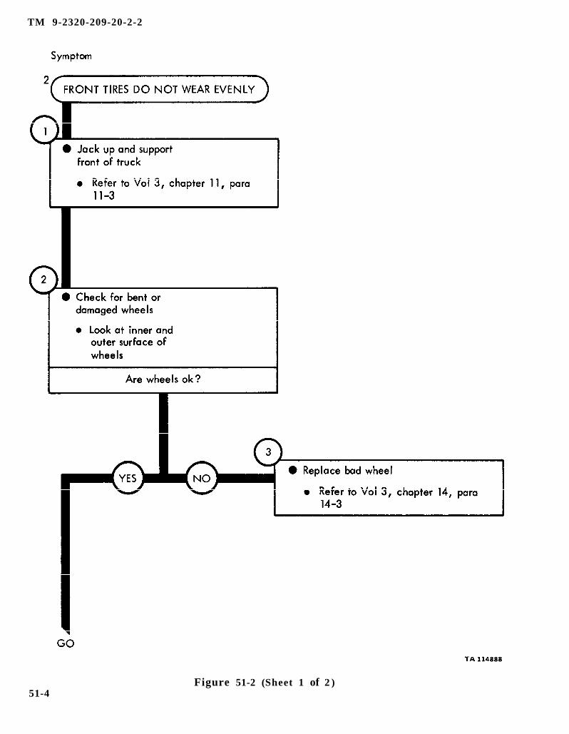
chapter 11 para 11-3
chapter 14 para 14-3
TM 9-2320-209-20-2-2
Figure 51-2 (Sheet 1 of 2 )51-4
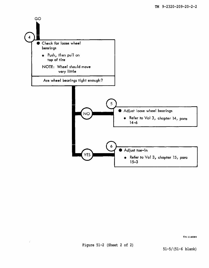
chapter 14 para 14-6
chapter 15 para 15-3
TM 9-2320-209-20-2-2
Figure 51-2 (Sheet 2 of 2)51-5/(51-6 blank)


TM 9-2320-209-20-2-2
CHAPTER 52
STEERING SYSTEM TROUBLESHOOTING
52-1. EQUIPMENT ITEMS COVERED. This chapter gives equipment troubleshootingprocedures for the steering system, for which there are authorized corrective mainte-nance tasks at the organizational maintenance level.
52-2. EQUIPMENT ITEMS NOT COVERED. All equipment items for which correctivemaintenance is authorized at the organizational maintenance level are covered in thischapter.
52-1
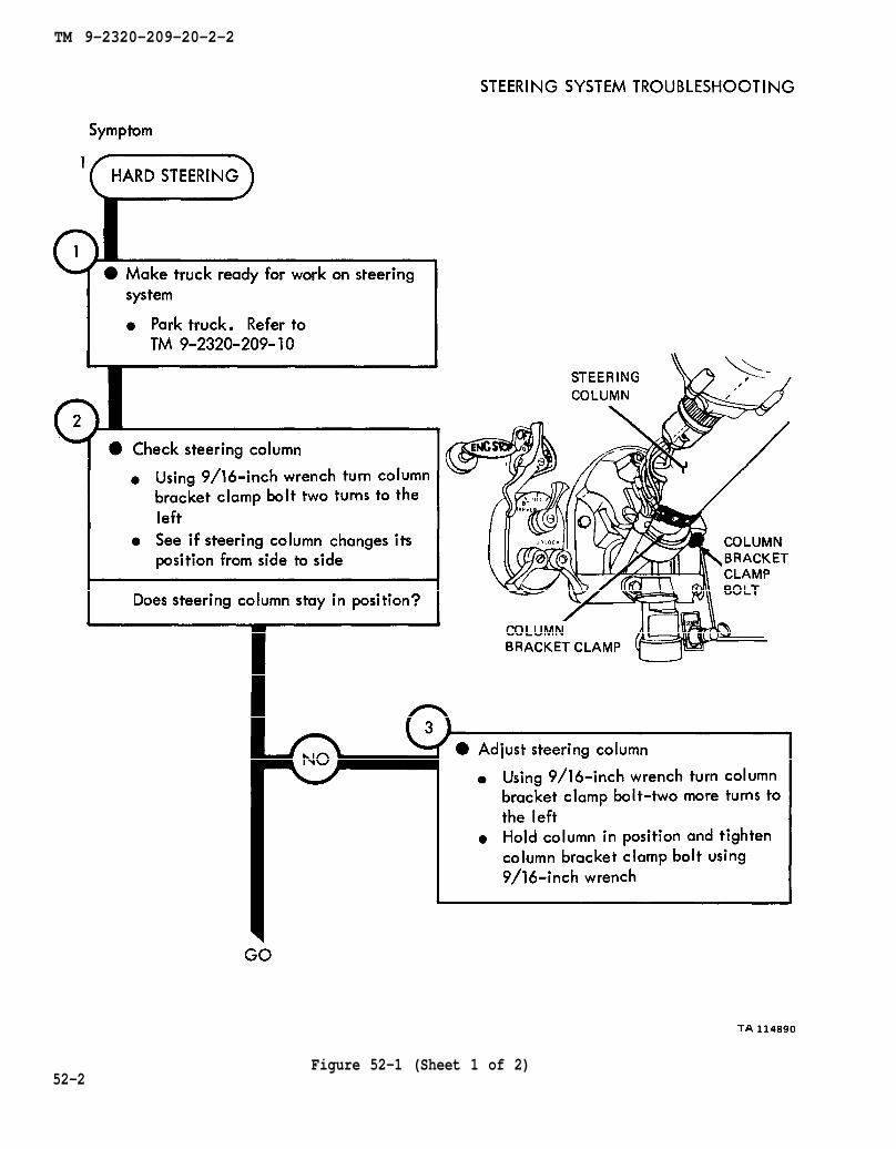
TM 9-2320-209-10
TM 9-2320-209-20-2-2
52-2Figure 52-1 (Sheet 1 of 2)
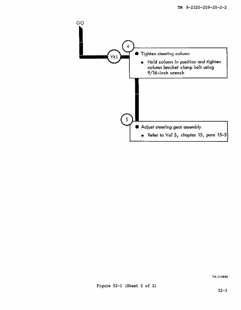
chapter 15 para 15-5
TM 9-2320-209-20-2-2
Figure 52-1 (Sheet 2 of 2)52-3

TM 9-2320-209-10
chapter 15 para 15-7
chapter 15 para 15-9
figure 54-1
figure 54-1
TM 9-2320-209-20-2-2
Figure 52-2 (Sheet 1 of 4)
52-4

chapter 15 para 15-4
figure 54-1
TM 9-2320-209-20-2-2
Figure 52-2 (Sheet 2 of 4)52-5
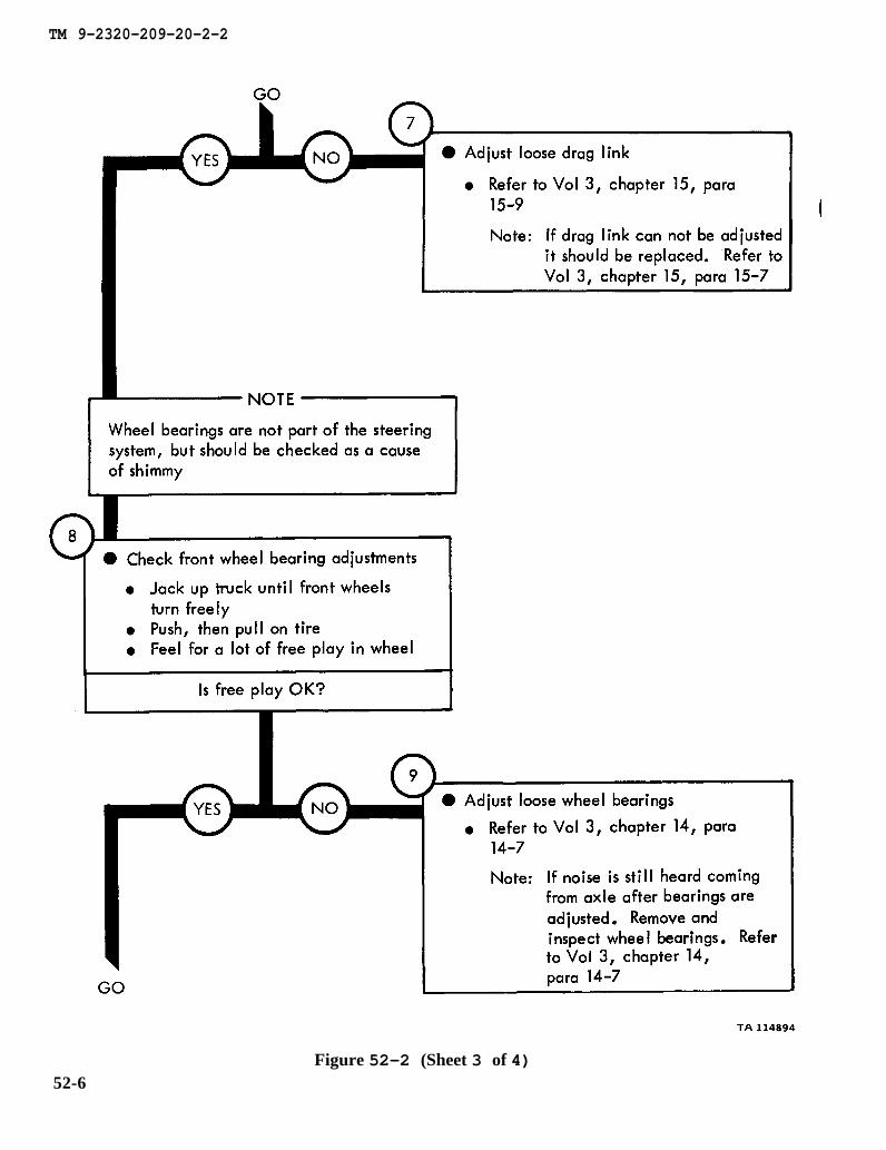
chapter 15 para 15-9
chapter 15 para 15-7
chapter 14 para 14-7
chapter 14
para 14-7
TM 9-2320-209-20-2-2
Figure 52-2 (Sheet 3 of 4)52-6
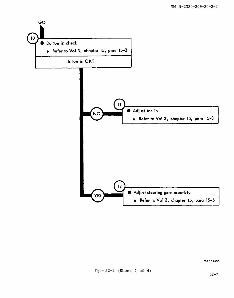
chapter 15 para 15-3
chapter 15 para 15-3
chapter 15 para 15-5
TM 9-2320-209-20-2-2
Figure 52-2 (Sheet 4 of 4)52-7
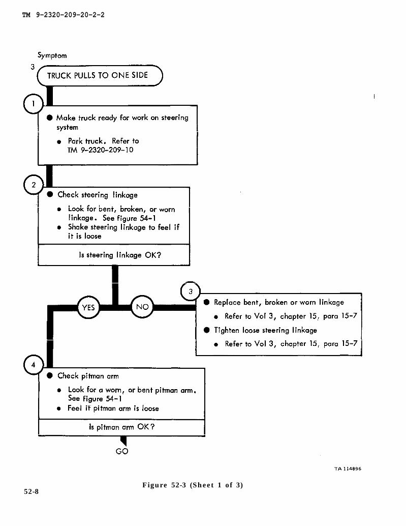
TM 9-2320-209-10
figure 54-1
chapter 15 para 15-7
chapter 15 para 15-7
figure 54-1
TM 9-2320-209-20-2-2
Figure 52-3 (Sheet 1 of 3)52-8

chapter 15 para 15-4
figure 54-1
chapter 15 para 15-9
chapter 15 para 15-7
TM 9-2320-209-20-2-2
Figure 52-3 (Sheet 2 of 3)52-9
chapter 15
chapter 14para 14-7
chapter 14 para 14-7
para 15-3
chapter 15 para 15-3
TM 9-2320-209-20-2-2
Figure 52-3 (Sheet 3 of 3)52-10
TM 9-2320-209-10
chapter 17 para 17-11
TM 9-2320-209-20-2-2
Figure 52-4 (Sheet 1 of 2)52-11
chapter 15 para 15-6
para 15-3 chapter 15
chapter 15 para 15-3
chapter 14
para 14-7
TM 9-2320-209-20-2-2
52-12Figure 52-4 (Sheet 2 of 2)

TM 9-2320-209-20-2-2
CHAPTER 53
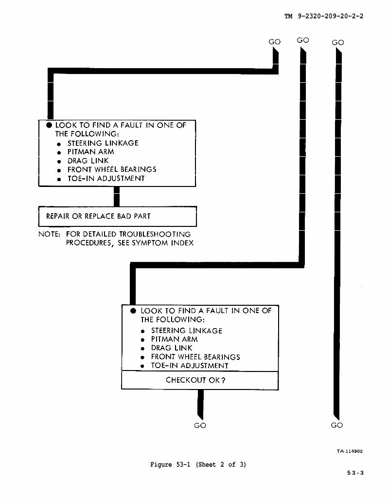
STEERING SYSTEM TROUBLESHOOTING SUMMARY
53-1. GENERAL. This chapter gives a summary of troubleshooting procedures givenin chapter 52 for the steering system.
53-2. PROCEDURES. The summary in this chapter covers all fault symptoms foundin the detailed troubleshooting procedures. Chapter 7 outlines a sample troubleshoot-ing procedure. The summary procedures are based on the “what-to-do” portions ofthe detailed procedures and do not include the “how -to-do-it” instructions. Warn-ings, cautions, and notes are given where needed.
53-1
TM 9-2320-209-20-2-2
Figure 53-1 (Sheet 1 of 3)53-2
TM 9-2320-209-20-2-2
Figure 53-1 (Sheet 2 of 3)5 3 - 3

TM 9-2320-209-20-2-2
53-4Figure 53-1 (Sheet 3 of 3)

TM 9-2320-209-20-2-2
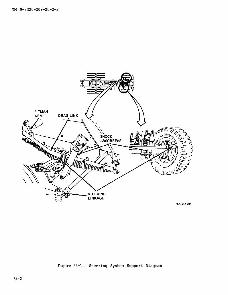
C H A P T E R 5 4
STEERING SYSTEM SUPPORT DIAGRAMS
54-1. GENERAL. This chapter gives the diagrams you need when doing trouble-52. Table 3-1 is a complete listing of all supportshooting procedures in chapter
diagrams used in this manual.
54-1
TM 9-2320-209-20-2-2
Figure 54-1. Steering System Support Diagram
54-2
TM 9-2320-209-20-2-2
CHAPTER 55
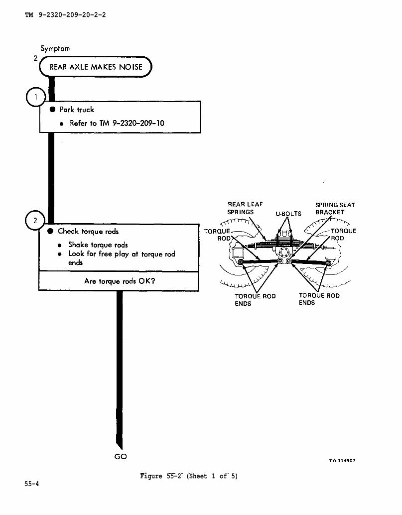
SPRING AND SHOCK ABSORBERS SYSTEM TROUBLESHOOTING
55-1. EQUIPMENT ITEMS COVERED. This chapter gives equipment troubleshootingprocedures for the springs and shock absorbers system, for which there areauthorized corrective maintenance tasks at the organizational maintenance level.
55-2. EQUIPMENT ITEMS NOT COVERED. All equipment items for which correctivemaintenance is authorized at the organizational maintenance level are covered in thischapter.
55-1
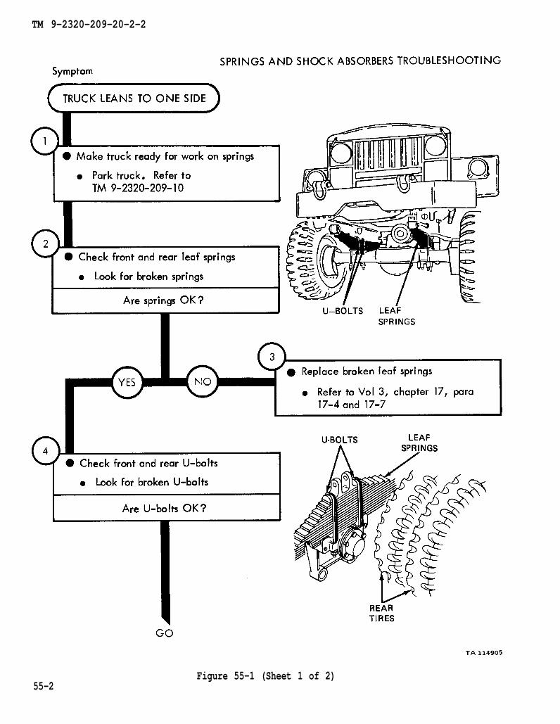
TM 9-2320-209-10
chapter 17 para 17-4
TM 9-2320-209-20-2-2
55-2Figure 55-1 (Sheet 1 of 2)
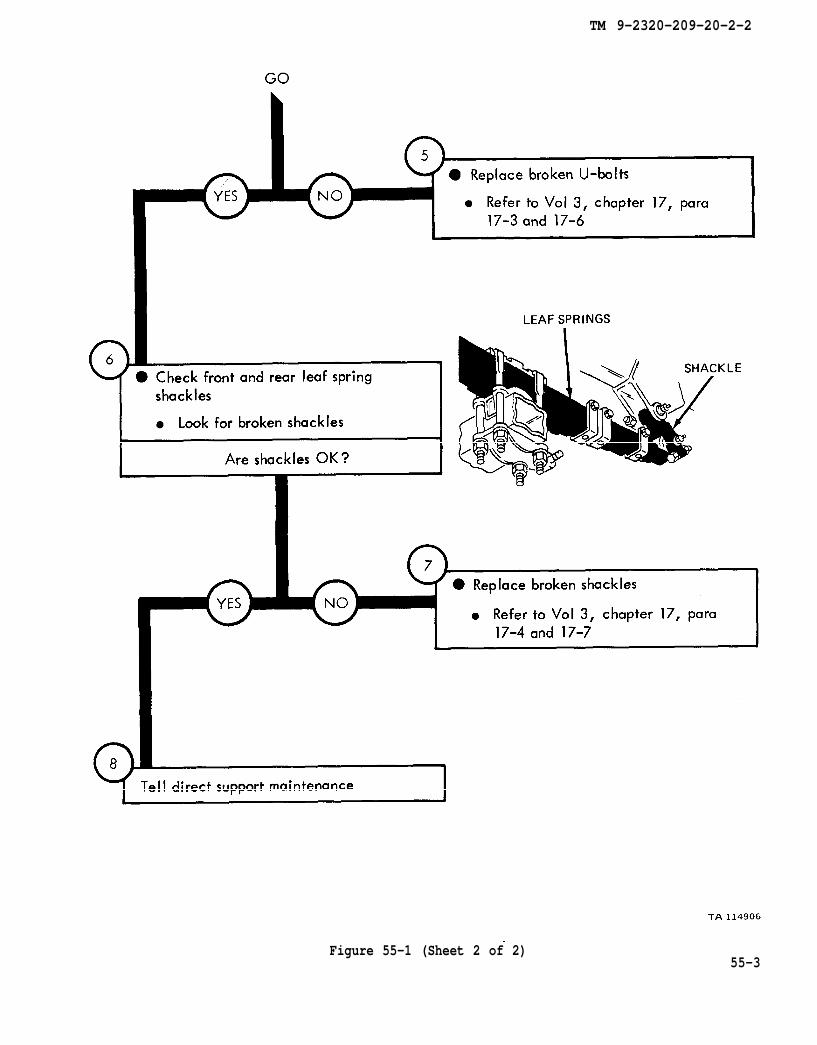
chapter 17 para 17-3
chapter 17 para 17-4
TM 9-2320-209-20-2-2
Figure 55-1 (Sheet 2 of 2)55-3
TM 9-2320-209-10
TM 9-2320-209-20-2-2
Figure 55-2 (Sheet 1 of 5)55-4

chapter 17 para 17-12
TM 9-2320-209-20-2-2
Figure 55-2 (Sheet 2 of 5)55-5

chapter 17 para 17-10
TM 9-2320-209-20-2-2
55-6Figure 55-2 (Sheet 3 of 5)
chapter 14 para 14-10
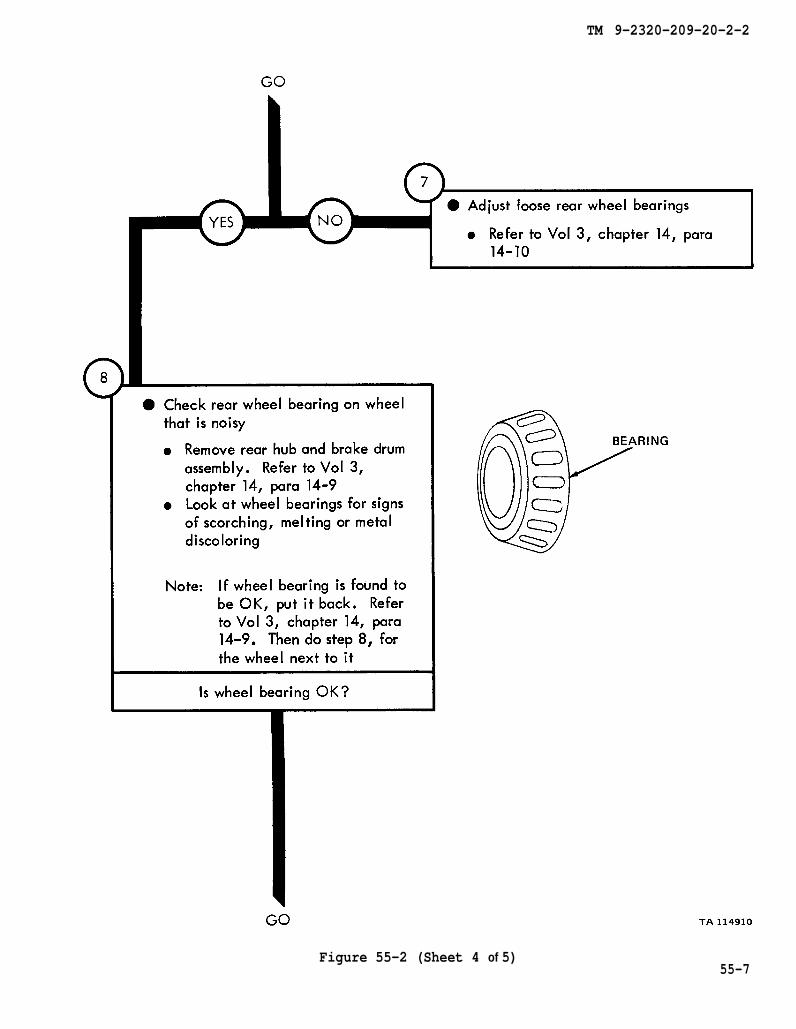
chapter 14 para 14-9
chapter 14 para 14-9
TM 9-2320-209-20-2-2
Figure 55-2 (Sheet 4 of 5)55-7
chapter 14 para 14-10
TM 9-2320-209-20-2-2
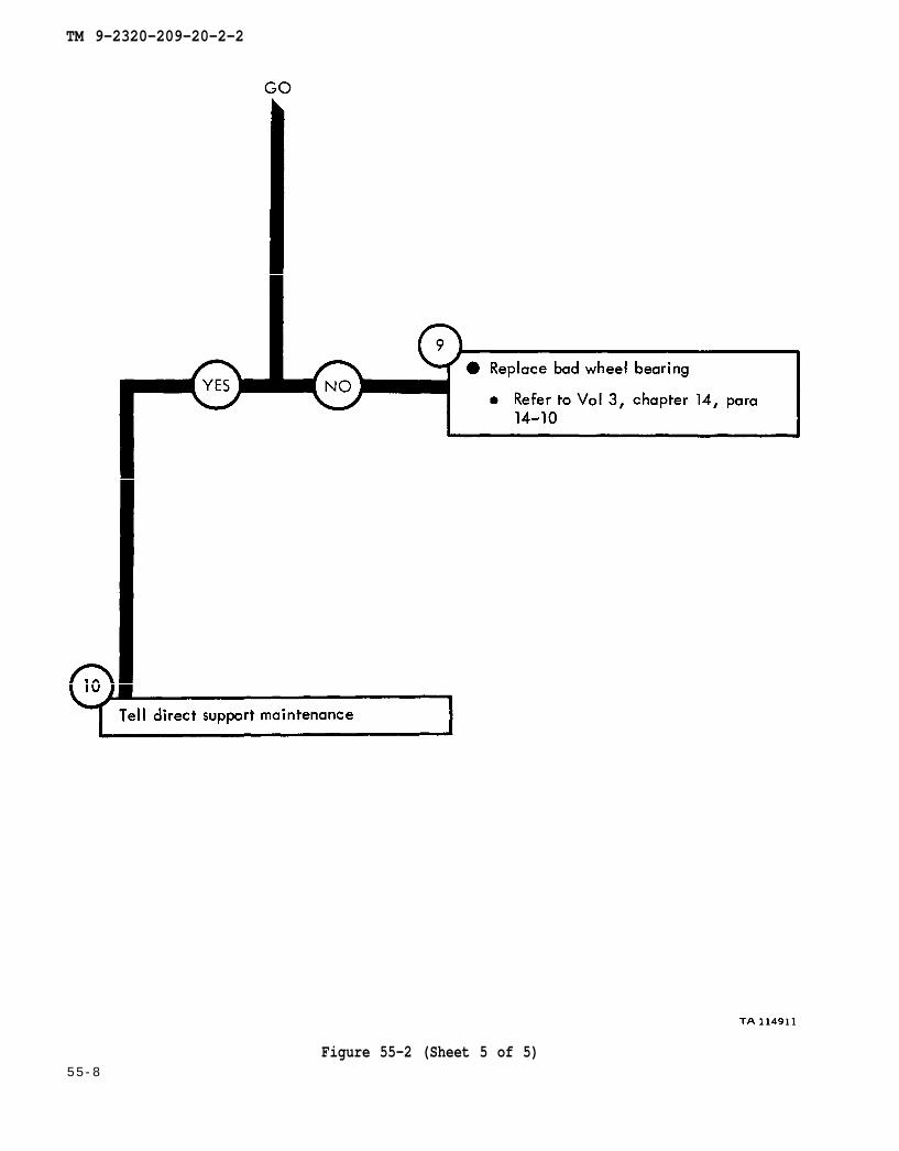
Figure 55-2 (Sheet 5 of 5)5 5 - 8
TM 9-2320-209-20-2-2
CHAPTER 56
SPRING AND SHOCK ABSORBERS SYSTEMTROUBLESHOOTING SUMMARY
56-1. GENERAL. This chapter gives a summary of troubleshooting procedures givenin chapter 55 for the springs and shock absorbers system.
56-2. PROCEDURES. The summary in this chapter covers all fault symptoms foundin the detailed troubleshooting procedures. Chapter 7 outlines a sample troubleshoot-ing procedure. The summary procedures are based on the “what-to-do” portions ofthe detailed procedures and do not include the “how-to-do-it” instructions. Warn-ings, cautions, and notes are given where needed.
56-1
TM 9-2320-209-20-2-2
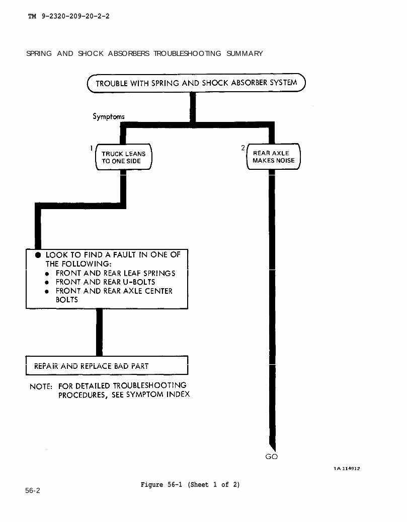
SPRING AND SHOCK ABSORBERS TROUBLESHOOTING SUMMARY
56-2Figure 56-1 (Sheet 1 of 2)
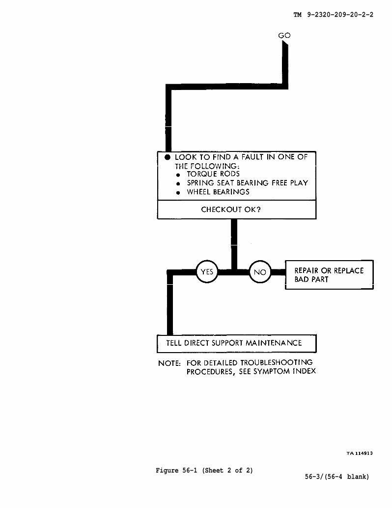
TM 9-2320-209-20-2-2
Figure 56-1 (Sheet 2 of 2)56-3/(56-4 blank)

TM 9-2320-209-20-2-2
CHAPTER 57
DUMP BODY TROUBLESHOOTING
57-1. EQUIPMENT ITEMS COVERED. This chapter gives equipment troubleshootingprocedures for the dump body, for which there are authorized corrective maintenancetasks at the organizational maintenance level.
57-2. EQUIPMENT ITEMS NOT COVERED. All equipment items for which correctivemaintenance is authorized at the organizational maintenance level are covered in thischapter.
57-1

TM 9-2320-209-10
figure 59-1
chapter 10 para 10-4
TM 9-2320-209-20-2-2
57-2Figure 57-1 (Sheet 1 of 4)
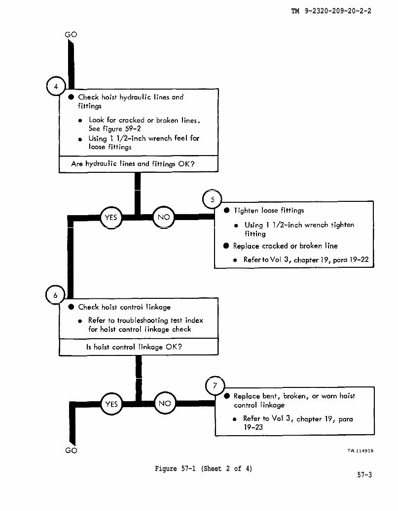
chapter 19 para 19-22
chapter 19 para 19-23
TM 9-2320-209-20-2-2
Figure 57-1 (Sheet 2 of 4)57-3

chapter 19 para 19-23
TM 9-2320-209-10
TM 9-2320-209-10
figure 59-1
TM 9-2320-209-20-2-2
57-4 Figure 57-1 (Sheet 3 of 4)
TM 9-2320-209-20-2-2
Figure 57-1 (Sheet 4 of 4)57-5

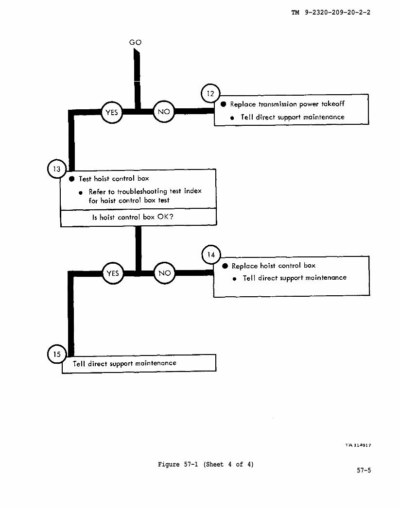
TM 9-2320-209-10
TM 9-2320-209-10
figure 59-2
chapter 19 para 19-22
TM 9-2320-209-20-2-2
57-6 Figure 57-2 (Sheet 1 of 2)

chapter 14 para 19-23
chapter 19 para 19-23
TM 9-2320-209-20-2-2
Figure 57-2 (Sheet 2 of 2)57-7

TM 9-2320-209-10
TM 9-2320-209-10
figure 59-2
chapter 19 para 19-22
TM 9-2320-209-20-2-2
57-8 Figure 57-3 (Sheet 1 of 2)

TM 9-2320-209-10-1
TM 9-2320-209-20-2-2
Figure 57-3 (Sheet 2 of 2)57-9
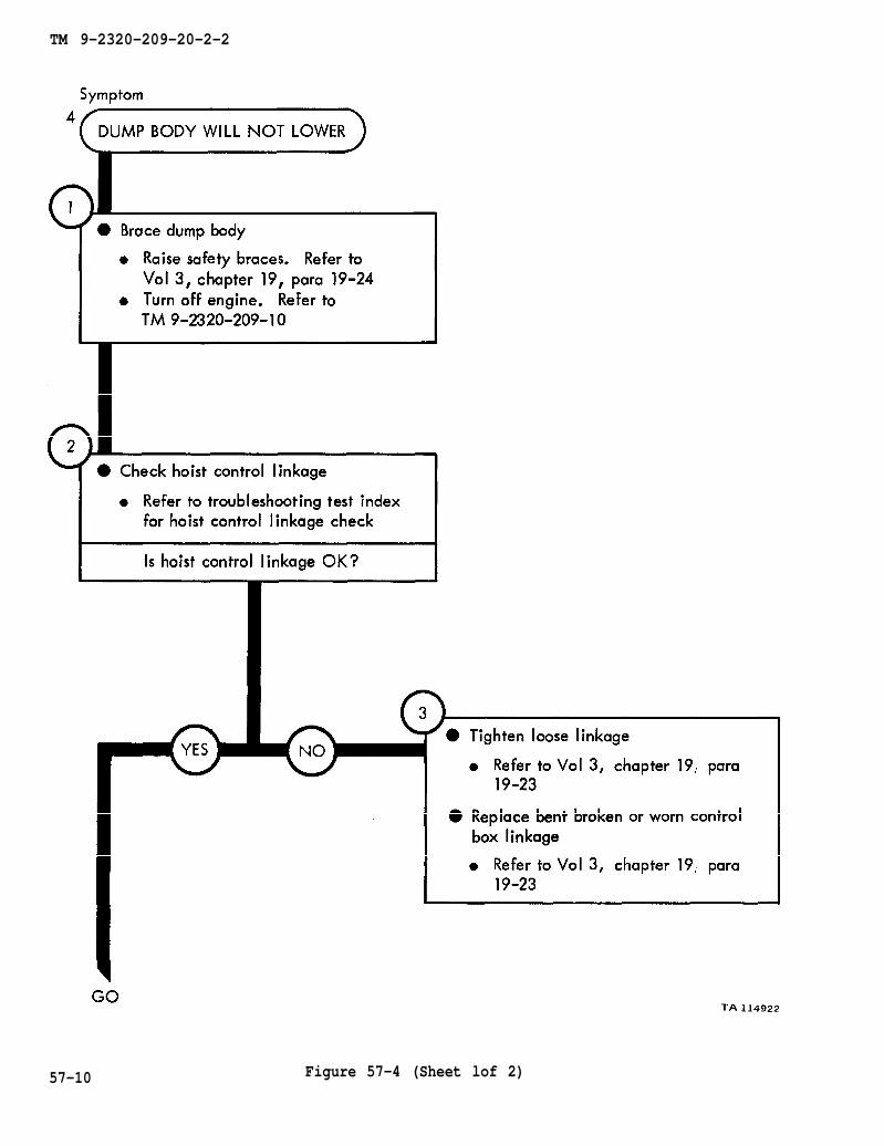
chapter 19 para 19-24
TM 9-2320-209-10
chapter 19 para 19-23
para 19-23 chapter 19
TM 9-2320-209-20-2-2
57-10 Figure 57-4 (Sheet lof 2)

chapter 19 para 19-23
TM 9-2320-209-20-2-2
Figure 57-4 (Sheet 2 of 2)57-11

TM 9-2320-209-10
chapter 19 para 19-23
TM 9-2320-209-20-2-2
Figure 57-5 (Sheet 1 of 2)5 7 - 1 2

TM 9-2320-209-20-2-2
57-13Figure 57-5 (Sheet 2 of 2)

figure 59-1
TM 9-2320-209-20-2-2
57-14Figure 57-6
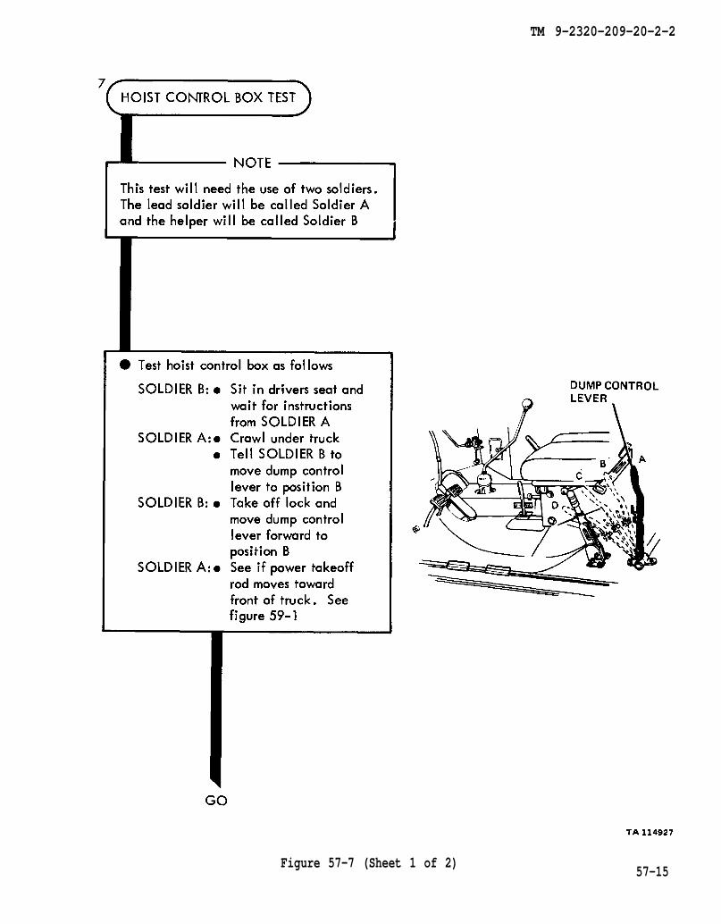
figure 59-1
TM 9-2320-209-20-2-2
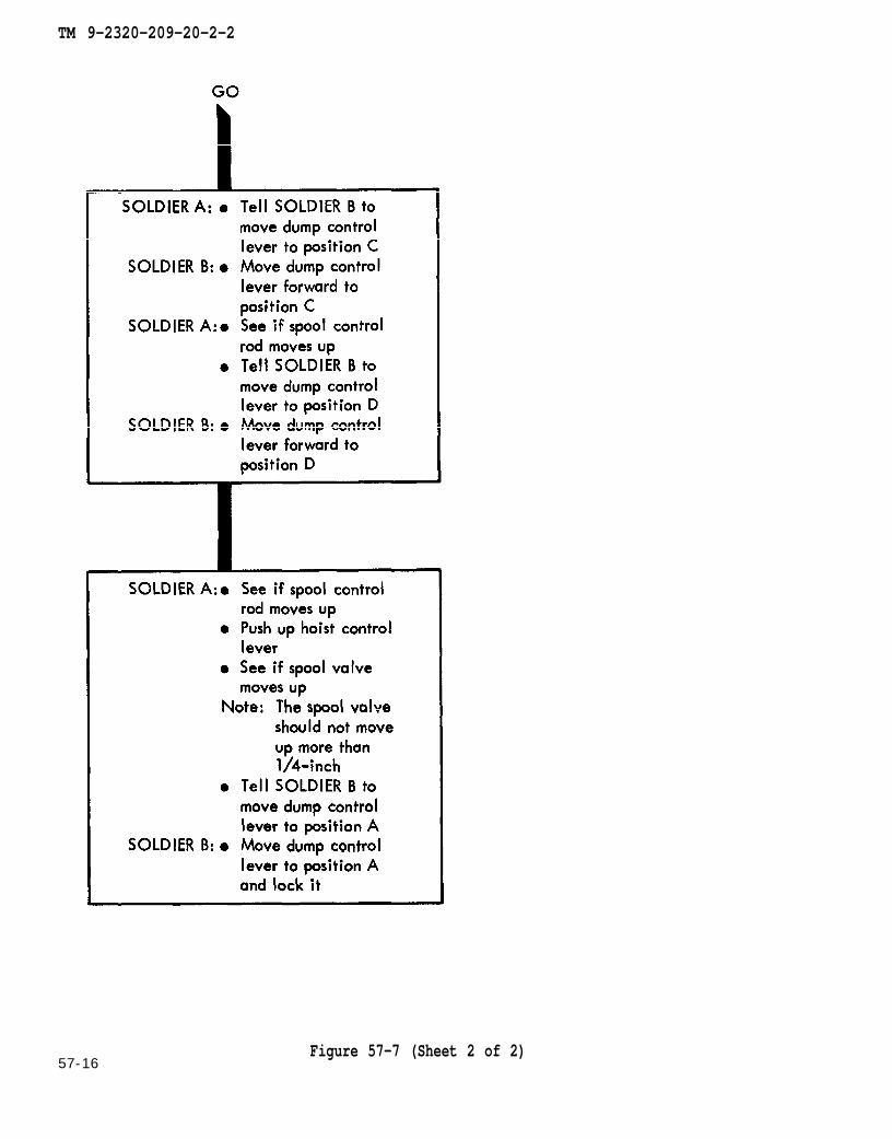
Figure 57-7 (Sheet 1 of 2)57-15
TM 9-2320-209-20-2-2
57-16Figure 57-7 (Sheet 2 of 2)

chapter 19
para 19-23
TM 9-2320-209-20-2-2
Figure 57-857-17/(57-18 blank)


TM 9-2320-209-20-2-2
CHAPTER 58
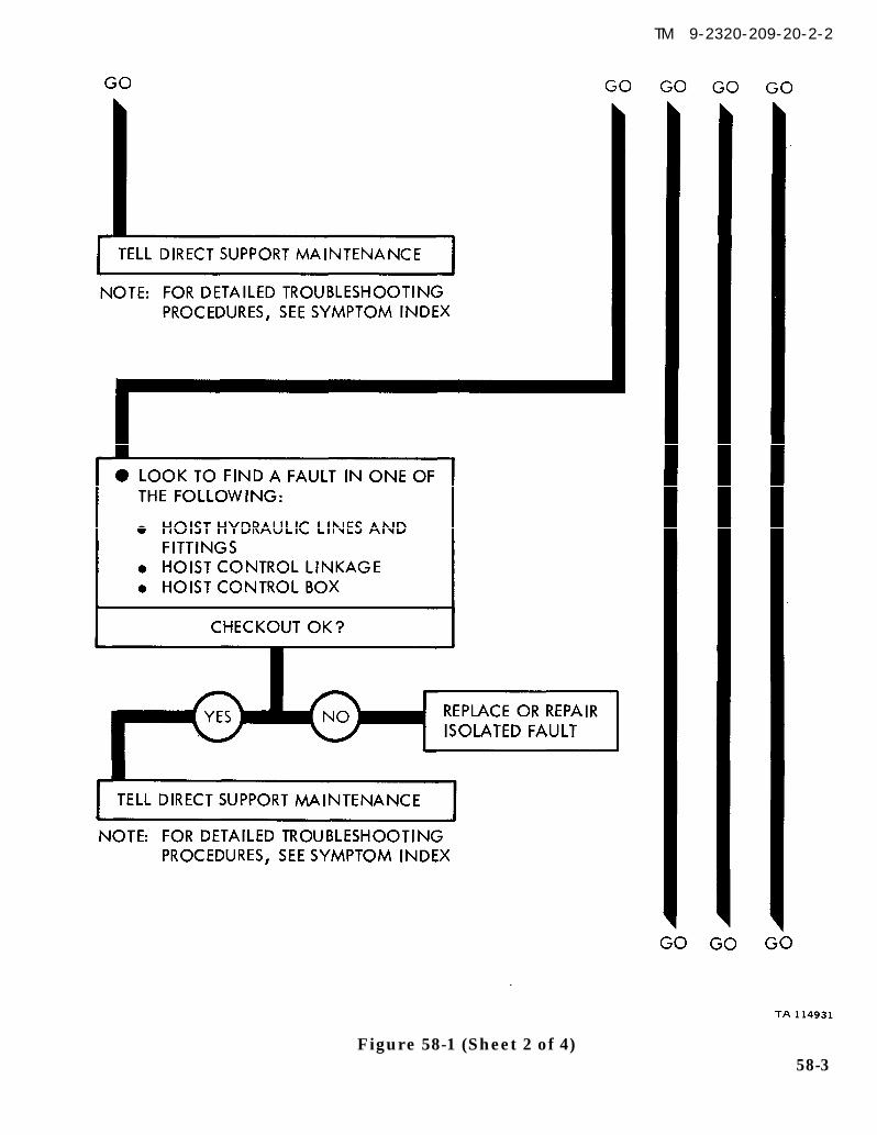
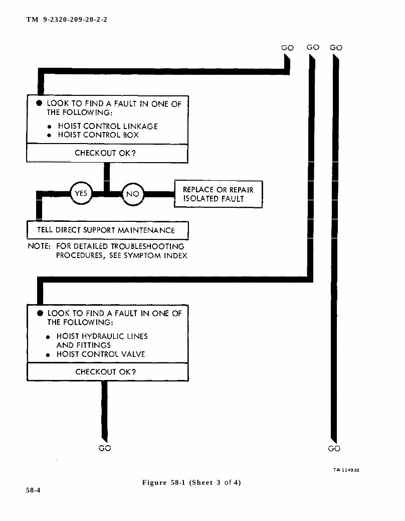
DUMP BODY TROUBLESHOOTING SUMMARY
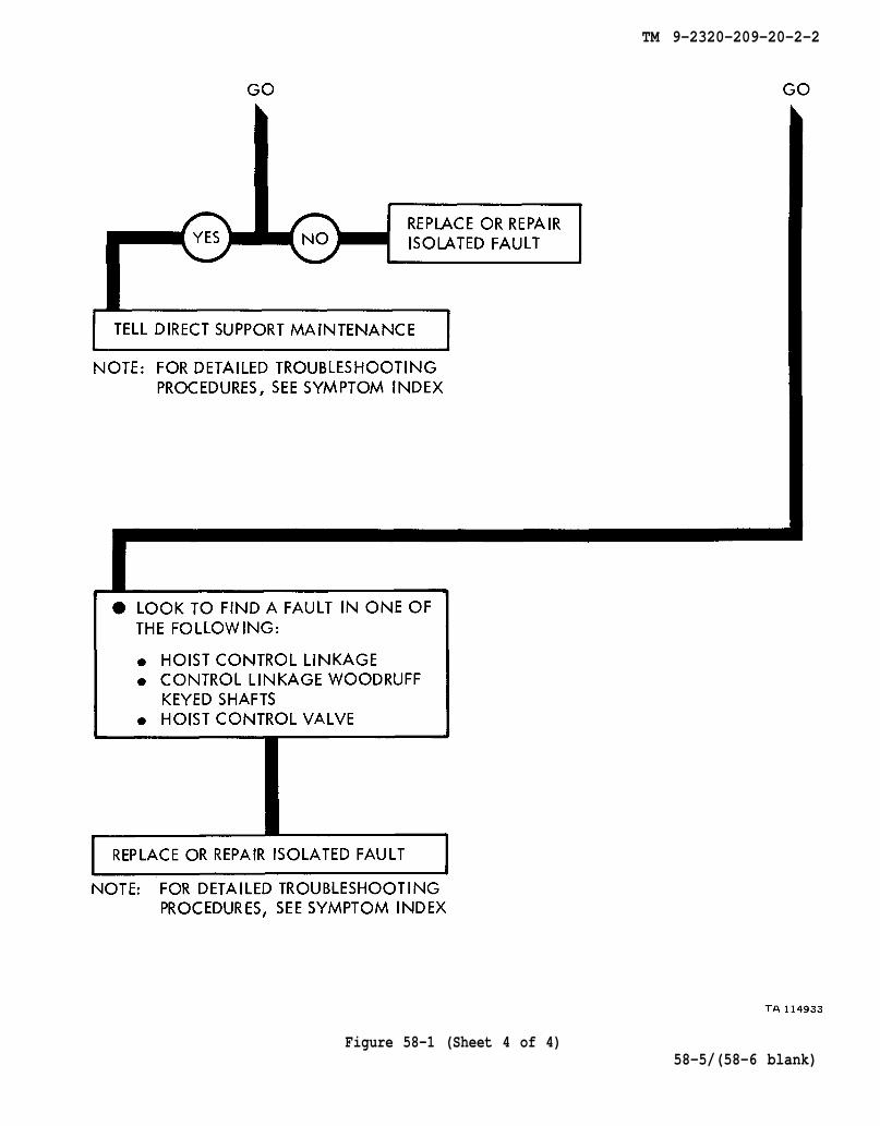
58-1. GENERAL. This chapter gives a summary of troubleshooting procedures givenin chapter 57 for the dump body.
58-2. PROCEDURES. The summary in this chapter covers all fault symptoms foundin the detailed troubleshooting procedures. Chapter 7 outlines a sample troubleshoot-ing procedure. The summary procedures are based on the “what-to-do” portions ofthe detailed procedures and do not include the “how-to-do-it” instructions. Warn-ings, cautions, and notes are given where needed.
58-1
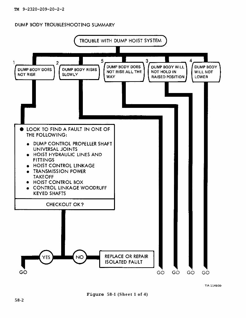
TM 9-2320-209-20-2-2
Figure 58-1 (Sheet 1 of 4)58-2
TM 9-2320-209-20-2-2
Figure 58-1 (Sheet 2 of 4)58-3
TM 9-2320-209-20-2-2
Figure 58-1 (Sheet 3 of 4)58-4
TM 9-2320-209-20-2-2
Figure 58-1 (Sheet 4 of 4)58-5/(58-6 blank)

TM 9-2320-209-20-2-2
CHAPTER 59
DUMP BODY SUPPORT DIAGRAMS
59-1 GENERAL. This chapter gives the diagrams you need when doing trouble-shooting procedures in chapter 57. Table 3-1 is a complete listing of all supportdiagrams used in this manual.
59-1
TM 9-2320-209-20-2-2
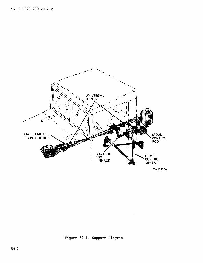
Figure 59-1. Support Diagram
59-2

TM 9-2320-209-20-2-2
Figure 59-2. Support Diagram
59-3/ (59-4 blank)

TM 9-2320-209-20-2-2
CHAPTER 60
DUMP BODY CHECKOUT PROCEDURES
60-1. GENERAL. This chapter gives procedures for checking out the system aftertroubleshooting and repair have been done. Procedures are set up in flow chart formshowing the checkout steps in order and referring to the fault symptom index whenthe system does not checkout.
60-1
TM 9-2320-209-10
TM 9-2320-209-20-2-2
60-2Figure 60-1 (Sheet 1 of 2)
TM 9-2320-209-10
TM 9-2320-209-10
TM 9-2320-209-20-2-2
Figure 60-1 (Sheet 2 of 2)
60-3/(60-4 blank)


TM 9-2320-209-20-2-2
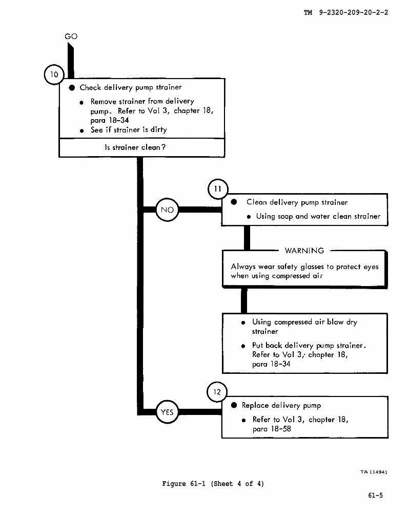
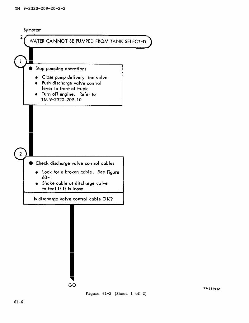
CHAPTER 61
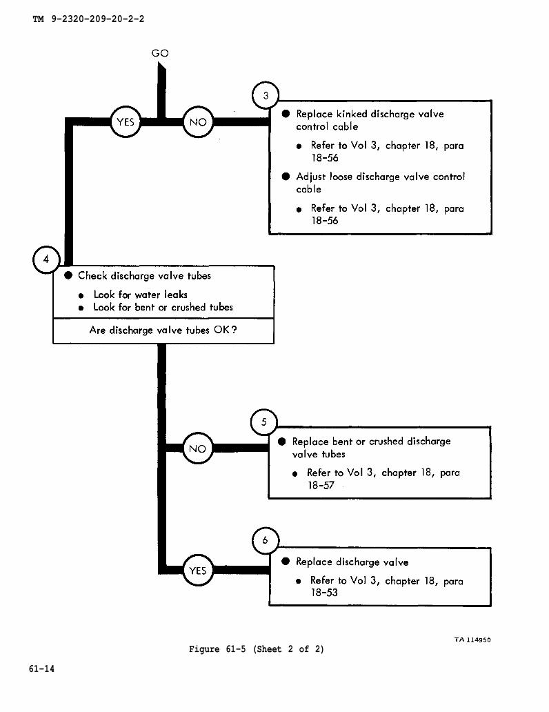
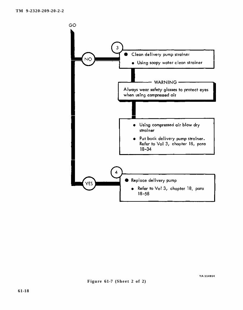
WATER TANK BODY TROUBLESHOOTING
61-1. EQUIPMENT ITEMS COVERED. This chapter gives equipment troubleshootingprocedures for the water tank body, for which there are authorized corrective mainte-nance tasks at the organizational maintenance level.
61-2. EQUIPMENT ITEMS NOT COVERED. All equipment items for which correctivemaintenance is authorized at the organizational maintenance level are covered in thischapter.
61-1

TM 9-2320-209-10
figure 63-1
chapter 18
chapter 18
para 18-36
para 18-35
TM 9-2320-209-20-2-2
Figure 61-1 (Sheet 1 of 4)61-2

chapter 18
chapter 18
para 18-58
para 18-58
TM 9-2320-209-20-2-2
Figure 61-1 (Sheet 2 of 4)
61-3

chapter 19 para 19-25
TM 9-2320-209-10
TM 9-2320-209-10
TM 9-2320-209-20-2-2
Figure 61-1 (Sheet 3 of 4)
61-4
chapter 18
para 18-34
chapter 18
para 18-34
chapter 18
para 18-58
TM 9-2320-209-20-2-2
Figure 61-1 (Sheet 4 of 4)
61-5
TM 9-2320-209-10
figure 63-1
TM 9-2320-209-20-2-2
Figure 61-2 (Sheet 1 of 2)
61-6
chapter 18
chapter 18
para 18-56
para 18-56
chapter 18
chapter 18
para 18-57
para 18-53
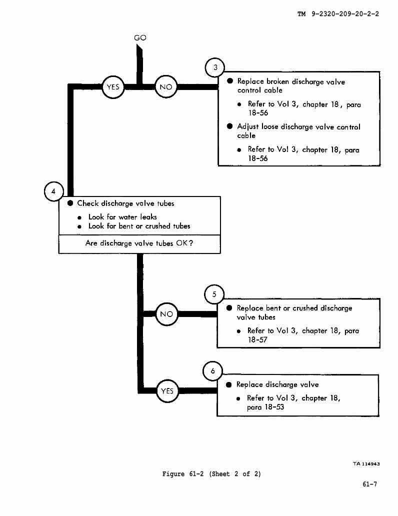
TM 9-2320-209-20-2-2
Figure 61-2 (Sheet 2 of 2)
61-7

TM 9-2320-209-10
chapter 18 para 18-34
TM 9-2320-209-20-2-2
Figure 61-3 (Sheet 1 of 3)
61-8
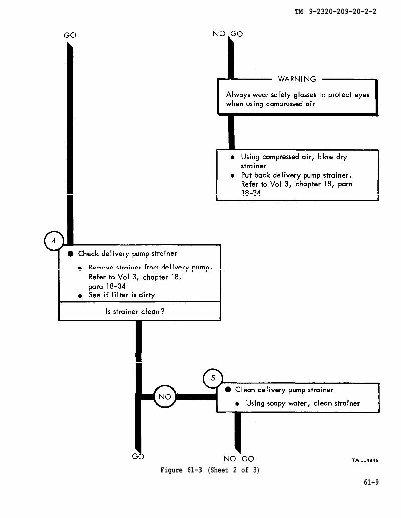
chapter 18 para 18-34
chapter 18
para 18-34
TM 9-2320-209-20-2-2
Figure 61-3 (Sheet 2 of 3)
61-9
chapter 18 para 18-34
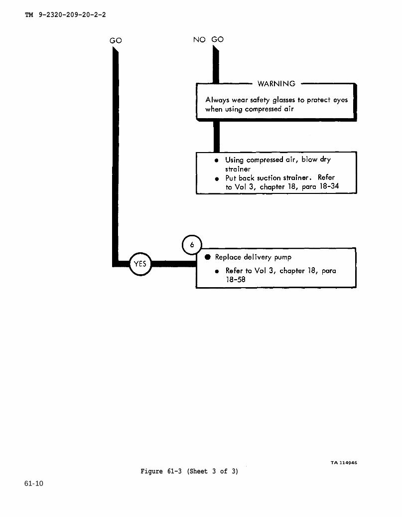
chapter 18 para 18-58
TM 9-2320-209-20-2-2
Figure 61-3 (Sheet 3 of 3)
61-10

figure 63-1
TM 9-2320-209-20-2-2
Figure 61-4 (Sheet 1 of 2)
6 1 - 1 1
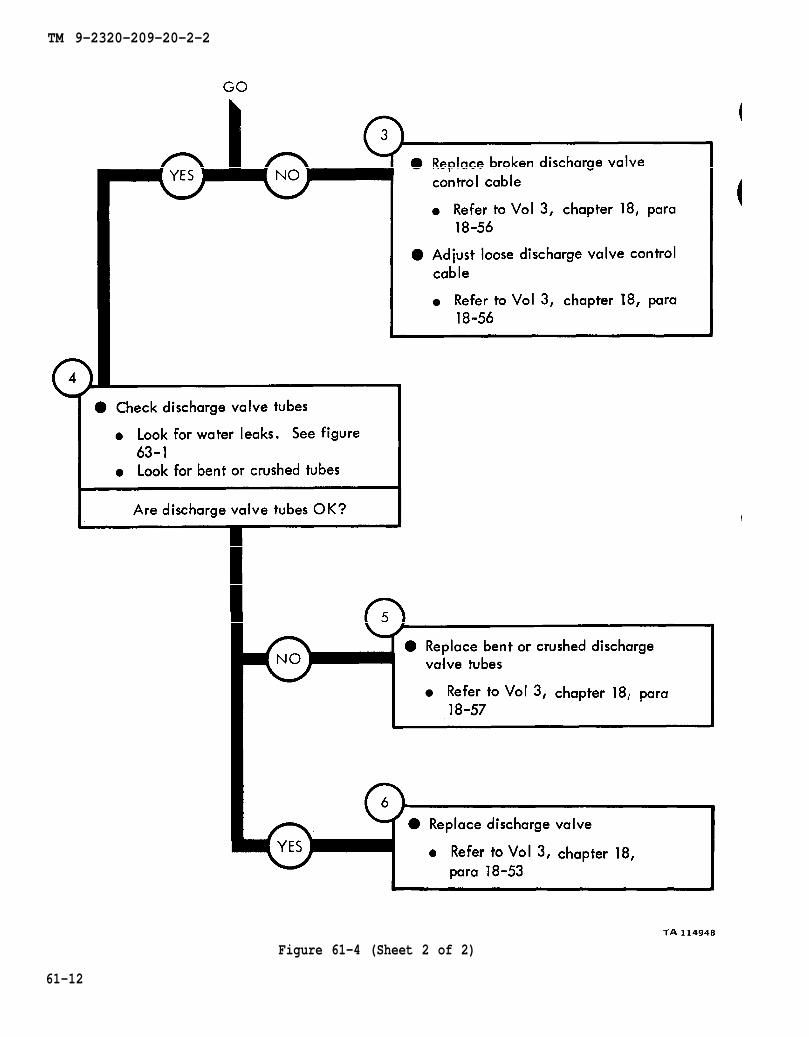
chapter 18
chapter 18
para 18-56
para 18-56
figure 63-1
chapter 18 para 18-57
chapter 18
para 18-53
TM 9-2320-209-20-2-2
Figure 61-4 (Sheet 2 of 2)
61-12
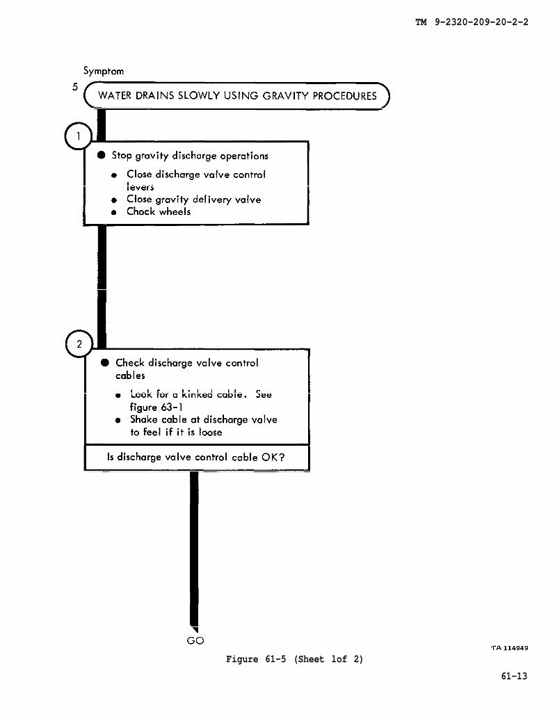
figure 63-1
TM 9-2320-209-20-2-2
Figure 61-5 (Sheet lof 2)
61-13
chapter 18
chapter 18
para 18-56
para 18-56
chapter 18
chapter 18
para 18-57
para 18-53
TM 9-2320-209-20-2-2
Figure 61-5 (Sheet 2 of 2)
61-14

TM 9-2320-209-10
figure 63-1
TM 9-2320-209-20-2-2
Figure 61-6 (Sheet 1 of 2)
61-15

chapter 18
chapter 18
para 18-56
para 18-56
chapter 18
chapter 18
para 18-57
para 18-53
TM 9-2320-209-20-2-2
Figure 61-6 (Sheet 2of 2)
61-16

TM 9-2320-209-10
chapter 18 para 18-34
TM 9-2320-209-20-2-2
Figure 61-7 (Sheet 1 of 2)
61-17
chapter 18
chapter 18
para 18-34
para 18-58
TM 9-2320-209-20-2-2
Figure 61-7 (Sheet 2 of 2)
61-18
TM 9-2320-209-20-2-2
CHAPTER 62
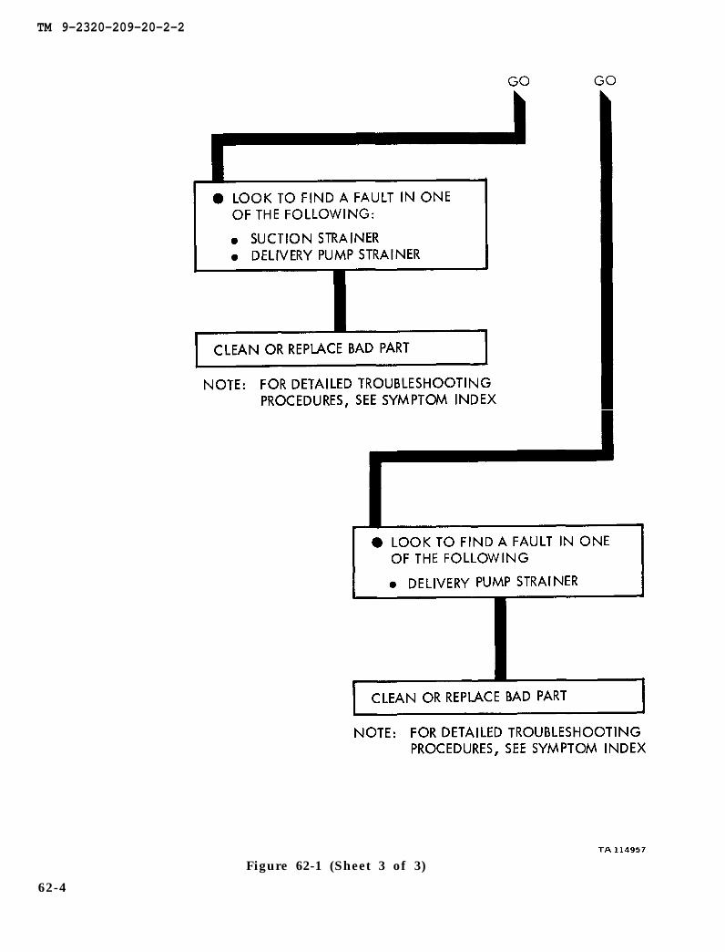
WATER TANK BODY TROUBLESHOOTING SUMMARY
62-1. GENERAL. This chapter gives a summary of troubleshooting procedures givenin chapter 61 for the water tank body.
62-2. PROCEDURES. The summary in this chapter covers all fault symptoms foundin the detailed troubleshooting procedures. Chapter 7 outlines a sample troubleshoot-ing procedure. The summary procedures are based on the “what-to-do” portions ofthe detailed procedures and do not include the “how-to-do-it” instructions. Warn-ings, cautions, and notes are given where needed.
62-1

TM 9-2320-209-20-2-2
WATER TANK BODY TROUBLESHOOTING SUMMARY
62-2
Figure 62-1 (Sheet 1 of 3)

TM 9-2320-209-20-2-2
Figure 62-1 (Sheet 2 of 3)
62-3
TM 9-2320-209-20-2-2
Figure 62-1 (Sheet 3 of 3)
62-4
TM 9-2320-209-20-2-2
CHAPTER 63
WATER TANK BODY SUPPORT DIAGRAMS
63-1. GENERAL. This chapter gives the diagrams you need when doing trouble-shooting procedures in chapterdiagrams used in this manual.
61. Table 3-1 is a complete listing of all support
63-1
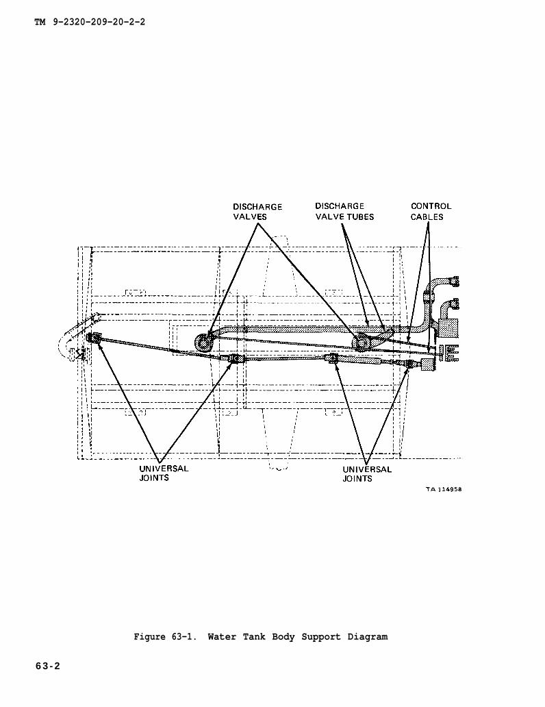
TM 9-2320-209-20-2-2
Figure 63-1. Water Tank Body Support Diagram
6 3 - 2

TM 9-2320-209-20-2-2
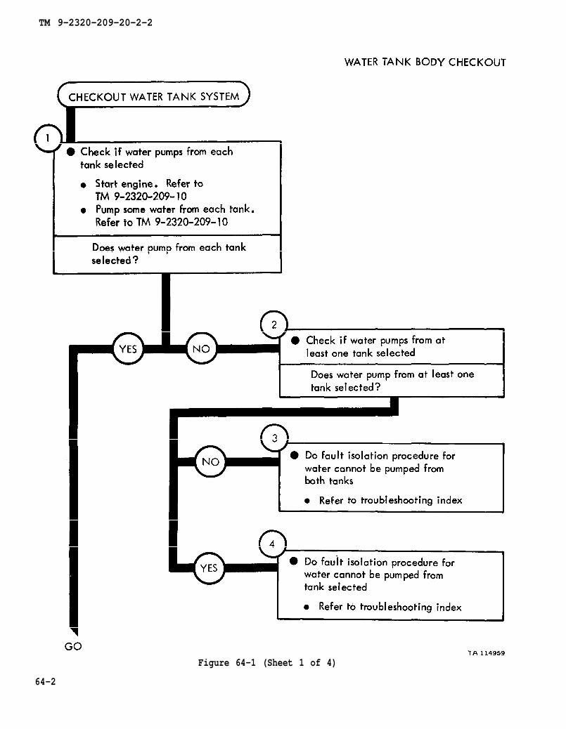
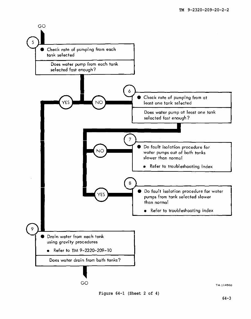
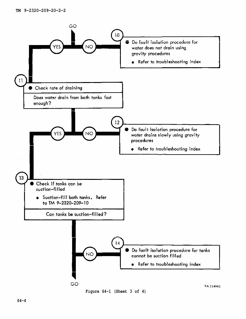
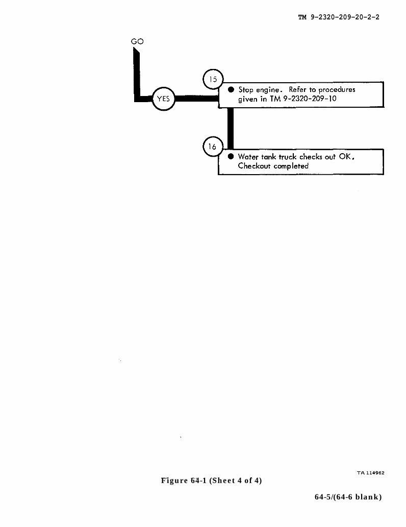
CHAPTER 64
WATER TANK BODY CHECKOUT PROCEDURES
64-1. GENERAL. This chapter gives procedures for checking out the system aftertroubleshooting and repair have been done. Procedures are set up in flow chart formshowing the checkout steps in order and referring to the fault symptom index when thesystem does not checkout.
64-1
TM 9-2320-209-10
TM 9-2320-209-10
TM 9-2320-209-20-2-2
Figure 64-1 (Sheet 1 of 4)
64-2
TM 9-2320-209-10
TM 9-2320-209-20-2-2
Figure 64-1 (Sheet 2 of 4)64-3
TM 9-2320-209-10
TM 9-2320-209-20-2-2
Figure 64-1 (Sheet 3 of 4)
64-4
TM 9-2320-209-10
TM 9-2320-209-20-2-2
Figure 64-1 (Sheet 4 of 4)
64-5/(64-6 blank)


TM 9-2320-209-20-2-2
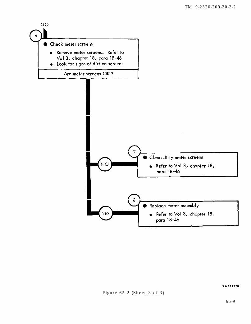
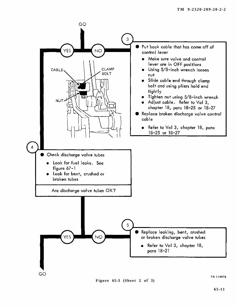
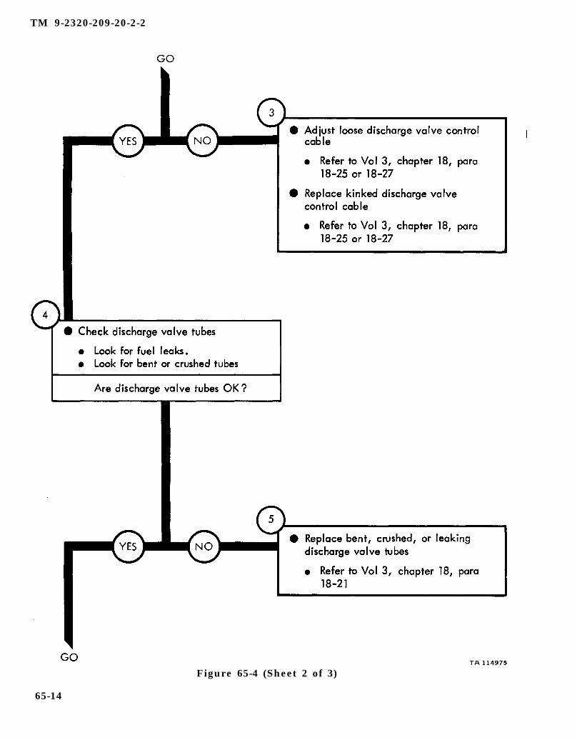
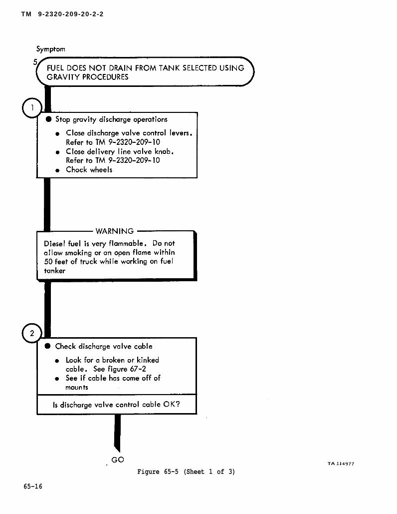
CHAPTER 65
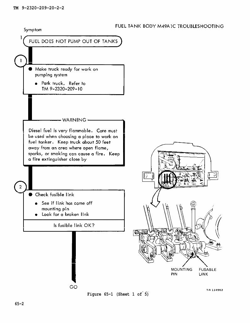
FUEL TANK BODY (TRUCK M49A1C) TROUBLESHOOTING
65-1. EQUIPMENT ITEMS COVERED. This chapter gives equipment troubleshootingprocedures for the fuel tank body M49AlC, for which there are authorized correctivemaintenance tasks at the organizational maintenance level.
65-2. EQUIPMENT ITEMS NOT COVERED. All equipment items for which correctivemaintenance is authorized at the organizational maintenance level are covered in thischapter.
65-1
TM 9-2320-209-10
TM 9-2320-209-20-2-2
65-2
Figure 65-1 (Sheet 1 of 5)

chapter 18 para 18-30
TM 9-2320-209-20-2-2
Figure 65-1 (Sheet 2 of 5)
65-3
chapter 19
para 19-25
chapter 19
para 19-25
TM 9-2320-209-10
TM 9-2320-209-10
TM 9-2320-209-20-2-2
65-4
Figure 65-1 (Sheet 3 of 5)
chapter 18
chapter 18
para 18-36
para 18-35
TM 9-2320-209-10
TM 9-2320-209-20-2-2
Figure 65-1 (Sheet 4 of 5)
65-5
para 18-33
chapter 18
para 18-46 chapter 18
para 18-46
para 18-46
chapter 18
chapter 18
TM 9-2320-209-20-2-2
Figure 65-1 (Sheet 5 of 5)
65-6
TM 9-2320-209-10
TM 9-2320-209-20-2-2
Figure 65-2 (Sheet 1 of 3)
65-7

chapte 18
para 18-42
TM 9-2320-209-10
para 18-34
chapter 18
chapter 18 para 18-33
TM 9-2320-209-20-2-2
Figure 65-2 (Sheet 2 of 3)
65-8
chapter 18 para 18-46
chapter 18
para 18-46
para 18-46
chapter 18
TM 9-2320-209-20-2-2
Figure 65-2 (Sheet 3 of 3)
65-9
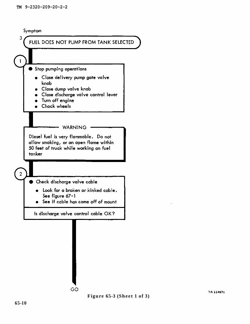
figure 67-1
TM 9-2320-209-20-2-2
Figure 65-3 (Sheet 1 of 3)65-10
chapter 18 para 18-25
chapter 18 para 18-25
figure 67-1
chapter 18
para 18-21
TM 9-2320-209-20-2-2
Figure 65-3 (Sheet 2 of 3)
65-11

TM 9-2320-209-20-2-2
Figure 65-3 (Sheet 3 of 3)
65-12

figure 67-1
TM 9-2320-209-20-2-2
Figure 65-4 (Sheet 1 of 3)
65-13
chapter 18 para 18-25
para 18-25 chapter 18
chapter 18 para 18-21
TM 9-2320-209-20-2-2
65-14
Figure 65-4 (Sheet 2 of 3)
TM 9-2320-209-20-2-2
Figure 65-4 (Sheet 3 of 3)
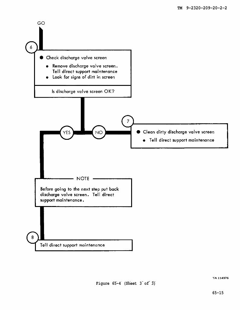
65-15
TM 9-2320-209-10
TM 9-2320-209-10
figure67-2
TM 9-2320-209-20-2-2
Figure 65-5 (Sheet 1 of 3)
65-16

TM 9-2320-209-20-2-2
● Put back cable that has come off ofdischarge valve
●
●
●
●
●
Make sure valve and control leversare in OFF positions. Refer toTM 9-2320-209-10Using 1/2-inch wrench loosen twonuts on U-boltSlide cable end through U-boltand using pliers hold end tightlyTighten two nuts on U-bolt using1/2-inch wrenchAdjust cables. Refer to Vol 3,chapter 18, para 18-25 or18-27
• Put back cable that has come offcontrol lever
●
●
●
●
●
Make sure valve and control leverare in OFF positions. Refer toTM 9-2320-209-10Using 5/8-inch wrench loosen nutSlide cable end through clampbolt and using pliers hold endtightlyTighten nut using 5/8-inch wrenchAdjust cables. Refer to Vol 3,chapter 18, para 18-25 or 18-27
Ž Replace broken discharge valve controlcable
● Refer to Vol 3, chapter 18, para18-25 or 18-27
Figure 65-5 (Sheet 2 of 3)TA 114978
65-17

figure 67-2
chapter 18
chapter 18
para 18-21
para 18-19
TM 9-2320-209-20-2-2
Figure 65-5 (Sheet 3 of 3)
65-18
TM 9-2320-209-10
TM 9-2320-209-10
figure 67-2
TM 9-2320-209-20-2-2
Figure 65-6 (Sheet 1 of 3)
65-19

chapter 18 para 18-25
chapter 18 para 18-25
chapter 18 para 18-21
TM 9-2320-209-20-2-2
Figure 65-6 (Sheet 2 of 3)
65-20
chapter 18 para 18-19
TM 9-2320-209-20-2-2
Figure 65-6 (Sheet 3 of 3)
65-21
TM 9-2320-209-10
chapter 18 para 18-30
TM 9-2320-209-20-2-2
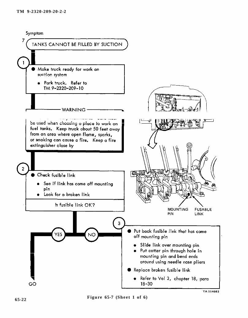
65-22 Figure 65-7 (Sheet 1 of 6)

TM 9-2320-209-20-2-2
Figure 65-7 (Sheet 2 of 6)
65-23

chapter 19
para 19-25
chapter 19
para 19-25
TM 9-2320-209-10
TM 9-2320-209-20-2-2
Figure 65-7 (Sheet 3 of 6)65-24
TM 9-2320-209-10
chapter 18
para 18-36
para 18-35
chapter 18
TM 9-2320-209-20-2-2
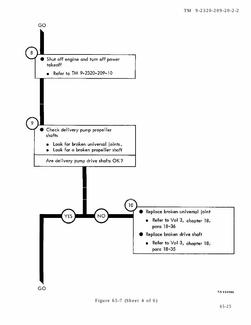
Figure 65-7 (Sheet 4 of 6)65-25
TM 9-2320-209-10
chapter 18
para 18-33
chapter 18 para 18-46
TM 9-2320-209-20-2-2
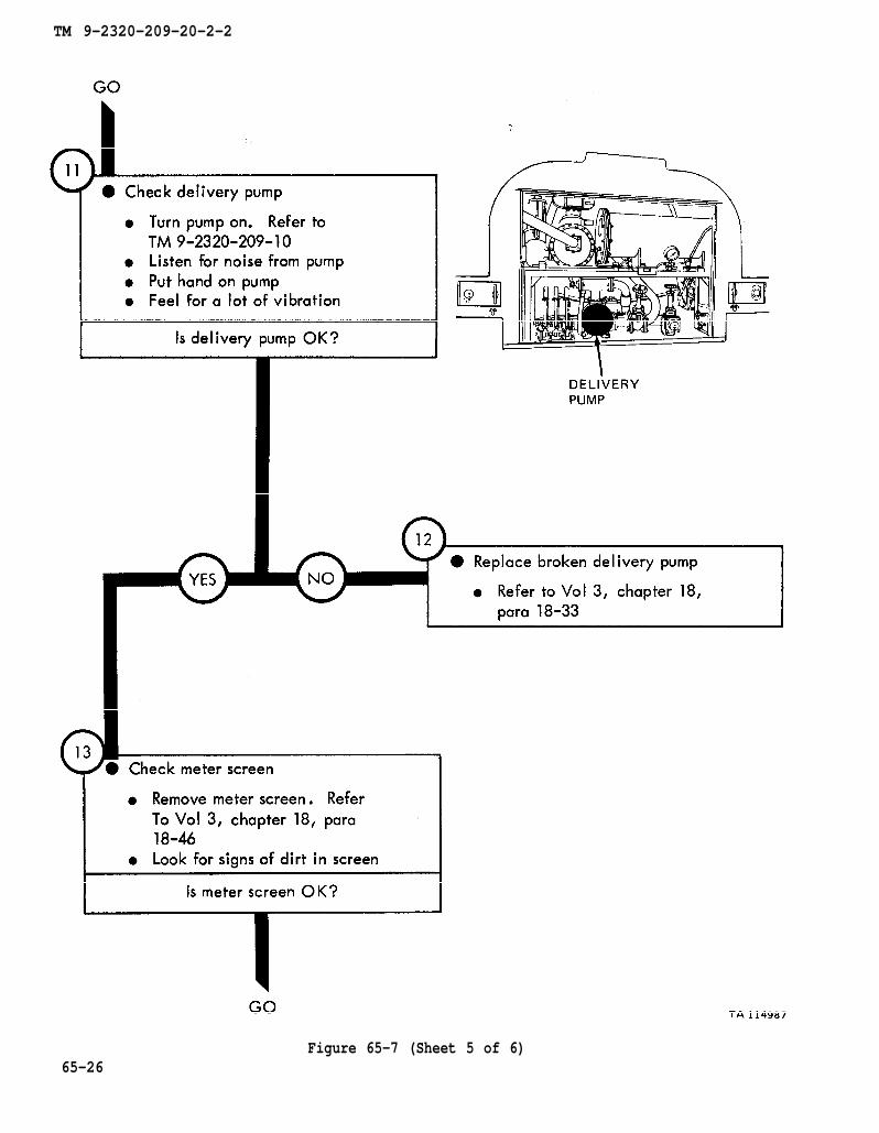
Figure 65-7 (Sheet 5 of 6)65-26
chapter 18
para 18-46
chapter 18
para 18-46
TM 9-2320-209-20-2-2
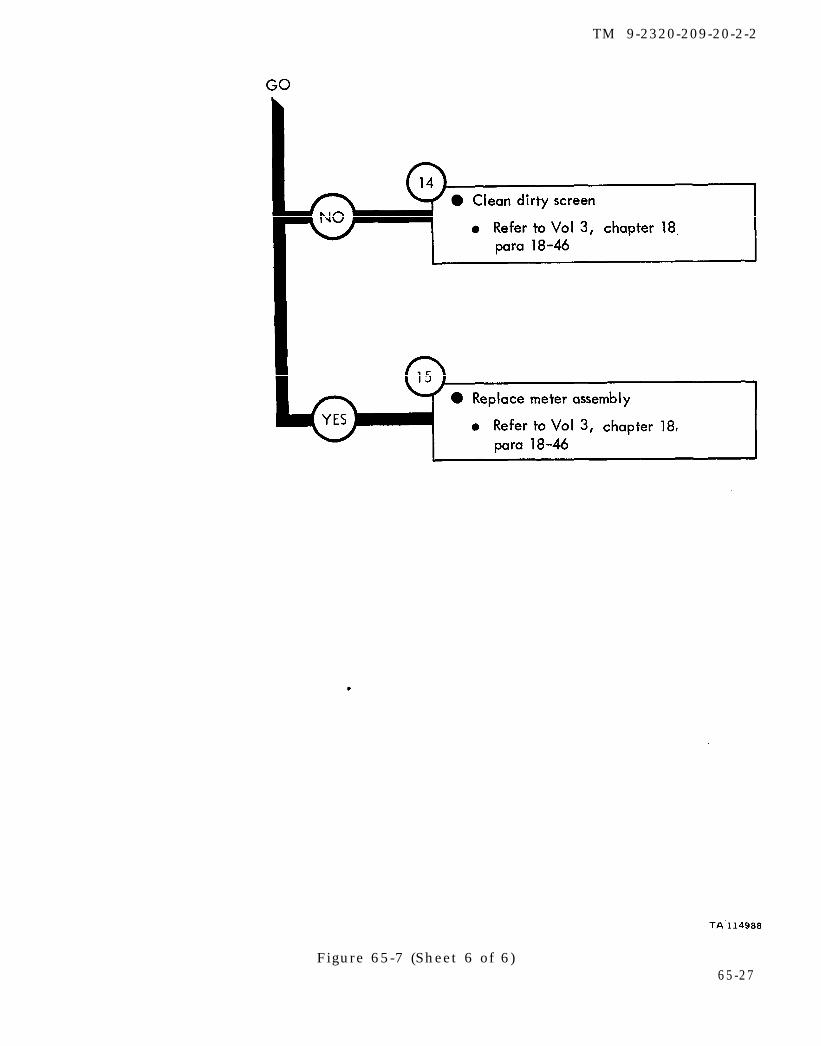
Figure 65-7 (Sheet 6 of 6)65-27

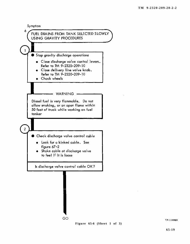
TM 9-2320-209-20-2-2
CHAPTER 66FUEL TANK BODY (TRUCK M49A1C)TROUBLESHOOTING SUMMARY
66-1. GENERAL. This chapter gives a summary of troubleshooting procedures givenin chapter 65 for the fuel tank body (M49A1C).
66-2. PROCEDURES. The summary in this chapter covers all fault symptoms foundin the detailed troubleshooting procedures. Chapter 7 outlines a sample troubleshoot-ing procedure. The summary procedures are based on the “what-to-do” portions ofthe detailed procedures and do not include the “how -to–do–it” instructions. Warn-ings, cautions, and notes are given where needed.
66-1
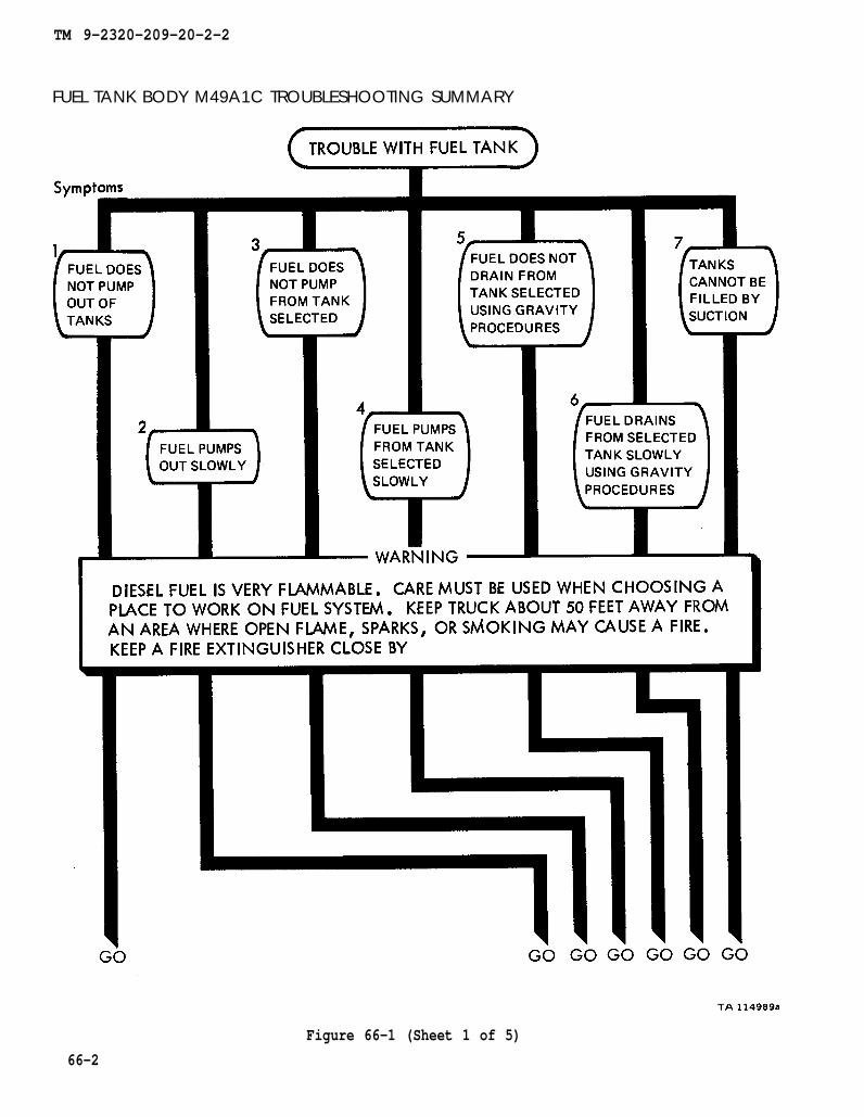
TM 9-2320-209-20-2-2
FUEL TANK BODY M49A1C TROUBLESHOOTING SUMMARY
Figure 66-1 (Sheet 1 of 5)
66-2

TM 9-2320-209-20-2-2
Figure 66-1 (Sheet 2 of 5)66-3
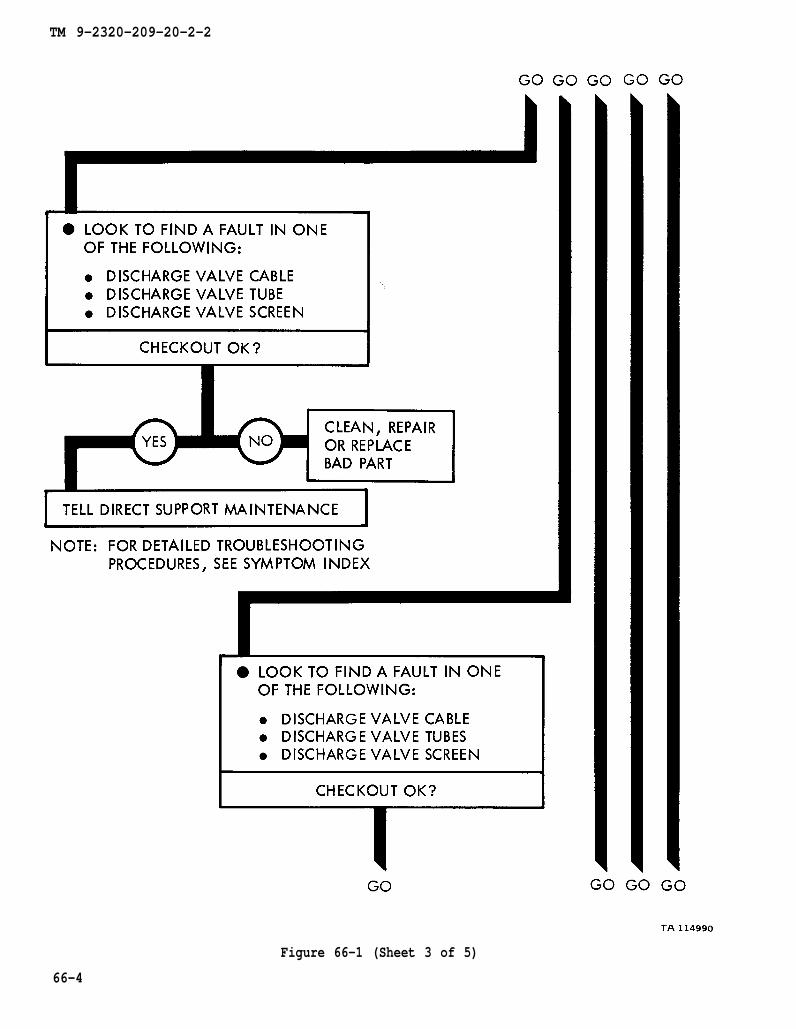
TM 9-2320-209-20-2-2
66-4
Figure 66-1 (Sheet 3 of 5)
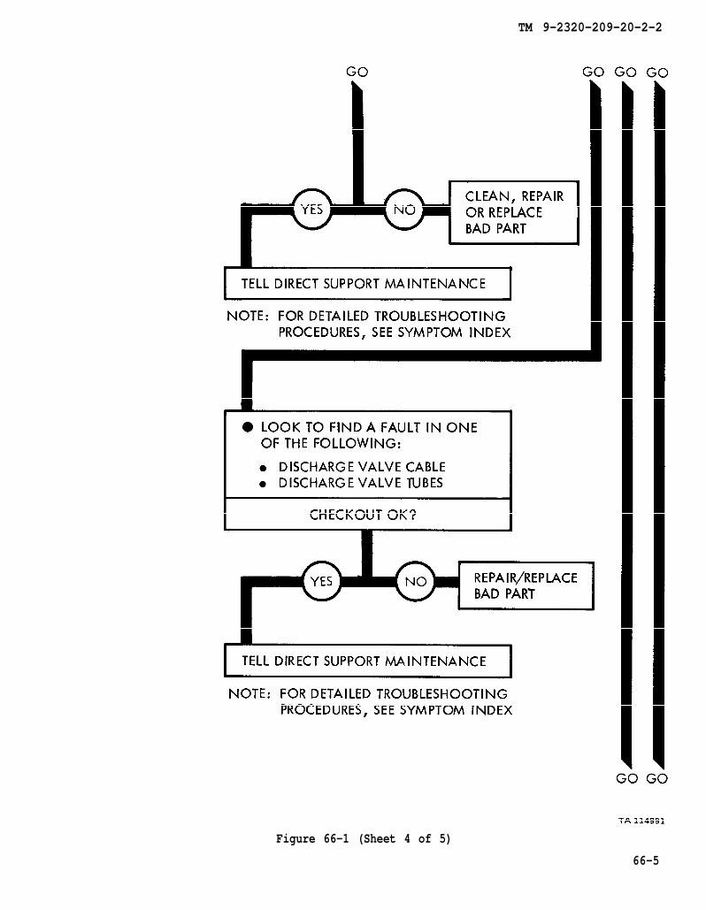
TM 9-2320-209-20-2-2
Figure 66-1 (Sheet 4 of 5)
66-5
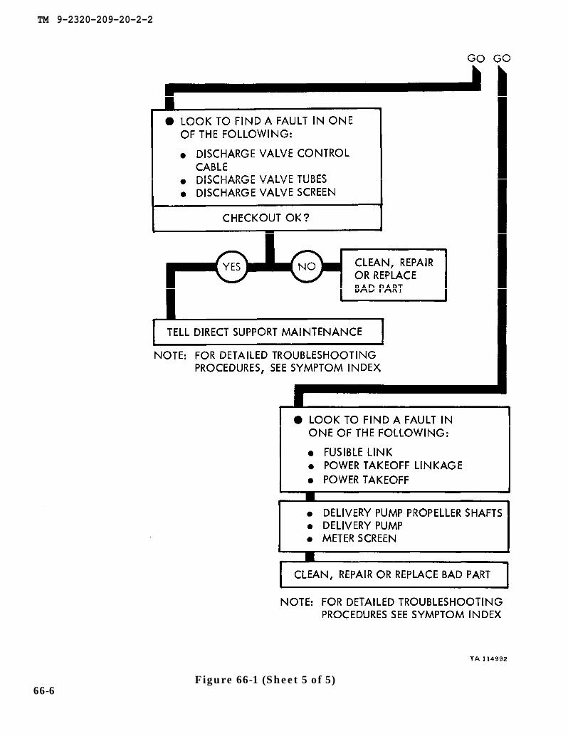
TM 9-2320-209-20-2-2
Figure 66-1 (Sheet 5 of 5)66-6

TM 9-2320-209-20-2-2
CHAPTER 67
FUEL TANK BODY (TRUCK M49A1C) SUPPORT DIAGRAMS
67-1. GENERAL. This chapter gives the diagrams you need when doing trouble-shooting procedures in chapterdiagrams used in this manual.
65. Table 3-1 is a complete listing of all support
67-1

TM 9-2320-209-20-2-2
Figure 67-1. Fuel Tank Body (M49A1C) Support Diagram
67-2
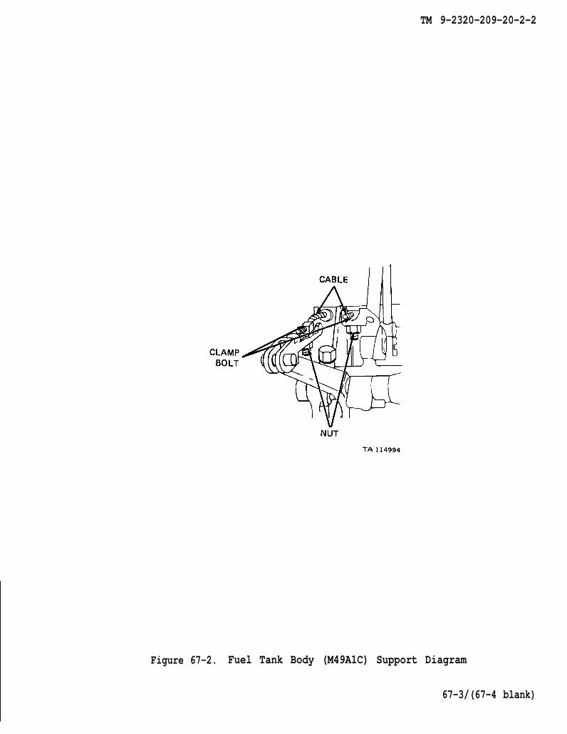
TM 9-2320-209-20-2-2
Figure 67-2. Fuel Tank Body (M49A1C) Support Diagram
67-3/(67-4 blank)


TM 9-2320-209-20-2-2
CHAPTER 68
FUEL TANK BODY (TRUCK M49A1C) CHECKOUT PROCEDURES
68-1. GENERAL. This chapter gives procedures for checking out the system aftertroubleshooting and repair have been done. Proceduresshowing the checkout steps in order and refering to thesystem does not checkout.
are set up in flow chart formfault symptom index when the
68-1
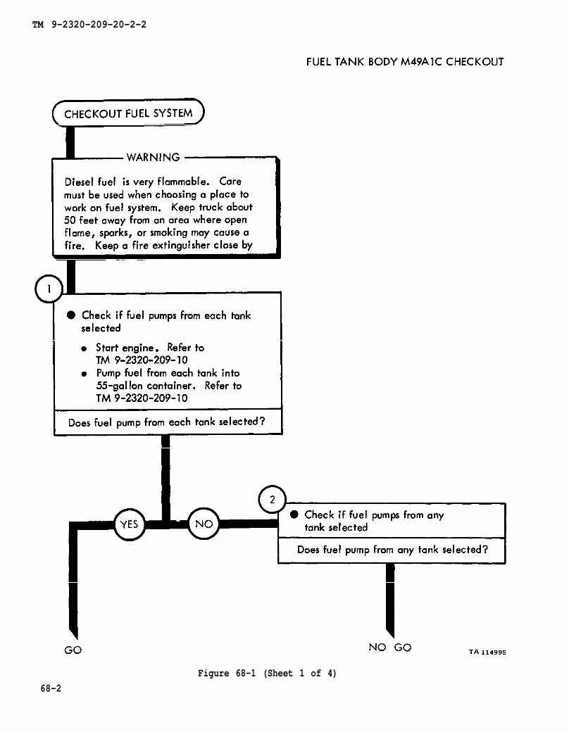
TM 9-2320-209-10
TM 9-2320-209-10
TM 9-2320-209-20-2-2
Figure 68-1 (Sheet 1 of 4)
68-2
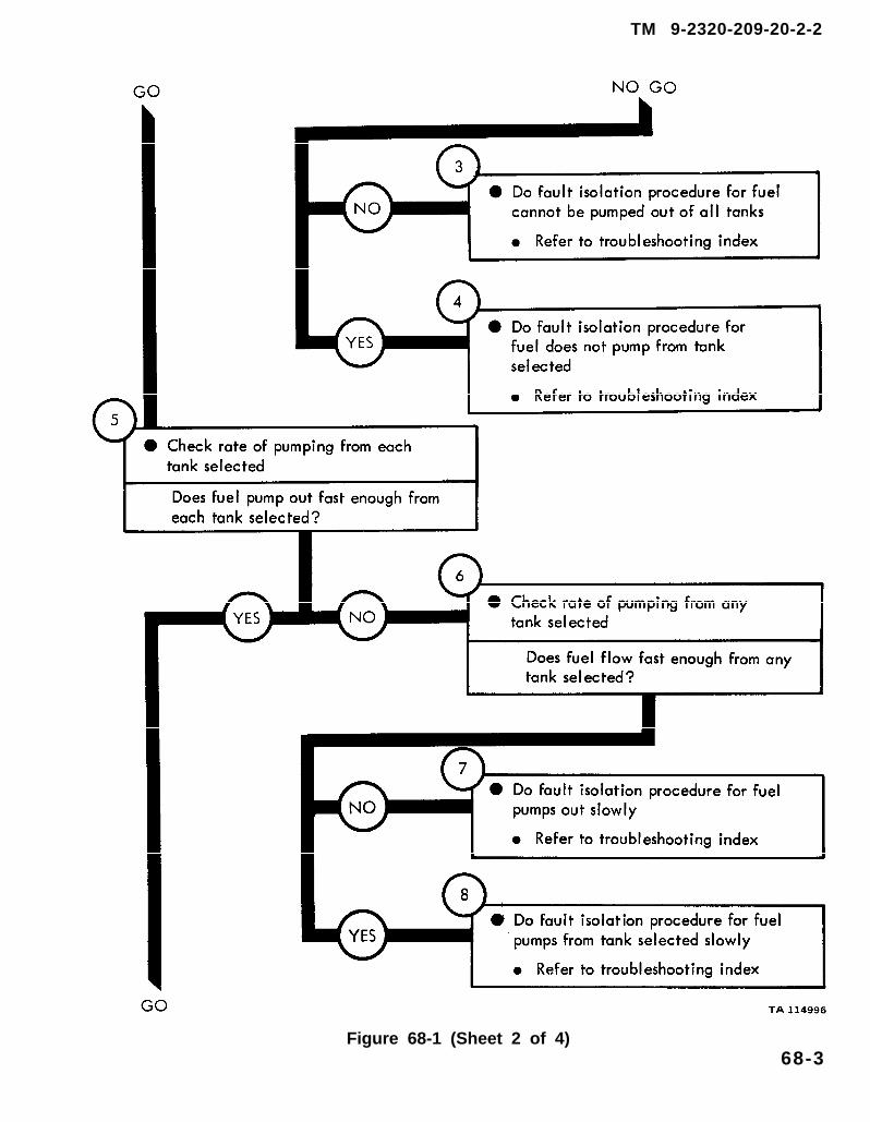
TM 9-2320-209-20-2-2
Figure 68-1 (Sheet 2 of 4)68-3
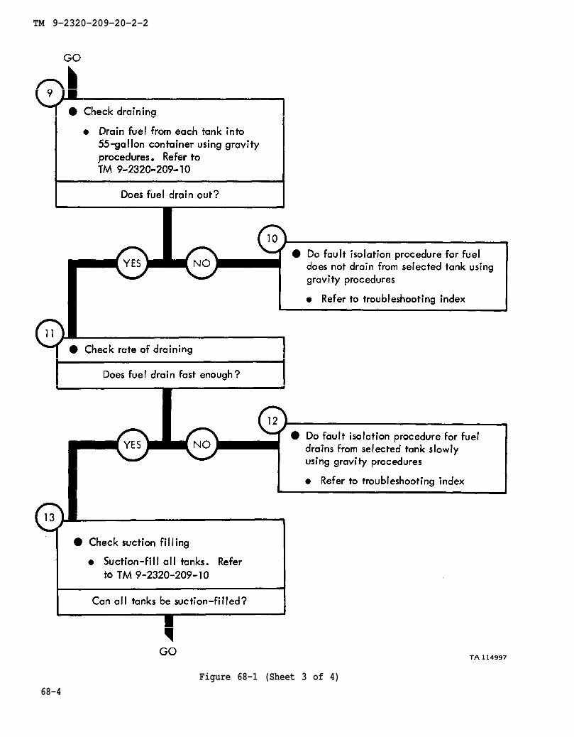
TM 9-2320-209-10
TM 9-2320-209-10
TM 9-2320-209-20-2-2
Figure 68-1 (Sheet 3 of 4)
68-4

TM 9-2320-209-10
TM 9-2320-209-20-2-2
Figure 68-1 (Sheet 4 of 4)68-5/ (68-6 blank)

TM 9-2320-209-20-2-2
CHAPTER 69
FUEL TANK BODY (TRUCK M49A2C) TROUBLESHOOTING
69-1. EQUIPMENT ITEMS COVERED. This chapter gives equipment troubleshootingprocedures for the fuel tank body M49A2C, for which there are authorized correctivemaintenance tasks at the organizational maintenance level.
69-2. EQUIPMENT ITEMS NOT COVERED. All equipment items for which correctivemaintenance is authorized at the organizational maintenance level are covered in thischapter.
69-1
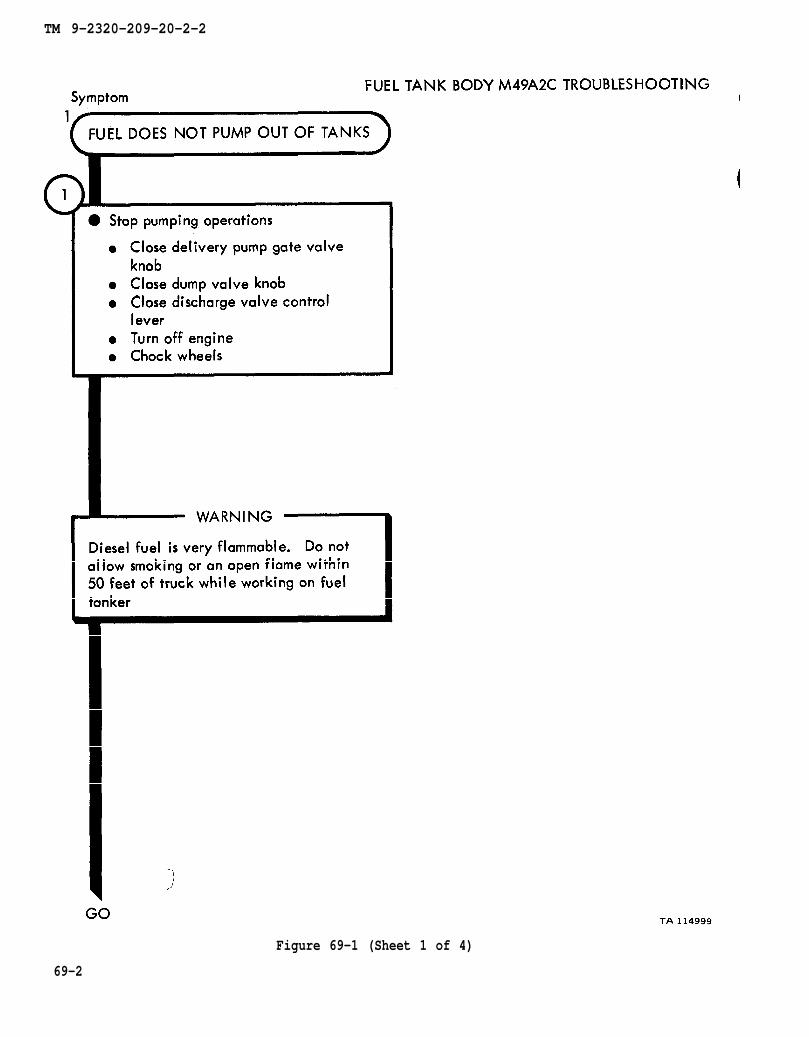
TM 9-2320-209-20-2-2
69-2
Figure 69-1 (Sheet 1 of 4)
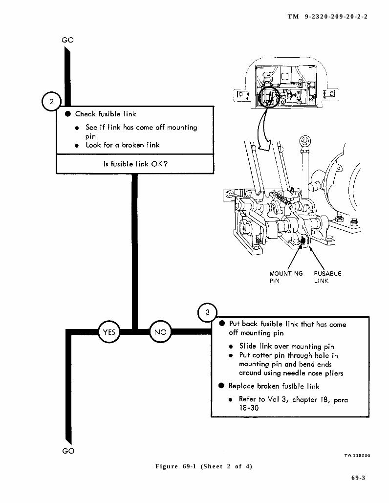
chapter 18 para 18-30
TM 9-2320-209-20-2-2
Figure 69-1 (Sheet 2 of 4)
69-3
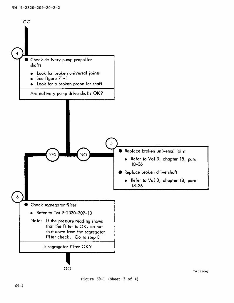
figure 71-1
chapter 18
chapter 18
para 18-36
para 18-36
TM 9-2320-209-10
TM 9-2320-209-20-2-2
Figure 69-1 (Sheet 3 of 4)
69-4

chapter 18
para 18-40
TM 9-2320-209-10
chapter 18 para 18-34
chapter 18 para 18-33
chapter 18
para 18-47
TM 9-2320-209-20-2-2
Figure 69-1 (Sheet 4 of 4)69-5
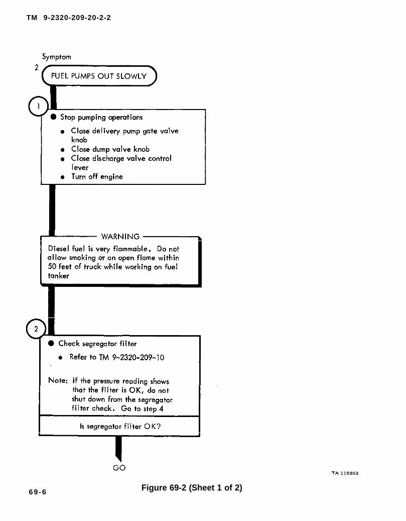
TM 9-2320-209-10
TM 9-2320-209-20-2-2
Figure 69-2 (Sheet 1 of 2)69-6
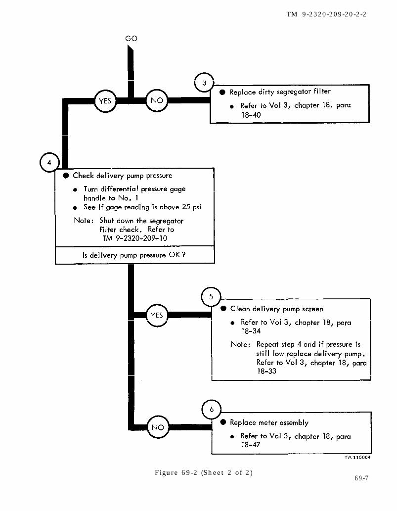
chapter 18 para 18-40
TM 9-2320-209-10
chapter 18 para 18-34
chapter 18 para 18-33
chapter 18 para 18-47
TM 9-2320-209-20-2-2
Figure 69-2 (Sheet 2 of 2)69-7
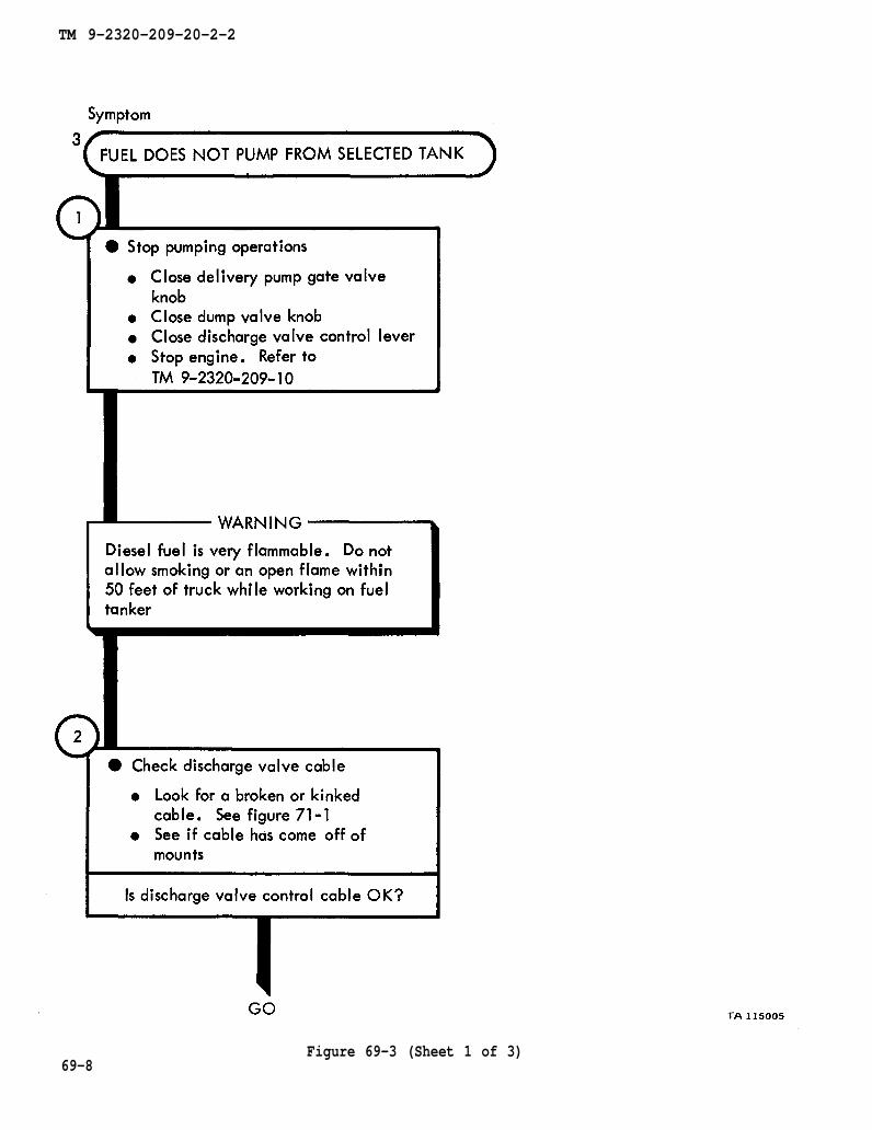
TM 9-2320-209-10
figure 71-1
TM 9-2320-209-20-2-2
69-8Figure 69-3 (Sheet 1 of 3)
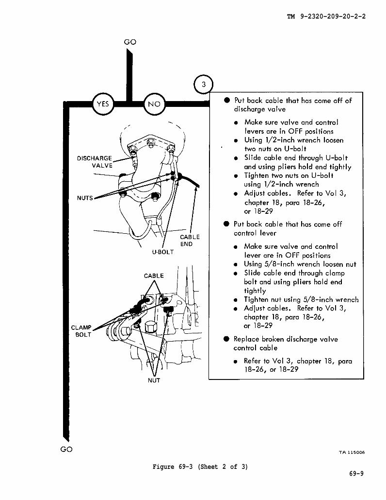
chapter 18 para 18-26
para 18-26 chapter 18
para 18-26 chapter 18
TM 9-2320-209-20-2-2
Figure 69-3 (Sheet 2 of 3)69-9

chapter 18
para 18-21
para 18-19
chapter 18
TM 9-2320-209-20-2-2
Figure 69-3 (Sheet 3 of 3)69-10
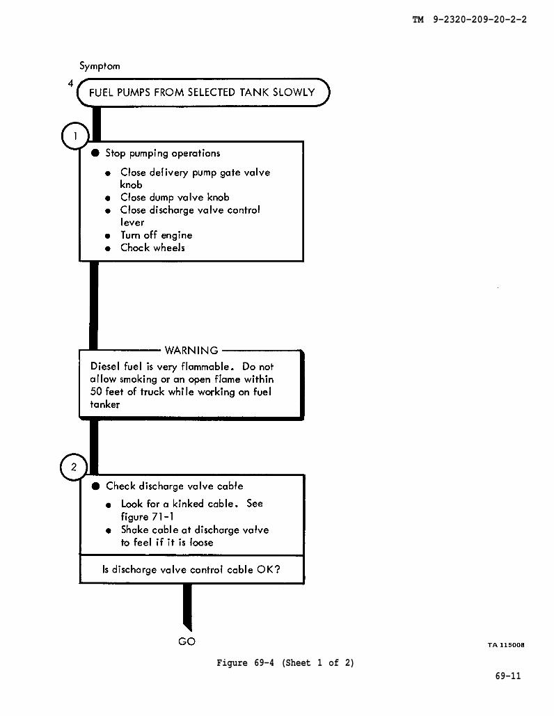
figure 71-1
TM 9-2320-209-20-2-2
Figure 69-4 (Sheet 1 of 2)69-11

chapter 18
chapter 18
para 18-26
para 18-26
chapter 18 para 18-21
TM 9-2320-209-20-2-2
Figure 69-4 (Sheet 2 of 2)69-12

TM 9-2320-209-10
figure 71-1
TM 9-2320-209-20-2-2
Figure 69-5 (Sheet 1 of 3)69-13

Vol 3
chapter 18 para 18-26
chapter 18 para 18-26
chapter 18
para 18-21
TM 9-2320-209-20-2-2
Figure 69-5 (Sheet 2 of 3)
69-14

chapter 18 para 18-19
TM 9-2320-209-20-2-2
Figure 69-5 (Sheet 3 of 3)
69-15

TM 9-2320-209-10
TM 9-2320-209-10
figure 71-1
TM 9-2320-209-20-2-2
Figure 69-6 (Sheet 1 of 2)69-16
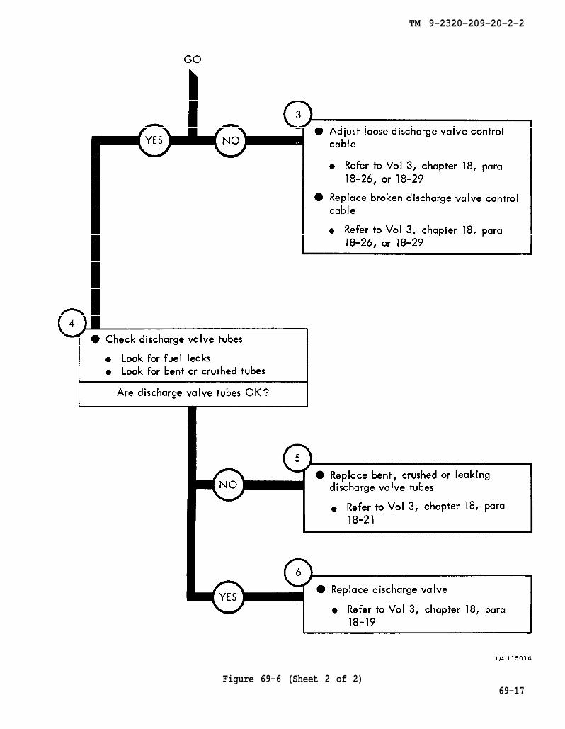
chapter 18
chapter 18
para 18-26
para 18-26
chapter 18 para 18-21
chapter 18 para 18-19
TM 9-2320-209-20-2-2
Figure 69-6 (Sheet 2 of 2)69-17

TM 9-2320-209-10
TM 9-2320-209-20-2-2
69-18Figure 69-7 (Sheet 1 of 3)

chapter 18
para 18-36
chapter 18
para 18-36
TM 9-2320-209-10
chapter 18 para 18-40
TM 9-2320-209-20-2-2
Figure 69-7 (Sheet 2 of 3)6 9 - 1 9

TM 9-2320-209-10
chapter 18 para 18-34
chapter 18 para 18-33
chapter 18
para 18-46
TM 9-2320-209-20-2-2
69-20Figure 69-7 (Sheet 3 of 3)
TM 9-2320-209-20-2-2
CHAPTER 70
FUEL TANK BODY (TRUCK M49A2C)TROUBLESHOOTING SUMMARY
70-1. GENERAL. This chapter gives a summary of troubleshooting procedures givenin chapter 69 for the fuel tank body (M49A2C).
70-2. PROCEDURES. The summary in this chapter covers all fault symptoms foundin the detailed troubleshooting procedures. Chapter 7 outlines a sample troubleshoot-ing procedure. The summary procedures are based on the “what-to-do” portions ofthe detailed procedures and do not include the “how-to-do-it” instructions. Warn–ings, cautions, and notes are given where needed.
70-1
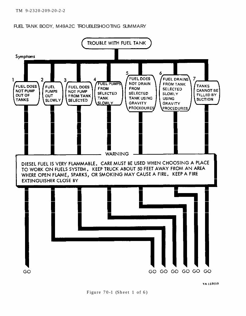
TM 9-2320-209-20-2-2
FUEL TANK BODY, M49A2C TROUBLESHOOTING SUMMARY
Figure 70-1 (Sheet 1 of 6)

TM 9-2320-209-20-2-2
Figure 70-1 (Sheet 2 of 6)70-3
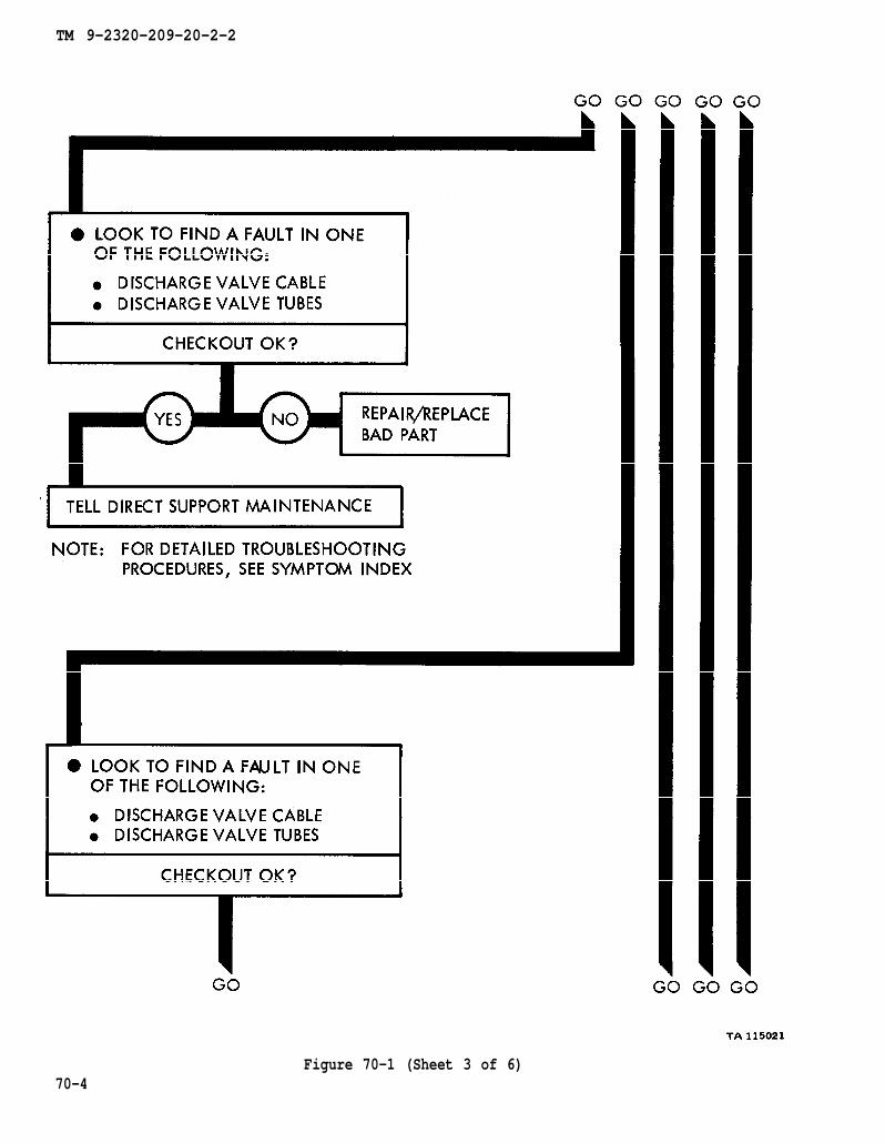
TM 9-2320-209-20-2-2
Figure 70-1 (Sheet 3 of 6)70-4
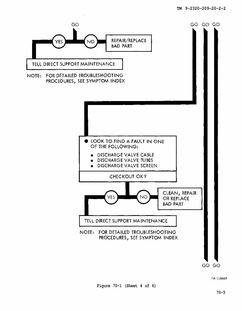
TM 9-2320-209-20-2-2
Figure 70-1 (Sheet 4 of 6)
70-5
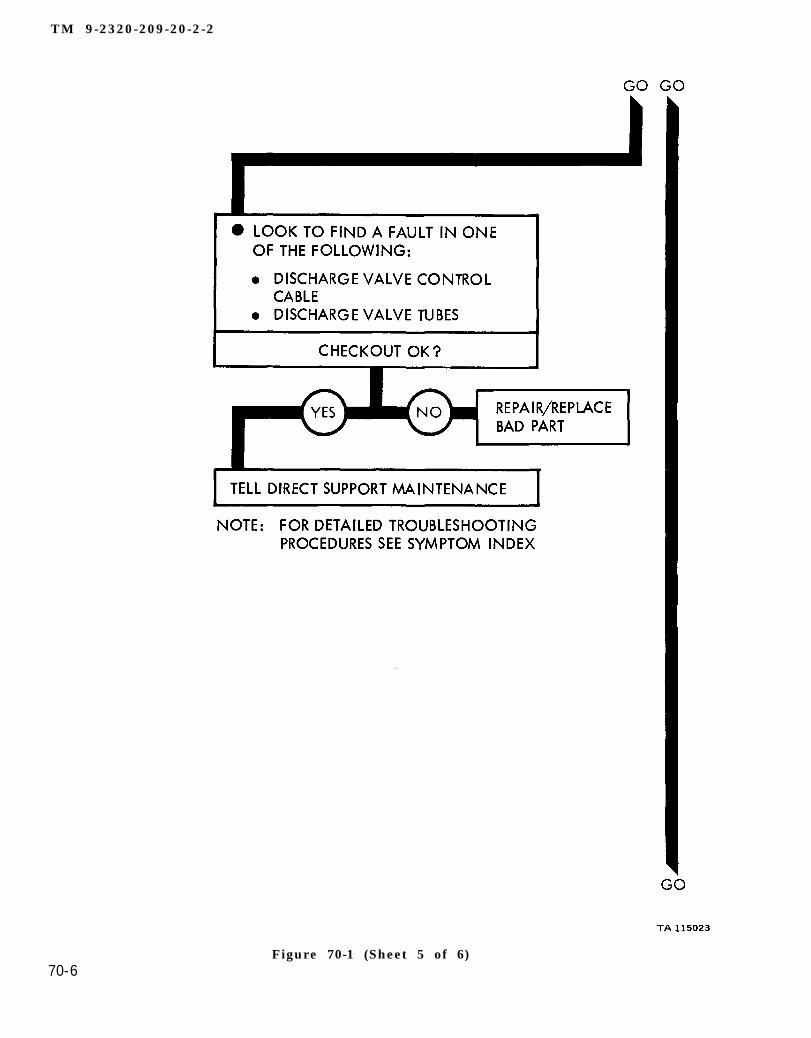
TM 9-2320-209-20-2-2
Figure 70-1 (Sheet 5 of 6)70-6

TM 9-2320-209-20-2-2
Figure 70-1 (Sheet 6 of 6)70-7/ (70-8 blank)

TM 9-2320-209-20-2-2
CHAPTER 71
FUEL TANK BODY (TRUCK M49A2C) SUPPORT DIAGRAMS
71-1. GENERAL. This chapter gives the diagrams you need when doing trouble-shooting procedures in chapter 69. Table 3-1 is a complete listing of all supportdiagrams used in this manual.
71-1
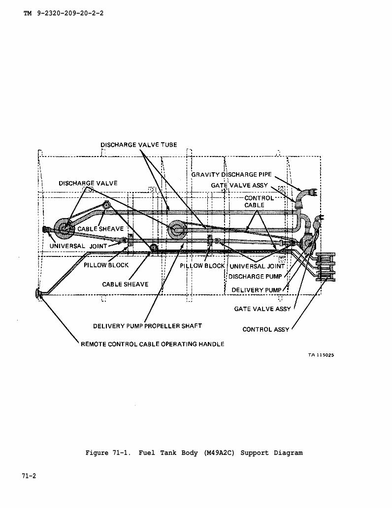
TM 9-2320-209-20-2-2
Figure 71-1. Fuel Tank Body (M49A2C) Support Diagram
71-2
TM 9-2320-209-20-2-2
CHAPTER 72
FUEL TANK BODY (TRUCK M49A2C) CHECKOUT PROCEDURES
72-1. GENERAL. This chapter gives procedures for checking out the system aftertroubleshooting and repair have been done. Procedures are set up in flow chart formshowing the checkout steps in order and referring to the fault symptom index when thesystem does not check out.
72-1

TM 9-2320-209-10
TM 9-2320-209-10
TM 9-2320-209-20-2-2
72-2
Figure 72-1 (Sheet 1 of 2)
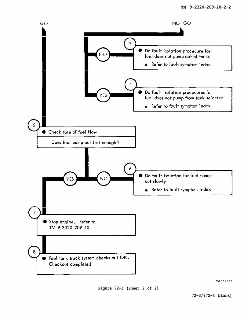
TM 9-2320-209-10
TM 9-2320-209-20-2-2
72-3/(72-4 blank)
Figure 72-1 (Sheet 2 of 2)

TM 9-2320-209-20-2-2
CHAPTER 73
EARTH BORING MACHINE TROUBLESHOOTING
73-1. EQUIPMENT ITEMS COVERED. This chapter gives equipment troubleshootingprocedures for the earth boring machine M764, for which there are authorized correc-tive maintenance tasks at the organizational maintenance level.
73-2. EQUIPMENT ITEMS NOT COVERED. All equipment items for which correctivemaintenance is authorized at the organizational maintenance level are covered in thischapter.
73-1

TM 9-2320-209-10
figure 75-1
chapter 10
chapter 10
para 10-4
para 10-4
TM 9-2320-209-20-2-2
73-2
Figure 73-1 (Sheet 1 of 2)

chapter 19
chapter 19
para 19-26
para 19-26
TM 9-2320-209-20-2-2
Figure 73-1 (Sheet 2 of 2)
73-3
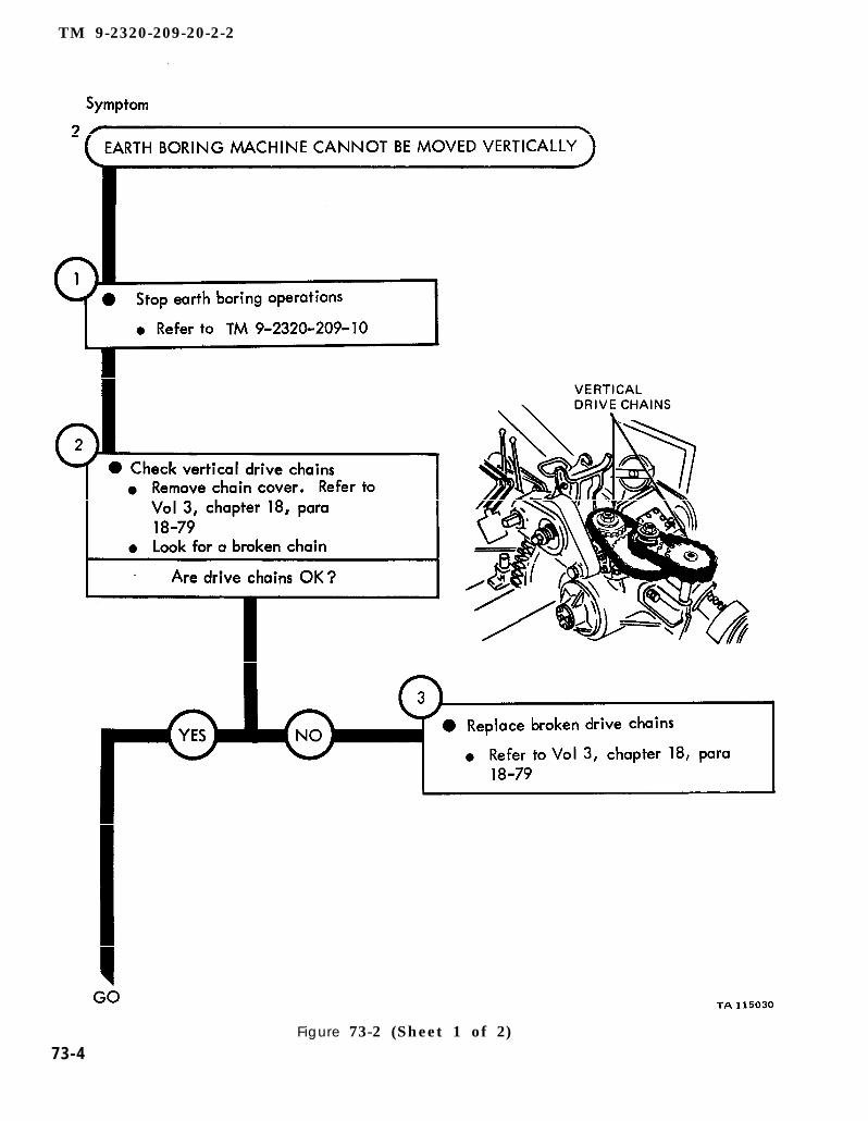
TM 9-2320-209-10
chapter 18 para 18-79
chapter 18 para 18-79
TM 9-2320-209-20-2-2
Figure 73-2 (Sheet 1 of 2)73-4
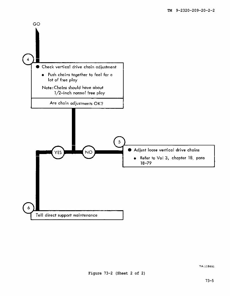
chapter 18 para 18-79
TM 9-2320-209-20-2-2
Figure 73-2 (Sheet 2 of 2)
73-5
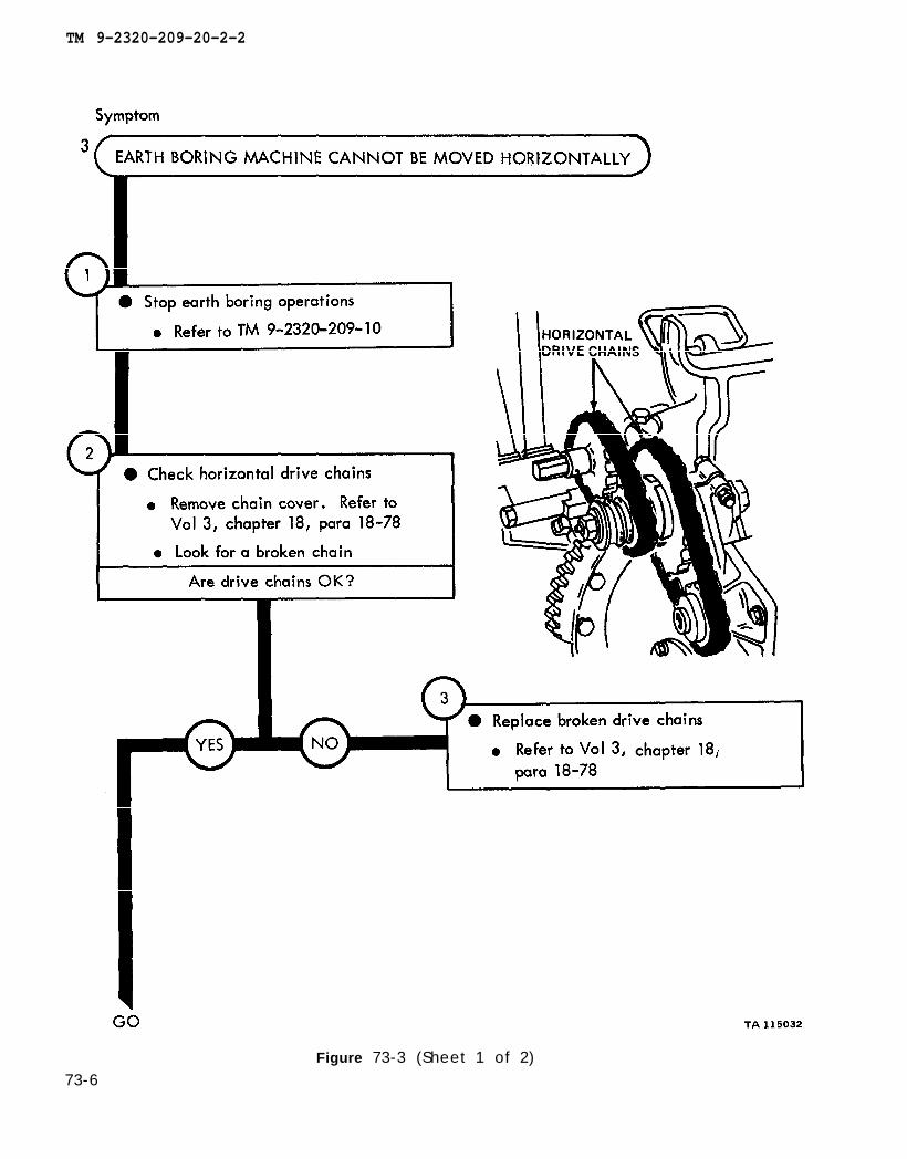
TM 9-2320-209-10
chapter 18 para 18-78
chapter 18
para 18-78
TM 9-2320-209-20-2-2
Figure 73-3 (Sheet 1 of 2)73-6

chapter 18 para 18-78
TM 9-2320-209-20-2-2
Figure 73-3 (Sheet 2 of 2)73-7
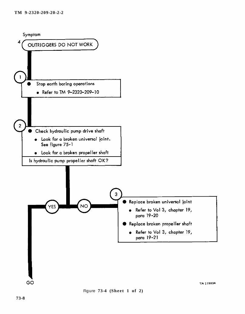
TM 9-2320-209-10
figure 75-1
chapter 19
para 19-20
para 19-21
chapter 19
TM 9-2320-209-20-2-2
73-8
Figure 73-4 (Sheet 1 of 2)
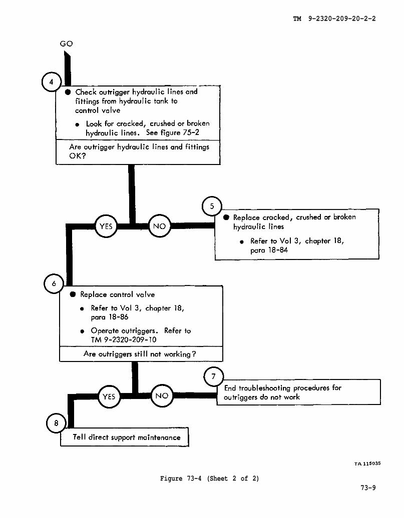
figure 75-2
chapter 18
para 18-84
chapter 18
para 18-86
TM 9-2320-209-10
TM 9-2320-209-20-2-2
Figure 73-4 (Sheet 2 of 2)73-9
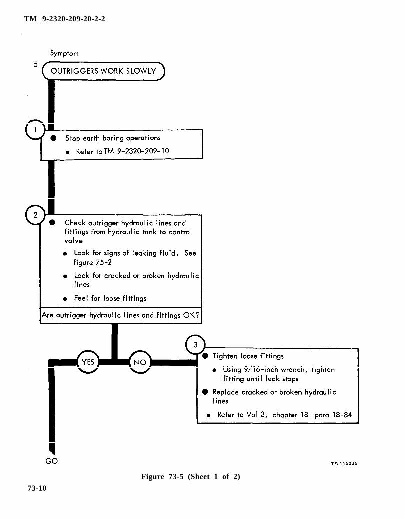
figure 75-2
TM 9-2320-209-10
chapter 18 para 18-84
TM 9-2320-209-20-2-2
73-10
Figure 73-5 (Sheet 1 of 2)

chapter 18 para 18-86
TM 9-2320-209-10
TM 9-2320-209-20-2-2
Figure 73-5 (Sheet 2 of 2)
73-11/(73-12 blank)


TM 9-2320-209-20-2-2
CHAPTER 74
EARTH BORING MACHINE TROUBLESHOOTING SUMMARY
74-1. GENERAL. This chapter gives a summary of troubleshooting procedures givenin chapter 73 for the earth boring machine (M764).
74-2. PROCEDURES. The summary in this chapter covers all fault symptoms foundin the detailed troubleshooting procedures. Chapter 7 outlines a sample troubleshoot-ing procedure. The summary procedures are based on the “what-to-do” portions ofthe detailed procedures and do not include the “how-to-do-it” instructions. Warn–ings, cautions, and notes are given where needed.
74-1
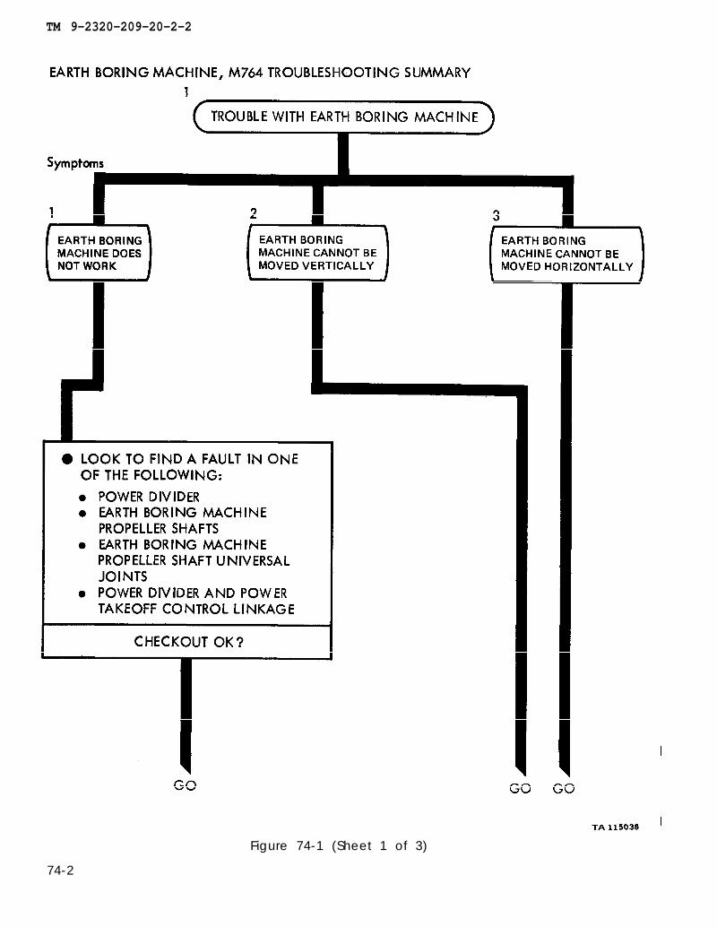
TM 9-2320-209-20-2-2
Figure 74-1 (Sheet 1 of 3)
74-2

TM 9-2320-209-20-2-2
Figure 74-1 (Sheet 2 of 3)
74-3
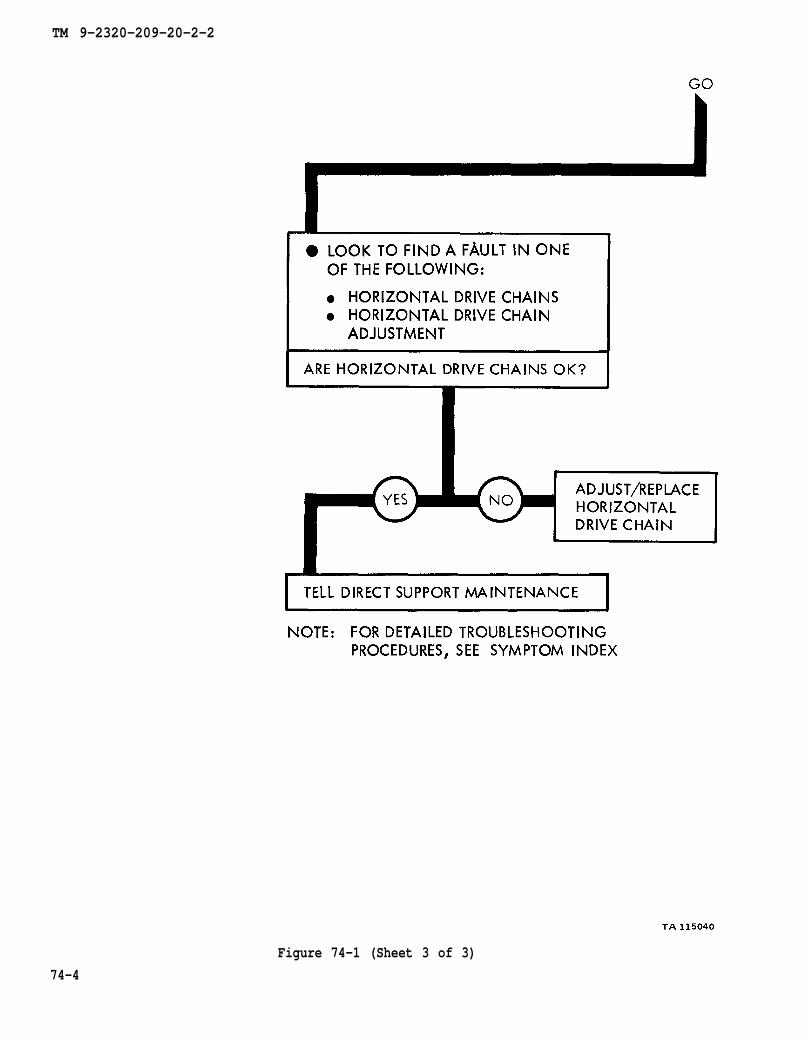
TM 9-2320-209-20-2-2
74-4
Figure 74-1 (Sheet 3 of 3)
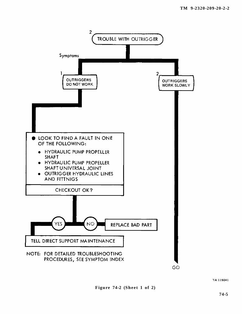
TM 9-2320-209-20-2-2
Figure 74-2 (Sheet 1 of 2)74-5
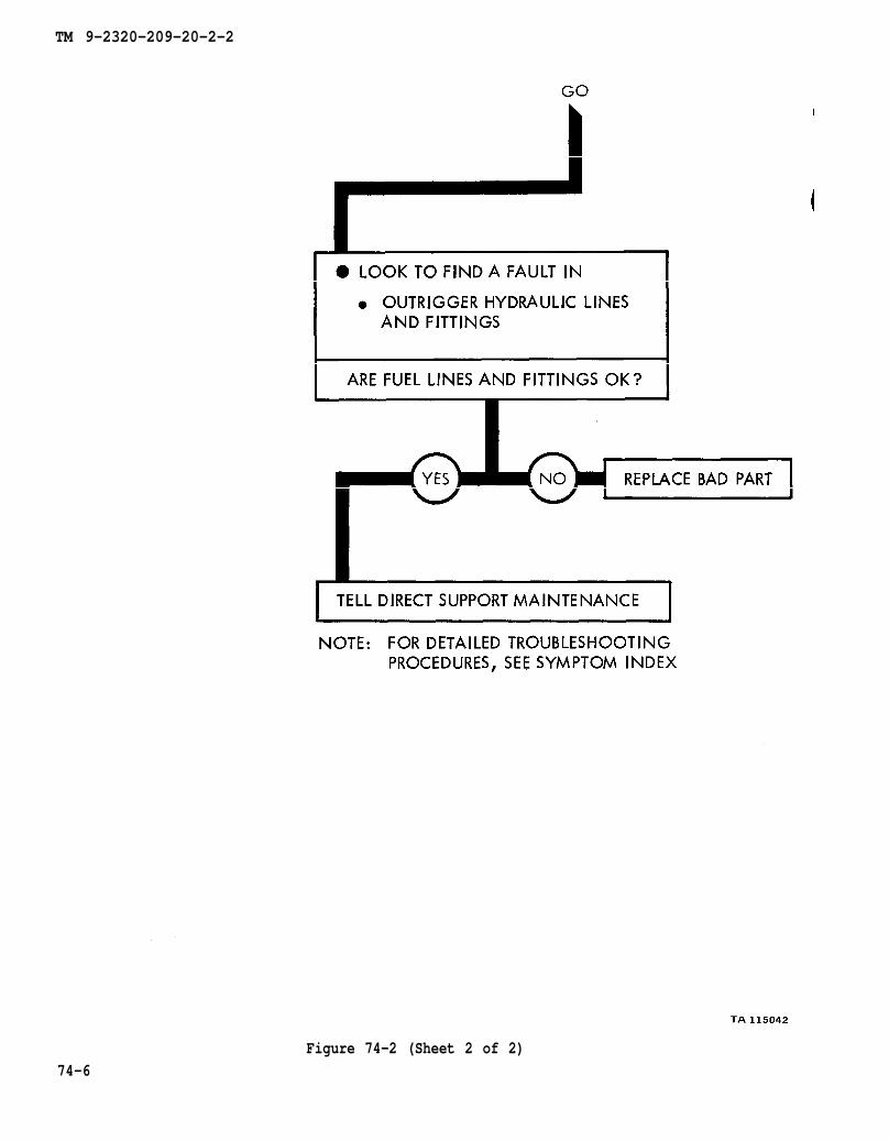
TM 9-2320-209-20-2-2
Figure 74-2 (Sheet 2 of 2)74-6

TM 9-2320-209-20-2-2
CHAPTER 75
EARTH BORING MACHINE SUPPORT DIAGRAMS
75-1. GENERAL. This chapter gives the diagrams you need when doing trouble-shooting procedures in chapter 73. Table 3-1 is a complete listing of all supportdiagrams used in this manual.
75-1
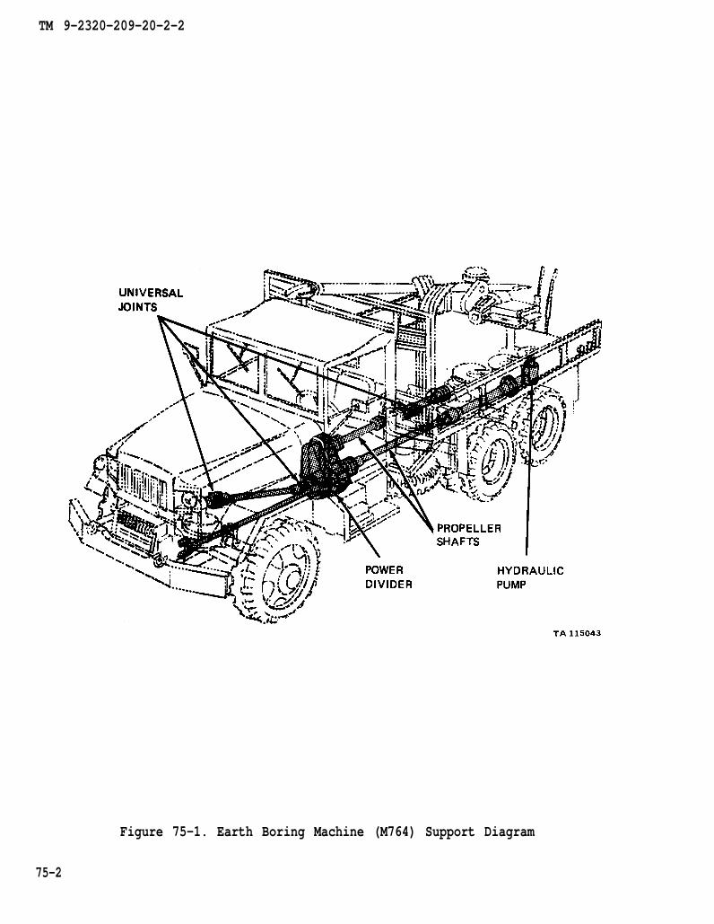
TM 9-2320-209-20-2-2
Figure 75-1. Earth Boring Machine (M764) Support Diagram
75-2
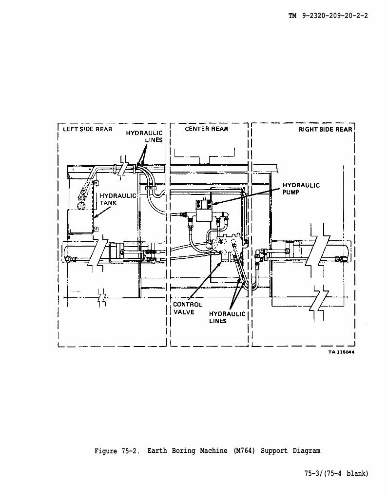
TM 9-2320-209-20-2-2
Figure 75-2. Earth Boring Machine (M764) Support Diagram
75-3/(75-4 blank)


TM 9-2320-209-20-2-2
CHAPTER 76
EARTH BORING MACHINE CHECKOUT PROCEDURES
76-1. GENERAL. This chapter gives procedures for checking out the system aftertroubleshooting and repair have been done. Procedures are set up in flow chart formshowing the checkout steps in order and referring to the fault symptom index whenthe system does not checkout.
76-1

TM 9-2320-209-10
TM 9-2320-209-10
TM 9-2320-209-20-2-2
Figure 76-1 (Sheet 1 of 3)
76-2
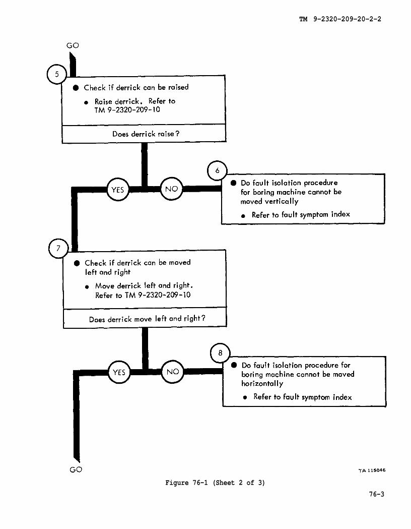
TM 9-2320-209-10
TM 9-2320-209-10
TM 9-2320-209-20-2-2
Figure 76-1 (Sheet 2 of 3)
76-3

TM 9-2320-209-10
TM 9-2320-209-10
TM 9-2320-209-10
TM 9-2320-209-10
TM 9-2320-209-10
TM 9-2320-209-10
TM 9-2320-209-20-2-2
Figure 76-1 (Sheet 3 of 3)
76-4
TM 9-2320-209-20-2-2
CHAPTER 77
FRONT WINCH TROUBLESHOOTING
77-1. EQUIPMENT ITEMS COVERED. This chapter gives equipment troubleshootingprocedures for the front winch, for which there are authorized corrective maintenancetasks at the organizational maintenance level.
77-2. EQUIPMENT ITEMS NOT COVERED. All equipment items for which correctivemaintenance is authorized at the organizational maintenance level are covered in thischapter.
77-1
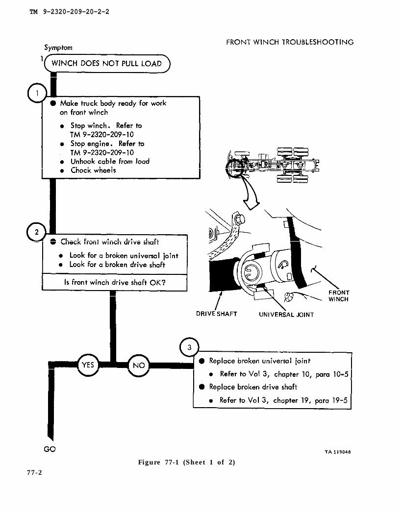
TM 9-2320-209-10
TM 9-2320-209-10
chapter 10
chapter 19
para 10-5
para 19-5
TM 9-2320-209-20-2-2
77-2Figure 77-1 (Sheet 1 of 2)
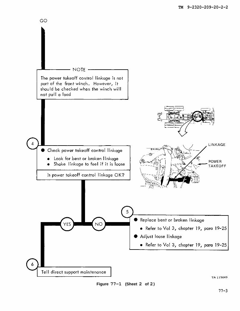
chapter 19
chapter 19
para 19-25
para 19-25
TM 9-2320-209-20-2-2
Figure 77-1 (Sheet 2 of 2)
77-3
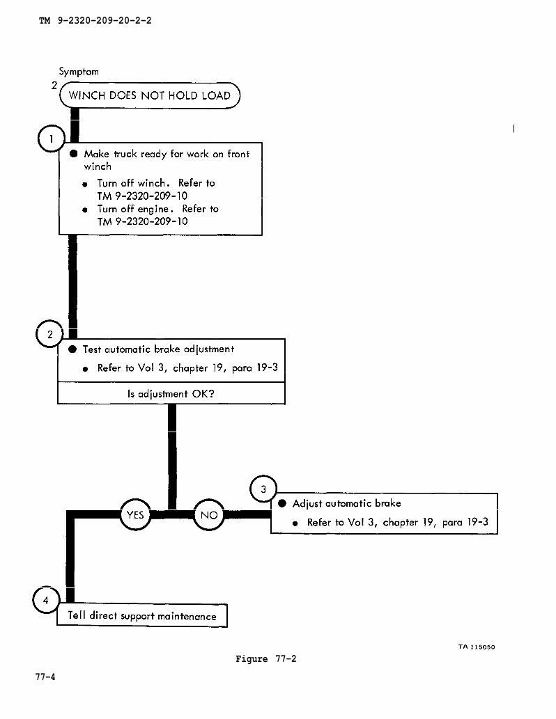
TM 9-2320-209-10
TM 9-2320-209-10
chapter 19 para 19-3
chapter 19 para 19-3
TM 9-2320-209-20-2-2
77-4
Figure 77-2

TM 9-2320-209-10
TM 9-2320-209-10
chapter 19 para 19-3
chapter 19 para 19-3
TM 9-2320-209-20-2-2
Figure 77-3
77-5/(77-6 blank)

TM 9-2320-209-20-2-2
CHAPTER 78
FRONT WINCH TROUBLESHOOTING SUMMARY
78-1. GENERAL. This chapter gives a summary of troubleshooting procedures givenin chapter 77 for the front winch.
78-2. PROCEDURES. The summary in this chapter covers all fault symptoms found inthe detailed troubleshooting procedures. Chapter 7 outlines a sample troubleshoot-ing procedure. The summary procedures are based on the “what-to-do” portions ofthe detailed procedures and do not include the “how-to-do-it” instructions. Warn-ings, cautions, and notes are given where needed.
78-1

TM 9-2320-209-20-2-2
FRONT WINCH TROUBLESHOOTING SUMMARY
Figure 78-1 (Sheet 1 of 2)
78-2

TM 9-2320-209-20-2-2
Figure 78-1 (Sheet 2 of 2)
78-3/(78-4 blank)


TM 9-2320-209-20-2-2
CHAPTER 79
FRONT WINCH CHECKOUT PROCEDURES
79-1. GENERAL. This chapter gives procedures for checking out the system aftertroubleshooting and repair have been done. Procedures are set up in flow chart formshowing the checkout steps in order and referring to the fault symptom index whenthe system does not check out.
79-1
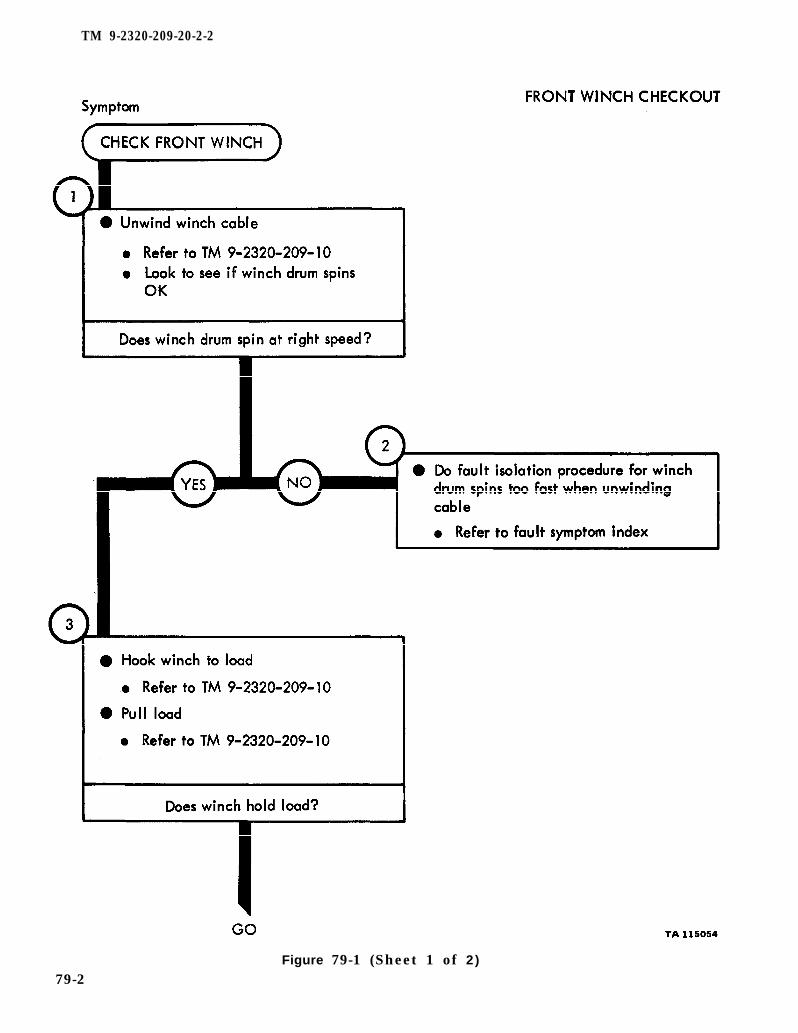
TM 9-2320-209-10
TM 9-2320-209-10
TM 9-2320-209-10
TM 9-2320-209-20-2-2
Figure 79-1 (Sheet 1 of 2)
79-2

TM 9-2320-209-20-2-2
Figure 79-1 (Sheet 2 of 2)
79-3/(79-4 blank)

TM 9-2320-209-20-2-2
CHAPTER 80
EARTH BORING MACHINE REAR WINCH TROUBLESHOOTING
80-1. EQUIPMENT ITEMS COVERED. This chapter gives equipment troubleshootingprocedures for the earth boring machine rear winch, for which there are authorizedcorrective maintenance tasks at the organizational maintenance level.
80-2. EQUIPMENT ITEMS NOT COVERED. All equipment items for which correctivemaintenance is authorized at the organizational maintenance level are covered in thischapter.
80-1

TM 9-2320-209-10
TM 9-2320-209-10
TM 9-2320-209-10
TM 9-2320-209-20-2-2
Figure 80-1 (Sheet 1 of 4)
80-2

chapter 19 para 19-13
chapter 10
chapter 10
para 10-5
para 10-5
TM 9-2320-209-20-2-2
Figure 80-1 (Sheet 2 of 4)
80-3

chapter 19
chapter 19
para 19-2
para 19-2
TM 9-2320-209-20-2-2
Figure 80-1 (Sheet 3 of 4)
80-4
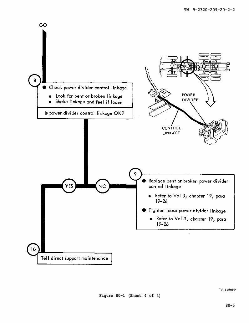
chapter 19
chapter 19
para 19-26
para 19-26
TM 9-2320-209-20-2-2
Figure 80-1 (Sheet 4 of 4)
80-5

Tm 9-2320-209-10
TM 9-2320-209-10
TM 9-2320-209-10
TM 9-2320-209-20-2-2
Figure 80-2 (Sheet 1 of 2)
80-6
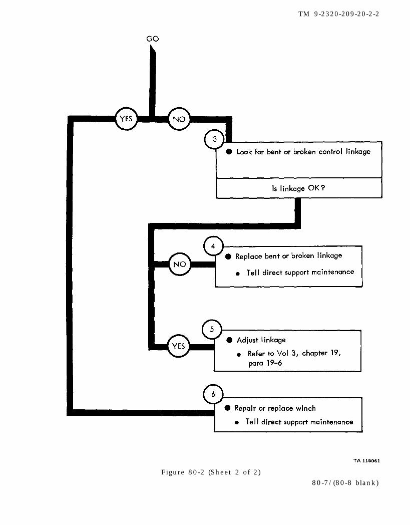
chapter 19
para 19-6
TM 9-2320-209-20-2-2
Figure 80-2 (Sheet 2 of 2)80-7/(80-8 blank)

TM 9-2320-209-20-2-2
CHAPTER 81PIPELINE CONSTRUCTION TRUCK REAR WINCH
TROUBLESHOOTING81-1. EQUIPMENT ITEMS COVERED. This chapter gives equipment troubleshootingprocedures for the pipeline construction truck rear winch, for which there areauthorized corrective maintenance tasks at the organizational maintenance level.
81-2. EQUIPMENT ITEMS NOT COVERED. All equipment items for which correctivemaintenance is authorized at the organizational maintenance level are covered in thischapter.
81-1
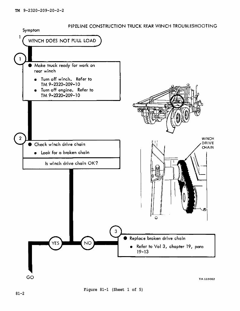
TM 9-2320-209-10
TM 9-2320-209-10
chapter 19 para 19-13
TM 9-2320-209-20-2-2
81-2Figure 81-1 (Sheet 1 of 5)

TM 9-2320-209-10
chapter 19 para 19-8
TM 9-2320-209-20-2-2
Figure 81-1 (Sheet 2 of 5)81-3

chapter 19 para 19-9
TM 9-2320-209-20-2-2
81-4Figure 81-1 (Sheet 3 of 5)
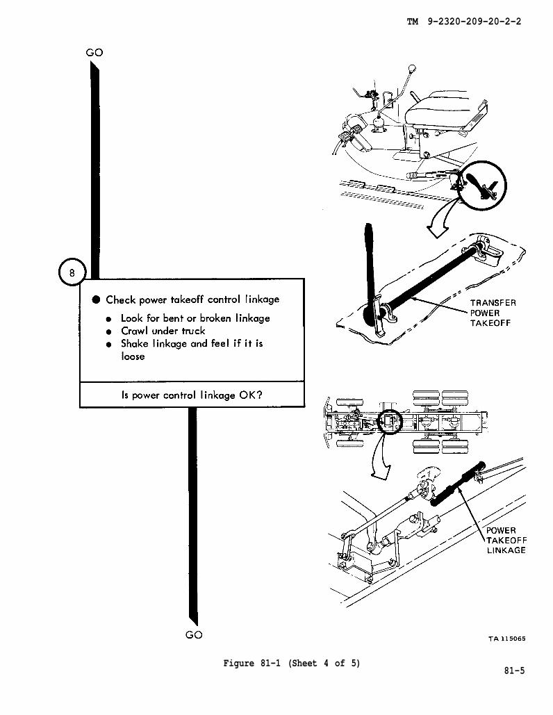
TM 9-2320-209-20-2-2
Figure 81-1 (Sheet 4 of 5)81-5

chapter 19
chapter 19
para 19-25
para 19-25
TM 9-2320-209-10
TM 9-2320-209-20-2-2
Figure 81-1 (Sheet 5 of 5)81-6

TM 9-2320-209-10
chapter 19 para 19-25
TM 9-2320-209-10
TM 9-2320-209-20-2-2
Figure 81-281-7/(81-8 blank)


TM 9-2320-209-20-2-2
CHAPTER 82
ENGINE COOLANT HEATER TROUBLESHOOTING
82-1. EQUIPMENT ITEMS COVERED. This chapter gives equipment troubleshootingprocedures for the engine coolant heater, for which there are authorized correctivemaintenance tasks at the organizational maintenance level.
82-2. EQUIPMENT ITEMS NOT COVERED. All equipment items for which correctivemaintenance is authorized at the organizational maintenance level are covered in thischapter.
82-1
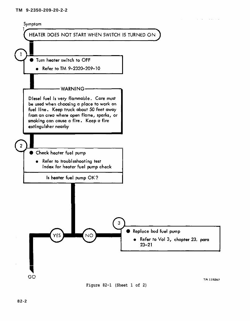
TM 9-2320-209-10
chapter 23 para 23-21
TM 9-2350-209-20-2-2
Figure 82-1 (Sheet 1 of 2)
82-2

TM 9-2320-209-20-2-2
Figure 82-1 (Sheet 2 of 2)
82-3
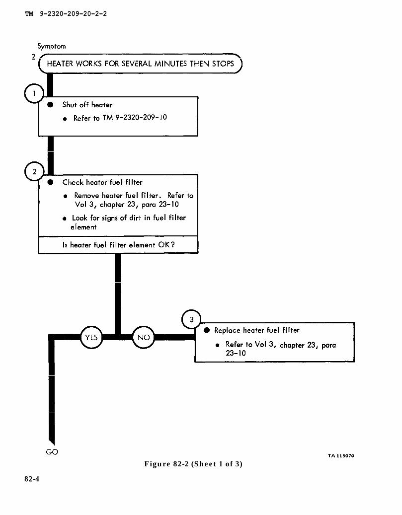
TM 9-2320-209-10
chapter 23 para 23-10
chapter 23 para 23-10
TM 9-2320-209-20-2-2
Figure 82-2 (Sheet 1 of 3)
82-4

chapter 23
para 23-10
chapter 4 para 4-5
chapter 23 para 23-21
TM 9-2320-209-20-2-2
Figure 82-2 (Sheet 2 of 3)
82-5

TM 9-2320-209-20-2-2
Figure 82-2 (Sheet 3 of 3)
82-6

figure84-1
chapter 4 para 4-5
TM 9-2320-209-10
TM 9-2320-209-20-2-2
Figure 82-3 (Sheet 1 of 3)
82-7
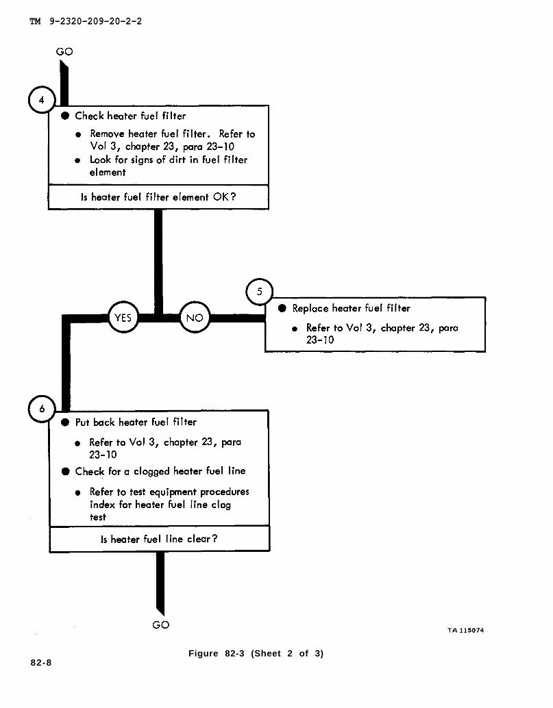
chapter 23 para 23-10
chapter 23 para 23-10
chapter 23 para 23-10
TM 9-2320-209-20-2-2
82-8Figure 82-3 (Sheet 2 of 3)
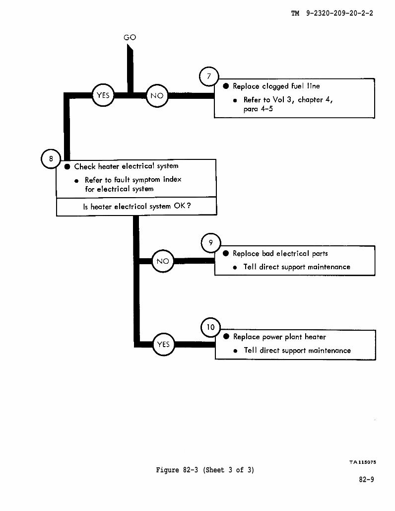
chapter 4
para 4-5
TM 9-2320-209-20-2-2
Figure 82-3 (Sheet 3 of 3)82-9
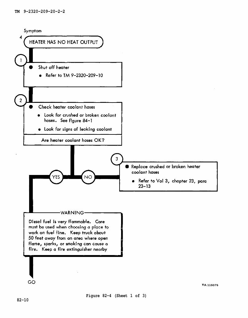
TM 9-2320-209-10
figure 84-1
chapter 23 para 23-13
TM 9-2320-209-20-2-2
82-10Figure 82-4 (Sheet 1 of 3)
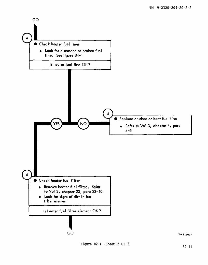
figure 84-1
chapter 4 para 4-5
chapter 23 para 23-10
TM 9-2320-209-20-2-2
82-11Figure 82-4 (Sheet 2 OI 3)
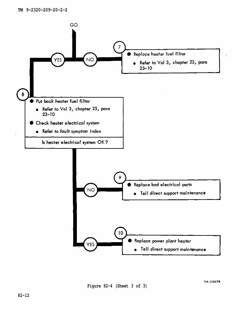
chapter 23 para 23-10
chapter 23 para 23-10
TM 9-2320-209-20-2-2
Figure 82-4 (Sheet 3 of 3)
82-12
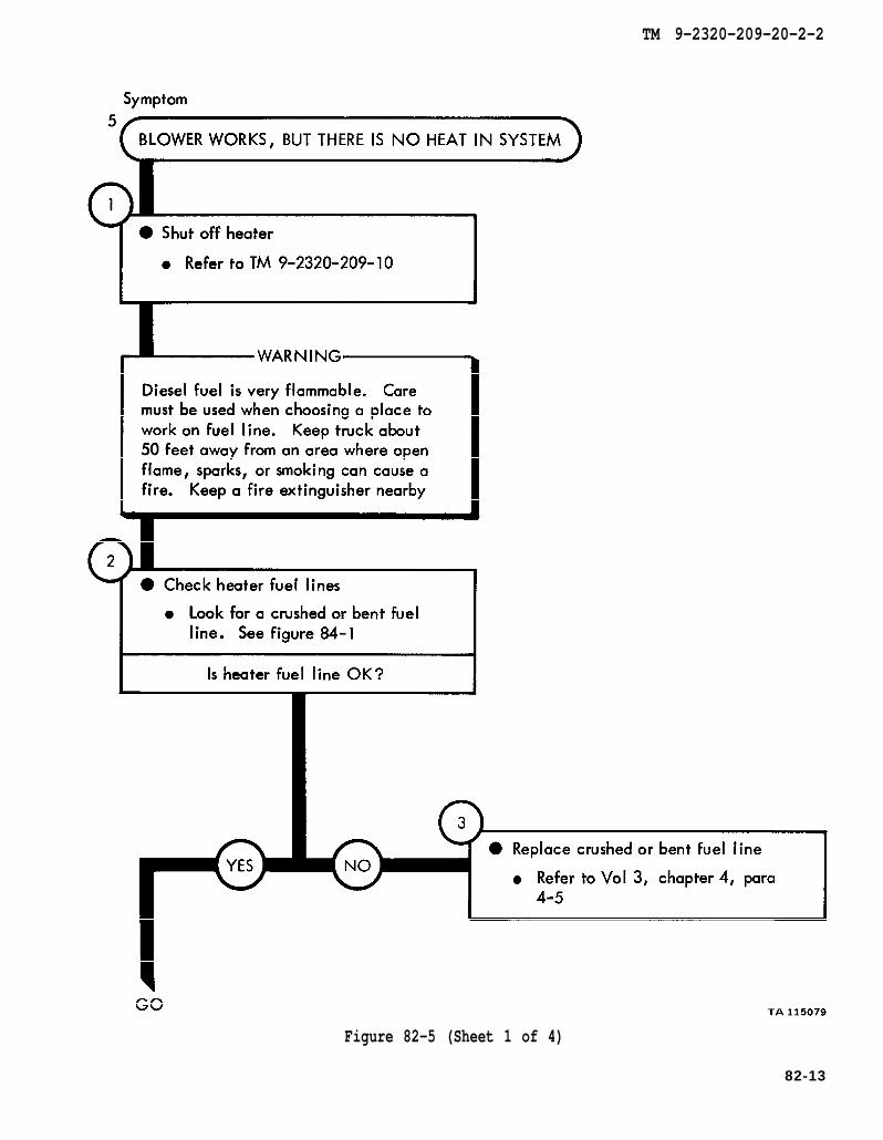
TM 9-2320-209-10
figure 84-1
chapter 4 para 4-5
TM 9-2320-209-20-2-2
Figure 82-5 (Sheet 1 of 4)
82-13

chapter 23 para 23-10
chapter 23 para 23-10
TM 9-2320-209-20-2-2
82-14Figure 82-5 (Sheet 2 of 4)
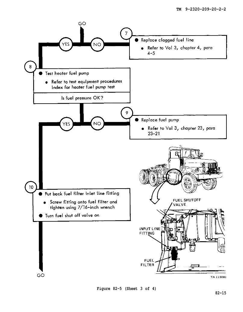
chapter 4 para 4-5
chapter 23 para 23-21
TM 9-2320-209-20-2-2
Figure 82-5 (Sheet 3 of 4)82-15

TM 9-2320-209-20-2
82-16Figure 82-5 (Sheet 4 of 4)
TM 9-2320-209-20-2-2
CHAPTER 83
ENGINE COOLANT HEATER TROUBLESHOOTING SUMMARY
83-1. GENERAL. This chapter gives a summary of troubleshooting procedures givenin chapter 82 for the engine coolant heater.
83-2. PROCEDURES. The summary in this chapter covers all fault symptoms foundin the detailed troubleshooting procedures. Chapter 7 outlines a sample troubleshoot-ing procedure. The summary procedures are based on the “what-to-do” portions ofthe detailed procedures and do not include the “how-to-do-it” instructions. Warn-ings, cautions, and notes are given where needed.
83-1

TM 9-2320-209-20-2-2
ENGINE COOLANT HEATER TROUBLESHOOTING SUMMARY
Figure 83-1 (Sheet 1 of 6)83-2

TM 9-2320-209-20-2-2
Figure 83-1 (Sheet 2 of 6)83-3
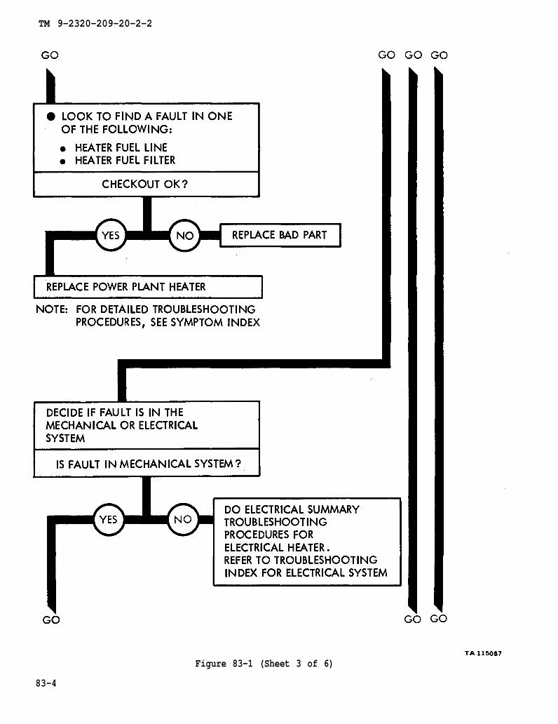
TM 9-2320-209-20-2-2
Figure 83-1 (Sheet 3 of 6)
83-4
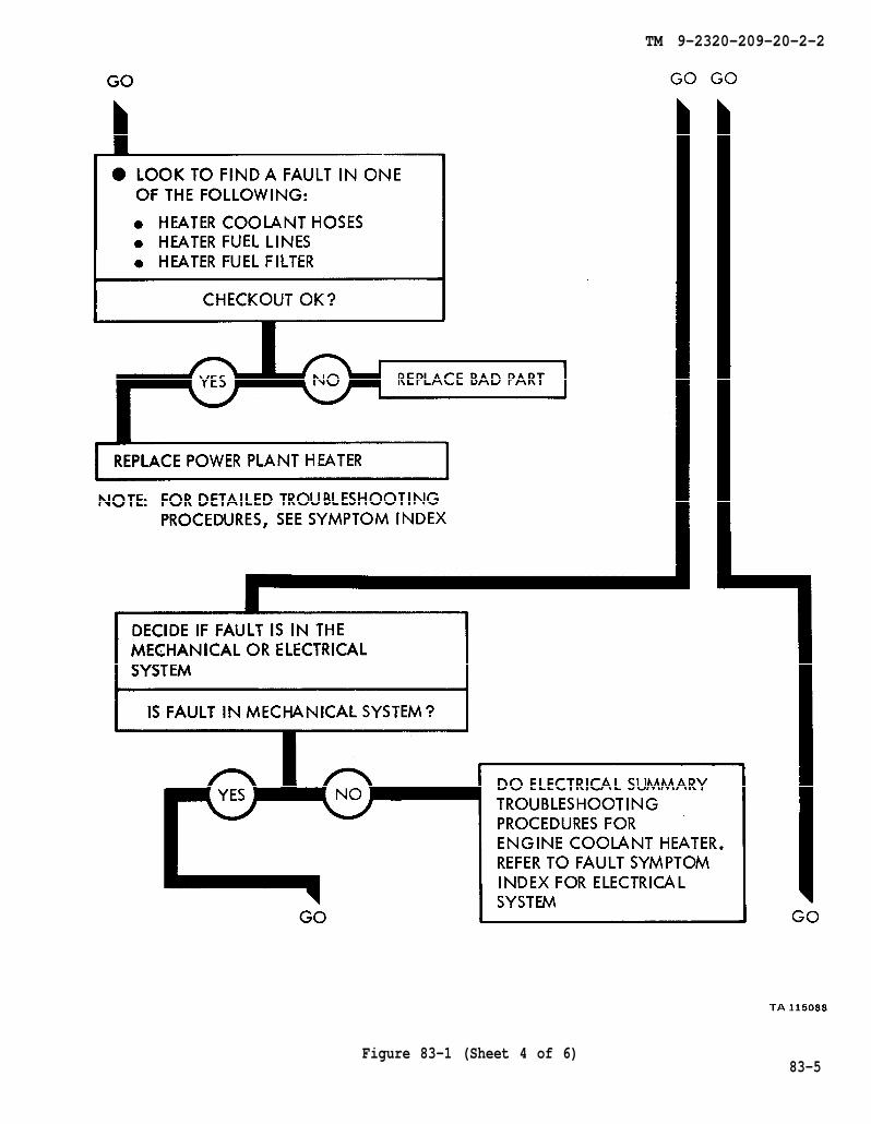
TM 9-2320-209-20-2-2
Figure 83-1 (Sheet 4 of 6)83-5
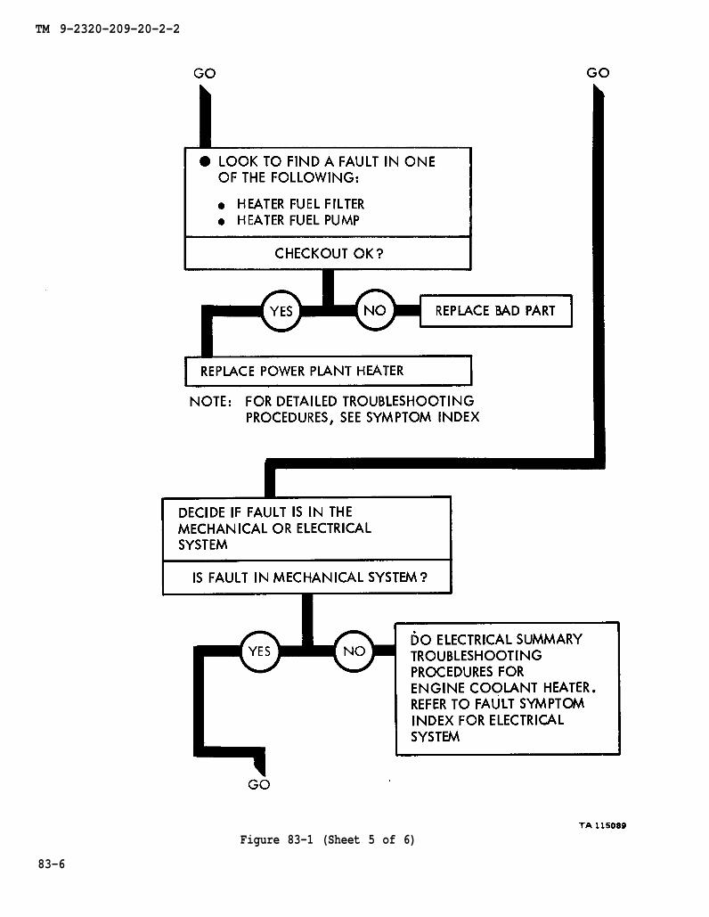
TM 9-2320-209-20-2-2
Figure 83-1 (Sheet 5 of 6)
83-6
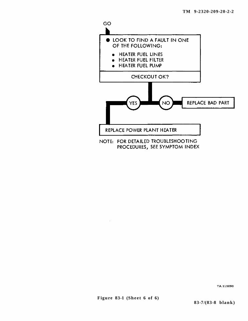
TM 9-2320-209-20-2-2
Figure 83-1 (Sheet 6 of 6)83-7/(83-8 blank)

TM 9-2320-209-20-2-2
CHAPTER 84
ENGINE COOLANT HEATER SUPPORT DIAGRAMS
84-1. GENERAL. This chapter gives the diaqrams you need when doing trouble-shooting procedures in chapterdiagrams used in this manual.
82. Table 3-1 is a complete listing of all support
84-1

TM 9-2320-209-20-2-2
Figure 84-1. Engine Coolant Heater Support Diagram
84-2

TM 9-2320-209-20-2-2
CHAPTER 85
ENGINE COLANT HEATER TEST PROCEDURES
85-1. GENERAL. This chapter gives test procedures for the tests given in chapter82, for the engine coolant heater.
85-2. TEST SET-UP. Instructions for setup of test equipment and parts to betested are given before the test procedures. Illustrations are used, when needed, toshow you how to hook up the test equipment to the part to be tested.
85-3. TEST PROCEDURE. Detailed step-by-step instructions, in flow chart form,are given for each test. The procedure calls out the type of test and the conditionof the truck system for each part of testing. The step-by-step test will lead you tothe bad component or to a fault symptom within a related system. Reference is madeto the fault symptom index, chapter 6, if the test shows a fault in another system.
85-1
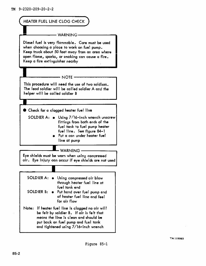
figure 84-1
TM 9-2320-209-20-2-2
Figure 85-1
85-2
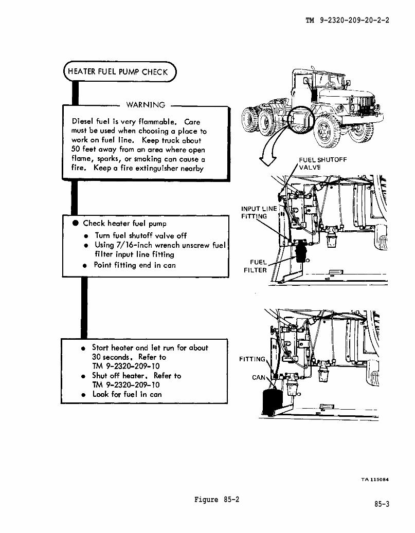
TM 9-2320-209-10
TM 9-2320-209-10
TM 9-2320-209-20-2-2
Figure 85-2 85-3


TM 9-2320-209-20-2-2
CHAPTER 86
ENGINE COOLANT HEATER CHECKOUT PROCEDURES
86-1. GENERAL. This chapter gives procedures for checking out the system aftertroubleshooting and repair have been done. Procedures are set up in flow chart formshowing the checkout steps in order and referring to the fault symptom index whenthe system does not checkout.
86-1
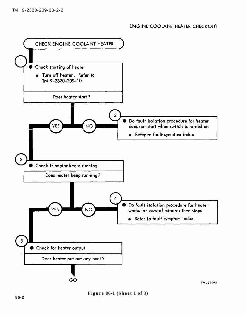
TM 9-2320-209-10
TM 9-2320-209-20-2-2
86-2Figure 86-1 (Sheet 1 of 3)
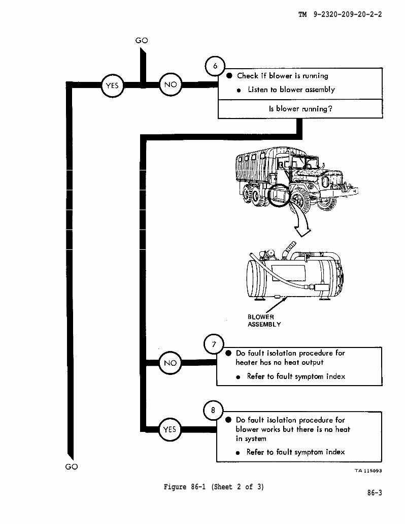
TM 9-2320-209-20-2-2
Figure 86-1 (Sheet 2 of 3)86-3

TM 9-2320-209-10
TM 9-2320-209-10
TM 9-2320-209-20-2-2
Figure 86-1 (Sheet 3 of 3)
86-4

TM 9-2320-209-20-2-2
CHAPTER 87
FUEL BURNING PERSONNEL HEATER TROUBLESHOOTING
87-1. EQUIPMENT ITEMS COVERED. This chapter gives equipment troubleshootingprocedures for the fuel burning personnel heater, for which there are authorizedcorrective maintenance tasks at the organizational maintenance level.
87-2. EQUIPMENT ITEMS NOT COVERED. All equipment items for which correctivemaintenance is authorized at the organizational maintenance level are covered in thischapter.
87-1
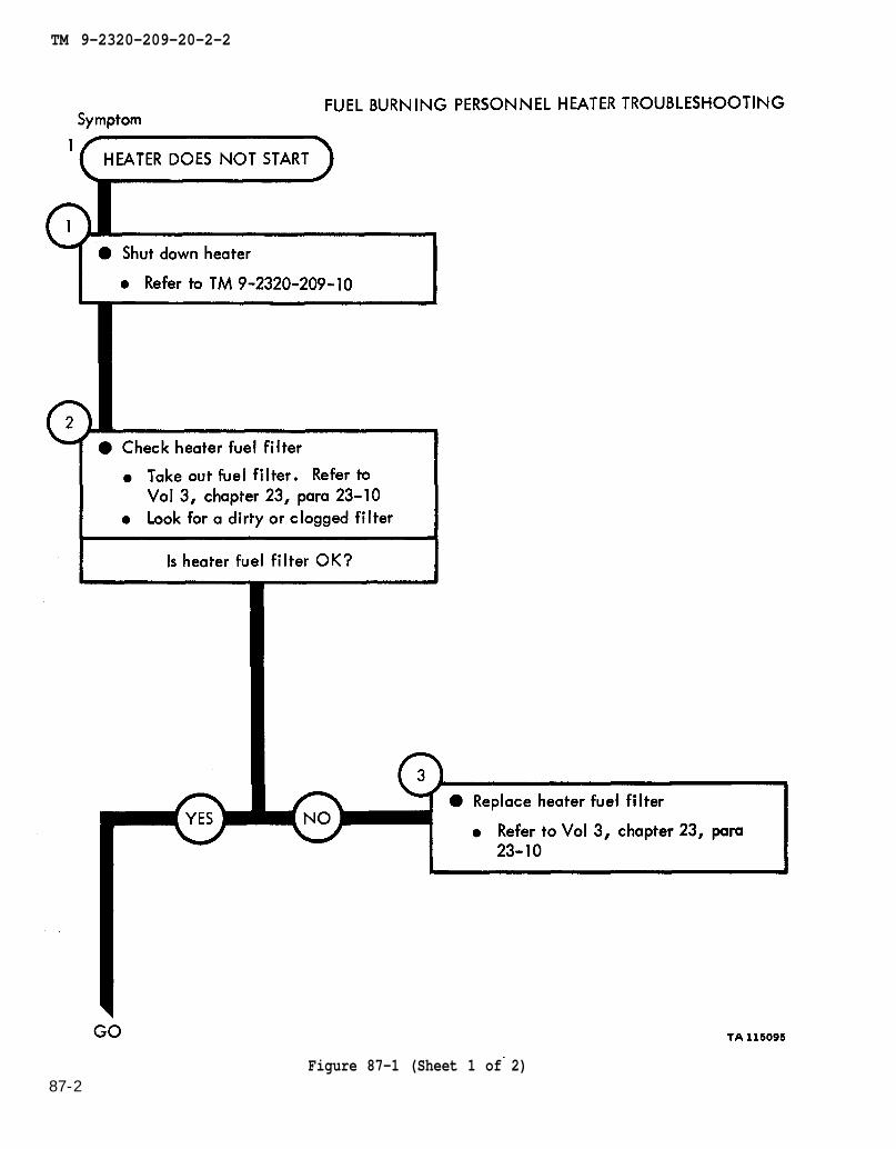
chapter 23
TM 9-2320-209-10
para 23-10
chapter 23 para 23-10
chapter 23
TM 9-2320-209-20-2-2
Figure 87-1 (Sheet 1 of 2)87-2

chapter 23 para 23-10
TM 9-2320-209-20-2-2
87-3Figure 87-1 (Sheet 2 of 2)

TM 9-2320-209-10
figure 89-1
figure 89-1
figure 89-1
TM 9-2320-209-20-2-2
Figure 87-2 (Sheet 1 of 3)
87-4
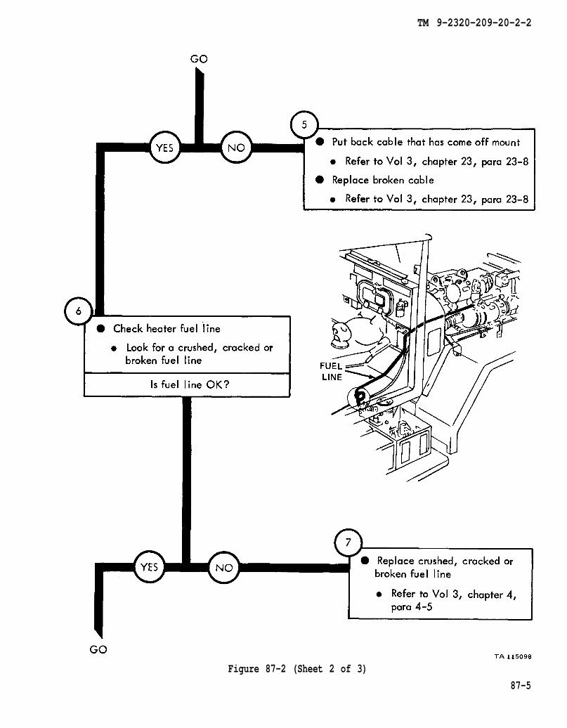
chapter 23
chapter 23
para 23-8
para 23-8
chapter 4
para 4-5
TM 9-2320-209-20-2-2
Figure 87-2 (Sheet 2 of 3)
87-5
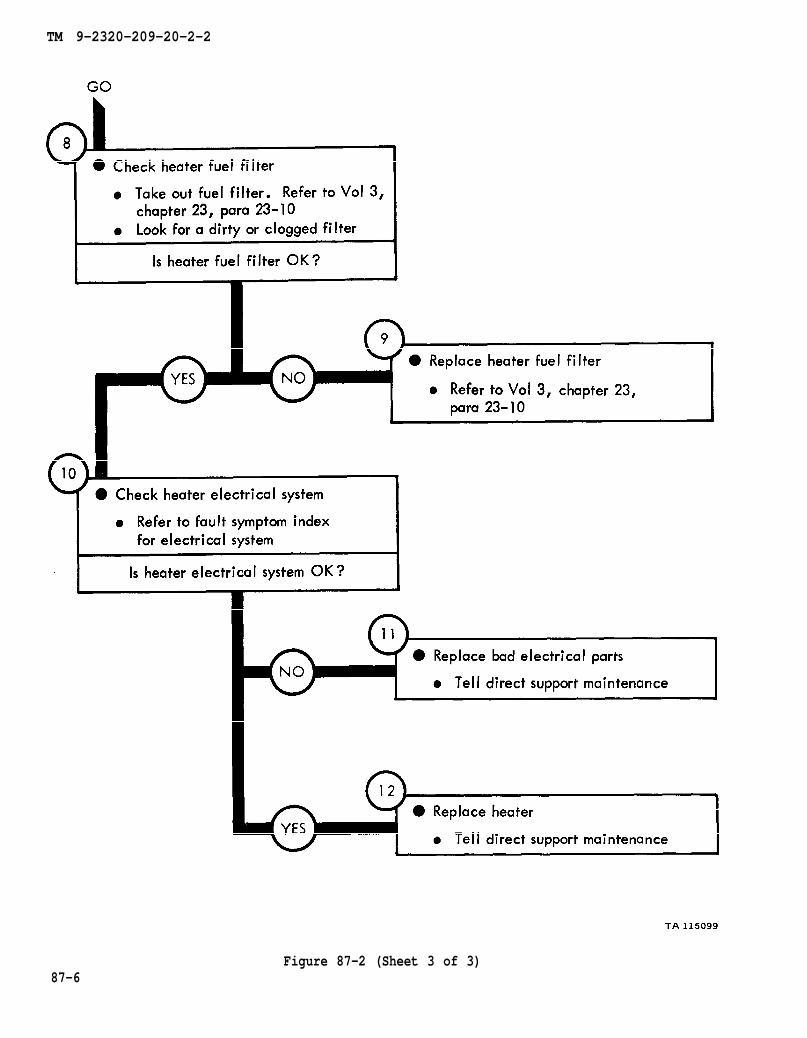
chapter 23 para 23-10
chapter 23
para 23-10
TM 9-2320-209-20-2-2
87-6Figure 87-2 (Sheet 3 of 3)
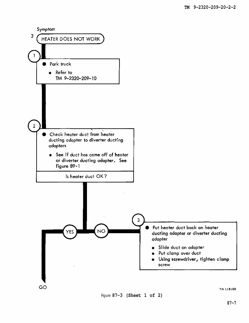
TM 9-2320-209-10
figure 89-1
TM 9-2320-209-20-2-2
Figure 87-3 (Sheet 1 of 2)
87-7
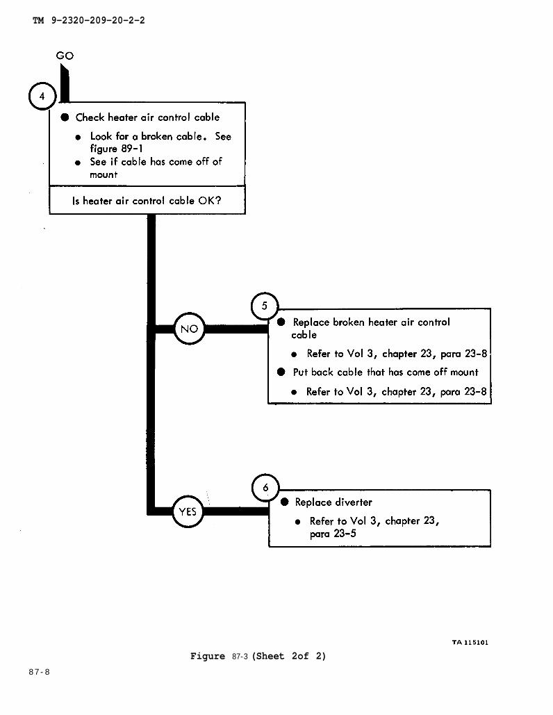
figure 89-1
chapter 23 para 23-8
chapter 23 para 23-8
chapter 23
para 23-5
TM 9-2320-209-20-2-2
Figure 87-3 (Sheet 2of 2)
8 7 - 8

TM 9-2320-209-10
figure 89-1
chapter 23 para 23-8
chapter 23 para 23-8
TM 9-2320-209-20-2-2
Figure 87-4 (Sheet 1 of 2)
87-9
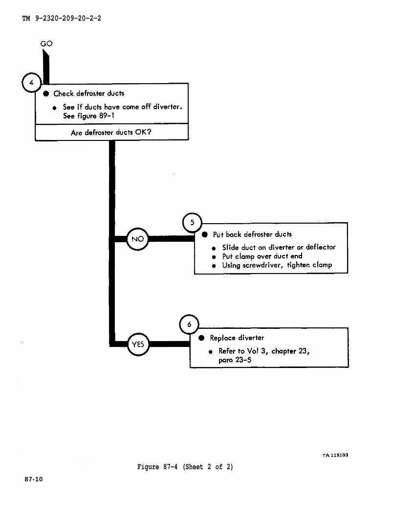
figure 89-1
chapter 23
para 23-5
TM 9-2320-209-20-2-2
Figure 87-4 (Sheet 2 of 2)
87-10
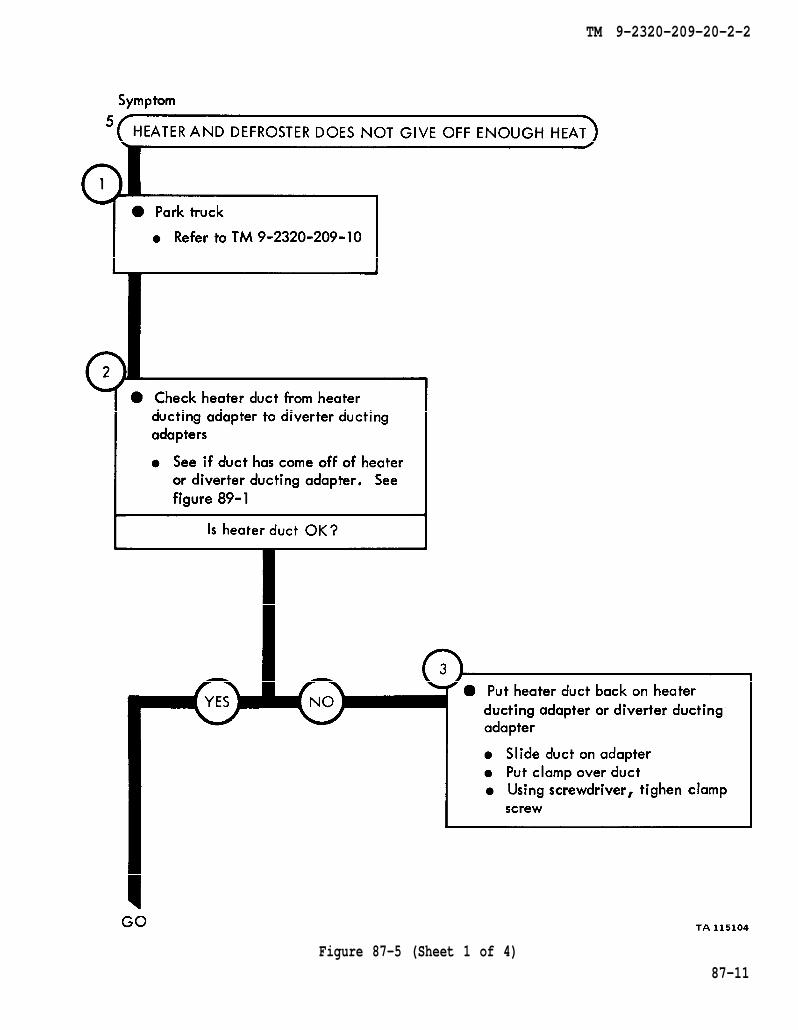
TM 9-2320-209-10
figure 89-1
TM 9-2320-209-20-2-2
Figure 87-5 (Sheet 1 of 4)87-11
figure 89-1
figure 89-1
chapter 23
chapter 23
para 23-8
para 23-8
figure 89-1
TM 9-2320-209-20-2-2
Figure 87-5 (Sheet 2 of 4)87-12

fig. 89-1
chapter 23
chapter 23
para 23-8
para 23-8
TM 9-2320-209-20-2-2
Figure 87-5 (Sheet 3 of 4)
87-13

chapter 4
chapter 23
para 23-10
para 4-5
para 23-10 chapter 23
TM 9-2320-209-20-2
87-14
Figure 87-5 (Sheet 4 of 4)
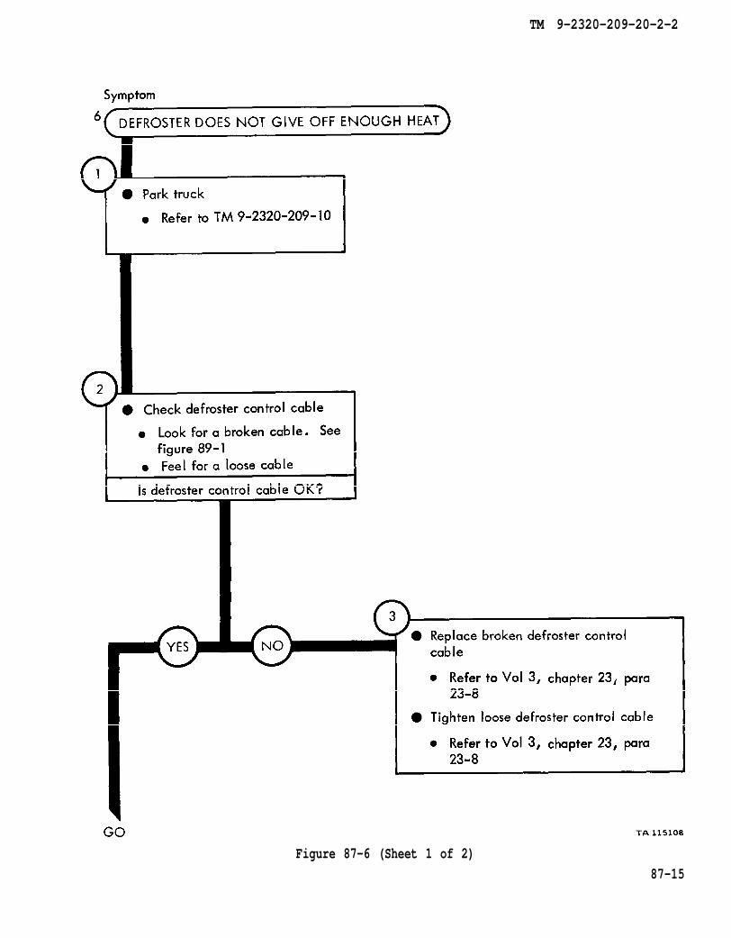
TM 9-2320-209-10
figure 89-1
chapter 23
chapter 23
para 23-8
para 23-8
TM 9-2320-209-20-2-2
Figure 87-6 (Sheet 1 of 2)
87-15

figure 89-1
chapter 23 para 23-5
TM 9-2320-209-20-2-2
87-16
Figure 87-6 (Sheet 2 of 2)
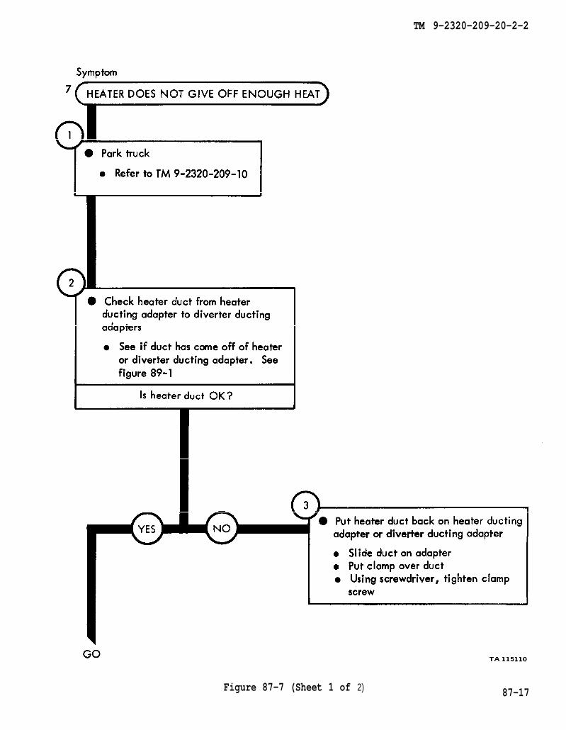
TM 9-2320-209-10
figure 89-1
TM 9-2320-209-20-2-2
Figure 87-7 (Sheet 1 of 2) 87-17

figure 89-1
chapter 23
chapter 23
para 23-8
para 23-8
chapter 23
para 23-5
TM 9-2320-208-20-2-2
Figure 87-7 (Sheet 2 of 2)
87-18
TM 9-2320-209-20-2-2
CHAPTER 88FUEL BURNING PERSONNEL HEATERTROUBLESHOOTING SUMMARY
88-1. GENERAL. This chapter gives a summary of troubleshooting procedures givenin chapter 87 for the fuel burning personnel heater.
88-2. PROCEDURES. The summary in this chapter covers all fault symptoms foundin the detailed troubleshooting procedures. Chapter 7 outlines a sample troubleshoot-ing procedure. The summary procedures are based on the “what-to-do” portions ofthe detailed procedures and do not include the “how-to-do-it” instructions. Warn-inzs, cautions, and notes are tiven where needed.
88-1
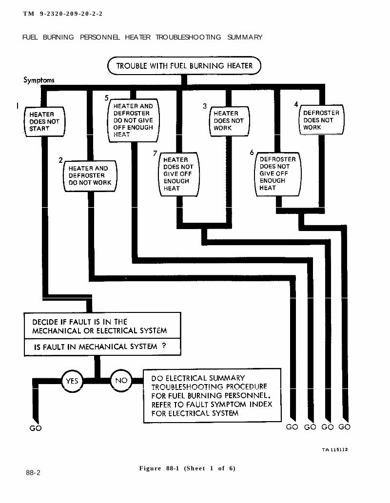
TM 9-2320-209-20-2-2
FUEL BURNING PERSONNEL HEATER TROUBLESHOOTING SUMMARY
88-2Figure 88-1 (Sheet 1 of 6)
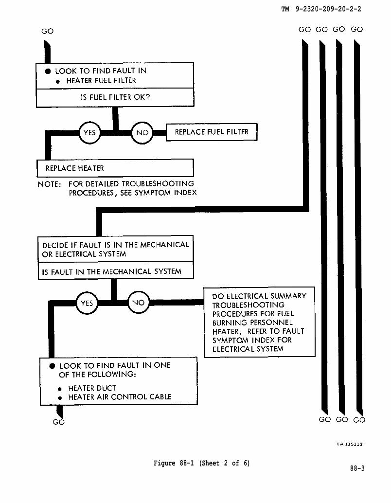
TM 9-2320-209-20-2-2
Figure 88-1 (Sheet 2 of 6)88-3
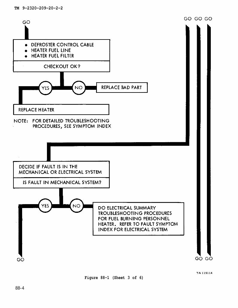
TM 9-2320-209-20-2-2
Figure 88-1 (Sheet 3 of 6)
88-4
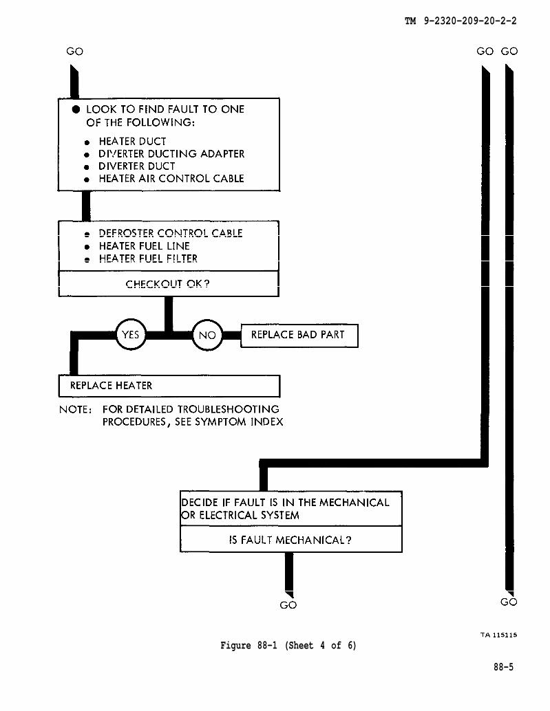
TM 9-2320-209-20-2-2
Figure 88-1 (Sheet 4 of 6)
88-5
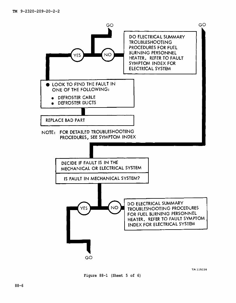
TM 9-2320-209-20-2-2
Figure 88-1 (Sheet 5 of 6)
88-6
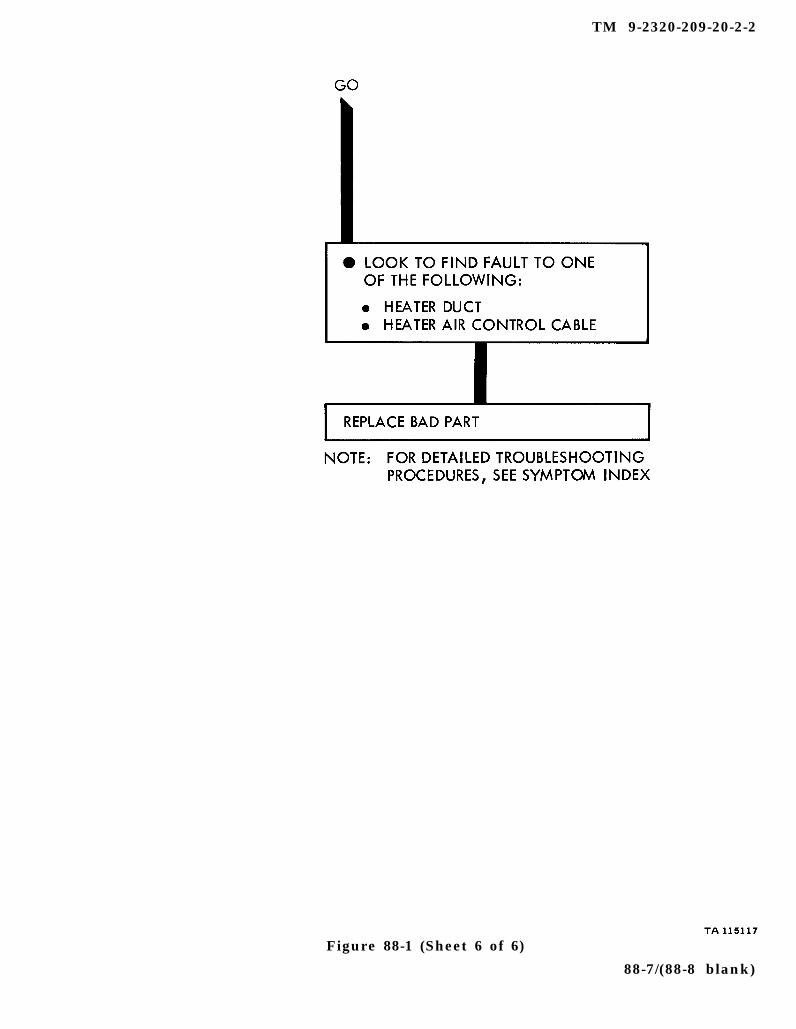
TM 9-2320-209-20-2-2
Figure 88-1 (Sheet 6 of 6)
88-7/(88-8 blank)

TM 9-2320-209-20-2-2
CHAPTER 89
FUEL BURNING PERSONNEL HEATER SUPPORT DIAGRAMS
89-1. GENERAL. This chapter gives the diagrams you need when doing trouble-shooting procedures in chapter 87. Table 3-1 is a complete listing of all supportdiagrams used in this manual.
89-1
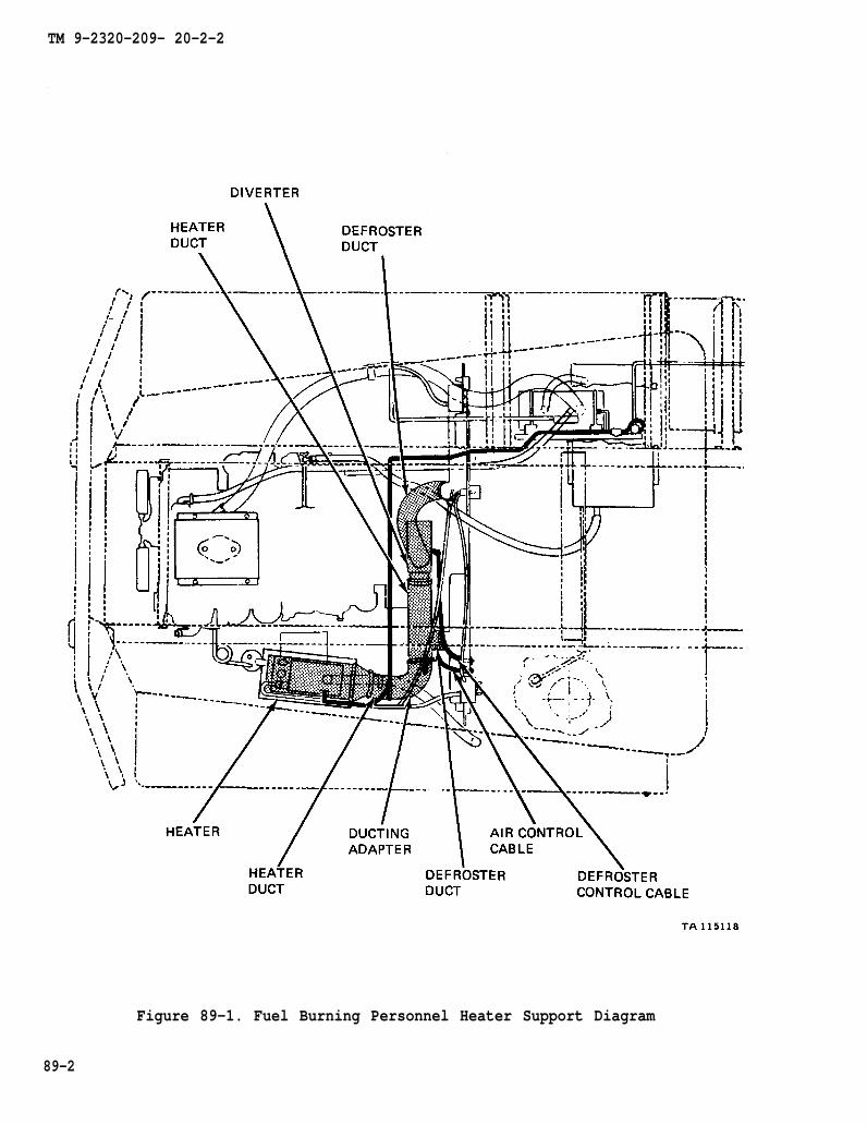
TM 9-2320-209- 20-2-2
Figure 89-1. Fuel Burning Personnel Heater Support Diagram
89-2

TM 9-2320-209-20-2-2
CHAPTER 90
FUEL BURNING PERSONNEL HEATER CHECKOUT PROCEDURES
90-1. GENERAL. This chapter gives procedures for checking out the system aftertroubleshooting and repair have been done. Procedures are set up in flow chart formshowing the checkout steps in order and referring to the fault symptom index whenthe system does not check out.
90-1
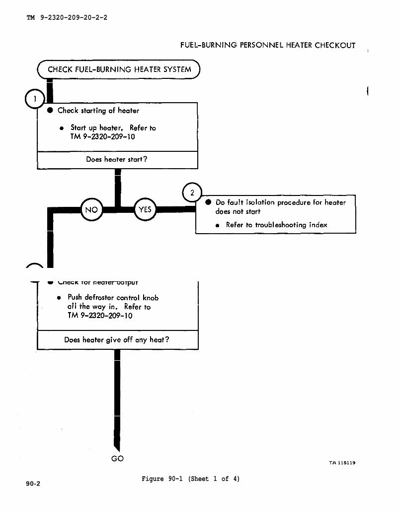
TM 9-2320-209-10
TM 9-2320-209-10
TM 9-2320-209-20-2-2
90-2Figure 90-1 (Sheet 1 of 4)
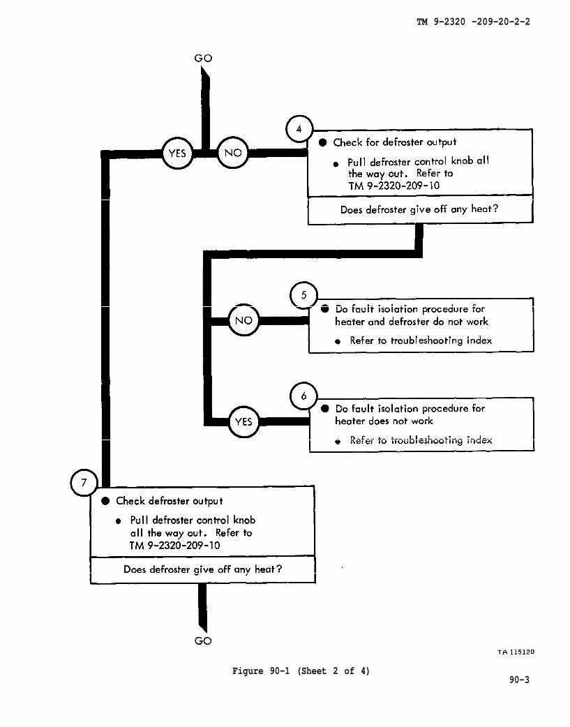
TM 9-2320-209-10
TM 9-2320-209-10
TM 9-2320 -209-20-2-2
Figure 90-1 (Sheet 2 of 4)90-3
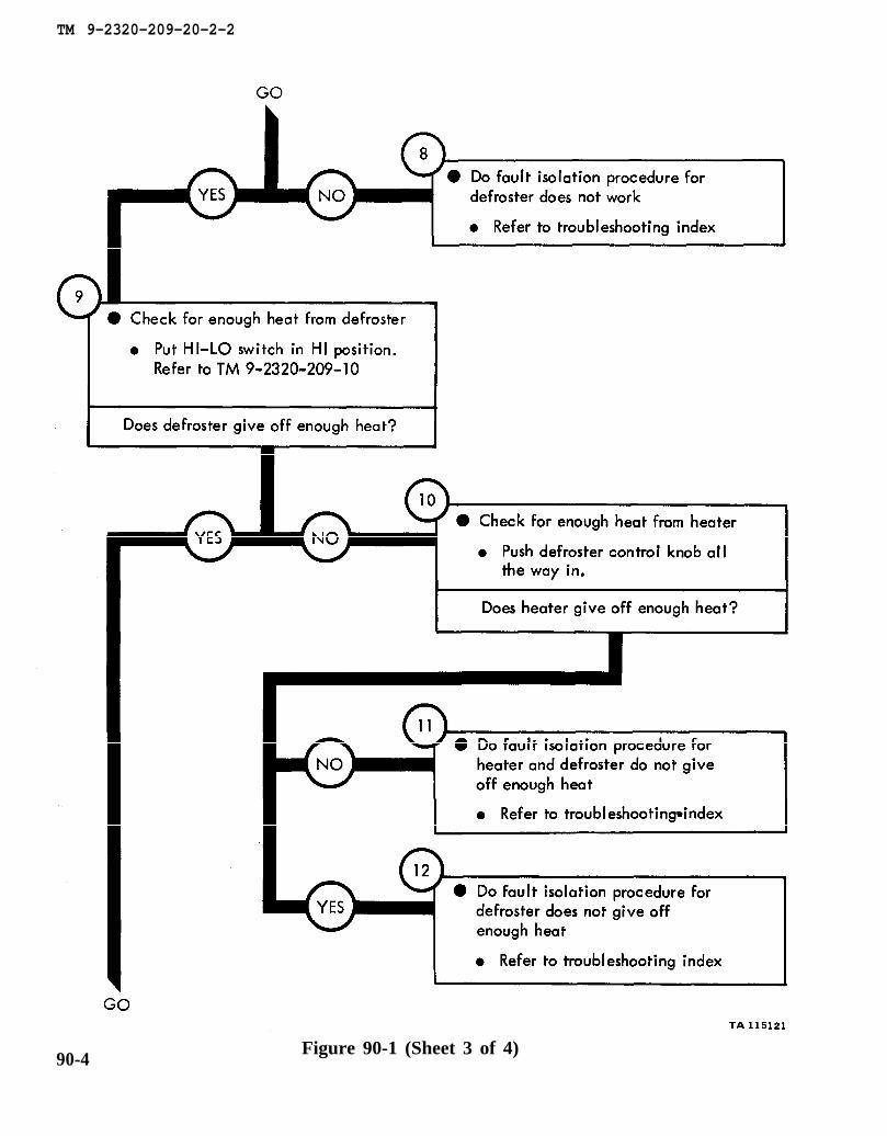
TM 9-2320-209-10
TM 9-2320-209-20-2-2
Figure 90-1 (Sheet 3 of 4)90-4
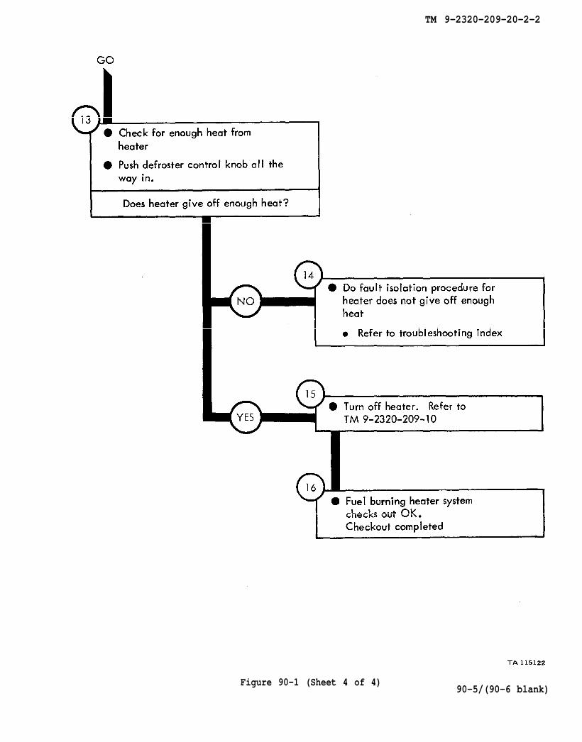
TM 9-2320-209-10
TM 9-2320-209-20-2-2
Figure 90-1 (Sheet 4 of 4)90-5/(90-6 blank)

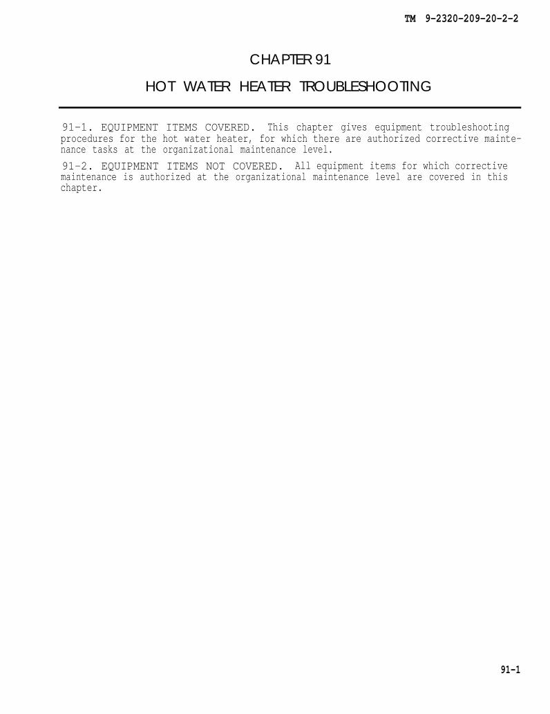
TM 9-2320-209-20-2-2
CHAPTER 91
HOT WATER HEATER TROUBLESHOOTING
91-1. EQUIPMENT ITEMS COVERED. This chapter gives equipment troubleshootingprocedures for the hot water heater, for which there are authorized corrective mainte-nance tasks at the organizational maintenance level.
91-2. EQUIPMENT ITEMS NOT COVERED. All equipment items for which correctivemaintenance is authorized at the organizational maintenance level are covered in thischapter.
91-1
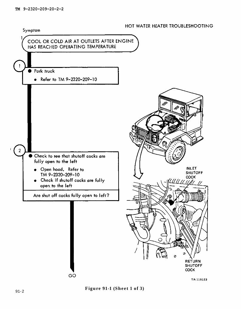
TM 9-2320-209-10
TM 9-2320-209-10
TM 9-2320-209-20-2-2
91-2Figure 91-1 (Sheet 1 of 3)
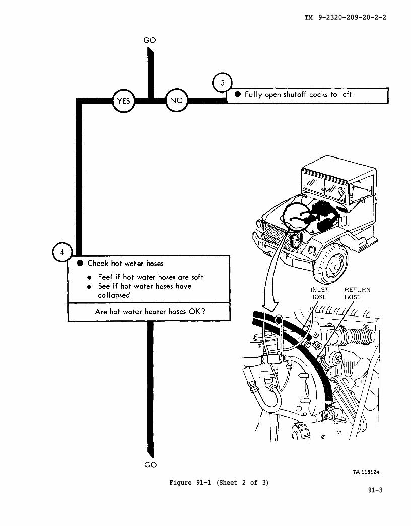
TM 9-2320-209-20-2-2
Figure 91-1 (Sheet 2 of 3)91-3

chapter 23
para 23-18
TM 9-2320-209-20-2-2
91-4Figure 91-1 (Sheet 3 of 3)
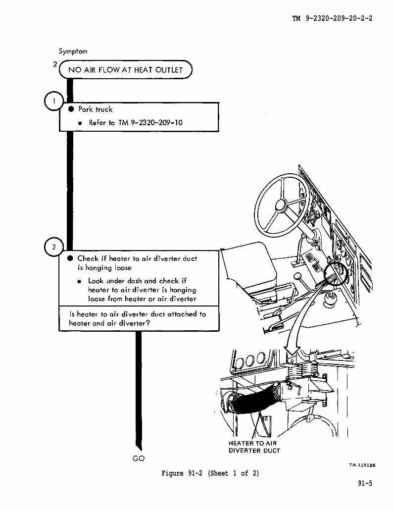
TM 9-2320-209-10
TM 9-2320-209-20-2-2
Figure 91-2 (Sheet 1 of 2)91-5
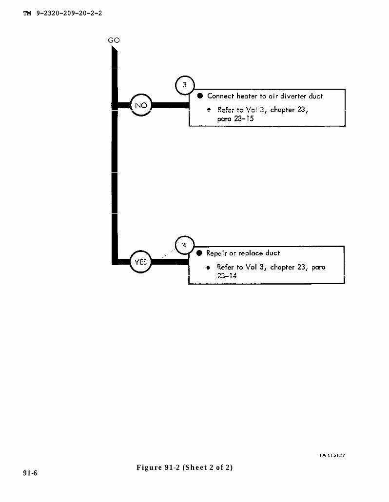
chapter 23
chapter 23 para 23-14
para 23-15
TM 9-2320-209-20-2-2
91-6Figure 91-2 (Sheet 2 of 2)
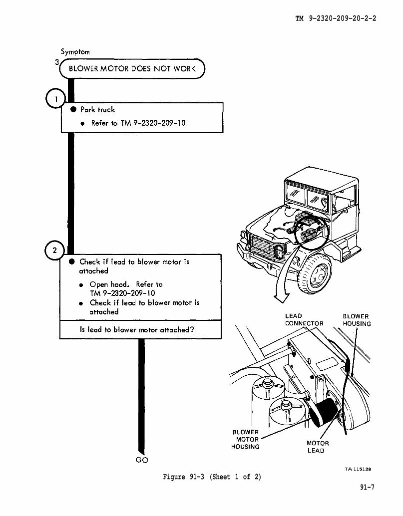
TM 9-2320-209-10
TM 9-2320-209-10
TM 9-2320-209-20-2-2
Figure 91-3 (Sheet 1 of 2)91-7
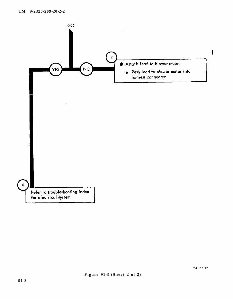
TM 9-2320-209-20-2-2
Figure 91-3 (Sheet 2 of 2)91-8
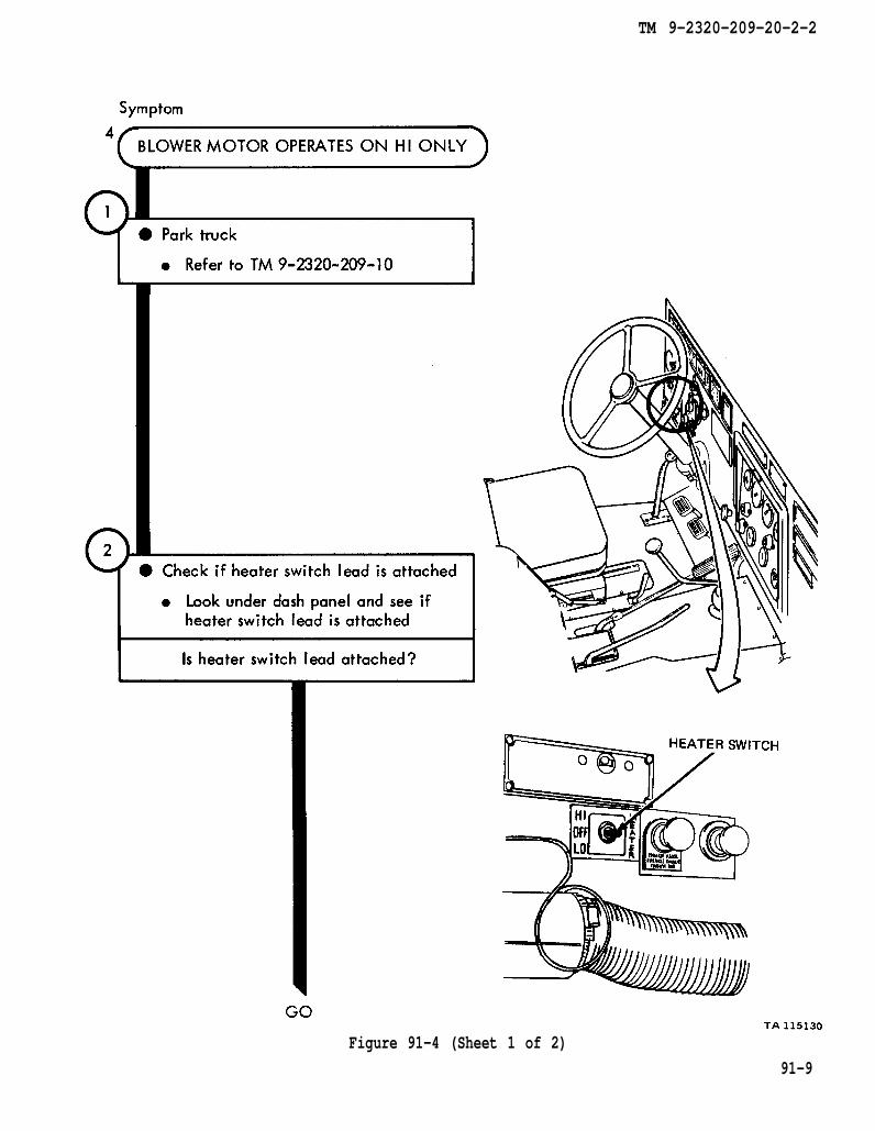
TM 9-2320-209-10
TM 9-2320-209-20-2-2
Figure 91-4 (Sheet 1 of 2)
91-9
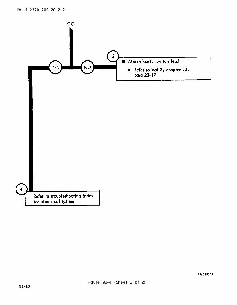
chapter 23
para 23-17
TM 9-2320-209-20-2-2
91-10Figure 91-4 (Sheet 2 of 2)
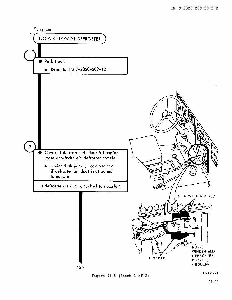
TM 9-2320-209-10
TM 9-2320-209-20-2-2
Figure 91-5 (Sheet 1 of 2)
91-11

chapter 23
para 23-14
chapter 23
para 23-14
chapter 23
para 23-14
TM 9-2320-209-20-2-2
Figure 91-5 (Sheet 2 of 2)91-12
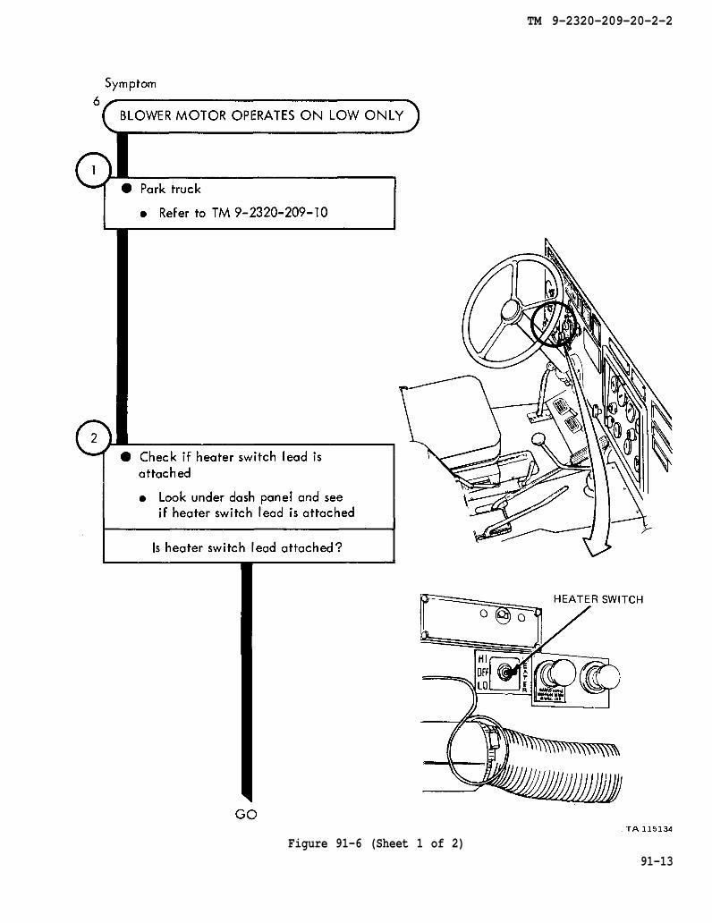
TM 9-2320-209-10
TM 9-2320-209-20-2-2
Figure 91-6 (Sheet 1 of 2)91-13

chapter 23
para 23-17
TM 9-2320-209-20-2-2
91-14Figure 91-6 (Sheet 2 of 2)
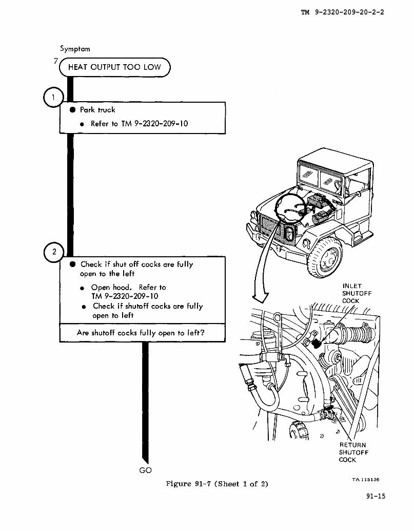
Figure 91-7
TM 9-2320-209-10
TM 9-2320-209-10
TM 9-2320-209-20-2-2
91-15

TM 9-2320-209-20-2-2
91-16Figure 91-7 (Sheet 2 of 2)

TM 9-2320-209-20-2-2
CHAPTER 92
HOT WATER HEATER TROUBLESHOOTING SUMMARY
92-1. GENERAL. This chapter gives a summary of troubleshooting procedures givenin chapter 91 for the hot water heater.
92-2. PROCEDURES. The summary in this chapter covers all fault symptoms foundin the detailed troubleshooting procedures. Chapter 7 outlines a sample troubleshoot-ing procedure. The summary procedures are based on the “what-to-do” portions ofthe detailed procedures and do not include the “how -to-do-it” instructions. Warn-ings, cautions, and notes are given where needed.
92-1
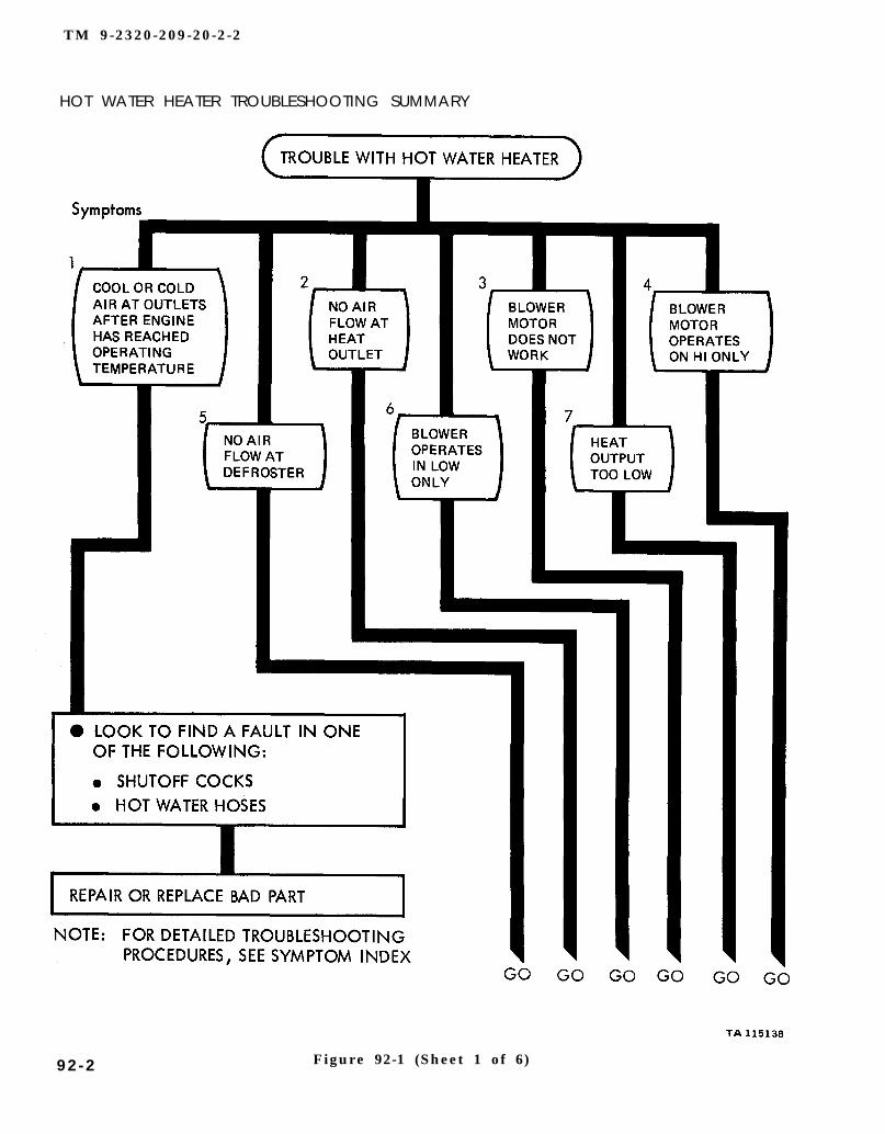
TM 9-2320-209-20-2-2
HOT WATER HEATER TROUBLESHOOTING SUMMARY
Figure 92-1 (Sheet 1 of 6)92-2
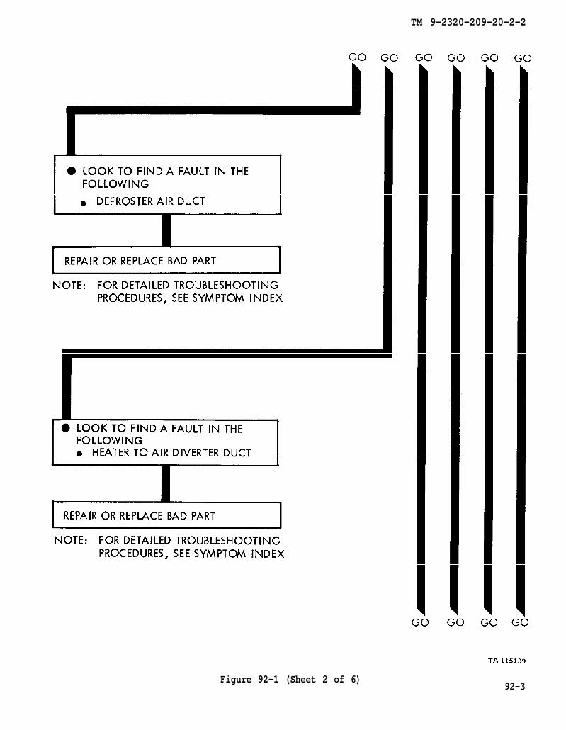
TM 9-2320-209-20-2-2
Figure 92-1 (Sheet 2 of 6)92-3
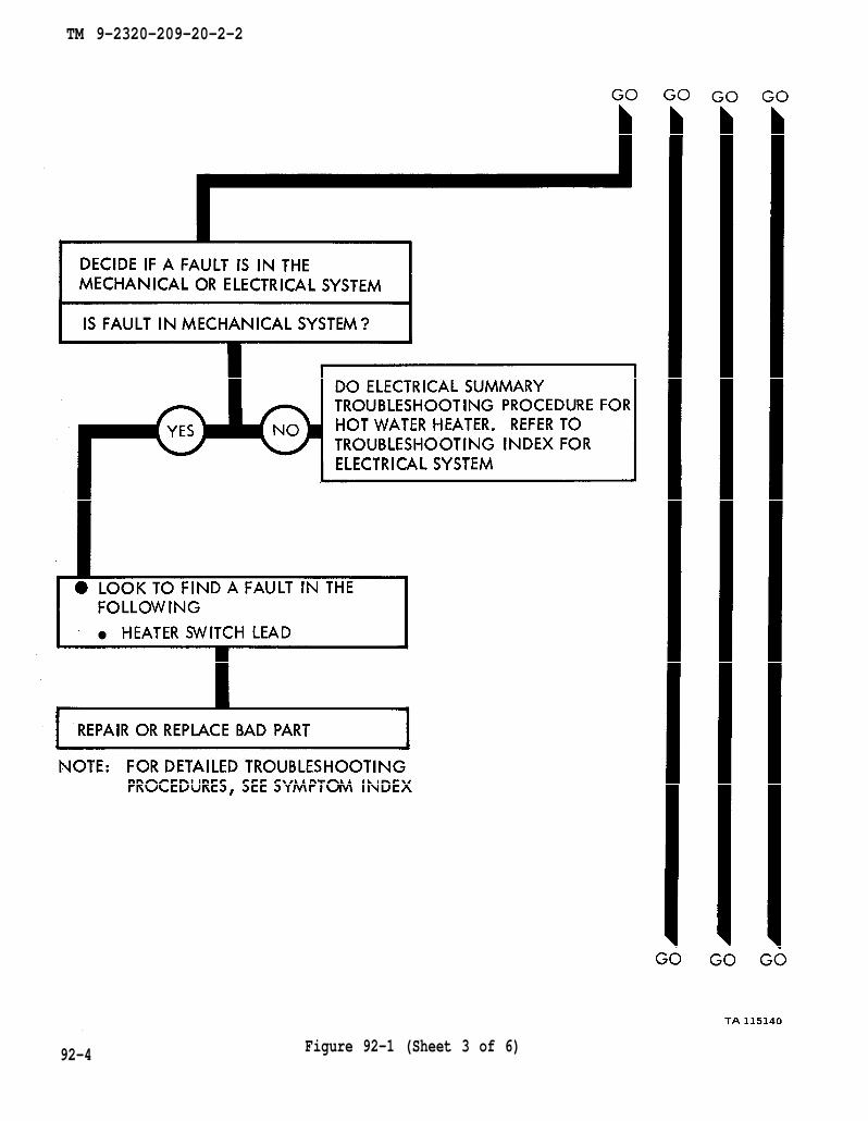
TM 9-2320-209-20-2-2
92-4 Figure 92-1 (Sheet 3 of 6)

TM 9-2320-209-20-2-2
Figure 92-1 (Sheet 4 of 6)92-5

TM 9-2320-209-20-2-2
92-6Figure 92-1 (Sheet 5 of 6)
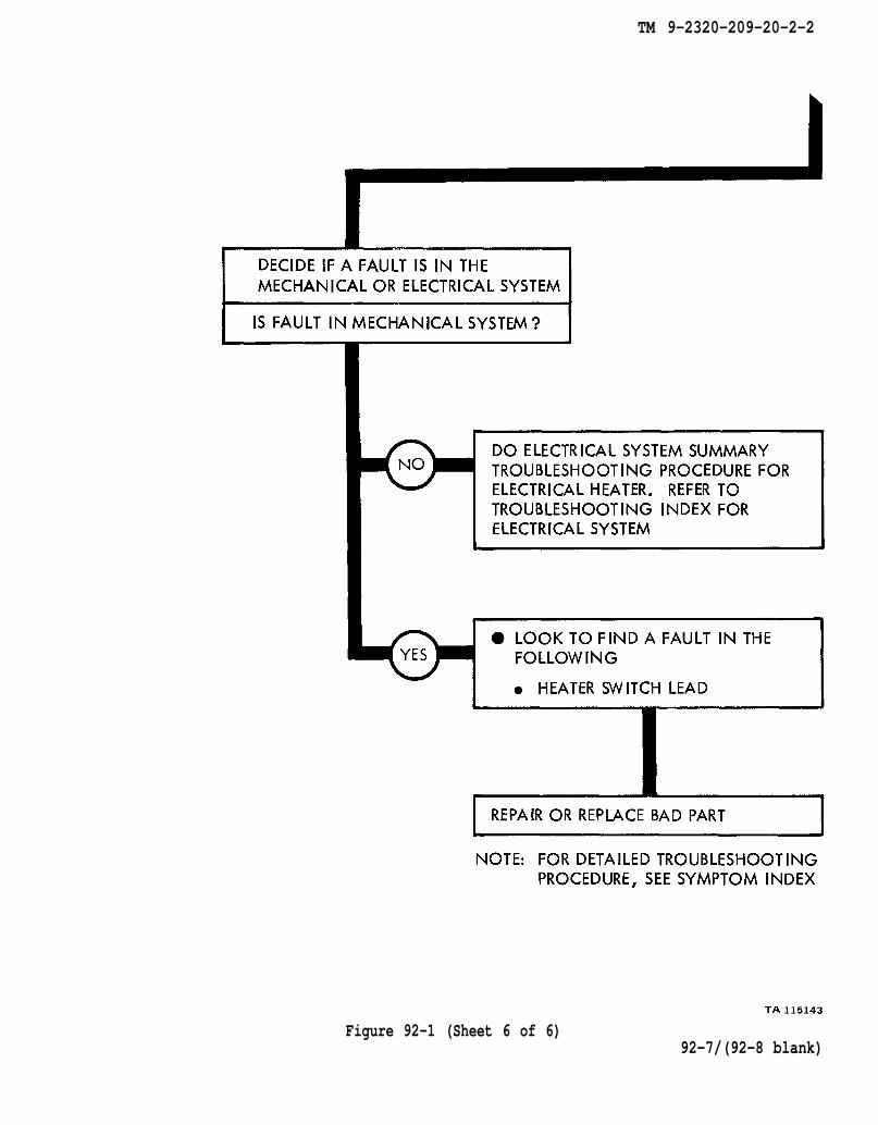
TM 9-2320-209-20-2-2
Figure 92-1 (Sheet 6 of 6)92-7/(92-8 blank)

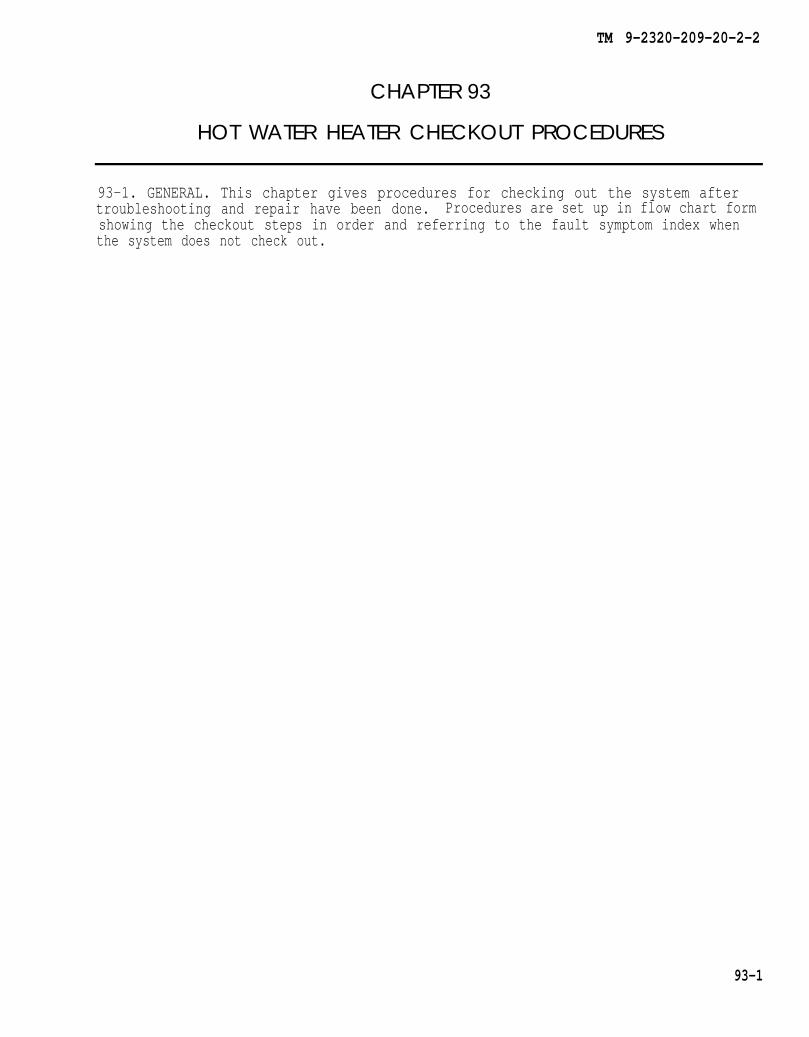
TM 9-2320-209-20-2-2
CHAPTER 93
HOT WATER HEATER CHECKOUT PROCEDURES
93-1. GENERAL. This chapter gives procedures for checking out the system aftertroubleshooting and repair have been done. Procedures are set up in flow chart formshowing the checkout steps in order and referring to the fault symptom index whenthe system does not check out.
93-1
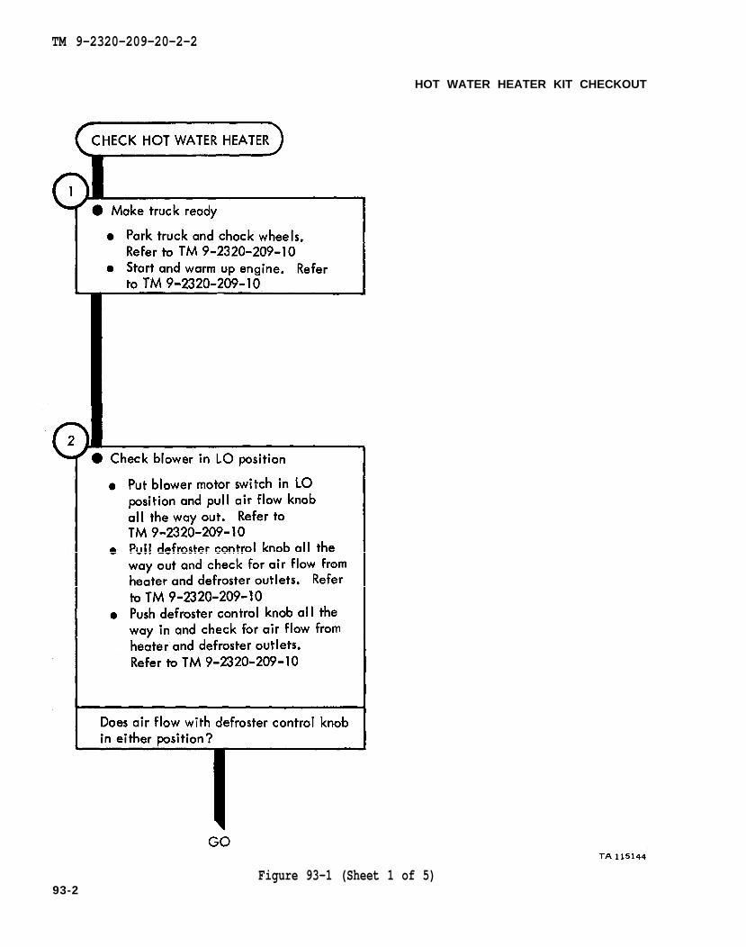
TM 9-2320-209-10
TM 9-2320-209-10
TM 9-2320-209-10
TM 9-2320-209-10
TM 9-2320-209-10
TM 9-2320-209-20-2-2
HOT WATER HEATER KIT CHECKOUT
Figure 93-1 (Sheet 1 of 5)93-2
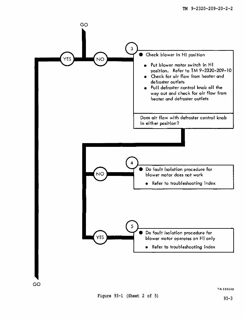
TM 9-2320-209-10
TM 9-2320-209-20-2-2
Figure 93-1 (Sheet 2 of 5) 93-3
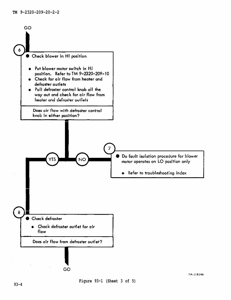
TM 9-2320-209-10
TM 9-2320-209-20-2-2
93-4Figure 93-1 (Sheet 3 of 5)

TM 9-2320-209-20-2-2
Figure 93-1 (Sheet 4 of 5) 93-5

TM 9-2320-209-10
TM 9-2320-209-10
TM 9-2320-209-20-2-2
93-6Figure 93-1 (Sheet 5 of 5)

TM 9-2320-209-20-2-2
CHAPTER 94
DEEP WATER FORDING KIT TROUBLESHOOTING
94-1. EQUIPMENT ITEMS COVERED. This chapter gives equipment troubleshootingprocedures for the deep water fording kit, for which there are authorized correctivemaintenance tasks at the organizational maintenance level.
94-2. EQUIPMENT ITEMS NOT COVERED. All equipment items for which correctivemaintenance is authorized at the organizational maintenance level are covered in thischapter.
94-1
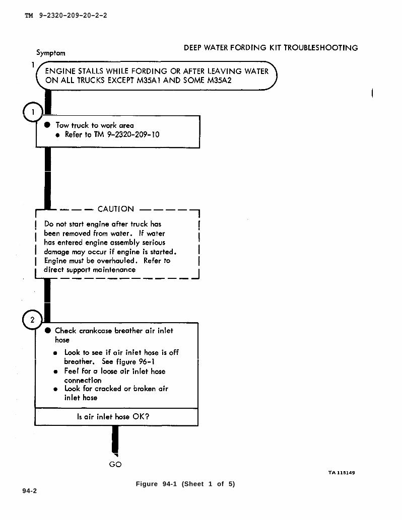
TM 9-2320-209-10
figure 96-1
TM 9-2320-209-20-2-2
94-2Figure 94-1 (Sheet 1 of 5)
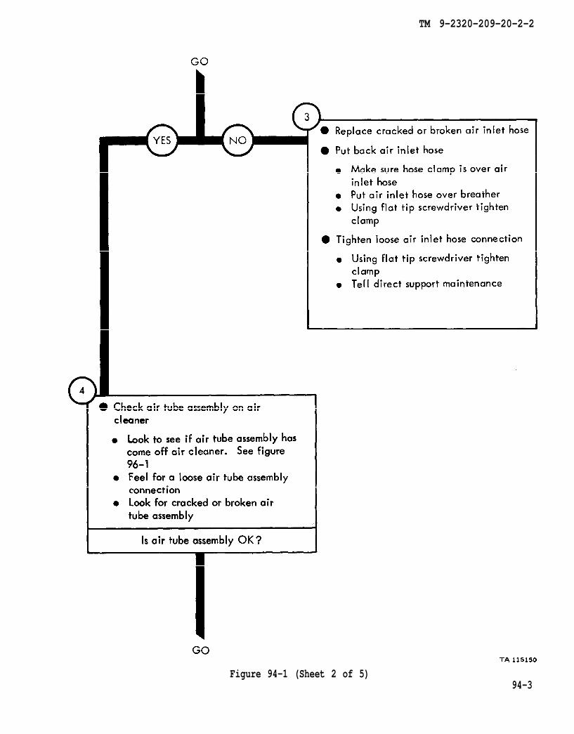
figure 96-1
TM 9-2320-209-20-2-2
Figure 94-1 (Sheet 2 of 5)94-3

TM 9-2320-209-10
TM 9-2320-209-20-2-2
Figure 94-1 (Sheet 3 of 5)94-4
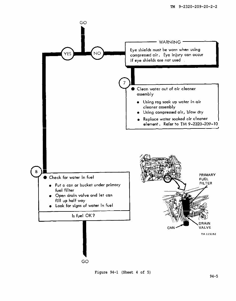
TM 9-2320-209-10
TM 9-2320-209-20-2-2
Figure 94-1 (Sheet 4 of 5)94-5
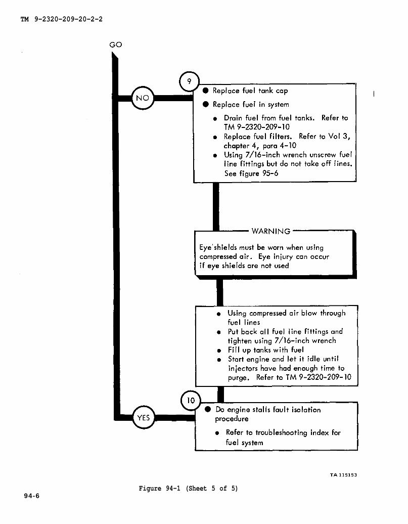
TM 9-2320-209-10
chapter 4 para 4-10
TM 9-2320-209-10
figure 95-6
TM 9-2320-209-20-2-2
94-6Figure 94-1 (Sheet 5 of 5)
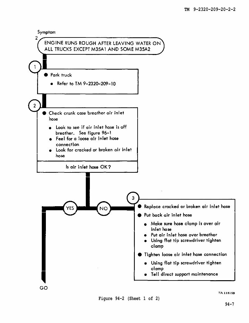
TM 9-2320-209-10
figure 96-1
TM 9-2320-209-20-2-2
Figure 94-2 (Sheet 1 of 2)94-7
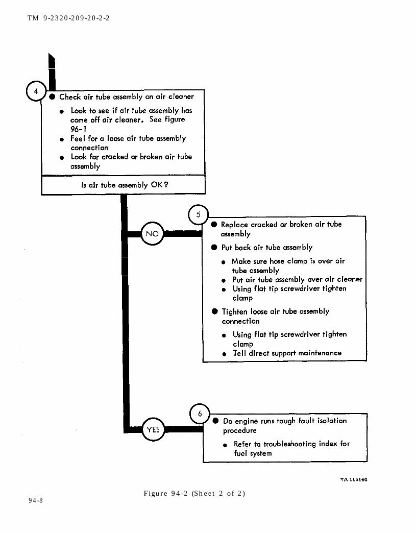
figure 96-1
TM 9-2320-209-20-2-2
94-8Figure 94-2 (Sheet 2 of 2)
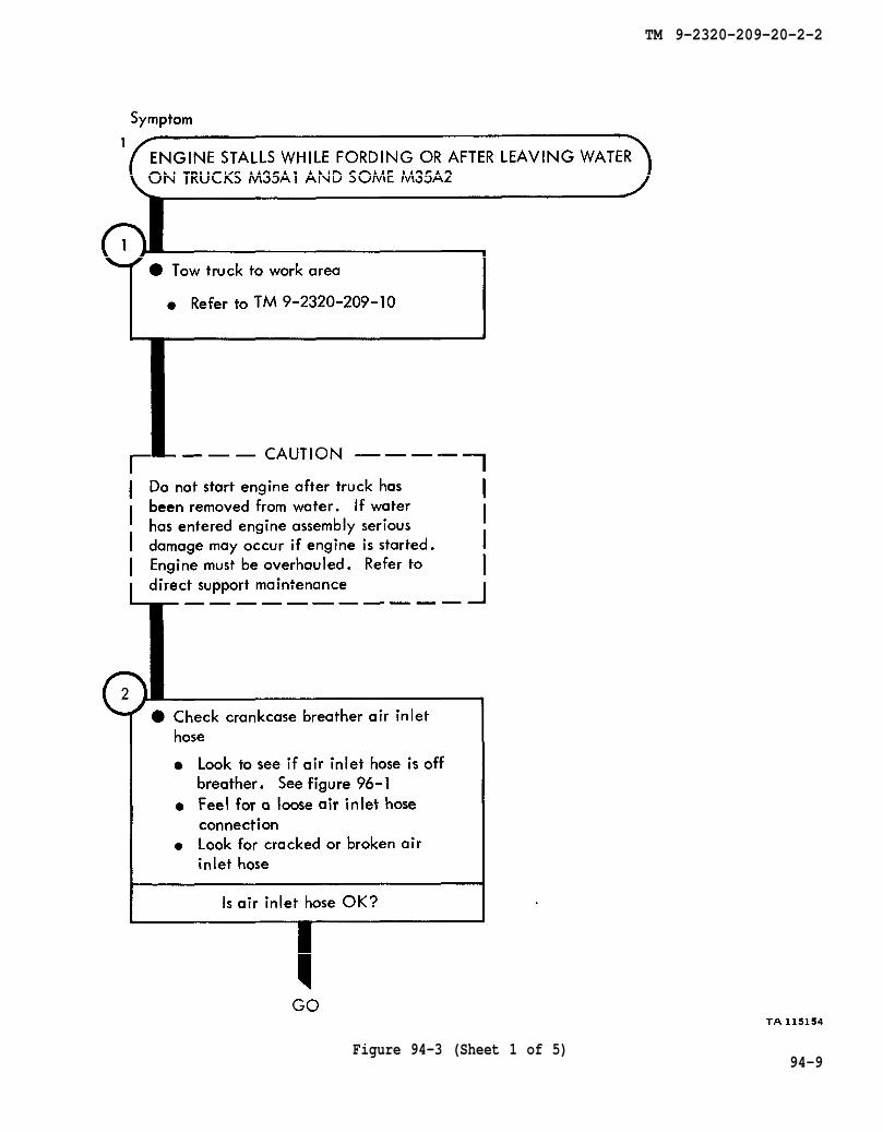
TM 9-2320-209-10
figure 96-1
TM 9-2320-209-20-2-2
Figure 94-3 (Sheet 1 of 5)94-9
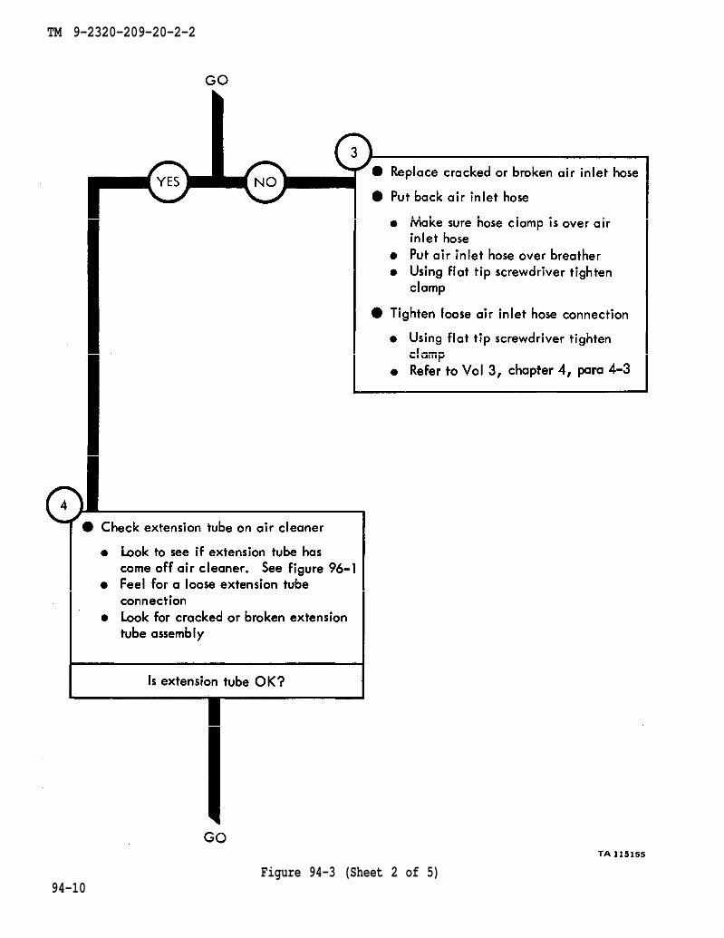
chapter 4 para 4-3
figure 96-1
TM 9-2320-209-20-2-2
94-10Figure 94-3 (Sheet 2 of 5)

chapter 4 para 4-3
TM 9-2320-209-10
TM 9-2320-209-20-2-2
Figure 94-3 (Sheet 3 of 5)94-11
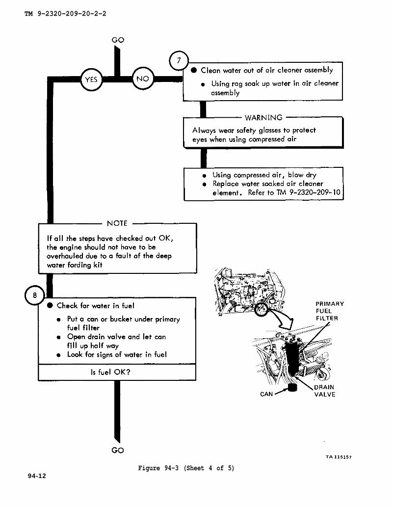
TM 9-2320-209-10
TM 9-2320-209-20-2-2
Figure 94-3 (Sheet 4 of 5)94-12
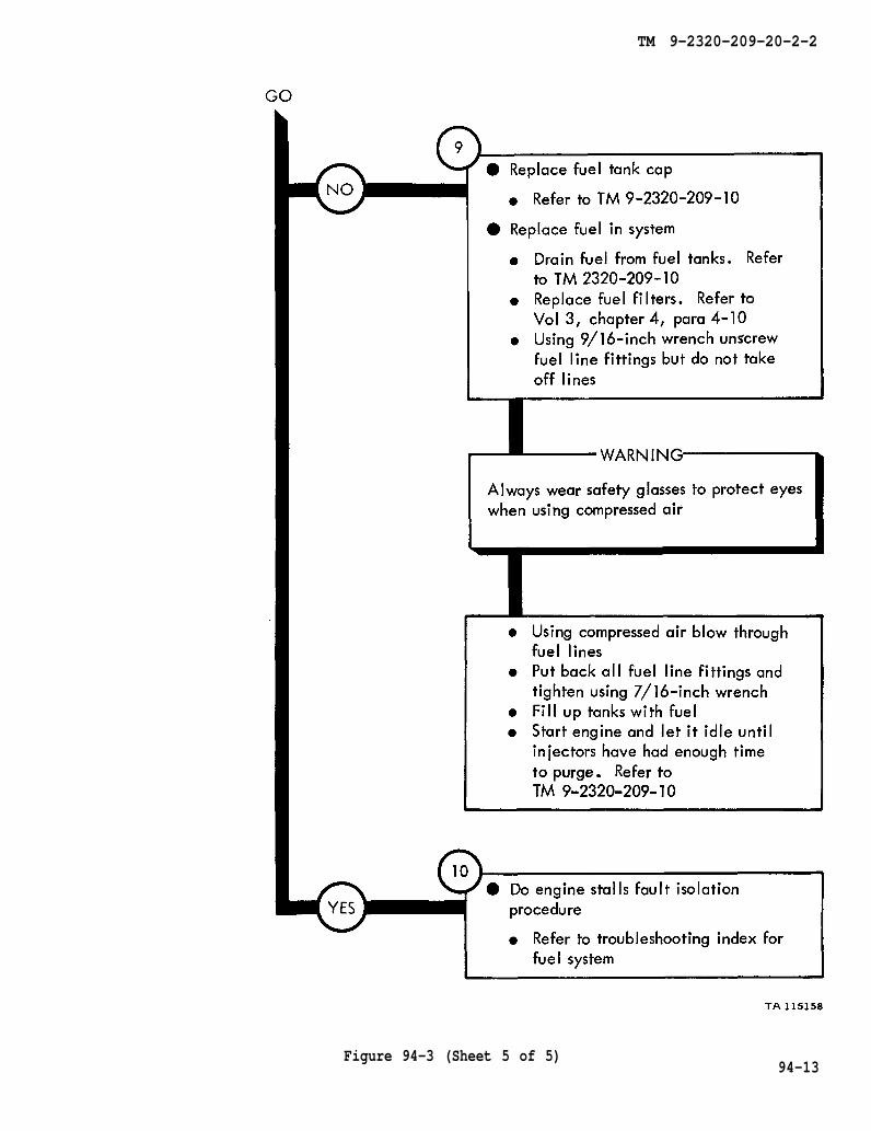
TM 9-2320-209-10
TM 2320-209-10
chapter 4 para 4-10
TM 9-2320-209-10
TM 9-2320-209-20-2-2
Figure 94-3 (Sheet 5 of 5)94-13
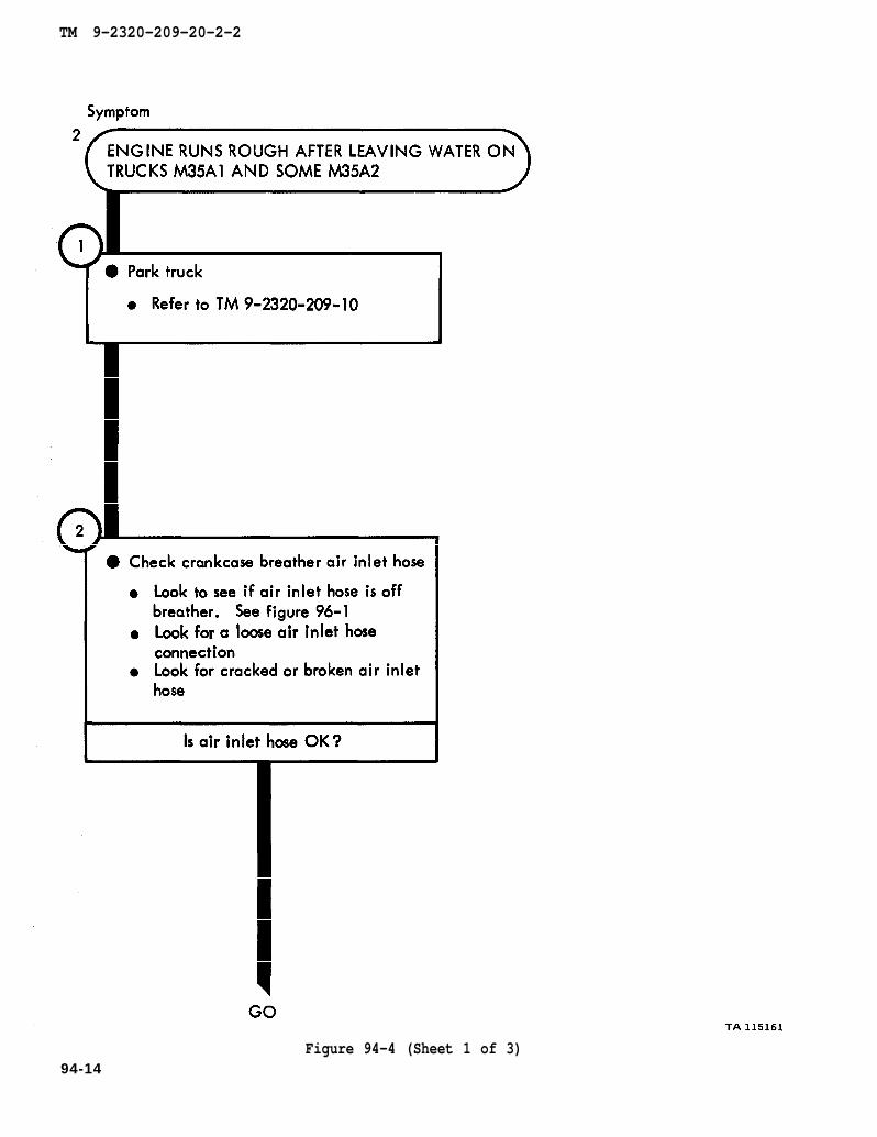
TM 9-2320-209-10
figure 96-1
TM 9-2320-209-20-2-2
Figure 94-4 (Sheet 1 of 3)94-14
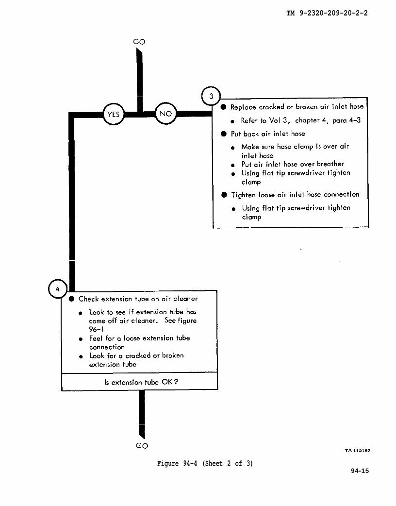
chapter 4 para 4-3
figure 96-1
TM 9-2320-209-20-2-2
Figure 94-4 (Sheet 2 of 3)94-15
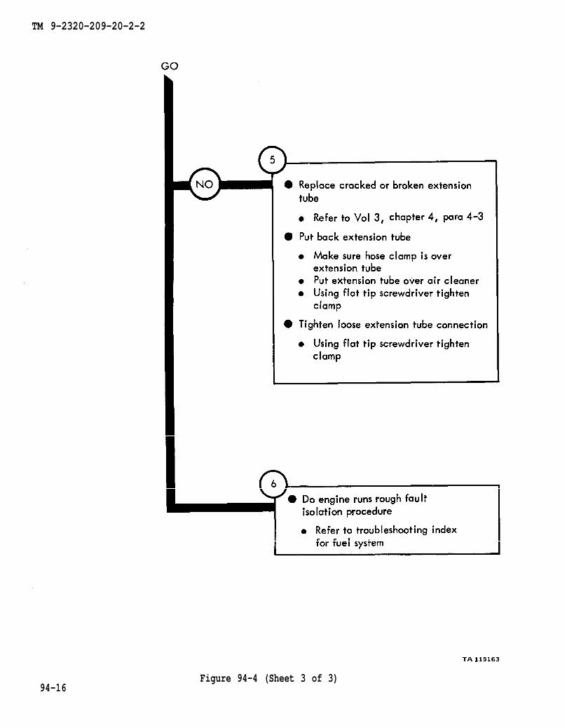
chapter 4 para 4-3
TM 9-2320-209-20-2-2
Figure 94-4 (Sheet 3 of 3)94-16

TM 9-2320-209-10
figure 96-3
chapter 23 para 23-31
TM 9-2320-209-20-2-2
Figure 94-594-17
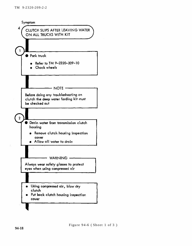
TM 9-2320-209-10
TM 9-2320-209-2-2
94-18Figure 94-6 ( Sheet 1 of 3 )

figure 96-2
TM 9-237
TM 9-2320-209-10
figure 96-3
TM 9-2320-209-10
TM 9-2320-209-20-2-2
Figure 94-5 ( Sheet 2 of 3 )94-19

chapter 13 para 13-21
TM 9-2320-209-20-2-2
94-20Figure 94-6 (Sheet 3 of 3)
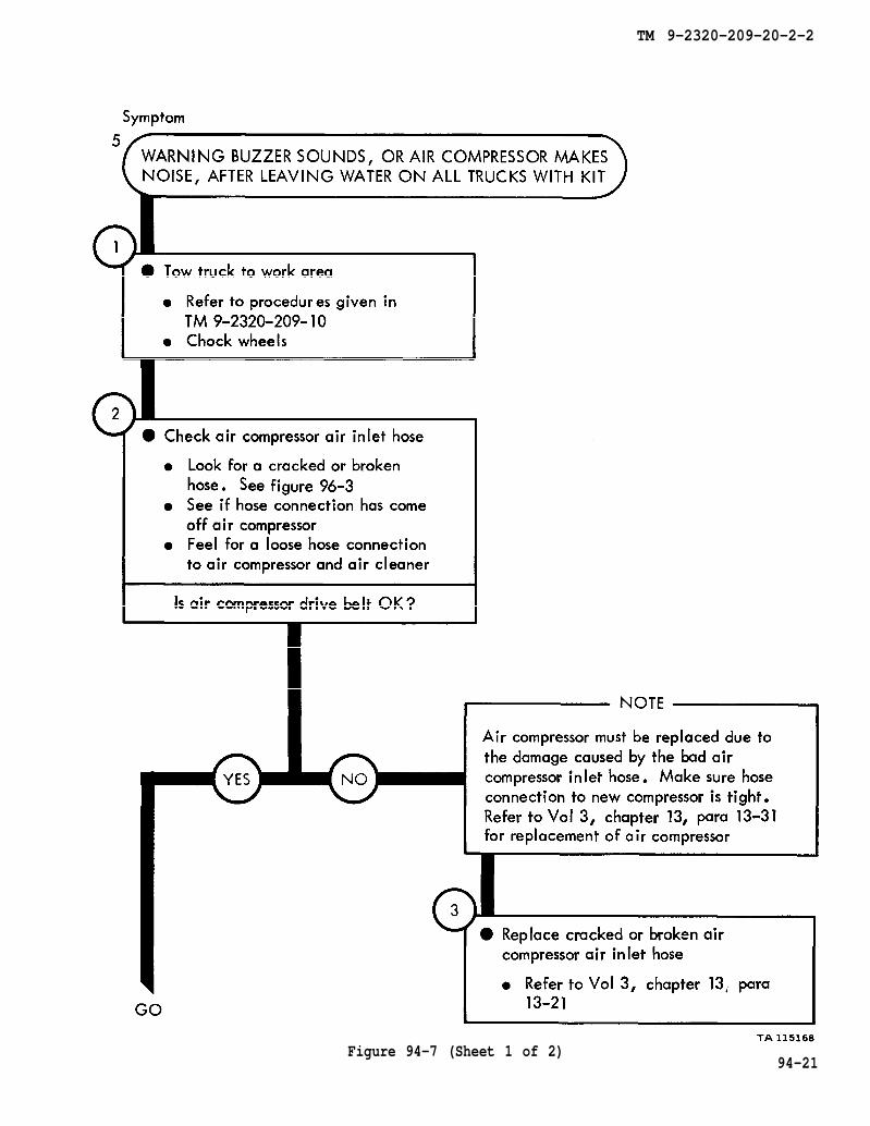
TM 9-2320-209-10
figure 96-3
chapter 13 para 13-31
chapter 13 para 13-21
TM 9-2320-209-20-2-2
Figure 94-7 (Sheet 1 of 2)94-21
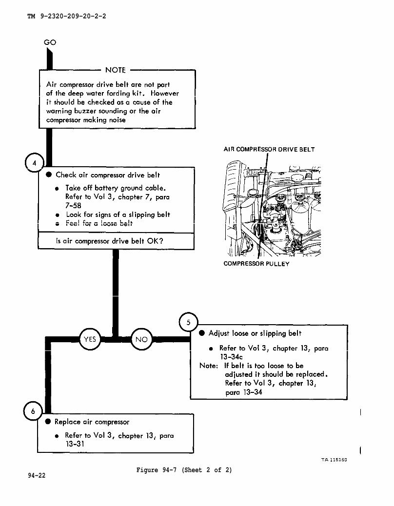
chapter 7 para7-58
chapter 13 para13-34c
chapter 13
para 13-34
chapter 13 para 13-31
TM 9-2320-209-20-2-2
Figure 94-7 (Sheet 2 of 2)94-22

TM 9-2320-209-20-2-2
CHAPTER 95
DEEP WATER FORDING KIT TROUBLESHOOTING SUMMARY
95-1. GENERAL. This chapter gives a summary of troubleshooting procedures givenin chapter 94 for the deep water fording kit.
95-2. PROCEDURES. The summary in this chapter covers all fault symptoms foundin the detailed troubleshooting procedures. Chapter 7 outlines a sample troubleshoot-ing procedure. The summary procedures are based on the “what-to-do” portions ofthe detailed procedures and do not include the “how-to-do-it” instructions. Warn-ings, cautions, and notes are given where needed.
95-1

TM 9-2320-209-20-2-2
DEEP WATER FORDING KIT ENGINE TROUBLESHOOTINGSUMMARY
Figure 95-1 (Sheet 1 of 3)
95-2
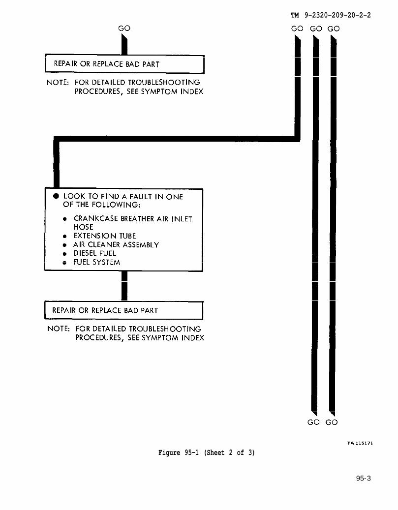
TM 9-2320-209-20-2-2
Figure 95-1 (Sheet 2 of 3)
95-3

TM 9-2320-209-20-2-2
Figure 95-1 (Sheet 3 of 3)
95-4
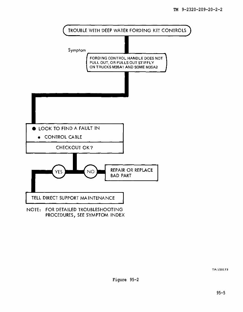
TM 9-2320-209-20-2-2
Figure 95-2
95-5
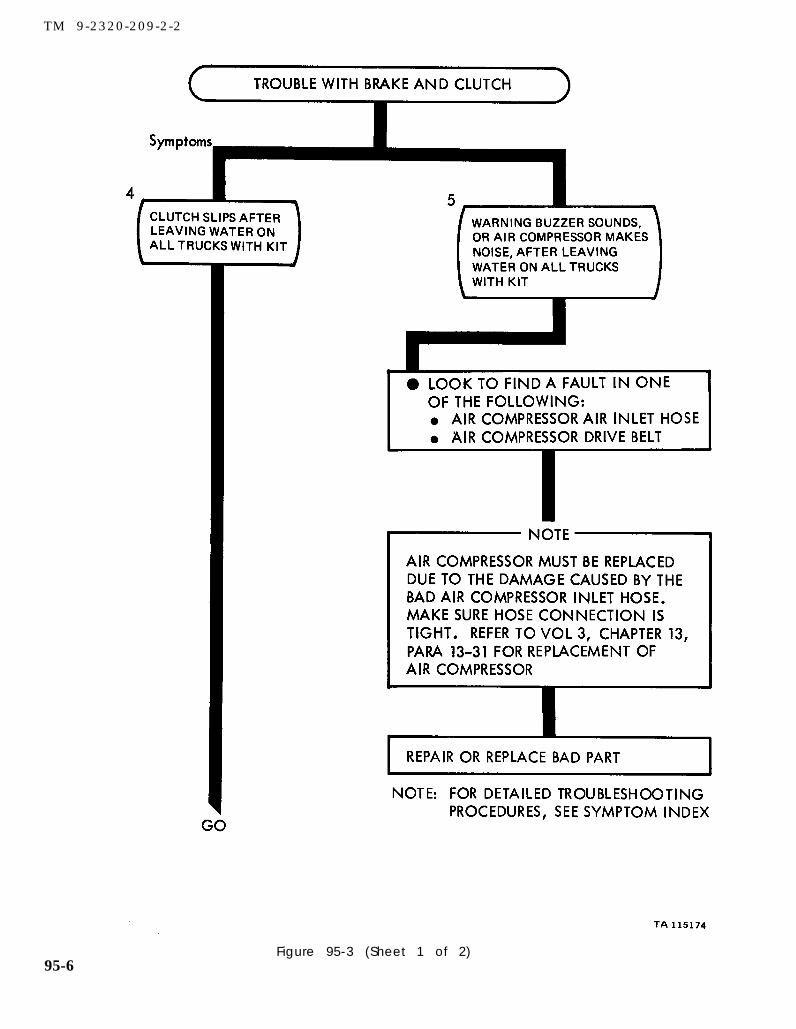
chapter 13
para 13-31
TM 9-2320-209-2-2
95-6Figure 95-3 (Sheet 1 of 2)

TM 9-2320-209-20-2-2
Figure 95-3 ( Sheet 2 of 2 )95-7/ ( 95-8 blank)

TM 9-2320-209-20-2-2
CHAPTER 96
DEEP WATER FORDING KIT SUPPORT DIAGRAMS
96-1. GENERAL. This chapter gives the diagrams you need when doing trouble-shooting procedures in chapter 94. Table 3-1 is a complete listing of all supportdiagrams used in this manual.
96-1
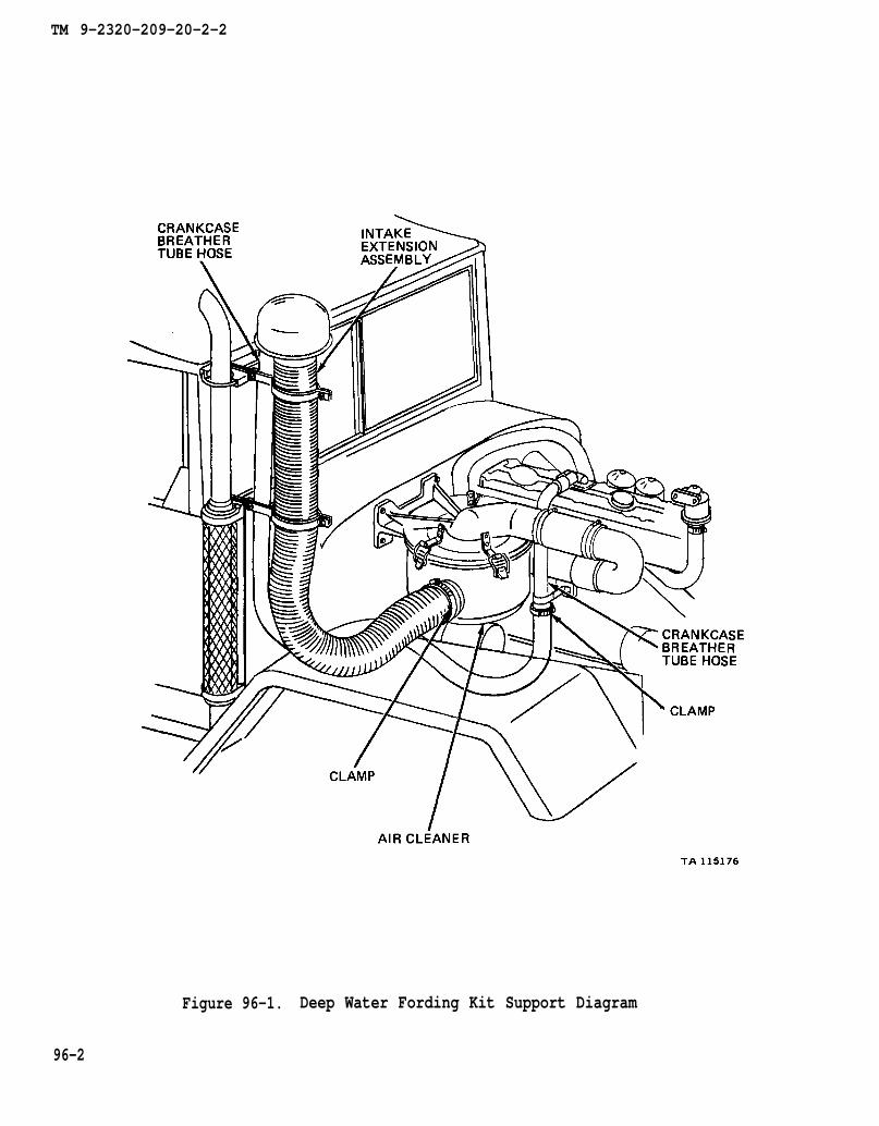
TM 9-2320-209-20-2-2
Figure 96-1. Deep Water Fording Kit Support Diagram
96-2
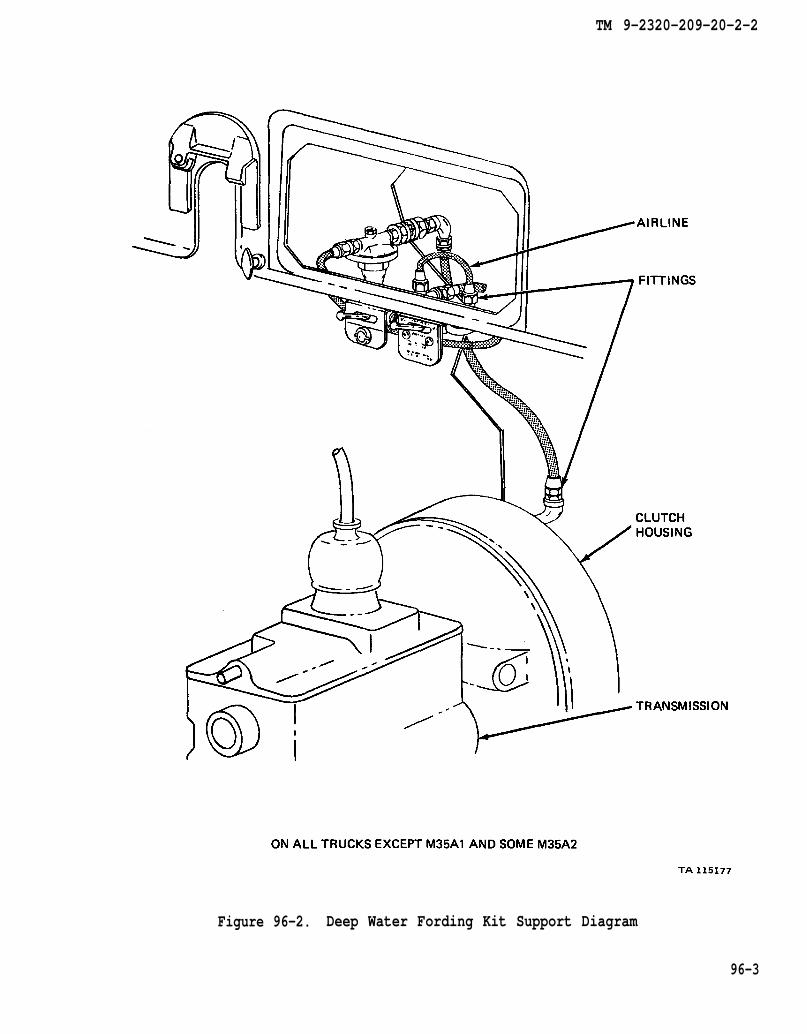
TM 9-2320-209-20-2-2
Figure 96-2. Deep Water Fording Kit Support Diagram
96-3
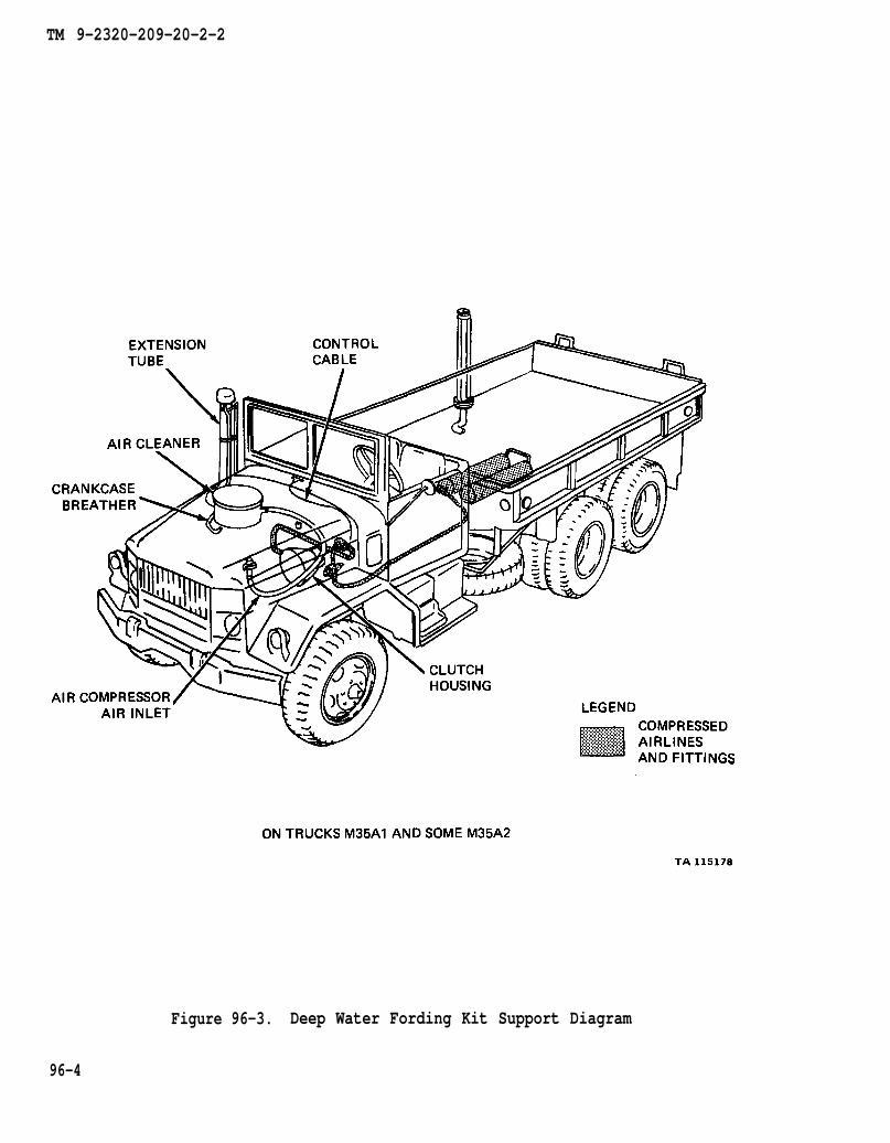
TM 9-2320-209-20-2-2
Figure 96-3. Deep Water Fording Kit Support Diagram
96-4
TM 9-2320-209-20-2-2
CHAPTER 97
DEEP WATER FORDING KIT CHECKOUT PROCEDURES
97-1. GENERAL. This chapter gives procedures for checking out the system aftertroubleshooting and repair have been done. Procedures are set up in flow chart formshowing the checkout steps in order and referring to the fault symptom index whenthe system does not check out.
97-1

Figure 97-1
TM 9-2320-209-10
TM 9-2320-209-10
TM 9-2320-209-10
TM 9-2320-209-10
TM 9-2320-209-10
TM 9-2320-209-20-2-2
DEEP WATER FORDING KIT CHECKOUT
97-2
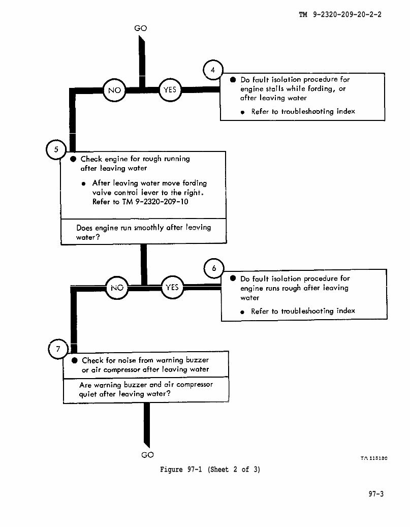
TM 9-2320-209-10
TM 9-2320-209-20-2-2
Figure 97-1 (Sheet 2 of 3)
97-3

TM 9-2320-209-10
TM 9-2320-209-10
TM 2320-209-10
TM 9-2320-209-20-2-2
Figure 97-1 (Sheet 3 of 3)
97-4

TM 9-2320-209-20-2-2
CHAPTER 98
NON-ELECTRICAL GAGES TROUBLESHOOTING
98-1. EQUIPMENT ITEMS COVERED. This chapter gives equipment troubleshootingprocedures for the non-electrical gages, for which there are authorized correctivemaintenance tasks at the organizational maintenance level.
98-2. EQUIPMENT ITEMS NOT COVERED. All equipment items for which correctivemaintenance is authorized at the organizational maintenance level are covered in thischapter.
98-1
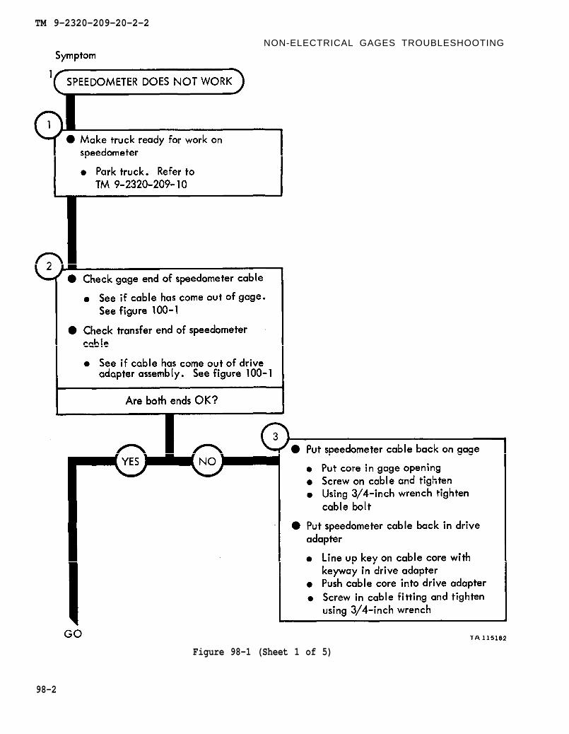
TM 9-2320-209-10
figure 100-1
figure 100-1
TM 9-2320-209-20-2-2
NON-ELECTRICAL GAGES TROUBLESHOOTING
Figure 98-1 (Sheet 1 of 5)
98-2

figure 100-1
chapter 22 para 22-4
figure 100-1
chapter 22 para 22-4
TM 9-2320-209-20-2-2
Figure 98-1 (Sheet 2 of 5)
98-3
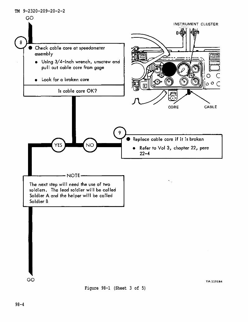
chapter 22 para 22-4
TM 9-2320-209-20-2-2
98-4
Figure 98-1 (Sheet 3 of 5)
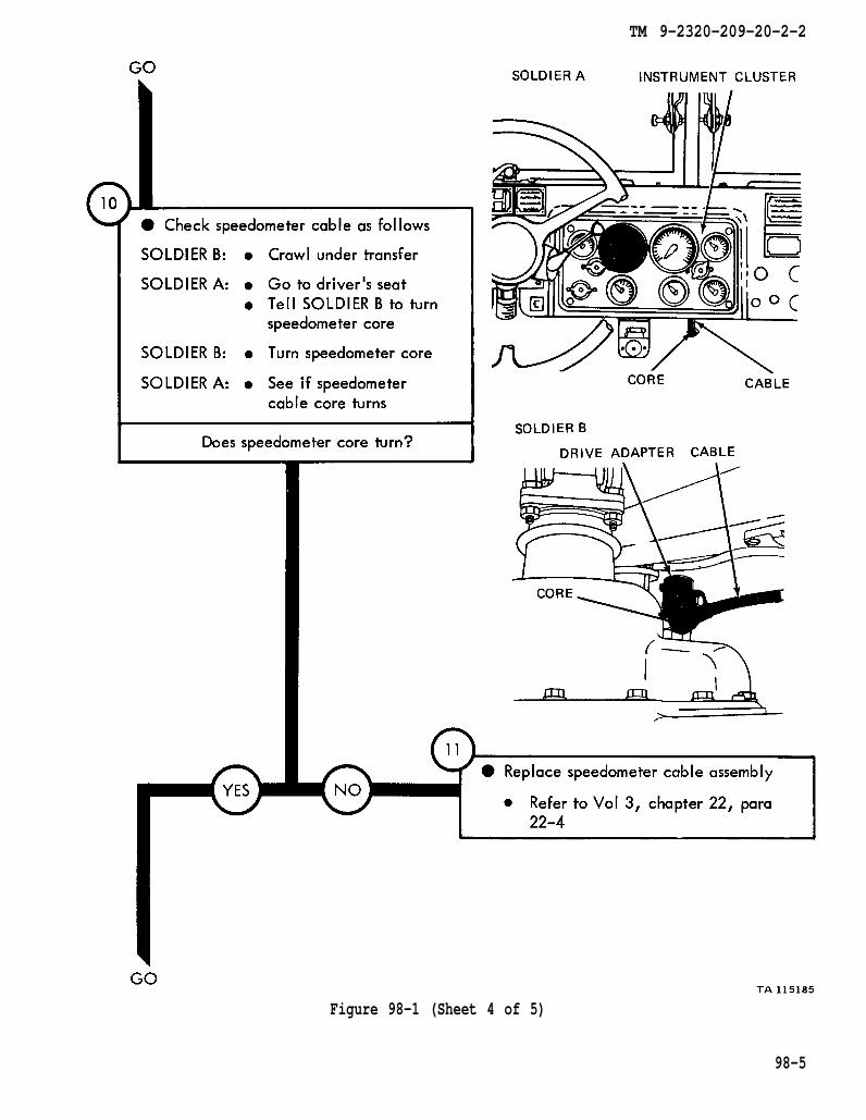
chapter 22 para 22-4
TM 9-2320-209-20-2-2
Figure 98-1 (Sheet 4 of 5)
98-5
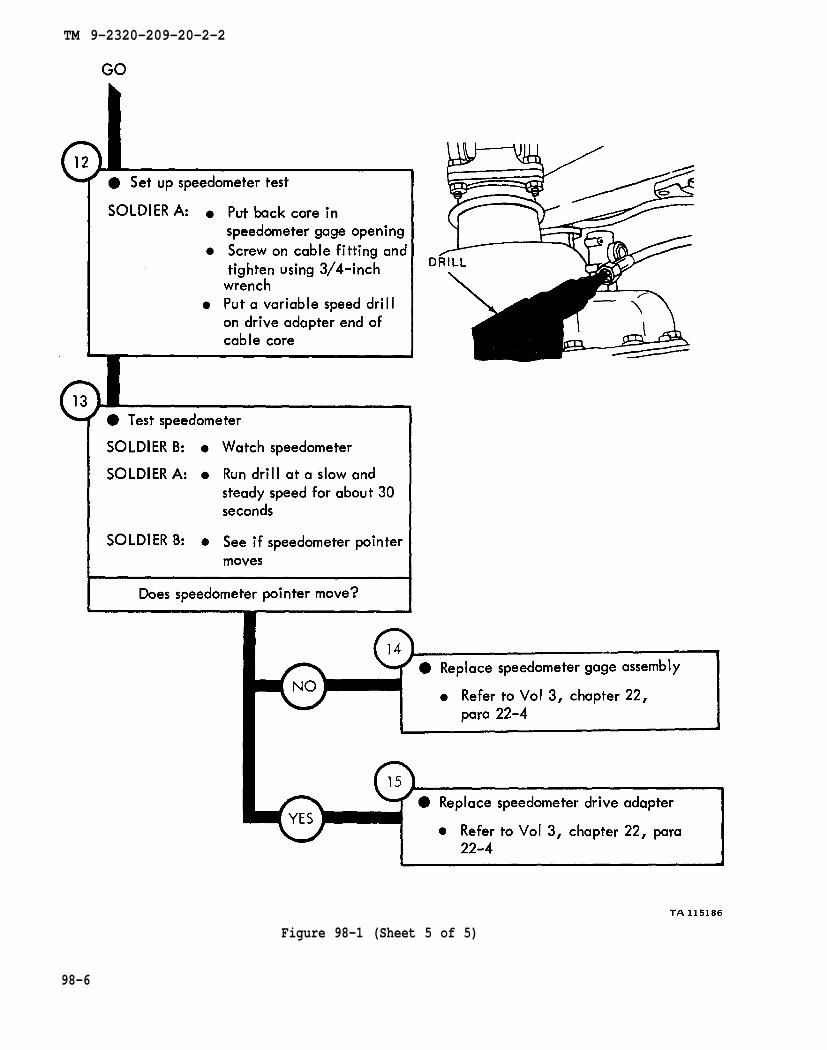
chapter 22 para 22-4
chapter 22
para 22-4
TM 9-2320-209-20-2-2
Figure 98-1 (Sheet 5 of 5)
98-6

TM 9-2320-209-10
figure 100-1
chapter 22 para 22-4
chapter 22 para 22-4
TM 9-2320-209-20-2-2
Figure 98-2 (Sheet 1 of 2)
98-7

chapter 22 para 22-4
TM 9-2320-209-20-2-2
Figure 98-2 (Sheet 2 of 2)
98-8

TM 9-2320-209-10
figure 100-1
chapter 22 para 22-4
TM 9-2320-209-20-2-2
Figure 98-3 (Sheet 1 of 3)
98-9
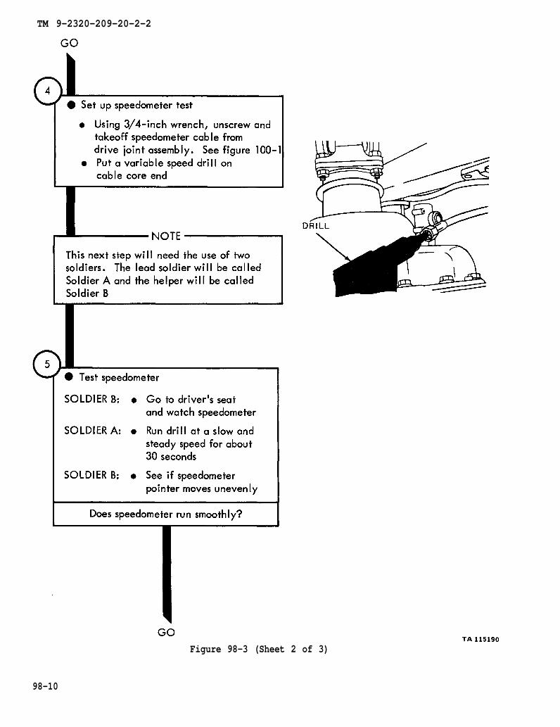
figure 100-1
TM 9-2320-209-20-2-2
Figure 98-3 (Sheet 2 of 3)
98-10
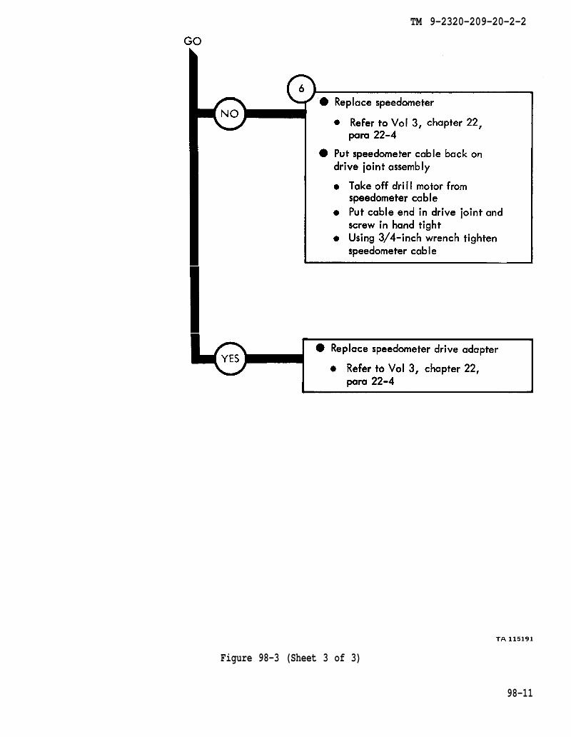
chapter 22
para 22-4
chapter 22
para 22-4
TM 9-2320-209-20-2-2
Figure 98-3 (Sheet 3 of 3)
98-11
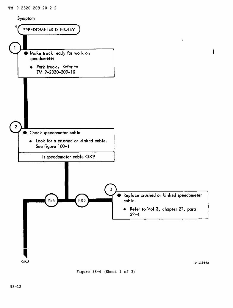
TM 9-2320-209-10
figure 100-1
chapter 22 para 22-4
TM 9-2320-209-20-2-2
Figure 98-4 (Sheet l of 3)
98-12
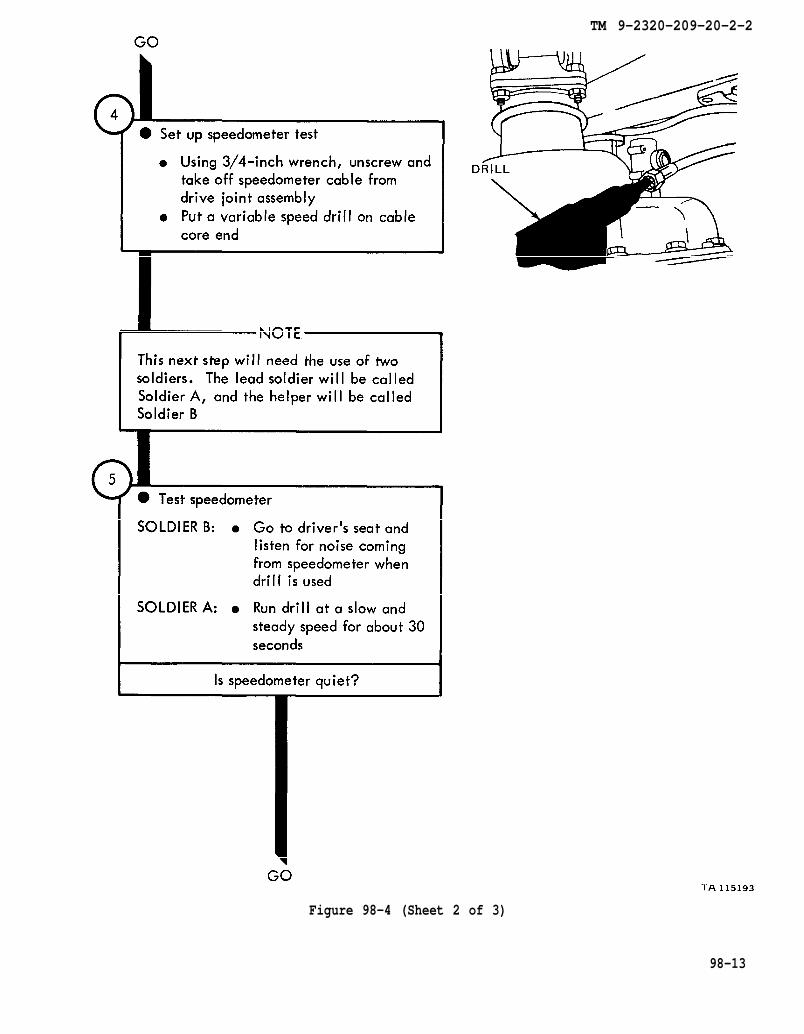
TM 9-2320-209-20-2-2
Figure 98-4 (Sheet 2 of 3)
98-13
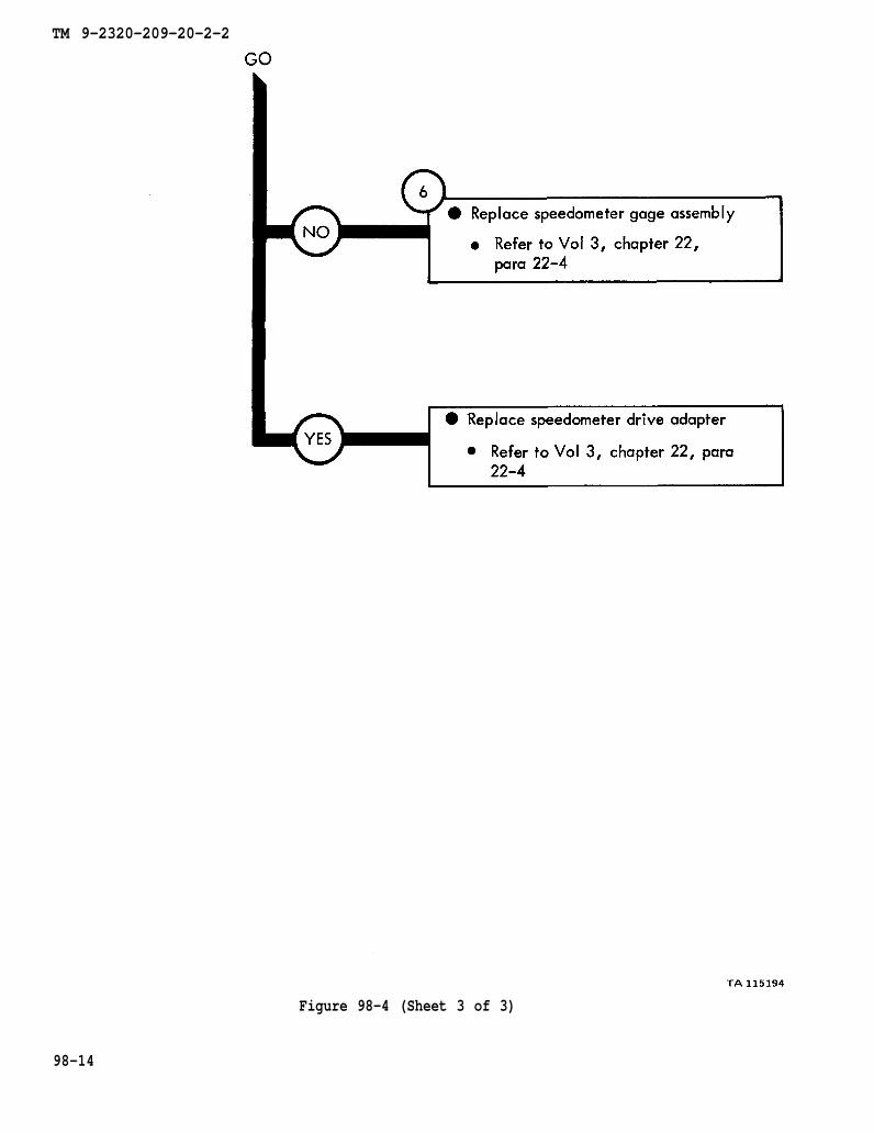
chapter 22
para 22-4
chapter 22 para 22-4
TM 9-2320-209-20-2-2
Figure 98-4 (Sheet 3 of 3)
98-14
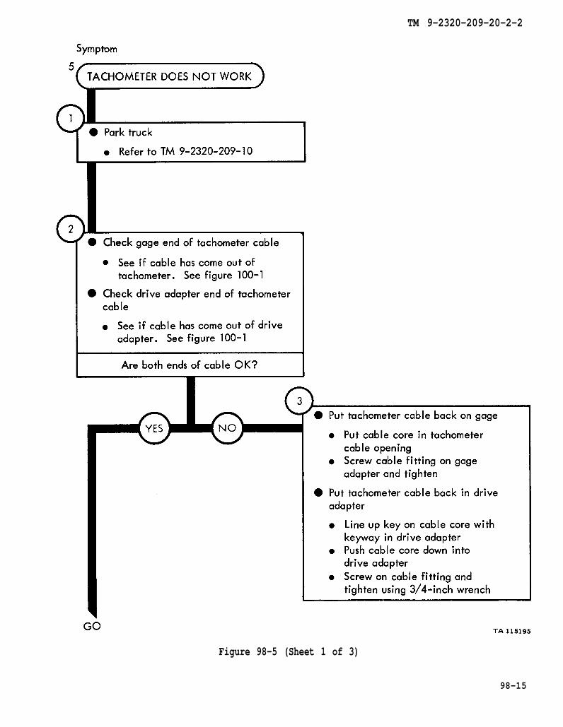
TM 9-2320-209-10
figure 100-1
figure 100-1
TM 9-2320-209-20-2-2
Figure 98-5 (Sheet 1 of 3)
98-15

figure 100-1
chapter 22 para 22-3
figure 100-1
TM 9-2320-209-20-2-2
Figure 98-5 (Sheet 2 of 3)
98-16

TM 9-2320-209-10
TM 9-2320-209-10
chapter 22
para 22-3
chapter 23
para 22-3
chapter 22
para 22-3
TM 9-2320-209-20-2-2
Figure 98-5 (Sheet 3 of 3)
98-17
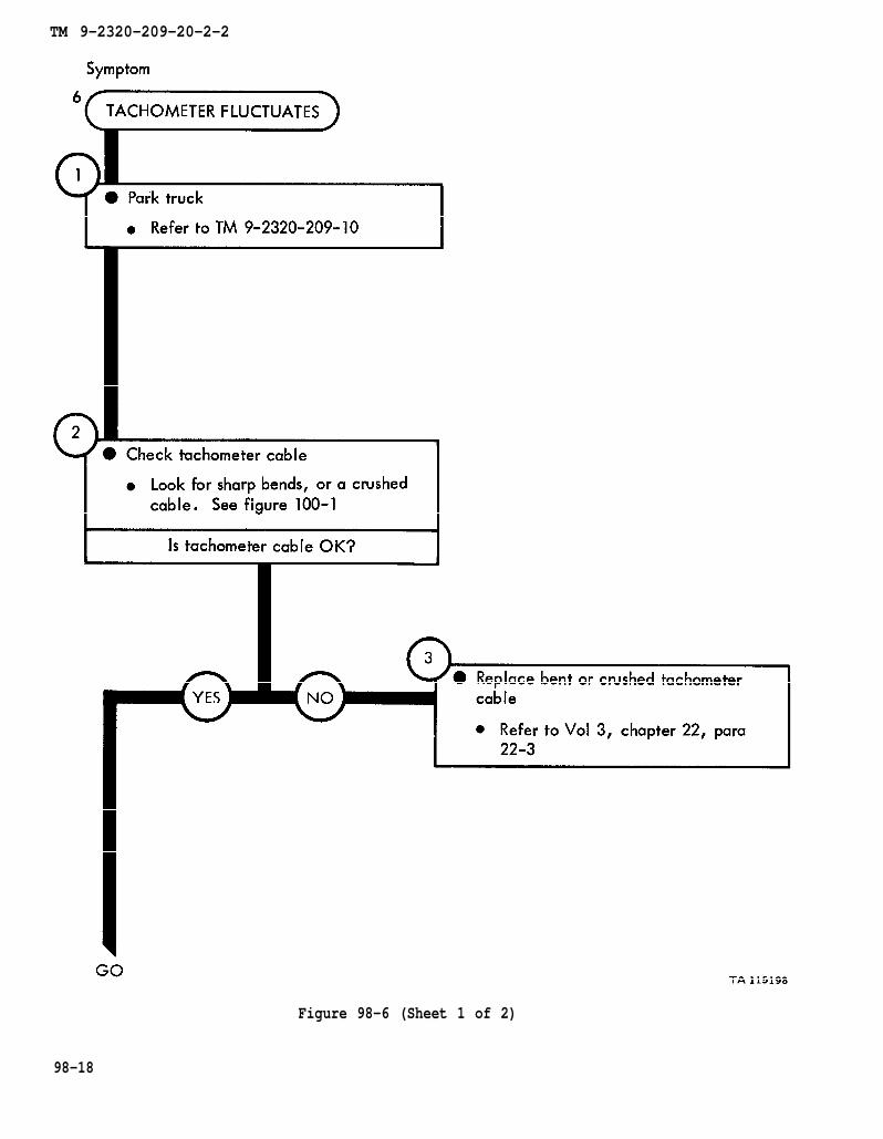
TM 9-2320-209-10
figure 100-1
chapter 22 para 22-3
TM 9-2320-209-20-2-2
Figure 98-6 (Sheet 1 of 2)
98-18
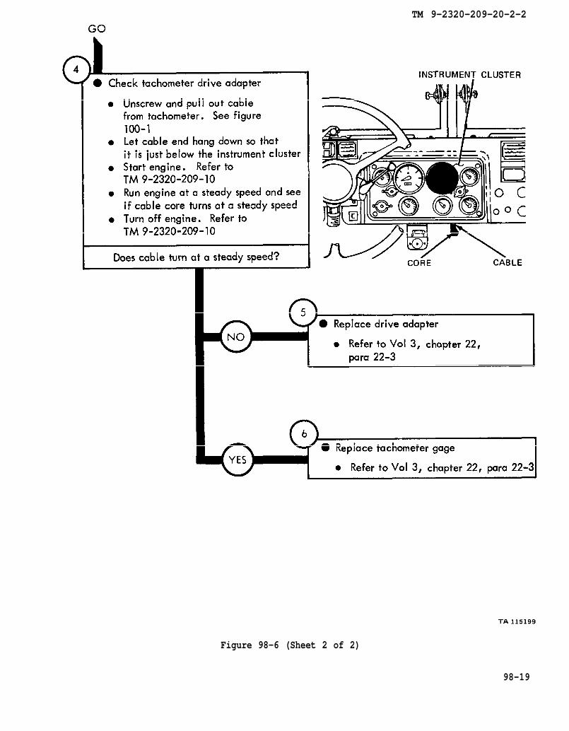
figure 100-1
TM 9-2320-209-10
TM 9-2320-209-10
chapter 22
para 22-3
chapter 22 para 22-3
TM 9-2320-209-20-2-2
Figure 98-6 (Sheet 2 of 2)
98-19

TM 9-2320-209-10
figure 100-1
chapter 22
para 22-3
TM 9-2320-209-20-2-2
Figure 98-7 (Sheet 1 of 3)
98-20

TM 9-2320-209-10
TM 9-2320-209-10
figure 100-1
TM 9-2320-209-10
TM 9-2320-209-10
TM 9-2320-209-20-2-2
Figure 98-7 (Sheet 2 of 3)
98-21

chapter 22
para 22-3
chapter 22
para 22-3
TM 9-2320-209-20-2-2
Figure 98-7 (Sheet 3 of 3)
98-22
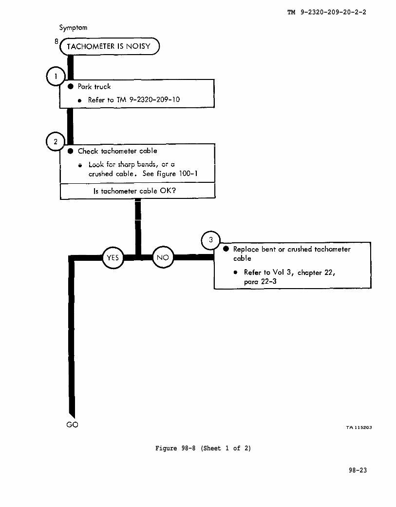
TM 9-2320-209-10
figure 100-1
chapter 22
para 22-3
TM 9-2320-209-20-2-2
Figure 98-8 (Sheet 1 of 2)
98-23

figure 100-1
TM 9-2320-209-10
TM 9-2320-209-10
chapter 22
para 22-3
chapter 22
para 22-3
TM 9-2320-209-20-2-2
Figure 98-8 (Sheet 2 of 2)
98-24
TM 9-2320-209-20-2-2
CHAPTER 99
NON-ELECTRICAL GAGES TROUBLESHOOTING SUMMARY
99-1. GENERAL. This chapter gives a summary of troubleshooting procedures givenin chapter 98 for the nonelectrical gages.
99-2. PROCEDURES. The summary in this chapter covers all fault symptoms foundin the detailed troubleshooting procedures. Chapter 7 outlines a sample troubleshoot-ing procedure. The summary procedures are based on the “what-to-do" portions ofthe detailed procedures and do not include the “how-to-do-it” instructions. Warn-ings, cautions, and notes are given where needed.
99-1
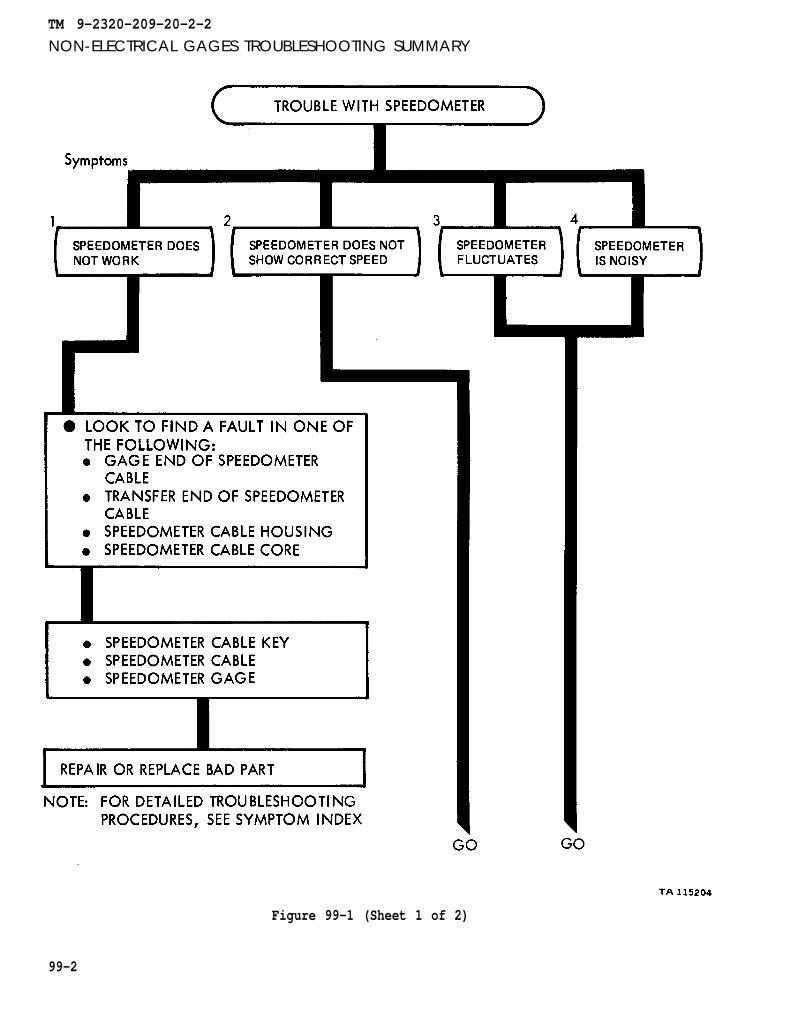
TM 9-2320-209-20-2-2
NON-ELECTRICAL GAGES TROUBLESHOOTING SUMMARY
Figure 99-1 (Sheet 1 of 2)
99-2
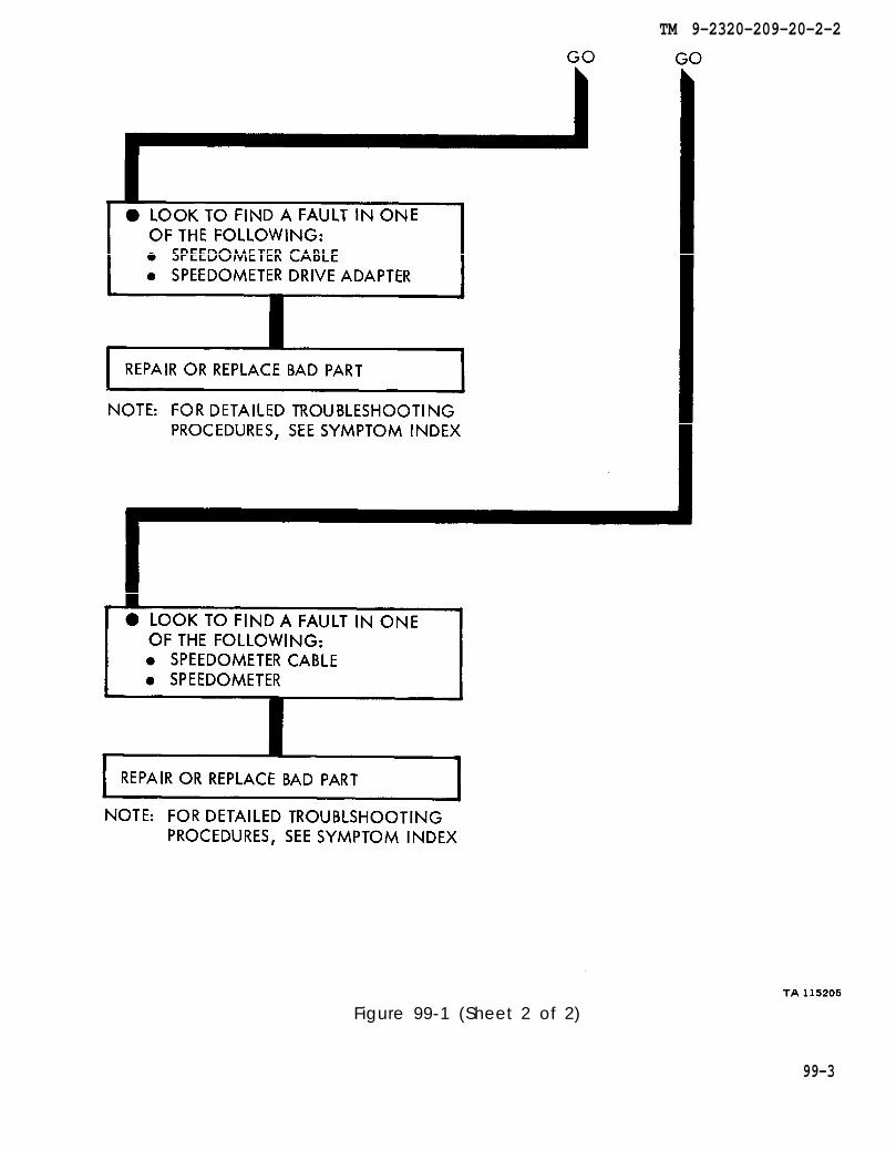
TM 9-2320-209-20-2-2
Figure 99-1 (Sheet 2 of 2)
99-3
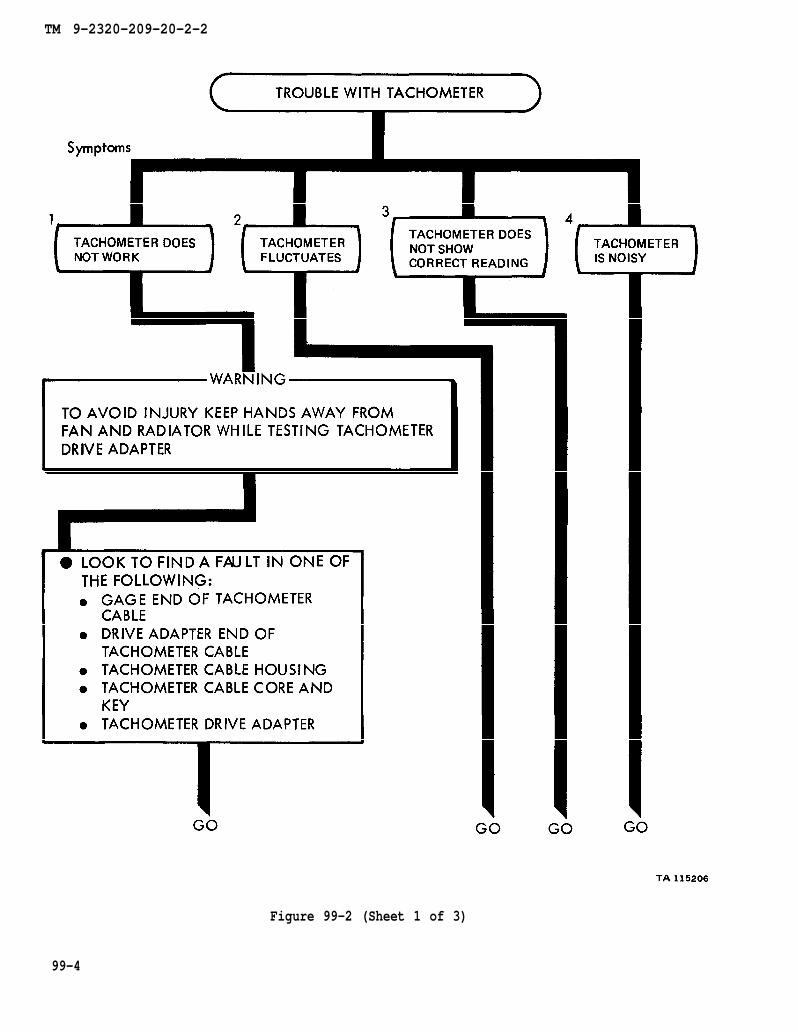
TM 9-2320-209-20-2-2
Figure 99-2 (Sheet 1 of 3)
99-4
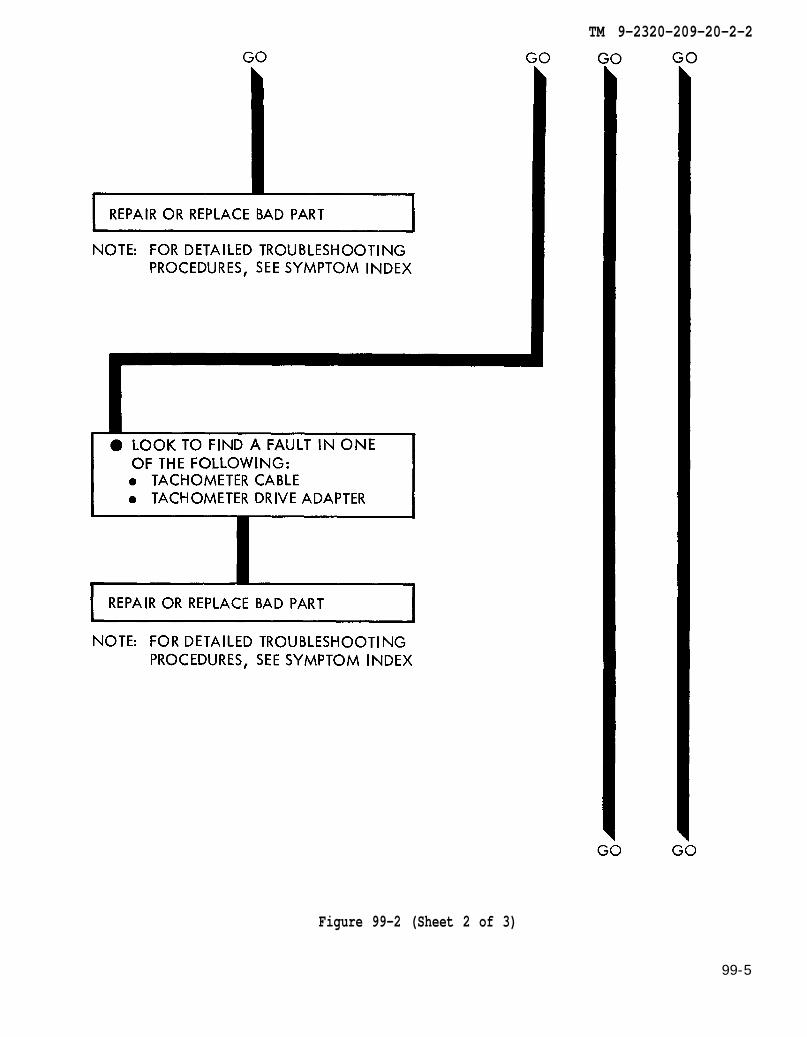
TM 9-2320-209-20-2-2
Figure 99-2 (Sheet 2 of 3)
99-5
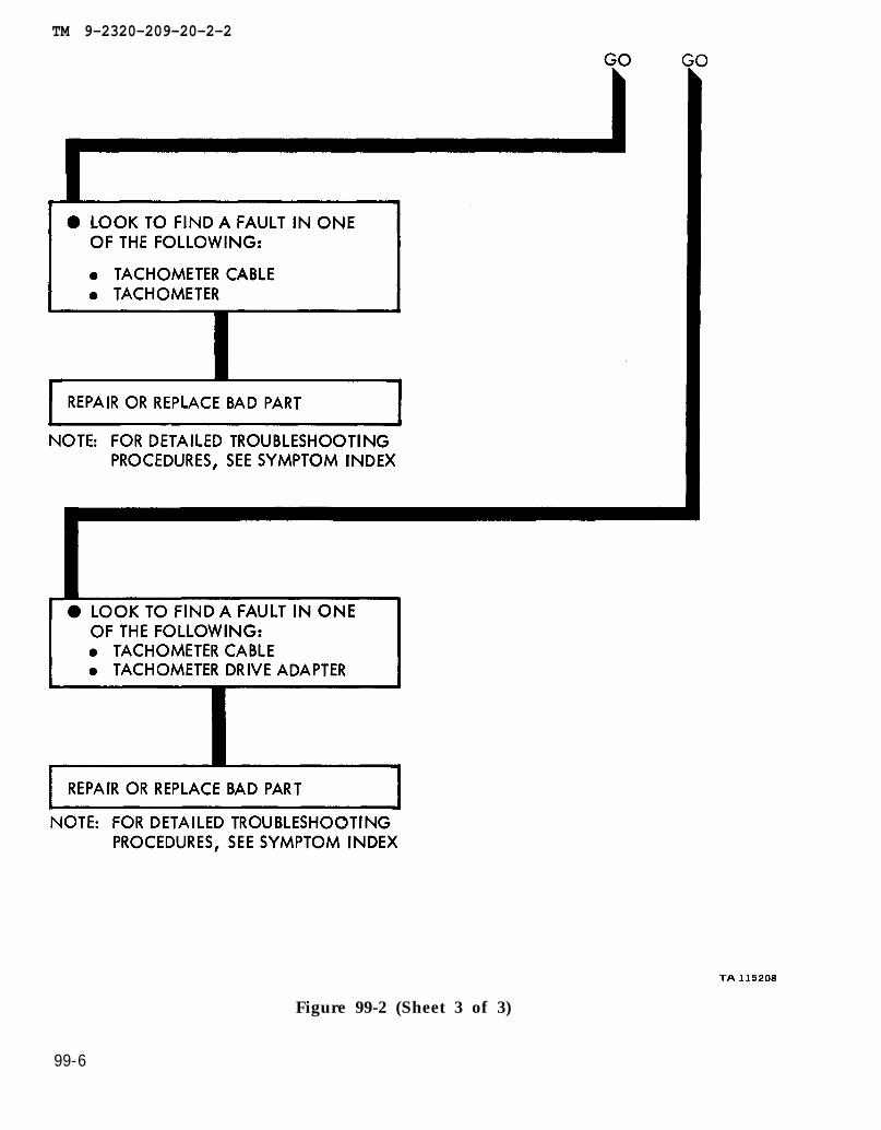
TM 9-2320-209-20-2-2
99-6
Figure 99-2 (Sheet 3 of 3)
TM 9-2320-209-20-2-2
CHAPTER 100
NON-ELECTRICAL GAGES SUPPORT DIAGRAMS
100-1. GENERAL. This chapter gives the diagrams you need when doing trouble-shooting procedures in chapter 98. Table 3-1 is a complete listing of all supportdiagrams used in this manual.
100-1
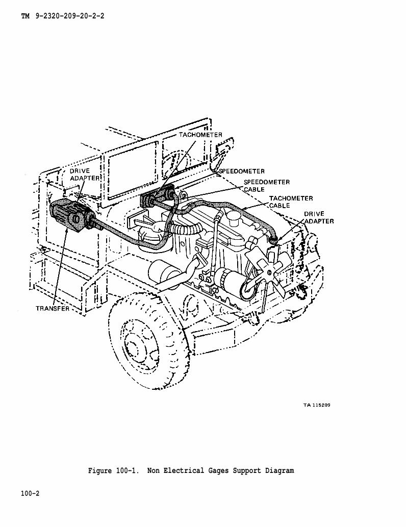
TM 9-2320-209-20-2-2
Figure 100-1. Non Electrical Gages Support Diagram
100-2

T M 9 - 2 3 2 0 - 2 0 9 - 2 0 - 2 - 2
By Order of the Secretaries of the Army and the Air Force:
Official:
J. C. PENNINGTONMajor General, United States
The Adjutant General
Official:
E. C. MEYERGeneral, United States Army
Chief of Staff
Army
LEW ALLEN, JR., General, USAFChief of Staff
VAN L. CRAWFORD, JR., Colonel, USAFDirector of Administration
Distribution:
To be distributed in accordance with DA Form 12-38, Organizational Maintenancerequirements for 2-l/2-Ton Truck Cargo, 2-l/2-Ton Truck Van, etc.
*U .S . GOVERNMENT PRINT ING OFF ICE: 1989 242 -451 /01764


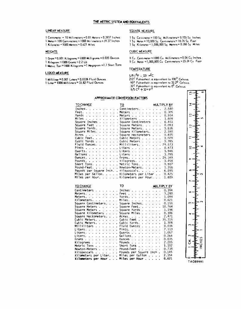

PIN: 048974-000