tm 5-601-1 utility systems terrorism countermeasures for ... · communications, computer,...
TRANSCRIPT

TM 5-602-1
TECHNICAL MANUAL
UTILITY SYSTEMS TERRORISM COUNTERMEASURES
FOR COMMAND, CONTROL, COMMUNICATIONS, COMPUTER, INTELLIGENCE, SURVEILLANCE, AND RECONNAISSANCE (C4ISR)
FACILITIES
APPROVED FOR PUBLIC RELEASE: DISTRIBUTION UNLIMITED
HEADQUARTERS, DEPARTMENT OF THE ARMY 21 FEBRUARY 2006

TM 5-602-1
REPRODUCTION AUTHORIZATION/RESTRICTIONS
This manual has been prepared by or for the Government and, except to the extent indicated below, is public property and not subject to copyright. Reprint or republication of this manual should include a credit substantially as follows: "Department of the Army, TM 5-602-1, Utility Systems Terrorism Countermeasures for Command, Control, Communications, Computer, Intelli-gence, Surveillance, and Reconnaissance (C4ISR) Facilities, 21 February 2006”

TM 5-602-1
i
Technical Manual HEADQUARTERS No. 5-602-1 DEPARTMENT OF THE ARMY Washington, DC, 21 February 2006
APPROVED FOR PUBLIC RELEASE: DISTRIBUTION IS UNLIMITED
UTILITY SYSTEMS TERRORISM COUNTERMEASURES FOR COMMAND, CONTROL, COMMUNICATIONS, COMPUTER,
INTELLIGENCE, SURVEILLANCE, AND RECONNAISSANCE (C4ISR) FACILITIES
CONTENTS Paragraph Page CHAPTER 1. INTRODUCTION Purpose....................................................................................................... 1-1 1-1 Scope.......................................................................................................... 1-2 1-1 References.................................................................................................. 1-3 1-1 Currency..................................................................................................... 1-4 1-1 CHAPTER 2. FUNDAMENTALS OF LIMITED VALNERABILITY DESIGN Background ................................................................................................ 2-1 2-1 Limitations of current practice ................................................................... 2-2 2-1 Limited vulnerability design concept......................................................... 2-3 2-1 Design basis threat ..................................................................................... 2-4 2-2 Example C4ISR facility ............................................................................. 2-5 2-2 Design criteria ............................................................................................ 2-6 2-4 Reliability criteria ...................................................................................... 2-7 2-5 Capacity criteria ......................................................................................... 2-8 2-5 Vulnerabilities............................................................................................ 2-9 2-6 Scalability .................................................................................................. 2-10 2-6 CHAPTER 3. ARCHITECTURAL AND STRUCTURAL SYSTEMS Architectural and structural systems design criteria .................................. 3-1 3-1 Applicable building codes and standards................................................... 3-2 3-1 Compartmentalization................................................................................ 3-3 3-2 Egress and circulation paths....................................................................... 3-4 3-2 Materials of construction ........................................................................... 3-5 3-3 CHAPTER 4. MECHANICAL SYSTEMS Mechanical design criteria ......................................................................... 4-1 4-1 Applicable codes and standards for mechanical systems........................... 4-2 4-1 System reliability ....................................................................................... 4-3 4-1 Plumbing distribution system configuration .............................................. 4-4 4-3 Plumbing system – automatic isolation and backfeed ............................... 4-5 4-5 Fire protection water and suppression systems.......................................... 4-6 4-5 Heating ventilation, and air-conditioning systems..................................... 4-7 4-6

TM 5-602-1
ii
Paragraph Page CONTENTS CHAPTER 5. ELECTRICAL SYSTEMS Electrical design criteria............................................................................. 5-1 5-1 Applicable electrical codes and standards.................................................. 5-2 5-1 Segregation and separation ........................................................................ 5-3 5-2 Protective device coordination................................................................... 5-4 5-2 Grounding and surge protection................................................................. 5-5 5-4 Physical installation ................................................................................... 5-6 5-4 Standby generation..................................................................................... 5-7 5-5 CHAPTER 6. CONTROL SYSTEMS Controls system design criteria .................................................................. 6-1 6-1 Applicable control systems codes and standards ....................................... 6-2 6-1 Agent detection .......................................................................................... 6-3 6-2 Distributed architecture.............................................................................. 6-4 6-3 Reliability................................................................................................... 6-5 6-3 Survivability............................................................................................... 6-6 6-6 Integration of functions.............................................................................. 6-7 6-7 CHAPTER 7. FIRE AND SECURITY SYSTEMS Fire and security system design criteria ..................................................... 7-1 7-1 General considerations............................................................................... 7-2 7-1 System layout............................................................................................. 7-3 7-1 Interface to SCADA systems ..................................................................... 7-4 7-2 CHAPTER 8. COMMISSIONING General commissioning.............................................................................. 8-1 8-1 Applicable commissioning codes and standards........................................ 8-2 8-1 Commissioning process ............................................................................. 8-3 8-2 CHAPTER 9. OPERATION AND MAINTENANCE General operations and maintenance ......................................................... 9-1 9-1 Applicable codes and standards ................................................................. 9-2 9-1 Maintenance scheduling............................................................................. 9-3 9-1 Periodic testing........................................................................................... 9-4 9-1 Spare parts stocking ................................................................................... 9-5 9-2 Disaster recovery........................................................................................ 9-6 9-2 APPENDIX A REFERENCES..................................................................................... A-1 APPENDIX B LIST OF ACRONYMS AND ABBREVIATIONS ............................. B-1 APPENDIX C AVAILABILITY ANALYSIS OF EXAMPLE FACILITY SYSTEMS C-1 APPENDIX D EXAMPLE OF UTILITY CAPACITY CALCULATION.................. D-1 APPENDIX E DISASTER RECOVERY SUGGESTED PRIMARY CONTACT MATRIX E-1 GLOSSARY .................................................................................................................... G-1

TM 5-602-1
iii
CONTENTS
LIST OF TABLES
Number Title Page 2-1 Example facility space classification ......................................................... 2-4 5-1 Features of utility-grade and commercial-grade equipment ...................... 5-1
LIST OF FIGURES
Number Title Page 2-1 Example facility first floor plan ................................................................. 2-3 2-2 Example facility second floor plan ............................................................ 2-3 4-1 Scaled peripheral zone support of the command center............................. 4-3 4-2 Zoned utility connections........................................................................... 4-4 4-3a Dry side schematic plan view of HVAC system........................................ 4-7 4-3b Wet side schematic plan view of HVAC system ....................................... 4-8 4-3c Wet side schematic diagram of a typical mechanical room....................... 4-9 4-4 Normal pressurization ................................................................................ 4-10 4-5 Emergency pressurization .......................................................................... 4-11 5-1 Example facility single-line diagram ......................................................... 5-3 6-1 SCADA system architecture for the example facility................................ 6-4 6-2 Ethernet switches in self-healing ring topology......................................... 6-5 7-1 Fire and security system architecture......................................................... 7-2

TM 5-602-1
1-1
CHAPTER 1 INTRODUCTION
1-1. Purpose The purpose of this technical manual (TM) is to provide guidance for facility managers and engineers in applying the principles of limited vulnerability design (LVD) to the utility systems for command, control, communications, computer, intelligence, surveillance, and reconnaissance (C4ISR) facilities. It will also provide generic guidance to agencies responsible for the planning, design, and installation of such sys-tems in C4ISR facilities. The utility systems for C4ISR facilities include those providing heating, cool-ing, ventilation, water, sanitation, and electrical service to the mission-critical loads within the facilities as well as their associated control systems 1-2. Scope The LVD model is a set of principles to apply in designing a C4ISR facility that is compartmentalized and provides multiple service pathways for all utilities to the critical load as protection against an internal terrorist attack intended to interrupt the mission. a. This TM includes an example facility floor plan, which is the basis for discussion of the application of the LVD principles to the utility systems. The primary focus of this TM is the mechanical and electri-cal utility systems and their controls. b. This TM addresses utility system topics only as they are affected by or require different considera-tion due to the application of the LVD concept. Other aspects of utility system design that are addressed by industry standards, other TMs, or United States Department of Defense (DoD) documents are not re-peated in this TM. Similarly, examples include only discussion of those aspects of system design consid-ered relevant to LVD and may not show other features required by industry codes and standards. 1-3. References Appendix A, References, contains a complete list of the sources cited in this TM. Planning, design, in-stallation, and commissioning of utility systems should always be based on the most current relevant edi-tion of the standards listed as references. Where the recommendations of this TM and the referenced standards differ, the more stringent requirement should be followed. 1-4. Currency The LVD concept is in part intended to isolate and prevent the spread of chemical, biological, or radio-logical (CBR) and other agents for which detection and mitigation technology is rapidly evolving. This TM discusses agent detection and mitigation in general but does not recommend specific sensor types or filtration techniques because the technology is expected to advance faster than this TM will be updated. It is also possible that additional detection technology will be developed for threats such as explosives, for which no practical wide-area detection method exists today. Equipment and systems intended for threat detection and response should always be selected from the most current proven technologies.
TM 5-602-1
2-1
CHAPTER 2 FUNDAMENTALS OF LIMITED VULNERABILITY DESIGN
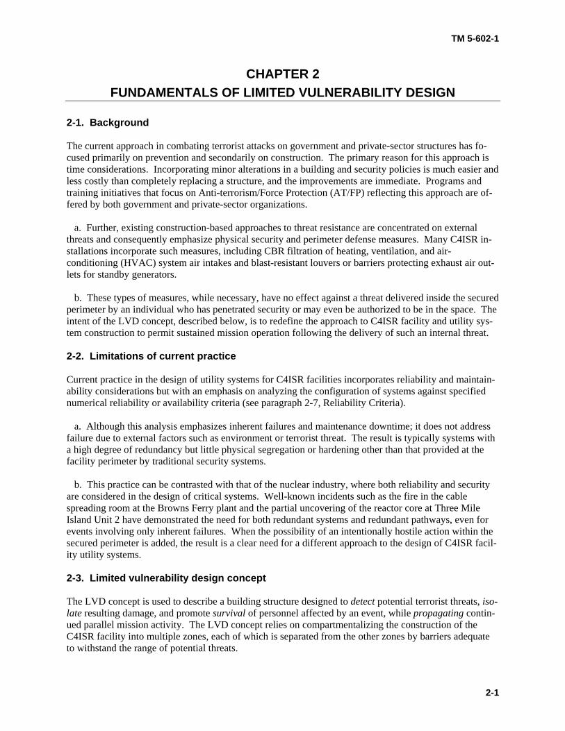
2-1. Background The current approach in combating terrorist attacks on government and private-sector structures has fo-cused primarily on prevention and secondarily on construction. The primary reason for this approach is time considerations. Incorporating minor alterations in a building and security policies is much easier and less costly than completely replacing a structure, and the improvements are immediate. Programs and training initiatives that focus on Anti-terrorism/Force Protection (AT/FP) reflecting this approach are of-fered by both government and private-sector organizations. a. Further, existing construction-based approaches to threat resistance are concentrated on external threats and consequently emphasize physical security and perimeter defense measures. Many C4ISR in-stallations incorporate such measures, including CBR filtration of heating, ventilation, and air-conditioning (HVAC) system air intakes and blast-resistant louvers or barriers protecting exhaust air out-lets for standby generators. b. These types of measures, while necessary, have no effect against a threat delivered inside the secured perimeter by an individual who has penetrated security or may even be authorized to be in the space. The intent of the LVD concept, described below, is to redefine the approach to C4ISR facility and utility sys-tem construction to permit sustained mission operation following the delivery of such an internal threat.
2-2. Limitations of current practice Current practice in the design of utility systems for C4ISR facilities incorporates reliability and maintain-ability considerations but with an emphasis on analyzing the configuration of systems against specified numerical reliability or availability criteria (see paragraph 2-7, Reliability Criteria). a. Although this analysis emphasizes inherent failures and maintenance downtime; it does not address failure due to external factors such as environment or terrorist threat. The result is typically systems with a high degree of redundancy but little physical segregation or hardening other than that provided at the facility perimeter by traditional security systems. b. This practice can be contrasted with that of the nuclear industry, where both reliability and security are considered in the design of critical systems. Well-known incidents such as the fire in the cable spreading room at the Browns Ferry plant and the partial uncovering of the reactor core at Three Mile Island Unit 2 have demonstrated the need for both redundant systems and redundant pathways, even for events involving only inherent failures. When the possibility of an intentionally hostile action within the secured perimeter is added, the result is a clear need for a different approach to the design of C4ISR facil-ity utility systems. 2-3. Limited vulnerability design concept The LVD concept is used to describe a building structure designed to detect potential terrorist threats, iso-late resulting damage, and promote survival of personnel affected by an event, while propagating contin-ued parallel mission activity. The LVD concept relies on compartmentalizing the construction of the C4ISR facility into multiple zones, each of which is separated from the other zones by barriers adequate to withstand the range of potential threats.

TM 5-602-1
2-2
a. This approach is used along with redundancy of mechanical and electrical systems to accomplish two objectives: The first is to limit the effect of an event to the compartment, or zone, in which it occurs, al-lowing continued mission operation in other zones. The other objective is to prevent an event in any zone of the building from interrupting utility service to the most critical mission, such as a central command center. b. For example, if a biological agent were introduced into the HVAC system of a structure, sensing and controls capable of detecting the agent would operate the HVAC system to contain the agent within the zone of introduction. If an explosion were to occur within a zone and disable utility service equipment in that zone, the mission in other zones would be unaffected and sources in other zones would continue to provide uninterrupted service to the most critical space.
2-4. Design basis threat The range of potential threats for application of the LVD concept encompasses generally any weapon or agent that can be hand-carried into the facility by an individual and deployed or released inside the se-cured perimeter; it also includes any damaging action that can be taken by an individual inside the facil-ity, such as manually discharging a wet sprinkler system over computer equipment. a. There are many different types of conventional threats such as the ones listed below as well as others not yet defined or developed: (1) Firearm discharge (2) Explosion (3) Fire (4) Flood (5) Toxic gas or liquid (chemical) (6) Infectious agent (biological) (7) Ionizing radiation source (radiological) (8) Electromagnetic fields (9) Software intrusion b. The design basis threat should be defined specifically for each facility based on a risk and vulnerabil-ity assessment that considers mission, geographic location, and other factors. c. With respect to structural threats such as explosion and fire, this TM is not intended to quantitatively define the threat level or to provide guidance in the design of structures to resist specific threats. It is as-sumed that other applicable standards will be used to determine the design basis threat for a specific facil-ity and that the structural features separating zones of the facility will be designed to withstand the threat according to those standards. This TM focuses on the design of the utility systems in unaffected zones to detect, respond to, and survive the threat.

TM 5-602-1
2-3
2-5. Example C4ISR facility Figures 2-1 and 2-2 present floor plans of an example C4ISR facility to illustrate the application of LVD concepts to the design of utility systems. This example is not intended to limit either the size or the mis-sion character of potential facilities but simply to assist in explaining the application of design concepts discussed in this TM.
Figure 2-1. Example facility first floor plan
Figure 2-2. Example facility second floor plan

TM 5-602-1
2-4
a. The example facility is a two-story structure of approximately 35,000 gross square feet (GSF) of floor plan, divided into five mission zones and containing four classes of secure space, as defined in table 2-1. The outer ring corridor provides a perimeter barrier for the internal space and a means of moving be-tween zones without requiring penetration of internal barriers. This corridor also provides for accessibil-ity and emergency egress as required by building codes. Public access to the building is through an entry checkpoint outside the perimeter of this corridor.
Table 2-1. Example facility space classification
Class Area Function Security Level 0 Entry Checkpoint Access and Screening Low 1 Perimeter Corridor Circulation and Egress Medium 2 Zones 1 through 4 Mission Support High 3 Zone 5 (Command Center) Mission Critical Highest
b. The peripheral zones (1 through 4) immediately inside the ring corridor contain less critical mission activities and support activities for Zone 5, which is a command center in this example. Each peripheral zone includes mechanical and electrical equipment space for utility service to that zone. Zone 5 repre-sents the most critical space and receives a portion of its utility requirements from each of the peripheral zones. 2-6. Design criteria The principles of LVD described in this TM are intended to supplement, not replace, existing guidelines for the design of utility systems for C4ISR facilities. a. The primary references for general design criteria are: (1) TM 5-601, Supervisory Control and Data Acquisition Systems for Command, Control, Commu-nications, Computer, Intelligence, Surveillance, and Reconnaissance (C4ISR) Facilities. (2) TM 5-691, Utility Systems Design Requirements for Command, Control, Communications, Com-puter, Intelligence, Surveillance, and Reconnaissance (C4ISR) Facilities. (3) TM 5-692-2, Maintenance of Mechanical and Electrical Equipment at Command, Control, Com-munications, Computer, Intelligence, Surveillance, and Reconnaissance (C4ISR) Facilities – System De-sign Features. (4) TM 5-698-1, Reliability/Availability of Electrical & Mechanical Systems for Command, Control, Communications, Computer, Intelligence, Surveillance, and Reconnaissance (C4ISR) Facilities. b. The application of the LVD concept generates the following additional utility system design criteria and assumptions applicable to the example facility: (1) Mission activities require the entire facility to be self-supporting in the absence of external utili-ties for a specified mission time. This may dictate substantial internal storage of fuel for boilers and gen-erators and of water for plumbing systems and cooling system makeup. This requirement does not apply to utilities needed only for life safety functions, such as fire protection water.

TM 5-602-1
2-5
(2) The mission-critical space (Zone 5) must be supplied by utilities from enough sources to meet the reliability criteria, with segregation of pathways adequate to ensure survival of the required capacity. (3) The mission-critical space must have fast-acting automatic systems to isolate the connections to a peripheral zone when an event occurs. This will prevent introduction of an agent to the command center through ductwork, draining of the command center chilled water system through ruptured zone piping, and similar impacts. (4) Activities in the mission support space (Zones 1 through 4) are duplicated, if necessary, by paral-lel activities in other zones and thus do not require redundant utility services. (5) There is no need to maintain partial mission activity or survivability within a zone where an event occurs. Systems intended strictly to promote survival of personnel or limitation of damage within a zone are recommended but are considered to be in addition to and not part of the scope of the LVD concept. 2-7. Reliability criteria In general, the utility systems serving each zone of a facility that incorporates the LVD concept should meet the target reliability, availability, and maintainability (RAM) criteria specified for the mission activ-ity within that zone. RAM criteria and various modeling and analysis methodologies applicable to C4ISR facilities are described in detail in TM 5-698-1. As design proceeds, systems should be modeled and RAM analysis performed in accordance with TM 5-698-1 to verify that all criteria are met. a. Regardless of the numerical RAM criteria applied, the minimum level of redundancy for utility ser-vices from the peripheral zones to the command center should be N+2, where N is the number of sources required to meet the load. This ensures that with one source out of service for maintenance, an event af-fecting another source will not result in interruption of service to the command center. b. For the example facility, with four peripheral zones available to supply utilities to the command cen-ter, requiring that the command center be able to operate at full mission capacity from two of the four zones (N=2) while providing connections from all four produces an N+2 system. The N+2 mechanical and electrical utility systems described in subsequent chapters of this TM have been analyzed and shown to provide an availability of utilities to the command center of "six nines," or 99.9999 percent, generally considered acceptable for mission-critical spaces. The report of this analysis is provided in appendix C, Reliability Analysis of Example Systems.
2-8. Capacity criteria The utility systems in each zone should be sized to meet the peak demand of that zone plus the portion of the command center load determined by applying the above reliability criteria to the number of sources. For the example facility, with N+2 redundancy, each zone system would be sized at 100 percent of the zone load plus 50 percent of the command center load as a minimum. a. Limiting the complexity of the utility systems within the command center zone may dictate higher capacities in the zone sources than dictated by redundancy alone. For example, an electrical system within the command center that uses four 50 percent sources may require more complex switching and controls than one that uses four 100 percent sources. Plan for future growth when sizing equipment. b. Appendix D, Example of Utility Capacity Calculation, demonstrates how the required capacity is developed for the systems in the example facility.
TM 5-602-1
2-6
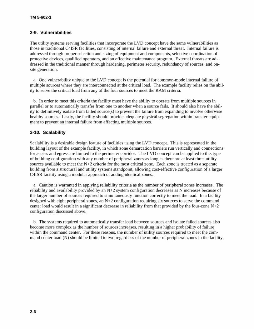
2-9. Vulnerabilities The utility systems serving facilities that incorporate the LVD concept have the same vulnerabilities as those in traditional C4ISR facilities, consisting of internal failure and external threat. Internal failure is addressed through proper selection and sizing of equipment and components, selective coordination of protective devices, qualified operators, and an effective maintenance program. External threats are ad-dressed in the traditional manner through hardening, perimeter security, redundancy of sources, and on-site generation. a. One vulnerability unique to the LVD concept is the potential for common-mode internal failure of multiple sources where they are interconnected at the critical load. The example facility relies on the abil-ity to serve the critical load from any of the four sources to meet the RAM criteria. b. In order to meet this criteria the facility must have the ability to operate from multiple sources in parallel or to automatically transfer from one to another when a source fails. It should also have the abil-ity to definitively isolate from failed source(s) to prevent the failure from expanding to involve otherwise healthy sources. Lastly, the facility should provide adequate physical segregation within transfer equip-ment to prevent an internal failure from affecting multiple sources. 2-10. Scalability Scalability is a desirable design feature of facilities using the LVD concept. This is represented in the building layout of the example facility, in which zone demarcation barriers run vertically and connections for access and egress are limited to the perimeter corridor. The LVD concept can be applied to this type of building configuration with any number of peripheral zones as long as there are at least three utility sources available to meet the N+2 criteria for the most critical zone. Each zone is treated as a separate building from a structural and utility systems standpoint, allowing cost-effective configuration of a larger C4ISR facility using a modular approach of adding identical zones. a. Caution is warranted in applying reliability criteria as the number of peripheral zones increases. The reliability and availability provided by an N+2 system configuration decreases as N increases because of the larger number of sources required to simultaneously function correctly to meet the load. In a facility designed with eight peripheral zones, an N+2 configuration requiring six sources to serve the command center load would result in a significant decrease in reliability from that provided by the four-zone N+2 configuration discussed above. b. The systems required to automatically transfer load between sources and isolate failed sources also become more complex as the number of sources increases, resulting in a higher probability of failure within the command center. For these reasons, the number of utility sources required to meet the com-mand center load (N) should be limited to two regardless of the number of peripheral zones in the facility.
TM 5-602-1
3-1
CHAPTER 3 ARCHITECTURAL AND STRUCTURAL SYSTEMS
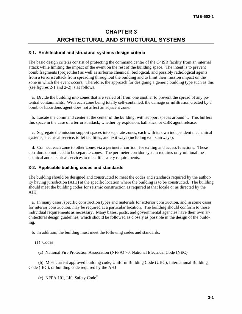
3-1. Architectural and structural systems design criteria The basic design criteria consist of protecting the command center of the C4ISR facility from an internal attack while limiting the impact of the event on the rest of the building space. The intent is to prevent bomb fragments (projectiles) as well as airborne chemical, biological, and possibly radiological agents from a terrorist attack from spreading throughout the building and to limit their mission impact on the zone in which the event occurs. Therefore, the approach for designing a generic building type such as this (see figures 2-1 and 2-2) is as follows: a. Divide the building into zones that are sealed off from one another to prevent the spread of any po-tential contaminants. With each zone being totally self-contained, the damage or infiltration created by a bomb or hazardous agent does not affect an adjacent zone. b. Locate the command center at the center of the building, with support spaces around it. This buffers this space in the case of a terrorist attack, whether by explosion, ballistics, or CBR agent release. c. Segregate the mission support spaces into separate zones, each with its own independent mechanical systems, electrical service, toilet facilities, and exit ways (including exit stairways). d. Connect each zone to other zones via a perimeter corridor for exiting and access functions. These corridors do not need to be separate zones. The perimeter corridor system requires only minimal me-chanical and electrical services to meet life safety requirements. 3-2. Applicable building codes and standards The building should be designed and constructed to meet the codes and standards required by the author-ity having jurisdiction (AHJ) at the specific location where the building is to be constructed. The building should meet the building codes for seismic construction as required at that locale or as directed by the AHJ. a. In many cases, specific construction types and materials for exterior construction, and in some cases for interior construction, may be required at a particular location. The building should conform to those individual requirements as necessary. Many bases, posts, and governmental agencies have their own ar-chitectural design guidelines, which should be followed as closely as possible in the design of the build-ing. b. In addition, the building must meet the following codes and standards: (1) Codes (a) National Fire Protection Association (NFPA) 70, National Electrical Code (NEC) (b) Most current approved building code, Uniform Building Code (UBC), International Building Code (IBC), or building code required by the AHJ (c) NFPA 101, Life Safety Code®
TM 5-602-1
3-2
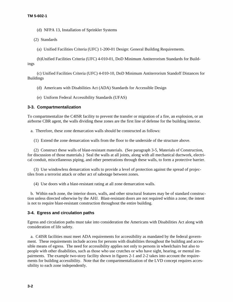
(d) NFPA 13, Installation of Sprinkler Systems (2) Standards (a) Unified Facilities Criteria (UFC) 1-200-01 Design: General Building Requirements. (b)Unified Facilities Criteria (UFC) 4-010-01, DoD Minimum Antiterrorism Standards for Build-ings (c) Unified Facilities Criteria (UFC) 4-010-10, DoD Minimum Antiterrorism Standoff Distances for Buildings (d) Americans with Disabilities Act (ADA) Standards for Accessible Design (e) Uniform Federal Accessibility Standards (UFAS) 3-3. Compartmentalization To compartmentalize the C4ISR facility to prevent the transfer or migration of a fire, an explosion, or an airborne CBR agent, the walls dividing these zones are the first line of defense for the building interior. a. Therefore, these zone demarcation walls should be constructed as follows: (1) Extend the zone demarcation walls from the floor to the underside of the structure above. (2) Construct these walls of blast-resistant materials. (See paragraph 3-5, Materials of Construction, for discussion of those materials.) Seal the walls at all joints, along with all mechanical ductwork, electri-cal conduit, miscellaneous piping, and other penetrations through these walls, to form a protective barrier. (3) Use windowless demarcation walls to provide a level of protection against the spread of projec-tiles from a terrorist attack or other act of sabotage between zones. (4) Use doors with a blast-resistant rating at all zone demarcation walls. b. Within each zone, the interior doors, walls, and other structural features may be of standard construc-tion unless directed otherwise by the AHJ. Blast-resistant doors are not required within a zone; the intent is not to require blast-resistant construction throughout the entire building. 3-4. Egress and circulation paths Egress and circulation paths must take into consideration the Americans with Disabilities Act along with consideration of life safety. a. C4ISR facilities must meet ADA requirements for accessibility as mandated by the federal govern-ment. These requirements include access for persons with disabilities throughout the building and acces-sible means of egress. The need for accessibility applies not only to persons in wheelchairs but also to people with other disabilities, such as those who use crutches or who have sight, hearing, or mental im-pairments. The example two-story facility shown in figures 2-1 and 2-2 takes into account the require-ments for building accessibility. Note that the compartmentalization of the LVD concept requires acces-sibility to each zone independently.
TM 5-602-1
3-3
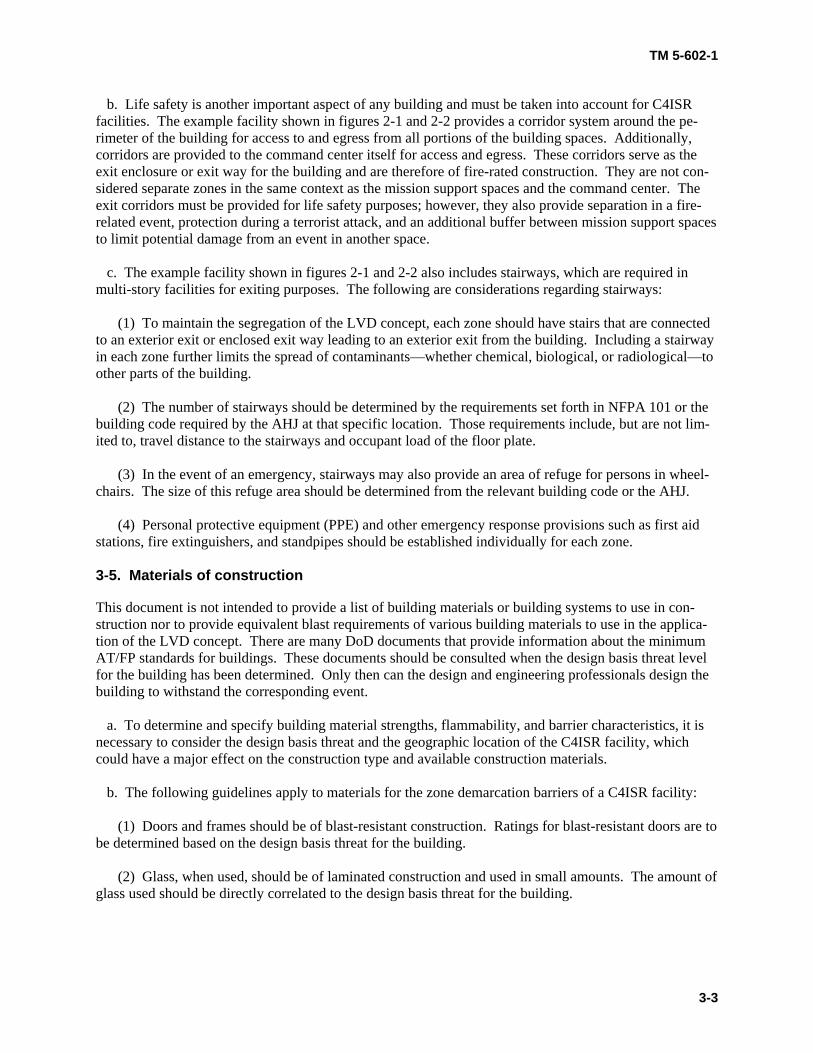
b. Life safety is another important aspect of any building and must be taken into account for C4ISR facilities. The example facility shown in figures 2-1 and 2-2 provides a corridor system around the pe-rimeter of the building for access to and egress from all portions of the building spaces. Additionally, corridors are provided to the command center itself for access and egress. These corridors serve as the exit enclosure or exit way for the building and are therefore of fire-rated construction. They are not con-sidered separate zones in the same context as the mission support spaces and the command center. The exit corridors must be provided for life safety purposes; however, they also provide separation in a fire-related event, protection during a terrorist attack, and an additional buffer between mission support spaces to limit potential damage from an event in another space. c. The example facility shown in figures 2-1 and 2-2 also includes stairways, which are required in multi-story facilities for exiting purposes. The following are considerations regarding stairways: (1) To maintain the segregation of the LVD concept, each zone should have stairs that are connected to an exterior exit or enclosed exit way leading to an exterior exit from the building. Including a stairway in each zone further limits the spread of contaminants—whether chemical, biological, or radiological—to other parts of the building.
(2) The number of stairways should be determined by the requirements set forth in NFPA 101 or the building code required by the AHJ at that specific location. Those requirements include, but are not lim-ited to, travel distance to the stairways and occupant load of the floor plate.
(3) In the event of an emergency, stairways may also provide an area of refuge for persons in wheel-chairs. The size of this refuge area should be determined from the relevant building code or the AHJ.
(4) Personal protective equipment (PPE) and other emergency response provisions such as first aid stations, fire extinguishers, and standpipes should be established individually for each zone. 3-5. Materials of construction This document is not intended to provide a list of building materials or building systems to use in con-struction nor to provide equivalent blast requirements of various building materials to use in the applica-tion of the LVD concept. There are many DoD documents that provide information about the minimum AT/FP standards for buildings. These documents should be consulted when the design basis threat level for the building has been determined. Only then can the design and engineering professionals design the building to withstand the corresponding event. a. To determine and specify building material strengths, flammability, and barrier characteristics, it is necessary to consider the design basis threat and the geographic location of the C4ISR facility, which could have a major effect on the construction type and available construction materials. b. The following guidelines apply to materials for the zone demarcation barriers of a C4ISR facility: (1) Doors and frames should be of blast-resistant construction. Ratings for blast-resistant doors are to be determined based on the design basis threat for the building.
(2) Glass, when used, should be of laminated construction and used in small amounts. The amount of glass used should be directly correlated to the design basis threat for the building.

TM 5-602-1
4-1
CHAPTER 4 MECHANICAL SYSTEMS
4-1. Mechanical design criteria The intent of the LVD concept, described in paragraph 2-3, Limited Vulnerability Design Concept, is to create a facility that is self-sufficient and capable of surviving a single internal threat event. For mechani-cal systems, this requires a design that provides the ability to adapt in response to a detected flood, explo-sion, or CBR event within an area and thereby protects the remaining spaces for the duration of the mis-sion. Paragraph 4-7b(1), Relative Pressurization, discusses these system reactions in detail. The designer should provide means by which service throughout the facility can meet mission RAM criteria. Some recommended methods are system redundancy, multiple utility services, and alternate fuel sources, as discussed in paragraph 4-3, System Reliability. a. The ability to maintain functionality in the remaining spaces in spite of an event in a single zone is critical. Accordingly, the designer should design the mechanical systems serving those spaces in a man-ner that mitigates their inherent vulnerabilities to internal threat events. An added benefit of such design considerations is that many of the measures that reduce the vulnerability of facilities also provide en-hanced protection against natural and accidental incidents. However, the designer should ensure that any measures taken to reduce the vulnerability of the facility to an internal attack do not inhibit normal opera-tion. The measures must also be capable of immediate, seamless implementation and should follow a regular testing and maintenance schedule. b. At a minimum, the designer should consider the following basic criteria to ensure self-sufficiency and reliability of mechanical systems in the design of C4ISR facilities. (1) There should be at least two independent sources for external utilities.
(2) Mechanical systems at a minimum redundancy of N+2 should serve mission-critical zones (such as command centers).
(3) All external critical utilities (such as water or natural gas) should include an internal well, internal storage capacity, or alternate fuel that is sufficient for the established facility mission time. The water source should be sufficient for potable and makeup water uses. 4-2. Applicable codes and standards for mechanical systems The following codes and standards govern the design of mechanical systems as part of the LVD concept: a. TM 5-691, Utility Systems Design Requirements for Command, Control, Communications, Com-puter, Intelligence, Surveillance, and Reconnaissance (C4ISR) Facilities b. TM 5-810-1, Mechanical Design: Heating, Ventilating, and Air Conditioning 4-3. System reliability The overall level of reliability required for the operation of a C4ISR facility is very high. To achieve this, the LVD concept supports the creation of self-supporting peripheral zones serving a central command center. These peripheral zones contain less critical functions, enabling the facility as a whole to accept

TM 5-602-1
4-2
the loss of a single peripheral zone to an internal event as long as service to the surviving zones remains intact. For this purpose, the LVD concept incorporates dedicated mechanical systems and utility connec-tions for each zone. The functions of the command center are the most critical to the facility mission. Consequently, the designer should take extra measures to improve the reliability of systems serving it. In accordance with this requirement, the designer should consider the use of system redundancy and alter-nate fuels, specifically with regard to achieving the minimum required N+2 redundancy for the command center. a. Redundancy is a proven concept used to increase system reliability, in the LVD concept, the periph-eral zones house dedicated mechanical rooms. These rooms contain the main mechanical equipment and hydronic piping mains. They also provide the entry point for all external utilities serving the building. Building operation depends on having adequate backup to all critical systems in the event of a disruption in a single zone. Therefore, redundancy for both external utilities and HVAC systems is required. (1) Under normal operation, C4ISR facility operation typically relies on public utility systems. These utilities include water, sewer, and natural gas. Given the reliability requirements for the facility, however, dependence on a single source for these utilities is not recommended. The designer should coordinate with other disciplines and local utility providers to ensure that the utilities brought to the site have at least two independent sources. (a) Each zone should have dedicated taps off these utility mains, with appropriate contaminant sen-sors, backflow prevention (on water), and shutoff capabilities to protect the main lines. Paragraph 4-5, Automatic Isolation and Backfeed, discusses these devices in more detail. (b) A dedicated sewer line and storm drain system should also support each zone. The sewer lines should not combine into a common line until outside the facility perimeter. Composting toilets or other means should be available in case sewer service is lost due to an event. Any storm drains serving the command center area should route through the peripheral zone systems. Overflow capability is typically required for a storm drain system design per code and should be adequate for system backup. (2) Heating, ventilation, and air-conditioning should also utilize redundancy to increase system reli-ability. In addition to serving the associated zone, each peripheral mechanical system (wet and dry side) should share an equal portion of the command center load to meet the N+2 redundancy criteria. The de-signer should size each zone's mechanical systems so that if an event during maintenance were to result in the loss of two of the supporting peripheral zones, the remaining mechanical systems would be able to handle 100 percent of the command center load (see figure 4-1). If the number of peripheral zones ex-ceeds five, to limit the system cross-connections, the designer should select only five of those zones (spread throughout the building) to serve the command center. Similarly, the computer air-conditioning units (CACs) located within the command center should support the load so that two units can be lost without affecting the command center. b. The requirements for self-sufficiency dictate the provision of internal sources for utilities that are critical to facility operation. Some of these requirements are: (1) In the case of water, each zone may have an internal well or storage tank. In the case of fuel for boilers and generators, liquid fuel (diesel) is likely to be the most practical to store internally, but com-pressed natural gas, propane, or other fuels may be considered. (2) Storage capacity should be based on the defined mission time for each specific facility and may require significant physical space. For example, to provide 3 days of storage for the example facility would require approximately 14,000 gallons of water and approximately 4,600 gallons of diesel fuel for

TM 5-602-1
4-3
each of the four peripheral zones. This may dictate adding a below-grade level to the building dedicated to storage tanks.
CC
Z 1 Z 2
Z 3 Z 4
CC
Z 1 Z2
Z 3 Z 4
Z 5
CC
Z 1
Z 2
Z 3
Z 4
Z 5 Z 6
CC
Z 1 Z 2
Z 3 Z 4
CCCC
Z 1Z 1 Z 2Z 2
Z 3Z 3 Z 4Z 4
CC
Z 1 Z2
Z 3 Z 4
Z 5
CCCC
Z 1Z 1 Z2Z2
Z 3Z 3 Z 4Z 4
Z 5Z 5
CC
Z 1
Z 2
Z 3
Z 4
Z 5 Z 6
CCCC
Z 1Z 1
Z 2Z 2
Z 3Z 3
Z 4Z 4
Z 5Z 5 Z 6Z 6Zone + 25%CC
ZONE CONTRIBUTION WITH ONE ZONE
DOWN
Zone + 25%CC
ZONE CONTRIBUTION WITH ONE ZONE
DOWN
Zone + 33%CC
ZONE CONTRIBUTION WITH ONE ZONE
DOWN
FOUR PERIPHERAL ZONES
NORMAL CONTRIBUTION TO COMMAND CENTER
(CC)
ZONE CAPACITY (Contribution
Equivalent to 2 Zones Down)
20%Zone + 33% CC
NORMAL CONTRIBUTION TO COMMAND CENTER
(CC)
ZONE CAPACITY (Contribution
Equivalent to 2 Zones Down)
20%Zone + 33% CC
FIVE PERIPHERAL ZONES
SIX PERIPHERAL ZONES
25%Zone + 50% CC
NORMAL CONTRIBUTION TO COMMAND CENTER
(CC)
ZONE CAPACITY (Contribution
Equivalent to 2 Zones down)
Zone + 25%CC
ZONE CONTRIBUTION WITH ONE ZONE
DOWN
Zone + 25%CC
ZONE CONTRIBUTION WITH ONE ZONE
DOWN
Zone + 33%CC
ZONE CONTRIBUTION WITH ONE ZONE
DOWN
FOUR PERIPHERAL ZONES
NORMAL CONTRIBUTION TO COMMAND CENTER
(CC)
ZONE CAPACITY (Contribution
Equivalent to 2 Zones Down)
20%Zone + 33% CC
NORMAL CONTRIBUTION TO COMMAND CENTER
(CC)
ZONE CAPACITY (Contribution
Equivalent to 2 Zones Down)
20%Zone + 33% CC
FIVE PERIPHERAL ZONES
SIX PERIPHERAL ZONES
25%Zone + 50% CC
NORMAL CONTRIBUTION TO COMMAND CENTER
(CC)
ZONE CAPACITY (Contribution
Equivalent to 2 Zones down)
Figure 4-1. Scaled peripheral zone support of the command center 4-4. Plumbing distribution system configuration Each peripheral zone requires access to systems served by external utilities. One approach the designer may use involves pressurized loops around the building. Figure 4-2 illustrates this approach, showing the main lines for two external utilities (water and gas) routed in loops around the example facility, inside the secure perimeter. Two independent external sources (labeled W1, W2, G1, and G2 in the figure) serve each loop as discussed in paragraph 4-3a(1), External Utilities. These sources are provided with check valves to prevent backflow. The loops are also equipped with shutoff valves to isolate a portion of the loop should it be damaged. To meet the self-sufficiency criteria, a third source of water (labeled W3 in the figure) is required for each zone. This may be a well or a storage tank but, in either case, should be located within or beneath the zone. These sources should be of sufficient size to provide makeup water to the zone cooling tower (if the required storage tank size is prohibitively large, air-cooled heat rejection should be considered). a. The designer may choose to provide storage capacity for natural gas as well, but the alternate liquid fuel option may be more feasible. In either case, fuel storage capacity should be provided in each zone. Taps off the main line provide dedicated service to each zone. These taps should have hydro-pneumatic tanks on the lines to replace losses due to leakage. The command center receives domestic water service from taps off the dedicated zone water lines. Design of the domestic hot water system is at the discretion of the designer and is not critical for mission operation.

4-4
TM 5-602-1
Figure 4-2. Zoned utility connections
TM 5-602-1
4-5
b. Locating utility loops inside the secure perimeter should protect the local water and gas mains from potential threats; however, the designer should also consider protecting the building from sewer system tampering. The sewer lines and storm drains for each zone should preferably route to the exterior of the building rather than passing beneath another zone. Potential vulnerabilities in a sewer system include those of explosion and system backflow. In addition to zoning the vent and waste lines, the designer could address these vulnerabilities by including a couple of extra design precautions. Recommended pre-cautions involve oversizing the system vents to reduce the effects of explosion and terminating the vents with goosenecks at the roof level to deter the introduction of foreign substances. Another precaution is to include backwater valves in the sewer lines to prevent CBR contamination of the building through sewer system backflow. Secured cleanouts for water and waste lines should be located inside the building. Vent lines internal to the building and exiting to the building roof are not defensible through mechanical means; protection of these is dependent on limitation of access to the roof. 4-5. Plumbing system – automatic isolation and backfeed The designer can mitigate the vulnerability of plumbing systems to CBR contamination by employing the redundancy of sources and system segregation techniques discussed previously. The designer should also take additional measures by providing backflow protection, detection, and isolation devices, as follows: a. Equip zone water lines with a control valve for isolation, coupled with contaminant detection up-stream of the valve. Electrically actuated isolation valves, controlled from a central system, automatically close upon detection of a contaminant within the main utility stream. This measure prevents contami-nants introduced at the utility level from contaminating everything downstream. b. Provide additional shutoff and detection devices on the water lines between the peripheral zone and the command center to protect the water from zone-level contamination. c. Include shutoff valves in the main loop to permit isolation and partial operation of the loop in the event that one side is damaged. These devices should close upon loss of pressure on one side of the loop.
d. Where appropriate, equip utilities with backflow prevention devices. These devices prevent con-tamination at the zone level from leeching back into the main supply line and rendering it unusable for other zones. Also provide backflow prevention (such as check valves) in the utility source lines to pre-vent loss of flow from the loop if pressure is lost in a source line. 4-6. Fire protection water and suppression systems Fire protection water follows the same configuration as domestic water: it is looped beneath the building, with each zone tapped separately from the main line through the appropriate shutoff and backflow pre-vention. Due to the large volume required, fire protection water typically does not have an internal water tank as backup. a. This is acceptable because the command center, housing the most critical facility functions, is pro-vided with a clean-agent fire suppression system in lieu of a fire sprinkler system. External water tanks or surface water sources may be considered for backup of the regular fire protection system under special circumstances such as remotely located facilities. b. The command center fire suppression system is a clean-agent delivery system designed to safeguard both the equipment and occupants within the command center. To minimize the impact on command center operations, the suppression system should be controlled in two stages. This facility is assumed to be staffed on a continuous basis; therefore, the first line of defense in the event of a fire should allow the

TM 5-602-1
4-6
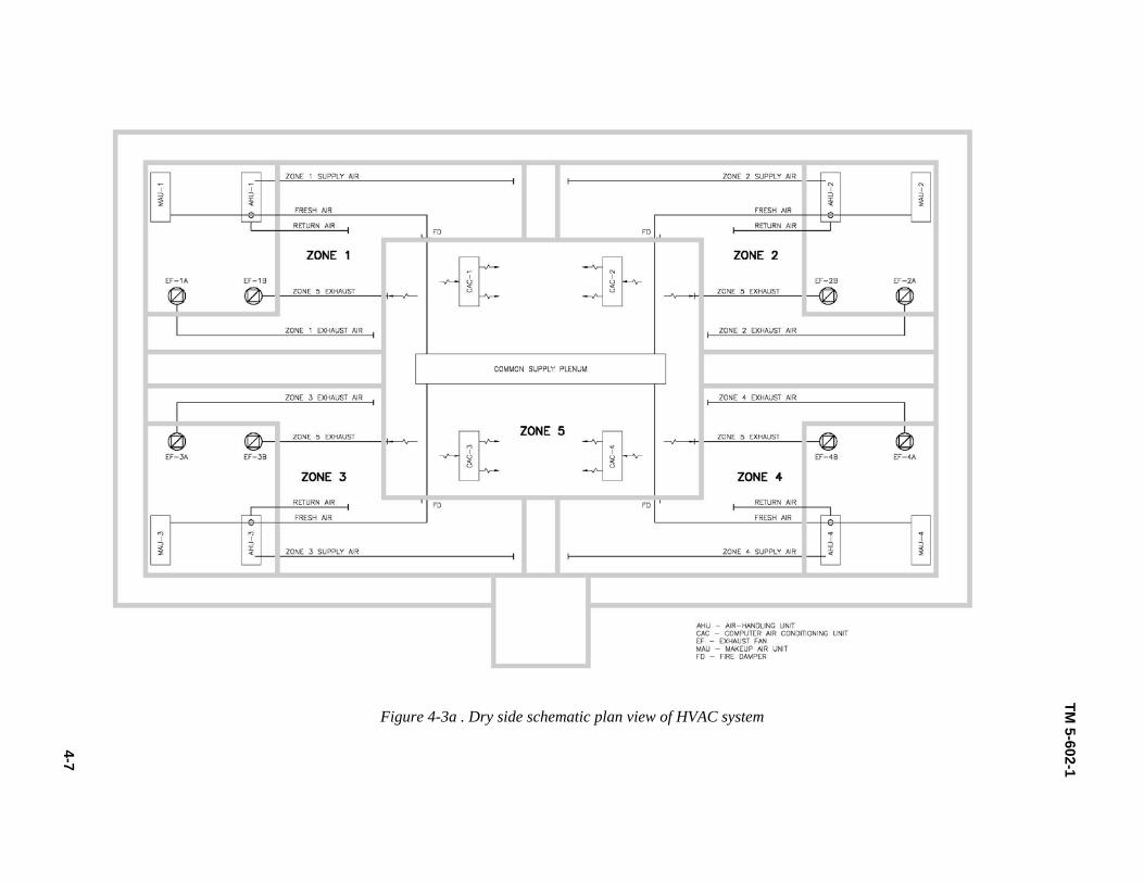
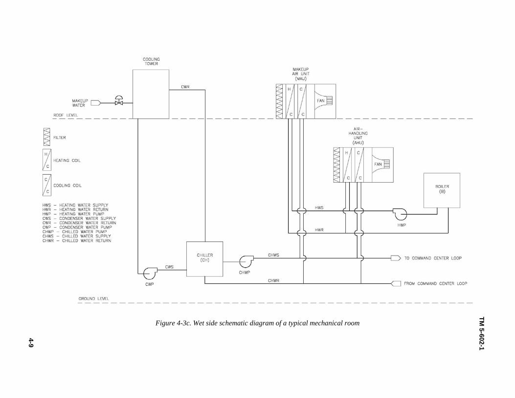
staff the opportunity to address the fire with hand-held equipment. Thus, the first control stage for the system should be to alarm only. The second stage should activate the automatic clean-agent fire suppres-sion system to extinguish the fire. The location of the clean-agent tanks and controls for this system should be within the command center secure zone. 4-7. Heating, ventilation, and air-conditioning systems In addition to providing general space conditioning and occupant comfort, the goal of an HVAC system design generally is "…to achieve isolation of contaminated spaces and provision of safe egress paths or safe refuges for building occupants" (American Society of Heating, Refrigerating and Air-Conditioning Engineers [ASHRAE] Journal, September 2004). C4ISR facilities are unique in that the continuance of the mission is more critical than the survival of building occupants in a zone affected by an event. Never-theless, the LVD concept endeavors to safeguard personnel to the degree possible while still supporting the mission. The intent is to accomplish this purpose using available proven technologies or strategies, not specialized systems. Some potential strategies are pressurization, filtration, and isolation of systems. a. Figures 4-3a and 4-3b illustrate the relationship of the zone HVAC systems to their associated zone and to the command center. Figure 4-3c conveys a more detailed schematic of the wet side at the me-chanical room. All peripheral zones have similar configurations, as shown in figures 4-3a, b, and c. In this example, each of the four zones can support the zone load plus 50 percent of the command center load as discussed in paragraph 4-3a(2), Heating, Ventilation, and Air-Conditioning. b. The rooftop makeup air-handling units (MAUs) provide filtered fresh air for the zone air-handling units (AHUs) and the command center. The AHU mixes the space return air with the fresh air to supply air to the zone. A gas-fired boiler (B) provides heating water that warms the air stream while a water-cooled chiller (CH), paired with a roof-mounted cooling tower (CT) and condenser water pump (CWP), provides the means for cooling. CACs provide cooling for the command center, rejecting heat to the chilled water system. Heating water and chilled water pumps (HWP and CHWP) circulate the water to serve the zone-level MAU, AHU, and terminal unit coils. They also feed a pressurized loop within the command center serving the CACs. Roof-mounted exhaust fans (EF) pull exhaust air from the spaces. (1) Building pressurization may have little effect during a flood or explosion, but it can provide a level of containment and protection in a fire or CBR release event. To compensate effectively for a CBR event, the building pressurization system should have the ability to be dynamic. The HVAC design should positively pressurize the entire C4ISR facility relative to the outdoors. The "level of pressuriza-tion should be based on the pressures that need to be overcome, primarily those due to wind and stack effects, but also those induced by system operation. Therefore, each building's pressurization strategy should be designed based on the climate, the building height and the envelope leakage" (ASHRAE Jour-nal, September 2004). A pressure gradient should also exist between zones, resulting in airflow from critical areas to support zones and then to the building exterior. Upon detection of a contaminant, a spe-cial controls routine should initiate the shutdown of all supply to and exhaust from the contaminated space. Surrounding zones should increase pressurization with respect to the affected area by adjusting their fan speed to prevent cross-contamination. These adjustments in the mechanical systems should keep the contaminant contained within the zone of origin.
TM 5-602-1
4-7
Figure 4-3a . Dry side schematic plan view of HVAC system

4-8
TM 5-602-1
Figure 4-3b. Wet side schematic plan view of HVAC system
TM 5-602-1
4-9
Figure 4-3c. Wet side schematic diagram of a typical mechanical room
TM 5-602-1
4-10
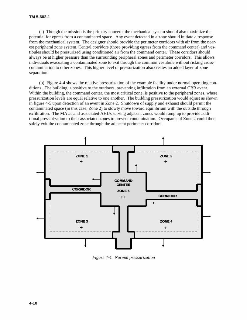
(a) Though the mission is the primary concern, the mechanical system should also maximize the potential for egress from a contaminated space. Any event detected in a zone should initiate a response from the mechanical system. The designer should provide the perimeter corridors with air from the near-est peripheral zone system. Central corridors (those providing egress from the command center) and ves-tibules should be pressurized using conditioned air from the command center. These corridors should always be at higher pressure than the surrounding peripheral zones and perimeter corridors. This allows individuals evacuating a contaminated zone to exit through the common vestibule without risking cross-contamination to other zones. This higher level of pressurization also creates an added layer of zone separation. (b) Figure 4-4 shows the relative pressurization of the example facility under normal operating con-ditions. The building is positive to the outdoors, preventing infiltration from an external CBR event. Within the building, the command center, the most critical zone, is positive to the peripheral zones, where pressurization levels are equal relative to one another. The building pressurization would adjust as shown in figure 4-5 upon detection of an event in Zone 2. Shutdown of supply and exhaust should permit the contaminated space (in this case, Zone 2) to slowly move toward equilibrium with the outside through exfiltration. The MAUs and associated AHUs serving adjacent zones would ramp up to provide addi-tional pressurization to their associated zones to prevent contamination. Occupants of Zone 2 could then safely exit the contaminated zone through the adjacent perimeter corridors.
ZONE 1 ZONE 2
ZONE 4ZONE 3
COMMAND CENTER
ZONE 5
++
+
CORRIDOR
CORRIDOR
+ +
+
ZONE 1 ZONE 2
ZONE 4ZONE 3
COMMAND CENTER
ZONE 5
++
+
CORRIDOR
CORRIDOR
ZONE 1 ZONE 2
ZONE 4ZONE 3
COMMAND CENTER
ZONE 5
++
+
CORRIDOR
CORRIDOR
ZONE 1 ZONE 2
ZONE 4ZONE 3
COMMAND CENTER
ZONE 5
++
+
CORRIDOR
CORRIDOR
ZONE 1 ZONE 2
ZONE 4ZONE 3
COMMAND CENTER
ZONE 5
++
+
CORRIDOR
CORRIDOR
ZONE 1 ZONE 2
ZONE 4ZONE 3
COMMAND CENTER
ZONE 5
++
+
CORRIDOR
CORRIDOR
+ +
+
Figure 4-4. Normal pressurization

TM 5-602-1
4-11
++ 0
++
ZONE 1 ZONE 2
ZONE 4ZONE 3
COMMAND CENTER
ZONE 5
+++
++
CORRIDOR
CORRIDOR
++
++
++ 0
++
ZONE 1 ZONE 2
ZONE 4ZONE 3
COMMAND CENTER
ZONE 5
+++
++
CORRIDOR
CORRIDOR
ZONE 1 ZONE 2
ZONE 4ZONE 3
COMMAND CENTER
ZONE 5
+++
++
CORRIDOR
CORRIDOR
ZONE 1 ZONE 2
ZONE 4ZONE 3
COMMAND CENTER
ZONE 5
+++
++
CORRIDOR
CORRIDOR
ZONE 1 ZONE 2
ZONE 4ZONE 3
COMMAND CENTER
ZONE 5
+++
++
CORRIDOR
CORRIDOR
++
++
Figure 4-5. Emergency pressurization
(2) The design of mechanical systems for the LVD concept should rely on standard equipment and a segregation strategy rather than specialized systems. With this strategy, the loss of some peripheral zones is acceptable as long as the command center remains operable. Thus, the AHUs serving the zones need only to follow standard commercial design practice for filtration. However, the design of the MAUs should include filtration in accordance with standard guidelines for CBR protection. Use of CBR filtra-tion on the MAUs not only provides an additional level of protection for building occupants, but also ex-pedites cleanup efforts of a contaminated zone. PPE such as gas masks, suits, and gloves should also be available to occupants in the case of a CBR event. The designer may also choose to supplement the filters with ultraviolet light (type C) emitters located within the MAUs to act as a germicide. (3) Chilled and heating water systems serve the MAU, AHU, CAC, and terminal unit coils in a facil-ity. Provided that they undergo proper maintenance, these systems are less vulnerable to a CBR attack than other systems. However, chilled water is an especially critical system due to the cooling require-ments for equipment in the command center. An explosion or similar event is more likely to affect this particular system. Hydronic systems should have quick shutoff devices on the supply and return side of the water loops to prevent loss of water from the command center loop in the event a zone is lost. The supply side should also have a check valve. (a) These devices should be located within the command center zone. Once these devices shut off a zone, the unaffected zones will continue to support the command center loop. Hydro-pneumatic tanks should be provided in the chilled water lines (just prior to the shutoff valves) in other zones to replace chilled water leak loads. TM-5-691 contains additional discussion of hydronic system vulnerabilities and equipment configuration. (b) The size and quantity of CACs required to cool the command center depends on the types and amount of electronic equipment, the number of occupants, and the arrangement of the space. For illustra-

TM 5-602-1
4-12
tion purposes, four units are shown serving the command center, but the actual number should be deter-mined from load calculations and the N+2 redundancy requirement. (4) Isolation and control devices used in the control of mechanical systems also should be readily available technologies, not specialized systems. For instance, the controls developed to modulate air-handling systems for building pressurization in a CBR event should be similar to the industry standard strategies and devices for smoke control. Automatic, quick-shutoff, piston- or electrically actuated sole-noid control valves for utilities are available in sizes as large as 2 inches in diameter. For larger water pipes up to 8 inches in diameter, electrically actuated, spring-return butterfly valves are available. These devices should operate in less than 10 seconds with fail-safe positioning, typically fail closed. Actuators on time-critical dampers (which must open or close quickly, such as emergency generator exhaust damp-ers) should be a spring-return type with a safety function.

TM 5-602-1
5-1
CHAPTER 5 ELECTRICAL SYSTEMS
5-1. Electrical design criteria The design of electrical service and distribution systems should be consistent with industry standards such as those produced by the Institute of Electrical and Electronics Engineers (IEEE), NFPA, and the Ameri-can National Standards Institute (ANSI) as well as applicable DoD guidelines and standards. System de-signs should make use of utility-grade equipment and components to support reliability and maintainabil-ity. While there is no formal standard definition, utility grade is generally distinguished from commercial grade by construction and features that support extended life expectancy, tolerance of adverse environ-ments, and ease of access and disassembly for testing and maintenance. Examples of the difference are shown in table 5-1.
Table 5-1. Features of utility-grade and commercial-grade equipment
Utility Grade Commercial Grade Drawout-mounted protective devices with tested surge withstand capability for power system re-laying
Surface-mounted relays with no tested withstand ratings
Switchgear complying with Underwriters Labora-tories Inc. (UL) Standard 1558 construction stan-dards
Switchboards complying with UL Standard 891 construction standards
Low-voltage power circuit breakers rated to ANSI Standard C37 and UL Standard 1066
Molded-case or insulated-case circuit breakers rated to UL Standard 489
5-2. Applicable electrical codes and standards The following specific standards are of particular concern in the design of electrical systems to support the LVD concept: a. TM 5-689, ADP/Computer Electrical Installation and Inspection for Command, Control, Communi-cations, Computer, Intelligence, Surveillance, and Reconnaissance (C4ISR) Facilities. b. TM 5-690, Grounding and Bonding in Command, Control, Communications, Computer, Intelli-gence, Surveillance, and Reconnaissance (C4ISR) Facilities. c. TM 5-693, Uninterruptible Power Supply Selection, Installation, and Maintenance for Command, Control, Communications, Computer, Intelligence, Surveillance, and Reconnaissance (C4ISR) Facilities d. NFPA 70, National Electrical Code (NEC). e. NFPA 70B, Recommended Practice for Electrical Equipment Maintenance. f. IEEE Standard 242, Recommended Practice for Protection and Coordination of Industrial and Com-mercial Power Systems.

TM 5-602-1
5-2
g. IEEE Standard 493, Recommended Practice for Design of Reliable Industrial and Commercial Power Systems. h. IEEE Standard 1100, Recommended Practice for Powering and Grounding Sensitive Electronic Equipment. i. ANSI C37, Standards Collection: Circuit Breakers, Switchgear, Substations, and Fuses. 5-3. Segregation and separation Segregation and separation of power generation, power distribution, equipment and controls is necessary to provide the ability of the system to reliably and safely function in the event of a catastrophic event. a. Figure 5-1 shows one possible arrangement of utility service, standby generation, and power distri-bution for the example facility. In this case, each peripheral zone bus has local standby generation ade-quate to carry the contingency load on that bus. The load on each bus consists of the demand load of that zone of the building plus a share of the command center demand load. Loss of a single peripheral zone results in a loss of only one of the four feeders to the command center. These feeders should be routed entirely within the zone of origin until they cross the barrier wall into the command center. (1) Within the command center, it is assumed that physical segregation of utility supplies to protect from explosive threat is not necessary. However, it remains critical to provide adequate segregation in-ternal to equipment to prevent an arcing fault from propagating to affect multiple sources. (2) Figure 5-1 shows a possible arrangement of transfer equipment when the command center loads are served from a 2N uninterruptible power supply (UPS) and mechanical system. The normally open tie circuits isolate the "A" buses from the "B" buses so that no single component failure can affect both sides. b. Segregation of controls is also critical. A significant advantage of the distribution scheme shown in figure 5-1 is that independent transfer controls can be provided for the redundant portions of the system. Each service has an automatic bus transfer scheme that starts the generator and transfers the bus on failure of the utility source; there is no need for common controls between services. Similarly, within the com-mand center, the "A" and "B" distribution is provided with separate automatic transfer controls. Redun-dancy of the electrical system should be selected to match the redundancy of the mechanical and other loads it serves. It may be tempting to increase the degree of redundancy by providing tie circuits between the services or by automating the tie breakers between the "A" and "B" buses within the command center. This would result in higher calculated availability due to more combinations of paths to the load but would require that control systems cross the segregation boundaries established for the distribution. This risks actually lowering availability by complicating the control scheme and introducing the potential for a control system failure to produce common-mode failure of multiple distribution paths. 5-4. Protective device coordination Electrical systems in all areas of the C4ISR facility should be designed for selective coordination of over-current and other modes of protection according to IEEE Standard 242. It is particularly critical that the distribution system within the command center zone be selective to prevent a single internal fault from propagating upstream to the feeders that supply this zone from the peripheral zones. Electrical system reliability calculations verifying compliance with mission requirements generally assume that protective devices are selectively coordinated; failure to design for complete selectivity will result in the actual reli-ability of the command center service being significantly lower than the calculated values.

TM 5-602-1
5-3
Figure 5-1. Example facility single-line diagram
TM 5-602-1
5-4
a. It is assumed that power distribution within the facility will be at 480V or higher due to the large mechanical loads. Such systems, where ground fault protection (GFP) is required, should be designed as 3-phase, 3-wire systems without line-to-neutral loads. This simplifies the GFP schemes and reduces the probability of nuisance tripping. If line-to-neutral loads, such as 277V lighting, must be served, dedicated distribution for them should be provided by separate isolation transformers. This is a particularly valu-able design approach for systems such as this, having load transfer downstream of the feeder circuit breakers; if the distribution were a 4-wire system, the large number of neutral tie points would lead to ex-tremely complicated GFP schemes. b. Within each peripheral zone, feeder circuit breakers must be selectively coordinated with the utility and generator source circuit breakers. This prevents a fault on a feeder within the zone from interrupting service from that zone to the command center. Generator current decrement characteristics must be con-sidered to maintain the selectivity attained for operation from the utility when operating from the higher source impedance of the generator. The number of levels of GFP should correspond to the number of levels of phase overcurrent protection. c. For the command center service configuration shown, feeder circuit breakers from the main buses to the mechanical and UPS loads must be selectively coordinated with the main circuit breakers on each in-coming service. If possible, each main circuit breaker within the command center should also be coordi-nated with the circuit breaker on the other end of that circuit in the peripheral zone. This prevents a feeder breaker failure within the command center from causing a trip of the supply circuit, which could be misread by the supervisory control and data acquisition (SCADA) controls as an outage and could lead to automatic transfer of the faulted bus to the other supply circuit. 5-5. Grounding and surge protection Grounding and surge voltage protection of power circuits within the facility is critical to preventing elec-trical transients, generated naturally or as a threat, from presenting a common-mode failure opportunity for the electrical systems. a. Control system circuits crossing zone boundaries should use fiber optic cable to eliminate this possi-bility entirely. Surge protection should be installed in compliance with IEEE Standard 1100, with par-ticular attention to effective grounding. b. The facility should have a common ground system, designed and constructed in compliance with TM 5-690. It is neither practical nor technically sound to attempt to establish separate ground systems by zone. Rather, attention should be paid to effective bonding and to creating a low-impedance ground grid to minimize potential differences between zones across the full spectrum of surge and noise frequencies. If a single-point grounding system is used, the main ground bar should be located within the command center zone. 5-6. Physical installation Conduits passing between the peripheral zones and the command center zone should be routed underneath the floor slab whenever possible. This decreases the number of penetrations required in the zone barrier walls, which may reduce their structural strength as well as create vulnerable points for a blast threat. Placing these conduits under the slab improves their survivability in the event that an explosion or fire event damages the interior of the zone but leaves the mechanical and electrical utility space intact. Con-duits and other raceways crossing zone boundaries, regardless of routing, should be sealed to prevent the transmission of liquids or gases between zones via the conduit path. Where penetration of zone barrier walls is required, the structural engineer should be consulted for construction details to ensure that the

TM 5-602-1
5-5
conduit penetration cannot permit a blast wave to propagate across the boundary. Flanged, cast-in-place conduit sleeves with threaded fittings are recommended as a minimum measure to effectively seal be-tween the wall and the outside of the conduit. 5-7. Standby generation The capacity of standby generation for each peripheral zone should be determined as discussed in Chapter 2, Fundamentals of Limited Vulnerability Design, for the load of that zone plus the share of command center load allocated to that source under contingency conditions. Due to the constant nature of the elec-trical and mechanical loads in the command center, and the possibility of extended operation on standby power, engine and generator ratings should be specified on a continuous basis rather than a prime or standby basis. a. To meet the design criteria of facility operation independent of external utilities, prime movers with fuel storage inside the secured perimeter are required. If the quantity of fuel required for the specified mission time permits, diesel engine generator sets with integral sub-base fuel tanks are a means of both meeting the internal storage requirement and providing redundancy in the fuel supply equivalent to that provided in the generators. If the mission time dictates large quantities of liquid fuel storage, fuel treat-ment to counter the effects of aging may become necessary. Other prime mover technologies and fuel types may also be considered if proven in standby service. b. A consideration with respect to the routing of fuel fill and vent lines from internal storage tanks is their potential exposure to fire and explosion as well as the possibility of introducing contaminants through the lines to the tank. Fuel fill lines for tanks serving separate zones should not be grouped at a common fill station. For reliability, gravity flow is recommended from bulk tanks to engines or day tanks. c. Air supplies used for cooling and combustion air must be protected from unauthorized access and segregated to prevent common-mode threats. The use of rooftop-mounted remote radiators greatly re-duces the amount of air that must be circulated through the space housing the engine-generator, which assists with the design of blast-resistant air intakes. d. In the example facility, it is assumed that a single standby generator is located in each peripheral zone, with a remote radiator mounted on the roof above the mechanical and electrical equipment room. This places the radiator inside the perimeter corridor, where it is relatively well protected from external threats. Air intakes for generator room cooling and combustion air and exhaust of the cooling air must also be within this rooftop area due to the presence of the perimeter corridor. These requirements must be carefully coordinated with those of the mechanical equipment to establish air flow patterns that provide adequate cooling and prevent recirculation of exhaust air into intakes. The use of heat exchangers and either well water or chilled water for engine and engine room cooling can further reduce the air intake size, albeit at the expense of increased chiller and cooling tower size.
TM 5-602-1
6-1
CHAPTER 6 CONTROL SYSTEMS
6-1. Controls system design criteria C4ISR facility systems require the highest possible level of reliability. This is also true of the SCADA systems used to monitor and control the mechanical and electrical systems. In general, the control system layout should mirror the design of the utility systems: if there is an N+2 equipment layout, there should be at least an N+2 control hardware architecture (see paragraph 2-7, Reliability Criteria). All systems should meet the following basic design criteria: a. The expected lifetime of the hardware and software for the control system should be greater than 15 years. b. The control system architecture should be designed to achieve maximum reliability.
c. No single failure should be able to disable the command center or multiple peripheral zones.
d. An N+2 design should be implemented to meet the RAM design criteria. In this design, one area can be out of service for known reasons (such as maintenance) and another area can be out of service for un-planned reasons (such as equipment failure or a terrorist event). e. The costs of cable installation should be taken into account. In other words, communication cables should be used instead of long-distance runs of multiple conductors whenever possible. f. Peripheral zone systems and equipment should be controllable remotely from the command center and locally at the zone. g. The control system hardware should be more reliable than the equipment being controlled, such as pumps and motors (high mean time to fail [MTTF]). h. A single control system failure should affect only one piece of equipment for a limited time duration (low mean time to repair [MTTR]). i. The use of proprietary hardware, software, and communications should be avoided. j. Control equipment should be scaled properly, that is, using small systems for small input/output (I/O) counts and large systems for large I/O counts. 6-2. Applicable control systems codes and standards The following specific standards apply to the design of control systems to support the LVD concept: a. ANSI/[Instrumentation, Systems, and Automation Society] ISA 84.01, Application of Safety Instru-mented Systems for the Process Industries. b. TM 5-601, Supervisory Control and Data Acquisition Systems for Command, Control, Communica-tions, Computer, Intelligence, Surveillance, and Reconnaissance (C4ISR) Facilities
TM 5-602-1
6-2
6-3. Agent detection The detection of CBR agents is a fast-developing area of technology. Many government agencies are working on these technologies. Two of the best sources of the latest information are the Technical Sup-port Working Group (TSWG) and the Centers for Disease Control and Prevention (CDC). Their respec-tive websites are www.tswg.gov and www.cdc.gov. No single device or instrument is expected to be ca-pable of detecting all three types of agents. At least three independent agent detection systems are ex-pected to be required as inputs to the facility SCADA system. A promising area of research involves the use of nanotechnology to develop instruments to detect not only the release of a CBR agent but also the specific agent. This is part of a technology group called Micro-Electrical/Mechanical Systems (MEMS) and Micro-Optical Electrical/Mechanical Systems (MOEMS). a. Some of the most common forms of instrumentation to detect chemical agents are as follows (ac-cording to Griffin Davis, MD, MPH, and Gabor Kelen, MD, [Chemical, Biological, Radiological, Nu-clear and Explosives] CBRNE – Chemical Detection Equipment): (1) Ion Mobility Spectrometer (IMS) – Ion mobility detection is based on the transit speed of chemi-cal agents. This technology is available in handheld devices, fixed site detectors, and remote agent detec-tors. IMS is the basis of most chemical agent detectors made today. It can detect agents such as nerve gas, mustard gas, and vesicants (chemicals that cause skin blisters). The military already uses a stand-alone detector called the M8A1, made by Environmental Technologies Group (ETG). A commercial ver-sion of this device is also available that can transmit information remotely, as is required for a C4ISR fa-cility that incorporates the LVD concept. (2) Infrared Spectrometer (IRS) – Infrared technology looks at the different wavelengths detected in the chemical agent and compares them to the known spectral analysis of each agent. The military uses an M21 Remote Sensing Chemical Agent Alarm (RSCAAL) in the field. (3) Miniature Automatic Continuous Agent Monitoring System (MINICAMS) – This technology uses gas chromatography with flame photometry and enables more specific detection but takes about 3 to 5 minutes to complete each detection cycle. (4) Surface Acoustic Wave (SAW) – This technology uses chemically selective coated crystals that change frequency when detecting a chemical agent. This change can be detected by a microcomputer, thus making the device relatively inexpensive. It is commonly used by civilian response units. b. Some of the most common forms of instrumentation to detect biological agents are as follows (ac-cording to [National Institute of Justice] NIJ Guide 101–00): (1) Wet detection (flow cytometry) instruments – This technology measures cells and particles in a moving fluid as they pass through a testing point. The biological agent can be identified by using laser light scattering, electronics, and computers. Such instruments are made by the Los Alamos National Laboratory and the Becton Dickenson Company. (2) Bacterial spore detection instruments – This technology is made by the Universal Detection Technology Company and acts as an "anthrax smoke detector." It detects the chemical dipicolinic acid, which is inside any bacterial spore. It is suitable for continuous sampling, with detection occurring within 15 minutes of the attack.

TM 5-602-1
6-3
(3) Dry detection (mass spectrometry) instruments – This technology uses mass spectrometry to ob-tain characteristic information on the structure and molecular weight of the sample. The following are the dry detection instruments of this type: (a) Chemical Biological Mass Spectrometer (CBMS) (b) Pyrolysis-Gas Chromatography-Ion Mobility Spectrometer (PY-GC-IMS) (c) Matrix-Assisted Laser Desorption Ionization-Time of Flight-Mass Spectrometry (MALDI-TOF-MS) c. For radiological agent detection, both military and commercial detectors are available. Another con-sideration is the presence of "dirty bombs," which have a different radiological signature than most sources. There are some companies that make detectors for this type of attack. 6-4. Distributed architecture TM 5-601 discusses a variety of possible control system architectures. All C4ISR facilities should have a distributed architecture, which inherently protects against internal control system failures and their conse-quences. The protection of individual control components from any external threat is not economically feasible. Therefore, the principal means of protection is the control cabinet itself and its environmental protection rating. 6-5. Reliability Figure 6-1 shows a control equipment plan for the example C4ISR facility to which the LVD principles have been applied. a. Zones 1 through 4 each contain not only the zone's mechanical and electrical equipment but also the associated control equipment. Each zone contains a control panel for the mechanical equipment and a panel for the electrical equipment. Typically, these panels are supplied with the equipment. In the exam-ple facility, the programmable logic control (PLC) in the electrical panel is replaced by a remote I/O communications module communicating to the PLC in the mechanical panel. Both the mechanical and electrical "programs" reside in the same PLC processor. In addition, the mechanical panel has an operator interface terminal (OIT), housed in the front of the panel, as the means by which an operator can control and monitor the equipment in that zone. With the facility intercommunication system, an operator can also monitor Zones 1 through 4 but not Zone 5, the command center. b. All peripheral zone PLCs are connected to Ethernet switches by fiber optic communications cables. The Ethernet switches are all housed within Zone 5 and connected in a "self-healing" ring topology, as shown in figure 6-2. The fiber optic cables should be the loose-tube type to avoid damage by shock. In addition, Zone 5 contains the following: (1) A redundant PLC system (2) A redundant remote I/O system (3) Six interconnected Ethernet switches (4) A human-machine interface (HMI) system for monitoring and controlling all zones in the facility
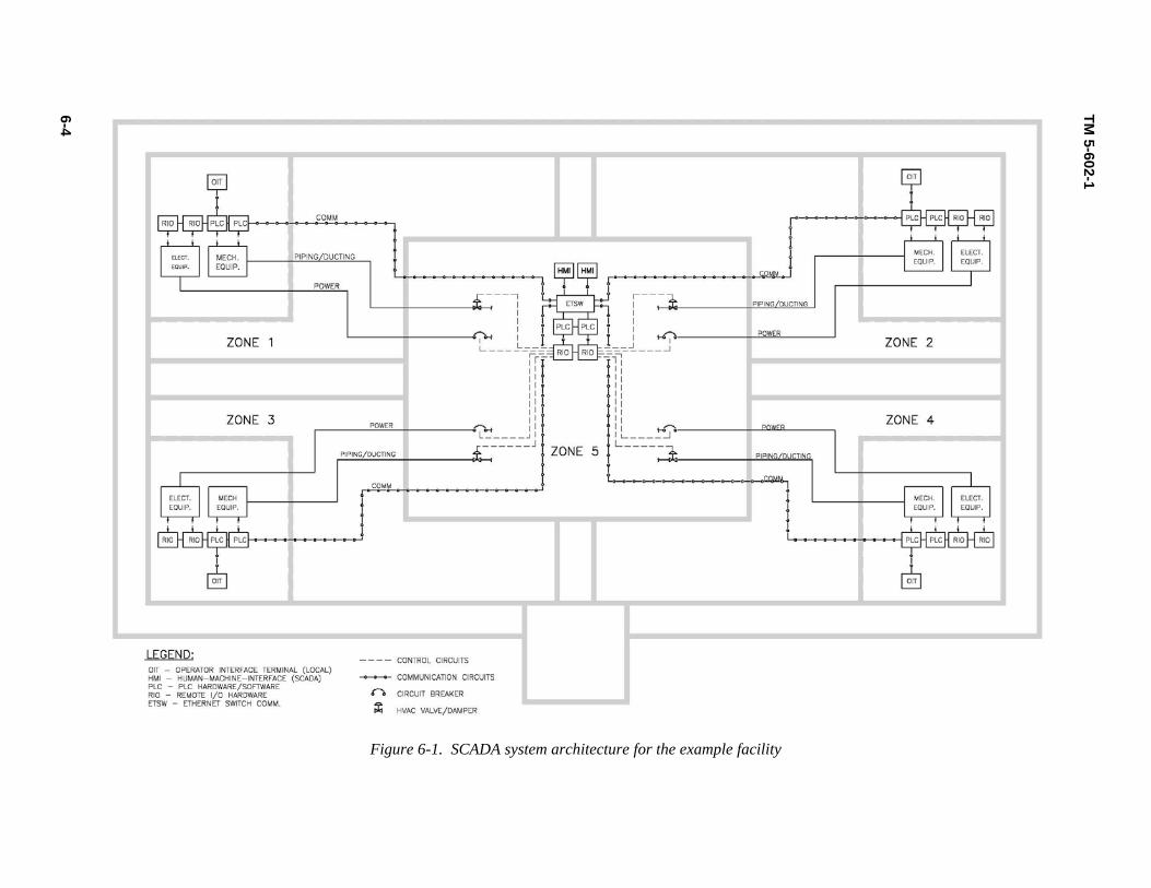
6-4
TM 5-602-1
Figure 6-1. SCADA system architecture for the example facility

TM 5-602-1
6-5
Figure 6-2. Ethernet switches in self-healing ring topology
(5) Each zone’s mechanical and electrical isolation equipment (which is controlled by the Zone 5 PLC) (6) A security computer connected to the communications network c. The security computer contains specialized, commercially available software that monitors the health of all devices on the network. It also controls access to each PLC, HMI, or OIT to ensure the complete integrity of the control system and not allow unauthorized access to the application or system software. For more information on the security computer and its software, see TM 5-601. d. There are two possible ways to implement the required redundancy in Zone 5. Figure 6-1 shows the use of PLC equipment with redundant processors and I/O hardware. In this configuration, I/O signals are wired to two different remote I/O racks, which communicate to two PLC processors in separate chassis with their own power supplies and backup communication modules. In this configuration, one PLC is the primary and the other PLC is designated the secondary. These PLCs use the backup communication modules to determine what the status of the PLCs is and which PLC controls the I/O subsystem and communications.

TM 5-602-1
6-6
(1) Another option is to use commercially available PLC equipment in which the redundancy is built into the PLC hardware through the use of "two out of three" voting logic. This configuration is a single-chassis PLC system that has redundant power supplies and two or three processors. (2) The processors communicate to each other through the chassis backplane and execute "two out of three" voting logic to all input and output modules. The system is programmed as if there were only one processor. 6-6. Survivability With the control equipment plan described in paragraph 6-5, Reliability, the way in which this system would operate can be analyzed. a. Each zone would have its own detection equipment for CBR agents. The expectation is that the de-tection equipment would be small devices much like smoke detectors. The interface to the local PLC could range from a simple switch to an analog measurement to a serial communication interface, depend-ing on the sophistication of the device. (1) The latter interface would not only detect the agent but would identify the agent as well. Once the agent is identified predetermined protocols would take place to minimize the damage. This would be the ultimate goal of any technology involved with agent detection. (2) As an example, if the Zone 1 PLC detected a CBR event, the OIT of Zones 2, 3, and 4 would show that alarm via each zone’s respective PLC. The Zone 5 PLC would react to the alarm by isolating the Zone 1 mechanical and electrical equipment via the valves and breakers located within Zone 5. All other isolation valves and breakers would remain in their normal position so that Zone 5 receives services from Zones 2, 3, and 4. Each unaffected zone system would implement the HVAC pressurization strat-egy described in paragraph 4-6, Heating, Ventilation, and Air-Conditioning Systems. b. A very important feature of this design is that Zone 1 does not control the mechanical and electrical isolation equipment between Zone 1 and Zone 5. This logic also follows for the other zones. In the same manner, the Ethernet switches are not located in the outer zones so that the communication network can-not be compromised by an attack. (1) Figure 6-2 shows the switch interconnections and the self-healing ring. Any single switch failure would not compromise the network but would result in the isolation of only the zone to which that switch is assigned. (2) The Zone 5 PLC monitors the "heartbeat" (signal) of each of the zone PLCs. Thus, in the event of a CBR attack or an explosion that destroys the Zone 1 PLC, the Zone 5 PLC would know within seconds and would react by isolating Zone 1. c. In summary, there are six primary ways to initiate isolation of a peripheral zone from Zone 5, the command center: (1) CBR detection by a zone PLC (2) Fire or security alarm transmitted to a zone PLC (3) Loss of communications signal from the zone PLC
TM 5-602-1
6-7
(4) Failure of the Ethernet switch to the assigned zone (5) A hardwired isolation pushbutton for each zone located in Zone 5 (6) A "soft" isolation pushbutton for each zone at the Zone 5 HMI. 6-7. Integration of functions The example C4ISR facility has services for fire, security, electrical, and HVAC systems. The following describes the interface for each system. a. The combined fire and security system has a local control panel in each of the peripheral zones, much like the PLC control system. Each panel should send two signals to the zone PLC: an alarm and a panel-in-operation signal. These signals are then sent to the SCADA system in the command center. Paragraph 7-4, Interface to SCADA System, provides further details of this interface. b. Figure 6-1 shows the electrical system’s interface, which is detailed in paragraph 6-5, Reliability. Each zone PLC controls the electrical system equipment wired to a remote I/O rack. c. Figure 6-1 shows the HVAC system's interface, which is detailed in paragraph 6-5, Reliability. Each zone PLC controls the HVAC system equipment connected to the PLC in that zone.

TM 5-602-1
7-1
CHAPTER 7 FIRE AND SECURITY SYSTEMS
7-1. Fire and security system design criteria The design of fire and security systems should be consistent with industry standards, such as those pro-duced by NFPA and ANSI as well as applicable DoD guidelines and standards. Because the facility must meet applicable building codes, the AHJ, as defined by NFPA, should be consulted for any local or site-based design criteria. a. In most cases, the applicable codes or the AHJ will require that a Nationally Recognized Testing Laboratory (NRTL), such as UL, approve the application of the equipment used to implement fire and security systems. b. Integration of these functions with the SCADA system is typically not possible because the types of control equipment recommended by TM 5-601 for SCADA systems are not approved for fire and security applications. These functions usually require a separate system or systems. 7-2. General considerations In the case of both fire and security, the system architecture should reflect the treatment of each peripheral zone as an independent building. The distributed processing systems used should provide for independent monitoring, alarm reporting, and alarm annunciation in each zone. As with the SCADA system, the command center should have a central operator station so that personnel there have full access to informa-tion from the zones. The security protocol of the mission and the life safety requirements of the architec-tural design of each zone dictate the detailed requirements for these systems within each zone; therefore, these requirements are not discussed here. 7-3. System layout Figure 7-1 presents the architecture of a combined fire and security system for the example facility. Each zone has a fire and security field panel (FSFP) that provides complete local processing of monitoring, alarm and annunciation functions, operation of alarm-indicating appliances, and interface to zone HVAC systems. a. Fire and security command consoles (FSCCs) are located at the public entry, which is assumed to have a staffed security station, and in the command center. b. The network used to interconnect the FSFPs and FSCCs is typically proprietary to the equipment used. As shown in figure 7-1, the network should be redundant and provided with a means to isolate the segments within each zone in the event of a network fault, thus allowing the balance of the system to communicate freely.

TM 5-602-1
7-2
Figure 7-1. Fire and security system architecture
7-4. Interface to SCADA systems Within each zone, the FSFP is directly interfaced to HVAC control systems, fire sprinkler systems, and any other systems that are necessary to provide the required performance. None of these interfaces, or the control actions that take place over them, should depend on the communication network or signals from other zones. Each FSFP should report a common zone alarm condition to the SCADA system PLC in that zone, which will relay it to the command center SCADA PLC. a. A fire or security alarm within a peripheral zone will cause the command center PLC to isolate the command center from the utility sources served from that zone in anticipation of disruption or transient conditions in them. b. Loss of communication to the FSFP in any zone, as detected by the FSCC in the command center, should also initiate preemptive isolation from that zone’s utility supplies.
TM 5-602-1
8-1
CHAPTER 8 COMMISSIONING
8-1. General commissioning Commissioning, the process of verifying and documenting that the installed systems are in compliance with the design intent and specified performance criteria, is critical to the performance of utility systems in C4ISR facilities in general. a. In one sense, application of the LVD concept may simplify the commissioning process, as it permits independent commissioning of the utility systems of each peripheral zone. If the scaleable, or modular, approach to design is used, as described in chapter 2, Fundamentals of Limited Vulnerability Design, the same process and procedures can be applicable to all of these zones. b. On the other hand, the systems within the command center that allow it to be successfully isolated from the peripheral zones are more complex than typical and may represent a potential single point of failure for the mission. c. For these reasons, the following features of the commissioning process in an LVD facility require special emphasis: (1) The SCADA system, particularly within the command center, must be thoroughly commissioned. (2) Functional testing under actual operating load or simulated (load bank) conditions must occur to verify the ability of the peripheral zone systems to support the command center load under all contin-gency conditions. (3) Design features that ensure integrity of barriers between zones, such as conduit seals and wall penetration systems, which typically may not be included in the scope of commissioning, must be ad-dressed. (4) Commissioning procedures should be developed that will verify not only the operation of the iso-lation means in the utility supplies to the command center but also that the isolation will take place quickly enough for internal systems to be unaffected by the external event. (5) Commissioning should include an integrated system test that simulates the worst-case event that the systems are designed to survive. 8-2. Applicable commissioning codes and standards In addition to the ASHRAE Guideline 1, which provides valuable guidance for commissioning HVAC systems, the primary references for commissioning utility systems in C4ISR facilities are the following: a. TM 5-601, Supervisory Control and Data Acquisition Systems for Command, Control, Communica-tions, Computer, Intelligence, Surveillance, and Reconnaissance (C4ISR) Facilities, chapter 8 b. TM 5-694, Commissioning of Electrical Systems for Command, Control, Communications, Com-puter, Intelligence, Surveillance, and Reconnaissance (C4ISR) Facilities

TM 5-602-1
8-2
c. TM 5-697, Commissioning of Mechanical Systems for Command, Control, Communications, Com-puter, Intelligence, Surveillance, and Reconnaissance (C4ISR) Facilities 8-3. Commissioning process The LVD concept provides an opportunity to improve the traditional commissioning process by inten-tionally not taking full advantage of the reduction in labor afforded by the modular design of the periph-eral zones. Two or more commissioning teams, working from the same definition of design intent and performance criteria, can independently develop and execute testing procedures, with each team commis-sioning an appropriate fraction of the peripheral zones. At the completion of testing, the teams debrief with the intention of reviewing each problem or malfunction revealed by each team's test procedure and verifying that the alternate procedure(s) would also have identified that problem or malfunction. If the teams determine that a problem may be able to slip through a procedure undetected, duplicate procedures may be applied to the systems.
TM 5-602-1
9-1
CHAPTER 9 OPERATION AND MAINTENANCE
9-1. General operation and maintenance Effective operation and maintenance (O&M) management is critical to obtaining the designed levels of reliability and performance of utility systems in any C4ISR facility. In a facility based on the LVD con-cept, O&M procedures must account for and maintain the independence of peripheral zone utility systems as well as provide effective concurrent maintenance of the systems within the command center. a. A critical component of required O&M for facilities using the LVD concept is a sensor calibration program. Survivability of the command center depends on prompt detection of threat conditions, which for CBR threats is highly dependent on accurate sensor operation. b. Failure to detect an event may result in compromised ventilation supply to the command center; de-tecting an event where none exists (nuisance alarm) results in unnecessary isolation of the command cen-ter from a source, reducing the redundancy of its supplies, which may negatively impact reliability and availability. 9-2. Applicable codes and standards The primary references for O&M of C4ISR facilities are the following: a. TM 5-692-1, Maintenance of Mechanical and Electrical Equipment at Command, Control, Commu-nications, Computer, Intelligence, Surveillance, and Reconnaissance (C4ISR) Facilities – Recommended Maintenance Practices. b. TM 5-692-2, Maintenance of Mechanical and Electrical Equipment at Command, Control, Commu-nications, Computer, Intelligence, Surveillance, and Reconnaissance (C4ISR) Facilities – System Design Features. c. TM 5-698-2, Reliability-Centered Maintenance (RCM) for Command, Control, Communications, Computer, Intelligence, Surveillance, and Reconnaissance (C4ISR) Facilities. 9-3. Maintenance scheduling The minimum N+2 redundancy criterion described in chapter 2, Fundamentals of Limited Vulnerability Design, is intended to provide the O&M staff with the flexibility to schedule downtime for the utility sys-tems in a single zone without compromising the facility's ability to meet the mission RAM criteria. Care should be taken to prevent scheduled outages from affecting systems in more than one zone unless it can be demonstrated that there is no interdependency between the affected systems; for example, it may be permissible to shut down a heating pump in Zone 1 and a cooling pump in Zone 2, but only if there are no control interfaces between the heating and cooling systems that would allow work on one system to im-pact the availability of the other. 9-4. Periodic testing As described in chapter 8, Commissioning, the ability of the mission-critical zone to survive an event in a peripheral zone depends on the proper function of the devices and associated controls that serve to isolate the mission-critical zone’s utility systems from the compromised zone. This capability should be periodi-

TM 5-602-1
9-2
cally verified through an integrated system test (also referred to as a "pull-the-plug" test). Such a test should simulate the worst-case event that the systems are designed to survive. In the case of the example facility, that event would be simultaneous loss of outside utilities and one zone’s mechanical and electri-cal systems while a utility system in another zone is out of service. A test plan should be developed for the facility. The plan should identify the detailed requirements and frequency for periodic testing. 9-5. Spare parts stocking Many factors should be taken into consideration for stocking spare parts. Some of the primary considera-tions are quantity, location, and storage containment. a. Determine the on-site spare parts stocking levels for utility systems and equipment based on the manufacturers' recommendations, equipment criticality, mission time, and component reliability data. b. In addition to providing an adequate parts supply to maintain the required operational availability, consider the LVD concept in selecting the means and location of spare parts storage. c. Distribute parts among the zones and store them in proximity to the equipment with which they are to be used to prevent a single threat event from affecting all spare parts of a particular type. d. If space permits, stock critical parts for zone utility equipment in the command center zone to protect them from loss due to peripheral zone events. e. Store parts that could be damaged by environmental, radiation, or electromagnetic exposure in suit-able enclosures or cabinets. 9-6. Disaster recovery A C4ISR disaster can be defined as an unplanned occurrence or event that results in an inability to sup-port a mission within the current environment. Such an event can be caused by natural (geological or me-teorological), accidental (human- or equipment-caused), or intentional (terrorist) actions. Because it is paramount that a critical mission continue after a disaster occurs, on-site management should prepare by developing a disaster recovery plan, which provides contingency guidelines for continued operations (continued mission) after a disaster occurs. a. Recovery plans, developed for any number of potential scenarios that can affect operations, require careful preparation. If need be, mock disaster scenarios can be "played out" to identify weaknesses in the plan, which can be amended to correct for disparities. Appendix A, References, includes a comprehen-sive list of guidance and documentation necessary for preparing recovery plans and related site recovery activities. b. In the event that a disaster recovery plan is not available for the facility, site management should, at a minimum, develop a disaster recovery responsibility matrix. While not a substitution for a complete re-covery plan, this matrix provides some guidance for coordinating the continued operation after a disaster occurs. As a starting point, appendix E, Disaster Recovery, provides a matrix that includes a key listing of potential disasters (Potential Disaster Scenarios) aligned with suggested primary site contacts and af-fected areas within the C4ISR installation. By identifying the disaster scenario and affected site, the reader can identify the primary contact person responsible for coordinating first response efforts. Some scenarios may not directly affect a specific site within the installation but result in issues that indirectly impact operations.

TM 5-602-1
9-3
c. For example, biological hazards (key item C) will not directly impact the operation of a power gen-erator but may result in personnel not being available to maintain the power-generating equipment. Pri-mary coordination with medical personnel will identify this issue. Medical personnel can then review the situation with the secondary response person (Facility Manager), who can make adjustments to operations to compensate for the lack of personnel in the maintenance function.
TM 5-602-1
A-1
APPENDIX A
REFERENCES
Required Publications Government Publications Department of the Army
TM 5-601, Supervisory Control and Data Acquisition Systems for Command, Control, Communica- tions, Computer, Intelligence, Surveillance, and Reconnaissance (C4ISR) Facilities, pending publica-tion. (cited in paragraphs 2-4a, 2-6a(1), 6-4, 6-5c, 6-2b, 7-1b, and 8-2a). TM 5-689, ADP/Computer Electrical Installation and Inspection for Command, Control, Communi-cations, Computer, Intelligence, Surveillance, and Reconnaissance (C4ISR) Facilities, 10 September 2001. (cited in paragraph 5-2a). TM 5-690, Grounding and Bonding in Command, Control, Communications, Computer, Intelligence, Surveillance, and Reconnaissance (C4ISR) Facilities, 15 February 2002. (cited in paragraphs 5-2b and 5-5b). TM 5-691, Utility Systems Design Requirements for Command, Control, Communications, Com-puter, Intelligence, Surveillance, and Reconnaissance (C4ISR) Facilities, 15 December 2000. (cited in paragraphs 2-6a(2), 4-2a, and 4-7b(3)(a)). TM 5-692-1, Maintenance of Mechanical and Electrical Equipment at Command, Control, Communi-cations, Computer, Intelligence, Surveillance, and Reconnaissance (C4ISR) Facilities – Recom-mended Maintenance Practices, 22 July 2005. (cited in paragraph 9-2a). TM 5-692-2, Maintenance of Mechanical and Electrical Equipment at Command, Control, Communi-cations, Computer, Intelligence, Surveillance, and Reconnaissance (C4ISR) Facilities – System De-sign Features, 15 April 2001. (cited in paragraphs 2-6a(3) and 9-2b). TM 5-693, Uninterruptible Power Supply Selection, Installation, and Maintenance for Command, Control, Communications, Computer, Intelligence, Surveillance, and Reconnaissance (C4ISR) Facili-ties, 31 May 2002. (cited in paragraph 5-2c). TM 5-694, Commissioning of Electrical Systems for Command, Control, Communications, Com-puter, Intelligence, Surveillance, and Reconnaissance (C4ISR) Facilities, 23 August 2002. (cited in paragraph 8-2b). TM 5-697, Commissioning of Mechanical Systems for Command, Control, Communications, Com-puter, Intelligence, Surveillance, and Reconnaissance (C4ISR) Facilities, 6 December 2002. (cited in paragraph 8-2c). TM 5-698-1, Reliability/Availability of Electrical & Mechanical Systems for Command, Control, Communications, Computer, Intelligence, Surveillance, and Reconnaissance (C4ISR) Facilities, 14 March 2003. (cited in paragraphs 2-6a(4) and 2-7).

TM 5-602-1
A-2
TM 5-698-2, Reliability-Centered Maintenance (RCM) for Command, Control, Communications, Computer, Intelligence, Surveillance, and Reconnaissance (C4ISR) Facilities, 3 May 2003. (cited in paragraph 9-2c). TM 5-810-1, Mechanical Design: Heating, Ventilating, and Air Conditioning, June 1991. (cited in paragraph 4-2b).
Department of Health and Human Services, Centers for Disease Control and Prevention, www.cdc.gov. (cited in paragraph 6-3). Technical Support Working Group, www.tswg.gov. (cited in paragraph 6-3). Unified Facilities Criteria, UFC 1-200-01 Design: General Building Requirements, 20 June 2005, (cited in paragraph 3-2b(2)(a)) Unified Facilities Criteria, UFC 4-010-01, DoD Minimum Antiterrorism Standards for Buildings, 8 Octo-ber 2003. (cited in paragraph 3-2b(2)(b)). Unified Facilities Criteria, UFC 4-010-10, DoD Minimum Antiterrorism Standoff Distances for Build-ings, 31 July 2002, (cited in paragraph 3-2b(2)(c)) U.S. Department of Justice, Excerpt from 28 [Code of Federal Regulations] CFR Part 36: [Americans with Disabilities Act] ADA Standards for Accessible Design, revised July 1, 1994. (cited in paragraphs 3-4, 3-4a, and 3-2b(2)(d)). U.S. Department of Justice, Office of Justice Programs, NIJ Guide 101–00, An Introduction to Biological Agent Detection Equipment for Emergency First Responders, December 2001. (cited in paragraph 6-3b). U.S. General Services Administration, Department of Housing and Urban Development, U.S. Postal Ser-vice, and DoD, Uniform Federal Accessibility Standards, http://www.access-board.gov/ufas/ufas-html/ufas.htm. (cited in paragraph 3-2b(2)(e)). Non-Government Publications American National Standards Institute (ANSI), ANSI C37, Standards Collection: Circuit Breakers, Switchgear, Substations, and Fuses. (cited in paragraph 5-2i and table 5-1). American National Standards Institute (ANSI) and Instrumentation, Systems, and Automation Society (ISA), ANSI/ISA 84.01, Application of Safety Instrumented Systems for the Process Industries, 2003. (cited in paragraph 6-2a). American Society of Heating, Refrigerating and Air-Conditioning Engineers (ASHRAE).
ASHRAE Journal, “Building Ventilation and Pressurization as a Security Tool,” Andy Persily, Ph.D., September 2004. (cited in paragraph 4-7). Guideline 1, The HVAC Commissioning Process, 1996. (cited in paragraph 8-2).
Davis, Griffin, MD, MPH, and Gabor Kelen, MD, [Chemical, Biological, Radiological, Nuclear and Ex-plosives] CBRNE – Chemical Detection Equipment, http://www.emedicine.com/emerg/topic924.htm, 29 June 2004. (cited in paragraph 6-6a).

TM 5-602-1
A-3
Institute of Electrical and Electronics Engineers (IEEE)
IEEE Standard 242, Recommended Practice for Protection and Coordination of Industrial and Com-mercial Power Systems, 2001. (cited in paragraph 5-2f and 5-4). IEEE Standard 493, Recommended Practice for Design of Reliable Industrial and Commercial Power Systems, 1997. (cited in paragraph 5-2g). IEEE Standard 1100, Recommended Practice for Powering and Grounding Sensitive Electronic Equipment, 1999. (cited in paragraph 5-2a and 5-5h).
International Code Council, International Building Code (IBC), current applicable edition. (cited in para-graph 3-2b(1)(b)). International Conference of Building Officials, Uniform Building Code (UBC), current applicable edition. (cited in paragraph 3-2b(1)(b)). National Fire Protection Association (NFPA)
NFPA 13, Installation of Sprinkler Systems, current applicable edition. (cited in paragraph 3-2b(1)(d)). NFPA 70, National Electrical Code (NEC), current applicable edition. (cited in paragraph 3-2b(1)(a) and 5-2d). NFPA 70B, Recommended Practice for Electrical Equipment Maintenance, current applicable edi-tion. (cited in paragraph 5-2e). NFPA 101, Life Safety Code®, current applicable edition. (cited in paragraph 3-2b(1)(c) and 3-4c(2)).
Underwriters Laboratories Inc.
UL Standard 489, Molded-Case Circuit Breakers and Circuit-Breaker Enclosures, current applicable edition. (cited in table 5-1). UL Standard 891, Dead-Front Electrical Switchboards, current applicable edition. (cited in table 5-1). UL Standard 1066, Low-Voltage AC and DC Power Circuit Breakers Used in Enclosures, current ap-plicable edition. (cited in table 5-1). UL Standard 1558, Metal-Enclosed Low-Voltage Power Circuit Breaker Switchgear, current applica-ble edition. (cited in table 5-1).

TM 5-602-1
A-4
Related Publications Government Publications Department of the Army Department of the Army, OM 500-1-6, Emergency Operations Center Standard Operating Procedures (HQUSACE-EOCSOP), 12 July 1994. Department of Homeland Security, National Response Plan, December 2004. Federal Emergency Management Agency (FEMA)
Federal Response Plan, January 2003. Guide for All-Hazard Emergency Operations Planning, State and Local Guide 101, September 1996. Tool Kit for Managing the Emergency Consequences of Terrorist Incidents, July 2002.
Occupational Safety and Health Administration (OSHA), OSHA 3122-06R, Principal Emergency Re-sponse and Preparedness: Requirements and Guidance, 2004. U.S. General Services Administration, Public Buildings Service, Federal Protective Service, Occupant Emergency Program Guide, March 2002. Non-Government Publications Gustin, Joseph F
Cyber Terrorism: A Guide for Facility Managers, 2004. Disaster & Recovery Planning: A Guide for Facility Managers, 2004.
National Fire Protection Association (NFPA)
NFPA 1600, Standard on Disaster/Emergency Management and Business Continuity Programs, cur-rent applicable edition. NFPA 1620, Recommended Practice for Pre-Incident Planning, current applicable edition.

TM 5-602-1
B-1
APPENDIX B
LIST OF ACRONYMS AND ABBREVIATIONS
ADA Americans With Disabilities Act ADP Automatic Data Processing AHJ Authority Having Jurisdiction AHU Air-Handling Unit ANSI American National Standards Institute ASHRAE American Society of Heating, Refrigerating and Air-Conditioning Engineers AT/FP Anti-Terrorism/Force Protection ATS Automatic Transfer Scheme BCT Biological/Chemical Detection Transmitter BFP Backflow Preventer Btu British Thermal Unit C4ISR Command, Control, Communications, Computer, Intelligence, Surveillance,
and Reconnaissance CAC Computer Air-Conditioning Unit CC Command Center CBMS Chemical Biological Mass Spectrometer CBR Chemical, Biological, or Radiological CBRNE Chemical, Biological, Radiological, Nuclear and Explosives CDC Centers For Disease Control and Prevention CFR Code of Federal Regulations CH Chiller CHWP Chilled Water Pump CHWR Chilled Water Return CHWS Chilled Water Supply CT Cooling Tower CWP Condenser Water Pump CWR Condenser Water Return CWS Condenser Water Supply DoD United States Department of Defense EF Exhaust Fan EOCSOP Emergency Operations Center Standard Operating Procedures ETG Environmental Technologies Group ETSW Ethernet Switch FD Fire Damper FEMA Federal Emergency Management Agency FSCC Fire and Security Command Console FSFP Fire and Security Field Panel GFP Ground Fault Protection GSF Gross Square Feet HMI Human-Machine Interface HQUSACE Headquarters, U.S. Army Corps of Engineers hr Hour HVAC Heating, Ventilation, and Air-Conditioning HWP Heating Water Pump HWR Heating Water Return

TM 5-602-1
B-2
HWS Heating Water Supply I/O Input/Output IBC International Building Code IEEE Institute Of Electrical and Electronics Engineers IMS Ion Mobility Spectrometer IRS Infrared Spectrometer ISA Instrumentation, Systems, and Automation Society ISO Isolation Module kW Kilowatt(S) kWhr Kilowatt-Hour LVD Limited Vulnerability Design MALDI-TOF-MS Matrix-Assisted Laser Desorption Ionization-Time of Flight-Mass Spectrome-
try MAU Makeup Air-Handling Unit MEMS Micro-Electrical/Mechanical Systems MINICAMS Miniature Automatic Continuous Agent Monitoring System MOEMS Micro-Optical Electrical/Mechanical Systems MTTF Mean Time To Fail MTTR Mean Time To Repair N Number of Sources Required To Meet The Load N.C. Normally Closed N.O. Normally Open NEC National Electrical Code NFPA National Fire Protection Association NIJ National Institute of Justice NRTL Nationally Recognized Testing Laboratory O&M Operation and Maintenance OIT Operator Interface Terminal OSHA Occupational Safety And Health Administration P Primary PLC Programmable Logic Control PPE Personal Protective Equipment PREP Power Reliability Enhancement Program PY-GC-IMS Pyrolysis-Gas Chromatography-Ion Mobility Spectrometer RAM Reliability, Availability, And Maintainability RCM Reliability-Centered Maintenance RIO Remote I/O Hardware RSCAAL Remote Sensing Chemical Agent Alarm S Secondary SAW Surface Acoustic Wave SCADA Supervisory Control And Data Acquisition SF Square Feet SMC Software Management Computer TM Technical Manual TSWG Technical Support Working Group UBC Uniform Building Code UFAS Uniform Federal Accessibility Standards UFC Unified Facilities Criteria UL Underwriters Laboratories Inc. UPS Uninterruptible Power Supply USD (AT&L) Under Secretary of Defense For Acquisition, Technology, and Logistics
TM 5-602-1
B-3
V Volt(S) W Watt(S) XFMR Transformer

TM 5-602-1
APPENDIX C
AVAILABILITY ANALYSIS OF EXAMPLE FACILITY SYSTEMS
Introduction: Coinciding with the development of the technical manual, an availability (inherent) analysis of the elec-trical and mechanical delivery concept model was done. The primary focus of the study was to demon-strate that the model was capable of providing 6-9s availability to the mission critical area (zone 5). To show the robustness and interaction of key components for both electric and heating ventilation and air conditioning (HVAC) designs, both elements were incorporated into a single availability model, taken directly from the descriptors presented in the main portion of the technical manual. The “Go” methodol-ogy (a software program that utilizes Boolean algebra to calculate reliability and availability metrics) was selected and used to calculate availability metrics for both the electrical and mechanical systems.
Modeling Assumptions:
• Automatic transfer switches are actually circuit breakers controlled by programmable logic con-trollers (PLCs).
• PLCs within each “general” zone are considered single units and provide control for the electric and HVAC systems within the specified zone.
• PLCs located within the command center (zone 5) are modeled in pairs for redundancy considera-tions and control electric and HVAC operations within zone 5. Additionally, they operate isola-tion valves at the points where chilled and returned water for supporting zones (1-4) enter.
• Mission critical mechanical power is supplied to the mission by mechanical ‘A’ (MECH ‘A’) and mechanical ‘B’ (MECH ‘B’).
• Mission critical electric power is supplied to the mission by uninterruptible power supply ‘A’ (UPS ‘A’), and uninterruptible power supply ‘B’ (UPS ‘B’).
• For modeling considerations, the two maintenance power ties (outlined in the main text are not considered part of the model.
• A single commercial utility power delivery feed was included in the model, though the availabil-ity of that feed was “set to zero” to demonstrate the independence (exclude outside power utility usage) of the model.
• Each zone is capable of delivering 100 percent of the required power to the given zone and mis-sion command center (zone 5).
• Each “zone load output” supplies power to the electric and mechanical systems within the speci-fied zone.
• In order to provide 2 of 4 HVAC operation (zones 1-4), 2 of 4 electric power delivery is neces-sary to support that function. Likewise, 2 of 4 HVAC available systems are necessary.
• In order to maintain balanced air pressure within the building, 2 of 4 air handling units (AHU) are necessary (for compensated zones 1-4). Additionally, 2 of 4 makeup air handling (MAH) units are necessary for zone 5 support.
• Due to facility capability size, first and second floors contain computer air conditioning units (CAC) are in the necessary 4 of 6 and 2 of 4 configurations, respectively.
C-1

TM 5-602-1
• Make-up water for each zone includes a reserve water tank. Additionally, two independent water sources are included but modeled with minimal availability (to show independence from com-mercial utility resources).
• Commercial electric power availability is set to a minimum (to show independence from com-mercial utility resources).
• The model includes major component systems but does not include in-depth detail (including wir-ing, control and support components).
• Reliability data used for the model components were selected according to design criteria and the specific applications outlined in the main text.
• Commercial water supplies for the mission site were included in the model to demonstrate where they would “normally” connect in with the water delivery system. However, mathematically they were removed by assigning “zero” to the inherent availability value, insuring independence of ex-ternal water supplies at the mission site.
Analysis Results: The results of the analysis have shown that the concept model for mission critical power and mechanical (HVAC) availability is robust, insuring that the facility meets the criteria of 6-9s availability. Hence, the design demonstrates that a C4ISR installation designed, using the Limited Vulnerability Design criteria can be built and operated globally, regardless of the ability to be supplied by existing commercial power and water delivery facilities. For comparison purposes, the inherent availabilities for various model sig-nal points can be reviewed on the table, located on page 20 of the model summary. Overall Conclusions:
1. The electrical power and mechanical HVAC delivery concept model described in main text of technical manual provides an overall availability (inherent) to the critical mission (zone 5) of greater than 6-9s, regardless of whether commercial water and electric power utilities are avail-able at the facility site.
2. Because the model availability (inherent) is greater than 6-9s, sensitive electromechanical sys-tems can operate with minimal disruptions.
3. With an availability (inherent) greater than 6-9s (excluding external electric power and water) the location of a C4ISR facility can be designed according to this criteria and located globally.
C-2
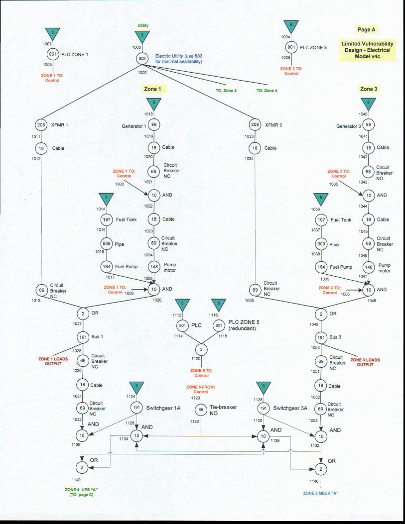
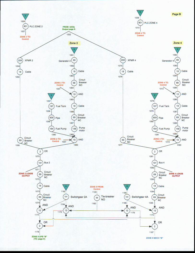
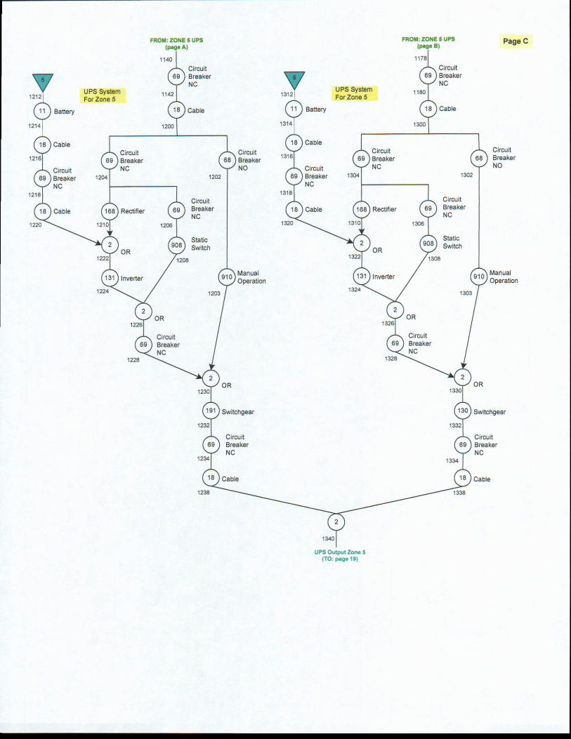
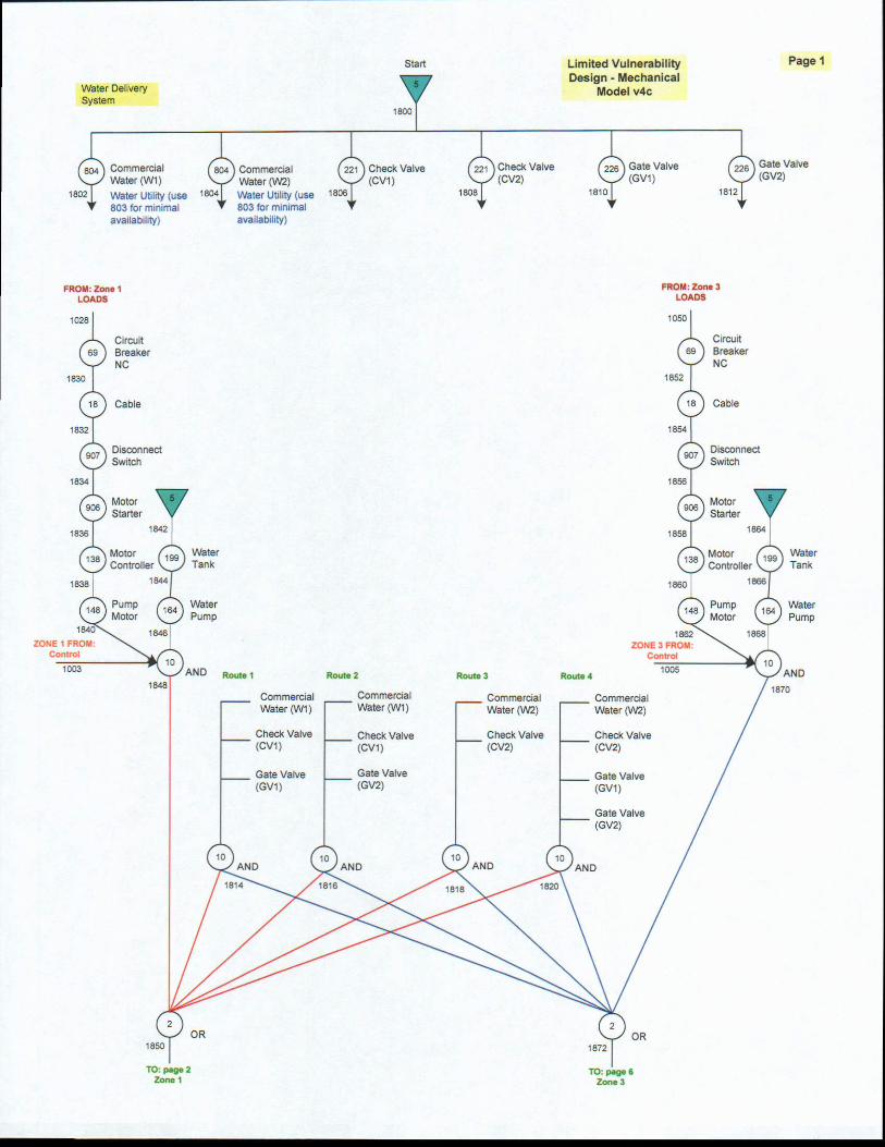
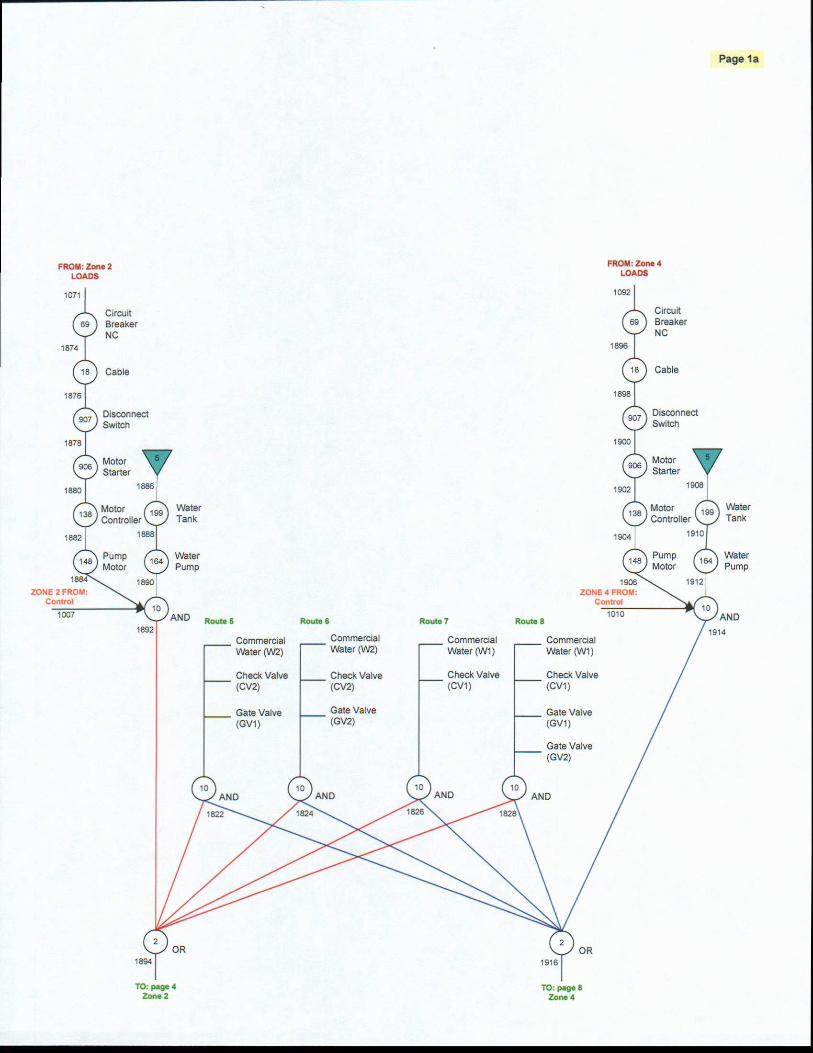
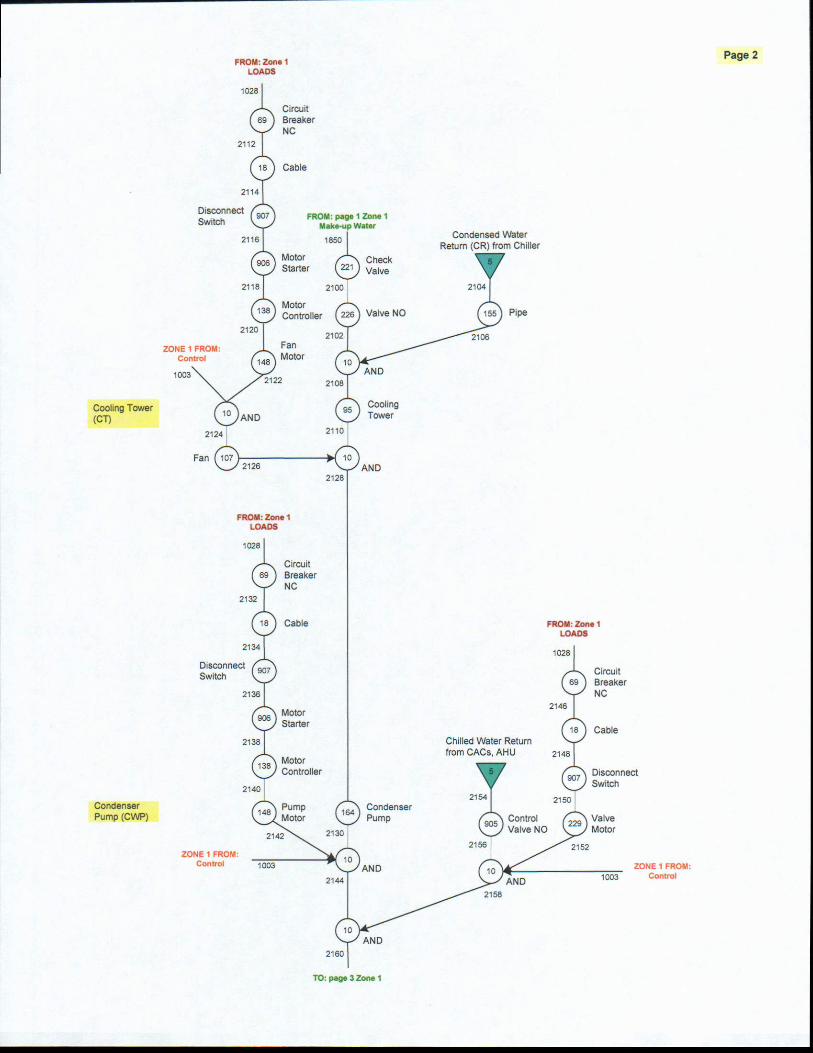


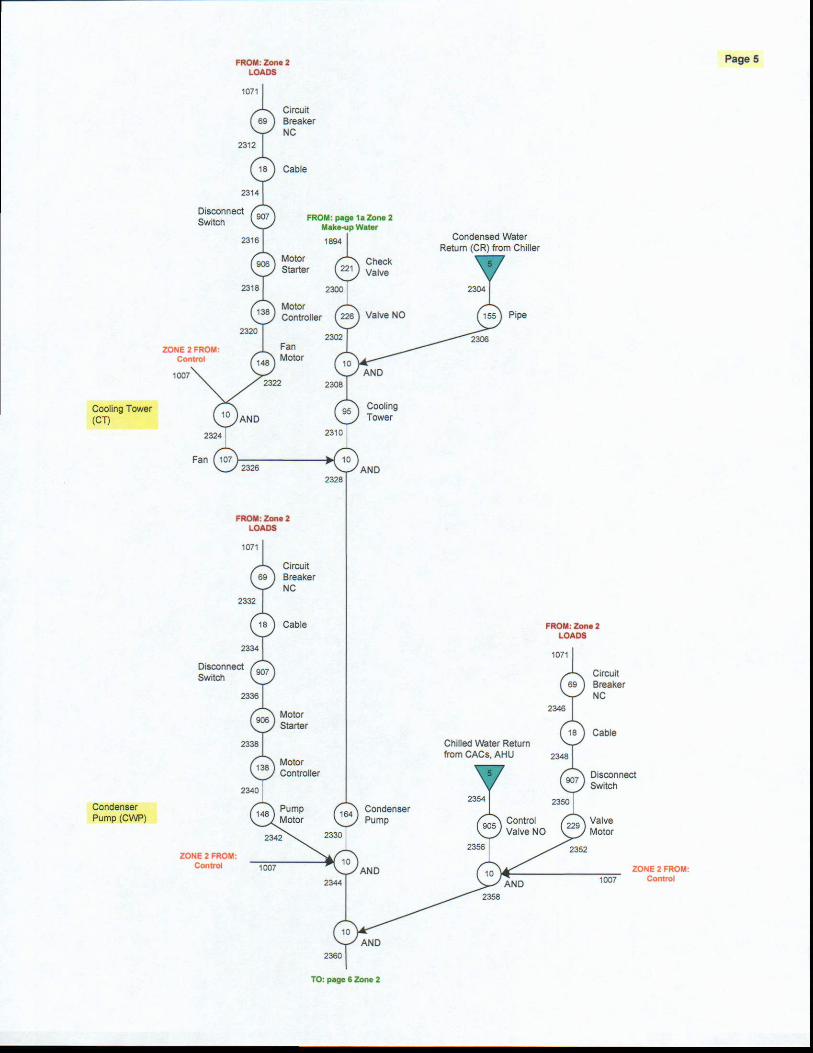
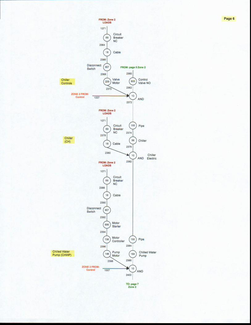
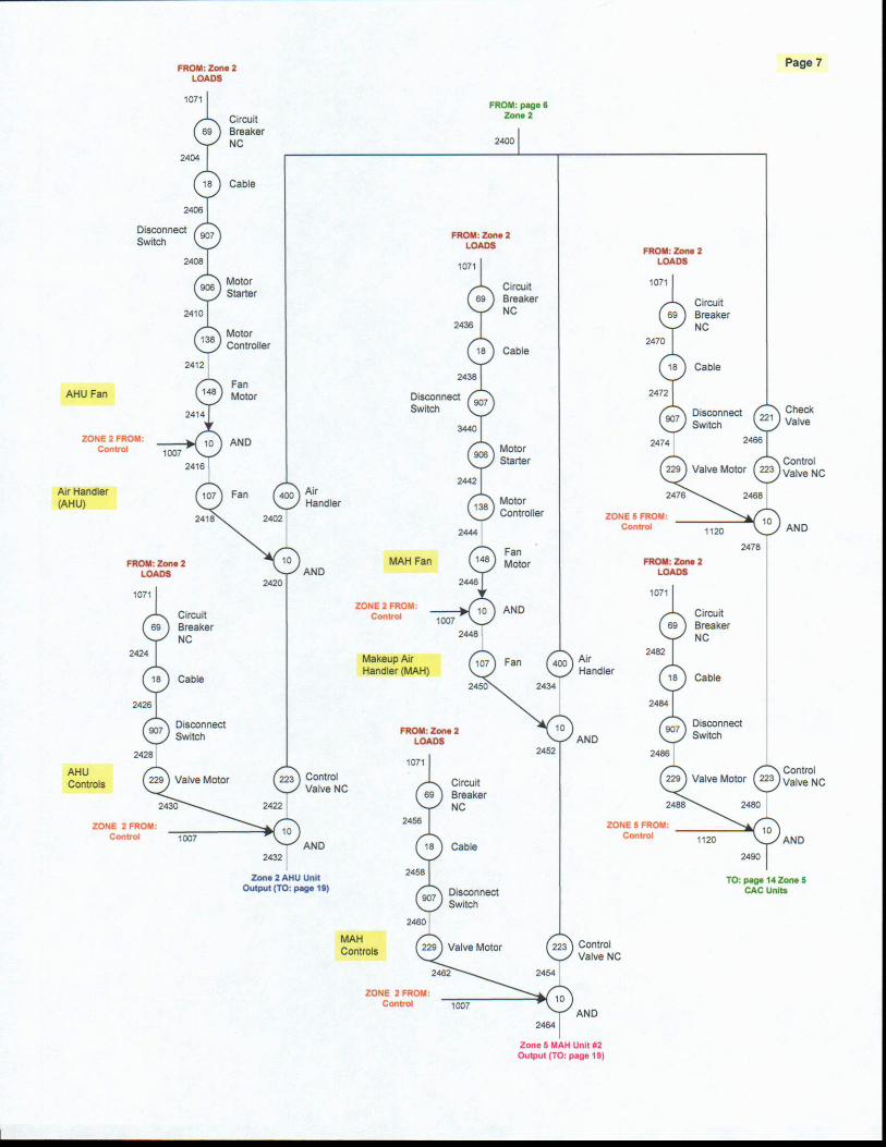

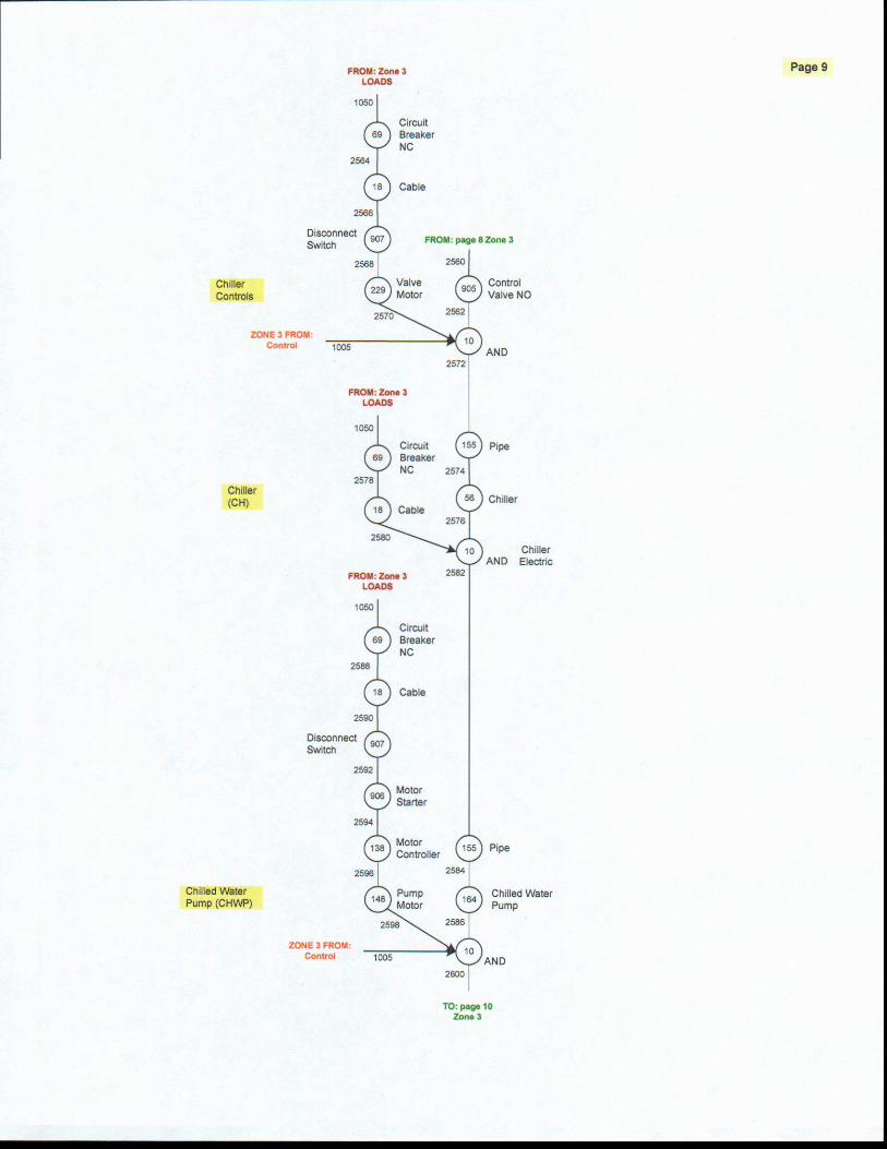


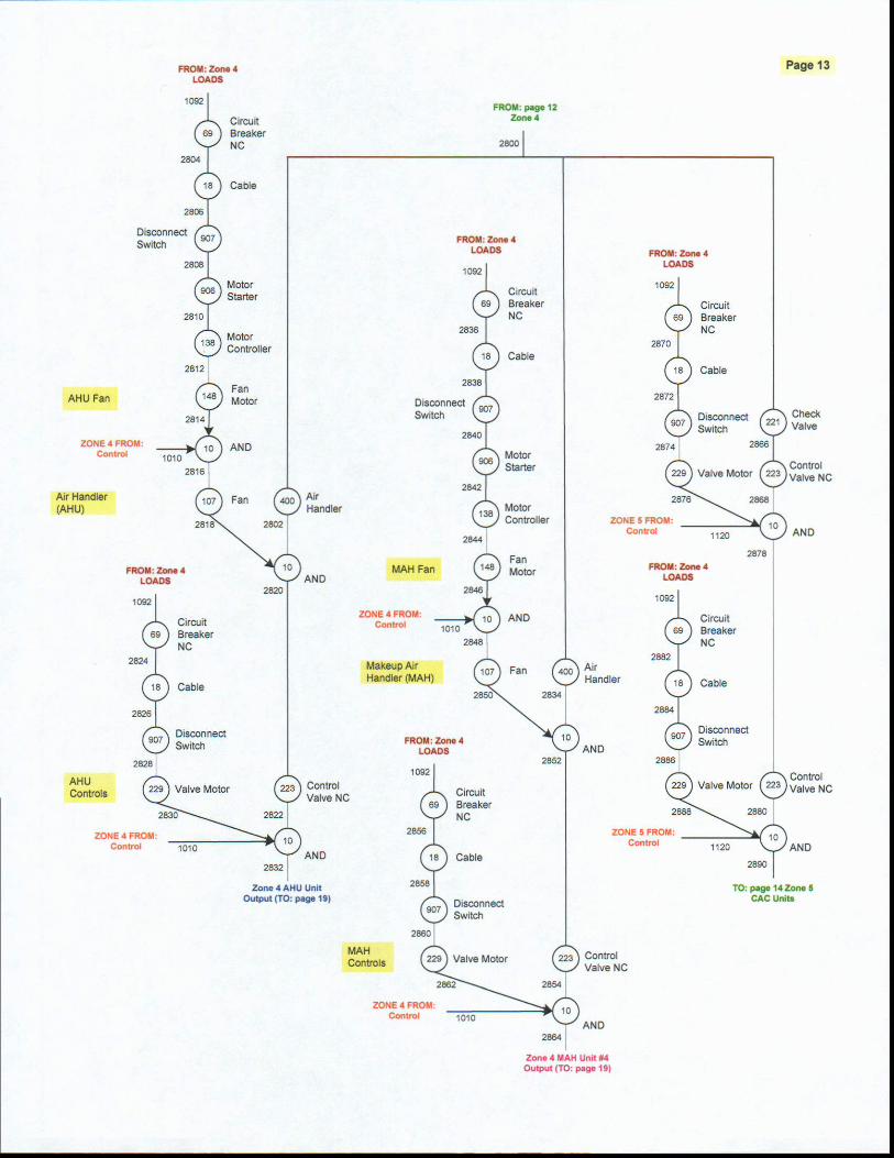


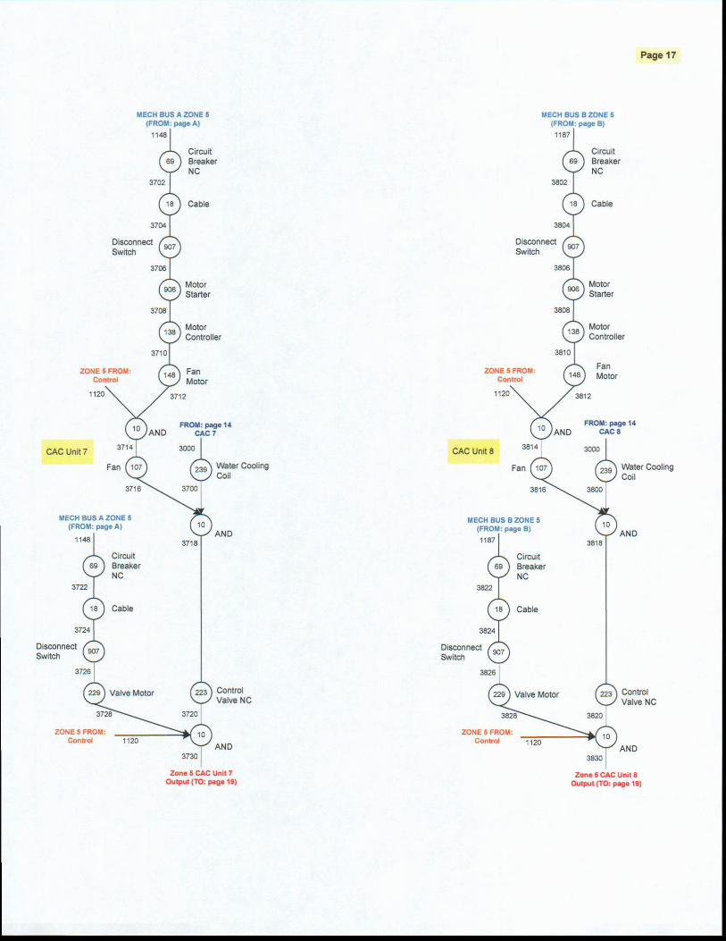
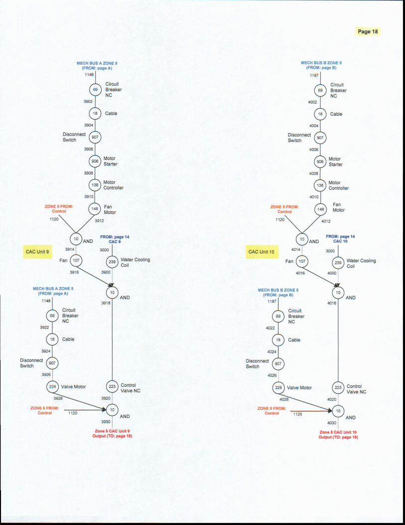


TM 5-602-1
D-1
APPENDIX D
EXAMPLE OF UTILITY CAPACITY CALCULATION
D-1 Applicability of this example This example is intended to illustrate the application of the redundancy and capacity criteria described in chapter 2, Fundamentals of Limited Vulnerability Design, to the selection of utility system capacity for a facility following the LVD concept. It is based solely on the example C4ISR facility, is limited to a sin-gle utility, and uses assumptions that are not valid for all facilities, missions, or geographic locations. Therefore, this should be considered an example only and not indicative of the utility requirements of any actual facility. The calculation below applies to the facility configuration described in chapter 3, Archi-tectural and Structural Systems, and presents a methodology for determining the required size of electrical services to meet the specified redundancy criteria. The facility consists of 35,000 GSF. The area is as-sumed to be divided approximately equally among the four peripheral zones and the command center. D-2 Calculation of required electrical capacity The required electrical capacity can be calculated as described below, using assumptions for the design loading of each zone. The capacity is calculated for the following two alternative configurations of the command center electrical system: a. Configuration 1 in figure D-1 is the simple automatic bus transfer scheme described in chapter 5, Electrical Systems. Each zone source must be capable of supplying 100 percent of the command center load. b. Configuration 2 as shown in figure D-2, is the command center is supplied by a ring bus with net-work protectors. With the greater redundancy of this scheme, each zone source must be capable of sup-plying only 50 percent of the command center load.

TM 5-602-1
D-2
Figure D-1. Single-line diagram – automatic transfer scheme
Figure D-2. Single-line diagram – ring bus with network protectors

TM 5-602-1
D-3
c. The calculation of the required electrical capacity consists of the following steps:
1. Calculate command center electrical load Upper level – people and consoles: 7,000 SF @ 25 W/SF = 175 kW Lower level – servers and communications gear: 7,000 SF @ 50 W/SF = 350 kW Total command center load: 525 kW
2. Calculate command center cooling load (525 kW x 3,412 Btu/kWhr)/12,000 Btu-hr/ton = 150 tons cooling
3. Calculate peripheral zone electrical load Office space – electronic-intensive use: 7,000 SF @ 10 W/SF = 70 kW Mechanical HVAC (estimated): 50 kW Total peripheral zone load: 120 kW
4. Calculate cooling capacity for each service Based on four peripheral zones, each must support itself and 50 percent of the command center load, as follows: Peripheral zone: 7,000 SF @ 200 SF/ton = 35 tons 50 percent of command center: 150 x 0.5 = 75 tons Required zone chiller capacity: 110 tons
5. Calculate electrical service capacity a. Configuration 1
Zone electrical load from step 3: 120 kW 100 percent of command center load from step 1: 525 kW Zone chilled water system: 110 tons x 1.0 kW/ton = 110 kW Total required service capacity: 755 kW
b. Configuration 2 Zone electrical load from step 3: 120 kW 50 percent of command center load from step 1: 263 kW Zone chilled water system: 110 tons x 1.0 kW/ton = 110 kW Total required service capacity: 493 kW
D-3. Additional considerations In this example, the more complex command center electrical configuration of figure D-2 reduces the re-quired capacity of each zone service by one-third. The designer would weigh these cost savings at the zone level against the increased cost of the switchgear at the command center level. In selecting a final design, the designer should also consider the potential risk of human error associated with the more com-plex configuration and the impact of such risk on reliability.
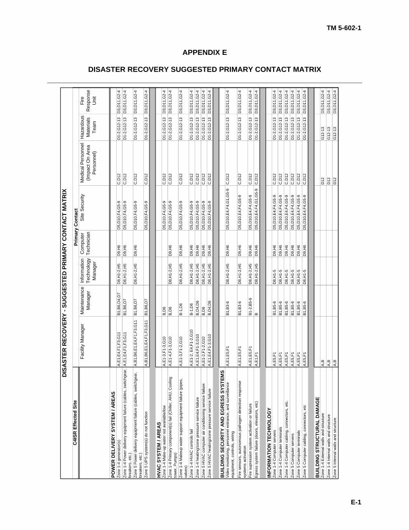
TM 5-602-1
E-1
APPENDIX E
DISASTER RECOVERY SUGGESTED PRIMARY CONTACT MATRIX
C4I
SR E
ffect
ed S
iteFa
cilit
y M
anag
erM
aint
enan
ce
Man
ager
Info
rmat
ion
Tech
nolo
gy
Man
ager
Com
pute
r Te
chni
cian
Site
Sec
urity
Med
ical
Per
sonn
el
(Impa
ct O
n Ar
ea
Pers
onne
l)
Haz
ardo
us
Mat
eria
ls
Team
Fire
R
espo
nse
Uni
t
POW
ER D
ELIV
ERY
SYST
EM /
AREA
SZo
ne 1
-4 g
ener
ator
(s)
A,E
1,E
4,F1
,F3,
G11
B1,B
6,D
4,D
7D
8,H
1-2,
H5
D9,
H6
D5,
D10
,F4,
G5-
9C
,D12
D1-
2,G
12-1
3D
3,D
11,G
2-4
Zone
1-4
Pow
er d
eliv
ery
equi
pmen
t fai
lure
(cab
les,
sw
itchg
ear,
brea
kers
, etc
.)A
,E1,
E4,
F1,F
3,G
11B1
,B6,
D7
D8,
H1-
2,H
5D
9,H
6D
5,D
10,F
4,G
5-9
C,D
12D
1-2,
G12
-13
D3,
D11
,G2-
4
Zone
5 P
ower
del
iver
y eq
uipm
ent f
ailu
re (c
able
s, s
witc
hgea
r, br
eake
rs, e
tc.)
A,B
1,B
6,E
1,E4
,F1,
F3,G
11B1
,B6,
D7
D8,
H1-
2,H
5D
9,H
6D
5,D
10,F
4,G
5-9
C,D
12D
1-2,
G12
-13
D3,
D11
,G2-
4
Zone
5 U
PS
sys
tem
(s) d
o no
t fun
ctio
n A
,B1,
B6,
E1,
E4,F
1,F3
,G11
B1,B
6,D
7D
5,D
10,F
4,G
5-9
C,D
12D
1-2,
G12
-13
D3,
D11
,G2-
4
HVA
C S
YSTE
M /
AREA
SZo
ne 1
-4 M
ake-
up w
ater
not
ava
ilabl
e/lo
wA
,E1-
3,F1
-3,G
10B,
D6
D5,
D10
,F4,
G5-
9C
,D12
D1-
2,G
12-1
3D
3,D
11,G
2-4
Zone
1-4
Prim
ary
com
pone
nt(s
) fai
l (C
hille
r, A
HU
, Coo
ling
tow
er, P
umps
)A
,E1-
4,F1
-3,G
10B,
D6
D8,
H1-
2,H
5D
9,H
6D
5,D
10,F
4,G
5-9
C,D
12D
1-2,
G12
-13
D3,
D11
,G2-
4
Zone
1-4
Mak
eup
wat
er s
uppo
rt eq
uipm
ent f
ailu
re (p
ipes
, va
lves
)A
,E1-
3,F1
-2,G
10B-
1,D
6D
8,H
1-2,
H5
D9,
H6
D5,
D10
,F4,
G5-
9C
,D12
D1-
2,G
12-1
3D
3,D
11,G
2-4
Zone
1-4
HV
AC
con
trols
fail
A,E
1-2,
E4,
F1-2
,G10
B-1,
D6
D8,
H1-
2,H
5D
9,H
6D
5,D
10,F
4,G
5-9
C,D
12D
1-2,
G12
-13
D3,
D11
,G2-
4Zo
ne 1
-4 h
eatin
g/zo
ne p
ress
ure
serv
ice
failu
reA
,E1,
E4,
F1-3
,G10
B,D
4,D
6D
8,H
1-2,
H5
D9,
H6
D5,
D10
,F4,
G5-
9C
,D12
D1-
2,G
12-1
3D
3,D
11,G
2-4
Zone
5 H
VA
C c
ompu
ter a
ir co
nditi
onin
g se
rvic
e fa
ilure
A,E
1-2,
F1-2
,G10
B,D
6D
8,H
1-2,
H5
D9,
H6
D5,
D10
,F4,
G5-
9C
,D12
D1-
2,G
12-1
3D
3,D
11,G
2-4
Zone
5 H
VA
C h
eatin
g/zo
ne p
ress
ure
serv
ice
failu
reA
,E1,
E4,
F1-3
,G10
B,D
4,D
6D
8,H
1-2,
H5
D9,
H6
D5,
D10
,F4,
G5-
9C
,D12
D1-
2,G
12-1
3D
3,D
11,G
2-4
BU
ILD
ING
SEC
UR
ITY
AND
EG
RES
S SY
STEM
SV
ideo
mon
itorin
g, p
erso
nnel
ent
ranc
e, a
nd s
urve
illanc
e eq
uipm
ent,
cont
rols
, wiri
ng
A,E
1,E
5,F1
B1,B
3-6
D8,
H1-
2,H
5D
9,H
6D
5,D
10,E
4,F4
,G1,
G5-
9C
,D12
D1-
2,G
12-1
3D
3,D
11,G
2-4
Fire
sen
sors
, aut
onom
ous
path
ogen
det
ectio
n re
spon
se
syst
ems
activ
atio
n A
,E1,
E5,
F1B1
,B3-
6D
8,H
1-2,
H5
D9,
H6
D5,
D10
,E4,
F4,G
5-9
C,D
12D
1-2,
G12
-13
D3,
D11
,G2-
4
Fire
sup
ress
ion
syst
em a
ctiv
atio
n or
failu
reA
,E1,
E5,
F1B1
-2,B
5-6
D8,
H1-
2,H
5D
9,H
6D
5,D
10,E
4,F4
,G5-
9C
,D12
D1-
2,G
12-1
3D
3,D
11,G
2-4
Egr
ess
syst
em fa
ilure
(doo
rs, e
leva
tors
, etc
)A
,E1,
F1B
D8,
H1-
2,H
5D
9,H
6D
5,D
10,E
4,F4
,G1,
G5-
9C
,D12
D1-
2,G
12-1
3D
3,D
11,G
2-4
INFO
RM
ATIO
N T
ECH
NO
LOG
YZo
ne 1
-4 C
ompu
ter s
erve
rsA
,E5,
F1B1
,B5-
6D
8,H
1-5
D9,
H6
D5,
D10
,E4,
F4,G
5-9
C,D
12D
1-2,
G12
-13
D3,
D11
,G2-
4Zo
ne 1
-4 C
ompu
ter t
erm
inal
sA
,E5,
F1B1
,B5-
6D
8,H
1-5
D9,
H6
D5,
D10
,E4,
F4,G
5-9
C,D
12D
1-2,
G12
-13
D3,
D11
,G2-
4Zo
ne 1
-4 C
ompu
ter c
ablin
g, c
onne
ctor
s, e
tc.
A,E
5,F1
B1,B
5-6
D8,
H1-
5D
9,H
6D
5,D
10,E
4,F4
,G5-
9C
,D12
D1-
2,G
12-1
3D
3,D
11,G
2-4
Zone
5 C
ompu
ter s
erve
rsA
,E5,
F1B1
,B5-
6D
8,H
1-5
D9,
H6
D5,
D10
,E4,
F4,G
5-9
C,D
12D
1-2,
G12
-13
D3,
D11
,G2-
4Zo
ne 5
Com
pute
r ter
min
als
A,E
5,F1
B1,B
5-6
D8,
H1-
5D
9,H
6D
5,D
10,E
4,F4
,G5-
9C
,D12
D1-
2,G
12-1
3D
3,D
11,G
2-4
Zone
5 C
ompu
ter c
ablin
g, c
onne
ctor
s, e
tcA
,E5,
F1B1
,B5-
6D
8,H
1-5
D9,
H6
D5,
D10
,E4,
F4,G
5-9
C,D
12D
1-2,
G12
-13
D3,
D11
,G2-
4
BU
ILD
ING
STR
UC
TUR
AL D
AMAG
EZo
ne 1
-4 E
xter
nal w
alls
and
stru
ctur
eA
,BD
12G
12-1
3D
3,D
11,G
2-4
Zone
1-4
Inte
rnal
wal
ls a
nd s
truct
ure
A,B
D12
G12
-13
D3,
D11
,G2-
4Zo
ne 5
Inte
rnal
wal
ls a
nd s
truct
ure
A,B
D12
G12
-13
D3,
D11
,G2-
4
Prim
ary
Con
tact
DIS
ASTE
R R
ECO
VER
Y - S
UG
GES
TED
PR
IMAR
Y C
ON
TAC
T M
ATR
IX
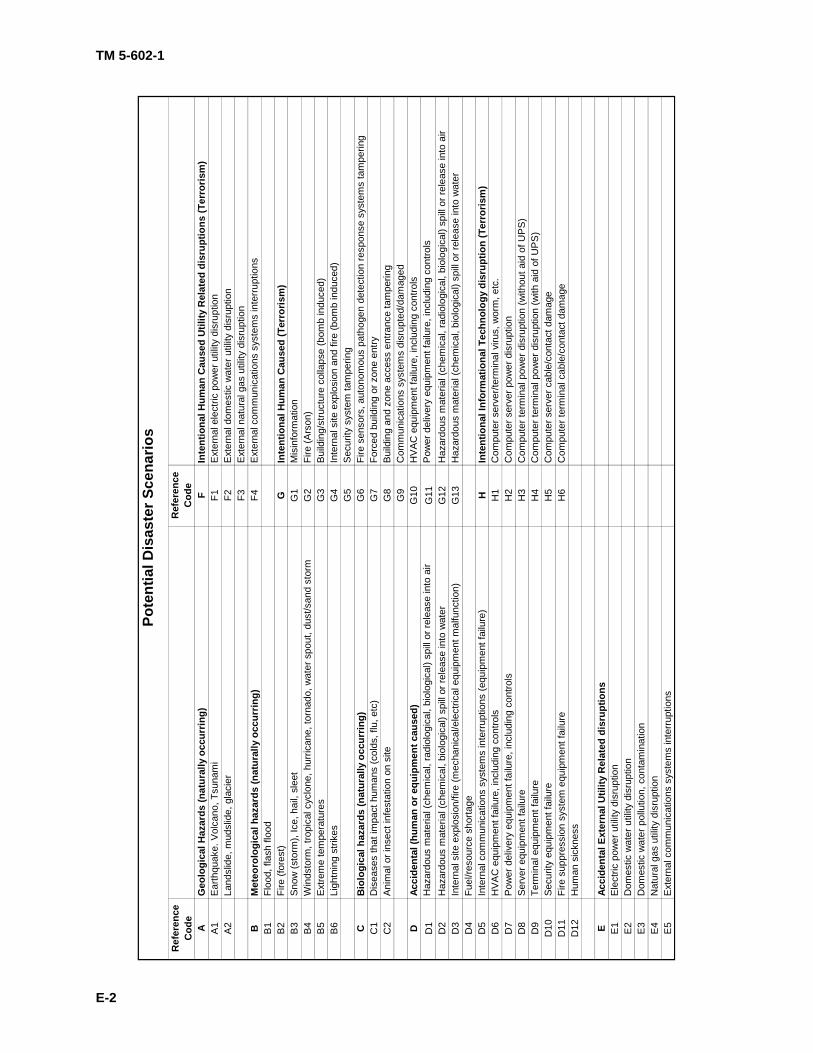
TM 5-602-1
E-2
Ref
eren
ce
Cod
eR
efer
ence
C
ode
AG
eolo
gica
l Haz
ards
(nat
ural
ly o
ccur
ring)
FIn
tent
iona
l Hum
an C
ause
d U
tility
Rel
ated
dis
rupt
ions
(Ter
roris
m)
A1
Ear
thqu
ake.
Vol
cano
, Tsu
nam
iF1
Ext
erna
l ele
ctric
pow
er u
tility
dis
rupt
ion
A2
Land
slid
e, m
udsl
ide,
gla
cier
F2E
xter
nal d
omes
tic w
ater
util
ity d
isru
ptio
nF3
Ext
erna
l nat
ural
gas
util
ity d
isru
ptio
nB
Met
eoro
logi
cal h
azar
ds (n
atur
ally
occ
urrin
g)F4
Ext
erna
l com
mun
icat
ions
sys
tem
s in
terr
uptio
nsB
1Fl
ood,
flas
h flo
odB
2Fi
re (f
ores
t)G
Inte
ntio
nal H
uman
Cau
sed
(Ter
roris
m)
B3
Sno
w (s
torm
), Ic
e, h
ail,
slee
tG
1M
isin
form
atio
nB
4W
inds
torm
, tro
pica
l cyc
lone
, hur
rican
e, to
rnad
o, w
ater
spo
ut, d
ust/s
and
stor
mG
2Fi
re (A
rson
)B
5E
xtre
me
tem
pera
ture
sG
3B
uild
ing/
stru
ctur
e co
llaps
e (b
omb
indu
ced)
B6
Ligh
tnin
g st
rikes
G4
Inte
rnal
site
exp
losi
on a
nd fi
re (b
omb
indu
ced)
G5
Sec
urity
sys
tem
tam
perin
gC
Bio
logi
cal h
azar
ds (n
atur
ally
occ
urrin
g)G
6Fi
re s
enso
rs, a
uton
omou
s pa
thog
en d
etec
tion
resp
onse
sys
tem
s ta
mpe
ring
C1
Dis
ease
s th
at im
pact
hum
ans
(col
ds, f
lu, e
tc)
G7
Forc
ed b
uild
ing
or z
one
entry
C2
Ani
mal
or i
nsec
t inf
esta
tion
on s
iteG
8B
uild
ing
and
zone
acc
ess
entra
nce
tam
perin
gG
9C
omm
unic
atio
ns s
yste
ms
disr
upte
d/da
mag
edD
Acci
dent
al (h
uman
or e
quip
men
t cau
sed)
G10
HV
AC
equ
ipm
ent f
ailu
re, i
nclu
ding
con
trols
D1
Haz
ardo
us m
ater
ial (
chem
ical
, rad
iolo
gica
l, bi
olog
ical
) spi
ll or
rele
ase
into
air
G11
Pow
er d
eliv
ery
equi
pmen
t fai
lure
, inc
ludi
ng c
ontro
lsD
2H
azar
dous
mat
eria
l (ch
emic
al, b
iolo
gica
l) sp
ill o
r rel
ease
into
wat
erG
12H
azar
dous
mat
eria
l (ch
emic
al, r
adio
logi
cal,
biol
ogic
al) s
pill
or re
leas
e in
to a
irD
3In
tern
al s
ite e
xplo
sion
/fire
(mec
hani
cal/e
lect
rical
equ
ipm
ent m
alfu
nctio
n)G
13H
azar
dous
mat
eria
l (ch
emic
al, b
iolo
gica
l) sp
ill or
rele
ase
into
wat
erD
4Fu
el/re
sour
ce s
horta
geD
5In
tern
al c
omm
unic
atio
ns s
yste
ms
inte
rrupt
ions
(equ
ipm
ent f
ailu
re)
HIn
tent
iona
l Inf
orm
atio
nal T
echn
olog
y di
srup
tion
(Ter
roris
m)
D6
HV
AC
equ
ipm
ent f
ailu
re, i
nclu
ding
con
trols
H1
Com
pute
r ser
ver/t
erm
inal
viru
s, w
orm
, etc
. D
7P
ower
del
iver
y eq
uipm
ent f
ailu
re, i
nclu
ding
con
trols
H2
Com
pute
r ser
ver p
ower
dis
rupt
ion
D8
Ser
ver e
quip
men
t fai
lure
H3
Com
pute
r ter
min
al p
ower
dis
rupt
ion
(with
out a
id o
f UP
S)D
9Te
rmin
al e
quip
men
t fai
lure
H4
Com
pute
r ter
min
al p
ower
dis
rupt
ion
(with
aid
of U
PS
)D
10S
ecur
ity e
quip
men
t fai
lure
H5
Com
pute
r ser
ver c
able
/con
tact
dam
age
D11
Fire
sup
pres
sion
sys
tem
equ
ipm
ent f
ailu
reH
6C
ompu
ter t
erm
inal
cab
le/c
onta
ct d
amag
eD
12H
uman
sic
knes
s
EAc
cide
ntal
Ext
erna
l Util
ity R
elat
ed d
isru
ptio
nsE
1E
lect
ric p
ower
util
ity d
isru
ptio
nE
2D
omes
tic w
ater
util
ity d
isru
ptio
nE
3D
omes
tic w
ater
pol
lutio
n, c
onta
min
atio
nE
4N
atur
al g
as u
tility
dis
rupt
ion
E5
Ext
erna
l com
mun
icat
ions
sys
tem
s in
terru
ptio
ns
Pote
ntia
l Dis
aste
r Sce
nario
s

TM 5-602-1
G-1
GLOSSARY
1. Glossary
-A- AGENT: A substance in the form of a toxic industrial chemical or toxic industrial material, biological or radiological agent, or military chemical, which together with the delivery tactic is a type of threat.
-C- COMMISSIONING: The process of verifying and documenting that the installed systems are in compli-ance with the design intent and specified performance criteria.
-D- DELIVERY TACTIC: The method of delivering a CBR agent (external or internal release). DESIGN BASIS THREAT: "The threat (aggressors, delivery tactics, and associated weapons, tools, or explosives) against which assets within the building must be protected and upon which the security engi-neering design of the building is based" (UFC 4-010-01).
-H- HYDRONIC: Of or relating to a system of heating or cooling that involves transfer of heat by a circulat-ing fluid in a closed system of pipes.
-I- INFILTRATION: The uncontrolled exchange of the building’s interior air with outside air.
-L-
LEVEL OF PROTECTION: The degree to which an asset is protected against injury or damage from a CBR event. LVD MODEL: A set of principles to apply in designing a C4ISR facility that is compartmentalized and provides multiple service pathways for all utilities to the critical load as protection against an internal ter-rorist attack intended to interrupt the mission.
-N- N+2: Pertaining to a system in which N units operating in parallel are required to supply the necessary capacity, with two additional or spare units provided so that maintenance activities and failures do not result in an inability to supply the required capacity. The same definition applies as the number of spare units is varied (N+1, N+3, etc.). 2N: Pertaining to a system in which N units operating in parallel are required to supply the necessary ca-pacity, with the number of units provided being double that.

TM 5-602-1
G-2
-S- STACK EFFECT: Thermally driven air density differences between the building indoor and outdoor ambient conditions.
-T-
THREAT: Aggressors, delivery tactics, and associated weapons, tools, or explosives against which a fa-cility is protected; established by evaluating aggressor likelihood and objectives with respect to the assets. TON: unit of refrigeration equal to 12,000 Btu per hour.
-V- VESICANT: a chemical that causes skin blisters.
TM 5-602-1 The proponent agency of this publication is the Chief of Engineers, United States Army. Users are invited to send comments and suggested improvements on DA Form 2028 (Recommended Changes to Publications and Blank Forms) directly to HQUSACE, (ATTN: CEMP-OS-P), Washington, DC 20314-1000.
Distribution:
To be distributed in accordance with Initial Distribution Number (IDN) 344777, requirements for non-equipment TM 5-602-1.
By Order of the Secretary of the Army:
PETER J. SCHOOMAKER General, United States Army
Chief of Staff Official:
SANDRA R. RILEY Administrative Assistant to the
Secretary of the Army

PIN: 083334-000