tm 5-2430-200-10
TRANSCRIPT

8/3/2019 TM 5-2430-200-10
http://slidepdf.com/reader/full/tm-5-2430-200-10 1/196

8/3/2019 TM 5-2430-200-10
http://slidepdf.com/reader/full/tm-5-2430-200-10 2/196

8/3/2019 TM 5-2430-200-10
http://slidepdf.com/reader/full/tm-5-2430-200-10 3/196
REMOVE PAGE
1 through 47 through 10
13 and 1417 through 22
27 and 2831 and 3235 through 42
45 and 4649 and 50
53 through 6265 through 88
97 and 98103 through 106109 through 118
121 through 132A-3 through A-6
A-15 and A-16
INSERT PAGE
A (B Blank)
1 through 47 through 10
13 and 1417 through 22
27 and 2831 and 3235 through 42
45 and 4649 and 50
53 through 6265 through 88
97 and 98103 through 106109 through 118
121 through 132A-3 and A-4
A-4.01 and A-4.02(blank)
A-5 and A-6A-15 and A-16
REMOVE PAGE
A-21 through A-24
B-1 and B-2C-1 through C-4
D-1 and D-2E-1 through E-6
INSERT PAGE
A-21 and A-21.00
A-21.01 and A- 22A-23 and 24
B-1 and B-2C-1 through C-4
D-1 and D-2E-1 and E-1.00E-1.01 Blank) and E-2
E-3 through E-6
TECHNICAL MANUAL
OPERATOR’S MANUALFOR
DEPLOYABLE UNIVERSAL
COMBAT EARTHMOVER (DEUCE)
30/30 (MODEL DV100)
NSN 2430-01-423-2819
PIN: 7RR00003-UP
DISTRIBUTION STATEMENT A - Approved for public release; distribution is unlimited.
TM 5-2430-200-10 dated 01 MARCH 2001 is updated as follows:
1. File this sheet in front of the manual for reference.2. This change is a result of various configuration changes and updates to include: recoil alert system, sight
gauge covers to rollers and rear idlers, changed and re-routed hydraulic hoses, updated PMCS, BII toolsand NSNs.
3. A vertical bar in the outer margin of the page or between columns in a double column format indicates newor updated text or illustrations.
4. Remove old pages and insert new pages as indicated below.
CHANGE
NO. 1
HEADQUARTERS, DEPARTMENT OF THE ARMY
WASHINGTON, DC, 18 MAY 2008
TM 5-2430-200-10
DA 2028 Sample DA 2028 Sample Front
None DA 2028 Sample Back
None DA 2028 Front and Back
Metric Chart Metric Chart
PIN PIN

8/3/2019 TM 5-2430-200-10
http://slidepdf.com/reader/full/tm-5-2430-200-10 4/196
By Order of the Secretary of the Army:
GEORGE W. CASEY, JR.
General, United States Army Chief of Staff
DISTRIBUTION: To be distributed in accordance with the Initial Distribution Number (IDN)256552, requirements for TM 5-2430-200-10.
JOYCE E. MORROW Administrative Assistant to the
Official:
Secretary of the Army
0811910

8/3/2019 TM 5-2430-200-10
http://slidepdf.com/reader/full/tm-5-2430-200-10 5/196
Page Number *Change Number
Cover...................................................................0A and B ...............................................................1Page 1 ................................................................1Page 2 and 3 ......................................................0Page 4.................................................................1Page 5 and 6 ......................................................0Page 7.................................................................1Page 8 ................................................................0Page 9 ................................................................1Page 10 through 12 ............................................0Page 13 ..............................................................1Page 14 through 17 ............................................0Page 18 through 22 ............................................1Page 23 through 26 ............................................0Page 27 and 28 ..................................................1Page 29 through 31 ............................................0Page 32...............................................................1
Page 33 and 34 ..................................................0Page 35...............................................................1Page 36 and 37 ..................................................0Page 38...............................................................1Page 39...............................................................0Page 40 through 42 ............................................1Page 43 through 45 ............................................0Page 46 ..............................................................1Page 47 through 49 ............................................0Page 50...............................................................1Page 51 through 53 ............................................0Page 54 through 58 ............................................1Page 59...............................................................0
Page 60 and 61 ..................................................1Page 62 through 64 ............................................0Page 65 through 67 ............................................1Page 68 ..............................................................0Page 69 through 71 ............................................1Page 72...............................................................0Page 73...............................................................1Page 74 and 75 .................................................0Page 76...............................................................1
Page Number *Change Number
Page 77...............................................................0Page 78 and 79 ..................................................1Page 80...............................................................0Page 81 through 84 ............................................1Page 85...............................................................0Page 86 ..............................................................1Page 87...............................................................0Page 88...............................................................1Page 89 through 97 ............................................0Page 98...............................................................1Page 99 through 102 ..........................................0Page 103 through 105 ........................................1Page 106 through 109 ........................................0Page 110 through 115 ........................................1Page 116.............................................................0Page 117 ............................................................1Page 118 through 121 ........................................0
Page 122 through 125 ........................................1Page 126.............................................................0Page 127 through 132 ........................................1Page A-1 through A-3 .........................................0Page A-4 .............................................................1Page A-4.01 (A-4.02 blank) ................................1Page A-5 .............................................................0Page A-6 ............................................................1Page A-7 through A-14 .......................................0Page A-15 and A-16 ..........................................1Page A-17 through A-20 ....................................0Page A-21 ...........................................................1Page A-21.00 and A-21.01 .................................1
Page A-22 ...........................................................0Page A-23 and A-24 ...........................................1Page B-1 .............................................................0Page B-2 .............................................................1Page C-1.............................................................0Page C-2 through C-4.........................................1Page D-1.............................................................0
A
TM5-2430-200-10
Change 1
INSERT LATEST CHANGED PAGES. DESTROY SUPERSEDED DATA.
LIST OF EFFECTIVE PAGES
NOTE: A vertical line in the outer margin of the page or between columns indicates the portion of the text orillustration affected by a change.
Dates of issue for original and changed pages are:Original 0 . . . . . . . . . 01 March 2001
Change 1. . . . . . . . .
18 May20
08TOTAL NUMBER OF CHANGE PAGES IS 89 WHICH CONSISTS OF THE FOLLOWING:
* A zero in the Change Number columns below indicates an original page.

8/3/2019 TM 5-2430-200-10
http://slidepdf.com/reader/full/tm-5-2430-200-10 6/196
BChange 1
Page Number *Change Number
Page D-2.............................................................1Page E-1 .............................................................1Page E-1.00 (E-1.01 blank) ................................1Page E-2 .............................................................1Page E-3 .............................................................0Page E-4 .............................................................1Page E-5 .............................................................0Page E-6 .............................................................1Page E-7 through F-2 .........................................0Authorization Page..............................................0
TM5-2430-200-10
LIST OF EFFECTIVE PAGES
DA 2028 Sample Front & Back ...................................1
DA 2028 Front & Back.................................................1
Metric Chart.................................................................1
PIN.............................................................................. 1w

8/3/2019 TM 5-2430-200-10
http://slidepdf.com/reader/full/tm-5-2430-200-10 7/196
1Information Section
Table of Contents
Table of Contents
Information Section
Foreword................................................................ ...3
Safety Section
Important Safety Information......................................4
Safety..................................................................... ...5Warning Labels .....................................................5General Hazard Information...................................9Crushing or Cutting Prevention............................10Burn Prevention ..................................................10Fire or Explosion Prevention ................................11 Threat of Nuclear, Biological, and Chemical (NBC)Contamination.................................................. ...12ElectroMagnetic Pulse (EMP) Exposure ...............12Mounting and Dismounting..................................12
Before Starting the Engine...................................12Engine Starting....................................................12Before Operating the Machine.............................13Machine Operation..............................................13Machine Parking .................................................13
General Section
Specifications and Model Views...............................14
Product Identification and Serial NumberLocations ............................................................15
Operation Section
Monitoring Systems and Cab Features ....................17
Machine Features ....................................................38
Equipment Controls.................................................50
Before Starting the Engine.......................................52
Engine Starting ........................................................54
After Starting Engine................................................60
Machine Operation ..................................................61
Operating Techniques..............................................73
Machine Parking......................................................76
Transportation Information .......................................79
Towing Information ..................................................85
Troubleshooting................................................... ....86
Maintenance Section
Cooling System Specifications.................................99
Fuel Specifications.................................................101
Lubricant Specifications.........................................102
Lubricant Viscosities and Refill Capacities..............103
Lubrication Chart ...................................................104
Maintenance Intervals ............................................105
When Required......................................................106
Every 10 Service Hours or Daily.............................112
Every 50 Service Hours or Weekly .........................125
Every 250 Service Hours or 3 Months ...................127
Index Section
Index .....................................................................129
TM 5-2430-200-10
Change 1
REPORTING ERRORS AND RECOMMENDING IMPROVEMENTS
You can help improve this publication. If you find any mistakes or if you know of a way to improve the procedures,please let us know. Submit your DA Form 2028 (Recommended Changes to Equipment Technical Publications),through the Internet, on the Army Electronic Product Support (AEPS) website. The Internet address ishttp://aeps.ria.army.mil. The DA Form 2028 is located under the Public Applications section in the AEPS Public
Home Page. Fill out the form and click on SUBMIT. Using this form on the AEPS will enable us to respond quickerto your comments and better manage the DA Form 2028 program. You may also mail, fax or email your letter, DAForm 2028 direct to: U. S. Army TACOM Life Cycle Management Command, ATTN: AMSTA-LC-LMPP/TECHPUBS, 1 Rock Island Arsenal, Rock Island, IL 61299-7630. The email address is [email protected]. The fax number is DSN 793-0726 or Commercial (309) 782-0726.

8/3/2019 TM 5-2430-200-10
http://slidepdf.com/reader/full/tm-5-2430-200-10 8/196
Appendices
A. Operator’s Preventive MaintenanceChecks and Services (OPMCS) –DEUCE
B. Components of End Item (COEI) –DEUCE
C. Basic Issue Items (BII) List—DEUCE
D. Additional Authorization List(AAL) – DEUCE
E. Unit Maintenance Level TransportationInformation
F. PLGR Instructions
2 TM 5-2430-200-10Information SectionTable of Contents

8/3/2019 TM 5-2430-200-10
http://slidepdf.com/reader/full/tm-5-2430-200-10 9/196
3TM5-2430-200-10Information Section
Foreword
Literature Information
This manual should be stored in the operator'scompartment. Store the manual in the pamphlet bag,which is provided as a Basic Issue Item (BII), or in theliterature storage area on the back side of theoperator’s seat.
This manual contains safety, operation, transportation,lubrication, and maintenance information suitable forthe Army operator.
Guards and covers may have been removed forillustrative purposes. Read, study and keep thismanual with the machine.
Whenever a question arises regarding your machine,or this publication, please consult U.S. Army Tank- Automotive and Armaments Command (TACOM), yourCaterpillar dealer, or Caterpillar Defense and FederalProducts for the latest available information.
Safety
The Safety section lists basic safety precautions. Inaddition, this section identifies the text and locationsof the warning signs and labels used on the machine.
Read and understand the basic precautions listed inthe Safety section before operating or performing anylubrication, maintenance or repair on this machine.
Operation
The Operation information is a reference for the newoperator and a refresher for the experienced one. Thissection includes a discussion of gauges, switches,machine controls, attachment controls, transportation,and towing information.
Photographs and illustrations guide the operatorthrough the correct procedures for checking, starting,operating and stopping the machine.
Maintenance The maintenance information is a guide to equipmentcare for Army operators. The illustrated, step-by-stepinstructions are grouped by servicing intervals. Itemswithout specific intervals are listed under the WhenRequired topics. Items in the Maintenance Intervalschart (refer to “Maintenance Section, MaintenanceIntervals” in this manual) are referenced to detailedinstructions that follow.
Maintenance Interval Schedule
Use the service hour meter to determine the servicingintervals. Calendar intervals shown (daily, weekly,monthly, etc.) can be used instead of the service hourmeter intervals, if they provide more convenientservicing schedules and approximate the indicatedservice hour meter reading. Recommended serviceshould always be performed at the interval that occursfirst.
Under extremely severe, dusty or wet operatingconditions, more frequent lubrication than is specifiedin the Maintenance Intervals chart might be necessary.
Perform service on items at multiples of the original
requirement. For example, at Every 50 Service Hoursor Weekly, also service those items listed under Every10 Service Hours or Daily.
Machine Description
The Deployable Universal Combat Earthmover(DEUCE) is an earthmoving machine capable of travelling between sites at high speed. The DEUCE isequipped with a 3126 HEUI (Hydraulic Electronic UnitInjector) engine that operates at two power levels, 197kW (265 hp) and 138 kW (185 hp). The machine isequipped with a power/angle/tilt (PAT) blade and awinch. The suspension on the machine can be
activated for smooth operation at high speed, orlocked, for a stable base when dozing.
California
Proposition 65 Warning
Diesel engine exhaust, and some of its constituents,are known to the state of California to cause cancer,birth defects, and other reproductive harm.
Foreword

8/3/2019 TM 5-2430-200-10
http://slidepdf.com/reader/full/tm-5-2430-200-10 10/196
4Safety SectionSafety
TM5-2430-200-10
Important Safety Information
Most accidents involving product operation, maintenance and repair are caused by failure to observebasic safety rules or precautions. An accident can often be avoided by recognizing potentiallyhazardous situations before an accident occurs. A person must be alert to potential hazards. This
person should also have the necessary training, skills and tools to perform these functions properly.
Improper operation, lubrication, maintenance or repair of this product can be dangerousand could result in injury or death.
Do not operate or perform any lubrication, maintenance or repair on this product, until youhave read and understood the operation, lubrication, maintenance and repair information.
Safety precautions and warnings are provided in this manual and on the product. If these hazardwarnings are not heeded, bodily injury or death could occur to you or other persons.
The hazards are identified by the “Safety Alert Symbol” and followed by a “Signal Word” such as“WARNING” as shown below.
The meaning of this safety alert symbol is as follows:
Attention! Become Alert! Your Safety is Involved.
The message that appears under the warning, explaining the hazard, can be either written orpictorially presented.
NOTICEOperations that may cause product damage are identified by NOTICE labels on the product and inthis publication.
Caterpillar cannot anticipate every possible circumstance that might involve a potential hazard. Thewarnings in this publication and on the product are therefore not all inclusive. If a tool, procedure,work method or operating technique not specifically recommended by Caterpillar is used, you mustsatisfy yourself that it is safe for you and others. You should also ensure that the product will not bedamaged or made unsafe by the operation, lubrication, maintenance or repair procedures youchoose.
The information, specifications, and illustrations in this publication are on the basis of informationavailable at the time it was written. The specifications, torques, pressures, measurements,adjustments, illustrations, and other items can change at any time. These changes can affect theservice given to the product. Obtain the complete and most current information before starting any job. TACOM and Caterpillar dealers will have the most current information available. For a list of the
most current publication form numbers available, see the Caterpillar Service Manual ContentsMicrofiche, REG1139F.
WARNING!
Change 1

8/3/2019 TM 5-2430-200-10
http://slidepdf.com/reader/full/tm-5-2430-200-10 11/196
Warning Labels
There are several specific warning labels on thismachine. The exact location of each label and adescription of the hazard are reviewed in this section.Please review the location and content of eachwarning label.
NOTE: The warning labels on the radiator and enginevalve covers are not accessible to the operator
Make sure all warning labels can be read. Clean orhave the warning labels replaced if the words cannotbe read, or the illustrations are not clear. Whencleaning the warning labels, use a cloth, water, andsoap. Do not use solvent, gasoline, etc., to clean the
warning labels. Solvents or gasoline, etc., couldloosen the label adhesive and allow the sign to fall off.
If a warning label is attached to a part that is replaced,make sure a new label is installed on the replacedpart. Contact TACOM or any Caterpillar dealer for newwarning labels. Refer to the following group numbersin Parts Manual, Deployable Universal Combat Earthmover (DEUCE) for the part numbers of thewarning labels and data plates:
• 1004943 Cover GP-Valve Mechanism• 1228811 Paint GP-Transfer• 1243842 Cylinder GP & Mounting (Front)• 1243847 Cylinder GP & Mounting (Bogie)• 1450425 Cab GP-Basic• 1520463 Wiring GP & Battery (Optional Arctic)
Improper jumper cable connections can causeexplosion, resulting in personal injury.
Batteries may be located in separatecompartments. When using jumper cables,always connect positive (+) cable to positive (+)terminal of battery connected to starter solenoidand negative (-) cable from external source tostarter negative (-) terminal. (If machine notequipped with starter negative terminal, connectto engine block.) Follow procedure in theoperation manual.
Warning label (1) is located inside the batterycompartment, at the rear of the machine.
A second copy of warning label (1) is located on theleft side of the machine, towards the rear, near theauxiliary start receptacle (NATO slave).
A third copy of warning label (1) is located on thearctic battery box, if the machine is equipped with thearctic battery option.
1
1
1
WARNING!
Safety
5Safety Section
Safety
TM5-2430-200-10

8/3/2019 TM 5-2430-200-10
http://slidepdf.com/reader/full/tm-5-2430-200-10 12/196
Pressurized system: hot coolant can cause seriousburn. To open cap, stop engine, wait until radiator iscool, then loosen cap slowly to relieve the pressure.
Warning label (2) is located on the radiator, near thecap.
• If a load slips or falls—you can be injured orkilled.
• Always be alert when around moving oroverhead loads.
• Always keep hands and body away from blocksheaves and swivels—and away from “pinchpoints” where rope touches block parts.
• Always inspect tackle block system and partsbefore each use.
• See OSHA Rule 1926 550(G) for personnelhoisting for cranes and derricks. Only a Crosbyor McKissick Hook with a PL latch attached andsecured with the bolt, nut and cotter pinprovided, may be used. For any personnelhoisting, a hook with or without a Crosby Ss-4055 Latch attached shall not be used forpersonnel hoisting.
• Never use tackle block without properinstruction and training.
• Only use proper component parts.
Warning label (3) is located on the winch doublingblock.
3
WARNING!
2
WARNING!
6Safety SectionSafety
TM5-2430-200-10

8/3/2019 TM 5-2430-200-10
http://slidepdf.com/reader/full/tm-5-2430-200-10 13/196
Warning label (4) is located on the engine valve cover. This warning label is a four-quadrant graphic label.
Quadrant (5) warns against injecting ether into the airintake system. Quadrant (6) warns of an electricalshock hazard. Quadrant (7) warns that damaged high-pressure oil lines can cause injury. Quadrant (8) directspersonnel to read the service manual beforeperforming service on the engine.
The protection offered by this ROPS will beimpaired if it has been subjected to anymodification, structural damage, or has beeninvolved in an overturn incident. This ROPS must
be replaced after a roll-over. Seat belts must beworn while operating vehicle.
Warning label (9) is located on the top right corner of the cab, inside the operator’s compartment.
NOTE: ROPS is the acronym for Rollover ProtectiveStructure.
Do not operate or work on this machine unlessyou have read and understand the instructionsand warnings in the operation and maintenancemanuals. Failure to follow the instructions orheed the warnings could result in injury or deathContact any Caterpillar dealer for replacementmanuals. Proper care is your responsibility.
Warning label (10) is located on the console to theright of the operator’s seat.
10
WARNING!
9
WARNING!
4 5 6
87
7Safety Section
Safety
TM5-2430-200-10
Change 1

8/3/2019 TM 5-2430-200-10
http://slidepdf.com/reader/full/tm-5-2430-200-10 14/196
If NBC exposure is suspected all air filter mediawill be handled by personnel wearing full NBCprotective equipment. See operator maintenancemanuals. Failure to comply could result inserious illness or death.
Warning label (11) is located at all air filter locations.
NOTE: NBC is an acronym for nuclear, biological, orchemical.
High intensity noise. Hearing protection requiredwithin 33 feet when operating.
Warning label (12) is located on the left side of themachine, to the rear of the cab door.
12
WARNING!
11
11
11
WARNING!
8Safety SectionSafety
TM5-2430-200-10

8/3/2019 TM 5-2430-200-10
http://slidepdf.com/reader/full/tm-5-2430-200-10 15/196
Accumulator and connecting lines may bepressurized.
Read and follow the maintenance manual and theinstructions below before working on theaccumulator and connecting lines.
Failure to follow the maintenance manual or theinstructions can cause rapid discharging of gasor hydraulic fluids which can result in injury ordeath.
1. Slowly bleed all hydraulic pressure off the
hydraulic side of the accumulators by using thehydraulic disconnects.
2. Slowly discharge all gas pressure by openinggas valve at one end of the accumulator until gasbegins to escape. Wait until all gas pressure isrelieved before proceeding with nextmaintenance procedure.
(13) Brake accumulator, beneath cab. (14) Front cylinderaccumulator, each side of machine. (15) Middle cylinderaccumulator, each side of machine. (16) Bogie cylinderaccumulator, each side of machine. (17) Recoil accumulator,each side of machine. (18) Kneeling accumulator, each side ofmachine.
Accumulator warning labels are attached to eachaccumulator on the machine.
General Hazard Information
Attach a Do Not Operate warning tag to the startswitch or controls before servicing or repairing themachine. This tag is available from TACOM.
Know the width of your attachments so that properclearance can be maintained when operating nearfences, boundary obstacles, etc.
Wear a hard hat, protective glasses, and otherprotective equipment as required by job conditions.
Wear eye and face protection when working withhydraulic or air lines.
Do not wear loose clothing or jewelry that can catchon the controls, or other parts of the machine.
Make certain that all protective guards and covers aresecured in place on the machine.
Keep the machine, especially the deck, walkways andsteps, free of foreign material; such as debris, oil, toolsand other items which are not part of the machine.
Secure all loose items such as tools and other itemswhich are not part of the machine.
Know the appropriate work site hand signals and whogives them. Accept signals from one person only.
Do not smoke when servicing air conditioners orwherever refrigerant gasses may be present. Inhalingair-conditioner refrigerant gas through a lit cigarette orother smoking method or inhaling fumes released froma flame contacting air-conditioner refrigerant gas cancause bodily harm or death.
Never put maintenance fluids into glass containers.
Drain all liquids into a suitable container. Dispose of allliquids according to local regulations.
Use all cleaning solutions with care.
Report all needed repairs.
Do not allow unauthorized personnel on the machine.
Do not operate the engine coolant heater whilerefueling the machine. Do not place any combustibleor heat sensitive material within 50.8 mm (2 in) of theheater’s exhaust system. Routinely inspect the fueldelivery system for leaks. Repair all leaks before
operating the heater. Operation of the heaterproduces harmful vapors which represent anasphyxiation hazard. To guard against asphyxiation:do not operate the heater in an enclosed space;ensure that no exhaust fumes enter the operator’scompartment. Exhaust components can be extremelyhot. Do not touch the exhaust components until theparts are cool.
13 14 15
16 17 18
WARNING!
9Safety Section
Safety
TM5-2430-200-10
Change 1

8/3/2019 TM 5-2430-200-10
http://slidepdf.com/reader/full/tm-5-2430-200-10 16/196
Performance of Maintenance
Unless otherwise specified, maintenance should beperformed with the machine parked on level ground,the blade resting on the ground, the transmissioncontrol lever in NEUTRAL, the parking brake engaged,the engine stopped, and the electrical disconnectswitch in the OFF position.
Pressure Air
Pressure air can cause personal injury. When usingpressure air for cleaning, wear a protective face shield,protective clothing, and protective shoes.
The maximum air pressure must be below 205 kPa
(30 psi) for cleaning purposes.
Fluid Penetration
Always use a board or cardboard when checking for aleak. Escaping fluid under pressure, even a pin-holesize leak, can penetrate body tissue, causing seriousinjury, and possible death. If fluid is injected into yourskin, it must be treated immediately by a doctorfamiliar with this type of injury.
Crushing or Cutting Prevention
Support equipment and attachments properly when
working beneath them. Do not depend on hydrauliccylinders to hold them up. Any attachment can fall if acontrol is moved, or if a hydraulic line breaks.
Never attempt adjustments while the machine ismoving, or the engine is running, unless otherwisespecified.
Where there are attachment linkages, the clearance inthe linkage area will increase or decrease withmovement of the attachment.
Stay clear of all rotating and moving parts.
Keep objects away from moving fan blades. They willthrow or cut any object or tool that falls, or is pushed,into them.
Do not use a kinked or frayed wire rope cable. Weargloves when handling the wire rope cable.
Retainer pins, when struck with force, can fly out andinjure nearby persons. Make sure the area is clear of people when driving retainer pins.
Wear protective glasses when striking a retainer pin,to avoid injury to your eyes.
Chips, or other debris, can fly off objects when struck.Make sure no one can be injured by flying debris
before striking any object.
Rollover Protective Structure (ROPS) orFalling Objects Protective Structure (FOPS)
ROPS or FOPS are guards located above theoperator's compartment and secured to the machine.
To avoid any possible weakening of the ROPS orFOPS, consult TACOM or any Caterpillar dealer beforealtering, adding weight to, welding on, or cutting ordrilling holes into the structure.
Any alteration not specifically authorized by Caterpillar
invalidates Caterpillar's ROPS and FOPS certification. The protection offered by the ROPS/FOPS will beimpaired if it has been subjected to structural damage.Structural damage can be caused by an overturnaccident, by falling objects, etc.
Burn Prevention
Coolant
At operating temperature, the engine coolant is hotand under pressure. The radiator and all lines toheaters, or the engine, contain hot coolant or steam. Any contact can cause severe burns.
Steam can cause personal injury.
Check the coolant level only after the engine has beenstopped and the fill cap is cool enough to remove withyour bare hand.
Remove the cooling system fill cap slowly to relievepressure.
Cooling system additive contains alkalis that cancause personal injury. Avoid contact with the skin,eyes, and mouth.
Allow cooling system components to cool beforedraining.
Oils
Hot oil and components can cause personal injury. Donot allow hot oil or components to contact the skin.
At operating temperature, the hydraulic tank is hot andcan be under pressure.
10Safety SectionSafety
TM5-2430-200-10
8/3/2019 TM 5-2430-200-10
http://slidepdf.com/reader/full/tm-5-2430-200-10 17/196
Remove the hydraulic tank fill cap only after the enginehas been stopped, and the fill cap is cool enough to
remove with your bare hand.
Remove the hydraulic tank fill cap slowly, to relievepressure.
Relieve all pressure in air, oil, fuel, or cooling systemsbefore any lines, fittings or related items aredisconnected or removed.
Batteries
Batteries give off flammable fumes which can explode.
Do not smoke when observing the battery electrolyte
levels.
Electrolyte is an acid and can cause personal injury if itcontacts the skin or eyes.
Always wear protective glasses when working withbatteries.
Fire or Explosion Prevention
All fuels, most lubricants, and some coolant mixturesare flammable.
Fuel leaked, or spilled, onto hot surfaces or electrical
components can cause a fire.
Do not smoke while refueling or while in a refuelingarea.
Do not smoke in areas where batteries are charged,or where flammable materials are stored.
Refer to “Operation Section, Engine Starting” in thismanual for specific starting instructions.
Clean and tighten all electrical connections. Check daily for loose or frayed electrical wires. Have all looseor frayed electrical wires tightened, repaired, orreplaced before operating the machine.
Keep all fuels and lubricants stored in properly markedcontainers and away from all unauthorized persons.
Store all oily rags, or other flammable material, inprotective containers.
Do not weld or flame cut on pipes or tubes thatcontain flammable fluids. Clean them thoroughly with anonflammable solvent before welding or flame cuttingon them.
Remove all flammable materials such as fuel, oil andother debris before they accumulate on the machine.
Do not expose the machine to flames, burning brush,etc., if at all possible.
Shields, which protect hot exhaust components fromoil or fuel spray in the event of a line, tube or sealfailure, must be installed correctly.
Fire Extinguisher
Have a fire extinguisher available and know how touse it. Inspect and have it serviced as recommendedon its instruction plate.
Make sure the fire extinguisher is mounted on the rightside fender at the rear of the machine, in the locationprovided.
Ether
Ether is poisonous and flammable.
Inhaling ether vapors, or the repeated contact of etherwith skin, can cause personal injury.
Use ether only in well-ventilated areas.
Do not smoke while changing ether cylinders.
Use ether with care to avoid fires.
Do not store replacement ether cylinders in livingareas or in the operator's compartment.
Do not store ether cylinders in direct sunlight or attemperatures above 40°C (102°F).
Discard the cylinders in a protective place. Do notpuncture or burn the cylinders.
Keep ether cylinders out of the reach of unauthorizedpersonnel.
Lines, Tubes and Hoses
Do not bend or strike high pressure lines. Do notinstall bent or damaged lines, tubes or hoses.
Repair any loose or damaged fuel and oil lines, tubesand hoses. Leaks can cause fires.
11Safety Section
Safety
TM5-2430-200-10
8/3/2019 TM 5-2430-200-10
http://slidepdf.com/reader/full/tm-5-2430-200-10 18/196
Check all lines, tubes and hoses carefully. Do not useyour bare hand to check for leaks. Use a board or
cardboard to check for leaks. Refer to “Safety, FluidPenetration” in this section for more details. Tighten allconnections to the recommended torque. Replace if any of the following conditions are found:
• End fittings are damaged or leaking.
• Outer covering is chafed or cut, and the wirereinforcing is exposed.
• Outer covering is ballooning locally.
• There is evidence of kinking, or crushing, of theflexible part of the hose.
• Hose armor is embedded in the outer cover.
• End fittings are displaced.
Make sure that all clamps, guards and heat shields areinstalled correctly, to prevent vibration, rubbing againstother parts, and excessive heat during operation.
Threat of Nuclear, Biological, andChemical (NBC) Contamination
The DEUCE incorporates a CARC painted exterior. The materials used in the DEUCE are metal, rubber,
plastic, fabric and glass. In the event of NBCcontamination, the decontaminates for these surfacesand materials are listed in Army FM 3-5. Fordecontamination procedures, refer to Army FM 3-7. The DEUCE Parts Manual, TM5-2430-200-24P,contains a list of parts that are susceptible to damagefrom NBC exposure.
ElectroMagnetic Pulse (EMP) Exposure
The components listed and designated as EMPsusceptible may be damaged by EMP exposure. If themachine is exposed to an EMP incident, verify properoperation and repair as necessary. The DEUCE Parts
Manual, TM5-2430-200-24P, contains a list of partsthat are susceptible to damage from EMP exposure.
Mounting and Dismounting
This machine can be mounted or dismounted at theleft front of the machine.
• Mount and dismount the machine only on the leftside, where steps and hand holds are provided.
• Inspect, and when necessary, clean and haverepairs made to the steps and hand holds before
mounting and dismounting.
• Face the machine when mounting and dismounting.
• Maintain a three-point contact (two feet and onehand or one foot and two hands) with the steps andhand holds.
• Never get on or off a moving machine.
• Never jump off the machine.
• Do not try to climb on or off the machine whencarrying any tools or supplies. Use a hand line to
pull any equipment up onto the platform.
• Do not use any controls as hand holds whenentering or leaving the operator's station.
• Always raise and then use the handrail when on thewalkways.
• Keep the walkways free of debris and oil. Cleanaway any ice or snow that has accumulated.
Alternate Exit
This machine is equipped with an alternate exit. Foradditional alternate exit information, refer to “OperationSection, Monitoring Systems and Cab Features” in thismanual.
Before Starting the Engine
Start the engine only from the operator's station.Never short across the starter terminals or across thebatteries, as this could bypass the engine neutral-startsystem, as well as damage the electrical system.
Before starting the engine, refer to “Operation Section,Before Starting the Engine” in this manual.
Engine StartingDo not start the engine or move any of the controls if there is a Do Not Operate or similar warning tagattached to the start switch or controls.
Diesel engine exhaust contains products of combustion which can be harmful to your health. Always start and operate the engine in a well-ventilated area. If the machine is in an enclosed area,vent the exhaust to the outside.
12Safety SectionSafety
TM5-2430-200-10

8/3/2019 TM 5-2430-200-10
http://slidepdf.com/reader/full/tm-5-2430-200-10 19/196
This machine will spot turn with the engine running,even though the transmission control is in NEUTRAL.
Always apply the parking brake while starting theengine.
To start the engine, refer to the procedures given in“Operation Section, Engine Starting” in this manual.
Before Operating the Machine
Clear all personnel from the machine and the area.
Clear all obstacles from the path of the machine.Beware of hazards such as wires, ditches, etc.
If radio antennas are installed, ensure that none of the
antennas will contact electrical wires when themachine is operated. If clearance is not sufficient, tiethe antennas down to avoid contact with electricalwires.
Be sure all windows are clean. Secure the doors andwindows in either the open or shut position.
Adjust the rear view mirrors for best vision, especiallyclose to the machine.
Make sure the machine horn, the back-up alarm andall other warning devices are working properly.
Adjust the tilt and length of the steering column sothat it is best suited for operating the machine.
Fasten the seat belt securely.
Before operating this machine, read and understandthe information given in the “Operation Section” of thismanual.
Machine Operation
Operate the machine only while seated and with theseat belt fastened.
To minimize whole body vibration, based on 24 houroperations, limit daily machine usage to a maximum of 11.5 hours, no more than 4 hours continuous; theoperator must rest between operations at least 4.16hours.
Operate the controls only with the engine running,unless instructed otherwise.
The operator must be satisfied that no one will beendangered before moving the machine.
Do not allow riders on the machine.
Report any needed repairs noted during operation.
Stay a safe distance from the edge of cliffs, overhangsand slide areas.
If the machine begins to side slip on a grade,immediately turn the machine downhill.
Be careful to avoid any condition which could lead totipping when working on hills, banks or slopes, andwhen crossing ditches, ridges or other obstructions.Whenever possible, work up and down slopes, ratherthan sideways.
Keep the machine under control and do not work itover its capacity.
Be sure any hitch points and the towing device areadequate.
Never straddle a wire rope cable or similar device, norallow others to do so.
Know the maximum height and reach of yourmachine.
Always keep the ROPS (the top half of the cab shell)installed when operating the machine.
Always remove the ROPS (the top half of the cabshell) when preparing the machine for air drop.
Always kneel the machine and install the kneeling lockpins when driving and parking the machine in atransport airplane.
When operating this machine, follow the proceduresand heed the warnings given in the “OperationSection” of this manual.
Machine Parking
Park the machine on level ground, with the bladeresting on the ground, the transmission control lever inNEUTRAL, and the parking brake engaged. Block the
drive belts (on downhill side) if the machine must beparked on uneven terrain. Move the electricaldisconnect switch into the OFF position after parkingthe machine and stopping the engine.
For detailed parking instructions, refer to “OperationSection, Machine Parking” in this manual.
13Safety Section
Safety
TM5-2430-200-10
Change 1

8/3/2019 TM 5-2430-200-10
http://slidepdf.com/reader/full/tm-5-2430-200-10 20/196
(1) Cab. (2) Cooling system. (3) Air filter compartment. (4) Fueltank. (5) Blade. (6) Back ripper. (7) Front idler. (8) Rear idler.(9) Drive wheel.
(10) Hydraulic oil tank. (11) Oil filter compartment. (12) Recoilcylinder. (13) Midroller.
(14) Electrical panel and BII compartment. (15) Tool/batterycompartment. (16) Optional arctic battery box. (17) Backup alarm.(18) Winch. (19) Pintle hook.
NOTE: If the machine is equipped with the optionalarctic starting system, optional arctic battery box (16)is mounted on the left fender of the machine, asshown.
(20) Lifting specifications plate.
NOTE: 1 Actual machine height may vary due to suspensionsystem characteristics. Always confirm machine heightbefore the machine is shipped.2 Specification given is for five wraps of 5/8 inch cable.3 Cable strength is given for 5/8 inch cable.4 Drum capacity is five layers of 5/8 inch cable. Usablelength is 48 768 mm (160 ft).
NOTE: Refer to “Operation Section, Transportation
Information” in this manual for machine tie-downlocations and the military load classification (MLC)number. Refer to “Maintenance Section, Lubricant Viscosities and Refill Capacities” for information aboutrefill capacities.
20
14 15
1718
16
19
10
11 12 13
13 4
5
6 7 8
9
2
14General SectionSpecifications and Model VIews
TM5-2430-200-10
Specifications and Model Views
DEUCE Operational SpecificationsStandard Configuration
Overall Length: 5867 mm (231 in)
Overall Height 1: 2776 mm (109.3 in)
Overall Width: 2946 mm (116 in)
Special Shipping Width: 2591 mm (102 in)
Gross Vehicle Weight: 16 140 kg (35,500 lb)
Winch Capacity 2: 97 856 N (22,000 lb)
Maximum Cable Strength 3: 195 725 N (44,000 lb)
Winch Drum Capacity 4: 55 169 mm (181 ft)
Towing Capacity (1st Gear): 15 910 kg (35,000 lb)
Maximum Fording Depth: 914 mm (36 in)
Top Speed: 48 kph (30 mph)
Engine Horsepower: 138/197 kW (185/265 hp)
Electrical System: 24 Volts

8/3/2019 TM 5-2430-200-10
http://slidepdf.com/reader/full/tm-5-2430-200-10 21/196
The Product Identification Number (PIN) is used toidentify a powered machine that is designed for an
operator to ride.
Caterpillar products, such as earthmoving equipmentnot designed for an operator to ride (engines,transmissions, etc.), are identified by serial numbers. Also, most major Caterpillar attachments are identifiedby serial numbers.
For quick reference, record the identification numbersin the spaces provided below the illustrationphotographs.
Plate (1) is mounted on the left side of the machine,under the walkway, near the suspension cylinder
mounting points.
Machine PIN __________________________________
Plate (2) is located on the top right corner of the cab,inside the operator’s compartment.
Cab Information Plate (Upper) ____________________
Plate (3) is located on the right control console insidethe operator’s compartment.
Cab Information Plate (Lower) ____________________
Plate (4) is located on the side of the transmission andis visible through a hole in the frame, on the right sideof the machine.
Transmission Serial Number ______________________
Plate (5) is mounted to the rear of the torqueconverter.
Torque Converter Serial Number __________________
5
4
3
2
1
15General Section
Product Information and Serial Number Locations
TM5-2430-200-10
Product Identification and Serial Number Locations

8/3/2019 TM 5-2430-200-10
http://slidepdf.com/reader/full/tm-5-2430-200-10 22/196
Plate (6) is mounted on the valve cover on the frontend of the engine. This plate can be seen after the
radiator is raised.
Engine Serial Number____________________________
Plate (7) is located on the right, rear side of the blade.
Bulldozer Serial Number ________________________
Plate (8) is located on the bottom, left side of thewinch.
Winch Serial Number ____________________________
8
7
6
16General SectionProduct Information and Serial Number Locations
TM5-2430-200-10

8/3/2019 TM 5-2430-200-10
http://slidepdf.com/reader/full/tm-5-2430-200-10 23/196
Switches
Engine Start Switch
Remove locking pin (1) and lift switch cover (2) toaccess the switch. Store the locking pin as shown.
OFF (5)—Move switch cover (2) all the waydown to turn off electrical power to themachine and to shut off the engine.
When the switch is in the OFF position, power isblocked to all electrical components except for the
engine heater, NATO slave receptacle, SINCGARS,and PLGR.
ON (4)—Move the switch into the centerposition to turn on the electrical power to themachine.
START/INDICATOR CHECK (3)—Move andhold the switch all the way up to engage thestarter and crank the engine. If the engine is
already running, move the switch into the START position to turn on the indicator lights and check indicator operation.
NOTE: The starter will not engage if the transmissioncontrol lever is not in NEUTRAL, or the engine isalready running.
NOTE: Refer to “Indicator Check Function,” in thissection, for a description of the lamp check system.
NOTICEDo not crank the engine for more than 30 secondsAllow the starter to cool for two minutes beforecranking again.
Turbocharger damage can result if the engine rpm isnot kept low until the engine oil gauge verifies that theengine oil pressure is sufficient.
1
2
3
4
5
2
1
17Operation Section
Monitoring Systems and Cab Features
TM5-2430-200-10
Monitoring Systems and Cab Features

8/3/2019 TM 5-2430-200-10
http://slidepdf.com/reader/full/tm-5-2430-200-10 24/196
18Operation SectionMonitoring Systems and Cab Features
TM5-2430-200-10
Engine Coolant Heater Switch
NOTE: The engine coolant heater switch is alwaysinstalled on the machine. If the machine is equipped withthe optional arctic starting system, the engine coolantheater switch is functional. If the machine is not equippedwith the optional arctic starting system, the engine coolantheater switch is not functional.
NOTE: The engine coolant heater switch is alwaysinstalled on the machine. If the machine is equipped withthe optional artic starting system, the engine coolant heaterswitch is functional. If the machine is not equipped with theoptional artic starting system, the engine coolant heaterswitch is not functional.
Do not operate the engine coolant heater in anenclosed area. The heater produces combustion gaseswhich may be harmful to your health. Always start andoperate the heater in a well-ventilated area and, if in anenclosed area, vent the exhaust to the outside.
Improper use of the engine coolant heater can create afire or cause an explosion. Do not operate the enginecoolant heater while the machine is being refueled. Donot place combustible materials within 50.8 mm (2 in)of the exhaust system.
Press switch (6) down to turn the engine heater ON. Pressthe switch again to raise the switch and turn the engine
heater OFF. An internal light in the switch will illuminate toindicate that the heater is functioning. After the switch hasbeen turned off, the light will continue to illuminate until thecoolant heater has completed a three-minute shut-downprocedure.
NOTICEDo not start the engine while the light in the engine coolantheater switch is on. The engine coolant heater requiresthree minutes to purge itself of diesel fumes. Damage tothe engine coolant heater may result if the engine is startedtoo soon after use.
NOTICEDo not operate the engine coolant heater if the coolantis frozen.
Start-Aid Switch
Lift switch cover (7) to access the switch.
Start-Aid Switch (8)—Move the switch up andhold it for three or more seconds, and thenrelease it. Depending on the temperature of the intake air and engine coolant, a
premeasured amount of ether is injected into theengine air intake manifold. When the start-aid systemis functioning and the blackout light switch is in STOPLIGHT or SERVICE DRIVE, the start-aid indicator will
turn on.
NOTICEUse the ether sparingly. Excessive ether can causepiston and ring damage.
Do not inject ether unless the engine is rotating.
NOTE: The electronic control module (ECM) will allowthe manual injection of ether if the intake airtemperature is below 0°C (32°F), the engine coolanttemperature is below 40°C (104°F), and the enginespeed is below 1000 rpm.
NOTE: The ECM automatically turns on the engineintake air heater to assist in starting the engine,depending on the air temperature and the enginecoolant temperature. It is permissible to manuallyinject ether using the start-aid switch when the intakeair heater is turned on.
8
7
6
WARNING!
Change 1
8/3/2019 TM 5-2430-200-10
http://slidepdf.com/reader/full/tm-5-2430-200-10 25/196
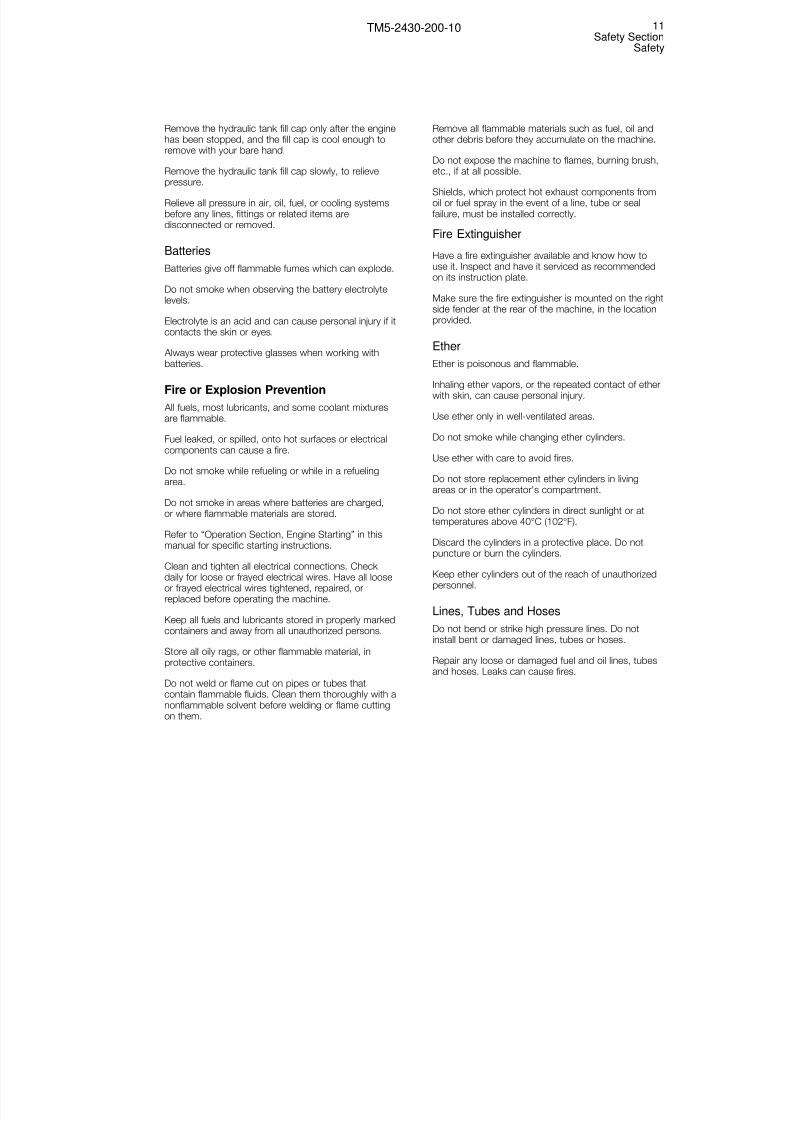
Engine Diagnostic Switch
Move switch (9) up and hold it there for more than twoseconds to activate the engine diagnostic system. Formore information, refer to “Troubleshooting, EngineDiagnostic Codes” in this section.
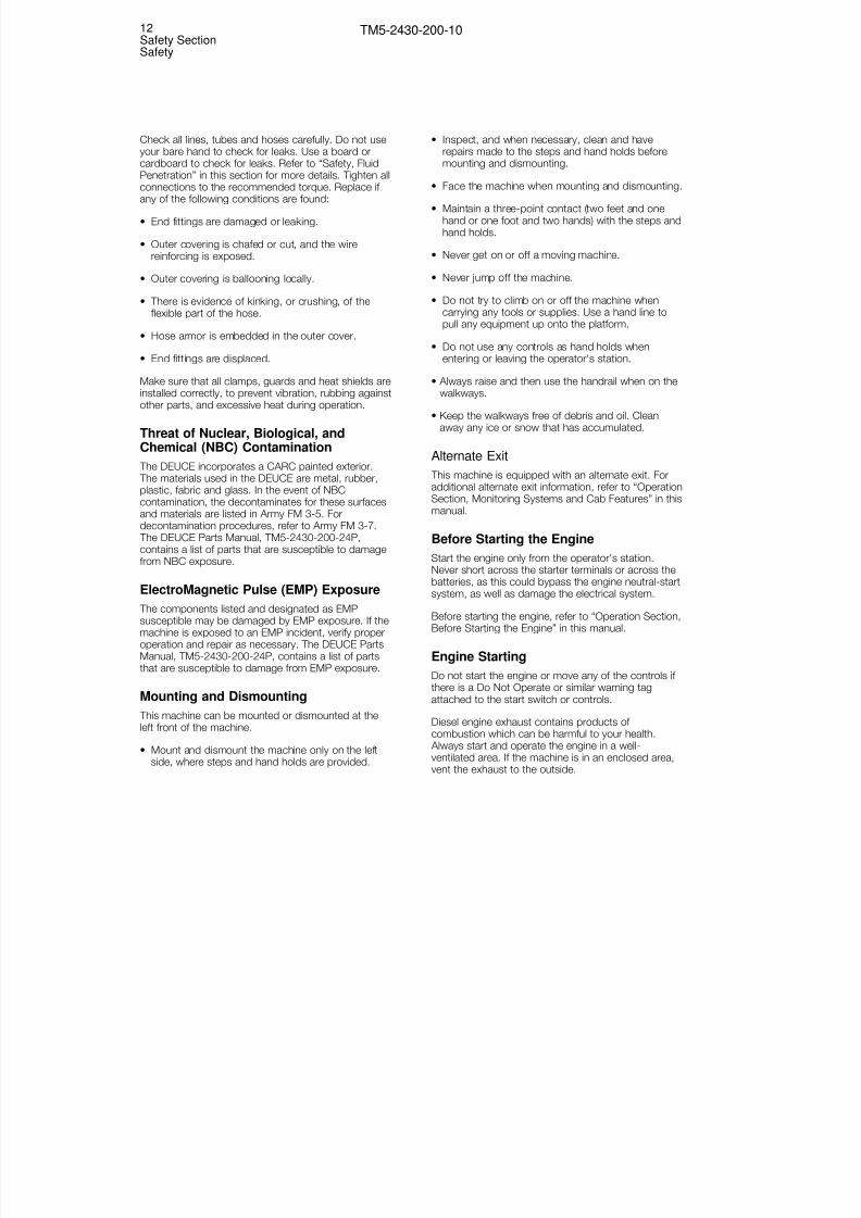
Engine Controller Diagnostic Port
Port (10) is used by maintenance trained personnel todiagnose and calibrate the ECM.
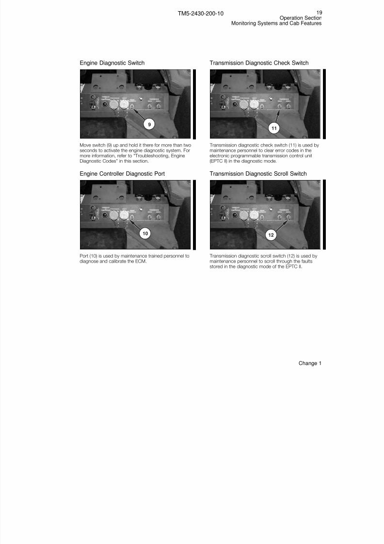
Transmission Diagnostic Check Switch
Transmission diagnostic check switch (11) is used bymaintenance personnel to clear error codes in theelectronic programmable transmission control unit(EPTC II) in the diagnostic mode.
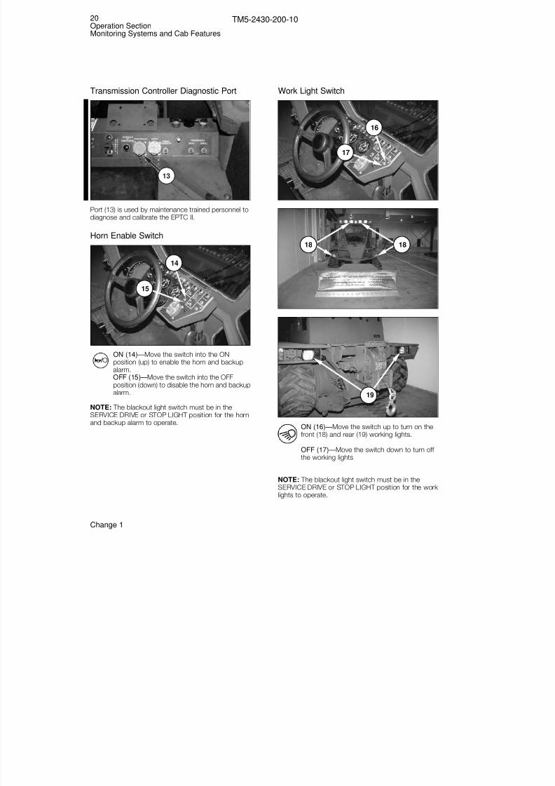
Transmission Diagnostic Scroll Switch
Transmission diagnostic scroll switch (12) is used bymaintenance personnel to scroll through the faultsstored in the diagnostic mode of the EPTC II.
12
11
10
9
19Operation Section
Monitoring Systems and Cab Features
TM5-2430-200-10
Change 1
8/3/2019 TM 5-2430-200-10
http://slidepdf.com/reader/full/tm-5-2430-200-10 26/196
Transmission Controller Diagnostic Port
Port (13) is used by maintenance trained personnel todiagnose and calibrate the EPTC II.
Horn Enable Switch
ON (14)—Move the switch into the ONposition (up) to enable the horn and backupalarm.OFF (15)—Move the switch into the OFFposition (down) to disable the horn and backupalarm.
NOTE: The blackout light switch must be in theSERVICE DRIVE or STOP LIGHT position for the horn
and backup alarm to operate.
Work Light Switch
ON (16)—Move the switch up to turn on thefront (18) and rear (19) working lights.
OFF (17)—Move the switch down to turn off the working lights
NOTE: The blackout light switch must be in theSERVICE DRIVE or STOP LIGHT position for the work lights to operate.
19
18 18
17
16
15
14
13
20Operation SectionMonitoring Systems and Cab Features
TM5-2430-200-10
Change 1

8/3/2019 TM 5-2430-200-10
http://slidepdf.com/reader/full/tm-5-2430-200-10 27/196
Blackout Light Switch
52
5354
42
49
43
50
44
51
45
42
46 47
48
52
37 38
39
40 41
32
33
34
33
34
32
36
35
B.O.DRIVE
B.O.MARKER
STOPLIGHT
SERVICEDRIVE
UNLOCK
PARK
DIM
BRT
PANEL
23
22 24
2521
30
3129
28
27
26
C B
A
OFF
OFF
20
21Operation Section
Monitoring Systems and Cab Features
TM5-2430-200-10
Change 1

8/3/2019 TM 5-2430-200-10
http://slidepdf.com/reader/full/tm-5-2430-200-10 28/196
NOTE: Blackout switch (20) provides overall control of
all lamps on the machine. The position of the threecontrol levers on the blackout switch determineswhich machine lamps are illuminated and theillumination level of all instrument panel lamps.
UNLOCK (30)—Hold lever (B) in the UNLOCK positionto allow lever (A) to move into BLACKOUT DRIVE (21),STOP LIGHT (24), or SERVICE DRIVE (25).
LOCK (31)—When lever (B) is in the LOCK position,movement of lever (A) is restricted.
NOTE: When lever (B) is in the LOCK position (31)and lever (A) is in the OFF position (23), lever (A) can
only be moved into BLACKOUT MARKER (22).However, lever (A) can be moved into OFF (23) fromBLACKOUT DRIVE (21), BLACKOUT MARKER (22),STOP LIGHT (24), or SERVICE DRIVE (25) with lever(B) in the LOCK position.
BLACKOUT DRIVE (21)—Move lever (A) into theBLACKOUT DRIVE position to enable the following
lamps to function:• Blackout Head Lamp (36)• Right and Left Blackout Tail Lamps (41)• Right and Left Blackout Marker Lamps (34)• Right and Left Blackout Brake Lamps (38)• Tension Fail Indicator (49)• Low Brake Pressure Indicator (43)• Blade Down Indicator (50)• Engine Oil Pressure Indicator (44)• Hydraulic Oil Temperature Indicator (54)
BLACKOUT MARKER (22)—Move lever (A) into theBLACKOUT MARKER position to enable the followinglamps to function:
• Right and Left Blackout Tail Lamps (41)• Right and Left Blackout Marker Lamps (34)• Right and Left Blackout Brake Lamps (38)• Tension Fail Indicator (49)
• Low Brake Pressure Indicator (43)• Blade Down Indicator (50)• Engine Oil Pressure Indicator (44)• Hydraulic Oil Temperature Indicator (54)
OFF (23)—Move lever (A) into the OFF position todisable all lights except:
• Tension Fail Indicator (49)• Low Brake Pressure Indicator (43)
• Blade Down Indicator (50)• Engine Oil Pressure Indicator (44)• Hydraulic Oil Temperature Indicator (54)
156
52
55
22Operation SectionMonitoring Systems and Cab Features
TM5-2430-200-10
Change 1

8/3/2019 TM 5-2430-200-10
http://slidepdf.com/reader/full/tm-5-2430-200-10 29/196
STOP LIGHT (24)—Move lever (A) into the STOPLIGHT position to enable the following lamps to
function:• Right and Left Brake Lamps (40)• Interior Light (56)• Right and Left Rear Working Lamps (19)• Right and Left Center Work Lamps (18)• Right and Left Front Work Lamps (18)• Right and Left Turn Lamps (42, on panel)• Rear Right and Left Turn Signal Lamps (37)• Front Right and Left Turn Signal Lamps (33)• Tension Fail Indicator (49)• Low Brake Pressure Indicator (43)• Blade Down Indicator (50)• Engine Oil Pressure Indicator (44)• Hydraulic Oil Temperature Indicator (54)
• Start-Aid Indicator (55)• Check Engine Indicator (51)• Crank-Without-Inject Indicator (45)• Kneeling Mode Indicator (46)• Winch Indicator (47)• Self-Deploy Indicator (48)• Remote Throttle Indicator (53)
NOTE: Lever (A) must be in SERVICE DRIVE position(25) for lever (C) to work.
SERVICE DRIVE (25), OFF (28)—Move lever (A) intothe SERVICE DRIVE position and lever (C) into theOFF position to enable the following lamps to function:
• Right and Left Brake Lamps (40)• Interior Light (56)• Right and Left Rear Working Lamps (19)• Right and Left Center Work Lamps (18)• Right and Left Front Work Lamps (18)• Right and Left Turn Lamps (42, on panel)• Rear Right and Left Turn Signal Lamps (37)• Front Right and Left Turn Signal Lamps (33)• Right and Left Tail Lamps (39)• Right and Left Front Marker Lamps (32)• Right and Left Head Lamps (35)• Tension Fail Indicator (49)• Low Brake Pressure Indicator (43)• Blade Down Indicator (50)
• Engine Oil Pressure Indicator (44)• Hydraulic Oil Temperature Indicator (54)• Start-Aid Indicator (55)• Check Engine Indicator (51)• Crank-Without-Inject Indicator (45)• Kneeling Mode Indicator (46)• Winch Indicator (47)• Self-Deploy Indicator (48)• Remote Throttle Indicator (53)
SERVICE DRIVE (25), PANEL BRIGHT (26)—Movelever (A) into the SERVICE DRIVE position and lever
(C) into the PANEL BRIGHT position to enable thefollowing lamps to function:
• Right and Left Brake Lamps (40)• Interior Light (56)• Right and Left Rear Work Lamps (19)• Right and Left Center Work Lamps (18)• Right and Left Front Work Lamps (18)• Right and Left Turn Lamps (42, on panel)• Rear Right and Left Turn Signal Lamps (37)• Front Right and Left Turn Signal Lamps (33)• Right and Left Tail Lamps (39)• Right and Left Front Marker Lamps (32)• Right and Left Head Lamps (35)• All Panel and Gauge Lamps (52, bright level)
• Tension Fail Indicator (49)• Low Brake Pressure Indicator (43)• Blade Down Indicator (50)• Engine Oil Pressure Indicator (44)• Hydraulic Oil Temperature Indicator (54)• Start-Aid Indicator (55)• Check Engine Indicator (51)• Crank-Without-Inject Indicator (45)• Kneeling Mode Indicator (46)• Winch Indicator (47)• Self-Deploy Indicator (48)• Remote Throttle Indicator (53)
SERVICE DRIVE (25), DIM (27)—Move lever (A) into
the SERVICE DRIVE position and lever (C) into the DIMposition to enable the following lamps to function:
• Right and Left Brake Lamps (40)• Interior Light (56)• Right and Left Rear Work Lamps (19)• Right and Left Center Work Lamps (18)• Right and Left Front Work Lamps (18)• Right and Left Turn Lamps (42, on panel)• Rear Right and Left Turn Signal Lamps (37)• Front Right and Left Turn Signal Lamps (33)• Right and Left Tail Lamps (39)• Right and Left Front Marker Lamps (32)• Right and Left Head Lamps (35)• All Panel and Gauge Lamps (52, dim level)
• Tension Fail Indicator (49)
23Operation Section
Monitoring Systems and Cab Features
TM5-2430-200-10

8/3/2019 TM 5-2430-200-10
http://slidepdf.com/reader/full/tm-5-2430-200-10 30/196
• Low Brake Pressure Indicator (43)• Blade Down Indicator (50)
• Engine Oil Pressure Indicator (44)• Hydraulic Oil Temperature Indicator (54)• Start-Aid Indicator (55)• Check Engine Indicator (51)• Crank-Without-Inject Indicator (45)• Kneeling Mode Indicator (46)• Winch Indicator (47)• Self-Deploy Indicator (48, dim level)• Remote Throttle Indicator (53)
SERVICE DRIVE (25), PARK (29)—Move lever (A)into the SERVICE DRIVE position and lever (C) into thePARK position to enable the following lamps tofunction:
• Right and Left Brake Lamps (40)• Interior Light (56)• Right and Left Rear Working Lamps (19)• Right and Left Center Work Lamps (18)• Right and Left Front Work Lamps (18)• Right and Left Turn Lamps (42, on panel)• Rear Right and Left Turn Signal Lamps (37)• Front Right and Left Turn Signal Lamps (33)• Right and Left Tail Lamps (39)• Right and Left Front Marker Lamps (32)• All Panel and Gauge Lamps (52, dim level)• Tension Fail Indicator (49)• Low Brake Pressure Indicator (43)• Blade Down Indicator (50)
• Engine Oil Pressure Indicator (44)• Hydraulic Oil Temperature Indicator (54)• Start-Aid Indicator (55)• Check Engine Indicator (51)• Crank-Without-Inject Indicator (45)• Kneeling Mode Indicator (46)• Winch Indicator (47)• Self-Deploy Indicator (48, dim level)
Gauges
Engine Oil Pressure (1)—Indicates the engineoil pressure in kPa (psi).
NOTE: The normal engine oil pressure rangeshould be between 250 and 450 kPa (30 and 70 psi)when the engine is running at full speed with SAE15W40 oil at operating temperature.
Engine Coolant Temperature (2)—Indicatesthe temperature of the engine coolant indegrees celsius and degrees fahrenheit. If theengine coolant temperature increases above
110°C (230°F), stop operation of the machine and allowthe engine to idle for a few minutes. If the coolanttemperature will not return to 110°C (230°F) or lessduring normal working conditions, stop the machine
and investigate the cause of engine overheating.
Transmission Oil Temperature (3)—Indicatesthe temperature of the transmission system oilin °C (°F). If the transmission system oiltemperature increases above 110°C (230°F),
stop operation of the machine and allow it to idle for afew minutes. If the transmission oil temperature will notreturn to 110°C (230°F) or less during normal workingconditions, stop the machine and investigate the causeof the transmission system overheating.
Engine RPM (4)—Indicates the engine speed inrevolutions (X100) per minute.
The service hour meter is located on the engine rpmgauge.
Speedometer (5)—Indicates machine ground speed inmiles-per-hour and kilometers-per-hour.
Voltmeter (6)—Indicates the electrical systemvoltage at different operating conditions.
32 4 51
6
7
24Operation SectionMonitoring Systems and Cab Features
TM5-2430-200-10

8/3/2019 TM 5-2430-200-10
http://slidepdf.com/reader/full/tm-5-2430-200-10 31/196
With the start switch in the ON position and theengine NOT RUNNING, a reading in the first red zone
indicates dead batteries.
With the start switch in the ON position and the engineNOT RUNNING, a reading in the black-and-whitestriped zone indicates that the batteries are not fullycharged.
With the start switch in the ON position and theengine NOT RUNNING, a reading in the first greenzone indicates the batteries are fully charged.
With the ENGINE RUNNING, a reading anywherebelow the second green zone (normal operating range)indicates that the alternator is not producing enough
voltage to charge the batteries and supply current tothe electrical accessories.
With the ENGINE RUNNING, a reading in the secondred zone indicates that the alternator is overcharging.
With the ENGINE RUNNING, if the pointer registers inthe first green band, or either red bands, have theproblem corrected.
Fuel Level (7)—Indicates the approximatequantity of fuel in the fuel tank.
NOTICETo prevent the fuel from overheating when themachine is operated in ambient temperatures above38°C (100°F), the fuel level should be maintainedabove one-half of a tank. Overheated fuel can causereduced power and possibly damage the fuel system.
NOTE: The fuel tank capacity is 341 L (90 U.S. gal).
Indicators
The indicators are color coded to indicate theimportance.
• Green— A green indicator means that the indicatedsystem is in operation.
• Orange— An orange indicator means to notice thatan automatically controlled system is operating.
• Red— A red indicator means to pay immediateattention and correct the indicated problemimmediately.
Tension Fail (1)—Indicates low oil pressure in thedrive belt tension system.
Do not operate the machine when the tension faiwarning indicator is lit. Braking efficiency isreduced if there is not enough drive belt tensionPersonal injury or damage to the machine canoccur if there is not enough braking capacity tostop the machine.
Low Brake Pressure (2)—Indicates low oilpressure in the brake system.
Do not operate the machine when the low brakepressure warning indicator is lit. Brakingefficiency is reduced if there is not enough brakesystem pressure. Personal injury or damage to themachine can occur if there is not enough brakingcapacity to stop the machine.
WARNING!
WARNING!
1
2 3
5
6
7
4
25Operation Section
Monitoring Systems and Cab Features
TM5-2430-200-10

8/3/2019 TM 5-2430-200-10
http://slidepdf.com/reader/full/tm-5-2430-200-10 32/196
Blade Down (3)—Indicates that the blade isnot in the full up position when the machine is
in SELF-DEPLOY mode.
NOTE: If the blackout switch is in the STOP LIGHT orSERVICE DRIVE position, the blade down alarm willsound when blade down indicator (3) is illuminated.
Start-Aid (4)—Indicates the operation of thestart-aid system (intake air heater or etherinjection).
NOTE: The blackout switch must be in the STOPLIGHT or SERVICE DRIVE position for start-aidindicator (4) to function.
Engine Oil Pressure (5)—Indicates that thereis not enough engine oil pressure. The oilpressure indicator illuminates when the oil
pressure is 35 ± 21 kPa (5 ± 3 psi)
NOTICEDo not continue to operate the machine if the engineoil pressure indicator is on, or if the engine oil pressuregauge indicates an engine oil pressure of less than 50kPa (10 psi), 15 seconds after starting the engine.Stop the machine immediately and inform UnitMaintenance of the problem. Do not operate themachine until the cause of the low engine oil pressure
has been corrected.
Check Engine (6)—Indicates the presence of a fault code in the engine electronic controlmodule. Refer to “Troubleshooting, Engine
Diagnostic Codes” in this manual for information ondiagnostic codes.
NOTE: The blackout switch must be in the STOPLIGHT or SERVICE DRIVE position for check engineindicator (6) to function.
Crank-Without-Inject (7)—Indicates the fuel deliverysystem has been disabled, to allow the engine to beturned over without starting. This operational mode isused only by service personnel to repair the engine.
NOTE: The blackout switch must be in the STOPLIGHT or SERVICE DRIVE position for crank-without-inject indicator (7) to function.
Turn Signal (8)—Indicates the direction of the turnsignal.
NOTE: The blackout switch must be in the STOPLIGHT or SERVICE DRIVE position for turn signalindicators (8) to function.
Kneeling (9)—Indicates that the machine is fullylowered into the kneeling mode.
NOTE: The blackout switch must be in the STOPLIGHT or SERVICE DRIVE position for kneeling modeindicator (9) to function.
Winch (10)—Indicates that the winch controlsystem is activated.
NOTE: The blackout switch must be in the STOPLIGHT or SERVICE DRIVE position for winch indicator(10) to function.
Self-Deploy Mode (11)—Indicates that the suspensionis active and the machine is in SELF-DEPLOY mode.
NOTE: The blackout switch must be in the STOPLIGHT or SERVICE DRIVE position for self-deploy modeindicator (11) to function.
8
9
10
11
26Operation SectionMonitoring Systems and Cab Features
TM5-2430-200-10

8/3/2019 TM 5-2430-200-10
http://slidepdf.com/reader/full/tm-5-2430-200-10 33/196
Remote Throttle (12)—Indicates that the enginespeed is being controlled by the remote throttle
switch.
NOTE: The blackout switch must be in the STOPLIGHT or SERVICE DRIVE position for remote throttleindicator (12) to function.
Hydraulic Oil Temperature (13)—Indicates that thehydraulic oil temperature is too high. If this light comeson during operation, slow the machine until the lightgoes off. If the light continues to illuminate duringnormal operating conditions, have the cause of thehydraulic system overheating investigated andcorrected.
NOTE: The blackout switch must be in the STOPLIGHT or SERVICE DRIVE position for hydraulic oiltemperature indicator (13) to function.
Recoil Alert
Recoil Indicator LH (1) and/or Recoil Indicator RH (2)will illuminate, and a warning buzzer (3) will soundwhen the machine encounters an obstruction in theundercarriage and the recoil cylinder is compressed. If the recoil alert sounds, stop the machine and reversedirection to clear debris from the undercarriage.
NOTICEDuring earthmoving operations it is possible tocollapse the recoil cylinder completely. To reduce thepossibility of breaking track belts in this condition arecoil alarm has been added to the machine to alertthe operator that a hazardous condition exists.
NOTE: The position of the blackout switch does noteffect the recoil alert warning lights.
Indicator Check Function
When the engine is running, the start position of the
engine start switch (1) will perform an indicator check function.
NOTE: The ECM will disengage the starter at 600rpm. Holding the starter engaged after the engine hasstarted will not damage the starter.
When engine start switch (1) is held in the START position, the following indicators will turn on to test forfailed indicator bulbs. Have Unit Maintenancepersonnel replace any indicator bulbs that do not turnon during the check.
NOTE: The blackout light switch must be in the STOPLIGHT or SERVICE DRIVE position for the indicators toturn on in the indicator check function.
1
12 1312 13
27Operation Section
Monitoring Systems and Cab Features
TM5-2430-200-10
Change 1
3
1 21
3
2

8/3/2019 TM 5-2430-200-10
http://slidepdf.com/reader/full/tm-5-2430-200-10 34/196
(2) Tension Fail.
(3) Low Brake Pressure.
(4) Blade Down.
(5) Engine Oil Pressure.
(6) Kneeling.
(7) Winch
(8) Self-Deploy Mode.
(9) Remote Throttle.
(10) Hydraulic Oil Temperature.
Steering Column
Horn (1)—Press the center button in the steeringwheel to sound the horn.
NOTE: The horn switch must be ON, and the blackoutswitch must be in the STOP LIGHT or SERVICE DRIVEposition for horn (1) to function.
Turn Signal (2)—Move lever (2) forward to activate theright turn signal. Move lever (2) rearward to activatethe left turn signal.
NOTE: The blackout switch must be in the STOPLIGHT or SERVICE DRIVE position for turn signal (2) tofunction.
Wiper/Washer (2)— Turn the knob on the end of lever(2) to turn on the wiper. There are two positionscorresponding to two wiper speeds. Press the knob into activate the washer.
Tilt (3)—Lift and hold lever (3) to tilt the steeringcolumn. Release the lever when the steering column isin the desired position.
5
2
3
4
1
9 109 10
8
2
34 5 6
7
28Operation SectionMonitoring Systems and Cab Features
TM5-2430-200-10
Change 1

8/3/2019 TM 5-2430-200-10
http://slidepdf.com/reader/full/tm-5-2430-200-10 35/196
Extend and Retract (4)—Slide the lever to the right toextend or retract the steering column. Slide the lever
to the left to lock the steering column in the desiredlocation.
Hazard Warning Lights (5)—Push centerbutton (5) in to turn on the flashers. Pull theouter collar out to turn off the flashers.
NOTE: The blackout switch must be in the STOPLIGHT or SERVICE DRIVE position for hazard warninglights switch (5) to function.
Cooling Fan
There are two cooling fans mounted in the cab. Onefan is mounted in the left rear corner of the cab. Theother fan is mounted in the right front corner of thecab.
Off—Move switch (1) to the center position to turn thefan off.
High—Move switch (1) to the left to operate the fan athigh speed.
Low—Move switch (1) to the right to operate the fanat low speed.
1
29Operation Section
Monitoring Systems and Cab Features
TM5-2430-200-10

8/3/2019 TM 5-2430-200-10
http://slidepdf.com/reader/full/tm-5-2430-200-10 36/196
Arm Rest
Loosen bolts (2). Move arm rest (1) up or down to thedesired position, and tighten the bolts.
Interior Light
ON—Push the bottom of switch (1) in to turn ON theinterior light.
OFF—Push the top of switch (1) in to turn OFF theinterior light.
NOTE: The blackout switch must be in the STOPLIGHT or SERVICE DRIVE position for the interior lampto function.
1
2
1
30Operation SectionMonitoring Systems and Cab Features
TM5-2430-200-10

8/3/2019 TM 5-2430-200-10
http://slidepdf.com/reader/full/tm-5-2430-200-10 37/196
Cab Door
Open From Outside
Pull handle (1) up to release the latch and open thedoor.
Secure In Hold-Open Position
Press door (2) firmly against the side wall of the cab toengage the latch and secure the door in the openposition.
Release From Hold-Open Position
Move lever (3) towards the front of the machine torelease the door from the hold-open position.
Open From Inside
Push lever (4) towards the front of the machine torelease the door from the inside.
4
3
2
1
31Operation Section
Monitoring Systems and Cab Features
TM5-2430-200-10

8/3/2019 TM 5-2430-200-10
http://slidepdf.com/reader/full/tm-5-2430-200-10 38/196
Side Window
Squeeze levers (1 and 2) on both sides of the windowto raise or lower the window. Release the levers whenthe window is in the desired position.
Alternate Exit
Push lever (1) up and toward the window to releasethe latch. Swing the window towards the front of themachine to open, and exit through the window frame.
Air Conditioning/Heating Controls
Air Conditioning Turn switch (2) counterclockwise (left) to activate theair conditioner. There are three positions whichcorrespond to three speeds for the blower fan.
Turn knob (1) clockwise (right) for cooler air.
Heating
Turn switch (2) clockwise (right) to activate the heater. There are three positions which correspond to threespeeds for the blower fan.
Turn knob (1) counterclockwise (left) for warmer air.
1 21 2
1
1
2
32Operation SectionMonitoring Systems and Cab Features
TM5-2430-200-10
Change 1
8/3/2019 TM 5-2430-200-10
http://slidepdf.com/reader/full/tm-5-2430-200-10 39/196
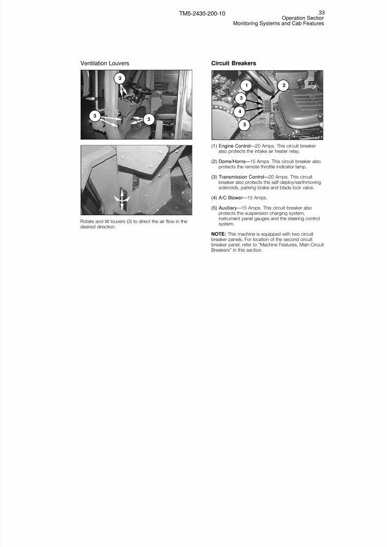
Ventilation Louvers
Rotate and tilt louvers (3) to direct the air flow in thedesired direction.
Circuit Breakers
(1) Engine Control—20 Amps. This circuit breakeralso protects the intake air heater relay.
(2) Dome/Horns—15 Amps. This circuit breaker alsoprotects the remote throttle indicator lamp.
(3) Transmission Control—20 Amps. This circuitbreaker also protects the self-deploy/earthmovingsolenoids, parking brake and blade lock valve.
(4) A/C Blower—15 Amps.
(5) Auxiliary—15 Amps. This circuit breaker alsoprotects the suspension charging system,instrument panel gauges and the steering controlsystem.
NOTE: This machine is equipped with two circuitbreaker panels. For location of the second circuitbreaker panel, refer to “Machine Features, Main CircuitBreakers” in this section.
1
3
5
4
2
3
3
3
33Operation Section
Monitoring Systems and Cab Features
TM5-2430-200-10

8/3/2019 TM 5-2430-200-10
http://slidepdf.com/reader/full/tm-5-2430-200-10 40/196
Seat Belt
Always check the condition of the seat belt and itsmounting hardware before operating the machine.
Replace the seat belt at least once every three years,regardless of its appearance. Date label (1) indicatesthe belt fabrication date. Replace the belt if the dateon the label is older than three years.
Inspect for worn or frayed webbing.
Check for a worn or damaged buckle. Replace thebelt, buckle or slide if they are worn or damaged.
Inspect the belt mounting hardware at locations (2).Have Unit Maintenance replace any damaged or wornhardware. Keep the mounting bolts tight.
Seat Belt Adjustment
The seat belt is equipped with an automatic lockingretractor. This retractor will lock if the belt is pulled or jerked after the belt is pulled out of the retractor.
The buckle end of the seat belt is equipped with acomfort ride sleeve. This sleeve will allow the operatorlimited movement with the seat belt fastened.
Pull seat belt (1) out of the retractor in a continuousmotion.
Fasten seat belt catch (2) into buckle (3). Check tomake sure the seat belt is placed low across the lap.
The retractor will adjust the belt length and lock inplace. The operator has limited movement whilewearing the seat belt.
To Release the Seat Belt
Push the release button on the buckle to release theseat belt. The seat belt will automatically retract intothe retractor.
1
32
2
1
34Operation SectionMonitoring Systems and Cab Features
TM5-2430-200-10

8/3/2019 TM 5-2430-200-10
http://slidepdf.com/reader/full/tm-5-2430-200-10 41/196
Seat Adjustment
Raise/Lower (1)—Lift and hold the lever up, raise orlower the seat, and then release the lever to lock theseat at the desired height.
Suspension (2)— Turn the knob clockwise to increasethe stiffness of the suspension. Turn the knobcounterclockwise to decrease the stiffness of thesuspension. When the desired stiffness is achieved, ayellow indicator will be flush with the end of a smalltube at the lower left front of the seat frame.
Fore/Aft (3)—Move and hold the lever out (away fromthe seat cushion), and slide the seat fore or aft. Releasethe lever when the seat is in the desired position.
Mirrors
Move mirror (1) by hand to set the correct angle formaximum visibility. The machine is equipped with amirror on both sides of the cab. Fold the mirrorsagainst the side of the cab when operating in areaswhere the mirrors can be damaged by branches orother objects.
Rear View Mirror
Loosen knob (2) and rotate mirror (1) up or down. Tighten the knob when the mirror is in the desiredlocation.
PLGR Bracket
Mounting bracket (1) for the Precision LightweightGPS Receiver (PLGR) is located on the controlconsole to the right of the operator.
NOTE: Refer to Appendix F for PLGR installationinstructions.
1
1
2
1
1
2
3
35Operation Section
Monitoring Systems and Cab Features
TM5-2430-200-10
Change 1

8/3/2019 TM 5-2430-200-10
http://slidepdf.com/reader/full/tm-5-2430-200-10 42/196
SINCGARS Bracket Installation
Single Channel Ground and Airborne Radio System(SINCGARS) mounting bracket installation location (1)is to the left of the operator’s seat, on the cab floor.
NOTE: For instructions to install the SINCGARS, unitmaintenance should refer to TB11-5820-890-20-113,Installation Instructions for Installation Kit, ElectronicEquipment, MK-2901/VRC (NSN 5895-01-458-1547)(EIC: N/A) to Permit Installation of Radio Sets AN/VRC-87/88/89 Series in a DEUCE Vehicle. Thispublication should be read and understood before theSINCGARS is installed.
PLGR/SINCGARS Power Strip
Power strip (1) for the PLGR and SINCGARS islocated behind and to the left of the operator’s seat.
NOTE: The capacity of the power strip is 10 amps at24 volts. The power strip is protected by the startcircuit breaker. Refer to “Operation Section, MachineFeatures, Main Circuit Breakers” in this manual for thelocation of this circuit breaker.
Rifle Bracket
Rifle bracket (1) is located in front of the right console,on the right side of the cab.
Windshield Washer Fluid Bottle
Windshield washer fluid bottle (1) is located on theright side wall of the cab.
1
1
1
1
36Operation SectionMonitoring Systems and Cab Features
TM5-2430-200-10

8/3/2019 TM 5-2430-200-10
http://slidepdf.com/reader/full/tm-5-2430-200-10 43/196
Coat Hook
Coat hook (1) is located in the right rear corner of thecab.
Rear Windshield Guard
To raise rear windshield guard (1), pull out sharply onthe lower corners to release the guard from the rubberfasteners. Raise the guard and allow it to rest on thetop of the cab.
To lower rear windshield guard (1), raise the guard off the top of the cab and rotate it down in position overthe rear window. Press sharply on the lower corners othe guard to secure it in rubber fasteners (2).
NOTE: Rear windshield guard (1) provides protectionfor the operator when the winch is operated. The rearwindshield guard should only be raised to clean orreplace the rear windshield. At all other times, the rear
windshield guard should be lowered and secured inrubber fasteners (2).
Operation of the winch while rear windshield guard(1) is in the raised position could result in injury ordeath.
WARNING!
1
2
1
1
37Operation Section
Monitoring Systems and Cab Features
TM5-2430-200-10

8/3/2019 TM 5-2430-200-10
http://slidepdf.com/reader/full/tm-5-2430-200-10 44/196
Parking Brake
NOTICEDo not apply the parking brake while the machine ismoving, unless an emergency exists.
With the engine running, this machine will spotturn when the steering wheel is turned, even if thetransmission is in NEUTRAL.
To avoid personal injury due to unexpectedmovement, engage the parking brake and make
sure the area is free of personnel before startingthe engine.
Parking brake switch (1) is located on thecontrol console, to the right of the operator’sseat.
Pull up on the switch to apply the parking brake.
NOTE: A lamp inside parking brake switch (1) willindicate that the brake is applied.
Push down on the switch to release the parking brake.
NOTE: The parking brake must be applied for theengine starter to function.
Service Brakes
Depressing pedal (1) applies equal braking torque toboth front idlers. Increasing pedal stroke increasesbrake torque.
This machine is equipped with an accumulator inthe brake system. The accumulator stores energy toapply the brakes if the engine stops running. Thebrake accumulator stores enough energy to apply
the brakes five times after the engine stops. Whenthe accumulator pressure is gone, the spring-applied parking brake will engage, and the machinewill stop suddenly.
NOTICEUse caution when towing loads at transport speeds(up to 15 mph). Reduce speed if towed load is notequipped with brakes. Avoid hard braking applications.
NOTE: Never rest a foot on the pedal. Resting a footon the brake pedal causes unnecessary wear of the
brake disks.
WARNING!
1
1
WARNING!
38Operation SectionMachine Features
TM5-2430-200-10
Machine Features
Change 1

8/3/2019 TM 5-2430-200-10
http://slidepdf.com/reader/full/tm-5-2430-200-10 45/196
Accelerator Pedal
Push pedal (1) down to increase the engine speed.Release the pedal to decrease the engine speed.
Steering Wheel
Turn wheel (1) to the right to steer the machine to theright. Turn the wheel to the left to steer the machineleft.
Transmission Control Lever
NEUTRAL (1)—Move the lever into the detentposition marked “N” to put the transmissioninto NEUTRAL.
Forward (2)—Move the lever forward to select one of six forward transmission speeds, marked “1” through“6.”
When the machine is in EARTHMOVING mode, thetransmission is limited to three forward speeds. Eachspeed is manually selected. If the transmission controllever is placed in any position above “3,” thetransmission will remain in third gear.
When the machine is in SELF-DEPLOY mode, thereare six forward speeds. The transmission willautomatically shift between first gear and themaximum gear selected.
Reverse (3)—Move the lever to the rear toplace the transmission into one of two reversespeeds, marked “R1” and “R2.”
1
3
2
1
1
39Operation SectionMachine Features
TM5-2430-200-10

8/3/2019 TM 5-2430-200-10
http://slidepdf.com/reader/full/tm-5-2430-200-10 46/196
Main Disconnect Switch
Second Main Disconnect Switch for Optional Arctic StartingSystem.
The main disconnect switch is located in electricalpanel and BII compartment (1) at the rear of themachine. A second disconnect switch is located onthe arctic battery box on the left fender, if the machineis equipped with the optional arctic starting system.
NOTE: If the machine is equipped with the optionalarctic starting system, both disconnect switches mustbe in the OFF position to disable the electrical system.
ON (2)— Turn the switch ON to connect theelectrical system to ground.
OFF (3)— Turn the switch OFF to disconnectthe electrical system from ground.
NOTICENever turn the main disconnect switches to OFF withthe engine running. Electrical system damage couldresult.
2 3
2 3
1
40Operation SectionMachine Features
TM5-2430-200-10
Change 1

8/3/2019 TM 5-2430-200-10
http://slidepdf.com/reader/full/tm-5-2430-200-10 47/196
Main Circuit Breakers
Press the red button to reset the circuit breaker.
(1) Main—105 Amps
(2) ALT (Alternator)—105 Amps
(3) AIH (Intake Air Heater)—80 Amps
(4) (Engine Coolant Heater)—30 Amps
(5) Ether—15 Amps
(6) Start—10 Amps
NOTE: The main circuit breaker panel is one of twocircuit breaker panels on this machine. For thelocation of the other circuit breaker panel, refer to“Monitoring Systems and Cab Features, CircuitBreakers” in this section.
Auxiliary Start Receptacle (NATO Slave)
Auxiliary start receptacle (NATO slave) (1) is located atthe left rear of the machine.
If the machine is equipped with the optional arcticstarting system, auxiliary start receptacle (NATO slave)(1) is located on the arctic battery box on the leftfender.
1
1
5
3
1
2
4
6
41Operation SectionMachine Features
TM5-2430-200-10
Change 1
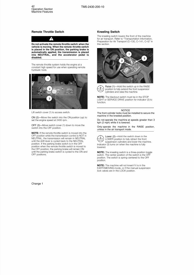
8/3/2019 TM 5-2430-200-10
http://slidepdf.com/reader/full/tm-5-2430-200-10 48/196
Remote Throttle Switch
Do not activate the remote throttle switch when thevehicle is moving. When the remote throttle switchis placed in the ON position, the parking brake isautomatically applied, the transmission is placedinto NEUTRAL, and the accelerator pedal isdisabled.
The remote throttle system holds the engine at aconstant high speed for use when operating remotehydraulic tools.
Lift switch cover (1) to access switch.
ON (2)—Move the switch into the ON position (up) toset the engine speed at 2400 rpm.
OFF (3)—Move switch cover (1) down to move theswitch into the OFF position.
NOTE: If the remote throttle switch is moved into theOFF position while the transmission control is NOT inNEUTRAL, the transmission will remain in NEUTRALuntil the shift lever is cycled back to the NEUTRALposition. If the parking brake switch is in the OFFposition when the remote throttle switch is moved to
the OFF position, the parking brake will remain ONuntil the parking brake switch is cycled to the ON andOFF positions.
Kneeling Switch
The kneeling switch lowers the front of the machinefor air transport. Refer to “Transportation Information,Preparation for Air Transport (C–130, C–141, C–5)” inthis section.
Raise (1)—Hold the switch up in the RAISEposition to fully extend the front suspensioncylinders and raise the machine.
NOTE: The blackout switch must be in the STOPLIGHT or SERVICE DRIVE position for indicator (3) tofunction.
NOTICEThe front cylinder locks must be installed to secure themachine in the kneeled position.
Do not operate the machine at speeds greater than 3kph (2 mph) while it is lowered.
Only operate the machine in the RAISE position,unless in the air transport mode.
Lower (2)—Hold the switch down in theLOWER position to fully retract the frontsuspension cylinders and lower the machine.
Indicator (3) turns on when the machine is fullylowered.
NOTE: The kneeling switch is a three-position toggleswitch. The center position of the switch is the OFFposition. The switch is spring-centered to the OFFposition.
NOTE: The machine will not kneel if it is in theEARTHMOVING mode, or if the manual suspensionlock valves are in the LOCK position.
3
1
2
3
2
1
42Operation SectionMachine Features
TM5-2430-200-10
Change 1
WARNING!

8/3/2019 TM 5-2430-200-10
http://slidepdf.com/reader/full/tm-5-2430-200-10 49/196
Self-Deploy/Earthmoving Mode Switch
SELF-DEPLOY (1)—Move the switch into the SELF-DEPLOY position (up) to put the machine into SELF-DEPLOY mode.
Indicator (3) turns on when the machine hassuccessfully been put into SELF-DEPLOY mode, if theblackout switch is in the SERVICE DRIVE or STOPLIGHT position.
When the machine is in SELF-DEPLOY mode, thesuspension is active to protect the machine fromshock loads while travelling at high speed; the bladewill operate in all directions except LOWER; and theengine operates at the high horsepower setting.
NOTE: Refer to “Machine Operation, Self-DeployMode” in this section for the procedure to put themachine into SELF-DEPLOY mode.
NOTICEDo not operate on slopes greater than 30 percent (17°)with the machine in SELF-DEPLOY mode. Use onlyEARTHMOVING mode for slopes greater than 30percent (17°).
EARTHMOVING (2) – Move the switch into theEARTHMOVING position (down) to put the machine
into EARTHMOVING mode.
When the machine is in EARTHMOVING mode, thesuspension is deactivated to stabilize the machine forprecision blade control, and the engine operates atthe low horsepower setting.
NOTE: Refer to “Machine Operation, EarthmovingMode” in this section for the procedure to put themachine into EARTHMOVING mode.
Winch Control Switches
Winch Enable Switch
Lift switch cover (1) to access the switch.
ON (2)—Move the switch into the ON position(up) to enable the winch control system.
OFF (3)—Move the switch into the OFFposition (down) by closing cover (1), to disablethe winch control system.
Indicator (7) turns on when the winch is enabled if theblackout switch is in the SERVICE DRIVE or STOPLIGHT position.
Winch Control Switch
This switch is active when the winch enable switch isin the ON position. The winch clutch must be in theENGAGED position for the winch to operate (refer to“Operation Section, Equipment Controls, WinchControls” in this manual).
IN (4)—Hold the switch in the IN position (up)to operate the winch to reel in the cable.
HOLD (5)—Leave the switch in the center position tostop the winch.
OUT (6)—Hold the switch in the OUT position(down) to operate the winch to reel out thecable.
Refer to “Winch Operation,” in this manual, for moreinformation on winch functions.
17
2
3
6
5
4
3
1
2
43Operation SectionMachine Features
TM5-2430-200-10

8/3/2019 TM 5-2430-200-10
http://slidepdf.com/reader/full/tm-5-2430-200-10 50/196
Kneeling Lock Pin
The kneeling lock pin locks the kneeling cylinder inplace to ensure that the machine does not drift upafter it has been put into the kneeled position. There isa pin on the kneeling cylinder, on each side of themachine.
To lock the kneeling cylinders, remove the pin frombracket (1) on both sides of the machine. When themachine is fully kneeled, insert the pin through bracket(1) and locking bar (2), on both sides of the machine.
NOTE: Use the pump lever to install and remove thepins. The pump lever and kneeling lock pins arenormally stored in the BII compartment at the rear of
the machine.
NOTICEThe kneeling lock pins should be installed only duringair transport. Operating the machine with the kneelinglock pins installed may damage the machine.
Remote Hydraulic Tool Ports
Valve (1) controls the pressure setting in the hydraulicsystem when the remote hydraulic tools are in use. This valve should be closed (turned clockwise againstthe stop) during normal machine operation.
NOTICEThe engine may not start if valve (1) is open. Machineperformance is adversely effected when the valve isopen during normal machine operation.
Ports (2) and (3) supply hydraulic oil to remotehydraulic tools. The ports are located in the air filtercompartment, on the left side of the machine.
NOTE: Refer to the operation manual of the hydraulictool being used for any cautions, notices, or warningsregarding the operation and use of remote tools.
NOTE: Refer to “Machine Operation, RemoteHydraulic Power Manifold” in this section for theprocedure to operate the remote hydraulic toolfunction.
NOTE: Ports (4) and (5) are used for raising the bladeand releasing the park brake.
1 2
3
5
41
2
44Operation SectionMachine Features
TM5-2430-200-10

8/3/2019 TM 5-2430-200-10
http://slidepdf.com/reader/full/tm-5-2430-200-10 51/196
Cab/Radiator Tilt Controls
The cab/radiator tilt controls are used by UnitMaintenance personnel for repairing the machine.
Selector Knobs (1)—When the selector knobs arepointing upwards (turned fully clockwise) the radiatortilt circuit is active. When the selector knobs arepointing downward (turned fully counterclockwise) thecab tilt circuit is active.
Pump Bracket (2)— The pump bracket is used with alever to raise and lower the cab or radiator.
Direction Selector (3)— The slotted end of the pumplever is used to turn the direction selector. When thedirection selector is turned fully counterclockwise,pumping the lever will lower the cab/radiator. Whenthe direction selector is turned fully clockwise,pumping the lever will raise the cab/radiator.
Emergency Drive Belt TensionAdjustment Controls
Radiator Shown in Raised Position for Photographic Clarity.
Auxiliary Charge Switch (1) – Move and hold theauxiliary charge switch up to pressurize the drive belttension adjustment circuit.
Port (2) – The port provides pressurized hydraulic oilto increase the tension of the drive belt.
NOTE: Port (2) can be accessed by raising theradiator (as shown), or through the air filtercompartment. For the belt tension procedures, refer to“Machine Operation, Emergency Belt Tension
Procedure” in this section.
2
1 2
3
5
4
1
3
2
45Operation SectionMachine Features
TM5-2430-200-10

8/3/2019 TM 5-2430-200-10
http://slidepdf.com/reader/full/tm-5-2430-200-10 52/196
Suspension Manual Lockout Valves
Suspension manual lockout valves (1) are located onboth sides of the main frame, in front of the drivewheels. Turn both valves counterclockwise tomanually lock the suspension. Turn both valvesclockwise to control the suspension using the self-deploy/earthmoving mode switch in the cab.
NOTICEDo not operate the machine in SELF-DEPLOY modewhen the suspension is locked by the manualsuspension lockout valves. Damage to the machinemay result.
Do not air drop the machine with the manual
suspension lockout valves in the LOCK position.Damage to the machine may occur.
Fire Extinguisher Bracket
Fire extinguisher bracket (1) is located on the rightfender at the rear of the machine.
Decontamination Container Bracket
Decontamination container bracket (1) is located onthe right side of the machine.
Pintle Hook
Pintle hook (1) is located at the rear of the machine.
1
1
1
1
46Operation SectionMachine Features
TM5-2430-200-10
Change 1
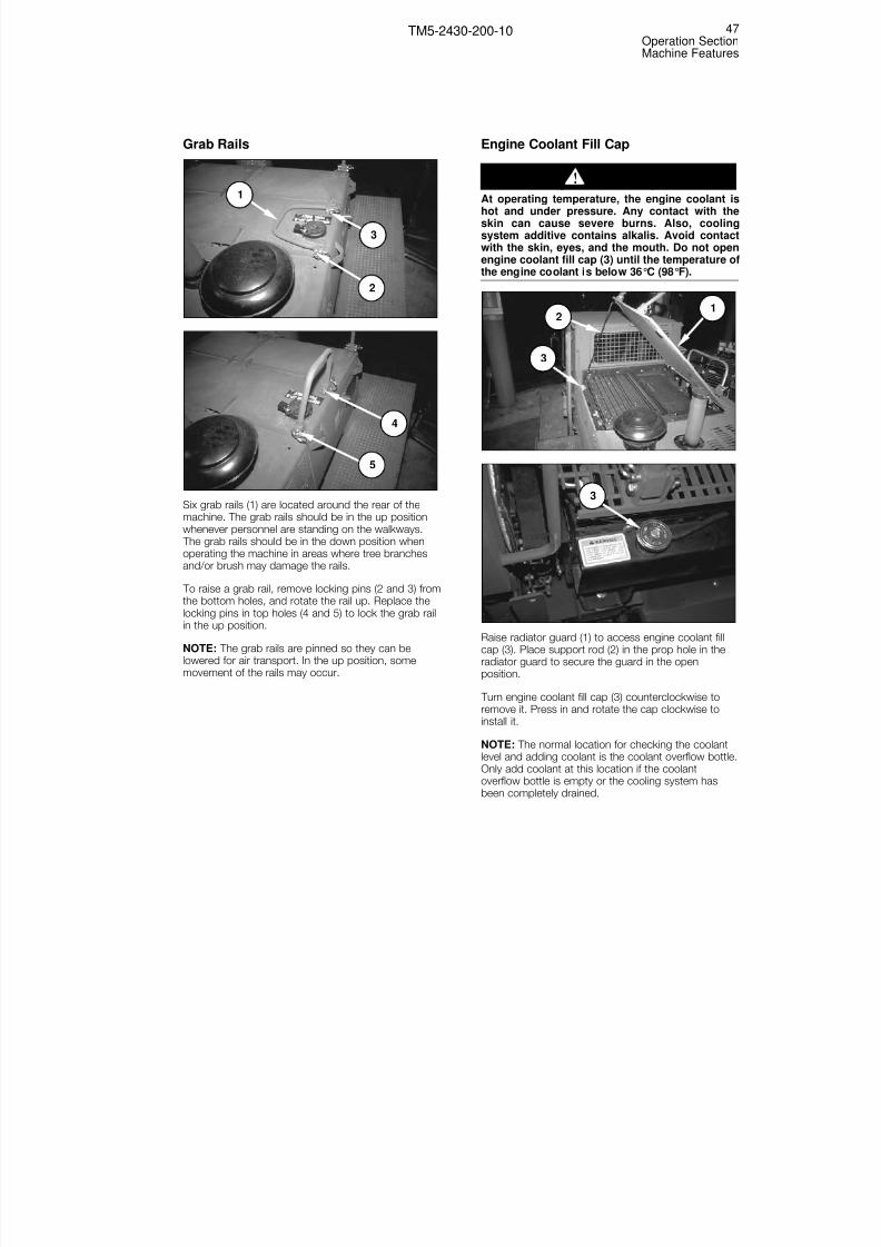
8/3/2019 TM 5-2430-200-10
http://slidepdf.com/reader/full/tm-5-2430-200-10 53/196
Grab Rails
Six grab rails (1) are located around the rear of themachine. The grab rails should be in the up positionwhenever personnel are standing on the walkways. The grab rails should be in the down position whenoperating the machine in areas where tree branchesand/or brush may damage the rails.
To raise a grab rail, remove locking pins (2 and 3) fromthe bottom holes, and rotate the rail up. Replace thelocking pins in top holes (4 and 5) to lock the grab railin the up position.
NOTE: The grab rails are pinned so they can belowered for air transport. In the up position, some
movement of the rails may occur.
Engine Coolant Fill Cap
At operating temperature, the engine coolant ishot and under pressure. Any contact with theskin can cause severe burns. Also, coolingsystem additive contains alkalis. Avoid contactwith the skin, eyes, and the mouth. Do not openengine coolant fill cap (3) until the temperature othe engine coolant is below 36°C (98°F).
Raise radiator guard (1) to access engine coolant fillcap (3). Place support rod (2) in the prop hole in theradiator guard to secure the guard in the open
position.
Turn engine coolant fill cap (3) counterclockwise toremove it. Press in and rotate the cap clockwise toinstall it.
NOTE: The normal location for checking the coolantlevel and adding coolant is the coolant overflow bottle.Only add coolant at this location if the coolantoverflow bottle is empty or the cooling system hasbeen completely drained.
3
2
3
1
WARNING!
5
4
1
2
3
47Operation SectionMachine Features
TM5-2430-200-10

8/3/2019 TM 5-2430-200-10
http://slidepdf.com/reader/full/tm-5-2430-200-10 54/196
Fuel Tank Fill Cap
To remove fuel cap (1), raise lever (2) and turn thelever counterclockwise. To install fuel cap (1), installthe cap, turn lever (2) clockwise and lower the lever.
Hydraulic Oil Tank Fill Cap
Remove— To remove the hydraulic oil tank fill cap, liftand hold lever (1) while rotating cap (2)counterclockwise.
Install— To install the hydraulic oil tank fill cap, lift andhold lever (1) while rotating cap (2) clockwise.
Power Train Oil Fill Cap
The power train oil fill cap is located under rearwalkway (2). Raise the rear walkway and secure thewalkway in the up position by inserting the plungerson the walkway into cups (1).
Remove— To remove the power train oil fill cap, rotatecap (3) counterclockwise.
Install— To install the power train oil fill cap, rotate cap(3) clockwise.
Secure rear walkway (1) in the down position bylowering the walkway until plunger (4) inserts in cup(5).
NOTE. Rear walkway (1) is equipped with one plunger(4) and cup (5) on each side.
3
4
5
21
1 2
12
48Operation SectionMachine Features
TM5-2430-200-10

8/3/2019 TM 5-2430-200-10
http://slidepdf.com/reader/full/tm-5-2430-200-10 55/196
Electrical Panel and BII Compartmentand Tool and Battery Compartment
Electrical panel and BII compartment (1) is the leftcompartment at the rear of the machine. To gainaccess to the electrical panel and BII compartment, liftthe bottom of rubber latches (4), and then rotate thetop of the rubber latches away from the compartment.Use grab rail (3) to pull the lid towards the rear of themachine, and then raise the lid.
Close electrical panel and BII compartment (1) bylowering the lid, rotating the top of rubber latches (4)towards the compartment, and then pushing thebottom of the rubber latches towards thecompartment. The lid is secure when the top of the
rubber latch clamps the lip which is attached to thelid.
Tool and battery compartment (2) is the rightcompartment, at the rear of the machine. Two rubberlatches (5) secure the lid of the compartment. Accessto the tool battery compartment can be gained byfollowing the same procedure as described for accessto electrical panel and BII compartment (1).
Emergency Brake Release Valve
NOTE: The emergency brake release valve is used byUnit Maintenance personnel when they tow themachine.
Radiator Shown in Raised Position for Photographic Clarity.
Valve (1) is located on the multifunction valve in the airintake compartment, on the left side of the machine.
Open— Turn valve (1) fully counterclockwise for normaoperation.
Closed— Turn valve (1) fully clockwise to prepare themachine for manual parking brake release. When valve(1) is closed, the drain passage from the parking brake
is plugged, which allows the manual brake releasepump to operate.
1
1 2
3
45
49Operation SectionMachine Features
TM5-2430-200-10

8/3/2019 TM 5-2430-200-10
http://slidepdf.com/reader/full/tm-5-2430-200-10 56/196
Blade Controls
Blade control lever (1) is located on the controlconsole, to the right of the operator.
Float (2)—Push the lever all the way forwardinto the detent position. The blade moves up
and down, following the contour of theground.
Angle Left (3)—Rotate the blade control levercounterclockwise to angle the blade to the left. The lever returns to HOLD when released.
Lower (4)—Move the blade control leverforward to lower the blade. The lever returns toHOLD when released.
Tilt Left (5)—Move the blade control lever tothe left to tilt the left corner of the blade down.
The lever returns to HOLD when released.
Hold (6)—Return the lever to the centerposition to stop the blade from moving in anydirection.
NOTE: The lever is spring-centered to the HOLDposition, when released from all positions exceptFLOAT.
Tilt Right (7)—Move the blade control lever tothe right to tilt the right corner of the bladedown. The lever returns to HOLD whenreleased.
Lift (8)—Move the blade control lever to therear, to lift the blade. The lever returns toHOLD when released.
Angle Right (9)—Rotate the blade controllever clockwise to angle the blade to the right. The lever returns to HOLD when released.
Back Rippers
There are four back rippers (10) mounted on the bladeand the blade C-frame. Use the blade control lever toposition the rippers while ripping.
10
3
4
8
5
2
76
9
1
50Operation SectionEquipment Controls
TM5-2430-200-10
Equipment Controls
Change 1

8/3/2019 TM 5-2430-200-10
http://slidepdf.com/reader/full/tm-5-2430-200-10 57/196
Winch Controls
Winch Clutch
Do not move the winch clutch lever to theDISENGAGED position with a load on the line. Theload is released uncontrolled and can result inpersonal injury or death.
Disengaged (1)— To disengage the winch, pull knob(3) on the clutch lever out, and rotate the lever to theDISENGAGED position. Release the knob so the peginserts in the hole in the winch frame.
Engaged (2)— To engage the winch, pull knob (3) onthe clutch lever out, and rotate the lever to theENGAGED position. Release the knob so the peginserts in the hole in the winch frame.
NOTE: It may be necessary to momentarily operatethe winch in or out to allow the winch clutch toengage smoothly.
NOTICEDo not force the winch clutch lever into position.Damage to the winch may result if the lever is forced.
WARNING!
1
2
3
51Operation Section
Equipment Controls
TM5-2430-200-10

8/3/2019 TM 5-2430-200-10
http://slidepdf.com/reader/full/tm-5-2430-200-10 58/196
Diesel engine exhaust contains products ofcombustion which may be harmful to your health.Always start and operate the engine in a wellventilated area and, if in an enclosed area, vent theexhaust to the outside.
Machine Prestart Checks
For maximum service life of the machine, make athorough walk-around inspection before mounting themachine to start the engine. Refer to “Every 10Service Hours or Daily, Walk-around Inspection” in thismanual for the procedure.
Turn the main disconnect switch ON. Refer to“Machine Features, Main Disconnect Switch” in thissection for the procedure.
Army operators should perform the Operator’sPreventative Maintenance Checks and Services(OPMCS) in Appendix A.
Seat and Seat Belt Checks
NOTE: Adjust the seat at the beginning of each shift,or when changing operators.
Adjust the seat to allow for full travel of the pedalswhen the operator is seated against the seat back.
Inspect seat belt mounting hardware (2). Replace anydamaged or worn hardware. Keep the mounting boltstight.
Fasten seat belt (1) before starting the engine.
1
2
2
WARNING!
52Operation SectionBefore Starting the Engine
TM5-2430-200-10
Before Starting the Engine

8/3/2019 TM 5-2430-200-10
http://slidepdf.com/reader/full/tm-5-2430-200-10 59/196
Gauges
Inspect all gauges on instrument panel (1). Have UnitMaintenance repair any unreadable gauges.
1
53Operation Section
Before Starting the Engine
TM5-2430-200-10

8/3/2019 TM 5-2430-200-10
http://slidepdf.com/reader/full/tm-5-2430-200-10 60/196
Never idle the engine in a closed area. Exhaustgases, particularly carbon monoxide, may buildup. These gases are harmful and potentially lethal.
With the engine running, this machine will spotturn when the steering wheel is turned, even if thetransmission is in NEUTRAL.
To avoid personal injury due to unexpectedmovement, engage the parking brake and makesure the area is free of personnel before starting
the engine.
NOTICENever push or tow the machine to start the engine.Doing so can damage the drive train.
Engine Starting Above 0°C (32°F)
1. Move transmission control lever (1) into NEUTRAL.
2. Pull up on knob (2) to engage the parking brake.
NOTE: The parking brake must be applied for theengine starter to function.
3. Move blade control lever (3) to the HOLD position.
4. Close cover (4) on the winch enable switch to movethe switch into the OFF position.
5. Move blackout light switch (5) into the desiredoperating position.
NOTE: The indicator check is only fully functionalwhile the blackout switch is in the SERVICE DRIVE orSTOP LIGHT position.
4
5
3
2
1
WARNING!
WARNING!
54Operation SectionEngine Starting
TM5-2430-200-10
Engine Starting
Change 1

8/3/2019 TM 5-2430-200-10
http://slidepdf.com/reader/full/tm-5-2430-200-10 61/196
6. Remove locking pin (6) and lift cover (7) on the startswitch.
7. Move the start switch from OFF position (11) to ONposition (10). If start-aid indicator (8) comes on, waituntil the indicator turns off (up to 30 seconds)before attempting to start the engine.
8. Move the start switch to START position (9). Holdthe switch in START, and engage the blade controllever at the same time to crank the engine. Theindicators will turn on to indicate the presence of any burned out bulbs. (Refer to “Operation Section,Monitoring Systems and Cab Features, BlackoutLight Switch,” in this manual for a list of indicatorswhich operate in the different blackout switch
positions.) Release the engine start switch when theengine starts.
NOTE: Do not push or hold the accelerator pedaldown while cranking the engine. The ECM willautomatically provide the correct amount of fuel tostart the engine.
NOTE: The combined action of holding the START switch and engaging the blade control leversimultaneously provides for easier starting and lessstrain on the implement pump.
9. If the engine does not start after 15 to 30 secondsof cranking, release the engine start switch and
move it to ON position (10) to allow the air inletheater to operate. Wait approximately 30 secondsto allow the starting motor to cool before operatingthe starter again. Repeat Steps 7 and 8.
NOTICEDo not keep the starting motor engaged for more than30 seconds at a time. Wait 30 seconds to allow thestarting motor to cool before trying again. If the enginedoes not start after three attempts, determine thecause of the malfunction. Pumping the acceleratopedal will not assist in starting the engine
Do not increase engine speed until the oil pressuregauge indicates between 250 and 450 kPa (30 and 70psi). Oil pressure should raise within 15 seconds afterthe engine starts. If oil pressure is not indicated on thegauge within 15 seconds, do not drive the machineSTOP the engine, and report the problem to UniMaintenance. Do not operate the machine until theproblem has been corrected.
NOTE: Applying a light load will help the engine reachnormal operating temperature sooner. When idling incool weather, the ECM may increase the enginespeed to approximately 1000 to 1200 rpm. Do not
race the engine to make the machine warm up morequickly.
NOTE: The ECM will disengage the starter at 600rpm. Holding the starter engaged after the engine hasstarted will not damage the starter.
9
10
11
8
6
7
55Operation Section
Engine Starting
TM5-2430-200-10
Change 1

8/3/2019 TM 5-2430-200-10
http://slidepdf.com/reader/full/tm-5-2430-200-10 62/196
Engine Starting Between 0°C and –32°C(32°F and -25°F)
DO NOT SPRAY ETHER (starting fluids) into theair intake. This diesel engine is equipped with anelectric air intake heater system to aid coldweather starting and reduce white smoke. Do notspray ether into the air inlet. It will contact theheater elements. Use ONLY the start-aid system orimmediate engine damage and personal injurymay result.
NOTICEInject starting aid (ether) only after initial start-up, untilthe engine is running smoothly.
Wait approximately three seconds before each etherinjection.
Use ether for cold starting purposes only, as directed.
Use ether sparingly. Excessive ether without crankingcan cause piston and ring damage.
1. Follow Steps 1 through 7 of “Engine Starting Above0°C (32°F),” in this section.
2. If start-aid indicator (1) comes on, wait until theindicator turns off (approximately 30 seconds)before attempting to start the engine.
3. When start-aid indicator (1) has turned off, hold theengine START switch and engage the blade controllever at the same time to crank the engine.
NOTE: The combined action of holding the START switch and engaging the blade control leversimultaneously provides for easier starting and lessstrain on the implement pump.
4. If the engine does not start after 15 to 30 secondsof cranking, release the engine start switch and
move it to the ON position to allow the intake airheater to operate. Wait approximately 30 secondsto allow the starting motor to cool and intake air toheat before cranking the engine again. RepeatSteps 2 through 4 until the engine starts.
NOTE: Do not use ether to help start the engine attemperatures above –32°C (–25°F). At warmertemperatures, ether reduces the amount of oxygenavailable for combustion, which makes the enginemore difficult to start.
NOTICE
Do not keep the starting motor engaged for more than60 seconds at a time. Wait 30 seconds to allow thestarting motor to cool and inlet air to heat before tryingagain. Pumping the accelerator pedal will not assist instarting the engine.
5. Release the engine start switch into the ON positionafter the engine reaches 1000 rpm. If the engineruns roughly, operate start-aid switch (3) manuallyto inject ether sparingly until the engine is runningsmoothly.
NOTE: The ECM will disengage the starter at 600
rpm. Holding the starter engaged after the engine hasstarted will not damage the starter.
NOTICEDo not increase engine speed until the oil pressuregauge indicates normal. The engine oil pressureindicator should go off, and the oil pressure shouldraise within 15 seconds after the engine starts. If oilpressure is not indicated on the gauge within 15seconds, do not drive the machine. stop the engine,and report the problem to Unit Maintenance. Do notoperate the machine until the problem has beencorrected.
NOTE: Applying a light load will help the engine reachnormal operating temperature sooner. When idling incold weather, the ECM will increase the engine speedto approximately 1000 to 1200 rpm. Do not race theengine to speed warm-up.
1
3
2
WARNING!
56Operation SectionEngine Starting
TM5-2430-200-10
Change 1

8/3/2019 TM 5-2430-200-10
http://slidepdf.com/reader/full/tm-5-2430-200-10 63/196
Engine Starting Below –32°C (–25°F)
Do not spray ether (starting fluids) into the airintake. This diesel engine is equipped with anelectric air intake heater system to aid coldweather starting and reduce white smoke. Do notspray ether into the air inlet. It will contact theheater elements. Use only the start-aid system orimmediate engine damage and personal injurymay result.
Do not operate the engine coolant heater in anenclosed area. The heater produces combustiongases which may be harmful to your health.Always start and operate the heater in a well-ventilated area and, if in an enclosed area, vent theexhaust to the outside.
1. Press switch (1) to start the engine coolant heater. An indicator in the switch illuminates when theengine coolant heater is ON. Allow the enginecoolant heater to operate for 40 minutes.
2. Press switch (1) to shut the engine coolant heateroff. Wait for three minutes before attempting to startthe engine.
NOTICEDo not start the engine for three minutes after usingthe engine coolant heater. The engine coolant heaterequires three minutes to complete the shutdowncycle. Damage to the engine coolant heater may resultif the engine is started without a three-minute wait topurge the system.
3. Follow Steps 1 and 2 of “Engine Starting Between0°C and -32°C (32°F and -25°F)” in this section.
4. Hold the engine start switch and engage the bladecontrol lever at the same time to crank the engine.
5. After five to ten seconds of cranking, inject ether by
pressing and holding the start-aid switch for threeseconds, and then releasing it. Repeat the injectionof ether every 10 to 15 seconds while cranking theengine.
NOTICEDo not keep the starting motor engaged for more than90 seconds at a time. Wait one minute to allow thestarting motor to cool before trying to start the engineagain. Pumping the accelerator pedal will not assist instarting the engine.
6. Release the engine start switch into the ON positionafter the engine reaches 1000 rpm. If the engineruns roughly, operate the start-aid switch manuallyto inject ether sparingly until the engine is runningsmoothly.
NOTE: The ECM will disengage the starter at 600rpm. Holding the starter engaged after the engine hasstarted will not damage the starter.
NOTICEDo not increase engine speed until the oil pressuregauge indicates normal. The engine oil pressure
indicator should go off, and the oil pressure shouldraise within 15 seconds after the engine starts. If oipressure is not indicated on the gauge within 15seconds, do not drive the machine. Stop the engineand report the problem to Unit Maintenance. Do nooperate the machine until the problem has beencorrected.
1
WARNING!
WARNING!
57Operation Section
Engine Starting
TM5-2430-200-10
Change 1

8/3/2019 TM 5-2430-200-10
http://slidepdf.com/reader/full/tm-5-2430-200-10 64/196
NOTE: Applying a light load will help the engine reachnormal operating temperature sooner. When idling in
cold weather, the ECM may increase the enginespeed to approximately 1000 to 1200 rpm. Do notrace the engine to speed warm-up.
Engine Starting with Auxiliary Start(NATO Slave) Receptacle
Jump only with a 24-volt battery source.
Turn off all lights and accessories on the stalledmachine. Otherwise, the lights and accessories
operate when the jump source is connected.
When starting from another machine, make surethe machines do not touch to prevent damage toengine bearings and electrical circuits.
Severely discharged maintenance-free batteriesdo not fully recharge from the alternator aloneafter jump starting. The batteries must becharged to the proper voltage with a batterycharger. Many batteries thought to be unusableare still rechargeable.
NOTICEThis machine has a 24-volt starting system. Use onlyequal voltage for jump starting. Use of a higher voltagewill damage the electrical system.
1. Refer to “Troubleshooting, Operational Troubleshooting, 1. Starter Fails to Crank WhenStart Switch Is Held in START Position” in thissection to find the reason that the stalled machinefailed to crank. Correct any detectable problems. If the cause cannot be determined, continue with thisprocedure to jump-start the machine. Report theproblem to Unit Maintenance for repair.
2. Place transmission control lever (1) into NEUTRALon the stalled machine.
3. Pull knob (3) up to engage the parking brake on thestalled machine.
4. Move blade control lever (2) into the LOWERposition on the stalled machine. Move the bladecontrol lever to the HOLD position when the bladeis resting on the ground.
5. Move the start switch into OFF position (4) on thestalled machine. Turn off all electrical accessories(lights, winch, fans, radios, wipers).
5
4
1
2 3
WARNING!
58Operation SectionEngine Starting
TM5-2430-200-10
Change 1

8/3/2019 TM 5-2430-200-10
http://slidepdf.com/reader/full/tm-5-2430-200-10 65/196
Optional Arctic Batteries.
6. Make sure that main disconnect switches (5) and(8, if equipped) are in the ON position on the stalledmachine.
7. Move the boost-start machine near enough to thestalled machine for the cables to reach, but DONOT ALLOW THE MACHINES TO TOUCH.
NOTICEDo not allow the machines to touch while jump startingthe machine. Damage to the boost-start machine orstalled machine may result.
8. Stop the engine on the boost machine, or, if usingan auxiliary power source, turn off the chargingsystem.
9. On the stalled machine, connect the NATO slavecable to the auxiliary start receptacle (NATO slave)(6) or (7, if equipped).
10. Connect the other end of this cable to the auxiliarystart receptacle (NATO slave) of the boost source.
11. Start the engine on the boost machine, or activatethe charging system on the auxiliary power
source.
12. Wait a minimum of two minutes for the batteries ofthe stalled machine to partially charge.
13. Attempt to start the stalled engine. Refer to thebeginning of “Engine Starting,” in this section.
14. Immediately after starting the stalled engine,disconnect the NATO slave cable from the BOOSTSOURCE.
15. Disconnect the other end of the cable from thestalled machine.
7 8
6
59Operation Section
Engine Starting
TM5-2430-200-10
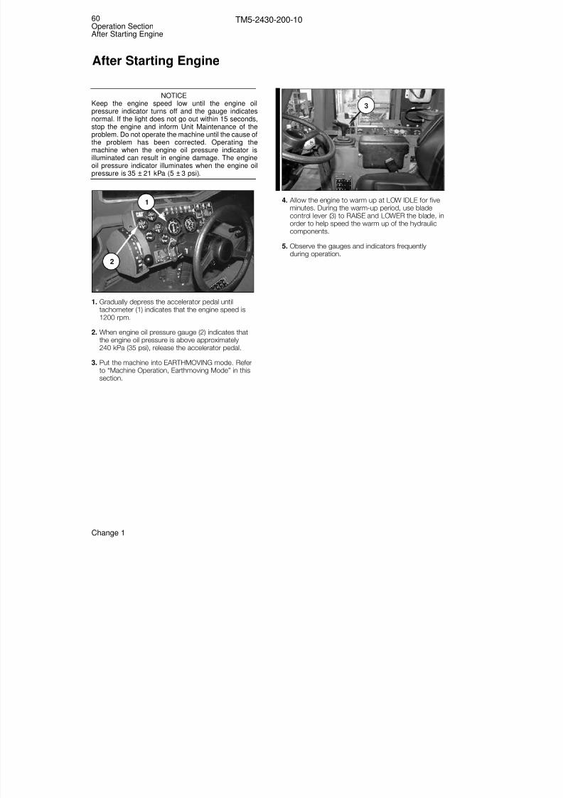
8/3/2019 TM 5-2430-200-10
http://slidepdf.com/reader/full/tm-5-2430-200-10 66/196
NOTICEKeep the engine speed low until the engine oilpressure indicator turns off and the gauge indicatesnormal. If the light does not go out within 15 seconds,stop the engine and inform Unit Maintenance of theproblem. Do not operate the machine until the cause ofthe problem has been corrected. Operating themachine when the engine oil pressure indicator isilluminated can result in engine damage. The engineoil pressure indicator illuminates when the engine oilpressure is 35 ± 21 kPa (5 ± 3 psi).
1. Gradually depress the accelerator pedal untiltachometer (1) indicates that the engine speed is1200 rpm.
2. When engine oil pressure gauge (2) indicates thatthe engine oil pressure is above approximately240 kPa (35 psi), release the accelerator pedal.
3. Put the machine into EARTHMOVING mode. Referto “Machine Operation, Earthmoving Mode” in thissection.
4. Allow the engine to warm up at LOW IDLE for fiveminutes. During the warm-up period, use blade
control lever (3) to RAISE and LOWER the blade, inorder to help speed the warm up of the hydrauliccomponents.
5. Observe the gauges and indicators frequentlyduring operation.
3
1
2
60Operation SectionAfter Starting Engine
TM5-2430-200-10
After Starting Engine
Change 1

8/3/2019 TM 5-2430-200-10
http://slidepdf.com/reader/full/tm-5-2430-200-10 67/196
To minimize whole body vibration, based on 24hour operations, limit daily machine usage to amaximum of 11.5 hours, no more than 4 hourscontinuous; the operator must rest betweenoperations at least 4.16 hours. Failure to complymay result in injury.
Earthmoving Mode
Put the machine in EARTHMOVING mode when usingthe machine for dozing, or ripping. EARTHMOVINGmode may also be used for winching. When themachine is in EARTHMOVING mode:
• the suspension is locked in forward, and active inreverse.
• the transmission is limited to three speeds forward,with manual shifting.
• the engine is limited to the low horsepower setting.
To Place the Machine in EARTHMOVINGMode
1. Stop the machine and place transmission controllever (1) into NEUTRAL.
2. Move the self-deploy/earthmoving switch toEARTHMOVING position (2).
Manual Suspension Locking
Valves are installed on the machine to manually lock the suspension into EARTHMOVING mode. Thesevalves provide a way to lock the suspension if theelectrically operated solenoids do not function.
LOCK— Turn manual suspension lockout valves (3) (onboth sides of the machine) counterclockwise tomanually lock the suspension into EARTHMOVINGmode.
NOTICEDo not operate the machine in SELF-DEPLOY modewhen the suspension is locked by the manuasuspension locking valves. Damage to the machinemay result.
UNLOCK— Turn manual suspension lockout valves(3), on both sides of the machine, clockwise to returncontrol of the suspension locking function to the self-deploy/earthmoving switch.
3
2
1
61Operation Section
Machine Operation
TM5-2430-200-10
Machine Operation
Operation Section
WARNING!
Change 1

8/3/2019 TM 5-2430-200-10
http://slidepdf.com/reader/full/tm-5-2430-200-10 68/196
Self-Deploy Mode
Put the machine into SELF-DEPLOY mode to travel athigh speeds. When the machine is in SELF-DEPLOY mode:
• the suspension is active.
• the transmission will automatically shift between sixspeeds in forward.
• the blade can be raised, angled or tilted, but notlowered.
The blade can be lowered when the machine is inSELF-DEPLOY mode if the electrical power to themachine is off. Always keep clear of the bladewhen the blade is off the ground. Personal injurycan occur.
• the engine operates at the high horsepower settingin transmission speeds three through six.
• the SELF-DEPLOY indicator is lit.
To Place the Machine in SELF-DEPLOY
Mode
1. Stop the machine and place transmission controllever (1) into NEUTRAL.
2. Move blade control lever (2) to LIFT, and raise theblade all the way up.
3. Move self-deploy/earthmoving switch (5) into SELF-DEPLOY position. Self-deploy indicator (4) will turnon. If the self-deploy indicator does not come on,raise the blade further until blade down indicator (3)and blade down alarm (6) turn off.
NOTE: Self-deploy indicator (4) will only function if theblackout light switch is in the SERVICE DRIVE orSTOP LIGHT position.
NOTE: Blade down indicator (3) and blade downalarm (6) will only function if the blackout light switch isin the SERVICE DRIVE or STOP LIGHT position.
3 4
5
6
2
1
WARNING!
62Operation SectionMachine Operation
TM5-2430-200-10

8/3/2019 TM 5-2430-200-10
http://slidepdf.com/reader/full/tm-5-2430-200-10 69/196
Winch Operation
Make sure personnel are clear of wire rope cablewhen there is a load on it. The cable can break andcause personal injury or death.
Thick gloves should be worn when working withcable. Failure to do so may cause severe injury tohands and fingers.
Keep away from the winch fairlead when the cableis retracting. Personal injury due to pinching at thefairlead is possible when the winch cable isretracting.
NOTICEAlways operate the winch with the cable in as straighta line as possible. For winching operation other thanself-recovery, always operate the winch with thetractor in a stationary position. Moving the tractor while
operating the winch may damage the winch.
Refer to “Machine Features, Winch Control Switches”in this section for an explanation of the winch controlswitches, and “Equipment Controls, Winch Controls”in this section for explanation of the winch clutch.
The winch can be operated with the machine in eitherEARTHMOVING or SELF-DEPLOY modes. Use theengine accelerator pedal to control the winch speed.
The rear window screen must be down when thewinch is operated.
The last five wraps of cable must be left on the drumto assist the cable clamp in holding the load.
The winch has a maximum pulling capacity of 97 856 N (22,000 lb). For loads greater than 97 856 N(22,000 lb), use the doubling block which is stored inthe BII compartment (left compartment at the rear of the machine). When the doubling block is used, themaximum pulling force from the doubling block hook is 195 712 N (44,000 lb).
NOTICEThe of the doubling block must be used whenperforming self-rescue of the machine. The winchshould not be used to tow another DEUCE.
Doubling Block Installation
NOTE: The weight of the doubling block is 23 kg(51 lb).
1. Remove cotter pin (3).
2. Turn pin (1) counterclockwise until the end of thepin clears side plate (2).
3. Rotate side plate (2) to allow access to sheave (4).
4. Run winch cable (5) around the sheave. Refer to“Equipment Controls, Winch Controls” in thissection for explanation of the winch clutch.
5. Return side plate (2) to its original position, andreinstall pin (1) and cotter pin (3).
1
5
4
2
3
1
2
3
WARNING!
WARNING!
WARNING!
63Operation Section
Machine Operation
TM5-2430-200-10
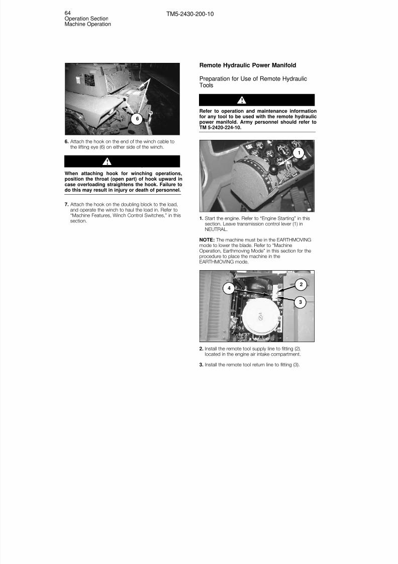
8/3/2019 TM 5-2430-200-10
http://slidepdf.com/reader/full/tm-5-2430-200-10 70/196
6. Attach the hook on the end of the winch cable tothe lifting eye (6) on either side of the winch.
When attaching hook for winching operations,position the throat (open part) of hook upward incase overloading straightens the hook. Failure todo this may result in injury or death of personnel.
7. Attach the hook on the doubling block to the load,and operate the winch to haul the load in. Refer to“Machine Features, Winch Control Switches,” in thissection.
Remote Hydraulic Power Manifold
Preparation for Use of Remote HydraulicTools
Refer to operation and maintenance informationfor any tool to be used with the remote hydraulicpower manifold. Army personnel should refer toTM 5-2420-224-10.
1. Start the engine. Refer to “Engine Starting” in thissection. Leave transmission control lever (1) in
NEUTRAL.
NOTE: The machine must be in the EARTHMOVINGmode to lower the blade. Refer to “MachineOperation, Earthmoving Mode” in this section for theprocedure to place the machine in theEARTHMOVING mode.
2. Install the remote tool supply line to fitting (2),located in the engine air intake compartment.
3. Install the remote tool return line to fitting (3).
42
3
1
WARNING!
WARNING!
6
64Operation SectionMachine Operation
TM5-2430-200-10

8/3/2019 TM 5-2430-200-10
http://slidepdf.com/reader/full/tm-5-2430-200-10 71/196
4. Open the needle valve by turning knob (4)counterclockwise.
5. Lift switch cover (5) and move the remote throttleswitch to ON (up).
NOTE: Remote throttle indicator (6) will illuminate if the blackout switch is in STOP LIGHT or SERVICEDRIVE; engine speed will increase to 2400 rpm; theparking brake will remain engaged, regardless of theposition of knob (3); the accelerator pedal will notfunction; and the transmission will remain inNEUTRAL, regardless of the position of transmissioncontrol lever (1).
6. Use the remote tools in accordance with the
manufacturer’s recommendations.
NOTE: Refer to the operating instructions of theremote hydraulic tool in use for safety precautions andcorrect operating instructions.
Returning Machine to Normal Operation
1. Move the remote throttle switch into the OFFposition, and close switch cover (7).
2. Close the needle valve by turning knob (6)clockwise, until tight.
NOTICEFailure to close the needle valve will cause themachine hydraulic system to not operate withinspecifications.
3. Disconnect the remote tool supply line and remotetool return line from fittings (4) and (5).
65
65Operation Section
Machine Operation
TM5-2430-200-10
Change 1
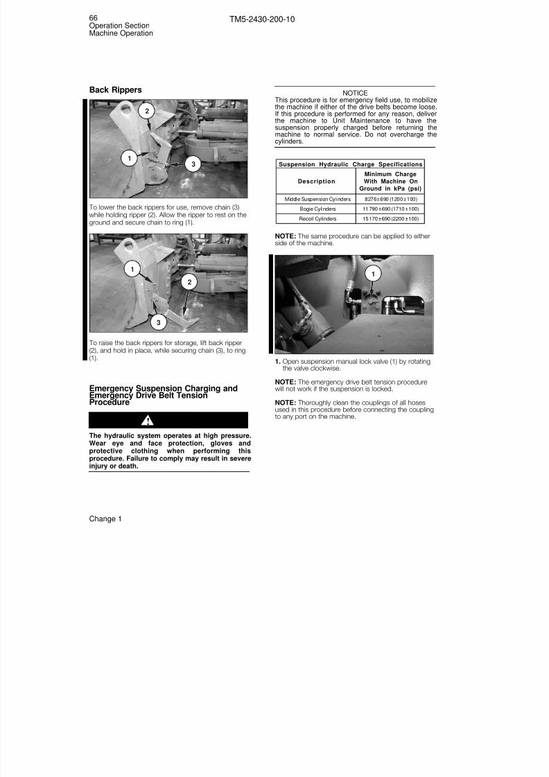
8/3/2019 TM 5-2430-200-10
http://slidepdf.com/reader/full/tm-5-2430-200-10 72/196
Back Rippers
To lower the back rippers for use, remove chain (3)while holding ripper (2). Allow the ripper to rest on theground and secure chain to ring (1).
To raise the back rippers for storage, lift back ripper(2), and hold in place, while securing chain (3), to ring(1).
Emergency Suspension Charging andEmergency Drive Belt TensionProcedure
The hydraulic system operates at high pressure.Wear eye and face protection, gloves andprotective clothing when performing thisprocedure. Failure to comply may result in severeinjury or death.
NOTICEThis procedure is for emergency field use, to mobilizethe machine if either of the drive belts become loose.If this procedure is performed for any reason, deliverthe machine to Unit Maintenance to have thesuspension properly charged before returning themachine to normal service. Do not overcharge thecylinders.
NOTE: The same procedure can be applied to eitherside of the machine.
1. Open suspension manual lock valve (1) by rotatingthe valve clockwise.
NOTE: The emergency drive belt tension procedurewill not work if the suspension is locked.
NOTE: Thoroughly clean the couplings of all hosesused in this procedure before connecting the couplingto any port on the machine.
1
Suspension Hydraulic Charge Specifications
Description
Minimum Charge
With Machine On
Ground in kPa (psi)
Middle Suspension Cylinders 8276 ± 690 (1200 ± 100)
Bogie Cylinders 11 790 ± 690 (1710 ± 100)
Recoil Cylinders 15 170 ± 690 (2200 ± 100)
WARNING!
2
31
66Operation SectionMachine Operation
TM5-2430-200-10
Change 1
3
1
2

8/3/2019 TM 5-2430-200-10
http://slidepdf.com/reader/full/tm-5-2430-200-10 73/196
2. Remove the charge hose and the gauge group fromthe BII compartment. Disconnect coupling (3) fromcoupling (4) on the charge hose. Connect coupling(8) of the gauge group to coupling (4) of the chargehose. Connect coupling (10) of the gauge group tocoupling (3) of the charge hose.
Radiator Shown in Raised Position for Photographic Clarity.
3. Attach coupling (7) to pressure tap (11). Open ballvalve (5) on the charge hose (valve knob is in-linewith valve body).
4. Install coupling (6) to “Recoil Cylinder” fitting (12) atthe rear of the machine.
NOTE: To install coupling (6) to fitting (12), snap thecoupling onto the fitting. Turn nut (2) clockwise until itis hand tight. The hose will turn with the nut.
5. Start the engine. Refer to “Engine Starting” in thissection. Leave transmission control lever (13) inNEUTRAL.
6. Move blade control lever (14) towards the rear of the machine to fully raise the blade.
14
13
12
6 2
5
11
67Operation Section
Machine Operation
TM5-2430-200-10
Change 1

8/3/2019 TM 5-2430-200-10
http://slidepdf.com/reader/full/tm-5-2430-200-10 74/196
Keep personnel clear of the blade while the bladeis raised. The blade could fall, resulting in injuryor death.
7. Move the self-deploy/earthmoving switch to SELF-DEPLOY position (15).
NOTE: The machine must be in the SELF-DEPLOY mode to unlock the suspension. Refer to “MachineOperation, Self-Deploy Mode” in this section for theprocedure to place the machine in the SELF-DEPLOY mode.
8. With the engine operating at low idle, hold auxiliarycharge switch (16) up to direct hydraulic oil into therecoil cylinder.
9. Watch the pressure reading on the pressure gaugeon gauge assembly (9).
10. Release auxiliary charge switch (16) and close ballvalve (5) (turn the valve knob perpendicular to thevalve body) when the pressure reading on thepressure gauge reaches 15 170 kPa (2200 psi).
NOTICEOvertightening the drive belt will cause acceleratedwear of undercarriage components and decreasedmachine performance.
11. Turn nut (2) three-quarters of a turncounterclockwise (this locks the valve). Open ballvalve (5) (turn the valve knob in line with the valvebody).
12. Remove coupling (6) from fitting (12).
13. Repeat Steps 4 and 8 through 11 for the otherdrive belt, if necessary.
14. Remove coupling (7) from pressure tap (11) on themultifunction valve.
15. Turn nut (2) counterclockwise, until the nut stopsrotating (an additional three-quarters of a turn maybe required). Remove coupling (6) from fitting (12).
16. Disconnect coupling (8) of the gauge group fromcoupling (3) of the charge hose. Disconnectcoupling (10) of the gauge group from coupling (4)of the charge hose. Connect coupling (3) tocoupling (4). Return the charge hose and gaugegroup to the BII compartment for storage.
17. Deliver the machine to Unit Maintenance as soonas possible to recharge the suspension.
5
9
16
15
WARNING!
68Operation SectionMachine Operation
TM5-2430-200-10

8/3/2019 TM 5-2430-200-10
http://slidepdf.com/reader/full/tm-5-2430-200-10 75/196
Emergency Machine Leveling
The hydraulic system operates at high pressure.Wear eye and face protection, gloves andprotective clothing when performing thisprocedure. Failure to comply may result in severeinjury or death.
NOTICEThis procedure is for emergency field use to mobilize
the machine. If this procedure is performed for anyreason, deliver the machine to Unit Maintenance tohave the suspension properly charged beforereturning the machine to normal service.
NOTE: Before performing the emergency machineleveling procedure, fully kneel and raise the machinetwice on level ground. Refer to “Machine Features,Kneeling Switch” in this section.
NOTE: The same procedure can be applied to eitherside of the machine.
1. Open suspension manual lock valve (1) by rotatingthe valve clockwise.
NOTE: The emergency machine levelling procedurewill not work if the suspension is locked.
NOTE: Thoroughly clean the couplings of all hosesused in this procedure before connecting the couplingto any port on the machine.
2. Remove the charge hose and the gauge group fromthe BII compartment. Disconnect coupling (3) fromcoupling (4) on the charge hose. Connect coupling(8) of the gauge group to coupling (4) of the chargehose. Connect coupling (10) of the gauge group tocoupling (3) of the charge hose.
Radiator Shown in Raised Position for Photographic Clarity.
3. Attach coupling (7) to pressure tap (11). Open ballvalve (5) on the charge hose (valve knob is in-linewith valve body).
5
11
1
WARNING!
69Operation Section
Machine Operation
TM5-2430-200-10
Change 1
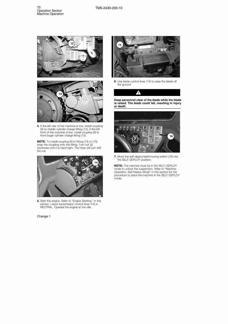
8/3/2019 TM 5-2430-200-10
http://slidepdf.com/reader/full/tm-5-2430-200-10 76/196
4. If the left rear of the machine is low, install coupling(6) to middle cylinder charge fitting (12). If the left
front of the machine is low, install coupling (6) tofront bogie cylinder charge fitting (13).
NOTE: To install coupling (6) to fitting (12) or (13),snap the coupling onto the fitting. Turn nut (2)clockwise until it is hand tight. The hose will turn withthe nut.
5. Start the engine. Refer to “Engine Starting,” in thissection. Leave transmission control lever (14) inNEUTRAL. Operate the engine at low idle.
6. Use blade control lever (15) to raise the blade off the ground.
Keep personnel clear of the blade while the bladeis raised. The blade could fall, resulting in injuryor death.
7. Move the self-deploy/earthmoving switch (16) intothe SELF-DEPLOY position.
NOTE: The machine must be in the SELF-DEPLOY mode to unlock the suspension. Refer to “MachineOperation, Self-Deploy Mode” in this section for the
procedure to place the machine in the SELF-DEPLOY mode.
16
WARNING!
15
14
13
12
70Operation SectionMachine Operation
TM5-2430-200-10
Change 1

8/3/2019 TM 5-2430-200-10
http://slidepdf.com/reader/full/tm-5-2430-200-10 77/196
8. To raise the machine, hold auxiliary charge switch(17) up to direct hydraulic oil into the cylinder.
9. Watch the reading on the gauge and the level of themachine.
NOTE: Do not exceed a maximum pressure of 8276 ±690 kPa (1200 ± 100 psi) when middle cylindercharge fitting (12) is used, and do not exceed amaximum pressure of 11 790 ± 690 kPa (1710 ± 100psi) when the bogie cylinder charge fitting (13) is used.
10. Release auxiliary charge switch (17) and close thevalve (turn the knob perpendicular to the valvebody) on ball valve (5) when the machine is level orwhen the maximum pressure for the cylinder is
reached.
11. Turn nut (2) counterclockwise, until the nut stopsrotating (an additional three-quarters of a turn maybe required).
12. Remove coupling (6) from the fitting of the cylinderwhich was charged.
13. Repeat Steps 4 and 8 through 12 for the othercylinders until the machine is level.
14. Remove coupling (7) from pressure tap (11).
15. Disconnect coupling (8) of the gauge group from
coupling (3) of the charge hose. Disconnectcoupling (10) of the gauge group from coupling (4)of the charge hose. Connect coupling (3) tocoupling (4). Return the charge hose and gaugegroup to the BII compartment for storage.
16. Deliver the machine to Unit Maintenance as soonas possible to recharge the suspension.
Moving the Machine
1. Start the engine. Refer to “Before Starting theEngine” and “Engine Starting” in this section for thestarting procedure.
2. Use blade control lever (1) to raise the blade off theground.
Keep personnel clear of the blade while the bladeis raised. The blade could fall, resulting in injuryor death.
NOTE: If the machine is to be operated in the SELF-DEPLOY mode, the blade must be fully raised.
3. Place self-deploy/earthmoving switch (3) in thedesired position.
3
WARNING!
1
2
3
417
71Operation Section
Machine Operation
TM5-2430-200-10
Change 1
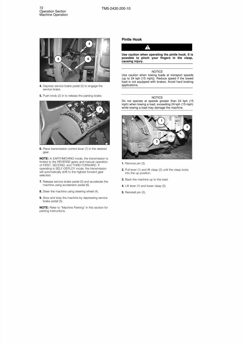
8/3/2019 TM 5-2430-200-10
http://slidepdf.com/reader/full/tm-5-2430-200-10 78/196
72Operation SectionMachine Operation
TM5-2430-200-10
4. Depress service brake pedal (5) to engage theservice brake.
5. Push knob (2) in to release the parking brake.
6. Place transmission control lever (7) in the desiredgear.
NOTE: In EARTHMOVING mode, the transmission islimited to the REVERSE gears and manual operationof FIRST, SECOND, and THIRD FORWARD. If operating in SELF-DEPLOY mode, the transmissionwill automatically shift to the highest forward gearselected.
7. Release service brake pedal (5) and accelerate the
machine using accelerator pedal (6).
8. Steer the machine using steering wheel (4).
9. Slow and stop the machine by depressing servicebrake pedal (5).
NOTE: Refer to “Machine Parking” in this section forparking instructions.
Pintle Hook
Use caution when operating the pintle hook. It ispossible to pinch your fingers in the clasp,causing injury.
NOTICEUse caution when towing loads at transport speeds(up to 24 kph [15 mph]). Reduce speed if the towedload is not equipped with brakes. Avoid hard brakingapplications.
NOTICEDo not operate at speeds greater than 24 kph (15mph) when towing a load. exceeding 24 kph (15 mph)while towing a load may damage the machine.
1. Remove pin (3).
2. Pull lever (1) and lift clasp (2) until the clasp locksinto the up position.
3. Back the machine up to the load.
4. Lift lever (1) and lower clasp (2).
5. Reinstall pin (3).
WARNING!
7
4
65
3
1
2

8/3/2019 TM 5-2430-200-10
http://slidepdf.com/reader/full/tm-5-2430-200-10 79/196
Alert ground support personnel to stay a minimum of 50ft from the deuce during dozing operations. Failure tocomply may result in injury or death from flying rocksand debris.
NOTE: The illustrations in this section are not specific to theDEUCE. However, the techniques described are validoperating techniques for the DEUCE.
Bulldozing
Straight Dozing
For the best performance during straight dozing, a level cutshould be maintained. After the bulldozer blade is filled, theload should be carried to the landfill.
• Do not lug or stall the machine.
• Do not allow the drive belt to spin excessively.
• If the machine must be turned under load, the bulldozer tiltcylinders, not the steering wheel, should be used to steerthe machine.
During leveling work, a full bulldozer blade can be managedmore effectively than a partially loaded blade.
Slot Dozing
NOTICEDuring slot dozing, side wall cave in may occur, potentially
causing damage to the drive belt and suspension..
When material is trapped in a slot, larger loads can be
carried in front of the bulldozer blade.
Once the depth of the slot exceeds the blade height,
production using this method will decreases. Decrease is
due to excess spoil falling back over the blade.
Moderate breaking and reverse gear one (R-1) must beused when backing down any slope. Failure to do socould result in injury or death.
Start at the dump end, and operate rearward. This is shownin Figure (A). This technique permits loading downhill, andthe carrying of a load on a level surface. When working fromthe rear of the slot to the dump end, the previous techniqueis more efficient. This is shown in Figure (B). Uphill loadingdoes not utilize the slot. This is shown in Figure (B). Leveldozing through the entire slot is inefficient, due to the longerdistance of the push.
When parallel slots are dug, the center should be removed
from the rear. This procedure permits the operator to
maintain a slot until the center is removed. The center should
be maintained at a minimum width. The maximum widthshould be approximately one-third of the bulldozer blade.
NOTICE
During earthmoving operations it is possible to collapse the
recoil cylinder completely. To reduce the possibility o
breaking track belts in this condition, a recoil alarm has been
added to the machine to alert the operator to this condition
If the alert sounds, the operator should reverse direction and
clear material from the undercarriage.
WARNING!
WARNING!
73Operation Section
Operating Techniques
TM5-2430-200-10
Operating Techniques
Change 1

8/3/2019 TM 5-2430-200-10
http://slidepdf.com/reader/full/tm-5-2430-200-10 80/196
Machine on a Slope
Moderate breaking and reverse gear one (R-1)must be used when backing down any slope.Failure to do so could result in injury or death.
When possible, a slope should be worked vertically.
Banks or slopes must be worked cautiously to avoidmachine tipping.
If the machine starts to sideslip on a slope, lighten theload and turn the machine downhill.
When a slope is worked horizontally, start at the top of the slope and work downhill. Maintain a windrow of material on the low side of the machine to providestability.
Do not undercut the slope. Undercutting will increasethe slope.
V-Ditching
To V-ditch, tilt the bulldozer blade to the desiredslope. Position the corner of the bulldozer blade in thecenter of the ditch, and cut the ditch to the desireddepth.
Backfilling
Backfill material should be pushed into a trench at a90° angle to the trench. Do not twist the machine on anew backfill. When material is cut on a side slope,material may fall on the machine.
Roading Information
NOTE: Required permits must be obtained before themachine is operated on a public road. Check withlocal officials to determine if permits are required.
Before the machine is driven, Army operators shouldperform the “Operator’s Preventative MaintenanceChecks and Services (OPMCS)” as described in
“Appendix A.”
If a drive belt is loose, perform the proceduredescribed in “Operation Section, Machine Operation,Emergency Suspension Charging, and EmergencyDrive Belt Tension Procedure” in this manual.
Use the SELF-DEPLOY mode when driving themachine on a public road. Refer to “OperationSection, Machine Operation, Self-Deploy Mode” in thismanual.
Place the blackout switch in the position which meetsthe requirements of the current situation. Refer to“Operation Section, Monitoring Systems and CabFeatures, Blackout Light Switch” in this manual.
WARNING!
74Operation SectionOperating Techniques
TM5-2430-200-10

8/3/2019 TM 5-2430-200-10
http://slidepdf.com/reader/full/tm-5-2430-200-10 81/196
The work lights may impair the vision of drivers ofapproaching vehicles, which may cause injury orfatal accidents. Therefore, when traveling onpublic roads or accesses, ensure that the worklight switch is in the OFF position. Refer to“Operation Section, Monitoring Systems and CabFeatures, Work Light Switch” in this manual.
Travel at moderate speeds. Do not exceed the speedlimit on public roads.
NOTE: The maximum travel speed of the machine is48 kph (30 mph). Maximum attainable speed is
dependent on ambient temperature, oil level, and oilweight. The fluids must be at normal operatingtemperature, and the machine must be operated onlevel terrain to reach 48 kph (30 mph).
Reduce travel speed if directional stability isnoticeably diminished. Always use the seat beltwhen operating the machine. Loss of machinecontrol can result in injury or death.
Back Ripping
General Ripping Technique
When the back rippers are used, the machine shouldbe operated in the EARTHMOVING mode with thetransmission in FIRST SPEED REVERSE. If additionalproduction is required, use additional shanks insteadof increasing the ripping speed.
NOTICEWhen ripping is performed, the machine must bedriven in a straight line. Also, all four rippers must be
used at the same time or the rippers must be used insymmetrical pairs.
NOTICEDo not turn the machine while the ripper shanks are inthe ground. The shanks may fail if they are twisted.
Use the accelerator pedal to match the drawbar pullto the underfoot conditions. Do not allow the drive beltto slip.
Rip the ground as deep as the underfoot conditionswill allow. Partial depth ripping may be required.
Remove the material in natural layers.
The depth and width of the pass control the sizing of the ripped material.
The back rippers are not intended for use in rock or indeep ripping applications. Only use the ripper shankswhich are specified in Parts Manual, DeployableUniversal Combat Earthmover (DEUCE).
Ripping Technique for Packed Soil,Hardpan, or Clay
Follow the recommendations given in “General Ripping
Technique,” above.
Use the greatest possible number of shanks to break the material to the desired size. The number of shanksused should not cause the machine to stall or hangup.
NOTE: Four shanks usually work well in thesematerials.
Operation in High AmbientTemperatures (Above 38°C [100°F])
In high ambient temperatures, the gauges must be
checked more often. If a system is overheating,reduce the load, and allow the system to cool tonormal operating temperature.
NOTICE To prevent the fuel from overheating, the fuel leveshould be maintained above one-half of a tankOverheated fuel can cause reduced power and possiblydamage the fuel system.
The operator's preventative maintenance checks andservices should be performed more often than normal.
Refer to “Appendix A, Operator’s PreventiveMaintenance Checks and Services (OPMCS)—DEUCE.” Contact Unit Maintenance for assistance indetermining new maintenance intervals.
WARNING!
WARNING!
75Operation Section
Operating Techniques
TM5-2430-200-10

8/3/2019 TM 5-2430-200-10
http://slidepdf.com/reader/full/tm-5-2430-200-10 82/196
Machine Stopping
NOTE: If possible, park the machine on level ground.If the machine must be parked on a grade, block bothdrive belts on the downhill side of the machine.
1. In preparation to park the machine, releaseaccelerator pedal (3) to decrease engine speed.
2. Depress service brake pedal (2), and movetransmission control lever (1) to a lower gear, toslow the machine travel speed.
3. Fully depress service brake pedal (2) to stop themachine.
With the engine running, this machine will spotturn when the steering wheel is turned, even ifthe transmission is in NEUTRAL.
To avoid personal injury due to unexpectedmovement, engage the parking brake and makesure the area is free of personnel before startingthe engine.
4. Move transmission control lever (1) into NEUTRAL.
5. Pull knob (5) up to engage the parking brake.
NOTE: Service brake pedal (2) can be released afterthe parking brake is engaged.
6. Move the self-deploy/earthmoving switch (6) intoEARTHMOVING position.
7. Move blade control lever (4) forward to LOWER theblade to the ground. Apply a slight downwardpressure with the blade after the blade contacts theground.
NOTE: When the engine is operating, the machinemust be in the EARTHMOVING mode before the bladewill lower. When the engine is not operating,
movement of the blade control lever will allow theblade to lower.
NOTE: If the engine is to be stopped, refer to“Machine Parking, Engine Stopping” in this section forengine shutdown instructions.
6
54
WARNING!
32
1
76Operation SectionMachine Parking
TM5-2430-200-10
Machine Parking
Change 1
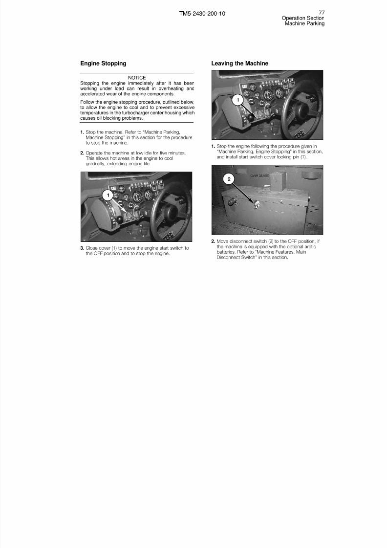
8/3/2019 TM 5-2430-200-10
http://slidepdf.com/reader/full/tm-5-2430-200-10 83/196
Engine Stopping
NOTICEStopping the engine immediately after it has beenworking under load can result in overheating andaccelerated wear of the engine components.
Follow the engine stopping procedure, outlined below,to allow the engine to cool and to prevent excessivetemperatures in the turbocharger center housing whichcauses oil blocking problems.
1. Stop the machine. Refer to “Machine Parking,Machine Stopping” in this section for the procedureto stop the machine.
2. Operate the machine at low idle for five minutes. This allows hot areas in the engine to coolgradually, extending engine life.
3. Close cover (1) to move the engine start switch tothe OFF position and to stop the engine.
Leaving the Machine
1. Stop the engine following the procedure given in“Machine Parking, Engine Stopping” in this section,and install start switch cover locking pin (1).
2. Move disconnect switch (2) to the OFF position, if the machine is equipped with the optional arcticbatteries. Refer to “Machine Features, MainDisconnect Switch” in this section.
2
1
1
77Operation SectionMachine Parking
TM5-2430-200-10

8/3/2019 TM 5-2430-200-10
http://slidepdf.com/reader/full/tm-5-2430-200-10 84/196
3. Open the electrical panel and BII compartment atthe rear of the machine, and turn main disconnect
switch (3) to the OFF position. Refer to “MachineFeatures, Main Disconnect Switch” in this section.
4. If necessary, install padlocks on start switch lockingpin (1), fuel tank cap (4), electrical panel and BII
compartment (5), tool/battery box (6), hydraulic tank cap (7), and cab door (8).
5. Dismount the machine, maintaining three-pointcontact with hand holds (10) and step (9).
6. Inspect back side (11) of the blade and inside (12)of the drive belt components on both sides of themachine for any accumulation of debris. Clean outany debris before the debris hardens.
11
12
8
9
10
7
5 6
4
3
78Operation SectionMachine Parking
TM5-2430-200-10
Change 1

8/3/2019 TM 5-2430-200-10
http://slidepdf.com/reader/full/tm-5-2430-200-10 85/196
General Information
Machine ShippingFor machine shipping specifications, refer to “GeneralSection, Specifications and Model Views” in thismanual.
NOTICERemove any ice, snow or other slippery material fromthe shipping machine and loading dock before loadingthe machine.
Always block the trailer or rail car wheels beforeloading the machine.
Load the machine with the rear end forward to avoiddamage if the cab door opens during transport.
Block the front and rear of the drive belts, and tie themachine down before moving the hauling vehicle.
Cover the engine exhaust opening to prevent theturbocharger from spinning in transit. If the machine isloaded with the rear end towards the front of thetransport vehicle, the rain cap on the exhaust stack must be fastened down.
Comply with regulations governing weight, width and
length of load.
NOTICEProtect the cooling system with an antifreeze mixturerated to the lowest expected temperature on the travelroute, or, drain the cooling system completely after themachine is loaded for transport. If the cooling systemis drained, refill the system before starting the engineto unload the machine. Operating the machine withoutcoolant will damage the engine.
Ground Transportation
1. Drive the machine to the loading area. For operatinginstructions, refer to “Before Starting the Engine,”“Engine Starting,” “After Starting Engine,” and“Machine Parking” in this section.
2. Move blade control lever (1) towards the rear of themachine to fully raise the blade.
3. Place the self-deploy/earthmoving switch (3) intoSELF-DEPLOY position.
4. Drive the machine onto the hauling unit so that therear end of the machine faces forward.
3
1
2
79Operation Section
Transportation Information
TM5-2430-200-10
Transportation Information
Change 1

8/3/2019 TM 5-2430-200-10
http://slidepdf.com/reader/full/tm-5-2430-200-10 86/196
5. With service brake pedal (5) depressed, movetransmission control lever (4) to NEUTRAL.
6. Pull knob (2) up to engage the parking brake beforereleasing service brake pedal (5).
7. Place the self-deploy/earthmoving switch (3) intoEARTHMOVING position.
NOTE: If necessary, the blade can be collapsed toreduce the total shipping width. For the procedure tocollapse the blade, refer to “Special ShippingPreparation” in this section.
8. Move blade control lever (1) towards the front of themachine, and lower the blade until the blade
contacts the bed of the hauling unit.
9. Stop the engine. Refer to “Machine Parking, EngineStopping,” and “Machine Parking, Leaving theMachine” in this section for procedures for stoppingthe engine and leaving the machine.
10. Block the front and rear of each drive belt.
11. Secure the machine to the hauling unit using thetie down locations on each side of the machine.Refer to “Transportation Information, Tie Downs” inthis section for the tie-down locations.
12. Secure engine exhaust cover (6) down to preventwind and water entry into the engine.
13. Secure all windows, doors, and compartmentsbefore shipping the machine.
6
5
4
80Operation SectionTransportation Information
TM5-2430-200-10

8/3/2019 TM 5-2430-200-10
http://slidepdf.com/reader/full/tm-5-2430-200-10 87/196
Machine Roading
Check the travel route for overpass clearances. Makesure there is adequate clearance.
The military load classification for this vehicle is 20. This number is stenciled on the right side of the cab.
Check and obey all local and traffic regulations.
Machine Lifting and Tie Downs
Lifting
Improper lifting can allow the load to shift andcause injury or damage.
One lifting eye (1) is located on either side of theblade. Use these lifting eyes to lift the blade. The bladeshould be fully raised when the machine is lifted.
One lifting eye (2) is located on either side of the C-frame. One lifting eye (3) is located on either side of the winch. Use lifting eyes (1) and (3) to lift themachine. The blade should be fully raised when themachine is lifted.
NOTICEDo not use lifting eyes (2) for single-point lifting whenthe ROPS (top half of cab shell) is installed. Therigging will interfere with the top of the cab. Use liftingeyes (1) for single-point lifting with the ROPS installed
Refer to lifting information plate (4) for lifting andslinging information and the center of gravity location.
The gross vehicle weight of the machine is 16 140 kg(35, 500 lb). The weight given here apply to machinesas manufactured by Caterpillar Inc.
Use properly rated cables and slings for lifting.Position the crane for level lifting.
WARNING!
4
3
1
2
81Operation Section
Transportation Information
TM5-2430-200-10
Change 1

8/3/2019 TM 5-2430-200-10
http://slidepdf.com/reader/full/tm-5-2430-200-10 88/196
Tie Downs
The machine is equipped with 12 tie-down locations:
one (1) on each side of C-frame, four (2) on each sideof machine frame, and two (3) under the winch.
Use an appropriate tie-down method for amachine with a gross vehicle weight ofapproximately 16 140 kg (35,500 lb). Failure toproperly secure the machine during transportcan result in injury or death.
Preparation for Air Transport (C-130,C-141, C-5)
This machine is capable of drive-on and drive-off loading on the C-130, C-141 and C-5 aircraft. Toprepare the machine for drive-on/drive-off, follow theprocedure below. The Aircraft Loadmaster may requireshoring to distribute floor loading. Before the machineis driven on an aircraft, remove antennas and otheritems from the machine which may interfere with theloading process.
NOTICEProtect the cooling system with an antifreeze mixturerated to the lowest expected temperature on the travel
route, or, drain the cooling system completely after themachine is loaded for transport. If the cooling systemis drained, refill the system before starting the engineto unload the machine. Operating the machine withoutcoolant will damage the engine.
Drive On
1. Drive the machine to the loading area.
NOTE: For operating instructions, refer to “BeforeStarting the Engine,” “Engine Starting,” “After StartingEngine,” and “Machine Parking” in this section.
2. Install castor wheels on blade. Refer to “CastorWheel Installation”, in this manual.
a. Move blade control lever (1) towards therear of the machine to fully raise the blade.
1
2
WARNING!
2
3
2
1
82Operation SectionTransportation Information
TM5-2430-200-10
Change 1

8/3/2019 TM 5-2430-200-10
http://slidepdf.com/reader/full/tm-5-2430-200-10 89/196
3. Place blackout light switch (6) in the STOP LIGHT or SERVICE DRIVE position. Refer to “Monitoring
Systems and Cab Features, Switches” in thissection for details about positions of blackout lightswitch (6).
4. Place the self-deploy/earthmoving switch intoSELF-DEPLOY position (7).
5. Move the kneeling switch down to LOWER (4), andhold the switch in the LOWER position untilkneeling indicator (3) illuminates.
With the kneeling switch in the LOWER position,the front of the machine lowers, reducingclearance between the walkways and the drivebelts and also causing the blade position tolower. Keep personnel clear of the machine whenlowering the machine.
6. Use the pump handle to install the kneeling lock pinon both sides of the machine when locking bar (10)aligns with the hole in bracket (9).
NOTE: The kneeling lock pins and pump handle arestored in the electrical panel and BII compartment at
the left rear of the machine.
NOTICEThe kneeling lock pins must be installed to secure themachine in the kneeled position.
Do not operate the machine at speeds greater than 3kph (2 mph) in the kneeled position.
7. Lower all grab rails. Refer to “Machine Features,Grab Rails” in this section.
8. Place the self-deploy/earthmoving switch into
EARTHMOVING position (8).
9. Place the blade in the float position.
10. Move transmission control lever (11) to first gear,and slowly drive the machine onto the aircraft.
11. When the machine is in place on the aircraft,depress service brake pedal (12), and movetransmission control lever (11) into NEUTRAL.
With the engine running, this machine will spotturn when the steering wheel is turned, even ifthe transmission is in NEUTRAL.
To avoid personal injury due to unexpectedmovement, engage the parking brake and makesure the area is free of personnel before startingthe engine.
12. Pull knob (2) up to engage the parking brakebefore releasing service brake pedal (12).
WARNING!
12
11
9
10
WARNING!
7
8
3
4
5
6
83Operation Section
Transportation Information
TM5-2430-200-10
Change 1
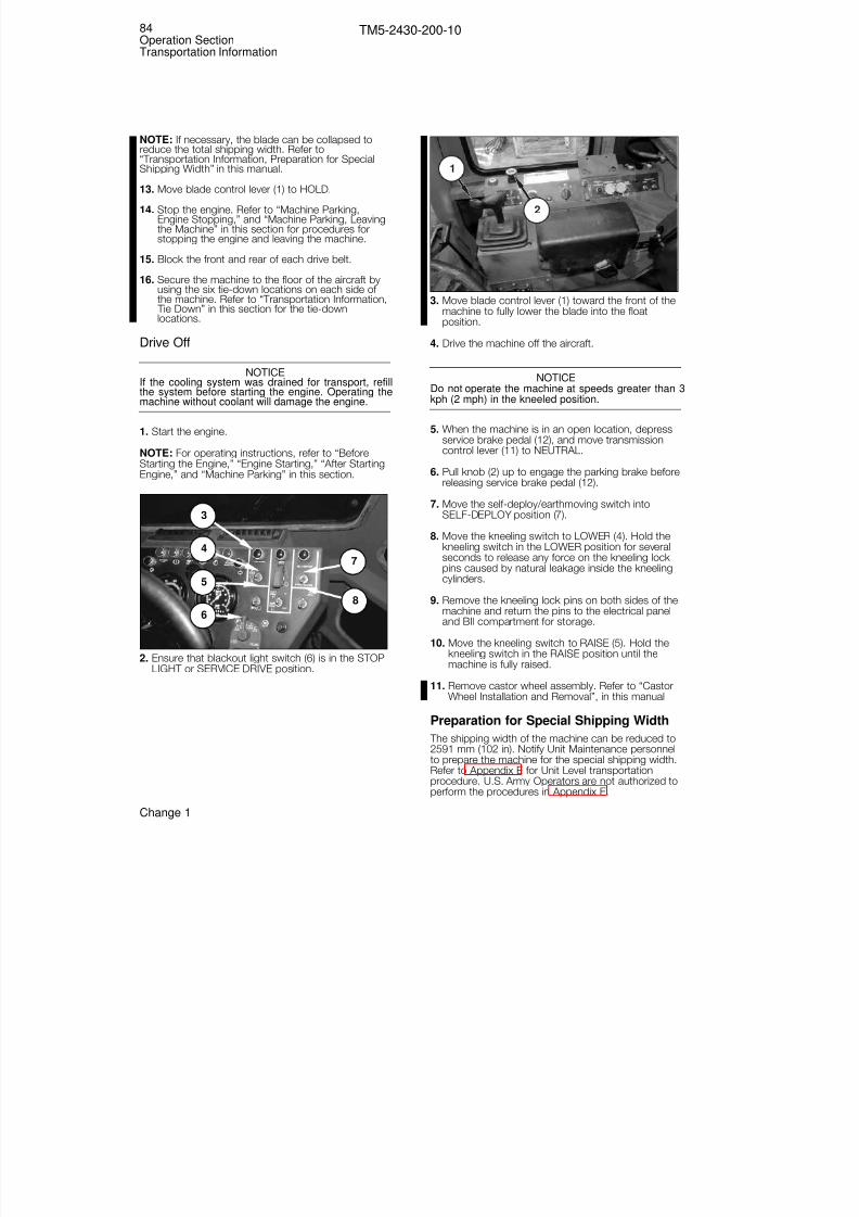
8/3/2019 TM 5-2430-200-10
http://slidepdf.com/reader/full/tm-5-2430-200-10 90/196
NOTE: If necessary, the blade can be collapsed toreduce the total shipping width. Refer to
“Transportation Information, Preparation for SpecialShipping Width” in this manual.
13. Move blade control lever (1) to HOLD.
14. Stop the engine. Refer to “Machine Parking,Engine Stopping,” and “Machine Parking, Leavingthe Machine” in this section for procedures forstopping the engine and leaving the machine.
15. Block the front and rear of each drive belt.
16. Secure the machine to the floor of the aircraft byusing the six tie-down locations on each side of the machine. Refer to “Transportation Information, Tie Down” in this section for the tie-downlocations.
Drive Off
NOTICEIf the cooling system was drained for transport, refillthe system before starting the engine. Operating themachine without coolant will damage the engine.
1. Start the engine.
NOTE: For operating instructions, refer to “BeforeStarting the Engine,” “Engine Starting,” “After StartingEngine,” and “Machine Parking” in this section.
2. Ensure that blackout light switch (6) is in the STOPLIGHT or SERVICE DRIVE position.
3. Move blade control lever (1) toward the front of themachine to fully lower the blade into the floatposition.
4. Drive the machine off the aircraft.
NOTICEDo not operate the machine at speeds greater than 3kph (2 mph) in the kneeled position.
5. When the machine is in an open location, depressservice brake pedal (12), and move transmissioncontrol lever (11) to NEUTRAL.
6. Pull knob (2) up to engage the parking brake beforereleasing service brake pedal (12).
7. Move the self-deploy/earthmoving switch intoSELF-DEPLOY position (7).
8. Move the kneeling switch to LOWER (4). Hold thekneeling switch in the LOWER position for severalseconds to release any force on the kneeling lock pins caused by natural leakage inside the kneelingcylinders.
9. Remove the kneeling lock pins on both sides of themachine and return the pins to the electrical paneland BII compartment for storage.
10. Move the kneeling switch to RAISE (5). Hold the
kneeling switch in the RAISE position until themachine is fully raised.
11. Remove castor wheel assembly. Refer to “CastorWheel Installation and Removal”, in this manual
Preparation for Special Shipping Width
The shipping width of the machine can be reduced to2591 mm (102 in). Notify Unit Maintenance personnelto prepare the machine for the special shipping width.Refer to Appendix E for Unit Level transportationprocedure. U.S. Army Operators are not authorized toperform the procedures in Appendix E.
1
2
7
8
3
4
5
6
84Operation SectionTransportation Information
TM5-2430-200-10
Change 1

8/3/2019 TM 5-2430-200-10
http://slidepdf.com/reader/full/tm-5-2430-200-10 91/196
Personal injury or death could result when towinga disabled machine incorrectly.
Be sure all necessary repairs and adjustmentshave been made before a machine that has beentowed to a service area is put back into operation.
Follow the recommendations below to properlyperform the towing procedure.
NOTICEThe winch cable is rated at 195 712 N (44,000 lb). Thiscable can be used for self-recovery but cannot be used
to tow another DEUCE.
NOTICEThis machine is equipped with internally, spring-applied parking brakes. The parking brakes must behydraulically released before the machine can betowed. Also, the final drives must be disabled beforethe machine is towed. Failure to release the parkingbrake and/or disable the final drives before themachine is towed can damage the machine. NotifyUnit Maintenance to perform these procedures if themachine must be towed.
NOTE: This information is not authorization for theoperator to maintain additional tools or to performmaintenance tasks.
These towing instructions are for moving a disabledmachine a short distance, at low speed (no faster than2 kph [1.2 mph]) to a convenient location for repair. These instructions are for emergencies only. Alwayshaul a disabled machine if long distance moving isrequired.
Shielding must be provided on the towing machine toprotect the operator if the tow line, or bar, shouldbreak. The rear window screen on the DEUCE mustbe down when the machine is towing or being towed.
Do not allow an operator on the machine being towedsince it is not possible to control the steering andbraking.
Before towing, make sure the tow line, or bar, is ingood condition and has enough strength for thetowing situation involved. Use a towing line, or bar,
with a strength of at least 1.5 times the gross weightof the towing machine for a disabled machine stuck in
the mud, or when towing on a grade.
Do not use a chain for pulling. A chain link may break,causing possible injury. Use a wire rope cable withloop or ring ends. An observer (in a safe position)should stop the pulling procedure if the cable starts tobreak or unravel. Stop pulling whenever the pullingmachine moves but the towed machine does not.
Keep the tow angle to a minimum. Do not exceed a30-degree angle from the straight-ahead position.
Quick machine movement could overload the tow line,or bar, and cause it to break. Gradual and smooth
machine movement works better.
Normally, the towing machine should be as large asthe disabled machine. Satisfy yourself that the towingmachine has enough brake capacity, weight andpower, to control both machines for the grade anddistance involved.
To provide sufficient control and braking when towinga disabled machine down a hill, a larger towingmachine or additional machines connected to the frontmay be required. This prevents it from rollinguncontrollably.
All different situational requirements cannot be given,as minimal towing machine capacity is required onsmooth level surfaces, and increased capacity isrequired on inclines or poor surface conditions.
Any towed machine, when loaded onto a trailer, mustbe equipped with its own brake system which isoperable from the operator’s compartment.
When towing the machine, use towing brackets (1) atthe rear of the machine, on both sides of the winch.
1
WARNING!
85Operation Section
Towing Information
TM5-2430-200-10
Towing Information
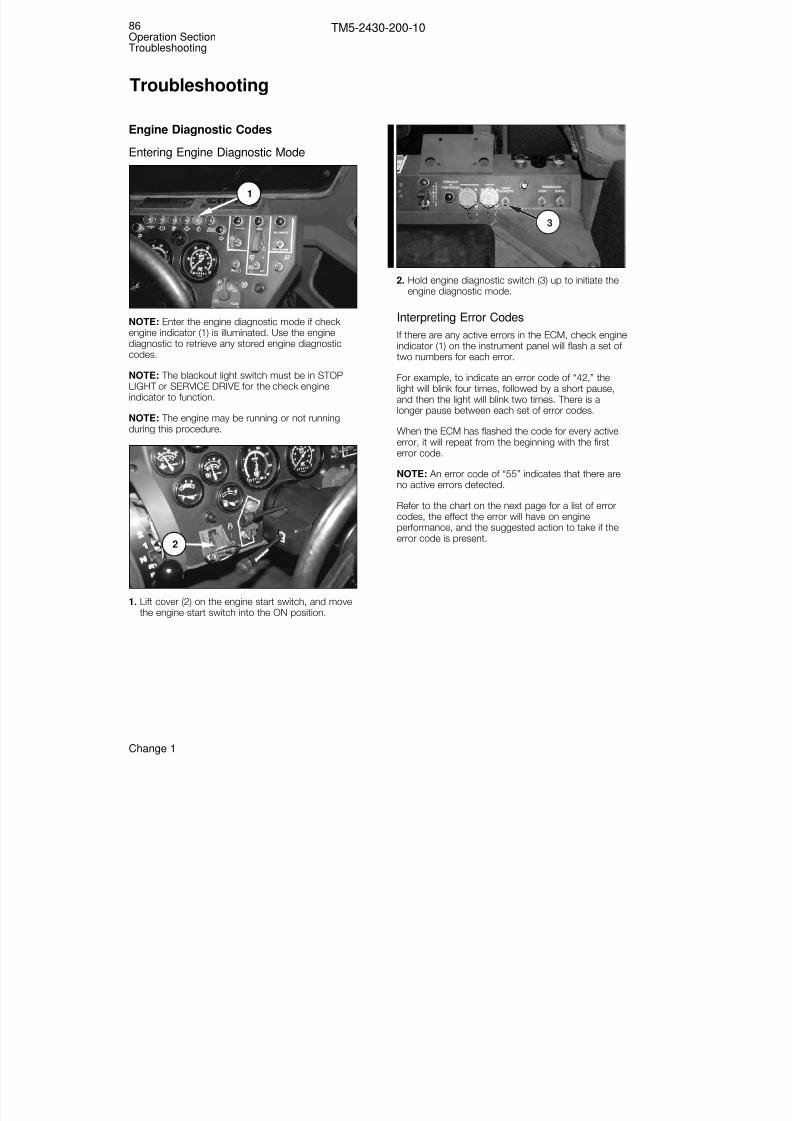
8/3/2019 TM 5-2430-200-10
http://slidepdf.com/reader/full/tm-5-2430-200-10 92/196
Engine Diagnostic Codes
Entering Engine Diagnostic Mode
NOTE: Enter the engine diagnostic mode if check engine indicator (1) is illuminated. Use the enginediagnostic to retrieve any stored engine diagnosticcodes.
NOTE: The blackout light switch must be in STOPLIGHT or SERVICE DRIVE for the check engineindicator to function.
NOTE: The engine may be running or not runningduring this procedure.
1. Lift cover (2) on the engine start switch, and movethe engine start switch into the ON position.
2. Hold engine diagnostic switch (3) up to initiate theengine diagnostic mode.
Interpreting Error Codes
If there are any active errors in the ECM, check engineindicator (1) on the instrument panel will flash a set of two numbers for each error.
For example, to indicate an error code of “42,” thelight will blink four times, followed by a short pause,and then the light will blink two times. There is alonger pause between each set of error codes.
When the ECM has flashed the code for every activeerror, it will repeat from the beginning with the first
error code.
NOTE: An error code of “55” indicates that there areno active errors detected.
Refer to the chart on the next page for a list of errorcodes, the effect the error will have on engineperformance, and the suggested action to take if theerror code is present.
3
2
1
86Operation SectionTroubleshooting
TM5-2430-200-10
Troubleshooting
Change 1

8/3/2019 TM 5-2430-200-10
http://slidepdf.com/reader/full/tm-5-2430-200-10 93/196
Diagnostic Flash Codes
EFFECT ON ENGINE PERFORMANCE
12—Crank-Without-Inject Fault
EngineMisfire
LowPower
Engine SpeedReduced
EngineShutdown
ShutdownMachine
SeAS
15—Injection actuation pressure sensor fault✔ ✔
17—Injection actuation pressure fault ✔ ✔
18—Injection actuation pressure driver fault ✔ ✔
21—Sensor supply voltage fault1 ✔ ✔
25—Boost pressure sensor fault1 ✔
26—Rating select input fault ✔ ✔
27—Coolant temperature sensor fault1
28—Throttle sensor calibration fault ✔
32—Throttle position sensor fault ✔
34—Engine rpm signal fault
37—Engine oil temp sensor fault
38—Inlet manifold temp sensor fault1 ✔
39—Injection actuation pressure system fault ✔ ✔ ✔
42—Timing sensor calibration fault
49—Inlet air heater fault1
51—Low/intermittent power to ECM ✔ ✔
55—No detected faults
56—Check customer/system parameters ✔ ✔
59—Incorrect engine software ✔
72—Cylinder 1 or 2 fault ✔ ✔
73—Cylinder 3 or 4 fault ✔ ✔
74—Cylinder 5 or 6 fault ✔ ✔
88—Ether start relay fault✔
89—Start-aid indicator fault
91—Crank-without-inject indicator fault
SUGGEST
DIAGNOSTIC FLASH CODE/ENGINE PERFORMANCE RELATIONSHIP–3100 HEUI VEHICLE ENGINE (DEUCE)
1 —These diagnostic flash codes may affect the system only under specific environmental conditions, such as engine start-up at cold temperature, cohigh altitude, etc.
Shutdown Machine: Drive the machine to a safe stopping area and get immediate service. Severe engine damage may result.Service ASAP (As Soon As Possible): The operator should go to the nearest qualified service location.Schedule Service: The operator should have the problem investigated when convenient.

8/3/2019 TM 5-2430-200-10
http://slidepdf.com/reader/full/tm-5-2430-200-10 94/196
Operational Troubleshooting
This section describes possible problems andprovides basic solutions to problems which may beencountered during machine operation. This section isonly a guide: not all possible problems and correctionsare addressed. If a problem is not covered, or if theproblem is not corrected by the action described inthis section, refer the problem to Unit Maintenance forresolution.
Problem List
1. Starter Fails to Crank When Start Switch Is Heldin START Position..............................................88
2. Engine Cranks but Will Not Start .......................89
3. Engine Runs Roughly After Starting ...................90
4. Engine Smokes More Than Normal AfterWarm-up........................................................ ...91
5. Engine Overheats During Normal Operation.......91
6. Greater-Than-Normal Fuel Consumption ...........92
7. Greater-Than-Normal Oil Consumption..............93
8. Low Engine Oil Pressure....................................93
9. Engine Stops During Operation .........................93
10.Engine Power Less Than Normal.......................94
11. Transmission Will Not Go in Any Gear ...............94
12. Transmission Will Not Shift into High Gear inSELF-DEPLOY Mode ........................................95
13. Transmission Overheats During NormalOperation ..........................................................95
14.Parking Brake Will Not Release .........................95
15.Service Brakes Slip............................................96
16.Machine Drifts or Pulls to One Side DuringStraight Travel ...................................................96
17.Machine Turns in Opposite Direction ThanExpected During REVERSE Travel .....................96
18.Machine Not Level on Level Ground..................96
19.Hydraulic Functions Erratic or Noisy ..................97
20.Blade Functions Exhibit Less Power ThanNormal ..............................................................97
21.Blade Will Not Lower .........................................97
22. Lights Do Not Work...........................................98
23. Cab Blower Produces Less Air Flow ThanNormal ..............................................................98
24. Recoil Alert Sounds During EarthmovingOperations..................................................... ....98
Problem 1: Starter Fails to Crank When StartSwitch Is Held in START Position
Probable Cause(s):
• Transmission not in NEUTRAL
• Main disconnect switch OFF
• Circuit breaker(s) tripped
• Batteries not providing voltage
1. Transmission not in NEUTRAL:
a. Inspect the position of the transmission controllever. If the transmission control lever is inNEUTRAL, go to Step 2. If the transmissioncontrol lever is not in NEUTRAL, go to Step b.
b. Move the transmission control lever toNEUTRAL, and attempt to start the engineagain. If the engine does not crank, go to Step2.
2. Main disconnect switch OFF:
a. While holding the start switch in the START position, observe the tension fail indicator, thelow brake pressure indicator, the engine oilpressure indicator, and the hydraulic oiltemperature indicator. If any of these lampsilluminates, go to Step 3. If none of these lampsilluminates, go to Step b.
b. Check the position of the main disconnectswitch. If the main disconnect switch is ON, goto Step 3. If the main disconnect switch is OFF,
go to Step c.
c. Move the main disconnect switch to ON, andattempt to start the engine again. If the enginewill not crank, go to Step 3.
3. Circuit breaker(s) tripped:
Reset the following circuit breakers: main, startswitch, ECM, and EPTC II. Attempt to start theengine again. If the engine will not crank, go toStep 4.
88Operation SectionTroubleshooting
TM5-2430-200-10
Change 1

8/3/2019 TM 5-2430-200-10
http://slidepdf.com/reader/full/tm-5-2430-200-10 95/196
4. Batteries not providing voltage:
Batteries produce flammable gasses. Do notsmoke when working around batteries. Openflames or sparks can cause an explosion.
Remove jewelry and dog tags when working withbatteries. Metal shorting across battery poles cancause electrical shock.
Batteries contain a strong acid solution. Wearprotective gloves and safety glasses or goggleswhen working around batteries.
a. With the start switch in the ON position, observethe position of the needle in the voltmeter. If theneedle lies within the first green zone, go to Stepb. If the needle in the voltmeter points to the firstred zone, go to Step c.
b. The batteries are fully charged. Refer theproblem to Unit Maintenance for repair.
c. Inspect the battery for damage, or loose orcorroded connections. Clean and apply greaseto the battery terminals and terminal clamps. Tighten terminal clamps to the battery terminal
clamps. Proceed to Step d.
d. Attempt to start the engine again. If the enginedoes not crank, refer the problem to UnitMaintenance for repair.
Problem 2: Engine Cranks but Will Not Start
Probable Cause(s):
• No fuel or incorrect fuel
• Engine in crank-without-inject mode
• Needle valve open
• Engine oil level low
• Restriction in air intake system
• Cold ambient temperatures
• Batteries not providing sufficient voltage
1. No fuel or incorrect fuel:
Diesel fuel is combustible. Do not smoke whenworking around diesel fuel. Open flames orsparks can cause a fire or explosion.
a. With the start switch in the ON position, observethe position of the needle in the fuel gauge. If theneedle is above the empty mark and there is fuevisible in the tank, go to Step c. If the needle ison the empty mark, go to Step b.
b. Add the correct grade of fuel to the fuel tank,and attempt to restart the engine. If the enginewill not start, go to Step 2.
NOTE: If the fuel system is completely empty, contactUnit Maintenance to prime the fuel system beforeattempting to start the engine.
c. Refer the problem to Unit Maintenance forrepair.
2. Engine in crank-without-inject mode:
a. With the start switch in the ON position and theblackout light switch in STOP LIGHT, observethe crank-without-inject indicator. If the indicatoris not illuminated, go to Step 3. If the indicator is
illuminated, go to Step b.
b. Refer the problem to Unit Maintenance forrepair.
3. Needle valve open:
Ensure that the needle valve on the remotehydraulic tool manifold is closed. Refer to“Maintenance Features, Remote Hydraulic ToolPorts” in this section. If the needle valve is open,close the valve, and attempt to start the engine. If the needle valve is closed, go to Step 4.
4. Engine oil level low:
a. Check the engine oil level. If the engine oil levelis normal, go to Step 5. If the engine oil level islow, go to Step b.
b. Fill the crankcase with the appropriate type of engine oil, and attempt to start the engine againIf the engine does not start, go to Step 5.
5. Restriction in air intake system:
WARNING!
WARNING!
89Operation Section
Troubleshooting
TM5-2430-200-10

8/3/2019 TM 5-2430-200-10
http://slidepdf.com/reader/full/tm-5-2430-200-10 96/196
a. Check the air filter indicator. If red does notappear in the window, go to Step 6. If red
appears in the window, go to Step b.
b. Clean the primary air filter element, and attemptto restart the engine. If the engine does notrestart, go to Step 6.
6. Cold ambient temperatures:
Do not operate the engine coolant heater in anenclosed area. The heater produces combustiongasses which may be harmful. Always start and
operate the heater in a well ventilated area.
a. If the temperature is above approximately 5°C(40°F), go to Step 7. If the temperature isbetween -32°C and approximately 6°C (-25°Fand 40°F), go to Step b. If the temperature isbelow -32°C (-25°F), go to Step e.
b. Observe the start-aid indicator after moving thestart switch from OFF to ON. If the start-aidindicator illuminates for approximately 30seconds, go to Step d. If the start-aid indicatordoes not illuminate, go to Step c.
c. Reset the start-aid circuit breaker and the intakeair heater circuit breaker. Observe the start-aidindicator when the start switch is moved fromOFF to ON. If the start-aid indicator does notilluminate, go to Step 7. If the start-aid indicatorilluminates, go to Step d.
d. Hold start-aid switch in the ON position for threeseconds, and attempt to start the engine. If theengine does not start go to Step 7.
e. Turn the engine coolant heater ON. If theindicator in the engine coolant heater switchilluminates, go to Step g. If the indicator doesnot illuminate, go to Step f.
f. Reset the engine coolant heater circuit breaker,and turn the engine coolant heater ON. If theindicator in the engine coolant heater switchilluminates, go to Step g. If the indicator does notilluminate, refer the problem to Unit Maintenancefor repair.
g. Allow the engine coolant heater to operate for40 minutes. After a three-minute cool downperiod, attempt to start the engine. If the enginedoes not start, go to Step 7.
7. Batteries not providing sufficient voltage:
Follow the procedure given in Problem 1, Step 4.
Problem 3: Engine Runs Roughly After Starting
Probable Cause(s):
• Cold ambient temperatures
• Water in fuel
• Restriction in air intake system
1. Cold ambient temperatures:
Refer to the engine starting procedure for theappropriate air temperature, and follow the steps inthe procedure to start the machine and warm it up.If the machine does not run smoothly after 10minutes, go to Step 2.
2. Water in fuel:
Diesel fuel is combustible. Do not smoke whenworking around diesel fuel. Open flames orsparks can cause a fire or explosion.
a. Check the water separator in the primary fuelfilter for water or sediment. If water or sedimentis not present, go to Step 3. If water or sedimentis present, go to Step b.
b. Drain the water and sediment from the waterseparator into a container, and discard the fluidin accordance with local regulations. Operatethe engine for several minutes. If the enginedoes not run smoothly after several minutes of operation, go to Step 3.
3. Restriction in air intake system:
a. Check the air filter indicator. If red does notappear in the window, refer the problem to UnitMaintenance for repair. If red appears in thewindow, go to Step b.
b. Clean the primary air filter element, and check the engine operation. If the engine does not runsmoothly, refer the problem to Unit Maintenancefor repair.
WARNING!
WARNING!
90Operation SectionTroubleshooting
TM5-2430-200-10
8/3/2019 TM 5-2430-200-10
http://slidepdf.com/reader/full/tm-5-2430-200-10 97/196
Problem 4: Engine Smokes More Than NormalAfter Warm-up
Probable Cause(s):
• Engine wear or mechanical problem• Engine not at normal operating temperature
• Restriction in air intake system
• Incorrect or poor quality fuel
1. Engine wear or mechanical problem:
a. Observe the color of the smoke. If the smoke isdark black or blue, go to Step b. If the smoke iswhite, go to Step 2.
b. Report the problem of more than normal black or blue smoke to Unit Maintenance for repair.
2. Engine not at normal operating temperature:
a. After the engine has idled for approximately fiveminutes, observe the engine coolanttemperature gauge. If the engine coolanttemperature is below normal, go to Step b. If theengine coolant temperature is normal, go toStep 3.
b. While operating the engine at low idle, lift and
lower the blade for several minutes. If the enginecoolant temperature does not increase tonormal, refer the problem to Unit Maintenancefor repair. If the engine coolant temperatureincreases to normal but the white smokeremains, go to Step 3.
3. Restriction in air intake system:
a. Check the air filter indicator. If red does notappear in the window, go to Step 4. If redappears in the window, go to Step b.
b. Clean the primary air filter element, and check
the engine operation. If the white smoke is stillgreater-than-normal, go to Step 4.
4. Incorrect or poor quality fuel:
a. Check the grade of fuel which was last added tothe tank. If the fuel grade is not correct for thecurrent operating environment, go to Step b. If the fuel grade is correct for the operatingenvironment, go to Step c.
b. Report the fuel quality problem to UnitMaintenance.
c. Report the problem of more than normal amountof white smoke to Unit Maintenance for repair.
Problem 5: Engine Overheats During NormalOperation
Probable Cause(s):
• Low engine coolant level
• Low engine or power train oil levels
• Cooler cores blocked
• Cooling fan not operating
• Restriction in exhaust system
• Water to antifreeze ratio too high for operatingenvironment
NOTICEIf the engine is overheating, investigate the causeimmediately. Operating the machine while the engineis overheating may cause damage.
1. Low engine coolant level:
At operating temperature, the engine coolant ishot and under pressure. Any contact with theskin can cause severe burns. Also, coolingsystem additive contains alkalis. Avoid contactwith the skin, eyes, and mouth. Do not open theengine coolant fill cap until the temperature of theengine coolant is below 36°C (98°F).
a. Check the coolant level. If the coolant level is
normal, go to Step 2. If the coolant level isbelow normal, go to Step b.
b. Inspect the machine for visible coolant leaks. If leaks are found, go to Step c. If no leaks arefound, go to Step d.
c. Report the location of the coolant leak to UnitMaintenance for repair.
WARNING!
91Operation Section
Troubleshooting
TM5-2430-200-10

8/3/2019 TM 5-2430-200-10
http://slidepdf.com/reader/full/tm-5-2430-200-10 98/196
d. Check the engine oil level. If the engine oil levelis normal, go to Step 3. If the engine oil level is
low, go to Step 2. If the engine oil level is high,go to Step e.
e. Report to Unit Maintenance that the machine isoverheating and has a possible internal coolantleak.
2. Low engine oil or power train oil level:
a. Check the engine oil level. If the engine oil levelis normal, go to Step c. If the engine oil level islow, go to Step b.
b. Fill the crankcase with the appropriate type of
engine oil, and go to Step c.
c. Check the power train oil level. If the power trainoil level is normal, go to Step 3. If the powertrain oil level is low, go to Step d.
d. Fill power train with the appropriate type of oil,and go to Step 3.
3. Cooler cores blocked:
a. Inspect the fins of the cooler cores for debris. If debris is found, go to Step b. If no debris isfound, go to Step c.
b. Clean the debris from the cooler cores, and goto Step c.
c. Look for evidence of debris in the coolant. If rust, dirt, or a green slime is present, go to Stepd. If the coolant is not contaminated, go to Step4.
d. Report the contamination to Unit Maintenancefor repair.
4. Cooling fan not operating:
a. Inspect the cooling fan. If the cooling fan is not
operating, go to Step c. If the cooling fan isoperating, go to Step b.
b. Listen to the speed of the cooling fan when thecoolant temperature is greater than 100°C(212°F). Allow the engine to cool to 90°C (194°F)or less, and listen to the fan speed. If the fanspeed sounds the same, go to Step c. If the fanspeed is noticeably slower, go to Step 5.
c. Report to Unit Maintenance that the machine isoverheating, and possibly has a cooling fan
problem.
5. Restriction in exhaust system:
a. Inspect the exhaust system for restrictions. If restrictions are found, go to Step b. If norestrictions are found, go to Step 6.
b. Report the location of the restrictions to UnitMaintenance for repair.
6. Water to antifreeze ratio too high for operatingenvironment:
If operating in a hot climate with a highconcentration of antifreeze, inform UnitMaintenance that the machine is overheatingduring normal operation.
Problem 6: Greater-Than-Normal FuelConsumption
Probable Cause(s):
• Restriction in air intake system
• Fuel leak
• Incorrect or poor quality fuel
1. Restriction in air intake system:
a. Check the air filter indicator. If red does notappear in the window, go to Step 2. If redappears in the window, go to Step b.
b. Clean the primary air filter element, and go toStep 2.
2. Fuel leak:
Diesel fuel is combustible. Do not smoke whenworking around diesel fuel. Open flames orsparks can cause a fire or explosion.
The fuel supply lines contain high pressure fluid.Do not use hands to inspect for fuel leaks. Highpressure fluid can penetrate skin.
a. Inspect the fuel system for visible leaks. If leaksare found, go to Step b. If no leaks are found,go to Step 3.
WARNING!
92Operation SectionTroubleshooting
TM5-2430-200-10

8/3/2019 TM 5-2430-200-10
http://slidepdf.com/reader/full/tm-5-2430-200-10 99/196
b. Refer the fuel leak to Unit Maintenance forrepair.
3. Incorrect or poor quality fuel:
Refer the problem of greater-than-normal fuelconsumption to Unit Maintenance for repair.
Problem 7: Greater-Than-Normal OilConsumption
Probable Cause(s):
•Oil needs to be changed
• Oil leakage
• Wrong grade of oil used
• Engine wear
1. Oil needs to be changed:
a. Determine the service meter reading at the lastengine oil change or AOAP reading. If more than250 service hours have elapsed since thatreading, go to Step b. If less than 250 servicehours have elapsed, go to Step 2.
b. Deliver the machine to Unit Maintenance forperformance of a 250 hour maintenance service.
2. Oil leakage:
a. Inspect the machine for visible engine oil leaks. If leaks are found, determine the class of leak (I, II,or III), and then go to Step b. If no leaks arefound, go to Step 3.
b. Report the oil leak to Unit Maintenance forrepair.
3. Engine wear:
a. Observe the color and quantity of exhaust
smoke. If the exhaust smoke is greater-than-normal and blue or black, go to Step b. If theexhaust smoke is of normal quantity and color,go to Step c.
b. Report the greater-than-normal oil consumptionand greater-than-normal amount of exhaust toUnit Maintenance for evaluation.
c. Report the greater-than-normal oil consumptionto Unit Maintenance for evaluation.
Problem 8: Low Engine Oil Pressure
Probable Cause(s):• Low engine oil level
NOTICEStop the engine immediately after low engine oipressure is detected. Operating the engine with low oipressure may damage the engine.
1. Low engine oil level:
a. Check the engine oil level. If the engine oil levelis normal, go to Step e. If the engine oil level is
low, go to Step b.
b. Inspect for visible oil leaks. If leaks are found, goto Step d. If no leaks are found go to Step c.
c. Fill the crankcase with the appropriate type of engine oil, and carefully watch the engine oilpressure during machine operation. Also watchfor engine overheating (refer to “Problem 5,Engine Overheats During Normal Operation” inthis section). If low oil pressure continues, go toStep e.
d. Report the leaks to Unit Maintenance for repair.
e. Report the low oil pressure to Unit Maintenancefor repair.
Problem 9: Engine Stops During Operation
Probable Cause(s):
• No fuel or wrong grade of fuel
• Circuit breaker(s) tripped
• Water in fuel
1. No fuel or wrong grade of fuel:
Diesel fuel is combustible. Do not smoke whenworking around diesel fuel. Open flames orsparks can cause a fire or explosion.
a. Check the fuel level. If the machine has fuel, goto Step c. If the machine does not have fuel, goto Step b.
WARNING!
93Operation Section
Troubleshooting
TM5-2430-200-10

8/3/2019 TM 5-2430-200-10
http://slidepdf.com/reader/full/tm-5-2430-200-10 100/196
b. Add the correct grade of fuel to the fuel tank,and attempt to restart the engine. If the engine
will not start, go to Step 2.
NOTE: If the fuel system was completely empty,contact Unit Maintenance to prime the fuel systembefore attempting to start the engine.
c. Check the grade of fuel which was last added tothe tank. If the fuel grade is not correct for thecurrent operating environment, refer the problemto Unit Maintenance. If the fuel grade is correctfor the current operating environment, go toStep 2.
2. Circuit breakers tripped:
Reset the following circuit breakers: main,alternator, engine control, and transmission control.Refer to “Monitoring Systems and Cab Features,Circuit Breakers” and “Machine Features, MainCircuit Breakers” in this section. Attempt to startthe engine again. If the engine will not start, go toStep 3.
3. Water in fuel:
a. Check the water separator in the primary fuelfilter for water or sediment. If water or sedimentis not present, go to Step c. If water or sediment
is present, go to Step b.
b. Drain the water and sediment from the waterseparator into a container and discard the fluidaccording to local regulations. Attempt to startthe engine. If the engine does not start, go toStep c.
c. Refer the problem to Unit Maintenance forrepair.
Problem 10: Engine Power Less Than Normal
Probable Cause(s)
• Restriction in air intake system
• Poor quality or wrong grade of fuel for operatingconditions
1. Restriction in air intake system:
a. Check the air filter indicator. If red does notappear in the window, go to Step 2. If redappears in the window, go to Step b.
b. Clean the primary air filter element, and operatethe machine. If the engine power is still below
normal, go to Step 2.
2. Poor quality or wrong grade of fuel for operatingconditions:
a. Check the grade of fuel which was last added tothe tank. If the fuel grade is not correct for thecurrent operating environment or the fuel qualityis poor, go to Step b. If the fuel grade is correctfor the current operating environment, go toStep c.
b. Report the fuel grade or quality problem to UnitMaintenance.
c. Report the low power problem to UnitMaintenance for evaluation.
Problem 11: Transmission Will Not Go in AnyGear
Probable Cause(s):
• Parking brake is engaged
• Low power train oil pressure
1. Parking brake is engaged:
a. Release the parking brake and go to Step b.Refer to “Problem 14: Parking Brake Will NotRelease” in this manual.
b. With the service brake depressed, move thetransmission control lever to the desired gear. If the transmission does not go into gear, go toStep 2.
2. Low power train oil pressure:
a. Check the power train oil level. If the power trainoil level is low, go to Step b. If the power train oillevel is normal, go to Step d.
b. Check for visible leaks in the power trainhydraulic system. If leaks are found, go to Stepd. If no leaks are found, go to Step c.
c. Add the appropriate amount and grade of oil tothe power train hydraulic system, and attempt tomove the machine again. If the machine doesnot move, go to Step d.
d. Refer the problem to Unit Maintenance forrepair.
94Operation SectionTroubleshooting
TM5-2430-200-10

8/3/2019 TM 5-2430-200-10
http://slidepdf.com/reader/full/tm-5-2430-200-10 101/196
Problem 12: Transmission Will Not Shift intoHigh Gear in SELF-DEPLOY Mode
Probable Cause(s):
• Machine in EARTHMOVING mode
• Drive belts too tight
• Engine power lower than normal
1. Machine in EARTHMOVING mode:
a. With the blackout light switch in the STOPLIGHT or SERVICE DRIVE position, observe theself-deploy indicator, the blade down indicator,and the blade down alarm. If the self-deploy
indicator is not illuminated, the blade downindicator is illuminated, and the blade downalarm is sounding, go to Step b. If the self-deploy indicator is illuminated, the blade downindicator is not illuminated, and the blade downalarm is not sounding, go the Step 2.
b. Fully raise the blade and observe the self-deployindicator, the blade down indicator and theblade down alarm. If the self-deploy indicator isnot illuminated, the blade down indicator isilluminated, and the blade down alarm issounding, go to Step d. If the self-deployindicator is illuminated, the blade down indicator
is not illuminated, and the blade down alarm isnot sounding, go the Step 2.
c. Operate the machine. If the machine still will notgo into high gear, go to Step 2.
d. Report to Unit Maintenance that the machine isstuck in the EARTHMOVING mode.
2. Drive belts too tight:
a. Determine if the procedures for emergency drivebelt tension or emergency suspension charginghave been performed recently. If either of these
procedures have been completed, go to Step b.If these procedures have not been completed,go to Step 3.
b. Inform Unit Maintenance that the suspensionsystem must be recharged as soon as possible.
3. Engine power lower than normal:
a. Refer to “Problem 10, Engine Power Less ThanNormal” in this section. If low engine power isdetermined not to be the problem, go to Step b.
b. Refer the shifting problem to Unit Maintenancefor repair.
Problem 13: Transmission Overheats DuringNormal Operation
Probable Cause(s):
• Low power train oil level
• Engine or hydraulic system overheating
1. Low power train oil level:
a. Check the power train oil level. If the power trainoil level is low, go to Step b. If the power train oillevel is normal, go to Step 2.
b. Check for visible leaks in the power trainhydraulic system. If leaks are found, go to Stepd. If no leaks are found, go to Step c.
c. Add the appropriate amount and grade of oil tothe power train hydraulic system, and operatethe machine again. If the power train oilcontinues to overheat, go to Step 2.
d. Refer the problem to Unit Maintenance forrepair.
2. Engine or hydraulic system overheating:
a. Determine if the engine or the hydraulic systemis overheating. If either or both of these systemsare overheating, have the problem corrected. If neither of these systems are overheating, go toStep b.
b. Refer the overheating problem to UnitMaintenance for repair.
Problem 14: Parking Brake Will Not Release
Probable Cause(s):
• Service brake not engaged or transmission not inNEUTRAL
• Emergency brake release valve closed
1. Service brake not engaged or transmission not inNEUTRAL:
a. Move the transmission control lever toNEUTRAL. Go to Step b.
95Operation Section
Troubleshooting
TM5-2430-200-10

8/3/2019 TM 5-2430-200-10
http://slidepdf.com/reader/full/tm-5-2430-200-10 102/196
b. Cycle the parking brake ON and OFF. If theparking brake does not release, move the
parking brake switch back to the ON positionand go to Step 2.
2. Emergency brake release valve closed:
a. Turn the needle valve counterclockwise, andattempt to release the parking brake. Refer to“Machine Features, Emergency Brake Release Valve” in this section. If the parking brake doesnot release, go to Step b.
b. Refer the problem to Unit Maintenance forrepair.
Problem 15: Service Brakes Slip
Probable Cause(s):
• Drive belt loose
• Front idlers worn
1. Drive belt loose:
a. Observe the tension fail indicator. If the tensionfail indicator is illuminated, go to Step c. If theindicator is not illuminated, go to Step b.
b. Estimate if the drive belt is sufficiently loose to
cause the brake slippage. If the drive belt isdetermined as the probable cause for the brakeslippage, go to Step c. If the drive belt isdetermined not to be the likely cause of theproblem, go to Step e.
c. Perform an emergency drive belt tensionprocedure, and go to Step d.
d. Inform Unit Maintenance that the suspensionsystem must be recharged as soon as possible.
e. Refer the brake problem to Unit Maintenance forrepair.
2. Front idlers worn:
Report to Unit Maintenance that the front idlersshould be check for excessive wear.
Problem 16: Machine Drifts or Pulls to One SideDuring Straight Travel
Probable Cause(s):
• Drive Belt Loose
1. Drive belt loose:
a. Observe the tension fail indicator. If the tensionfail indicator is illuminated, go to Step c. If theindicator is not illuminated, go to Step b.
b. Visually inspect the belt tension to determine if one drive belt is significantly more loose than theother. If one drive belt is determined to besignificantly more loose than the other, go toStep c. If differences between the tension of thedrive belts cannot be detected, go to Step e.
c. Perform the emergency drive belt tensionprocedure, and go to Step d.
d. Inform Unit Maintenance that the suspensionsystem must be recharged as soon as possible.
e. Refer the problem to Unit Maintenance forrepair.
Problem 17: Machine Turns in OppositeDirection Than Expected During REVERSETravel
Probable Cause(s):
• Circuit breaker tripped
1. Circuit breaker tripped:
a. Check the operation of the gauges or kneelingswitch. If the gauges and kneeling switchfunction properly, go to Step c. If the gaugesand kneeling switch do not function properly, goto Step b.
b. Reset the auxiliary circuit breaker and check thesteering operation in REVERSE. Also check thefunction of the gauges and the kneeling switch.If any of these checks show a malfunction, go toStep c.
c. Report the steering malfunction to Unit
Maintenance for repair.
Problem 18: Machine Not Level on Level Ground
Probable Cause(s):
• One manual suspension lock valve closed
• Suspension system not charged correctly
1. One manual suspension lock valve closed:
96Operation SectionTroubleshooting
TM5-2430-200-10

8/3/2019 TM 5-2430-200-10
http://slidepdf.com/reader/full/tm-5-2430-200-10 103/196
a. Examine the position of the manual suspensionlock valves. If both valves are in the same
position, go to Step 2. If one valve is open andone is closed, go to Step b.
b. Place the machine in the EARTHMOVING mode,and open the manual suspension lock valvewhich was closed. Go to Step c.
c. Place the machine in the SELF-DEPLOY mode,and lower and raise the machine using thekneeling switch. Go to Step d.
d. Determine if the machine is level. If the machineis not level, go to step 2.
2. Suspension system not charged correctly:
a. Determine if the condition of the machineinterferes with the operation of the machine. If the machine cannot be operated in its currentcondition, go to Step b. If the machine can beoperated in its current condition, go to Step c.
b. Perform the emergency machine-levelingprocedure. If the procedure restores themachine to an operational condition, go to Stepc. If the procedure does not change thecondition of the machine, go to Step d.
c. Continue to operate the machine. However,deliver the machine to Unit Maintenance as soonas possible for a complete charging of thesuspension system.
d. Refer the problem to Unit Maintenance forrepair.
Problem 19: Hydraulic Functions Erratic orNoisy
Probable Cause(s)
• Low oil level
1. Low oil level:
a. Check the oil level in the hydraulic tank. If the oillevel is low, go to Step b. If the oil level isnormal, go to Step 2.
b. Examine the hydraulic system for loose fittingsand visible leaks. If loose fittings or leaks arefound, go to Step d. If no loose fittings or leaksare found, go to Step c.
c. Add the appropriate amount and grade of oil tothe hydraulic tank. If the hydraulic functions
continue to be erratic or noisy, go to Step e.
d. Inform Unit Maintenance of the leaks, and havethe leaks repaired as soon as possible.
e. Refer the problem to Unit Maintenance forevaluation.
Problem 20: Blade Functions Exhibit Less PowerThan Normal
Probable Cause(s):
• Needle valve on remote hydraulic power manifold
open
1. Needle valve on remote hydraulic power manifoldopen:
a. Determine if the engine is hard to start and if theengine produces black smoke after starting. If yes, go to Step b. If no, go to Step d.
b. Examine the position of the needle valve on theremote hydraulic power manifold. Refer to“Maintenance Features, Remote Hydraulic ToolPorts” in this section. If the valve is open, go toStep c. If the valve is closed, go to Step d.
c. Close the valve, and observe the operation of the blade functions. If the blade functions stillexhibit less power than normal, go to Step d.
d. Report the low power problem to UnitMaintenance for evaluation.
Problem 21: Blade Will Not Lower
Probable Cause(s):
• Machine in SELF-DEPLOY mode
1. Machine in SELF-DEPLOY mode:
a. Examine the position of the self-deploy/earthmoving switch. If the switch is inEARTHMOVING, go to Step c. If the switch is inSELF-DEPLOY position, go to Step b.
b. Move the self-deploy/earthmoving switch toEARTHMOVING position, and attempt to lowerthe blade. If the blade does not lower, go toStep c.
97Operation Section
Troubleshooting
TM5-2430-200-10

8/3/2019 TM 5-2430-200-10
http://slidepdf.com/reader/full/tm-5-2430-200-10 104/196
c. Report the malfunction to Unit Maintenance forrepair.
Problem 22: Lights Do Not Work
Probable Cause(s):
• Lamps burned out
• Circuit breaker(s) tripped
1. Lamps burned out:
a. If a single indicator will not illuminate when itshould, go to Step b. If multiple lamps do notilluminate when they should, go to Step 2.
b. Report the burned-out indicator to UnitMaintenance for repair.
2. Circuit breaker(s) tripped:
a. If the dome light and remote throttle indicator,start-aid indicator, check engine indicator, winchindicator, and crank-without-inject indicator donot function, go to Step b. If other lamps do notfunction, go to Step c.
b. Reset the horn/dome circuit breaker and thestart-aid circuit breaker, and retest the lamps.Refer to “Monitoring Systems and Cab Features,
Circuit Breakers” and “Machine Features, MainCircuit Breakers” in this section. If the lamps stilldo not function, go to Step c.
c. Report the malfunctioning lamps to UnitMaintenance for repair.
Problem 23: Cab Blower Produces Less Air FlowThan Normal
Probable Cause(s):
• Circuit breaker tripped
• Cab air filters plugged
1. Circuit breaker tripped:
a. Determine if the blower motor operates whenthe blower switch is moved to ON. If the blowerdoes not operate, go to Step b. If the bloweroperates, go to Step 2.
b. Reset the air conditioning and blower motorcircuit breaker. If the blower operates but stillproduces less air flow than normal, go to Step2. If the blower does not operate, go to Step c.
c. Report the blower malfunction to UnitMaintenance for repair.
2. Cab air filters plugged:
a. Clean the external and internal cab air filters. If the blower still produces less flow than normal,go to Step b.
b. Report the diminished air flow to UnitMaintenance for repair.
Problem 24: Recoil Alert
Probable Cause(s):
• Excess material trapped in undercarriage
NOTICEDuring earthmoving operations it is possible tocollapse the recoil cylinder completely. Operation ofthe machine in this condition may cause damage tothe track belts.
1. Excess material trapped in undercarriage.
a. If the recoil alert sounds during earthmovingoperations reverse the direction of the machineto clear any excess material from theundercarriage area.
b. If the recoil alert continues to sound, stop themachine and visually inspect tracks forblockage. Remove any excess debris fromundercarriage area.
c. Report malfunctions to Unit Maintenance forrepair.
98Operation SectionTroubleshooting
TM5-2430-200-10
Change 1

8/3/2019 TM 5-2430-200-10
http://slidepdf.com/reader/full/tm-5-2430-200-10 105/196
General Coolant Information
Water
Distilled or deionized water is recommended for use incooling systems. Do not use hard water, tap water, orsalt softened tap water in engine cooling systems. If distilled or deionized water is not available, use thecleanest water available and have the cooling systemcleaned and the coolant replaced.
NOTICEWater that does not meet the minimum acceptablelimits will reduce engine service life when used incooling systems.
Additives
Additives must be included in all coolant mixtures. Additives help prevent the formation of rust, scale, andmineral deposits. Additives protect metals fromcorrosion, prevent liner cavitation, and contain anti-foaming agents.
NOTICEMIL-A-53009 Supplemental Coolant Additive (SCA) isnot acceptable for use in the engine on this machine.
Glycol
Engine coolant glycol is normally either ethylene orpropylene. Glycol raises the boiling point of water tohelp prevent boil-over, provides freeze protection,helps prevent water-pump cavitation, and reducescylinder liner pitting.
NOTICEFor ambient temperatures requiring lower freezeprotection (higher than 50 percent glycol), useethylene glycol. do not use propylene glycol.
Proper freeze and boil protection requires the properratio of glycol and acceptable water. Use the followingcharts to determine glycol concentrations to mix withacceptable water.
99Maintenance Section
Cooling System Specifications
TM5-2430-200-10
Cooling System Specifications
CH6051
Percentage ofPropylene Glycol
30%
40%
50%
Anti-BoilProtection
102°C (216°F)
104°C (219°F)
106°C (223°F)
FreezeProtection
-15°C (-5°F)
-23°C (-9°F)
-37°C (-35°F)
CH6052
Percentage ofEthylene Glycol
30%
40%
50%
60%
AntiboilProtection
104°C (219°F)
106°C (223°F)
108°C (226°F)
111°C (232°F)
FreezeProtection
-15°C (-5°F)
-24°C (-11°F)
-37°C (-35°F)
-57°C (-71°F)

8/3/2019 TM 5-2430-200-10
http://slidepdf.com/reader/full/tm-5-2430-200-10 106/196
Coolant Recommendations
Preferred—Caterpillar Extended Life Coolant (ELC) ora commercial ELC that meets the Caterpillarspecification (EC-1).
Acceptable—A Caterpillar Diesel Engine Antifreeze/Coolant (DEAC) or a commercial heavy-dutycoolant/antifreeze that meets ASTM D4985, ASTMD5345, or MIL-A-46153 specifications.
Unacceptable—Any high silicate coolant that isclassified as meeting ASTM D3306.
NOTICE
Most commercial engine coolant/antifreeze isformulated for gasoline engine applications andhave a high silicate content. High silicates areconducive to cylinder liner cavitation and corrosion.Caterpillar does not recommend high silicatecoolant/antifreeze.
NOTICENever add coolant to an overheated engine; allow theengine to cool first. Do not add coolant too quickly.Filling the cooling system at over 19 L (5 U.S. gal) perminute can create air pockets in the cooling system.Engine damage can result.
NOTE: MIL-A-4615 Antifreeze can be mixed with theCaterpillar ELC supplied in the DEUCE.
When filling or adding coolant to the system, premixthe coolant solution prior to pouring it into the coolingsystem. Pure, undiluted glycol will freeze at –23°C(-0°F). Use a coolant solution in a range which willprovide protection to the lowest expected outside(ambient) temperature and provide the required boil-over protection.
100Maintenance SectionCooling System Specifications
TM5-2430-200-10

8/3/2019 TM 5-2430-200-10
http://slidepdf.com/reader/full/tm-5-2430-200-10 107/196
Fuel Recommendations
NOTICEFill the fuel tank at the end of each day of operation toremove moist air and prevent condensation. Maintaina constant level in the tank (near the top) to avoiddrawing moisture into the tank as the level decreases.
Do not fill the tank to the top. Fuel expands as itwarms, and may overflow.
Do not fill fuel filters with fuel before installing them.Contaminated fuel causes accelerated wear to fuelsystem parts.
Use only the fuel recommended in this section of thismanual. Fuel grades recommended for use inCaterpillar diesel engines are: No.2-D diesel fuel withlow sulfur (0.05 percent maximum), or regular sulfur(0.5 percent maximum). No.1 grades are acceptable.
The table lists worldwide fuel standards which meetCaterpillar requirements.
Aviation kerosene-type fuels meeting acceptable limitsmay also be used as an engine fuel. The table belowlists some of the acceptable kerosene-type fuels.
101Maintenance Section
Fuel Specifications
TM5-2430-200-10
Fuel Specifications
CH6068
Specifications
American Standards (U.S.)
ASTM D975ASTM D396ASTM D2880
Designated Fuels
No. 1-DNo. 2-D fuel oilNo. 1 fuel oil and No. 2 fuel oilNo. 1-GT fuel for the gas turbineengine and No. 2-GT fuel for thegas turbine engine
British Standards
BS 2869
Class A1 diesel fuelClass A2 diesel fuelClass B1 diesel fuelClass C2 fuel for heating andClass D fuel for heating
German Standards
DIN 51601DIN 51603
Diesel fuel
Australian Standards
AS 3570
Automotive diesel fuel
Japanese Standard
JIS K2204
Type 1 (spl) fuel oilType 1 fuel oilType 2 fuel oilType 3 fuel oilType 3 (spl) fuel oil
U.S. Government
W-F-800CW-F-815C
U.S. DF-1 diesel fuelU.S. DF-2 diesel fuelU.S. DF-20 diesel fuelFS-1 fuel oil for heating andFS-2 fuel oil for heating
U.S. Military Standards
MIL-L-16884G
Marine oil
WORLDWIDE FUEL SPECIFICATIONSFOR DIESEL ENGINES
CH6057
ACCEPTABLE KEROSENE FUELS
Standard DescriptionASTM D 1655-80
MIL-T-83133B
W-F-800F1
Aviation Turbine Fuel (JET A-1)
Aviation Turbine Fuel (JP-8)(NATO Code No. F-34)
Grade DF-A (Arctic)

8/3/2019 TM 5-2430-200-10
http://slidepdf.com/reader/full/tm-5-2430-200-10 108/196
Engine Lubricant Specifications
Diesel Engine Oils The performance of commercial diesel engine oils isbased on API categories. These API categories aredeveloped to provide commercial lubricants for a widevariety of diesel engines that operate at variousconditions.
If Caterpillar DEO (multi-grade) is not used, use onlythe following commercial oils:
Preferred — API CG-4
Allowed — API CF-4
Oils which meet specification MIL-L-2104 areacceptable for use in the engine on this vehicle. Theseoils can be mixed with the preferred and allowed oilsdescribed above.
Caterpillar Transmission/Drive Train Oil(TDTO) (TO-4)—Hydraulic System,Power Train, Offset Arms, Rear Idlers,Midrollers
Caterpillar TDTO TO-4 is balanced to give maximumfrictional material life in power shift transmissions. TO-4 oil specifications include frictional and gear wear
requirements. TO-4 oil is offered in several viscositygrades, including SAE 50, for maximum componentlife at high ambient temperatures and heavy dutycycles.
NOTICETO-4 is formulated for transmissions and drive trainsonly. Using TO-4 in an engine would result inshortened engine life.
Do not use engine oils for lubricating transmissions ordrive trains. Failure to follow this recommendation cancause shortened transmission life due to material
incompatibility and inadequate frictional requirementsfor disk materials.
NOTE: Use of a single viscosity grade MIL-L-2140 oilin the Hydraulic System, Power Train is acceptable.Single viscosity oils which meet MIL-L-2104 can bemixed with the Caterpillar TDTO oils
Caterpillar does not currently offer multigrade oils foruse in transmissions. Multigrade oils which use high
molecular weight polymers as viscosity indeximprovers lose their viscosity effectiveness (permanentand temporary shear), and are therefore notrecommended for transmission and drive traincompartments. The Caterpillar TO-4 specificationincludes a test for multigrade oil shear stability; oilsthat meet this specification may be available in thefuture.
Lubricating Grease
The National Lubricating Grease Institute (NLGI)classifies grease, based on ASTM D217-68 WorkedPenetration characteristics. Grease characteristics are
given a defined consistency number.
Molybdenum Grease: NLGI No. 2 Grade containsthree percent molybdenum disulfide to five percentmolybdenum disulfide. This grease is a multipurposegrease with an operating temperature range from-28°C to 149°C (-18°F to 300°F).
Water and Temperature Resistant Grease: NLGI No.2 Grade is highly resistant to water. This grease meetsthe ASTM D-1264 “Water Washout Test” requirementand resists low temperatures and high temperatures. This grease has a starting torque at -40°C (-40°F) andis not fluid at 316°C (600°F).
102Maintenance SectionLubricant Specifications
TM5-2430-200-10
Lubricant Specifications

8/3/2019 TM 5-2430-200-10
http://slidepdf.com/reader/full/tm-5-2430-200-10 109/196
Lubricant Viscosities
1 Special oils with synthetic base stocks that do not containpolymer viscosity index improvers. The high viscosity index of
the “synthetic” oils provide natural multiviscosity properties.
Refill Capacities
SAE 0W20 (SPC)1
SAE 0W20 (SPC)1
SAE 0W20 (SPC)1
LUBRICANT VISCOSITIES FOR AMBIENT
(OUTSIDE) TEMPERATURES (1)
Compartment Oil °C °F
or System Viscosit ies Min Max Min Max
Engine SAE 0W20 -40 +10 -40 +50
Crankcase DEO SAE15W40 -10 +50 +15 +122
Power Train,SAE 0W20 (SPC)1 -40 +10 -40 +50
Midrollers, Rear SAE 30 0 +35 +32 +95
Idlers SAE 40 +5 +45 +41 +113TDTO
SAE 50 +10 +50 +50 +122
Hydraulic System, -40 +10 -40 +50
SuspensionSAE 10W -20 +40 -4 +104
Cylinders, RecoilSAE 30 +10 +50 +50 +122Cylinders TDTO
-40 +10 -40 +50
SAE 40 +5 +45 +41 +113
SAE 50 +10 +50 +50 +122
Cab/Radiator Tilt
PumpTDTO-40 +50 -40 +122
Winch
Gearbox
TDTO
103Maintenance Section
Lubricant Viscosities and Refill Capacities
TM5-2430-200-10
Lubricant Viscosities and Refill Capacities
REFILL CAPACITIES (APPROXIMATE)
Compartmentor System
LitersU.S.Gal.
ImperialGal.
Cooling System 42 11 9.2
Fuel Tank 341 90 75
Engine Oil With Filter 35 9.2 7.7
Power Train 152 40 33.3
Hydraulic Tank 72 19 15.8
Midrollers .125 4.2 oz 4. 4 oz
Winch Gearbox 1.1 .3 .2
Rear Idlers 1.5 .4 .3
Windshield Washer Bottle 3.8 1.0 .8
Cab/Radiator Tilt Pump 1 .26 .22
Change

8/3/2019 TM 5-2430-200-10
http://slidepdf.com/reader/full/tm-5-2430-200-10 110/196
1 0 4
M a i n t e n a n c e S e c t i o n
L u b r i c a t i o n C h a r t
T M 5 - 2 4 3 0 - 2 0
0 - 1 0
L u b r i c a t i o n
C h
a r t
50
50
50
50
50
250
10
10
50
50
50
10
50
50
50
50
50

8/3/2019 TM 5-2430-200-10
http://slidepdf.com/reader/full/tm-5-2430-200-10 111/196
When Required
Engine Air Intake System—Service Filter.............106
Cab Air System—Service Filters ..........................108
Radiator—Clean Radiator.....................................110
Circuit Breakers—Reset .......................................110
Windshield Wipers—Replace ...............................111
Windshield Washer Fluid—Refill ..........................111
10 Service Hours or Daily
Walk-Around Inspection—Inspect Machine..........112
Seat Belt—Inspect for Damage ............................118
Engine Crankcase—Check Oil Level....................118
Hydraulic Tank—Check Oil Level.........................119
Power Train Oil—Check Oil Level........................120
Radiator—Check Coolant Level ...........................120
Water Separator—Drain Water/Sediment.............121
Indicators, Gauges, Horns and Lights—Check Operation ..............................................121
Brakes—Check Operation ....................................122
Backup Alarm—Check Operation.........................123
Undercarriage—Lubricate................................. ....123
Undercarriage—Check Oil Level ..........................124
Undercarriage—Check Balance ...........................124
50 Service Hours or Weekly*
Undercarriage—Lubricate ....................................125
Undercarriage—Check Oil Level ..........................125
Pintle Hook—Lubricate.........................................126
Blade—Lubricate ..................................................126
250 Service Hours or 3 Months
Cab Pins—Lubricate.............................................127
Winch—Check Hooks, Cable/Lubricate/..............127
Doubling Block......................................................128
Castor Wheel Assembly .......................................128
Engine Coolant Heater—Check Operation...........128
*First perform maintenance items from previousservice intervals.
105Maintenance Section
Maintenance Intervals
TM5-2430-200-10
Maintenance Intervals
Change 1
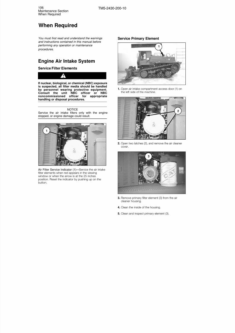
8/3/2019 TM 5-2430-200-10
http://slidepdf.com/reader/full/tm-5-2430-200-10 112/196
You must first read and understand the warnings and instructions contained in this manual before
performing any operation or maintenance procedures.
Engine Air Intake System
Service Filter Elements
If nuclear, biological, or chemical (NBC) exposureis suspected, all filter media should be handled
by personnel wearing protective equipment.Consult the unit NBC officer or NBCnoncommissioned officer for appropriatehandling or disposal procedures.
NOTICEService the air intake filters only with the enginestopped, or engine damage could result.
Air Filter Service Indicator (1)—Service the air intakefilter elements when red appears in the viewingwindow or when the arrow is at the 25 inches
position. Reset the indicator by pushing up on thebutton.
Service Primary Element
1. Open air intake compartment access door (1) onthe left side of the machine.
2. Open two latches (2), and remove the air cleanercover.
3. Remove primary filter element (3) from the aircleaner housing.
4. Clean the inside of the housing.
5. Clean and inspect primary element (3).
3
2
1
1
WARNING!
106Maintenance SectionWhen Required
TM5-2430-200-10
When Required

8/3/2019 TM 5-2430-200-10
http://slidepdf.com/reader/full/tm-5-2430-200-10 113/196
NOTE: For cleaning procedures, refer to “WhenRequired, Cleaning Primary Element,” in this section.
6. Install the clean primary element.
7. Clean and install the air cleaner cover. Closelatches (2).
8. Reset the air filter service indicator.
9. Close air intake compartment access door (1).
NOTE: If the air filter service indicator shows arestriction after cleaning the primary element, haveUnit Maintenance install a new primary and secondaryelement.
Inspect Secondary Element
NOTICENever attempt to clean and reuse a secondary filterelement.
The secondary filter element should be replaced at thetime the primary element is serviced for the third time.
1. Remove air cleaner housing cover (4) and primaryelement (1).
2. Remove secondary element (3).
3. Cover the air inlet opening. Clean the inside of aircleaner housing (2).
4. Inspect the gasket. Have Unit Maintenance replacethe gasket if it is damaged.
5. Inspect secondary element (3) for plugging anddamage.
NOTE: If the secondary element is plugged with dustor damaged, have Unit Maintenance replace the
element.
6. Uncover the air inlet opening. Install secondaryelement (3).
7. Install primary element (1). Install cover (4).
Cleaning Primary Element
NOTICEDo not clean the filter element by bumping or tappingthe element. Do not use a filter element with damagedpleats, gaskets, or seals. Engine damage can result.
Make sure the cleaned filter element is completely drybefore installing it into the filter housing. Wateremaining in the element can cause false indications ocontamination in oil sampling test results.
NOTE: Primary filter elements can be cleaned withpressure water at a maximum of 280 kPa (40 psi), ordetergent washing.
1. Direct water along the pleats inside and outside thefilter element.
NOTE: If the element is washed in warm water and
nonsudsing household detergent, rinse the inside andoutside of the pleats with clean water, and air dry thefilter element completely.
1
2
3
4
107Maintenance Section
When Required
TM5-2430-200-10

8/3/2019 TM 5-2430-200-10
http://slidepdf.com/reader/full/tm-5-2430-200-10 114/196
2. Use a light source to inspect the filter elements aftercleaning. Do not use a filter element with damaged
pleats, gaskets, or seals.
NOTE: If the filter element is damaged, have UnitMaintenance replace the element.
3. Wrap and store the clean filter elements in a clean,dry place.
Cab Air System
If nuclear, biological, or chemical (NBC) exposureis suspected, all filter media should be handledby personnel wearing protective equipment.Consult the unit NBC officer or NBC non-commissioned officer for appropriate handling ordisposal procedures.
Service Filter Elements
Clean the filter elements when a significant reductionin air circulation is noticed. Maximum performance can
not be achieved unless the filter is kept clean.
Before servicing the filters, switch off the blower, closeall windows, and forcibly close the door. The resultingback pressure will dislodge most of the loose dirt fromthe outside of the filters.
NOTE: In humid conditions, such as often occurs inthe early morning, do not switch on the blower prior toservicing the filter. Damp particles drawn into the filtermay be difficult to remove when cleaning.
External Filter
1. Open access door (1) on the right side of the cab.
2. Open latch (2) at the bottom of the filter bracketand remove the bracket.
2
1
WARNING!
108Maintenance SectionWhen Required
TM5-2430-200-10

8/3/2019 TM 5-2430-200-10
http://slidepdf.com/reader/full/tm-5-2430-200-10 115/196
3. Remove air filter element (4) by pulling on tab (3) atthe top or bottom of the filter.
4. Inspect filter element (4) for plugging or damage.
NOTE: If filter element (4) is excessively dirty ordamaged, notify Unit Maintenance that the filterelement must be cleaned or replaced.
5. Clean the filter chamber with a damp cloth.
6. Install filter element (4).
7. Install the filter bracket and close latch (2) at thebottom of the filter bracket.
8. Close access panel (1).
Internal Filter
1. Remove bolt and open access door (1) at the frontof the blower assembly.
2. Remove the filter elements.
NOTE: There are two filter elements installed together.
3. Inspect the filter elements for plugging or damage.
NOTE: If the filter elements are excessively dirty ordamaged, notify Unit Maintenance that the filter
elements must be cleaned or replaced.
4. Clean the filter chamber with a damp cloth.
5. Install the filter elements.
6. Close access door (1) and install the bolt.
1
3
4
109Maintenance Section
When Required
TM5-2430-200-10

8/3/2019 TM 5-2430-200-10
http://slidepdf.com/reader/full/tm-5-2430-200-10 116/196
Radiator
Clean
1. Lift the radiator guard by pulling up sharply on grabrail (1).
2. Prop radiator guard (3) open with prop rod (2).
3. Clean any accumulated debris from the top of cores(4).
NOTICEDo not brush the radiator with your hands, or anotherobject, or you may bend the cooling fins.
4. Return prop rod (2) to its storage location.
5. Lower radiator guard (3), pressing down on it firmlyto secure the guard in place.
Circuit Breakers
Reset
Press the button to reset the following circuit breakerson the front circuit breaker panel:
(1) Engine Control—20 Amps.
(2) Dome/Horns—15 Amps.
(3) Transmission Control—20 Amps.
(4) A/C Blower—15 Amps.
(5) Auxiliary—15 Amps.
Press the button to reset the following circuit breakerson the main circuit breaker panel:
(6) Main—105 Amps
(7) ALT (Alternator)—105 Amps
(8) (Engine Coolant Heater)—30 Amps
(9) AIH (Intake Air Heater)—80 Amps
(10) Start—10 Amps
(11) Ether—15 Amps
10
9
7
6
8
11
1
3
5
4
2
2
4
3
1
110Maintenance SectionWhen Required
TM5-2430-200-10
Change 1
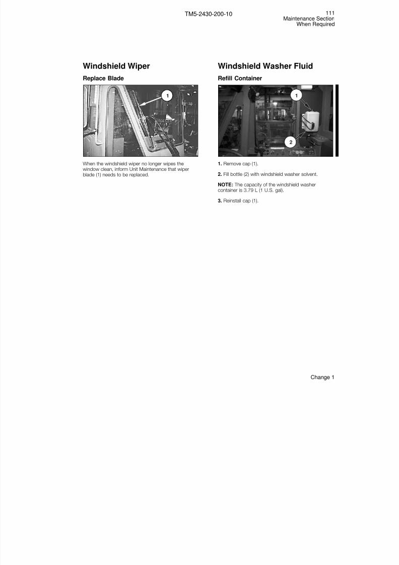
8/3/2019 TM 5-2430-200-10
http://slidepdf.com/reader/full/tm-5-2430-200-10 117/196
Windshield Wiper
Replace Blade
When the windshield wiper no longer wipes thewindow clean, inform Unit Maintenance that wiperblade (1) needs to be replaced.
Windshield Washer Fluid
Refill Container
1. Remove cap (1).
2. Fill bottle (2) with windshield washer solvent.
NOTE: The capacity of the windshield washercontainer is 3.79 L (1 U.S. gal).
3. Reinstall cap (1).
1
2
1
111Maintenance Section
When Required
TM5-2430-200-10
Change 1

8/3/2019 TM 5-2430-200-10
http://slidepdf.com/reader/full/tm-5-2430-200-10 118/196
You must first read and understand the warnings and instructions contained in this manual before
performing any operation or maintenance procedures.
Walk-Around InspectionWhen checking the specific components or areas onthe machine, be alert for oil or fuel leaks, loose ormissing fasteners, filler caps, or identification/safetyplates, and cracked or bent components. Have UnitMaintenance make any needed repairs beforeoperating the machine.
NOTE: Army operators should perform the Operator’s
Preventive Maintenance Checks and Services(OPMCS) before operating the machine. Refer to Appendix A in this manual for the check list.
Undercarriage
Clean away any dirt and debris that has accumulatedin the undercarriage area, then inspect the followingcomponents.
Drive Belts
Have Unit Maintenance replace belts (1) if any of thefollowing conditions are met:
• More than two guide blocks (2) in a row are missing.
• More than 12 guide blocks (2) (one quarter of thetotal number) are missing.
• Belt (1), including internal cables, is severed morethan 40 percent of the width of the track, at anylocation.
Midrollers and Idlers
Have Unit Maintenance repair or replace idlers (3) ormidrollers (4) if the following conditions are met:
• Oil is leaking enough to form drops.
• Oil level is low or not visible in sight gage (5) onoutside midroller or rear idler.
• More than 50 percent of the rubber is missing fromany midroller (4) or more than 25 percent of therubber is missing from any idler (3).
• There are loose or missing bolts.
Swing Arms
Check swing arm pivot joints (6) for loose or missingbolts.
1
2
112Maintenance SectionEvery 10 Service Hours or Daily
TM5-2430-200-10
Every 10 Service Hours or Daily
Change 1
4
3
5
6

8/3/2019 TM 5-2430-200-10
http://slidepdf.com/reader/full/tm-5-2430-200-10 119/196
Cylinders, Accumulators and Hoses
Inspect suspension cylinders (6), accumulators (7),and visible hoses for leaks large enough to formdrops. Use a soft cloth to remove any dirt from thecylinder rods. Check for loose or missing fasteners. If leaks or loose or missing fasteners are found on anycomponent, inform Unit Maintenance.
Drive Wheels and Scraper Bars
Inspect drive wheel (8). Have Unit Maintenance repairor replace the drive wheel/hub if any of the followingconditions are met:
• More than two drive slats in a row, more than four in
a group of ten, or more than six total, are missingfrom a single drive wheel.
• Oil is leaking from the hub severely enough to formdrops.
• There are loose of missing mounting bolts.
Inspect scraper bars (9) for damage and loose ormissing fasteners. Notify Unit Maintenance to repair orreplace the scraper bar if it is bent, the rubber flapsare missing, or if any bolts are loose or missing.
Pin Retention Bolts
Inspect undercarriage pins (10) for loose or missingretention bolts. Inform Unit Maintenance if any loose ormissing retention bolts are found.
Belt Guides
Inspect belt guides (11) for wear and loose or missingbolts. Notify Unit Maintenance if the belt guides areworn enough for holes to form, or if the bolts are looseor missing.
11
10
10
10
9
8
6
7
7
113Maintenance Section
Every 10 Service Hours or Daily
TM5-2430-200-10
Change 1

8/3/2019 TM 5-2430-200-10
http://slidepdf.com/reader/full/tm-5-2430-200-10 120/196
Dozer Blade
Cutting Edge
Inspect cutting edges (2) and end bits (1) for wear anddamage. Have Unit Maintenance replace the cuttingedge or end bits if the adapters are exposed to wear,or if they are broken or cracked. Have UnitMaintenance repair any loose or missing fasteners.
Hydraulic Cylinders and Hoses
Inspect hydraulic cylinders (3) and hoses. Have UnitMaintenance repair or replace any hydraulic cylinder orhose that is leaking enough oil to form drops. HaveUnit Maintenance repair any loose or missing
fasteners.
Back Rippers
Inspect the four back rippers (4) for wear and damage.Have Unit Maintenance replace any missing ripper tips(5), or tips that have worn through to the adapter.Have Unit Maintenance replace any worn or crackedshanks (6) and loose or missing chains (7).
64
5
7
5
6
7
4
3
1
2
114Maintenance SectionEvery 10 Service Hours or Daily
TM5-2430-200-10
Change 1

8/3/2019 TM 5-2430-200-10
http://slidepdf.com/reader/full/tm-5-2430-200-10 121/196
Winch
Inspect winch hydraulic motor (1) and any visiblehydraulic hoses at the rear of the tractor for leaks.Have Unit Maintenance repair or replace the winchmotor or hose if oil is leaking enough to form drops.
Check winch frame (2) for cracks, bends or loose ormissing fasteners. Check for cracked or bent rollers (3)on the fairlead. Have Unit Maintenance repair orreplace the winch if any defects are discovered.
Check the safety latch, if equipped, on hook (4) forcracks, bends, or a loose or missing hinge spring.Have Unit Maintenance repair or replace the safetylatch if any defects are discovered.
Power Train
Check the power train oil level in sight glass (1). Referto “Every 10 Service Hours or Daily, Power Train,Check Oil Level” in this section.
Check for leaks large enough to form drops on allvisible components. Report any leaks found to UnitMaintenance for repair.
Radiator
Raise radiator guard (1), and inspect cooler cores (2).Clean accumulated debris from the top of the coolercores. If debris is lodged between the cooling fins,inform Unit Maintenance that the cooler cores need tobe cleaned.
NOTICEDo not brush the radiator with your hands or anotheobject or you may bend the cooling fins.
Coolant Reservoir
Check the coolant level in coolant reservoir (3). Referto “Every 10 Service Hours or Daily, Radiator, Check Coolant Level” in this section.
3
1
2
1
321
4
115Maintenance Section
Every 10 Service Hours or Daily
TM5-2430-200-10
Change 1

8/3/2019 TM 5-2430-200-10
http://slidepdf.com/reader/full/tm-5-2430-200-10 122/196
Air Filter Compartment
Inspect the following components in the air filtercompartment:
• Check engine oil level (2). Refer to “Every 10 ServiceHours or Daily, Engine Crankcase, Check Oil Level”in this section.
• Check air filter service indicator (1). Refer to “WhenRequired, Engine Air Intake System” in this section.
• Check for oil leaks large enough to form drops onany hoses and components in view.
Oil Filter Compartment
Check the following items in the oil filter compartment:
• Check for leaks large enough to form drops at eachfilter and hose visible in the compartment.
• Check fuel and water separator (1) for water andsediment.
Hydraulic Oil Tank
Check for leaks large enough to form drops. Check the hydraulic oil level in the tank. Refer to “Every 10Service Hour or Daily, Hydraulic Oil Tank, Check OilLevel” in this section.
NOTE: Use the marks on decal (1) to determine thecorrect oil level in the tank. Do not use the marks onthe sight glass.
Cab
Windows and Wiper Blades
Keep windows (2) clean to ensure maximum visibility.
Use a ladder, or other suitable device, to access theupper windows for cleaning. Clean the lower windowsfrom the ground. Use commercially available cleaningsolutions to clean the window.
Check to be sure wiper blades (1) are installed and arenot damaged.
Remove any build-up of dirt, trash or debris from thecab interior. Keep the cab interior clean.
2
1
1
1
1
2
116Maintenance SectionEvery 10 Service Hours or Daily
TM5-2430-200-10

8/3/2019 TM 5-2430-200-10
http://slidepdf.com/reader/full/tm-5-2430-200-10 123/196
Mirrors
Inspect the side mirrors (3) and rear view mirror (4).Have Unit Maintenance replace any damaged ormissing mirrors. Be sure to check the mirroradjustment to get maximum visibility while seated inthe cab.
Gauges
Inspect all gauges on instrument panel (5). Have UnitMaintenance repair or replace any unreadable gauges.
Windshield Washer Fluid Bottle
Refill windshield washer bottle (6) if the level is low.
6
5
4
3
117Maintenance Section
Every 10 Service Hours or Daily
TM5-2430-200-10
Change 1

8/3/2019 TM 5-2430-200-10
http://slidepdf.com/reader/full/tm-5-2430-200-10 124/196
Seat Belt
Inspect for Wear or Damage
Seat belt (1) and mounting hardware (2) must beinspected for wear, damage and expiration before themachine is operated. Have Unit Maintenance replacethe belt or mounting hardware if worn, damaged orexpired.
The seat belt must be replaced after three years of use, regardless of appearance. Tag (4) is sewn intothe belt. Fully extract the belt and check the date onthe tag. If the date on the tag is more than three yearsprior to the current date, report the seat belt to UnitMaintenance for replacement.
Adjust seat position (3) so that all of the machine’scontrols are easy to reach.
Engine Crankcase
Check Oil Level
1. Open air filter compartment door (1) on the left sideof the machine.
2. Maintain the oil level between ADD (4) and FULL (5)marks on dipstick (2) with the engine stopped. Theoil level should be checked when the engine is cold.
NOTE: When operating on severe slopes, the oil levelin the engine must be at the FULL mark on dipstick (2)when the machine is on level ground.
ADD FULL RANGE ENGINE STOPPED
4 5
2
3
2
1
4
2
2
3
1
118Maintenance SectionEvery 10 Service Hours or Daily
TM5-2430-200-10

8/3/2019 TM 5-2430-200-10
http://slidepdf.com/reader/full/tm-5-2430-200-10 125/196
3. Remove oil fill plug (3) and add oil, if necessary.
4. Clean and install oil fill plug (3).
5. Close air intake compartment door (1).
Hydraulic Tank
Check Oil Level
Hydraulic oil tank (1) is located on the right side of themachine.
1. Maintain the oil level in sight gauge (3) between top(4) and bottom (5) marks on the decal to the rear of the sight gauge when the machine is on levelground.
NOTE: Use the marks on the decal to determine thecorrect oil level in the tank. Do not use the marks onthe sight glass.
2. Remove oil fill cap (2) and add oil through the filltube, if necessary.
3. Clean and reinstall oil fill cap (2).
2
3
4
5
1
119Maintenance Section
Every 10 Service Hours or Daily
TM5-2430-200-10

8/3/2019 TM 5-2430-200-10
http://slidepdf.com/reader/full/tm-5-2430-200-10 126/196
Power Train Oil
Check Oil Level
1. Maintain the oil level so that oil is visible in sightgauge (1).
NOTE: Park the machine on flat ground, and check the oil level with the engine not running.
2. Lift the access cover, and remove fill cap (2) andadd oil, if necessary.
3. Clean and reinstall the fill cap.
Radiator
Check Coolant Level
NOTE: Check the coolant level when the engine is atnormal operating temperature. Use the engine coolanttemperature gauge on the instrument panel todetermine the engine’s current temperature.
1. Maintain the coolant level in sight gauge (4)between top (2) and bottom (3) marks on the decal,to the rear of the sight gauge.
2. If necessary, remove cap (1) and add theappropriate mixture of coolant and water for thecurrent operating environment.
3. Clean and replace cap (1).
NOTE: If the coolant reservoir is completely empty,allow the engine to cool to ambient temperature. Afterthe engine is cool, fill the radiator directly throughradiator cap (5). Operate the machine until the enginehas reached normal operating temperature. Addadditional coolant to the coolant bottle through cap(1).
5
1
2
3
4
2
1
120Maintenance SectionEvery 10 Service Hours or Daily
TM5-2430-200-10

8/3/2019 TM 5-2430-200-10
http://slidepdf.com/reader/full/tm-5-2430-200-10 127/196
Water Separator
Drain Water and Sediment
NOTE: The water separator is located in oil filtercompartment (1), on the right side of the machine.
1. Open the oil filter compartment access door.
2. Open drain valve (2) and allow the fuel and watermixture to drain into a suitable container. When nomore water is present in the drain stream, close thedrain valve.
NOTE: Discard the fluid in accordance with localregulations. Ensure that no fuel from the drain valve
drips onto the ground.
3. Close the drain valve.
4. Close the oil filter compartment access door.
Indicators, Gauges, Horn and
LightsCheck Operation
Look for broken gauge lenses, indicator lights,switches, etc.
1. Start the engine. Refer to “Before Starting Engine”and “Engine Starting” in this manual.
2. Check for inoperative gauges on instrument panel(1).
3. Move blackout light switch (8) into the SERVICEDRIVE or STOP LIGHT position, and move hornenable switch (9) to ON.
9
8 10
7
4
1
2
3
5 6
2
1
121Maintenance Section
Every 10 Service Hours or Daily
TM5-2430-200-10

8/3/2019 TM 5-2430-200-10
http://slidepdf.com/reader/full/tm-5-2430-200-10 128/196
4. With the engine running, hold engine start switch (2)in the START position to check the operation of the
indicators (7) on instrument panel (1), and indicators(11) and (12) on the right console. Make note of anyinoperative indicators. Release the start switchwhen the test is complete.
5. Have an assistant activate the recoil alert switch oneach side of the machine to verify that lights (13)and (14), and the alarm (15) function properly.
6. Using blackout switch (8), turn signal switch (5),work lights switch (10), and service brake (4), check all machine lights for correct operation. Refer to“Monitoring Systems and Cab Features, Switches”in this manual for information about indicator
operation.
7. Press button (6) to sound the forward horn.
8. Report any problems found to Unit Maintenance forrepair.
Brakes
Check Operation
1. Start the engine. Refer to “Operation Section,Before Starting Engine” and “Engine Starting” in thismanual.
2. Press and hold service brake pedal (2), then pushdown on knob (4) to release the parking brake.
3. With the service brake still engaged, movetransmission control lever (1) to FIRST FORWARD.
4. Release service brake pedal (2), and move themachine FORWARD very slowly. Refer to “Machine
Operation” and “Machine Parking” in this manual.
5. Press service brake pedal (2) to stop the machine. If the service brake does not stop the machine, pullknob (4) up to engage the parking brake to stop themachine. If the parking brake does not stop themachine, immediately push blade control lever (3)forward to drop the blade, and move transmissioncontrol lever (1) to NEUTRAL.
6. Place the machine in NEUTRAL and engage theparking brake.
34
3
2
1
11 1214
13
15
122Maintenance SectionEvery 10 Service Hours or Daily
TM5-2430-200-10
Change 1

8/3/2019 TM 5-2430-200-10
http://slidepdf.com/reader/full/tm-5-2430-200-10 129/196
7. Report service brake malfunctions to UnitMaintenance for immediate repair.
Backup Alarm
Check Operation
1. Start the engine. Refer to “Operation Section,Before Starting Engine” and “Engine Starting” in thismanual.
2. Place the blackout light switch into STOP LIGHT and the horn enable switch into ON.
3. Press and hold service brake pedal (2), then pushdown on knob (3) to release the parking brake.
4. With the service brake still engaged, movetransmission control lever (1) to FIRST REVERSE.
5. The backup alarm should sound while thetransmission control lever is in FIRST REVERSE.
6. Report backup alarm malfunctions to UnitMaintenance for immediate repair.
3
2
1
123Maintenance Section
Every 10 Service Hours or Daily
TM5-2430-200-10
Change 1

8/3/2019 TM 5-2430-200-10
http://slidepdf.com/reader/full/tm-5-2430-200-10 130/196
Undercarriage
Lubricate
Lubricate four undercarriage fittings on each side of the machine. The four fittings are: (1) tension cylinderpin, (2) front minor bogie pin, (3) major bogie pin, (4)rear minor bogie pin.
NOTE: There are eight undercarriage fittings to belubricated at this service interval.
Check Oil Level
Check oil level in sight gages (5), on outside midrollers(6) and rear idlers (7).
Check Balance
1. Start the engine. Refer to “Operation Section,Before Starting Engine” and “Operation Section,Engine Starting” in this manual.
2. Ensure that the suspension manual lockout valvesare open. Refer to “Operation Section, MachineFeatures, Suspension Manual Lockout Valves” inthis manual.
3. Put the machine into SELF-DEPLOY mode. Refer to“Operation Section, Machine Operation, Self-deployMode” in this manual.
4. Move the machine to a flat surface, and engage theparking brake. Refer to “Operation Section,Machine Operation, Moving the Machine” and“Operation Section, Machine Parking” in thismanual.
5. Check that the left and right side of the machine areapproximately the same distance off the ground.Inform Unit Maintenance that the suspension mustbe recharged if the machine is visibly tilted to theleft or right.
NOTE: If the fenders are bent, another point of reference should be used.
NOTE: If necessary, an emergency suspension
charging can be performed in the field. For theemergency charging procedure, refer to “OperationSection, Machine Operation, Emergency SuspensionCharging” in this manual.
12
3 4
124Maintenance SectionEvery 10 Service Hours or Daily
TM5-2430-200-10
6
7
5
Change 1

8/3/2019 TM 5-2430-200-10
http://slidepdf.com/reader/full/tm-5-2430-200-10 131/196
You must first read and understand the warnings and instructions contained in this manual before
performing any operation or maintenance procedures.
Undercarriage
Lubricate
If operating in temperatures above 38°C (100°F), or invery wet conditions (such as fording), lubricate thefittings at this service interval every 10 service hours ordaily.
Lubricate 14 undercarriage fittings on each side of the
machine. The 14 fittings are: pivot arm (1), bogiecylinder–upper (outer [2] and inner [7]), bogie cylinder-lower (3), middle swing arm (4), rear swing arm (5),rear suspension cylinder–lower (6), middle suspensioncylinder–lower (8), front suspension cylinder–upper (9),middle suspension cylinder–upper (10), rearsuspension cylinder–upper (11), front suspensioncylinder–lower (12), offset arm (13), and front swingarm (14).
NOTE: There are 28 undercarriage fittings to be
lubricated at this service interval.
Check Oil Level
Check oil level in sight gauges (15), on the inside of midrollers (16).
14
12
13
9 10 11
87
1 2
54
3
6
125Maintenance Section
Every 50 Service Hours or Weekly
TM5-2430-200-10
Every 50 Service Hours or Weekly
16
15
Change 1

8/3/2019 TM 5-2430-200-10
http://slidepdf.com/reader/full/tm-5-2430-200-10 132/196
Pintle Hook
Lubricate
Lubricate a total of three fittings on the pintle hook.
Blade
Lubricate
Lubricate four fittings in the tower area of the blade. The four fittings are: (1) angle cylinder–rod end, (2)angle cylinder–head end, (3) singletree–upper, (4)singletree–lower.
On each side of the machine, lubricate three fittings. The three fittings are: (5) lift cylinder–top, (6) liftcylinder–bottom, (7) C-frame.
NOTE: The blade has a total of ten fittings.
5
6
7
1
3
2
4
1
2 3
126Maintenance SectionEvery 50 Service Hours or Weekly
TM5-2430-200-10

8/3/2019 TM 5-2430-200-10
http://slidepdf.com/reader/full/tm-5-2430-200-10 133/196
You must first read and understand the warnings and instructions contained in this manual before
performing any operation or maintenance procedures.
Undercarriage
Cab Pins
Lubricate
Lubricate cab tilt pin fitting (1) on each side of themachine.
NOTE: There are two cab tilt pin fittings.
Winch
Lubricate
Lubricate four fittings on the fairlead rollers of thewinch.
Check Hooks
Check the cable and doubling block hooks. InformUnit Maintenance that the hook must be replaced if itis bent beyond the angle shown above.
Check Cable
Unwind the cable, and check it for kinks and frays.Have Unit Maintenance replace the cable if it is kinkedworn or frayed.
NOTE: For more information, refer to FM-5-125,Rigging, Techniques, Procedures, and Applications.
10° 10°
2
4
3
1
1
127Maintenance Section
Every 250 Service Hours or Monthly
TM5-2430-200-10
Every 250 Service Hours or 3 Months
Change 1

8/3/2019 TM 5-2430-200-10
http://slidepdf.com/reader/full/tm-5-2430-200-10 134/196
Doubling Block
Lubricate
Lubricate the doubling block. There is one fitting.
NOTE: The doubling block is normally stored in the BIIbox.
Castor Wheel Assembly
Lubricate
Lubricate castor wheel assemblies (1). There are two
fittings (2), one on each side of the wheel.
NOTE: There are two castor wheel assemblies. Theyare normally stored in the BII box.
Engine Coolant Heater
Check Operation
NOTE: The engine coolant heater is an option that isinstalled with the arctic starting system. Thisprocedure does not need to be performed if theengine coolant heater is not installed.
Operate the optional engine coolant heater to keepthe unit functioning correctly. This procedure shouldbe performed before the engine is started in themorning, while the engine coolant is still at ambienttemperature.
NOTE: Do not start the engine.
1. Press engine coolant heater switch (1) to turn thesystem on. The lamp inside the coolant heaterswitch will turn on when the system is operating.
2. Allow the engine coolant heater to operate for 10 or15 minutes, and then press engine coolant heaterswitch (1) again to turn the coolant heater off.
3. Wait until the lamp inside the coolant heater switchturns off (at least three minutes) before starting theengine.
NOTICEDo not start the engine while the light in the enginecoolant heater switch is on. The engine coolant heaterrequires three minutes to purge itself of diesel fumes.Damage to the engine coolant heater may result if theengine is started too soon after use.
1
5
128Maintenance SectionEvery 250 Service Hours or Monthly
TM5-2430-200-10
2
1
Change 1

8/3/2019 TM 5-2430-200-10
http://slidepdf.com/reader/full/tm-5-2430-200-10 135/196
A
Additives..................................................................99 After Starting Engine................................................60 Air Conditioning .......................................................32 Air Conditioning/Heating Controls............................32 Air Transport (C–130, C–141, C–5), Preparation for
...........................................................................82 Alternate Exit ...........................................................32 Arm Rest .................................................................30 Auxiliary Start Receptacle (NATO Slave)...................41
B
Back Rippers.....................................................50 ,66Back Rippers, Inspect ...........................................114
Backup Alarm........................................................123Before Starting the Engine.......................................52Belt Guide, Inspect ...............................................113BII Compartment .....................................................49Blackout Light Switch..............................................21Blade, Lubricate ....................................................126Blade Controls.........................................................50Blade Down Indicator ..............................................26Brake Release Valve, Emergency.............................49Brake Switch, Parking .............................................38Brake, Parking.........................................................38Brakes, Check Operation.......................................122Brakes, Service .......................................................38
CCab Air System, Service Filter Elements ................108Cab Door ................................................................31Cab Pins, Lubricate ...............................................127Cab/Radiator Tilt Controls .......................................45California, Proposition 65 Warning .............................3Cap, Engine Coolant Fill ..........................................47Cap, Fuel Tank Fill ...................................................48Cap, Hydraulic Oil Tank Fill ......................................48Cap, Power Train Oil Fill ..........................................48Castor Wheel Assembly, Lubricate ........................128Caterpillar Transmission/Drive Train Oil (TDTO) (TO-4)
.........................................................................102
Check Engine Indicator............................................26Circuit Breakers.......................................................33Circuit Breakers, Main .............................................41Circuit Breakers, Reset ..........................................110Coat Hook...............................................................37Coolant Information, General ...................................99Coolant Recommendations ...................................100Coolant Reservoir, Inspect.....................................115Coolant Temperature Gauge....................................24Cooling Fan .............................................................29Cooling System Specifications.................................99Crank-Without-Inject Indicator .................................26
Cutting Edge, Inspect ............................................114Cylinders, Accumulators and Hoses, Inspect .........113
D
Decontamination Container Bracket.........................46Diagnostic Codes, Engine........................................86Diesel Engine Oils ..................................................102Disconnect Switch, Main .........................................40Door, Cab ...............................................................31Doubling Block
Installation ...........................................................63Lubricate...........................................................128
Dozer Blade...........................................................114Drive Belt Tension, Emergency ................................66Drive Belts, Inspect................................................112Drive Off ..................................................................84Drive Wheels And Scraper Bars, Inspect ...............113Drive-on...................................................................82
E
Earthmoving Mode ..................................................61Electrical Panel and BII Compartment and
Tool/Battery Compartment..................................49Emergency Brake Release Valve..............................49Emergency Drive Belt Tension Adjustment
Controls ..............................................................45Emergency Machine Leveling...................................69Emergency Suspension Charging and Emergency
Drive Belt Tension Procedure ..............................66
Engine Air Intake System.......................................106Cleaning Primary Element..................................107Filter Elements, Service .....................................106Inspect Secondary Element...............................107Primary Element, Cleaning.................................107Secondary Element, Inspect..............................107Service Filter Elements ......................................106Service Primary Element....................................106
Engine Controller Diagnostic Port ............................19Engine Coolant Fill Cap ...........................................47Engine Coolant Heater...........................................128Engine Coolant Heater Switch ................................18Engine Coolant Temperature Gauge........................24Engine Crankcase, Check Oil Level .......................118Engine Diagnostic Codes.........................................86Engine Diagnostic Switch ........................................19Engine Lubricant Specifications ............................102Engine Oil Pressure Gauge ......................................24Engine Oil Pressure Indicator ...................................26Engine Oils, Diesel .................................................102Engine RPM Gauge .................................................24Engine Start Switch .................................................17Engine Starting ........................................................54Engine Starting Above 0°C (32°F) ............................54Engine Starting Below –32°C (–25°F).......................57Engine Starting Between 0°C and –32°C
(32°F and -25°F) .................................................56
129Index Section
Index
TM5-2430-200-10
Index
Change 1

8/3/2019 TM 5-2430-200-10
http://slidepdf.com/reader/full/tm-5-2430-200-10 136/196
Engine Starting with Auxiliary Start (NATO Slave)Receptacle..........................................................58
Engine Stopping ......................................................77Equipment Controls.................................................50Every 10 Service Hours or Daily.............................112Every 250 Service Hours or 3 Months ...................127Every 50 Service Hours or Weekly .........................125Exit, Alternate ..........................................................32External Filter.........................................................108
F
Fan, Cooling............................................................29Fire Extinguisher Bracket .........................................46Fluid Bottle, Windshield Washer...............................36Foreword...................................................................3
Fuel Level Gauge.....................................................25Fuel Recommendations .........................................101Fuel Specifications.................................................101Fuel Tank Fill Cap ....................................................48
G
Gauges....................................................................24Gauges, Inspect ....................................................117General Coolant Information ....................................94General Information, Transportation .........................79Glycol ......................................................................99Grab Rails ...............................................................47Grease, Lubricating ...............................................102
Ground Transportation.............................................79Guard, Rear Windshield...........................................37
H
Hazard Warning Lights ............................................29Heating....................................................................32Horn ........................................................................28Horn Enable Switch.................................................20Hydraulic Cylinders, Inspect...................................114Hydraulic Oil Tank Fill Cap.......................................48Hydraulic Oil Temperature Indicator .........................28Hydraulic Tank, Check Oil Level.............................119
I
Important Safety Information......................................4Indicator Check Function.........................................27Indicators ................................................................25Indicators, Gauges, Horn and Lights, Check
Operation ..........................................................121Interior Light ............................................................30Internal Filter, Cab .................................................109
K
Kneeling Indicator ....................................................26Kneeling Lock Pin....................................................44Kneeling Switch.......................................................42
L
Leaving the Machine................................................77Lifting ......................................................................81Literature Information.................................................3Lockout Valves, Suspension Manual........................46Low Brake Pressure Indicator..................................25Lubricant Specifications.........................................102Lubricant Viscosities ..............................................103Lubricant Viscosities and Refill Capacities..............103
Lubricating Grease ................................................102Lubrication Chart ...................................................104
M
Machine Description ..................................................3Machine Features ....................................................38Machine Leveling, Emergency..................................69Machine Lifting and Tie Downs................................81Machine Operation ..................................................61Machine Parking......................................................76Machine Pre-Start Checks.......................................52Machine Roading.....................................................81Machine Shipping....................................................79
Machine Stopping ...................................................76Main Circuit Breakers ..............................................41Main Disconnect Switch ..........................................40Maintenance..............................................................3Maintenance Intervals ............................................105Manual Suspension Locking ....................................61Midrollers and Idlers, Inspect .................................112Mirrors.....................................................................35Mirrors, Inspect .....................................................117Monitoring Systems and Cab Features ....................17Moving the Machine ................................................71
O
Operation ..................................................................3Operating Techniques..............................................73
Bulldozing ...........................................................73Roading Information ............................................75Back Ripping.......................................................75
Operational Troubleshooting ....................................88
130Index SectionIndex
TM5-2430-200-10
Change 1

8/3/2019 TM 5-2430-200-10
http://slidepdf.com/reader/full/tm-5-2430-200-10 137/196
P
Parking Brake..........................................................38Parking Brake Switch ............................................113Pin Retention Bolts, Inspect...................................110Pin, Kneeling Lock...................................................44Pintle Hook........................................................46, 72
Lubricate...........................................................126PLGR Bracket .........................................................35PLGR/SINCGARS Power Strip ................................36Power Strip, PLGR/SINCGARS ...............................36Power Train Oil, Check Oil Level............................120Power Train Oil Fill Cap ...........................................48Preparation for Air Transport (C–130, C-141, C-5)...82Preparation for Special Shipping Width....................84Preparation for Use of Remote Hydraulic Tools........64
Problem List ............................................................88Product Identification and Serial Number
Locations ............................................................15Proposition 65 Warning .............................................3
R
Radiator.........................................................110, 120Check Coolant Level .........................................120Clean ................................................................110
Rear View Mirror......................................................35Rear Windshield Guard............................................37Recoil Alert ........................................................27, 98Refill Capacities, Lubricant Viscosities and.............103
Remote Hydraulic Power Manifold ...........................64Remote Hydraulic Tool Ports ...................................44Remote Throttle Indicator ........................................27Remote Throttle Switch ...........................................42Returning Machine to Normal Operation ..................65Rifle Bracket ............................................................36Rippers, Back....................................................50 ,66Roading, Machine....................................................81
S
Safety....................................................................3 ,4Safety, Alternate Exit................................................11Safety, Batteries ......................................................10
Safety, Before Operating the Machine .....................12Safety, Before Starting the Engine ...........................11Safety, Burn Prevention ...........................................10Safety, Coolant........................................................10Safety, Crushing or Cutting Prevention ......................9Safety, Engine Starting ............................................12Safety, Ether............................................................11Safety, Fire Extinguisher...........................................10Safety, Fire or Explosion Prevention.........................10Safety, Fluid Penetration ............................................9Safety, General Hazard Information ...........................8Safety, Lines, Tubes and Hoses ..............................11
Safety, Machine Operation.......................................12Safety, Machine Parking ..........................................13
Safety, Mounting and Dismounting ..........................11Safety, Oils ..............................................................10Safety, Performance of Maintenance .........................9Safety, Pressure Air ...................................................9Safety, Rollover Protective Structure (ROPS) or
Falling Objects Protective Structure (FOPS)...........9Seat Adjustment ......................................................35Seat and Seat Belt Checks......................................52Seat Belt .................................................................34
Inspect for Wear of Damage..............................118Self-Deploy Mode....................................................62Self-Deploy Mode Indicator......................................26Self-Deploy/Earthmoving Mode Switch ....................43Service Brakes ........................................................38
Shipping Width, Preparation for Special...................84Side Window ...........................................................32SINCGARS Bracket Installation................................36Specifications and Model Views...............................14Speedometer...........................................................24Start Receptacle, Auxiliary .......................................41Start-Aid Indicator ...................................................26Start-Aid Switch ......................................................18Steering Column......................................................28
Extend/Retract ....................................................29 Tilt.......................................................................28
Steering Wheel ........................................................39Suspension Charging and Drive Belt Tension,
Emergency..........................................................66
Suspension Locking, Manual ...................................61Suspension Manual Lockout Valves.........................46Swing Arms, Inspect..............................................112Switch, Kneeling......................................................43Switch, Self-Deploy/Earthmoving Mode ...................43Switch, Winch Control .............................................43Switch, Winch Enable ..............................................43
T
Table of Contents ......................................................1 Tension Fail Indicator...............................................25 Throttle Switch, Remote ..........................................42 Tie Downs ...............................................................82
Tool Ports, Remote Hydraulic ..................................44 Tool/Battery Compartment ......................................49 Towing Information ..................................................8 Transmission Control Lever .....................................39 Transmission Controller Diagnostic Port...................19 Transmission Diagnostic Check Switch....................19 Transmission Diagnostic Scroll Switch.....................19 Transmission Oil Temperature Gauge ......................24 Transportation Information .......................................79 Transportation, Ground............................................79 Troubleshooting.......................................................86 Turn Signal ..............................................................28
131Index Section
Index
TM5-2430-200-10
Change 1

8/3/2019 TM 5-2430-200-10
http://slidepdf.com/reader/full/tm-5-2430-200-10 138/196
Turn Signal Indicator................................................26
U
Undercarriage................................................123, 125Check Balance..................................................124Lubricate...........................................................123Lubricate...........................................................125
V
Ventilation Louvers...................................................33 Voltmeter.................................................................24
W
Walk-Around Inspection.........................................112 Air Filter Compartment ......................................116Cab...................................................................116Dozer Blade ......................................................114Hydraulic Oil Tank .............................................116Oil Filter Compartment ......................................116Power Train.......................................................115Radiator ............................................................115Seat Belt ...........................................................118Undercarriage....................................................112Winch................................................................115
Warning Labels..........................................................5Washer/Wiper Control .............................................28Water ......................................................................99
Water Separator, Drain Water and Sediment .........121When Required......................................................106Winch....................................................................127
Check Cable .....................................................127Check Hooks ....................................................127Inspect ..............................................................115Lubricate...........................................................127
Winch Clutch...........................................................51Winch Control Switch ..............................................43Winch Control Switches...........................................43Winch Controls........................................................51Winch Enable Switch...............................................43Winch Indicator........................................................26Winch Operation......................................................63
Window, Side ..........................................................32Windows and Wiper Blades, Inspect .....................116Windshield Washer Fluid, Refill Container ..............111Windshield Washer Fluid Bottle................................36Windshield Washer Fluid Bottle, Inspect ................117Windshield Wipers, Replace Blade.........................111Work Light Switch ...................................................20
132Index SectionIndex
TM5-2430-200-10
Change 1

8/3/2019 TM 5-2430-200-10
http://slidepdf.com/reader/full/tm-5-2430-200-10 139/196
APPENDIX AOperator Preventive Maintenance Checks and Services (PMCS)
GENERALa. Do your “before” PMCS just before you operate the tractor. Pay attention to
CAUTIONS and WARNINGS.
b. Do your “during” PMCS while you are operating the tractor. Pay attention toCAUTIONS and WARNINGS.
c. Do your “after” PMCS right after operating the tractor. Pay attention to CAUTIONS andWARNINGS.
d. Do your “weekly” PMCS every 7 days.
e. Do your “quarterly” PMCS every 90 days.
f. If something does not work, troubleshoot it with the instructions in this manual. Reportany deficiencies using the proper forms. See DA PAM 738-750.
g. Always do your PMCS in the same order so they become a habit. Once you have hadsome practice, you’ll spot anything wrong in a hurry.
h. If anything looks wrong and you can’t fix it, write it on your DA Form 2404. If somethingis seriously wrong, report it to Unit Maintenance RIGHT NOW.
i. When you do your PMCS, take the proper tools needed to make all checks. Alwaysuse clean rags.
PMCS PROCEDURES
a. Doing PMCS will help avoid unnecessary equipment breakdowns.
b. The following items are a description of the columns in the PMCS table.
(1) Item Number. These numbers indicate the order in which the PMCS should beperformed. They are to be used when recording the results of PMCS for the TM
number column on DA Form 2404, Equipment Inspection and MaintenanceWorksheet.
(2) Interval. The interval tells when the PMCS should be performed. See the key atthe top of the table to determine what each column represents.
(3) Item To Be Inspected/Procedure. This column tells you the specific item to bechecked or serviced and how to do the check or service.
A–1
TM5-2430-200-10

8/3/2019 TM 5-2430-200-10
http://slidepdf.com/reader/full/tm-5-2430-200-10 140/196
(4) Equipment Is Not Fully Mission Capable If. This column lists equipmentconditions that mean the tractor or its implement cannot be safely used. DONOT use the tractor until the condition has been remedied.
c. Leakage definitions for Operator/Crew PMCS are as follows:
(1) Class I—Seepage of fluid (as indicated by wetness or discoloration) not greatenough to form drops.
(2) Class II—Leakage of fluid great enough to form drops, but not enough to causedrops to drip from the item being inspected.
(3) Class III—Leakage of fluid great enough to form drops that fall from the itembeing inspected.
d. If possible, park the machine on level ground when finishing operation. This will allowyou to get accurate fluid level readings when performing the PMCS before resumingoperation.
A–2
TM5-2430-200-10
8/3/2019 TM 5-2430-200-10
http://slidepdf.com/reader/full/tm-5-2430-200-10 141/196
You must first read and understand thewarnings and instructions contained inthis manual before performing anyoperation or maintenance procedures.Failure to follow the instructions orheed the warnings may result in injuryor death.
NOTE: Perform all weekly and before
operation PMCS if:
(1) You are the assigned operator andhave not operated since the lastweekly PMCS.
(2) You are operating the machine for thefirst time.
See TM11-5825-291-13 for PLGR PMCS
See TM11-5820-890-10 for SINCGARSPMCS
1 UNDERCARRIAGE
NOTE: For illustrations of these steps,refer to “Maintenance Section, Every 10Service Hours or Daily, Undercarriage” inthis manual.
Before (1) Clean away any dirt and debris on theidlers, rollers, accumulators andcylinders.
WARNING!
PREVENTIVE MAINTENANCE CHECKS AND SERVICES—DEUCE
ItemNo.
Interval Item To Be Inspected Equipment Status
A–3
TM5-2430-200-10

8/3/2019 TM 5-2430-200-10
http://slidepdf.com/reader/full/tm-5-2430-200-10 142/196
Before (2) Check for missing guide blocks on thedrive belts.
• The equipment is notready/available if more than twoguide blocks in a row aremissing or if more than 12 guideblocks are missing from a singletrack.
Eye protection and gloves must be wornwhen cutting cables.
NOTICEFailure to remove protruding cables willcause damage to the belts, front idlers,midrollers and the rear idlers.
BeforeDuringAfter (2A) Check the drive belts for protruding
main/zero degree cables. The 72main/zero degree cables runlengthwise inside the belt.
• If more than one inch of cableprotrudes, the cable must be cut.
(2B). Using the BII cutters, cut off theprotruding cables. Cables should becut off as close as possible to the beltsurface to complete the mission. Uponreturn to the maintenance area or thearrival of a maintenance repair truck,
cut or grind cables flush with the beltsurface.
• If more than one inch of cable isexposed or 28 of the 72 cablesare broken, the vehicle is notready/available and the beltmust be replaced.
PREVENTIVE MAINTENANCE CHECKS AND SERVICES—DEUCE
ItemNo.
Interval Item To Be Inspected Equipment Status
A–4
TM5-2430-200-10
WARNING!
Change 1

8/3/2019 TM 5-2430-200-10
http://slidepdf.com/reader/full/tm-5-2430-200-10 143/196
Before (3) Check the midrollers and the front andrear idlers for oil leaks.
• The equipment is notready/available if class III leaksare present.
Before (4) Check the oil level in the sight gaugeon the outside of the midrollers andthe rear idlers.
• The equipment is notready/available if no oil isvisible in the sight gauge or oilis not at the required level.
Before (5) Inspect the midrollers for wear anddamage.
• The equipment is notready/available if more than50% of the rubber is missingfrom any of the midrollers.
Before (6) Inspect the front and rear idlers fordamage and loose bolts.
• The equipment is notready/available if more than25% of the rubber is missingon any component or there areany loose idler bolts.
PREVENTIVE MAINTENANCE CHECKS AND SERVICES – DEUCE
ItemNo.
Interval Item To Be Inspected Equipment Status
A–4.01 (A–4.02 Blank)
TM5-2430-200-10
Change 1

8/3/2019 TM 5-2430-200-10
http://slidepdf.com/reader/full/tm-5-2430-200-10 144/196
8/3/2019 TM 5-2430-200-10
http://slidepdf.com/reader/full/tm-5-2430-200-10 145/196
Before (7) Check the swing arm pivot joints forloose or missing bolts.
• The equipment is notready/available if there are anyloose or missing bolts.
Before (8) Check the suspension cylinders,accumulators and hoses for leaks.
• The equipment is not
ready/available if class III leaksare present.
Before (9) Check the drive wheels for leaks,missing drive slats, and/or loose bolts.
• The equipment is notready/available if class III leaksare present around the hub,more than two drive slats in arow are missing, more thanfour drive slats in a group of
ten are missing, more than atotal of six drive slats on adrive wheel are missing, orthere are any loose or missingbolts.
Before (10) Check the scraper bars for damageand loose or missing bolts.
• The equipment is notready/available if there are anyloose or missing bolts, the
scraper bars are bent, or therubber flaps are missing.
PREVENTIVE MAINTENANCE CHECKS AND SERVICES—DEUCE
ItemNo.
Interval Item To Be Inspected Equipment Status
A–5
TM5-2430-200-10

8/3/2019 TM 5-2430-200-10
http://slidepdf.com/reader/full/tm-5-2430-200-10 146/196
Before (11) Check all undercarriage pins forloose or missing retaining bolts.
• The equipment is notready/available if there are anyloose or missing pin retainingbolts.
Before (12) Check the belt guides for wear andloose or missing bolts.
• The equipment is not
ready/available if a hole hasworn in belt guide, or if thereare loose or missing bolts.
Before (13) Lubricate the undercarriage pins.There are a total of eight fittings.
• The equipment is notready/available if grease doesnot flow out of the pin sealswhen grease is added to the
joint.
Before (14) Check suspension manual lockoutvalves if the machine will be operatedin the SELF-DEPLOY mode. Movethe valves to the OPEN position.Refer to “Operation Section, MachineFeatures, Suspension ManualLockout Valves” in this manual.
Before (15) Check balance. Check that the leftand right side of the machine areapproximately the same distance offthe ground. Refer to “Maintenance
Section, Every 10 Service Hours orDaily, Undercarriage” in this manual.
• The equipment is notready/available if the machineappears to be out of balancean estimated 102 mm (4 in) ormore.
PREVENTIVE MAINTENANCE CHECKS AND SERVICES—DEUCE
ItemNo.
Interval Item To Be Inspected Equipment Status
A–6
TM5-2430-200-10
Change 1

8/3/2019 TM 5-2430-200-10
http://slidepdf.com/reader/full/tm-5-2430-200-10 147/196
2 DOZER BLADE
NOTE: For illustrations of these steps,refer to “Every 10 Service Hours or Daily,Dozer Blade” in this manual.
Before (1) Check the cutting edges and end bitsfor damage or loose or missinghardware.
• The equipment is not
ready/available if the cuttingedges, bolts, or end bits aremissing, or if the cutting edgesor end bits are worn within 19mm (0.75 in) of the base edgeof the blade.
Before (2) Check the angle, lift, and tilt cylinders,and attached hoses for leakage.
• The equipment is notready/available if class III leaksare present.
Before (3) Check the back ripper teeth andshanks for wear and damage.
• The equipment is notready/available if a tooth isworn through, exposing aretainer, or if any tooth orshank is missing or damaged,when the mission requires use
of the ripper.
PREVENTIVE MAINTENANCE CHECKS AND SERVICES—DEUCE
ItemNo.
Interval Item To Be Inspected Equipment Status
A–7
TM5-2430-200-10

8/3/2019 TM 5-2430-200-10
http://slidepdf.com/reader/full/tm-5-2430-200-10 148/196
Before (4) Check blade for cracks, bending, orloose or missing fasteners.
• The equipment is notready/available if anycomponents are cracked orbent, or any fasteners areloose or missing.
3 WINCH
NOTE: For illustrations of these steps,refer to “Maintenance Section, Every 10Service Hours or Daily, Winch” in thismanual.
Before (1) Check the winch motor and attachedhoses for leaks. Also, check any othervisible hoses at the rear of themachine for leaks
• The equipment is notready/available if class III leaks
are present.
Before (2) Check the winch frame for cracks,bending, or loose or missing fasteners.
• The equipment is notready/available if there are anycracks, bent components, orloose or missing fasteners, andmission requires the use ofwinch.
Before (3) Check for cracked or bent fairleadrollers.
• The equipment is notready/available if any roller isbent or cracked, and missionrequires the use of winch.
PREVENTIVE MAINTENANCE CHECKS AND SERVICES—DEUCE
ItemNo.
Interval Item To Be Inspected Equipment Status
A–8
TM5-2430-200-10

8/3/2019 TM 5-2430-200-10
http://slidepdf.com/reader/full/tm-5-2430-200-10 149/196
Before (4) Check the winch hook for bending ordamage.
• The equipment is notready/available if the winchhook is bent or cracked. andmission requires the use ofwinch.
4 POWER TRAIN (DIFFERENTIAL STEER)
NOTE: For illustrations of these steps,refer to “Maintenance Section, Every 10Service Hours or Daily, Power Train” and“Every 10 Service Hours or Daily, PowerTrain Oil” in this manual.
Before (1) Check the power train oil level. Oilmust be visible in the sight glass.
• The equipment is notready/available if oil is notvisible in the sight glass.
Before (2) Check the power train housing andsteering motor for leaks.
• The equipment is notready/available if class III leaksare present.
5 RADIATOR
NOTE: For illustrations of these steps,refer to “Maintenance Section, Every 10
Service Hours or Daily, Radiator” in thismanual.
PREVENTIVE MAINTENANCE CHECKS AND SERVICES—DEUCE
ItemNo.
Interval Item To Be Inspected Equipment Status
A–9
TM5-2430-200-10

8/3/2019 TM 5-2430-200-10
http://slidepdf.com/reader/full/tm-5-2430-200-10 150/196
Before (1) Check for accumulated debris byraising the radiator guard.
• The equipment is notready/available if the radiatorcooling fins are plugged byaccumulated debris.
Before (2) Check the cooling system for leaks.
• The equipment is not
ready/available if class III leaksare present.
Before (3) Check the coolant level in the coolantreservoir.
• The equipment is notready/available if the coolant isnot visible in the reservoir.
6 AIR FILTER COMPARTMENT
NOTE: For illustrations of these steps,refer to “Maintenance Section, Every 10Service Hours or Daily, Air FilterCompartment” and “Every 10 ServiceHours or Daily, Engine Crankcase” in thismanual.
Before (1) Check the engine oil level (engine notrunning).
• The equipment is notready/available if the oil level is
below the ADD mark or abovethe full mark.
PREVENTIVE MAINTENANCE CHECKS AND SERVICES—DEUCE
ItemNo.
Interval Item To Be Inspected Equipment Status
A–10
TM5-2430-200-10

8/3/2019 TM 5-2430-200-10
http://slidepdf.com/reader/full/tm-5-2430-200-10 151/196
If nuclear, biological, or chemical(NBC) exposure is suspected, all filtermedia should be handled by personnelwearing protective equipment. Consultthe unit NBC officer or NBCnoncommissioned officer forappropriate handling or disposalprocedures.
Before (2) Check the air filter service indicator.Refer to “Maintenance Section, WhenRequired, Engine Air Intake System,Service Filter Elements.”
• The equipment is notready/available if red reappearsin the window after theindicator has been reset andthe engine operated at fullspeed.
Before (3) Check all visible hoses in the air filtercompartment for leaks.
• The equipment is notready/available if class III leaksare present.
7 OIL FILTER COMPARTMENT
NOTE: For illustrations of these steps,refer to “Maintenance Section, Every 10Service Hours or Daily, Oil Filter
Compartment” and “Every 10 ServiceHours or Daily, Water Separator” in thismanual.
WARNING!
PREVENTIVE MAINTENANCE CHECKS AND SERVICES—DEUCE
ItemNo.
Interval Item To Be Inspected Equipment Status
A–11
TM5-2430-200-10

8/3/2019 TM 5-2430-200-10
http://slidepdf.com/reader/full/tm-5-2430-200-10 152/196
Before (1) Check the filters for leaks.
• The equipment is notready/available if class III leaksare present.
Before (2) Check all visible hoses in the oil filtercompartment for leaks.
• The equipment is notready/available if class III leaks
are present.
Before (3) Check for water in the fuel and waterseparator. Drain any water or debris inthe fuel water separator into a suitablecontainer. Discard the fuel inaccordance with local regulations.
8 HYDRAULIC TANK
NOTE: For illustrations of these steps,refer to “Maintenance Section, Every 10
Service Hours or Daily, Hydraulic OilTank” and “Every 10 Service Hours orDaily, Hydraulic Tank” in this manual.
Before (1) Check the hydraulic oil level.
• The equipment is notready/available if the hydraulicoil is below ADD on the decal.
Before (2) Check the hydraulic tank for leaks.
• The equipment is notready/available if class III leaksare present.
PREVENTIVE MAINTENANCE CHECKS AND SERVICES—DEUCE
ItemNo.
Interval Item To Be Inspected Equipment Status
A–12
TM5-2430-200-10

8/3/2019 TM 5-2430-200-10
http://slidepdf.com/reader/full/tm-5-2430-200-10 153/196
9 CAB
NOTE: For illustrations of these steps,refer to “Maintenance Section, Every 10Service Hours or Daily, Cab” and “Every10 Service Hours or Daily, Seat Belt” inthis manual.
Before (1) Check that you can see clearlythrough all windows. Clean any dirtywindows with window cleaner.
a. The equipment is notready/available if the frontwindshield is cracked and thevehicle is to be used on publicroads.
b. The equipment is notready/available if the frontmain windshield ispermanently cloudy or iscracked and obstructs theoperator’s vision.
Before (2) Check the wiper blade.
• The equipment is notready/available if the blade ismissing or damaged andconditions require wiper use.
Before (3) Check the inside and outside mirrors.
• The equipment is notready/available if any mirror isbroken so that there are piecesof glass missing.
PREVENTIVE MAINTENANCE CHECKS AND SERVICES—DEUCE
ItemNo.
Interval Item To Be Inspected Equipment Status
A–13
TM5-2430-200-10

8/3/2019 TM 5-2430-200-10
http://slidepdf.com/reader/full/tm-5-2430-200-10 154/196
Before (4) Check all gauges for damage.
• The equipment is notready/available if any gauge isnot readable.
Before (5) Check the date tag on the seat belt.Fully extend the belt to check the tag.
• The equipment is notready/available if the date on
belt tag is more than threeyears old.
Before (6) Check the seat belt for wear anddamage.
• The equipment is notready/available if the seat beltis worn or frayed.
Before (7) Check the seat and seat belt mountinghardware.
• The equipment is notready/available if any seat orseat belt mounting bolt is looseor missing.
Before (8) Check the seat adjustments.
• The equipment is notready/available if the seat willnot lock in a position for safeoperation.
Before (9) Check the windshield washerreservoir. Fill the reservoir withwindshield washer solvent if the levelis low.
PREVENTIVE MAINTENANCE CHECKS AND SERVICES—DEUCE
ItemNo.
Interval Item To Be Inspected Equipment Status
A–14
TM5-2430-200-10

8/3/2019 TM 5-2430-200-10
http://slidepdf.com/reader/full/tm-5-2430-200-10 155/196
10 INDICATORS, GAUGES,HORN AND LIGHTS
NOTE: For illustrations of these steps,refer to “Maintenance Section, Every 10Service Hours or Daily, Indicators,Gauges, Horn, and Lights” in this manual.
a. Indicators
Before (1) Check the backup alarm for correct
operation. Refer to “MaintenanceSection, Every 10 Service Hours orDaily,” “Back-up Alarm.”
• The equipment is notready/available if the backupalarm does not sound.
Before (2) Start the engine. Refer to “OperationSection, Machine Operation, EngineStarting.” Operate the indicator testfunction. Refer to “Monitoring System
and Cab Features, Indicator CheckFunction.”
• The equipment is notready/available if theappropriate indicators fail toilluminate when the start switchis held in the start position.Refer to “Operation Section,Monitoring System and CabFeatures, Indicator CheckFunction.”
Before (3) Have an assistant activate the recoilalert switch on each side of themachine. Alarm and light shouldactivate.
• The equipment is notready/available if the lightand/or alarm does not activate.
PREVENTIVE MAINTENANCE CHECKS AND SERVICES—DEUCE
ItemNo.
Interval Item To Be Inspected Equipment Status
A–15
TM5-2430-200-10
Change 1

8/3/2019 TM 5-2430-200-10
http://slidepdf.com/reader/full/tm-5-2430-200-10 156/196
b. Horn
Before Test the operation of the machine horn.
• The equipment is notready/available if the horn doesnot function properly.
c. Lights
Before Check operation of all machine lights.
• The equipment is notready/available if any light doesnot illuminate and the light isrequired for the mission. Referto “Operation Section,Monitoring Systems and CabFeatures, Switches” in thismanual.
PREVENTIVE MAINTENANCE CHECKS AND SERVICES—DEUCE
ItemNo.
Interval Item To Be Inspected Equipment Status
A–16
TM5-2430-200-10
Change 1

8/3/2019 TM 5-2430-200-10
http://slidepdf.com/reader/full/tm-5-2430-200-10 157/196
11 MACHINE CONTROLS
NOTE: For illustrations of these steps,refer to “Maintenance Section, Every 10Service Hours or Daily, Steering andBrakes” in this manual.
a. Service Brakes
Before Check that depressing the service brakepedal stops the machine while it is movingahead slowly.
• The equipment is notready/available if the brakes donot stop the tractor.
b. Steering Controls
Before (1) Check that turning the steering wheelcauses the machine to turn in the
expected direction while it is travelingin FORWARD and REVERSE.
• The equipment is notready/available if the machinefails to turn in the expecteddirection.
Before (2) Check the steering response atmoderate speeds.
• The equipment is not
ready/available if the steeringis sluggish.
PREVENTIVE MAINTENANCE CHECKS AND SERVICES—DEUCE
ItemNo.
Interval Item To Be Inspected Equipment Status
A–17
TM5-2430-200-10
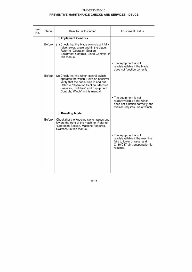
8/3/2019 TM 5-2430-200-10
http://slidepdf.com/reader/full/tm-5-2430-200-10 158/196
c. Implement Controls
Before (1) Check that the blade controls will fullyraise, lower, angle and tilt the blade.Refer to “Operation Section,Equipment Controls, Blade Controls” inthis manual.
• The equipment is notready/available if the bladedoes not function correctly.
Before (2) Check that the winch control switchoperates the winch. Have an obserververify that the cable runs in and out.Refer to “Operation Section, MachineFeatures, Switches” and “EquipmentControls, Winch” in this manual.
• The equipment is notready/available if the winchdoes not function correctly andmission requires use of winch.
d. Kneeling Mode
Before Check that the kneeling switch raises andlowers the front of the machine. Refer to“Operation Section, Machine Features,Switches” in this manual.
• The equipment is notready/available if the machinefails to lower or raise, andC130/C17 air transportation is
required.
PREVENTIVE MAINTENANCE CHECKS AND SERVICES—DEUCE
ItemNo.
Interval Item To Be Inspected Equipment Status
A–18
TM5-2430-200-10

8/3/2019 TM 5-2430-200-10
http://slidepdf.com/reader/full/tm-5-2430-200-10 159/196
e. Self-Deploy/Earthmoving Mode
Before (1) Check that the suspension system isactive when the machine is in theSELF-DEPLOY mode by having anobserver watch the suspensioncomponents while the machine ismoving slowly over rough terrain (ordriving over a solid object). Refer to“Operation Section, Machine Features,Self-Deploy/Earthmoving Mode
Switch” and “Machine Features,Suspension Manual Lockout Valves” inthis manual.
• The equipment is notready/available if the rearsuspension cylinder fails toextend and retract as the idlersroll over the rough terrain (or asolid object).
Before (2) Check that the suspension system is
locked when the machine is in theEARTHMOVING mode by having anobserver watch the suspensioncomponents while the machine isslowly moving FORWARD over roughterrain (or driving over a solid object).Refer to “Operation Section, MachineFeatures, Self-Deploy/EarthmovingMode Switch” and “Machine Features,Suspension Manual Lockout Valves” inthis manual.
• The equipment is notready/available if the rearsuspension cylinder continuesto extend and retract as theidlers roll over rough terrain (ora solid object.)
PREVENTIVE MAINTENANCE CHECKS AND SERVICES—DEUCE
ItemNo.
Interval Item To Be Inspected Equipment Status
A–19
TM5-2430-200-10

8/3/2019 TM 5-2430-200-10
http://slidepdf.com/reader/full/tm-5-2430-200-10 160/196
12 EXHAUST
Before Check for excessive black, blue, or whitesmoke, and unusual noise.
• The equipment is notready/available if the engineproduces excessive black,blue, or white smoke; or theengine is making an unusualnoise.
13 BATTERIES
Before Check batteries for corrosion, loose wires,and low water.
• The equipment is notready/available if the waterlevel is below the plates or ifthe vehicle will not start.
14 COMPONENTS OF END ITEM (COEI)
Before Check that all COEI are on the vehicleand are in working condition. Refer to“Appendix B, Components of End Item(COEI)” in this manual.
• The equipment is notready/available if COEI aremissing or broken.
15. BASIC ISSUE ITEMS (BII)
Before Check that all BII are on the vehicle andare in working condition. Refer to“Appendix C, Basic Issue Items (BII) List”in this manual.
•The equipment is notready/available if BII aremissing or broken.
PREVENTIVE MAINTENANCE CHECKS AND SERVICES—DEUCE
ItemNo.
Interval Item To Be Inspected Equipment Status
A–20
TM5-2430-200-10

8/3/2019 TM 5-2430-200-10
http://slidepdf.com/reader/full/tm-5-2430-200-10 161/196
16 INDICATORS, GAUGES,HORN AND LIGHTS
During Inspect the indicators during normaloperation.
• The equipment is notready/available if the engine oilpressure indicator, tension failindicator, low brake pressureindicator, or hydraulic oil
temperature indicatorilluminates.
During a. Indicators
Monitor recoil alert during normaloperations.
The equipment is notready/available if the recoil alertsounds. Refer to “OperationSection, Operating Techniques,Bulldozing,” in this manual.
b. Gauges
During Inspect all gauges for proper readings.
• The equipment is notready/available if any gauge isnot indicating normal operation.
Refer to “Operation Section,Monitoring Systems and CabFeatures, Gauges,” in thismanual.
PREVENTIVE MAINTENANCE CHECKS AND SERVICES—DEUCE
ItemNo.
Interval Item To Be Inspected Equipment Status
A–21
TM5-2430-200-10
Change 1

8/3/2019 TM 5-2430-200-10
http://slidepdf.com/reader/full/tm-5-2430-200-10 162/196
16A FUEL TANK
NOTE: Refer to “Operation SectionMachine Features, Fuel Tank Fill Cap” inthis manual.
After (1) Check for missing or damaged fuelcap.
• The equipment is notready/available if the fuel cap is
missing or damaged.
After (2) Check the fuel level and the fuel tankfor visible leaks. Fill the fuel tank if it islow.
• The equipment is notready/available if any leaks arefound.
After (3) Check the cleanliness of the fuel cap.Clean the fuel cap if it is dirty.
17 UNDERCARRIAGE
NOTE: For illustrations of the lubricationpoints, refer to “Maintenance Section,Lubrication Chart,” and “Every 50 ServiceHours or Weekly, Undercarriage,” in thismanual.
a. Lubricate
Weekly Lubricate the undercarriage greasefittings. There are 28 fittings to belubricated at this interval.
• The equipment is notready/available if grease doesnot flow out of the pin sealswhen grease is added to the
joint.
PREVENTIVE MAINTENANCE CHECKS AND SERVICES – DEUCE
ItemNo.
Interval Item To Be Inspected Equipment Status
A–21.00
TM5-2430-200-10
Change 1

8/3/2019 TM 5-2430-200-10
http://slidepdf.com/reader/full/tm-5-2430-200-10 163/196
b. Check Oil Level
Weekly Check oil level in sight gauges on insidemidrollers and rear idlers.
• The equipment is notready/available if oil is notvisible in the sight gauge, or atthe required level.
PREVENTIVE MAINTENANCE CHECKS AND SERVICES – DEUCE
ItemNo.
Interval Item To Be Inspected Equipment Status
A-21.01
TM5-2430-200-10
Change 1

8/3/2019 TM 5-2430-200-10
http://slidepdf.com/reader/full/tm-5-2430-200-10 164/196
18 BLADE
NOTE: For illustrations of the lubricationpoints, refer to “Maintenance Section,Lubrication Chart” and “Every 50 ServiceHours or Weekly, Blade” in this manual.
Weekly Lubricate the blade grease fittings. Thereare ten fittings.
• The equipment is not
ready/available if grease doesnot flow out of the pin sealswhen grease is added to the
joint.
19 PINTLE HOOK
NOTE: For illustrations of the lubricationpoints, refer to “Lubrication Chart” and“Maintenance Section, Every 50 ServiceHours or Weekly, Pintle Hook” in thismanual.
Weekly Lubricate the pintle hook grease fittings.There are three fittings.
20 WINCH
NOTE: For illustrations of the lubricationpoints, refer to “Maintenance Section,Lubrication Chart” and “Every 250 ServiceHours or 3 Months, Winch” in this manual.
Quarterly (1) Lubricate fairleads. There are fourfittings.
Quarterly (2) Lubricate the doubling block. There isone fitting.NOTE: The doubling block is normallystored in the BII box.
PREVENTIVE MAINTENANCE CHECKS AND SERVICES—DEUCE
ItemNo.
Interval Item To Be Inspected Equipment Status
A–22
TM5-2430-200-10

8/3/2019 TM 5-2430-200-10
http://slidepdf.com/reader/full/tm-5-2430-200-10 165/196
Quarterly (3) Check cable for fraying, kinking, andsigns of damage or rusting.
• The equipment is notready/available if the cable iskinked or frayed. For additionalinformation about checkingcables, refer to “FM-5-125,Rigging, Techniques,Procedures, and Applications.”
Quarterly (4) Check the doubling block hook forwear and damage.
• The equipment is notready/available if the hook isworn, cracked, or bent beyond10 degrees.
21 CAB
NOTE: For illustrations of the lubricationpoints, refer to “Maintenance Section,
Lubrication Chart” and “Every 250 ServiceHours or 3 Months” in this manual.
Quarterly Lubricate the cab pin grease fittings.There are a total of two fittings.
22 ENGINE COOLANT HEATER
Quarterly Operate the engine coolant heater if it isinstalled on the machine.
• The equipment is not
ready/available if the enginecoolant heater does notoperate correctly, andtemperatures below –32°C(–25°F) are expected.
PREVENTIVE MAINTENANCE CHECKS AND SERVICES – DEUCE
ItemNo.
Interval Item To Be Inspected Equipment Status
A–23
TM5-2430-200-10
Change 1

8/3/2019 TM 5-2430-200-10
http://slidepdf.com/reader/full/tm-5-2430-200-10 166/196
23 AIR CONDITIONER UNIT
NOTE: Refer to Periodic Maintenance and Special Operation , Deployable Universal Combat Earthmover (DEUCE), Operations Section , Machine Storage, Preparation ofAir Conditioner Unit for Seasonal Use.
Quarterly (1) Check operation of the air conditionercompressor. Run compressor for aminimum of 30 seconds.
24 CASTOR WHEEL ASSEMBLIES
Quarterly Lubricate fittings located on each castorwheel assembly. Rotate each wheelassembly and castor to check for freemovement.
• The equipment is notready/available if the machine isrequired to be air transportedand a castor wheel assembly ismissing or the wheels or castor’sstick, bind or do not turn freely.
PREVENTIVE MAINTENANCE CHECKS AND SERVICES – DEUCE
ItemNo.
Interval Item To Be Inspected Equipment Status
A–24
TM5-2430-200-10
Change 1

8/3/2019 TM 5-2430-200-10
http://slidepdf.com/reader/full/tm-5-2430-200-10 167/196
B-1
APPENDIX BComponents of End Item (COEI)
GENERAL
This listing is for information purposes only, and is not authority to requisition replacements. Theseitems are part of the DEUCE. As part of the end item, these items must be with the end itemwhenever it is issued or transferred between property accounts. Items of COEI are transferredbetween property accounts. Items of COEI are removed and separately packaged for transportationor shipment only when necessary. Illustrations are furnished to help you find and identify the items.
EXPLANATION OF COLUMNS
The following items are a description of the columns in the COEI table.
(1) Illust No. - This column gives the number of the item illustrated.(2) National Stock Number - This column identifies the stock number of the item to be used
for requisitioning purposes.(3) Description CAGEC and Part Number - This column identifies the Federal item name (in
all capital letters) followed by a minimum description when needed. The last line below thedescription is the commercial and Government Entity Code (CAGEC) (in parenthesis) andthe part number.
(4) U/M - This column indicates how the item is issued for the National Stock Number shown incolumn two.
(5) Qty Rqd - This column indicates the quantity required.
TM5-2430-200-10

8/3/2019 TM 5-2430-200-10
http://slidepdf.com/reader/full/tm-5-2430-200-10 168/196
COMPONENTS OF END ITEM
1 3940-01-473-5761 DOUBLER BLOCK, WINCH (PART NUMBER 146-2671,CAGEC 11083) EA 1
2 2910-00-646-9727 CYLINDER ASSEMBLY, ETHER (PART NUMBER 7N-0296,
CAGEC 11083) EA 13 5315-01-476-1388 PIN, KNEELING LOCK (PART NUMBER 144-7887, CAGEC 11083) EA 2
4 4320-01-476-1389 HAND PUMP, HYDRAULIC (PART NUMBER 156-3436,CAGEC 11083) EA 1
(FOR USE BY UNIT MAINTENANCE PERSONNEL ONLY)5 2590-01-476-1392 LEVER ASSEMBLY, HAND PUMP (PART NUMBER 144-7890
CAGEC 11083) EA 1
6 LINES GROUP, GAUGE (PART NUMBER 162-8243CAGEC 11083) EA 1
7 LINES GROUP, COUPLER (PART NUMBER 156-3437CAGEC 11083) EA 1
8 4720-01-476-1391 HOSE ASSEMBLY (PART NUMBER 169-3173, CAGEC 11083) EA 1
B-2
(4)U/M
(1)IllustNo.
(2)National Stock
Number
(5)QtyRqd
(3)Description
CAGEC and Part Number
TM5-2430-200-10
1 2 3
5
7
4
8
6
Change 1

8/3/2019 TM 5-2430-200-10
http://slidepdf.com/reader/full/tm-5-2430-200-10 169/196
APPENDIX CBasic Issue Items (BII) List
GENERAL
These essential items are required to place the DEUCE in operation, to operate it, and to doemergency repairs. Although shipped and packaged separately, BII must be with the DEUCE duringoperation and when it is transferred between property accounts. This list is your authority torequest/requisition them for replacement, based on authorization of the end item by the TOE/MTOE.Illustrations are furnished to help you find and identify the items.
EXPLANATION OF COLUMNS
The following items are a description of the columns in the BII table.
(1) Illust No. - This column gives the number of the item illustrated.(2) National Stock Number - This column identifies the stock number of the item to be used
for requisitioning purposes.(3) Description CAGEC and Part Number - This column identifies the Federal item name (in
all capital letters) followed by a minimum description when needed. The last line below thedescription is the commercial and Government Entity Code (CAGEC) (in parenthesis) andthe part number.
(4) U/M - This column indicates how the item is issued for the National Stock Number shown incolumn two.
(5) Qty Rqd - This column indicates the quantity required.
TM5-2430-200-10
C-1

8/3/2019 TM 5-2430-200-10
http://slidepdf.com/reader/full/tm-5-2430-200-10 170/196
BASIC ISSUE ITEMS (BII) LIST
1 TM5-2430-200-10 OPERATOR’S MANUAL EA 12 2540-00-670-2459 BAG, PAMPHLET (PART NUMBER 11676920, CAGEC 19207) EA 1
3 7510-00-281-6180 BINDER, 3-RING (PART NUMBER 0391M, CAGEC 88001) EA 14 5140-00-356-8471 BAG, TOOL, SATCHEL (PART NUMBER 7541507, CAGEC 19204) EA 15 9905-00-148-9546 WARNING TRIANGLE (PART NUMBER 11669000, CAGEC 19207) EA 1
C-2
(4)U/M
(1)IllustNo.
(2)National Stock
Number
(5)QtyRqd
(3)Description
CAGEC and Part Number
TM5-2430-200-10
1
2 3
4
Deployable Universal CombatEarthmover (DEUCE)
TM5-2430-200-10January 1999
Operator’s Manual
NSN: 2430-01-423-2819
PIN:7RR00001-Up
Approved forpublicrelease;distribution isunlimited.
Headquarters, Department of the Army
5
Change 1

8/3/2019 TM 5-2430-200-10
http://slidepdf.com/reader/full/tm-5-2430-200-10 171/196
BASIC ISSUE ITEMS (BII) LIST
6 5340-01-050-7059 PADLOCK SET, 5 KEYED ALIKE(PART NUMBER AA59486-1AB05S2, CAGEC 58536) SET 1
7 4210-00-775-0127 EXTINGUISHER, FIRE (WITH BRACKET)(PART NUMBER 7015266, CAGEC 19207) EA 1
8 4930-00-253-2478 GUN, GREASE (PART NUMBER 8F9866, CAGEC 11083) EA 1
9 4930-00-288-1511 ADAPTER, GREASE GUN, (PART NUMBER G6, CAGEC 0AYB6) EA 1
C-3
(4)U/M
(1)IllustNo.
(2)National Stock
Number
(5)QtyRqd
(3)Description
CAGEC and Part Number
TM5-2430-200-10
6
8
9
7
Change 1

8/3/2019 TM 5-2430-200-10
http://slidepdf.com/reader/full/tm-5-2430-200-10 172/196
BASIC ISSUE ITEMS (BII) LIST
10 5120-00-449-8083 ADJUSTABLE WRENCH, 10 INCH(PART NUMBER 1B7536, CAGEC 11083) EA 1
11 5120-00-227-7356 SCREWDRIVER, FLAT TIP,(PART NUMBER 88213, CAGEC 57068) EA 1
12 5120-00-234-8913 SCREWDRIVER, CROSS TIP,
(PART NUMBER 546-019-001, CAGEC 59211) EA 113 5120-00-223-7396 PLIERS, (PART NUMBER 276, CAGEC 93389) EA 1
14 5110-00-541-6730 CUTTER, CABLE, HAND OPERATED,(PART NUMBER C-12, CAGEC 65196) EA 1
15 5340-01-504-3223 CASTER ASSEMBLY, (PART NUMBER MPCU1031,CAGEC 1BEE8) EA 2
(4)U/M
(1)IllustNo.
(2)National Stock
Number
(5)QtyRqd
(3)Description
CAGEC and Part Number
TM5-2430-200-10
C-4
10 11 12
13
Change 1
1514

8/3/2019 TM 5-2430-200-10
http://slidepdf.com/reader/full/tm-5-2430-200-10 173/196
APPENDIX DAdditional Authorization List
GENERAL
This list identifies items that do not have to accompany the DEUCE and that do not have to beturned in with it. These items are authorized to you by CTA, MTOE, TDA, or JTA.
EXPLANATION OF COLUMNS
The following items are a description of the columns in the AAL table.
(1) Item No. - This column gives the number of the item.(2) National Stock Number - This column identifies the stock number of the item to be used
for requisitioning purposes.(3) Description CAGEC and Part Number - This column identifies the Federal item name (in
all capital letters) followed by a minimum description when needed. The last line below the
description is the commercial and Government Entity Code (CAGEC) (in parenthesis) andthe part number.
(4) U/M - This column indicates how the item is issued for the National Stock Number shown incolumn two.
(5) Qty Rqd - This column indicates the quantity required.
TM5-2430-200-10
D-1
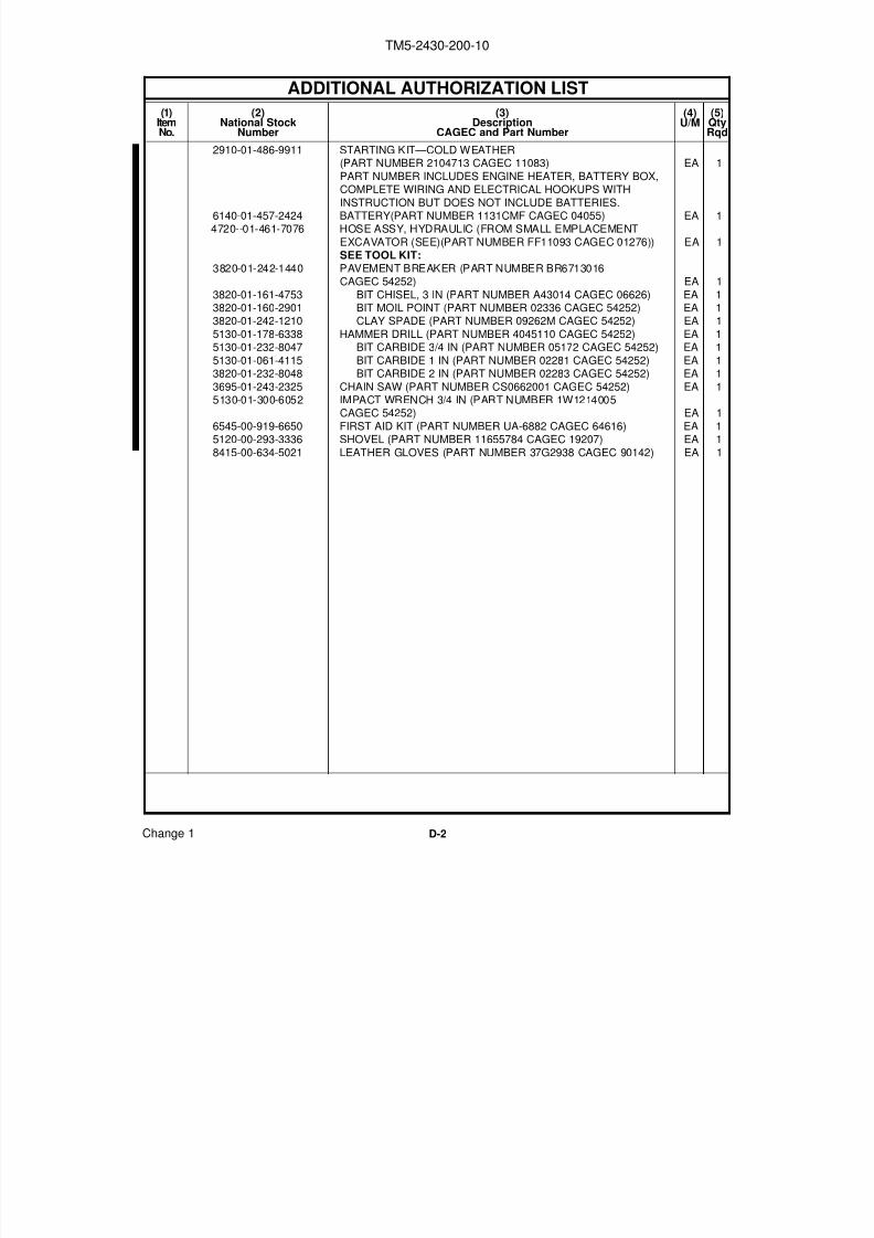
8/3/2019 TM 5-2430-200-10
http://slidepdf.com/reader/full/tm-5-2430-200-10 174/196
ADDITIONAL AUTHORIZATION LIST
2910-01-486-9911 STARTING KIT—COLD WEATHER
(PART NUMBER 2104713 CAGEC 11083) EA 1PART NUMBER INCLUDES ENGINE HEATER, BATTERY BOX,COMPLETE WIRING AND ELECTRICAL HOOKUPS WITH
INSTRUCTION BUT DOES NOT INCLUDE BATTERIES.6140-01-457-2424 BATTERY(PART NUMBER 1131CMF CAGEC 04055) EA 14720--01-461-7076 HOSE ASSY, HYDRAULIC (FROM SMALL EMPLACEMENT
EXCAVATOR (SEE)(PART NUMBER FF11093 CAGEC 01276)) EA 1SEE TOOL KIT:
3820-01-242-1440 PAVEMENT BREAKER (PART NUMBER BR6713016CAGEC 54252) EA 1
3820-01-161-4753 BIT CHISEL, 3 IN (PART NUMBER A43014 CAGEC 06626) EA 13820-01-160-2901 BIT MOIL POINT (PART NUMBER 02336 CAGEC 54252) EA 13820-01-242-1210 CLAY SPADE (PART NUMBER 09262M CAGEC 54252) EA 1
5130-01-178-6338 HAMMER DRILL (PART NUMBER 4045110 CAGEC 54252) EA 15130-01-232-8047 BIT CARBIDE 3/4 IN (PART NUMBER 05172 CAGEC 54252) EA 1
5130-01-061-4115 BIT CARBIDE 1 IN (PART NUMBER 02281 CAGEC 54252) EA 13820-01-232-8048 BIT CARBIDE 2 IN (PART NUMBER 02283 CAGEC 54252) EA 1
3695-01-243-2325 CHAIN SAW (PART NUMBER CS0662001 CAGEC 54252) EA 15130-01-300-6052 IMPACT WRENCH 3/4 IN (PART NUMBER 1W1214005
CAGEC 54252) EA 1
6545-00-919-6650 FIRST AID KIT (PART NUMBER UA-6882 CAGEC 64616) EA 15120-00-293-3336 SHOVEL (PART NUMBER 11655784 CAGEC 19207) EA 1
8415-00-634-5021 LEATHER GLOVES (PART NUMBER 37G2938 CAGEC 90142) EA 1
D-2
(4)U/M
(1)ItemNo.
(2)National Stock
Number
(5)QtyRqd
(3)Description
CAGEC and Part Number
TM5-2430-200-10
Change 1
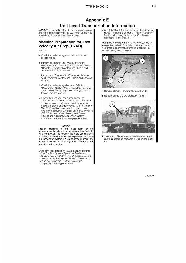
8/3/2019 TM 5-2430-200-10
http://slidepdf.com/reader/full/tm-5-2430-200-10 175/196
NOTE: This appendix is for information purposes onlyand is not authorization for the U.S. Army Operator to
maintain additional tools on the machine.
Machine Preparation for LowVelocity Air Drop (LVAD)Start By:
a. Check the undercarriage and belts for dirt andexcess debris.
b. Perform all “Before” and “Weekly” PreventiveMaintenance and Service (PMCS) checks. Refer to“Operator Preventive Maintenance Checks and
Services-DEUCE,” in this manual.
c. Perform unit “Quarterly” PMCS checks. Refer to“Unit Preventive Maintenance Checks and Services-DEUCE.
d. Check the undercarriage balance. Refer to“Maintenance Section, Maintenance Intervals, Every10 Service Hours or Daily, Undercarriage, Check Balance,” in this manual.
e. If more than one year has elapsed since themachines accumulators were charged, or if there isreason to suspect that the accumulators are not
properly charged, charge the accumulators. Refer toSpecifications Systems Operation, Testing and Adjusting, Deployable Universal Combat Earthmover,(DEUCE) Undercarriage, Steering and Brakes,“Testing and Adjusting, Suspension SystemProcedures, Accumulator Charging Procedure.”
NOTICEProper charging of the suspension systemaccumulators is critical to a successful Low VelocityAir Drop (LVAD). The nitrogen gas in the accumulatorsprovides the cushion necessary to prevent damage tothe suspension system. Failure to properly charge the
accumulators will result in significant damage to themachine during landing.
f. Check the suspension hydraulic pressure. Refer toSpecifications Systems Operation, Testing and Adjusting, Deployable Universal Combat Earthmover,Undercarriage, Steering and Brakes, “Testing and Adjusting, Suspension System Procedures,Suspension Charging Procedure.”
g. Check fuel level. The level indicator should read onehalf to three fourths of a tank. Refer to “Operation
Section, Monitoring Systems and Cab Features,Indicators,” in this manual.
NOTE: Park the machine on a flat, level surface toremove the top half of the cab. If the machine is notlevel, there is an increased chance of breaking awindow during the procedure.
1. Remove clamp (4) and muffler extension (2).
2. Remove clamp (3), and precleaner hood (1).
3. Store the muffler extension, precleaner assemblyand the associated hardware in BII compartment
(5).
5
1
2
43
Appendix E
Unit Level Transportation Information
E-1TM5-2430-200-10
Change 1
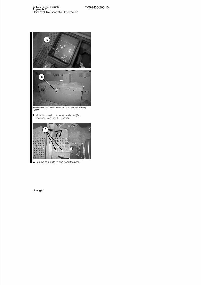
8/3/2019 TM 5-2430-200-10
http://slidepdf.com/reader/full/tm-5-2430-200-10 176/196
Second Main Disconnect Switch for Optional Arctic StartingSystem.
4. Move both main disconnect switches (6), if equipped, into the OFF position.
5. Remove four bolts (7) and tread the plate.
7
6
E-1.00 (E-1.01 Blank)Appendix EUnit Level Transportation Information
TM5-2430-200-10
6
Change 1

8/3/2019 TM 5-2430-200-10
http://slidepdf.com/reader/full/tm-5-2430-200-10 177/196

8/3/2019 TM 5-2430-200-10
http://slidepdf.com/reader/full/tm-5-2430-200-10 178/196
6. Remove four bolts (9) with washers, and riflebracket (8).
7. Remove one nut (10) with the washers, anddisconnect ground cable (11) from the ground stud.
8. Loosen one screw (13), and disconnectconnecter (12).
NOTE: Screw (13) is located in the center of connector (12).
9. Remove four bolts (14) with the washers from theleft front corner of the cab.
10. Remove four bolts (15) with the washers from theright front corner of the cab.
11. Remove four bolts (16) with the washers from theright rear corner of the cab.
16
15
14
12
13
10
11
9
8
E-2Appendix EUnit Level Transportation Information
TM5-2430-200-10
Change 1

8/3/2019 TM 5-2430-200-10
http://slidepdf.com/reader/full/tm-5-2430-200-10 179/196
12. Remove four bolts (17) with the washers from theleft rear corner of the cab.
13. Detach the insulation cover on the back of the cabat seam (18).
13. Attach a hoist to upper cab (19). The weight of theupper cab is approximately 431 kg (950 lb).
Improper lifting can allow the load to shift andcause injury or damage.
14. Lift the cab vertically for approximately25 mm (1 in) to allow the mounting pads in the
upper cab to clear guide pins (20) at the rear of the cab platform. Once the cab has cleared theguide pins, slowly move the cab forward until ithas cleared accelerator pedal (22), and thenremove it.
NOTE: Pay close attention when lifting the cab awayfrom the platform. Make sure that the cab does notdamage accelerator pedal (22), instrument console(21), or the back of the operator’s seat.
21
22
20
WARNING!
19
18
17
E-3Appendix E
Unit Level Transportation Information
TM5-2430-200-10

8/3/2019 TM 5-2430-200-10
http://slidepdf.com/reader/full/tm-5-2430-200-10 180/196
15. Verify that suspension manual lockout valve (23,on both sides of the machine) are turned fully
clockwise to the OPEN position.
NOTE: Rig the DEUCE in accordance with FM 10-521and TO 13C7-6-21
NOTE: The following procedure is for reconfiguringthe machine after it has been air dropped.
NOTE: Before the cab is replaced, the integrity of theseals between the cab and the platform should bechecked. Replace the seals if necessary. Reseal anyareas that may leak with 4C9613 RTV Silicone-Clear.
16. Lower the cab on guide pins (20) at the rear of thecab platform.
NOTE: Pay close attention when lowering the cabonto the platform. Make sure that the cab does notdamage accelerator pedal (22), instrument console(21), or the back of the operator’s seat.
17. Install four bolts (17) with the washers in the leftrear corner of the cab. Tighten the bolts to a
torque of 460 ± 60 N•m (340 ± 45 lb ft).
18. Install four bolts (16) with the washers in the rightrear corner of the cab. Tighten the bolts to atorque of 460 ± 60 N•m (340 ± 45 lb ft).
19. Install four bolts (15) with the washers in the rightfront corner of the cab. Tighten the bolts to atorque of 460 ± 60 N•m (340 ± 45 lb ft).
15
16
17
20
23
E-4Appendix EUnit Level Transportation Information
TM5-2430-200-10
Change 1

8/3/2019 TM 5-2430-200-10
http://slidepdf.com/reader/full/tm-5-2430-200-10 181/196
20. Install four bolts (14) with the washers in the leftfront corner of the cab. Tighten the bolts to a
torque of 460 ± 60 N•m (340 ± 45 lb ft).
21. Connect connector (12), and tighten screw (13) toa torque of 0.9 N•m (8 lb in).
22. Install four bolts (10) with the washers, and riflebracket (9).
23. Install four bolts (7) with the washers, and thetread plate.
24. Attach the insulation cover on the back of the cabat seam (18).
18
7
9
8
12
13
14
E-5Appendix E
Unit Level Transportation Information
TM5-2430-200-10

8/3/2019 TM 5-2430-200-10
http://slidepdf.com/reader/full/tm-5-2430-200-10 182/196
Second Main Disconnect Switch for Optional Arctic StartingSystem.
25. Move both main disconnect switches (6), if equipped, into the ON position.
26. Retrieve the muffler extension, precleanerassembly and the associated hardware in BIIcompartment (5).
27. Install precleaner hood (1) with clamp (3).
28. Install muffler extension (2) with clamp (4). Makesure to install muffler extension (2) with the raincap hinge facing towards the front of the machine,as shown.
1
2
43
5
6
E-6Appendix EUnit Level Transportation Information
TM5-2430-200-10
Change 1
6

8/3/2019 TM 5-2430-200-10
http://slidepdf.com/reader/full/tm-5-2430-200-10 183/196
Preparation for Special Shipping Width
The machine should be prepared for special shippingwidth when it is necessary to reduce the width of themachine to 2591 mm (102 in).
NOTE: The following procedure is for reducing theshipping width of the machine by collapsing the blade. There may be other steps required to fully prepare themachine for shipping. Refer to “Operation Section, Transportation Information” in the Operator’s Manual.
1. Drive the machine onto the transport vehicle, park the machine in position for shipping, and apply theparking brake.
NOTE: It is possible to perform this procedure whilethe machine is not on the transport trailer, and thendrive the machine onto the transport trailer after theblade has been collapsed. However, care must betaken not to operate the blade angle function while theblade is collapsed, to avoid damaging the anglecylinders.
2. Angle the blade fully in the desired direction, andput the blade in position 25 mm (1.0 in) off the deck of the transport vehicle.
NOTE: The blade must be off the deck of thetransport machine to allow manual positioning of theblade after the angle cylinders are disconnected.
3. Stop the engine. Refer to “Operation Section,Machine Parking, Engine Stopping,” in theOperator’s Manual.
4. Remove bolt (2), pin retainer (3), and pin (1) fromretracted angle cylinder (4) and extended anglecylinder (5). Put the pins, bolts and retainers in alocation where they will not be lost during transport.
NOTE: It may be necessary to drive pin (1) in the rightangle cylinder down in order to remove the pin.
5. Slide angle cylinders (4) and (5) with the spacers ouof single tree (7). Collect the spacers, and place
them in a location where they will not get lostduring transport.
6. Rotate blade (6) by hand until the blade stopsagainst the singletree.
7. Slowly move the blade control lever into the downposition to allow the blade to rest on the transportvehicle deck.
NOTE: It is not necessary to start the machine tolower the blade. The blade will lower under its ownweight when the blade control valve is moved intoLOWER. If the start switch is in the ON position, the
machine must be in EARTHMOVING mode to lowerthe blade.
8. Secure the blade in the fully angled position toensure that it does not move during transport.
9. Secure angle cylinders (4) and (5) to keep the rodeyes from moving during transport. Make sure thatthe chrome portion of the cylinders will not comeinto contact with any hard surfaces duringtransport.
NOTICE
Do not wrap metal chains or other metallic retainersaround the chrome portion of the angle cylindersDamage to the chrome surfaces will cause thecylinders to leak and allow dirt into the hydraulicsystem.
10. Cover the exposed chrome portion of the cylindersin a suitable material to protect the chrome fromdamage during shipment.
6 4
7
5
1
2
3
4
5
E-7Appendix E
Unit Level Transportation Information
TM5-2430-200-10

8/3/2019 TM 5-2430-200-10
http://slidepdf.com/reader/full/tm-5-2430-200-10 184/196
NOTE: The following steps are for returning the bladeto normal service after the blade has been prepared
for special shipping width.
11. Remove all of the tie-down fasteners andprotective coverings from the blade and the anglecylinders.
12. Start the engine. Refer to “Operation Section,Engine Starting” in the Operator’s Manual.
13. Raise the blade until it is approximately 25 mm (1in) above the transport vehicle deck.
14. Move rod eye (8), of extended angle cylinder (5)into position in singletree (7). Rotate the blade by
hand to achieve correct alignment between theholes in the singletree and the hole in the rod eye.
15. Install one spacer above and below the rod eye toremove the vertical gap between the rod eye andthe singletree.
16. Install pin (1), retainer (3), and bolt (2).
17. Lower the blade to the ground, and apply slightdownward pressure to the blade to keep it fromrotating.
NOTE: The machine must be in EARTHMOVINGmode to lower the blade when the start switch is inthe ON position.
18. Put rod eye (9) of retracted angle cylinder (4) intoposition in singletree (7).
19. Operate the blade angle function to extend orretract the rod eye of retracted angle cylinder (4)until the rod eye is aligned with the hole for the pinin singletree (7).
20. Install one spacer above and below the rod eye toremove the vertical gap between the rod eye andthe singletree.
21. Install pin (1), retainer (3) and bolt (2).
22. The blade is now ready for normal operation.
NOTE: Be sure grease the angle cylinder pins beforeusing the machine to do work.
1
2
34
9
1 2
3
7
8 5
E-8Appendix EUnit Level Transportation Information
TM5-2430-200-10

8/3/2019 TM 5-2430-200-10
http://slidepdf.com/reader/full/tm-5-2430-200-10 185/196
NOTE: For additional information about the PLGR, referto TM 11-5825-291-13, Operations and Maintenance
Manual, Satellite Signals Navigation Sets AN/PSN-11 and AN/PSN-11(V)1.
NOTE: This appendix is not authorization for the operatorto maintain additional tools or perform maintenancetasks.
1. Move the main disconnect switch to the OFF position.Refer to “Operation Section, Maintenance Features,Main Disconnect Switch.”
2. Remove plug (2) from the hole in the cab near antennamounting bracket (1).
3. Install the nonmetallic grommet in hole (2).
4. Use one 10-32 screw with a washer to install antenna(3) on antenna mounting bracket (1).
NOTE: The screw is installed through the bottom of mounting bracket (1).
5. From inside the cab, feed antenna wire (4) through thehole, and connect the end of the wire to antenna (3).
NOTE: Inside the cab, feed the end of antenna wire (4),which attaches to the navigation set, through the strapsalong the upper right side and down the right side of thecab. Use wire ties to secure the wire to the straps.
6. Use four 10-24 (16 mm [0.625 in] long) screws withtwo washers and one 10-24 nut per screw to install
PLGR mount (5) to the mounting bracket on the rightconsole.
7. Connect end (8) of the power cord to power strip (6),and end (7) to the navigation set.
NOTE: Power strip (6) is 24 volts. Route the power cable
through the same straps as the antenna cable. Secure
any excess power cable and antenna wire with wire ties.
7
8
6
5
43
1
1 2
Appendix F
PLGR Instructions
F-1TM5-2430-200-10

8/3/2019 TM 5-2430-200-10
http://slidepdf.com/reader/full/tm-5-2430-200-10 186/196
PLGR BILL OF MATERIAL
12
3
4 5
F-2
(4)U/M
(1)IllustNo.
(2)National Stock
Number
(5)QtyRqd
(3)Description
TM5-2430-200-10
1 5985-01-375-4660 ANTENNA, REMOTE AS-4333/V EA 12 6150-01-375-8661 CABLE ASSEMBLY, POWER (AN/PSN-11
EXTERNAL POWER CABLE EA 13 6150-01-375-8662 CABLE ASSEMBLY, SPECIAL (AS/PSN-11 TO REMOTE
ANTENNA CABLE EA 1
4 5825-01-374-6643 NAVIGATION SET, SATELLITE SIGNALS (AN/PSN-11[V]1) EA 15 5975-01-375-1302 MOUNT EA 1
- 5305-00-576-7521 10-32X3/8 SLOTTED PAN HEAD MACHINE SCREW(PART NUMBER MS35224-61) EA 1
- 5305-00-043-6733 10-24X5/8 SLOTTED PAN HEAD MACHINE SCREW(PART NUMBER MS35225-64) EA 4
- 5310-00-934-9758 10-24 NUT (PART NUMBER MS35649-202) EA 4- 5310-00-014-5850 WASHER, HOLE ID 0.214 TO 0.227 IN
(PART NUMBER MS27183-42) EA 9
- 5325-00-291-9366 GROMMET, NONMETALLIC (PART NUMBER MS35489-11) EA 1- 5975-00-111-3208 STRAP, TIE DOWN, ELECTRICAL COMPONENTS
(PART NUMBER MS3357-5-9) EA 10

8/3/2019 TM 5-2430-200-10
http://slidepdf.com/reader/full/tm-5-2430-200-10 187/196
DISTRIBUTION: To be distributed in accordance with the initial distributionrequirements for IDN: 256552, TM 5-2430-200-10
9920209

8/3/2019 TM 5-2430-200-10
http://slidepdf.com/reader/full/tm-5-2430-200-10 188/196

8/3/2019 TM 5-2430-200-10
http://slidepdf.com/reader/full/tm-5-2430-200-10 189/196
RECOMMENDED CHANGES TO PUBLICATIONSAND BLANK FORMS
For use of this form, see AR 25-30; the proponent agency is ODISC4.
Use Part II (reverse) for Repair Parts and
Special Tool Lists (RPSTL) and Supply
Catalogs/Supply Manuals (SC/SM).
DATE
Date you filled outthis form.
TO: (Forward to proponent of publication or form) (Include ZIP Code)
AMSTA-LC-LMPP / TECH PUBS, TACOM-RI1 Rock Island Arsenal
Rock Island, IL 61299-7630
FROM: (Activity and location) (Include ZIP Code)
Your mailing address
PART I – ALL PUBLICATIONS (EXCEPT RPSTL AND SC/SM) AND BLANK FORMS
PUBLICATION/FORM NUMBER DATE Title Deployable Universal Combat, Earthmover
TM 5-2430-200-10 01 Mar 0` (DEUCE)
ITEMNO.
PAGENO.
PARA-GRAPH
LINENO. *
FIGURENO.
TABLENO.
RECOMMENDED CHANGES AND REASON(Provide exact wording of recommended changes, if possible).
*Reference to line numbers within the paragraph or subparagraph.
TYPED NAME, GRADE OR TITLE
Your Name
TELEPHONE EXCHANGE/AUTOVON, PLUS EXTENSION Signature
Your Signature
DA FORM 2028, FEB 74 REPLACES DA FORM 2028, 1 DEC 68, WHICH WILL BE USED. USAPPC V3.00

8/3/2019 TM 5-2430-200-10
http://slidepdf.com/reader/full/tm-5-2430-200-10 190/196
TO: (Forward direct to addressee listed in publication)
AMSTA-LC-LMPP / TECH PUBS, TACOM-RI
1 Rock Island Arsenal
Rock Island, IL 61299-7630
FROM: (Activity and location) (Include ZIP Code)
Your address
DATE
Date you filled out this
form
PART II – REPAIR PARTS AND SPECIAL TOOL LISTS AND SUPPLY CATALOGS/SUPPLY MANUALS
PUBLICATION NUMBER DATE TITLE Deployable Universal
PAGENO.
COLMNO.
LINENO.
NATIONAL STOCKNUMBER
REFERENCENO.
FIGURENO.
ITEMNO.
TOTAL NO.OF MAJOR
ITEMSSUPPORTED
RECOMMENDED ACTION
PART III – REMARKS (Any general remarks or recommendations, or suggestions for improvement of publications and blankforms. Additional blank sheets may be used if more space is needed.)
TYPED NAME, GRADE OR TITLE
Your Name
TELEPHONE EXCHANGE/AUTOVON, PLUS EXTENSION SIGNATURE
Your Signature
USAPPC V3.00
SAMPLE
TM 5-2430-200-10 01 Mar 01 Combat Earthmover (DEUCE)

8/3/2019 TM 5-2430-200-10
http://slidepdf.com/reader/full/tm-5-2430-200-10 191/196
RECOMMENDED CHANGES TO PUBLICATIONS
AND BLANK FORMS
For use of this form, see AR 25-30; the proponent agency is ODISC4.
Use Part II (reverse) for Repair Parts and
Special Tool Lists (RPSTL) and Supply
Catalogs/Supply Manuals (SC/SM).
DATE
AMSTA-LC-LMPP / TECH PUBS, TACOM-RI1 Rock Island ArsenalRock Island, IL 61299-7630
FROM: (Activity and location) (Include ZIP Code)
PART I – ALL PUBLICATIONS (EXCEPT RPSTL AND SC/SM) AND BLANK FORMS
PUBLICATION/FORM NUMBER DATE TITLE Deployable Universal Combat
TM 5-2430-200-10 01 Mar 01 Earthmover (LDEUCE)
ITEMNO.
PAGENO.
PARA-GRAPH
LINENO. *
FIGURENO.
TABLENO.
RECOMMENDED CHANGES AND REASON(Provide exact wording of recommended changes, if possible).
*Reference to line numbers within the paragraph or subparagraph.
TYPED NAME, GRADE OR TITLE TELEPHONE EXCHANGE/AUTOVON, PLUSEXTENSION
SIGNATURE
DA FORM 2028, FEB 74 REPLACES DA FORM 2028, 1 DEC 68, WHICH WILL BE USED. USAPPC V3.00
TO: (Forward to proponent of publication or form)(Include ZIP Code)

8/3/2019 TM 5-2430-200-10
http://slidepdf.com/reader/full/tm-5-2430-200-10 192/196
TO: (Forward direct to addressee listed in publication)
AMSTA-LC-LMPP / TECH PUBS, TACOM-RI
1 Rock Island Arsenal
Rock Island, IL 61299-7630
FROM: (Activity and location) (Include ZIP Code) DATE
PART II – REPAIR PARTS AND SPECIAL TOOL LISTS AND SUPPLY CATALOGS/SUPPLY MANUALS
PUBLICATION NUMBER DATE TITLE Deployable Universal Combat
PAGE
NO.
COLM
NO.
LINE
NO.
NATIONAL STOCK
NUMBER
REFERENCE
NO.
FIGURE
NO.
ITEM
NO.
TOTAL NO.
OF MAJOR
ITEMS
SUPPORTED
RECOMMENDED ACTION
PART III – REMARKS (Any general remarks or recommendations, or suggestions for improvement of publications and blankforms. Additional blank sheets may be used if more space is needed.)
TYPED NAME, GRADE OR TITLE TELEPHONE EXCHANGE/AUTOVON, PLUS EXTENSION SIGNATURE
USAPPC V3.00
TM 5-2430-200-10 01 Mar 01 Earthmover (DEUCE)

8/3/2019 TM 5-2430-200-10
http://slidepdf.com/reader/full/tm-5-2430-200-10 193/196
RECOMMENDED CHANGES TO PUBLICATIONS
AND BLANK FORMS
For use of this form, see AR 25-30; the proponent agency is ODISC4.
Use Part II (reverse) for Repair Parts and
Special Tool Lists (RPSTL) and Supply
Catalogs/Supply Manuals (SC/SM).
DATE
TO: (Forward to proponent of publication or form) (Include ZIP Code)
AMSTA-LC-LMPP / TECH PUBS, TACOM-RI
1 Rock Island Arsenal
Rock Island, IL 61299-7630
FROM: (Activity and location) (Include ZIP Code)
PUBLICATION/FORM NUMBER DATE TITLE Deployable Universal Combat
TM 5-2430-200-10 01 Mar 01 Earthmover (DEUCE)
ITEMNO.
PAGENO.
PARA-GRAPH
LINENO. *
FIGURENO.
TABLENO.
RECOMMENDED CHANGES AND REASON(Provide exact wording of recommended changes, if possible).
*Reference to line numbers within the paragraph or subparagraph.
TYPED NAME, GRADE OR TITLE TELEPHONE EXCHANGE/AUTOVON, PLUS
EXTENSION
SIGNATURE
DA FORM 2028, FEB 74 REPLACES DA FORM 2028, 1 DEC 68, WHICH WILL BE USED. USAPPC V3.00

8/3/2019 TM 5-2430-200-10
http://slidepdf.com/reader/full/tm-5-2430-200-10 194/196
TO: (Forward direct to addressee listed in publication)
AMSTA-LC-LMPP / TECH PUBS, TACOM-RI1 Rock Island ArsenalRock Island, IL 61299-7630
FROM: (Activity and location) (Include ZIP Code) DATE
PART II – REPAIR PARTS AND SPECIAL TOOL LISTS AND SUPPLY CATALOGS/SUPPLY MANUALS
PUBLICATION NUMBER DATE TITLE Deployable Universal Combat
TM 5-2430-200-10 01 Mar 01 Eathmover (DEUCE)
PAGENO.
COLMNO.
LINENO.
NATIONAL STOCKNUMBER
REFERENCENO.
FIGURENO.
ITEMNO.
TOTAL NO.
OF MAJORITEMS
SUPPORTED
RECOMMENDED ACTION
PART III – REMARKS ( Any general remarks or recommendations, or suggestions for improvement of publications and blank forms. Additional blank sheets may be used if more space is needed.)
TYPED NAME, GRADE OR TITLE TELEPHONE EXCHANGE/AUTOVON, PLUS EXTENSION SIGNATURE
USAPPC V3.00

8/3/2019 TM 5-2430-200-10
http://slidepdf.com/reader/full/tm-5-2430-200-10 195/196
THE METRIC SYSTEM AND EQUIVALENTS
LINEAR MEASURE SQUARE MEASURE
1 Centimeter = 10 Millimeters = 0.01 Meters = 0.3937 Inches 1 Sq Centimeter = 100 Sq Millimeters = 0.155 Sq Inches1 Meter = 100 Centimeters = 1000 Millimeters = 39.37 Inches 1 Sq Meter = 10,000 Sq Centimeters = 10.76 Sq Feet1 Kilometer = 1000 Meters = 0.621 Miles 1 Sq Kilometer = 1,000, 000 Sq Meters = 0. 386 Sq Miles
WEIGHTS CUBIC MEASURE
1 Gram = 0.001 Kilograms = 1000 Milligrams = 0.035 Ounces 1 Cu Centimeter = 1000 Cu Millimeters = 0.06 Cu Inches1 Kilogram = 1000 Grams = 2.2 Lb 1 Cu Meter = 1,000,000 Cu Centimeters = 35.31 Cu Feet1 Metric Ton = 1000 Kilograms = 1 Megagram = 1.1 Short Tons
LIQUID MEASURE TEMPERATURE
1 Milliliter = 0.001 Liters = 0.0338 Fluid Ounces 5/9 (oF -- 32) = oC1 Liter = 1000 Milliliters = 33.82 Fluid Ounces 212o Fahrenheit is equivalent to 100o Celsius
90o Fahrenheit is equivalent to 32.2o Celsius32o Fahrenheit is equivalent to 0o Celsius
9/5 Co + 32) = Fo
APPROXIMATE CONVERSION FACTORS
TO CHANGE TO MULTIPLY BY
Inches Centimeters 2.540. . . . . . . . . . . . . . . . . . . . . . . . . . . . . . . . . . . . . .
Feet Meters 0.305. . . . . . . . . . . . . . . . . . . . . . . . . . . . . . . . . . . . . . . . . . . . Yards Meters 0.914. . . . . . . . . . . . . . . . . . . . . . . . . . . . . . . . . . . . . . . . . .Miles Kilometers 1.609. . . . . . . . . . . . . . . . . . . . . . . . . . . . . . . . . . . . . . . .Square Inches Square Centimeters 6.451. . . . . . . . . . . . . . . . . . . . . . . .Square Feet Square Meters 0.093. . . . . . . . . . . . . . . . . . . . . . . . . . . . . .Square Yards Square Meters 0.836. . . . . . . . . . . . . . . . . . . . . . . . . . . . .Square Miles Square Kilometers 2.590. . . . . . . . . . . . . . . . . . . . . . . . . . Acres Square Hectometers 0.405. . . . . . . . . . . . . . . . . . . . . . . . . . . . . .Cubic Feet Cubic Meters 0.028. . . . . . . . . . . . . . . . . . . . . . . . . . . . . . . . .Cubic Yards Cubic Meters 0.765. . . . . . . . . . . . . . . . . . . . . . . . . . . . . . . .Fluid Ounces Milliliters 29.573. . . . . . . . . . . . . . . . . . . . . . . . . . . . . . . . . .Pints Liters 0.473. . . . . . . . . . . . . . . . . . . . . . . . . . . . . . . . . . . . . . . . . . . .Quarts Liters 0.946. . . . . . . . . . . . . . . . . . . . . . . . . . . . . . . . . . . . . . . . . . .Gallons Liters 3.785. . . . . . . . . . . . . . . . . . . . . . . . . . . . . . . . . . . . . . . . . .Ounces Grams 28.349. . . . . . . . . . . . . . . . . . . . . . . . . . . . . . . . . . . . . . . .Pounds Kilograms 0.454. . . . . . . . . . . . . . . . . . . . . . . . . . . . . . . . . . . . . .Short Tons Metric Tons 0.907. . . . . . . . . . . . . . . . . . . . . . . . . . . . . . . . . .Pound--Feet Newton--Meters 1.356. . . . . . . . . . . . . . . . . . . . . . . . . . . . .Pounds per Square Inch Kilopascals 6.895. . . . . . . . . . . . . . . . . . . . . .Miles per Gallon Kilometers per Liter 0.425. . . . . . . . . . . . . . . . . . . . . .Miles per Hour Kilometers per Hour 1.609. . . . . . . . . . . . . . . . . . . . . . . .
TO CHANGE TO MULTIPLY BY
Centimeters Inches 0.394. . . . . . . . . . . . . . . . . . . . . . . . . . . . . . . . . . . . .Meters Feet 3.280. . . . . . . . . . . . . . . . . . . . . . . . . . . . . . . . . . . . . . . . . . .Meters Yards 1.094. . . . . . . . . . . . . . . . . . . . . . . . . . . . . . . . . . . . . . . . . .Kilometers Miles 0.621. . . . . . . . . . . . . . . . . . . . . . . . . . . . . . . . . . . . . . . .Square Centimeters Square Inches 0.155. . . . . . . . . . . . . . . . . . . . . . .Square Meters Square Feet 10.764. . . . . . . . . . . . . . . . . . . . . . . . . . . . .Square Meters Square Yards 1.196. . . . . . . . . . . . . . . . . . . . . . . . . . . . .Square Kilometers Square Miles 0.386. . . . . . . . . . . . . . . . . . . . . . . . . .Square Hectometers Acres 2.471. . . . . . . . . . . . . . . . . . . . . . . . . . . . . .Cubic Meters Cubic Feet 35.315. . . . . . . . . . . . . . . . . . . . . . . . . . . . . . . .Cubic Meters Cubic Yards 1.308. . . . . . . . . . . . . . . . . . . . . . . . . . . . . . . .
Milliliters Fluid Ounces 0.034. . . . . . . . . . . . . . . . . . . . . . . . . . . . . . . . . . .Liters Pints 2.113. . . . . . . . . . . . . . . . . . . . . . . . . . . . . . . . . . . . . . . . . . . . .Liters Quarts 1.057. . . . . . . . . . . . . . . . . . . . . . . . . . . . . . . . . . . . . . . . . . .Liters Gallons 0.264. . . . . . . . . . . . . . . . . . . . . . . . . . . . . . . . . . . . . . . . . . .Grams Ounces 0.035. . . . . . . . . . . . . . . . . . . . . . . . . . . . . . . . . . . . . . . . .Kilograms Pounds 2.205. . . . . . . . . . . . . . . . . . . . . . . . . . . . . . . . . . . . . . .Metric Tons Short Tons 1.102. . . . . . . . . . . . . . . . . . . . . . . . . . . . . . . . . .Newton--Meters Pound--Feet 0.738. . . . . . . . . . . . . . . . . . . . . . . . . . . . .Kilopascals Pounds per Square Inch 0.145. . . . . . . . . . . . . . . . . . . . . .Kilometers per Liter Miles per Gallon 2.354. . . . . . . . . . . . . . . . . . . . . .Kilometers per Hour Miles per Hour 0.621. . . . . . . . . . . . . . . . . . . . . . .

8/3/2019 TM 5-2430-200-10
http://slidepdf.com/reader/full/tm-5-2430-200-10 196/196