tm 11-2300-370-15-1 department of the army technical manual installation of radio … · tm...
TRANSCRIPT

TM 11-2300-370-15-1
DEPARTMENT OF THE ARMY TECHNICAL MANUAL
INSTALLATION OF
RADIO SET
AN/MRC-117
HEADQUARTERS, DEPARTMENT OF THE ARMY
MARCH 1968

WARNING
Extremely dangerous voltages exist in Radio Set AN/MRC-117, and at the antenna connections ofRadio Set AN/GRC-158. Serious injury or death may result from contact with the antenna and theantenna lead-in cable. Dangerous potentials may exist on the equipment even when it is turned off.Follow all precautions outlined in TB SIG 291 at all times before operating the equipment.
DON’T TAKE CHANCES
EXTREMELY DANGEROUS VOLTAGES EXIST IN THE FOLLOWING UNITS OF RADIO SET AN/GRC-158:
Antenna Coupler CU-1669/GRC..............................................12, 000 volts
Whip Antenna ..........................................................................12, 000 volts
Either Receiver-Transmitter, Radio RT-698/ARC-102 ............12, 000 volts

TM 11-2300-370-15-1
This manual contains information copyrighted belonging to Collins Radio Company.
TECHNICAL MANUAL HEADQUARTERS,DEPARTMENT OF THE ARMY
No. 11-2300-370-15-1 WASHINGTON, D.C., 21 March 1968
INSTALLATION OF RADIO SET AN/MRC-117
Paragraph PageSECTION I. INTRODUCTION
Scope ........................................................................................................ 1-1 2Indexes of publications.............................................................................. 1-2 2Forms and records .................................................................................... 1-3 2
II. DESCRIPTION AND DATATable of components ................................................................................ 2-1 3Items furnished.......................................................................................... 2-2 3Contract identification................................................................................ 2-3 3System application .................................................................................... 2-4 3Additional illustrations................................................................................ 2-5 3
III. INSTALLATION AND MODIFICATION KIT AN/MRC-117General ..................................................................................................... 3-1 6Installation kit ............................................................................................ 3-2 8Modification kit .......................................................................................... 3-3 11Unpacking ................................................................................................. 3-4 12Assembly instructions for control unit pedestal ......................................... 3-5 12Assembly instructions for main case mount.............................................. 3-6 13Vehicle modification and power cable installation..................................... 3-7 13Control cable installation ........................................................................... 3-8 14Installation of control unit pedestal............................................................ 3-9 15Installation of power supply mount.......................................................... 3-10 16Installation of main case mount .............................................................. 3-11 16Final installation procedures ................................................................... 3-12 17
APPENDIX REFERENCES............................................................................................... 39
1

TM 11-2300-370-15-1
SECTION I
INTRODUCTION
1-1. ScopeThis technical manual contains installation toinstructions for the various kits, pedestals, remounts,and hardware which are required in a vehicle so thatRadio Set AN/GRC-158 may be mounted in the vehicleas part of Radio Set AN/MRC-117. Included in thismanual are a list of all the contractor’s kits with partnumbers for each required items, unpacking instructions,instructions for modification of the vehicle, and allinstallation procedures that are necessary. The materialherein supplements that given in TM 11-5820-672-12and other applicable technical manuals listed in appendixA. Both official and unofficial (contractor’s) nomenclatureand part numbers are used throughout this manual.
1-2. Indexes of Publicationsana. DA Pam 310-4. Refer to the latest issue of DA
Pam 310-4 to determine whether there are new editions,changes, or additional publications pertaining to theequipment.
b. DA Pam. 310-7. Refer to DA Pam 310-7 todetermine whether there are modification work orders(MWO’s) pertaining to the equipment. DA Pam 310-7lists all authorized Department of the Army modificationwork orders, identifying the type, model, series, andfederal stock number of the item to be modified; thenumber, date, and classification of the MWO; thecategory of maintenance authorized to perform the
modification; and the man-hours required to apply themodification to each item.
1-3. Forms and Recordsa. Reports of Maintenance and Unsatisfactory
Equipment. Use equipment forms and records inaccordance with instructions in TM 38-750.
b. Report of Packaging and HandlingDeficiencies. Fill out and forward DD Form 6 (Report ofPackaging and Handling Deficiencies) as prescribed inAR 700-58 (Army), NAVSUP Publication 378 (Navy),AFR 71-4 (Air Force), and MCO P4610-5 (MarineCorps).
c. Discrepancy in Shipment Report (DIS-REP)(SF361). Fill out and forward Discrepancy in ShipmentReport (DISREP) (SF361) prescribed in AR 55-38(Army), NAVSUP Pub 459 (Navy), AFM 75-34 (AirForce), and MCO P4610.19 (Marine Corps).
d. Report of Equipment Manual Improvements.Report of errors, omissions, and recommendations forimproving this manual by the individual user isencouraged. Reports should be submitted on DA Form2028 (Recommended Changes to DA Publications) andforwarded direct to Commanding General, U.S. ArmyElectronics Command, ATTN: AMSEL-ME-NMP-CR,Fort Monmouth, N.J. 07703.
2

TM 11-2300-370-15-1
SECTION II
DESCRIPTION AND DATA
2-1. Table of ComponentsComponents required for equipment mounting are citedin the following paragraphs and tables:
Paragraph Table Pages Title2 1 3 through 6 Component Parts for
Installation Kit.3 2 6 and 7 Radio Set AN/MRC-
117 Modification Kit.
2-2. Items Furnished ta. The complete installation and modification kit
for Radio Set AN/MRC-117 is shown in figure 2.b. Views of the individual kits, pedestals, mounts,
and hardware are given in figures 3 through 23c. Cable Assembly, Special Purpose, Electrical
CX-10359/G (fig. 6) is not furnished with the installationand modification kits. This cable is part of Radio SetAN/GRC-158 and is described in TM 11-5820-672-12.
2-3. Contract Identificationma. Electronics and installation equipments
covered in this manual were purchased under ContractNo. DAABO-7-67-C-0439 and Order No. FR 28-043-I6-22750(E).
b. Vehicles were purchased under ContractNo. DAAE07-67-C 2771. Radio Set AN/GRC-158 isinstalled in Truck, Cargo Pickup, with 4-door cab, 7000GVW 4x4 (International Harvester). Throughout thismanual, the vehicle will be referred to as InternationalHarvester Crew, Cargo Travellette Model 1200 Acommercial truck, and the work track shall refer to thiscommercial vehicle.
2-4. System ApplicationFor siting, shelter requirements, equipmentinterconnection, and antenna installation, refer to TM 11-5820-672-12.
2-5. Additional IllustrationsIllustrations shown in appendix D, TM 11-5820-672-12,which will aid in following the installation instructions arelisted as follows:
a. Figure D-1, main case, outline and mountingdimensions.
b. Figure D-2, control panel, outline and mountingdimensions.
c. Figure D-3, power supply, outline and mountingdimensions.
3

TM 11-2300-370-15-1
SECTION III
INSTALLATION AND MODIFICATION KIT AN/MNRC-117
3-1. GENERAL
These instructions provide complete installation procedures for mounting Radio Set AN/GRC-158 in an InternationalHarvester Crew/Cargo Travellette Model 1200 A commercial truck. When AN/GRC-158 is installed, truck and radio setwill be designated Radio Set AN/MRC-117, figure 1. Figure 2 shows the parts of the kit as listed in tables 1 and 2 lessmounting hardware.
Figure 1. Diagram, Radio Set AN/mRC-117
4

TM 11-2300-370-15-1
Figure 2. Installation and Modification Kit AN/MRC-117
5

TM 11-2300-370-15-1
3-2. INSTALLATION KIT
Table 1 lists the component parts for installation kit, Radio Set AN/MRC-117.
Table 1. Component Parts for Installation Kit
ITEM FIGURE PART NUMBER NOMENCLATURE QTY
775-0373-001 Control unit pedestalconsisting of the following:
1 2, 4 775-0676-001 Plate, mounting 1
2 2, 3 775-0677-001 Frame, mounting 1
3 2, 3 775-0407-001 Angle support 2
4 2, 3 775-0411-002 Support, left 1
5 2, 3 775-0411-001 Support, right 1
6 2, 3 775-0415-001 Plate, brace 2
7 2, 4 775-0404-001 Plate, backup 2
8 2, 4 553-9882-004 Pin, locating 4
9 4 757-0495-010 3/’8-16 X 1-1, /4 hexhead bolt 4
10 4 757-0494-007 3, /8 locknut 4
11 3 757-0495-016 1l4’4-20 X 7/8 hexhead bolt 22
12 3 757-0494-005 1, ’4-20 locknut 22
13 3 553-6937-003 1/’4 flat washer 44
14 3 775-0670-001 Clamp, cable 2
15 3, 4 343-0802-000 10-32 X 5I/8 screw 4
16 3, 4 757-0494-004 10-32 locknut 4
775-0371-001 Main case mountconsisting of the following:
18 2, 5 775-0517-001 Frame, mounting 1
19 2, 5 775-0416-001 Support, frame mounting right 1
6

TM 11-2300-370-15-1Table 1. Component Parts for Installation Kit (Cont)
ITEM FIGURE PART NUMBER NOMENCLATURE QTY
20 2, 5 775-0410-001 Support, frame mounting left 1
21 2, 5 775-0408-001 Brace, frame mounting 2
22 2, 7 775-0409-001 Plate, brace, frame mounting 2
23 2, 7 775-0667-001 Plate, backup number 1 4
24 2, 7 775-0668-001 Plate, backup number 2 2
25 2, 7 775-0669-001 Plate, backup number 3 2
2G 2, 5 775-0665-001 Bracket, retaining 7
27 2, 5 775-0662-001 Bracket, angle, cable 1mounting
14 2, 5 775-0670-001 Clamp, cable 1
2, 8 2, 5 775-0511-001 Pin, locating 2
29 2, 7 775-0513-001 Plate, lock support
30 2, 7 77.5-0514-001 Block, lock support 4
31 2, 7 775-0417-001 Lock 4
32 7 757-0495-009 3/8-16 X 1 hexhead bolt 12
17 4, 7 553-6942-003 3/8 flat washer 40
10 5 757-0494-007 3/8-16 locknut 42
11 5 757-0495-016 ¼-20 X 7/8 hexhead bolt 16
13 5 553-6937-003 1/4 flat washer 16
12 5 757-0494-005 1/4 locknut 16
33 5 343-0803-000 10-32 X 3/4 screw 2
9 5 757-0495-010 3/8-16 X 1-1/4 hexhead bolt 28
35 7 553-6951-003 10 lockwasher 20
15 7 343-0802-000 10-32 X 5/8 screw 20
16 7 757-0494-004 10-32 locknut 10
7

TM 11-2300-370-15-1
Table 1. Component Parts for Installation Kit (Cont)
ITEM FIGURE PART NUMBER NOMENCLATURE QTY
36 7 541-6114-002 Spacer, sleeve 8
38 7 324-1529-000 3/8-24 X 1-1/14 hexsocket 8screw
39 7 310-0291-000 3/8 lockwasher 8
34 7 343-0809-000 10-32 x 1-1/2 screw 8
775-0375-001 Power supply mountconsisting of the following:
40 2, 22 775-0515-001 Frame, mounting 1
28 2, 22 775-0511-001 Pin, locating 2
29 2, 22 775-0513-001 Plate, lock; support 4
30 2, 22 775-0514-001 Block, lock support 4
31 2, 22 775-0417-001 Lock 4
42 2, 22 775-0516-001 Plate, backup 4
38 22 324-1-529-000 3/8-24 X 1-1/2 hexsocket 8screw
39 22 310-0291-000 3/8 lockwasher 8
9 22 757-0495-010 3/8-16 X 1-1/4 hexhead bolt 8
10 22 757-0494-007 3/8-16 locknut 10
17 22 553-6942-003 3/8 flat washer 8
35 22 553-6951-003 10 lockwasher 20
15 22 343-0802-000 10-32 X 5/8 screw 28
16 22 757-0494-004 10-32 locknut 8
36 22 541-6114-002 Spacer, sleeve 8
34 22 313-0809-000 10-32 x 1-1/2 screw 8
8

TM 11-2300-370-15-1
Table 1. Component Parts for Installation Kit (Cont)
ITEM FIGURE PART NUMBER NOMENCLATURE QTY
775-0369-001 Control cable setconsisting of the following:
43 2, 18 775-0370-001 Cable, control #1 1
44 2, 18 775-0371-001 Cable, control #2 1
45 2, 18 775-0372-001 Cable, control #3 1
14 2, 4 775-0670-001 Clamp, cable control set 2
46 2, 4 775-04114-001 Retainer, cable control set 4
16 4 757-0494-004 10-32 locknut 20
15 4 343-0802-000 10-32 X 5/8 screw 20
NOTE: Items 37 and 41 have been deleted.
3-3. MODIFICATION KIT
Table 2 lists the component parts for Radio Set AN/MRC-117 modification kit.
Table 1. Component Parts for Installation Kit (Cont)
ITEM FIGURE PART NUMBER NOMENCLATURE QTY
Modification kit, 24-volt powercable consisting of the following:
47 2, 12 775-0671-001 Strap, cable retainer 8
46 2, 12 546-7481-002 Clamp, power cable 2
49 2, 12 775-0664-001 Retainer, cable, power 2
50 2, 12 763-4045-001 Clamp, connector, strain relief 1
51 2, 12 763-4044-001 Plate, connector, strain relief 1
52 2, 12 775-0672-001 Bus bar 1
9

TM 11-2300-370-15-1
Table 2. Radio Set AN/MRC-117 Modification Kit (Cont)
ITEM FIGURE PART NUMBER NOMENCLATURE QTY
53 12 775-0687-001 Cover, access hole, battery box 2
54 12 757-0495-017 1/4-20 X 1-1/2 hexhead bolts 16
12 12 757-0494-005 1/"4-20 locknut 21
16 12 757-0494-001 10-32 locknut 12
15 12 343-0802-000 10-32 X 5/8 screw 10
55 12 342-0227-000 10-32 X 7/8 flat head screw 2
56 12 343-0370-000 1/4-20 X 1 screw (brass) 1
57 2, 12 775-0368-001 Cable, ground 1
58 2, 12 265-1173-002 Terminal block 1
59 12 304-0009-000 Lugs, solder 2
60 12 152-3973-000 Sleeving, shrink 2
61 2, 12 150-0173-000 Grommet 1
62 2, 12 357-4537-010 Connector MS 3106E-32-5S 1
3-4. UNPACKING
a. When packed for shipment, the parts of installation and modification kit Radio Set AN/MRC-117 w-ill be in one package.
b. Remove all mounting frame parts and check for damaged and/or missing parts.
3-5. ASSEMBLY INSTRUCTIONS FOR CONTROL UNIT PEDESTAL
Note
Leave all fastenings loose to allow movement in all joints to compensate for minor variations in truckdimensions.
10

TM 11-2300-370-15-1
a. Attach one brace plate, item 6, to front of left support, item 4, and right support, item 5, using items 11, 12, and 13 (figure 3).
b. Attach second brace plate, item 6, to rear of left and right supports, items 4 and 5, with items 11, 12, and 13(figure 3).
c. Attach the two angle supports, item 3, to the left and right supports, items 4 and 5, with items 11, 12, and 13(figure 3).
d. Attach mounting frame, item 2, to the top of the left and right supports with items 11, 12, and 13 (figure 3).
e. Attach mounting plate, item 1, to bottom of outer case of Control Unit C-719G6/GRC using four locating pins,item 8 (figure 4). Fasten tightly.
3-6. ASSEMBLY INSTRUCTIONS FOR MAIN CASE MOUNT
a. Attach left frame support, item 20, to mounting frame, item 18, using items 9, 10, and 17 (figure 5).
b. Attach right frame support, item 19, to mounting frame, item 18, using items 9, 17, and 10 (figure 5). Fastenitems 19 and 20 tightly to item 18 at this time.
c. Attach the seven retaining brackets, item 26, to the main case mount assembly with items 11, 12, and 13(figures 5 and 6). Fasten loosely.
d. Attach the angle bracket, item 27, to the left frame support with items 11, 12, and 13 (figures 5 and 6). Fastenloosely.
e. Attach mounting frame brace, item 21, to mounting frame, item 18, with items 9, 10, and 17 (figures 5 and 8).Fasten tightly.
3-7. VEHICLE MODIFICATION AND POWER CABLE INSTALLATION
Note
Disconnect battery cable at battery box. Carefully tag cable with correct polarity to ensure properreinstallation. Reversed polarity will result in damage to the alternator.
a. Cut a 1-3/4-inch-diameter hole in floor of truck cargo compartment. Locate this hole just forward of the batterybox, second full rib of cargo compartment floor counting from the right hand (passenger) side (figures 9 and 10).
b. Install grommet, item 61, in the I -3/’4-inch hole and cement in place using adhesive 3M EC 847 or equivalent(figure 22).
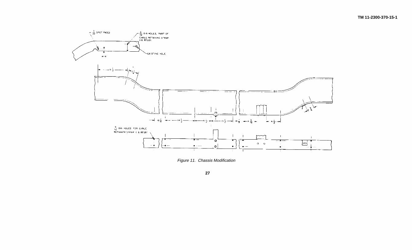
c. Drill seven sets of holes on the lower lip of the right-hand channel of truck frame and one set on the upper lip(figure 11).
11

TM 11-2300-370-15-1
d. In the engine compartment, locate the battery cable to the generator. Measure back from the terminal lug about12 inches and cut the cable. Install sleeving, item GO, and solder lugs, item 59, to the cut ends of the cable (figure12, detail A).
e. Locate an existing hole in the side wall of the engine compartment near where the cut was made in the cable(figure 13). Use this hole to position terminal block, item 58, and drill the other hole using the block as a template.Fasten terminal block, item 58, in place tightly with items 55 and 16 (figure 12). Attach bus bar, item 52, battery cable(existing) and ground cable, item 57, to terminal block, item 5.5, and fasten tightly (figures 12 and 14).
f. Drill a hole in the upper lip of truck frame just below the terminal block, item 58 (figures 11 and 14). Spot-facearound the hole, and attach the 1oose end of ground cable, item 57, to the truck frame with items 56; and 12 (figures12 and 14).
Note
Make sure metal is thoroughly clean to provide good ground connection.
g. Fasten power cable to battery post on voltage regulator and negative generator post. Route the cable to the rearof the truck by way of the right-hand channel of the truck frame. Fasten cable retainer straps, item 47, on the lowerlip of frame channel using items 54 and 12, holding the cable in position (figure 12). Fasten loosely.
h. Drill four holes in side wall of engine compartment using cable clamps, item 48, as templates (figures 12 and14). Fasten tightly with items 15 and 16.
i. Pass cable up through the 1-3/4-inch hole cut in floor of cargo compartment. Position cable retainer, item 49,around cable and drill four required holes. Fasten loosely with items 11, 12, and 13 (figures 10 and 22).
j. Attach connector, item 52, and strain relief plate and clamp, items 50 and 51, to cable (figures 10 and 12).
k. Fasten access hole covers, item 53, in place switch items 15 and 16 (figure 12).
l. Reconnect battery cable at battery box observing correct polarity.
3-8. CONTROL CABLE INSTALLATION
a. Cut three 1-3 h’4-inch-diameter holes in floor of cargo compartment on a front-to-rear axis (figure 9). Cut theholes just forward of where the power supply will be mounted (figure 19) on the second full rib of truck floor from theleft (driver) side.
b. Remove the rear seat. Cut three 1-3/4-inch-diameter holes in floor of crew compartment under the rear seatposition (figures 18 and 20). Use the front seat belt holddown bolts for a guide in positioning these holes (figures 15,18, and 20).
c. Set control cable clamp, item 14, in position on top of drive-shaft hump and drill two holes (figures 15 and 18).
d. Drill two holes in angle chassis brace on left (driver) side just forward of rear axle (figure 16).
12
TM 11-2300-370-15-1
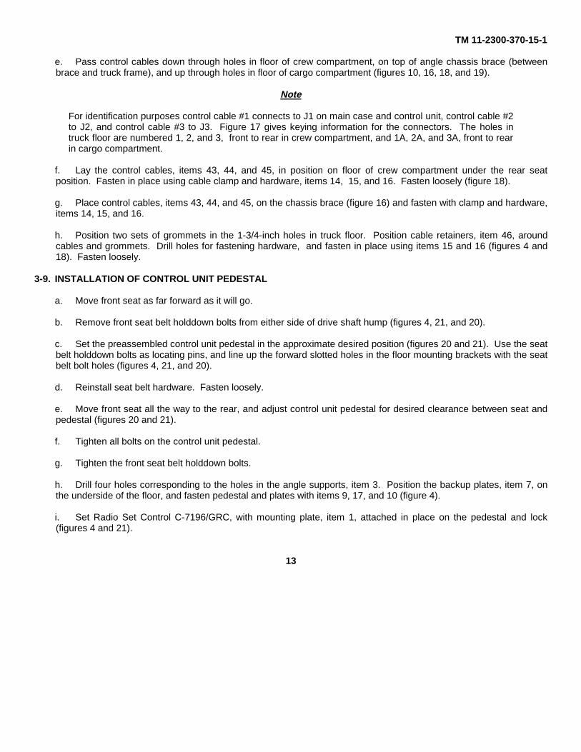
e. Pass control cables down through holes in floor of crew compartment, on top of angle chassis brace (betweenbrace and truck frame), and up through holes in floor of cargo compartment (figures 10, 16, 18, and 19).
Note
For identification purposes control cable #1 connects to J1 on main case and control unit, control cable #2to J2, and control cable #3 to J3. Figure 17 gives keying information for the connectors. The holes intruck floor are numbered 1, 2, and 3, front to rear in crew compartment, and 1A, 2A, and 3A, front to rearin cargo compartment.
f. Lay the control cables, items 43, 44, and 45, in position on floor of crew compartment under the rear seatposition. Fasten in place using cable clamp and hardware, items 14, 15, and 16. Fasten loosely (figure 18).
g. Place control cables, items 43, 44, and 45, on the chassis brace (figure 16) and fasten with clamp and hardware,items 14, 15, and 16.
h. Position two sets of grommets in the 1-3/4-inch holes in truck floor. Position cable retainers, item 46, aroundcables and grommets. Drill holes for fastening hardware, and fasten in place using items 15 and 16 (figures 4 and18). Fasten loosely.
3-9. INSTALLATION OF CONTROL UNIT PEDESTAL
a. Move front seat as far forward as it will go.
b. Remove front seat belt holddown bolts from either side of drive shaft hump (figures 4, 21, and 20).
c. Set the preassembled control unit pedestal in the approximate desired position (figures 20 and 21). Use the seatbelt holddown bolts as locating pins, and line up the forward slotted holes in the floor mounting brackets with the seatbelt bolt holes (figures 4, 21, and 20).
d. Reinstall seat belt hardware. Fasten loosely.
e. Move front seat all the way to the rear, and adjust control unit pedestal for desired clearance between seat andpedestal (figures 20 and 21).
f. Tighten all bolts on the control unit pedestal.
g. Tighten the front seat belt holddown bolts.
h. Drill four holes corresponding to the holes in the angle supports, item 3. Position the backup plates, item 7, onthe underside of the floor, and fasten pedestal and plates with items 9, 17, and 10 (figure 4).
i. Set Radio Set Control C-7196/GRC, with mounting plate, item 1, attached in place on the pedestal and lock(figures 4 and 21).
13

TM 11-2300-370-15-1
j. Connect control cables, item 43, , 14, and 45 to C-719?i. Dress neatly along pedestal support, and fasten with c,lamps and hardware, items 14, 15, and 16 (figure 21). Fasten loosely.
3-10. INSTALLATION OF POWER SUPPLY MOUNT
a. Set the mount, item 40, into the cargo compartment. Position it symmetrically on the first and third full ribs of thecargo, compartment floor, 14-1/2 inches back from the forward of the compartment (figures 9, 22, and 23).
b. Use the power supply mount, item 40, as a template, and drill 2 holes at each corner (figures 9 and 22).
c. Use hardware provided, items 9, 10, and 17, and fasten mount tightly in position (figure 22).
Note
Make sure that backup plates, item 42, are attached to the underside of the cargo compartment floor.
d. Install locating pins, item 28. Fasten loosely (figure 22).
3-11. INSTALLATION OF MAIN CASE MOUNT
Note
The cargo compartment is n)t symmetrical or uniform in all cases. For this reason measurements are notgiven.
a. Position the main case mount in the cargo compartment. Align the inside edges of the frame-support feetsymmetrically with the seams in the floor of the cargo compartment. Make sure the frame-support feet are NOTtouching the forward wall, side wall, and wheel sponson in the cargo compartment (figures 7, 19, and 23).
b. Set frame mounting brace plate, item 22, in position on wheel sponsons with the eight holes in the plate on top)(figures 7 and 8).
c. Carefully:, align brace plate, item 22, and frame mounting brace, item 21, so that two sets of holes in the braceplate show completely in the slotted holes of the mounting brace {figures 7 and 8).
Note
Either the first and third or second and fourth sets of holes, counting from out to in, should showcompletely. The brace plate, item 22, also must fit snugly against the side of the wheel sponson. If itdoes not, the main case mount will have to be repositioned carefully for the proper fit of the brace andbrace plate.
When brace and brace plate are aligned properly, drill four holes in top of each wheel sponson (figure 7).
14

TM 11-2300-370-15-1
d. Make sure the main case mount is not moved. Drill 12 holes in floor of cargo compartment using the holes in thesupport feet as drill guides (figure 7).
e. Remove main case mount. Check alignment of brace plate, and drill four holes in side of left wheel sponson.Fasten brace plate and backup plates, item 23, with items 9, 10, and 17 (figure 7).
f. Check the alignment of brace and brace plate on right wheel sponson, and drill the two upper holes in the side ofthe wheel sponson. Fasten brace plate and backup plates, item 23, with items 9, 10, and 17. From the tire side, drillthe bottom two holes and finish fastening brace plate and backup plate to truck.
g. Set the main case mount back in the truck and align it with the holes just drilled. Place backup plates, item 24,under the forward holes, and fasten with items 32, 10, and 17. Place backup plates, item 25, under the rear holes,and fasten with items 32, 10, and 17 (figure 7).
h. Attach control unit cables, items 43, 44, and 45, and Radio Set AN/GRC-158 Cable CX-10359/G to main casemount (figures 19 and 23).
Note
Cable clamps were installed during mount assembly (paragraph (6). Cable CX-10359/G is part of RadioSet AN/GRC-158 and is not supplied with the AN/MRC 117 installation and modification kit. CX-10359/Gconnects J5 on main case to J1 of power supply.
Install locating pins, item 28 (figure 5). Fasten loosely.
3-12. FINAL INSTALLATION PROCEDURES
a. Attach lock support block, item 30, to power supply case and main equipment case using items 38 and 39(figures 7 and 22). Fasten tightly.
b. Attach lock support plate, item 29, to lock support block, item 30, with items 15, 35, and 36 (figures 7 and 22).Fasten tightly.
c. Fasten the upper half of the lock, item 31, to the main equipment case and power supply case. Use items 34and 35 (figures 7 and 22).
d. Set all components of Radio Set AN/GRC-158 in place. Adjust locating pins, item 28, on main case mount andpower supply mount. When properly adjusted, remove main case and power supply and tighten pins. Set main caseand power supply back in position and lock all components of Radio Set AN/GRC-158 in place.
e. Connect all cables to the equipment.
f. Tighten all cable fastening hardware.
g. Check all fastenings for proper tightness.
15

TM 11-2300-370-15-1
Figure 3. Control Unit Pedestal, Exploded View
16

TM 11-2300-370-15-1
Figure 4. Control Unit Pedestal and Cable Retainer Installation
17

TM 11-2300-370-15-1
Figure 5. Main Case Mount Assembly, Exploded View
19

TM 11-2300-370-15-1
Figure 6. Main Case Mount, Cable Routing
21

TM 11-2300-370-15-1
Figure 7. Main Case Installation
22

TM 11-2300-370-15-1
Figure 8. Frame Mount Brace and Plate
23

TM 11-2300-370-15-1
Figure 9. Truck Box Modification, Dimensioning Layout
24

TM 11-2300-370-15-1
Figure 10. Cargo Compartment Cable, Modification and Installation
25
TM 11-2300-370-15-1
Figure 11. Chassis Modification
27

TM 11-2300-370-15-1
Figure 12. Power Cable Routing Hookup
28

TM 11-2300-370-15-1
Figure 13. Engine Compartment Cable Clamp Layout
29

TM 11-2300-370-15-1
Figure 14. Terminal Block and Cable Installation
30

TM 11-2300-370-15-1
Figure 15. Control Unit Pedestal -Modification, Dimensioning Layout
Figure 16. Control Cable Chassis Clamp Installation
31

TM 11-2300-370-15-1
Figure 17. Control Cable Connector, Keying Information
32

TM 11-2300-370-15-1
Figure 18. Crew Compartment Cable, Modification and Installation
33

TM 11-2300-370-15-1
Figure 19. CARGO COMPARTMENT INSTALLATION
34

TM 11-2300-370-15-1
Figure 20. Control Unit Pedestal Modification
3 5

TM 11-2300-370-15-1
Figure 21. Control Unit Pedestal Installation
36

TM 11-2300-370-15-1
Figure 22. Power Supply Mount Assembly and Installation
37

TM 11-2300-370-15-1
Figure 23. Main Case and Power Supply Installation
38

TM 11-2300-370-15-1
APPENDIX
REFERENCES
Following is a list of applicable references that should be available to the personnel concerned with Radio Sets AN/GRC-158 and AN/MRC-117:
DA Pam 310-4 Index of Technical Manuals, Technical Bulletins, Supply Manuals (types 7, 8, and 9),Supply Bulletins, and Lubrication Orders.
DA Pam 310-7 U.S. Army Equipment Index of Modification Work Orders.
SB 11-614 Caution Notice for Antenna Bases, Towers, and Other Mast Structures.
TB SIG 291 Safety Measures To Be Observed When Installing and Using Whip Antennas, Field TypeMasts, Towers, Antennas, and Metal Poles That are Used With Communication,Radar, and Direction Finder Equipment.
TB SIG 364 Field Instructions for Painting and Preserving Electronics Command Equipment.
TM 5-6115-271-15 Organizational, DS, GS, and Depot Maintenance Manual: Generator Set, GasolineEngine, 3 KW (less engine) 3 KW, AC, 400 cycle (Military Model HF 3.0 MD) FSN6115-075-1638 and FSN 6115-012-1993, 3 KW, AC, 60 cycle (Military Model SF 3.0MD) FSN 6115-075-1640 and FSN 6115-913-9290/3 KW, DC, 28V (Military ModelDC 3.0/MD/28V) FSN 6115-012-1997.
TM 9-2330-202-14P Operator, Organizational, and Field Maintenance Instructions, Repair Parts and SpecialTools List for Trailer, Cargo: 3/4-Ton, 2-Wheel, M101 (2320-738-9509) M101A1(2330-898-6779); Chassis; Trailer: 3/4-Ton, 2-Wheel M116 (2330-542-5987) andM116A1 (2330-898-6780).
TM 11-2651 Antenna Groups AN/GRA-5 and AN/GRA-12.
TM 11-4000 Troubleshooting and Repair of Radio Equipment.
TM 11-5820-467-15 Operator, Organizational, Field and Depot Maintenance Manual: Antenna GroupAN/GRA-50.
TM 11-5820-514-12 Organizational Maintenance Manual: Including Repair Parts and Special Tool Lists: RadioSet AN/MRC-95.
TM 11-5820-514-35 DS, GS, and Depot Maintenance Manual: Radio Set AN/MRC-95.
TM 11-5820-672-12 Operator and Organizational Maintenance Manual Including Repair Parts and SpecialTool Lists: Radio Sets AN/GRC-158 and AN/MRC-117.
TM 11-5820-696-15 Organizational, DS, GS, and Depot Maintenance Manual: Communications Facility,Mobilized AN/MRC-119 and Communications Facility, Jeep Mounted AN/MRC-120.
39
TM 11-2300-370-15-1
TM 11-5821-2,18-12 Organizational Maintenance Manual: Radio Set AN/ARC-102.
TM 11-5821-2,18-35 DS, GS, and Depot Maintenance Manual: Radio Set AN/ARC-102.
TM 11-5821-250-35P Direct and GS and Depot Maintenance Repair Parts and Special Tool Lists: Receiver-Transmitter, Radio RT-698/ARC-102.
TM 11-5821-271-15 Organizational, DS, GS, and Depot Maintenance Manual: Couplers, Antenna CU--1658/Aand CU-1669/GRC.
TM 11-5895-558-15 Organizational, DS, GS, and Depot Maintenance Manual: Radio Set AN/TRC-146.
TM 11-6625-622-12 Organizational Maintenance Manual Including Repair Parts and Special Tool Lists: TestHarness, Radio Set AN/URM-157.
TM 11-6625-682-15 Organizational, GS, and Depot Maintenance Manual: Including Repair Parts and SpecialTool Lists: Meter, Field Strength ME61/GRC.
TM 11-6625-1636-15 Organizational,-DS, GS, and Depot Maintenance Manual: Test Set, Antenna CouplerAN/ARM-109.
TM 38-750 Army Equipment Record Procedures.
40

TM 11-2300-370-15-1
By Order of the Secretary of the Army:
HAROLD K. JOHNSON,General, United States Army,
Official: Chief of Staff.KENNETH G. WICKHAM,Major General, United States Army,The Adjutant General.
Distribution:
Active Army:DCA (8) USASCS (40)USASA (2) USASTRATCOM (10)CNGB (1) USASTRATCOM-CONUS (10)CofSptS (1) Seventh USA (10)ACSC-E (2) Eighth USA (10)USACDCCEA (1) GENDEP(Europe) (5)USACDCCEA Ft Huachuca (1) Sig Sec GENDEP(Europe) (60)USAIMC (2) Sig Dep(Europe) (12)USAECOM (2) SigFLDMS(Europe) (2)USAREUR (10)
NG: State AG (3) units--none.USAR: None.For explanation of abbreviations used, see AR 320-50.
�U. S. GOVERNMENT PRINTING OFFICE : 1983 O - 381-647 (6531)
41


PIN: 016051-000

This fine document...
Was brought to you by me:
Liberated Manuals -- free army and government manuals
Why do I do it? I am tired of sleazy CD-ROM sellers, who take publicly available information, slap “watermarks” and other junk on it, and sell it. Those masters of search engine manipulation make sure that their sites that sell free information, come up first in search engines. They did not create it... They did not even scan it... Why should they get your money? Why are not letting you give those free manuals to your friends?
I am setting this document FREE. This document was made by the US Government and is NOT protected by Copyright. Feel free to share, republish, sell and so on.
I am not asking you for donations, fees or handouts. If you can, please provide a link to liberatedmanuals.com, so that free manuals come up first in search engines:
<A HREF=http://www.liberatedmanuals.com/>Free Military and Government Manuals</A>
– SincerelyIgor Chudovhttp://igor.chudov.com/
– Chicago Machinery Movers