title sheet mileage summary highway division n i t e l
TRANSCRIPT
NE 2
9 S
T
NE 4
6 S
T
NE 158 AVE
NE 142 AVE
NE 110 AVE
NE 108 AVE
NE 5
6 S
T
NE 3
3 C
T
NE 140 AVE
NE 142 AVE
NE 134 AVE
NE 166 AVE
NW 3
0 S
T
NW 4
4 S
T
NE 6 S
T
NE 118 AVE
NW 4
4 S
T
NW 110 AVE
NE 2
9 S
T
NE 4
2 S
T
NE 2
9 S
T
NE 126 AVE
NW 5
8 S
T
NW 158 AVE
NW 4
4 S
T
NW 142 AVE
NW 1
6 S
T
NE 118 AVE
NE 3
8 S
T
NE 102 AVE
NE 6 S
T
NW 3
7 S
T
NW 110 AVE
NE 166 AVE
NE 2
2 S
T
NE 158 AVE
NE 5
6 S
T
NE 142 AVE
NE 5
6 S
T
NE 3
8 S
T
NE 2
2 S
T
NW 166 AVE
NW 3
0 S
T
NW 1
6 S
T
NW 2 S
T
NE 150 AVENW 150 AVE
NE 134 AVE
NW 2 S
T
NW 134 AVE
NW 126 AVE NE 126 AVE
NE 150 AVE
NE 134 AVE
NE 4
6 S
T
340TH ST 340TH ST 340TH ST
NE F
RIS
K D
R
DR
NW LA
KE
NW S
HELD
AHL
DR
NE 2
4 C
T
NE 138 AVE
NE 4
6 S
TN
E 4
6 S
T
NE W
HITE O
AK D
R
NE 134 AVE
NW 98 AVE 44 S
T
NW
BOONE CO. STORY CO.
POP. 683
Four
Mile
Creek
RAILROAD
UNION PACIFIC
R-24W R-23W
CROCKER
OAK
WHITE
MADISON
LINCOLN
ELKHART
CROCKER
3456
7 89
10
15161718
19 20 2122
27282930
31 3233
34
123456
7 8 910 11 12
13
14151617
18
19 20 2122
24
252627282930
3132 33 34 35 36
12
13
25
2456
8
3456
8 9 10
1516
45582
POP.R56
R56
R38
F22 F22
R70
R70
319
POP.
432
POP.
3418
POP.
3
210 210 210
585TH A
VE
570TH A
VE
320TH ST
320TH ST
580TH A
VE
560TH A
VE
535TH A
VE
520TH A
VE
500TH A
VE
320TH
LN
340TH ST340TH ST340TH ST
NE 166TH AVE
AV
E
578TH
AV
E
505TH
AVE
NE 166TH
AVE
NE 166TH
AV
E
597TH
POLK CO.
Coon Creek
RAILROAD
UNION PACIFIC
R-24W R-23W
2526272829
3233 34 35 36
27282930
3133
3432 R70
1489
POP.
319
POP.
3317
POP.
827
POP.
NE 2
9 S
T
NE 4
6 S
T
NE 158 AVE
NE 142 AVE
NE 110 AVE
NE 108 AVE
NE 5
6 S
T
NE 3
3 C
T
NE 140 AVE
NE 142 AVE
NE 134 AVE
NE 166 AVE
NW 3
0 S
T
NW 4
4 S
T
NE 6 S
T
NE 118 AVE
NW 4
4 S
T
NW 110 AVE
NE 2
9 S
T
NE 4
2 S
T
NE 2
9 S
T
NE 126 AVE
NW 5
8 S
T
NW 158 AVE
NW 4
4 S
T
NW 142 AVE
NW 1
6 S
T
NE 118 AVE
NE 3
8 S
T
NE 102 AVE
NE 6 S
T
NW 3
7 S
T
NW 110 AVE
NE 166 AVE
NE 2
2 S
T
NE 158 AVE
NE 5
6 S
T
NE 142 AVE
NE 5
6 S
T
NE 3
8 S
T
NE 2
2 S
T
NW 166 AVE
NW 3
0 S
T
NW 1
6 S
T
NW 2 S
T
NE 150 AVENW 150 AVE
NE 134 AVE
NW 2 S
T
NW 134 AVE
NW 126 AVE NE 126 AVE
NE 150 AVE
NE 134 AVE
NE 4
6 S
T
340TH ST 340TH ST 340TH ST
NE F
RIS
K D
R
DR
NW LA
KE
NW S
HELD
AHL
DR
NE 2
4 C
T
NE 138 AVE
NE 4
6 S
TN
E 4
6 S
T
NE W
HITE O
AK D
R
NE 134 AVE
NW 98 AVE 44 S
T
NW
BOONE CO. STORY CO.
POP. 683
Four
Mile
Creek
RAILROAD
UNION PACIFIC
R-24W R-23W
CROCKER
OAK
WHITE
MADISON
LINCOLN
ELKHART
CROCKER
3456
7 89
10
15161718
19 20 2122
27282930
31 3233
34
123456
7 8 910 11 12
13
14151617
18
19 20 2122
24
252627282930
3132 33 34 35 36
12
13
25
2456
8
3456
8 9 10
1516
45582
POP.R56
R56
R38
F22 F22
R70
R70
319
POP.
432
POP.
3418
POP.
3
210 210 210
585TH A
VE
570TH A
VE
320TH ST
320TH ST
580TH A
VE
560TH A
VE
535TH A
VE
520TH A
VE
500TH A
VE
320TH
LN
340TH ST340TH ST340TH ST
NE 166TH AVE
AV
E
578TH
AV
E
505TH
AVE
NE 166TH
AVE
NE 166TH
AV
E
597TH
POLK CO.
Coon Creek
RAILROAD
UNION PACIFIC
R-24W R-23W
2526272829
3233 34 35 36
27282930
3133
3432 R70
1489
POP.
319
POP.
3317
POP.
827
POP.
NE 2
9 S
T
NE 4
6 S
T
NE 158 AVE
NE 142 AVE
NE 110 AVE
NE 108 AVE
NE 5
6 S
T
NE 3
3 C
T
NE 140 AVE
NE 142 AVE
NE 134 AVE
NE 166 AVE
NW 3
0 S
T
NW 4
4 S
T
NE 6 S
T
NE 118 AVE
NW 4
4 S
T
NW 110 AVE
NE 2
9 S
T
NE 4
2 S
T
NE 2
9 S
T
NE 126 AVE
NW 5
8 S
T
NW 158 AVE
NW 4
4 S
T
NW 142 AVE
NW 1
6 S
T
NE 118 AVE
NE 3
8 S
T
NE 102 AVE
NE 6 S
T
NW 3
7 S
T
NW 110 AVE
NE 166 AVE
NE 2
2 S
T
NE 158 AVE
NE 5
6 S
T
NE 142 AVE
NE 5
6 S
T
NE 3
8 S
T
NE 2
2 S
T
NW 166 AVE
NW 3
0 S
T
NW 1
6 S
T
NW 2 S
T
NE 150 AVENW 150 AVE
NE 134 AVE
NW 2 S
T
NW 134 AVE
NW 126 AVE NE 126 AVE
NE 150 AVE
NE 134 AVE
NE 4
6 S
T
340TH ST 340TH ST 340TH ST
NE F
RIS
K D
R
DR
NW LA
KE
NW S
HELD
AHL
DR
NE 2
4 C
T
NE 138 AVE
NE 4
6 S
TN
E 4
6 S
T
NE W
HITE O
AK D
R
NE 134 AVE
NW 98 AVE 44 S
T
NW
BOONE CO. STORY CO.
POP. 683
Four
Mile
Creek
RAILROAD
UNION PACIFIC
R-24W R-23W
CROCKER
OAK
WHITE
MADISON
LINCOLN
ELKHART
CROCKER
3456
7 89
10
15161718
19 20 2122
27282930
31 3233
34
123456
7 8 910 11 12
13
14151617
18
19 20 2122
24
252627282930
3132 33 34 35 36
12
13
25
2456
8
3456
8 9 10
1516
45582
POP.R56
R56
R38
F22 F22
R70
R70
319
POP.
432
POP.
3418
POP.
3
V8i_IDOTRoadJ:\2013_projects\113.0057\OVERLAY REFERENCE GUIDE\10-04-2017\77069100_A1.sht
DESIGN TEAM PROJECT NUMBER SHEET NUMBER COUNTYENGLISH
12:15:13 PM 5/3/2018
FILE NO.
REVISIONS
R.O.W. PROJECT NUMBER
PROJECT NUMBER
PROJECT IDENTIFICATION NUMBER
Lin. Ft.Div.
1
Location
MILEAGE SUMMARY
Miles
LE
TTIN
G
DA
TE
PC
C
OV
ER
LA
YS -
BO
ND
ED
AN
D
UN
BO
ND
ED
DateSignature
Printed or Typed Name
Pages or sheets covered by this seal:
DateSignature
Printed or Typed Name
Pages or sheets covered by this seal:
My license renewal date is
NAMESHEET NO. TYPE
INDEX OF SEALS
AADT
AADT
V.P.D.
V.P.D.
%
20__
20__
DESIGN TRAFFIC DATA
TRUCKS
A.1
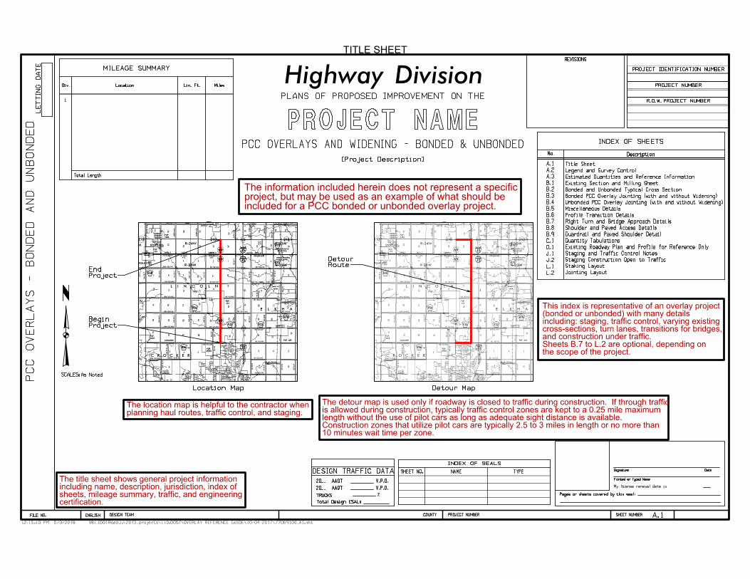
Highway DivisionPLANS OF PROPOSED IMPROVEMENT ON THE
PROJECT NAME
Location Map
INDEX OF SHEETSPCC OVERLAYS AND WIDENING - BONDED & UNBONDED
[Project Description]
TITLE SHEET
included for a PCC bonded or unbonded overlay project. project, but may be used as an example of what should beThe information included herein does not represent a specific
Detour Map
Total Design ESALs
L.2
L.1
J.2
J.1
D.1
C.1
B.9
B.8
B.7
B.6
B.5
B.4
B.3
B.2
B.1
A.3
A.2
A.1
SCALES: As Noted
RouteDetour
ProjectEnd
ProjectBegin
Jointing Layout
Staking Layout
Staging Construction Open to Traffic
Staging and Traffic Control Notes
Existing Roadway Plan and Profile for Reference Only
Quantity Tabulations
Guardrail and Paved Shoulder Detail
Shoulder and Paved Access Details
Right Turn and Bridge Approach Details
Profile Transition Details
Miscellaneous Details
Unbonded PCC Overlay Jointing (with and without Widening)
Bonded PCC Overlay Jointing (with and without Widening)
Bonded and Unbonded Typical Cross Section
Existing Section and Milling Sheet
Estimated Quantities and Reference Information
Legend and Survey Control
Title Sheet
Total Length
No. Description
planning haul routes, traffic control, and staging.The location map is helpful to the contractor when
certification. sheets, mileage summary, traffic, and engineeringincluding name, description, jurisdiction, index ofThe title sheet shows general project information
the scope of the project.Sheets B.7 to L.2 are optional, depending onand construction under traffic. cross-sections, turn lanes, transitions for bridges,including: staging, traffic control, varying existing(bonded or unbonded) with many detailsThis index is representative of an overlay project
10 minutes wait time per zone.Construction zones that utilize pilot cars are typically 2.5 to 3 miles in length or no more thanlength without the use of pilot cars as long as adequate sight distance is available.is allowed during construction, typically traffic control zones are kept to a 0.25 mile maximum The detour map is used only if roadway is closed to traffic during construction. If through traffic
69
69
6969
69
69
69
69
69
35
35
3535
35
35
35
35
35
V8i_IDOTRoad12:19:22 PM J:\2013_projects\113.0057\OVERLAY REFERENCE GUIDE\10-04-2017\77069100_A2-A3.sht
DESIGN TEAM PROJECT NUMBER SHEET NUMBER COUNTYENGLISH IOWA DOT
V8i_IDOTRoad12:19:22 PM J:\2013_projects\113.0057\OVERLAY REFERENCE GUIDE\10-04-2017\77069100_A2-A3.sht
DESIGN TEAM PROJECT NUMBER SHEET NUMBER COUNTYENGLISH IOWA DOT
5/3/2018
A.2
SECTION CORNER INFORMATION
5/8 RE-ROD
38.65°
71.26°
|
|
5/8 RE-ROD
FLUSH
FD. C.M.CONC. ISLAND
BK OF CURB
FD. MAG NAIL
68.18°
|
|
60.14'
71.41'
89.72'34.92'
36.97'
41.13'
70.43'
81.14'COR. PO.
FACE OF
COR. PO.
FACE OF
90.12'
FLUSH
FD. C.M.
FLUSH
FD. C.M.
FLUSH
RE-ROD
SET 5/8"
CROSS-TIED
CORNER IS
N = 7,556,329.479 E = 18,531,682.296
PINT NO 8000 FOUND MAG NAIL
IS P.I. 163+58.50 = P.I. STA. 163+58.5 AB
SE COR. SEC. 35-81-24
N = 7,558,967.255 E = 18,531,695.207
PINT NO 8001 FOUND I.D.O.T. ALUM. MON
IS P.I. 189+96.31 = P.I. STA. 189+98.0 AB
E 1/4 COR. SEC. 35-81-24UTILITY LEGENDSURVEY SYMBOLS
NAME
AS-BUILT VERTICAL PROFILE
LOCATION STATION FORWARD GRADE ELEVATION CURVE LENGTH
190
Match
Line
Sta. 193
+00
Distant - 2634.3825
N 0° 26' 32.82" E
E=18531695.2070
N=7558967.2550
PI Sta 189+96.31
165
170
175
180
185
Distant - 2637.8076
N 0° 16' 49.59" E
E=18531682.2960N=75563279.4790POT Sta 163+58.50
NORTHING EASTING DESCRIPTION
EXISTING REFERENCE POINTS AND BENCHMARKS
POINT STATION OFFSET ELEVATION
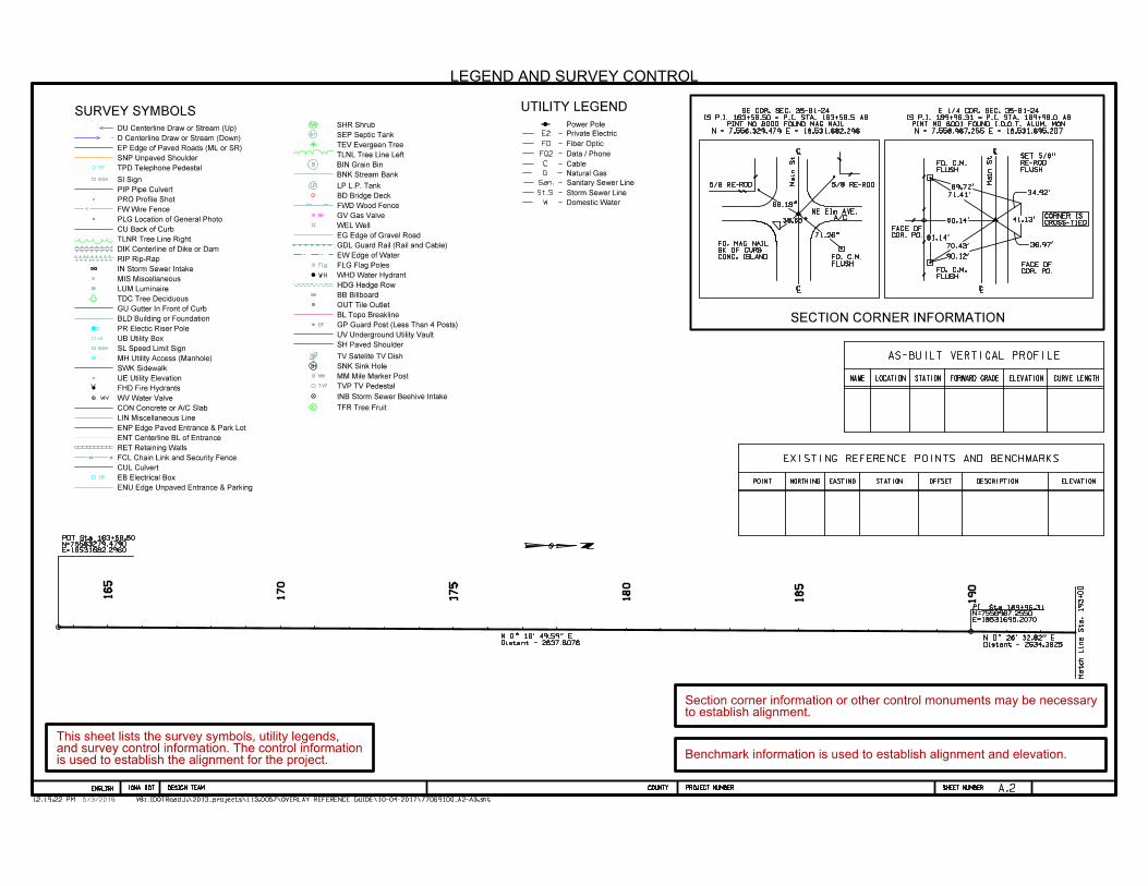
LEGEND AND SURVEY CONTROL
Benchmark information is used to establish alignment and elevation.
to establish alignment. Section corner information or other control monuments may be necessary
A/CNE EIm AVE.
Main
St
Main
St
DU Centerline Draw or Stream (Up)
D Centerline Draw or Stream (Down)
EP Edge of Paved Roads (ML or SR)
SNP Unpaved Shoulder
TPD Telephone Pedestal
SI Sign
PIP Pipe Culvert
PRO Profile Shot
FW Wire Fence
PLG Location of General Photo
CU Back of Curb
TLNR Tree Line Right
DIK Centerline of Dike or Dam
RIP Rip-Rap
IN Storm Sewer Intake
MIS Miscellaneous
LUM Luminaire
TDC Tree Deciduous
GU Gutter In Front of Curb
BLD Building or Foundation
PR Electic Riser Pole
UB Utility Box
SL Speed Limit Sign
MH Utility Access (Manhole)
SWK Sidewalk
UE Utility Elevation
FHD Fire Hydrants
WV Water Valve
CON Concrete or A/C Slab
LIN Miscellaneous Line
ENP Edge Paved Entrance & Park Lot
ENT Centerline BL of Entrance
RET Retaining Walls
FCL Chain Link and Security Fence
CUL Culvert
EB Electrical Box
ENU Edge Unpaved Entrance & Parking
SHR Shrub
SEP Septic Tank
TEV Evergeen Tree
TLNL Tree Line Left
BIN Grain Bin
BNK Stream Bank
LP L.P. Tank
BD Bridge Deck
FWD Wood Fence
GV Gas Valve
WEL Well
EG Edge of Gravel Road
GDL Guard Rail (Rail and Cable)
EW Edge of Water
FLG Flag Poles
WHD Water Hydrant
HDG Hedge Row
BB Billboard
OUT Tile Outlet
BL Topo Breakline
GP Guard Post (Less Than 4 Posts)
UV Underground Utility Vault
SH Paved Shoulder
TV Satelite TV Dish
SNK Sink Hole
MM Mile Marker Post
TVP TV Pedestal
INB Storm Sewer Beehive Intake
TFR Tree Fruit
Power Pole
Data / Phone
Private Electric
Cable
Natural Gas
Sanitary Sewer Line
Storm Sewer Line
Domestic Water
Fiber Optic
LP
GV
Flg
WH
BB
GP
SH
MM
TVP
F
TP
SIGN
UB
SIGN
WV
EB
SB
ST
B C
is used to establish the alignment for the project. and survey control information. The control informationThis sheet lists the survey symbols, utility legends,

V8i_IDOTRoad12:21:54 PM J:\2013_projects\113.0057\OVERLAY REFERENCE GUIDE\10-04-2017\77069100_A2-A3.sht
DESIGN TEAM PROJECT NUMBER SHEET NUMBER COUNTYENGLISH IOWA DOT
V8i_IDOTRoad12:21:54 PM J:\2013_projects\113.0057\OVERLAY REFERENCE GUIDE\10-04-2017\77069100_A2-A3.sht
DESIGN TEAM PROJECT NUMBER SHEET NUMBER COUNTYENGLISH IOWA DOT
5/3/2018
A.3
ESTIMATED PROJECT QUANTITIES
ITEM NO. ITEM UNIT
Division 1 Division 2
1
2
CYEMBANKMENT-IN-PLACE
3
4
CYTOPSOIL, FURNISH AND SPREAD
5
CYTOPSOIL, STRIP, SALVAGE AND SPREAD
6
7
TON
8
SY
9
PAVED SHOULDER, HOT MIX ASPHALT MIXTURE, 6 IN.
10
SHOULDER CONSTRUCTION, EARTH
11
12
PATCHES, FULL-DEPTH REPAIR
13
PATCHES BY COUNT (REPAIR)
14
15
SY
16
SY
17
18
19
20
21
GALBINDER BITUMEN, CRS-2
CY
SY
TON
22
23
24
25
26
27
28
29
LFSUBDRAIN, LONGITUDINAL, (SHOULDER) 4 IN. DIA.
30
EACH
31
LFREMOVAL OF STEEL BEAM GUARDRAIL
32
LFSTEEL BEAM GUARDRAIL
SYREMOVAL OF PAVEMENT
EACHSAFETY CLOSURE
EACHFIELD OFFICE
LSCONSTRUCTION SURVEY
STAPAINTED PAVEMENT MARKING, WATERBORNE OR SOLVENT-BASED
STAPAVEMENT MARKINGS REMOVED
LSTRAFFIC CONTROL
EACHFLAGGERS
EACHPILOT CARS
LSMOBILIZATION
EACH
GRANULAR SHOULDERS
PAVEMENT MILLING
SEPARATION LAYER HMA
AGGREGATE, COVER - SAND TON
SEPARATION LAYER - GEOTEXTILE
BRIDGE APPROACH
ESTIMATE REFERENCE INFORMATION
ITEM
NO.DESCRIPTION
NO.
1
2
3
4
Quatity based on right turn lane work area.
STA
SY
EACH
SY
SY
Material used for this bid item shall be obtained by the contractor and free of debris. No payment for overhaul will be allowed.
Item includes 579 cu. yds for the culvert repairs, 988 cu. yds. for the guardrail grading, and 277 cu. yds. for the right turn lane.
for shoulder irregularities.
Item includes 1500 tons for shoulders on sheet B.8, 807 tons for the right turn lanes, refer to sheet B.7, Quantity increased 10%
2
13
1
1
1,721.0
680
363.0
6,902.0
1,423.5
10.20
16.0
58,659.0
198.9
1.0
19.2
16,954.0
87,180.0
26.0
27,783.0
122
825.0
750
12,725.7
0.74
1,254.85
1.70
0.74
0.74
ESTIMATED QUANTITIES
70,101.00
70,101.00
0
4
6
46
123.0
111.0
1,690.0
5.10
32.0
25,292.0
0.3
6.4
7,283.0
37,450.0
22.0
9,875.0
404.0
0.26
494.44
0.26
0.26
10.0
20.0
TOTAL
ESTIMATE REFERENCE INFORMATION
DESCRIPTIONITEM
NO.
5
6
7
8
Meet the following requirements for profile milling:
9
Item includes 1255.5 sq. yds. for shoulders as per sheet B.8
Item includes 12.9 stations for the right turn lanes, refer to Typicals on sheet B.8.
Refer to Tabulation on sheet C.1.
Refer to Typical on sheet B.7.
Quantity increase 10% for irregulatites. Refer to Typicals on sheet B.2.
Refer to Tabulation on sheet B.9.
10
11
12
13
14
16
18
19
15
17
20
21
22
23
24
25
26
27
28
29
30
31
The item quantity is for 2 applications and is based on 128 sq. yds. at a rate of 10 pounds per square yard per application.
Place on existing PCC patches for unbonded ovrlay.
Refer to Tabulation on sheet C.1. The concractor to dispose of removed pavement as per the standard Specifications.
Refer to Tabulation on sheet C.1.
Refer to the Traffic Control Plan, Tabulation sheet C.1.
Measurement shall be the quantity shown in the contract documents. The basis of payment will be as indicated in specifications.
overlays on asphalt or composite pavement.
Profile milling will be required on this project, refer to Typical on sheet B.1 for locations and details. For unbonded or bonded
at an elevation corresponding to the approved profile grade and cross slope with a tolerance of 0 to -0.5 foot.
1. Pavement milling equipment shall be equipped with automatic horizontal and vertical controls capable of milling existing pavement
the requirements of the Standard Specifcations.
surface in areas that the mill did not initially touch due to the profile. Profile milling and profile design will consist of
2. The contractor will achieve a milled surface for 100% of the pavement surface. The contractor is required to scuff the pavement
1
6
19
1
1
1
70,101.00
70,101.00
1,844.0
680
474.0
8,592.0
1,423.5
48.0
83,951.0
198.9
1.3
25.6
24.237.0
124,630.0
48.0
37,658.0
168
825.0
750
13,129.7
1,749.29
1.70
1
20.0
10.0
15.30
32
Specifications.
roadway and design a profile grade as stated in the Standard
provided and that he/she will be required to cross section the
The contractor to note that a profile grade is not being
expense with no cost to the Owner.
the carelessness of the contractor, will be replaced at their
all times. Any damage to these tile lines or outlets due to
The existing longitudinal subdrains shall remain functional at
ESTIMATED QUANTITIES AND REFERENCE INFORMATION
This item does NOT include existing monument or centerline point preservation work which was done previously by others.
disposed of by the contractor as per the Specifications.Refer to Tabulation on sheet C.1. Approximately 2734 cu. yds. of trench material from the subdrain installation shall be
MOBILIZATION, EROSION CONTROL
For example, Division 1 is funded separately than Division 2 on this sample project.Projects are sometimes separated into divisions to track quantities and payment.
on the specifics of the project.Some items may be eliminated based
Refer to Tabulation on sheet C.1.
Apply on aggregate sand cover over existing PCC patches after milling (for unbonded overlay.)The item quantity is for 2 applications and is based on 128 sq. yds at a rate of 0.10 gallons per square yard per application.
Refer to Typicals on sheets B.2, B.3 and the Specifications.
PCC unbonded overlay over concrete.*Choose a separation layer type for
PORTLAND CEMENT CONCRETE OVERLAY, FURNISH ONLY
PORTLAND CEMENT CONCRETE OVERLAY, PLACEMENT ONLY
SUBDRAIN OUTLET
EMBANKMENT-IN-PLACE
TOPSOIL, FURNISH AND SPREAD
TOPSOIL, STRIP, SALVAGE AND SPREAD
GRANULAR SHOULDERS
PAVED SHOULDER, HOT MIX ASPHALT MIXTURE, 6 IN.
SHOULDER CONSTRUCTION, EARTH
PATCHES, FULL-DEPTH REPAIR
PATCHES BY COUNT (REPAIR)
PAVEMENT MILLING
BRIDGE APPROACH
SEPARATION LAYER HMA
SEPARATION LAYER - GEOTEXTILE
AGGREGATE, COVER - SAND - NOTE: CONSIDER GEOTEXTILE IN LIEU OF SAND
BINDER BITUMEN, CRS-2 - NOTE: CONSIDER GEOTEXTILE IN LIEU OF BINDER
PORTLAND CEMENT CONCRETE OVERLAY, FURNISH ONLY
PORTLAND CEMENT CONCRETE OVERLAY, PLACEMENT ONLY
SUBDRAIN, LONGITUDINAL, (SHOULDER) 4 IN. DIA.
SUBDRAIN OUTLET
REMOVAL OF STEEL BEAM GUARDRAIL
STEEL BEAM GUARDRAIL
REMOVAL OF PAVEMENT
SAFETY CLOSURE
FIELD OFFICE
CONSTRUCTION SURVEY
PAINTED PAVEMENT MARKING
PAVEMENT MARKINGS REMOVED
TRAFFIC CONTROL
FLAGGERS - (use when project is constructed open to traffic)
PILOT CARS - (use when project is constructed open to traffic)
MOBILIZATION
MOBILIZATION, EROSION CONTROL
SURFACING, DRIVEWAY, CRUSHED STONE
SURFACING, DRIVEWAY, CRUSHED STONE
tabulations, specific details, or other sheets where necessary.This sheet lists the estimated quantities for the project. Reference is made to the
*
*
*
*
V8i_IDOTRoad12:47:12 PM J:\2013_projects\113.0057\OVERLAY REFERENCE GUIDE\10-04-2017\77069100_B1-B2.sht
DESIGN TEAM PROJECT NUMBER SHEET NUMBER COUNTYENGLISH IOWA DOT
V8i_IDOTRoad12:47:12 PM J:\2013_projects\113.0057\OVERLAY REFERENCE GUIDE\10-04-2017\77069100_B1-B2.sht
DESIGN TEAM PROJECT NUMBER SHEET NUMBER COUNTYENGLISH IOWA DOT
5/3/2018
B.1
PCC PAVEMENT MILLING
TYPICAL CROSS SECTION
Road Identification Station To Station Inches Feet Sq. Yds.
Location
Remarks
1
M C MillingPavement
C1
CL
M
2.0% Slope
2
3
4
5
5
Existing PCC Pavement
Typical Pavement Milling (Nominal Thickness)
2'2'
ShoulderExisting
ShoulderExisting
5
Road Identification Station To Station
Location
Inches
Remarks
1
M
Feet
C
Sq. Yds.
MillingPavement
HMA PAVEMENT MILLING
TYPICAL CROSS SECTION
1
2
C
CL
M
2.0% Slope 2.0% Slope
5
52'2'
Existing HMA Pavement
ShoulderExisting
ShoulderExisting
Typical Pavement Milling (Nominal Thickness)
CL
2.0% Slope 2.0% Slope
ShoulderExisting
ShoulderExisting
EXISTING PAVEMENT CROSS SECTION
Widening Unit
Shoulder and Existing
Remove Existing
Widening Unit
Shoulder and Existing
Remove Existing
Widening Unit
Shoulder and Existing
Remove Existing
Widening Unit
Shoulder and Existing
Remove Existing
Widening
Pavement
Existing
Widening
Pavement
Existing
PCC Pavement
HMA Pavement
2' 2'
2.0% Slope11
1 1
11
C
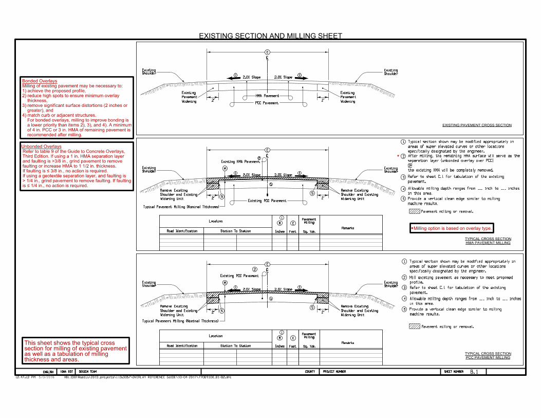
EXISTING SECTION AND MILLING SHEET
3
4
5
*2
3
Existing PCC Pavement
3
*Milling option is based on overlay type.
2specifically designated by the engineer.
areas of super elevated curves or other locations
Typical section shown may be modified appropriately in
profile.
Mill existing pavement as necessary to meet proposed
pavement.
Refer to sheet C.1 for tabulation of the existing
machine results.
Provide a vertical clean edge similar to milling
in this area.
Allowable milling depth ranges from ___ inch to ___ inches
specifically designated by the engineer.
areas of super elevated curves or other locations
Typical section shown may be modified appropriately in
pavement.
Refer to sheet C.1 for tabulation of the existing
in this area.
Allowable milling depth ranges from ___ inch to ___ inches
machine results.
Provide a vertical clean edge similar to milling
the existing HMA will be completely removed.
OR
separation layer (unbonded overlay over PCC)
After milling, the remaining HMA surface will serve as the
Pavement milling or removal.
Pavement milling or removal.
thickness and areas. as well as a tabulation of millingsection for milling of existing pavementThis sheet shows the typical cross
recommended after milling.
of 4 in. PCC or 3 in. HMA of remaining pavement is
a lower priority than items 2), 3), and 4). A minimum
For bonded overlays, milling to improve bonding is
4) match curb or adjacent structures.
greater), and
3) remove significant surface distortions (2 inches or
thickness,
2) reduce high spots to ensure minimum overlay
1) achieve the proposed profile,
Milling of existing pavement may be necessary to:
Bonded Overlays
is = 1/4 in., no action is required.
> 1/4 in., grind pavement to remove faulting. If faulting
If using a geotextile separation layer, and faulting is
If faulting is = 3/8 in., no action is required.
faulting or increase HMA to 1 1/2 in. thickness.
and faulting is >3/8 in., grind pavement to remove
Third Edition. If using a 1 in. HMA separation layer
Refer to table 9 of the Guide to Concrete Overlays,
Unbonded Overlays

V8i_IDOTRoad12:47:44 PM J:\2013_projects\113.0057\OVERLAY REFERENCE GUIDE\10-04-2017\77069100_B1-B2.sht
DESIGN TEAM PROJECT NUMBER SHEET NUMBER COUNTYENGLISH IOWA DOT
V8i_IDOTRoad12:47:44 PM J:\2013_projects\113.0057\OVERLAY REFERENCE GUIDE\10-04-2017\77069100_B1-B2.sht
DESIGN TEAM PROJECT NUMBER SHEET NUMBER COUNTYENGLISH IOWA DOT
5/3/2018
B.2
8
2% Slope 2% Slope
4.0" Min. Thickness4.0" Min. Thickness
4
3 3
Existing Pavement (20' Width)
4% Slope4% Slope
6
ExcavationExcavation
(Post Pav't. Milling)
Station To Station
S
Inches Feet
C
L
Feet
R
Feet
T
Feet FeetInches
Overlay Quantities
PCC
Overlay
Cu. Yds. Cu. Yds.
2 (Per Location)
PCC
Overlay
Sq. Yds. Feet
Excavation
2
1 14
Location
Road
for specific dimensions and quantities. bonded and unbonded overlays. A tabulation is givenThis sheet includes the typical cross sections for PCC
Subdrain
or Existing
Proposed
Subdrain
or Existing
Proposed
BW12 2
812.0' Min. 12.0' Min.
Proposed Bonded PCC Overlay 7
3
2
4
5
6
7
8
Layer
Subbase
Drainable
Layer
Subbase
Drainable
BONDED AND UNBONDED TYPICAL CROSS SECTION
Overlay Quantities
PCC
Overlay
Cu. Yds. Cu. Yds.
(Per Location)
PCC
Overlay
Sq. Yds.
Excavation
2
Road
8
2% Slope 2% Slope
4.0" Min. Thickness4.0" Min. Thickness
4
3 3Existing Pavement (20' Width)
4% Slope4% Slope
6(Post Pav't. Milling)
1 1
Excavation Excavation
812.0' Min.12.0' Min.
BW1
Subdrain
or Existing
Proposed
Subdrainor ExistingProposed
Proposed Unbonded PCC Overlay
Separation Layer
HMA or Geotextile7
2 2
3
2
Layer
Subbase
Drainable
Layer
Subbase
Drainable
4
5
6
7
8
4
9
9
9
working subdrainto ditch foreslope orDaylight geotextile layer
working subdrain
to ditch foreslope or
Daylight geotextile layer
cross slopes and transition rates.
the engineer. At existing super elevated areas match existing
super elevated curves or other locations specifically designated by
Typical section shown may be modified appropriately in areas of
Shoulder material as specified on sheet B.8.
Refer to jointing and widening details on sheet B.3
Refer to milling detail on sheet B.1.
Shoulder width varies by project.
Either drain to working subdrain or daylight fabric
the existing pavement will be removed.
side roads, and entrance intersections. At the existing paved intersections,
The contractor shall pave proposed shoulders thru all unpaved side road, paved
system using drainable subbase layer.
past the edge of the shoulders or connected into a longitudinal subdrain
or non-woven geotextile. The separation layer must be either daylighted
Separation layer may be either 1 inch well-drained asphalt surface mixture
pavement will be removed.
roads, and entrance intersections. At the existing paved intersections, the existing
The contractor shall pave proposed shoulders thru all unpaved side road, paved side
pavement is PCC. See sheet B.4.
non-woven vertical geotextile separation layer for drainage if existing
Provide a vertical clean edge similar to milling machine results. Use
sides.
Excavation quantities include trench width (BW) plus 1' x both Lt. & Rt.
sides.
Excavation quantities include trench width (BW) plus 1' x both Lt. & Rt.
Shoulder width varies by project.
and match curb or existing structures.
Milling should be considered to reduce high spots, remove distortions,
Existing Shoulder
Shoulder MaterialShoulder Material
Existing Shoulder
Shoulder Material
Existing Shoulder
Shoulder Material
Existing Shoulder
Refer to milling detail on sheet B.1.
Refer to jointing and widening details on sheet B.4.
Inches Feet Feet FeetFeetFeetFeetInchesStation To Station
LocationS C L R T BW1 BW2 G Remarks
BW1 BW2 G
RL
C
T
BW2
ST
ST
L
C
R
T
BW2
1
1
cross slopes and transition rates.
the engineer. At existing super elevated areas match existing
super elevated curves or other locations specifically designated by
Typical section shown may be modified appropriately in areas of
Shoulder material as specified on sheet B.8.
CL
CL
Remarks
UNBONDED OVERLAY
BONDED OVERLAY
Provide a vertical clean edge similar to milling machine results.
Note:
Note:
(AFTER PAVEMENT MILLING)
PCC UNBONDED OVERLAY WITH BASE WIDENING
TYPICAL CROSS SECTION
(AFTER PAVEMENT MILLING)
PCC BONDED OVERLAY WITH BASE WIDENING
TYPICAL CROSS SECTION

V8i_IDOTRoad2:56:14 PM J:\2013_projects\113.0057\OVERLAY REFERENCE GUIDE\10-04-2017\77069100_B3-B4-B5.sht
DESIGN TEAM PROJECT NUMBER SHEET NUMBER COUNTYENGLISH IOWA DOT
V8i_IDOTRoad2:56:14 PM J:\2013_projects\113.0057\OVERLAY REFERENCE GUIDE\10-04-2017\77069100_B3-B4-B5.sht
DESIGN TEAM PROJECT NUMBER SHEET NUMBER COUNTYENGLISH IOWA DOT
6/8/2021
B.3
1
2
3
7
12.0'12.0'
Proposed Saw Cut Spacing
(Concrete or HMA)
Original Pavement
ShoulderShoulder
Transverse Joint
Overlay
Width of new
in Existing Slab
Underlying Crack
Pavement
Concrete
Existing
Existing Slab
Saw Cut in
12'
Proposed Saw Cut Spacing
HMA Original Pavement
Shoulder
Concrete
4'-6'
4 4
5 5 5
6'-8'
Shoulder
Concrete
4'-6'
Proposed Final Paint Line Spacing (Saw Cuts Match Existing Underlying Pavement)
12'
< 12.0'
66
6'-8' < 12.0'
12'12'
Proposed Saw Cut Spacing
1 1
2" Min. 2" Min.
Concrete Original Pavement
222
3
6'-8' < 12.0' < 12.0'6'-8'
Shoulder
Concrete
4'-6'
Shoulder
Concrete
4'-6'
Overlay
Bonded
PCC
Overlay
Bonded
PCC
GENERAL NOTES
A.
Transverse Overlay Joint
Bonded Concrete Overlay
BONDED PCC OVERLAY JOINTING (WITH AND WITHOUT WIDENING)
3
4
5
6
KEYED NOTES:
X
Z
Y
54
1
Proposed Final Paint Line Spacing
A. Tie widening unit to existing concrete
Overlay
or Bonded
Unbonded
PCC
7
FULL DEPTH SAWCUT
WITH WIDENINGCOC-B TIE BAR LOCATION
KEYED NOTES:
if no widening unit, excavate and place drainable subbase.
if concrete, unit may remain if stable, and 3' wide,
if Asphalt, remove unit,
Existing widening unit:
Full depth plus 1/2"
existing concrete30'' spacing. Drill and epoxy bars into
Epoxy coated No. 4 tie bar 36'' long at
connect to working subdrain
daylight to ditch foreslope or
Place drainable subbase layer and
connect to working subdrain
daylight to ditch foreslope or
Place drainable subbase layer and
If BCOA, then use T/3 sawcut.
If BCOC, then use full depth sawcut.
B.
v
v
2
v
Secure bar in 3 locations
KEYED NOTES
WITHOUT WIDENING
CONCRETE ON CONCRETE OR ASPHALT - BONDED OVERLAY
if no widening unit, excavate and place drainable subbase.
if concrete, unit may remain if stable, and 3' wide,
if Asphalt, remove unit,Existing widening unit:
T/3 saw cut (do not sever bar)
above the bar. Tie bars are No. 4 bars 36" long @ 30" centers.
accommodate maximum sized aggregate under the bar and minimum 2"
mid-depth. Placement must allow adequate overlay thickness to
Consideration shall be given to placement of epoxy coated tie bar at
paved shoulders/widening unit.
5" and no drainable subbase, do not use tie bars in the
minimum of three staples or epoxy. For concrete overlays
unit, secure the tie bar to the asphalt pavement, using a
with drainable subbase under the paved shoulder/widening
For bonded concrete overlays 5" and in cold weather states
A. Tie bar placement with overlay thickness 5"
Match existing joint locations.Cut transverse joints to full depth plus 1/2".
location of sawcut, thickened edge, restraint and use of fibers.
explanation on pavement widening drainage, location of tie bar,
the Development of Overlay Construction Documents" for
Refer to "Design Lessons Learned" in the document "Guide for
CONCRETE ON CONCRETE - BONDED OVERLAY WITH WIDENING
Minimum 4 ft. paved shoulder
"X" must be Z+0.125 in.
prevent intrusion of mortar during overlay placement. In all cases,
for a bonded overlay. The existing joints should be filled/sealed to
condition, the existing pavement may not be a good candidate
required to eliminate faulting. If there are numerous joints with this
evaluated to determine if load transfer rehabilitation is
pavement does not have dowel bars, the joints should be
measured. If crack "Z" is 0.25 in. or greater, and existing
underlying crack width in the existing slab should be
of the existing slab. If "Y" is 0.50 in. or greater, the
Overlay joint width shall be equal to or greater than crack width
Note:
paved shoulder is recommended
0.5 in. If construction is completed under traffic, a 4 ft
joints. Transverse joints shall be cut to full depth plus
concrete, new joints in the overlay shall align with existing
overlays and widening units. For bonded overlays on
This sheet illustrates the jointing layout for PCC bonded
COC-B
COC-B or COA-B
COA-B = Concrete on Asphalt - Bonded Overlay
COC-B = Concrete on Concrete - Bonded Overlay
COA-B
WITH WIDENING
COA-B TIE BAR LOCATIONS
CONCRETE ON ASPHALT - BONDED OVERLAY WITH WIDENING
overlay of existing concrete pavement)
(Transverse and longitudinal joint detail in concrete
(COC-B) CONCRETE ON CONCRETE - BONDED OVERLAY
V8i_IDOTRoad2:56:30 PM J:\2013_projects\113.0057\OVERLAY REFERENCE GUIDE\10-04-2017\77069100_B3-B4-B5.sht
DESIGN TEAM PROJECT NUMBER SHEET NUMBER COUNTYENGLISH IOWA DOT
V8i_IDOTRoad2:56:30 PM J:\2013_projects\113.0057\OVERLAY REFERENCE GUIDE\10-04-2017\77069100_B3-B4-B5.sht
DESIGN TEAM PROJECT NUMBER SHEET NUMBER COUNTYENGLISH IOWA DOT
6/8/2021
B.4
Proposed Saw Cut Spacing
OverlayUnbondedPCC
12.0'12.0'
WideningConcrete
WideningConcrete
8" Min.
< 12.0' < 12.0'
Concrete Original Pavement
Thickness5" Min.
1.5' 1.5'
Widening
ShoulderOverlayConcreteUnbonded
3" Min.
PavementOriginalConcrete
Proposed Final Paint Line Spacing
2
PavementOriginal
Compositeor
Asphalt
1
2
3
4
5
A.
B.
C.
Widening
Shoulder
1.5' 1.5'
1" HMA Separation Layer
8" Min.
PavementOriginalConcrete
OverlayConcreteUnbonded
D.
joint detailSee bar
joint detailSee bar
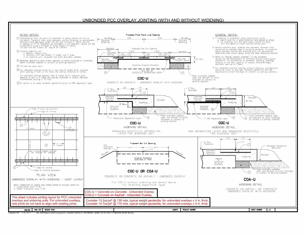
UNBONDED PCC OVERLAY JOINTING (WITH AND WITHOUT WIDENING)
Widening
OverlayConcreteUnbonded
1.5' 1.5'
C= Sawed Transverse Joint (T/3)
L= Longitudinal Joint (T/3)
Note: Dimensions of panels may change based on project specifics
VariableVariable
Variable
Variable
new joints do not have to align with existing joints.
overlays and widening units. For unbonded overlays,
This sheet includes jointing layout for PCC unbonded
2
2
or connect to working subdrainand daylight to ditch foreslopePlace drainable subbase layer
or connect to working subdrainlayer and daylight to ditch foreslopePlace drainable subbase
working subdrainforeslope or connect tolayer and daylight to ditchPlace drainable subbase
Geotextile Separation Layer
Thickness5" Min.
6' Typical
'C'
Joint
'L' Joint
36'' long at 30'' spacingNo. 4 epoxy coated tie bar
on centerspacing
30''
panelbars per
Min. 2
Edge of overlay
Edge of existing pavement
Edge of overlay
Shoulder
(Optional)Nonwoven Geotextile
12.0'12.0'
Proposed Saw Cut Spacing
(Concrete or HMA)
Original Pavement
ShoulderShoulder
COA-U = Concrete on Asphalt - Unbonded Overlay
COC-U = Concrete on Concrete - Unbonded Overlay
UNBONDED OVERLAY WITH WIDENING - JOINT LAYOUT
LAYER FOR WIDENING UNITNONWOVEN GEOTEXTILE SEPARATION
COC-U COC-U
FOR WIDENING UNITHMA SEPARATION LAYER AND NONWOVEN GEOTEXTILE
CONCRETE ON CONCRETE - UNBONDED OVERLAY WITH WIDENING
COC-U
PLAN VIEW
COA-U
1
COC-U OR COA-U
WIDENING DETAIL WIDENING DETAIL
WIDENING DETAIL
Overlay
Unbonded
PCC
1 1
11
2 2
22
3
4 4
44 4
Thickness5" Min.
NEW HMA ORGEOTEXTILE SEPARATION LAYER
working subdrainforeslope or connect tolayer and daylight to ditchPlace drainable subbase
5
6
6
v
T/3
T/3
An option is to place nonwoven geotextile prior to HMA separation layer
recommended spacing is 15 feet.spacing in feet is 2 times the overlay thickness in inches. Maximum For unbonded overlays greater then 6 inches thick, maximum joint
joint spacing in feet is 1.5 times the overlay thickness in inches. For unbonded overlays equal to or less than 6 inches thick, maximum
T/3 (do not sever bar) above drainable subbase or connect to working subdrain.Nonwoven geotextile shall either daylight to ditch foreslope or terminate
if no widening unit, excavate and place drainable subbase. if concrete, unit may remain if stable, and 3' wide, if Asphalt, remove unit,Existing widening unit:
Tie bars are No. 4 bars 36" long @ 30" centers.to pavement using a minimum of three staples or epoxy. If overlay is 5" or placement at mid-depth is not possible, secure tie bar maximum sized aggregate under the bar and minimum 2" above the bar. mid-depth. Placement must allow adequate overlay thickness to accommodate Consideration shall be given to placement of epoxy coated tie bar at
Edge of existing pavement
for draining separation layer
For COC-U without widening, see detail above
separation to ditch foreslope or connect to working subdrain.should be given to day-light nonwoven geotextile and HMA For unbonded concrete overlays without widening, consideration
restraint and use of fibers. location of tie bar, location of sawcut, thickened edge, Documents" for explanation on pavement widening, drainage, "Guide for the Development of Concrete Overlay Construction Refer to "Design Lessons Learned", in the document
dimensions and locate sawcut using the same measuring method. sawcut between overlay and widening unit, use documented centerline to outside edge of existing pavement. To establish Before concrete pour, measure and document distance from
Drill and epoxy or insert during overlay pour. b. Tie widening unit with No.4 epoxy coated tie bars. a. Fabric must be in good condition and placed as shown.If widening is completed using construction joint:
GENERAL NOTES:KEYED NOTES:
Consider 14.7oz/yd² @ 170 mils, typical weight geotextile, for unbonded overlays > 5 in. thick.
Consider 13.3oz/yd² @ 130 mils, typical weight geotextile, for unbonded overlays < 4 in. thick.
CONCRETE ON CONCRETE OR ASPHALT - UNBONDED OVERLAY
UNBONDED OVERLAY WITH WIDENINGCONCRETE ON ASPHALT OR COMPOSITE
V8i_IDOTRoad12:54:06 PM J:\2013_projects\113.0057\OVERLAY REFERENCE GUIDE\10-04-2017\77069100_B3-B4-B5.sht
DESIGN TEAM PROJECT NUMBER SHEET NUMBER COUNTYENGLISH IOWA DOT
V8i_IDOTRoad12:54:06 PM J:\2013_projects\113.0057\OVERLAY REFERENCE GUIDE\10-04-2017\77069100_B3-B4-B5.sht
DESIGN TEAM PROJECT NUMBER SHEET NUMBER COUNTYENGLISH IOWA DOT
5/3/2018
B.5
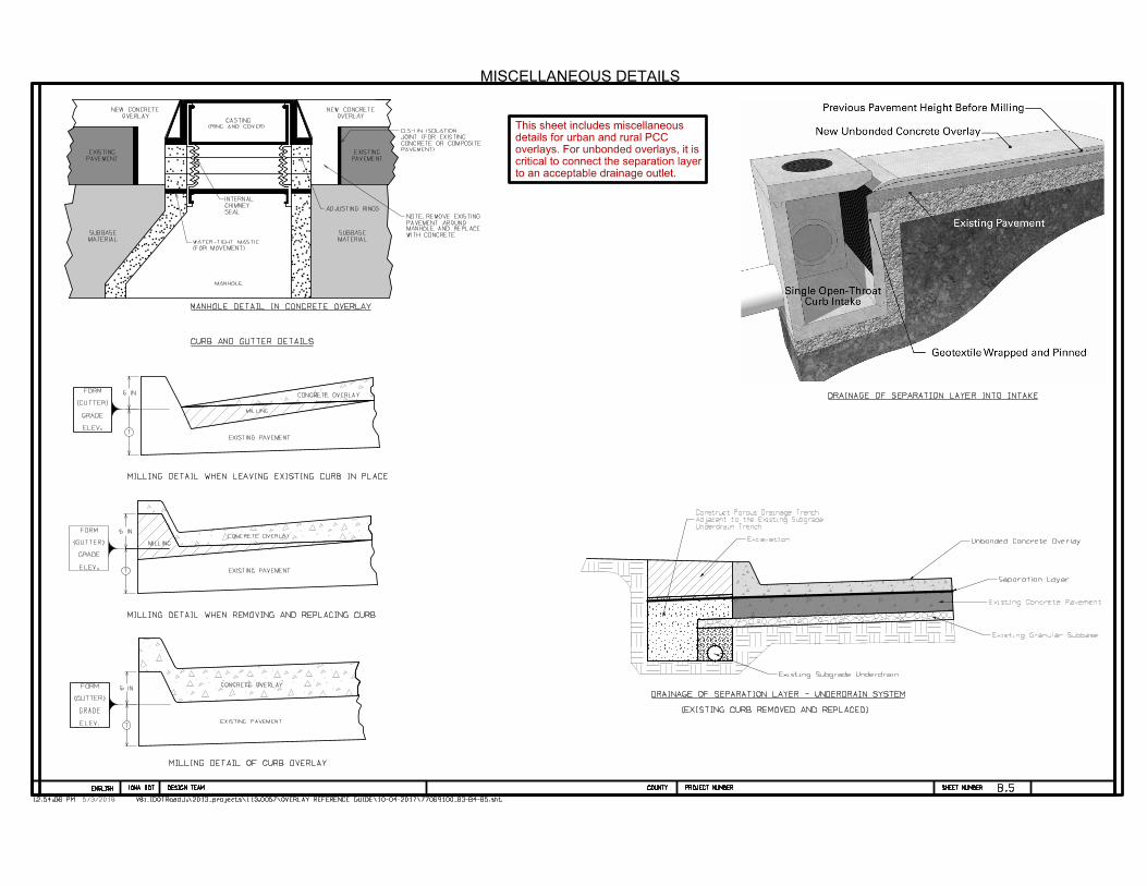
MISCELLANEOUS DETAILS
EXISTING PAVEMENTT
6 IN
T
6 IN
T
6 IN
EXISTING PAVEMENT
EXISTING PAVEMENT
CONCRETE OVERLAY
CONCRETE OVERLAY
CONCRETE OVERLAY
MILLING
MILLING
WITH CONCRETE
MANHOLE AND REPLACE
PAVEMENT AROUND
NOTE: REMOVE EXISTING
(RING AND COVER)
CASTING
(FOR MOVEMENT)
WATER-TIGHT MASTIC
MANHOLE
SEAL
CHIMNEY
INTERNAL
ADJUSTING RINGS
OVERLAY
NEW CONCRETE
PAVEMENT
EXISTING
MATERIAL
SUBBASE
PAVEMENT
EXISTING
MATERIAL
SUBBASE
OVERLAY
NEW CONCRETE
PAVEMENT)
CONCRETE OR COMPOSITE
JOINT (FOR EXISTING
0.5-1 IN. ISOLATION
ELEV.
GRADE
(GUTTER)
FORM
ELEV.
GRADE
(GUTTER)
FORM
ELEV.
GRADE
(GUTTER)
FORM
MILLING DETAIL WHEN LEAVING EXISTING CURB IN PLACE
MILLING DETAIL WHEN REMOVING AND REPLACING CURB
MILLING DETAIL OF CURB OVERLAY
CURB AND GUTTER DETAILS
DRAINAGE OF SEPARATION LAYER INTO INTAKE
MANHOLE DETAIL IN CONCRETE OVERLAY
(EXISTING CURB REMOVED AND REPLACED)
DRAINAGE OF SEPARATION LAYER - UNDERDRAIN SYSTEM
Excavation
Underdrain TrenchAdjacent to the Existing SubgradeConstruct Porous Drainage Trench
Unbonded Concrete Overlay
Separation Layer
Existing Concrete Pavement
Existing Granular Subbase
Existing Subgrade Underdrain
to an acceptable drainage outlet.
critical to connect the separation layer
overlays. For unbonded overlays, it is
details for urban and rural PCC
This sheet includes miscellaneous
V8i_IDOTRoad12:55:04 PM J:\2013_projects\113.0057\OVERLAY REFERENCE GUIDE\10-04-2017\77069100_B6-B7-B8-B9.sht
DESIGN TEAM PROJECT NUMBER SHEET NUMBER COUNTYENGLISH IOWA DOT
V8i_IDOTRoad12:55:04 PM J:\2013_projects\113.0057\OVERLAY REFERENCE GUIDE\10-04-2017\77069100_B6-B7-B8-B9.sht
DESIGN TEAM PROJECT NUMBER SHEET NUMBER COUNTYENGLISH IOWA DOT
5/3/2018
B.6
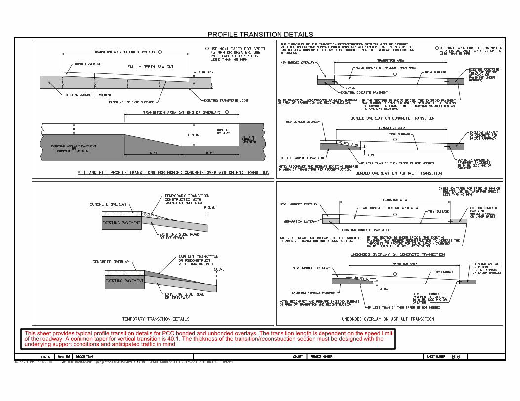
6PROFILE TRANSITION DETAILS
FULL - DEPTH SAW CUT
H
1
1
TRANSITION AREA (AT END OF OVERLAY)
TRANSITION AREA (AT END OF OVERLAY)
IN AREA OF TRANSITION AND RECONSTRUCTION.
NOTE: RECOMPACT AND RESHAPE EXISTING SUBBASE
CAPABILITIES AS THE OVERLAY SECTION.
THICKNESS TO PROVIDE FOR EQUAL LOAD - CARRYING
PAVEMENT MAY REQUIRE RECONSTRUCTION TO INCREASE THE
IF THE SECTION IS UNDER BRIDGE, THE EXISTING
NEW UNBONDED OVERLAY
PLACE CONCRETE THROUGH TAPER AREA
TRIM SUBBASE
30 FT: I IN.
IN AREA OF TRANSITION AND RECONSTRUCTION.
NOTE: RECOMPACT AND RESHAPE EXISTING SUBBASE GREATER
IS 8 IN. (200 MM) OR
PAVEMENT THICKNESS
DOWEL IF CONCRETE
TRANSITION AREA
TRANSITION AREA
NEW UNBONDED OVERLAY
EXISTING ASPHALT PAVEMENT
TRIM SUBBASE
1
1OR UNDER BRIDGE)
(BRIDGE APPROACH
OR CONCRETE
EXISTING ASPHALT
OR UNDER BRIDGE)
(BRIDGE APPROACH
PAVEMENT
EXISTING CONCRETE
EXISTING CONCRETE PAVEMENT
TRIM SUBBASE
IN AREA OF TRANSITION AND RECONSTRUCTION.
NOTE: RECOMPACT AND RESHAPE EXISTING SUBBASE
DOWEL
PLACE CONCRETE THROUGH TAPER AREA
TRANSITION AREA
20 FT: 1 IN.
TRIM SUBBASE
TRANSITION AREA
1
BRIDGES)
PAVEMENT UNDER
APPROACH OR
PAVEMENT (BRIDGE
EXISTING CONCRETE
NEW BONDED OVERLAY
1
R.O.W.
GRANULAR MATERIAL
CONSTRUCTED WITH
TEMPORARY TRANSITION
OR DRIVEWAY
EXISTING SIDE ROAD
CONCRETE OVERLAY
CONCRETE OVERLAY
R.O.W.
OR DRIVEWAY
EXISTING SIDE ROAD
LESS THAN 45 MPH
GREATER. USE 25:1 TAPER FOR SPEEDS
USE 40:1 TAPER FOR SPEED 45 MPH OR1
LESS THAN 45 MPH
GREATER. USE 25:1 TAPER FOR SPEEDS
USE 40:1 TAPER FOR SPEED 45 MPH OR1
2 IN. MIN.
H+3 IN.
3 IN.6 FT6 FT
3 IN.
1
NEW BONDED OVERLAY
EXISTING ASPHALT PAVEMENT
IN AREA OF TRANSITION AND RECONSTRUCTION.
NOTE: RECOMPACT AND RESHAPE EXISTING SUBBASE
IF LESS THAN 5" THEN TAPER IS NOT NEEDED
underlying support conditions and anticipated traffic in mindof the roadway. A common taper for vertical transition is 40:1. The thickness of the transition/reconstruction section must be designed with the This sheet provides typical profile transition details for PCC bonded and unbonded overlays. The transition length is dependent on the speed limit
WITH HMA OR PCC
OR RECONSTRUCT
ASPHALT TRANSITION
EXISTING PAVEMENT
EXISTING PAVEMENT
OVERLAY
BONDED
PAVEMENTASPHALTEXISTING
COMPOSITE PAVEMENTOR
EXISTING ASPHALT PAVEMENT
EXISTING CONCRETE PAVEMENT
TAPER MILLED INTO SURFACEEXISTING TRANSVERSE JOINT
LESS THAN 45 MPH
25:1 TAPER FOR SPEEDS
45 MPH OR GREATER. USE
USE 40:1 TAPER FOR SPEED
BONDED OVERLAY
BONDED OVERLAY ON CONCRETE TRANSITION
THICKNESS
HAS NO RELATIONSHIP TO THE OVERLAY THICKNESS NOR THE OVERLAY PLUS EXISTING
WITH THE UNDERLYING SUPPORT CONDITIONS AND ANTICIPATED TRAFFIC IN MIND. IT
THE THICKNESS OF THE TRANSITION/RECONSTRUCTION SECTION MUST BE DESIGNED
THE OVERLAY SECTION.
TO PROVIDE FOR EQUAL LOAD - CARRYING CAPABILITIES AS
MAY REQUIRE RECONSTRUCTION TO INCREASE THE THICKNESS
IF THE SECTION IS UNDER BRIDGE, THE EXISTING PAVEMENT
BRIDGE APPROACH
OR CONCRETE FOR
EXISTING ASPHALT
GREATER
IS 8 IN. (200 MM) OR
PAVEMENT THICKNESS
DOWEL IF CONCRETE
SEPARATION LAYER
EXISTING CONCRETE PAVEMENT
UNBONDED OVERLAY ON CONCRETE TRANSITION
IF LESS THAN 5" THEN TAPER IS NOT NEEDED
UNBONDED OVERLAY ON ASPHALT TRANSITIONTEMPORARY TRANSITION DETAILS
MILL AND FILL PROFILE TRANSITIONS FOR BONDED CONCRETE OVERLAYS ON END TRANSITION BONDED OVERLAY ON ASPHALT TRANSITION
V8i_IDOTRoad12:55:35 PM J:\2013_projects\113.0057\OVERLAY REFERENCE GUIDE\10-04-2017\77069100_B6-B7-B8-B9.sht
DESIGN TEAM PROJECT NUMBER SHEET NUMBER COUNTYENGLISH IOWA DOT
V8i_IDOTRoad12:55:35 PM J:\2013_projects\113.0057\OVERLAY REFERENCE GUIDE\10-04-2017\77069100_B6-B7-B8-B9.sht
DESIGN TEAM PROJECT NUMBER SHEET NUMBER COUNTYENGLISH IOWA DOT
5/3/2018
B.7
4.0%
(Adjacent to new PCC Overlay Pavement)
4.0%
In-Place
& Embankment-
Excav.
(Use As Constructed)
and PCC Paved Shoulders
Existing PCC Bridge Approach Pavement
Sta. 170+56
Sta. 172+47
Prop. PCC Inlay Pavement & Paved Shoulders
170
175
+88
& Paved Shoulders
Prop. PCC Inlay Pavement
Sta. 169+59
+40
Bridge
36'24'
+63
36'
(4' Width)
Strengthening - Lt. & Rt.
Remove Existing Shoulder
24'
+78
+15
PCC Overlay
Sheet B.8
Refer to Typical on
Prop. Paved Shoulder
Sheet B.8
Refer to Typical on
Prop. Paved Shoulder
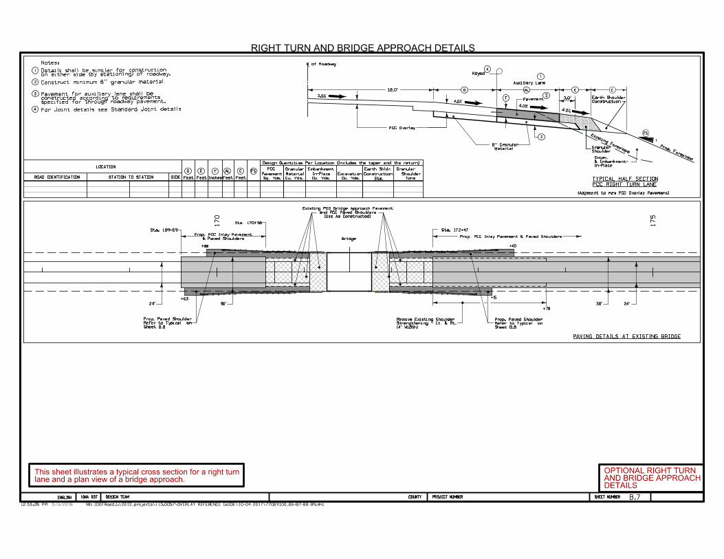
RIGHT TURN AND BRIDGE APPROACH DETAILS
D E
FeetFeetROAD IDENTIFICATION STATION TO STATION
LOCATION
T
InchesSIDE Feet
AL
Feet
FSC
Granular
Tons
Shoulder
PCC
Pavement
Sq. Yds. Cu. Yds. Sta.
Earth Shldr.
Granular
Material
Cu. Yds. Cu. Yds.
Embankment
In-Place Excavation Construction
Design Quantities Per Location (Includes the taper and the return)
2.0%
C of Roadway
4.0%
12.0' D
L
1
3.0'
AL
3
Construction
Earth Shoulder
CE
Auxiliary Lane
PavementT
4
Keyed
2Existing Foreslope
1
Prop. Foreslope
FS
Shoulder
Granular
3
Notes:
constructed according to requirementsspecified for through roadway pavement.
Pavement for auxiliary lane shall be
1
4
on either side (by stationing) of roadway.
2
For Joint details see Standard Joint details
7Construct minimum 8'' granular material.
Material
8'' Granular
lane and a plan view of a bridge approach.This sheet illustrates a typical cross section for a right turn
DETAILSAND BRIDGE APPROACHOPTIONAL RIGHT TURN
PCC RIGHT TURN LANE
TYPICAL HALF SECTION
PAVING DETAILS AT EXISTING BRIDGE
Details shall be similar for construction
V8i_IDOTRoad12:56:29 PM J:\2013_projects\113.0057\OVERLAY REFERENCE GUIDE\10-04-2017\77069100_B6-B7-B8-B9.sht
DESIGN TEAM PROJECT NUMBER SHEET NUMBER COUNTYENGLISH IOWA DOT
V8i_IDOTRoad12:56:29 PM J:\2013_projects\113.0057\OVERLAY REFERENCE GUIDE\10-04-2017\77069100_B6-B7-B8-B9.sht
DESIGN TEAM PROJECT NUMBER SHEET NUMBER COUNTYENGLISH IOWA DOT
5/3/2018
& Overlay
PCC Widening
1
2
Overlay
PCC
17'
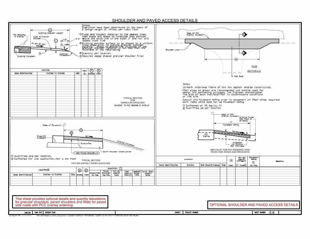
Uniform thickness fillets of hot mix asphalt shall be constructed.
Road Identification
Location
Remarks
Station
Quantities as per location.
HMA Thickness
3.5'' Minimum
Proposed
Variable
Overlay Pavement
Edge of PCC
Road Identification Station to Station Side
D
Excavation
Feet
E
Inches Cu. Yds.
Earth Shldr.
Constr.
Stas.
Pavement Milling
SECTION A-A
B.8
both items will be paid for as Pavement Milling.
Sawcut and Pavement Milling prior to placement of fillet will be required;
SHOULDER AND PAVED ACCESS DETAILS
A
A
W
Overlay Pavement
Edge of PCC
PLAN
Shoulder Line
Side RoadLC
1
Existing shoulder surface to be shaped to a uniformcross slope prior to placing granular shoulder
1
2
3
ROAD IDENTIFICATION STATION TO STATION SIDE
TONS
3
E
T
1
E
FeetInches
T
2
LOCATION
Existing Shoulder Length
4 Requires wedge shaped granular shoulder fillet.
ADJACENT TO PCC WIDENING & OVERLAY
1'-O''O'-6''
Quantity per location.
LocationQUANTITIES 1
5
thickness of the resurfacing.
TYPICAL SECTION
HOT MIX ASPHALT PAVED SHOULDER
GRANULAR SHOULDER
FOR
TYPICAL SECTION
ForeslopeExisting
Existing Pavement
Shoulder
Type 'B' Granular
4% Min. 6% Max.1:1
E
D
Quantities are per location.
HMA Paved Shoulder, 6"
Pavement
Prop. PCC
Existing Foreslope
Earth Shoulder Construction
Edge of Pavement
4.O%
2
2Tons
Asphalt
Hot MixPaved
Shoulder
Sq. Yds. Gals.
Coat
Tack
Tons
Binder
Asphalt
1
W
Feet Sq. Yds.Side Tons 2
23.5" Depth
Asphalt
Hot Mix
Side Road/Driveway
Milling
Pavement
PAVED SIDE ROADS AND DRIVEWAYS
HMA FILLET FOR PCC WIDENING THRU
8Excavation
loaded truck tire.above the solid line in the outer 2' and roll withthen blade and shape to foreslope that portionPlace and compact material to the dashed lines;
Estimated for one application. (Not a bid item)
Driveway
Side Road or
Existing Paved
OPTIONAL SHOULDER AND PAVED ACCESS DETAILS
material. Shape to ensure the thickness of the
Note:
at the site.the size of each individual fillet to accommodate conditionsdesign and estimating purposes. The Engineer shall establishFillet sizes as shown are recommended and shall be used for
Estimated at 145 lbs./cu. ft.
granular shoulder material is not less than the
a design weight of 140lbs. per cubic foot.Quantities have been determined on the basis ofNotes:
side roads with PCC overlay widening. for granular shoulders, paved shoulders and fillets for paved This sheet provides optional details and quantity tabulations

V8i_IDOTRoad12:57:40 PM J:\2013_projects\113.0057\OVERLAY REFERENCE GUIDE\10-04-2017\77069100_B6-B7-B8-B9.sht
DESIGN TEAM PROJECT NUMBER SHEET NUMBER COUNTYENGLISH IOWA DOT
V8i_IDOTRoad12:57:40 PM J:\2013_projects\113.0057\OVERLAY REFERENCE GUIDE\10-04-2017\77069100_B6-B7-B8-B9.sht
DESIGN TEAM PROJECT NUMBER SHEET NUMBER COUNTYENGLISH IOWA DOT
5/3/2018
B.9
P
20'
Normal Shoulder
Edge of
Form Board Required
A
Location
Final Guardrail
3
A
B B
4
P
4%
10:1
Normal Shoulder
Edge of
10:1
Normal Shoulder Width
C
C
GUARDRAIL AND PAVED SHOULDER DETAIL
2
Roll down at granular shoulder or earth.
24''
Width
Shoulder
Normal
10:1
Point
Hinge
Road Identification Station To Station
Location
Side
Subgrade
Feet
P
Remarks
Treatment
1
SY
Shoulder
Paved
Type
CY
ExcavationPavement
Edge of
Pavement
Edge of
Continue paved shoulder to existing paved shoulder or 20' beyond the
end of guardrail.
3
4
2
nail 1" x 6" untreated form boards along the face of guardrail posts for
When guardrail posts are installed prior to construction of paved shoulder,
1
the length shown. This board is to prevent shoulder material from contacting
6" HMA Paved Shoulder at guardrail. 7" PCC may be substituted with the
following jointing layout:
Compaction of HMA is required to face of guardrail post. Hand compaction will
be allowed under guardrail.
with no additional payment. Removal & reinstallation of guardrail will be allowed
6'' subgrade treatment (not required on this project).
the sides of the posts and altering the function of the guardrail.
Form board not required for final 2 posts.
4.O%
Pavement
MainlinePaved Shoulder
Normal Foreslope
Hinge Point
4.O%
Normal Foreslope
1
3''
1
2
Edge of Pavement
Variable Slope
Variable Slope
for guardrail details.
Follow jurisdiction standards
Note:
PAVED SHOULDER DETAILOPTIONAL GUARDRAIL AND
joint less than 10' in length.10' wide. Terminate longitudinal joint at transverse from edge of mainline pavement when W is greater than the mainline pavement. Place longitudinal joint at W/2 additional transverse joints in shoulder at mid-panel of pavement is 8" or greater in thickness, place Match mainline pavement joint spacing. When mainline
sleeves may be installed through pavement. Shoulder may be notched for final 2 posts or post
Section B-B
Pavement
MainlinePaved Shoulder
Section C-C with Form Board
Section A-A
information. guardrail design and construction prior to utilization of this It is important to review local jurisdictional or agency standards forThis sheet provides details and quantity tabulations for a guardrail.
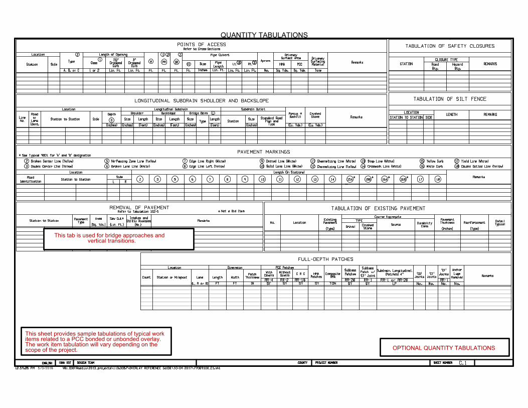
C.1
QUANTITY TABULATIONS
Remarks
Surface AreaDriveway
Size
Location
Station Side
POINTS OF ACCESSRefer to Cross-Sections
Ft. H
Lin. Ft. Lin. Ft. Tons
MaterialSurfacingDriveway
Aprons
No.Lin. Ft.
CurbDropped
1•"
CurbDropped
3"
Lin. Ft.A, B, or C
TypeCase
1 2 2
W
Ft. Ft.
PR
Ft.
SRLt. Rt.
2
1 Pipe
Length
Inches Lin. Ft.
Length of Opening
2 2 2 2
1 or 2 Sq. Yds.
HMA
Sq. Yds.
PCC
Pipe Culvert
STATION
TABULATION OF SAFETY CLOSURES
REMARKS
CLOSURE TYPE
Qty.
Road
Qty.
Hazard
Location Longitudinal Subdrain
No.
Line
Ident.
Lane
or
Road
Station to Station Side D
Depth Shoulder Backslope Bridge Berm
BackfillPorous *
RemarksSize Size SizeLength Length Length
TypeSize
(Inches) (Inches) (Inches) (Inches)(Feet) (Feet) (Feet)
Station
(Cu. Yds.) (Cu. Yds.)
1
Subdrain Outlet
LONGITUDINAL SUBDRAIN SHOULDER AND BACKSLOPE
(Inches) TypePlan and
Standard RoadStone
Crushed
Location
Road
Identification L2 3Station to Station
2
3
5
6
Side
R
Length (In Stations)
5 6 7 8 9 1O 11 12
7
8Broken Lane Line (White)
9Edge Line Right (White)
1OEdge Line Left (Yellow)
Dotted Line (White)
13 14Remarks
11
12
13
14
15
16
Channelizing Line (White)
Channelizing Line (Yellow)
Stop Line (White)
Crosswalk Line (White)
Yellow Curb
White Curb
Broken Center Line (Yellow)
Double Center Line (Yellow)
No-Passing Zone Line (Yellow)
17
17 Yield Line (White)
18
18 Double Dotted Line (Yellow)
15A 16A15B 16B
Solid Lane Line (White)
PAVEMENT MARKINGS* See Typical 9001 for 'A' and 'B' designation
* * * *
REMOVAL OF PAVEMENT
Station to StationType
Pavement
(Sq. Yds.)
Area
(Lin. Ft.)
Saw Cut*Remarks
Not a Bid Item*
(No.)
Utility AccessesIntakes and
Refer to Tabulation 102-5
No. Location
(Type)
PavementExisting
Coarse Aggregate
TYPE
GravelStone
Crushed Source
(Inches)
ThicknessPavement
TypicalDetail
TABULATION OF EXISTING PAVEMENT
ClassDurability
(Type)
Reinforcement
Location Dimension PCC Patches
Count Station or MilepostRemarks
FULL-DEPTH PATCHES
IN
ThicknessPatch
FT
Width
FT
Length
(L, R or B)
LaneRR-4
DowelsWith
SY
RR-2 RR-1RR-18 RR-26
SY
RR-1
Joints'CT'
Joints'CD'
No.No.
Joints
'EF'
No.
Removal
Lugs
Anchor
No.
Patches
Subbase
SY
(Patches) 4''
Subdrain, Longitudinal,
LFSY SY
DowelsWithout
C R C
SY
HMAComposite
TON
PatchesHMA
'EF' Joint
w/Patch
Subbase
RR-1 or RR-26
REMARKS
TABULATION OF SILT FENCE
LOCATION
STATION TO STATION LENGTH
SIDE
OPTIONAL QUANTITY TABULATIONS
vertical transitions.This tab is used for bridge approaches and
scope of the project. The work item tabulation will vary depending on theitems related to a PCC bonded or unbonded overlay.This sheet provides sample tabulations of typical work
V8i_IDOTRoad12:59:05 PM J:\2013_projects\113.0057\OVERLAY REFERENCE GUIDE\10-04-2017\77069100_C1.sht
DESIGN TEAM PROJECT NUMBER SHEET NUMBER COUNTYENGLISH IOWA DOT
V8i_IDOTRoad12:59:05 PM J:\2013_projects\113.0057\OVERLAY REFERENCE GUIDE\10-04-2017\77069100_C1.sht
DESIGN TEAM PROJECT NUMBER SHEET NUMBER COUNTYENGLISH IOWA DOT
5/3/2018 V8i_IDOTRoad12:59:05 PM J:\2013_projects\113.0057\OVERLAY REFERENCE GUIDE\10-04-2017\77069100_C1.sht
DESIGN TEAM PROJECT NUMBER SHEET NUMBER COUNTYENGLISH IOWA DOT
V8i_IDOTRoad12:59:05 PM J:\2013_projects\113.0057\OVERLAY REFERENCE GUIDE\10-04-2017\77069100_C1.sht
DESIGN TEAM PROJECT NUMBER SHEET NUMBER COUNTYENGLISH IOWA DOT
5/3/2018

D.1
EXISTING PLAN AND PROFILE SHEETS
EXISTING ROADWAY PLAN AND PROFILE FOR REFERENCE ONLY
OPTIONAL ROADWAY PLAN AND PROFILEdrawings.only and, typically, the PCC overlay profile is not included in the design placed. The plan and profile for the existing pavement is used for reference existing roadway where the PCC bonded or unbonded overlay is to be This sheet is a placeholder to provide plan and profile information for the
V8i_IDOTRoad1:00:16 PM J:\2013_projects\113.0057\OVERLAY REFERENCE GUIDE\10-04-2017\77069100_D1.sht
DESIGN TEAM PROJECT NUMBER SHEET NUMBER COUNTYENGLISH IOWA DOT
V8i_IDOTRoad1:00:16 PM J:\2013_projects\113.0057\OVERLAY REFERENCE GUIDE\10-04-2017\77069100_D1.sht
DESIGN TEAM PROJECT NUMBER SHEET NUMBER COUNTYENGLISH IOWA DOT
5/3/2018

J.1
STAGING NOTES TRAFFIC CONTROL PLAN
COORDINATED OPERATIONS
STAGING AND TRAFFIC CONTROL NOTES
those of other contractors working within the same area.
the construction of the projects listed. Coordinate operations with
Other work in progress during the same period of time will include
Pavement Markings
Guardrail updates
Paved Shoulders
Granular Shoulders
PCC / HMA tie-in work at side roads
Right turn lane construction
PCC Overlay and Widening / PCC Reconstruction Areas
Excavation for PCC Widening and Subbase Placement
CONSTRUCTION
Through traffic on Mainline shall be detoured
TRAFFIC CONTROL
Phase 2B
Pavement Markings
Guardrail updates
Paved Shoulders
Granular Shoulders
PCC / HMA tie - in work at side roads
Right turn lane construction
PCC Inlay Pavement / PCC Reconstruction Areas / PCC Overlay Pavement
Excavation for PCC Widening and Subbase Placement
CONSTRUCTION
Through traffic on Mainline shall be detoured (refer to Detour #1 map on sheet A.1).
TRAFFIC CONTROL
Phase 2A
STAGE 2
Pavement Milling
Full Depth Patching
CONSTRUCTION
During night time hours lane closures will not be allowed.
A minimum of one traffic lane shall be maintained on Mainline during daytime hours.
TRAFFIC CONTROL
STAGE 1
TRAFFIC CONTROLOPTIONAL STAGING AND
1
2
3
4
5 If Mainline is open to traffic, no lane closures will be allowed during the following events:
in similar locations.
pavement marking prior to removing or obliterating them to insure their replacements are positioned
Unless otherwise directed, the contractor shall take appropriate measurements of the existing
Traffic control on the project shall be in accordance with MUTCD, current edition.
including school bus traffic. No more than two (2) side roads closed at any time.
The contractor shall maintain access at all times for residents who live and work along mainline,
detour use is allowed.
Maintenance personnel. The contractor shall provide a 2 week notice to the engineer before any
Mainline detour route (refer to map on sheet A.1) shall be signed and maintained by the jurisdiction
Through traffic on Mainline shall be staged to allow work under traffic and work while detoured.
prior to construction. critical that the contractor submits traffic control and staging plans for review operations and possibly making construction operations more efficient. It is detailed staging plans. This gives the contractor flexibility in setting up staging is required, it is recommended to list specific staging criteria instead of drawing contractor will need to follow during construction. If specific staging or phasing This sheet is required to list specific staging notes and criteria that the
V8i_IDOTRoadJ:\2013_projects\113.0057\OVERLAY REFERENCE GUIDE\10-04-2017\77069100_J1.sht
DESIGN TEAM PROJECT NUMBER SHEET NUMBER COUNTYENGLISH IOWA DOT
V8i_IDOTRoad1:01:31 PM J:\2013_projects\113.0057\OVERLAY REFERENCE GUIDE\10-04-2017\77069100_J1.sht
DESIGN TEAM PROJECT NUMBER SHEET NUMBER COUNTYENGLISH IOWA DOT
5/3/20181:01:31 PM

COMPLETED OVERLAY (Two-Lane Roadway with Paved Shoulders, Conventional Paver)
Applied to:
@Bonded concrete overlay of concrete pavements 0unbonded concrete overlay of concrete pavements @Bonded concrete overlay of asphalt pavements 0unbonded concrete overlay of asphalt pavements @Bonded concrete overlay of composite pavements 0unbonded concrete overlay of composite pavements
STAGE 1. Repair surface, prepare for overlay, and construct base shoulder
widening and separation layer
• Install traffic control and close the left lane. Follow jurisdictional requirements for traffic control. Check with jurisdiction regarding allowable lane closure length. If surface repair and preparation for the overlay are minimal, then slow-moving traffic control may be appropriate. Closing the lane may require additional traffic control (e.g., signals, flaggers, and/or pilot cars).
• Repair the surface as appropriate. Prepare the surface for the overlay (or, in the case of concrete overlay on concrete, the separation layer) as described in the contract document.
• Prepare for shoulder widening by trenching the existing shoulder and trimming to the specified width. The trench should be rolled and compacted as necessary to obtain a firm and stable platform as specified in the contract documents. A continuous progression approach with the shoulder trencher and placement of the base shoulder widening material is encouraged.
• Construct separation layer (only for unbonded overlay on concrete).
STAGE 2. Construct right shoulder and concrete overlay
• Shift the traffic control to the left lane and close the right lane to traffic. The length of the closure will depend on the jurisdiction's maximum closure length with pilot car. Traffic controls and traffic control signals will be based on jurisdictional requirements.
• Repair and prepare the surface for the overlay or the separation layer and subsequent overlay as described in the contract documents. Construct separation layer (for unbonded overlay).
• Normal space for the paver string line is 1-1.50 ft (0.30-0.46 m) and the paver track is a minimum of 2.50-3 ft (0.76-0.91 m). 1 ft (0.3 m) incremental encroachment reduction (up to 2 ft (0.6 m) total) is common through
typical machine adjustment. Speeds should be additionally restricted adjacent to paver when clearance between the paver and vehicle traffic is tight
• Construct concrete overlay on the existing pavement. Complete right PCC shoulder widening with the overlay. Bull float work shall operate from the outside shoulder only.
•The "X" dimension between the roadway centerline and vertical panel is for the paving machine track and string line.
STAGE 3. Construct left lane concrete overlay
• Close the opposite lane to traffic and place the concrete overlay according to contract documents, using the same procedures as described in stage
• If the outside edge dropoffs at the shoulder exceeds the jurisdictional allowance for a 1:1 fillet, then construct the granular shoulders in this stage.
• Complete shouldering. Install (mill) rumble strips
!.. i I I i .. f .1 j
ITy
·
p
·
1cally. , less than
I.a 0.25m1 j (0.40km) • without r pilot
tar
ja I i I j.o. I i I
Remaining Paved shoulder shoulder
Pavement 12ft(3.7mllane
Paved Remaining shoulder shoulder
marking -c---�-<l----'---� Rumble strip---,-- --+---,
(Typical)
Finished shoulder
S81N joint with tied steel
COMPLETED OVERLAY
Construction area t, Traffic !-+---�====---,-, con�rol (D
[device
Base shoulder widen.ing material
Existing shoulder
0
Vehicle traffic 11 ft(3.4m)lane
!Typical)
Vehicle traffic Construction area 11 ft (3.4 ml lane
(Typical)
Existing shoulder
Existing subbase
STAGE 1
Shoulder Varies
Concrete fillet placed with overlay
!-+-�,_ _ _ _ _ _ ___ � --+,
CD��:� ---device ®.
Varies
Concrete fillet placed with overlay
©
Concrete thickened Concrete paved shoulder overlay placement
Surface repair Existing pavement
Separation layer (only for unbonded overlay on concrete)
(j) Vehicle traffic
STAGE 2
11 ft(3.4 m) lane (T�pical) Remaining
shoulder
LEGEND
� Stage work area
� Concrete
D Base shoulder widening materials (e.g., cement-treated base, porous concrete, roller compacted concrete (RCC). asphalt. or concrete)
� Granular material
NOTES:
CD Follow jurisdictional requirements for traffic control devices.
@ Treat 3 It 10.9 ml area outside of proposed paved shoulder with calcium chloride. If the existing shoulder outside the proposed paved shoulder is less than 3 ft (0.9 m), it may be necessary to adjust the slipform paver and/or paver control to accommodate the reduced space.
@
©
®
®
Minimum lane width next to the paver may be reduced for shortterm, stationary work on lowvolume, low-speed roadways when vehicular traffic does not include longer and wider heavy commercial vehicles. lf the overlay is opened to traffic in this stage, and final shoulder backfill is delayed, place fillet as shown or (if overlay creates a drop off greater than jurisdictional allowance) place granular shoulder. See centerline fillet illustration and subsequent removal on figure 103.
For "X" less than 4 ft (1.2 m), adjustments to paver may be necessary to accommodate paver control and paver track.
(j) The "X" dimension can be reduced to 3 ft (0.9 m) minimum when the right lane is used as paver control.
@ Mark edgelines and centerlines per MUTCD IFHWA 2009) section 6F.77 (mark both lanes).
® Construct longitudinal joint.
2. Note that string line may not be necessary for the right edge of the paving when the paved overlay constructed in stage 2 is used as the paver control in this stage. If the right string line is not used, the "X" dimension could possibly be reduced to 3 ft (0.9 m).
in the paved shoulders and complete pavement marking and regulatory signing in accordance with contract documents. Over1ay of
Two-Lane Roadway
with Paved Shoulders STAGE 3 (Conventional Paver)
:=:::================================::;----------------'
The sheet provides guidance for staging work when the roadway is open to traffic during construction. This staging diagram, as well as others, are found in Chapter 6 of the Guide to Concrete Overlays (Third Edition), May 2014.
EN;LISH 10\IA DDT DESIGN TEAM 1 :02:46 PM 5/3/2018 VBLI00TRoadJ :\2013_projects\ 113.0057\0YERLA Y REFERENCE GUIDE\ 10-04-20 17\77069 \00_JZ.sht
COLNTY PROJECT t«..MIER
I OPTIONAL STAGING CONSTRUCTION OPEN TO TRAFFIC I SHEET tt.MIER J • 2

V8i_IDOTRoad1:03:47 PM J:\2013_projects\113.0057\OVERLAY REFERENCE GUIDE\10-04-2017\77069100_L1-L2.sht
DESIGN TEAM PROJECT NUMBER SHEET NUMBER COUNTYENGLISH IOWA DOT
V8i_IDOTRoad1:03:47 PM J:\2013_projects\113.0057\OVERLAY REFERENCE GUIDE\10-04-2017\77069100_L1-L2.sht
DESIGN TEAM PROJECT NUMBER SHEET NUMBER COUNTYENGLISH IOWA DOT
5/3/2018
Shaping
Special
L.1
STAKING LAYOUT
215
Sta. 216+19.22-32.0' Rt.
Sta. 215+42.86-41.46' Rt.
Sta. 216+04.69-83.43' Rt.
70' R
200' R
30:1 Taper Ratio
4%
12'
36' 36'
Proposed Offset Rt. Turn Lane
Match
Line
Sta. 212
+00, refer to sheet
L.1
4%
36'
50' R
Sta. 210+18.69-12.0' Rt.
Sta. 210+18.69-12.0' Rt.
24'
Rt. Side
Intersection PCC Pav't.
Prop. PCC Overlay Pavement Width
4%
+73
Transition
Shaping
Special
Prop. HMA Fillet
2. For Jointing details, refer to sheet L.2.
1. For the Rt. Turn Lane pavement quantities and additional information, refer to detail on sheet B.7.
NOTES:
Prop. HMA Shoulder
Sta. 216+21.35-160.09' Rt.A%A%
A - Match existing slope
PAVING, GEOMETRIC & STAKING DETAILS
O
FEET
25
- Prop. HMA Paved Shoulder or Fillet
- Prop. PCC Pavement
OPTIONAL STAKING LAYOUTvaries from the typical cross section. information for turn lanes and intersections when the layoutat intersections. It is recommended to include this layoutThis sheet shows geometric and staking details for paving
C

I
I -
It) 0 -
-
) rrr -> -> I I
I
,L-� IL-2 L-Z
---==---
\
\
I
C EN;LISH I 10\IA DDT DESIGN TEAM
JOINTING I AYOUT
- 91!!!1m �
It) 0 -
-
rr,_
I
I
IL-< L-Z IL-2
------------------ -
JOINTING DETAILS
at Sta. 1105+63
�- Prop. PCC Pavement
NOTES: I. Full Depth Rt. Tum Lane and Intersection Paving:
Transverse Joints are "CO" Joints "1th 12' spacing.
2. PCC Overlay Pavement Jointing: Refer to sheets B.3 - B.4.
--------------------
-----
-
-•
I
---
- -1-7
I
This sheet provides a diagram of joint types and locations at intersections or turn lanes when the joint type differs from the typical cross section.
COLNTY PROJECT tl.MIER
I .04 .32 PM 5/3/2018 VBLIDOTRoadJ .\20 IJ_projects\ 113.0057\0VERLA Y REFERENCE GUIDE\ 10 04 20 17\77069 \QQ_Ll L2.sht
1�1
\ ) -------
I I-> I -
L-2 IL- -
("'
\
\
0 -
-
-
- - ,_ - I
LJ� 8q I I
I I
I OPTIONAL JOINTING LAYOUT I I SHEET tf.HIER L.2