title pagethermal p erformance and ressure drop of th
TRANSCRIPT

Title Page
Thermal Performance and Pressure Drop of the Compact Heat Exchangers based on
DMLS
by
Kailai Yang
Bachelor of Engineering, Huazhong University of Science and Technology, 2018
Submitted to the Graduate Faculty of the
Swanson School of Engineering in partial fulfillment
of the requirements for the degree of
Master of Science in Mechanical Engineering
University of Pittsburgh
2020

ii
Committee Page
UNIVERSITY OF PITTSBURGH
SWANSON SCHOOL OF ENGINEERING
This thesis was presented
by
Kailai Yang
It was defended on
April 3, 2020
and approved by
Minking Chyu, PhD, Professor,
Department of Mechanical Engineering and Materials Science
Qing-Ming Wang, PhD, Professor
Department of Mechanical Engineering and Materials Science
Patrick Smolinski, PhD, Associate Professor
Department of Mechanical Engineering and Materials Science
Thesis Advisor: Minking Chyu, PhD, Professor
Department of Mechanical Engineering and Materials Science

iii
Copyright © by Kailai Yang
2020

i
Abstract
Thermal Performance and Pressure Drop of the Compact Heat Exchangers based on
DMLS
Kailai Yang, MS
University of Pittsburgh, 2020
In recent years, direct metal laser sintering (DMLS) has been gradually applied to various
fields as an advanced additive manufacturing method. In this study, four printed-circuit-heat-
exchanger like (PCHE-like) compact heat exchangers with different channel structures were
designed and manufactured by the DMLS method. Performance tests were carried out to compare
the thermal performance and pressure drop of these four compact heat exchangers. The compact
heat exchangers were tests for air flow rate in the range of 6.5 to 37.7 L/min keeping the hot-side
and cold-side inlet temperature fixed at 52 ℃ and 25 ℃, respectively. It was found that the heat
exchanger with the most densely arranged circular straight channels had better heat transfer
performance and lower pressure drop. Later, scanning electronic microscope (SEM) images and
image segmentation techniques were employed to evaluate the surface roughness and geometric
features of the heat exchanger channels manufactured by the DMLS method. It showed that the
build direction had a great impact on the final quality of the manufactured channel. Channels built
in the vertical direction had less surface roughness and geometric feature changes compared to the
channels built in the horizontal direction. In addition, comparative study demonstrated that the
surface roughness and geometric feature changes of the circular channels were larger than those
of the semicircular channels when they were built in the same direction and had the same design
hydraulic diameter of 1mm. Finally, circular and semicircular channels with different DMLS built
direction were tested to determine their flow resistance by using the Fanning friction factor.

ii
Vertically built circular channels showed minimal resistance, while horizontally built circular
channels showed maximum resistance.

iii
Table of Contents
Acknowledgments ...................................................................................................................... viii
Nomenclature ............................................................................................................................... ix
1.0 Introduction ..............................................................................................................................1
1.1 Project Background ........................................................................................................1
1.2 Literature Review ............................................................................................................4
2.0 Theoretical Analysis and Geometric Design .........................................................................9
2.1 Theoretical Analysis ........................................................................................................9
2.1.1 Convection Heat Transfer Theory Analysis ...................................................9
2.1.2 Theoretical Calculation Formula ..................................................................13
2.2 Compact Heat Exchangers Design ...............................................................................17
2.2.1 Flow Arrangement ..........................................................................................17
2.2.2 Channel Cross-sectional Shape ......................................................................20
2.2.3 Wall Thickness between Channels ................................................................23
3.0 Research Description .............................................................................................................25
3.1 Objective.........................................................................................................................25
3.2 Tasks ...............................................................................................................................25
4.0 Experimental Details .............................................................................................................27
4.1 Compact Heat Exchangers Manufactured by DMLS Method .................................27
4.1.1 Four Types of Compact Heat Exchanger Designs .......................................28
4.1.2 Experiment Setup and Conditions .................................................................31
4.1.3 Experiment Results and Discussion ...............................................................34

iv
4.2 Surface Roughness and Geometric Feature of Channels ..........................................41
4.2.1 Surface Roughness and Geometric Feature Evaluation ..............................44
4.2.2 Pressure Drop Characteristics .......................................................................51
5.0 Conclusion ..............................................................................................................................55
Bibliography .................................................................................................................................57

v
List of Tables
Table 1 Comparison of laminar-flow solutions for different cross-sectional shape ............. 21
Table 2 Design parameter table of compact heat exchanger .................................................. 30

vi
List of Figures
Figure 1 Typical temperature distributions in heat exchangers ............................................ 19
Figure 2 Photograph of the compact heat exchangers ............................................................ 27
Figure 3 Four different types of compact heat exchangers investigated in this study ......... 29
Figure 4 Total number of channels and total heat transfer area of compact heat exchanger
................................................................................................................................................... 31
Figure 5 Model of the experimental setup test section ............................................................ 33
Figure 6 Photograph of the experimental setup ....................................................................... 33
Figure 7 Schematic diagram of the experimental setup .......................................................... 34
Figure 8 Temperature chart ...................................................................................................... 34
Figure 9 Heat exchanger effectiveness and the overall heat transfer coefficient with the same
flow rate ................................................................................................................................... 35
Figure 10 Average heat transfer rate and the overall heat exchanger conductance with the
same Reynolds number........................................................................................................... 36
Figure 11 Average pressure drop with the same flow rate on hot and cold sides ................. 37
Figure 12 Average Fanning friction factor with the same Reynolds number on hot and cold
sides .......................................................................................................................................... 38
Figure 13 Relative performance coefficient 𝜂 with the same flow rate .................................. 39
Figure 14 Cross-sectional view of the heat exchangers investigated in this study ................ 41
Figure 15 Inner view of the channel through microscope ....................................................... 42
Figure 16 Morphology differences between channels with different build directions and
geometric shapes ..................................................................................................................... 43

vii
Figure 17 Illustrative graph for heat exchangers cutting ........................................................ 45
Figure 18 Designed profiles for different channels .................................................................. 46
Figure 19 Examples of actual profiles for circular channel .................................................... 47
Figure 20 Examples of actual profiles for semicircular channel ............................................ 48
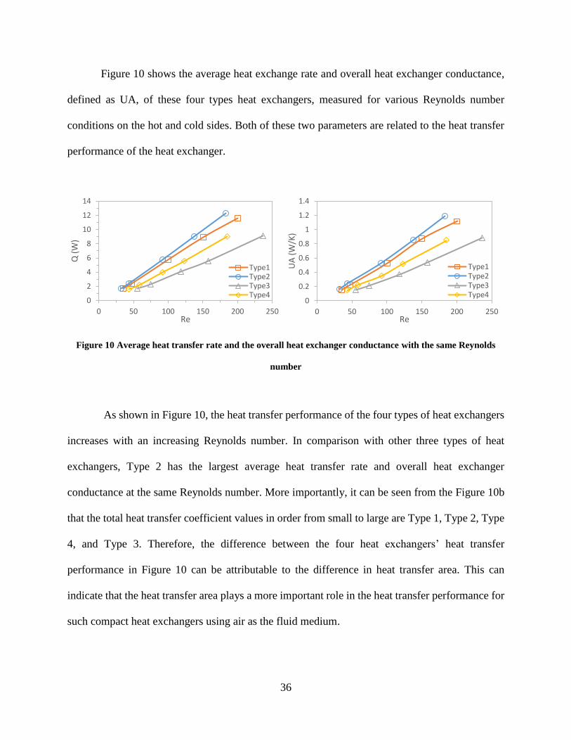
Figure 21 Comparison of hydraulic radius for different channels......................................... 50
Figure 22 Comparison of surface roughness for different channels ...................................... 50
Figure 23 Comparison of pressure drops with the same Reynolds number ......................... 52
Figure 24 Comparison of the Fanning friction factors with the same Reynolds number .... 53

viii
Acknowledgments
I would have great and sincere thanks to my advisor, Dr. Minking Chyu for his patience,
generousness and invaluable guidance throughout my study and research. Our conversation has
always been friendly and meaningful, and it will benefit my life.
I would also thank my committee members Dr. Qing-Ming Wang and Dr. Patrick
Smolinski for their time to make this thesis better.
I am also extremely grateful to my excellent upper class students in my research group:
Zheng Min, Sarwesh Parbat. Without their help and encouragement in this research, I would have
never accomplished my research.
Finally, I would like to thank my family and my girlfriend for their unconditional support
and love.

ix
Nomenclature
𝐴 Heat transfer area
𝐴𝑐ℎ Cross-sectional area of flow channel
𝐴𝑓 Free flow area
𝐶 Fluid heat transfer capacity rates
𝐶𝑝 Specific heat
𝐶𝑟 Heat capacity-rate ratio
𝐷ℎ Hydraulic diameter
E Joint efficiency
𝑓 Fanning friction factor
𝑓𝐷 Darcy or Moody's friction factor
ℎ Convective heat transfer coefficient
𝑘 Thermal conductivity of the fluid
𝑘𝑠 Thermal conductivity
𝐿 Actual length of the channel
�̇� Mass flow rate
𝑁𝑐ℎ Number of channels on one side
𝑁𝑢 Nusselt number
NTU Number of transfer units
𝑃 Internal design pressure
𝑃𝑐ℎ Cross-sectional perimeter of the flow channel

x
∆𝑝 Pressure drop
𝑄 Heat exchange rate
𝑄𝑙𝑜𝑠𝑠 Heat loss
𝑄𝑚 Average heat exchange rate
𝑅 Channel radius
𝑅𝑎 Arithmetical deviation of profile
𝑅ℎ Hydraulic radius
𝑅𝑚 Mean radius
𝑅𝑒 Reynolds number
𝑆 Maximum allowable stress
𝑇 Fluid temperature
∆𝑇𝑚 Logarithmic mean temperature difference
𝑡 Solid wall thickness
𝑈 Overall heat transfer coefficient
𝑈𝐴 Overall heat exchanger conductance
𝑉 Heat exchanger volume
𝑣 Fluid velocity
𝛽 Heat transfer surface area density
𝜀 Heat exchanger effectiveness
𝜌 Fluid density
𝜇 Dynamic viscosity
Subscripts
c Cold fluid

xi
h Hot fluid
in Inlet
out Outlet
max maximum
min Minimum
circle Circular channel
semicircle Semicircular channel

1
1.0 Introduction
1.1 Project Background
Heat exchanger is a device used to transfer the heat of high temperature fluid to low
temperature fluid. It is a heat transfer device widely used in power systems, chemical processing,
manufacturing industries and other industrial sectors, or as air conditioners, refrigerators and
radiators indispensable in modern life. Although the shell-and-tube type heat exchanger is the most
widely used heat exchanger, due to its large volume, it is inferior to some plate heat exchangers
and new high-efficiency heat exchangers in terms of compact structure, heat exchanger
effectiveness and metal consumption per unit heat transfer area. Therefore, shell-and-tube heat
exchangers have gradually been replaced by other more efficient and compact heat exchangers. A
compact heat exchanger with a large ratio of heat transfer surface area per unit volume can reduce
the installation space, weight, energy requirements and costs, thus improving plant layout and
processing conditions and operating efficiency. For the definition of compact heat exchangers,
several researchers have proposed different standards for compact heat exchangers. D. A. Reay et
al. [1] proposed that compact heat exchangers are defined as the units with a surface area density
larger than 700 m2/m3 when operating in gas streams, or larger than 300 m2/m3 when operating in
the liquid or two-phase streams. However, some heat exchangers with a surface area density larger
than 200 m2/m3 can also be considered as compact heat exchangers. Mehendale et al. [2] classified
the heat exchangers with hydraulic diameters from 1mm to 6mm as compact heat exchangers. In
summary, the compact heat exchanger is a general term for the heat exchanger with a large ratio
of heat transfer surface area to volume.

2
Printed Circuit Heat Exchanger (PCHE) is one type of compact heat exchanger, which is
classified as a plate heat exchanger, developed as a replacement for shell-and-tube heat exchangers.
Because the compactness of this heat exchanger ranges from 200 to 5000 m2/m3 according to
different structural designs[3], which is usually larger than traditional shell-and-tube heat
exchangers[1], meeting the expectations of high efficiency and compactness. The manufacturing
method of PCHE is mainly to etch out the fluid channels on one side of each plate by chemical
etching, and then stack the etched plates in the required order. Finally, by employing the diffusion
bonding method, the contact surfaces between adjacent plates are fused with each other to form a
strong and compact heat exchanger core. The flow channel characteristics of PCHE are the main
factors affecting the heat transfer and flow resistance characteristics of heat exchangers. The layout
of the flow channel mainly can be designed as parallel-flow, counter-flow and cross-flow. Among
them, cross-flow is the most common flow arrangement, because it greatly simplifies the design
of the header at the inlet and outlet of each fluid[3]. Currently, the types of PCHE channels include
the straight, zigzag, wavy or airfoil. Among them, the straight shape is the simplest flow channel
structure of PCHE. The structural parameters of the PCHE flow channel include cross-sectional
shape, hydraulic diameter, and channel interval. The cross-section of the PCHE channel is usually
a semicircular shape with a diameter of 0.5 to 2 mm. The longitudinal interval between the
channels is limited by the thickness of the individually assembled plates, which is typically greater
than 1.6 mm[3]. Therefore, in actual manufacturing or simulation research, many researchers have
set the longitudinal interval to 1.6 mm or more [4–7]. The channel pitch is selected according to
the performance requirements and operating conditions. At present, the heat exchanger
effectiveness of PCHE can achieve higher than 97%, and the maximum working temperature and
pressure can reach 1000 ℃ and 500 bars, respectively[8]. The main material for manufacturing

3
PCHE is 300 series austenitic stainless steel, such as SS304, SS316, SS316L. Various other
feasible metals include 22 chromium duplex metals, copper nickel, nickel alloys, and titanium[9].
Because PCHE adopts diffusion bonding to stack the etched flat metal plates into the heat
exchanger core, improving the stability of the weld seam, which makes it meet the requirements
of safety and reliability under high-pressure conditions. Due to the high heat exchanger
effectiveness provided by such advanced heat exchanger design under high pressure and limited
space conditions, PCHE has been applied in the fields of liquefied natural gas industry, aerospace,
chemical processing, nuclear power and solar power generation.
Photochemical machining (PCM) and diffusion bonding are the two main techniques used
to fabricate PCHE. The PCM is a chemical milling process, normally performed in a series of eight
steps: cutting, cleaning, coating, photo-tooling, exposing, developing, photo-etching and
stripping[10]. Due to the effect of the strong chemical etchants, the average surface roughness of
the channels etched on the metal plate is less than a micrometer[11]. However, the disadvantage
of PCM is that the etchant will not only corrode the metal downwards, but also corrode
sideways[12], which limits the design of the channel cross-sectional shape. More importantly, the
strong chemical etchants are very dangerous to workers[13]. For diffusion bonding, this is a solid-
state joining process where two flat surfaces are bonded with high pressure at an elevated
temperature[14]. For example, Mylavarapu et al.[15] fabricated two heat exchangers by diffusion
bonding. During the manufacturing process, the metal parts were heated to about 1120 ℃ and kept
bonded for four hours under the pressure of 6.8 to 10.2 MPa. Considering the operation conditions
of these two techniques, it is obvious that in addition to industrial production, the manufacture of
PCHE is difficult and might be dangerous in an academic laboratory setting.

4
In recent years, direct metal laser sintering (DMLS), as one of the most promising metallic
additive manufacturing technologies, has gradually been applied to various fields. This technology
mainly uses laser beam to sinter metal powder into a solid part layer by layer, which can directly
produce complex features according to CAD model, leading to a significant reduction in time[16-
17]. Compared with traditional manufacturing technologies, DMLS has the advantages of simple
production steps, high flexibility of product design and the possibility to manufacture metal parts
with high dimensional accuracy and geometric complexity[18-19]. In addition, the entire
manufacturing process is automatic, which greatly benefits the fabrication process[20]. Hence,
DMLS has great application potential in many fields such as biomedical, automotive, energy,
consumer goods and aerospace[21]. For compact heat exchangers manufacturing, using the DMLS
method will not only simplify the fabrication steps but will also provide the possibility of designing
complex channel structures. Moreover, DMLS method allows the heat exchanger to be
manufactured directly as an integrated device, which can eliminate the difficulties for assembly.
Therefore, it is worth considering utilizing the DMLS method instead of the traditional PCHE
manufacturing method to construct compact heat exchangers with the similar structure.
1.2 Literature Review
Among the previous studies on compact heat exchangers, Reay et al. [1] summarized a
number of compact heat exchangers with different types. Compared with traditional shell and tube
heat exchangers, their area density is greater than 200 m2/m3, which greatly improved the
efficiency and reduced the volume and weight of the heat exchanger. The particular PCHE cited
in [1] played a significant role in reducing the cost of a heat pump system.

5
Yoon et al.[22] developed a cross-flow PCHE analysis code to evaluate the size and cost
of the heat exchanger by utilizing MATLAB software. The information provided by this code can
be used to optimize the design of advanced small modular reactors (SMRs) systems.
Tsuzuki et al.[6] carried out simulations using FLUENT CFD-based software to compare
the PCHE with discontinuous S-shape flow channel configuration to the conventional continuous
zigzag configuration. Their results suggested that the pressure drop in S-shape flow channels was
one-fifth that in zigzag channels, while the thermal performance was about equal. The reverse
flows and eddies occurring around bend corners of zigzag flow channels are the main causes for
the increased pressure drop.
Wang et al.[23] conducted a numerical simulation to investigate the thermal-hydraulic
performance of the sinusoidal channel PCHE. They found that the overall Nusselt number was
enhanced by 7.4% to 13.9%, while the global Fanning friction factor increased by 10.9% to 16.7%
compared to the straight channel PCHE. Their results suggested that under the condition of the
same length, the heat transfer capacity improvement of sinusoidal channel compared to the straight
channel was attributable to the higher level of local turbulence intensity around the curved corners.
Lee et al.[24] performed a comparative study on the performance of a zigzag PCHE with
various channel cross-sectional shapes (semicircular, circular, rectangular and trapezoidal) using
CFD simulation. They reported that the PCHE with a rectangular channel cross section had the
highest effectiveness, while the PCHE with a circular channel cross section had the lowest
effectiveness among the four different shapes. However, in terms of friction factors, the circular
channel had the smallest friction factor, suggesting the flow resistance in the channel is the lowest.
Berbish et al.[25] performed an experimental study on forced convection heat transfer and
pressure drop characteristics of airflow in a horizontal semicircular duct to obtain empirical

6
correlations for the heat transfer coefficient and friction factor as a function of the Reynolds
number. By comparing with the empirical correlations for straight circular duct proposed by
Renolds[26] and Blasius[27], they found that both the Nusselt number and the friction factor of
the semicircular tube were slightly higher, due mainly to the effects of the sharp edges of the
semicircular duct that distorted the axial velocity profile.
Kim et al.[28] performed a numerical analysis using CFD simulation. They found that the
numerical simulation of the traditional zigzag PCHE differed from the experimental data by about
10%. They also studied a PCHE model filled with airfoil-shaped flow channels in comparison with
the typical zigzag flow channels. Their results suggested that for a given heat exchange rate per
unit volume, the pressure drop in the airfoil-based PCHE was only one-twentieth of that in the
traditional zigzag-channeled PCHE. The plausible reason is that the airfoil shape suppresses the
separation of flow, which occurred at the corners of the zigzag channels, thereby reducing the
pressure loss.
Seo et al.[29] conducted a study on heat transfer and pressure drop characteristics in
straight channel of PCHE with different flow arrangements. They found that the heat transfer
performance of the counter-flow PCHE was 10% to 15% higher than that of the parallel-flow
PCHE.
Kim et al. [30] conducted a study on the thermal-hydraulic performance of the PCHE using
a helium test facility. They purposed two empirical correlations for the average Fanning friction
factor and average Nusselt number in laminar flow region. Each empirical correlation consisted of
a constant term and a functional term. The constant term was related to the geometrical
characteristics of the straight portion of the PCHE channel, such as the channel cross-sectional

7
shape. The functional term was related linearly to the Reynolds number due to the form loss at
sharp elbows in the zigzag channel.
For the recent research on channels or heat exchangers manufactured through DMLS
method, Utilizing CT scan, Snyder et al.[31] conducted a study on the influence of DMLS build
direction on the heat transfer coefficient and pressure loss in small-scale channels. They indicated
that the channels with vertically build direction had the lowest friction factor, while the channels
with diagonally build direction had the highest friction factor. However, large differences in
friction factors caused by build directions did not produce similar differences in Nusselt numbers.
Somewhat unexpectedly, the heat transfer performance of these channels was almost the same.
Kirsch et al.[32] conducted a study on the heat transfer and pressure loss performance of wavy
channels manufactured through DMLS. They found that the wavy channels improved heat transfer but
also introduced higher pressure loss compared to the straight channels. Among them, short-wavelength
channels introduced high pressure losses without noticeable improvement in heat transfer, while long-
wavelength channels provided good heat transfer performance with a less penalty in pressure drop.
Stimpson et al.[33] carried out experiments for roughness effects on flow resistance and heat
transfer in DMLS manufactured channels. They manufactured ten different coupons with
rectangular channels, measured the surface roughness levels through CT scans, and then compared
the friction factor and heat transfer performance of these coupons. Results indicated that compared
with the smooth channels, the friction factors of these channels had been significantly increased,
causing higher pressure losses. Although the roughness improved the heat transfer coefficient to
some extent, the increase in heat transfer coefficient did not match with the increase in the friction
factor, as it.
Zhang et al.[34] manufactured a compact gas-to-gas heat exchanger through DMLS and
tested it at 600 ℃ with 450 kPa inlet pressure. The maximum heat duty and heat transfer density

8
of this heat exchanger are 2.78 kW and 10 kW/kg, respectively. This work demonstrated the
possibility of using DMLS to fabricate compact heat exchangers

9
2.0 Theoretical Analysis and Geometric Design
2.1 Theoretical Analysis
2.1.1 Convection Heat Transfer Theory Analysis
For a compact heat exchanger like PCHE, it can be classified as a surface type heat transfer
device. Inside a heat exchanger, the two fluids are separated by a solid wall. Its heat transfer
principle is that the hot fluid first transfers heat to the wall surface through convective heat transfer.
After conducting in the solid wall, the heat is then transferred to the cold fluid from another solid
wall surface through convective heat transfer. Convective heat transfer can refer to the transfer of
heat from a fluid to a solid wall, which is driven by the movement of the fluid. There are many
factors affecting convection heat transfer, which can be summarized as follows [35]:
(1) Causes of fluid flow
According to different flow causes, convective heat transfer can be divided into natural
convective heat transfer and forced convective heat transfer. Natural convection heat transfer is
due to the uneven distribution of temperature or concentration in the flow field, which makes the
fluid density distribution vary greatly. Consequently, the fluid will flow naturally and exchange
heat with the solid wall under the influence of temperature difference. In forced convective heat
transfer, the fluid is forced to flow over and exchange heat with the surface of solid wall by external
means such as pumps, fans, suction devices or others. When the causes of fluid flow are different,
the velocity and state distribution of the fluid will be different, which will lead to different heat
transfer effects.

10
(2) Phase transition of fluid
In the process of heat exchange, if the fluid has no phase change, its heat exchange is
realized through the change of the sensible heat of the fluid. In another case, if the fluid undergoes
a phase change during the heat exchange process, such as evaporation or condensation, the change
in the latent heat of the fluid at this time will have a greater impact on the heat exchange.
(3) Flow state of fluid
When the fluid is viscous, its flow state can be divided into laminar state or turbulent state.
In laminar flow, the fluid mainly performs regular layered movements in the mainstream direction,
the flow is relatively stable and no mixing occurs between the fluid layers, and the transmission of
momentum and energy mainly depends on the diffusion of molecules; In laminar flow, in addition
to the fluid moving in the mainstream direction, there is also a turbulent and random vortex
movement of the fluid micelles. At this time, the transmission of momentum and energy occurs
not only in the mainstream direction, but also in a direction perpendicular to the mainstream.
Therefore, under the same conditions, the heat transfer intensity during fluid turbulence is stronger
than that during laminar flow.
(4) Physical properties of fluid
The physical properties of the fluid, such as the density, dynamic viscosity, thermal
conductivity, and constant pressure heat capacity, all have an effect on the velocity and temperature
distribution of the fluid in the flow field, which will affect the convective heat transfer strength of
the fluid.
(5) Geometric factors of heat transfer surface
The surface where the fluid is in contact with the heat exchanger and exchanges heat may
be referred to as the heat exchange surface. The size, shape, roughness, and arrangement of the

11
heat transfer surface will affect the convective heat transfer between the fluid and the heat transfer
surface. Therefore, in the case of designing different types of heat exchangers, these factors need
specific analysis and research.
As can be seen from the above, there are many factors that affect convective heat transfer,
so the methods for improving the heat transfer performance of heat exchangers will vary according
to different factors. For different manufacturing and operating conditions, there are different
suitable methods to enhance the heat transfer performance of heat exchangers. For PCHE-type
compact heat exchangers, the internal heat exchange is mainly through forced convective heat
exchange of fluids in microchannels. Therefore, when researching how to optimize such heat
exchangers, it is mainly to adopt a technique to increase the convective heat transfer coefficient
and reduce the thermal resistance in order to achieve an increase in the heat exchange capacity of
the heat exchanger without causing excessive pressure drop in the fluid[36]. According to the
influencing factors of convective heat transfer, the way to strengthen the heat transfer process in
the heat exchanger can be:
(1) Increase the total heat transfer area in the heat exchanger
(2) Increase the average heat transfer temperature difference between cold and hot flow
(3) Increase the heat transfer coefficient
In general, increasing the total heat transfer area of a heat exchanger to improve heat
transfer is a direct and effective method. However, for the traditional shell-and-tube heat exchanger,
increasing the total heat transfer area usually results in a greater weight and volume of the heat
exchanger, which leads to an increase in manufacturing cost and space occupation. The ideal
design solution is to increase the heat transfer area per unit volume of the heat exchanger to
increase its compactness while ensuring that the volume of the heat exchanger is unchanged. For

12
compact heat exchangers similar to PCHE, the heat transfer area per unit volume of the heat
exchanger can be increased by increasing the number of channels inside the heat exchanger.
There are two methods used to change the average temperature difference between hot and
cold fluids. One is to change the form and configuration of the flow arrangement inside the heat
exchanger, such as changing the parallel-flow arrangement to a counter-flow arrangement or a
crossflow flow arrangement, or using another suitable flow arrangement design. Under the same
operating conditions, the average temperature difference between the hot and cold fluid inside the
heat exchanger with different flow arrangement forms and configurations will be different; the
other is to change the temperature difference between the hot and cold fluid inlet and outlet.
However, in practical applications, limited by factors such as operating conditions and physical
properties of the heated material, the selection range of the temperature of the hot and cold fluid
at the inlet and outlet of the heat exchanger is usually not very abundant, which restricts the use of
the second method.
The heat transfer coefficient in the heat exchanger is related to many factors such as the
cause of fluid flow, the phase transition of the fluid, the physical properties of the fluid, and the
geometric factors of the heat transfer surface. Theoretically, methods such as increasing the flow
velocity of the fluid, destroying the fluid boundary layer, and designing the cylindrical bodies
inside the heat exchanger that fluid flows around can improve the convective heat transfer
coefficient[37]. For compact heat exchangers similar to PCHE, the heat transfer in the channel can
be enhanced by changing the traditional straight channel inside the heat exchanger to a curved S-
shaped channel. Its mechanism for enhancing heat exchange is that the curved microchannels will
not only extend the flow path of the fluid in the channel but also damage the flow boundary layer
and hinder its development, thereby achieving the purpose of enhancing heat transfer [38].

13
In this study, the methods of increasing the heat transfer area and changing the channel
structure will be used mainly to improve the heat transfer of the heat exchanger.
2.1.2 Theoretical Calculation Formula
The two key indicators for measuring the performance of a heat exchanger are the heat
transfer performance and pressure drop of the fluid. The heat transfer performance of heat
exchangers is usually analyzed using the logarithmic mean temperature difference (LMTD)
method or the effective number of transfer unit (ε-NTU) method. The LMTD method is convenient
for determining the overall heat transfer coefficient based on the measured inlet and outlet fluid
temperatures. The ε-NTU method is convenient for predicting the outlet fluid temperature when
the heat transfer coefficient and inlet temperature are known.
The heat exchange rate of heat and cold flow in the heat exchanger can be obtained by the
following formula:
𝑄ℎ = �̇�ℎ𝐶𝑝,ℎ(𝑇ℎ,𝑖𝑛 − 𝑇ℎ,𝑜𝑢𝑡) (2 − 1)
𝑄𝑐 = �̇�𝑐𝐶𝑝,𝑐(𝑇𝑐,𝑖𝑛 − 𝑇𝑐,𝑜𝑢𝑡) (2 − 2)
where the subscripts h and c represent hot and cold fluids, and the subscripts in and out designate
the fluid inlet and outlet conditions.
The fluid heat transfer capacity rates are defined as:
𝐶ℎ = �̇�ℎ𝐶𝑝,ℎ (2 − 3)
𝐶𝑐 = �̇�𝑐𝐶𝑝,𝑐 (2 − 4)
𝐶𝑚𝑖𝑛 = min(𝐶ℎ, 𝐶𝑐) (2 − 5)
𝐶𝑟 =𝐶𝑚𝑖𝑛
𝐶𝑚𝑎𝑥
(2 − 6)

14
where 𝐶ℎ and 𝐶𝑐 are the heat transfer rates of the hot and cold fluids, respectively. 𝐶𝑚𝑖𝑛 is the
minimum fluid capacity rate, and 𝐶𝑚𝑎𝑥 is the maximum fluid capacity rate. 𝐶𝑟 is the heat capacity-
rate ratio.
The heat transfer performance of the heat exchanger can be measured by analyzing the heat
exchanger effectiveness and the overall heat transfer coefficient of the heat exchanger. The
effectiveness 𝜀 of the heat exchanger is the ratio of the actual heat transfer in the heat exchanger
to the maximum heat transfer that can be achieved physically, which is defined as:
𝜀 =𝑄ℎ
𝑄𝑚𝑎𝑥=
𝐶ℎ(𝑇ℎ,𝑖𝑛 − 𝑇ℎ,𝑜𝑢𝑡)
𝐶𝑚𝑖𝑛(𝑇ℎ,𝑖𝑛 − 𝑇𝑐,𝑖𝑛)(2 − 7)
The overall heat transfer coefficient of the heat exchanger depends on the conductivity of
the heat transfer wall separating the two fluids and the convection coefficient on both sides of the
heat transfer wall.
The average heat exchange rate 𝑄𝑚 of the heat exchanger, the overall heat transfer
coefficient U and the overall heat exchanger conductance UA value [29] can be obtained by the
LMTD method, and they may be computed from the following equation:
𝑄𝑚 =𝑄h + 𝑄𝑐
2(2 − 8)
𝑈 =𝑄𝑚
𝐴∆𝑇𝑚
(2 − 9)
𝑈𝐴 =𝑄𝑚
∆𝑇𝑚
(2 − 10)
where A is the heat transfer area, ∆𝑇𝑚 is the logarithmic mean temperature difference. The mean
temperature difference as defined is the logarithmic mean value as:
∆𝑇𝑚 =∆𝑇1 − ∆𝑇2
ln (∆𝑇1
∆𝑇2)
(2 − 11)

15
With
∆𝑇1 = 𝑇ℎ,𝑖𝑛 − 𝑇𝑐,𝑜𝑢𝑡 (2 − 12)
And
∆𝑇2 = 𝑇ℎ,𝑜𝑢𝑡 − 𝑇𝑐,𝑖𝑛 (2 − 13)
The heat loss of the heat exchanger is mainly due to the fact that the heat exchanger cannot
be completely insulated in actual operation, so that in addition to most of the heat obtained from
the heat source is transferred to the cold flow, part of the heat will be transferred to the surrounding.
The heat loss 𝑄𝑙𝑜𝑠𝑠 can be calculated by the following formula:
𝑄𝑙𝑜𝑠𝑠(%) =|𝑄ℎ − 𝑄𝑐|
𝑄ℎ
(2 − 14)
In addition to the total heat transfer coefficient U and overall heat exchanger conductance,
UA value, the Nusselt number Nu can be used as a parameter to measure the convective heat
transfer performance in the channel. The Nusselt number represents the ratio of the conductive
resistance to the convective thermal resistance of the working flow in the channel, which is defined
as:
𝑁𝑢 =ℎ𝐷ℎ
𝑘(2 − 15)
where h is the convective heat transfer coefficient in the channel depending on the fluid properties,
flow velocity and channel geometric characteristics, k is the thermal conductivity of the fluid in
the channel, and is the hydraulic diameter of the channel. The relationship between the convection
heat transfer coefficient h and the total heat transfer coefficient U is:
1
𝑈𝐴=
1
ℎℎ𝐴ℎ+
𝑡
𝑘𝑠𝐴+
1
ℎ𝑐𝐴𝑐
(2 − 16)
𝐴 = min(𝐴ℎ, 𝐴𝑐) (2 − 17)

16
where t is the solid wall thickness between the hot and cold channels, 𝑘𝑠 is the thermal conductivity
of the solid material, 𝐴ℎ and 𝐴𝑐 are the heat transfer surface area on the hot fluid side and the cold
fluid side, respectively. The value of 𝐴 is usually the maximum value between 𝐴ℎ and 𝐴𝑐.
The hydraulic diameter 𝐷ℎ, the Reynolds number 𝑅𝑒, the free flow area 𝐴𝑓 and the heat
transfer area 𝐴 on one side of the heat exchanger are calculated by the following relationship:
𝐷ℎ =4𝐴𝑐ℎ
𝑃𝑐ℎ
(2 − 18)
𝑅𝑒 =𝜌𝑣𝐷ℎ
𝜇=
�̇�𝐷ℎ
𝜇𝐴𝑓
(2 − 19)
𝐴𝑓 = 𝑁𝑐ℎ𝐴𝑐ℎ (2 − 20)
𝐴 = 𝑁𝑐ℎ𝐿𝑃𝑐ℎ (2 − 21)
where 𝐴𝑐ℎ is the cross-sectional area of each channel, 𝑃𝑐ℎ is the cross-sectional perimeter of the
flow channel, 𝑁𝑐ℎ is the number of channels on one side, and 𝐿 is the actual length of the channel.
The heat transfer surface area density 𝛽 is defined as the ratio of the heat transfer area on
one side to the volume occupied by the flow channel on this side, which can be calculated by the
following formula:
𝛽 =𝐴ℎ
𝑉ℎ 𝑜𝑟
𝐴𝑐
𝑉𝑐
(2 − 22)
where 𝑉ℎ and 𝑉𝑐 are the volumes individually occupied by the hot and cold fluid side heat transfer
surfaces.
When measuring the performance of a heat exchanger, in addition to the thermodynamic
performance, the pressure drop between the fluid at the inlet and the outlet of the heat exchanger
is also worth considering. The pressure drop for the heat exchanger can be obtained from:
∆𝑝 = 𝑓4𝐿
𝐷ℎ
1
2𝜌𝑣2 (2 − 23)

17
where f is the Fanning friction factor, which is defined based on the equivalent shear force per unit
friction area in the flow direction, and is usually expressed by the relationship with the Reynolds
number. It is related to the Reynolds number of the fluid, the surface roughness of the flow channel
and the geometric characteristics of the heat exchanger channel. An increase in the Fanning friction
factor indicates an increase in the flow resistance of the fluid. Therefore, f can be calculated from:
𝑓 =2𝜏𝑠
𝜌𝑣2=
𝑃𝑖𝑛 − 𝑃𝑜𝑢𝑡
2𝜌𝑣2(
𝐷ℎ
𝐿) (2 − 24)
where 𝜏𝑠 is the shear stress on the solid wall of the channel, Pin is the fluid inlet pressure, Pout is
the fluid outlet pressure, ρ is the fluid density, and v is the flow velocity.
In addition, Darcy or Moody's friction factor 𝑓𝐷 can also be used to represent the flow
resistance in the channel, and its calculation relationship with the Fanning friction factor is:
𝑓𝐷 = 4𝑓 (2 − 25)
2.2 Compact Heat Exchangers Design
2.2.1 Flow Arrangement
For the design of compact heat exchangers, the form and configuration of the flow
arrangement need to be carefully considered. Different flow arrangement designs will make the
temperature distribution inside the heat exchanger different, which will affect the effectiveness of
the heat exchanger. At the same time, it has different design and manufacturing difficulties.
Therefore, when designing a compact heat exchanger, it is necessary to select a suitable flow
arrangement form and configuration according to the desired heat exchanger effectiveness and

18
manufacturing difficulty. Depending on their form and configuration in the heat exchanger, there
are three main types of flow arrangements, and they are:
(1) Counter-flow
In this type of flow arrangement, the two fluids enter the heat exchanger from opposite
ends. Each channel in the heat exchanger is parallel to each other.
(2) Parallel-flow
In this type of flow arrangement, the two fluids enter the exchanger at the same end and
flow parallel to each other. Each channel in the heat exchanger is also parallel to each other.
(3) Cross-flow
In this type of flow arrangement, the hot and cold fluids typically pass through the heat
exchanger perpendicular to each other. The channels of the same fluid are parallel to each other,
while the hot and cold channels are roughly perpendicular to each other.
For a single-pass heat exchanger, its heat exchanger effectiveness can be calculated
theoretically by the ε-NTU method. The Number of Transfer Units (NTU) for the exchanger is
defined as:
NTU =𝑈𝐴
𝐶𝑚𝑖𝑛
(2 − 26)
After obtaining the value of NTU, combined with the heat capacity-rate ratio obtained by
Equation(6), the theoretical value of the heat exchanger effectiveness can be obtained by the ε-
NTU method. For a single pass heat exchanger in the parallel-flow arrangement, the effectiveness
is expressed as[3]:
𝜀 =1 − exp[−NTU(1 + 𝐶𝑟)]
1 + 𝐶𝑟
(2 − 27)

19
For a single pass heat exchanger in the counter-flow arrangement, the effectiveness is
defined as:
𝜀 =1 − exp[−NTU(1 + 𝐶𝑟)]
1 + 𝐶𝑟 exp[−NTU(1 − 𝐶𝑟)](2 − 28)
Similarly, for a single pass heat exchanger in the cross-flow arrangement, the effectiveness
can be defined as:
𝜀 =1
𝐶𝑟
{1 − exp[−𝐶𝑟 + 𝐶𝑟 exp(−NTU)]} (2 − 29)
Under the same thermodynamic conditions, the counter-flow arrangement of heat
exchanger usually has the highest heat transfer efficiency[39], the reason is that its average
temperature difference along any unit length is the highest. In contrast, the parallel-flow
arrangement usually has the lowest heat transfer efficiency, while cross-flow arrangement has
intermediate thermodynamic performance. The temperature distribution diagram of the heat
exchanger under different flow channel arrangements is shown in Figure 1.
Figure 1 Typical temperature distributions in heat exchangers

20
However, although the counter-flow arrangement provides the highest heat or cold
recovery for the heat exchanger, it must separate the fluid at each end of the heat exchanger and
then re-aggregate the same type of fluid. As a result, the geometric design of the header distributor
channel is complicated, resulting in design and manufacturing difficulties for compact heat
exchangers with counter-flow arrangement[3].
For compact heat exchangers, cross-flow is the most common flow arrangement[3]. While
it has high heat exchange performance, there is no need to separate different fluids at the inlet and
outlet of the heat exchanger like a counter-flow arrangement, which greatly simplifies the
geometric design of the header distributor channel and reduces manufacturing costs.
In addition to the above three main process arrangement methods, the combination any of
these flow configurations will also be considered in actual design. For example, cross-counter flow
arrangement is a combination of cross-flow and counter-flow arrangement. In this arrangement,
one fluid flows in a straight path, while the second fluid follows a zigzag path perpendicular to the
first flow. While negotiating the zigzag path, the flow directions of the two fluids in the straight
part are parallel and opposite to each other. Therefore, this flow arrangement can be regarded as a
global counter-flow, while it remains locally as a cross-flow.
2.2.2 Channel Cross-sectional Shape
When a compact heat exchanger similar to PCHE is manufactured using the DMLS method,
the design of the cross-sectional shape of the flow passage is not restricted. Therefore, in addition
to manufacturing semi-circular channels according to the standard PCHE, other channel cross-
sectional shapes can also be selected to improve the performance of heat exchangers based on the
flow and heat transfer characteristics of fluids in the channels of different cross-sectional shapes.

21
Bahman et al. [3] provide a comparison of some common channel cross-sectional shapes with the
same hydraulic diameter when the fluid in the channel is laminar, which is shown in Table 1.
Table 1 Comparison of laminar-flow solutions for different cross-sectional shape
Cross section Nu fRe
Triangle 2.35 13.33
Circle 3.66 16.0
Square 2.89 14.2
Rectangle (b/a=4) 4.65 18.3
Rectangle (b/a=8) 5.95 20.5
Rectangle (b/a=∞) 7.54 24.0
Note that a and b represent the width and length of the rectangle, respectively. The above
data applies to the case where 𝐿/4𝑅ℎ > 100, where 𝐿 and 𝑅ℎ represent the length and hydraulic
radius of the channel, respectively. It can be seen from the Table 1 that as the cross section of the
channel gradually becomes flat, the Nusselt number increases, which means that the convection
heat transfer capacity of the channel is enhanced. The main reason is that the rectangular cross-
section of aspect ratio (b/a) is flat in shape and usually provides the smaller frontal area, which
increases the Reynolds number in the channel at the same flow. As a result, convective heat transfer
is enhanced, which is reflected numerically as an increase in Nusselt number. Simultaneously, the
friction factor also increases, mainly because the perimeter of the section increases as the shape of
the section becomes flatter. When these channels have the same roughness, the longer the
perimeter of the channel cross-section, the greater the frictional force experienced by the fluid. In

22
addition, stress concentration also occurs at the corners of the cross section of the channel, which
also results in increased resistance on the fluid. In addition, stress concentration will occurs at the
corners of the cross section of the channel, which also results in an increase in the friction factor
in the channel.
Lee et al. [24] compared the heat transfer performance and friction coefficient of
semicircular and circular cross-section channels with the same hydraulic diameter using ANSYS
software. The simulation results show that the semicircular cross-section channel is about 4.5%
higher in heat transfer effectiveness and 5.3% higher in friction factor than the circular cross-
section channel. This shows that under the same number of channels and operating conditions,
although the heat transfer characteristics of semicircular channels are better than circular channels,
the pressure drop will be larger due to the larger friction factor. Therefore, a trade-off needs to be
made between efficiency and coefficient of friction when choosing the shape of the channel cross
section.
With the same hydraulic diameter, the ratio of the cross-sectional area of the circular cross-
section channel to the semi-circular cross-section channel is as follows:
𝐴𝑐𝑖𝑟𝑐𝑙𝑒
𝐴𝑠𝑒𝑚𝑖𝑐𝑖𝑟𝑐𝑙𝑒=
2𝜋2
(2 + 𝜋)2= 0.746 < 1 (2 − 30)
For manufacturing compact heat exchangers like PCHE with a fixed volume, the smaller
cross-sectional area of the circular cross-section channels means that a larger number of channels
with a circular cross-section can be arranged when the cross-section of the heat exchanger is fixed.
This makes the overall heat exchange area of the heat exchanger larger, thereby increasing the heat
exchange capacity of the heat exchanger. More importantly, the advantage of a smaller the friction
factor for circular cross-section channel can be utilized to reduce the fluid pressure drop. Therefore,

23
when manufacturing compact heat exchangers, it may be considered to use a circular cross-section
channel instead of a semicircular cross-section channel.
In addition, the use of rectangular cross-section channels with rounded corners can also be
considered. When taking advantage of the good heat transfer characteristics of rectangular cross-
section channels, the rounded corners can reduce the friction factor to a certain extent. In
conclusion, the design of the channel cross-sectional shape of the compact heat exchanger requires
a comprehensive consideration.
2.2.3 Wall Thickness between Channels
For the design of compact heat exchangers, after determining the flow arrangement and
cross-sectional shape of the heat exchanger channels, the solid wall thickness between each
channel needs to be considered.
The thickness of the wall is mainly determined by the maximum design pressure inside the
heat exchanger. According to the heat exchanger design part of ASEM[40] , the minimum wall
thickness calculation formula for circular channels is:
𝑡𝑚𝑖𝑛 =𝑃𝑅
𝑆𝐸 − 0.6𝑃(2 − 31)
where P is the internal design pressure, R is the channel radius, S is the maximum allowable stress
value of the material, and E is the joint efficiency.
For standard PCHE, the maximum pressure inside the channel during operation can be up
to 500 bars. The joint efficiency E is 1 for seamless channels. Because the compact heat exchanger
manufactured by using the DMLS method is integrated, no assembly is required. The material used
to manufacture compact heat exchangers can be stainless steel, such as SS316, due to its high

24
thermal conductivity and good corrosion resistance. In the range of -30 to 100 degrees Celsius, the
maximum allowable stress parameter of SS316 is 138MPA according to the part of ASEM about
the metric properties of various materials[41].

25
3.0 Research Description
3.1 Objective
The goal of this study was to investigate the feasibility of applying the DMLS method to
construct compact heat exchangers similar to PCHE. Since there is no design limitation of the
geometric structure when manufacturing metal objects by the DMLS method, it is possible to get
rid of the constraints caused by the original manufacturing method of PCHE, and to consider the
employing different channel cross-sectional shape, structure and the interval to improve the
performance of the manufactured compact heat exchangers. However, the use of the DMLS
method to introduce metal objects introduces a degree of change in surface roughness and
geometric characteristics. However, metal objects manufactured by the DMLS method have a
certain degree of surface roughness. Therefore, the surface roughness of the channel and its
influence on the flow resistance also need to be explored.
3.2 Tasks
The first step of the task was to design and build a PCHE-like compact heat exchanger
models based on typical PCHE design data. Then design and build models of three other types of
heat exchangers, which have the same volume and the same hydraulic diameter as the first type of
heat exchanger, but with different flow channel characteristics. The second step of the task was to
manufacture the above-mentioned compact heat exchangers by the DMLS method, build and
26
assemble an experimental setup for measurement testing. The third step was to measure the heat
transfer performance and pressure drop of the four heat exchangers under the same conditions, and
then analyze the suitable method for designing the heat exchangers based on DMLS. The fourth
step was to measure the surfaces roughness of the channel in the heat exchangers, and discuss the
differences of the surface roughness when the build direction and channel cross-sectional shape
are different. The last task is to perform measurements of flow pressure losses in different channels.

27
4.0 Experimental Details
4.1 Compact Heat Exchangers Manufactured by DMLS Method
The heat exchangers in this study were manufactured using direct metal laser sintering
(DMLS) 3D printing method. The entire heat exchanger is integrated, while a typical PCHE is
formed by stacking multiple metal plates. The DMLS equipment used in this study was the
EOSM290 machine housed in the ANSYS Additive Manufacturing Research Laboratory at
University of Pittsburgh. Figure 2 shows the photograph of the compact heat exchangers made of
stainless SS316 by the DMLS method. These heat exchangers are in the cross-flow arrangement,
and the actual size of each heat exchanger is 25.4 × 70 × 90 mm.
Figure 2 Photograph of the compact heat exchangers

28
4.1.1 Four Types of Compact Heat Exchanger Designs
In this study, four different stainless compact heat exchangers were manufactured and
investigated. The hydraulic diameter of the channels in each heat exchanger is about 1 mm. Figure
3 shows the cross-sectional models and views of four types of compact heat exchangers
manufactured. Type 1 is the heat exchanger manufactured according to the structure of a standard
cross-flow PCHE heat exchanger. It has a straight channel structure and a semicircular channel
cross-sectional shape. The structural parameters of this Type 1 are set according to the typical
PCHE. The distance between the two channels in the vertical direction is 1.6mm. The distance in
the horizontal direction is the minimum wall thickness between channels at a design pressure of
500 bars.
Type 2 has the cross-sectional shape of the channel changed from semicircular to circular,
compared to Type 1. Under the same hydraulic diameter, the area of a circle is smaller than that of
a semicircle, thus more channels can be arranged on a fixed cross section of the heat exchanger,
which increases the total heat exchange area. In addition, since the circular channel has a smaller
friction factor than the semicircular channel[24], the pressure drop of the fluid passing through the
heat exchanger can be reduced by taking advantage of this characteristic. Type 2 also has straight
channels, and the interval between the channels is the minimum wall thickness calculated
according to the heat exchanger design part of ASEM[40]. Therefore, the channels are arranged to
the densest on the fixed-size cross section of the heat exchanger.

29
Figure 3 Four different types of compact heat exchangers investigated in this study
For Type 3, the cross-sectional shape of the channel remains circular. The straight channel
is changed to an S-shaped curved channel that is curved in the vertical direction, the purpose is to
increase the heat transfer coefficient of the channel, because curved microchannels can destroy the
flow boundary layer of the fluid and hinder its development. On the other hand, the cold flow
channel and the hot flow channel are staggered with each other, which increases the contact area
between each cold flow channel and hot flow channel. However, since the curved geometry
increases the volume occupied by each channel, the number of channels that can be arranged in a
fixed volume is reduced.
Type 4 decreases the bending curvature of the channels on the basis of Type 3 to reduce
the volume occupied by each channel, making it possible to arrange more channels under a fixed
heat exchanger volume. Type 4 is similar in structure to Type 3, the channels are curved, the cross-

30
sectional shape of the channels is circular, and the cold flow channels and hot flow channels inside
the heat exchanger are also interweaved. The specific design parameters of the four types of heat
exchangers are shown in Table 2.
Table 2 Design parameter table of compact heat exchanger
Type 1 Type 2 Type 3 Type 4
Channel cross
section shape semicircle circle circle circle
Geometric diameter
of the channel cross
section
1.6mm 1mm 1mm 1mm
Hydraulic diameter
of the channel cross
section
0.98mm 1mm 1mm 1mm
Number
of channels
Hot
side 180 258 150 192
Cold
side 180 258 150 192
Channel interval
in the horizontal
direction
2.1mm 1.5mm 2.6mm 1.5mm 4.1mm
Channel interval
in the vertical
direction
1.6mm 1.5mm 1.5mm 1.5mm
Channel
length
Hot
side 70mm 70mm 83mm 79mm
Cold
side 90mm 90mm 111mm 101mm
Angle
of the curved part 120° 60°
Radius
of the curved part 1.5mm 1.5mm
Dimensions of CHE
(H × W × L) 25.4×70×90mm 25.4×70×90mm 25.4×70×90mm 25.4×70×90mm

31
Figure 4 Total number of channels and total heat transfer area of compact heat exchanger
Figure 4 shows the total number of internal channels and heat transfer surface area per unit
volume of compact heat exchanger. As can be seen from the figure, Type 2 has the largest number
of channels and heat transfer area, while Type 3 has the least, and Type 1 and Type 4 occupy the
middle position.
4.1.2 Experiment Setup and Conditions
Figure 5 shows the model of the experimental setup test section. The framework of the test
section that house the AM made stainless steel PCHE is made of plexiglass. During the experiment,
the heat exchanger is installed in the middle of the test section, and the gaskets are placed on each
contact surface between the heat exchanger and the experimental setup. The four chambers formed
between the heat exchanger and the experimental device are the inlet and outlet chambers for cold
air and hot air, and there are three thermocouples inside each chamber to measure the average
temperature of the air. At the same time, two pressure gauges are connected to the test section to
record the pressure drop of cold air and hot air through the heat exchanger, respectively.
0
100
200
300
400
500
600N
um
ber
of
chan
nel
s
Type 1 Type 2 Type 3 Type 4
0
200
400
600
800
1000
Hea
t tr
ansf
er s
urf
ace
area
p
er u
nit
vo
lum
e (
m2/m
3)
Type 1 Type 2 Type 3 Type 4

32
In actual experiments, air was used as the fluid medium. Two float flowmeters were used
to measure the air flow rate on the cold and hot sides. All contact surfaces inside the experimental
setup were sealed with grease to ensure no gas leakage. The entire experimental device was
covered with sponges to minimize heat loss. Before performing experiments, each measuring
device was calibrated. Figure 6 is the actual photograph of the experimental setup.
Figure 7 is the schematic diagram of the experimental setup. The main principle is to use
air as the fluid medium of the heat exchanger to test the heat transfer performance and pressure
drop of four different types of compact heat exchangers. During the experiment, the inlet hot air
temperature was maintained at about 52 degrees Celsius by the heater, and the inlet cold air
temperature was about 25 degrees Celsius. The air flow rate used in the experiment was in a range
of 6.5 to 37.7 L/min, where the flow and pressure drop were both stable. The temperature data
collected by the thermocouple was transmitted to the computer for recording via the acquisition
device. Pressure drop data was obtained by recording the value displayed on the pressure gauge
within ten minutes under steady state, and the data acquired rate was once every minute.
The experimentally measured parameters include the temperature, pressure, velocity and
mass flow of the air flow. The uncertainty in the thermocouples was ±0.1 K. The uncertainty in
the pressure gauges was ±0.05 Pa. The uncertainty in the float flowmeter was ±1 SCFH.
Figure 8 shows the temperature record from the beginning of the experiment to the steady
state, which tests the performance of Type 1 at an air flow rate of 28.27 L/min. For each
experimental test, the criterion for reaching steady state is that the temperature change within ten
minutes does not exceed two percent.

33
Figure 5 Model of the experimental setup test section
Figure 6 Photograph of the experimental setup

34
Figure 7 Schematic diagram of the experimental setup
Figure 8 Temperature chart
4.1.3 Experiment Results and Discussion
Figure 9 shows the heat transfer characteristics of the four types of heat exchangers
measured for various air flow rate conditions. For each type of heat exchanger test, the flow rate

35
or Reynolds number of the cold air inlet are kept the same as those of the hot air inlet, and the inlet
temperature of hot air and cold air remained at 52 and 25 degrees Celsius, respectively. Figure 9a
shows the heat exchanger effectiveness measured keeping the same flow rate on both sides. The
heat exchanger effectiveness is higher for Type 2 than Type 1 as the same inlet conditions.
However, the heat exchanger effectiveness of Type 3 is the lowest, and the effectiveness of type 4
is slightly lower than that of Type 1. Note that the Type 1 is designed as a standard PCHE.
Figure 9 Heat exchanger effectiveness and the overall heat transfer coefficient with the same flow rate
Figure 9b shows the overall heat transfer coefficient measured with the same flow rate
maintained on both sides. Type 3 and Type 4 have higher overall heat transfer coefficient than
Type 1 and Type 2, and it is obvious that Type 3 has the highest overall heat transfer coefficient,
which is of an opposite trend in Figure 9a. It seems that although the curved channel structure of
Type 3 and Type 4 improves the heat transfer coefficient compared to the straight channels
structure of Type 1 and Type 2, the total number of channels that can be arranged in a fixed volume
is reduced, which leads to the total heat transfer area of these two type heat exchangers becomes
smaller. As a result, the reduction of the heat transfer area reduces the heat exchanger effectiveness.
0.6
0.62
0.64
0.66
0.68
0.7
0 10 20 30 40
Effe
ctiv
enes
s
Flow (L/min)
Type1Type2Type3Type4
0
5
10
15
20
0 10 20 30 40
U (
W/m
2 .K
)
Flow (L/min)
Type1Type2Type3Type4
36
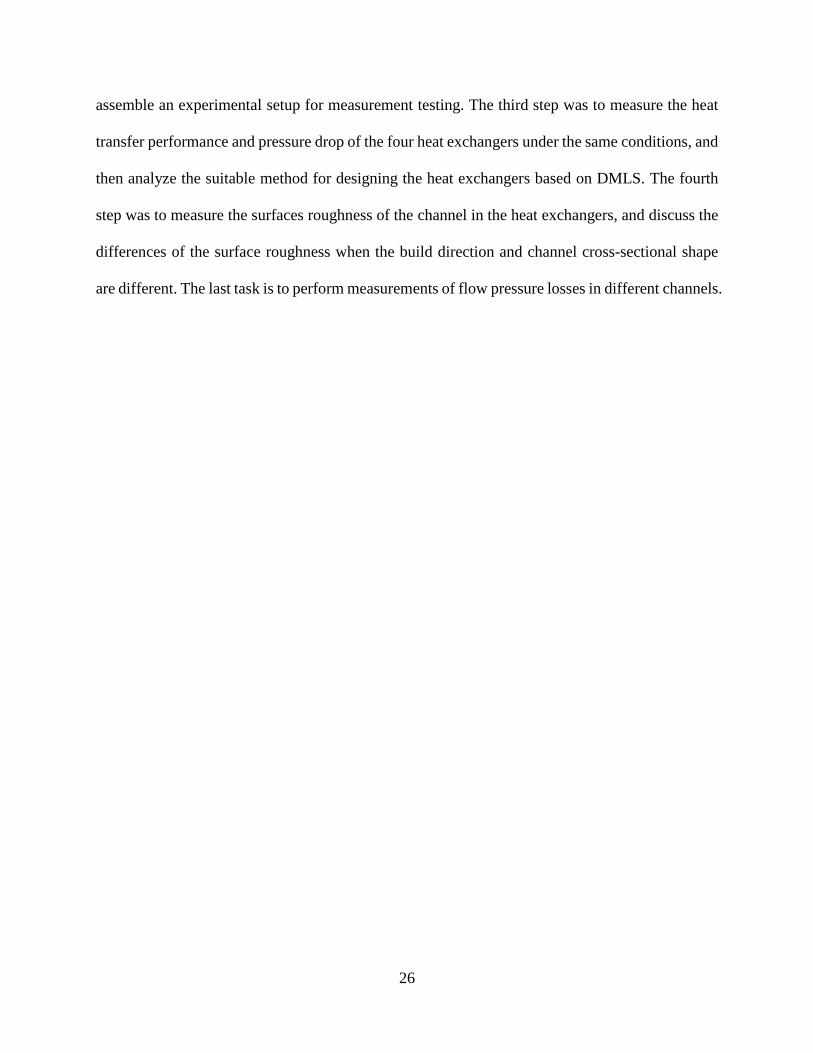
Figure 10 shows the average heat exchange rate and overall heat exchanger conductance,
defined as UA, of these four types heat exchangers, measured for various Reynolds number
conditions on the hot and cold sides. Both of these two parameters are related to the heat transfer
performance of the heat exchanger.
Figure 10 Average heat transfer rate and the overall heat exchanger conductance with the same Reynolds
number
As shown in Figure 10, the heat transfer performance of the four types of heat exchangers
increases with an increasing Reynolds number. In comparison with other three types of heat
exchangers, Type 2 has the largest average heat transfer rate and overall heat exchanger
conductance at the same Reynolds number. More importantly, it can be seen from the Figure 10b
that the total heat transfer coefficient values in order from small to large are Type 1, Type 2, Type
4, and Type 3. Therefore, the difference between the four heat exchangers’ heat transfer
performance in Figure 10 can be attributable to the difference in heat transfer area. This can
indicate that the heat transfer area plays a more important role in the heat transfer performance for
such compact heat exchangers using air as the fluid medium.
0
2
4
6
8
10
12
14
0 50 100 150 200 250
Q (
W)
Re
Type1Type2Type3Type4
0
0.2
0.4
0.6
0.8
1
1.2
1.4
0 50 100 150 200 250
UA
(W
/K)
Re
Type1Type2Type3Type4

37
Figure 11 shows the average pressure drop of the hot-side and cold-side air according to
the change of the air flow rate. The air flow rate at the hot-side inlets is always the same as that at
cold-side inlet. As the air flow rate increases, the pressure drop becomes greater due to the increase
in flow resistance. Compared with Type 1, Type 2 has a larger number of channels, which increases
the free flow area, and as a result, the pressure drop of Type 2 is smaller. The pressure drop and
its increasing trend of Type 3 and Type 4 are larger than those of Type 1 and Type 2 due to the
reduction in the number of channels and curved channels. With similar curved channel structure,
Type 4 has a smaller pressure drop than Type 3 because it increases the number of channels and
reduces the bending angle of the channel. Consequently, it can be seen that increasing the number
of channels to increase the free flow area can effectively reduce the pressure drop.
Figure 11 Average pressure drop with the same flow rate on hot and cold sides
Figure 12 shows the average Fanning friction factor of the hot-side and cold-side air
according to the change of the Reynolds number, which is calculated using Equation (24). The
Reynolds number of the hot-side and cold-side air is the same. The increase of the Reynolds
number represents the increase of the flow rate in the channel. As the Reynolds number increases,
0
100
200
300
400
500
600
700
0 10 20 30 40
Δp
(P
A)
Flow (L/min)
Type1
Type2
Type3
Type4

38
the graph shows the tendency of the average Fanning friction factor to decrease. It can be explained
from Equation (24) that the Fanning friction factor is inversely proportional to the square of the
average flow velocity of the fluid, so the friction factor will decrease as the fluid flow velocity
increases.
Figure 12 Average Fanning friction factor with the same Reynolds number on hot and cold sides
In addition to the fluid flow velocity, the friction factor is also related to the equivalent
shear force of the channel wall. As shown in Figure 12, Since the Type 1 and Type 2 heat
exchangers have straight channels inside, which reduces the flow resistance, their fanning friction
factors are lower than those of the Type 3 and Type 4 heat exchangers whose channels are S-
shaped structures. According to the simulation perform by Lee et al[24], the fanning friction factor
of circular channel is smaller than that of semicircular channel. However, the average fanning
friction factors obtained in this study for Type 1 and Type 2 heat exchangers are nearly the same.
One possible reason is that the inner wall surface of the heat exchanger channel manufactured by
the DMLS method cannot be perfectly smooth and has a certain degree of roughness. Our
experience in operating additive manufacturing machines, also confirmed by other researchers[31],
0
0.1
0.2
0.3
0.4
0.5
0.6
0.7
0.8
0 50 100 150 200 250
f
Re
Type1
Type2
Type3
Type4

39
suggests that surface roughness is related to the shape and size of the cross section of the channel
and the build direction. As a result, the surface roughness inside a channel will increase the
equivalent shear force, elevating the friction factors. The surface roughness inside the channel will
be measured and studied in the next chapter.
In order to comprehensively compare the performance of the four types of heat exchangers,
a relative performance coefficient 𝜂 is introduced, which is defined as:
𝜂 =𝜀/𝜀1
(Δ𝑝/Δ𝑝1)(4 − 1)
where 𝜀 is the heat exchanger effectiveness, Δ𝑝 is the pressure drop, the subscripts 1 represents
the Type 1 heat exchanger, because the Type 1 is used as a contrast.
Figure 13 Relative performance coefficient 𝜂 with the same flow rate
As shown in Figure 13, at the same flow rate, the Type 2 heat exchanger has the best
performance, and its coefficient of performance is about 13% higher than that of the Type 1 heat
exchangers. Type 3 and Type 4 are significantly lower, the magnitudes of their heat exchanger
effectiveness are lower than that of Type 1 and the pressure drops are relatively high, resulting in
0
0.2
0.4
0.6
0.8
1
1.2
1.4
0 5 10 15 20 25 30 35 40
𝜂
Flow (L/min)
Type1Type2Type3Type4

40
lower levels of performance overall. To a certain extent, the lower performances of Type 3 and
Type 4 are somewhat unexpected.
In this study, air is used as the fluid medium in the heat exchanger and the air flow rate
ranges from 6.5 to 37.7 L/min. The thermal conductivity of air is lower compared to the liquid
medium, and due to the low air velocity, the heat transfer coefficient of the heat exchanger is also
lower. Therefore, for such compact heat exchangers using air as the fluid medium and operating
at low air flow rate, the influence of increasing the heat exchange area of the heat exchanger by
directly increasing the number of channels is more important than the influence of improving the
heat transfer coefficient of each channel by bending the channels.
In conclusion, when the fluid medium in the heat exchanger is air and the air flow rate
range is 6.5 to 37.7 L/min, the increase in heat transfer area will play a more significant role in
improving the overall heat transfer performance of the heat exchanger. Consequently, the Type 2
design method, which is the method that maximizes the number of channels inside the heat
exchanger to increase the heat exchange area by the densest arrangement, is more suitable for
compact heat exchangers based on DMLS. To improve the performance of Type 3 and Type 4 heat
exchangers, one plausible approach is to reduce the volume occupied by each channel and by
reducing the angle of channel bending, thereby increasing the total number of channels in the heat
exchanger.

41
4.2 Surface Roughness and Geometric Feature of Channels
DMLS is one of the advanced technologies for metal additive manufacturing. This
technology makes it possible to manufacture metal parts with complex geometries and enables
rapid manufacturing prototypes. However, the main drawbacks that exist when using DMLS
method are that the surface roughness and dimensional deviation of the manufactured metal parts
are large, which is an inherent result of this method[42]. Figure 14 shows the cross-sectional view
of the heat exchangers manufactured through the DMLS method. The two metal parts shown in
the figure are a quarter portion of the straight channel heat exchangers investigated in this study,
which are made of stainless steel SS316. Since the flow arrangement of the heat exchangers is
cross-flow, this results in different build directions for the channels on different sides. Figure 15
shows the inner view of the channel, where the channel surface is not smooth but has a degree of
surface roughness.
Figure 14 Cross-sectional view of the heat exchangers investigated in this study

42
Figure 15 Inner view of the channel through microscope
There is a number of factors that affect the build quality of metal parts manufactured by
the DMLS method, such as laser scan speed, scan spacing, material powder, support structure, and
build direction[31]. For the heat transfer channels studied here, the build direction, as well as the
geometric shape and size of the channel, greatly contribute to the final surface roughness and
morphology. Figure 16 shows the morphology differences of four types of channels, the images
were obtained by utilizing scanning electron microscope (SEM). The four types of channels were
made from the same manufacturing process and materials, but with different geometric shapes and
build directions.

43
Figure 16 Morphology differences between channels with different build directions and geometric shapes
In Figure 16a, the cross-sectional shape of the channels is circular, and the channels are
built vertically, which means that the build direction is parallel to the axial or flow direction of the
channel, while in Figure 16b, the cross-sectional shape of the channels is also circular, but the
channels are built horizontally, the build direction is perpendicular to the axial direction of the
channel. For the channels shown in the Figure 16c and Figure 16d, their cross-sectional shapes are
both semicircular, and they are built in the vertical and horizontal directions, respectively. It can
be clearly seen that different build directions and geometric shape introduce different
characteristics of surface roughness and geometric feature changes. More importantly, since the
metal parts are constructed by sintering metal powder layer by layer along the build direction when

44
using the DMLS method, the surface roughness and shape of the channel edge on the side without
the support structure undergoes obvious changes under gravity.
Understandably, roughness and morphological changes in an additive-manufactured
channel will affect the pressure loss and heat transfer. Therefore, it is necessary to measure and
evaluate the surface roughness and geometric feature in the channels. The purpose of this chapter
is to evaluate the average surface roughness and geometric feature changes produced by the DMLS
method and their effects on the pressure loss through the heat exchanger channels.
4.2.1 Surface Roughness and Geometric Feature Evaluation
A custom-developed method based on SEM micrographs was adopted for evaluating the
surface roughness and geometric features of additive-manufactured channels[43]. Type 1 and Type
2 heat exchangers studied above were cut into four sections in order to capture the surface features
of the channels as shown in Figure 17. Therefore, there are a total of six surfaces for each heat
exchanger (three surfaces perpendicular to the construction direction and other three surfaces
parallel to the construction direction) can be investigated and analyzed by applying SEM images
and image segmentation techniques. For each surface, a number of 24 to 50 holes were imaged
and analyzed.

45
Figure 17 Illustrative graph for heat exchangers cutting
After obtaining the SEM micrographs of each surface, the area occupied by the holes and
the geometric profiles of the holes were extracted by judging the grayscales levels, and then the
centroid coordinates of each hole can be calculated based on the numerical integration. For a
circular hole, the centroid is its center point. For a semicircular hole, the line connecting the center
point of the concentric circle and the centroid of the semicircle is perpendicular to its diameter.
The distance ∆𝑦𝑐𝑒𝑛𝑡𝑟𝑜𝑖𝑑 between the center point and centroid of a semicircular hole can be
obtained by Equation (4-2):
∆𝑦𝑐𝑒𝑛𝑡𝑟𝑜𝑖𝑑 =4𝑅𝑠𝑒𝑚𝑖𝑐𝑖𝑟𝑐𝑙𝑒
3𝜋(4 − 2)
where 𝑅𝑠𝑒𝑚𝑖𝑐𝑖𝑟𝑐𝑙𝑒 is the designed radius of semicircular channels. The subsequent step is to draw
the designed geometric profile of the hole through the positioned center point and the designed
radius in a polar coordinate, in which the origin is set at the concentric circle center point of each
hole. Figure 18 demonstrates the examples of the designed profiles for different channels. The red
crosses in the figure indicate the concentric circle center points of the channel cross-sections.

46
Figure 18 Designed profiles for different channels
The mean radius, Rm, and the arithmetical deviation of the assessed profile for each cut of
cross-section, Ra, were evaluated to represent the change in the geometric features of the channels
and the average surface roughness, as suggested by Equations (4-3,4). For each type of channel,
there were 72 to 150 cross-sectional cuts used to determine the average surface roughness and the
actual size of the channels.
𝑅𝑚 =∫ 𝑅(𝜃)𝑑𝜃
2𝜋=
1
𝑛∑ 𝑅𝑖
𝑛
(4 − 3)
𝑅𝑎 =1
𝑛∑|∆𝑦𝑖|
𝑛
(4 − 4)

47
where 𝑅𝑖 is the actual radius of the point selected on the geometric profile, ∆𝑦𝑖 is the deviation of
the point on the actual profile from the corresponding point on the designed profile.
Figure 19-20 shows the examples of actual profiles for circular and semicircular channels
with different build directions. The data line in each figure is the actual profile of the channel cross
section, while the nearly centered, horizontal line is the actual average radius. Note that when
evaluating a semicircular channel, the cross-sectional profile of the channel is divided into two
parts, one is an arc edge part and the other is a straight edge part. The main reason is that the
geometric characteristics of the straight edge are different from the arc edge, which leads to
different surface roughness. Therefore, the straight part needs to be analyzed separately.
Figure 19 Examples of actual profiles for circular channel

48
Figure 20 Examples of actual profiles for semicircular channel
Figure 21 demonstrates the comparison of hydraulic radius for different channels, the
designed hydraulic radius of each channel is 500 μm. However, it can be seen that the actual
hydraulic radius of the four channels is smaller than the designed hydraulic radius. Compared with
semicircular channels, the hydraulic radius of circular channels is smaller on average. Among them,
the hydraulic radius of the horizontally built circular channels is the smallest, which is about 17.8%
smaller than the designed value. The main reason is that although the circular channels and the
semicircular channels have the same design hydraulic radius, the radius of the concentric circle of
the semicircular channels is 1.6 times that of the circular channels, which means that the geometric
features of the circular channels are smaller. Consequently, when the laser processing diameter is
1mm, channels with smaller geometric features will have greater geometric profile deviations,

49
which is specifically reflected in the shape, size and surface roughness of the channels. For the
channels with the same cross-sectional shape, it is clear that the change in the geometrical features
of channels with horizontal build direction is greater than that of channels with vertical build
direction. This is because during the DMLS process, the channels are constructed by stacking and
sintering metal powder layer by layer. For horizontally printed channels, the metal powder will
not immediately condense after being melted by the laser during processing. Due to the lack of a
support structure, part of the channel edge will be suspended, causing deformation under the action
of gravity. In contrast, for vertically printed channels, this factor has less impact because there are
no suspended structures in the design.
Figure 22 demonstrates the comparison of surface roughness for different channels. For
channels with the same cross-sectional shape, the build direction has a significant influence on the
level of surface roughness. Regardless of the circular channels or the semicircular channels, the
surface roughness of the channels introduced through the horizontal build direction is much greater
than that introduced through the vertical build direction. The reason is the same as described above.
For vertically built channels, the average surface roughness of the circular channels, the arc part
and straight part of the semicircular channels is close to each other. The value of the circular
channels surface roughness is only about 2% higher than that of other two cases. However, when
the build direction is horizontal, the differences among them become more significant. It can be
seen that in the horizontal build direction, compared with the circular channels, the straight part of
the semicircular channels has the smallest surface roughness, which is about 54.2% lower than that
of the circular channels. On the other hand, since the geometric size of the arc part of the
semicircular channels is larger than that of the circular channels, this makes the surface roughness
of the arc part the semicircular channels slightly smaller than that of the circular channels by about
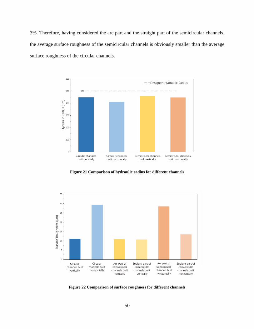
50
3%. Therefore, having considered the arc part and the straight part of the semicircular channels,
the average surface roughness of the semicircular channels is obviously smaller than the average
surface roughness of the circular channels.
Figure 21 Comparison of hydraulic radius for different channels
Figure 22 Comparison of surface roughness for different channels

51
In summary, the build direction has a great influence on the surface roughness and
geometric features of the channels. For channels manufactured by the DMLS method, when the
designed hydraulic diameter of the channel is 1mm, the surface roughness and geometric feature
changes of the semicircular channels are smaller than those of the circular channels. For these
circular channels, when the construction direction is changed from vertical to horizontal, the size
of the channel will decrease by about 8.4%, the surface roughness will increase by about 165%,
and the geometric profile of the cross section will become noticeably irregular. For the semicircular
channels with a designed hydraulic diameter of 1mm, when the construction direction is changed
from vertical to horizontal, the channel size will decrease by about 2.6%, the surface roughness
will increase by approximately 163% in the arc part, and approximately 23.9% in the straight part
and the geometry profile of the cross section will also become irregular. Therefore, for the final
quality of the manufactured channels, the vertically built semicircular channels have better quality,
while the quality of the horizontally built circular channels is worse.
4.2.2 Pressure Drop Characteristics
Before the heat exchangers were cut into four parts, the previous experimental setup was
used to measure the pressure drop of these four types of channels. The air inlet temperature is
about 25 degrees Celsius and the flow rate ranges from 6.5 to 37.7 L/min. In order to simplify the
expression, C1, C2, S1, and S2 will be used in the following figures to represent vertically built
circular channels, horizontally built circular channels, vertically built semicircular channels, and
horizontally built semicircular channels, respectively. The designed hydraulic diameter of the four

52
types of channels is 1mm, but due to the processing characteristics of DMLS, the actual hydraulic
diameter changes from the designed value.
Figure 23 Comparison of pressure drops with the same Reynolds number
Figure 23 demonstrates the pressure drop according the change of Reynolds number. When
the Reynolds number is less than 120, the increase in pressure drop for all the four channels is
insensitive to Reynolds number. However, when the Reynolds number is greater than 120, the
increasing trend of the pressure drop vs. Reynolds number for the channels with the horizontal
build direction becomes steeper, due to the changes in surface roughness and geometric features.
By applying SEM images and image segmentation techniques, the horizontally built circular
channels have the largest average surface roughness and the largest change in geometric features,
which results in the highest pressure loss among these channels. In order to further analyze the
flow resistance in the channel, consider using the fanning friction factor as a comparison parameter
in this study.
0
40
80
120
160
200
240
280
0 50 100 150 200 250
Δp
(P
A)
Re
C1 C2
S1 S2

53
Figure 24 Comparison of the Fanning friction factors with the same Reynolds number
Figure 24 demonstrates the comparison of the fanning friction factors for these four type
channels. An increase in the fanning friction factor indicates an increase in the flow resistance of
the fluid in the channel. Note that this time the friction factor is calculated by Equation (24) using
the actual mean hydraulic diameter of the channel. The fanning friction factor of C1 is slightly
lower than that of S1, which indicates that the flow resistance in the circular channel is lower
compare to the semicircular channel, even though the surface roughness and geometric feature
changes of C1 are slightly higher than those of S1. This means that when the surface roughness
and geometric feature changes of the channels manufactured by the DMLS method are similar, the
fluid in the circular channel has less pressure loss than that in the semicircular channel.
On the other hand, due to the increase in the surface roughness and geometric feature
changes of channels, the fanning friction factor of C2 is 49.6% larger than that of C1, while the
fanning friction factor of S2 is 40.9% higher than that of S1. Since the increase of the surface
roughness in the straight part of the semicircular channel is not as significant as that in the arc part,
which limits the further increase in the flow resistance in the semicircular channel.
0
0.1
0.2
0.3
0.4
0.5
0.6
0.7
0.8
0 50 100 150 200 250
f
Re
C1 C2
S1 S2

54
In summary, pressure drop testing exhibited that the vertically built channel had a smaller
fanning friction factor than the horizontally built channel, which was attributed to differences in
surface roughness and geometric feature changes. Therefore, a conclusion can be drawn that the
build direction of the channel plays a considerable role in the pressure loss. In addition, for
channels manufactured by the DMLS method with the same hydraulic diameter, the vertically built
circular channel has the smallest fanning friction factor compared to the other three types of
channels. However, when the build direction is horizontal, the increase in fanning friction factor
of the circular channel is the greatest, caused by its significant surface roughness and geometric
profile distortion.

55
5.0 Conclusion
In this study, four compact heat exchangers with different channel characteristics were
manufactured by the DMLS method of Stainless Steel SS316. This is followed by an experimental
study to examine the heat transfer performance and pressure drop of these four types of heat
exchangers. The experiment used air as flow medium of laminar regime and the inlet and outlet
flow temperatures were kept at 52 and 25 degrees Celsius, respectively. Results from the present
study suggest that the heat exchanger of the straight channel with circular cross-sectional shape
performs the best, as it inherits high heat transfer performance and low pressure drop, both are
attributable to its high total heat transfer surface area and the less restrictive flow cross-section in
a fixed volume.
In addition to the thermos-fluid studies on the additive-manufactured compact heat
exchangers, SEM images and image segmentation techniques were applied to evaluate the surface
roughness and geometric characteristics of circular and semicircular channels with different
DMLS build directions. The results show that the vertical build direction leads to better product
quality in roughness and geometric features, compared to the horizontal build direction. In addition,
the surface roughness and geometric feature changes of the circular channels were generally
greater than those of the semicircular channels, due to the smaller geometric features for the
circular cross section.
The final task is to study the pressure drop as a result of rough channel caused by different
DMLS build directions. If the channel was built in the vertical direction along the channel axis,
the flow resistance in the circular channel was slightly smaller than that of the semicircular channel.
However, when the build direction was horizontal, this trend is reversed, as the circular cross-

56
sectional channel presents higher flow resistance, due mainly to the greater changes in the surface
roughness and geometric features of the circular channels.
Based on the collective findings of the current study, suggested below are potential follow-
up research topics:
(1) Reduce the bending angle of the curved channel to decrease the volume occupied by
each channel, so more channels can be placed in the heat exchanger with a fixed
volume, enhancing the overall heat transfer surface area while reducing the pressure
drop.
(2) The cross-sectional shape of the channel can be further optimized with other options,
such as a rectangle with rounded corners. The rectangular channel has the potential of
elevating heat exchange performance, while the drawback is that its internal friction
factor might be high. Adding rounded corners in a rectangular channel eliminates the
sharp-edge effect and reduces the flow resistance.
(3) Explore ways to reduce the surface roughness and geometrical feature changes of heat
exchanger channels manufactured by DMLS. This can be accomplished by optimizing
the process control and operating parameters, such as laser power, scanning speed,
scanning surface spacing and powder selection.

57
Bibliography
[1] D. A. Reay, “Compact heat exchangers, enhancement and heat pumps,” Int. J. Refrig., vol.
25, no. 4, pp. 460–470, 2002.
[2] S. S. Mehendafe, A. M. Jacobi, and R. K. Shah, “Fluid flow and heat transfer at micro-
and meso-scales with application to heat exchanger design,” Appl. Mech. Rev., vol. 53, no.
7, pp. 175–193, 2000.
[3] D. P. Sekulic, Compact heat exchangers. 2018.
[4] W. xiao Chu, X. hui Li, T. Ma, Y. tung Chen, and Q. wang Wang, “Experimental
investigation on SCO2-water heat transfer characteristics in a printed circuit heat
exchanger with straight channels,” Int. J. Heat Mass Transf., vol. 113, pp. 184–194, 2017.
[5] A. M. Aneesh, A. Sharma, A. Srivastava, and P. Chaudhury, “Effects of wavy channel
configurations on thermal-hydraulic characteristics of Printed Circuit Heat Exchanger
(PCHE),” Int. J. Heat Mass Transf., vol. 118, pp. 304–315, 2018.
[6] N. Tsuzuki, Y. Kato, and T. Ishiduka, “High performance printed circuit heat exchanger,”
Appl. Therm. Eng., vol. 27, no. 10, pp. 1702–1707, 2007.
[7] D. Kwon, L. Jin, W. S. Jung, and S. Jeong, “Experimental investigation of heat transfer
coefficient of mini-channel PCHE (printed circuit heat exchanger),” Cryogenics (Guildf).,
vol. 92, no. March, pp. 41–49, 2018.
[8] J. H. Jeong, L. S. Kim, J. K. Lee, and M. Y. Ha, “REVIEW OF HEAT EXCHANGER
STUDIES FOR HIGH-EFFICIENCY GAS TURBINES,” pp. 1–8, 2016.
[9] K. Thulukkanam, Heat Exchanger Design Handbook. 2013.
[10] C. Desai, H. R. Mehta, and P. Pillay, “Fabrication and Assembly Method for Synchronous
Reluctance Machines ,” IEEE Transactions on Industry Applications , vol. 54, no. 5.
IEEE , pp. 4227–4235, 2018.
[11] S. Mylavarapu, X. Sun, J. Figley, N. Needler, and R. Christensen, “Investigation of high-
temperature printed circuit heat exchangers for very high temperature reactors,” J. Eng.
Gas Turbines Power, vol. 131, no. 6, 2009.
[12] D. M. Allen, “Photochemical Machining : from ‘ manufacturing ’ s best kept secret ’ to a
$ 6 billion per annum , rapid manufacturing process,” no. 2, 1826.
[13] O. Çakir, A. Yardimeden, and T. Özben, “Chemical machining,” vol. 28, no. 8, pp. 499–
502, 2007.

58
[14] S. K. Mylavarapu, X. Sun, R. N. Christensen, and J. Vaughn, “On the diffusion bonding
of Alloy 617 for high-temperature compact heat exchangers,” Transactions, vol. 101, no.
1, pp. 370–372, 2009.
[15] S. K. Mylavarapu, X. Sun, R. N. Christensen, R. R. Unocic, R. E. Glosup, and M. W.
Patterson, “Fabrication and design aspects of high-temperature compact diffusion bonded
heat exchangers,” Nucl. Eng. Des., vol. 249, pp. 49–56, 2012.
[16] A. Simchi, F. Petzoldt, and H. Pohl, “On the development of direct metal laser sintering
for rapid tooling,” vol. 141, pp. 319–328, 2003.
[17] J. Kruth, M. Badrossamay, E. Yasa, J. Deckers, L. Thijs, and J. Van Humbeeck, “Part and
material properties in selective laser melting of metals.”
[18] E. Chlebus, K. Gruber, B. Ku, J. Kurzac, and T. Kurzynowski, “Materials Science &
Engineering A Effect of heat treatment on the microstructure and mechanical prop- erties
of Inconel 718 processed by selective laser melting,” vol. 639, pp. 647–655, 2015.
[19] Y. Yang, D. Wang, X. Su, and Y. Chen, “Design and rapid fabrication of non-assembly
mechanisms,” 2010 Int. Conf. Manuf. Autom., vol. 1, pp. 61–63, 2010.
[20] B. A. Raj, J. T. W. Jappes, M. A. Khan, and V. D. N. C. Brintha, “Studies on heat
treatment and electrochemical behaviour of 3D printed DMLS processed nickel ‑ based
superalloy,” Appl. Phys. A, pp. 1–8, 2019.
[21] M. C. Leu and A. Arbor, “Additive Manufacturing : Current State , Future Potential , Gaps
and Needs , and Recommendations,” vol. 137, no. February, pp. 1–10, 2015.
[22] S. Yoon, P. Sabharwall, and E. Kim, “Numerical study on crossflow printed circuit heat
exchanger for advanced small modular reactors,” Int. J. Heat Mass Transf., vol. 70, pp.
250–263, 2014.
[23] J. Wang, Y. Sun, M. Lu, J. Wang, and X. Yan, “Study on the Thermal-hydraulic
Performance of Sinusoidal Channeled Printed Circuit Heat Exchanger,” Energy Procedia,
vol. 158, pp. 5679–5684, 2019.
[24] S. M. Lee and K. Y. Kim, “Comparative study on performance of a zigzag printed circuit
heat exchanger with various channel shapes and configurations,” Heat Mass Transf. und
Stoffuebertragung, vol. 49, no. 7, pp. 1021–1028, 2013.
[25] N. S. Berbish, M. Moawed, M. Ammar, and R. I. Afifi, “Heat transfer and friction factor
of turbulent flow through a horizontal semi-circular duct,” pp. 377–384, 2011.
[26] H. C. Reynolds, T. B. Swearingen, and D. M. McEligot, “Thermal entry for low Reynolds
number turbulent flow,” 1969.
[27] J.-J. Hwang, “Heat transfer-friction characteristic comparison in rectangular ducts with slit
and solid ribs mounted on one wall,” 1998.

59
[28] D. E. Kim, M. H. Kim, J. E. Cha, and S. O. Kim, “Numerical investigation on thermal-
hydraulic performance of new printed circuit heat exchanger model,” Nucl. Eng. Des., vol.
238, no. 12, pp. 3269–3276, 2008.
[29] Y.-D. C. and K.-J. L. Jang-Won Seo, Yoon-Ho Kim,Dongseon Kim, “Heat Transfer and
Pressure Drop Characteristics in Straight Microchannel of Printed Circuit Heat
Exchangers,” Entropy, pp. 3438–3457, 2015.
[30] I. H. Kim, H. C. No, J. I. Lee, and B. G. Jeon, “Thermal hydraulic performance analysis of
the printed circuit heat exchanger using a helium test facility and CFD simulations,” vol.
239, pp. 2399–2408, 2009.
[31] J. C. Snyder, C. K. Stimpson, K. A. Thole, and D. Mongillo, “Build Direction Effects on
Additively Manufactured Channels,” vol. 138, no. May 2016, pp. 1–8, 2019.
[32] K. L. Kirsch and K. A. Thole, “Heat Transfer and Pressure Loss Measurements in
Additively Manufactured Wavy Microchannels,” 2019.
[33] C. K. Stimpson, J. C. Snyder, K. A. Thole, and D. Mongillo, “Roughness Effects on Flow
and Heat Transfer for Additively Manufactured Channels,” vol. 138, no. May 2016, pp. 1–
10, 2019.
[34] X. Zhang, R. Tiwari, A. H. Shooshtari, and M. M. Ohadi, “An additively manufactured
metallic manifold-microchannel heat exchanger for high temperature applications,” Appl.
Therm. Eng., vol. 143, no. July, pp. 899–908, 2018.
[35] A. Bejan, Convection Heat Transfer. Somerset, UNITED STATES: John Wiley & Sons,
Incorporated, 2013.
[36] P. W. Deshmukh, S. V Prabhu, and R. P. Vedula, “Heat Transfer Enhancement for
Laminar Flow in Tubes Using Curved Delta Wing Vortex Generator Inserts,” Appl.
Therm. Eng., 2016.
[37] S. Eiamsa-ard and P. Promvonge, “Numerical study on heat transfer of turbulent channel
flow over periodic grooves,” Int. Commun. Heat Mass Transf., vol. 35, no. 7, pp. 844–
852, 2008.
[38] W. Q. Tao, Y. L. He, Q. W. Wang, Z. G. Qu, and F. Q. Song, “A unified analysis on
enhancing single phase convective heat transfer with field synergy principle,” Int. J. Heat
Mass Transf., vol. 45, no. 24, pp. 4871–4879, 2002.
[39] R. K. Shah and D. P. Sekulic, “Fundamentals of heat exchanger design.” John Wiley &
Sons, Hoboken, NJ, 2003.
[40] “Division 1 Rules for Construction of Pressure Vessels,” 2010 ASME Boil. Press. Vessel
Code, 2010.
[41] “Part D Properties (Metric),” 2010 ASME Boil. Press. Vessel CODE, 2010.

60
[42] E. O. Olakanmi, R. F. Cochrane, and K. W. Dalgarno, “Progress in Materials Science A
review on selective laser sintering / melting ( SLS / SLM ) of aluminium alloy powders :
Processing , microstructure , and properties,” J. Prog. Mater. Sci., vol. 74, pp. 401–477,
2015.
[43] Min, Z., Wu, Y. J., Yang, K. L., Xu, J., Parbat, S. N., Chyu, M. K., 2020. Dimensional
Characterizations Using SEM And Surface Improvement With Electrochemical Polishing
Of Additively Manufactured Microchannels. ASME Turbo Expo 2020: Turbomachinery
Technical Conference and Exposition, June 22-26, 2020, London, England, Paper Number
GT2020-14842 (Accepted)