title of sop - homepage | california air resources … station operator aqis may occasionally...
TRANSCRIPT
TECHNICAL SERVICES DIVISION
QUALITY ASSURANCE PROJECT PLAN
STANDARD OPERATING PROCEDURE
AIRMON SOP 215
THERMO 49
REVISION 215.2.00 08/29/2012
Glen Colwell, Manager Date Mark Stoelting, QA Officer Date Air Monitoring Section Technical Services Division
Technical Services Division 939 Ellis Street San Francisco CA 94109
AirMon SOP 215 Thermo 49.docx Page 2 of 31 Revision 215.2.00
TABLE OF CONTENTS
Section Page
LIST OF FIGURES .........................................................................................................................4
1. PURPOSE ..............................................................................................................................5
2. SUMMARY OF METHOD ...................................................................................................5
3. DEFINITIONS .......................................................................................................................8
4. HEALTH AND SAFETY WARNINGS ................................................................................9
5. CAUTIONS ............................................................................................................................9
6. INTERFERENCES AND LIMITATIONS ............................................................................9
7. PERSONNEL QUALIFICATIONS AND RESPONSIBILITIES .........................................9
8. EQUIPMENT AND SUPPLIES ..........................................................................................10
9. PROCEDURES ....................................................................................................................10 9.1 Initial Setup .................................................................................................................10 9.2 Acceptance Testing .....................................................................................................12
9.3 Calibration ..................................................................................................................13 9.3.1 Procedure: Full calibration (including adjustment) ........................................13
9.3.2 Procedure: Manual Span and Zero Verification .............................................14 9.3.3 Procedure: Manual Precision ..........................................................................14
9.4 Auto-Calibration, ‘Auto-Cals’ ....................................................................................15 9.5 Service and Maintenance ............................................................................................16
9.5.1 Procedure: Change Inlet Filter .......................................................................18 9.5.2 Procedure: Cooling Fan Filter Servicing ........................................................18
9.5.3 Procedure: Instrument Internal Cleaning .......................................................19 9.5.4 Procedure: Capillary Inspection and Cleaning ...............................................19 9.5.5 Procedure: External Pump Rebuild ................................................................19 9.5.6 Procedure: Internal Pump Rebuild .................................................................20 9.5.7 Procedure: Cell Cleaning ................................................................................20
9.5.8 Procedure: Scrubber replacement ...................................................................21 9.6 Sample Collection .......................................................................................................22
9.7 Sample Handling and Preservation .............................................................................22 9.8 Sample Preparation and Analysis ...............................................................................22 9.9 Troubleshooting ..........................................................................................................22 9.10 Computer Hardware and Software .............................................................................24
10. DATA AND RECORDS MANAGEMENT ........................................................................25

AirMon SOP 215 Thermo 49.docx Page 3 of 31 Revision 215.2.00
11. QUALITY CONTROL AND QUALITY ASSURANCE ...................................................25
11.1 Quality Control ...........................................................................................................25 11.2 Quality Assurance .......................................................................................................27
12. AUTHORS ...........................................................................................................................28
13. REFERENCES .....................................................................................................................28
14. APPENDIXES .....................................................................................................................29 14.1 Appendix A: 49 Specifications ...................................................................................29 14.2 Appendix B: 49C Alarm Flags ...................................................................................30 14.3 Appendix C: 49i Alarm Flags .....................................................................................31

AirMon SOP 215 Thermo 49.docx Page 4 of 31 Revision 215.2.00
LIST OF FIGURES
Figure 1: THERMO 49C Flow Schematic ..................................................................................... 6
Figure 2: THERMO 49C Front Panel ............................................................................................. 6
Figure 3: THERMO 49i Flow Schematic ....................................................................................... 7
Figure 4: THERMO 49i Front Panel .............................................................................................. 7
Figure 5: THERMO 49C Rear Panel ............................................................................................ 12
Figure 6: THERMO 49i Rear Panel.............................................................................................. 12
Figure 7: Suggested Maintenance Schedule ................................................................................. 16
Figure 8: Internal Components 49C .............................................................................................. 17
Figure 9: Internal Components 49i ............................................................................................... 18
Figure 10: Optical bench assembly ............................................................................................... 21
Figure 11: BAAQMD Station/Shelter Temperature Criteria ........................................................ 26
Figure 12: BAAQMD QC Limits for O3 ...................................................................................... 26
Figure 13: BAAQMD MQO’s for O3 .......................................................................................... 27
Figure 14: BAAQMD Internal Audit Acceptance Criteria ........................................................... 27
AirMon SOP 215 Thermo 49.docx Page 5 of 31 Revision 215.2.00
1. PURPOSE
This Standard Operating Procedure (SOP) describes the installation, setup, general operation,
calibration, maintenance, data collection, troubleshooting and repair of the Thermo Fischer
Scientific, Inc. (THERMO) Model 49C or 49i O3 analyzer. NOTE: This SOP supplements the
procedures located in the THERMO Instrument Manual.
2. SUMMARY OF METHOD
The THERMO 49C or 49i are based on the principle of UV absorption whereby ozone (O3)
molecules absorb UV light at a wavelength of 254 nm. The degree to which the UV light is
absorbed is directly related to the ozone concentration as described by the Beer-Lambert Law:
I / I o = e-KLC
K = molecular absorption coefficient, 308 cm-1 (at 0C and 1 atmosphere)
L = length of cell, 38 cm
C = ozone concentration in parts per million (ppm)
I = UV light intensity of sample with ozone (sample gas)
Io = UV light intensity of sample without ozone (reference gas)
NOTE: Please refer to the appropriate THERMO Instrument manual for a further explanation.
The THERMO Model 49 is designated as an Equivalent Method by the United States
Environmental Protection Agency (EPA) for the measurement of ambient concentrations of O3
pursuant with the requirements defined in the Code of Federal Regulations (CFR), Title 40, Part
53.

AirMon SOP 215 Thermo 49.docx Page 6 of 31 Revision 215.2.00
Figure 1: THERMO 49C Flow Schematic
Figure 2: THERMO 49C Front Panel
©Thermo Fisher Scientific, Inc.
AirMon SOP 215 Thermo 49.docx Page 7 of 31 Revision 215.2.00
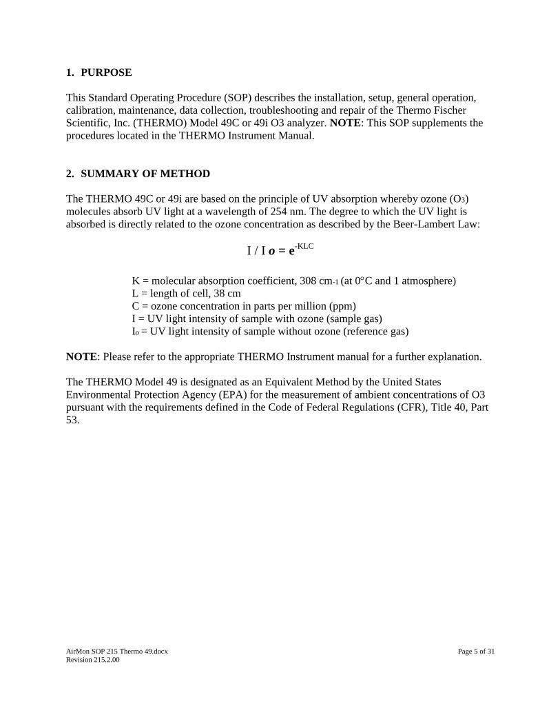
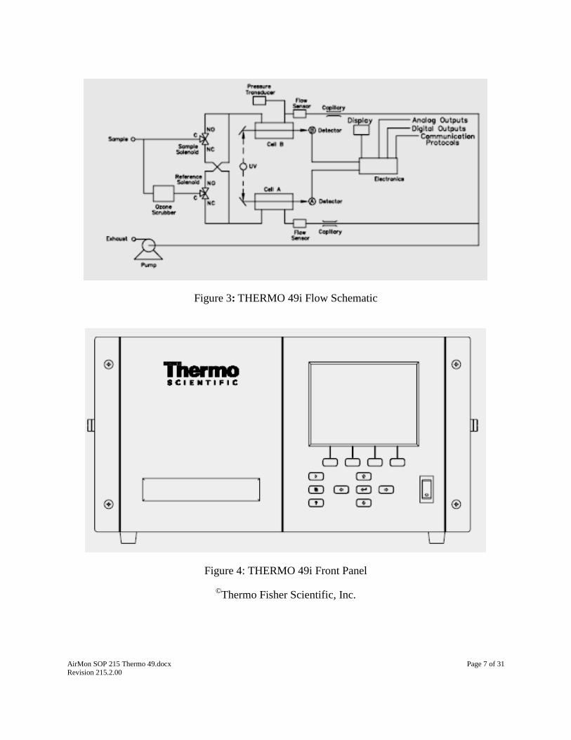
Figure 3: THERMO 49i Flow Schematic
Figure 4: THERMO 49i Front Panel
©Thermo Fisher Scientific, Inc.
AirMon SOP 215 Thermo 49.docx Page 8 of 31 Revision 215.2.00
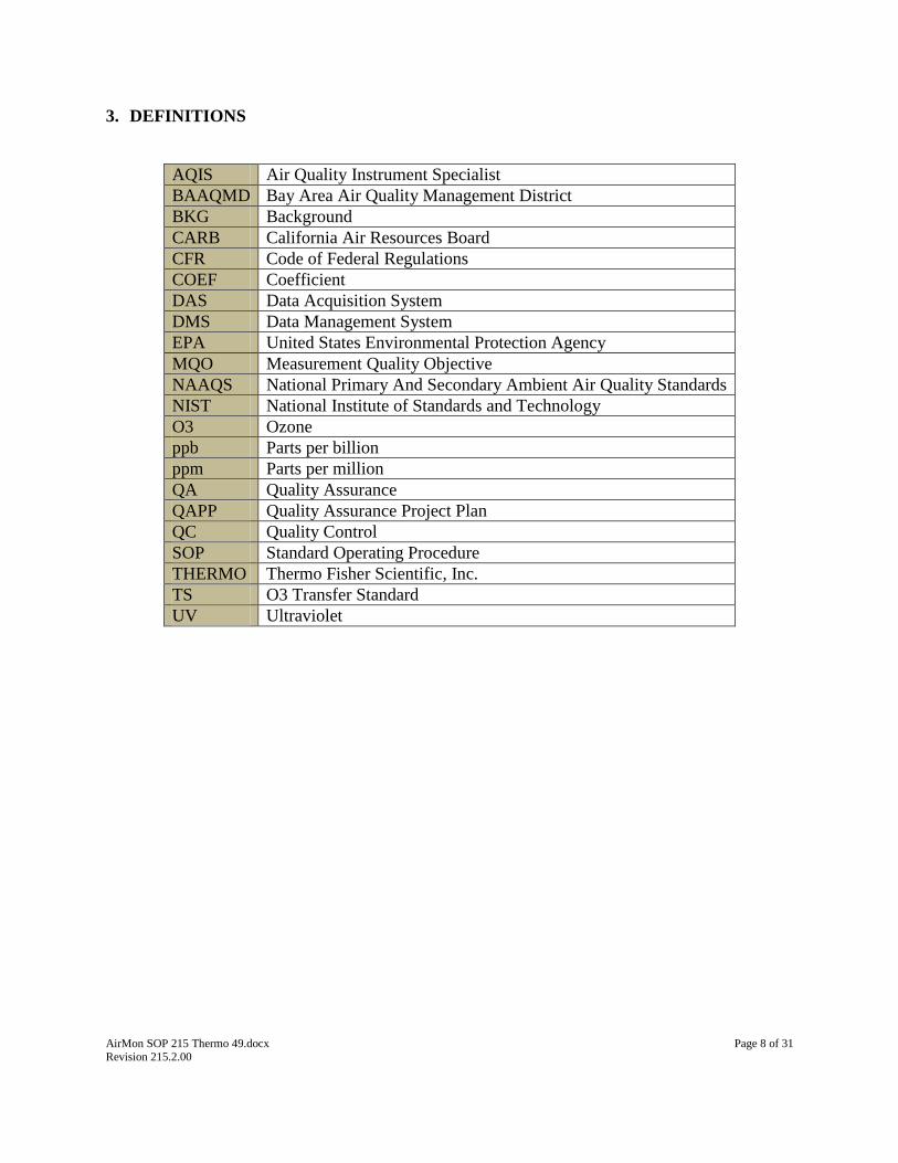
3. DEFINITIONS
AQIS Air Quality Instrument Specialist
BAAQMD Bay Area Air Quality Management District
BKG Background
CARB California Air Resources Board
CFR Code of Federal Regulations
COEF Coefficient
DAS Data Acquisition System
DMS Data Management System
EPA United States Environmental Protection Agency
MQO Measurement Quality Objective
NAAQS National Primary And Secondary Ambient Air Quality Standards
NIST National Institute of Standards and Technology
O3 Ozone
ppb Parts per billion
ppm Parts per million
QA Quality Assurance
QAPP Quality Assurance Project Plan
QC Quality Control
SOP Standard Operating Procedure
THERMO Thermo Fisher Scientific, Inc.
TS O3 Transfer Standard
UV Ultraviolet
AirMon SOP 215 Thermo 49.docx Page 9 of 31 Revision 215.2.00
4. HEALTH AND SAFETY WARNINGS
NOTE: Consult the THERMO Instrument Manual ‘Safety Precautions’ Sections for Preventive
Maintenance, Troubleshooting, and Servicing in Chapters 5, 6, and 7, respectively.
5. CAUTIONS
NOTE: Consult the THERMO Instrument Manual ‘Safety Precautions’ Sections for Preventive
Maintenance, Troubleshooting, and Servicing in Chapters 5, 6, and 7, respectively.
6. INTERFERENCES AND LIMITATIONS
Reactive materials, solvents and excessive particulates in the probe and sample inlet tubing could
be possible interferences. Monitoring should be temporarily stopped if local sources of potential
interferences are detected (i.e. paving, painting, etc.). Probe inlet tubing and manifold should be
cleaned if contamination is suspected. Any probe inlet tubing or manifold that has been replaced
or cleaned with water should be re-conditioned for at least 1 hour by running a manual O3 span.
Mercury vapor is a potential contaminant and should be avoided.
Lower detectable limit: 1 ppb (60 second averaging time)
7. PERSONNEL QUALIFICATIONS AND RESPONSIBILITIES
Installation, operation, maintenance, repair or calibration of the instrument and all support
equipment should only be performed by properly trained personnel. Personnel should meet all
minimum BAAQMD requirements and qualifications for an Air Quality Instrument Specialist
(AQIS) I or II, Senior AQIS, and/or Supervising AQIS.
The station operator AQIS is responsible for the operation and oversight of the
instrument and all support equipment. The operator shall complete any required or
recommended maintenance, minor repairs and/or occasional calibration of the instrument
and all support equipment. The station operator AQIS is responsible for all DMS data
review and validation. The station operator AQIS may occasionally install or replace an
instrument or support equipment. The Senior AQIS and Supervisor AQIS complete major
installations, repairs and calibrations.
BAAQMD MQA personnel manage the DMS and complete all final data review and
submittal.
BAAQMD PEG staff may conduct periodic performance and/or system’s audits.
CARB staff may conduct periodic performance and/or system’s audits.

AirMon SOP 215 Thermo 49.docx Page 10 of 31 Revision 215.2.00
EPA staff may conduct periodic performance and/or system’s audits.
8. EQUIPMENT AND SUPPLIES
The THERMO 49C or 49i are both normally installed and operated with the following
equipment:
THERMO Instrument Manual
Instrument bench or instrument rack. NOTE: Rack installation requires the use of the
appropriate instrument sliders securely attached to the analyzer!
Grounded 3-wire plug
10-micron Teflon filters and a Teflon filter holder assembly with appropriate fittings
¼” OD Teflon sample line tubing. The length of the tubing should be less than 10 feet
glass manifold
Inlet probe and probe line material installed following EPA siting requirements
external pump – Thomas vacuum pump
Calibrator
NOTE: At partial stations, the Model 49 must be set up with an internal ozone generator,
an external pump activated during calibrations, and an ozone scrubber assembly
Zero-air supply
Certified multi-blend cylinder with CO component and regulator
1/8” SS tubing (from cylinder to the calibrator) and appropriate fittings; NOTE: All gas
delivery connections should be leak tested upon installation!
Data Acquisition System (DAS) with appropriate cables and adaptors (RS-232, DB9,
CAT-5, etc.) with connection to the District’s Data Management System (DMS); NOTE:
Please refer to Section 10 of this SOP, “DATA AND RECORDS MANAGEMENT”
9. PROCEDURES
9.1 INITIAL SETUP
NOTE: Please refer to the appropriate THERMO Instrument Manual for further information.
1. Inspect a new analyzer for any external damage. Carefully remove the instrument cover and
check for any internal damage or missing parts. Check that all connectors and printed circuit
boards are firmly attached. Remove any shipping screws and packing materials
NOTE: For most applications, instruments must be installed and operated following EPA
requirements for siting and location.
2. Connect a sample line and external filter assembly to the SAMPLE IN bulkhead on the rear
panel of the analyzer. (Figure 5: THERMO 49C Rear Panel; Figure 6: THERMO 49i Rear
Panel)
AirMon SOP 215 Thermo 49.docx Page 11 of 31 Revision 215.2.00
3. OPTIONAL: Disconnect internal pump; connect the EXHAUST bulkhead to an external
pump. The line should be ¼ " OD. The length of the exhaust line should be as short as
possible. Verify that there is no restriction in this line.
4. Plug the analyzer into an outlet of the appropriate voltage and frequency.
5. Press the power switch to “ON.”
6. OPTIONAL: For ozone generator use (for nightly auto-calibrations):
a. Calibration line: Install ¼” line from the ozone out port on the back of the analyzer to
the probe inlet; at inlet install with a Tee fitting
b. Install an internal zero/span solenoid (NC) in-line with the ozone generator output;
c. Install zero-air scrubber assembly in-line with pump;
d. Install an external pump; connect to the appropriate bulkhead on back of analyzer and
set up for pump control; start pump, adjust back-pressure regulator to the appropriate
setting;
7. Adjust all appropriate analyzer settings for range, averaging time, alarms, internal data
logging and communications:
a. Range 0.5 ppm
b. Average Time 60 seconds
c. Span Coefficient = 1.000
d. Pressure Compensation on
e. Temperature Compensation on
f. 49i: data-logging and communications. Contact Senior AQIS or Supervisor AQIS for
instructions
8. NOTE: If installing at a station, connect to a DAS; if the DAS is connected to the DMS,
move the instrument to the appropriate site location and activate the instrument.
9. Allow at least one hour for the analyzer to stabilize;
10. NOTE: If installed at a station, complete a full calibration.
11. NOTE: If installed at a partial station using the internal ozone generator, a full calibration of
the photometer and generator are required using a certified ozone transfer standard.
12. Enter any pertinent information into the appropriate DMS instrument e-log.

AirMon SOP 215 Thermo 49.docx Page 12 of 31 Revision 215.2.00
Figure 5: THERMO 49C Rear Panel
Figure 6: THERMO 49i Rear Panel
©Thermo Fisher Scientific, Inc.
9.2 ACCEPTANCE TESTING
(NOTE: Please refer to the appropriate THERMO Instrument Manual for further information)

AirMon SOP 215 Thermo 49.docx Page 13 of 31 Revision 215.2.00
Staff will conduct acceptance testing on new instruments prior to deployment in the field. Setup
analyzer following steps in Section 9.1 of this SOP in a mock station setting which includes an
ultra-pure zero-air supply, a stable calibrator, another stable calibrated O3 analyzer, and a DAS
connected to the DMS.
1. Calibrate analyzer (Section 9.3 of this SOP)
2. Allow to run for a minimum of 1 week in a simulated station setup running automated
nightly calibrations.
3. Check 1-minute and hourly data and parameters for stability, repeatability, flags and/or
alarms, or any other atypical performance.
4. Enter any pertinent information into the appropriate DMS instrument e-log.
5. New instruments should have a BAAQMD S/N assigned.
9.3 CALIBRATION
(NOTE: Please refer to the appropriate THERMO Instrument Manual for further information)
District policy and EPA regulations typically require zero/span calibration when the instrument
is newly installed, moved, repaired, interrupted for more than a few days, or when there is a span
or zero calibration response > +/- 3% or a QC 1-point precision shift by > +/- 5%.
NOTE: A certified O3 Transfer Standard (TS) must be used to calibrate the analyzer.
9.3.1 Procedure: Full calibration (including adjustment)
1. Set initial SPAN COEF = 1.000 for all new instruments
2. Set up a certified O3 TS; turn on power; allow to warm-up for a minimum of 1 hour;
CAUTION: Never sample ambient air with the TS! Do not adjust the TS’s span coefficient!
3. Start a zero-air calibration. If there is a kicker pump at the station, disconnect;
4. Connect a sample line from the TS to the manifold. Turn the TS pump on;
5. Allow the analyzer and TS to sample zero air for a minimum of 20 minutes;
6. After 20 minutes, adjust the TS BKG coefficient so that the TS reading is equal to 0.000;
CAUTION: Do not adjust the TS’s span coefficient!
7. If the analyzer is indicating 0.000 +/- 0.002 ppm no further adjustment is necessary. If the
analyzer is indicating +/ > or < 0.003 ppm then a zero calibration is required.
8. Start an O3 span;
9. Allow the analyzer and TS to sample calibration gas for a minimum of 20 minutes;
10. If the value is < +/- 5% of the true concentration from the TS, no further adjustment is
required. If the value is > +/- 5%, or if the analyzer is new or recently repaired, adjust the
analyzer span coefficient (SPAN COEF) to match the TS display;
11. Allow to sample calibration gas to continue for a minimum of 10 minutes to check stability;
re-adjust the analyzer span coefficient if necessary;
12. Check and re-zero the analyzer;
13. OPTIONAL: Calibrate internal ozonator if used for nightly auto-calibrations;
AirMon SOP 215 Thermo 49.docx Page 14 of 31 Revision 215.2.00
14. OPTIONAL: When the analyzer is calibrated and has remained stable for at least 15
minutes, the operator may elect to run mid-high, mid-low and/or precision level calibration
points to check linearity.
15. After the calibration is completed, stop the calibration Allow the reading to stabilize. Check
that the analyzer is back in the REMOTE mode.
16. Record all pertinent information onto the instrument e-log.
17. Visually check the entire system prior to leaving the station to verify correct operation!
9.3.2 Procedure: Manual Span and Zero Verification
In the absence of automated calibrations, the operator must test the O3 analyzer in the field at
concentrations of 0.0 and ~ 0.400 ppm. The test must be performed, at a minimum, once every
two weeks.
1. Start a zero-air calibration. If there is a kicker pump at the station, disconnect.
2. Allow the analyzer to sample zero air from a manifold that is at near atmospheric pressure for
a minimum of 15 minutes.
3. Start an ozone span. Allow the analyzer to sample calibration gas from a manifold that is at
near atmospheric pressure for a minimum of 20 minutes.
4. If the value is within 3% of the true concentration, no further adjustment is required.
5. If the value is > +/- 3%, the operator should adjust the analyzer.
6. After the calibration is completed, abort the calibration. If there is a kicker pump at the
station, reconnect. Allow the reading to stabilize. Check that the analyzer is back in the
REMOTE mode.
7. Record all pertinent information into the instrument e-log.
8. Visually check the entire system prior to leaving the station to verify correct operation!
9. The operator must validate the appropriate DMS 1-minute data.
9.3.3 Procedure: Manual Precision
Precision is defined as the measure of agreement among individual measurements of the same
property taken under the same conditions. In the absence of automated calibrations, the operator
must test the analyzer in the field at a concentration between 0.080 and 0.100 ppm. The test must
be performed, at a minimum, once every two weeks. NOTE: Do not adjust the analyzer while
running a precision!
1. Start an ozone precision calibration. If there is a kicker pump at the station, disconnect.
2. Allow the analyzer to sample calibration gas from a manifold that is at near atmospheric
pressure for a minimum of 20 minutes.
3. If the value is within 5 % of the true concentration, start a manual DAS ‘abort’ calibration
script.
4. If the value is > +/- 5%, the operator should adjust the analyzer by running a zero and span,
followed by another precision.
5. After the calibration is completed, stop the calibration. If there is a kicker pump at the
station, reconnect. Allow the reading to stabilize. Check that the analyzer is back in the
REMOTE mode.
6. Record all pertinent information into the instrument e-log.
7. Visually check the entire system prior to leaving the station to verify correct operation!
AirMon SOP 215 Thermo 49.docx Page 15 of 31 Revision 215.2.00
8. The operator must validate the appropriate DMS 1-minute data.
9.4 AUTO-CALIBRATION, ‘AUTO-CALS’
At most District air-monitoring locations, nightly automated calibrations (auto-cals) are
completed on a regular schedule. This may include the completion of precision, mid-low, mid-
high, span and zero level calibrations on a rotational basis following all EPA requirements. The
operator is responsible for reviewing nightly auto-cal results on the District DMS and taking any
appropriate actions if the auto-cal results are unacceptable. NOTE: Please refer to Section 10 of
this SOP, “DATA AND RECORDS MANAGEMENT”; and Section 11 of this SOP, “QUALITY
CONTROL AND QUALITY ASSURANCE”.
1. Log onto DMS.
2. Check that the analyzer nightly auto cal response is within its recommended Quality Control
(QC) limits. If the instrument response is outside the specified quality control limit, the
source of the problem is to be investigated and corrected. Violation of a QC limit does not
require data action as long as an MQO is not also exceeded.
3. The operator will adjust the analyzer if the nightly auto-cal results or manual calibrations
results are outside of the acceptable BAAQMD QC limits. QC limits are developed to
provide an early warning of instrument problems prior to the exceedance of a Measurement
Quality Objective (MQO).
4. If any MQO’s are exceeded, the source of the problem is to be investigated and corrected and
the operator shall invalidate all suspect or questionable 1-minute DMS data unless the error
is a result of other equipment (i.e., malfunctioning calibrator, power-failure, etc.) and the
operator has demonstrated that the instrument is functioning within its specified operating
parameters.
5. Record all pertinent information into the instrument e-log.

AirMon SOP 215 Thermo 49.docx Page 16 of 31 Revision 215.2.00
9.5 SERVICE AND MAINTENANCE
The operator shall perform all recommended or required diagnostic checks, service and
maintenance. The following table is a suggested general guideline for service and maintenance.
NOTE: Please refer to the appropriate THERMO instrument manual for further information:
Maintenance Item Suggested
Period
SOP Section
Change inlet filter 2-3 weeks 9.5.1
Cooling fan filter servicing Monthly 9.5.2
Instrument internal cleaning 6 months 9.5.3
Capillary inspection and cleaning 6 months 9.5.4
External Pump rebuild Annually* 9.5.5
Internal Pump rebuild Annually* 9.5.6
Cell Cleaning Annually* 9.5.7
Scrubber replacement As needed 9.5.8
Full calibration Annually* 9.3
*These items may be performed more often as required.
Figure 7: Suggested Maintenance Schedule
AirMon SOP 215 Thermo 49.docx Page 17 of 31 Revision 215.2.00
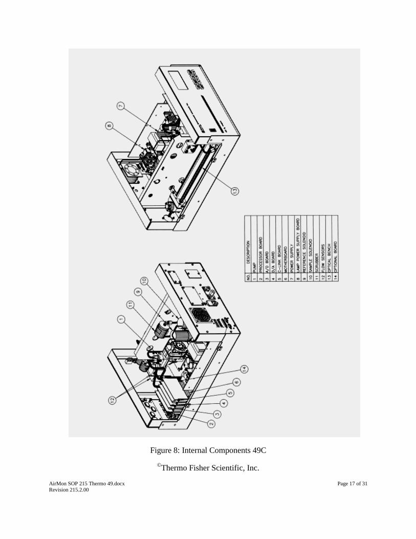
Figure 8: Internal Components 49C
©Thermo Fisher Scientific, Inc.

AirMon SOP 215 Thermo 49.docx Page 18 of 31 Revision 215.2.00
Figure 9: Internal Components 49i
©Thermo Fisher Scientific, Inc.
9.5.1 Procedure: Change Inlet Filter
An in-line Teflon filter protects the analyzer from dirt and contaminants. Filters should be
changed on a regular schedule. Use 10.0 Teflon filters.
1. Carefully open filter holder assembly;
2. Remove old filter, replace with new filter;
3. Carefully close filter holder assembly;
4. Enter the appropriate information into the DMS e-log for the instrument
9.5.2 Procedure: Cooling Fan Filter Servicing
1. Remove the fan guard from the fan and remove the filter.
2. Flush the filters with warm water and let dry (a clean, oil-free purge will help the drying
process) or blow the filters clean with compressed air.
3. Re-install the filter and fan guard.
4. Enter the appropriate information into the DMS e-log for the instrument
AirMon SOP 215 Thermo 49.docx Page 19 of 31 Revision 215.2.00
9.5.3 Procedure: Instrument Internal Cleaning
1. Carefully open instrument cover;
2. Vacuum the instrument interior;
3. Carefully blow out remainder of dust with compressed air;
4. Carefully replace instrument cover;
5. Enter the appropriate information into the DMS e-log for the instrument
9.5.4 Procedure: Capillary Inspection and Cleaning
1. Disable the appropriate DAS channel.
2. Turn the instrument OFF and unplug the power cord.
3. Remove the instrument cover.
4. Locate the capillary holder.
5. Remove the glass capillary and o-ring. Inspect o-ring for cuts or abrasion, and replace as
necessary.
6. Check capillary for particulate deposits. Clean or replace as necessary.
7. Replace capillary making sure the o-ring is around the capillary before inserting it into
the body.
8. Finger-tighten the capillary nut enough to ensure a tight seal.
9. Re-install the cover.
10. Re-enable the appropriate DAS channel.
11. Enter the appropriate information into the DMS e-log for the instrument
9.5.5 Procedure: External Pump Rebuild
Most stations use an external Thomas vacuum pump. The pump should be checked and re-built
annually or when flow/vacuum issues arise. The pump should pull at least 15 “Hg and be steady.
Other pumps may be used, in which case, refer to the instructions that are provided with the
pump rebuild kit. Noisy bearings should be replaced. Pumps that run hot, are excessively noisy,
or fail to deliver a steady vacuum should be replaced.
OPTIONAL: In order to decrease instrument down-time, the operator may elect to switch in a
new or rebuilt pump.
.
1. Disable the appropriate DAS channel.
2. Unplug pump; disconnect the ¼” line from the pump.
3. Place a mark on the pump head to indicate proper re-positioning.
4. Remove the 4 screws holing the pump top valve assembly; remove the top valve
assembly.
5. Remove and inspect the pump diaphragm. If cracked, hardened, torn or damaged, replace
diagram.
6. Remove valve plate assembly from the top valve plate, noting alignment.
7. Carefully inspect plate assembly. Remove the flapper valves and clean. Replace if
corroded or damaged. Inspect the gasket. Replace if damaged.
8. Replace the valve plate assembly to the top valve plate, noting alignment.
9. Replace the pump top valve assembly;
AirMon SOP 215 Thermo 49.docx Page 20 of 31 Revision 215.2.00
10. Clean out windings with compressed air.
11. Plug in pump. Check with vacuum gauge.
12. Re-connect the ¼” line to the pump.
13. Check/re-calibrate analyzer.
14. Re-enable the appropriate DAS channel.
15. Enter the appropriate information into the DMS e-log for the instrument
9.5.6 Procedure: Internal Pump Rebuild
1. Disable the appropriate DAS channel.
2. Remove the cover.
3. Unplug pump from power supply; disconnect the ¼” fittings from top of the pump.
4. Place a mark on the pump head to indicate proper re-positioning.
5. Remove the 4 screws holing the pump top valve assembly; remove the top valve
assembly.
6. Remove and inspect the pump diaphragm and valve plate. If cracked, hardened, torn or
damaged, replace diagram and valve plate.
7. Replace the pump top valve assembly;
8. Re-connect ¼” fittings to top of the pump
9. Plug in pump.
10. Check/re-calibrate analyzer.
11. Re-install the cover.
12. Re-enable the appropriate DAS channel.
13. Enter the appropriate information into the DMS e-log for the instrument
9.5.7 Procedure: Cell Cleaning
Best results are obtained when the optical bench is cleaned prior to recalibration. The cleanliness
of the bench should also be checked any time the detector frequencies drop below 65 kHz, since
one source of low output is light attenuation due to dirt in the cell. Dirt particulates are usually
effective ozone removers.
1. Disable the appropriate DAS channel.
2. Turn the instrument OFF and unplug the power cord.
3. Remove the instrument cover.
4. Loosen the knurled nut around the tube and carefully slide out each tube.
5. Push a piece of lens paper down the tube using a 1/4piece of Teflon® tubing so as not
to damage the tube. Use a cotton swab to clean the window surfaces through the holes
that the tube fits into.
6. Both absorption tubes are identical, so they can be replaced in either position.
7. Replacement of absorption cells is opposite to that of removal. Since the Model 49 is a
ratio instrument, and cleaning the absorption tubes does not affect the calibration, it is not
necessary to recalibrate the instrument every time the cells are cleaned.
8. Re-install the cover.
9. Re-enable the appropriate DAS channel.
10. Enter the appropriate information into the DMS e-log for the instrument

AirMon SOP 215 Thermo 49.docx Page 21 of 31 Revision 215.2.00
Figure 10: Optical bench assembly
©Thermo Fisher Scientific, Inc.
9.5.8 Procedure: Scrubber replacement
1. Disable the appropriate DAS channel.
2. Turn the instrument OFF and unplug the power cord.
3. Remove the instrument cover.
4. Loosen fittings on each end of scrubber.
5. Remove converter clamp from divider panel.
6. Remove scrubber.
7. Replace scrubber by following the above procedure in reverse. Make sure that the
converter tube ends have passed through the ferrule of the fitting and that the fittings are
tight.
8. Re-install the instrument cover.
9. Perform a leak test:
a. Disconnect the sample line and plug the sample fitting.
b. Disconnect the sample and zero-air input lines and plug.
c. Plug the ozone and vent outputs if the optional internal ozonator is installed.
d. The flows as displayed in the Flows screen of the Diagnostics menu should
slowly decrease to zero.
e. The pressure as displayed in the Pressure screen should drop to below 250 mm
Hg. If the pump diaphragm is in good condition and the capillary not blocked, it
should take less than 20 seconds from the time the inlet is plugged to the time of

AirMon SOP 215 Thermo 49.docx Page 22 of 31 Revision 215.2.00
reading below 250 mm Hg is achieved. Leaks can best be detected by carefully
tightening each fitting until the leak is found
f. Remove all plugs and reconnect all lines
10. Re-enable the appropriate DAS channel.
11. Perform zero/span verification.
12. Enter the appropriate information into the DMS e-log for the instrument
9.6 SAMPLE COLLECTION
NOTE: This SOP section is non-applicable and is left intentionally blank
9.7 SAMPLE HANDLING AND PRESERVATION
NOTE: This SOP section is non-applicable and is left intentionally blank
9.8 SAMPLE PREPARATION AND ANALYSIS
NOTE: This SOP section is non-applicable and is left intentionally blank
9.9 TROUBLESHOOTING
NOTE: Please refer to the appropriate THERMO Instrument Manual for further information.
NOTE: The operator should utilize the DMS to track and record various parameters (parametric
data) which may be helpful for troubleshooting.
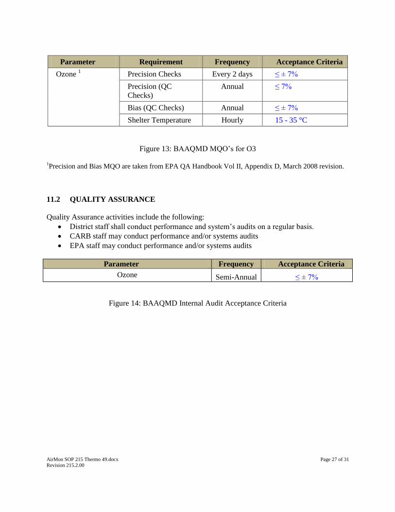
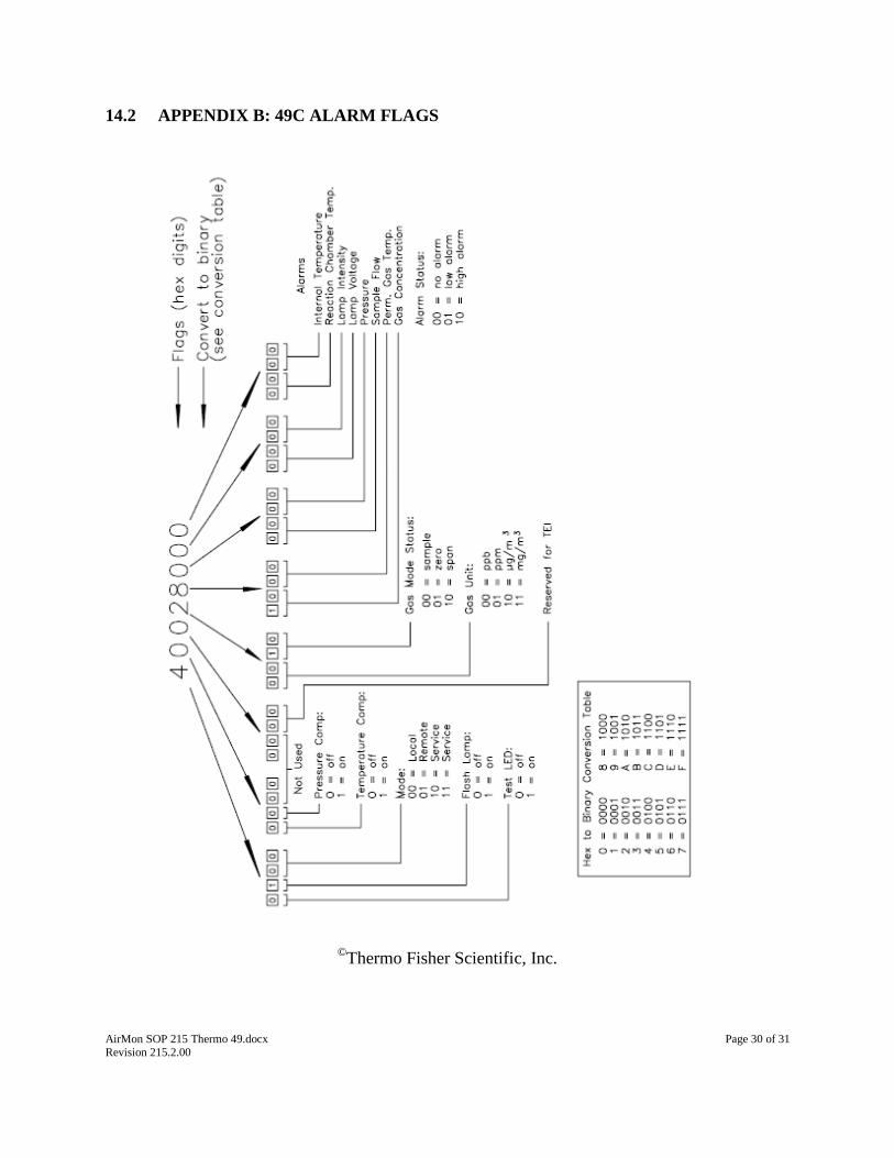
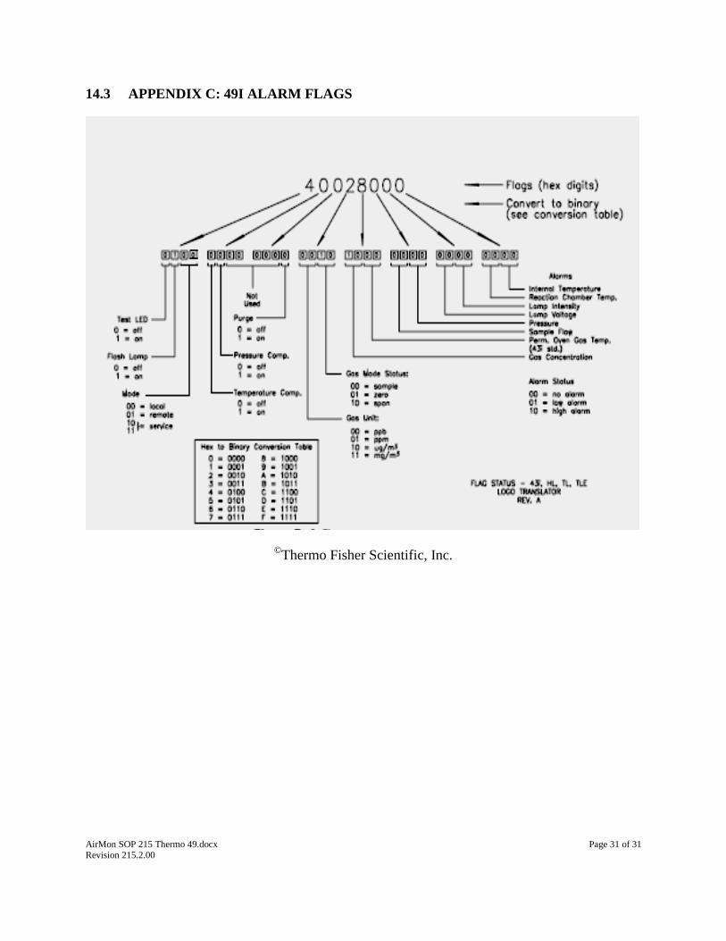
NOTE: 1-minute DMS data also includes instrument flags. For diagnostic flag codes, please
refer to Appendix B and Appendix C of this SOP.
The operator should be aware of the following:
Abnormal or out-of-range concentration values on instrument front display;
‘Alarm’ or alarm icon present on the analyzer front display;
Abnormal or out-of-range diagnostic’s values (i.e., flow, pressure, chamber temperature,
frequency, etc.);
Abnormal or out-of-range DAS or DMS parametric data (i.e., flow, pressure, chamber
temperature, frequency, etc.);
Abnormal DAS or DMS instrument diagnostic flags;
Abnormal or unusual auto calibration and/or manual calibration results;
Unusual sounds (pump, kicker pump, etc.)
The operator should take the appropriate steps to resolve any instrument issue:

AirMon SOP 215 Thermo 49.docx Page 23 of 31 Revision 215.2.00
Troubleshoot to identify faulty component or support equipment
Repair instrument or support equipment;
Check and verify instrument’s performance; re-calibrate if needed;
Review and invalidate any data that does not meet the criteria in Section 11 of this SOP;
Review and validate or invalidate any questionable data as ‘suspect’;
Maintain the appropriate DMS instrument and/or station e-log. The operator must enter
the appropriate information after the completion of any repairs, maintenance, or
adjustments. The operator should note any data gaps.
In cases of instrument failure or inability to repair on-site, the operator should contact the
Senior AQIS and/or the Supervising AQIS in order to coordinate replacement of the
instrument.
SYMPTOM: Significantly lower response during calibration checks from previous check
An indication of sample/reference solenoid malfunction
To check, run an O3 span and view Diagnostics A/B to get dual display. If either the “A”
or “B” is significantly and repeatedly lower than the other, one of the solenoids is
internally leaking across the ports.
o Reference solenoid is toward the front
o Remove the solenoid plate assembly and test; Use bubble test to check for leaks in
solenoid. Pump air into side port and have the common blowing into the water.
o Also pump air across the side ports to check for leaks. Check other port by
energizing solenoid.
o Replace both solenoids especially if they have been in service several years.
SYMPTOM: ozonator lamp does not light
(49C): The 3000uf capacitor (C-12) on the ozonator power supple may be leaky or have
failed. This capacitor affects the raw 24v for the ozonator lamp as well.
o Check voltage from pin 2 to ground on J3, voltage should be around 24 volts. An
open or leaky condition in this capacitor will cause the 24v value to drop.
o The ozonator power supple voltages should be 17.5 to 18.0 volts from 18.0 volt
regulator.
o At lamp start, voltage may be as low as 15.5 but should increase to near 18.0v as
the lamp heater warms up.
(49C): Top horizontal board above the other boards is for power to the ozonator
generator. Lower board in back of analyzer is the lamp power supply (photometer lamp
power supply) board.
Install a new photometer lamp by inserting it all the way in and backing it out 1/8 to ¼
inch. Maximize frequencies by rotating the lamp.
SYMPTOM: (49C): Ozone SPAN COEF above 1.050
Pressure transducer may need to be calibrated. Obtain true barometric pressure in mm of
mercury. Disconnect surgical tubing and note analyzer pressure display. It will usually
be low, adjust span screw to bring pressure value up to the true value. Reconnect tubing
and display should drop to a negative value indicating vacuum from the pump. Turning

AirMon SOP 215 Thermo 49.docx Page 24 of 31 Revision 215.2.00
off the pressure/temp transducer should cause a significant change in the analyzer
response.
SYMPTOM: Flow
Check capillaries and o-rings;
o To clean capillaries use wire cat whiskers and distilled water. Compressed air
will also work.
o Replace any worn or cracked o-rings. Do not use vacuum grease!
Check pump if capillaries and o-rings are OK
OTHER:
(Models that have ozone generators in use). External zero air scrubber flow path:
pump outlet to Purafil end of cylinder, exit from charcoal end to “zero air in” at rear
of THERMO 49. Purafil oxidizes NO into NO2 and the charcoal scrubs the NO2
from the air stream.
o (Ozone generator). Check regulator flow pressure by switching the flow on and
off. Check for restricted flow in the ozonator capillary.
Condition new catalytic converter by running high span ozone through it for at least an
hour before attempting to calibrate analyzer.
Do not use contact cleaner on any of the circuit boards, it affects the gold contacts. Use
Pro-Gold only.
Following start up wait 5–10 minutes for the unit to complete the restart sequence.
Analyzer will not start until lamp is lit and lamp heater block is up to temperature.
o Flow:
Heavy fog and dew may reduce the scrubber efficiency which in turn will reduce
analyzer response to ozone concentration.
Multiblend cylinders with SO2 will have some SO3 radicals present which will be seen
as 3-11 ppb of O3 when the calibrator has gas flowing out of the output.
A cabinet cooling (muffin) fan failure can cause ozonator output to increase even if
shelter temperature is within the usual range. Check for fan failure if ozonator output
shifts up to a higher value during auto cal checks especially at precision level.
9.10 COMPUTER HARDWARE AND SOFTWARE
The Model 49 is connected to a BAAQMD station DAS via its Serial RS-232 Port. The DAS
collects 1-minute data. All 49i instrument parameters must be set accordingly. No further data
calculations or reduction are required.
DAS: The operator should be familiar with operation of the station’s DAS and the DAS
manual calibration script files
DMS: Operator should be familiar with the operation of the DMS software including data
review, auto-cal response data review, e-log entry, etc.
iPort: The operator should be familiar with the use of THERMO iPort software
AirMon SOP 215 Thermo 49.docx Page 25 of 31 Revision 215.2.00
10. DATA AND RECORDS MANAGEMENT
1-minute concentration data (ppm) is collected by the station’s DAS. The station DAS
pushes data hourly to the BAAQMD DMS. Data is retained by the DMS for future
review and usage.
1-minute analyzer parametric data are collected by the station’s DAS. The station DAS
pushes data hourly to the BAAQMD DMS. Data is retained by the DMS for future
review and usage.
Analyzer parametric data may include various instrument operating parameters such as
flow rate, pressure, lamp temperature, instrument flags (please refer to the appropriate
THERMO instrument manual and Appendix B and C of this SOP for an explanation of
diagnostic flags), etc. The operator is encouraged to use the instrument parametric data as
an aid to data review and validation and for troubleshooting
District staff are responsible for data and records management including oversight of data
capture into a station DAS, data ingestion into the District DMS, data review and
validation, and data retention.
The operator is responsible for the following:
Review and validate or invalidate any data that does not meet the criteria in Section 11 of
this SOP
Review and validate or invalidate any questionable data flagged as ‘suspect’
Maintain the appropriate DMS instrument and/or station e-log. The operator must enter
the appropriate information after the completion of any repairs, maintenance, or
adjustments. The operator should note any data gaps. The operator may elect to manually
collect data from the analyzer in the event of a DAS data collection error.
11. QUALITY CONTROL AND QUALITY ASSURANCE
Quality Control (QC) procedures include the completion of any required calibrations, service and
maintenance. Quality Assurance (QA) procedures include the completion of any required audits.
11.1 QUALITY CONTROL
The operator shall perform all recommended or required diagnostic checks, service and
maintenance. Please refer to Section 9.5 of this SOP and the appropriate instrument
manual for more information. Note in the appropriate e-log all checks, service and
maintenance made to the analyzer or support equipment!
Zero, span, mid-low span, mid-high span, and precision level auto-cals are automatically
run nightly, alternating between the various auto-cals. If an auto-cal measurement is
outside the specified QC (quality control) limit, the source of the problem is to be
investigated and corrected. The operator will then adjust the analyzer by running a

AirMon SOP 215 Thermo 49.docx Page 26 of 31 Revision 215.2.00
manual zero or span calibration. Note in the appropriate e-log all repairs, maintenance or
adjustments made to the analyzer or support equipment!
NOTE: QC limits are developed to provide an early warning of instrument problems
prior to the exceedance of a Measurement Quality Objective (MQO). Violation of a QC
limit does not require data action as long as an MQO is not also exceeded.
NOTE: Do not adjust the analyzer while running a precision! The operator may only
adjust the analyzer by running a zero and span, followed by another precision. Note in the
appropriate e-log all adjustments made to the analyzer!
If any MQO’s are exceeded, the source of the problem is to be investigated and corrected
and the operator shall invalidate all suspect or questionable 1-minute DMS data unless
the error is a result of other equipment (i.e., malfunctioning calibrator, power-failure,
etc.) and the operator has demonstrated that the instrument is functioning within its
specified operating parameters.
Hourly DMS data are manually invalidated by MQA if the station/shelter temperature
range exceeds instrument certification limits. Data invalidations due to station
temperature excursions are managed manually by MQA on a case-by-case basis per
guidelines documented in Data Management SOP 601.
Parameter Instrument EPA Required Temp
Range
BAAQMD Station/Shelter Out Of
Range Criteria
Ozone Thermo 49
(all)
20 -30 °C ≤ 19.5 °C or ≥ 30.5 °C
Figure 11: BAAQMD Station/Shelter Temperature Criteria
NOTE: Operator should include comments regarding shelter temperatures, sensors, controls,
etc. in DMS e-logs. Data quality/validity resolution resides with MQA.
NOTE: Ambient data correction and adjustment will be performed on hourly data only, by
MQA, with justification provided by AQIS (i.e. pump pressure shifts, instrument adjustment,
data shift or data drift caused by instrument component failure).
Parameter Requirement Frequency Acceptance Criteria
Ozone Precision Check Every 2 days ≤ ± 5%
Zero/Span Check Every 2 days ≤ ± 3 ppb Zero
≤ ± 3% Span diff
Bias Validation Annual 95% of PE points fall
within
95% PL for QC Checks
Figure 12: BAAQMD QC Limits for O3
AirMon SOP 215 Thermo 49.docx Page 27 of 31 Revision 215.2.00
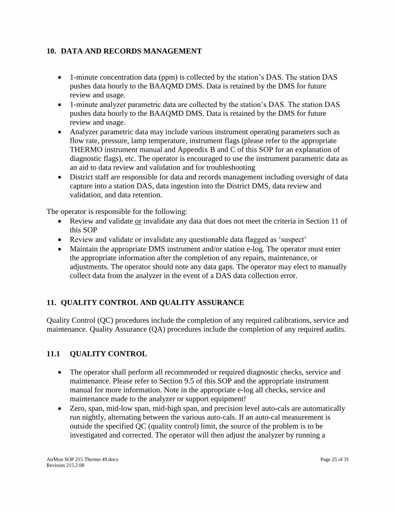
Parameter Requirement Frequency Acceptance Criteria
Ozone 1 Precision Checks Every 2 days ≤ ± 7%
Precision (QC
Checks)
Annual ≤ 7%
Bias (QC Checks) Annual ≤ ± 7%
Shelter Temperature Hourly 15 - 35 °C
Figure 13: BAAQMD MQO’s for O3
1Precision and Bias MQO are taken from EPA QA Handbook Vol II, Appendix D, March 2008 revision.
11.2 QUALITY ASSURANCE
Quality Assurance activities include the following:
District staff shall conduct performance and system’s audits on a regular basis.
CARB staff may conduct performance and/or systems audits
EPA staff may conduct performance and/or systems audits
Parameter Frequency Acceptance Criteria
Ozone Semi-Annual ≤ ± 7%
Figure 14: BAAQMD Internal Audit Acceptance Criteria

AirMon SOP 215 Thermo 49.docx Page 28 of 31 Revision 215.2.00
12. AUTHORS
Original Author: Morris Erickson
Revised By: Stan Yamaichi, 5/30/2008
Revised By: Christopher Rumm, 06/20/2012; re-formatted SOP; added THERMO ‘i’
Model information
13. REFERENCES
Code of Federal Regulations, Title 40, Part 53
Code of Federal Regulation, Title 40, Part 58
EPA QA Handbook Vol. II, Quality Assurance Handbook for Air Pollution Measurement
Systems
EPA Air Quality Standards, 40 CFR Part 50, NAAQS for Criteria Pollutants
Thermo Fischer Scientific, Inc. Instrument Manual: \\cifs-
02\sections\Air_Mon\Instrument Manuals\THERMO
Data Mgt SOP 601 Gaseous Pollutants

AirMon SOP 215 Thermo 49.docx Page 29 of 31 Revision 215.2.00
14. APPENDIXES
14.1 APPENDIX A: 49 SPECIFICATIONS
SPECIFICATIONS YELLOW = RECOMMENDED SETTING
Preset ranges: 0-0.05, 0.1, 0.2, 0.5, 1, 2, 5, 10, 20, 50, 100, 200 ppm
Zero noise: 0.25 ppb RMS (60 second averaging time)
Lower detectable limit: 1.0 ppb
Zero drift: < 1 ppb/24 hour; < 2 ppb/7 day
Span drift: < 1% per month (including drift of transducers)
Response time: 20 seconds (10 seconds lag time)
Linearity: ± 1% of full-scale
Sample flow rate: 1–3 LPM
Operating temperature: 20–30 °C (may be safely operated over the range of 0–45 °C)*
Power requirements: 100 VAC @ 50/60 Hz; 115 VAC @ 50/60 Hz; 220-240 VAC @
50/60 H 150 watts
Physical dimensions: 16.75” (W) X 8.62” (H) X 23” (D)
Weight Approximately: 35 lbs.
Serial Ports: 1 RS-232 or RS-485 with two connectors, baud rate 1200–115200,
data bits, parity, and stop bits, protocols: C-Link, MODBUS, and
streaming data (all user selectable)
Ethernet connection RJ45 connector for 10Mbs Ethernet
connection, static or dynamic TCP/IP addressing *In non-condensing environments.
AirMon SOP 215 Thermo 49.docx Page 30 of 31 Revision 215.2.00
14.2 APPENDIX B: 49C ALARM FLAGS
©
Thermo Fisher Scientific, Inc.
AirMon SOP 215 Thermo 49.docx Page 31 of 31 Revision 215.2.00
14.3 APPENDIX C: 49I ALARM FLAGS
©Thermo Fisher Scientific, Inc.