title of dissertation goes here in all caps · conventionally used thin metallic films on...
TRANSCRIPT

Doctoral Thesis
by
EVGENIA P. GILSHTEYN
Doctoral Program in Materials Science and Engineering
COMPONENTS FOR STRETCHABLE ELECTRONICS BASED ON
SINGLE-WALLED CARBON NANOTUBES
Supervisor
Professor Dr. Sc. Albert G. Nasibulin
Moscow - 2018
© Evgenia Gilshteyn 2018

2
Abstract
Wearable and stretchable electronics is urgently developing field of engineering
and applied physics, which requires novel forms of conductors as the essential device
components. Despite advances in the performance of existing classes of wearable
electronic devices and miniaturization of wearable integrated circuits, mechanical design
in wearable technology remains conceptually old: brittle components and bulky devices
are encapsulated in elastomeric packaging. Conventionally used thin metallic films on
elastomeric substrates can accommodate strain (less than 10%) by means of controlled
fracture or buckling and they are generally opaque. Conductive polymers can be buckled
to form stretchable transparent electrodes, but topographic buckles may be incompatible
with devices that require planar interfaces. Thus, new materials are required for
transparent, conductive and highly stretchable electrodes.
Electronics based on nanomaterials have been attracting interest recently due to
their strain sensing characteristics. However, along with the sensitivity during stretching
stable performance of the whole device or system is needed. Here, we report about thin
films of single-walled carbon nanotubes (SWCNTs), which can be used as the key
component of different electronic devices. The electrical and optical properties of these
devices can exhibit excellent characteristics due to a combination of high elastic moduli
and outstanding optoelectrical properties of the SWCNTs.
We fabricated various devices and systems, where SWCNTs-based structures play
role of passive and active parts of electronic circuit: stretchable electrically conductive
hydrogels and poly(dimethylsiloxane) (PDMS) electrodes, strain sensors, highly
stretchable and flexible supercapacitors and piezo-supercapacitor systems based on them.
Firstly, the stretching mechanism of SWCNT/PDMS structures (i.e., SWCNT thin films
deposited on PDMS substrate) were investigated by means of in situ scanning electron
microscopy (SEM) and compared with the computational studies. Highly transparent,
electrically conductive, stretchable structures of tough hydrogels modified by SWCNTs
were applied as skin-like passive electrodes and active finger-mounted joint motion
sensors. Stretchable all-solid supercapacitors based on SWCNTs have been successfully
stretched up to 120% with practically no variation in the electrochemical performance

3
after 1000 stretching cycles and 1000 charging–discharging cycles. High-performance,
stable, low equivalent series resistance all-nanotube stretchable supercapacitor based on
SWCNTs film electrodes and a boron nitride nanotube separator demonstrates
electrochemical double layer capacitance mechanism in a two-electrode test cell
configuration and retains 96% of its initial capacitance after more than 20 000
electrochemical charging/discharging cycles and withstands at least 1000 cycles of
stretching with low resistance of 250 Ω. Finally, integration of such supercapacitors into
a flexible piezo-supercapacitor system with poly(vinylidene-trifluoroethylene) film to
harvest and store the energy was also demonstrated. An open circuit voltage of the flexible
and transparent supercapacitor reached 500 mV within 20 s during the mechanical action,
which allow us to further extend it for providing sustainable power source of various types
of sensors integrated into wearable units.
The stretchable, transparent SWCNT based components and devices were
prepared without dispersion in an elastic matrix, without time consuming and expensive
lithographic techniques and patterned simply using dry transfer method. In the future, it
could be possible to use these principles, materials and devices to design electronics that
“echo and imitate the natural world by bending, stretching and flexing” and make sense
as technology integrated more and more into our lives, our environments, and even our
bodies.
4
List of publications
1. Evgenia Gilshteyn, Albert G. Nasibulin, Aerosol synthesized carbon nanotube films for
stretchable electronic applications, Proceedings of the 15th IEEE International
Conference on Nanotechnology, 978-1-4673-8156-7, 893-896 (2015).
2. Evgenia P. Gilshteyn, Tanja Kallio, Petri Kanninen, et al., Stretchable and Transparent
supercapacitors based on aerosol synthesized carbon nanotube films, RSC Advances, 6,
93915-93921 (2016).
3. Evgenia P. Gilshteyn, Daler Amanbayev, Anton S. Anisimov, Tanja Kallio & Albert G.
Nasibulin, All-nanotube stretchable supercapacitor with low equivalent series resistance,
Scientific Reports, 7, 17449 (2017).
4. Evgenia P. Gilshteyn, Daler Amanbaev, Maxim V. Silibin, Artem Sysa, Anton S.
Anisimov, Tanja Kallio, Albert G. Nasibulin, Flexible self-powered piezo-supercapacitor
system for wearable electronics, Nanotechnology, 29, 325501 (2018).
5. Evgenia P. Gilshteyn, Shaoting Lin, Vladislav A. Kondrashov, Daria S. Kopylova,
Alexey P. Tsapenko, Anastasios J. Hart, Xuanhe Zhao, Albert Nasibulin, A one-step
method of hydrogel modification by single-walled carbon nanotubes for highly stretchable
and transparent electronics, ACS Applied Materials & Interfaces, 10, 33, 28069-28075
(2018).
6. Evgenia Р. Gilshteyn, Georgy Savostyanov, Stepan Romanov, Daria S. Kopylova,
Artem Zyktin, Anton S. Anisimov, Olga E. Glukhova, Albert G. Nasibulin, Strain-induced
properties of single-walled carbon nanotube films on PDMS substrates, submitted to ACS
Nano (2018).

5
Other featured publications 1. Laura Martínez-Sartia,Pertegása, María Monrabal-Capilla, Evgenia P. Gilshteyn, et
al., Flexible light-emitting electrochemical cells with single-walled carbon nanotube
anodes, Organic Electronics, 30, 36–39 (2016).
2. Alexandra L. Gorkina, Alexey P. Tsapenko, Evgenia P. Gilshteyn et al., Transparent
and conductive hybrid graphene/carbon nanotube films, Carbon, 100, 501-507 (2016).
3. Partha P Pal, Evgenia Gilshteyn, Hua Jiang, Marina Timmermans, et.al., Single-
walled carbon nanotubes coated with ZnO by atomic layer deposition, Nanotechnology,
27, 485709 (2016).
4. Zhukova E. S., Grebenko A. K., Bubis A. V., Prokhorov A. S., Belyanchikov M. A.,
Tsapenko A. P., Gilshteyn E. P., Kopylova D. S., Gladush Y. G., Anisimov A. S., Anzin
V. B., Nasibulin A. G. and Gorshunov B. P., Terahertz-infrared electrodynamics of single-
wall carbon nanotube films, Nanotechnology, 28, 445204 (2017).
5. Pramod M Rajanna, Evgenia P. Gilshteyn, Timur Yagafarov, Alena K. Aleekseeva,
Sergey Anisimov, Alex Neumüller, Oleg Sergeev, Sergey Bereznev, Jelena Maricheva,
Albert G. Nasibulin, Enhanced efficiency of hybrid amorphous silicon solar cells based on
single-walled carbon nanotubes and polymer composite thin film, Nanotechnology, 29,
105404 (2018).
6. Kopylova D.S., Fedorov F., Alekseeva A., Gilshteyn E., Tsapenko A., Bubis A.,
Grebenko A., Popov Z., Sorokin P., Anisimov A., Nasibulin A., Holey Single-Walled
Carbon Nanotubes for Ultra-Fast Broadband Bolometers, Nanoscale, 2018, Accepted
Manuscript.
7. Maria A. Zhilyaeva, Eugene V. Shulga, Ivan V. Sergeichev, Evgenia P. Gilshteyn,
Anton S. Anisimov, Albert G. Nasibulin, A novel straightforward wet pulling technique
to fabricate carbon nanotube fibers, submitted to Advanced Materials.
8. Mehrabimatin B., Gilshteyn E., Buan M. E., Sorsa O., Jiang H., Zad A. I., Shahrokhian
S., Kallio T., Nasibulin A., Highly performing NiCo layered double hydroxide and
nitrogen-doped graphene based flexible supercapacitor for wearable energy storage,
submitted to ACS Appl. Mater. Interfaces.

6
Acknowledgements
I express my sincerest gratitude to my supervisor, Professor Albert Nasibulin for
sharing his expertise, support and professional attitude. Thanks for belief in me and for
making me the first student of your lab four years ago.
I show my greatest appreciation to Professor Tanja Kallio. This thesis would
hardly be possible without her insights and guidance.
My gratitude is extended to each and every member of the Laboratory of
Nanomaterials. Stepan Romanov you are a true friend and best lab mate. Dr. Vladislav
Kondrashov, it was a true pleasure to have your support and work with you. My special
thank is to the former Lab members: Alexandra and Daler, you are true friends to forever.
I thank all our collaborators and co-authors for your help with experimental work
as well as publications preparation and revision.
I owe my deepest gratitude to my mum and my husband, Elvira and Vitalii, your
trust and support is everything to me. My Grandma Zina, you were extremely supportive
during the whole study period. Special thanks to my Grandpa Jakov: I did it to dispel your
doubts.
This work was supported by Skoltech NGP Program (Skoltech-MIT joint
project). Moreover, I thank the Russian Science Foundation for financial support of the
synthesis and characterization of the fabricated structures (Agreement No. 17-19-01787).

7
Contents
Abstract ................................................................................................................................................. 2
List of publications .............................................................................................................................. 4
Other featured publications .............................................................................................................. 5
Acknowledgements ............................................................................................................................. 6
Abbreviations ....................................................................................................................................... 9
List of Figures .................................................................................................................................... 10
List of Tables ...................................................................................................................................... 12
Chapter 1. Introduction and related work ................................................................................... 13
Chapter 2. Materials and Methods ................................................................................................ 17
2.1 Aerosol SWCNT synthesis and film deposition ............................................................. 17
2.2 Fabrication of stretchable elastomers ............................................................................... 19
2.2.1 PDMS substrates .............................................................................................................. 19
2.2.2 Tough hydrogels ................................................................................................................ 19
2.2.3 PVA-gel electrolyte ............................................................................................................ 20
2.3 Electrical and optical measurements ................................................................................. 20
2.4 TEM and SEM techniques .................................................................................................. 21
2.5 SWCNT/hydrogel structures integration ....................................................................... 21
2.6 Electrochemical characterization of the supercapacitors .............................................. 22
2.7 Coarse-grained molecular dynamics for theoretical modeling .................................... 22
Chapter 3. Results and discussion ................................................................................................. 23
3.1 Strain-induced properties of SWCNT films on PDMS substrates ............................ 23
3.1.1 Two approaches of SWCNT films transfer from a filter onto PDMS ....................... 23
3.1.2 Investigation of the SWCNT films morphological changes while stretching .............. 24
3.1.3 Electrical properties of the SWCNT/PDMS structures and its computational
modeling ....................................................................................................................................... 27
3.1.4 Application of the proposed approach to the commercially available SWCNTs .......... 29
3.2 A one-step method of hydrogel modification by SWCNTs ......................................... 31
3.2.1 SWCNT film deposition process on a hydrogel surface ................................................. 32

8
3.2.2 Characterization of SWCNT/hydrogel structures obtained on the as-prepared
hydrogel ........................................................................................................................................ 32
3.2.3 Characterization of SWCNT/hydrogel structures obtained on the pre-stretched
hydrogel ........................................................................................................................................ 35
3.2.4 Applications of SWCNT/hydrogel structures ................................................................ 38
3.3 Stretchable and transparent supercapacitors based on SWCNT films ..................... 40
3.3.1 TSS based on liquid H2SO4/separator ........................................................................... 41
3.3.2 TSS based on a PVA-H2SO4 gel electrolyte ................................................................... 44
3.3.3 TSS based on a PVA-H2SO4 gel electrolyte and pre-stretching approach ................... 46
3.4 Flexible self-powered piezo-supercapacitor system for wearable electronics .......... 47
3.4.1 Fabrication and characterization of flexible supercapacitor ......................................... 48
3.4.2 Assembly of the piezo-supercapacitor system and measurements of its self-charging
performance.................................................................................................................................. 50
3.5 All-nanotube stretchable supercapacitor with low equivalent series resistance ..... 54
3.5.1 Two-electrode cell and electrochemical measurements ................................................... 55
3.5.2 Fabrication of the all-nanotube SWCNT/BNNT stretchable supercapacitor
prototype ....................................................................................................................................... 57
3.5.3 Characterization of all-nanotube SWCNT/BNNT stretchable supercapacitor ........ 58
Conclusions ......................................................................................................................................... 65
Bibliography ....................................................................................................................................... 67

9
Abbreviations
BNNT – boron nitride nanotube
CGM - coarse-grained modeling
CV – cyclic voltammetry
CVD - chemical vapor deposition
DC – direct current
DMA - differential mobility analyzer
DMF – dimethylformamide
ECG – electrocardiography
ECH - electrically conductive hydrogel
EDLC – electrical double-layer capacitor
EIS – electrochemical impedance spectroscopy
ESR – equivalent series resistance
FET – field-effect transistor
GCD – galvanostatic charge-discharge
IPA – isopropanol
ITO – indium tin oxide
LED – light emitting diode
PDMS - poly(dimethylsiloxane)
PET – polyethylene terephthalate
PVA – polyvinyl alcohol
P(VDF-TrFE) - poly[(vinylidenefluoride-co-trifluoroethylene]
SEM – scanning electron microscopy
SSC - stretchable supercapacitor
SWCNT – single-walled carbon nanotube
TEM – transmission electron microscopy
TS - transparent and stretchable
TSS – transparent stretchable supercapacitor
XRD - X-ray diffraction

10
List of Figures
Figure 1. A “lab-on-skin”: stretchable and flexible devices for measuring body
parameters……………………………………………………………………………….. 14
Figure 2. Several approaches to achieve TS components ........................................................ 15
Figure 3. SEM and TEM images of aerosol synthesized SWCNT film. ............................ 18
Figure 4. Dry process of SWCNTs film deposition/transfer on PDMS substrate. ......... 19
Figure 5. Photographs of the (from left to right): SWCNT/PDMS test samples with silver
paste contacts, SEM stage Gatan 200N and homemade stretching device with the
structures fixed under the clips. .................................................................................................... 21
Figure 6. Generic illustration of a) two operational modes of SWCNTs during stretching;
b) SWCNT film deposition process realized by two dry transfer approaches: on the as-
prepared PDMS and on the pre-stretched PDMS. .................................................................. 24
Figure 7. Characterization of SWCNT/PDMS structures prepared by film deposition
onto the as-prepared PDMS. SEM images of the structures at different strains. Changes
in the SWCNTs orientations calculated for the local gradients of intensity from SEM
images of the structures stretched to different strains...........…………………………… 26
Figure 8. SEM images of the films prepared according to the pre-stretching approach.
Electrical properties of SWCNT films deposited on pre-stretched PDMS. ...................... 27
Figure 9. Resistance change of SWCNT film: a) on as-fabricated PDMS (15 cycles of
stretching to a certain strain value); b) on PDMS trained to 100% before stretching.
Coarse-grained model (CGM) of SWCNTs stretching: c) Simulated morphology and d)
Theoretically predicted resistance change of SWCNT film on PDMS………………… 29
Figure 10. SEM images of the SWCNT films fabricated from water dispersion on the as-
prepared PDMS substrate: a) initially without any strain applied; b) 10% strain applied
leading to the appearance of micro cracks, c) 30% strain increasing the density of the
cracks; d) overview of the film morphology after the strain release.… ............................... 30
Figure 11. Photographs of tough hydrogel and SWCNT/hydrogel structures at the
stretched states demonstrating its high transparency ............................................................ 32

11
Figure 12. Characterization of SWCNT/hydrogel structures prepared by deposition onto
the as-prepared hydrogel ................................................................................................................ 34
Figure 13. Trend in the transmittance change while applying and releasing the strain for
the SWCNT/hydrogel structures prepared by a simple dry transferring technique ...... 34
Figure 14. Optical properties of the tough hydrogel ............................................................... 35
Figure 15. Characterization of SWCNT/hydrogel structures prepared by deposition onto
the pre-stretched hydrogel ............................................................................................................. 36
Figure 16. Comparison between experimental results and theoretical prediction for the
relative resistance change of the SWCNT/hydrogel structures .......................................... 38
Figure 17. Application of SWCNT/hydrogel structures as active components: a)
biocompatible strain-sensors for a human motion detection ................................................. 39
Figure 18. Application of SWCNT/hydrogel structures as passive electrodes ................. 40
Figure 19. Scheme of TSS fabrication process .......................................................................... 42
Figure 20. Electrochemical characterization of the SWCNT stretchable supercapacitors
with acid H2SO4 ................................................................................................................................ 43
Figure 21. Cyclic voltammorgams of TSS with liquid acidic electrolyte at different periods
of time. ................................................................................................................................................ 43
Figure 22. The optical and electrochemical properties of gel electrolyte TSSs ................ 45
Figure 23. Characterization of gel electrolyte-based supercapacitor fabricated on pre-
stretched SWCNTs on PDMS ...................................................................................................... 46
Figure 24. Characterization of the flexible gel-based supercapacitor .................................. 49
Figure 25. Electrochemical performance of the supercapacitors device with
PVA/H2SO4 gel electrolyte ....................................................................................................... 50
Figure 26. Characterization of the built piezo-supercapacitor system during the
mechanical action testing by a “motorized hand” .................................................................... 52
Figure 27. Self-charging performance of piezo-supercapacitor system ............................... 53
Figure 28. Schematic two-electrode cell assembly process ..................................................... 57
Figure 29. Process flow of stretchable supercapacitor fabrication ...................................... 58
Figure 30. SEM images of the separator layer .......................................................................... 59
Figure 31. Electrochemical performance of the two-electrode test cell .............................. 60
Figure 32. Stretchable BNNT-based supercapacitor characteristics ................................... 61

12
List of Tables Table 1. Comparison between main properties of electrically conductive hydrogels with
different fillers and SWCNT/hydrogel structures .................................................................. 26
Table 2. Parameters, calculated for all-nanotube supercapacitors: two-electrode cell
assembly and stretchable prototype ............................................................................................. 56

13
Chapter 1. Introduction and related work
The development of stretchable and transparent electronics is mostly inspired by
the nature and is becoming promising area for next generation of “smart” wearable
electronic devices. Among such stretchable electronic devices are those which mimic
functions of living species (human [1], animal [2], and even plant [3]) sensing such as
artificial skin or muscles [1, 2, 4-8], artificial electronic implants [9, 10], smart
prosthetics [11] have been recently developed. Such stretchable and transparent
electronics inspired by the nature are promising for huge range of applications in soft
robotics, healthcare, human monitoring, human-machine interfaces, and implantable
medical systems.
Transparent and stretchable (TS) electronics enable a broad range of new
applications such as TS circuits, touch displays and sensors where high transparency and
conductivity as well as fully independent operation at large mechanical strain are
simultaneously required. Such technological features will allow conformal placement of
devices and components on the human skin or any other curved and complicated surface,
as well as improve secure operation in consumer electronics applications. Polymers
represent the most promising platforms for integration of TS conductors due to their
inherent low mechanical stiffness. By present time, numerous soft, flexible and stretchable
devices build on polymeric substrates have emerged as platforms capable of digitizing
biological signals for healthcare monitoring, which is called “lab-on-skin” [12]. The
underlying concept is that these “lab-on-skin” devices can noninvasively measure most of
the biometrics required for health monitoring and disease diagnosis. Figure 1 [13] shows
examples of soft electronic interfaces located at different places on the human body and
developed for both monitoring and measuring such physiological parameters, as
temperature, hydration, blood pressure, blood oxygen level, skin mechanics, wound-
healing, electrophysiology, and various biomarkers in sweat.

14
Figure 1. A “lab-on-skin”: stretchable/flexible devices for measuring body parameters
[12].
However, the methods of new materials for novel electronics development and
processing exhibits several challenges. The fabrication of such TS devices could be
implemented by two different approaches: (i) geometric engineering of the materials on
TS substrates to fabricate TS electronic devices [14-16], and (ii) directly depositing
intrinsically transparent and stretchable materials on TS substrates to generate TS
electronic devices [17]. The first approach allows to fabricate high performance,
stretchability, and stability under mechanical deformation of the TS devices. However,
there are several disadvantages such as a complicated fabrication processes, stretching in
specific directions only, low device density, low production yield, high cost, and difficulty
in manufacturing in general. Some of these disadvantages can be solved by the integration
of the intrinsically TS materials, which is possible in frames of second approach. However,
the electrical response of the devices in frames of second approach is unstable under

15
mechanical strain applied. Moreover, it is hard to manufacture intrinsically TS materials
(conductors, insulators, and semiconductor materials). Therefore, it is still big unsolved
issue of TS electronic devices creation, which would be characterized by high performance,
high stretchability, stability, and a simple fabrication process. At the meantime, the TS
components include TS conductors, semiconductors, and insulators (Figure 2).
Figure 2. Several approaches to achieve TS components [17].
Transparent conductors are key building blocks for the development of TS
electrodes and interconnects, which are the basis of various “lab-on-skin” and other
stretchable devices. Films of carbon nanomaterials, such as SWCNTs, have attracted
numerous research interests in this area because (1) the long mean-free path of charge
carriers in defect-free films results in high conductivity, without the significant decrease
of the transparency, and (2) networks of carbon nanomaterials permit elasticity without
destroying the structure of the film. SWCNTs are a unique family of carbon-based
materials exhibiting exceptional thermal, electronic and mechanical properties, such as
excellent electrochemical stability, well-defined one-dimensional structure, low mass

16
density, high mechanical strength and high specific area. As it was already mentioned,
SWCNTs can be easily deposited from filter onto practically any substrate and in this case
such preparation method is very simple and can be done in a second time scale. For testing
flexibility, the CNT films were deposited on a PET substrate, which was bent around 30
000 times with the curvature radius of 1 mm and demonstrated very high stability of
SWCNT films. Due to the properties mentioned above, SWCNTs serve as good
alternatives for developing new era of stretchable electrodes and sensors.

17
Chapter 2. Materials and Methods
2.1 Aerosol SWCNT synthesis and film deposition
All carbon nanotubes (CNTs) synthesis methods can be divided into two major
groups: physical and chemical techniques based on the carbon atomization. Physical
methods can be characterized by high energy input to the carbon source, such as arc-
discharge, laser or induction heating evaporation. Chemical methods are based on the
CNTs growth due to the decomposition of carbon containing precursors. The obvious
advantage of this method, which can be implemented in a lab-scale, is the production of
the CNTs at relatively low temperatures. The chemical methods can be further divided
into substrate chemical vapor deposition (CVD) and aerosol (floating catalyst) CVD
syntheses. After the synthesis and collection on a nitrocellulose filter, CNTs can be easily
deposited onto practically any target substrate, so that time-consuming steps of CNT
purification from the catalyst, dispersion and deposition processes are avoided.
Additionally, aerosol method allows to on-line control of the CNT quality and separate
CNTs. As aerosol CVD process could be continuous it becomes one of the most promising
methods for the high-yield synthesis of the high quality CNTs at controlled conditions
[18 - 21]. One of the most common ways of SWCNT production by aerosol methods is
based on thermal decomposition of ferrocene dissolved in different carbon sources. The
key to the successful synthesis is the product of CO disproportionation (Boudouard
reaction) reaction on the surface of iron particles (1):
2CO ‹–› CO2 + C(s). (1)
As a result, SWCNTs are collected either by filtering the flow onto a membrane
filter, or by an electrostatic collector/precipitator or thermophoretic precipitators. One of
the advantages of this method is the possibility to on-line control the quality of CNTs
using differential mobility analyzer (DMA). DMA sorts flow products according to their
mobility (which depends on the charge and particle size) and condensation particle counter
counts the number of particles with the selected nobilities. As a result real-time number-

18
size distribution of products can be monitored. Thus, SWCNTs collected downstream the
reactor form random network on the filter. SEM and TEM images of SWCNT films
produced by aerosol method is represented in Figure 3.
(a) (b)
Figure 3. (a) SEM and (b) TEM images of aerosol synthesized SWCNT film.
SWCNT films used in this study have a thickness of approximately 40 nm (with
an optical transmittance of 80% at 550 nm). After collection on filter SWCNTs can be
easily deposited onto particularly any substrate (glass slide, PET, PDMS, tough hydrogel,
silicon wafer, etc.) as it is shown in Figure 4 as an example on tough hydrogel (steps 1 to
5): 1 – cutting of the hydrogel and filter with SWCNTs of the desired shape, 2 – pressing
of the SWCNTs to the hydrogel surface, 3 – checking the transferring process and picking
up the filter from one of the edges, 4 - peeling off the filter from the hydrogel, 5 – SWCNT
film on hydrogel ready to be used for various applications.

19
Figure 4. Dry process of SWCNTs film deposition/transfer on tough hydrogel.
2.2 Fabrication of stretchable elastomers
2.2.1 PDMS substrates
PDMS substrates with the thickness of about 0.5 mm were prepared by pouring
the mixture of “base” and “curing” agents at a ratio of 10:1 (Sylgard 184, Dow Corning)
into circle glass mold, followed by thermal curing at 90°C for 15 minutes. After
solidification the PDMS film was cut into required size pieces and peeled off from the
glass.
2.2.2 Tough hydrogels
Tough hydrogels utilized in this work were synthesized according to following
previously reported protocol. A precursor solution was prepared by mixing 4.1 mL of 4.8
wt% alginate (Sigma, A2033) and 5.5 mL of 18.7 wt% acrylamide (Sigma, A8887). We
added 0.2 g N,N-methylenebisacrylamide (Sigma, 146072) as the crosslinker for
polyacrylamide and 102 μL of 0.2 M ammonium persulfate (Sigma, 248 614) as an initiator
for polyacrylamide. After degassing the precursor solution in a vacuum chamber, we added
200 μL of 1 M calcium sulfate (Sigma, C3771) as the ionic crosslinker for alginate and 8.2

20
μL N, N, N′, N′-tetramethylethylenediamine (Sigma, T7024–50M) as the crosslinking
accelerator for acrylamide. Thereafter, the precursor solution was poured into an acrylic
mold and was subjected to ultraviolet light for 60 min with 8 W power and 254 nm
wavelength to cure the hydrogel.
2.2.3 PVA-gel electrolyte
A gel containing polyvinyl alcohol (PVA) powder (5 g) and H2SO4 (5 g, 95%
concentration) in water (50 mL) was used as the electrolyte. It is worth nothing that the
strength of the H2SO4 was 95%. Then, the viscous solutions were cast onto the SWCNT
electrodes, subsequently the two electrodes coated with the gel electrolyte were dried in
the air at room temperature for 10 h. While the solution was still viscous, one of the
electrolyte coated electrodes was firmly pressed on the other electrolyte coated electrode
and the whole assembly was treated at 40°C for 5 h, while the whole supercapacitor
became solidified but still fully stretchable.
2.3 Electrical and optical measurements
After deposition of the SWCNTs on different substrates (such as PDMS and
hydrogel) SWCNTs/elastic structures were simultaneously tested (by a homemade
stretching device) (Figure 5) with two-wire resistance measurements (Digital Multimeter
Keysight 34410A). Both edges of the substrates with the deposited SWCNT film were
fixed under the clips of a stretching device. For the characterization of optical properties
absorbance of the samples was measured by Lambda 1050 UV-vis-NIR spectrophotometer
at the wavelength range of 260-2600 nm. The scattering spectra (diffusive part of full
transmittance) of substrates at different stretched states were measured using a spectral
response measurement system Bentham PVE300. The system is equipped with DTR6
integrating sphere (Ba2SO4-coated, 150 mm in a diameter) with approximately 2.5×2.5
mm2 monochromatic probe beam on the working plane of a sample.

21
Figure 5. Photographs of the (from left to right): SWCNT/PDMS test samples with silver paste contacts, SEM stage Gatan 200N and homemade stretching device with the structures fixed under the clips.
2.4 TEM and SEM techniques
Morphology of the SWCNT/elastic structures were investigated using FEI Versa
Dual Beam scanning electron microscope (environmental mode) with a special tensile
stage Gatan 200N (Figure 5) for an in situ visualization of stretching/releasing processes.
TEM images were obtained with a Tecnai G2 F20 transmission electron microscope with
a point resolution of 0.24 nm at 80 kV.
2.5 SWCNT/hydrogel structures integration
In order to fabricate patterned SWCNT films on a hydrogel surface the following
technique was used. A template of the SWCNT film pattern was created by graphical
software and processed by the CO2 laser cutting machine (GCC LaserPro Spirit GLS) and
computer printing tool. The SWCNT film was patterned according to the created image
of the desired circuit by simple burning of the SWCNTs at undesired places. Further
hydrogel substrate was pressed against the patterned SWCNT films, and after the
deposition, a nitrocellulose filter was peeled off from the surface. A small amount of
conductive silver paste was used in order to make contact between the SWCNT film and
rigid case of LED. For ECG signal measurements the AD8232 integrated signal
conditioning block was used. Three-electrode configuration was realized for signal
processing, where firstly commercially available ECG electrodes were connected to right,
left hand and right foot. After that SWCNT/hydrogel-based electrodes were attached to
the same places.

22
2.6 Electrochemical characterization of the supercapacitors
The electrochemical measurements and stability of TSSs was studied with an
Autolab PGSTAT100 potentiostat (Metrohm) at various scanning regimes. Cyclic
voltammograms at different ranges and scan speeds were recorded with an Elins
Potentiostat-galvanostat P-40X.
2.7 Coarse-grained molecular dynamics for theoretical modeling
This part of work was carried out by the colleagues from the Department of
Physics, Saratov State University – Professor Olga E. Glukhova and Georgy
Savostyanov. As full-atom molecular dynamics simulations cannot access the carbon
nanotube networks with current computing resources, we use the most suitable model for
the theoretical study of the mechanical characteristics of the SWCNT films - so-called
coarse (coarse-grained) model. Unlike the atomistic model, when using coarse-grained
modeling a group of atoms is combined into one virtual particle. This simplification allows
us to consider systems that can simulate processes occurring in films consisting of several
thousand of SWCNTs and to investigate in detail the changes in the film structure under
inelastic stretching. The model of the SWCNT film was constructed by filling of a 3D box
200 nm long (X axis), 60 nm wide (Y axis), and 50 nm thick (Z axis) with straight
SWCNTs. In this case, periodic boundary conditions were applied to the X and Y axes,
while the film was confined along the Z axis by two flat van der Waals barriers. The
length of the tubes was taken as 50 nm. The choice of this length made it possible to
exclude the self-action of nanotubes due to the presence of periodic boundary conditions
along the X and Y directions. The uniform filling by SWCNTs was carried out using the
Monte Carlo method until the desired density was achieved.

23
Chapter 3. Results and discussion
3.1 Strain-induced properties of SWCNT films on PDMS substrates 3.1.1 Two approaches of SWCNT films transfer from a filter onto PDMS
For our studies we utilize films of SWCNTs, synthesized by the aerosol CVD
method, with a thickness of approximately 40 nm (with an optical transmittance of 80%
at 550 nm). However, our method allows to prepare SWCNTs with adjustable
transparency from 0 to 99%. After the nitrocellulose filter with SWCNT film is cut in a
desired shape (standard size of the samples is 2.0 x 0.5 cm2), it is simply pressed against
the PDMS. As SWCNTs have low adhesion to a nitrocellulose filter, the filter is easily
peeled off, leaving the SWCNT film on the surface of PDMS. It is worth mentioning that
the absence in the need to utilize any liquid for the film preparation makes our approach
unique to fabricate highly stretchable conductive structures.
For the first time we show that the same SWCNT films applying two different
approaches might possess different behavior depending on the deposition process of the
SWCNTs on a PDMS substrate: i) strain-sensitive behavior, where the resistance change
can be detected while a certain strain is applied; ii) stable performance, which is
independent on the applied strain (Figure 6). The first approach is based on a simple
transfer of the SWCNTs from a filter onto the as-prepared PDMS surface, while the
second one is based on pre-stretching of the PDMS before the SWCNT film deposition
and further strain release (Figure 6).

24
Figure 6. Generic illustration of a) two operational modes of SWCNTs during stretching; b) SWCNT film deposition process realized by two dry transfer approaches: on the as-prepared PDMS and on the pre-stretched PDMS.
3.1.2 Investigation of the SWCNT films morphological changes while stretching
After the SWCNT film deposition on the as-prepared PDMS by the first approach
the mechanisms of stretching are in situ studied by means of a special tensile stage loaded
into the SEM. The SEM images in Figures 7a-c show the microscale morphology
evolution of the SWCNT films from random orientation (Figure 7a) to a densely aligned
(a)
(b)

25
microstructure (Figure 7c) in the direction of the strain (the stretching direction is shown
in Figure 7d). In order to qualitatively estimate the alignment degree of the SWCNTs we
preliminary use Fast Fourier Transform (FFT) algorithm (inset images of Figures 7a-c).
For the quantitative analysis of the SWCNT orientation in the films we arrange the image
processing of the SEM images, which is based on calculation of local gradients of intensity.
As we can see in Fig. 7e the SWCNTs start to be aligned, when a 10% strain is applied.
The amount of SWCNTs in the horizontal direction reduces while higher strains applied
(peak at 0°). At the same time, the amount of SWCNTs oriented in the direction of the
strain applied (peaks at -90 and 90°) increases with further stretching. For this peak points
at 10, 50 and 100% strains, the normalized intensities of the SWCNTs distribution are
120, 150 and 190%, respectively. We further investigate behavior of the SWCNT/PDMS
structures after the strain release (Figure 7f). This leads to the formation of wrinkles in
the direction perpendicular to the strain. Figure 7g is a cross-sectional image of the
SWCNTs/PDMS structures after formation of stable wrinkles. It can be easily seen that
the SWCNT film repeats wavy form of the PDMS substrate, which proves excellent
adhesion of the SWCNT film. Here, in order to perform proper cross-sectioning we
deposited a thin layer of gold on top of SWCNTs/PDMS structure. From this image we
can also define the mean height of the wrinkles (300 nm) and the mean periodicity (about
0.8 µm).
The same characterization of the morphological changes is conducted for the
second approach on PDMS pre-stretched to 30% (Figures 8a-d). From the SEM images
we can see that a SWCNT network becomes flat when the strain, higher than the pre-
strain value, is applied. The release of the strain leads to the formation of initially wrinkled
morphology with the mean wrinkle period of less than 1.0 µm.

26
-90 -75 -60 -45 -30 -15 0 15 30 45 60 75 90
40
60
80
100
120
140
160
180
200
No
rma
lize
d i
nte
ns
ity
(%
)
Angle of SWCNTs orientation (o)
10% strain
50% strain
100% strain
Figure 7. Characterization of SWCNT/PDMS structures prepared by film deposition onto the as-prepared PDMS. SEM images of the structures at a) 10%, b) 50%, c) 100% strains applied. Insets are Fast Fourier Transform (FFT) of the SEM images. d) Scheme of the proposed method for the SWCNT orientation analysis showing e) Changes in the SWCNTs orientations calculated for the local gradients of intensity from SEM images of the structures stretched to 10, 50, 100% strains, normalized to the pristine state. SEM images after the strain release: f) top and g) cross-sectional view.
After the strain release
(a) (b) (c)
(d)
(e) (f) (g)

27
0 50 100 150 200 2500
200
400
600
800
Res
ista
nce
()
Time (s)
30%
20%10%
After pre-stretching of PDMS to 30%
0 100 200 300 400 500 600
200
400
600
800
40%30%20%
Res
ista
nce
(
)
Time (s)
10%50%
After pre-stretching of PDMS to 50%
Figure 8. SEM images of the films prepared according to the pre-stretching approach: a) SWCNT film, deposited on a PDMS substrate pre-stretched to 30%, b) the samples stretched to 20% from the released state, c) the samples stretched to 40%, d) the samples after the strain release. Electrical properties of SWCNT films deposited on pre-stretched PDMS. Resistance change of SWCNT film: e) during stretching to a 30% pre-strain value and f) to a 50% pre-strain value.
3.1.3 Electrical properties of the SWCNT/PDMS structures and its computational modeling
Electrical parameters dependence of both film types on stretching with multiple
stretching/relaxation cycles under different strain values were further investigated.
Electrical properties of SWCNT/PDMS structures fabricated on the as-prepared PDMS
during multiple stretching/relaxation cycles under different strains were further
investigated. Figure 8a demonstrates the resistance change of the structure while
stretched for the first time from 0 to 100% strains with the interval of 10% and 15 cycles
at each strain value. As a result, the as-fabricated approach allows us to obtain
SWCNT/PDMS structures sensitive to different strains. We measure the sheet resistance
of the SWCNT films deposited onto the PDMS substrate by this approach, which becomes
about 3 times higher after stretching to 50% compared to the relaxed state (from 100 Ω/
40% strain Strain release
After pre-strain release 20% strain (a) (b)
(c) (d)
(e)
(f)
28
at 0% strain to 320 Ω/ at 50% strain). However, based on this approach we always
change the reference ‘zero strain state’ of the film while applying higher strains.
Therefore, we examined the technique of the electrical performance improvement, which
is based on several preliminary stretching cycles of the SWCNT/PDMS structure, to the
maximum 100% strain before the first stretching (Figure 8b). By this method we were
able to remove the floating baseline up to 90% strain and achieve the stable ‘zero strain
state’ of the resistance during each releasing cycle, which could be useful for the accurate
sensing capabilities. The relative change in the resistance ∆R/R0 for the as-prepared
PDMS approach varies from 0.4 to 20.1 for strains from 10 to 100%, while for the same
approach with zero level stabilization the corresponding values are: from 0.03 to 2.1.
A comparative study of the electrical properties of the SWCNT films is conducted
for the first stretching cycle of the SWCNT/PDMS structures from 0 to 100% strain
using the coarse-grained modelling (CGM). After the uniform filling of the cell by the
SWCNTs using the Monte Carlo method (Figure 9c), minimization of the total energy
and bundling of the SWCNTs, calculation of the resistance is performed along with the
SWCNT film stretching. The value of contact resistance between SWCNTs is used as the
fitting parameter of the model and is varied from 1 to 100 kΩ. Figure 9d shows good
correlation and qualitative agreement of the dependence obtained using the contact
resistance between tubes of 13 kΩ with the experimental curve obtained for
SWCNT/PDMS sample.
The pre-stretching approach is demonstrated to be promising for realization of
structures with stable properties while being stretched (Figure 8e). Here, we were able to
achieve the stable resistance of 400 Ω for 10% and 20% strains with the increase in the
resistance starting from 30% pre-strain. The relative change in the resistance is 0.05, 0.07
and 0.4 for 10, 20 and 30% strain, respectively. This behavior is confirmed for structures
obtained on PDMS pre-stretched to 50% strain (Figure 8f). Noisy background of the line
here is the artefact of contact pads deformation while stretching. The values of the relative
resistance change are quite low: 0.06, 0.08, 0.1, 0.12 and 0.36 for stains 10, 20, 30, 40 and
50%, respectively.

29
0 400 800 1200 1600 2000
0
2000
4000
6000
8000
10000R
es
ista
nc
e,
Oh
m
time, s
10%20%
30%
40%50%
60%70%
80%
90%
100%Stretching without pre-strain
0
5
10
15
20
25
30
35
40
Resis
tance,
Time
Sample after training
Sample stretching to 100% 100%
90%80%
70%60%
50%40%30%
20%10%
600400200
0 20 40 60 80 100
0
2
4
6
Resis
tan
ce (
)
Strain (%)
experiment
computational result (13 )
First stretching
Figure 9. Resistance change of SWCNT film: a) on as-fabricated PDMS (15 cycles of stretching to a certain strain value from 0% to 100%); b) on PDMS trained to 100% before
stretching. Coarse-grained model (CGM) of SWCNTs stretching: c) Simulated
morphology of the SWCNTs before stretching and at 100% strain applied, d) Theoretically predicted resistance change of SWCNT film on PDMS stretched from 0 to 100% strain compared to the experimental results.
3.1.4 Application of the proposed approach to the commercially available SWCNTs
We applied the proposed stretching approaches to commercial SWCNTs, such as
TUBALL™ (OCSiAl Ltd.), as a water dispersion. Step by step process of the commercial
TUBALL SWCNT film deposition on the as-prepared PDMS substrate is described in the
Experimental section. Application of the as-prepared stretching approach described in
Figure 1b leads to appearance of microcracks in the film at 10% strain with the increase
of crack density during stretching to higher strains (Figure 10a-c). After the strain release
increased density and intensity of wrinkles of the structure is observed (Figure 10d). As
0% strain
100%
strain
(a) (b)
(c) (d)

30
the SWCNTs are obtained from water dispersion after the filtration and drying the films
get densified which affects the stretchability and mechanical toughness of the film. For a
comparison the aerosol synthesized SWCNTs used in this study being transferred onto
the PDMS substrate without any liquid treatment behave as an ‘alive’ network, where
SWCNTs occupy the most energetically favorable positions under the strain without the
breakage of the network, therefore making this method the most suitable for highly
stretchable applications. Thus, our simple and straightforward process of
SWCNT/PDMS structures fabrication provides an easy and feasible method for a scaled-
up process for potential stretchable electronic materials and devices creation, making
aerosol-synthesized SWCNT films a good alternative for developing new era of
stretchable electrodes and sensors.
Figure 10. SEM images of the SWCNT films fabricated from water dispersion on the as-prepared PDMS substrate: a) initially without any strain applied; b) 10% strain applied leading to the appearance of micro cracks, c) 30% strain increasing the density of the cracks; d) overview of the film morphology after the strain release.
(a) As-fabricated 0% strain (b) 10% strain
(c) 30% strain (d) Strain release
Stretching
direction

31
3.2 A one-step method of hydrogel modification by SWCNTs
Hydrogels are soft materials, which have enabled diverse modern technologies,
including tissue engineering [22-24], drug delivery [25], biomedical devices [26],
microfluidics [27, 28], stretchable and bio-integrated electronics [29] and soft robotics
[30, 31]. Furthermore, hydrogels with similar physiological and mechanical properties to
a human skin represent an ideal material for electronics and devices to achieve long-term
effective bio-integrations [32, 33]. However, commonly used electrically conductive
hydrogels (ECHs) [34, 35] are usually produced in the form of composites, which consists
of hydrogels and conductive fillers such as silver nanowires [36], PEDOT:PSS [37],
graphene [38], etc. However, an effective incorporation and dispersion of SWCNTs in the
matrices of polymeric hydrogels remain a great challenge due to their agglomeration and
presence of surfactants. Moreover, such materials do not possess desired mechanical
robustness, which limits the stretchability of ECHs.
The technique proposed in this study allows us to utilize high water content and
transparency with good electrical and mechanical properties without loses in both
SWCNTs and hydrogel functionalities. Using this approach, we realize mechanically
robust, highly stretchable, biocompatible, conductive and transparent SWCNT/hydrogel
structures and demonstrate their applications as finger-mounted joint motion sensors and
electrocardiographic electrodes. The advantages of the proposed structures in terms of
conductivity, stretchability, transparency and applicability for electronic circuit creation
are highlighted in Table 1.
Table 1. Comparison between main properties of electrically conductive hydrogels with different fillers and SWCNT/hydrogel structures, proposed in this study.
Materials Properties
Electrical wire [26] Graphene [95] Silver nanowires [37]
PEDOT:PSS [38]
SWCNTs (this study)
Conductivity 50 Ω From 100 Ω From 479 Ω More than
1MΩ
From 120 Ω
Stretchability Up to 200% No, only bending
No, only bending No Up to 100%
Transparency No No Small, highly reflective
No High, up to 70%

32
Scalability for electronic circuits
No due to complicated serpentine form
No due to 3D composite structure
Yes, by AgNWs micro patterning
No due to 3D composite structure
Yes, by patterning with laser cutter
3.2.1 SWCNT film deposition process on a hydrogel surface
The process of the SWCNT films deposition on a hydrogel surface is similar to
one, which was demonstrated previously for the PDMS-based structures (Chapter 3.1)
and can be implemented in two similar ways. The photographs of the stretched tough
hydrogel and obtained SWCNT/hydrogel structure are presented in Figure 11. This
demonstrates high transparency of the SWCNT/hydrogel structures, which retain even
in the stretched state.
(a) (b)
Figure 11. Photographs of tough hydrogel (a) and SWCNT/hydrogel (b) structures at the stretched states demonstrating its high transparency.
3.2.2 Characterization of SWCNT/hydrogel structures obtained on the as-prepared hydrogel
After the SWCNT film deposition by the first approach our structure was ready
to be further examined in a special stretching device. For two-point resistance
measurements, 2 x 0.5 cm2 hydrogel samples with the same size of the SWCNT films are
used. Figure 12a demonstrates the electrical properties of the SWCNT films under
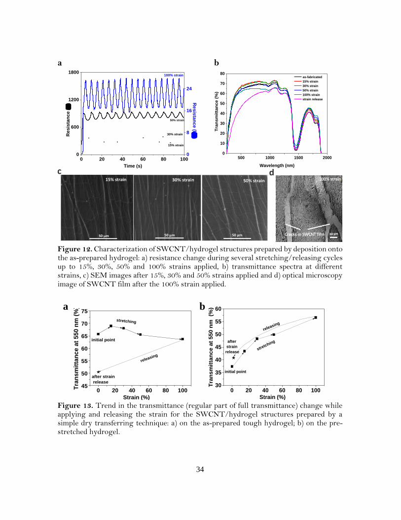
stretching-releasing cycles with 15, 30, 50% and 100% strains applied. Relative change in
the resistance of the SWCNT films between stretched and realeased states are about 40%,

33
80% and 300% for strains ε = 15%, 30% and 50%, respectively. When the highest value of
strain (ε = 100%) is applied the resistance reaches 28 kΩ (compared to the initial one of
200 Ω), which can be explained by the appearance of microcracks, visualized by an optical
microscope (Figure 12d). After the cracks appear in the SWCNT film, the resistance
remains in the range of 16-18 kΩ. However, we demonstrated stable behaviour of
fabricated SWCNT/hydrogelstructures, which was observed during 5000
stretching/releasing cycles while 30% strain is applied. Based on the performed
characterization it may be proposed that such SWCNT/hydrogelstructures can be used
for strain-sensitive applications. Transmittance spectra of the SWCNT/hydrogel
structures are presented in Figure 12b. The transmittance value at the wavelength of 550
nm decreases with the increase of the applied strain (Figure 13a). This can be explained
by the increase of the scattering in the hydrogel structure while stretching (Figure 14).
The scanning electron microscopy (SEM) images of the SWCNT networks after 15%,
30% and 50% strains applied are shown in Figure 12c. SEM studies of the
SWCNT/hydrogel structures confirmed slightly changed morphology of SWCNTs after
application of these strain values.
34
a b
0 20 40 60 80 1000
600
1200
1800100% strain
50% strain
30% strain
15% strain
Resis
tan
ce (k
)
0
8
16
24
Time (s)
Resis
tan
ce (
)
500 1000 1500 20000
10
20
30
40
50
60
70
80
Tra
ns
mit
tan
ce
(%
)
Wavelength (nm)
as-fabricated
15% strain
30% strain
50% strain
100% strain
strain release
Figure 12. Characterization of SWCNT/hydrogel structures prepared by deposition onto the as-prepared hydrogel: a) resistance change during several stretching/releasing cycles up to 15%, 30%, 50% and 100% strains applied, b) transmittance spectra at different strains, c) SEM images after 15%, 30% and 50% strains applied and d) optical microscopy image of SWCNT film after the 100% strain applied.
0 20 40 60 80 10045
50
55
60
65
70
75
releasing
stretching
initial point
Tra
nsm
itta
nce a
t 550 n
m (
%)
Strain (%)
after strain
release
0 20 40 60 80 100
30
35
40
45
50
55
60
releasing
initial point
stre
tching
Tra
ns
mit
tan
ce
at
55
0 n
m
(%)
Strain (%)
after
strain
release
Figure 13. Trend in the transmittance (regular part of full transmittance) change while applying and releasing the strain for the SWCNT/hydrogel structures prepared by a simple dry transferring technique: a) on the as-prepared tough hydrogel; b) on the pre-stretched hydrogel.
a b

35
Figure 14. Optical properties of the tough hydrogel: a) transmittance spectra of hydrogel at different stretched states during the first strain and after release; b) trend in the regular transmittance value for the tough hydrogel (at the wavelength of 550 nm); c) scattering spectra (diffusive part of full transmittance) of hydrogel at different stretched states during the first strain and after release.
3.2.3 Characterization of SWCNT/hydrogel structures obtained on the pre-stretched hydrogel
The same characterization is conducted for the second approach with the
SWCNT/hydrogel structures on hydrogel pre-stretched to ε = 30%. It is confirmed that
the procedure of the hydrogel substrate pre-stretching before the SWCNT film deposition
allows us to exploit formed wrinkles for stable and highly-stretchable electronic
components. A relative change in the resistance of the SWCNT film between stretched
and released states is about 7% for 15% and 30% strains applied (Figure 15a). When the
strain is higher than the pre-stretching strain value, we observe a significant increase of
the resistance about 10 times at 𝜀 = 50% and 60 times at 𝜀 = 100% applied. However, the
resistance value at the 100% strain is still lower for the pre-stretching approach (R = 6
kΩ) than that for the as-prepared hydrogel approach (R = 30 kΩ). The transmittance
spectra of the SWCNT/hydrogel structures (Figure 15b) demonstrate an increase in the
transparency with the applied strain. This can be explained by the process of wrinkle
removal leading to the improvement of the overall transmittance (from the initial value of
37% to 57% while stretched to 𝜀 = 100%). Thus, the pre-stretching approach allows us to
improve the transmittance of the whole structure at the stretched state. Moreover, after
the strain release, the transmittance returns back to the value of 40% close to the initial
0 20 40 60 80 100
70
80
90
releasing
initial
point
stretching
Tra
nsm
itta
nc
e a
t 5
50 n
m (
%)
Strain (%)
after strain release
500 1000 1500 2000 25000
20
40
60
80
100
Tra
nsm
itta
nce (
%)
Wavelength (nm)
as-prepared
15% strain
30% strain
50% strain
100% strain
strain release
400 600 800 1000 1200 1400 16000
2
4
6
8
10
12
Scatt
eri
ng
(%
)
Wavelength (nm)
as-prepared hydrogel
stretched to 50%
stretched to 100%

36
one. Thus, the pre-stretching of the hydrogel before SWCNTs deposition makes possible
to overcome the low conductivity at high strains and ensure high transparency. SEM
images of the SWCNT/hydrogel structures before pre-stretching and after the strain
release are shown in Figure 15c-e. From these images we can observe an excellent
adhesion of the SWCNT films to the hydrogel surface before stretching and after the
strain release. It is worth noting that the demonstrated approach of the
SWCNT/hydrogel composite fabrication can be utilizied for applications, where stable
performance of the electrodes during stretching is needed without the alteration of the
electrical properties.
a b
0 20 40 60 80 100
150
200
250
300
Time (s)
0
5
50% strain
100% strain
15% strain
Resis
tan
ce (k
)Resis
tan
ce (
)
30% strain
500 1000 1500 2000
0
10
20
30
40
50
60
70T
ran
sm
itta
nc
e (
%)
Wavelength (nm)
as-fabricated
15% strain
30% strain
50% strain
100% strain
strain release
Figure 15. Characterization of SWCNT/hydrogel structures prepared by deposition onto the pre-stretched hydrogel (the pre-strain value is 30%): a) resistance change while 15%, 30%, 50% and 100% strains are applied, b) transmittance spectra at different strains. SEM images of SWCNT/hydrogel structure morphology: c) before release of the hydrogel pre-strain after SWCNT film deposition, d) after release of the hydrogel pre-strain, e) after 15 cycles of stretching to 30% strain.

37
The resistance (𝑅𝑙 ) of the SWCNT/hydrogel structures during stretching is
estimated by the Equation 2:
𝑅𝑙 =𝑙
𝜎𝑙 𝑡𝑙 𝑤𝑙, (2)
where 𝜎𝑙 is the electrical conductivity of the SWCNT/hydrogel structures at certain
strain; 𝑙, 𝑤𝑙 and 𝑡𝑙 are length, width and thickness of the sample, respectively, at certain
strain.
Here we use two assumptions: (i) electrical resistivity of the structure is constant
while stretching; (ii) relative change in the SWCNTs and hydrogel dimensions, such as
width and thickness, are the same and can be found as [39]:
𝑙 = 𝑙0(1 + 𝜀); 𝑤𝑙 = 𝑤0(1 + 𝜀)−𝜈; 𝑡𝑙 = 𝑡0(1 + 𝜀)−𝜈 , (3)
where 𝑙0, 𝑤0, 𝑡0 – are lengh, width and thickness of the structure before stretching; 𝜀 is
applied strain value; 𝜈 is the Poisson’s ratio (𝜈 = 0.4 for tough hydrogel).
Using Equation 3 and two assumptions, we can express 𝑅𝑙 in terms of the
stretching:
𝑅𝑙 = 𝑅0(1 + 𝜀)1+2𝜈, (4)
where 𝑅0 is the electrical resistance of the SWCNT/hydrogelstructures before stretching.
We use Equation 4 to compare the experimental results and theoretical prediction
for the SWCNT/hydrogel resistance change during stretching. The results (Figure 16)
reveal a good agreement of the theory with the pre-stretched approach, and thus stable
adhession of the SWCNTs to hydrogel, which can be explained by appearance and
removal of the SWCNTs wrinkles confirmed by the SEM images. However, disagreement
of the theory with the as-fabricated approach is demonstrated due to the structural
changes and cracks formation in the SWCNT film while stretching.

38
0 20 40 60 80 100
2
3
4
5
6
Re
sis
tan
ce
(k
)
Strain (%)
theory
experiment
Figure 16. Comparison between experimental results and theoretical prediction for the relative resistance change of the SWCNT/hydrogel structures fabricated by pre-stretched hydrogel approach.
3.2.4 Applications of SWCNT/hydrogel structures
To demonstrate potential applications of our novel material, we develop a
stretchable human motion detector based on the SWCNT transfer onto the as-fabricated
tough hydrogel and by attaching the SWCNT/hydrogel electrodes (by the hydrogel side)
to an arm or to a finger (Figures 17a and b). To avoid mechanical failure at the junction
between the stretchable SWCNT/hydrogel structures and rigid wires for signal
processing we use an adhesive medical patch, so that the hydrogel directly adhere to the
skin. After the fabrication, sensors are attached onto the target places (knuckles and finger
flexor). As a result, the skin and SWCNT/hydrogel sensor behave as a single cohesive
stretchable object and deformation of the skin can be directly monitored. To detect the
relative resistance change from a palm to a fist (relaxed state of the arm (A) and clenched
into a fist (B)) we fabricated a SWCNT/hydrogel strain sensor with a 30 × 5 mm2 sensing
area (Figure 17a). In order to control small motions, such as particular finger flexing, we
fabricate a SWCNT/hydrogel strain sensor with a 10 × 5 mm2 sensing area (Figure 17b).
Thus, various types of skin strains could be monitored by the upward and downward
trends of the relative resistance data plots. One of the most promising advantages of such
devices is the option for repeatable and constant use of the sensor, which does not restrict
motions. Moreover, simple encapsulation of the SWCNT films in hydrogel will allow to
use such sensors in various implantable devices.

39
Figure 17. Application of SWCNT/hydrogel structures as active components: a) biocompatible strain-sensors for a human motion detection: resistance change of the SWCNT/hydrogel structure attached to a human arm under repeatable bending cycles, b) resistance change of a SWCNT/hydrogel electrode attached to a human finder depending on the bending angle.
Based on the second pre-stretching approach we fabricated SWCNT/hydrogel
based passive electrodes. Figure 18a illustrates a rigid LED-based electronic circuit, which
can be mechanically deformed. Previously it has been achieved by a wire connection of
LED arrays [40-42], which is rigid and has complicated technology to allow the
stretchabilty. Our approach is a novel way of electrical circuit creation, which allows to
fabricate biocompatible, transparent, and robust electrodes, stable under large
deformations and applicable for different wearable electronic devices. Validation of the
performance of the SWCNT/hydrogel structures in an electrical circuit is confirmed by a
constant intensity of a LED light under the applied strain. Practically, SWCNT film
patterns of any size and shape can be used for different wearable and skin-like devices
(Figure 18b). As one more example, we fabricate stable electrode for continuous
monitoring of electrocardiography (ECG) signals and its long-term variability, which has
improved signal-to-noise ratio (35 dB) compared to commonly used ECG electrodes (30
dB) (Figure 18c). The fact that hydrogels are intrinsically wet will allow them to remain
breathable and robust skin contact, revealing its safety for biomedical applications.

40
Figure 18. Application of SWCNT/hydrogel structures as passive electrodes: a) stretchable LED-based circuit with conductive SWCNT contacts at different stretched and twisted states, b) SWCNT/hydrogel-based patterned circuits at a relaxed state and stretched to 50 %; c) biocompatible electrodes for ECG signal measurements with photographs of SWCNT/hydrogel electrodes.
However, active and passive element, based on stretchable structures
SWCNTs/elastic substrate (demonstrated in Chapters 3.1 and 3.2) required energy
storage devices such as supercapacitors, which would be stretchable and transparent as
well.
3.3 Stretchable and transparent supercapacitors based on SWCNT films
Transparent energy conversion and storage devices have recently attracted
increasing attention due to their great potential as integrated power sources for displays
and windows in buildings, automobiles and aerospace vehicles [43-45]. On the other

41
hand, mechanical stretchability coupled with optical transparency of the energy storage
devices is required for many other applications, ranging from self-powered rolled-up
displays to self-powered wearable optoelectronics. The design of highly stretchable
devices is an essential element in the development of many unprecedented applications
such as electronic skin [46, 47] and smart energy storage clothes [48-50]. Portable and
wearable supercapacitors, coupled with either self-healability or stretchability [51, 52],
have particularly become a mainstream in the personalized electronics [53, 54]. However,
the development of both transparent and stretchable supercapacitors (TSSs) is still a
challenge, because typical existing electrodes are neither stretchable nor transparent (e.g.,
metal oxide on carbon-based electrodes), even though they might possess either
stretchability with low transmittance (e.g., conducting polymers) or transparency with
poor mechanical properties (e.g., ITO and other metal oxides). To our best knowledge, no
optoelectronic nor energy-related devices have been reported to show both good
transparency and high stretchability, though many devices with only one function have
been reported elsewhere e.g. [55-57].
Here, we applied dry deposited thin films of aerosol CVD synthesized SWCNT as
the electrodes to fabricate TSSs. Remarkably high specific capacitance and stability are
reached with the SWCNT electrodes in test cells and they are used to construct various
TSS prototypes. Such devices have attracted much attention from researchers and show
promising application potential in the field of wearable energy storage.
3.3.1 TSS based on liquid H2SO4/separator
Figure 19 schematically shows the procedure for preparing transparent and
stretchable supercapacitors with liquid H2SO4/separator. The pristine SWCNTs were
first deposited onto a preformed PDMS substrate (Fig. 19a) and then heated to 200oC in
order to anneal the surface and to desorb oxygen and organic impurities. After that 2
mol/dm3 H2SO4 solution was dropped on top of one of the SWCNT films and covered
with a paper separator (Fig. 19b). Finally, we constructed the supercapacitors by
assembling another PDMS-supported SWCNT electrode on top of the newly formed
separator/liquid H2SO4/SWCNT/PDMS multilayer film and glued this structure with

42
liquid PDMS at the edges. The fabricated supercapacitor is flexible as it can be seen from
Fig. 19d and can be stretched at least up to 50% strain, as will be demonstrated further.
Figure 19. Scheme of TSS fabrication process: (a) deposition of CNT1 and CNT2 films on PDMS, (b) Assembling the TSS by adding the separator and acid electrolyte, (c) Gluing two substrates with the liquid PDMS, (d) Photograph of the SWCNT based TSS with H2SO4 electrolyte and a nontransparent separator.
Immediately after the liquid PDMS glue was solidified, cyclic voltammogram
characteristics were measured at different scan rates from 10 to 500 mV/s (Figure 20).
The current increased with the increasing scan rate, as is characteristic for adsorption-
controlled reactions, implying that no mass transfer or kinetic limitations can be observed
and all the SWCNT surface sites are readily accessible even with the higher scan rates.
Thus, the same capacitance is achieved in the studied scan rate range. Due to the fact that
we used water based electrolyte and SWCNTs exhibit hydrophobic behavior, cyclic
voltammograms measured at different periods of time (Fig. 20a) showed the time
dependence. To follow the wetting behavior of the electrodes, the voltammograms were
measured immediately after the fabrication process, after 1, 4 and 12 hours. It can be easily
seen that after letting the device be impregnated in electrolyte for 12 hours the current
increased 6 times.
d

43
Figure 20. Electrochemical characterization of the SWCNT stretchable supercapacitors
with acid H2SO4: (а) Cyclic voltammograms at various scan rates (numbers indicates scan rates in mV s-1), (b) Constant current charging and discharging at 0.25A g-1.
To analyze the stretchability of the transparent supercapacitors, cyclic
voltammetric measurements were performed under mechanical deformations, such as
stretching after the fabrication process (Fig. 21b). It was observed that the capacitance of
the TSS was improved by stretching up to 50% strain. This can be explained by the fact
that stretching process led to better wetting of the SWCNTs by the electrolyte, thus
increasing the area available for the ion absorption. This type of TSSs has demonstrated
the capacitance Csp of 3.2 F g-1, which can be a basis for the comparison with the results
obtained for the improved structures.
Figure 21. (a) Cyclic voltammorgams of TSS with liquid acidic electrolyte at different periods of time after the fabrication, (b) Cyclic voltammorgams of TSS before stretching and being stretched at 50%.
b
a
b a

44
One of the main issues impeded the fabrication of highly stretchable
supercapacitors with high performance is the leakage of the electrolyte while applying
force to the supercapacitor. This problem is arisen from the configuration of the
stretchable supercapacitor device wherein liquid electrolyte is sandwiched by two
electrodes. Our further experiments were devoted to improvement of TSS configuration
by replacing the liquid electrolyte, which might suffer from leakage of a harmful liquid,
and consequently the non-transparent separator with a conformable gel electrolyte.
3.3.2 TSS based on a PVA-H2SO4 gel electrolyte
In order to improve the TSS performance we utilized another type of an
electrolyte, polyvinyl alcohol-H2SO4 gel. The first two fabrication steps were similar to
the ones described in the previously reported section. The last step is deposition of gel
viscous solution and pressing one of the electrolyte-coated electrodes on the other
electrode. Finally, after the solidification of the gel, the TSS contacting pads were
connected to the potentiostat-galvanostat for characterization of the device performance
(Figure 22). The whole device can be stretched at least up to 70% strain without any
obvious performance change, as it can be seen from Figure 22b. Additional advantages of
this supercapacitor is its high transparency – 75% (Figure 22e) and absence of harmful
liquid compounds, since the TSS is solid.

45
Figure 22. Properties of the TSSs based on gel electrolyte: (a) Schematic image of TSS fabrication process by deposition of gel electrolyte, (b) Electrochemical performance of as-fabricated TSS and under 10% and 70% strains, (c) CV curves for the first and hundredth stretching cycles, (d) Photograph of the TSS, (e) Transmittance spectrum of the device.
The current values can be compared with the values obtained with the acid liquid
electrolyte, but the shape of this graph looks better, which indicates better operating
parameters of such TSSs. This can be attributed to excellent properties of the PVA-H2SO4
electrolyte, less overall resistance because of a thinner electrolyte layer and high tensile
strength after solidification, in comparison with TSS based on the liquid electrolyte. The
capacitance of the device, Csp, calculated according to Equation 5 achieves the value of 7.4
F g-1:
𝐶𝑠𝑝 =1
2𝑚𝑉𝜈∫ 𝐼(𝑉)𝑑𝑉.
𝑉+
𝑉− (5)
where m is the mass of the active material in both electrodes, V is the potential
window between the positive and negative electrodes, 𝜈 - is the scan rate.
Thus, the problems in fabrication of highly stretchable supercapacitors, leakage of
the electrolyte, was solved by using the gel electrolyte.
d
e
a b c
e

46
3.3.3 TSS based on a PVA-H2SO4 gel electrolyte and pre-stretching approach
For further improvement of TSS characteristics under applied strain we developed
pre-stretching approach (Figure 23a), which is based on spreading of gel electrolyte on
the SWCNT film under applied strain. We achieved TSS structure, which can be stretched
up to 120% of strain without the significant change of the capacitance even after 1000
stretching cycles (Figure 23b). This approach allowed using the effect of better electrolyte
diffusion and electron transport through the layers due to pre-straining of the electrodes
with deposited gel electrolyte. In Figure 23c, the cyclic voltammograms of the TSS before
and after 1000 cycles between -0.8 and 0.8 V are shown and surprisingly, a small
improvement in current is seen. This is most likely again due to better electrolyte diffusion
over time and indicates excellent stability for the SWCNT electrodes and TSS device.
For this pre-stretching approach, the calculated specific capacitance value of Csp is
17.5 F g-1, which is higher than that obtained for the liquid or gel electrolyte without pre-
stretching. It ought to be remarked that recently we have fabricated transparent and
flexible electrochemical double-layer capacitor (EDLC) prototype from our SWCNT
films. The supercapacitor showed extremely high mass specific capacitance of 178 F g-1
compared to other carbon-based flexible and transparent EDLCs. However, that
supercapacitor had higher values of the capacitance due to the fact that material properties
were tested in a test cell, and the lateral conductivity of the SWCNT film was not an issue.
Therefore, the TSS fabricated here demonstrated relatively high capacitance in a
prototype cell being stretchable and transparent.
Figure 23. (a) Scheme of gel electrolyte deposition on pre-stretched SWCNTs on PDMS. (b) Cyclic voltammogramms of TSS made of pre-stretched electrodes at zero applied
a b c

47
strain, 40% strain, at first cycle of stretching to 120% and after 1000 cycle of stretching to 120% (scan rate – 200 mV/s), (c) Cyclic voltammogram of the supercapacitor before and after 1000 cycles between -0.8 and 0.8 V.
Thus, we optimized and eventually fabricated highly stretchable TSS by
combining our SWCNT films pre-strained on the PDMS substrate and using of a gel
electrolyte. The capacitance of these pre-strained TSSs remained nearly unchanged, even
under the strain up to 120%. This configuration enabled stretching of the supercapacitor
as an integrated unit and overcame the limitation of conventional stretchable
supercapacitor configuration wherein two electrodes move relative to the separator under
strain. The performance of the stretchable supercapacitors remained nearly unchanged
under 120% strain even under stretched conditions and after 1000 stretching cycles.
Superior stretchability combined with transparency and high specific capacitance
confirmed that fabricated supercapacitor has a great potential for broad practical
applications utilizing proposed materials and components. Additionally, such device in a
flexible or stretchable form could be further integrated in self-powered consumer
electronic system.
3.4 Flexible self-powered piezo-supercapacitor system for wearable
electronics
Energy harvesting is essential to achieve independent and sustainable electronic
devices, needed in self-powered systems, where no batteries are required, for
environmental monitoring and sensing or for biomedical devices in wearable electronic
applications [58-61]. Taking forms of irregular air flow/vibration, ultrasonic waves, body
movement, and hydraulic pressure, mechanical energy is ubiquitously available in our
living environment [62]. For the past decades, energy harvesting from the environment
has created a huge impact on the energy sector and thus the scientific community.
Therefore, devices, which convert low-frequency vibration and environmental activities
(e.g., wind, sound, friction, motion, and thermal energy) into electrical energy through
piezoelectric, triboelectric or pyroelectric effects have been implemented [63]. The

48
harvested energy is sufficient for the operation of small electronic devices in an aperiodic
manner using energy storage devices. However, real time generators are required to have
effective electrical output and longer cycle stability to support continuous operation in
environmental monitoring, defense, and implantable biomedical device applications.
Moreover, if such systems are realized in an advanced form, such as flexible, transparent
and lightweight, they will immediately become solutions for wearable consumer
electronics, serving as both energy harvesters and charging components. Many research
groups have attempted to fabricate high performance energy harvesters using different
materials and form-factors (e.g., films, fibers, and composites) [59-69].
Piezoelectric materials can convert ubiquitously irregular and low frequency
mechanical vibration into electricity and have been extensively studied for the use of
energy generators. Piezoelectric fluoropolymers, such as polyvinylidene fluoride (PVDF)
and its copolymer poly(vinylidene-trifluoroethylene) (P(VDF-TrFE)), on the other hand,
are lightweight, spinnable, soft, and flexible, making them excellent potential candidates
for the functional wearable electronics applications [70-72].
Here, we propose to combine and to utilize energy harvesting and storage
devices in a flexible manner, with the connection of piezo-harvester and energy
storage device as two separate portable and easily dismountable units, without the
use of any complicated liquid processes of the system fabrication. Our system
consists of solid-state supercapacitor based on single-walled carbon nanotube
(SWCNTs) films electrodes and P(VDF-TrFE) metalized film as energy harvester.
3.4.1 Fabrication and characterization of flexible supercapacitor
Figure 24a shows the schematic process flow of the fabrication of the flexible
piezo-supercapacitor. Figure 24b shows cross-sectional optical image of the
supercapacitor structure, which shows that SWCNTs are fully immersed into the
PVA/H2SO4 electrolyte, glued between two PET substrates. The whole thickness
of the flexible supercapacitor is around 250 μm. Figure 24c is a photograph of the
planar flexible supercapacitor in the relaxed state, where the transparency of the
device can be observed, and in flexed state (Figure 24d).

49
Figure 24. Characterization of the flexible gel-based supercapacitor: (a) Schematic illustration of the flexible supercapacitor fabrication: SWCNT film/PET electrodes are coated with PVA/H2SO4 electrolyte and assembled together; (b) cross section of the supercapacitor, which consist of symmetric SWCNT film/PET electrodes and PVA/H2SO4 electrolyte. Photographs of the flexible and transparent supercapacitor in relaxed (c) and flexed states (d).
After viscous PVA/H2SO4 gel deposited on two SWCNT film/PET
electrodes was solidified, CVs characteristics were measured by the potentiostatic
procedures at different scan rates from 100 to 1000 mV s-1. Figure 25a shows a
typical charging process of the supercapacitor. The current increased with the
increasing scan rate, as it is characteristic for adsorption-controlled reactions,
implying that no mass transfer or kinetic limitations can be observed and all the
SWCNT surface sites are readily accessible even with the higher scan rates. Thus,
the same capacitance is achieved in the studied scan rate range. Figure 25b shows
the triangle shaped GCD curve of the flexible supercapacitor, which were
conducted at 0.25 A g-1 (3.25 mA m-2) current value, demonstrating the reversible
capacitive behavior.
The specific capacitance of flexible supercapacitor, based on PET/SWCNT
electrodes, was calculated to be around 50 F g-1.
a
b
c
d

50
0 0.80.4-0.4-0.8-0.3
-0.2
-0.1
0
0.3
0.1
0.2
Cu
rre
nt
(m)
Voltage (V)
100 mV/s
200 mV/s
500 mV/s
1000 mV/s
0 2 4 6 8 10 12 14
0.8
0.6
Vo
lta
ge
(V
)
Time (s)
0
0.4
1.0
0.2
0.25 A/g
Figure 25. Electrochemical performance of the supercapacitors device with PVA/H2SO4 gel electrolyte: (a) cyclic voltammetry scans of flexible prototype measured at scan rates of 100, 200, 500 and 1000 mV s-1. (b) Galvanostatic charge and discharge curve measured at current of 0.25A g-1 (3.25 mA m-2).
3.4.2 Assembly of the piezo-supercapacitor system and measurements of its self-charging
performance
The whole piezo-supercapacitor system was assembled in one unit through
the rectifying diode-bridge connection. Flexible supercapacitor was fixed on top of
the specially designed motorized setup for repeatable mechanical action and
connected to the metalized piezo-film, which was fixed inside of the motorized setup
frame. Two electrodes of the supercapacitor were connected to the source meter for
the measurements of charging processes, occurred during mechanical action of the
whole system.
Before charging the flexible supercapacitor, the initial voltage of the device
was discharged to zero. After that, the charging process was performed across the
piezo-electric P(VDF-TrFE) under external mechanical action by generated
voltage potential. The P(VDF-TrFE) film in our system serves as the piezoelectric
energy harvester, which can convert mechanical vibration into electricity [73].
This potential, generated by P(VDF-TrFE), can drive the ions in the electrolyte of
a b
c

51
the supercapacitor to migrate towards the interface within the symmetric SWCNTs
electrodes, establishing a pseudo-capacitance at the interface and storing the
electricity in the form of electrochemical energy.
To measure the potential difference obtained on piezo-generator coated with thin
metal layers the system was assembled as it is shown in Figure 26a. P(VDF-TrFE)
metalized film was used as piezoelectric generator to harvest energy when beat back and
forth by a “motorized hand” at a frequency of 2.5 Hz. Figure 26b and c are photographs
of the setup with the flexible and transparent supercapacitor connected through the diode-
bridge to the P(VDF-TrFE) film, fixed in the frame. Red arrows in Figure 26b, c shows
the direction of the “motorized hand” movement: when the deflection angle reaches 30°,
frame goes back to the horizontal position while striking the table. Figure 26d shows
the output voltage profiles of the P(VDF-TrFE) film with two opposite polarity
peaks under a periodic mechanical action. The positive peak corresponds to the
stage under compressive force, while the negative peak represents the natural
relaxation process. The similar duration of the two stages gives rise to the
symmetric characteristics of the amplitude in the two peaks, which dictates the need
in charging of the supercapacitor with a rectification unit. Storing the generated
energy and driving functional electronic devices require a regulated DC power supply
while piezoelectric harvesters generate time-varying voltages; therefore, the rectification
is essential. After integration of diode-bridge to the system, the open-circuit voltage
generated by the piezo film was measured again. Figure 26f demonstrates repeatable
voltage peaks up to 2 V with the same positive polarity, which enables domination of the
supercapacitor charging process. For the proper characterization of piezo harvester along
with open-circuit voltage short-circuit current is measured. It is observed that piezo-film
shows current output close to 300 nA, which is in a good agreement with the previously
reported values for such materials (Figure 26e).

52
0 1 2 3 4-3
-2
-1
0
1
2
3
Vo
lta
ge
(V
)
Time (s)
0 1 2 3 4-300
-200
-100
0
100
200
300
Cu
rre
nt
(nA
)
Time (s)
0
1
2
4321
Voltage (
V)
Time (s)
0
Figure 26. (a) Schematic image of the built piezo-supercapacitor system and (b)-(c) its photographs during the mechanical action testing by a “motorized hand”. (d) The open-circuit voltage of as-assembled P(VDF-TrFE) film before rectification and (e) its short-circuit current. (f) The open-circuit voltage of the piezo-film after the diode-bridge integration.
To confirm that the increased voltage of the supercapacitor is a result of the
piezoelectric generator, we measured the voltage response of the flexible prototype under
the same periodic force conditions. We calculated the average mechanical force applied to
the piezoelectric layer during the mechanical action to be about 12.2 N. This value can be
commonly obtained by a human hand and considered as a driving force for operation of
the device without the use of motorized setup. Figures 27a and b show a typical charging
process of the whole device, working as flexible piezo supercapacitor system. According
to measured voltage of the flexible supercapacitor, it increased up to 500 mV within 20 s
after several repeated beating processes. Based on the obtained values we have calculated
the energy density of our system to be 5.06 W h g-1 at a power density - 182.25 W g-1.
Moreover, in order to measure the maximum voltage, which can be generated for such
type of supercapacitors by piezo-film we measure it during continuous beating process for
100 seconds. As it is shown in Figure 27b the maximum voltage generated by fabricated
d e f
a b c

53
piezo-supercapacitor system reached about 650 mV with slight decrease to 600 mV by 100
second.
0 50 100 150 200 250 300 3500
100
200
300
400
500
600
self-discharging
process
Vo
lta
ge (
mV
)
Time (s)
mechanical
action
0 20 40 60 80 1000
100
200
300
400
500
600
700
pause
self-discharging
continious mechanical action
Vo
ltag
e (
mV
)Time (s)
start of the
mechanical
beating
Figure 27. Self-charging performance of piezo-supercapacitor system (a) after several beating cycles and (b) after continuous beating, demonstrating saturated state of the device.
P(VDF-TrFE) is widely investigated due to its excellent mechanical flexibility and
high piezoelectric constant. Due to this fact, such material as P(VDF-TrFE) has been
already used as a piezo-generator for self-charging power cells. However, voltage
response in these works reached up to 300 mV within 240 s [74], 100 mV for 40 s [75],
110 mV for 300 s [76], which is at least six times lower and five times slower than the
results, obtained in our work. However, for driving LEDs backlights or powering analog
circuits and other small electronic devices it requires low leakage currents and voltages
that are higher than the input supply voltage. We propose several strategies to overcome
these problems. In order to reduce the leakage current and increase the self-discharging
time of the supercapacitor, used in our system, one can reduce the capacitance losses by
choice of electrodes and therefore interface of the electrode/electrolyte. As SWCNTs are
ideal candidates for flexible device electrodes, they can be modified by various coatings in
order to form SWCNTs/oxide and SWCNTs/polymer composite films to enhance the
capacitance and stability of the device. Moreover, the increase of the input voltage can be
a b

54
achieved by integration of tandem device structure, which would consist of sandwiched
piezo-films and several supercapacitors connected in parallel; or by the use of step-up
DC/DC converter and improved power management design, as it was successfully
demonstrated by Niu et. Al [77].
Along with the improved design of the whole system, fast discharging and loses in
such supercapacitors could be reduced by the improvement of the supercapacitor
structure, contribute to lengthen the time of the discharging, which is essential for smooth
and longer operation.
3.5 All-nanotube stretchable supercapacitor with low equivalent series
resistance
Currently, research in the domain of flexible and stretchable supercapacitors is
focused on adjusting electrodes, as they affect the performance the most [78-80].
However, the separator materials for such applications are left relatively unexplored.
Besides being dielectric, porous and chemically inert, the separators for stretchable
supercapacitors need to withstand multiple bending and stretching without severe
structural damages. The materials that meet afore-mentioned requirements are polymers
and polymer-based electrolytes, i.e. polyurethane membranes and polyvinyl alcohol
(PVA)-based electrolytes [81, 82]. However, despite been inexpensive, non-toxic and
highly stretchable, polyurethane membranes made by electrospinning are thicker than any
other separator materials (0.2 mm). Other polymer separators (polypropylene,
polyethylene), which are normally used in liquid electrolyte systems, offer several
advantages, such as good chemical stability, simplicity of manufacturing and processing.
However, there are several drawbacks, which are still present and cannot be easily solved.
The polymer separators show poor wetting with aqueous electrolytes. Their thicknesses
are usually above 20 μm and the attempts to create thinner polymer films usually reveal
the problems with their mechanical strength, and as a result they are unable to ensure

55
reliable short circuit protection. As such separators are not appropriate for stretchable
supercapacitor applications, another type of polyvinyl alcohol based electrolytes has been
already investigated, which additionally play role of separators and gluing materials and
can be stretchable after solidification. The smallest thickness of PVA separator is reported
to be 150 μm [83], resulting in relatively high internal resistances. In contrast with
separator materials mentioned above, some nanomaterials show outstanding mechanical
properties being less than 1 μm thick [84, 85]. In particular, boron nitride nanotubes
(BNNTs) is a dielectric nanomaterial that shows high Young's modulus and tensile
strength [86]. Generally, the BNNT film is a catalyst-free, dielectric [87, 88], entangled
and porous material, chemically inert in strong acids and alkalis [89], composed of
incredibly strong individual BNNTs, and thus considered perfect materials for separator
applications. So far very few works have been published where the BNNTs utilised as the
separator [90, 91]. None of them was either flexible or stretchable. However, due to its
remarkable properties, BNNTs are believed to be able to fulfil the requirements of the
growing industry and to provide a reliable and stable separator for stretchable
supercapacitors.
Here, we applied thin films of SWCNTs as the electrodes and BNNTs as the
separator to fabricate all-nanotube stretchable supercapacitors. The SWCNTs and
BNNTs films were chosen to be used together due to several important qualities, such as
costs, availability and their ideal structures for the use as an electrode and a separator,
respectively. The lattice structures, which strengthen the material between walls of both
materials, make it possible to test and characterize the device under mechanical stretching.
We successfully solved the problem of separator thickness and resistance keeping elastic
properties of the device.
3.5.1 Two-electrode cell and electrochemical measurements
We characterized the electrochemical properties of the materials using test cell
(Hohsen Corp.) in two-electrode configuration. Figure 28 schematically shows the
assembly procedure of the two-electrode test cell. The SWCNT films (1x1 cm2) were
transferred by a simple dry-press technique to the top and bottom current collectors.

56
After this, BNNT dispersions were prepared according to procedure previously
described. 1 mg of BNNTs were sonicated in Elmasonic S30 (H) ultrasonic bath with 5 ml
of toluene for 15-30 minutes yielding fine dispersion that in less than a minute precipitated
and accumulated in the bottom of the vial. A few minutes later, 3 ml of toluene from the
upper part of the vial were substituted by 3 ml of DMF with the use of micropipette. The
resulting mixture was bath-sonicated for 1-2 minutes. Interestingly, the attempts to
disperse BNNTs directly with the DMF/toluene mixture were not successful and
produced unstable dispersion. The BNNT separator was deposited onto both SWCNT
film electrodes so that it covered the electrode entirely by using airbrush to spread the 5
ml BNNT/toluene-DMF dispersion at 207 kPa with simultaneous heating of the current
collectors at 80 °C. Then all the parts were thermally treated at 220 °С for 40 minutes.
The thermal treatment is a crucial step as it removes the hydrocarbon residues from the
SWCNT synthesis as well as toluene and DMF from the BNNT separator, and thus
increases the electrochemical stability of the device. Subsequently, few drops (less than 0.5
ml) of 1M H2SO4 liquid electrolyte were added on top of the BNNT separator, and both
the top and bottom parts are screwed together (Figure 28).
During the CV measurements, the as prepared cells were cycled at 200 mV s-1 for
50 times to stabilize the cell before the data was collected. Subsequently, the CV curves
were recorded from 200 to 1000 mV s-1 scan rates with 100 cycles for each scan rate. For
the scan rate of 200 mV s-1 the test cell was further tested for durability under 20 000 CV
cycles. GCD measurements were performed at different DC currents throughout the
entire potential range up to 25 A g-1. The EIS spectra of the two-electrode test cell have
been collected in a potentiostatic mode with the 5 mV amplitude in the frequency range
from 1 Hz to 500 kHz with 50 points in total.

57
Figure 28. Schematic two-electrode cell assembly process.
3.5.2 Fabrication of the all-nanotube SWCNT/BNNT stretchable supercapacitor
prototype
For the stretchable prototype PDMS substrates were prepared. The base and
curing agent were mixed with 10:1 ratio by mass, poured onto a laboratory glass, degassed
and cured at 90 °C for 40 minutes. After the curing, the sample was cut into rectangular
pieces of a desired size. The whole process of SSC assembly is schematically shown in
Figure 29. For the SSC prototype fabrication dimethylformamide (DMF) and toluene
were replaced by isopropanol (IPA) to prepare the dispersion of BNNTs. This can be
explained by the fact that the prototype cannot be heated to remove DMF and toluene
from the SWCNT electrode surface and toluene causes swelling of the PDMS substrate.
Similarly, BNNTs were sonicated in toluene. After the sonication, 3 cycles of
centrifugation in Sigma 3-30KS centrifuge at 6000 RPM for 5 minutes were performed
with the subsequent toluene supernatant removal after each step. This was followed by 3
cycles of washing the BNNTs with the equal volume of IPA and centrifugation under the
same parameters. The final BNNT/IPA mixture was bath sonicated for 30 minutes
yielding a fine dispersion.
After BNNT/IPA dispersion was prepared two electrodes were assembled as
follows. The SWCNT film (2x1 cm2) was deposited on top of the first PDMS substrate
and 0.5 ml BNNT separator drop-casted from the BNNT/IPA dispersion. The whole
structure was heated up to 220°C for 40 minutes. The second PDMS substrate was

58
covered with a thin layer of a PVA/H2SO4 gel-electrolyte and SWCNT films were
transferred on top of it. The need for PVA in the supercapacitor prototype is dictated by
the fact, that under stretching conditions practically any liquid leaks from the device. To
solve this problem, we utilized the solid-state electrolyte (PVA and H2SO4), proven to
withstand the mechanical stresses without the electrolyte leakage. It should be noted that
the PVA/H2SO4 gel rapidly decomposes when heated, and thus the thermal treatment of
the SWCNT films needs to be completed beforehand. After the solvent evaporation, two
semi-plates were attached facing each other and glued at the edges with PDMS and left
to dry overnight. Here, H2SO4 plays the role of the electrolyte and impregnates the
SWCNT electrodes, and the BNNTs act as a separator. Similar techniques, described
above for the two-electrode cell, were used for investigation of the electrochemical
performance of the fabricated stretchable supercapacitor (CV, GCD and EIS methods).
Figure 29. Process flow of stretchable supercapacitor fabrication.
3.5.3 Characterization of all-nanotube SWCNT/BNNT stretchable supercapacitor
The morphology of the BNNT separator on top of the SWCNT film was
characterized by SEM (Figure 30a). The BNNT layer forms a porous structure that is
beneficial to the SSC in terms of mass transport and ion permeability. In order to estimate
the thickness of the separator layer, BNNTs were deposited on the surface of the SWCNT
film transferred on an aluminum foil and the cross-section of the structure was cut by

59
means of SEM FIB. As can be seen from Figure 30b the thickness of the BNNT films
utilized for SSC fabrication was around 550 nm.
Figure 30. SEM images of the separator layer. (A) BNNT separator on top of the SWCNT film electrode on PDMS, (B) cross-section of the BNNT layer.
Almost rectangular shape of the CV curves (Figure 31a) indicates EDLC
capacitance of the cell being measured at 200, 400, 600, 800 and 1000 mV s-1 scan rates.
Perfect shape of the CVs can be attributed to good transport properties of the BNNT
separator. The calculated total capacitance of C = 105 μF and specific capacitance of the
cell was Csp = 82 F g-1 or 94 µF cm-2. Here, the areal capacitance (CA) was calculated using
SWCNT electrode mass (m) and area (A) of 1.5 x 1.5 cm2 – Equations (6) and (7):
𝐶 =𝐶𝑠𝑝𝑚
4, (6)
𝐶𝐴 =2𝐶
𝐴. (7)
The GCD curves, shown in Figure 31b, demonstrate symmetrical behavior and
reflect good performance at different DC currents up to 25 A/g throughout the entire
potential range. Additionally, the two-electrode setup was tested for durability under
20000 CV cycles. The specific capacitance retained 96% of its initial value. In order to
compare performance of the used materials a two-electrode cell supercapacitor with the
commercial separator (25 μm thick Celgard separator purchased from MTI Corporation)
was evaluated. As shown in Figure 31d, the Nyquist plots display at the high-frequency

60
region semi-circles of a similar size for both separators and these are attributed to charge
transfer processes on the electrode surfaces. Moreover, the straight lines observed in the
low-frequency region represent ion diffusion in the system and the more vertical line
suggest improved ion transfer trough the BNNT. The extracted equivalent series
resistance (ESR) of the supercapacitor assembled in a test cell with BNNT separator (ESR
= 4.6 Ω) is comparable to cell assembled with the commercial one (ESR value of 5.9 Ω).
Figure 31. Electrochemical performance of the two-electrode test cell. (A) CV curves at various scan rates. (B) Galvanostatic charge-discharge at high currents. (C) CV curves of 20 000 load cycles collected at a scan rate of 200 mV s-1. (D) Electrochemical impedance spectra of the BNNT separator (blue) and commercial separator (black).
After the material examination, we characterized the stretchable supercapacitor
(SSC) prototype in a two-electrode configuration. Figure 32a demonstrates cyclic
voltammograms of the fabricated SSC prototype according to the scheme presented
previously, at different scan rates. It is worth noting that for the stretchable prototype
lower currents and higher impedance obtained in comparison with the test cell. The
supercapacitor was stretched up to 25% and 50% strain values for 1000 cycles. CVs at
different scan rates and EIS spectra in different stretched positions were measured and
shown in Figure 32c and b, respectively. The fabricated SSC could withstand only one
stretching cycle with a 55% strain applied due to the limitation in the PDMS substrate

61
mechanical properties. For the as-fabricated stretchable prototype specific capacitance
reached (Csp) 7.7 F g-1 and total device capacitance of C = 20 μF. Increasing the strain to
50% we observed an increase in the current (Figure 32c). The value of specific capacitance
also increase up to 8.4 F g-1 due to better electrolyte diffusion while stretching. As it is
shown in Figure 32b, the lowest ESR value of 125 Ω was measured by means of EIS after
1000 cycles at 25% strain, which slightly increased to 200 Ω after the 50% strain. This
value is still lower than ESR = 250 Ω of the as-fabricated device. It is also noteworthy
that the changes in the low-frequency region line in the impedance spectra suggest
improved ion transfer with the stretching. Another important finding is that the ESR
value of the all-nanotube SSC prototype was two orders of magnitude lower compared to
the stretchable supercapacitors with PVA/H2SO4 separator of the similar stretchable
configuration (ESR = 15 kΩ). Such a high difference in the ESR yields in a hundred times
higher power density of the SSC with the BNNT separator. Additionally, the ESR and
capacitance values obtained for the SSC is lower than that of two-electrode test cell
supercapacitor, as the test cell electrodes are made of stainless steel, which affects the
charge transfer across thr electrodes. It is worth mentioning that for a stretchable
supercapacitor the value of the total device thickness (h) was around 1100 μm, including
the PDMS substrates, and less than 100 μm excluding it, with the electrode area of the
device is 2 x 1 cm2. Volumetric capacitance CVol of the device was calculated according to
the eqn (8):
𝐶𝑉𝑜𝑙 =𝐶
𝐴 ∙ℎ. (8)
Figure 32. Stretchable supercapacitor characteristics. (A) CVs at different scan rates, (B) EIS spectra of the as-fabricated supercapacitor (blue) after 100 stretching cycles under 25% (black) strain with inset showing ESR of PVA/H2SO4 used for stretchable

62
supercapacitor, 50% (red) elongation; (C) CVs of as-fabricated SSC device (blue), 25% (black) and 50% (red) strain after 1000 stretching cycles.
According to this formula the as-fabricated SSC exhibits the volumetric
capacitance of 0.4 mF cm-3. As it was mentioned, the SSC device was stretched up to 50%
strain without any significant change in the electrochemical performance. It can be seen
from Figure 32c, increasing the strain results in a small increase in the current and
consequently in the volumetric capacitance from 0.4 to 0.5 mF cm-3.
However, our SSC could withstand only one stretching cycle at 55%, which was
explained by appearance of micro cracks in the BNNT separator layer and leading to the
short circuit between the SWCNT electrodes. The size of cracks in the BNNT layer was
over 10 μm, which is critical for the device performance. Increase in values of volumetric
capacitance can be explained by the effect of better electrolyte diffusion and electron
transport through the layers due to stretching of the electrodes with the deposited gel
electrolyte, which was also discussed in our previous work. Table 3 summarises all
calculated values of the as-fabricated SSC device at 0% strain applied and after maximum
strain of 50% applied for 1000 stretching/releasing cycles. In order to provide full
characterization of the SSC, volumetric energy densities in both stretched and as
fabricated conditions were calculated using eqn (9):
𝑊 = 0.5 𝐶𝑠𝑝 𝑚 (∆𝑉)2
4∙3600∙𝑉𝑜𝑙, (9)
where Vol is the total volume of the device, including both electrodes, separator and
substrates volumes. Values of the volumetric capacitance and volumetric energy density
for supercapacitors assembled in the test cell were calculated and compared with
respective values recalculated for the SSC prototype (excluding the thickness of the
PDMS substrate) and are also presented in Table 2. As can be seen, the values of
volumetric capacitance for supercapacitors assembled in the two-electrode cell
configuration with the commercial separator and with BNNTs separator were calculated
to be 7.9 and 8.5 mF cm-3, respectively. For the SSC prototype at the initially relaxed state

63
this value reaches 0.9 mF cm-3 while after 1000 cycles of stretching to 50% strain and
almost no degradation was observed with slightly increased value of 1.0 mF cm-3.
Table 2. Parameters, calculated for all-nanotube supercapacitors: two-electrode cell assembly and stretchable prototype.
Type of the device assembly
Specific capacitance, Csp
(F g-1)
Areal capacitance, CA (µF cm-2)
Volumetric capacitance, CVol (mF cm-3)
Volumetric energy density, W
(mW h cm−3)
Volumetric power density, P
(mW cm−3)
Equivalent series resistance, ESR (Ω)
Two-electrode cell
Commercial separator
76 68 7.9 3.5 4800 5.9
BNNT separator
82 73 8.5 3.7 6200 4.6
Stretchable prototype with BNNT separator
As fabricated 7.7 19 0.9 0.09 32 250
After 1000 cycles of 50% strain
8.4 21 1.0 0.10 40 200
In addition to the volumetric energy density, power density P (W cm−3) of the
supercapacitor is also important for the practical applications and could be calculated
according to the following Equation 10:
P =∆V2
4 ESR∙Vol. (10)
The energy density of 3.7 mW h cm−3 at the power density of 6200 mW cm−3 were
obtained for the two-electrodes cell with the BNNTs separator, which is higher than the
energy density of 3.5 mW h cm−3 at the power density 4800 mW cm−3 for the test cell
with the commercial separator. The difference can be attributed to slightly lower ESR and
smaller thickness of the BNNTs separator. The volumetric energy density for the
fabricated and stretched to 50% strain prototype where 0.09 and 0.10 mWh cm−3,
respectively, with improved values of volumetric power density from 32 mW cm−3 to 40
mW cm−3 after the stretching. Such impressive difference in the volumetric energy and
power densities values can be explained by lower values of specific capacitances of SSC
64
and smaller operating voltage window. For further increase of energy density values, the
voltage range of the SWCNT electrodes in an aqueous electrolyte can be increased by
purifying the SWCNTs form Fe catalyst particles. On the other hand, alternative
electrolytes, such as organic solvents or ionic liquids with larger electrochemical window,
can be used to increase the energy density values. However, the values of volumetric
power densities obtained in this work can be compared with the reported in the literature
[92-94] for flexible and stretchable all-solid-state energy storage devices based on similar
classes of nanomaterials.

65
Conclusions
Recent developments in polymer science, thin-film processing, and
nanotechnology have demonstrated ultrathin and soft electronic devices which replicates
mechanical properties of the skin or can form intimate and robust contact with the skin
on polymeric supporting layers. So far, research has generated significant progress in
device capabilities, materials exploration, skin-integration techniques, powering systems,
and mechanical design, which have produced stretchable and flexible devices capable of
providing relevant information in a number of applications. Thus, it is extremely essential
to develop and integrate new materials, solutions and methods for novel immerging class
of stretchable and transparent electronics.
First of all, we report new transparent, stretchable, conductive and biocompatible
structures of elastic polymers (such as PDMS and hydrogels) modified by SWCNT films
to create passive electrodes and active sensors for wearable and skin-like electronics. We
introduce here a one-step, universal and applicable method for SWCNT/hydrogel and
SWCNT/PDMS structures fabrication, withstanding intrinsic stretching up to 100%
strain. Our method holds advantages, compared to those reported previously, as it is a
direct transfer from the filter onto a hydrogel surface without the need for a sacrificial
layer or any other intermediate steps. We apply our approach to create a new set of soft
and robust components, such as electrodes for ECG monitoring and active sensors for a
human motion detection.
In order to create energy storage devices, which could be further integrated with
such active sensors we successfully developed highly stretchable supercapacitors, based
on SWCNT films as current collectors and electrode material. All-solid TSS based on
PVA–H2SO4 gel electrolyte showed specific cell capacitance of 7.4 F g-1. In order to
increase durability to stretching of such TSS another technique was performed based on
pre-stretching of the electrodes with the deposited gel electrolyte. This approach allowed
using the effect of better electrolyte diffusion and electron transport through the electrode
layers and obtain the capacitance value of 17.5 F g-1, significantly higher than previously
reported. Furthermore, TSS based on pre-stretching approach demonstrated

66
stretchability up to 120% with excellent stability even after stretching for 1000 cycles in
addition to electrochemical stability after 1000 charging–discharging cycles.
Performance of such devices was improved by fabrication of high-performance,
stable, low equivalent series resistance, all-nanotube stretchable supercapacitor based on
SWCNT electrodes and BNNT separator. The fabrication process is very simple, fast and
based on dry transfer and airbrush techniques. The fabricated two-electrode test cell with
the materials mentioned above demonstrates excellent stability after 20 000
electrochemical charging/discharging cycles, and EDLC behaviour and retains 96% of its
initial capacitance of 82 F g−1. Remarkably, the BNNT separator of only 0.5 μm thickness
ensures reliable short circuit protection and low ESR of the SSC. These exciting findings
demonstrate that SCs fabricated with the method used in this research hold a great
promise for use as high-performance stretchable energy storage devices in the future.
Finally, we have successfully demonstrated the technology of flexible
piezoelectric-driven self-charging supercapacitor power cell fabrication, which is based on
P(VDF-TrFE) metalized piezo-film and and transparent supercapacitor with SWCNT
film/PET electrodes and PVA/H2SO4 electrolyte, which can be used to simultaneously
harvest and store the mechanical energy to electrochemical energy. A polarized P(VDF-
TrFE) metalized film was fixed in a special “motorized hand” and external mechanical
impact establishes a piezoelectric potential across this film, while the whole system
produces the mechanical action at a frequency of 2.5 Hz. Piezoelectric film serves as a
driving force for flexible supercapacitor charging and therefore storing the energy in the
form of electrochemical one. The supercapacitors exhibited the self-charging capability
under repeatable applied force and can be charged up to 500 mV in 20 s. At the same time,
the maximum voltage generated by fabricated piezo-supercapacitor system reached about
650 mV. The fabrication procedure is simple and could be easily scaled-up to large-scale
production. The piezo-supercapacitor system provides a new promising direction in the
supercapacitor research for the development of next generation self-powered sustainable
power sources for wearable and flexible electronic devices.

67
Bibliography [1] S. Harada, K. Kanao, Y. Yamamoto, T. Arie, S. Akita and K. Takei, ACS Nano, 2014, 8, 12851-12857.
[2] H.-H. Chou, A. Nguyen, A. Chortos, J. W. F. To, C. Lu, J. Mei, T. Kurosawa, W.-G. Bae, J. B. H. Tok
and Z. Bao, Nat. Commun., 2015, 6.
[3] B. Su, S. Gong, Z. Ma, L. W. Yap and W. Cheng, Small, 2015, 11, 1886-1891.
[4] Y. Hattori, L. Falgout, W. Lee, S.-Y. Jung, E. Poon, J. W. Lee, I. Na, A. Geisler, D. Sadhwani, Y. Zhang,
Y. Su, X. Wang, Z. Liu, J. Xia, H. Cheng, R. C. Webb, A. P. Bonifas, P. Won, J.-W. Jeong, K.-I. Jang, Y. M.
Song, B. Nardone, M. Nodzenski, J. A. Fan, Y. Huang, D. P. West, A. S. Paller, M. Alam, W.-H. Yeo and J.
A. Rogers, Adv. Healthcare Mater., 2014, 3, 1597-1607.
[5] W.-H. Yeo, Y.-S. Kim, J. Lee, A. Ameen, L. Shi, M. Li, S. Wang, R. Ma, S. H. Jin, Z. Kang, Y. Huang
and J. A. Rogers, Adv. Mater., 2013, 25, 2773-2778.
[6] D.-H. Kim, N. Lu, R. Ma, Y.-S. Kim, R.-H. Kim, S. Wang, J. Wu, S. M. Won, H. Tao, A. Islam, K. J. Yu,
T.-i. Kim, R. Chowdhury, M. Ying, L. Xu, M. Li, H.-J. Chung, H. Keum, M. McCormick, P. Liu, Y.-W.
Zhang, F. G. Omenetto, Y. Huang, T. Coleman and J. A. Rogers, Science, 2011, 333, 838-843.
[7] C. S. Haines, M. D. Lima, N. Li, G. M. Spinks, J. Foroughi, J. D. W. Madden, S. H. Kim, S. Fang, M.
Jung de Andrade, F. Göktepe, Ö. Göktepe, S. M. Mirvakili, S. Naficy, X. Lepró, J. Oh, M. E. Kozlov, S. J.
Kim, X. Xu, B. J. Swedlove, G. G. Wallace and R. H. Baughman, Science, 2014, 343, 868-872.
[8] C.-H. Li, C. Wang, C. Keplinger, J.-L. Zuo, L. Jin, Y. Sun, P. Zheng, Y. Cao, F. Lissel, C. Linder, X.-Z.
You and Z. Bao, Nat. Chem., 2016, 8, 618-624.
[9] M.-S. Lee, K. Lee, S.-Y. Kim, H. Lee, J. Park, K.-H. Choi, H.-K. Kim, D.-G. Kim, D.-Y. Lee, S. Nam and
J.-U. Park, Nano Lett., 2013, 13, 2814-2821.
[10] S. Harada, W. Honda, T. Arie, S. Akita and K. Takei, ACS Nano, 2014, 8, 3921-3927.
[11] B. K. Sharma, B. Jang, J. E. Lee, S.-H. Bae, T. W. Kim, H.-J. Lee, J.-H. Kim and J.-H. Ahn, Adv. Funct.
Mater., 2013, 23, 2024-2032.
[12] Kaltenbrunner, M.; Sekitani, T.; Reeder, J.; Yokota, T.; Kuribara, K.; Tokuhara, T.; Drack, M.;
Schwodiauer, R.; Graz, I.; Bauer-Gogonea, S.; Bauer, S.; Someya, T. An Ultra-Lightweight Design for
Imperceptible Plastic Electronics. Nature 2013, 499, 458−463.
[13] Yuhao Liu, Matt Pharr, and Giovanni Antonio Salvatore, Lab-on-Skin: A Review of Flexible and
Stretchable Electronics for Wearable Health Monitoring, ACS Nano 2017, 11, 9614-9635.
[14] K. Park, D.-K. Lee, B.-S. Kim, H. Jeon, N.-E. Lee, D. Whang, H.-J. Lee, Y. J. Kim and J.-H. Ahn, Adv.
Funct. Mater., 2010, 20, 3577-3582.
[15] S. H. Chae, W. J. Yu, J. J. Bae, D. L. Duong, D. Perello, H. Y. Jeong, Q. H. Ta, T. H. Ly, Q. A. Vu, M.
Yun, X. Duan and Y. H. Lee, Nat. Mater., 2013, 12, 403-409.
[16] T. Q. Trung and N.-E. Lee, Adv. Mater., 2016, DOI: 10.1002/adma.201603167.
[17] N. Lee and T. Q. Tran, J. Mater. Chem. C, 2017, DOI: 10.1039/C6TC05346G.

68
[18] Anisimov, A.S., Nasibulin, A.G., Jiang, H., Launois, P., Cambedouzou, J., Shandakov, S.D., Kauppinen,
E.I. 2010. Mechanistic investigations of single-walled carbon nanotube synthesis by ferrocene vapor
decomposition in carbon monoxide. Carbon, 48, 380-388.
[19] Nasibulin, A.G., Moisala, A., Brown, D.P., Jiang, H., & Kauppinen, E.I. 2005. A Novel Aerosol Method
for Single Walled Carbon Nanotube Synthesis. Chem. Phys. Lett., 402, 227-232.
[20] Moisala, A., Nasibulin, A.G., Brown, D.P., Jiang, H., Khriachtchev, L., & Kauppinen, E.I. 2006. Single-
walled Carbon Nanotube Synthesis Using Ferrocene and Iron Pentacarbonyl in a Laminar Flow Reactor.
Chem. Eng. Sci., 61, 4393-4402.
[21] Nasibulin, A.G., Queipo, P., Shandakov, S.D., Brown, D.P., Jiang, H., Pikhitsa, P.V., Tolochko, O.V.,
& Kauppinen, E.I. 2006. Studies on mechanism of single-walled carbon nanotube formation. J. Nanosci.
Nanotech., 6, 1233-1246.
[22] Lee, K. Y.; Mooney, D. J. Hydrogels for Tissue Engineering. Chemical Reviews. 2011, 101, 1869–1879.
[23] Aregueta-Robles, U. A.; Woolley, A. J.; Poole-Warren, L. A.; Lovell, N. H.; Green, R. A. Organic
Electrode Coatings for next-Generation Neural Interfaces. Front. Neuroeng. 2014, 7.
[24] Imaninezhad, M.; Kuljanishvili, I.; Zustiak, S. P. A Two-Step Method for Transferring Single-Walled
Carbon Nanotubes onto a Hydrogel Substrate. Macromol. Biosci. 2017, 17 (3).
[25] Peppas, N. A.; Hilt, J. Z.; Khademhosseini, A.; Langer, R. Hydrogels in Biology and Medicine: From
Molecular Principles to Bionanotechnology. Advanced Materials. 2006, 18, 1345–1360.
[26] Jeong, J. W.; McCall, J. G.; Shin, G.; Zhang, Y.; Al-Hasani, R.; Kim, M.; Li, S.; Sim, J. Y.; Jang, K. I.;
Shi, Y.; et al. Wireless Optofluidic Systems for Programmable In Vivo Pharmacology and Optogenetics. Cell
2015, 162 (3), 662–674.
[27] Lin, S.; Yuk, H.; Zhang, T.; Parada, G. A.; Koo, H.; Yu, C.; Zhao, X. Stretchable Hydrogel Electronics
and Devices. Adv. Mater. 2016, 28 (22), 4497–4505.
[28] Liu, X.; Yuk, H.; Lin, S.; Parada, G. A.; Tang, T. C.; Tham, E.; de la Fuente-Nunez, C.; Lu, T. K.; Zhao,
X. 3D Printing of Living Responsive Materials and Devices. Adv. Mater. 2018, 30 (4).
[29] Yuk, H.; Zhang, T.; Parada, G. A.; Liu, X.; Zhao, X. Skin-Inspired Hydrogel-Elastomer Hybrids with
Robust Interfaces and Functional Microstructures. Nat. Commun. 2016, 7.
[30] Rogers, J. A.; Someya, T.; Huang, Y. Materials and Mechanics for Stretchable Electronics. Science.
2010, 1603–1607.
[31] Morin, S. A.; Shepherd, R. F.; Kwok, S. W.; Stokes, A. A.; Nemiroski, A.; Whitesides, G. M. Camouflage
and Display for Soft Machines. Science. 2012, 337 (6096), 828–832.
[32] Pan, L.; Yu, G.; Zhai, D.; Lee, H. R.; Zhao, W.; Liu, N.; Wang, H.; Tee, B. C.-K.; Shi, Y.; Cui, Y.; et al.
Hierarchical Nanostructured Conducting Polymer Hydrogel with High Electrochemical Activity. Proc. Natl.
Acad. Sci. 2012, 109 (24), 9287–9292.

69
[33] Yu, C.; Duan, Z.; Yuan, P.; Li, Y.; Su, Y.; Zhang, X.; Pan, Y.; Dai, L. L.; Nuzzo, R. G.; Huang, Y.; et al.
Electronically Programmable, Reversible Shape Change in Two- and Three-Dimensional Hydrogel
Structures. Adv. Mater. 2013, 25 (11), 1541–1546.
[34] Guiseppi-Elie, A. Electroconductive Hydrogels: Synthesis, Characterization and Biomedical
Applications. Biomaterials. 2010, 31, 2701–2716.
[35] Shi, Z.; Gao, X.; Ullah, M. W.; Li, S.; Wang, Q.; Yang, G. Electroconductive Natural Polymer-Based
Hydrogels. Biomaterials. 2016, 111, 40–54.
[36] Mawad, D.; Lauto, A.; Wallace, G. G. Conductive Polymer Hydrogels. In Polymeric Hydrogels as Smart
Biomaterials; 2016, 19–45.
[37] Ahn, Y.; Lee, H.; Lee, D.; Lee, Y. Highly Conductive and Flexible Silver Nanowire-Based
Microelectrodes on Biocompatible Hydrogel. ACS Appl. Mater. Interfaces 2014, 6 (21), 18401–18407.
[38] Sandu, G.; Ernould, B.; Rolland, J.; Cheminet, N.; Brassinne, J.; Das, P. R.; Filinchuk, Y.; Cheng, L.;
Komsiyska, L.; Dubois, P.; et al. Mechanochemical Synthesis of PEDOT:PSS Hydrogels for Aqueous
Formulation of Li-Ion Battery Electrodes. ACS Appl. Mater. Interfaces 2017, 9 (40), 34865–34874.
[39] Lipomi, D. J.; Vosgueritchian, M.; Tee, B. C. K.; Hellstrom, S. L.; Lee, J. A.; Fox, C. H.; Bao, Z. Skin-
like Pressure and Strain Sensors Based on Transparent Elastic Films of Carbon Nanotubes. Nat. Nanotechnol.
2011, 6 (12), 788–792.
[40] Feng, C.; Jiang, L. Y. Investigation of Uniaxial Stretching Effects on the Electrical Conductivity of
CNT-Polymer Nanocomposites. J. Phys. D. Appl. Phys. 2014, 47 (40).
[41] Yamada, T.; Hayamizu, Y.; Yamamoto, Y.; Yomogida, Y.; Izadi-Najafabadi, A.; Futaba, D. N.; Hata, K.
A Stretchable Carbon Nanotube Strain Sensor for Human-Motion Detection. Nat. Nanotechnol. 2011, 6 (5),
296–301.
[42] Yuk, H.; Zhang, T.; Parada, G. A.; Liu, X.; Zhao, X. Skin-Inspired Hydrogel-Elastomer Hybrids with
Robust Interfaces and Functional Microstructures. Nat. Commun. 2016, 7.
[43] J. S. Huang, G. Li and Y. Yang, A semi-transparent plastic solar cell fabricated by a lamination process,
Adv. Mater., 2008, 20, 415–419.
[44] C.-C. Chen, et al., Visibly transparent polymer solar cells produced by solution processing, ACS Nano,
2012, 6, 7185–7190.
[45] H. Y. Jung, M. B. Karimi, M. G. Hahm, P. M. Ajayan and Y. J. Jung, Transparent, Flexible
supercapacitors from nanoengineered carbon films, Sci. Rep., 2012, 2, 773–777.
[46] K. Takei, T. Takahashi, J. C. Ho, H. Ko, A. G. Gillies, P. W. Leu, R. S. Fearing and A. Javey, Carbon
nanotube active-matrix backplanes for conformal electronics and sensors, Nat. Mater., 2010, 9, 821–826.
[47] S. C. B. Mannsfeld, B. C. K. Tee, R. M. Stoltenberg, C. V. H. H. Chen, S. Barman, B. V. O. Muir, A. N.
Sokolov, C. Reese and Z. N. Bao, Highly sensitive flexible pressure sensors with microstructured rubber
dielectric layers, Nat. Mater., 2010, 9, 859–864.

70
[48] D.-H. Kim, N. Lu, R. Ma, Y.-S. Kim, R.-H. Kim, S. Wang, J. Wu, S. M. Won, H. Tao, A. Islam, K. J.
Yu, T.-i. Kim, R. Chowdhury, M. Ying, L. Xu, M. Li, H.-J. Chung, H. Keum, M. McCormick, P. Liu, Y.-W.
Zhang, F. G. Omenetto, Y. Huang, T. Coleman and J. A. Rogers, Epidermal Electronics, Science, 2011, 333,
838–843.
[49] L. Hu, M. Pasta, F. L. Mantia, L. Cui, S. Jeong, H. D. Deshazer, J. W. Choi, S. M. Han and Y. Cui,
Aqueous Supercapacitors on Conductive Cotton, Nano Lett., 2010, 10, 708–714.
[50] B. Yue, C. Wang, X. Ding and G. G. Wallace, Polypyrrole coated nylon lycra fabric as stretchable
electrode for supercapacitor applications, Electrochim. Acta, 2012, 68, 18–24.
[51] C. Yu, C. Masarapu, J. Rong, B. Wei and H. Jiang, Stretchable Supercapacitors Based on Buckled
Single-Walled Carbon-Nanotube Macro films, Adv. Mater., 2009, 21, 4793–4797.
[52] X. Li, T. Gu and B. Wei, Dynamic and galvanic stability of stretchable supercapacitors, Nano Lett.,
2012, 12, 6366–6371.
[53] M. Winter and R. J. Brodd, What are batteries, fuel cells, and supercapacitors?, Chem. Rev., 2004, 104,
4245–4270.
[54] J. B. Kim, et al., Wrinkles and deep folds as photonic structures in photovoltaics, Nat. Photonics, 2012,
6, 327–332.
[56] Z. Yu, X. Niu, Z. Liu and Q. Pei, Intrinsically stretchable polymer light-emitting devices using carbon
nanotubepolymer composite electrodes, Adv. Mater., 2011, 23, 3989–3994.
[57] H. Lin, L. Li, J. Ren, Z. Cai, L. Qiu, Z. Yang and H. Peng, Conducting polymer composite film
incorporated with aligned carbon nanotubes for transparent, flexible and efficient supercapacitor, Sci. Rep.,
2012, 3, 1353–1358.
[58] Pan C, Wu H, Wang C, Wang B, Zhang L, Cheng Z, Hu P, Pan W, Zhou Z, Yang X and Zhu J 2008
Nanowire-based high-performance “Micro Fuel Cells”: one-nanowire, one fuel cell Adv. Mater. 20 1644–8.
[59] Yang Y, Zhang H, Chen J, Lee S, Hou T-C and Wang Z L 2013 Simultaneously harvesting
mechanical and chemical energies by a hybrid cell for self-powered biosensors and personal electronics
Energy Environ. Sci. 6 1744.
[60] Saravanakumar B, Mohan R, Thiyagarajan K and Kim S-J 2013 Fabrication of a ZnO nanogenerator
for eco-friendly biomechanical energy harvesting RSC Adv. 3 16646.
[61] Hwang G T, Park H, Lee J H, Oh S, Park K Il, Byun M, Park H, Ahn G, Jeong C K, No K, Kwon H,
Lee S G, Joung B and Lee K J 2014 Self-powered cardiac pacemaker enabled by flexible single crystalline
PMN-PT piezoelectric energy harvester Adv. Mater. 26 4880–7.
[62] Jana S, Garain S, Sen S and Mandal D 2015 The influence of hydrogen bonding on the dielectric
constant and the piezoelectric energy harvesting performance of hydrated metal salt mediated PVDF films
Phys. Chem. Chem. Phys. 17 17429–36.
[63] Wang Z L, Zhu G, Yang Y, Wang S and Pan C 2012 Progress in nanogenerators for portable
electronics Mater. Today 15 532–43.

71
[64] Lin Z-H, Yang Y, Wu J M, Liu Y, Zhang F and Wang Z L 2012 BaTiO3 Nanotubes-Based Flexible
and Transparent Nanogenerators J. Phys. Chem. Lett. 3 3599–604.
[65] Mandal D, Yoon S and Kim K J 2011 Origin of piezoelectricity in an electrospun poly(vinylidene
fluoride-trifluoroethylene) nanofiber web-based nanogenerator and nano-pressure sensor Macromol. Rapid
Commun. 32 831–7.
[66] Park K Il, Jeong C K, Ryu J, Hwang G T and Lee K J 2013 Flexible and large-area nanocomposite
generators based on lead zirconate titanate particles and carbon nanotubes Adv. Energy Mater. 3 1539–44.
[67] Garain S, Kumar Sinha T, Adhikary P, Henkel K, Sen S, Ram S, Sinha C, Schmeißer D and Mandal D
2015 Self-poled transparent and flexible UV light-emitting cerium complex-PVDF composite: A high-
performance nanogenerator ACS Appl. Mater. Interfaces 7 1298–307.
[68] Chen J, Zhu G, Yang W, Jing Q, Bai P, Yang Y, Hou T C and Wang Z L 2013 Harmonic-resonator-
based triboelectric nanogenerator as a sustainable power source and a self-powered active vibration sensor
Adv. Mater. 25 6094–9.
[69] Huang C Te, Song J, Lee W F, Ding Y, Gao Z, Hao Y, Chen L J and Wang Z L 2010 GaN nanowire
arrays for high-output nanogenerators J. Am. Chem. Soc. 132 4766–71.
[70] Bhajantri R F, Ravindrachary V, Harisha A, Crasta V, Nayak S P and Poojary B 2006 Microstructural
studies on BaCl2 doped poly(vinyl alcohol) Polymer (Guildf). 47 3591–8.
[71] Ghosh S. K., Alam Md. M. and Mandal D. 2014 The in situ formation of platinum nanoparticles and
their catalytic role in electroactive phase formation in poly(vinylidene fluoride): a simple preparation of
multifunctional poly(vinylidene fluoride) films doped with platinum nanoparticles RSC Adv. 4 41886–94.
[72] Mao Y, Zhao P, McConohy G, Yang H, Tong Y, Wang X 2014 Sponge-like piezoelectric polymer
films for scalable and integratable nanogenerators and self-powered electronic systems Adv. Energy Mater.
4.
[73] Jana S, Garain S, Sen S and Mandal D 2015 The influence of hydrogen bonding on the dielectric
constant and the piezoelectric energy harvesting performance of hydrated metal salt mediated PVDF films
Phys. Chem. Chem. Phys. 17 17429–36.
[74] Zhang Y, Zhang Y, Xue X, Cui C, He B, Nie Y, Deng P and Lin Wang Z 2014 PVDF-PZT
nanocomposite film based self-charging power cell Nanotechnology 25.
[75] Song R, Jin H, Li X, Fei L, Zhao Y, Huang H, Lai-Wa Chan H, Wang Y and Chai Y 2015 A
rectification-free piezo-supercapacitor with a polyvinylidene fluoride separator and functionalized carbon
cloth electrodes J. Mater. Chem. A 3 14963–70.
[76] Ramadoss A, Saravanakumar B, Lee S W, Kim Y S, Kim S J and Wang Z L 2015 Piezoelectric-Driven
Self-Charging Supercapacitor Power Cell ACS Nano 9 4337–45.
[77] Niu S., Wang X., Yi F., Sheng You Zhou and Zhong Lin Wang 2015 A universal self-charging system
driven by random biomechanical energy for sustainable operation of mobile electronics Nat. Comm. 6 8975.

72
[78] Wang, G., Zhang, L. & Zhang, J. A review of electrode materials for electrochemical supercapacitors.
Chem. Soc. Rev. 41, 797–828 (2012).
[79] Zhang, F. et al. A high-performance supercapacitor-battery hybrid energy storage device based on
graphene-enhanced electrode materials with ultrahigh energy density. Energy Environ. Sci. 6, 1623 (2013).
[80] Zhao, C., Wang, C., Yue, Z., Shu, K. & Wallace, G. G. Intrinsically stretchable supercapacitors
composed of polypyrrole electrodes and highly stretchable gel electrolyte. ACS Appl. Mater. Interfaces 5,
9008–9014 (2013).
[81] Jeong, H. T. et al. Capacitive behavior of latex/single-wall carbon nanotube stretchable
electrodes. Electrochim. Acta 137, 372–380 (2014).
[82] Li H. et al. Flexible all-solid-state supercapacitors based on polyaniline orderly nanotubes array.
Nanoscale, 9, 193 (2017).
[83] Meng, C. Z., Liu, C. H., Chen, L. Z., Hu, C. H. & Fan, S. S. Highly Flexible and All-Solid-State
Paper like Polymer Supercapacitors. Nano Lett. 10, 4025–4031 (2010).
[84] Zhang, H. Ultrathin Two-Dimensional Nanomaterials. ACS Nano 9, 9451–9469 (2015).
[85] Zhang R., Cheung R., Two-dimensional Materials - Synthesis, Characterization and Potential
Applications, ISBN 978-953-51-2555-6 (2016).
[86] Arenal, R., Wang, M.-S., Xu, Z., Loiseau, A. & Golberg, D. Young modulus, mechanical and
electrical properties of isolated individual and bundled single-walled boron nitride nanotubes.
Nanotechnology 22, 265704 (2011).
[87] Kim, K. S. et al. Polymer nanocomposites from free-standing, macroscopic boron nitride nanotube
assemblies. RSC Adv. 5, 41186–41192 (2015).
[88] Huang, C. & Grant, P. S. One-step spray processing of high power all-solid-state supercapacitors.
Sci. Rep. 3, 2393 (2013).
[89] Chopra, N. G. et al. Boron Nitride Nanotubes. Science, 269, 966–967 (1995).
[90] Diana Santiago de Jesus D., NASA Glenn Research Center Technical report (2012).
[91] Demuth Derek Christian, Electrical & Computer Engineering Theses & Dissertations, 6 (2016).
[92] Li N. et al. Compact graphene/MoS2 composite films for highly flexible and stretchable all-solid-
state supercapacitors. J. Mater. Chem. A. 5, 3267 (2017).
[93] Meng, Y. et al. All-graphene core-sheath microfibers for all-solid-state, stretchable fibriform
supercapacitors and wearable electronic textiles. Adv. Mater. 25, 2326–2331 (2013).
[94] Gu T, Wei B. Fast and stable redox reactions of MnO2/CNT hybrid electrodes for dynamically
stretchable pseudocapacitors. Nanoscale 7, 11626–11632 (2015).
[95] Xu Y, Lin Z, Huang X, Wang Y, Huang Y, Duan X., Functionalized graphene hydrogel-based
high-performance supercapacitors, Adv Mater. 2013 Oct 25; 25 (40):5779-84.