title: atomic force microscopy revision: authors ... · teacher section - atomic force microscopy...
TRANSCRIPT
Xraise Outreach for CLASSE
161 Synchrotron Drive, Wilson Lab, Cornell University, Ithaca, NY 14853
xraise.classe.cornell.edu
Title: Atomic Force Microscopy
Original:
Revision:
18 March 2003 24 June 2010
Authors: George Wolfe, Sean Garner, Ethan Minot, Michael Occhino
Appropriate Level: All Levels
Abstract: Topographic imaging at the molecular level involves an indirect mapping of the surface of a material with a probe that follows the shape of the surface. In this activity, each team of students will use a simulated topographic scanner with a platform mounted LASER probe to attempt to discern the structure of an unknown block of Legos® built by another team. At the conclusion of this activity, students will be asked to apply the knowledge gained to develop an understanding of the atomic force microscope.
Time Required: Two to three 40 minute class periods
NY Standards Met: M3.1 Apply algebraic and geometric concepts and skills to the solution of problems.
S3.1 Use various means of representing and organizing observations and insightfully interpret the organized data.
T1.1 Engineering design is an iterative process involving modeling and optimization which is used to develop technological solutions to problems within given constraints.
Page 2
Teacher Section - Atomic Force Microscopy
Special Notes: Atomic Force Microscopy is a kit available from Xraise Lending Library, xraise.classe.cornell.edu. It is also available commercially from West Hill Biological Resources, Inc., www.westhillbio.com.
Created by the CNS Institute for Physics Teachers via the Nanoscale Science and Engineering Initiative under NSF Award # EEC-0117770, 0646547 and the NYS Office of Science, Technology & Academic Research under NYSTAR Contract # C020071

Page 3
Teacher Section - Atomic Force Microscopy
Behavioral Objectives: Upon completion of this lab a student should be able to:
Explain the concept of topographic imaging of unknown surfaces.
Identify factors that can limit the accuracy of topographic imaging.
Identify the concept of resolution and its role in limiting topographic imaging of unknown surfaces.
Explain how an atomic force microscope works. Class Time Required:
2 periods for introduction, mapping of the topography and analysis
1 period (or homework) to complete post-lab worksheet on atomic force microscopy Teacher Preparation Time: 5 minutes Set out kits. If necessary, restock kits with six new data cards each (available from www.westhillbio.com). Materials Needed:
Topographic imaging kits (available from the CIPT Lending Library at www.cns.cornell.edu/cipt)
Scissors
Straight edge
Fine-tipped felt pens or markers are best for recording on data cards
Assumed Prior Knowledge of Students: None. Background Information for Teacher: Since the beginning of the 17th century, physicists have continued to improve on our ability to see objects both distant (telescopes) and small (microscopes). By the 18th century, technology had reached its limits of magnification. Lenses that used light were subject to laws of physics that limited the effectiveness of high power optical lenses; and objects smaller than about one millionth of a meter could not be seen. In the 20th century, the limitations of light were overcome with the invention of the transmission electron microscope, which used electrons to probe specimens. Eventually in the best microscopes objects smaller than one-billionth of a meter could be imaged, approximately the distance between individual atoms. However, there were limitations to this technique too. The electrons that were beamed through the sample often damaged it, especially biological materials. The sample had to be cut thinly enough to allow electrons through making preparation challenging. The electron beam needed to be sent through a vacuum. Despite these limitations, it was and still is an outstanding tool for the study of the structure of many types of materials.
Page 4
Teacher Section - Atomic Force Microscopy
The first micro-imaging device used to study the surface, or topography, of a material was the scanning electron microscope. This allowed a beam of electrons to be bounced off the surface of an object. As electrons penetrated nooks and crannies of the surface, they were reflected. The depth of the penetration and the angle of reflection were used to assemble an image of the surface. Again there were limitations. The material had to be coated with a thin layer of metal so that electrons could be reflected. The coating of course could obscure some features and modify the sample. During the last decade, a new microscope called the atomic force microscope was developed. It uses a very fine tipped probe to gently touch the surface of individual molecules and in some cases individual atoms. By measuring how much the tip moves up or down while dragging it across the surface, an image can be formed. Its simplicity allows a wide range of materials to be studied, since it works in air and requires no special sample preparation. One powerful capability is that this microscope allows biological molecules to be imaged in aqueous solution, which is their natural environment. Biological applications are currently a very active area of research. The atomic force microscope has become a very versatile tool in several fields of science and engineering. Answers to Questions: send request for answers to [email protected] Tips for the Teacher:
During the activity, students will tend to ask specific questions that are not addressed by the written procedure such as what to do when the probe is hitting the edge of a Legos®, how to connect their data points, or how to interpret small variations in the baseline data. Since a major goal of this activity is to get students to think about some of the challenges a modern microscopist faces, it is useful to refer such questions back to the students. Challenge students to give their own interpretation and to agree on a procedure with their team that addresses the question.
Some students may break the Legos® “molecule” inside the box and want to open the box to fix it. Remind them not to open the box under any circumstances until they have completed their model. Microscopists do not usually have the option of repairing a damaged sample.
Remind students to keep Legos® structures intact for the analysis section. References: Basic operating principles of the atomic force microscope:
http://stm2.nrl.navy.mil/how-afm/how-afm.html
Biological applications of the atomic force microscope:
http://www.physics.ucsb.edu/%7Ehhansma/afm-acs_news.htm
http://www.mih.unibas.ch/Booklet/Booklet96/Chapter3/Chapter3.html
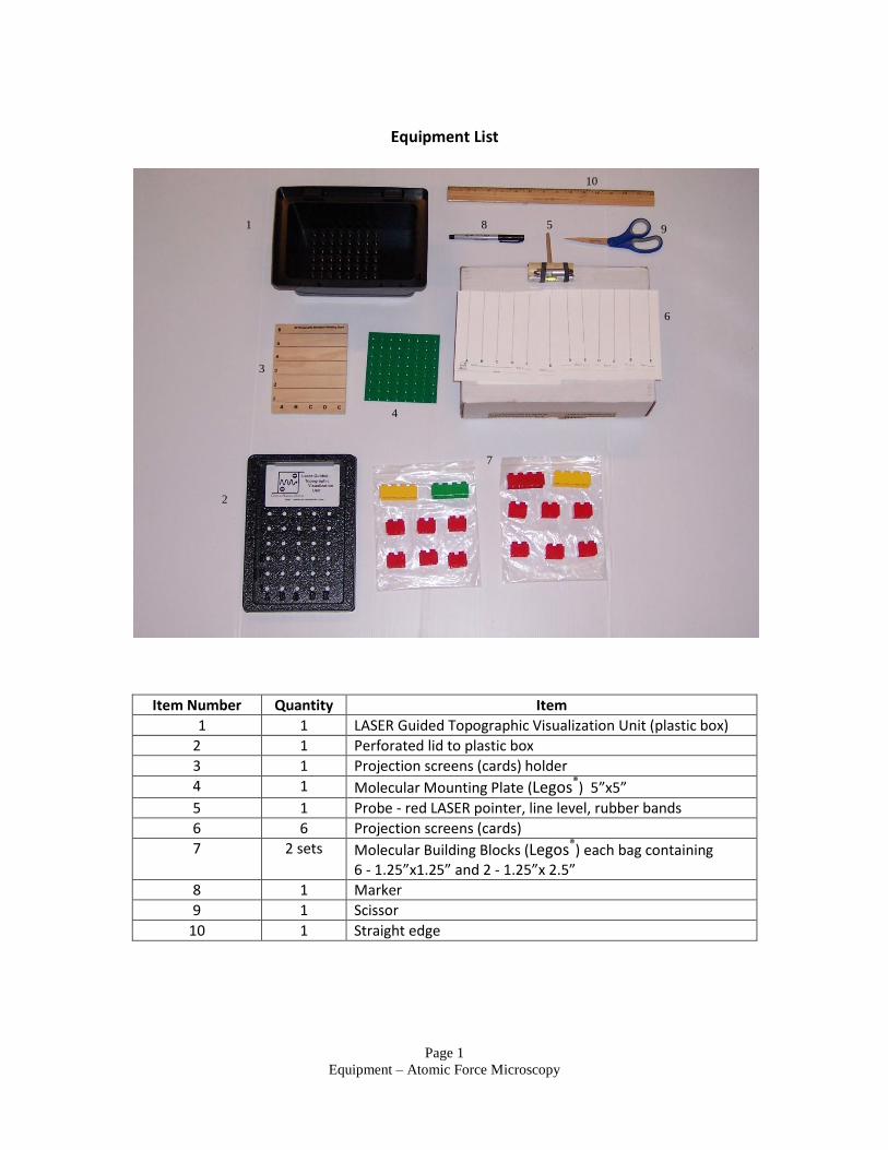
Page 1
Equipment – Atomic Force Microscopy
Equipment List
Item Number Quantity Item
1 1 LASER Guided Topographic Visualization Unit (plastic box)
2 1 Perforated lid to plastic box
3 1 Projection screens (cards) holder
4 1 Molecular Mounting Plate (Legos®) 5”x5”
5 1 Probe - red LASER pointer, line level, rubber bands
6 6 Projection screens (cards)
7 2 sets Molecular Building Blocks (Legos®) each bag containing 6 - 1.25”x1.25” and 2 - 1.25”x 2.5”
8 1 Marker
9 1 Scissor
10 1 Straight edge
1
3 4
2
5 8
6
7
3
4
10
9
Page 1
Student Section – Atomic Force Microscopy
ATOMIC FORCE MICROSCOPY Introduction In this activity you will use a special probe to “feel” the shape of a “molecule” that is invisible to you, the microscopist. In more technical language, you will map the topography of the surface of an unknown structure. First, you will use Legos® blocks to build a “molecule” or “molecules” within an enclosed box. You will then trade boxes with another team and try to discern the shape of the “molecule” or “molecules” that the other team designed. Feel free to try to make your “molecule” as difficult to map as possible. ***CAUTION: Never look into the LASER beam or point it at someone’s eye!*** Prepare your Sample
1. Open and unpack your LASER Guided Topographic Visualizing Unit (LGTVU). Within it you should find the following:
a. 2 bags of molecular building blocks (Legos®)
b. A Molecular Mounting Plate (Legos® base plate)
c. A probe (dowel rod mounted to a platform with a LASER and level)
d. A 3-D Topographic Simulation Mounting Board
e. Projection Screens (Cards with lines)
2. Using one bag of Legos® build a molecule or several separate molecules on the molecular mounting plate (Legos® base plate) in the bottom of the unit. Do not build on the areas with black X’s. If you choose to overhang any blocks, make sure that at least half of the block is supported by blocks below it.
3. Once you have designed your molecule, put the cover on. Make sure that row 1 on the cover is above the single row of X’s on the molecular mounting plate.
4. Find another team and trade boxes. ***From this point on, do not open the lid under ANY circumstances until you have completed building a model of what is inside.*** Collect Baseline Data
1. Find a Projection Screen (card with vertical lines), fold it on the dotted line, and insert the folded edge in the slotted pegs or white card holder (depending on which model you have) found on the top of the LGTVU. Make sure the vertical lines are aligned with the rows of holes.
2. You can begin taking your readings by inserting your probe and platform mounted LASER in hole A1. Aim the LASER toward the screen. You know that there will be no molecules in row 1 as it was a restricted area. Press the platform down until the probe touches the surface.
Page 2
Student Section - Atomic Force Microscopy
3. Once the probe is touching the surface, you may click the LASER on and project it onto the screen. You will need to align it in two directions:
a. Orient the LASER beam so that it falls on the appropriate vertical line of the Projection Screen (the line marked A).
b. Gently tilt the platform until the bubble in the level is centered.
4. Once you have aligned the probe, mark the spot on the Projection Screen where the LASER hits it.
5. Repeat the above procedure for all of the remaining points in row 1 (B1, C1, D1 and E1). This will be your baseline, or the topography where no bocks are present.
6. Remove this card and write “1” for the row number.
Collect Topographic Data
1. Place a new Projection Screen in the holders and repeat the above procedure in columns A-E, row 2. When you are done, put “2” for the row number.
2. Repeat in each row up to and including row 6. Remember to label each card.
Display your Data
1. Go back to your baseline card (Row 1). The 5 points should be roughly horizontal. Connect the points using a pencil. Discuss with your lab partners how to do this. Using a scissors, cut the card along this line.
2. Connect the points on the other data cards. Once you and your lab partners have agreed upon the data cards, you may cut each one along the line you drew and keep the bottom part.
3. You can now make a paper model of your molecular topography by using the 3-D Topographic Simulation Mounting Board. Start out by inserting your cut out screen for row 1 in the slot labeled “1.” Remember that this is your baseline, or the topography where no bocks are present.
4. Insert the remaining cut out screens for each row into the Mounting Board. Be sure to get each screen into the correct slot.
Assemble a Molecular Model
Now that your team has assembled the data on the unknown “molecule,” you can use this to build a model with the spare bag of Molecular Building Blocks and Molecular Mounting Plate. Do not look into the box until your entire team agrees on the model. When you agree, open the box and compare the formation inside with your model. Keep all Legos® structures intact for the analysis section.
Page 3
Student Section - Atomic Force Microscopy
ANALYSIS 1. Was your model identical to the unknown? 2. Talk to other teams about their results. For those teams that did not accurately
replicate the molecule and did the procedure correctly, what went wrong? 3. What topographical features were easy to map? Which aspects were difficult or
impossible? 4. What is “resolution”? Explain this term in your own words. 5. Is the horizontal resolution different than the vertical resolution? If so, which is
better? Explain your answer. 6. Was the resolution of this LASER Guided Topographic Visualization Unit a factor in
building an accurate model? 7. How would you redesign the Unit to get better resolution?
Page 4
Student Section - Atomic Force Microscopy
(POST-LAB WORKSHEET)
AFM: A MICROSCOPE THAT CAN IMAGE MOLECULES In the previous activity, you used a probe attached to a LASER to determine the topography of a Legos® molecule. You probably found that although the imaging unit was able to detect large features in the topography, it did not allow you to resolve the fine details of the molecules such as narrow crevices and the exact locations of edges of the blocks. Imagine what it would be like if we could shrink our probe to be less than 100 atoms wide. What advantage would this give? Imagine that instead of taking readings every inch, we could drag this probe across the surface of the molecule. What advantage would this give? If the probe was being dragged across the surface of the material (or the material was being dragged under the probe), how would you design the probe in order to read all heights? If you answered the questions above correctly, you have designed the rudiments of the Atomic Force Microscope (AFM). If you could not answer them, read on, perhaps soon you can go back and answer them.
Page 5
Student Section - Atomic Force Microscopy
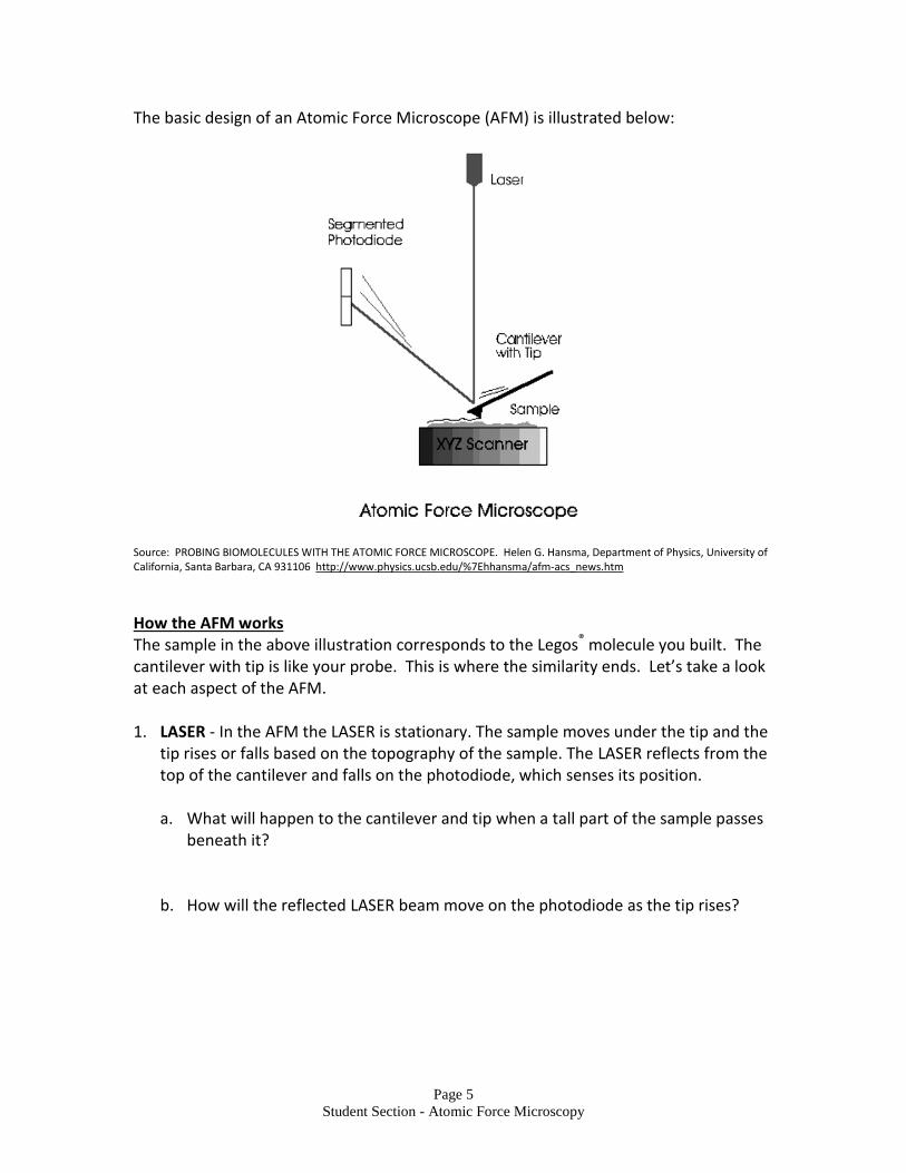
The basic design of an Atomic Force Microscope (AFM) is illustrated below:
Source: PROBING BIOMOLECULES WITH THE ATOMIC FORCE MICROSCOPE. Helen G. Hansma, Department of Physics, University of California, Santa Barbara, CA 931106 http://www.physics.ucsb.edu/%7Ehhansma/afm-acs_news.htm
How the AFM works The sample in the above illustration corresponds to the Legos® molecule you built. The cantilever with tip is like your probe. This is where the similarity ends. Let’s take a look at each aspect of the AFM. 1. LASER - In the AFM the LASER is stationary. The sample moves under the tip and the
tip rises or falls based on the topography of the sample. The LASER reflects from the top of the cantilever and falls on the photodiode, which senses its position. a. What will happen to the cantilever and tip when a tall part of the sample passes
beneath it?
b. How will the reflected LASER beam move on the photodiode as the tip rises?
Page 6
Student Section - Atomic Force Microscopy
2. Cantilever – The cantilever is shaped like a diving board and it acts like a very soft spring. When the cantilever is lowered and the tip makes contact with surface, it bends so that the force between the tip and the surface is very low (nano-Newtons).
a. What might happen if the force between the tip and the sample gets too large? b. How would you increase the force between the tip and the surface? Decrease
it? a. What will happen to the position of the reflected LASER beam on the photodiode
as you increase the force? Decrease it? b. Describe how you would keep the force between the tip and the sample
constant while the sample was scanning under the tip.
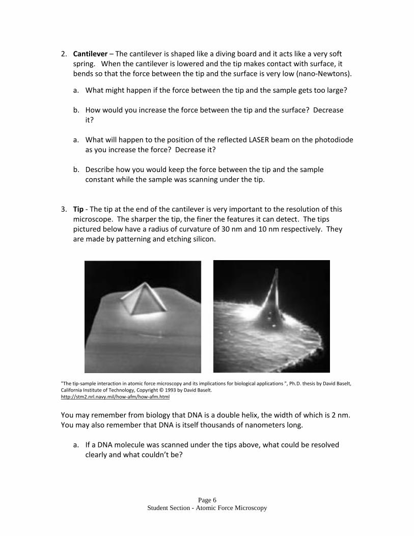
3. Tip - The tip at the end of the cantilever is very important to the resolution of this microscope. The sharper the tip, the finer the features it can detect. The tips pictured below have a radius of curvature of 30 nm and 10 nm respectively. They are made by patterning and etching silicon.
"The tip-sample interaction in atomic force microscopy and its implications for biological applications ", Ph.D. thesis by David Baselt, California Institute of Technology, Copyright © 1993 by David Baselt. http://stm2.nrl.navy.mil/how-afm/how-afm.html
You may remember from biology that DNA is a double helix, the width of which is 2 nm. You may also remember that DNA is itself thousands of nanometers long.
a. If a DNA molecule was scanned under the tips above, what could be resolved
clearly and what couldn’t be?

Page 7
Student Section - Atomic Force Microscopy
b. What differences would you expect between images generated with the two tips?
Page 8
Student Section - Atomic Force Microscopy
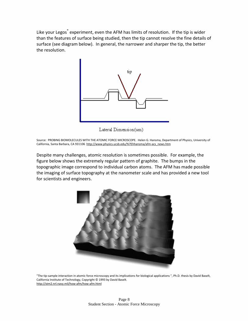
Like your Legos® experiment, even the AFM has limits of resolution. If the tip is wider than the features of surface being studied, then the tip cannot resolve the fine details of surface (see diagram below). In general, the narrower and sharper the tip, the better the resolution.
Source: PROBING BIOMOLECULES WITH THE ATOMIC FORCE MICROSCOPE. Helen G. Hansma, Department of Physics, University of California, Santa Barbara, CA 931106 http://www.physics.ucsb.edu/%7Ehhansma/afm-acs_news.htm
Despite many challenges, atomic resolution is sometimes possible. For example, the figure below shows the extremely regular pattern of graphite. The bumps in the topographic image correspond to individual carbon atoms. The AFM has made possible the imaging of surface topography at the nanometer scale and has provided a new tool for scientists and engineers.
"The tip-sample interaction in atomic force microscopy and its implications for biological applications ", Ph.D. thesis by David Baselt, California Institute of Technology, Copyright © 1993 by David Baselt. http://stm2.nrl.navy.mil/how-afm/how-afm.html
Page 9
Student Section - Atomic Force Microscopy
ANALYSIS 1. In your own words describe the similarities between the LASER Guided Topographic
Visualization Unit and the AFM. 2. In your own words describe the differences between the LASER Guided Topographic
Visualization Unit and the AFM. 3. Describe the general principles of how an AFM works. 4. What is “resolution” and what determines the resolution of an AFM? 5. Besides the size of the molecules, can you think of another limitation of using the
AFM to investigate biological materials?