title 14: aeronautics and space - commercial space...
TRANSCRIPT
e-CFR Data is current as of April 8, 2010
TITLE 14--Aeronautics and Space
CHAPTER III--COMMERCIAL SPACE TRANSPORTATION, FEDERAL AVIATION ADMINISTRATION, DEPARTMENT OF TRANSPORTATION
TABLE OF CONTENTS
PART 400—BASIS AND SCOPE..................................................................................2PART 401—ORGANIZATION AND DEFINITIONS..................................................3PART 404—REGULATIONS AND LICENSING REQUIREMENTS......................10PART 405—INVESTIGATIONS AND ENFORCEMENT.........................................14PART 406—INVESTIGATIONS, ENFORCEMENT, AND ADMINISTRATIVE
REVIEW.................................................................................................16PART 413—LICENSE APPLICATION PROCEDURES...........................................51PART 414—SAFETY APPROVALS...........................................................................58PART 415—LAUNCH LICENSE................................................................................68PART 417—LAUNCH SAFETY.................................................................................99PART 420—LICENSE TO OPERATE A LAUNCH SITE.......................................490PART 431—LAUNCH AND REENTRY OF A REUSABLE LAUNCH VEHICLE
(RLV)....................................................................................................571PART 433—LICENSE TO OPERATE A REENTRY SITE......................................592PART 435—REENTRY OF A REENTRY VEHICLE OTHER THAN A REUSABLE
LAUNCH VEHICLE (RLV)................................................................594PART 437—EXPERIMENTAL PERMITS................................................................599PART 440—FINANCIAL RESPONSIBILITY..........................................................615PART 460—HUMAN SPACE FLIGHT REQUIREMENTS....................................656
1

PART 400—BASIS AND SCOPE
Section Contents§ 400.1 Basis. § 400.2 Scope.
Authority: 49 U.S.C. 70101–70121.
Source: Docket No. 43810, 53 FR 11013, Apr. 4, 1988, unless otherwise noted.
§ 400.1 Basis.
The basis for the regulations in this chapter is the Commercial Space Launch Act of 1984, and applicable treaties and international agreements to which the United States is party.
§ 400.2 Scope.
These regulations set forth the procedures and requirements applicable to the authorization and supervision under 49 U.S.C. Subtitle IX, chapter 701, of commercial space transportation activities conducted in the United States or by a U.S. citizen. The regulations in this chapter do not apply to amateur rockets activities, as defined in 14 CFR 1.1, or to space activities carried out by the United States Government on behalf of the United States Government.
[Doc. No. FAA–2007–27390, 73 FR 73782, Dec. 4, 2008]
2

PART 401—ORGANIZATION AND DEFINITIONS
Section Contents§ 401.1 The Office of Commercial Space Transportation. § 401.3 The Associate Administrator for Commercial Space Transportation. § 401.5 Definitions.
Authority: 49 U.S.C. 70101–70121.
Source: Docket No. 43810, 53 FR 11013, Apr. 4, 1988, unless otherwise noted.
§ 401.1 The Office of Commercial Space Transportation.
The Office of Commercial Space Transportation, referred to in these regulations as the “Office,” is a line of business within the Federal Aviation Administration and is located in the Federal Aviation Administration Headquarters, 800 Independence Avenue, SW., Room 331, Washington, DC 20591.
[Amdt. 401–3, 68 FR 35289, June 13, 2003]
§ 401.3 The Associate Administrator for Commercial Space Transportation.
The Office is headed by an Associate Administrator to exercise the Secretary's authority to license or permit and otherwise regulate commercial space transportation and to discharge the Secretary's responsibility to encourage, facilitate, and promote commercial space transportation by the United States private sector.
[Doc. No. FAA–2006–24197, 72 FR 17016, Apr. 6, 2007]
§ 401.5 Definitions.
As used in this chapter—
Act means 49 U.S.C. Subtitle IX, Commercial Space Transportation, ch. 701—Commercial Space Launch Activities, 49 U.S.C. 70101–70121.
Associate Administrator means the Associate Administrator for Commercial Space Transportation, Federal Aviation Administration, or any person designated by the Associate Administrator to exercise the authority or discharge the responsibilities of the Associate Administrator.
Casualty means serious injury or death.
3

Contingency abort means cessation of vehicle flight during ascent or descent in a manner that does not jeopardize public health and safety and the safety of property, in accordance with mission rules and procedures. Contingency abort includes landing at an alternative location that has been designated as a contingency abort location in advance of vehicle flight.
Crew means any employee or independent contractor of a licensee, transferee, or permittee, or of a contractor or subcontractor of a licensee, transferee, or permittee, who performs activities in the course of that employment or contract directly relating to the launch, reentry, or other operation of or in a launch vehicle or reentry vehicle that carries human beings. A crew consists of flight crew and any remote operator.
Emergency abort means cessation of vehicle flight during ascent or descent in a manner that minimizes risk to public health and safety and the safety of property. Emergency abort involves failure of a vehicle, safety-critical system, or flight safety system such that contingency abort is not possible.
Equivalent level of safety means an approximately equal level of safety as determined by qualitative or quantitative means.
Expendable launch vehicle means a launch vehicle whose propulsive stages are flown only once.
Experimental permit or permit means an authorization by the FAA to a person to launch or reenter a reusable suborbital rocket.
Federal launch range means a launch site, from which launches routinely take place, that is owned and operated by the government of the United States.
Flight crew means crew that is on board a vehicle during a launch or reentry.
Flight safety system means a system designed to limit or restrict the hazards to public health and safety and the safety of property presented by a launch vehicle or reentry vehicle while in flight by initiating and accomplishing a controlled ending to vehicle flight. A flight safety system may be destructive resulting in intentional break up of a vehicle or nondestructive, such as engine thrust termination enabling vehicle landing or safe abort capability.
Hazardous materials means hazardous materials as defined in 49 CFR 172.101.
Human space flight incident means an unplanned event that poses a high risk of causing a serious or fatal injury to a space flight participant or crew.
Instantaneous impact point means an impact point, following thrust termination of a launch vehicle, calculated in the absence of atmospheric drag effects.
4
Launch means to place or try to place a launch vehicle or reentry vehicle and any payload from Earth in a suborbital trajectory, in Earth orbit in outer space, or otherwise in outer space, and includes preparing a launch vehicle for flight at a launch site in the United States. Launch includes the flight of a launch vehicle and includes pre- and post-flight ground operations as follows:
(1) Beginning of launch. (i) Under a license, launch begins with the arrival of a launch vehicle or payload at a U.S. launch site.
(ii) Under a permit, launch begins when any pre-flight ground operation at a U.S. launch site meets all of the following criteria:
(A) Is closely proximate in time to flight,
(B) Entails critical steps preparatory to initiating flight,
(C) Is unique to space launch, and
(D) Is inherently so hazardous as to warrant the FAA's regulatory oversight.
(2) End of launch. (i) For launch of an orbital expendable launch vehicle (ELV), launch ends after the licensee's last exercise of control over its launch vehicle.
(ii) For launch of an orbital reusable launch vehicle (RLV) with a payload, launch ends after deployment of the payload. For any other orbital RLV, launch ends upon completion of the first sustained, steady-state orbit of an RLV at its intended location.
(iii) For a suborbital ELV or RLV launch, launch ends after reaching apogee if the flight includes a reentry, or otherwise after vehicle landing or impact on Earth, and after activities necessary to return the vehicle to a safe condition on the ground.
Launch accident means
(1) An event that causes a fatality or serious injury (as defined in 49 CFR 830.2) to any person who is not associated with the flight;
(2) An event that causes damage estimated to exceed $25,000 to property not associated with the flight that is not located at the launch site or designated recovery area;
(3) An unplanned event occurring during the flight of a launch vehicle resulting in the impact of a launch vehicle, its payload or any component thereof:
(i) For an expendable launch vehicle, outside designated impact limit lines; and
(ii) For a reusable launch vehicle, outside a designated landing site.
5
(4) For a launch that takes place with a person on board, a fatality or serious injury to a space flight participant or crew member.
Launch incident means an unplanned event during the flight of a launch vehicle, other than a launch accident, involving a malfunction of a flight safety system or safety-critical system, or a failure of the licensee's or permittee's safety organization, design, or operations.
Launch operator means a person who conducts or who will conduct the launch of a launch vehicle and any payload.
Launch site means the location on Earth from which a launch takes place (as defined in a license the Secretary issues or transfers under this chapter) and necessary facilities at that location.
Launch site safety assessment means an FAA assessment of a Federal launch range to determine if the range meets FAA safety requirements. A difference between range practice and FAA requirements is documented in the LSSA.
Launch vehicle means a vehicle built to operate in, or place a payload in, outer space or a suborbital rocket.
Mishap means a launch or reentry accident, launch or reentry incident, launch site accident, failure to complete a launch or reentry as planned, or an unplanned event or series of events resulting in a fatality or serious injury (as defined in 49 CFR 830.2), or resulting in greater than $25,000 worth of damage to a payload, a launch or reentry vehicle, a launch or reentry support facility or government property located on the launch or reentry site.
Nominal means, in reference to launch vehicle performance, trajectory, or stage impact point, a launch vehicle flight where all vehicle aerodynamic parameters are as expected, all vehicle internal and external systems perform exactly as planned, and there are no external perturbing influences other than atmospheric drag and gravity.
Operation of a launch site means the conduct of approved safety operations at a permanent site to support the launching of vehicles and payloads.
Operation of a reentry site means the conduct of safety operations at a permanent site on Earth at which a reentry vehicle and its payload, if any, is intended to land.
Operator means a holder of a license or permit under 49 U.S.C. Subtitle IX, chapter 701.
Payload means an object that a person undertakes to place in outer space by means of a launch vehicle, including components of the vehicle specifically designed or adapted for that object.
6
Person means an individual or an entity organized or existing under the laws of a state or country.
Populated area means—
(1) An outdoor location, structure, or cluster of structures that may be occupied by people;
(2) Sections of roadways and waterways that are frequented by automobile and boat traffic; or
(3) Agricultural lands, if routinely occupied by field workers.
Pilot means a flight crew member who has the ability to control, in real time, a launch or reentry vehicle's flight path.
Public safety means, for a particular licensed launch, the safety of people and property that are not involved in supporting the launch and includes those people and property that may be located within the boundary of a launch site, such as visitors, individuals providing goods or services not related to launch processing or flight, and any other launch operator and its personnel.
Reenter; reentry means to return or attempt to return, purposefully, a reentry vehicle and its payload, if any, from Earth orbit or from outer space to Earth. The term “reenter; reentry” includes activities conducted in Earth orbit or outer space to determine reentry readiness and that are critical to ensuring public health and safety and the safety of property during reentry flight. The term “reenter; reentry” also includes activities conducted on the ground after vehicle landing on Earth to ensure the reentry vehicle does not pose a threat to public health and safety or the safety of property.
Reentry accident means
(1) Any unplanned event occurring during the reentry of a reentry vehicle resulting in the impact of the reentry vehicle, its payload, or any component thereof, outside a designated reentry site;
(2) An event that causes a fatality or serious injury (as defined in 49 CFR 830.2) to any person who is not associated with the reentry;
(3) An event that causes damage estimated to exceed $25,000 to property not associated with the reentry and not located within a designated reentry site; and
(4) For a reentry that takes place with a person on board, a fatality or serious injury to a space flight participant or crew member.
7

Reentry incident means any unplanned event occurring during the reentry of a reentry vehicle, other than a reentry accident, involving a malfunction of a reentry safety-critical system or failure of the licensee's or permittee's safety organization, procedures, or operations.
Reentry operator means a person responsible for conducting the reentry of a reentry vehicle as specified in a license issued by the FAA.
Reentry site means the location on Earth where a reentry vehicle is intended to return. It includes the area within three standard deviations of the intended landing point (the predicted three-sigma footprint).
Reentry vehicle means a vehicle designed to return from Earth orbit or outer space to Earth substantially intact. A reusable launch vehicle that is designed to return from Earth orbit or outer space to Earth substantially intact is a reentry vehicle.
Remote operator means a crew member who
(1) Has the ability to control, in real time, a launch or reentry vehicle's flight path, and
(2) Is not on board the controlled vehicle.
Reusable launch vehicle (RLV) means a launch vehicle that is designed to return to Earth substantially intact and therefore may be launched more than one time or that contains vehicle stages that may be recovered by a launch operator for future use in the operation of a substantially similar launch vehicle.
Risk means a measure that accounts for both the probability of occurrence of a hazardous event and the consequence of that event to persons or property.
Safety critical means essential to safe performance or operation. A safety critical system, subsystem, component, condition, event, operation, process, or item is one whose proper recognition, control, performance, or tolerance is essential to ensuring public safety. Something that is safety critical item creates a safety hazard or provide protection from a safety hazard.
Sigma means a single standard deviation from a fixed value, such as a mean.
Space flight participant means an individual, who is not crew, carried aboard a launch vehicle or reentry vehicle.
State and United States means, when used in a geographical sense, the several States, the District of Columbia, the Commonwealth of Puerto Rico, American Samoa, the United States Virgin Islands, Guam, and any other commonwealth, territory, or possession of the United States; and
8

United States citizen means:
(1) Any individual who is a citizen of the United States;
(2) Any corporation, partnership, joint venture, association, or other entity organized or existing under the laws of the United States or any State; and
(3) Any corporation, partnership, joint venture, association, or other entity which is organized or exists under the laws of a foreign nation, if the controlling interest in such entity is held by an individual or entity described in paragraph (1) or (2) of this definition. Controlling interest means ownership of an amount of equity in such entity sufficient to direct management of the entity or to void transactions entered into by management. Ownership of at least fifty-one percent of the equity in an entity by persons described in paragraph (1) or (2) of this definition creates a rebuttable presumption that such interest is controlling.
Suborbital rocket means a vehicle, rocket-propelled in whole or in part, intended for flight on a suborbital trajectory, and the thrust of which is greater than its lift for the majority of the rocket-powered portion of its ascent.
Suborbital trajectory means the intentional flight path of a launch vehicle, reentry vehicle, or any portion thereof, whose vacuum instantaneous impact point does not leave the surface of the Earth.
Validation means an evaluation to determine that each safety measure derived from a system safety process is correct, complete, consistent, unambiguous, verifiable, and technically feasible. Validation ensures that the right safety measure is implemented, and that the safety measure is well understood.
Vehicle safety operations personnel means those persons whose job performance is critical to public health and safety or the safety of property during RLV or reentry operations.
Verification means an evaluation to determine that safety measures derived from a system safety process are effective and have been properly implemented. Verification provides measurable evidence that a safety measure reduces risk to acceptable levels.
[Doc. No. FAA–1999–5535, 65 FR 56656, Sept. 19, 2000, as amended by Amdt. 401–2, 65 FR 62861, Oct. 19, 2000; Amdt. 401–4, 71 FR 50530, Aug. 25, 2006; 71 FR 75631, Dec. 15, 2006; Amdt. 401–5, 72 FR 17016, Apr. 6, 2007; Amdt. 401–6, 73 FR 73782, Dec. 4, 2008]
9

PART 404—REGULATIONS AND LICENSING REQUIREMENTS
Section Contents
Subpart A—General§ 404.1 Scope. § 404.3 Filing of petitions to the Associate Administrator. § 404.5 Action on petitions.
Subpart B—Rulemaking§ 404.11 General. § 404.13 Petitions for extension of time to comment. § 404.15 Consideration of comments received. § 404.17 Additional rulemaking proceedings. § 404.19 Hearings.
Authority: 49 U.S.C. 70101–70121.
Source: Docket No. 43810, 53 FR 11013, Apr. 4, 1988, unless otherwise noted.
Subpart A—General
§ 404.1 Scope.
This part establishes procedures for issuing regulations to implement 49 U.S.C. Subtitle IX, chapter 701, and for eliminating or waiving requirements for licensing or permitting of commercial space transportation activities under that statute.
[Doc. No. FAA–2006–24197, 72 FR 17016, Apr. 6, 2007]
§ 404.3 Filing of petitions to the Associate Administrator.
(a) Any person may petition the Associate Administrator to:
(1) Issue, amend, or repeal a regulation to eliminate as a requirement for a license or permit any requirement of Federal law applicable to commercial space launch and reentry activities and the operation of launch and reentry sites;
(2) Waive any such requirement in the context of a specific application for a license or permit; or
(3) Waive the requirement for a license.
10
(b) Each petition filed under this section must:
(1) Be submitted in duplicate to the:
(i) Office of Commercial Space Transportation, Federal Aviation Administration, 800 Independence Avenue, SW., Room 331, Washington, DC 20591; or
(ii) Be submitted in duplicate to the U.S. Department of Transportation, Docket Operations, West Building Ground Floor, Room W12–140, 1200 New Jersey Avenue, SE., Washington, DC 20590;
(2) Set forth the text or substance of the regulation or amendment proposed, the regulation to be repealed, the licensing or permitting requirement to be eliminated or waived, or the type of license or permit to be waived;
(3) In the case of a petition for a waiver of a particular licensing or permitting requirement, explain the nature and extent of the relief sought;
(4) Contain any facts, views, and data available to the petitioner to support the action requested; and
(5) In the case of a petition for a waiver, be submitted at least 60 days before the proposed effective date of the waiver unless good cause for later submission is shown in the petition.
(c) A petition for rulemaking filed under this section must contain a summary, which the Associate Administrator may cause to be published in theFederal Register,which includes:
(1) A brief description of the general nature of the action requested; and
(2) A brief description of the pertinent reasons presented in the petition for instituting the rulemaking.
(d) A petition filed under this section may request, under 14 CFR 413.9, that the Department withhold certain trade secrets or proprietary commercial or financial data from public disclosure.
[Doc. No. FAA–2005–21234, 71 FR 51971, Aug. 31, 2006, as amended at 72 FR 68475, Dec. 5, 2007]
§ 404.5 Action on petitions.
(a) General. No public hearing, argument or other proceeding is held on a petition before its disposition under this section.
11

(b) Grants. In the case of a petition for a waiver, the Associate Administrator may grant the waiver if the Associate Administrator determines that the waiver is in the public interest and will not jeopardize public health and safety, the safety or property, or any national security or foreign policy interest of the United States. In all other cases, if the Associate Administrator determines that the petition contains adequate justification, the Associate Administrator initiates a rulemaking action under Subpart B of this part.
(c) Denials. If the Associate Administrator determines that the petition does not justify initiating rulemaking action or granting the waiver, the petition is denied.
(d) Notification. Whenever the Associate Administrator determines that a petition should be granted or denied, the petitioner is notified of the Associate Administrator's action and the reasons supporting it.
(e) Reconsideration. Any person may petition FAA to reconsider a denial of a petition the person had filed. The petitioner must send a request for reconsideration within 60 days after being notified of the denial to the same address to which the original petition went. For FAA to accept the petition, the petitioner must show the following:
(1) There is a significant additional fact and the reason it was not included in the original petition;
(2) FAA made an important factual error in our denial of the original petition; or
(3) The denial by the FAA is not in accordance with the applicable law and regulations.
[53 FR 11013, Apr. 4, 1988, as amended by Amdt. 404–2, 68 FR 35289, June 13, 2003; Amdt. 404–3, 71 FR 51971, Aug. 31, 2006]
Subpart B—Rulemaking
§ 404.11 General.
(a) Unless the Associate Administrator finds, for good cause, that notice is impractical, unnecessary, or contrary to the public interest, a notice of proposed rulemaking is issued and interested persons are invited to participate in proceedings related to each substantive rule proposed.
(b) Unless the Associate Administrator determines that notice and comment is necessary or desirable, interpretive rules, general statements of policy, and rules relating to organization, procedure, or practice are issued as final rules without notice or other proceedings.
(c) In the Associate Administrator's discretion, interested persons may be invited to participate in the rulemaking proceedings described in §404.19 of this Subpart.
12

[53 FR 11013, Apr. 4, 1988, as amended by Amdt. 404–2, 68 FR 35289, June 13, 2003]
§ 404.13 Petitions for extension of time to comment.
(a) Any person may petition the Associate Administrator for an extension of time to submit comments in response to a notice of proposed rulemaking. The petition shall be submitted in duplicate not less than three days before expiration of the time stated in the notice. The filing of the petition does not automatically extend the time for petitioner's comments.
(b) The Associate Administrator grants the petition only if the petitioner shows a substantive interest in the proposed rule and good cause for the extension, and if the extension is in the public interest. If an extension is granted, it is granted as to all persons and is published in theFederal Register.
[53 FR 11013, Apr. 4, 1988, as amended by Amdt. 404–2, 68 FR 35289, June 13, 2003]
§ 404.15 Consideration of comments received.
All timely comments are considered before final action is taken on a rulemaking proposal. Late filed comments may be considered to the extent possible, provided they do not cause undue additional expense or delay.
§ 404.17 Additional rulemaking proceedings.
The FAA may initiate other rulemaking proceedings, if necessary or desirable. For example, it may invite interested people to present oral arguments, participate in conferences, appear at informal hearings, or participate in any other proceedings.
[Doc. No. FAA–2006–24197, 72 FR 17016, Apr. 6, 2007]
§ 404.19 Hearings.
(a) Sections 556 and 557 of Title 5, United States Code, do not apply to hearings held under this part. As a fact-finding forum, each hearing held under this part is nonadversarial and there are no formal pleadings or adverse parties. Any rule issued in a proceeding in which a hearing is held is not based exclusively on the record of the hearing, but on the entire record of the rulemaking proceeding.
(b) The Associate Administrator designates a representative to conduct any hearing held under this part. The FAA Chief Counsel designates a legal officer for the hearing.
[53 FR 11013, Apr. 4, 1988, as amended by Amdt. 404–2, 68 FR 35289, June 13, 2003]
13

PART 405—INVESTIGATIONS AND ENFORCEMENT
Section Contents§ 405.1 Monitoring of licensed, permitted, and other activities. § 405.3 Authority to modify, suspend or revoke. § 405.5 Emergency orders.
Authority: 49 U.S.C. 70101–70121.
Source: Docket No. 43810, 53 FR 11014, Apr. 4, 1988, unless otherwise noted.
§ 405.1 Monitoring of licensed, permitted, and other activities.
Each licensee or permittee must allow access by and cooperate with Federal officers or employees or other individuals authorized by the Associate Administrator to observe licensed facilities and activities, including launch sites and reentry sites, as well as manufacturing, production, testing, and training facilities, or assembly sites used by any contractor, licensee, or permittee to produce, assemble, or test a launch or reentry vehicle and to integrate a payload with its launch or reentry vehicle. Observations are conducted to monitor the activities of the licensee, permittee, or contractor at such time and to such extent as the Associate Administrator considers reasonable and necessary to determine compliance with the license or permit or to perform the Associate Administrator's responsibilities pertaining to payloads for which no Federal license, authorization, or permit is required.
[Doc. No. FAA–2006–24197, 72 FR 17016, Apr. 6, 2007]
§ 405.3 Authority to modify, suspend or revoke.
(a) The FAA may modify a license or permit issued under this chapter upon application by the licensee or permittee or upon the FAA's own initiative, if the FAA finds that the modification is consistent with the requirements of the Act.
(b) The FAA may suspend or revoke any license or permit issued to such licensee or permittee under this chapter if the FAA finds that a licensee or permittee has substantially failed to comply with any requirement of the Act, any regulation issued under the Act, the terms and conditions of a license or permit, or any other applicable requirement; or that public health and safety, the safety of property, or any national security or foreign policy interest of the United States so require.
(c) Unless otherwise specified by the Office, any modification, suspension or revocation made by the Office under this section:
14
(1) Takes effect immediately; and
(2) Continues in effect during any review of such action under Part 406 of this chapter.
(d) Whenever the FAA takes any action under this section, the FAA immediately notifies the licensee or permittee in writing of the FAA's finding and the action, which the FAA has taken or proposes to take regarding such finding.
[Docket No. 43810, 53 FR 11014, Apr. 4, 1988, as amended by Amdt. 405–3, 72 FR 17016, Apr. 6, 2007]
§ 405.5 Emergency orders.
The Associate Administrator may immediately terminate, prohibit, or suspend a licensed or permitted launch, reentry, or operation of a launch or reentry site if the Associate Administrator determines that—
(a) The licensed or permitted launch, reentry, or operation of a launch or reentry site is detrimental to public health and safety, the safety of property, or any national security or foreign policy interest of the United States; and
(b) The detriment cannot be eliminated effectively through the exercise of other authority of the Office.
[53 FR 11014, Apr. 4, 1988, as amended by Amdt. 405–1, 65 FR 56657, Sept. 19, 2000; Amdt. 405–3, 72 FR 17017, Apr. 6, 2007]
15

PART 406—INVESTIGATIONS, ENFORCEMENT, AND ADMINISTRATIVE REVIEW
Section Contents
Subpart A—Investigations and Enforcement
§ 406.1 Hearings in license, permit, and payload actions. § 406.3 Submissions; oral presentation in license, permit, and payload actions. § 406.5 Administrative law judge's recommended decision in license, permit, and payload actions. § 406.7 [Reserved] § 406.9 Civil penalties. §§ 406.10-406.100 [Reserved]
Subpart B—Rules of Practice in FAA Space Transportation Adjudications
§ 406.101 Applicability. § 406.103 Definitions that apply in part 406. § 406.105 Separation of functions for prosecuting civil penalties and advising the FAA decisionmaker. § 406.107 Appearances of parties, and attorneys and representatives. § 406.109 Administrative law judges—powers and limitations. § 406.111 Signing documents. § 406.113 Filing documents with the Docket Management System (DMS) and sending documents to the administrative law judge and Assistant Chief Counsel for Litigation.§ 406.115 Serving documents on other parties. § 406.117 Confidential information. § 406.119 Computation of time. § 406.121 Extension of time. § 406.123 Waivers. § 406.127 Complaint and answer in civil penalty adjudications. § 406.133 Amendment of pleadings. § 406.135 Withdrawal of complaint or request for hearing. § 406.137 Intervention. § 406.139 Joint procedural or discovery schedule. § 406.141 Motions. § 406.143 Discovery. § 406.147 Notice of hearing. § 406.149 Evidence. § 406.151 Standard of proof. § 406.153 Burden of proof. § 406.155 Offer of proof. § 406.157 Expert or opinion witnesses. § 406.159 Subpoenas. § 406.161 Witness fees. § 406.163 Record. § 406.165 Argument before the administrative law judge. § 406.167 Initial decision. § 406.173 Interlocutory appeals. § 406.175 Appeal from initial decision. § 406.177 Petition to reconsider or modify a final decision and order of the FAA decisionmaker on appeal.
16

§ 406.179 Judicial review of a final decision and order.
Authority: 49 U.S.C. 70101–70121.
Source: Docket No. FAA–2001–8607, 66 FR 2180, Jan. 10, 2001, unless otherwise noted.
Subpart A—Investigations and Enforcement
§ 406.1 Hearings in license, permit, and payload actions.
(a) Pursuant to 49 U.S.C. 70110, the following are entitled to a determination on the record after an opportunity for a hearing in accordance with 5 U.S.C. 554.
(1) An applicant for a license and a proposed transferee of a license regarding any decision to issue or transfer a license with conditions or to deny the issuance or transfer of such license;
(2) An owner or operator of a payload regarding any decision to prevent the launch or reentry of the payload;
(3) A licensee regarding any decision to suspend, modify, or revoke a license or to terminate, prohibit, or suspend any licensed activity;
(4) An applicant for a permit regarding an FAA decision to issue a permit with conditions or to deny the issuance of the permit; and
(5) A permittee regarding any decision to suspend, modify, or revoke a permit or to terminate, prohibit, or suspend any permitted activity.
(b) An administrative law judge will be designated to preside over any hearing held under this part.
[Docket No. FAA–2001–8607, 66 FR 2180, Jan. 10, 2001, as amended by Amdt. 406–4, 72 FR 17017, Apr. 6, 2007]
§ 406.3 Submissions; oral presentation in license, permit, and payload actions.
(a) The FAA will make decisions about license, permit, and payload actions under this subpart based on written submissions unless the administrative law judge requires an oral presentation.
17
(b) Submissions must include a detailed exposition of the evidence or arguments supporting the petition. Where an applicant must demonstrate an equivalent level of safety or fidelity, the applicant must make a clear and convincing demonstration.
(c) Petitions shall be filed as soon as practicable, but in no event more than 30 days after issuance of decision or finding under §406.1.
[Docket No. FAA–2001–8607, 66 FR 2180, Jan. 10, 2001, as amended by Amdt. 406–3, 71 FR 50530, Aug. 25, 2006; Amdt. 406–4, 72 FR 17017, Apr. 6, 2007]
§ 406.5 Administrative law judge's recommended decision in license, permit, and payload actions.
(a) The Associate Administrator, who shall make the final decision on the matter at issue, shall review the recommended decision of the administrative law judge. The Associate Administrator shall make such final decision within thirty days of issuance of the recommended decision.
(b) The authority and responsibility to review and decide rests solely with the Associate Administrator and may not be delegated.
§ 406.7 [Reserved]
§ 406.9 Civil penalties.
(a) Civil penalty liability. Under 49 U.S.C. 70115(c), a person found by the FAA to have violated a requirement of the Act, a regulation issued under the Act, or any term or condition of a license or permit issued or transferred under the Act, is liable to the United States for a civil penalty of not more than $100,000 for each violation, as adjusted for inflation. A separate violation occurs for each day the violation continues.
(b) Delegations. The authority to impose civil penalties is exercised by an agency attorney as described in §406.105.
(c) Notice of proposed civil penalty. A civil penalty action is initiated when the agency attorney advises a person, referred to as the respondent, of the charges or other reasons upon which the FAA bases the proposed action and allows the respondent to answer the charges and to be heard as to why the civil penalty should not be imposed. A notice of proposed civil penalty states the facts alleged; any requirement of the Act, a regulation issued under the Act, or any term or condition of a license or permit issued or transferred under the Act allegedly violated by the respondent; and the amount of the proposed civil penalty. Not later than 30 days after receipt of the notice of proposed civil penalty the respondent may elect to proceed by one or more of the following:
18

(1) Pay the amount of the proposed civil penalty or an agreed upon amount, in which case the agency attorney will issue either an order imposing civil penalty or a compromise order in that amount.
(2) Submit to the agency attorney one of the following:
(i) Written information, including documents and witnesses statements, demonstrating that a violation did not occur or that a penalty, or the amount of the proposed penalty, is not warranted by the circumstances.
(ii) A written request to reduce the proposed civil penalty, the amount of reduction, and the reasons and any document supporting a reduction of the proposed civil penalty, including records indicating a financial inability to pay or records showing that payment of the proposed civil penalty would prevent the person from continuing in business.
(iii) A written request for an informal conference to discuss the matter with the agency attorney and to submit relevant information.
(3) Request that a final notice of proposed civil penalty be issued so that the respondent may request a hearing in accordance with paragraph (g) of this section.
(d) Final notice of proposed civil penalty. A final notice of proposed civil penalty (final notice) provides the last opportunity for the respondent to request a hearing.
(1) The agency attorney issues a final notice if one of the following occurs:
(i) The respondent fails to respond to the notice of proposed civil penalty not later than 30 days after the date the respondent received the notice of proposed civil penalty.
(ii) The parties have not agreed to a resolution of the action after participating in informal procedures under paragraph (c)(2) of this section.
(iii) The respondent requests the issuance of a final notice in accordance with paragraph (c)(3) of this section.
(2) Not later than 15 days after the date the respondent received the final notice of proposed civil penalty, the respondent shall do one of the following:
(i) Submit the amount of the proposed civil penalty or an agreed-upon amount, in which case the agency attorney issues either an order imposing civil penalty or a compromise order in that amount.
(ii) Request a hearing in accordance with paragraph (g) of this section.
(e) Order imposing civil penalty. An order imposing civil penalty is the final order of the Secretary imposing a civil penalty. An order imposing civil penalty is issued for a
19

violation described in paragraph (a) of this section after notice and an opportunity for a hearing.
(1) The agency attorney either issues an order imposing civil penalty, or another document becomes an order imposing civil penalty, as described below.
(i) The agency attorney issues an order imposing civil penalty if, in response to a notice of proposed civil penalty or a final notice of proposed civil penalty, the respondent pays or agrees to pay a civil penalty in the amount proposed or an agreed upon amount (other than an agreement for a compromise order under paragraph (f) of this section).
(ii) Unless the respondent requests a hearing not later than 15 days after the date the respondent received a final notice of proposed civil penalty, the final notice of proposed civil penalty becomes an order imposing civil penalty.
(iii) Unless an appeal is filed with the FAA decisionmaker in accordance with §406.175, if the administrative law judge finds that a violation occurred and determines that a civil penalty, in an amount found appropriate by the administrative law judge, is warranted, an initial decision of an administrative law judge under subpart B of this part becomes an order imposing civil penalty.
(iv) Unless a complaint is filed with a United States district court in accordance with §406.176, if the FAA decisionmaker finds that a violation occurred and determines that a civil penalty, in an amount found appropriate by the FAA decisionmaker, is warranted, a final decision and order of the FAA decisionmaker under subpart B of this part becomes an order imposing civil penalty. If a person seeks judicial review not later than 60 days after the final decision and order has been served on the respondent, the final decision and order is stayed.
(2) [Reserved]
(f) Compromise order. The agency attorney at any time may agree to compromise any civil penalty with no finding of violation. Under such agreement, the agency attorney issues a compromise order stating:
(1) The respondent agrees to pay a civil penalty.
(2) The FAA makes no finding of a violation.
(3) The compromise order may not be used as evidence of a prior violation in any subsequent civil penalty action, license, or permit action.
(g) Request for hearing. Any respondent who has been issued a final notice of proposed civil penalty may, not later than 15 days after the date the respondent received the final notice, request a hearing under subpart B of this part.
20

(1) The respondent must file a written request for hearing with the Federal Docket Management System (U.S. Department of Transportation, Docket Operations, West Building Ground Floor, Room W12–140, 1200 New Jersey Avenue, SE., Washington, DC 20590) and must serve a copy of the request on the agency attorney. Sections 406.113 and 406.115 state how filing and service must be done.
(2) The request for hearing must be dated and signed.
(h) Method of payment. A respondent must pay a civil penalty by check or money order, payable to the Federal Aviation Administration.
(i) Collection of civil penalties. If a respondent does not pay a civil penalty imposed by an order imposing civil penalty or a compromise order within 60 days after service of the final order, the FAA may refer the order to the United States Department of Treasury or Department of Justice to collect the civil penalty.
(j) Exhaustion of administrative remedies. A respondent may seek judicial review of a final decision and order of the FAA decisionmaker as provided in §406.179. A respondent has not exhausted administrative remedies for purposes of judicial review if the final order is one of the following:
(1) An order imposing civil penalty issued by an agency attorney under paragraph (e)(1)(i) of this section.
(2) A final notice of proposed civil penalty that becomes an order imposing civil penalty under paragraph (e)(1)(ii) of this section.
(3) An initial decision of an administrative law judge that was not appealed to the FAA decisionmaker.
(4) A compromise order under paragraph (f) of this section.
(k) Compromise. The FAA may compromise or remit a civil penalty that has been proposed or imposed under this section.
[Docket No. FAA–2001–8607, 66 FR 2180, Jan. 10, 2001, as amended by Amdt. 406–4, 72 FR 17017, Apr. 6, 2007; 72 FR 68475, Dec. 5, 2007]
§§ 406.10-406.100 [Reserved]
Subpart B—Rules of Practice in FAA Space Transportation Adjudications
§ 406.101 Applicability.
21

(a) Adjudications to which these rules apply. These rules apply to the following adjudications:
(1) A civil penalty action in which the respondent has requested a hearing under §406.9.
(2) [Reserved]
(b) [Reserved]
§ 406.103 Definitions that apply in part 406.
For the purpose of this part:
Administrative law judge means an administrative law judge appointed pursuant to the provisions of 5 U.S.C. 3105.
Attorney means a person licensed by a state, the District of Columbia, or a territory of the United States to practice law or appear before the courts of that state or territory.
Complainant in a civil penalty action means the proponent of the civil penalty in the FAA.
FAA decisionmaker means the Associate Administrator for Commercial Space Transportation, or the Administrator of the Federal Aviation Administration, acting in the capacity of the decisionmaker on appeal; or a person who has been delegated the authority to act for the FAA decisionmaker. As used in this part, the FAA decisionmaker is the official authorized to issue a final decision and order of the Secretary in an action.
Mail means U.S. first class mail, U.S. certified mail, U.S. registered mail, or an express courier service.
Party means the respondent or the complainant.
Personal delivery includes hand-delivery or use of a same-day messenger service. “Personal delivery” does not include the use of Government interoffice mail service.
Properly addressed means using an address contained in agency records; a residential, business, or other address used by a person on any document submitted under this part; or any other address determined by other reasonable and available means.
Respondent means a person who has been charged with a violation.
§ 406.105 Separation of functions for prosecuting civil penalties and advising the FAA decisionmaker.
22

(a) Agency attorney. The authority to prosecute civil penalties within the FAA is exercised by an agency attorney in accordance with §406.9.
(1) The following officials have the authority to act as the agency attorney under this part: The Deputy Chief Counsel; the Assistant Chief Counsel for Enforcement; the Assistant Chief Counsel for Regulations; the Assistant Chief Counsel for Europe, Africa, and Middle East Area Office; each Regional Counsel; and each Center Counsel. This authority may be delegated further.
(2) An agency attorney may not include:
(i) The Chief Counsel or the Assistant Chief Counsel for Litigation;
(ii) Any attorney on the staff of the Assistant Chief Counsel for Litigation who advises the FAA decisionmaker regarding an initial decision or any appeal to the FAA decisionmaker; or
(iii) Any attorney who is supervised in a civil penalty action by a person who provides such advice to the FAA decisionmaker in that action or a factually-related action.
(b) Advisors to the FAA decisionmaker. (1) The Chief Counsel, the Assistant Chief Counsel for Litigation or an attorney on the staff of the Assistant Chief Counsel for Litigation, will advise the FAA decisionmaker regarding an initial decision or any appeal of an action to the FAA decisionmaker.
(2) An agency employee engaged in the performance of investigative or prosecutorial functions must not, in that case or a factually-related case, participate or give advice in a decision by the administrative law judge or by the FAA decisionmaker on appeal, except as counsel or a witness in the public proceedings.
§ 406.107 Appearances of parties, and attorneys and representatives.
(a) Any party may appear and be heard in person.
(b) Any party may be accompanied, represented, or advised by an attorney or representative designated by the party.
(1) An attorney or representative who represents a party must file a notice of appearance in the action with the Docket Management System and must serve a copy of the notice of appearance on each other party before participating in any proceeding governed by this subpart.
(2) The attorney or representative must include his or her name, address, and telephone number in the notice of appearance.
23
(3) That attorney or representative in any proceeding governed by this subpart may examine the party.
(4) Service of a document on the party's attorney or representative is considered to be service on the party.
(c) An agency attorney represents the complainant.
§ 406.109 Administrative law judges—powers and limitations.
(a) Powers of an administrative law judge. In accordance with the rules of this subpart, an administrative law judge may:
(1) Give notice of, and hold, prehearing conferences and hearings;
(2) Administer oaths and affirmations;
(3) Issue subpoenas authorized by law and requested by the parties;
(4) Rule on offers of proof;
(5) Receive relevant and material evidence;
(6) Regulate the course of the hearing in accordance with the rules of this subpart;
(7) Hold conferences to settle or to simplify the issues by consent of the parties;
(8) Dispose of procedural motions and requests; and
(9) Make findings of fact and conclusions of law, and issue an initial decision.
(b) Duties to maintain the record. (1) The administrative law judge must file with the FDMS, or instruct the party to file with the FDMS, a copy of each document that is submitted to the administrative law judge that has not bee filed with FDMS, except the portions of those documents that contain confidential information.
(2) The administrative law judge must file with the FDMS a copy of each ruling and order issued by the administrative law judge, except those portions that contain confidential information.
(3) The administrative law judge must file with the FDMS, or instruct the court reporter to file with the FDMS, a copy of each transcript and exhibit, except those portions that contain confidential information.
24
(4) The administrative law judge must maintain any confidential information filed in accordance with §406.117 and deliver it to the Assistant Chief Counsel for Litigation when the administrative law judge no longer needs it.
(c) Limitations on the power of the administrative law judge. The administrative law judge may not issue an order of contempt, award costs to any party, or impose any sanction not specified in this subpart. If the administrative law judge imposes any sanction not specified in this subpart, a party may file an interlocutory appeal of right pursuant to §406.173(c). This section does not preclude an administrative law judge from issuing an order that bars a person from a specific proceeding based on a finding of obstreperous or disruptive behavior in that specific proceeding.
(d) Disqualification. The administrative law judge may disqualify himself or herself at any time. A party may file a motion, pursuant to §406.141(f)(8), requesting that an administrative law judge be disqualified from the proceedings.
[Docket No. FAA–2001–8607, 66 FR 2180, Jan. 10, 2001, as amended at 72 FR 68475, Dec. 5, 2007]
§ 406.111 Signing documents.
(a) Signature required. The party, or the party's attorney or representative, must sign each document tendered for filing or served on each party.
(b) Effect of signing a document. By signing a document, the party, or the party's attorney or representative, certifies that he or she has read the document and, based on reasonable inquiry and to the best of that individual's knowledge, information, and belief, the document is—
(1) Consistent with these rules;
(2) Warranted by existing law or that a good faith argument exists for extension, modification, or reversal of existing law; and
(3) Not unreasonable or unduly burdensome or expensive, not made to harass any person, not made to cause unnecessary delay, not made to cause needless increase in the cost of the proceedings, or for any other improper purpose.
(c) Sanctions. If an individual signs a document in violation of this section, the administrative law judge or the FAA decisionmaker must:
(1) Strike the pleading signed in violation of this section;
(2) Strike the request for discovery or the discovery response signed in violation of this section and preclude further discovery by the party;
25

(3) Deny the motion or request signed in violation of this section;
(4) Exclude the document signed in violation of this section from the record;
(5) Dismiss the interlocutory appeal and preclude further appeal on that issue by the party who filed the appeal until an initial decision has been entered on the record; or
(6) Dismiss the appeal of the administrative law judge's initial decision to the FAA decisionmaker.
§ 406.113 Filing documents with the Docket Management System (DMS) and sending documents to the administrative law judge and Assistant Chief Counsel for Litigation.
(a) The Federal Docket Management System (FDMS). (1) Documents filed in a civil penalty adjudication are kept in the Federal Docket Management System (FDMS), except for documents that contain confidential information in accordance with 406.117. The FDMS is an electronic docket. Documents that are filed are scanned into the electronic docket and an index is made of all documents that have been filed so that any person may view the index and documents as provided in paragraph (f) of this section.
(2) A party is not required to file written interrogatories and responses, requests for production of documents or tangible items and responses, and requests for admission and responses with the Federal Docket Management System or submit them to administrative law judge, except as provided in 406.143.
(b) Method of filing. A person filing a document must mail or personally deliver the signed original and one copy of each document to the FDMS at the U.S. Department of Transportation, Docket Operations, West Building Ground Floor, Room W12–140, 1200 New Jersey Avenue, SE., Washington, DC 20590. A person must serve a copy of each document on each party in accordance with 406.115.
(c) Date of filing. The date of filing is the date of personal delivery, or if mailed, the mailing date shown on any certificate of service, the date shown on the postmark if there is no certificate of service, or other mailing data shown by other evidence if there is no certificate of service or postmark. The date shown in the FDMS index is not necessarily the date of service. It is the date the FDMS received the document.
(d) Form. FDMS scans the document into its electronic docket. To ensure that FDMS can scan the document and correctly identify it in the index, each person filing a document must comply with the following:
(1) Each document must be legible. It may be handwritten, typewritten, or printed from a computer.
26

(2) Each document must have a caption on its first page, clearly visible, with the following information:
(i) “FAA Space Adjudication.”
(ii) Case name, such as “In the matter of X Corporation.”
(iii) FAA Case Number and FDMS docket number, if assigned.
(iv) Name of the document being filed, including the party filing the document, such as “Respondent's Motion to Dismiss.”
(v) “Confidential information filed with administrative law judge” or “Confidential information filed with Assistant Chief Counsel for Litigation” if the party is filing confidential information under 406.117.
(3) The document must be capable of being scanned and be easy to read both in paper form and as scanned into the electronic docket. A document that meets the following specifications is capable of being scanned using automatic feeders and is easy to read both in paper form and as scanned into the electronic docket. Documents that do not meet these specifications may not be legible.
(i) On white paper.
(ii) On paper not larger than 81/2by 11 inches.
(iii) In black ink.
(iv) Text double-spaced. Footnotes and long quotes may be single spaced.
(v) At least 12 point type.
(vi) Margins at least 1 inch on each side.
(vii) The original not bound or hole-punched, only held together with removable metal clips or the like. The copy that is filed or sent to the administrative law judge or Assistant Chief Counsel for Litigation, and the copy served on another party, need not meet this specification.
(viii) The original has no tabs. The copy that is filed or sent to the administrative law judge or Assistant Chief Counsel for Litigation, and the copy served on another party, need not meet this specification.
(e) Sending documents to the administrative law judge or Assistant Chief Counsel for Litigation. Sending the document directly to the administrative law judge or to the
27
Assistant Chief Counsel for Litigation is not a substitute for filing the original with the FDMS, except for confidential information under 406.117.
(f) Viewing and copying the record. Any person may view and copy the record, except for confidential information, as follows:
(1) During regular business hours at the U.S. Department of Transportation, Docket Operations, West Building Ground Floor, Room W12–140, 1200 New Jersey Avenue, SE., Washington, DC 20590.
(2) Through the Internet at http://www.regulations.gov.
(3) By requesting it from the FDMS and paying reasonable costs.
[Docket No. FAA–2001–8607, 66 FR 2180, Jan. 10, 2001, as amended at 72 FR 68476, Dec. 5, 2007]
§ 406.115 Serving documents on other parties.
(a) Service required. A person must serve on each other party at the time of filing a copy of any document filed with the Federal Docket Management System. Service on a party's attorney or representative of record is adequate service on the party.
(b) Method of service. A person must serve documents by personal delivery or by mail.
(c) Certificate of service. A person may attach a certificate of service to a document filed with the FDMS. Any certificate of service must include a statement, dated and signed by the individual filing the document, that the document was served on each party, the method of service, and the date of service.
(d) Date of service. The date of service is the date of personal delivery; or if mailed, the mailing date shown on the certificate of service, the date shown on the postmark if there is no certificate of service, or other mailing date shown by other evidence if there is no certificate of service or postmark. The date shown in the FDMS index is not necessarily the date of service. It is the date the FDMS received the document.
(e) Additional time after service by mail. Whenever a party has a right or a duty to act or to make any response within a prescribed period after service by mail, or on a specified date after service by mail, 5 days is added to the prescribed period.
(f) Service by the administrative law judge. The administrative law judge must serve a copy of each document including, but not limited to, notices of pre-hearing conferences and hearings, rulings on motions, decisions, and orders, upon each party to the proceedings by personal delivery or by mail.
28

(g) Service made. A document is deemed served in accordance with this subpart if it was properly addressed; was sent in accordance with this subpart; and was returned, not claimed, or refused. Service is considered valid as of the date and the time that the document was mailed, or personal delivery of the document was refused.
(h) Presumption of service. There is a presumption of service where a party or a person, who customarily receives mail, or receives it in the ordinary course of business, at either the person's residence or the person's principal place of business, acknowledges receipt of the document.
[Docket No. FAA–2001–8607, 66 FR 2180, Jan. 10, 2001, as amended at 72 FR 68476, Dec. 5, 2007]
§ 406.117 Confidential information.
(a) Filing confidential information. If a party wants certain information that the party is filing not made available to the public, the party must do the following:
(1) Place the information in a separate sealed envelope and clearly mark the envelope “CONFIDENTIAL.” At least the first page of the document in the envelope also must be marked “CONFIDENTIAL.”
(2) Attach to this envelope a cover document marked “Confidential information filed with administrative law judge” or “Confidential information filed with Assistant Chief Counsel for Litigation.” The cover document must include, at the least, a short statement of what is being filed, such as “Respondent's motion for confidentiality order.”
(3) Unless such a motion has already been granted, enclose a motion for confidentiality order in accordance with paragraph (c) of this section. The motion must be in the sealed envelope if it contains confidential information; otherwise the motion must be outside of the sealed envelope.
(b) Marked information not made public. If a party files a document in a sealed envelope clearly marked “CONFIDENTIAL” the document may not be made available to the public unless and until the administrative law judge or the FAA decisionmaker decides it may be made available to the public in accordance with 49 U.S.C. 70114.
(c) Motion for confidentiality order. If a party is filing, is requested to provide in discovery, or intends to offer at the hearing, information that the party does not wish to be available to the public, the party must file a motion for a confidentiality order.
(1) The party must state the specific grounds for withholding the information from the public.
(2) If the party claims that the information is protected under 49 U.S.C. 70114, and if both the complainant and the respondent agree that the information is protected under
29
that section, the administrative law judge must grant the motion. If one party does not agree that the information is protected under 49 U.S.C. 70114 the administrative law judge must decide. Either party may file an interlocutory appeal of right under §406.173(c).
(3) If the party claims that the information should be protected on grounds other than those provided by 49 U.S.C. 70114 the administrative law judge must grant the motion if, based on the motion and any response to the motion, the administrative law judge determines that disclosure would be detrimental to safety, disclosure would not be in the public interest, or that the information is not otherwise required to be made available to the public.
(4) If the administrative law judge determines that the information is not necessary to decide the case or would not otherwise lead to the discovery of relevant material, the administrative law judge must preclude any inquiry into the matter by any party.
(5) If the administrative law judge determines that the requested material may be disclosed during discovery, the administrative law judge may order that the material may be discovered and disclosed under limited conditions or may be used only under certain terms and conditions.
(6) If the administrative law judge determines that the requested material is necessary to decide the case, or would otherwise lead to the discovery of relevant material, and that a confidentiality order is warranted, the administrative law judge must—
(i) Provide an opportunity for review of the document by the attorneys of record off the record.
(ii) Provide procedures for excluding the information from the record, or order that portion of the record that includes confidential information be closed.
(iii) Order that the parties must not disclose the information in any manner and the parties must not use the information in any other proceeding.
(7) If an administrative law judge orders a record closed, in whole or in part:
(i) The closed record is not available to the public.
(ii) The closed record is available to the parties' attorneys of record.
(iii) The administrative law judge may determine whether the closed record is available to the parties, the parties' representatives, or other persons such as witnesses for a party.
(iv) No party, attorney of record, representative of record, or person who receives information from such persons, may disclose information that has been protected under
30
this section except to a person authorized by this section or the administrative law judge to receive it.
(v) If a person other than one authorized by this section desires to view or copy a closed record, the person must file a motion to open the record.
§ 406.119 Computation of time.
(a) This section applies to any period of time prescribed or allowed by this subpart, by notice or order of the administrative law judge or the FAA decisionmaker, or by any applicable statute.
(b) The date of an act, event, or default, after which a designated time period begins to run, is not included in a computation of time under this subpart.
(c) The last day of a time period is included in a computation of time unless it is a Saturday, Sunday, or a legal holiday. If the last day of the time period is a Saturday, Sunday, or legal holiday, the time period runs until the end of the next day that is not a Saturday, Sunday, or legal holiday.
§ 406.121 Extension of time.
Before an appeal is filed with the FAA decisionmaker, the parties may seek an extension of time as follows:
(a) Extension of time by agreement of the parties. The parties may agree to extend for a reasonable period of time for filing a document under this subpart with the agreement of the administrative law judge. The party seeking the extension of time must submit a draft order to the administrative law judge for signature, file it with the Federal Docket Management System, and serve it on each party.
(b) Motion for extension of time. If the parties do not agree to an extension of time for filing a document, a party desiring an extension may file with the Federal Docket Management System and serve a written motion for an extension of time not later than 7 days before the document is due unless good cause for the late filing is shown. The administrative law judge may grant the extension of time if good cause for the extension is shown.
(c) Failure to rule. If the administrative law judge fails to rule on a written motion for an extension of time by the date the document is due, the motion for an extension of time is granted for no more than 20 days after the original date the document was to be filed.
[Docket No. FAA–2001–8607, 66 FR 2180, Jan. 10, 2001, as amended at 72 FR 68476, Dec. 5, 2007]
§ 406.123 Waivers.
31

Waivers of any rights provided by statute or regulation must be in writing or by stipulation made at a hearing and entered into the record. The parties must set forth the precise terms of the waiver and any conditions.
§ 406.127 Complaint and answer in civil penalty adjudications.
(a) Complaint—(1) Filing. The complainant must file the original and one copy of the complaint with the Federal Docket Management System, or may file a written motion pursuant to 406.141(f)(1) instead of filling a complaint, not later than 20 days after receipt by the complainant of a request for hearing. The complainant should suggest a location for the hearing when filing the complaint.
(2) Service. The complainant must personally deliver or mail a copy of the complaint to the respondent, or the respondent's attorney or representative who has filed a notice of appearance in accordance with §406.107.
(3) Contents of complaint. The final notice of proposed civil penalty issued under §406.9(d) may be filed as the complaint. A complaint must set forth the following in sufficient detail to provide notice:
(i) The facts alleged.
(ii) Any requirement of the Act, a regulation issued under the Act, or any term or condition of a license or permit issued or transferred under the Act allegedly violated by the respondent.
(iii) The proposed civil penalty.
(b) Answer —(1) Time for filing. The respondent must file an answer to the complaint, or may file a written motion pursuant to §406.141(f)(2) instead of filing an answer, not later than 30 days after service of the complaint.
(2) Form. The answer must be in writing. The answer may be in the form of a letter but must be dated and signed by the person responding to the complaint. The answer must be legible, and may be handwritten, typed, or printed from a computer.
(3) Filing and service. A respondent must file the answer with the Federal Docket Management System and serve a copy of the answer on the agency attorney who filed the complaint.
(4) Contents of answer —(i) Specific denial of allegations required. The respondent must admit, deny, or state that the respondent is without sufficient knowledge or information to admit or deny, each numbered paragraph of the complaint. Any statement or allegation contained in the complaint that is not specifically denied in the answer constitutes an admission of the truth of that allegation. An administrative law judge shall treat a general denial of the complaint as a failure to file an answer.
32

(ii) Affirmative defenses. The answer must specifically state any affirmative defense that the respondent asserts.
(iii) Request for relief. The answer may include a brief statement of any relief requested.
(iv) Hearing location. The respondent should suggest a location for the hearing when filing the answer.
(5) Failure to file answer. A respondent's failure to file an answer without good cause constitutes an admission of the truth of each allegation contained in the complaint.
[Docket No. FAA–2001–8607, 66 FR 2180, Jan. 10, 2001, as amended by Amdt. 406–4, 72 FR 17017, Apr. 6, 2007; 72 FR 68476, Dec. 5, 2007]
§ 406.133 Amendment of pleadings.
(a) Time. A party must file with the Federal Docket Management System and serve on each other party any amendment to a complaint or an answer as follows:
(1) Not later than 15 days before the scheduled date of a hearing, a party may amend a complaint or an answer without the consent of the administrative law judge.
(2) Less than 15 days before the scheduled date of a hearing, the administrative law judge may allow amendment of a complaint or an answer only for good cause shown in a motion to amend.
(b) Responses. The administrative law judge must allow a reasonable time, but not more than 20 days from the date of filing, for other parties to respond to an amendment to a complaint or answer.
[Docket No. FAA–2001–8607, 66 FR 2180, Jan. 10, 2001, as amended at 72 FR 68477, Dec. 5, 2007]
§ 406.135 Withdrawal of complaint or request for hearing.
At any time before or during a hearing, the complainant may withdraw a complaint or a party may withdraw a request for a hearing without the consent of the administrative law judge. If the complainant withdraws the complaint or a party withdraws the request for a hearing and the answer, the administrative law judge must dismiss the proceedings under this subpart with prejudice.
§ 406.137 Intervention.
(a) A person may file with the Federal Docket Management System and serve on each other party a motion for leave to intervene as party in an adjudication. Except for good
33

cause shown, a motion for leave to intervene must be filed not later than 10 days before the hearing.
(b) The administrative law judge may grant a motion for leave to intervene if the administrative law judge finds that—
(1) Intervention will not unduly broaden the issues or delay the proceedings, and
(2) The intervener will be bound by any order or decision entered in the action or the intervener has a property, financial, or other legitimate interest that may not be addressed adequately by the parties.
(c) The administrative law judge may determine the extent to which an intervener may participate in the proceedings.
[Docket No. FAA–2001–8607, 66 FR 2180, Jan. 10, 2001, as amended at 72 FR 68477, Dec. 5, 2007]
§ 406.139 Joint procedural or discovery schedule.
(a) General. The parties may agree to submit a schedule for filing all prehearing motions or for conducting discovery or both.
(b) Form and content of schedule. If the parties agree to a joint procedural or discovery schedule, one of the parties must file with the Federal Docket Management System and serve the joint schedule, setting forth the dates to which the parties have agreed. One of the parties must draft an order establishing a joint schedule for the administrative law judge.
(1) The joint schedule may include, but need not be limited to, times for requests for discovery, any objections to discovery requests, responses to discovery requests, submission of prehearing motions, responses to prehearing motions, exchange of exhibits to be introduced at the hearing, and lists of witnesses that may be called at the hearing.
(2) Each party must sign the original joint schedule.
(c) Time. The parties may agree to submit all prehearing motions and responses and may agree to close discovery in the proceedings under the joint schedule within a reasonable time before the date of the hearing, but not later than 15 days before the hearing.
(d) Order establishing joint schedule. The administrative law judge must approve the joint schedule filed by the parties by signing the joint schedule and filing it with the Federal Docket Management System.
34

(e) Disputes. The administrative law judge must resolve any dispute regarding discovery or regarding compliance with the joint schedule as soon as possible so that the parties may continue to comply with the joint schedule.
(f) Sanctions for failure to comply with joint schedule. If a party fails to comply with the order establishing a joint schedule, the administrative law judge may direct that party to comply with a motion to compel discovery; or, limited to the extent of the party's failure to comply with a motion or discovery request, the administrative law judge may:
(1) Strike that portion of a party's pleadings;
(2) Preclude prehearing or discovery motions by that party;
(3) Preclude admission of that portion of a party's evidence at the hearing; or
(4) Preclude that portion of the testimony of that party's witnesses at the hearing.
[Docket No. FAA–2001–8607, 66 FR 2180, Jan. 10, 2001, as amended at 72 FR 68477, Dec. 5, 2007]
§ 406.141 Motions.
(a) General. A party applying for an order or ruling not specifically provided in this subpart must do so by motion. A party must comply with the requirements of this section when filing a motion for consideration by the administrative law judge or the FAA decisionmaker on appeal.
(b) Contents. A party must state the relief sought by the motion and the particular grounds supporting that relief. If a party has evidence in support of a motion, the party must attach any evidence, including affidavits, to the motion.
(c) Form and time. Except for oral motions heard on the record, a motion made prior to the hearing must be in writing. Unless otherwise agreed by the parties or for good cause shown, a party must file any prehearing motion with the Federal Docket Management System and serve each other party not later than 30 days before the hearing.
(d) Answers to motions. Any party may file and serve an answer, with affidavits or other evidence in support of the answer, not later than 10 days after service of a written motion on that party. When a motion is made during a hearing, the answer may be made at the hearing on the record, orally or in writing, within a reasonable time determined by the administrative law judge.
(e) Rulings on motions. The administrative law judge must rule on all motions as follows:
(1) Discovery motions. The administrative law judge must resolve all pending discovery motions not later than 10 days before the hearing.
35

(2) Prehearing motions. The administrative law judge must resolve all pending prehearing motions not later than 7 days before the hearing. If the administrative law judge issues a ruling or order orally, the administrative law judge must serve a written copy of the ruling or order, within 3 days, on each party. In all other cases, the administrative law judge must issue rulings and orders in writing and must serve a copy of the ruling or order on each party.
(3) Motions made during the hearing. The administrative law judge may issue rulings and orders on motions made during the hearing orally. Oral rulings or orders on motions must be made on the record.
(f) Specific motions —(1) Complainant's motion to dismiss a request for a hearing as prematurely filed. The complainant may file a motion to dismiss a request for a hearing as prematurely filed instead of filing a complaint. If the motion is not granted, the complainant must file the complaint and must serve a copy of the complaint on each party not later than 10 days after service of the administrative law judge's ruling or order on the motion to dismiss. If the motion to dismiss is granted and the proceedings are terminated without a hearing, the respondent may file an appeal in accordance with §406.175. If required by the decision on appeal, the complainant must file a complaint and must serve a copy of the complaint on each party not later than 10 days after service of the decision on appeal.
(2) Respondent's motions instead of an answer. A respondent may file one or more of the following motions instead of filing an answer. If the administrative law judge denies the motion, the respondent must file an answer not later than 10 days after service of the denial of the motion.
(i) Respondent's motion to dismiss complaint for failure to state a claim for which a civil penalty may be imposed. A respondent may file a motion to dismiss the complaint for failure to state a claim for which a civil penalty may be imposed instead of filing an answer. The motion must show that the complaint fails to state a violation of the Act, a regulation issued under the Act, or any term or condition of a license issued or transferred under the Act.
(ii) Respondent's motion to dismiss allegations or complaint for staleness. Instead of filing an answer to the complaint, a respondent may move to dismiss the complaint, or that part of the complaint that alleges a violation that occurred more than 5 years before an agency attorney issued a notice of proposed civil penalty to the respondent, as provided by 28 U.S.C. 2462.
(iii) Respondent's motion for more definite statement. A respondent may file a motion requesting a more definite statement of the allegations contained in the complaint instead of filing an answer. The respondent must set forth, in detail, the indefinite or uncertain allegations contained in a complaint or response to any pleading and must submit the details that the party believes would make the allegation or response definite and certain. If the administrative law judge grants the motion, the complainant must supply a more
36

definite statement not later than 15 days after service of the ruling granting the motion. If the complainant fails to supply a more definite statement, the administrative law judge must strike the allegations in the complaint to which the motion is directed. If the administrative law judge denies the motion, the respondent must file an answer and must serve a copy of the answer on each party not later than 10 days after service of the order of denial.
(3) Other motions to dismiss. A party may file a motion to dismiss, specifying the grounds for dismissal.
(4) Complainant's motion for more definite statement. The complainant may file a motion requesting a more definite statement if an answer fails to respond clearly to the allegations in the complaint. The complainant must set forth, in detail, the indefinite or uncertain allegations contained in the answer and must submit the details that the complainant believes would make the allegation or response definite and certain. If the administrative law judge grants the motion, the respondent must supply a more definite statement not later than 15 days after service of the ruling on the motion. If the respondent fails to supply a more definite statement, the administrative law judge must strike those statements in the answer to which the motion is directed. An administrative law judge shall treat a respondent's failure to supply a more definite statement as an admission of unanswered allegations in the complaint.
(5) Other motions for more definite statement. A party may file a motion for more definite statement of any pleading that requires or permits a response under this subpart. A party must set forth, in detail, each indefinite or uncertain allegation contained in a pleading or response and must submit the details that would make each allegation definite and certain.
(6) Motion to strike. Any party may make a motion to strike any insufficient allegation or defense, or any redundant, immaterial, or irrelevant matter in a pleading. A party must file a motion to strike and must serve a copy on each party before a response to that pleading is required under this subpart or, if a response is not required, not later than 10 days after service of the pleading.
(7) Motion for decision. A party may make a motion for decision, regarding all or any part of the proceedings, at any time before the administrative law judge has issued an initial decision in the proceedings. The administrative law judge must grant a party's motion for decision if the pleadings, depositions, answers to interrogatories, admissions, matters that the administrative law judge has officially noticed, or evidence introduced during the hearing show that there is no genuine issue of material fact and that the party making the motion is entitled to a decision as a matter of law. The party making the motion for decision has the burden of showing that there is no genuine issue of material fact disputed by the parties.
(8) Motion for disqualification. A party may file a motion for disqualification. A party may file the motion at any time after the administrative law judge has been assigned to
37

the proceedings but must make the motion before the administrative law judge files an initial decision in the proceedings.
(i) Motion and supporting affidavit. A party must state the grounds for disqualification, including, but not limited to, personal bias, pecuniary interest, or other factors showing reason for disqualification, in the motion for disqualification. A party must submit an affidavit with the motion for disqualification that sets forth, in detail, the matters alleged to constitute grounds for disqualification.
(ii) Answer. A party may respond to the motion for disqualification not later than 5 days after service of the motion for disqualification.
(iii) Decision on motion for disqualification. The administrative law judge must issue a decision on the motion for disqualification not later than 15 days after the motion has been filed. If the administrative law judge finds that the motion for disqualification and supporting affidavit show a basis for disqualification, the administrative law judge must withdraw from the proceedings immediately. If the administrative law judge finds that disqualification is not warranted, the administrative law judge must deny the motion and state the grounds for the denial on the record. If the administrative law judge fails to rule on a party's motion for disqualification within 15 days after the motion has been filed, the motion is granted.
[Docket No. FAA–2001–8607, 66 FR 2180, Jan. 10, 2001, as amended at 72 FR 68477, Dec. 5, 2007]
§ 406.143 Discovery.
(a) Initiation of discovery. Any party may initiate discovery described in this section, without the consent or approval of the administrative law judge, at any time after a complaint has been filed.
(b) Methods of discovery. The following methods of discovery are permitted under this section: depositions on oral examination or written questions of any person; written interrogatories directed to a party; requests for production of documents or tangible items to any person; and requests for admission by a party. A party is not required to file written interrogatories and responses, requests for production of documents or tangible items and responses, and requests for admission and responses with the Federal Docket Management System or submit any of them to the administrative law judge. In the event of a discovery dispute, a party must attach a copy of these documents in support of a motion filed under this section.
(c) Service on the agency. A party must serve each discovery request directed to the agency or any agency employee with the agency attorney.
38
(d) Time for response to discovery request. Unless otherwise directed by this subpart or agreed by the parties, a party must respond to a request for discovery, including filing objections to a request for discovery, not later than 30 days after service of the request.
(e) Scope of discovery. Subject to the limits on discovery set forth in paragraph (f) of this section, a party may discover any matter that is not privileged and that is relevant to the subject matter of the proceeding. A party may discover information that relates to the claim or defense of any party including the existence, description, nature, custody, condition, and location of any document or other tangible item and the identity and location of any person having knowledge of discoverable matter. A party may discover facts known, or opinions held, by an expert who any other party expects to call to testify at the hearing. A party has no ground to object to a discovery request on the basis that the information sought would not be admissible at the hearing if the information sought during discovery is reasonably calculated to lead to the discovery of admissible evidence.
(f) Limiting discovery. The administrative law judge must limit the frequency and extent of discovery permitted by this section if a party shows that—
(1) The information requested is cumulative or repetitious;
(2) The information requested can be obtained from another less burdensome and more convenient source;
(3) The party requesting the information has had ample opportunity to obtain the information through other discovery methods permitted under this section; or
(4) The method or scope of discovery requested by the party is unduly burdensome or expensive.
(g) Confidentiality order. A party or person who has received a discovery request for information that is related to a trade secret, confidential or sensitive material, competitive or commercial information, proprietary data, or information on research and development, may file and serve a motion for a confidentiality order in accordance with §406.117.
(h) Protective order. A party or a person who has received a request for discovery may file a motion for protective order and must serve a copy of the motion for protective order on each party. The party or person making the motion must show that the protective order is necessary to protect the party or the person from annoyance, embarrassment, oppression, or undue burden or expense. As part of the protective order, the administrative law judge may:
(1) Deny the discovery request;
39
(2) Order that discovery be conducted only on specified terms and conditions, including a designation of the time or place for discovery or a determination of the method of discovery; or
(3) Limit the scope of discovery or preclude any inquiry into certain matters during discovery.
(i) Duty to supplement or amend response. A party who has responded to a discovery request has a duty to supplement or amend the response, as soon as the information is known, as follows:
(1) A party must supplement or amend any response to a question requesting the identity and location of any person having knowledge of discoverable matters.
(2) A party must supplement or amend any response to a question requesting the identity of each person who will be called to testify at the hearing as an expert witness and the subject matter and substance of that witness' testimony.
(3) A party must supplement or amend any response that was incorrect when made or any response that was correct when made but is no longer correct, accurate, or complete.
(j) Depositions. The following rules apply to all depositions taken pursuant to this section:
(1) Form. A deposition must be taken on the record and reduced to writing. The person being deposed must sign the deposition unless the parties agree to waive the requirement of a signature.
(2) Administration of oaths. Within the United States, or a territory or possession subject to the jurisdiction of the United States, a party must take a deposition before a person authorized to administer oaths by the laws of the United States or authorized by the law of the place where the examination is held. In a foreign country, a party must take a deposition in any manner allowed by the Federal Rules of Civil Procedure.
(3) Notice of deposition. A party must serve a notice of deposition, stating the time and place of the deposition and the name and address of each person to be examined, on the person to be deposed, must submit the notice to the administrative law judge, and must file the notice with the Federal Docket Management System, and must serve the notice on each party, not later than 7 days before the deposition. A party may serve a notice of deposition less than 7 days before the deposition only with consent of the administrative law judge. If a subpoena duces tecum is to be served on the person to be examined, the party must attach to the notice of deposition a copy of the subpoena duces tecum that describes the materials to be produced at the deposition.
(4) Use of depositions. A party may use any part or all of a deposition at a hearing authorized under this subpart only upon a showing of good cause. The deposition may be
40

used against any party who was present or represented at the deposition or who had reasonable notice of the deposition.
(k) Interrogatories. (1) A party may not serve more than 30 interrogatories to each other party. Each subpart of an interrogatory must be counted as a separate interrogatory.
(2) A party must file a motion for leave to serve more than 30 interrogatories on a party before serving additional interrogatories on a party. The administrative law judge must grant the motion only if the party shows good cause for the party's failure to inquire about the information previously and that the information cannot reasonably be obtained using less burdensome discovery methods or be obtained from other sources.
(3) A party must answer each interrogatory separately and completely in writing.
(4) A party, or the party's attorney or representative of record, must sign the party's responses to interrogatories.
(5) If a party objects to an interrogatory, the party must state the objection and the reasons for the objection.
(6) An opposing party may offer into evidence any part or all of a party's responses to interrogatories at a hearing under this subpart to the extent that the response is relevant, material, and not repetitious.
(l) Requests for admission. A party may serve a written request for admission of the truth of any matter within the scope of discovery under this section or the authenticity of any document described in the request. A party must set forth each request for admission separately. A party must serve a copy of each document referenced in the request for admission unless the document has been provided or is reasonably available for inspection and copying.
(1) Time. A party's failure to respond to a request for admission is not later than 30 days after service of the request constitutes an admission of the truth of the statement or statements contained in the request for admission. The administrative law judge may determine that a failure to respond to a request for admission does not constitute an admission of the truth if a party shows that the failure was due to circumstances beyond the control of the party or the party's attorney or representative.
(2) Response. A party may object to a request for admission. The objection must be in writing and signed by the party or the party's attorney or representative of record, and must state the reasons for objection. A party may specifically deny the truth of the matter or describe the reasons why the party is unable to truthfully deny or admit the matter. If a party is unable to deny or admit the truth of the matter, the party must show that the party has made reasonable inquiry into the matter or that the information known to, or readily obtainable by, the party is insufficient to enable the party to admit or deny the matter. A party may admit or deny any part of the request for admission. If an administrative law
41
judge determines that a response does not comply with the requirements of this rule or that the response is insufficient, the matter is admitted.
(3) Effect of admission. Any matter admitted or treated as admitted under this section is conclusively established for the purpose of the hearing and appeal.
(m) Motion to compel discovery. A party may make a motion to compel discovery if a person refuses to answer a question during a deposition, a party fails or refuses to answer an interrogatory, a person gives an evasive or incomplete answer during a deposition or when responding to an interrogatory, or a party fails or refuses to produce documents or tangible items. During a deposition, the proponent of a question may complete the deposition or may adjourn the examination before making a motion to compel if a person refuses to answer.
(n) Failure to comply with a discovery order or order to compel. If a party fails to comply with a discovery order or an order to compel, the administrative law judge, limited to the extent of the party's failure to comply with the discovery order or motion to compel, may:
(1) Strike that portion of a party's pleadings;
(2) Preclude prehearing or discovery motions by that party;
(3) Preclude admission of that portion of a party's evidence at the hearing; or
(4) Preclude that portion of the testimony of that party's witnesses at the hearing.
[Docket No. FAA–2001–8607, 66 FR 2180, Jan. 10, 2001, as amended at 72 FR 68477, Dec. 5, 2007]
§ 406.147 Notice of hearing.
(a) Notice. The administrative law judge must give each party at least 60 days notice of the date, time, and location of the hearing.
(b) Date, time, and location of the hearing. The administrative law judge must set a reasonable date, time, and location for the hearing within the United States. The administrative law judge must consider the need for discovery and any joint procedural or discovery schedule submitted by the parties when determining the hearing date. The administrative law judge must give due regard to the convenience of the parties, the location where the majority of the witnesses reside or work, and whether a scheduled air carrier serves the location.
(c) Earlier hearing. With the consent of the administrative law judge, the parties may agree to hold the hearing on an earlier date than the date specified in the notice of hearing.
42
(d) Space hearing consolidated with aviation hearing under 14 CFR part 13 subpart G. With the consent of the administrative law judge, the parties may agree to hold the hearing, or parts of the hearing, together with a hearing under 14 CFR part 13 subpart G if the cases involve some common issues of fact. If the hearings are consolidated, the administrative law judge may issue a consolidated initial decision covering both cases. The Administrator will serve as the FAA decisionmaker on appeal for both cases and will issue a consolidated decision, with the Associate Administrator for Commercial Space Transportation serving as an advisor to the FAA decisionmaker.
§ 406.149 Evidence.
(a) General. A party is entitled to present the party's case or defense by oral, documentary, or demonstrative evidence, to submit rebuttal evidence, and to conduct any cross-examination that may be required for a full and true disclosure of the facts.
(b) Admissibility. A party may introduce any oral, documentary, or demonstrative evidence in support of the party's case or defense. The administrative law judge must admit any oral, documentary, or demonstrative evidence introduced by a party but must exclude irrelevant, immaterial, or unduly repetitious evidence.
(c) Hearsay evidence. Hearsay evidence is admissible in proceedings governed by this subpart. The fact that evidence submitted by a party is hearsay goes only to the weight of the evidence and does not affect its admissibility.
§ 406.151 Standard of proof.
The administrative law judge must issue an initial decision or must rule in a party's favor only if the decision or ruling is supported by, and in accordance with, the reliable, probative, and substantial evidence contained in the record. In order to prevail, the party with the burden of proof must prove the party's case or defense by a preponderance of reliable, probative, and substantial evidence.
§ 406.153 Burden of proof.
(a) Except in the case of an affirmative defense, in a civil penalty adjudication the burden of proof is on the complainant.
(b) Except as otherwise provided by statute or rule, the proponent of a motion, request, or order has the burden of proof.
(c) A party who has asserted an affirmative defense has the burden of proving the affirmative defense.
§ 406.155 Offer of proof.
43
A party whose evidence has been excluded by a ruling of the administrative law judge may offer the evidence for the record on appeal.
§ 406.157 Expert or opinion witnesses.
An employee of the FAA may not be called as an expert or opinion witness for any party other than the agency, in any proceeding governed by this part. An employee of a respondent may not be called as an expert or opinion witness for the complainant in any proceeding governed by this part to which the respondent is a party.
§ 406.159 Subpoenas.
(a) Request for subpoena. A party may obtain from the administrative law judge a subpoena to compel the attendance of a witness at a deposition or hearing or to require the production of documents or tangible items. The administrative law judge must deliver the subpoena, signed by the administrative law judge but otherwise in blank, to the party. The party must complete the subpoena, stating the title of the action and the date and time for the witness' attendance or production of documents or items. The party who obtained the subpoena must serve the subpoena on the witness.
(b) Motion to quash or modify the subpoena. A party, or any person upon whom a subpoena has been served, may file a motion to quash or modify the subpoena at or before the time specified in the subpoena for compliance. The applicant must describe, in detail, the basis for the motion to quash or modify the subpoena including, but not limited to, a statement that the testimony, document, or tangible evidence is not relevant to the proceeding, that the subpoena is not reasonably tailored to the scope of the proceeding, or that the subpoena is unreasonable and oppressive. A motion to quash or modify the subpoena will stay the effect of the subpoena pending a decision by the administrative law judge on the motion.
(c) Enforcement of subpoena. Upon a showing that a person has failed or refused to comply with a subpoena, the Secretary may apply to the appropriate district court of the United States to seek enforcement of the subpoena in accordance with 49 U.S.C. 70115(c). A party may request the Secretary to seek such enforcement.
§ 406.161 Witness fees.
(a) General. Unless otherwise authorized by the administrative law judge, the party who applies for a subpoena to compel the attendance of a witness at a deposition or hearing, or the party at whose request a witness appears at a deposition or hearing, must pay the witness fees described in this section.
(b) Amount. Except for an employee of the agency who appears at the direction of the agency, a witness who appears at a deposition or hearing is entitled to the same fees and mileage expenses as are paid to a witness in a court of the United States in comparable circumstances.
44
§ 406.163 Record.
(a) Exclusive record. The transcript of all testimony in the hearing; all exhibits received into evidence; the complaint, answer, and amendments thereto; all motions, applications, and requests, and responses thereto; and all rulings constitute the exclusive record for decision of the proceedings and the basis for the issuance of any orders in the proceeding.
(b) A person may keep the original document, data, or other evidence, with the consent of the administrative law judge, by substituting a legible copy for the record.
§ 406.165 Argument before the administrative law judge.
(a) Argument during the hearing. During the hearing, the administrative law judge must give the parties a reasonable opportunity to present arguments on the record supporting or opposing motions, objections, and rulings if the parties request an opportunity for argument. The administrative law judge may request written arguments during the hearing if the administrative law judge finds that submission of written arguments would be reasonable.
(b) Final oral argument. At the conclusion of the hearing and before the administrative law judge issues an initial decision in the proceedings, the parties are entitled to submit oral proposed findings of fact and conclusions of law, exceptions to rulings of the administrative law judge, and supporting arguments for the findings, conclusions, or exceptions. At the conclusion of the hearing, a party may waive final oral argument.
(c) Post-hearing briefs. The administrative law judge may request written post-hearing briefs before the administrative law judge issues an initial decision if the administrative law judge finds that submission of written briefs would be reasonable. If a party files a written post-hearing brief, the party must include proposed findings of fact and conclusions of law, exceptions to rulings of the administrative law judge, and supporting arguments for the findings, conclusions, or exceptions. The administrative law judge must give the parties a reasonable opportunity, not more than 30 days after receipt of the transcript, to prepare and submit the briefs.
§ 406.167 Initial decision.
(a) Contents. The administrative law judge must issue an initial decision at the conclusion of the hearing. In each oral or written decision, the administrative law judge must include findings of fact and conclusions of law, and the grounds supporting those findings and conclusions, upon all material issues of fact, the credibility of witnesses, the applicable law, any exercise of the administrative law judge's discretion, the amount of any civil penalty found appropriate by the administrative law judge, and a discussion of the basis for any order issued in the proceedings. The administrative law judge is not required to provide a written explanation for rulings on objections, procedural motions, and other matters not directly relevant to the substance of the initial decision. If the administrative law judge refers to any previous unreported or unpublished initial
45
decision, the administrative law judge must make copies of that initial decision available to all parties and the FAA decisionmaker.
(b) Oral decision. Except as provided in paragraph (c) of this section, at the conclusion of the hearing, the administrative law judge must issue the initial decision and order orally on the record.
(c) Written decision. The administrative law judge may issue a written initial decision not later than 30 days after the conclusion of the hearing or submission of the last posthearing brief if the administrative law judge finds that issuing a written initial decision is reasonable. The administrative law judge must serve a copy of any written initial decision on each party.
§ 406.173 Interlocutory appeals.
(a) General. Unless otherwise provided in this subpart, a party may not appeal a ruling or decision of the administrative law judge to the FAA decisionmaker until the initial decision has been entered on the record. A decision or order of the FAA decisionmaker on an interlocutory appeal does not constitute a final order of the Secretary for the purposes of judicial review under 5 U.S.C. chapter 7.
(b) Interlocutory appeal for cause. If a party files a written request for an interlocutory appeal for cause, or orally requests an interlocutory appeal for cause, the proceedings are stayed until the administrative law judge issues a decision on the request. If the administrative law judge grants the request, the proceedings are stayed until the FAA decisionmaker issues a decision on the interlocutory appeal. The administrative law judge must grant an interlocutory appeal for cause if a party shows that delay of the interlocutory appeal would be detrimental to the public interest or would result in undue prejudice to any party.
(c) Interlocutory appeals of right. If a party notifies the administrative law judge of an interlocutory appeal of right, the proceedings are stayed until the FAA decisionmaker issues a decision on the interlocutory appeal. A party may file an interlocutory appeal, without the consent of the administrative law judge, before an initial decision has been entered in the case of:
(1) A ruling or order by the administrative law judge barring a party, or a party's attorney or representative, from the proceedings.
(2) A ruling or order by the administrative law judge allegedly in violation of the limitations on the administrative law judge under §406.109(c).
(3) Failure of the administrative law judge to grant a motion for a confidentiality order based on 49 U.S.C. 70114, under §406.117(c)(2).
46

(4) Failure of the administrative law judge to dismiss the proceedings in accordance with §406.135.
(d) Procedure. A party must file with the Federal Docket Management System and serve each other party a notice of interlocutory appeal, with supporting documents, not later than 10 days after the administrative law judge's decision forming the basis of an interlocutory appeal of right or not later than 10 days after the administrative law judge's decision granting an interlocutory appeal for cause. A party must file with the Federal Docket Management System a reply brief, if any, and serve a copy of the reply brief on each party, not later than 10 days after service of the appeal brief. The FAA decisionmaker must render a decision on the interlocutory appeal, on the record and as a part of the decision in the proceedings, within a reasonable time after receipt of the interlocutory appeal.
(e) Rejection of interlocutory appeal. The FAA decisionmaker may reject frivolous, repetitive, or dilatory appeals, and may issue an order precluding one or more parties from making further interlocutory appeals in a proceeding in which there have been frivolous, repetitive, or dilatory interlocutory appeals.
[Docket No. FAA–2001–8607, 66 FR 2180, Jan. 10, 2001, as amended at 72 FR 68477, Dec. 5, 2007]
§ 406.175 Appeal from initial decision.
(a) Notice of appeal. A party may appeal the initial decision, and any decision not previously appealed pursuant to 406.173, by filing with the Federal Docket Management System and serving on each party a notice of appeal. A party must file the notice of appeal not later than 10 days after entry of the oral initial decision on the record or service of the written initial decision on the parties.
(b) Issues on appeal. A party may appeal only the following issues:
(1) Whether each finding of fact is supported by a preponderance of reliable, probative, and substantial evidence;
(2) Whether each conclusion of law is made in accordance with applicable law, precedent, and public policy; and
(3) Whether the administrative law judge committed any prejudicial errors during the hearing that support the appeal.
(c) Perfecting an appeal. Unless otherwise agreed by the parties, a party must perfect an appeal, not later than 50 days after entry of the oral initial decision on the record or service of the written initial decision on the party, by filing an appeal brief.
47
(1) Extension of time by agreement of the parties. The parties may agree to extend the time for perfecting the appeal with the consent of the FAA decisionmaker, who serves a letter confirming the extension of time on each party.
(2) Motion for extension. If the parties do not agree to an extension of time for perfecting an appeal, a party desiring an extension of time may file a motion for an extension and must serve a copy of the motion on each party. The FAA decisionmaker may grant an extension if good cause for the extension is shown in the motion.
(d) Appeal briefs. A party must file the appeal brief with the Federal Docket Management System and serve each party.
(1) A party must set forth, in detail, the party's specific objections to the initial decision or rulings in the appeal brief. A party also must set forth, in detail, the basis for the appeal, the reasons supporting the appeal, and the relief requested in the appeal. If the party relies on evidence contained in the record for the appeal, the party must specifically refer to the pertinent evidence contained in the record in the appeal brief.
(2) The FAA decisionmaker may dismiss an appeal, on the FAA decisionmaker's own initiative or upon motion of any other party, where a party has filed a notice of appeal but fails to perfect the appeal by timely filing an appeal brief.
(e) Reply brief. Unless otherwise agreed by the parties, any party may file a reply brief with the Federal Docket Management System and serve on each other party not later than 35 days after the appeal brief has been served on that party. If the party relies on evidence contained in the record for the reply, the party must specifically refer to the pertinent evidence contained in the record in the reply brief.
(1) Extension of time by agreement of the parties. The parties may agree to extend the time for filing a reply brief with the consent of the FAA decisionmaker, who will serve a letter confirming the extension of time on each party.
(2) Motion for extension. If the parties do not agree to an extension of time for filing a reply brief, a party desiring an extension of time may file and serve a motion for an extension and must serve a copy of the motion on each party. The FAA decisionmaker may grant an extension if good cause for the extension is shown in the motion.
(f) Other briefs. The FAA decisionmaker may allow any person to submit an amicus curiae brief in an appeal of an initial decision. A party may not file more than one appeal brief or reply brief without permission of the FAA decisionmaker. A party may file with the Federal Docket Management System a motion for permission to file an additional brief and must serve a copy of the motion on each other party. The party may not file the additional brief with the motion. The FAA decisionmaker may grant permission to file an additional brief if the party demonstrates good cause for allowing additional argument on the appeal. The FAA decisionmaker will allow a reasonable time for the party to file the additional brief.
48
(g) Number of copies. A party must file the original brief and two copies of the brief with the Federal Docket Management System and serve one copy on each other party.
(h) Oral argument. The FAA decisionmaker has sole discretion to permit oral argument on the appeal. On the FAA decisionmaker's own initiative or upon written motion by any party, the FAA decisionmaker may find that oral argument will contribute substantially to the development of the issues on appeal and may grant the parties an opportunity for oral argument.
(i) Waiver of objections on appeal. If a party fails to object to any alleged error regarding the proceedings in an appeal or a reply brief, the party waives any objection to the alleged error. The FAA decisionmaker is not required to consider any objection or argument in a brief if the party does not specifically refer in the brief to the pertinent evidence from the record.
(j) FAA decisionmaker's decision on appeal. The FAA decisionmaker will review the record, the briefs on appeal, and the oral argument, if any, to determine if the administrative law judge committed prejudicial error in the proceedings or that the initial decision should be affirmed, modified, or reversed. The FAA decisionmaker may affirm, modify, or reverse the initial decision, make any necessary findings, or may remand the case for any proceedings that the FAA decisionmaker determines may be necessary.
(1) The FAA decisionmaker may raise any issue, on the FAA decisionmaker's own initiative, that is required for proper disposition of the proceedings. The FAA decisionmaker will give the parties a reasonable opportunity to submit arguments on the new issues before making a decision on appeal. If an issue raised by the FAA decisionmaker requires the consideration of additional testimony or evidence, the FAA decisionmaker will remand the case to the administrative law judge for further proceedings and an initial decision related to that issue. If an issue raised by the FAA decisionmaker is solely an issue of law or the issue was addressed at the hearing but was not raised by a party in the briefs on appeal, a remand of the case to the administrative law judge for further proceedings is not required but may be provided in the discretion of the FAA decisionmaker.
(2) The FAA decisionmaker will issue the final decision and order of the Administrator on appeal in writing and will serve a copy of the decision and order on each party.
(3) A final decision and order of the FAA decisionmaker is precedent in any other civil penalty action under this part. Any issue, finding or conclusion, order, ruling, or initial decision of an administrative law judge that has not been appealed to the FAA decisionmaker is not precedent in any other civil penalty action.
[Docket No. FAA–2001–8607, 66 FR 2180, Jan. 10, 2001, as amended at 72 FR 68477, Dec. 5, 2007]
49
§ 406.177 Petition to reconsider or modify a final decision and order of the FAA decisionmaker on appeal.
(a) General. Any party may petition the FAA decisionmaker to reconsider or modify a final decision and order issued by the FAA decisionmaker on appeal from an initial decision. A party must file a petition to reconsider or modify with the Federal Docket Management System not later than 30 days after service of the FAA decisionmaker's final decision and order on appeal and must serve a copy of the petition on each party. The FAA decisionmaker will not reconsider or modify an initial decision and order issued by an administrative law judge that has not been appealed by any party to the FAA decisionmaker.
(b) Contents. A party must state briefly and specifically the alleged errors in the final decision and order on appeal, the relief sought by the party, and the grounds that support, the petition to reconsider or modify.
(1) If the petition is based, in whole or in part, on allegations regarding the consequences of the FAA decisionmaker's decision, the party must describe these allegations and must describe, and support, the basis for the allegations.
(2) If the petition is based, in whole or in part, on new material not previously raised in the proceedings, the party must set forth the new material and include affidavits of prospective witnesses and authenticated documents that would be introduced in support of the new material. The party must explain, in detail, why the new material was not discovered through due diligence prior to the hearing.
(c) Repetitious and frivolous petition. The FAA decisionmaker will not consider a repetitious or frivolous petition. The FAA decisionmaker may summarily dismiss any repetitious or frivolous petition to reconsider or modify.
(d) Reply to petition. Any other party may reply to a petition to reconsider or modify, not later than 10 days after service of the petition on that party, by filing a reply. A party must serve a copy of the reply on each party.
(e) Effect of filing petition. Unless otherwise ordered by the FAA decisionmaker, filing a petition under this section stays the effective date of the FAA decisionmaker's final decision and order on appeal, and tolls the time allowed for judicial review.
(f) FAA decisionmaker's decision on petition. The FAA decisionmaker may affirm, modify, or reverse the final decision and order on appeal, or may remand the case for any proceedings that the FAA decisionmaker determines may be necessary.
[Docket No. FAA–2001–8607, 66 FR 2180, Jan. 10, 2001, as amended at 72 FR 68477, Dec. 5, 2007]
§ 406.179 Judicial review of a final decision and order.
50

(a) A person may seek judicial review of a final decision and order of the FAA decisionmaker as provided in 5 U.S.C. chapter 7 and 28 U.S.C. 1331. A party seeking judicial review must file with a United States district court.
(b) In accordance with §406.9(e)(iv), if a person seeks judicial review not later than 60 days after the final decision and order has been served on the respondent, the final decision and order is stayed.
(c) In accordance with §406.9(i), if a respondent does not pay a civil penalty and does not file an appeal with the United States district court within 60 days after service of the final decision and order, the FAA may refer the order to the United States Department of Treasury or Department of Justice to collect the civil penalty.
51
PART 413—LICENSE APPLICATION PROCEDURES
Section Contents§ 413.1 Scope of this part. § 413.3 Who must obtain a license or permit. § 413.5 Pre-application consultation. § 413.7 Application. § 413.9 Confidentiality. § 413.11 Acceptance of an application. § 413.13 Complete application. § 413.15 Review period. § 413.17 Continuing accuracy of application; supplemental information; amendment. § 413.19 Issuing a license or permit. § 413.21 Denial of a license application. § 413.23 License or permit renewal.
Authority: 49 U.S.C. 70101–70121.
Source: Amdt. 413–03, 64 FR 19614, Apr. 21, 1999, unless otherwise noted.
§ 413.1 Scope of this part.
(a) This part explains how to apply for a license or experimental permit. These procedures apply to all applications for issuing a license or permit, transferring a license, and renewing a license or permit.
(b) Use the following table to locate specific requirements:
Subject Part
(1) Obtaining a Launch License 415
(2) License to Operate a Launch Site 420
(3) Launch and Reentry of a Reusable Launch Vehicle (RLV) 431
(4) License to Operate a Reentry Site 433
(5) Reentry of a Reentry Vehicle other than a Reusable Launch Vehicle (RLV) 435
(6) Experimental Permits 437
[Doc. No. FAA–2006–24197, 72 FR 17017, Apr. 6, 2007]
§ 413.3 Who must obtain a license or permit.
52

(a) A person must obtain a license in accordance with this section, unless eligible for an experimental permit under paragraph (f) of this section.
(b) A person must obtain a license to—
(1) Launch a launch vehicle from the United States;
(2) Operate a launch site within the United States;
(3) Reenter a reentry vehicle in the United States; or
(4) Operate a reentry site within the United States.
(c) A person who is a U.S. citizen or an entity organized under the laws of the United States or any State must obtain a license to—
(1) Launch a launch vehicle outside the United States;
(2) Operate a launch site outside the United States;
(3) Reenter a reentry vehicle outside the United States; or
(4) Operate a reentry site outside the United States.
(d) A foreign entity in which a United States citizen has a controlling interest must obtain a license to launch a launch vehicle from or to operate a launch site in—
(1) Any place that is outside the territory or territorial waters of any nation, unless there is an agreement in force between the United States and a foreign nation providing that such foreign nation has jurisdiction over the launch or the operation of the launch site; or
(2) The territory of any foreign nation, including its territorial waters, if there is an agreement in force between the United States and that foreign nation providing that the United States has jurisdiction over the launch or the operation of the launch site.
(e) A foreign entity in which a U.S. citizen has a controlling interest must obtain a license to reenter a reentry vehicle or to operate a reentry site in—
(1) Any place that is outside the territory or territorial waters of any nation, unless there is an agreement in force between the United States and a foreign nation providing that such foreign nation has jurisdiction over the reentry or the operation of the reentry site; or
(2) The territory of any foreign nation if there is an agreement in force between the United States and that foreign nation providing that the United States has jurisdiction over the reentry or the operation of the reentry site.
53
(f) A person, individual, or foreign entity otherwise requiring a license under this section may instead obtain an experimental permit to launch or reenter a reusable suborbital rocket under part 437 of this chapter.
[Doc. No. FAA–2006–24197, 72 FR 17017, Apr. 6, 2007]
§ 413.5 Pre-application consultation.
A prospective applicant must consult with the FAA before submitting an application to discuss the application process and possible issues relevant to the FAA's licensing or permitting decision. Early consultation helps an applicant to identify possible regulatory issues at the planning stage when changes to an application or to proposed licensed or permitted activities are less likely to result in significant delay or costs to the applicant.
[Doc. No. FAA–2006–24197, 72 FR 17018, Apr. 6, 2007]
§ 413.7 Application.
(a) Form. An application must be in writing, in English and filed in duplicate with the Federal Aviation Administration, Associate Administrator for Commercial Space Transportation, Room 331, 800 Independence Avenue, SW., Washington, DC 20591. Attention: Application Review.
(b) Administrative information. An application must identify the following:
(1) The name and address of the applicant;
(2) The name, address, and telephone number of any person to whom inquiries and correspondence should be directed; and
(3) The type of license or permit for which the applicant is applying.
(c) Signature and certification of accuracy. An application must be legibly signed, dated, and certified as true, complete, and accurate by one of the following:
(1) For a corporation: An officer or other individual authorized to act for the corporation in licensing or permitting matters.
(2) For a partnership or a sole proprietorship: A general partner or proprietor, respectively.
(3) For a joint venture, association, or other entity: An officer or other individual authorized to act for the joint venture, association, or other entity in licensing or permitting matters.
54

(d) Safety approval. If the applicant proposes to include a safety element for which the FAA issued a safety approval under part 414 in the proposed license activity, the applicant must—
(1) Identify the safety approval in the application and explain the proposed use of the approved safety element.
(2) Show that the proposed use of the approved safety element is consistent with the designated scope specified in the safety approval.
(3) Certify that the safety element will be used according to any terms and conditions of the issued safety approval.
(e) Measurement system consistency. For each analysis, an applicant must employ a consistent measurements system, whether English or metric, in its application and licensing information.
[Amdt. 413–03, 64 FR 19614, Apr. 21, 1999, as amended by Amdt. 413–6, 71 FR 46852, Aug. 15, 2006; Amdt. 413–8, 71 FR 51972, Aug. 31, 2006; Amdt. 413–7, 71 FR 56005, Sept. 26, 2006; Amdt. 413–9, 72 FR 17018, Apr. 6, 2007]
§ 413.9 Confidentiality.
(a) Any person furnishing information or data to the FAA may request in writing that trade secrets or proprietary commercial or financial data be treated as confidential. The request must be made at the time the information or data is submitted, and state the period of time for which confidential treatment is desired.
(b) Information or data for which any person or agency requests confidentiality must be clearly marked with an identifying legend, such as “Proprietary Information,” “Proprietary Commercial Information,” “Trade Secret,” or “Confidential Treatment Requested.” Where this marking proves impracticable, a cover sheet containing the identifying legend must be securely attached to the compilation of information or data for which confidential treatment is requested.
(c) If a person requests that previously submitted information or data be treated confidentially, the FAA will do so to the extent practicable in light of any prior distribution of the information or data.
(d) Information or data for which confidential treatment has been requested or information or data that qualifies for exemption under section 552(b)(4) of Title 5, United States Code, will not be disclosed to the public unless the Associate Administrator determines that the withholding of the information or data is contrary to the public or national interest.
§ 413.11 Acceptance of an application.
55

The FAA will initially screen an application to determine whether it is complete enough for the FAA to start its review. After completing the initial screening, the FAA will notify the applicant in writing of one of the following:
(a) The FAA accepts the application and will initiate the reviews required to make a decision about the license or permit; or
(b) The application is so incomplete or indefinite that the FAA cannot start to evaluate it. The FAA will reject it and notify the applicant, stating each reason for rejecting it and what action the applicant must take for the FAA to accept the application. The FAA may return a rejected application to the applicant or may hold it until the applicant takes the required actions.
[Doc. No. FAA–2006–24197, 72 FR 17018, Apr. 6, 2007]
§ 413.13 Complete application.
The FAA's acceptance of an application does not mean it has determined that the application is complete. If, in addition to the information required by this chapter, the FAA requires other information necessary for a determination that public health and safety, safety of property, and national security and foreign policy interests of the United States are protected during the conduct of a licensed or permitted activity, an applicant must submit the additional information.
[Doc. No. FAA–2006–24197, 72 FR 17018, Apr. 6, 2007]
§ 413.15 Review period.
(a) Review period duration. Unless otherwise specified in this chapter, the FAA reviews and makes a decision on an application within 180 days of receiving an accepted license application or within 120 days of receiving an accepted permit application.
(b) Review period tolled. If an accepted application does not provide sufficient information to continue or complete the reviews or evaluations required by this chapter for a licensing or permitting determination, or an issue exists that would affect a determination, the FAA notifies the applicant, in writing, and informs the applicant of any information required to complete the application. If the FAA cannot review an accepted application because of lack of information or for any other reason, the FAA will toll the 180-day or 120-day review period until the FAA receives the information it needs or the applicant resolves the issue.
(c) Notice. If the FAA does not make a decision within 120 days of receiving an accepted license application or within 90 days of receiving an accepted permit application, the FAA informs the applicant, in writing, of any outstanding information needed to complete the review, or of any issues that would affect the decision.
56

[Doc. No. FAA–2006–24197, 72 FR 17018, Apr. 6, 2007]
§ 413.17 Continuing accuracy of application; supplemental information; amendment.
(a) An applicant must ensure the continuing accuracy and completeness of information furnished to the FAA as part of a pending license or permit application. If at any time the information an applicant provides is no longer accurate and complete in all material respects, the applicant must submit new or corrected information. As part of this submission, the applicant must recertify the accuracy and completeness of the application under §413.7. If an applicant does not comply with any of the requirements set forth in this paragraph, the FAA can deny the license or permit application.
(b) An applicant may amend or supplement a license or permit application at any time before the FAA issues or transfers the license or permit.
(c) Willful false statements made in any application or document relating to an application, license, or permit are punishable by fine and imprisonment under section 1001 of Title 18, United States Code, and by administrative sanctions in accordance with part 405 of this chapter.
[Doc. No. FAA–2006–24197, 72 FR 17018, Apr. 6, 2007]
§ 413.19 Issuing a license or permit.
After the FAA completes its reviews and makes the decisions required by this chapter, the FAA issues a license or permit to the applicant.
[Doc. No. FAA–2006–24197, 72 FR 17019, Apr. 6, 2007]
§ 413.21 Denial of a license application.
(a) The FAA informs an applicant, in writing, if it denies an application and states the reasons for denial.
(b) If the FAA has denied an application, the applicant may either:
(1) Attempt to correct any deficiencies identified and ask the FAA to reconsider the revised application. The FAA has 60 days or the number of days remaining in the review period, whichever is greater, within which to reconsider the decision; or
(2) Request a hearing in accordance with part 406 of this chapter, for the purpose of showing why the application should not be denied.
57
(c) An applicant whose license application is denied after reconsideration under paragraph (b)(1) of this section may request a hearing in accordance with paragraph (b)(2) of this section.
[Amdt. 413–03, 64 FR 19614, Apr. 21, 1999, as amended by Amdt. 413–9, 72 FR 17019, Apr. 6, 2007]
§ 413.23 License or permit renewal.
(a) Eligibility. A licensee or permittee may apply to renew its license or permit by submitting to the FAA a written application for renewal at least 90 days before the license expires or at least 60 days before the permit expires.
(b) Application. (1) A license or permit renewal application must satisfy the requirements set forth in this part and any other applicable part of this chapter.
(2) The application may incorporate by reference information provided as part of the application for the expiring license or permit, including any modifications to the license or permit.
(3) An applicant must describe any proposed changes in its conduct of licensed or permitted activities and provide any additional clarifying information required by the FAA.
(c) Review of application. The FAA reviews the application to determine whether to renew the license or permit for an additional term. The FAA may incorporate by reference any findings that are part of the record for the expiring license or permit.
(d) Renewal of license or permit. After the FAA finishes its reviews, the FAA issues an order modifying the expiration date of the license or permit. The FAA may impose additional or revised terms and conditions necessary to protect public health and safety and the safety of property and to protect U.S. national security and foreign policy interests.
(e) Denial of license or permit renewal. The FAA informs a licensee or permittee, in writing, if the FAA denies the application for renewal and states the reasons for denial. If the FAA denies an application, the licensee or permittee may follow the procedures of §413.21 of this part.
[Doc. No. FAA–2006–24197, 72 FR 17019, Apr. 6, 2007]
58

PART 414—SAFETY APPROVALS
Section Contents
Subpart A—General
§ 414.1 Scope. § 414.3 Definitions. § 414.5 Applicability. § 414.7 Eligibility.
Subpart B—Application Procedures
§ 414.9 Pre-application consultation. § 414.11 Application. § 414.13 Confidentiality. § 414.15 Processing the initial application. § 414.17 Maintaining the continued accuracy of the initial application.
Subpart C—Safety Approval Review and Issuance
§ 414.19 Technical criteria for reviewing a safety approval application. § 414.21 Terms and conditions for issuing a safety approval; duration of a safety approval. § 414.23 Maintaining the continued accuracy of the safety approval application. § 414.25 Safety approval records. § 414.27 Safety approval renewal. § 414.29 Safety approval transfer. § 414.31 Monitoring compliance with the terms and conditions of a safety approval. § 414.33 Modification, suspension, or revocation of a safety approval. § 414.35 Public notification of the criteria by which a safety approval was issued.
Subpart D—Appeal Procedures
§ 414.37 Hearings in safety approval actions. § 414.39 Submissions; oral presentations in safety approval actions. § 414.41 Administrative law judge's recommended decision in safety approval actions.
Authority: 49 U.S.C. 106(g), 40113, 44701.
Source: Docket No. FAA–2005–21332, 71 FR 46853, Aug. 15, 2006, unless otherwise noted.
Subpart A—General
§ 414.1 Scope.
This part establishes procedures for obtaining a safety approval and renewing and transferring an existing safety approval. Safety approvals issued under this part may be
59
used to support the application review for one or more launch or reentry license requests under other parts of this chapter.
§ 414.3 Definitions.
Safety approval. For purposes of this part, a safety approval is an FAA document containing the FAA determination that one or more of the safety elements listed in paragraphs (1) and (2) of this definition, when used or employed within a defined envelope, parameter, or situation, will not jeopardize public health and safety or safety of property. A safety approval may be issued independent of a license, and it does not confer any authority to conduct activities for which a license is required under 14 CFR chapter III. A safety approval does not relieve its holder of the duty to comply with all applicable requirements of law or regulation that may apply to the holder's activities.
(1) Launch vehicle, reentry vehicle, safety system, process, service, or any identified component thereof; or
(2) Qualified and trained personnel, performing a process or function related to licensed launch activities or vehicles.
Safety element. For purposes of this part, a safety element is any one of the items or persons (personnel) listed in paragraphs (1) and (2) of the definition of “safety approval” in this section.
§ 414.5 Applicability.
This part applies to an applicant that wants to obtain a safety approval for any of the safety elements defined under this part and to persons granted a safety approval under this part. Any person eligible under this part may apply to become the holder of a safety approval.
§ 414.7 Eligibility.
(a) There is no citizenship requirement to obtain a safety approval.
(b) You may be eligible for a safety approval if you are—
(1) A manufacturer or designer of a launch or reentry vehicle or component thereof;
(2) The designer or developer of a safety system or process; or
(3) Personnel who perform safety critical functions in conducting a licensed launch or reentry.
60

(c) A safety approval applicant must have sufficient knowledge and expertise to show that the design and operation of the safety element for which safety approval is sought qualify for a safety approval.
(d) Only the safety elements defined under this part are eligible for a safety approval.
Subpart B—Application Procedures
§ 414.9 Pre-application consultation.
The applicant must consult with the FAA before submitting an application. Unless the applicant or the FAA requests another form of consultation, consultation is oral discussion with the FAA about the application process and the potential issues relevant to the FAA's safety approval decision.
§ 414.11 Application.
(a) The application must be in writing, in English, and filed in duplicate with the Federal Aviation Administration, Associate Administrator for Commercial Space Transportation, 800 Independence Avenue, SW., Washington, DC 20591.
(b) The application must identify the following basic information:
(1) Name and address of the applicant.
(2) Name, address, and telephone number of any person to whom inquiries and correspondence should be directed.
(3) Safety element (i.e., launch vehicle, reentry vehicle, safety system, process, service, or any identified component thereof; or personnel) for which the applicant seeks a safety approval.
(c) The application must contain the following technical information:
(1) A Statement of Conformance letter, describing the specific criteria the applicant used to show the adequacy of the safety element for which a safety approval is sought, and showing how the safety element complies with the specific criteria.
(2) The specific operating limits for which the safety approval is sought.
(3) The following as applicable:
(i) Information and analyses required under this chapter that may be applicable to demonstrating safe performance of the safety element for which the safety approval is sought.
61
(ii) Engineering design and analyses that show the adequacy of the proposed safety element for its intended use, such that the use in a licensed launch or reentry will not jeopardize public health or safety or the safety of property.
(iii) Relevant manufacturing processes.
(iv) Test and evaluation procedures.
(v) Test results.
(vi) Maintenance procedures.
(vii) Personnel qualifications and training procedures.
(d) The application must be in English, legibly signed, dated, and certified as true, complete, and accurate by one of the following:
(1) For a corporation, an officer or other individual authorized to act for the corporation in licensing or safety approval matters.
(2) For a partnership or a sole proprietorship, a general partner or proprietor, respectively.
(3) For a joint venture, association, or other entity, an officer or other individual duly authorized to act for the joint venture, association, or other entity in licensing matters.
(e) Failure to comply with any of the requirements set forth in this section is sufficient basis for denial of a safety approval application.
§ 414.13 Confidentiality.
(a) To ensure confidentiality of data or information in the application, the applicant must—
(1) Send a written request with the application that trade secrets or proprietary commercial or financial data be treated as confidential, and include in the request the specific time frame confidential treatment is required.
(2) Mark data or information that require confidentiality with an identifying legend, such as “Proprietary Information,” “Proprietary Commercial Information,” “Trade Secret,” or “Confidential Treatment Requested.” Where this marking proves impracticable, attach a cover sheet that contains the identifying legend to the data or information for which confidential treatment is sought.
(b) If the applicant requests confidential treatment for previously submitted data or information, the FAA will honor that request to the extent practicable in case of any prior distribution of the data or information.
62

(c) Data or information for which confidential treatment is requested or data or information that qualifies for exemption under section 552(b)(4) of Title 5, U.S.C., will not be disclosed to the public unless the Associate Administrator determines that withholding the data or information is contrary to the public or national interest.
(d) If the proposed criteria for evaluating a safety approval is secret, as classified by the U.S. Government, or the applicant wants it to remain proprietary or confidential, it cannot be used as a basis for issuance of a safety approval.
§ 414.15 Processing the initial application.
(a) The FAA will initially screen an application to determine if the application is sufficiently complete to enable the FAA to initiate the reviews or evaluations required under this part.
(b) After completing the initial screening, the FAA will inform the applicant in writing of one of the following:
(1) The FAA accepts the application and will begin the reviews or evaluations required for a safety approval determination under this part.
(2) The FAA rejects the application because it is incomplete or indefinite making initiation of the reviews or evaluations required for a safety approval determination under this part inappropriate.
(c) The written notice will state the reason(s) for rejection and corrective actions necessary for the application to be accepted. The FAA may return a rejected application to the applicant or may hold it until the applicant provides more information.
(d) The applicant may withdraw, amend, or supplement an application anytime before the FAA makes a final determination on the safety approval application by making a written request to the Associate Administrator. If the applicant amends or supplements the initial application, the revised application must meet all the applicable requirements under this part.
§ 414.17 Maintaining the continued accuracy of the initial application.
The applicant is responsible for the continuing accuracy and completeness of information provided to the FAA as part of the safety approval application. If at any time after submitting the application, circumstances occur that cause the information to no longer be accurate and complete in any material respect, the applicant must submit a written statement to the Associate Administrator explaining the circumstances and providing the new or corrected information. The revised application must meet all requirements under §414.11.
Subpart C—Safety Approval Review and Issuance
63

§ 414.19 Technical criteria for reviewing a safety approval application.
(a) The FAA will determine whether a safety element is eligible for and may be issued a safety approval. We will base our determination on performance-based criteria, against which we may assess the effect on public health and safety and on safety of property, in the following hierarchy:
(1) FAA or other appropriate Federal regulations.
(2) Government-developed or adopted standards.
(3) Industry consensus performance-based criteria or standard.
(4) Applicant-developed criteria. Applicant-developed criteria are performance standards customized by the manufacturer that intends to produce the system, system component, or part. The applicant-developed criteria must define—
(i) Design and minimum performance;
(ii) Quality assurance system requirements;
(iii) Production acceptance test specifications; and
(iv) Continued operational safety monitoring system characteristics.
(b) The applicant must allow the FAA to make its proposed safety approval criteria available to the public as part of the approval process.
§ 414.21 Terms and conditions for issuing a safety approval; duration of a safety approval.
(a) The FAA will issue a safety approval to an applicant that meets all the requirements under this part.
(b) The scope of the safety approval will be limited by the scope of the safety demonstration contained in the application on which the FAA based the decision to grant the safety approval.
(c) The FAA will determine specific terms and conditions of a safety approval individually, limiting the safety approval to the scope for which the safety-approved launch or reentry element was approved. The terms and conditions will include reporting requirements tailored to the individual safety approval.
(d) A safety approval is valid for five years and may be renewed.
64

(e) If the FAA denies the application, the applicant may correct any deficiency the FAA identified and request a reconsideration of the revised application. The applicant also has the right to appeal a denial as set forth in subpart D of this part.
§ 414.23 Maintaining the continued accuracy of the safety approval application.
(a) The holder of a safety approval must ensure the continued accuracy and completeness of representations contained in the safety approval application, on which the approval was issued, for the entire term of the safety approval.
(b) If any representation contained in the application that is material to public health and safety or safety of property ceases to be accurate and complete, the safety approval holder must prepare and submit a revised application according to §414.11 under this part. The safety approval holder must point out any part of the safety approval or the associated application that would be changed or affected by a proposed modification. The FAA will review and make a determination on the revised application under the terms of this part.
(c) If the FAA approves the revised application, the FAA will provide written notice to the holder, stating the terms and conditions to which the approval is subject.
§ 414.25 Safety approval records.
The holder of a safety approval must maintain all records necessary to verify that the holder's activities are consistent with the representations contained in the application for which the approval was issued for the duration of the safety approval plus one year.
§ 414.27 Safety approval renewal.
(a) Eligibility. A holder of a safety approval may apply to renew it by sending the FAA a written application at least 90 days before the expiration date of the approval.
(b) Application. (1) A safety approval renewal application must meet all the requirements under §414.11.
(2) The application may incorporate by reference information provided as part of the application for the expiring safety approval or any modification to that approval.
(3) Any proposed changes in the conduct of a safety element for which the FAA has issued a safety approval must be described and must include any added information necessary to support the fitness of the proposed changes to meet the criteria upon which the FAA evaluated the safety approval application.
(c) Review of application. The FAA conducts the reviews required under this part to determine whether the safety approval may be renewed. We may incorporate by reference any findings that are part of the record for the expiring safety approval.
65
(d) Grant of safety approval renewal. If the FAA makes a favorable safety approval determination, the FAA issues an order that amends the expiration date of the safety approval or issues a new safety approval. The FAA may impose added or revised terms and conditions necessary to protect public health and safety and the safety of property.
(e) Written notice. The FAA will provide written notice to the applicant of our determination on the safety approval renewal request.
(f) Denial of a safety approval renewal. If the FAA denies the renewal application, the applicant may correct any deficiency the FAA identified and request a reconsideration of the revised application. The applicant also has the right to appeal a denial as set forth in subpart D of this part.
§ 414.29 Safety approval transfer.
(a) Only the FAA may approve a transfer of a safety approval.
(b) Either the holder of a safety approval or the prospective transferee may request a safety approval transfer.
(c) Both the holder and prospective transferee must agree to the transfer.
(d) The person requesting the transfer must submit a safety approval application according to §414.11, must meet the applicable requirements of this part, and may incorporate by reference relevant portions of the initial application.
(e) The FAA will approve a transfer of a safety approval only after all the approvals and determinations required under this chapter for a safety approval have been met. In conducting reviews and issuing approvals and determinations, the FAA may incorporate by reference any findings made part of the record to support the initial safety approval determination. The FAA may modify the terms and conditions of a safety approval to reflect any changes necessary because of a safety approval transfer.
(f) The FAA will provide written notice to the person requesting the safety approval transfer of our determination.
(g) If the FAA denies a transfer request, the applicant may correct any deficiency the FAA identified and request a reconsideration of the revised application. The applicant also has the right to appeal a denial as set forth in subpart D of this part.
§ 414.31 Monitoring compliance with the terms and conditions of a safety approval.
Each holder of a safety approval must allow access by, and cooperate with, Federal officers or employees or other individuals authorized by the Associate Administrator to inspect manufacturing, production, testing, or assembly performed by a holder of a safety
66

approval or its contractor. The FAA may also inspect a safety approval process or service, including training programs and personnel qualifications.
§ 414.33 Modification, suspension, or revocation of a safety approval.
(a) The safety approval holder. The safety approval holder may submit an application to the FAA to modify the terms and conditions of the holder's safety approval. The application must meet all the applicable requirements under this part. The FAA will review and make a determination on the application using the same procedures under this part applicable to an initial safety approval application. If the FAA denies the request to modify a safety approval, the holder may correct any deficiency the FAA identified and request reconsideration. The holder also has the right to appeal a denial as set forth in subpart D of this part.
(b) The FAA. If the FAA finds it is in the interest of public health and safety, safety of property, or if the safety approval holder fails to comply with any applicable requirements of this part, any terms and conditions of the safety approval, or any other applicable requirement, the FAA may—
(1) Modify the terms and conditions of the safety approval; or
(2) Suspend or revoke the safety approval.
(c) Effective Date. Unless otherwise stated by the FAA, any modification, suspension, or revocation of a safety approval under paragraph (b)—
(1) Takes effect immediately; and
(2) Continues in effect during any reconsideration or appeal of such action under this part.
(d) Notification and Right to Appeal. If the FAA determines it is necessary to modify, suspend, or revoke a safety approval, we will notify the safety approval holder in writing. If the holder disagrees with the FAA's determination, the holder may correct any deficiency the FAA identified and request a reconsideration of the determination. The applicant also has the right to appeal the determination as set forth in subpart D of this part.
§ 414.35 Public notification of the criteria by which a safety approval was issued.
For each grant of a safety approval, the FAA will publish in theFederal Registera notice of the criteria that were used to evaluate the safety approval application, and a description of the criteria.
Subpart D—Appeal Procedures
67

§ 414.37 Hearings in safety approval actions.
(a) The FAA will give the safety approval applicant or holder, as appropriate, written notice stating the reason for issuing a denial or for modifying, suspending, or revoking a safety approval under this part.
(b) A safety approval applicant or holder is entitled to a determination on the record after an opportunity for a hearing.
(c) An administrative law judge will be designated to preside over any hearing held under this part.
§ 414.39 Submissions; oral presentations in safety approval actions.
(a) Determinations in safety approval actions under this part will be made on the basis of written submissions unless the administrative law judge, on petition or on his or her own initiative, determines that an oral presentation is required.
(b) Submissions must include a detailed exposition of the evidence or arguments supporting the petition.
(c) Petitions must be filed as soon as practicable, but in no event more than 30 days after issuance of decision or finding under §414.37.
§ 414.41 Administrative law judge's recommended decision in safety approval actions.
(a) The Associate Administrator, who will make the final decision on the matter at issue, will review the recommended decision of the administrative law judge. The Associate Administrator will make such final decision within 30 days of issuance of the recommended decision.
(b) The authority and responsibility to review and decide rests solely with the Associate Administrator and may not be delegated.
68

PART 415—LAUNCH LICENSE
Section Contents
Subpart A—General
§ 415.1 Scope. § 415.3 Types of launch licenses. § 415.5 Policy and safety approvals. § 415.7 Payload determination. § 415.8 Human space flight. § 415.9 Issuance of a launch license. § 415.11 Additional license terms and conditions. § 415.13 Transfer of a launch license. § 415.15 Rights not conferred by launch license. §§ 415.16-415.20 [Reserved]
Subpart B—Policy Review and Approval
§ 415.21 General. § 415.23 Policy review. § 415.25 Application requirements for policy review. § 415.27 Denial of policy approval. §§ 415.28-415.30 [Reserved]
Subpart C—Safety Review and Approval for Launch From a Federal Launch Range
§ 415.31 General. § 415.33 Safety organization. § 415.35 Acceptable flight risk. § 415.37 Flight readiness and communications plan. § 415.39 Safety at end of launch. § 415.41 Accident investigation plan. § 415.43 Denial of safety approval. §§ 415.44-415.50 [Reserved]
Subpart D—Payload Review and Determination
§ 415.51 General. § 415.53 Payloads not subject to review. § 415.55 Classes of payloads. § 415.57 Payload review. § 415.59 Information requirements for payload review. § 415.61 Issuance of payload determination. § 415.63 Incorporation of payload determination in license application. §§ 415.64-415.70 [Reserved]
Subpart E [Reserved]
69

Subpart F—Safety Review and Approval for Launch of an Expendable Launch Vehicle From a Non-Federal Launch Site
§§ 415.91--415.100 [Reserved] § 415.101 Scope and applicability. § 415.102 Definitions. § 415.103 General. § 415.105 Pre-application consultation. § 415.107 Safety review document. § 415.109 Launch description. § 415.111 Launch operator organization. § 415.113 Launch personnel certification program. § 415.115 Flight safety. § 415.117 Ground safety. § 415.119 Launch plans. § 415.121 Launch schedule. § 415.123 Computing systems and software. § 415.125 Unique safety policies, requirements and practices. § 415.127 Flight safety system design and operation data. § 415.129 Flight safety system test data. § 415.131 Flight safety system crew data. § 415.133 Safety at end of launch. § 415.135 Denial of safety approval. §§ 415.136--415.200 [Reserved]
Subpart G—Environmental Review
§ 415.201 General. § 415.203 Environmental information. §§ 415.204--415.400 [Reserved] Appendix A to Part 415—FAA/USSPACECOM Launch Notification FormAppendix B of Part 415—Safety Review Document Outline
Authority: 49 U.S.C. 70101–70121.
Source: Amdt. 415–03, 64 FR 19616, Apr. 21, 1999, unless otherwise noted.
Subpart A—General
§ 415.1 Scope.
This part prescribes requirements for obtaining a license to launch a launch vehicle, other than a reusable launch vehicle (RLV), and post-licensing requirements with which a licensee must comply to remain licensed. Requirements for preparing a license application are in part 413 of this subchapter.
[Doc. No. FAA–2006–24197, 72 FR 17019, Apr. 6, 2007]
§ 415.3 Types of launch licenses.
70

(a) Launch-specific license. A launch-specific license authorizes a licensee to conduct one or more launches, having the same launch parameters, of one type of launch vehicle from one launch site. The license identifies, by name or mission, each launch authorized under the license. A licensee's authorization to launch terminates upon completion of all launches authorized by the license or the expiration date stated in the license, whichever occurs first.
(b) Launch operator license. A launch operator license authorizes a licensee to conduct launches from one launch site, within a range of launch parameters, of launch vehicles from the same family of vehicles transporting specified classes of payloads. A launch operator license remains in effect for five years from the date of issuance.
§ 415.5 Policy and safety approvals.
To obtain a launch license, an applicant must obtain policy and safety approvals from the FAA. Requirements for obtaining these approvals are contained in subparts B, C and F of this part. Only a launch license applicant may apply for the approvals, and may apply for either approval separately and in advance of submitting a complete license application, using the application procedures contained in part 413 of this subchapter.
§ 415.7 Payload determination.
A payload determination is required for a launch license unless the proposed payload is exempt from payload review under §415.53 of this part. The FAA conducts a payload review, as described in subpart D of this part, to make the determination. Either a launch license applicant or a payload owner or operator may request a review of its proposed payload using the application procedures contained in part 413 of this subchapter. Upon receipt of an application, the FAA may conduct a payload review independently of a launch license application.
§ 415.8 Human space flight.
To obtain a launch license, an applicant proposing to conduct a launch with flight crew or a space flight participant on board must demonstrate compliance with §§460.5, 460.7, 460.11, 460.13, 460.15, 460.17, 460.51 and 460.53 of this subchapter.
[Doc. No. FAA–2005–23449, 71 FR 75632, Dec. 15, 2006]
§ 415.9 Issuance of a launch license.
(a) The FAA issues a launch license to an applicant who has obtained all approvals and determinations required under this chapter for a license.
(b) A launch license authorizes a licensee to conduct a launch or launches in accordance with the representations contained in the licensee's application, subject to the licensee's
71
compliance with terms and conditions contained in license orders accompanying the license, including financial responsibility requirements, and part 417 of this chapter.
[Amdt. 415–03, 64 FR 19616, Apr. 21, 1999, as amended by Amdt. 415–4, 71 FR 50531, Aug. 25, 2006]
§ 415.11 Additional license terms and conditions.
The FAA may modify a launch license at any time by modifying or adding license terms and conditions to ensure compliance with the Act and regulations.
§ 415.13 Transfer of a launch license.
(a) Only the FAA may transfer a launch license.
(b) An applicant for transfer of a launch license shall submit a license application in accordance with part 413 of this subchapter and shall meet the requirements of part 415 of this subchapter. The FAA will transfer a license to an applicant who has obtained all of the approvals and determinations required under this chapter for a license. In conducting its reviews and issuing approvals and determinations, the FAA may incorporate by reference any findings made part of the record to support the initial licensing determination. The FAA may modify a license to reflect any changes necessary as a result of a license transfer.
§ 415.15 Rights not conferred by launch license.
Issuance of a launch license does not relieve a licensee of its obligation to comply with all applicable requirements of law or regulation that may apply to its activities, nor does issuance confer any proprietary, property or exclusive right in the use of any federal launch range or related facilities, airspace, or outer space.
§§ 415.16-415.20 [Reserved]
Subpart B—Policy Review and Approval
§ 415.21 General.
The FAA issues a policy approval to a license applicant unless the FAA determines that a proposed launch would jeopardize U.S. national security or foreign policy interests, or international obligations of the United States. A policy approval is part of the licensing record on which the FAA's licensing determination is based.
§ 415.23 Policy review.
72
(a) The FAA reviews a license application to determine whether it presents any issues affecting U.S. national security or foreign policy interests, or international obligations of the United States.
(b) Interagency consultation. (1) The FAA consults with the Department of Defense to determine whether a license application presents any issues affecting U.S. national security.
(2) The FAA consults with the Department of State to determine whether a license application presents any issues affecting U.S. foreign policy interests or international obligations.
(3) The FAA consults with other federal agencies, including the National Aeronautics and Space Administration, authorized to address issues identified under paragraph (a) of this section, associated with an applicant's launch proposal.
(c) The FAA advises an applicant, in writing, of any issue raised during a policy review that would impede issuance of a policy approval. The applicant may respond, in writing, or revise its license application.
§ 415.25 Application requirements for policy review.
In its launch license application, an applicant shall—
(a) Identify the model and configuration of any launch vehicle proposed for launch by the applicant.
(b) Identify structural, pneumatic, propellant, propulsion, electrical and avionics systems used in the launch vehicle and all propellants.
(c) Identify foreign ownership of the applicant as follows:
(1) For a sole proprietorship or partnership, identify all foreign ownership;
(2) For a corporation, identify any foreign ownership interests of 10% or more; and
(3) For a joint venture, association, or other entity, identify any participating foreign entities.
(d) Identify proposed launch vehicle flight profile(s), including:
(1) Launch site;
(2) Flight azimuths, trajectories, and associated ground tracks and instantaneous impact points;
73

(3) Sequence of planned events or maneuvers during flight;
(4) Range of nominal impact areas for all spent motors and other discarded mission hardware, within three standard deviations of the mean impact point (a 3-sigma footprint); and
(5) For each orbital mission, the range of intermediate and final orbits of each vehicle upper stage, and their estimated orbital lifetimes.
§ 415.27 Denial of policy approval.
The FAA notifies an applicant, in writing, if it has denied policy approval for a license application. The notice states the reasons for the FAA's determination. The applicant may respond to the reasons for the determination and request reconsideration.
§§ 415.28-415.30 [Reserved]
Subpart C—Safety Review and Approval for Launch From a Federal Launch Range
§ 415.31 General.
(a) The FAA conducts a safety review to determine whether an applicant is capable of launching a launch vehicle and its payload without jeopardizing public health and safety and safety of property. The FAA issues a safety approval to a license applicant proposing to launch from a Federal launch range if the applicant satisfies the requirements of this subpart and has contracted with the Federal launch range for the provision of safety-related launch services and property, as long as an FAA launch site safety assessment shows that the range's launch services and launch property satisfy part 417 of this chapter. The FAA evaluates on an individual basis all other safety-related launch services and property associated with an applicant's proposal, in accordance with part 417 of this chapter. A safety approval is part of the licensing record on which the FAA's licensing determination is based.
(b) The FAA advises an applicant, in writing, of any issue raised during a safety review that would impede issuance of a safety approval. The applicant may respond, in writing, or revise its license application.
[Amdt. 415–03, 64 FR 19616, Apr. 21, 1999, as amended by Amdt. 415–4, 71 FR 50531, Aug. 25, 2006]
§ 415.33 Safety organization.
(a) An applicant shall maintain a safety organization and document it by identifying lines of communication and approval authority for all launch safety decisions. Lines of
74
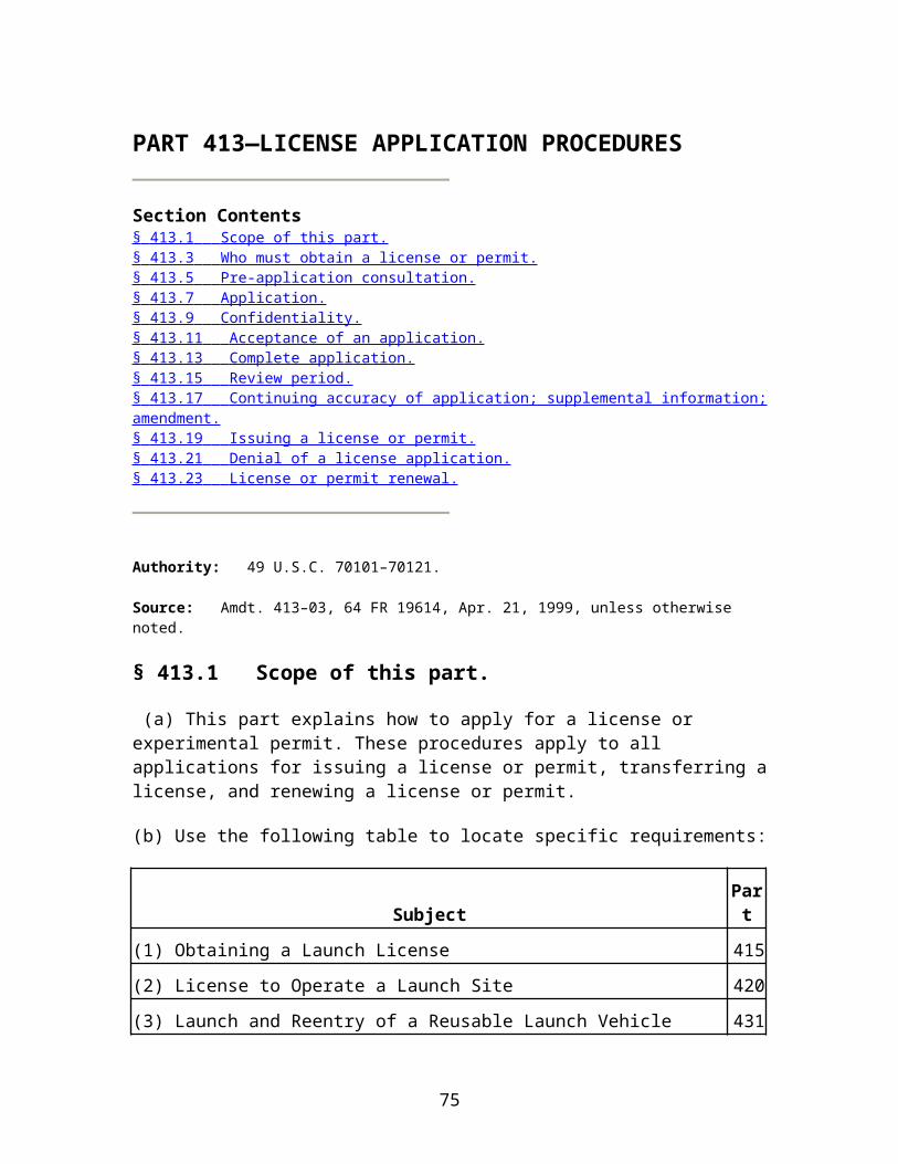
communication, both within the applicant's organization and between the applicant and any federal launch range providing launch services, shall be employed to ensure that personnel perform launch safety operations in accordance with range safety requirements and with plans and procedures required by this subpart. Approval authority shall be employed to ensure compliance with range safety requirements and with plans and procedures required by this subpart.
(b) Safety official. An applicant shall identify by name, title, and qualifications, a qualified safety official authorized to examine all aspects of the applicant's launch safety operations and to monitor independently personnel compliance with the applicant's safety policies and procedures. The safety official shall report directly to the person responsible for an applicant's licensed launches, who shall ensure that all of the safety official's concerns are addressed prior to launch.
§ 415.35 Acceptable flight risk.
(a) Flight risk through orbital insertion or impact. Acceptable flight risk through orbital insertion for an orbital launch vehicle, and through impact for a suborbital launch vehicle, is measured in terms of the expected average number of casualties (cc) to the collective members of the public exposed to debris hazards from any one launch. To obtain safety approval, an applicant must demonstrate that the risk level associated with debris from an applicant's proposed launch meets the public risk criteria of §417.107(b)(1) of this chapter for impacting inert and impacting explosive debris.
(b) Hazard identification and risk assessment. To demonstrate compliance with paragraph (a) of this section, an applicant must file an analysis that identifies hazards and assesses risks to public health and safety and safety of property associated with nominal and non-nominal flight of its proposed launch.
(c) Design. A launch vehicle must be designed to ensure that flight risks meet the criteria of paragraph (a) of this section. An applicant must identify and describe the following:
(1) Launch vehicle structure, including physical dimensions and weight;
(2) Hazardous and safety critical systems, including propulsion systems; and
(3) Drawings and schematics for each system identified under paragraph (c)(2) of this section.
(d) Operation. A launch vehicle must be operated in a manner that ensures that flight risks meet the criteria of paragraph (a) of this section. An applicant must identify all launch operations and procedures that must be performed to ensure acceptable flight risk.
[Doc. No. FAA–2000–7953, 71 FR 50531, Aug. 25, 2006]
§ 415.37 Flight readiness and communications plan.
75
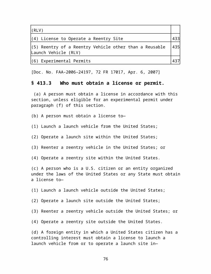
(a) Flight readiness requirements. An applicant must designate an individual responsible for flight readiness. The applicant must file the following procedures for verifying readiness for safe flight:
(1) Launch readiness review procedures involving the applicant's flight safety personnel and Federal launch range personnel involved in the launch, as required by §417.117(g) of this chapter.
(2) Procedures that ensure mission constraints, rules and abort procedures are listed and consolidated in a safety directive or notebook approved by licensee flight safety and Federal launch range personnel.
(3) Procedures that ensure currency and consistency of licensee and Federal launch range countdown checklists.
(4) Dress rehearsal procedures that—
(i) Ensure crew readiness under nominal and non-nominal flight conditions;
(ii) Contain criteria for determining whether to dispense with one or more dress rehearsals; and
(iii) Verify currency and consistency of licensee and Federal launch range countdown checklists.
(5) Procedures for ensuring the licensee's flight safety personnel adhere to the crew rest rules of §417.113(f) of this chapter.
(b) Communications plan requirements. An applicant must file a communications plan that meets §417.111(k) of this chapter, and that provides licensee and Federal launch range personnel communications procedures during countdown and flight.
(c) An applicant must file procedures that ensure that licensee and Federal launch range personnel receive a copy of the communications plan required by paragraph (b) of this section, and that the Federal launch range concurs in the communications plan.
[Doc. No. FAA–2000–7953, 71 FR 50531, Aug. 25, 2006]
§ 415.39 Safety at end of launch.
To obtain safety approval, an applicant must demonstrate compliance with §417.129 of this chapter, for any proposed launch of a launch vehicle with a stage or component that will reach Earth orbit.
[Doc. No. FAA–2000–7953, 71 FR 50531, Aug. 25, 2006]
76

§ 415.41 Accident investigation plan.
An applicant must file an accident investigation plan (AIP), that satisfies §417.111(g) of this chapter, and contains the applicant's procedures for reporting and responding to launch accidents, launch incidents, or other mishaps, as defined by §401.5 of this chapter.
[Doc. No. FAA–2000–7953, 71 FR 50531, Aug. 25, 2006]
§ 415.43 Denial of safety approval.
The FAA notifies an applicant, in writing, if it has denied safety approval for a license application. The notice states the reasons for the FAA's determination. The applicant may respond to the reasons for the determination and request reconsideration.
§§ 415.44-415.50 [Reserved]
Subpart D—Payload Review and Determination
§ 415.51 General.
The FAA reviews a payload proposed for launch to determine whether a license applicant or payload owner or operator has obtained all required licenses, authorization, and permits, unless the payload is exempt from review under §415.53 of this subpart. If not otherwise exempt, the FAA reviews a payload proposed for launch to determine whether its launch would jeopardize public health and safety, safety of property, U.S. national security or foreign policy interests, or international obligations of the United States. A payload determination is part of the licensing record on which the FAA's licensing determination is based. The safety requirements of subpart C and F of this part and of part 417 of this chapter apply to all payloads, whether or not the payload is otherwise exempt.
[Amdt. 415–03, 64 FR 19616, Apr. 21, 1999, as amended by Amdt. 415–4, 71 FR 50531, Aug. 25, 2006]
§ 415.53 Payloads not subject to review.
The FAA does not review payloads that are—
(a) Subject to regulation by the Federal Communications Commission (FCC) or the Department of Commerce, National Oceanic and Atmospheric Administration (NOAA); or
(b) Owned or operated by the U.S. Government.
§ 415.55 Classes of payloads.
77

The FAA may review and issue findings regarding a proposed class of payload, e.g., communications, remote sensing or navigation. However, each payload is subject to compliance monitoring by the FAA before launch to determine whether its launch would jeopardize public health and safety, safety of property, U.S. national security or foreign policy interests, or international obligations of the United States. The licensee is responsible for providing current information, in accordance with §415.79(a), regarding a payload proposed for launch not later than 60 days before a scheduled launch.
§ 415.57 Payload review.
(a) Timing. A payload review may be conducted as part of a license application review or may be requested by a payload owner or operator in advance of or apart from a license application.
(b) Interagency consultation. The FAA consults with other agencies to determine whether launch of a proposed payload or payload class would present any issues affecting public health and safety, safety of property, U.S. national security or foreign policy interests, or international obligations of the United States.
(1) The FAA consults with the Department of Defense to determine whether launch of a proposed payload or payload class would present any issues affecting U.S. national security.
(2) The FAA consults with the Department of State to determine whether launch of a proposed payload or payload class would present any issues affecting U.S. foreign policy interests or international obligations.
(3) The FAA consults with other federal agencies, including the National Aeronautics and Space Administration, authorized to address issues identified under paragraph (b) of this section associated with an applicant's launch proposal.
(c) The FAA advises a person requesting a payload determination, in writing, of any issue raised during a payload review that would impede issuance of a license to launch that payload or payload class. The person requesting payload review may respond, in writing, or revise its application.
§ 415.59 Information requirements for payload review.
(a) A person requesting review of a particular payload or payload class shall identify the following:
(1) Payload name;
(2) Payload class;
(3) Physical dimensions and weight of the payload;
78

(4) Payload owner and operator, if different from the person requesting payload review;
(5) Orbital parameters for parking, transfer and final orbits;
(6) Hazardous materials, as defined in §401.5 of this chapter, and radioactive materials, and the amounts of each;
(7) Intended payload operations during the life of the payload; and
(8) Delivery point in flight at which the payload will no longer be under the licensee's control.
(b) [Reserved]
§ 415.61 Issuance of payload determination.
(a) The FAA issues a favorable payload determination unless it determines that launch of the proposed payload would jeopardize public health and safety, safety of property, U.S. national security or foreign policy interests, or international obligations of the United States. The FAA advises any person who has requested a payload review of its determination, in writing. The notice states the reasons for the determination in the event of an unfavorable determination.
(b) Any person issued an unfavorable payload determination may respond to the reasons for the determination and request reconsideration.
§ 415.63 Incorporation of payload determination in license application.
A favorable payload determination issued for a payload or class of payload may be included by a license applicant as part of its application. However, any change in information provided under section 415.59 of this subpart must be reported in accordance with section 413.17 of this chapter. The FAA determines whether a favorable payload determination remains valid in light of reported changes and may conduct an additional payload review.
§§ 415.64-415.70 [Reserved]
Subpart E [Reserved]
Subpart F—Safety Review and Approval for Launch of an Expendable Launch Vehicle From a Non-Federal Launch Site
Source: Docket No. FAA–2000–7953, 71 FR 50532, Aug. 25, 2006, unless otherwise noted.
§§ 415.91--415.100 [Reserved]
79
§ 415.101 Scope and applicability.
(a) This subpart F contains requirements that an applicant must meet to obtain a safety approval when applying for a license to launch an expendable launch vehicle from a non-Federal launch site. This subpart also contains administrative requirements for a safety review, such as when and how an applicant files the required information, and the requirements for the form and content of each submission.
(b) The requirements of this subpart apply to both orbital and suborbital expendable launch vehicles.
(c) An applicant must demonstrate, through the material filed with the FAA, its ability to comply with the requirements of part 417 of this chapter. To facilitate production of the information required by this subpart, an applicant should become familiar with the requirements of part 417 of this chapter.
(d) For a launch from an exclusive use launch site, where there is no licensed launch site operator, a launch operator must satisfy the requirements of this part and the public safety application requirements of part 420 of this chapter.
§ 415.102 Definitions.
For the purposes of this subpart, the definitions of §§417.3 and 401.5 of this chapter apply.
§ 415.103 General.
(a) The FAA conducts a safety review to determine whether an applicant is capable of conducting launch processing and flight without jeopardizing public health and safety and safety of property. The FAA issues a safety approval to a license applicant if the applicant satisfies the requirements of this subpart and demonstrates that it will meet the safety responsibilities and requirements of part 417 of this chapter.
(b) The FAA advises an applicant, in writing, of any issue raised during a safety review that would impede issuance of a safety approval. The applicant may respond, in writing, or amend its license application as required by §413.17 of this chapter.
(c) An applicant must make available to the FAA upon request a copy of any information incorporated into a license application by reference.
(d) A safety approval is part of the licensing record on which the FAA bases its licensing determination.
§ 415.105 Pre-application consultation.
80

(a) An applicant must participate in a pre-application consultation meeting, as required by §413.5 of this chapter, prior to an applicant's preparation of the initial flight safety analysis required by §415.115.
(b) At a pre-application consultation meeting, an applicant must provide as complete a description of the planned launch or series of launches as available at the time. An applicant must provide the FAA the following information:
(1) Launch vehicle. Description of:
(i) Launch vehicle;
(ii) Any flight termination system; and
(iii) All hazards associated with the launch vehicle and any payload, including the type and amounts of all propellants, explosives, toxic materials and any radionuclides.
(2) Proposed mission. (i) For an applicant applying for a launch specific license under §415.3(a), the apogee, perigee, and inclination of any orbital objects and each impact location of any stage or other component.
(ii) For an applicant applying for a launch operator license under §415.3(b), the planned range of trajectories and flight azimuths, and the range of apogees, perigees, and inclinations of any orbital objects and each impact location of any stage or other component.
(3) Potential launch site. (i) Name and location of the proposed launch site, including latitude and longitude of the proposed launch point;
(ii) Identity of any launch site operator of that site; and
(iii) Identification of any facilities at the launch site that will be used for launch processing and flight.
§ 415.107 Safety review document.
(a) An applicant must file a safety review document that contains all the information required by §§415.109—415.133. An applicant must file the information for a safety review document as required by the outline in appendix B of this part. An applicant must file a sufficiently complete safety review document, except for the ground safety analysis report, no later than six months before the applicant brings any launch vehicle to the proposed launch site.
(b) A launch operator's safety review document must:
(1) Contain a glossary of unique terms and acronyms used in alphabetical order;
81

(2) Contain a listing of all referenced standards, codes, and publications;
(3) Be logically organized, with a clear and consistent page numbering system and must identify cross-referenced topics;
(4) Use equations and mathematical relationships derived from or referenced to a recognized standard or text, and must define all algebraic parameters;
(5) Include the units of all numerical values provided; and
(6) Include a legend or key that identifies all symbols used for any schematic diagrams.
(c) An applicant's safety review document may include sections not required by appendix B of this part. An applicant must identify each added section by using the word “added” in front of the title of the section. In the first paragraph of the section, an applicant must explain any addition to the outline in appendix B of this part.
(d) If a safety review document section required by appendix B of this part does not apply to an applicant's proposed launch, an applicant must identify the sections in the application by the words “not applicable” preceding the title of the section. In the first paragraph of the section, an applicant must describe and justify why the section does not apply.
(e) An applicant may reference documentation previously filed with the FAA.
§ 415.109 Launch description.
An applicant's safety review document must contain the following information:
(a) Launch site description. An applicant must identify the proposed launch site and include the following:
(1) Boundaries of the launch site;
(2) Launch point location, including latitude and longitude;
(3) Identity of any launch site operator of that proposed site; and
(4) Identification of any facilities at the launch site that will be used for launch processing and flight.
(b) Launch vehicle description. An applicant must provide the following:
(1) A written description of the launch vehicle. The description must include a table specifying the type and quantities of all hazardous materials on the launch vehicle and must include propellants, explosives, and toxic materials; and
82
(2) A drawing of the launch vehicle that identifies:
(i) Each stage, including strap-on motors;
(ii) Physical dimensions and weight;
(iii) Location of all safety critical systems, including any flight termination hardware, tracking aids, or telemetry systems;
(iv) Location of all major launch vehicle control systems, propulsion systems, pressure vessels, and any other hardware that contains potential hazardous energy or hazardous material; and
(v) For an unguided suborbital launch vehicle, the location of the rocket's center of pressure in relation to its center of gravity for the entire flight profile.
(c) Payload description. An applicant must include or reference documentation previously filed with the FAA that contains the payload information required by §415.59 for any payload or class of payload.
(d) Trajectory. An applicant must provide two drawings depicting trajectory information. An applicant must file additional trajectory information as part of the flight safety analysis data required by §415.115.
(1) One drawing must depict the proposed nominal flight profile with downrange depicted on the abscissa and altitude depicted on the ordinate axis. The nominal flight profile must be labeled to show each planned staging event and its time after liftoff from launch through orbital insertion or final impact; and
(2) The second drawing must depict instantaneous impact point ground traces for each of the nominal trajectory, the three-sigma left lateral trajectory and the three-sigma right lateral trajectory determined under §417.207 of this chapter. The trajectories must be depicted on a latitude/longitude grid, and the grid must include the outlines of any continents and islands.
(e) Staging events. An applicant must provide a table of nominal and ± three-sigma times for each major staging event and must describe each event, including the predicted impact point and dispersion of each spent stage.
(f) Vehicle performance graphs. An applicant must provide graphs of the nominal and ± three-sigma values as a function of time after liftoff for the following launch vehicle performance parameters: thrust, altitude, velocity, instantaneous impact point arc-range measured from the launch point, and present position arc-range measured from the launch point.
§ 415.111 Launch operator organization.
83

An applicant's safety review document must contain organizational charts and a description that shows that the launch operator's organization satisfies the requirements of §417.103 of this chapter. An applicant's safety review document must also identify all persons with whom the applicant has contracted to provide safety-related goods or services for the launch of the launch vehicle.
§ 415.113 Launch personnel certification program.
(a) A safety review document must describe how the applicant will satisfy the personnel certification program requirements of §417.105 of this chapter and identify by position those individuals who implement the program.
(b) An applicant's safety review document must contain a copy of its documentation that demonstrates how the launch operator implements the personnel certification program.
(c) An applicant's safety review document must contain a table listing each hazardous operation or safety critical task that certified personnel must perform. For each task, the table must identify by position the individual who reviews personnel qualifications and certifies personnel for performing the task.
§ 415.115 Flight safety.
(a) Flight safety analysis. An applicant's safety review document must describe each analysis method employed to meet the flight safety analysis requirements of part 417, subpart C, of this chapter. An applicant's safety review document must demonstrate how each analysis method satisfies the flight safety analysis requirements of part 417, subpart C, of this chapter. An applicant's safety review document must contain analysis products and other data that demonstrate the applicant's ability to meet the public risk criteria of §417.107 of this chapter and to establish launch safety rules as required by §417.113 of this chapter. An applicant's flight safety analysis must satisfy the following requirements:
(1) An applicant must file the proposed flight safety analysis methodology and the preliminary flight safety analysis products no later than 18 months for any orbital or guided suborbital launch vehicle, and nine months for any unguided suborbital launch vehicle, prior to bringing any launch vehicle to the proposed launch site.
(2) For a launch operator license, an applicant must file flight safety analysis products that account for the range of launch vehicles and flight trajectories applied for, or the worst case vehicle and trajectory under which flight will be attempted, no later than 6 months before the applicant brings any launch vehicle to the proposed launch site. For a launch specific license, an applicant must file flight safety analysis products that account for the actual flight conditions, no later than 6 months before the applicant brings any launch vehicle to the proposed launch site.
(3) The flight safety analysis performed by an applicant must be completed as required by subpart C of part 417 of this chapter. An applicant may identify those portions of the
84
analysis that it expects to refine as the first proposed flight date approaches. An applicant must identify any analysis product subject to change, describe what needs to be done to finalize the product, and identify when before flight it will be finalized. If a license allows more than one launch, an applicant must demonstrate the applicability of the analysis methods to each of the proposed launches and identify any expected differences in the flight safety analysis methods among the proposed launches. Once licensed, a launch operator must perform a flight safety analysis for each launch using final launch vehicle performance and other data as required by subpart C of part 417 of this chapter and using the analysis methods approved by the FAA through the licensing process.
(b) Radionuclides. An applicant's safety review document must identify the type and quantity of any radionuclide on a launch vehicle or payload. For each radionuclide, an applicant must include a reference list of all documentation addressing the safety of its intended use and describe all approvals by the Nuclear Regulatory Commission for launch processing. An applicant must provide radionuclide information to the FAA at the pre-application consultation as required by §415.105. The FAA will evaluate launch of any radionuclide on a case-by-case basis, and issue an approval if the FAA finds that the launch is consistent with public health and safety.
(c) Flight safety plan. An applicant's safety review document must contain a flight safety plan that satisfies §417.111(b) of this chapter. The plan need not be restricted to public safety related issues and may combine other flight safety issues as well, such as employee safety, so as to be all-inclusive.
(d) Natural and triggered lightning . For any orbital or guided suborbital expendable launch vehicle, an applicant must demonstrate that it will satisfy the flight commit criteria of §417.113(c) of this chapter and appendix G of part 417 of this chapter for natural and triggered lightning. If an applicant's safety review document states that any flight commit criterion that is otherwise required by appendix G of part 417 of this chapter does not apply to a proposed launch or series of launches, the applicant's safety review document must demonstrate that the criterion does not apply.
§ 415.117 Ground safety.
(a) General. An applicant's safety review document must include a ground safety analysis report, and a ground safety plan for its launch processing and post-flight operations as required by this section, §417.109 of this chapter, and subpart E of part 417 of this chapter when launching from a launch point in the United States. Launch processing and post-launch operations at a launch point outside the United States may be subject to the requirements of the governing jurisdiction.
(b) Ground safety analysis. A ground safety analysis must review each system and operation used in launch processing and post-flight operations as required by §417.109 of this chapter, and subpart E of part 417 of this chapter.
85

(1) An applicant must file an initial ground safety analysis report no later than 12 months for any orbital or guided suborbital launch vehicle, and nine months for an unguided suborbital launch vehicle, before the applicant brings any launch vehicle to the proposed launch site. An initial ground safety analysis report must be in a proposed final or near final form and identify any incomplete items. An applicant must document any incomplete items and track them to completion. An applicant must resolve any FAA comments on the initial report and file a complete ground safety analysis report, no later than two months before the applicant brings any launch vehicle to the proposed launch site. Furthermore, an applicant must keep its ground safety analysis report current. Any late developing change to a ground safety analysis report must be coordinated with the FAA as an application amendment as required by §413.17 of this chapter as soon as the applicant identifies the need for a change.
(2) An applicant must file a ground safety analysis report that satisfies the ground safety analysis requirements of §417.109 of this chapter, and subpart E of part 417 of this chapter.
(3) The person designated under §417.103(b)(1) of this chapter and the person designated under §417.103(b)(2) of this chapter must approve and sign the ground safety analysis report.
(c) Ground safety plan. An applicant's safety review document must contain a ground safety plan that satisfies §417.111(c) of this chapter. The applicant must file this plan with the FAA no later than six months prior to bringing the launch vehicle to the proposed launch site. This ground safety plan must describe implementation of the hazard controls identified by an applicant's ground safety analysis and implementation of the ground safety requirements of subpart E of part 417 of this chapter. A ground safety plan must address all public safety related issues and may include other ground safety issues if an applicant intends it to have a broader scope.
§ 415.119 Launch plans.
An applicant's safety review document must contain the plans required by §417.111 of this chapter, except for the countdown plan of §417.111(l) of this chapter. An applicant's launch plans do not have to be separate documents, and may be part of other applicant documentation. An applicant must incorporate each launch safety rule established under §417.113 of this chapter into a related launch safety plan.
§ 415.121 Launch schedule.
An applicant's safety review document must contain a generic launch processing schedule that identifies each review, rehearsal, and safety critical preflight operation to be conducted as required by §§417.117, 417.119, and 417.121 of this chapter. The launch schedule must also identify day of flight activities. The launch processing schedule must show each of these activities referenced to liftoff, such as liftoff minus three days.
86

§ 415.123 Computing systems and software.
(a) An applicant's safety review document must describe all computing systems and software that perform a safety-critical computer system function for any operation performed during launch processing or flight that could have a hazardous effect on the public as required by §417.123 of this chapter.
(b) An applicant's safety review document must list and describe all safety-critical computer system functions involved in a proposed launch, including associated hardware and software interfaces. For each system with a safety-critical computer system function, an applicant's safety review document must:
(1) Describe all safety-critical computer system functions, including each safety-critical interface with any other system;
(2) Describe all systems, including all hardware and software, and the layout of each operator console and display;
(3) Provide flow charts or diagrams that show all hardware data busses, hardware interfaces, software interfaces, data flow, and power systems, and all operations of each safety-critical computer system function;
(4) Provide all logic diagrams and software designs;
(5) List all operator user manuals and documentation by title and date;
(6) Describe the computing system and software system safety process as required by §417.123(a).
(7) Provide all results of computing system and software hazard analyses as required by §417.123(c).
(8) Provide all plans and results of computing systems and software validation and verification as required by §417.123(d).
(9) Provide all plans for software development as required by §417.123(e).
§ 415.125 Unique safety policies, requirements and practices.
An applicant's safety review document must identify any public safety-related policy, requirement, or practice that is unique to the proposed launch, or series of launches, as required by §417.127 of this chapter. An applicant's safety review document must describe how each unique safety policy, requirement, or practice ensures the safety of the public.
§ 415.127 Flight safety system design and operation data.
87

(a) General. This part applies to an applicant launching an orbital or guided sub-orbital expendable launch vehicle that uses a flight safety system to protect public safety as required by §417.107(a) of this chapter. An applicant's safety review document must contain the flight safety system data identified by this section. The applicant must file all data required by this section no later than 18 months before bringing any launch vehicle to a proposed launch site.
(b) Flight safety system description. A safety review document must describe an applicant's flight safety system and its operation. Part 417, subpart D of this chapter and appendices D, E, and F of part 417 of this chapter contain the flight safety system and subsystems design and operational requirements.
(c) Flight safety system diagram. An applicant's safety review document must contain a block diagram that identifies all flight safety system subsystems. The diagram must include the following subsystems defined in part 417, subpart D of this chapter: flight termination system; command control system; tracking; telemetry; communications; flight safety data processing, display, and recording system; and flight safety official console.
(d) Subsystem design information. An applicant's safety review document must contain all of the following data that applies to each subsystem identified in the block diagram required by paragraph (c) of this section:
(1) Subsystem description. A physical description of each subsystem and its components, its operation, and interfaces with other systems or subsystems.
(2) Subsystem diagram. A physical and functional diagram of each subsystem, including interfaces with other systems and subsystems.
(3) Component location. Drawings showing the location of all subsystem components, and the details of the mounting arrangements, as installed on the vehicle, and at the launch site.
(4) Electronic components. A physical description of each subsystem electronic component, including operating parameters and functions at the system and piece-part level. An applicant must also provide the name of the manufacturer and any model number of each component and identify whether the component is custom designed and built or off-the-shelf-equipment.
(5) Mechanical components. An illustrated parts breakdown of all mechanically operated components for each subsystem, including the name of the manufacturer and any model number.
(6) Subsystem compatibility. A demonstration of the compatibility of the onboard launch vehicle flight termination system with the command control system.
88
(7) Flight termination system component storage, operating, and service life. A listing of all flight termination system components that have a critical storage, operating, or service life and a summary of the applicant's procedures for ensuring that each component does not exceed its storage, operating, or service life before flight.
(8) Flight termination system element location. For a flight termination system, a description of where each subsystem element is located, where cables are routed, and identification of mounting attach points and access points.
(9) Flight termination system electrical connectors and connections and wiring diagrams and schematics . For a flight termination system, a description of all subsystem electrical connectors and connections, and any electrical isolation. The safety review document must also contain flight termination system wiring diagrams and schematics and identify the test points used for integrated testing and checkout.
(10) Flight termination system batteries. A description of each flight termination system battery and cell, the name of the battery or cell manufacturer, and any model numbers.
(11) Controls and displays. For a flight safety official console, a description of all controls, displays, and charts depicting how real time vehicle data and flight safety limits are displayed. The description must identify the scales used for displays and charts.
(e) System analyses. An applicant must perform the reliability and other system analyses for a flight termination system and command control system of §417.309 of this chapter. An applicant's safety review document must contain the results of each analysis.
(f) Environmental design. An applicant must determine the flight termination system maximum predicted environment levels required by section D417.7 of appendix D of part 417 of this chapter, and the design environments and design margins of section D417.3 of appendix D of part 417 of this chapter. An applicant's safety review document must summarize the analyses and measurements used to derive the maximum predicted environment levels. The safety review document must contain a matrix that identifies the maximum predicted environment levels and the design environments.
(g) Flight safety system compliance matrix. An applicant's safety review document must contain a compliance matrix of the function, reliability, system, subsystem, and component requirements of part 417 of this chapter and appendix D of part 417 of this chapter. This matrix must identify each requirement and indicate compliance as follows:
(1) “Yes” if the applicant's system meets the requirement of part 417 of this chapter. The matrix must reference documentation that demonstrates compliance;
(2) “Not applicable” if the applicant's system design and operational environment are such that the requirement does not apply. For each such case, the applicant must demonstrate, in accordance with section 406.3(b), the non-applicability of that requirement as an attachment to the matrix; or
89
(3) “Equivalent level of safety” in each case where the applicant proposes to show that its system provides an equivalent level of safety through some means other than that required by part 417 of this chapter. For each such case, an applicant must clearly and convincingly demonstrate, as required by §406.3(b), through a technical rationale within the matrix, or as an attachment, that the proposed alternative provides a level of safety equivalent to satisfying the requirement that it would replace.
(h) Flight termination system installation procedures. An applicant's safety review document must contain a list of the flight termination system installation procedures and a synopsis of the procedures that demonstrates how each of those procedures meet the requirements of section D417.15 of appendix D of part 417 of this chapter. The list must reference each procedure by title, any document number, and date.
(i) Tracking validation procedures. An applicant's safety review document must contain the procedures identified by §417.121(h) of this chapter for validating the accuracy of the launch vehicle tracking data supplied to the flight safety crew.
§ 415.129 Flight safety system test data.
(a) General. An applicant's safety review document must contain the flight safety system test data required by this section for the launch of an orbital and guided suborbital expendable launch vehicle that uses a flight safety system to protect public safety as required by §417.107(a) of this chapter. This section applies to all testing required by part 417, subpart D of this chapter and its appendices, including qualification, acceptance, age surveillance, and preflight testing of a flight safety system and its subsystems and individual components. An applicant must file all required test data, no later than 12 months before the applicant brings any launch vehicle to the proposed launch site. An applicant may file test data earlier to allow greater time for addressing issues that the FAA may identify to avoid possible impact on the proposed launch date. Flight safety system testing need not be completed before the FAA issues a launch license. Prior to flight, a licensee must successfully complete all required flight safety system testing and file the completed test reports or the test report summaries required by §417.305(d) of this chapter and section E417.1(i) of appendix E of part 417 of this chapter.
(b) Testing compliance matrix. An applicant's safety review document must contain a compliance matrix of all the flight safety system, subsystem, and component testing requirements of part 417 of this chapter and appendix E to part 417 of this chapter. This matrix must identify each test requirement and indicate compliance as follows:
(1) “Yes” if the applicant performs the system or component testing required by part 417 of this chapter. The matrix must reference documentation that demonstrates compliance;
(2) “Not applicable” if the applicant's system design and operational environment are such that the test requirement does not apply. For each such case, an applicant must demonstrate, as required by §406.3(b), of the non-applicability of that requirement as an attachment to the matrix;
90

(3) “Similarity” if the test requirement applies to a component whose design is similar to a previously qualified component. For each such case, an applicant must demonstrate similarity by performing the analysis required by appendix E of part 417 of this chapter. The matrix, or an attachment, must contain the results of each analysis; or
(4) “Equivalent level of safety” in each case where the applicant proposes to show that its test program provides an equivalent level of safety through some means other than that required by part 417 of this chapter. For each such case, an applicant must clearly and convincingly demonstrate through a technical rationale, within the matrix or as an attachment, that the alternative provides a level of safety equivalent to satisfying the requirement that it replaces, as required by §406.3(c).
(c) Test program overview and schedule. A safety review document must contain a summary of the applicant's flight safety system test program that identifies the location of the testing and the personnel who ensure the validity of the results. A safety review document must contain a schedule for successfully completing each test before flight. The applicant must reference the schedule to the time of liftoff for the first proposed flight attempt.
(d) Flight safety system test plans and procedures. An applicant's safety review document must contain test plans that satisfy the flight safety system testing requirements of subpart D of part 417 of this chapter and appendix E of part 417 of this chapter. An applicant's safety review document must contain a list of all flight termination system test procedures and a synopsis of the procedures that demonstrates how they meet the test requirements of part 417 of this chapter. The list must reference each procedure by title, any document number, and date.
(e) Test reports. An applicant's safety review document must contain either the test reports, or a summary of the test report which captures the overall test results, including all test discrepancies and their resolution, prepared as required by §417.305(d) of this chapter and section E417.1(i) of appendix E of part 417 of this chapter, for each flight safety system test completed at the time of license application. An applicant must file any remaining test reports or summaries before flight as required by §417.305(d) and section E417.1(i) of appendix E of part 417 of this chapter. Upon request, the launch operator must file the complete test report with the FAA for review, if the launch operator previously filed test report summaries with the FAA.
(f) Reuse of flight termination system components. An applicant's safety review document must contain a reuse qualification test, refurbishment plan, and acceptance test plan for the use of any flight termination system component on more than one flight. This test plan must define the applicant's process for demonstrating that the component can satisfy all its performance specifications when subjected to the qualification test environmental levels plus the total number of exposures to the maximum expected environmental levels for each of the flights to be flown.
§ 415.131 Flight safety system crew data.
91

(a) An applicant's safety review document must identify each flight safety system crew position and the role of that crewmember during launch processing and flight of a launch vehicle.
(b) An applicant's safety review document must describe the certification program for flight safety system crewmembers established to ensure compliance with §§417.105 and 417.311 of this chapter.
§ 415.133 Safety at end of launch.
An applicant must demonstrate compliance with §417.129 of this chapter, for any proposed launch of a launch vehicle with a stage or component that will reach Earth orbit.
§ 415.135 Denial of safety approval.
The FAA notifies an applicant, in writing, if it has denied safety approval for a license application. The notice states the reasons for the FAA's determination. The applicant may respond to the reasons for the determination and request reconsideration.
§§ 415.136--415.200 [Reserved]
Subpart G—Environmental Review
§ 415.201 General.
An applicant shall provide the FAA with information for the FAA to analyze the environmental impacts associated with a proposed launch. The information provided by an applicant must be sufficient to enable the FAA to comply with the requirements of the National Environment Policy Act, 42 U.S.C. 4321 et seq. (NEPA), the Council on Environmental Quality Regulations for Implementing the Procedural Provisions of NEPA, 40 CFR parts 1500–1508, and the FAA's Procedures for Considering Environmental Impacts, FAA Order 1050.1D.
[Amdt. 415–03, 64 FR 19616, Apr. 21, 1999. Redesignated by Amdt. 415–4, 71 FR 50532, Aug. 25, 2006]
§ 415.203 Environmental information.
An applicant shall submit environmental information concerning:
(a) A proposed launch site not covered by existing environmental documentation;
(b) A proposed launch vehicle with characteristics falling measurably outside the parameters of existing environmental documentation;
92
(c) A proposed launch from an established launch site involving a vehicle with characteristics falling measurably outside the parameters of any existing environmental impact statement that applies to that site;
(d) A proposed payload that may have significant environmental impacts in the event of a mishap; and
(e) Other factors as determined by the FAA.
[Amdt. 415–03, 64 FR 19616, Apr. 21, 1999. Redesignated by Amdt. 415–4, 71 FR 50532, Aug. 25, 2006]
§§ 415.204--415.400 [Reserved]
93
Appendix A to Part 415—FAA/USSPACECOM Launch Notification Form
94

95
Appendix B of Part 415—Safety Review Document Outline
This appendix contains the format and numbering scheme for a safety review document to be filed as part of an application for a launch license as required by subpart F of part 415. The applicable sections of parts 413, 415, and 417 of this chapter are referenced in the outline below.
Safety Review Document
1.0 Launch Description (§415.109)
1.1 Launch Site Description
1.2 Launch Vehicle Description
1.3 Payload Description
1.4 Trajectory
1.5 Staging Events
1.6 Vehicle Performance Graphs
2.0 Launch Operator Organization (§415.111)
2.1 Launch Operator Organization (§415.111 and §417.103 of this chapter)
2.1.1 Organization Summary
2.1.3 Organization Charts
2.1.4 Office Descriptions and Safety Functions
3.0 Launch Personnel Certification Program (§415.113 and §417.105 of this chapter)
3.1 Program Summary
3.2 Program Implementation Document(s)
3.3 Table of Safety Critical Tasks Performed by Certified Personnel
4.0 Flight Safety (§415.115)
4.1 Initial Flight Safety Analysis
96

4.1.1 Flight Safety Sub-Analyses, Methods, and Assumptions
4.1.2 Sample Calculation and Products
4.1.3 Launch Specific Updates and Final Flight Safety Analysis Data
4.2 Radionuclide Data (where applicable)
4.3 Flight Safety Plan
4.3.1 Flight Safety Personnel
4.3.2 Flight Safety Rules
4.3.3 Flight Safety System Summary and Preflight Tests
4.3.4 Trajectory and Debris Dispersion Data
4.3.5 Flight Hazard Areas and Safety Clear Zones
4.3.6 Support Systems and Services
4.3.7 Flight Safety Operations
4.3.8 Unguided Suborbital Launch Vehicles (where applicable)
5.0 Ground Safety (§415.117)
5.1 Ground Safety Analysis Report
5.2 Ground Safety Plan
6.0 Launch Plans (§415.119 and §417.111 of this chapter)
6.1 Launch Support Equipment and Instrumentation Plan
6.2 Configuration Management and Control Plan
6.3 Frequency Management Plan
6.4 Flight Termination System Electronic Piece Parts Program Plan
6.5 Accident Investigation Plan
6.6 Local Agreements and Public Coordination Plan
97
6.7 Hazard Area Surveillance and Clearance Plan
6.8 Communications Plan
7.0 Launch Schedule (§415.121)
7.1 Launch Processing Schedule
8.0 Computing Systems and Software (§415.123)
8.1 Hardware and Software Descriptions
8.2 Flow Charts and Diagrams
8.3 Logic Diagrams and Software Design Descriptions
8.4 Operator User Manuals and Documentation
8.5 Software Hazard Analyses
8.6 Software Test Plans, Test Procedures, and Test Results
8.7 Software Development Plan
9.0 Unique Safety Policies, Requirements and Practices (§415.125)
10.0 Flight Safety System Design and Operation Data (§415.127)
10.1 Flight Safety System Description
10.2 Flight Safety System Diagram
10.3 Flight Safety System Subsystem Design Information
10.4 Flight Safety System Analyses
10.5 Flight Termination System Environmental Design
10.6 Flight Safety System Compliance Matrix
10.7 Flight Termination System Installation Procedures
10.8 Tracking System Validation Procedures
11.0 Flight Safety System Test Data (§415.129)
98

11.1 Testing Compliance Matrix
11.2 Test Program Overview and Schedule
11.3 Flight Safety System Test Plans and Procedures
11.4 Test Reports
11.5 Reuse of Flight Termination System Components
12.0 Flight Safety System Crew Data (§415.131)
12.1 Position Descriptions
12.2 Certification and Training Program Description
13.0 Safety at End of Launch (§415.133)
[Docket No. FAA–2000–7953, 71 FR 50536, Aug. 25, 2006]
99

PART 417—LAUNCH SAFETY
Section Contents
Subpart A—General and License Terms and Conditions
§ 417.1 General information. § 417.3 Definitions and acronyms. § 417.5 [Reserved] § 417.7 Public safety responsibility. § 417.9 Launch site responsibility. § 417.11 Continuing accuracy of license application; application for modification of license. § 417.13 Agreement with Federal launch range. § 417.15 Records. § 417.17 Launch reporting requirements and launch specific updates. § 417.19 Registration of space objects. § 417.21 Financial responsibility requirements. § 417.23 Compliance monitoring. § 417.25 Post launch report. §§ 417.26--417.100 [Reserved]
Subpart B—Launch Safety Responsibilities
§ 417.101 Scope. § 417.103 Safety organization. § 417.105 Launch personnel qualifications and certification. § 417.107 Flight safety. § 417.109 Ground safety. § 417.111 Launch plans. § 417.113 Launch safety rules. § 417.115 Tests. § 417.117 Reviews. § 417.119 Rehearsals. § 417.121 Safety critical preflight operations. § 417.123 Computing systems and software. § 417.125 Launch of an unguided suborbital launch vehicle. § 417.127 Unique safety policies, requirements and practices. § 417.129 Safety at end of launch. §§ 417.130--417.200 [Reserved]
Subpart C—Flight Safety Analysis
§ 417.201 Scope and applicability. § 417.203 Compliance. § 417.205 General. § 417.207 Trajectory analysis. § 417.209 Malfunction turn analysis. § 417.211 Debris analysis. § 417.213 Flight safety limits analysis. § 417.215 Straight-up time analysis. § 417.217 Overflight gate analysis.
100

§ 417.218 Hold-and-resume gate analysis. § 417.219 Data loss flight time and planned safe flight state analyses. § 417.221 Time delay analysis. § 417.223 Flight hazard area analysis. § 417.224 Probability of failure analysis. § 417.225 Debris risk analysis. § 417.227 Toxic release hazard analysis. § 417.229 Far-field overpressure blast effects analysis. § 417.231 Collision avoidance analysis. § 417.233 Analysis for an unguided suborbital launch vehicle flown with a wind weighting safety system.
Subpart D—Flight Safety System
§ 417.301 General. § 417.303 Command control system requirements. § 417.305 Command control system testing. § 417.307 Support systems. § 417.309 Flight safety system analysis. § 417.311 Flight safety crew roles and qualifications.
Subpart E—Ground Safety
§ 417.401 Scope. § 417.402 Compliance. § 417.403 General. § 417.405 Ground safety analysis. § 417.407 Hazard control implementation. § 417.409 System hazard controls. § 417.411 Safety clear zones for hazardous operations. § 417.413 Hazard areas. § 417.415 Post-launch and post-flight-attempt hazard controls. § 417.417 Propellants and explosives. Appendix A to Part 417—Flight Safety Analysis Methodologies and Products for a Launch Vehicle Flown With a Flight Safety SystemAppendix B to Part 417—Flight Hazard Area Analysis for Aircraft and Ship ProtectionAppendix C to Part 417—Flight Safety Analysis Methodologies and Products for an Unguided Suborbital Launch Vehicle Flown With a Wind Weighting Safety SystemAppendix D to Part 417—Flight Termination Systems, Components, Installation, and MonitoringAppendix E to Part 417—Flight Termination System Testing and AnalysisAppendix F to Part 417 [Reserved]Appendix G to Part 417—Natural and Triggered Lightning Flight Commit CriteriaAppendix H to Part 417 [Reserved]Appendix I to Part 417—Methodologies for Toxic Release Hazard Analysis and Operational ProceduresAppendix J to Part 417—Ground Safety Analysis Report
Authority: 49 U.S.C. 70101–70121.
Source: Docket No. FAA–2000–7953, 71 FR 50537, Aug. 25, 2006, unless otherwise noted.
Subpart A—General and License Terms and Conditions
101

§ 417.1 General information.
(a) Scope. This part sets forth—
(1) The responsibilities of a launch operator conducting a licensed launch of an expendable launch vehicle; and
(2) The requirements for maintaining a launch license obtained under part 415 of this chapter. Parts 413 and 415 of this chapter contain requirements for preparing a license application to conduct a launch, including information reviewed by the FAA to conduct a policy, safety, payload, and environmental review., and a payload determination.
(b) Applicability. (1) The administrative requirements for filing material with the FAA in subpart A of this part apply to all licensed launches from a Federal launch range or a non-Federal launch site, except where noted.
(2) The safety requirements of subparts B through E of this part apply to all licensed launches of expendable launch vehicles. See paragraphs (d) and (e) of this section for exceptions to this provision.
(c) “Meets intent” certification. For a licensed launch from a Federal launch range, a launch operator need not demonstrate to the FAA that an alternative means of satisfying a requirement of this part provides an equivalent level of safety for a launch if written evidence demonstrates that a Federal launch range has, by the effective date of this part, granted a “meets intent certification,” including through “tailoring,” that applies to the requirement and that launch. See paragraph (f) of this section for exceptions to this provision. Written evidence includes:
(1) Range flight plan approval,
(2) Missile system pre-launch safety package,
(3) Preliminary and final flight data packages,
(4) A tailored version of EWR 127–1,
(5) Range email to the FAA stating that the MIC was approved, or
(6) Operation approval.
(d) Waiver. For a licensed launch from a Federal launch range, a requirement of this part does not apply to a launch if written evidence demonstrates that a Federal launch range has, by the effective date of this part, granted a waiver that allows noncompliance with the requirement for that launch. See paragraph (f) of this section for exceptions to this provision. Written evidence includes:
102

(1) Range flight plan approval,
(2) Missile system pre-launch safety package,
(3) Preliminary and final flight data packages,
(4) A tailored version of EWR 127–1,
(5) Range email to the FAA stating that the waiver was approved, or
(6) Operation approval.
(e) Grandfathering. For a licensed launch from a Federal launch range, a requirement of this part does not apply to the launch if the Federal launch range's grandfathering criteria allow noncompliance with the requirement for that launch. See paragraph (f) of this section for exceptions to this provision.
(f) Exceptions to Federal launch range meets intent certifications, waivers, and grandfathering. Even if a licensed launch from a Federal launch range satisfies paragraph (c), (d), or (e) of this section for a requirement of this part, the requirement applies and a launch operator must satisfy the requirement, obtain FAA approval of any alternative, or obtain FAA approval for any further noncompliance if—
(1) The launch operator modifies the launch vehicle's operation or safety characteristics;
(2) The launch operator uses the launch vehicle, component, system, or subsystem in a new application;
(3) The FAA or the launch operator determines that a previously unforeseen or newly discovered safety hazard exists that is a source of significant risk to public safety; or
(4) The Federal launch range previously accepted a component, system, or subsystem, but did not then identify a noncompliance to a Federal launch range requirement.
(g) Equivalent level of safety. The requirements of this part apply to a launch operator and the launch operator's launch unless the launch operator clearly and convincingly demonstrates that an alternative approach provides an equivalent level of safety.
§ 417.3 Definitions and acronyms.
For the purpose of this part,
Command control system means the portion of a flight safety system that includes all components needed to send a flight termination control signal to an onboard vehicle flight termination system. A command control system starts with any flight termination activation switch at a flight safety crew console and ends at each command-transmitting
103

antenna. It includes all intermediate equipment, linkages, and software and any auxiliary transmitter stations that ensure a command signal will reach the onboard vehicle flight termination system from liftoff until the launch vehicle achieves orbit or can no longer reach a populated or other protected area.
Command destruct system means a portion of a flight termination system that includes all components on board a launch vehicle that receive a flight termination control signal and achieve destruction of the launch vehicle. A command destruct system includes all receiving antennas, receiver decoders, explosive initiating and transmission devices, safe and arm devices and ordnance necessary to achieving destruction of the launch vehicle upon receipt of a destruct command.
Conjunction on launch means the approach of a launch vehicle or any launch vehicle component or payload within 200 kilometers of a manned or mannable orbiting object—
(1) During the flight of an unguided suborbital rocket; or
(2) For an orbital launch vehicle during—
(i) The ascent to initial orbital insertion and through at least one complete orbit; and
(ii) Each subsequent orbital maneuver or burn from initial park orbit, or direct ascent to a higher or interplanetary orbit.
Countdown means the timed sequence of events that must take place to initiate flight of a launch vehicle.
Crossrange means the distance measured along a line whose direction is either 90 degrees clockwise (right crossrange) or counter-clockwise (left crossrange) to the projection of a launch vehicle's planned nominal velocity vector azimuth onto a horizontal plane tangent to the ellipsoidal Earth model at the launch vehicle's sub-vehicle point. The terms right crossrange and left crossrange may also be used to indicate direction.
Data loss flight time means the shortest elapsed thrusting time during which a launch vehicle flown with a flight safety system can move from its normal trajectory to a condition where it is possible for the launch vehicle to endanger the public.
Destruct means the act of terminating the flight of a launch vehicle flown with a flight safety system in a way that destroys the launch vehicle and disperses or expends all remaining propellant and renders remaining energy sources non-propulsive before the launch vehicle or any launch vehicle component or payload impacts the Earth's surface.
Downrange means the distance measured along a line whose direction is parallel to the projection of a launch vehicle's planned nominal velocity vector azimuth into a horizontal
104

plane tangent to the ellipsoidal Earth model at the launch vehicle sub-vehicle point. The term downrange may also be used to indicate direction.
Drag impact point means a launch vehicle instantaneous impact point corrected for atmospheric drag.
Dwell time means—
(1) The period during which a launch vehicle instantaneous impact point is over a populated or other protected area; or
(2) The period during which an object is subjected to a test condition.
Explosive debris means solid propellant fragments or other pieces of a launch vehicle or payload that result from break up of the launch vehicle during flight and that explode upon impact with the Earth's surface and cause overpressure.
Fail-over means a method of ensuring continuous or near continuous operation of a command transmitter system by automatically switching from a primary transmitter to a secondary transmitter when a condition exists that indicates potential failure of the primary transmitter.
Family performance data means—
(1) Results of launch vehicle component and system tests that represent similar characteristics for a launch vehicle component or system; and
(2) Data that is continuously updated as additional samples of a given component or system are tested.
Flight safety limit means criteria to ensure a set of impact limit lines established for the flight of a launch vehicle flown with a flight safety system bound the area where debris with a ballistic coefficient of three or more is allowed to impact when a flight safety system functions.
Flight safety system means the system that provides a means of control during flight for preventing a hazard from a launch vehicle, including any payload hazard, from reaching any populated or other protected area in the event of a launch vehicle failure. A flight safety system includes:
(1) All hardware and software used to protect the public in the event of a launch vehicle failure; and
(2) The functions of any flight safety crew.
105
Flight safety crew means the personnel, designated by a launch operator, who operate flight safety system hardware and software to monitor the flight of a launch vehicle and make a flight termination decision.
Flight termination system means all components, onboard a launch vehicle, that provide the ability to end a launch vehicle's flight in a controlled manner. A flight termination system consists of all command destruct systems, inadvertent separation destruct systems, or other systems or components that are onboard a launch vehicle and used to terminate flight.
Gate means the portion of a flight safety limit boundary through which the tracking icon of a launch vehicle flown with a flight safety system may pass without flight termination.
In-family means a launch vehicle component or system test result that indicates that the component or system's performance conforms to the family performance data that was established by previous test results.
Inadvertent separation destruct system means an automatic destruct system that uses mechanical means to trigger the destruction of a launch vehicle stage.
Launch azimuth means the horizontal angular direction initially taken by a launch vehicle at liftoff, measured clockwise in degrees from true north.
Launch crew means all personnel who control the countdown and flight of a launch vehicle or who make irrevocable operational decisions that have the potential for impacting public safety. A launch crew includes members of the flight safety crew.
Launch processing means all preflight preparation of a launch vehicle at a launch site, including buildup of the launch vehicle, integration of the payload, and fueling.
Launch wait means a relatively short period of time when launch is not permitted in order to avoid a conjunction on launch or to safely accommodate temporary intrusion into a flight hazard area. A launch wait can occur within a launch window, can delay the start of a launch window, or terminate a launch window early.
Launch window means a period of time during which the flight of a launch vehicle may be initiated.
“Meets intent” certification means a decision by a Federal launch range to accept a substitute means of satisfying a safety requirement where the substitute provides an equivalent level of safety to that of the original requirement.
Normal flight means the flight of a properly performing launch vehicle whose real-time instantaneous impact point does not deviate from the nominal instantaneous impact point by more than the sum of the wind effects and the three-sigma guidance and performance deviations in the uprange, downrange, left-crossrange, or right-crossrange directions.
106

Normal trajectory means a trajectory that describes normal flight.
Non-operating environment means an environment that a launch vehicle component experiences before flight and when not otherwise being subjected to acceptance tests. Non-operating environments include, but need not be limited to, storage, transportation, and installation.
Operating environment means an environment that a launch vehicle component will experience during acceptance testing, launch countdown, and flight. Operating environments include shock, vibration, thermal cycle, acceleration, humidity, and thermal vacuum.
Operating life means, for a flight safety system component, the period of time beginning with activation of the component or installation of the component on a launch vehicle, whichever is earlier, for which the component is capable of satisfying all its performance specifications through the end of flight.
Operation hazard means a hazard derived from an unsafe condition created by a system or operating environment or by an unsafe act.
Out-of-family means a component or system test result where the component or system's performance does not conform to the family performance data that was established by previous test results and is an indication of a potential problem with the component or system requiring further investigation and possible corrective action.
Passive component means a flight termination system component that does not contain active electronic piece parts.
Performance specification means a statement prescribing the particulars of how a component or part is expected to perform in relation to the system that contains the component or part. A performance specification includes specific values for the range of operation, input, output, or other parameters that define the component's or part's expected performance.
Protected area means an area of land not controlled by a launch operator that:
(1) Is a populated area;
(2) Is environmentally sensitive; or
(3) Contains a vital national asset.
Safety-critical computer system function means any computer system function that, if not performed, if performed out of sequence, or if performed incorrectly, may directly or indirectly cause a public safety hazard.
107

Service life means, for a flight termination system component, the sum total of the component's storage life and operating life.
Storage life means, for a flight termination system component, the period of time after manufacturing of the component is complete until the component is activated or installed on a launch vehicle, whichever is earlier, during which the component may be subjected to storage environments and must remain capable of satisfying all its performance specifications.
Sub-vehicle point means the location on an ellipsoidal Earth model where the normal to the ellipsoid passes through the launch vehicle's center of gravity. The term is the same as the weapon system term “sub-missile point.”
System hazard means a hazard associated with a system and generally exists even when no operation is occurring.
Tracking icon means the representation of a launch vehicle's instantaneous impact point, debris footprint, or other vehicle performance metric that is displayed to a flight safety crew during real-time tracking of the launch vehicle's flight.
Uprange means the distance measured along a line that is 180 degrees to the downrange direction. The term uprange may also be used to indicate direction.
Waiver means a decision that allows a launch operator to continue with a launch despite not satisfying a specific safety requirement and where the launch operator is not able to demonstrate an equivalent level of safety.
§ 417.5 [Reserved]
§ 417.7 Public safety responsibility.
A launch operator is responsible for ensuring the safe conduct of a licensed launch and for ensuring public safety and safety of property at all times during the conduct of a licensed launch.
§ 417.9 Launch site responsibility.
(a) A launch operator must ensure that launch processing at a launch site in the United States satisfies the requirements of this part. Launch processing at a launch site outside the United States may be subject to the requirements of the governing jurisdiction.
(b) For a launch from a launch site licensed under part 420 of this chapter, a launch operator must—
(1) Conduct its operations as required by any agreements that the launch site operator has with any Federal and local authorities under part 420 of this chapter; and
108

(2) Coordinate with the launch site operator and provide any information on its activities and potential hazards necessary for the launch site operator to determine how to protect any other launch operator, person, or property at the launch site as required by the launch site operator's obligations under §420.55 of this chapter.
(c) For a launch from an exclusive-use site, where there is no licensed launch site operator, a launch operator must satisfy the requirements of this part and the public safety requirements of part 420 of this chapter. This subpart does not apply to licensed launches occurring from Federal launch ranges.
§ 417.11 Continuing accuracy of license application; application for modification of license.
(a) A launch operator must ensure the representations contained in its application are accurate for the entire term of the license. A launch operator must conduct a licensed launch and carry out launch safety procedures in accordance with its application.
(b) After the FAA issues a launch license, a launch operator must apply to the FAA for modification of a launch license if—
(1) A launch operator proposes to conduct a launch or carry out a launch safety procedure or operation in a manner that is not authorized by the license; or
(2) Any representation contained in the license application that is material to public health and safety or safety of property would no longer be accurate and complete or would not reflect the launch operator's procedures governing the actual conduct of a launch. A representation is material to public health and safety or safety of property if it alters or affects the launch operator's launch plans or procedures, class of payload, orbital destination, type of launch vehicle, flight path, launch site, launch point, or any safety system, policy, procedure, requirement, criteria or standard.
(c) A launch operator must prepare and file an application to modify a launch license under part 413 of this chapter. The launch operator must identify any part of its license or license application that a proposed modification would change or affect.
(d) The FAA reviews all approvals and determinations required by this chapter to determine whether they remain valid in light of a proposed modification. The FAA approves a modification that satisfies the requirements of this part.
(e) Upon approval of a modification, the FAA issues to a launch operator either a written approval or a license order modifying the license if a stated term or condition of the license is changed, added or deleted. A written approval has the full force and effect of a license order and is part of the licensing record.
§ 417.13 Agreement with Federal launch range.
109

Before conducting a licensed launch from a Federal launch range, a launch operator must—
(a) Enter into an agreement with a Federal launch range to provide access to and use of U.S. Government property and services required to support a licensed launch from the facility and for public safety related operations and support. The agreement must be in effect for the conduct of any licensed launch; and
(b) Comply with any requirements of the agreement with the Federal launch range that may affect public safety and safety of property during the conduct of a licensed launch, including flight safety procedures and requirements.
§ 417.15 Records.
(a) A launch operator must maintain all records necessary to verify that it conducts licensed launches according to representations contained in the licensee's application. A launch operator must retain records for three years after completion of all launches conducted under the license.
(b) If a launch accident or launch incident occurs, as defined by §405.1 of this chapter, a launch operator must preserve all records related to the event until completion of any Federal investigation and the FAA advises the licensee not to retain the records. The launch operator must make available to Federal officials for inspection and copying all records that these regulations require the launch operator to maintain.
§ 417.17 Launch reporting requirements and launch specific updates.
(a) General. A launch operator must satisfy the launch reporting requirements and launch specific updates required by this section and by the terms of the launch operator's license. A launch operator must file any change to the information in the license application, not identified by this section, with the FAA as a request for license modification as required by §417.11.
(b) Launch reporting requirements for a launch from a Federal launch range or a non-Federal launch site. (1) Launch schedule and point of contact. For each launch, a launch operator must file a launch schedule that identifies each review, rehearsal, and safety critical launch processing. A launch operator must file a point of contact for the schedule. The launch schedule must be filed and updated in time to allow FAA personnel to participate in the reviews, rehearsals, and safety critical launch processing.
(2) Sixty-day report. Not later than 60 days before each flight conducted under a launch operator license, a launch operator must provide the FAA the following launch-specific information:
(i) Payload information required by §415.59 of this chapter; and
110

(ii) Flight information, including the launch vehicle, planned flight path, staging and impact locations, and any on-orbit activity of the launch vehicle, including each payload delivery point.
(3) U.S. Space Command Launch Notification. Not later than noon, EST, 15 days before each licensed flight, a launch operator must file a completed Federal Aviation Administration/U.S. Space Command (FAA/USSPACECOM) Launch Notification Form (OMB No. 2120–0608) with the FAA.
(c) Launch specific updates for a launch from a non-Federal launch site. A launch operator must file a launch specific update, required by this part, and any required by the terms of the launch license, for every substantive change to the information outlined in this part. For each launch, a launch operator must file the following launch specific updates:
(1) Flight safety system test schedule. For each launch of a launch vehicle flown with a flight safety system, a launch operator must file an updated flight safety system test schedule and points of contact no later than six months before flight. A launch operator must immediately file any later change to ensure that the FAA has the most current data.
(2) Launch plans. A launch operator must file any changes or additions to its launch plans required by §417.111 to the FAA no later than 15 days before the associated activity is to take place. A launch operator must file the countdown plan with the FAA no later than 15 days before the countdown is to take place. If a change involves the addition of a new public hazard or the elimination of any control for a previously identified public hazard, a launch operator must request a license modification under §417.11.
(3) Thirty-day flight safety analysis update. A launch operator must file updated flight safety analysis products, using previously approved methodologies, for each launch no later than 30 days before flight.
(i) The launch operator:
(A) Must account for vehicle and mission specific input data;
(B) May reference previously approved analysis products and data that are applicable to the launch or data that is applicable to a series of launches;
(C) Must account for potential variations in input data that may affect any analysis product within the final 30 days before flight;
(D) Must file the analysis products using the same format and organization used in its license application; and
(E) May not change an analysis product within the final 30 days before flight unless the launch operator identified a process for making a change in that period as part of the
111
launch operator's flight safety analysis process and the FAA approved the process by grant of a license to the launch operator.
(ii) A launch operator need not file the 30-day analysis if the launch operator:
(A) Demonstrates that the analysis filed during the license application process satisfies all the requirements of this subpart; and
(B) Demonstrates the analysis does not need to be updated to account for launch specific factors.
(4) Flight termination system qualification test reports. For the launch of a launch vehicle flown with a flight safety system, a launch operator must file all flight termination system qualification test reports, or test report summaries, as required by section E417.1(i) of appendix E of this part, with the FAA no later than six months before the first flight attempt . The summary must identify when and where the tests were performed and provide the results. Complete qualification test reports must be made available to the FAA upon request.
(5) Flight termination system acceptance and age surveillance test report summaries. For the launch of a launch vehicle flown with a flight safety system, a launch operator must file a summary of the results of each flight termination system acceptance and age surveillance test, or the complete test report, as required by section E417.1(i) of appendix E of this part, no later than 30 days before the first flight attempt for each launch . The summary must identify when and where the tests were performed and provide the results. Complete acceptance and age surveillance test reports must be made available to the FAA upon request.
(6) Command control system acceptance test reports. For the launch of a launch vehicle flown with a flight safety system, a launch operator must file all command control system acceptance test reports, or test report summaries, as required by §417.305(d), with the FAA no later than 30 days before the first flight attempt. The summary must identify when and where the tests were performed and provide the results. Complete acceptance test reports must be made available to the FAA upon request.
(7) Ground safety analysis report updates. A launch operator must file ground safety analysis report updates with the FAA as soon as the need for the change is identified and at least 30 days before the associated activity takes place. A launch operator must file a license modification request with the FAA for each change that involves the addition of a hazard that can affect public safety or the elimination of a previously identified hazard control for a hazard that still exists.
§ 417.19 Registration of space objects.
(a) To assist the U.S. Government in implementing Article IV of the 1975 Convention on Registration of Objects Launched into Outer Space, each launch operator must
112

provide to the FAA the information required by paragraph (b) of this section for all objects placed in space by a licensed launch, including a launch vehicle and any components, except:
(1) Any object owned and registered by the U.S. Government; and
(2) Any object owned by a foreign entity.
(b) For each object that must be registered in accordance with this section, not later than 30 days following the conduct of a licensed launch, an operator must file the following information:
(1) The international designator of the space object(s);
(2) Date and location of launch;
(3) General function of the space object; and
(4) Final orbital parameters, including:
(i) Nodal period;
(ii) Inclination;
(iii) Apogee; and
(iv) Perigee.
§ 417.21 Financial responsibility requirements.
A launch operator must comply with financial responsibility requirements as required by part 440 of this chapter and as specified in a license or license order.
§ 417.23 Compliance monitoring.
(a) A launch operator must allow access by, and cooperate with, Federal officers or employees or other individuals authorized by the FAA to observe any of its activities, or of its contractors or subcontractors, associated with the conduct of a licensed launch.
(b) For each licensed launch, a launch operator must provide the FAA with a console for monitoring the progress of the countdown and communication on all channels of the countdown communications network. A launch operator must also provide the FAA with the capability to communicate with the person designated by §417.103(b)(1).
§ 417.25 Post launch report.
113

(a) For a launch operator launching from a Federal launch range, a launch operator must file a post launch report with the FAA no later than 90 days after the launch, unless an FAA launch site safety assessment shows that the Federal launch range creates a post launch report that contains the information required by this section.
(b) For a launch operator launching from a non-Federal launch site, a launch operator must file a post launch report with the FAA no later than 90 days after the launch.
(c) The post launch report must:
(1) Identify any discrepancy or anomaly that occurred during the launch countdown and flight;
(2) Identify any deviation from any term of the license or any event otherwise material to public safety, and each corrective action to be implemented before any future flight;
(3) For the launch of launch vehicle flown with a flight safety system, identify any flight environment not consistent with the maximum predicted environment as required by D 417.7(b) and any measured wind profiles not consistent with the predictions used for the launch, as required by §417.7(g)(3); and
(4) For the launch of an unguided suborbital launch vehicle, identify the actual impact location of all impacting stages and any impacting components, and provide a comparison of actual and predicted nominal performance.
[Docket No. FAA–2000–7953, 71 FR 50537, Aug. 25, 2006, as amended by Amdt. 417, 73 FR 63630, Oct. 27, 2008]
§§ 417.26--417.100 [Reserved]
Subpart B—Launch Safety Responsibilities
§ 417.101 Scope.
This subpart contains public safety requirements that apply to the launch of an orbital or suborbital expendable launch vehicle from a Federal launch range or other launch site. If the FAA has assessed the Federal launch range, through its launch site safety assessment, and found that an applicable range safety-related launch service or property satisfies the requirements of this subpart, then the FAA will treat the Federal launch range's launch service or property as that of a launch operator without need for further demonstration of compliance to the FAA if:
(a) A launch operator has contracted with a Federal launch range for the provision of the safety-related launch service or property; and
114
(b) The FAA has assessed the Federal launch range, through its launch site safety assessment, and found that the Federal launch range's safety-related launch service or property satisfy the requirements of this subpart. In this case, the FAA will treat the Federal launch range's process as that of a launch operator.
§ 417.103 Safety organization.
(a) A launch operator must maintain and document a safety organization. A launch operator must identify lines of communication and approval authority for all public safety decisions, including those regarding design, operations, and analysis. A launch operator must describe its lines of communication, both within the launch operator's organization and between the launch operator and any federal launch range or other launch site operator providing launch services, in writing. Documented approval authority shall also be employed by the launch operator throughout the life of the launch system to ensure public safety and compliance with this part.
(b) A launch operator's safety organization must include, but need not be limited to, the following launch management positions:
(1) An employee of the launch operator who has the launch operator's final approval authority for launch. This employee, referred to as the launch director in this part, must ensure compliance with this part.
(2) An employee of the launch operator who is authorized to examine all aspects of the launch operator's launch safety operations and to monitor independently personnel compliance with the launch operator's safety policies and procedures. This employee, referred to as the safety official in this part, shall have direct access to the launch director, who shall ensure that all of the safety official's concerns are addressed prior to launch.
§ 417.105 Launch personnel qualifications and certification.
(a) General. A launch operator must employ a personnel certification program that documents the qualifications, including education, experience, and training, for each member of the launch crew.
(b) Personnel certification program. A launch operator's personnel certification program must:
(1) Conduct an annual personnel qualifications review and issue individual certifications to perform safety related tasks.
(2) Revoke individual certifications for negligence or failure to satisfy certification requirements.
§ 417.107 Flight safety.
115

(a) Flight safety system. For each launch vehicle, vehicle component, and payload, a launch operator must use a flight safety system that satisfies subpart D of this part as follows, unless §417.125 applies.
(1) In the vicinity of the launch site. For each launch vehicle, vehicle component, and payload, a launch operator must use a flight safety system in the vicinity of the launch site if the following exist:
(i) Any hazard from a launch vehicle, vehicle component, or payload can reach any protected area at any time during flight; or
(ii) A failure of the launch vehicle would have a high consequence to the public.
(2) In the downrange area. For each launch vehicle, vehicle component, and payload, a launch operator must provide a flight safety system downrange if the absence of a flight safety system would significantly increase the accumulated risk from debris impacts.
(b) Public risk criteria. A launch operator may initiate the flight of a launch vehicle only if flight safety analysis performed under paragraph (f) of this section demonstrates that any risk to the public satisfies the following public risk criteria:
(1) A launch operator may initiate the flight of a launch vehicle only if the risk associated with the total flight to all members of the public, excluding persons in waterborne vessels and aircraft, does not exceed an expected average number of 0.00003 casualties (Ec≤ 30 × 10−6 ) from impacting inert and impacting explosive debris, (Ec≤ 30 × 10−6 ) for toxic release, and (Ec≤ 30 × 10−6 ) for far field blast overpressure. The FAA will determine whether to approve public risk due to any other hazard associated with the proposed flight of a launch vehicle on a case-by-case basis. The Eccriterion for each hazard applies to each launch from lift-off through orbital insertion, including each planned impact, for an orbital launch, and through final impact for a suborbital launch.
(2) A launch operator may initiate flight only if the risk to any individual member of the public does not exceed a casualty expectation (Ecof 0.000001 per launch (Ec≤ 1 × 10⁻⁶ ) for each hazard.
(3) A launch operator must implement water borne vessel hazard areas that provide an equivalent level of safety to that provided by water borne vessel hazard areas implemented for launch from a Federal launch range.
(4) A launch operator must establish aircraft hazard areas that provide an equivalent level of safety to that provided by aircraft hazard areas implemented for launch from a Federal launch range.
(c) Debris thresholds. A launch operator's flight safety analysis, performed as required by paragraph (f) of this section, must account for any inert debris impact with a mean expected kinetic energy at impact greater than or equal to 11 ft-lbs and, except for the far
116

field blast overpressure effects analysis of §417.229, a peak incident overpressure greater than or equal to 1.0 psi due to any explosive debris impact.
(1) When using the 11 ft-lbs threshold to determine potential casualties due to blunt trauma from inert debris impacts, the analysis must:
(i) Incorporate a probabilistic model that accounts for the probability of casualty due to any debris expected to impact with kinetic energy of 11 ft-lbs or greater and satisfy paragraph (d) of this section; or
(ii) Count each expected impact with kinetic energy of 11 ft-lbs or greater to a person as a casualty.
(2) When applying the 1.0 psi threshold to determine potential casualties due to blast overpressure effects, the analysis must:
(i) Incorporate a probabilistic model that accounts for the probability of casualty due to any blast overpressures of 1.0 psi or greater and satisfy paragraph (d) of this section; or
(ii) Count each person within the 1.0 psi overpressure radius of the source explosion as a casualty. When using this approach, the analysis must compute the peak incident overpressure using the Kingery-Bulmash relationship and may not take into account sheltering, reflections, or atmospheric effects. For persons located in buildings, the analysis must compute the peak incident overpressure for the shortest distance between the building and the blast source. The analysis must count each person located anywhere in a building subjected to peak incident overpressure equal to or greater than 1.0 psi as a casualty.
(d) Casualty modeling. A probabilistic casualty model must be based on accurate data and scientific principles and must be statistically valid. A launch operator must obtain FAA approval of any probabilistic casualty model that is used in the flight safety analysis. If the launch takes place from a Federal launch range, the analysis may employ any probabilistic casualty model that the FAA accepts as part of the FAA's launch site safety assessment of the Federal launch range's safety process.
(e) Collision avoidance. (1) A launch operator must ensure that a launch vehicle, any jettisoned components, and its payload do not pass closer than 200 kilometers to a manned or mannable orbital object—
(i) Throughout a sub-orbital launch; or
(ii) For an orbital launch:
(A) During ascent to initial orbital insertion and through at least one complete orbit; and
117

(B) During each subsequent orbital maneuver or burn from initial park orbit, or direct ascent to a higher or interplanetary orbit or until clear of all manned or mannable objects, whichever occurs first.
(2) A launch operator must obtain a collision avoidance analysis for each launch from United States Strategic Command or from a Federal range having an approved launch site safety assessment. United States Strategic Command calls this analysis a conjunction on launch assessment. Sections 417.231 and A417.31 of appendix A of this part contain the requirements for obtaining a collision avoidance analysis. A launch operator must use the results of the collision avoidance analysis to develop flight commit criteria for collision avoidance as required by §417.113(b).
(f) Flight safety analysis. A launch operator must perform and document a flight safety analysis as required by subpart C of this part. A launch operator must not initiate flight unless the flight safety analysis demonstrates that any risk to the public satisfies the public risk criteria of paragraph (b) of this section. For a licensed launch that involves a Federal launch range, the FAA will treat an analysis performed and documented by the Federal range, and which has an FAA approved launch site safety assessment, as that of the launch operator as provided in §417.203(d) of subpart C of this part. A launch operator must use the flight safety analysis products to develop flight safety rules that govern a launch. Section 417.113 contains the requirements for flight safety rules.
§ 417.109 Ground safety.
(a) Ground safety requirements apply to launch processing and post-launch operations at a launch site in the United States.
(b) A launch operator must protect the public from adverse effects of hazardous operations and systems associated with preparing a launch vehicle for flight at a launch site.
(c) §§417.111(c), 417.113(b), and 417.115(c), and subpart E of this part provide launch operator ground safety requirements.
§ 417.111 Launch plans.
(a) General. A launch operator must implement written launch plans that define how launch processing and flight of a launch vehicle will be conducted without adversely affecting public safety and how to respond to a launch mishap. A launch operator's launch plans must include those required by this section. A launch operator's launch plans do not have to be separate documents, and may be part of other applicant documentation. A launch operator must incorporate each launch safety rule established under §417.113 into a related launch safety plan. The launch operator must follow each launch plan.
(b) Flight Safety Plan. A launch operator must implement a plan that includes the following:
118

(1) Flight safety personnel. Identification of personnel by position who:
(i) Approve and implement each part of the flight safety plan and any modifications to the plan; and
(ii) Perform the flight safety analysis and ensure that the results, including the flight safety rules and establishment of flight hazard areas, are incorporated into the flight safety plan.
(2) Flight safety rules. All flight safety rules required by §417.113.
(3) Flight safety system. A description of any flight safety system and its operation, including any preflight safety tests that a launch operator will perform.
(4) Trajectory and debris dispersion data. A description of the launch trajectory. For an orbital expendable launch vehicle, the description must include each planned orbital parameter, stage burnout time and state vector, and all planned stage impact times, locations, and downrange and crossrange dispersions. For a guided or unguided suborbital launch vehicle, the description must include each planned stage impact time, location, and downrange and crossrange dispersion.
(5) Flight hazard areas. Identification and location of each flight hazard area established for each launch as required by §417.223, and identification of procedures for surveillance and clearance of these areas and zones as required by paragraph (j) of this section.
(6) Support systems and services. Identification of any support systems and services that are part of ensuring flight safety, including any aircraft or ship that a launch operator will use during flight.
(7) Flight safety operations. A description of the flight safety related tests, reviews, rehearsals, and other flight safety operations that a launch operator will conduct under §§417.115 through 417.121. A flight safety plan must contain or incorporate by reference written procedures for accomplishing all flight safety operations.
(8) Unguided suborbital launch vehicles. A launch operator's flight safety plan for the launch of an unguided suborbital rocket must meet the requirements of paragraph (b) of this section and provide the following data:
(i) Launch angle limits, as required by §417.125(c)(3); and
(ii) All procedures for measurement of launch day winds and for performing wind weighting as required by §§417.125 and 417.233.
(c) Ground safety plan. A launch operator must implement a ground safety plan that describes implementation of the hazard controls identified by a launch operator's ground safety analysis and implementation of the ground safety requirements of subpart E of this
119

part. A ground safety plan must address all public safety related issues and may include other ground safety issues if a launch operator intends it to have a broader scope. A ground safety plan must include the following:
(1) A description of the launch vehicle and any payload, or class of payload, identifying each hazard, including explosives, propellants, toxics and other hazardous materials, radiation sources, and pressurized systems. A ground safety plan must include figures that show the location of each hazard on the launch vehicle, and indicate where at the launch site a launch operator performs hazardous operations during launch processing.
(2) Propellant and explosive information including:
(i) Total net explosive weight of each of the launch operator's liquid and solid propellants and other explosives for each explosive hazard facility as defined by part 420 of this chapter.
(ii) For each toxic propellant, any hazard controls and process constraints determined under the launch operator's toxic release hazard analysis for launch processing performed as required by §417.229 and appendix I of this part.
(iii) The explosive and occupancy limits for each explosive hazard facility.
(iv) Individual explosive item information, including configuration (such as, solid motor, motor segment, or liquid propellant container), explosive material, net explosive weight, storage hazard classification and compatibility group as defined by part 420 of this chapter.
(3) A graphic depiction of the layout of a launch operator's launch complex and other launch processing facilities at the launch site. The depiction must show separation distances and any intervening barriers between explosive items that affect the total net explosive weight that each facility is sited to accommodate. A launch operator must identify any proposed facility modifications or operational changes that may affect a launch site operator's explosive site plan.
(4) A description of the process for ensuring that the person designated under §417.103(b)(2) reviews and approves any procedures and procedure changes for safety implications.
(5) Procedures that launch personnel will follow when reporting a hazard or mishap to a launch operator's safety organization.
(6) Procedures for ensuring that personnel have the qualifications and certifications needed to perform a task involving a hazard that could affect public safety.
120
(7) A flow chart of launch processing activities, including a list of all major tasks. The flow chart must include all hazardous tasks and identify where and when, with respect to liftoff, each hazardous task will take place.
(8) Identification of each safety clear zone and hazard area established as required by §§417.411 and 417.413, respectively.
(9) A summary of the means for announcing when any hazardous operation is taking place, the means for making emergency announcements and alarms, and identification of the recipients of each type of announcement.
(10) A summary of the means of prohibiting access to each safety clear zone, and implementing access control to each hazard area, including any procedures for prohibiting or allowing public access to such areas.
(11) A description of the process for ensuring that all safety precautions and verifications are in place before, during, and after hazardous operations. This includes the process for verification that an area can be returned to a non-hazardous work status.
(12) Description of each hazard control required by the ground safety analysis for each task that creates a public or launch location hazard. The hazard control must satisfy §417.407(b).
(13) A procedure for the use of any safety equipment that protects the public, for each task that creates a public hazard or a launch location hazard.
(14) The requirement and procedure for coordinating with any launch site operator and local authorities, for each task creating a public or launch location hazard.
(15) Generic emergency procedures that apply to all emergencies and the emergency procedures that apply to each specific task that may create a public hazard, including any task that involves hazardous material, as required by §417.407.
(16) A listing of the ground safety plan references, by title and date, such as the ground safety analysis report, explosive quantity-distance site plan and other ground safety related documentation.
(d) Launch support equipment and instrumentation plan. A launch operator must implement a plan that ensures the reliability of the equipment and instrumentation involved in protecting public safety during launch processing and flight. A launch support equipment and instrumentation plan must:
(1) List and describe support equipment and instrumentation;
(2) Identify all certified personnel, by position, as required by §417.105, who operate and maintain the support equipment and instrumentation;
121
(3) Contain, or incorporate by reference, written procedures for support equipment and instrumentation operation, test, and maintenance that will be implemented for each launch;
(4) Identify equipment and instrumentation reliability; and
(5) Identify any contingencies that protect the public in the event of a malfunction.
(e) Configuration management and control plan. A launch operator must implement a plan that:
(1) Defines the launch operator's process for managing and controlling any change to a safety critical system to ensure its reliability;
(2) Identifies, for each system, each person by position who has authority to approve design changes and the personnel, by position, who maintain documentation of the most current approved design; and
(3) Contains, or incorporates by reference, all configuration management and control procedures that apply to the launch vehicle and each support system.
(f) Frequency management plan. A launch operator must implement a plan that:
(1) Identifies each frequency, all allowable frequency tolerances, and each frequency's intended use, operating power, and source;
(2) Provides for the monitoring of frequency usage and enforcement of frequency allocations; and
(3) Identifies agreements and procedures for coordinating use of radio frequencies with any launch site operator and any local and Federal authorities, including the Federal Communications Commission.
(g) Flight termination system electronic piece parts program plan. A launch operator must implement a plan that describes the launch operator's program for selecting and testing all electronic piece parts used in any flight termination system to ensure their reliability. This plan must—
(1) Demonstrate compliance with the requirements of §417.309(b)(2);
(2) Describe the program for selecting piece parts for use in a flight termination system;
(3) Identify performance of any derating, qualification, screening, lot acceptance testing, and lot destructive physical analysis for electronic piece parts;
(4) Identify all personnel, by position, who conduct the piece part tests;
122

(5) Identify the pass/fail criteria for each test for each piece part;
(6) Identify the levels to which each piece part specification will be derated; and
(7) Contain, or incorporate by reference, test procedures for each piece part.
(h) Accident investigation plan (AIP). A launch operator must implement a plan containing the launch operator's procedures for reporting and responding to launch accidents, launch incidents, or other mishaps, as defined by §401.5 of this chapter. An individual, authorized to sign and certify the application as required by §413.7(c) of this chapter, and the person designated under §417.103(b)(2) must sign the AIP.
(1) Reporting requirements. An AIP must provide for—
(i) Immediate notification to the Federal Aviation Administration (FAA) Washington Operations Center in case of a launch accident, a launch incident or a mishap that involves a fatality or serious injury (as defined by 49 CFR 830.2).
(ii) Notification within 24 hours to the Associate Administrator for Commercial Space Transportation or the Federal Aviation Administration (FAA) Washington Operations Center in the event of a mishap, other than those in §415.41 (b) (1) of this chapter, that does not involve a fatality or serious injury (as defined in 49 CFR 830.2).
(iii) Submission of a written preliminary report to the FAA, Associate Administrator for Commercial Space Transportation, in the event of a launch accident or launch incident, as defined by §401.5 of this chapter, within five days of the event. The report must identify the event as either a launch accident or launch incident, and must include the following information:
(A) Date and time of occurrence;
(B) Description of event;
(C) Location of launch;
(D) Launch vehicle;
(E) Any payload;
(F) Vehicle impact points outside designated impact lines, if applicable;
(G) Number and general description of any injuries;
(H) Property damage, if any, and an estimate of its value;
123

(I) Identification of hazardous materials, as defined by §401.5 of this chapter, involved in the event, whether on the launch vehicle, payload, or on the ground;
(J) Action taken by any person to contain the consequences of the event; and
(K) Weather conditions at the time of the event.
(2) Response plan. An AIP must—
(i) Contain procedures that ensure the containment and minimization of the consequences of a launch accident, launch incident or other mishap;
(ii) Contain procedures that ensure the preservation of the data and physical evidence;
(3) Investigation plan. An AIP must contain—
(i) Procedures for investigating the cause of a launch accident, launch incident or other mishap;
(ii) Procedures for reporting investigation results to the FAA; and
(iii) Delineated responsibilities, including reporting responsibilities for personnel assigned to conduct investigations and for any one retained by the licensee to conduct or participate in investigations.
(4) Cooperation with FAA and NTSB. An AIP must contain procedures that require the licensee to report to and cooperate with FAA and National Transportation Safety Board (NTSB) investigations and designate one or more points of contact for the FAA and NTSB.
(5) Preventive measure. An AIP must contain procedures that require the licensee to identify and adopt preventive measures for avoiding recurrence of the event.
(i) Local agreements and public coordination plans. (1) Where there is a licensed launch site operator, a launch operator must implement and satisfy the launch site operator's local agreements and plans with local authorities at or near a launch site whose support is needed to ensure public safety during all launch processing and flight, as required by part 420 of this chapter.
(2) For a launch from an exclusive-use site, where there is no licensed launch site operator, a launch operator must develop and implement any agreements and plans with local authorities at or near the launch site whose support is needed to ensure public safety during all launch processing and flight, as required by part 420 of this chapter.
(3) A launch operator must implement a schedule and procedures for the release of launch information before flight, after flight, and in the event of an mishap.
124

(4) A launch operator must develop and implement procedures for public access to any launch viewing areas that are under a launch operator's control.
(5) A launch operator must describe its procedures for and accomplish the following for each launch—
(i) Inform local authorities of each designated hazard areas near the launch site associated with a launch vehicle's planned trajectory and any planned impacts of launch vehicle components and debris as defined by the flight safety analysis required by subpart C of this part;
(ii) Provide any hazard area information prepared as required by §417.225 or §417.235 to the local United States Coast Guard or equivalent local authority for issuance of the notices to mariners;
(iii) Provide hazard area information prepared as required by §417.223 or §417.233 for each aircraft hazard area within a flight corridor to the FAA Air Traffic Control (ATC) office or equivalent local authority having jurisdiction over the airspace through which the launch will take place for the issuance of notices to airmen;
(iv) Communicate with the local Coast Guard and the FAA ATC office or equivalent local authorities, either directly or through any launch site operator, to ensure that notices to airmen and mariners are issued and in effect at the time of flight; and
(v) Coordinate with any other local agency that supports the launch, such as local law enforcement agencies, emergency response agencies, fire departments, National Park Service, and Mineral Management Service.
(j) Hazard area surveillance and clearance plan. A launch operator must implement a plan that defines the process for ensuring that any unauthorized persons, ships, trains, aircraft or other vehicles are not within any hazard areas identified by the flight safety analysis or the ground safety analysis. In the plan, the launch operator must—
(1) List each hazard area that requires surveillance under §§417.107 and 417.223;
(2) Describe how the launch operator will provide for day-of-flight surveillance of the flight hazard area to ensure that the presence of any member of the public in or near a flight hazard area is consistent with flight commit criteria developed for each launch as required by §417.113;
(3) Verify the accuracy of any radar or other equipment used for hazard area surveillance and account for any inaccuracies in the surveillance system when enforcing the flight commit criteria;
(4) Identify the number of security and surveillance personnel employed for each launch and the qualifications and training each must have;
125

(5) Identify the location of roadblocks and other security checkpoints, the times that each station must be manned, and any surveillance equipment used; and
(6) Contain, or incorporate by reference, all procedures for launch personnel control, handling of intruders, communications and coordination with launch personnel and other launch support entities, and implementation of any agreements with local authorities and any launch site operator.
(k) Communications plan. A launch operator must implement a plan providing licensee personnel and Federal launch range personnel, if applicable, communications procedures during countdown and flight. Effective issuance and communication of safety-critical information during countdown must include hold/resume, go/no go, and abort commands by licensee personnel and any Federal launch range personnel, during countdown. For all launches from Federal launch ranges, the Federal launch range must concur with the communications plan. The communications plan must:
(1) Describe the authority of licensee personnel and any Federal launch range personnel by individual or position title, to issue these commands;
(2) Ensure the assignment of communication networks, so that personnel identified under this paragraph have direct access to real-time safety-critical information required for issuing hold/resume, go/no go, and abort decisions and commands;
(3) Ensure personnel, identified under this paragraph, monitor each common intercom channel during countdown and flight; and
(4) Ensure the implementation of a protocol for using defined radio telephone communications terminology.
(l) Countdown plan. A launch operator must develop and implement a countdown plan that verifies that each launch safety rule and launch commit criterion is satisfied, verifies that personnel can communicate during the countdown and that the communication is available after the flight; and verifies that a launch operator will be able to recover from a launch abort or delay. A countdown plan must:
(1) Cover the period of time when any launch support personnel are to be at their designated stations through initiation of flight.
(2) Include procedures for handling anomalies that occur during a countdown and events and conditions that may result in a constraint to initiation of flight.
(3) Include procedures for delaying or holding a launch when necessary to allow for corrective actions, to await improved conditions, or to accommodate a launch wait.
(4) Describe a process for resolving issues that arise during a countdown and identify each person, by position, who approves corrective actions.
126

(5) Include a written countdown checklist that provides a formal decision process leading to flight initiation. A countdown checklist must include the flight day preflight tests of a flight safety system required by subpart D of this part and must contain:
(i) Identification of operations and specific actions completed, verification that there are no constraints to flight, and verification that a launch operator satisfied all launch safety rules and launch commit criteria;
(ii) Time of each event;
(iii) Identification of personnel, by position, who perform each operation or specific action, including reporting to the person designated under §417.103(b)(3);
(iv) Identification of each communication channel that a launch operator uses for reporting each event;
(v) Identification of all communication and event reporting protocols;
(vi) Polling of personnel, by position, who oversee all safety critical systems and operations, to verify that the systems and the operations are ready to proceed with the launch; and
(vii) Record of all critical communications network channels that are used for voice, video, or data transmission that support the flight safety system, during each countdown.
(6) In case of a launch abort or delay:
(i) Identify each condition that must exist in order to make another launch attempt;
(ii) Include a schedule depicting the flow of tasks and events in relation to when the abort or delay occurred and the new planned launch time; and
(iii) Identify each interface and supporting entity needed to support recovery operations.
§ 417.113 Launch safety rules.
(a) General. For each launch, a launch operator must satisfy written launch safety rules that govern the conduct of the launch.
(1) The launch safety rules must identify the meteorological conditions and the status of the launch vehicle, launch support equipment, and personnel under which launch processing and flight may be conducted without adversely affecting public safety.
(2) The launch safety rules must satisfy the requirements of this section.
(3) A launch operator must follow all the launch safety rules.
127

(b) Ground safety rules. The launch safety rules must include ground safety rules that govern each preflight ground operation at a launch site that has the potential to adversely affect public safety. The ground safety rules must implement the ground safety analysis of subpart E of this part.
(c) Flight-commit criteria. The launch safety rules must include flight-commit criteria that identify each condition that must be met in order to initiate flight.
(1) The flight-commit criteria must implement the flight safety analysis of subpart C of this part. These must include criteria for:
(i) Surveillance of any region of land, sea, or air necessary to ensure the number and location of members of the public are consistent with the inputs used for the flight safety analysis of subpart C of this part;
(ii) Monitoring of any meteorological condition and implementing any flight constraint developed using appendix G of this part. The launch operator must have clear and convincing evidence that the lightning flight commit criteria of appendix G, which apply to the conditions present at the time of lift-off, are not violated. If any other hazardous conditions exist, other than those identified by appendix G, the launch weather team will report the hazardous condition to the official designated under §417.103(b)(1), who will determine whether initiating flight would expose the launch vehicle to a lightning hazard and not initiate flight in the presence of the hazard; and
(iii) Implementation of any launch wait in the launch window for the purpose of collision avoidance.
(2) For a launch that uses a flight safety system, the flight-commit criteria must ensure that the flight safety system is ready for flight. This must include criteria for ensuring that:
(i) The flight safety system is operating to ensure the launch vehicle will launch within all flight safety limits;
(ii) Any command transmitter system required by section D417.9 has sufficient coverage from lift-off to the point in flight where the flight safety system is no longer required by §417.107(a);
(iii) The launch vehicle tracking system has no less than two tracking sources prior to lift-off. The launch vehicle tracking system has no less than one verified tracking source at all times from lift-off to orbit insertion for an orbital launch, to the end of powered flight for a suborbital launch; and
(iv) The launch operator will employ its flight safety system as designed in accordance with this part.
128
(3) For each launch, a launch operator must document the actual conditions used for the flight-commit criteria at the time of lift-off and verify whether the flight-commit criteria are satisfied.
(d) Flight termination rules. For a launch that uses a flight safety system, the launch safety rules must identify the conditions under which the flight safety system, including the functions of the flight safety system crew, must terminate flight to ensure public safety. These flight termination rules must implement the flight safety analysis of subpart C of this part and include each of the following:
(1) The flight safety system must terminate flight when valid, real-time data indicate the launch vehicle has violated any flight safety limit of §417.213;
(2) The flight safety system must terminate flight at the straight-up-time required by §417.215 if the launch vehicle continues to fly a straight up trajectory and, therefore, does not turn downrange when it should;
(3) The flight safety system must terminate flight when all of the following conditions exist:
(i) Real-time data indicate that the performance of the launch vehicle is erratic;
(ii) The potential exists for the loss of flight safety system control of the launch vehicle and further flight has the potential to endanger the public.
(4) The flight termination rules must incorporate the data-loss flight times and planned safe flight state of §417.219, including each of the following:
(i) The flight safety system must terminate flight no later than the first data-loss flight time if, by that time, tracking of the launch vehicle is not established and vehicle position and status is unknown; and
(ii) Once launch vehicle tracking is established and there is a subsequent loss of verified tracking data before the planned safe flight state and verified tracking data is not received again, the flight safety system must terminate flight no later than the expiration of the data-loss flight time for the point in flight that the data was lost.
(5) For any gate established under §417.217, both of the following apply:
(i) The flight safety system must terminate flight if the launch vehicle is performing erratically immediately prior to entering the gate.
(ii) The flight termination rules may permit the instantaneous impact point or other tracking icon to cross the gate only if there is no indication that the launch vehicle's performance has become erratic and the launch vehicle is either flying parallel to the nominal trajectory or converging to the nominal trajectory.
129

(6) For any hold-and-resume gate established under §417.218;
(i) The flight safety system must terminate flight if the launch vehicle is performing erratically immediately prior to entering a hold gate.
(ii) The flight termination rules may permit the instantaneous impact point or other tracking icon to cross a hold gate only if there is no indication that the launch vehicle's performance has become erratic and the vehicle is either flying parallel to the nominal trajectory or converging to the nominal trajectory.
(iii) The flight termination rules of paragraphs (d)(1), (d)(3), and (d)(4) of this section apply after the instantaneous impact point or other tracking icon exits a resume gate.
(e) Flight safety system safing. For a launch that uses a flight safety system, the launch safety rules must ensure that any safing of the flight safety system occurs on or after the point in flight where the flight safety system is no longer required by §417.107(b).
(f) Launch crew work shift and rest rules. For any operation with the potential to have an adverse effect on public safety, the launch safety rules must ensure the launch crew is physically and mentally capable of performing all assigned tasks. These rules must govern the length, number, and frequency of work shifts, including the rest afforded the launch crew between shifts.
§ 417.115 Tests.
(a) General. All flight, communication, and ground systems and equipment that a launch operator uses to protect the public from any adverse effects of a launch, must undergo testing as required by this part, and any corrective action and re-testing necessary to ensure reliable operation. A launch operator must—
(1) Coordinate test plans and all associated test procedures with any launch site operator or local authorities, as required by local agreements, associated with the operation; and
(2) Make test results, test failure reports, information on any corrective actions implemented and the results of re-test available to the FAA upon request.
(b) Flight safety system testing . A launch operator must only use a flight safety system and all flight safety system components, including any onboard launch vehicle flight termination system, command control system, and support system that satisfy the test requirements of subpart D of this part.
(c) Ground system testing . A launch operator must only use a system or equipment used to support hazardous ground operations identified by the ground safety analysis required by §417.405 that satisfies the test requirements of paragraph (a) of this section.
§ 417.117 Reviews.
130
(a) General . A launch operator must—
(1) Review the status of operations, systems, equipment, and personnel required by part 417;
(2) Maintain and implement documented criteria for successful completion of each review;
(3) Track to completion and document any corrective actions or issues identified during a review; and
(4) Ensure that launch operator personnel who oversee a review attest to successful completion of the review's criteria in writing.
(b) A launch operator must conduct the following reviews:
(1) Hazardous operations safety readiness reviews . A launch operator must conduct a review before performing any hazardous operation with the potential to adversely affect public safety. The review must determine a launch operator's readiness to perform the operation and ensure that safety provisions are in place. The review must determine the readiness status of safety systems and equipment and verify that the personnel involved satisfy certification and training requirements.
(2) Launch safety review . For each launch, a launch operator must conduct a launch safety review no later than 15 days before the planned day of flight, or as agreed to by the FAA during the application process. This review must determine the readiness of ground and flight safety systems, safety equipment, and safety personnel to support a flight attempt. Successful completion of a launch safety review must ensure satisfaction of the following criteria:
(i) A launch operator must verify that all safety requirements have been or will be satisfied before flight. The launch operator must resolve all safety related action items.
(ii) A launch operator must assign and certify flight safety personnel as required by §417.105.
(iii) The flight safety rules and flight safety plan must incorporate a final flight safety analysis as required by subpart C of this part.
(iv) A launch operator must verify, at the time of the review, that the ground safety systems and personnel satisfy or will satisfy all requirements of the ground safety plan for support of flight.
(v) A launch operator must accomplish the safety related coordination with any launch site operator or local authorities as required by local agreements.
131

(vi) A launch operator must verify the filing of all safety related information for a specific launch with the FAA, as required by FAA regulations and any special terms of a license. A launch operator must verify that information filed with the FAA reflects the current status of safety-related systems and processes for each specific launch.
(3) Launch readiness review for flight . A launch operator must conduct a launch readiness review for flight as required by this section within 48 hours of flight. A person, identified as required by §417.103(b)(1), must review all preflight testing and launch processing conducted up to the time of the review; and review the status of systems and support personnel to determine readiness to proceed with launch processing and the launch countdown. A decision to proceed must be in writing and signed by the person identified as required by §417.103(b)(1), and any launch site operator or Federal launch range. A launch operator, during the launch readiness review, must poll the FAA to verify that the FAA has identified no issues related to the launch operator's license. During a launch readiness review, the launch operator must account for the following information:
(i) Readiness of launch vehicle and payload.
(ii) Readiness of any flight safety system and personnel and the results of flight safety system testing.
(iii) Readiness of safety-related launch property and services to be provided by a Federal launch range.
(iv) Readiness of all other safety-related equipment and services.
(v) Readiness of launch safety rules and launch constraints.
(vi) Status of launch weather forecasts.
(vii) Readiness of abort, hold and recycle procedures.
(viii) Results of rehearsals conducted as required by §417.119.
(ix) Unresolved safety issues as of the time of the launch readiness review and plans for their resolution.
(x) Additional safety information that may be required to assess readiness for flight.
(xi) To review launch failure initial response actions and investigation roles and responsibilities.
§ 417.119 Rehearsals.
132

(a) General . A launch operator must rehearse its launch crew and systems to identify corrective actions needed to ensure public safety. The launch operator must conduct all rehearsals as follows:
(1) A launch operator must assess any anomalies identified by a rehearsal, and must incorporate any changes to launch processing and flight needed to correct any anomaly that is material to public safety.
(2) A launch operator must inform the FAA of any public safety related anomalies and related changes in operations performed during launch processing or flight resulting from a rehearsal.
(3) For each launch, each person with a public safety critical role who will participate in the launch processing or flight of a launch vehicle must participate in at least one related rehearsal that exercises his or her role during nominal and non-nominal conditions so that the launch vehicle will not harm the public.
(4) A launch operator must conduct the rehearsals identified in this section for each launch.
(5) At least one rehearsal must simulate normal and abnormal preflight and flight conditions to exercise the launch operator's launch plans.
(6) A launch operator may conduct rehearsals at the same time if joint rehearsals do not create hazardous conditions, such as changing a hardware configuration that affects public safety, during the rehearsal.
(b) Countdown rehearsal . A launch operator must conduct a rehearsal using the countdown plan, procedures, and checklist required by §417.111(l). A countdown rehearsal must familiarize launch personnel with all countdown activities, demonstrate that the planned sequence of events is correct, and demonstrate that there is adequate time allotted for each event. A launch operator must hold a countdown rehearsal after the assembly of the launch vehicle and any launch support systems into their final configuration for flight and before the launch readiness review required by §417.117.
(c) Emergency response rehearsal . A launch operator must conduct a rehearsal of the emergency response section of the accident investigation plan required by §417.111(h)(2). A launch operator must conduct an emergency response rehearsal for a first launch of a new vehicle, for any additional launch that involves a new safety hazard, or for any launch where more than a year has passed since the last rehearsal.
(d) Communications rehearsal . A launch operator must rehearse each part of the communications plan required by §417.111(k), either as part of another rehearsal or during a communications rehearsal.
§ 417.121 Safety critical preflight operations.
133
(a) General . A launch operator must perform safety critical preflight operations that protect the public from the adverse effects of hazards associated with launch processing and flight of a launch vehicle. The launch operator must identify all safety critical preflight operations in the launch schedule required by §417.17(b)(1). Safety critical preflight operations must include those defined in this section.
(b) Countdown . A launch operator must implement its countdown plan, of §417.111(l), for each launch. A launch operator must disseminate a countdown plan to all personnel responsible for the countdown and flight of a launch vehicle, and each person must follow that plan.
(c) Collision avoidance . A launch operator must coordinate with United States Strategic Command to obtain a collision avoidance analysis, also referred to as a conjunction on launch assessment, as required by §417.231. A launch operator must implement flight commit criteria as required by §417.113(b) to ensure that each launch meets all the criteria of §417.107(e).
(d) Meteorological data . A launch operator must conduct operations and coordinate with weather organizations, as needed, to obtain accurate meteorological data to support the flight safety analysis required by subpart C of this part and to ensure compliance with the flight commit criteria required by §417.113.
(e) Local notification. A launch operator must implement its local agreements and public coordination plan of §417.111(i).
(f) Hazard area surveillance. A launch operator must implement its hazard area surveillance and clearance plan, of §417.111(j), to meet the public safety criteria of §417.107(b) for each launch.
(g) Flight safety system preflight tests. A launch operator must conduct preflight tests of any flight safety system as required by section E417.41 of appendix E of this part.
(h) Launch vehicle tracking data verification. For each launch, a launch operator must implement written procedures for verifying the accuracy of any launch vehicle tracking data provided. For a launch vehicle flown with a flight safety system, any source of tracking data must satisfy the requirements of §417.307(b).
(i) Unguided suborbital rocket preflight operations. For the launch of an unguided suborbital rocket, in addition to meeting the other requirements of this section, a launch operator must perform the preflight wind weighting and other preflight safety operations required by §§417.125, 417.233, and appendix C of this part.
§ 417.123 Computing systems and software.
134
(a) A launch operator must document a system safety process that identifies the hazards and assesses the risks to public health and safety and the safety of property related to computing systems and software.
(b) A launch operator must identify all safety-critical functions associated with its computing systems and software. Safety-critical computing system and software functions must include the following:
(1) Software used to control or monitor safety-critical systems.
(2) Software that transmits safety-critical data, including time-critical data and data about hazardous conditions.
(3) Software used for fault detection in safety-critical computer hardware or software.
(4) Software that responds to the detection of a safety-critical fault.
(5) Software used in a flight safety system.
(6) Processor-interrupt software associated with previously designated safety-critical computer system functions.
(7) Software that computes safety-critical data.
(8) Software that accesses safety-critical data.
(9) Software used for wind weighting.
(c) A launch operator must conduct computing system and software hazard analyses for the integrated system.
(d) A launch operator must develop and implement computing system and software validation and verification plans.
(e) A launch operator must develop and implement software development plans, including descriptions of the following:
(1) Coding standards used;
(2) Configuration control;
(3) Programmable logic controllers;
(4) Policy on use of any commercial-off-the-shelf software; and
(5) Policy on software reuse.
135
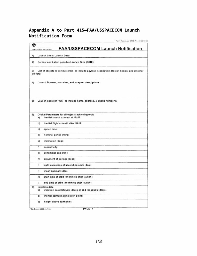
§ 417.125 Launch of an unguided suborbital launch vehicle.
(a) Applicability. This section applies only to a launch operator conducting a launch of an unguided suborbital launch vehicle.
(b) Need for flight safety system. A launch operator must launch an unguided suborbital launch vehicle with a flight safety system in accordance with §417.107 (a) and subpart D of this part unless one of the following exceptions applies:
(1) The unguided suborbital launch vehicle, including any component or payload, does not have sufficient energy to reach any populated area in any direction from the launch point; or
(2) A launch operator demonstrates through the licensing process that the launch will be conducted using a wind weighting safety system that meets the requirements of paragraph (c) of this section.
(c) Wind weighting safety system. A launch operator's wind weighting safety system must consist of equipment, procedures, analysis and personnel functions used to determine the launcher elevation and azimuth settings that correct for the windcocking and wind drift that an unguided suborbital launch vehicle will experience during flight due to wind effects. The launch of an unguided suborbital launch vehicle that uses a wind weighting safety system must meet the following requirements:
(1) The unguided suborbital launch vehicle must not contain a guidance or directional control system.
(2) The launcher azimuth and elevation settings must be wind weighted to correct for the effects of wind conditions at the time of flight to provide a safe impact location. A launch operator must conduct the launch in accordance with the wind weighting analysis requirements and methods of §417.233 and appendix C of this part.
(3) A launch operator must use a launcher elevation angle setting that ensures the rocket will not fly uprange. A launch operator must set the launcher elevation angle in accordance with the following:
(i) The nominal launcher elevation angle must not exceed 85°. The wind corrected launcher elevation setting must not exceed 86°.
(ii) For an unproven unguided suborbital launch vehicle, the nominal launcher elevation angle must not exceed 80°. The wind corrected launcher elevation setting must not exceed 84°. A proven unguided suborbital launch vehicle is one that has demonstrated, by two or more launches, that flight performance errors are within all the three-sigma dispersion parameters modeled in the wind weighting safety system.
136
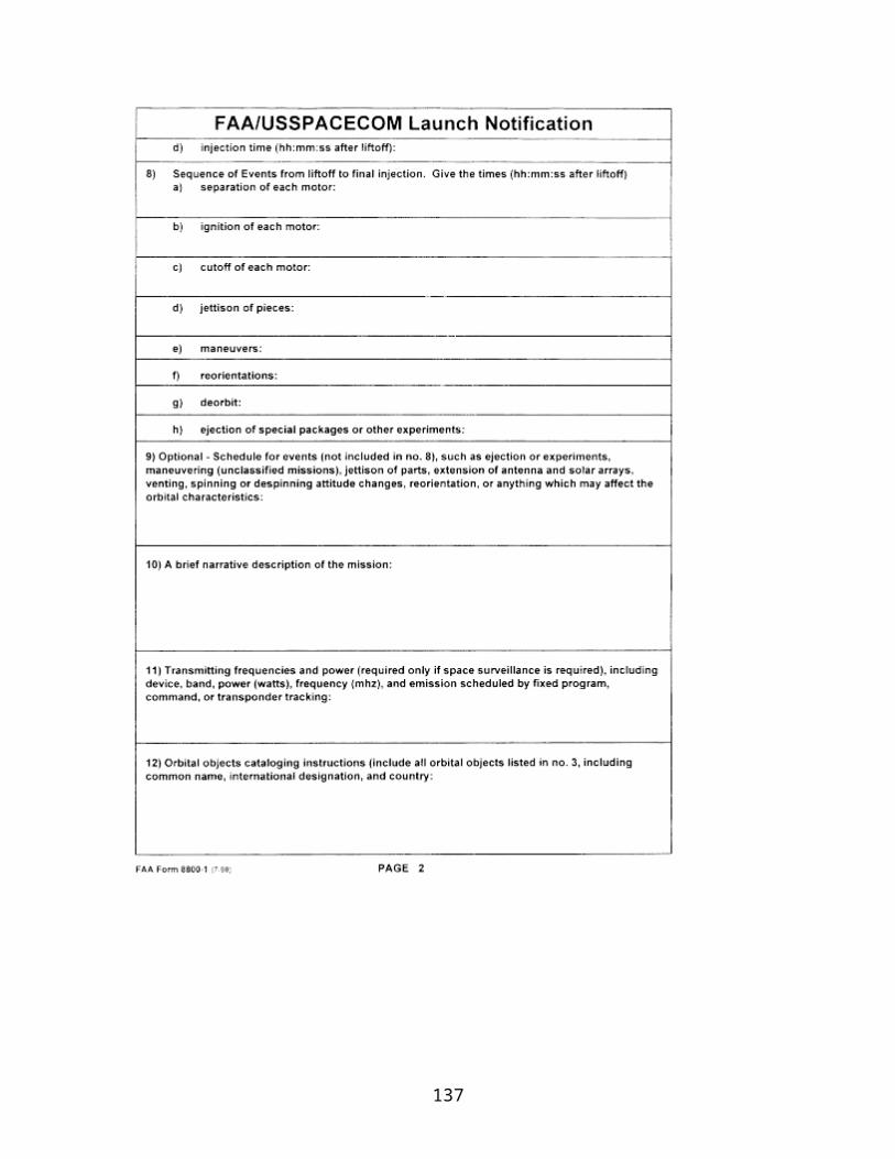
(d) Public risk criteria. A launch operator must conduct the launch of an unguided suborbital launch vehicle in accordance with the public risk criteria of §417.107(b). The risk to the public determined prior to the day of flight must satisfy the public risk criteria for the area defined by the range of nominal launch azimuths. A launch operator must not initiate flight until a launch operator has verified that the wind drifted impacts of all planned impacts and their five-sigma dispersion areas satisfy the public risk criteria after wind weighting on the day of flight.
(e) Stability. An unguided suborbital launch vehicle, in all configurations, must be stable in flexible body to 1.5 calibers and rigid body to 2.0 calibers throughout each stage of powered flight. A caliber, for a rocket configuration, is defined as the distance between the center of pressure and the center of gravity divided by the largest frontal diameter of the rocket configuration.
(f) Tracking. A launch operator must track the flight of an unguided suborbital launch vehicle. The tracking system must provide data to determine the actual impact locations of all stages and components, to verify the effectiveness of a launch operator's wind weighting safety system, and to obtain rocket performance data for comparison with the preflight performance predictions.
(g) Post-launch review. A launch operator must ensure that the post-launch report required by §417.25 includes:
(1) Actual impact location of all impacting stages and each impacting component.
(2) A comparison of actual and predicted nominal performance.
(3) Investigation results of any launch anomaly. If flight performance deviates by more than a three-sigma dispersion from the nominal trajectory, a launch operator must conduct an investigation to determine the cause of the rocket's deviation from normal flight and take corrective action before the next launch. A launch operator must file any corrective actions with the FAA as a request for license modification before the next launch in accordance with §417.11.
§ 417.127 Unique safety policies, requirements and practices.
For each launch, a launch operator must review operations, system designs, analysis, and testing, and identify any unique hazards not otherwise addressed by this part. A launch operator must implement any unique safety policy, requirement, or practice needed to protect the public from the unique hazard. A launch operator must demonstrate through the licensing process that any unique safety policy, requirement, or practice ensures the safety of the public. For any change to a unique safety policy, requirement, or practice, with the exception of a launch specific update, the launch operator must file a request for license modification as required by §417.11. The FAA may identify and impose a unique safety policy, requirement, or practice as needed to protect the public.
137

§ 417.129 Safety at end of launch.
A launch operator must ensure for any proposed launch that for all launch vehicle stages or components that reach Earth orbit—
(a) There is no unplanned physical contact between the vehicle or any of its components and the payload after payload separation;
(b) Debris generation does not result from the conversion of energy sources into energy that fragments the vehicle or its components. Energy sources include chemical, pressure, and kinetic energy; and
(c) Stored energy is removed by depleting residual fuel and leaving all fuel line valves open, venting any pressurized system, leaving all batteries in a permanent discharge state, and removing any remaining source of stored energy.
§§ 417.130--417.200 [Reserved]
Subpart C—Flight Safety Analysis
§ 417.201 Scope and applicability.
(a) This subpart contains requirements for performing the flight safety analysis required by §417.107(f).
(b) The flight safety analysis requirements of this subpart apply to the flight of any launch vehicle that must use a flight safety system as required by §417.107(a), except as permitted by paragraph (d) of this section.
(c) The flight safety analysis requirements of §§417.203, 417.205, 417.207, 417.211, 417.223, 417.224, 417.225, 417.227, 417.229, 417.231, and 417.233 apply to the flight of any unguided suborbital launch vehicle that uses a wind-weighting safety system. Appendices B, C, and I of this part also apply.
(d) For any alternative flight safety system approved by the FAA under §417.301(b), the FAA will determine during the licensing process which of the analyses required by this subpart apply.
§ 417.203 Compliance.
(a) General. A launch operator's flight safety analysis must satisfy the performance requirements of this subpart. The flight safety analysis must also meet the requirements for methods of analysis contained in appendices A and B of this part for a launch vehicle flown with a flight safety system and appendices B and C of this part for an unguided suborbital launch vehicle that uses a wind-weighting safety system except as otherwise
138

permitted by this section. A flight safety analysis for a launch may rely on an earlier analysis from an identical or similar launch if the analysis still applies to the later launch.
(b) Method of analysis. (1) For each launch, a launch operator's flight safety analysis must use—
(i) A method approved by the FAA during the licensing process;
(ii) A method approved as a license modification by the FAA; or,
(iii) If the launch takes place from a Federal launch range, a method approved as part of the FAA's launch site safety assessment of the Federal range's processes.
(2) Appendix A of this part contains requirements that apply to all methods of flight safety analysis. A licensee must notify the FAA for any change to the flight safety analysis method. A licensee must file any material change with the FAA as a request for license modification before the launch to which the proposed change would apply. Section 417.11 contains requirements governing a license modification.
(c) Alternate analysis method. The FAA will approve an alternate flight safety analysis method if a launch operator demonstrates, in accordance with §406.3(b), that its proposed analysis method provides an equivalent level of fidelity to that required by this subpart. A launch operator must demonstrate that an alternate flight safety analysis method is based on accurate data and scientific principles and is statistically valid. The FAA will not find a launch operator's application for a license or license modification sufficiently complete to begin review under §413.11 of this chapter until the FAA approves the alternate flight safety analysis method.
(d) Analyses performed by a Federal launch range. This provision applies to all sections of this subpart. The FAA will accept a flight safety analysis used by a Federal launch range without need for further demonstration of compliance to the FAA, if:
(1) A launch operator has contracted with a Federal launch range for the provision of flight safety analysis; and
(2) The FAA has assessed the Federal launch range, through its launch site safety assessment, and found that the range's analysis methods satisfy the requirements of this subpart. In this case, the FAA will treat the Federal launch range's analysis as that of a launch operator.
(e) Analysis products. For a licensed launch that does not satisfy paragraph (d) of this section, a launch operator must demonstrate to the FAA compliance with the requirements of this subpart, and must include in its demonstration the analysis products required by part 415 subpart F of this chapter, part 417 subpart A, and appendices A, B, C, and I of this part, depending on whether the launch vehicle uses a flight safety system or a wind-weighting safety system.
139

§ 417.205 General.
(a) Public risk management. A flight safety analysis must demonstrate that a launch operator will, for each launch, control the risk to the public from hazards associated with normal and malfunctioning launch vehicle flight. The analysis must employ risk assessment, hazard isolation, or a combination of risk assessment and partial isolation of the hazards, to demonstrate control of the risk to the public.
(1) Risk assessment. When demonstrating control of risk through risk assessment, the analysis must demonstrate that any risk to the public satisfies the public risk criteria of §417.107(b). The analysis must account for the variability associated with:
(i) Each source of a hazard during flight;
(ii) Normal flight and each failure response mode of the launch vehicle;
(iii) Each external and launch vehicle flight environment;
(iv) Populations potentially exposed to the flight; and
(v) The performance of any flight safety system, including time delays associated with the system.
(2) Hazard isolation. When demonstrating control of risk through hazard isolation, the analysis must establish the geographical areas from which the public must be excluded during flight and any operational controls needed to isolate all hazards from the public.
(3) Combination of risk assessment and partial isolation of hazards. When demonstrating control of risk through a combination of risk assessment and partial isolation of the hazards from the public, the analysis must demonstrate that the residual public risk due to any hazard not isolated from the public under paragraph (a)(2) of this section satisfies the public risk criteria of §417.107(b).
(b) Dependent analyses. Because some analyses required by this subpart are inherently dependent on one another, the data output of any one analysis must be compatible in form and content with the data input requirements of any other analysis that depends on that output. Figure 417.205–1 illustrates the flight safety analyses that might be performed for a launch flown with a flight safety system and the typical dependencies that might exist among the analyses.
140

§ 417.207 Trajectory analysis.
(a) General . A flight safety analysis must include a trajectory analysis that establishes:
(1) For any time after lift-off, the limits of a launch vehicle's normal flight, as defined by the nominal trajectory and potential three-sigma trajectory dispersions about the nominal trajectory.
(2) A fuel exhaustion trajectory that produces instantaneous impact points with the greatest range for any given time after liftoff for any stage that has the potential to impact the Earth and does not burn to propellant depletion before a programmed thrust termination.
141
(3) For launch vehicles flown with a flight safety system, a straight-up trajectory for any time after lift-off until the straight-up time that would result if the launch vehicle malfunctioned and flew in a vertical or near vertical direction above the launch point.
(b) Trajectory model. A final trajectory analysis must use a six-degree of freedom trajectory model to satisfy the requirements of paragraph (a) of this section.
(c) Wind effects. A trajectory analysis must account for all wind effects, including profiles of winds that are no less severe than the worst wind conditions under which flight might be attempted, and must account for uncertainty in the wind conditions.
§ 417.209 Malfunction turn analysis.
(a) General. A flight safety analysis must include a malfunction turn analysis that establishes the launch vehicle's turning capability in the event of a malfunction during flight. A malfunction turn analysis must account for each cause of a malfunction turn, such as thrust vector offsets or nozzle burn-through. For each cause of a malfunction turn, the analysis must establish the launch vehicle's turning capability using a set of turn curves. The analysis must account for:
(1) All trajectory times during the thrusting phases of flight.
(2) When a malfunction begins to cause each turn throughout the thrusting phases of flight. The analysis must account for trajectory time intervals between malfunction turn start times that are sufficient to establish flight safety limits and hazard areas that are smooth and continuous.
(3) The relative probability of occurrence of each malfunction turn of which the launch vehicle is capable.
(4) The time, as a single value or a probability time distribution, when each malfunction turn will terminate due to vehicle breakup.
(5) What terminates each malfunction turn, such as, aerodynamic breakup or inertial breakup.
(6) The launch vehicle's turning behavior from the time when a malfunction begins to cause a turn until aerodynamic breakup, inertial breakup, or ground impact. The analysis must account for trajectory time intervals during the malfunction turn that are sufficient to establish turn curves that are smooth and continuous.
(7) For each malfunction turn, the launch vehicle velocity vector turn angle from the nominal launch vehicle velocity vector.
(8) For each malfunction turn, the launch vehicle velocity turn magnitude from the nominal velocity magnitude that corresponds to the velocity vector turn angle.
142

(9) For each malfunction turn, the orientation of the launch vehicle longitudinal axis measured relative to the nominal launch vehicle longitudinal axis or Earth relative velocity vector at the start of the turn.
(b) Set of turn curves for each malfunction turn cause. For each cause of a malfunction turn, the analysis must establish a set of turn curves that satisfies paragraph (a) of this section and must establish the associated envelope of the set of turn curves. Each set of turn curves must describe the variation in the malfunction turn characteristics for each cause of a turn. The envelope of each set of curves must define the limits of the launch vehicle's malfunction turn behavior for each cause of a malfunction turn. For each malfunction turn envelope, the analysis must establish the launch vehicle velocity vector turn angle from the nominal launch vehicle velocity vector. For each malfunction turn envelope, the analysis must establish the vehicle velocity turn magnitude from the nominal velocity magnitude that corresponds to the velocity vector turn angle envelope.
§ 417.211 Debris analysis.
(a) General. A flight safety analysis must include a debris analysis. For an orbital or suborbital launch, a debris analysis must identify the inert, explosive, and other hazardous launch vehicle debris that results from normal and malfunctioning launch vehicle flight.
(b) Launch vehicle breakup. A debris analysis must account for each cause of launch vehicle breakup, including at a minimum:
(1) Any flight termination system activation;
(2) Launch vehicle explosion;
(3) Aerodynamic loads;
(4) Inertial loads;
(5) Atmospheric reentry heating; and
(6) Impact of intact vehicle.
(c) Debris fragment lists. A debris analysis must produce lists of debris fragments for each cause of breakup and any planned jettison of debris, launch vehicle components, or payload. The lists must account for all launch vehicle debris fragments, individually or in groupings of fragments whose characteristics are similar enough to be described by a single set of characteristics. The debris lists must describe the physical, aerodynamic, and harmful characteristics of each debris fragment, including at a minimum:
(1) Origin on the vehicle, by vehicle stage or component, from which each fragment originated;
143

(2) Whether it is inert or explosive;
(3) Weight, dimensions, and shape;
(4) Lift and drag characteristics;
(5) Properties of the incremental velocity distribution imparted by breakup; and
(6) Axial, transverse, and tumbling area.
§ 417.213 Flight safety limits analysis.
(a) General. A flight safety analysis must identify the location of populated or other protected areas, and establish flight safety limits that define when a flight safety system must terminate a launch vehicle's flight to prevent the hazardous effects of the resulting debris impacts from reaching any populated or other protected area and ensure that the launch satisfies the public risk criteria of §417.107(b).
(b) Flight safety limits. The analysis must establish flight safety limits for use in establishing flight termination rules. Section 417.113(c) contains requirements for flight termination rules. The flight safety limits must account for all temporal and geometric extents on the Earth's surface of a launch vehicle's hazardous debris impact dispersion resulting from any planned or unplanned event for all times during flight. Flight safety limits must account for all potential contributions to the debris impact dispersions, including at a minimum:
(1) All time delays, as established by the time delay analysis of §417.221;
(2) Residual thrust remaining after flight termination implementation or vehicle breakup due to aerodynamic and inertial loads;
(3) All wind effects;
(4) Velocity imparted to vehicle fragments by breakup;
(5) All lift and drag forces on the malfunctioning vehicle and falling debris;
(6) All launch vehicle guidance and performance errors;
(7) All launch vehicle malfunction turn capabilities; and
(8) Any uncertainty due to map errors and launch vehicle tracking errors.
(c) Gates. If a launch involves flight over any populated or other protected area, the flight safety analysis must establish a gate as required by §§417.217 and 417.218.
144

(d) Designated debris impact limits. The analysis must establish designated impact limit lines to bound the area where debris with a ballistic coefficient of three or more is allowed to impact if the flight safety system functions properly.
§ 417.215 Straight-up time analysis.
A flight safety analysis must establish the straight-up time for a launch for use as a flight termination rule. Section 417.113(c) contains requirements for flight termination rules. The analysis must establish the straight-up time as the latest time after liftoff, assuming a launch vehicle malfunctioned and flew in a vertical or near vertical direction above the launch point, at which activation of the launch vehicle's flight termination system or breakup of the launch vehicle would not cause hazardous debris or critical overpressure to affect any populated or other protected area.
§ 417.217 Overflight gate analysis.
For a launch that involves flight over a populated or other protected area, the flight safety analysis must include an overflight gate analysis. The analysis must establish the portion of a flight safety limit, a gate, through which a normally performing launch vehicle's tracking icon will be allowed to proceed. A tracking icon must enable the flight safety crew to determine whether the launch vehicle's flight is in compliance with the flight safety rules established under §417.113. When establishing that portion of a flight safety limit, the analysis must demonstrate that the launch vehicle flight satisfies the flight safety requirements of §417.107.
§ 417.218 Hold-and-resume gate analysis.
(a) For a launch that involves overflight or near overflight of a populated or otherwise protected area prior to the planned safe flight state calculated as required by §417.219, the flight safety analysis must construct a hold-and-resume gate for each populated or otherwise protected area. After a vehicle's tracking icon crosses a hold-and-resume gate, flight termination must occur as required by sections 417.113(d)(6).
(b) The hold-and-resume gate analysis must account for:
(1) Overflight of a wholly contained populated or otherwise protected area. A hold-and-resume gate must be a closed, continuous contour that encompasses any populated or otherwise protected area located wholly within the impact limit lines. The hold-and-resume gate must encompass a populated or otherwise protected area such that flight termination or breakup of the launch vehicle while the tracking icon is outside the gate would not cause hazardous debris or overpressure to endanger the populated or otherwise protected area.
(2) Overflight of an uncontained populated or otherwise protected area. A hold-and-resume gate must be a closed, continuous contour that encompasses any area in which flight termination is allowed to occur. The hold-and-resume gate must encompass all
145
hazard areas such that flight termination or breakup of the launch vehicle while the vehicle's tracking icon is inside the gate would not cause hazardous debris or critical overpressure to endanger any populated or otherwise protected area.
§ 417.219 Data loss flight time and planned safe flight state analyses.
(a) General. For each launch, a flight safety analysis must establish data loss flight times, as identified by paragraph (b) of this section, and a planned safe flight state to establish each flight termination rule that applies when launch vehicle tracking data is not available for use by the flight safety crew. Section 417.113(d) contains requirements for flight termination rules.
(b) Data loss flight times. A flight safety analysis must establish the shortest elapsed thrusting time during which a launch vehicle can move from normal flight to a condition where the launch vehicle's hazardous debris impact dispersion extends to any protected area as a data loss flight time. The analysis must establish a data loss flight time for all times along the nominal trajectory from liftoff through that point during nominal flight when the minimum elapsed thrusting time is no greater than the time it would take for a normal vehicle to reach the overflight gate, or the planned safe flight state established under paragraph (c) of this section, whichever occurs earlier.
(c) Planned safe flight state. For a launch vehicle that performs normally during all portions of flight, the planned safe flight state is the point during the nominal flight of a launch vehicle where:
(1) No launch vehicle component, debris, or hazard can impact or affect a populated or otherwise protected area for the remainder of the launch;
(2) The launch vehicle achieves orbital insertion; or
(3) The launch vehicle's state vector reaches a state where the absence of a flight safety system would not significantly increase the accumulated risk from debris impacts and maintains positive flight safety system control to the maximum extent feasible.
§ 417.221 Time delay analysis.
(a) General. A flight safety analysis must include a time delay analysis that establishes the mean elapsed time between the violation of a flight termination rule and the time when the flight safety system is capable of terminating flight for use in establishing flight safety limits as required by §417.213.
(b) Analysis constraints. A time delay analyses must determine a time delay distribution that accounts for the following:
146
(1) The variance of all time delays for each potential failure scenario, including but not limited to, the range of malfunction turn characteristics and the time of flight when the malfunction occurs;
(2) A flight safety official's decision and reaction time, including variation in human response time; and
(3) Flight termination hardware and software delays including all delays inherent in:
(i) Tracking systems;
(ii) Data processing systems, including all filter delays;
(iii) Display systems;
(iv) Command control systems; and
(v) Flight termination systems.
§ 417.223 Flight hazard area analysis.
(a) General. A flight safety analysis must include a flight hazard area analysis that identifies any regions of land, sea, or air that must be surveyed, publicized, controlled, or evacuated in order to control the risk to the public from debris impact hazards. The risk management requirements of §417.205(a) apply. The analysis must account for, at a minimum:
(1) All trajectory times from liftoff to the planned safe flight state of §417.219(c), including each planned impact, for an orbital launch, and through final impact for a suborbital launch;
(2) Regions of land potentially exposed to debris resulting from normal flight events and events resulting from any potential malfunction;
(3) Regions of sea and air potentially exposed to debris from normal flight events, including planned impacts;
(4) In the vicinity of the launch site, any waterborne vessels, populated offshore structures, or aircraft exposed to debris from events resulting from any potential abnormal flight events, including launch vehicle malfunction;
(5) Any operational controls implemented to control risk to the public from debris hazards;
(6) Debris identified by the debris analysis of §417.211; and
147

(7) All launch vehicle trajectory dispersion effects in the surface impact domain.
(b) Public notices. A flight hazard areas analysis must establish the ship hazard areas for notices to mariners that encompass the three-sigma impact dispersion area for each planned debris impact. A flight hazard areas analysis must establish the aircraft hazard areas for notices to airmen that encompass the 3-sigma impact dispersion volume for each planned debris impact. Section 417.121(e) contains procedural requirements for issuing notices to mariners and airmen.
§ 417.224 Probability of failure analysis.
(a) General. All flight safety analyses for a launch, regardless of hazard or phase of flight, must account for launch vehicle failure probability in a consistent manner. A launch vehicle failure probability estimate must use accurate data, scientific principles, and a method that is statistically or probabilistically valid. For a launch vehicle with fewer than two flights, the failure probability estimate must account for the outcome of all previous launches of vehicles developed and launched in similar circumstances. For a launch vehicle with two or more flights, launch vehicle failure probability estimates must account for the outcomes of all previous flights of the vehicle in a statistically valid manner.
(b) Failure. For flight safety analysis purposes, a failure occurs when a launch vehicle does not complete any phase of normal flight or when any anomalous condition exhibits the potential for a stage or its debris to impact the Earth or reenter the atmosphere during the mission or any future mission of similar launch vehicle capability. Also, either a launch incident or launch accident constitutes a failure.
(c) Previous flight. For flight analysis purposes, flight begins at a time in which a launch vehicle normally or inadvertently lifts off from a launch platform. Lift-off occurs with any motion of the launch vehicle with respect to the launch platform.
§ 417.225 Debris risk analysis.
A flight safety analysis must demonstrate that the risk to the public potentially exposed to inert and explosive debris hazards from any one flight of a launch vehicle satisfies the public risk criterion of §417.107(b) for debris. A debris risk analysis must account for risk to populations on land, including regions of launch vehicle flight following passage through any gate in a flight safety limit established as required by §417.217. A debris risk analysis must account for any potential casualties to the public as required by the debris thresholds and requirements of §417.107(c).
§ 417.227 Toxic release hazard analysis.
A flight safety analysis must establish flight commit criteria that protect the public from any hazard associated with toxic release and demonstrate compliance with the public risk criterion of §417.107(b). The analysis must account for any toxic release that will occur
148
during the proposed flight of a launch vehicle or that would occur in the event of a flight mishap. The analysis must account for any operational constraints and emergency procedures that provide protection from toxic release. The analysis must account for all members of the public that may be exposed to the toxic release, including all members of the public on land and on any waterborne vessels, populated offshore structures, and aircraft that are not operated in direct support of the launch.
§ 417.229 Far-field overpressure blast effects analysis.
(a) General. A flight safety analysis must establish flight commit criteria that protect the public from any hazard associated with far field blast overpressure effects due to potential explosions during launch vehicle flight and demonstrate compliance with the public risk criterion of §417.107(b).
(b) Analysis constraints. The analysis must account for:
(1) The potential for distant focus overpressure or overpressure enhancement given current meteorological conditions and terrain characteristics;
(2) The potential for broken windows due to peak incident overpressures below 1.0 psi and related casualties;
(3) The explosive capability of the launch vehicle at impact and at altitude and potential explosions resulting from debris impacts, including the potential for mixing of liquid propellants;
(4) Characteristics of the launch vehicle flight and the surroundings that would affect the population's susceptibility to injury, such as, shelter types and time of day of the proposed launch;
(5) Characteristics of the potentially affected windows, including their size, location, orientation, glazing material, and condition; and
(6) The hazard characteristics of the potential glass shards, such as falling from upper building stories or being propelled into or out of a shelter toward potentially occupied spaces.
§ 417.231 Collision avoidance analysis.
(a) General. A flight safety analysis must include a collision avoidance analysis that establishes each launch wait in a planned launch window during which a launch operator must not initiate flight, in order to protect any maned or mannable orbiting object. A launch operator must account for uncertainties associated with launch vehicle performance and timing and ensure that any calculated launch waits incorporate all additional time periods associated with such uncertainties. A launch operator must implement any launch waits as flight commit criteria according to §417.113(b).
149
(b) Orbital launch. For an orbital launch, the analysis must establish any launch waits needed to ensure that the launch vehicle, any jettisoned components, and its payload do not pass closer than 200 kilometers to a manned or mannable orbiting object during ascent to initial orbital insertion through at least one complete orbit.
(c) Suborbital launch. For a suborbital launch, the analysis must establish any launch waits needed to ensure that the launch vehicle, any jettisoned components, and any payload do not pass closer than 200 kilometers to a manned or mannable orbital object throughout the flight.
(d) Analysis not required. A collision avoidance analysis is not required if the maximum altitude attainable by a launch operator's unguided suborbital launch vehicle is less than the altitude of the lowest manned or mannable orbiting object. The maximum altitude attainable must be obtained using an optimized trajectory, assuming 3-sigma maximum performance.
§ 417.233 Analysis for an unguided suborbital launch vehicle flown with a wind weighting safety system.
For each launch of an unguided suborbital launch vehicle flown with a wind weighting safety system, in addition to the other requirements in this subpart outlined in §417.201(c), the flight safety analysis must:
(a) Establish flight commit criteria and other launch safety rules that a launch operator must implement to control the risk to the public from potential adverse effects resulting from normal and malfunctioning flight;
(b) Establish any wind constraints under which launch may occur; and
(c) Include a wind weighting analysis that establishes the launcher azimuth and elevation settings that correct for the windcocking and wind-drift effects on the unguided suborbital launch vehicle.
Subpart D—Flight Safety System
§ 417.301 General.
(a) Applicability. This subpart applies to any flight safety system that a launch operator uses. The requirements of §417.107(a) define when a launch operator must use a flight safety system. A launch operator must ensure that its flight safety system satisfies all the requirements of this subpart, including the referenced appendices. Paragraph (b) of this section provides an exception to this.
(b) Alternate flight safety system. A flight safety system need not satisfy one or more of the requirements of this subpart for a launch if a launch operator demonstrates, in accordance with §406.3(b), that the launch achieves an equivalent level of safety as a
150

launch that satisfies all the requirements of this part. The flight safety system must undergo analysis and testing that is comparable to that required by this part to demonstrate that the system's reliability to perform each intended function is comparable to that required by this subpart.
(c) Functions, subsystems, and components. When initiated in the event of a launch vehicle failure, a flight safety system must prevent any launch vehicle hazard, including any payload hazard, from reaching a populated or other protected area. A flight safety system must consist of all of the following:
(1) A flight termination system that satisfies appendices D, E, and F of this part;
(2) A command control system that satisfies §§417.303 and 417.305;
(3) Each support system required by §417.307; and
(4) The functions of any personnel who operate flight safety system hardware or software including a flight safety crew that satisfies §417.311.
(d) Compliance —(1) Non-Federal launch site. For launch from a non-Federal launch site, any flight safety system, including all components, must:
(1) Non-Federal launch site. For launch from a non-Federal launch site, any flight safety system, including all components, must:
(i) Comply with a launch operator's flight safety system compliance matrix of §415.127(g) that accounts for all the design, installation, and monitoring requirements of this subpart, including the referenced appendices; and
(ii) Comply with a launch operator's testing compliance matrix of §415.129(b) that accounts for all the test requirements of this subpart, including the referenced appendices.
(2) Federal launch range. This provision applies to all sections of this subpart. The FAA will accept a flight safety system used or approved on a Federal launch range without need for further demonstration of compliance to the FAA if:
(i) A launch operator has contracted with a Federal launch range for the provision of flight safety system property and services; and
(ii) The FAA has assessed the Federal launch range, through its launch site safety assessment, and found that the Federal launch range's flight safety system property and services satisfy the requirements of this subpart. In this case, the FAA will treat the Federal launch range's flight safety system property and services as that of a launch operator.
§ 417.303 Command control system requirements.
151
(a) General. When initiated by a flight safety official, a command control system must transmit a command signal that has the radio frequency characteristics and power needed for receipt of the signal by the onboard vehicle flight termination system. A command control system must include all of the following:
(1) All flight termination system activation switches;
(2) All intermediate equipment, linkages, and software;
(3) Any auxiliary stations;
(4) Each command transmitter and transmitting antenna; and
(5) All support equipment that is critical for reliable operation, such as power, communications, and air conditioning systems.
(b) Performance specifications. A command control system and each subsystem, component, and part that can affect the reliability of a component must have written performance specifications that demonstrate, and contain the details of, how each satisfies the requirements of this section.
(c) Reliability prediction. A command control system must have a predicted reliability of 0.999 at the 95 percent confidence level when operating, starting with completion of the preflight testing and system verification of §417.305(c) through initiation of flight and until the planned safe flight state for each launch. Any demonstration of the system's predicted reliability must satisfy §417.309(b).
(d) Fault tolerance. A command control system must not contain any single-failure-point that, upon failure, would inhibit the required functioning of the system or cause the transmission of an undesired flight termination message. A command control system's design must ensure that the probability of transmitting an undesired or inadvertent command during flight is less than 1 × 10⁻⁷.
(e) Configuration control. A command control system must undergo configuration control to ensure its reliability and compatibility with the flight termination system used for each launch.
(f) Electromagnetic interference. Each command control system component must function within the electromagnetic environment to which it is exposed. A command control system must include protection to prevent interference from inhibiting the required functioning of the system or causing the transmission of an undesired or inadvertent flight termination command. Any susceptible remote control data processing or transmitting system that is part of the command control system must prevent electromagnetic interference.
152

(g) Command transmitter failover. A command control system must include independent, redundant transmitter systems that automatically switch, or “fail-over,” from a primary transmitter to a secondary transmitter when a condition exists that indicates potential failure of the primary transmitter. The switch must be automatic and provide all the same command control system capabilities through the secondary transmitter system. The secondary transmitter system must respond to any transmitter system configuration and radio message orders established for the launch. The fail-over criteria that trigger automatic switching from the primary transmitter to the secondary transmitter must account for each of the following transmitter performance parameters and failure indicators:
(1) Low transmitter power;
(2) Center frequency shift;
(3) Out of tolerance tone frequency;
(4) Out of tolerance message timing;
(5) Loss of communication between central control and transmitter site;
(6) Central control commanded status and site status disagree;
(7) Transmitter site fails to respond to a configuration or radiation order within a specified period of time; and
(8) For a tone-based system, tone deviation and tone imbalance.
(h) Switching between transmitter systems. Any manual or automatic switching between transmitter systems, including fail-over, must not result in the radio carrier being off the air long enough for any command destruct system to be captured by an unauthorized transmitter. The time the radio carrier is off the air must account for any loss of carrier and any simultaneous multiple radio carrier transmissions from two transmitter sites during switching.
(i) Radio carrier. For each launch, a command control system must provide all of the following:
(1) The radio frequency signal and radiated power density that each command destruct system needs to activate during flight;
(2) The 12-dB power density margin required by section D417.9(d) of appendix D of this part under nominal conditions; and
(3) A 6-dB power density margin under worst-case conditions.
153

(j) Command control system monitoring and control. A command control system must provide for monitoring and control of the system from the flight safety system displays and controls required by §417.307(g), including real-time selection of a transmitter, transmitter site, communication circuits, and antenna configuration.
(k) Command transmitter system. For each launch, a command transmitter system must:
(1) Transmit signals that are compatible with any command destruct system's radio frequency receiving system of section D417.25 and command receiver decoder of section D417.29 of appendix D of this part;
(2) Ensure that all arm and destruct commands transmitted to a flight termination system have priority over any other commands transmitted;
(3) Employ an authorized radio carrier frequency and bandwidth with a guard band that provides the radio frequency separation needed to ensure that the system does not interfere with any other flight safety system that is required to operate at the same time;
(4) Transmit an output bandwidth that is consistent with the signal spectrum power used in the link analysis of §417.309(f); and
(5) Not transmit other frequencies that could degrade the airborne flight termination system's performance.
(l) Command control system antennas. A command control system antenna or antenna system must satisfy all of the following:
(1) The antenna system must provide two or more command signals to any command destruct system throughout normal flight and in the event of a launch vehicle failure regardless of launch vehicle orientation;
(2) Each antenna beam-width must:
(i) Allow for complete transmission of the command destruct sequence of signal tones before a malfunctioning launch vehicle can exit the 3-dB point of the antenna pattern;
(ii) When the vehicle is centered in the antenna pattern at the beginning of the malfunction, account for the launch vehicle's malfunction turn capability determined by the analysis of §417.209, the data loss flight times of §417.219, and the time delay of §417.221.
(iii) Encompass the boundaries of normal flight for the portion of flight that the antenna is scheduled to support; and
(iv) Account for any error associated with launch vehicle tracking and pointing of the antenna;
154

(3) The location of each antenna must provide for an unobstructed line of site between the antenna and the launch vehicle;
(4) The antenna system must provide a continuous omni-directional radio carrier pattern that covers the launch vehicle's flight from the launch point to no less than an altitude of 50,000 feet above sea level, unless the system uses a steerable antenna that satisfies paragraphs (l)(1) and (2) of this section for the worst-case launch vehicle malfunction that could occur during that portion of flight;
(5) An antenna must radiate circularly polarized radio waves that are compatible with the flight termination system antennas on the launch vehicle; and
(6) Any steerable antenna must allow for control of the antenna manually at the antenna site or by remote slaving data from a launch vehicle tracking source. A steerable antenna's positioning lag, accuracy, and slew rates must allow for tracking a nominally performing launch vehicle within one half of the antenna's beam-width and for tracking a malfunctioning launch vehicle to satisfy paragraph (l)(2) of this section.
§ 417.305 Command control system testing.
(a) General. (1) A command control system, including its subsystems and components must undergo the acceptance testing of paragraph (b) of this section when new or modified. For each launch, a command control system must undergo the preflight testing of paragraph (c) of this section.
(2) Each acceptance and preflight test must follow a written test plan that specifies the procedures and test parameters for the test and the testing sequence. A test plan must include instructions on how to handle procedural deviations and how to react to test failures.
(3) If hardware or software is redesigned or replaced with a different hardware or software that is not identical to the original, the system must undergo all acceptance testing and analysis with the new hardware or software and all preflight testing for each launch with the new hardware or software.
(4) After a command control system passes all acceptance tests, if a component is replaced with an identical component, the system must undergo testing to ensure that the new component is installed properly and is operational.
(b) Acceptance testing. (1) All new or modified command control system hardware and software must undergo acceptance testing to verify that the system satisfies the requirements of §417.303.
(2) Acceptance testing must include functional testing, system interface validation testing, and integrated system-wide validation testing.
155

(3) Each acceptance test must measure the performance parameters that demonstrate whether the requirements of §417.303 are satisfied.
(4) Any computing system, software, or firmware that performs a software safety critical function must undergo validation testing and satisfy §417.123. If command control system hardware interfaces with software, the interface must undergo validation testing.
(c) Preflight testing —(1) General. For each launch, a command control system must undergo preflight testing to verify that the system satisfies the requirements of §417.303 for the launch.
(1) General. For each launch, a command control system must undergo preflight testing to verify that the system satisfies the requirements of §417.303 for the launch.
(2) Coordinated command control system and flight termination system testing. For each launch, a command control system must undergo preflight testing during the preflight testing of the associated flight termination system under section E417.41 of appendix E of this part.
(3) Command transmitter system carrier switching tests. A command transmitter system must undergo a test of its carrier switching system no earlier than 24 hours before a scheduled flight. The test must satisfy all of the following:
(i) Automatic carrier switching. For any automatic carrier switching system, the test must verify that the switching algorithm selects and enables the proper transmitter site for each portion of the planned flight; and
(ii) Manual carrier switching. For any manual carrier switching, the test must verify that the flight safety system crew can select and enable each transmitter site planned to support the launch.
(4) Independent radio frequency open loop verification tests. A command control system must undergo an open loop end-to-end verification test for each launch as close to the planned flight as operationally feasible and after any modification to the system or break in the system configuration. The test must:
(i) Verify the performance of each element of the system from the flight safety system displays and controls to each command transmitter site;
(ii) Measure all system performance parameters received and transmitted using measuring equipment that does not physically interface with any elements of the operational command control system;
(iii) Verify the performance of each flight safety system display and control and remote command transmitter site combination by repeating all measurements for each
156

combination, for all strings and all operational configurations of cross-strapped equipment; and
(iv) Verify that all critical command control system performance parameters satisfy all their performance specifications. These parameters must include:
(A) Transmitter power output;
(B) Center frequency stability;
(C) Tone deviation;
(D) Tone frequency;
(E) Message timing;
(F) Status of each communication circuit between the flight safety system display and controls and any supporting command transmitter sites;
(G) Status agreement between the flight safety system display and controls and each and any supporting command transmitter sites;
(H) Fail-over conditions;
(I) Tone balance; and
(J) Time delay from initiation of a command at each flight safety system control to transmitter output of the command signal.
(d) Test reports. If a Federal launch range oversees the safety of a launch, the range's requirements are consistent with this subpart, and the range provides and tests the command control system, a launch operator need only obtain the range's verification that the system satisfies all the test requirements. For any other case a launch operator must prepare or obtain one or more written reports that:
(1) Verify that the command control system satisfies all the test requirements;
(2) Describe all command control system test results and test conditions;
(3) Describe any analysis performed instead of testing;
(4) Identify by serial number or other identification each test result that applies to each system or component;
157

(5) Describe any test failure or anomaly, including any variation from an established performance baseline, each corrective action taken, and all results of any additional tests; and
(6) Identify any test failure trends.
§ 417.307 Support systems.
(a) General. (1) A flight safety system must include the systems required by this section to support the functions of the flight safety system crew, including making a flight termination decision.
(2) Each support system and each subsystem, component, and part that can affect the reliability of the support system must have written performance specifications that demonstrate, and contain the details of, how each satisfies the requirements of this section.
(3) For each launch, each support system must undergo testing to ensure it functions according to its performance specifications.
(b) Launch vehicle tracking. (1) A flight safety system must include a launch vehicle tracking system that provides launch vehicle position and status data to the flight safety crew from the first data loss flight time until the planned safe flight state for the launch.
(2) The tracking system must consist of at least two sources of launch vehicle position data. The data sources must be independent of one another, and at least one source must be independent of any vehicle guidance system.
(3) All ground tracking systems and components must be compatible with any tracking system components onboard the launch vehicle.
(4) If a tracking system uses radar as one of the independent tracking sources, the system must:
(i) Include a tracking beacon onboard the launch vehicle; or
(ii) If the system relies on skin tracking, it must maintain a tracking margin of no less than 6 dB above noise throughout the period of flight that the radar is used. The flight safety limits must account for the larger tracking errors associated with skin tracking.
(5) The tracking system must provide real-time data to the flight safety data processing, display, and recording system required by paragraph (e) of this section.
(6) For each launch, each tracking source must undergo validation of its accuracy. For each stage of flight that a launch vehicle guidance system is used as a tracking source, a tracking source that is independent of any system used to aid the guidance system must
158

validate the guidance system data before the data is used in the flight termination decision process.
(7) The launch vehicle tracking error from all sources, including data latency and any possible gaps or dropouts in tracking coverage, must be consistent with the flight safety limits of §417.213 and the flight safety system time delay of §417.221.
(8) Any planned gap in tracking coverage must not occur at the same time as any planned switching of command transmitters.
(c) Telemetry. (1) A flight safety system must include a telemetry system that provides the flight safety crew with accurate flight safety data during preflight operations and during flight until the planned safe flight state.
(2) The onboard telemetry system must monitor and transmit the flight termination system monitoring data of section D417.17 and any launch vehicle tracking data used to satisfy paragraph (b) of this section.
(3) The telemetry receiving system must acquire, store, and provide real-time data to the flight safety data processing, display, and recording system required by paragraph (e) of this section.
(d) Communications network. A flight safety system must include a communications network that connects all flight safety functions with all launch control centers and any down-range tracking and command transmitter sites. The system must provide for recording all required data and all voice communications channels during launch countdown and flight.
(e) Data processing, display, and recording. A flight safety system must include one or more subsystems that process, display, and record flight safety data to support the flight safety crew's monitoring of the launch, including the data that the crew uses to make a flight termination decision. The system must:
(1) Satisfy §417.123 for any computing system, software, or firmware that must operate properly to ensure the accuracy of the data;
(2) Receive vehicle status data from tracking and telemetry, evaluate the data for validity, and provide valid data for display and recording;
(3) Perform any reformatting of the data as appropriate and forward it to display and recording devices;
(4) Display real-time data against background displays of the nominal trajectory and flight safety limits established in accordance with the flight safety analysis required by subpart C of this part;
159
(5) Display and record raw input and processed data at a rate that maintains the validity of the data and at no less than 0.1-second intervals;
(6) Record the timing of when flight safety system commands are input by the flight safety crew; and
(7) Record all health and status parameters of the command control system, including the transmitter failover parameters, command outputs, check channel or pilot tone monitor, and status of communications.
(f) Displays and controls. (1) A flight safety system must include the displays of real-time data and controls that the flight safety crew needs to perform all its functions, such as to monitor and evaluate launch vehicle performance, communicate with other flight safety and launch personnel, and initiate flight termination.
(2) A flight safety system must present all data that the flight safety crew needs to ensure that all flight commit criteria are satisfied for each launch, such as hazard area surveillance, any aircraft and ship traffic information, meteorological conditions, and the flight termination system monitoring data of section D417.17.
(3) The real-time displays must include all data that the flight safety crew needs to ensure the operational functionality of the flight safety system, including availability and quality, and that all flight termination rules are satisfied for each launch, such as:
(i) Launch vehicle tracking data, such as instantaneous vacuum impact point, drag corrected debris footprint, or present launch vehicle position and velocities as a function of time;
(ii) Vehicle status data from telemetry, including yaw, pitch, roll, and motor chamber pressure;
(iii) The flight termination system monitoring data of section D417.17;
(iv) Background displays of nominal trajectory, flight safety limits, data loss flight times, planned safe flight state, and any overflight gate through a flight safety limit all as determined by the flight safety analysis required by subpart C of this part; and
(v) Any video data when required by the flight safety crew to perform its functions, such as video from optical program and flight line cameras.
(4) The controls must allow the flight safety crew to turn a command transmitter on and off, manually switch from primary to backup transmitter antenna, and switch between each transmitter site. These functions may be accomplished through controls available to command transmitter support personnel and communications between those personnel and the flight safety crew.
160
(5) Each set of command transmitter system controls must include a means of identifying when it has primary control of the system.
(6) The displays must include a means of immediately notifying the flight safety system crew of any automatic fail-over of the system transmitters.
(7) All flight safety system controls must be dedicated to the flight safety system and must not rely on time or equipment shared with other systems.
(8) All data transmission links between any control, transmitter, or antenna must consist of two or more complete and independent duplex circuits. The routing of these circuits must ensure that they are physically separated from each other to eliminate any potential single failure point in the command control system in accordance with §417.303(d).
(9) The system must include hardware or procedural security provisions for controlling access to all controls and other related hardware. These security provisions must ensure that only the flight safety crew can initiate a flight safety system transmission.
(10) The system must include two independent means for the flight safety crew to initiate arm and destruct messages. The location and functioning of the controls must provide the crew easy access to the controls and prevent inadvertent activation.
(11) The system must include a digital countdown for use in implementing the flight termination rules of §417.113 that apply data loss flight times and the planned safe flight state. The system must also include a manual method of applying the data loss flight times in the event that the digital countdown malfunctions.
(g) Support equipment calibration. Each support system and any equipment used to test flight safety system components must undergo calibration to ensure that measurement and monitoring devices that support a launch provide accurate indications.
(h) Destruct initiator simulator. A flight safety system must include one or more destruct initiator simulators that simulate each destruct initiator during the flight termination system preflight tests. Each destruct initiator simulator must:
(1) Have electrical and operational characteristics matching those of the actual destruct initiator;
(2) Monitor the firing circuit output current, voltage, or energy, and indicate whether the firing output occurs. The indication that the output occurred must remain after the output is removed;
(3) Have the ability to remain connected throughout ground processing until the electrical connection of the actual initiators is accomplished;
161

(4) Include a capability that permits the issuance of destruct commands by test equipment only if the simulator is installed and connected to the firing lines; and
(5) For any low voltage initiator, provide a stray current monitoring device in the firing line. The stray current monitoring device, such as a fuse or automatic recording system, must be capable of indicating a minimum of one-tenth of the maximum no-fire current.
(i) Timing. A flight safety system must include a timing system that is synchronized to a universal time coordinate. The system must:
(1) Initiate first motion signals;
(2) Synchronize flight safety system instrumentation, including countdown clocks; and
(3) Identify when, during countdown or flight, a data measurement or voice communication occurs.
§ 417.309 Flight safety system analysis.
(a) General. (1) Each flight termination system and command control system, including each of their components, must satisfy the analysis requirements of this section.
(2) Each analysis must follow an FAA approved system safety and reliability analysis methodology.
(b) System reliability. Each flight termination system and command control system must undergo an analysis that demonstrates the system's predicted reliability. Each analysis must:
(1) Account for the probability of a flight safety system anomaly occurring and all of its effects as determined by the single failure point analysis and the sneak circuit analysis required by paragraphs (c) and (g) of this section;
(2) Demonstrate that each system satisfies the predicted reliability requirement of 0.999 at the 95 percent confidence level;
(3) Use a reliability model that is statistically valid and accurately represents the system;
(4) Account for the actual or predicted reliability of all subsystems and components;
(5) Account for the effects of storage, transportation, handling, maintenance, and operating environments on component predicted reliability; and
(6) Account for the interface between the launch vehicle systems and the flight termination system.
162

(c) Single failure point. A command control system must undergo an analysis that demonstrates that the system satisfies the fault tolerance requirements of §417.303(d). A flight termination system must undergo an analysis that demonstrates that the system satisfies the fault tolerance requirements of section D417.5(b). Each analysis must:
(1) Follow a standard industry methodology such as a fault tree analysis or a failure modes effects and criticality analysis;
(2) Identify all possible failure modes and undesired events, their probability of occurrence, and their effects on system performance;
(3) Identify single point failure modes;
(4) Identify areas of design where redundancy is required and account for any failure mode where a component and its backup could fail at the same time due to a single cause;
(5) Identify functions, including redundancy, which are not or cannot be tested;
(6) Account for any potential system failures due to hardware, software, test equipment, or procedural or human errors;
(7) Account for any single failure point on another system that could disable a command control system or flight termination system, such as any launch vehicle system that could trigger safing of a flight termination system; and
(8) Provide input to the reliability analysis of paragraph (b) of this section.
(d) Fratricide. A flight termination system must undergo an analysis that demonstrates that the flight termination of any stage, at any time during flight, will not sever interconnecting flight termination system circuitry or ordnance to other stages until flight termination on all the other stages has been initiated.
(e) Bent pin. Each component of a flight termination system and command control system must undergo an analysis that demonstrates that any single short circuit occurring as a result of a bent electrical connection pin will not result in inadvertent system activation or inhibiting the proper operation of the system.
(f) Radio frequency link. (1) The flight safety system must undergo a radio frequency link analysis to demonstrate that it satisfies the required 12-dB margin for nominal system performance and 6-dB margin for worst-case system performance.
(2) When demonstrating the 12-dB margin, each link analysis must account for the following nominal system performance and attenuation factors:
(i) Path losses due to plume or flame attenuation;
163

(ii) Vehicle trajectory;
(iii) Ground system and airborne system radio frequency characteristics; and
(iv) The antenna gain value that ensures that the margin is satisfied over 95% of the antenna radiation sphere surrounding the launch vehicle.
(3) When demonstrating the 6-dB margin, each link analysis must account for the following worst-case system performance and attenuation factors:
(i) The system performance and attenuation factors of paragraph (f)(2) of this section;
(ii) The command transmitter failover criteria of §417.303(g) including the lowest output power provided by the transmitter system;
(iii) Worst-case power loss due to antenna pointing inaccuracies; and
(iv) Any other attenuation factors.
(g) Sneak circuit . Each electronic component that contains an electronic inhibit that could inhibit the functioning, or cause inadvertent functioning of a flight termination system or command control system, must undergo a sneak circuit analysis. The analysis must demonstrate that there are no latent paths of an unwanted command that could, when all components otherwise function properly, cause the occurrence of an undesired, unplanned, or inhibited function that could cause a system anomaly. The analysis must determine the probability of an anomaly occurring for input to the system reliability analysis of paragraph (b) of this section.
(h) Software and firmware. Any computing system, software, or firmware that performs a software safety critical function must undergo the analysis needed to ensure reliable operation and satisfy §417.123.
(i) Battery capacity. A flight termination system must undergo an analysis that demonstrates that each flight termination system battery has a total amp hour capacity of no less than 150% of the capacity needed during flight plus the capacity needed for load and activation checks, preflight and launch countdown checks, and any potential launch hold time. For a launch vehicle that uses any solid propellant, the analysis must demonstrate that the battery capacity allows for an additional 30-minute hang-fire hold time. The battery analysis must also demonstrate each flight termination system battery's ability to meet the charging temperature and current control requirements of appendix D of this part.
(j) Survivability . A flight termination system must undergo an analysis that demonstrates that each subsystem and component, including their location on the launch vehicle, provides for the flight termination system to complete all its required functions when exposed to:
164

(1) Breakup of the launch vehicle due to aerodynamic loading effects at high angle of attack trajectories during early stages of flight, including the effects of any automatic or inadvertent destruct system;
(2) An engine hard-over nozzle induced tumble during each phase of flight for each stage; or
(3) Launch vehicle staging, ignition, or any other normal or abnormal event that, when it occurs, could damage flight termination system hardware or inhibit the functionality of any subsystem or component, including any inadvertent separation destruct system.
§ 417.311 Flight safety crew roles and qualifications.
(a) A flight safety crew must operate the flight safety system hardware. A flight safety crew must document each flight safety crew position description and maintain documentation on individual crew qualifications, including education, experience, and training as part of the personnel certification program required by §417.105.
(b) A flight safety crew must be able to demonstrate the knowledge, skills, and abilities needed to operate the flight safety system hardware in accordance with §417.113.
(1) A flight safety crew must have knowledge of:
(i) All flight safety system assets and responsibilities, including:
(A) Communications systems and launch operations procedures;
(B) Both voice and data systems;
(C) Graphical data systems;
(D) Tracking; and
(E) Telemetry real time data;
(ii) Flight termination systems; and
(iii) Contingency operations, including hold, recycle and abort procedures.
(2) An individual who monitors vehicle performance and performs flight termination must have knowledge of and be capable of resolving malfunctions in:
(i) The application of safety support systems such as position tracking sources;
(ii) Digital computers;
165
(iii) Displays;
(iv) Command destruct;
(v) Communications;
(vi) Telemetry;
(vii) All electrical functions of a flight termination system;
(viii) The principles of radio frequency transmission and attenuation;
(ix) The behavior of ballistic and aerodynamic vehicles in flight under the influence of aerodynamic forces; and
(x) The application of flight termination rules.
(3) An individual who operates flight safety support systems must have knowledge of and be capable of resolving malfunctions in:
(i) The design and assembly of the flight safety support system hardware;
(ii) The operation of electromechanical systems; and
(iii) The nature and inherent tendencies of the flight safety system hardware being operated.
(4) An individual who performs flight safety analysis must have knowledge of orbital mechanics and be proficient in the calculation and production of range safety displays, impact probabilities, and casualty expectations.
(c) Flight safety crew members must complete a training and certification program to ensure launch site familiarization, launch vehicle familiarization, flight safety system functions, equipment, and procedures related to a launch before being called upon to support that launch. Each flight safety crew member must complete a preflight readiness training and certification program. This preflight readiness training and certification program must include:
(1) Mission specific training programs to ensure team readiness.
(2) Launch simulation exercises of system failure modes, including nominal and failure modes, that test crew performance, flight termination criteria, and flight safety data display integrity.
Subpart E—Ground Safety
166

§ 417.401 Scope.
This subpart contains public safety requirements that apply to launch processing and post-launch operations at a launch site in the United States. Ground safety requirements in this subpart apply to activities performed by, or on behalf of, a launch operator at a launch site in the United States. A licensed launch site operator must satisfy the requirements of part 420 of this chapter.
§ 417.402 Compliance.
(a) General . A launch operator's ground safety process must satisfy this subpart.
(b) Ground safety analysis conducted for launch at a Federal launch range. This provision applies to all sections of this subpart. The FAA will accept a ground safety process conducted for a launch from a Federal launch range without need for further demonstration of compliance to the FAA if:
(1) A launch operator has contracted with a Federal launch range for the provision of the ground safety process; and
(2) The FAA has assessed the Federal launch range, through its launch site safety assessment, and found that the Federal launch range's ground safety process satisfies the requirements of this subpart. In this case, the FAA will treat the Federal launch range's process as that of a launch operator.
(c) Toxic release hazard analysis conducted for launch processing at a Federal launch range. The FAA will accept a toxic release hazard analysis conducted for launch processing from a Federal launch range provided the toxic release analysis satisfies the Federal launch range's requirements, and the FAA has assessed the Federal launch range, through its launch site safety assessment, and found that the applicable Federal launch range safety-related launch services and property satisfy the requirements of this subpart.
(d) Demonstration of compliance. For a licensed launch that does not satisfy paragraphs (b) and (c) of this section, a launch operator must demonstrate compliance to the FAA with the requirements of this subpart, and must include in its demonstration the analysis products required by subparts A and E of this part, and appendices I and J of this part.
(e) Alternate methods. The FAA will approve an alternate hazard control method if a launch operator demonstrates, in accordance with §406.3(b), that its proposed hazard control method provides an equivalent level of safety to that required by this subpart.
§ 417.403 General.
(a) Public safety. A launch operator must ensure that each hazard control is in place to protect the public from each potential hazard associated with launch processing and post-launch operations.
167
(b) Ground safety analysis. A launch operator must perform and document a ground safety analysis that satisfies §417.405 and appendix J of this part.
(c) Local agreements . A launch operator must coordinate and perform launch processing and post-launch operations that satisfy local agreements to ensure the responsibilities and requirements in this part and §420.57 of this chapter are met. A launch operator, when using a launch site of a licensed launch site operator, must coordinate the launch operator's operations with the launch site operator and with any agreements that the launch site operator has with local authorities that form a basis for the launch site operator's license.
(d) Launch operator's exclusive use of a launch site. For a launch conducted from a launch site exclusive to its own use, a launch operator must satisfy the requirements of this subpart and of part 420 of this chapter, including subpart D of part 420.
§ 417.405 Ground safety analysis.
(a) A launch operator must perform a ground safety analysis for launch vehicle hardware, ground hardware including launch site and ground support equipment, launch processing, and post-launch operations at a launch site in the United States. The requirements of this section apply to the performance of the ground safety analysis and to the ground safety analysis products that a launch operator must file with the FAA as required by §417.402(d). This analysis must identify each potential hazard, each associated cause, and each hazard control that a launch operator must establish and maintain to keep each identified hazard from affecting the public. A launch operator must incorporate the launch site operator's systems and operations involved in ensuring public safety into the ground safety analysis.
(b) Technical personnel who are knowledgeable of launch vehicle systems, launch processing, ground systems, operations, and their associated hazards must prepare the ground safety analysis. These individuals must be qualified to perform the ground safety analysis through training, education, and experience.
(c) A launch operator must ensure personnel performing a ground safety analysis or preparing a ground safety analysis report will have the cooperation of the entire launch operator's organization. A launch operator must maintain supporting documentation and it must be available upon request.
(d) A launch operator must:
(1) Begin a ground safety analysis by identifying the systems and operations to be analyzed;
(2) Define the extent of each system and operation being assessed to ensure there is no miscommunication as to what the hazards are, and who, in a launch operator's organization or other organization supporting the launch, controls those hazards; and
168

(3) Ensure that the ground safety analysis accounts for each launch vehicle system and operation involved in launch processing and post-launch operations, even if only to show that no hazard exists.
(e) A ground safety analysis need not account for potential hazards of a component if a launch operator demonstrates that no hazard to the public exists at the system level. A ground safety analysis need not account for an operation's individual task or subtask level if a launch operator demonstrates that no hazard to the public exists at the operation level. A launch operator must provide verifiable controls for hazards that are confined within the boundaries of a launch operator's facility to ensure the public will not have access to the associated hazard area while the hazard exists.
(f) A launch operator must identify each potential hazard, including non-credible hazards. The probability of occurrence is not relevant with respect to identifying a hazard. Where an assertion is made that no hazard exists for a particular system or operation, the ground safety analysis must provide the rationale. A launch operator must identify the following hazards of each launch vehicle system, launch site and ground support equipment, launch processing, and post-launch operations:
(1) System hazards, including explosives and other ordnance, solid and liquid propellants, toxic and radioactive materials, asphyxiants, cryogens, and high pressure. System hazards generally exist even when no operation is occurring; and
(2) Operation hazards derived from an unsafe condition created by a system, operating environment, or an unsafe act.
(g) A launch operator must categorize identified system and operation hazards as follows:
(1) Public hazard. A hazard that extends beyond the launch location under the control of a launch operator. Public hazards include the following:
(i) Blast overpressure and fragmentation resulting from an explosion;
(ii) Fire and deflagration, including hazardous materials such as radioactive material, beryllium, carbon fibers, and propellants. A launch operator must assume that in the event of a fire, hazardous smoke from systems containing hazardous materials will reach the public;
(iii) Sudden release of a hazardous material into the air, water, or ground; and
(iv) Inadvertent ignition of a propulsive launch vehicle payload, stage, or motor.
(2) Launch location hazard. A hazard that stays within the confines of the location under the control of a launch operator but extends beyond individuals doing the work. The confines may be bounded by a wall or a fence line of a facility or launch complex, or by a fenced or unfenced boundary of an entire industrial complex or multi-user launch site. A
169

launch location hazard may affect the public depending on public access controls. Launch location hazards that may affect the public include the hazards listed in paragraphs (g)(1)(i)–(iv) of this section and additional hazards in potentially unsafe locations accessible to the public such as:
(i) Unguarded electrical circuits or machinery;
(ii) Oxygen deficient environments;
(iii) Falling objects;
(iv) Potential falls into unguarded pits or from unguarded elevated work platforms; and
(v) Sources of ionizing and non-ionizing radiation such as x-rays, radio transmitters, and lasers.
(3) Employee hazard. A hazard to individuals performing a launch operator's work, but not to other people in the area. A launch operator must comply with all applicable Federal, state, and local employee safety regulations. A launch operator's ground safety analysis must identify employee hazards and demonstrate that there are no associated public safety issues.
(4) Non-credible hazard. A hazard for which possible adverse effects on people or property would be negligible and where the possibility of adverse effects on people or property is remote. A launch operator's ground safety analysis must identify non-credible hazards and demonstrate that the hazard is non-credible.
(h) A ground safety analysis must identify each hazard cause for each public hazard and launch location hazard. The ground safety analysis must account for conditions, acts, or chain of events that can result in a hazard. The ground safety analysis must account for the possible failure of any control or monitoring circuitry within hardware systems that can cause a hazard.
(i) A ground safety analysis must identify the hazard controls to be established by a launch operator for each hazard cause identified in paragraph (h) of this section. A launch operator's hazard controls include the use of engineering controls for the containment of hazards within defined areas and the control of public access to those areas.
(j) A launch operator must verify all information in a ground safety analysis, including design margins, fault tolerance and successful completion of tests. A launch operator must:
(1) Trace any identified hardware to an engineering drawing or other document that describes hardware configuration;
170

(2) Trace any test or analysis used in developing the ground safety analysis to a report or memorandum that describes how the test or analysis was performed;
(3) Ensure the accuracy of the test or analysis and the associated results;
(4) Trace any procedural hazard control identified to a written procedure, and approved by the person designated under §417.103(b)(2) or the person's designee, with the paragraph or step number of the procedure specified;
(5) Identify a verifiable hazard control for each hazard; if a hazard control is not verifiable, a launch operator may include it as an informational note on the hazard analysis form;
(6) For each hazard control, reference a released drawing, report, procedure or other document that verifies the existence of the hazard control; and
(7) Maintain records, as required by §417.15, of the documentation that verifies the information in the ground safety analysis.
(k) A launch operator must ensure the continuing accuracy of its ground safety analysis. The analysis of systems and operations must not end upon submission of a ground safety analysis report to the FAA during the license application process. A launch operator must analyze each new or modified system or operation for potential hazards that can affect the public. A launch operator must ensure that each existing system and operation is subject to continual scrutiny and that the information in a ground safety analysis report is kept current.
§ 417.407 Hazard control implementation.
(a) General. A launch operator must establish and maintain the hazard controls identified by the ground safety analysis including:
(1) System hazard controls that satisfy §417.409;
(2) Safety clear zones for hazardous operations that satisfy §417.411;
(3) Hazard areas and controls for allowing public access that satisfy §417.413;
(4) Hazard controls after launch or an attempt to launch that satisfy §417.415; and
(5) Controls for propellant and explosive hazards that satisfy §417.417.
(b) Hazard control verification. A launch operator must establish a hazard tracking process to ensure that each identified hazard has a verifiable hazard control. Verification status must remain “open” for an individual hazard control until the hazard control is verified to exist in a released drawing, report, procedure, or similar document.
171

(c) Hazard control configuration control. A launch operator must establish and maintain a configuration control process for safety critical hardware. Procedural steps to verify hazard controls, and their associated documentation, cannot be changed without coordination with the person designated in §417.103(b)(2).
(d) Inspections. When a potential hazard exists, a launch operator must conduct periodic inspections of related hardware, software, and facilities. A launch operator must ensure qualified and certified personnel, as required by §417.105, conduct the inspection. A launch operator must demonstrate that the time interval between inspections is sufficient to ensure satisfaction of this subpart. A launch operator must ensure safety devices and other hazard controls must remain in place for that hazard, and that safety devices and other hazard controls must remain in working order so that no unsafe conditions exist.
(e) Procedures. A launch operator must conduct each launch processing or post-launch operation involving a public hazard or a launch location hazard pursuant to written procedures that incorporate the hazard controls identified by a launch operator's ground safety analysis and as required by this subpart. The person designated in §417.103(b)(2) must approve the procedures. A launch operator must maintain an “as-run” copy of each procedure. The “as-run” procedure copy must include changes, start and stop dates, and times that each procedure was performed and observations made during the operations.
(f) Hazardous materials. A launch operator must establish procedures for the receipt, storage, handling, use, and disposal of hazardous materials, including toxic substances and sources of ionizing radiation. A launch operator must establish procedures for responding to hazardous material emergencies and protecting the public that complies with the accident investigation plan as defined in §417.111(h)(2). These procedures must include:
(1) Identification of each hazard and its effects;
(2) Actions to be taken in response to release of a hazardous material;
(3) Identification of protective gear and other safety equipment that must be available in order to respond to a release;
(4) Evacuation and rescue procedures;
(5) Chain of command; and
(6) Communication both on-site and off-site to surrounding communities and local authorities.
(g) Toxic release hazard notifications and evacuations. A launch operator must perform a toxic release hazard analysis for launch processing performed at the launch site that satisfies section I417.7 of this part. A launch operator must apply toxic plume modeling
172

techniques that satisfy section I417.7 of this part and ensure that notifications and evacuations are accomplished to protect the public from potential toxic release.
§ 417.409 System hazard controls.
(a) General. A launch operator must establish and maintain hazard controls for each system that presents a public hazard as identified by the ground safety analysis and satisfy the requirements of this section. A launch operator must:
(1) Ensure a system be at least single fault tolerant to creating a public hazard unless other hazard control criteria are specified for the system by the requirements of this part. A system capable of creating a catastrophic public hazard must be at least dual fault tolerant. Dual fault tolerant system hazard controls include: Switches, valves, or similar components that prevent an unwanted transfer or release of energy or hazardous materials;
(2) Ensure each hazard control used to provide fault tolerance is independent from other hazard controls so that no single action or event can remove more than one inhibit. A launch operator must prevent inadvertent activation of hazard control devices such as switches and valves;
(3) Provide at least two fully redundant safety devices if a safety device must function in order to control a public hazard. A single action or event must not be capable of disabling both safety devices; and
(4) Ensure computing systems and software used to control a public hazard satisfy the requirements of §417.123.
(b) Structures and material handling equipment. A launch operator must ensure safety factors applied in the design of a structure or material handling equipment account for static and dynamic loads, environmental stresses, expected wear, and duty cycles. A launch operator must:
(1) Inspect structures and material handling equipment to verify workmanship, proper operations, and maintenance;
(2) Prepare plans to ensure proper operations and maintenance of structures and material handling equipment;
(3) Assess structures and material handling equipment for potential single point failure;
(4) Eliminate single point failures from structures and material handling equipment or subject the structures and material handling equipment to specific inspection and testing to ensure proper operation. Single point failure welds must undergo both surface and volumetric non-destructive inspection to verify that no rejectable discontinuities exist;
173

(5) Establish other non-destructive inspection techniques if a volumetric inspection cannot be performed. A launch operator, in such a case, must demonstrate through the licensing process that the inspection processes used accurately verify the absence of rejectable discontinuities; and
(6) Ensure qualified and certified personnel, as defined in §417.105, conduct the inspections.
(c) Pressure vessels and pressurized systems. A launch operator must apply the following hazard controls to a pressurized flight or ground pressure vessel, component, or systems:
(1) Qualified and certified personnel, as defined in §417.105, must test each pressure vessel, component, or system upon installation and before being placed into service, and periodically inspect to ensure that no rejectable discontinuities exists;
(2) Safety factors applied in the design of a pressure vessel, component, or system must account for static and dynamic loads, environmental stresses, and expected wear;
(3) Pressurized system flow-paths, except for pressure relief and emergency venting, must be single fault tolerant to causing pressure ruptures and material releases during launch processing; and
(4) Provide pressure relief and emergency venting capability to protect against pressure ruptures. Pressure relief devices must provide the flow rate necessary to prevent a rupture in the event a pressure vessel is exposed to fire.
(d) Electrical and mechanical systems. A launch operator must apply the following hazard controls to electrical or mechanical systems that can release electrical or mechanical energy during launch processing:
(1) A launch operator must ensure electrical and mechanical systems, including systems that generate ionizing or non-ionizing radiation, are single fault tolerant to providing or releasing electrical or mechanical energy;
(2) In areas where flammable material exists, a launch operator must ensure electrical systems and equipment are hermetically sealed, explosion proof, intrinsically safe, purged, or otherwise designed so as not to provide an ignition source. A launch operator must assess each electrical system as a possible source of thermal energy and ensure that the electrical system can not act as an ignition source; and
(3) A launch operator must prevent unintentionally conducted or radiated energy due to possible bent pins in a connector, a mismated connector, shorted wires, or unshielded wires within electrical power and signal circuits that interface with hazardous subsystems.
174

(e) Propulsion systems. A propulsion system must be dual fault tolerant to inadvertently becoming propulsive. Propulsion systems must be single fault tolerant to inadvertent mixing of fuel and oxidizer. Each material in a propulsion system must be compatible with other materials that may contact the propulsion system during launch processing including materials used to assemble and clean the system. A launch operator must use engineering controls, including procedures, to prevent connecting incompatible systems. A launch operator must comply with §417.417 for hazard controls applicable to propellants and explosives.
(f) Ordnance systems. An ordnance system must be at least single fault tolerant to prevent a hazard caused by inadvertent actuation of the ordnance system. A launch operator must comply with §417.417 for hazard controls applicable to ordnance. In addition, an ordnance system must satisfy the following requirements;
(1) A launch operator must ensure ordnance electrical connections are disconnected until final preparations for flight;
(2) An ordnance system must provide for safing and arming of the ordnance. An electrically initiated ordnance system must include ordnance initiation devices and arming devices, also referred to as safe and arm devices, that provide a removable and replaceable mechanical barrier or other positive means of interrupting power to each ordnance firing circuit to prevent inadvertent initiation of ordnance. A mechanical safe and arm device must have a safing pin that locks the mechanical barrier in a safe position. A mechanical actuated ordnance device must also have a safing pin that prevents mechanical movement within the device. A launch operator must comply with section D417.13 of this part for specific safing and arming requirements for a flight termination system;
(3) Protect ordnance systems from stray energy through grounding, bonding, and shielding; and
(4) Current limit any monitoring or test circuitry that interfaces with an ordnance system to protect against inadvertent initiation of ordnance. Equipment used to measure bridgewire resistance on electro-explosive devices must be special purpose ordnance system instrumentation with features that limit current.
§ 417.411 Safety clear zones for hazardous operations.
(a) A launch operator must define a safety clear zone that confines the adverse effects of each operation involving a public hazard or launch location hazard. A launch operator's safety clear zones must satisfy the following:
(1) A launch operator must establish a safety clear zone that accounts for the potential blast, fragment, fire or heat, toxic and other hazardous energy or material potential of the associated systems and operations. A launch operator must base a safety clear zone on the following criteria:
175
(i) For a possible explosive event, base a safety clear zone on the worst case event, regardless of the fault tolerance of the system;
(ii) For a possible toxic event, base a safety clear zone on the worst case event. A launch operator must have procedures in place to maintain public safety in the event toxic releases reach beyond the safety clear zone; and
(iii) For a material handling operation, base a safety clear zone on a worst case event for that operation.
(2) A launch operator must establish a safety clear zone when the launch vehicle is in a launch command configuration with the flight safety systems fully operational and on internal power.
(b) A launch operator must establish restrictions that prohibit public access to a safety clear zone during a hazardous operation. A safety clear zone may extend to areas beyond the launch location boundaries if local agreements provide for restricting public access to such areas and a launch operator verifies that the safety clear zone is clear of the public during the hazardous operation.
(c) A launch operator's procedures must verify that the public is outside of a safety clear zone prior to a launch operator beginning a hazardous operation.
(d) A launch operator must control a safety clear zone to ensure no public access during the hazardous operation. Safety clear zone controls include:
(1) Use of security guards and equipment;
(2) Physical barriers; and
(3) Warning signs, and other types of warning devices.
§ 417.413 Hazard areas.
(a) General. A launch operator must define a hazard area that confines the adverse effects of a hardware system should an event occur that presents a public hazard or launch location hazard. A launch operator must prohibit public access to the hazard area whenever a hazard is present unless the requirements for public access of paragraph (b) of this section are met.
(b) Public access. A launch operator must establish a process for authorizing public access if visitors or members of the public must have access to a launch operator's facility or launch location. The process must ensure that each member of the public is briefed on the hazards within the facility and related safety warnings, procedures, and rules that provide protection, or a launch operator must ensure that each member of the public is accompanied by a knowledgeable escort.
176

(c) Hazard controls during public access. A launch operator must establish procedural controls that prevent hazardous operations from taking place while members of the public have access to the launch location and must verify that system hazard controls are in place that prevent initiation of a hazardous event. Hazard controls and procedures that prevent initiation of a hazardous event include the following:
(1) Use of lockout devices or other restraints on system actuation switches or other controls to eliminate the possibility of inadvertent actuation of a hazardous system.
(2) Disconnect ordnance systems from power sources, incorporate the use of safing plugs, or have safety devices in place that prevent inadvertent initiation. Activity involving the control circuitry of electrically activated safety devices must not be ongoing while the public has access to the hazard area. Install safing pins on safe and arm devices and mechanically actuated devices. Disconnect explosive transfer lines, not protected by a safe and arm device or a mechanically actuated device or equivalent.
(3) When systems or tanks are loaded with hypergols or other toxic materials, close the system or tank and verify it is leak-tight with two verifiable closures, such as a valve and a cap, to every external flow path or fitting. Such a system must also be in a steady-state condition.
(4) Keep each pressurized system below its maximum allowable working pressure and do not allow it to be in a dynamic state. Activity involving the control circuitry of electrically activated pressure system valves must not be ongoing while the public has access to the associated hazard area. Launch vehicle systems must not be pressurized to more than 25% of the system's design burst pressure, when the public has access to the associated hazard area.
(5) Do not allow sources of ionizing or non-ionizing radiation, such as, x-rays, nuclear power sources, high-energy radio transmitters, radar, and lasers to be present or verify they are to be inactive when the public has access to the associated hazard area.
(6) Guard physical hazards to prevent potential physical injury to visiting members of the public. Physical hazards include the following:
(i) Potential falling objects;
(ii) Falls from an elevated height; and
(iii) Protection from potentially hazardous vents, such as pressure relief discharge vents.
(7) Maintain and verify that safety devices or safety critical systems are operating properly prior to permitting public access.
§ 417.415 Post-launch and post-flight-attempt hazard controls.
177

(a) A launch operator must establish, maintain and perform procedures for controlling hazards and returning the launch facility to a safe condition after a successful launch. Procedural hazard controls must include:
(1) Provisions for extinguishing fires;
(2) Re-establishing full operational capability of safety devices, barriers, and platforms; and
(3) Access control.
(b) A launch operator must establish procedures for controlling hazards associated with a failed flight attempt where a solid or liquid launch vehicle engine start command was sent, but the launch vehicle did not liftoff. These procedures must include the following:
(1) Maintaining and verifying that each flight termination system remains operational until verification that the launch vehicle does not represent a risk of inadvertent liftoff. If an ignition signal has been sent to a solid rocket motor, the flight termination system must remain armed and active for a period of no less than 30 minutes. During this time, flight termination system batteries must maintain sufficient voltage and current capacity for flight termination system operation. The flight termination system receivers must remain captured by the command control system transmitter's carrier signal;
(2) Assuring that the vehicle is in a safe configuration, including its propulsion and ordnance systems. The flight safety system crew must have access to the vehicle status. Re-establish safety devices and bring each pressurized system down to safe pressure levels; and
(3) Prohibiting launch complex entry until the launch pad area safing procedures are complete.
(c) A launch operator must establish procedural controls for hazards associated with an unsuccessful flight where the launch vehicle has a land or water impact. These procedures must include the following provisions:
(1) Evacuation and rescue of members of the public, to include modeling the dispersion and movement of toxic plumes, identification of areas at risk, and communication with local government authorities;
(2) Extinguishing fires;
(3) Securing impact areas to ensure that personnel and the public are evacuated, and ensure that no unauthorized personnel or members of the public enter, and to preserve evidence; and
178

(4) Ensuring public safety from hazardous debris, such as plans for recovery and salvage of launch vehicle debris and safe disposal of hazardous materials.
§ 417.417 Propellants and explosives.
(a) A launch operator must comply with the explosive safety criteria in part 420 of this chapter.
(b) A launch operator must ensure that:
(1) The explosive site plan satisfies part 420 of this chapter;
(2) Only those explosive facilities and launch points addressed in the explosive site plan are used and only for their intended purpose; and
(3) The total net explosive weight for each explosive hazard facility and launch point must not exceed the maximum net explosive weight limit indicated on the explosive site plan for each location.
(c) A launch operator must establish, maintain, and perform procedures that ensure public safety for the receipt, storage, handling, inspection, test, and disposal of explosives.
(d) A launch operator must establish and maintain each procedural system control to prevent inadvertent initiation of propellants and explosives. These controls must include the following:
(1) Protect ordnance systems from stray energy through methods of bonding, grounding, and shielding, and controlling radio frequency radiation sources in a radio frequency radiation exclusion area. A launch operator must determine the vulnerability of its electro-explosive devices and systems to radio frequency radiation and establish radio frequency radiation power limits or radio frequency radiation exclusion areas as required by the launch site operator or to ensure safety.
(2) Keep ordnance safety devices, as required by §417.409, in place until the launch complex is cleared as part of the final launch countdown. No members of the public may re-enter the complex until each safety device is re-established.
(3) Do not allow heat and spark or flame producing devices in an explosive or propellant facility without written approval and oversight from a launch operator's safety organization.
(4) Do not allow static producing materials in close proximity to solid or liquid propellants, electro-explosive devices, or systems containing flammable liquids.
(5) Use fire safety measures including:
179

(i) Elimination or reduction of flammable and combustible materials;
(ii) Elimination or reduction of ignition sources;
(iii) Fire and smoke detection systems;
(iv) Safe means of egress; and
(v) Timely fire suppression response.
(6) Include lightning protection on each facility used to store or process explosives to prevent inadvertent initiation of propellants and explosives due to lightning unless the facility complies with the lightning protection criteria of §420.71 of this part.
(e) A launch operator, in the event of an emergency, must perform the accident investigation plan as defined in §417.111(h).
180

Appendix A to Part 417—Flight Safety Analysis Methodologies and Products for a Launch Vehicle Flown With a Flight Safety System
A417.1 Scope
The requirements of this appendix apply to the methods for performing the flight safety analysis required by §417.107(f) and subpart C of this part. The methodologies contained in this appendix provide an acceptable means of satisfying the requirements of subpart C and provide a standard and a measure of fidelity against which the FAA will measure any proposed alternative analysis approach. This appendix also identifies the analysis products that a launch operator must file with the FAA as required by §417.203(e).
A417.3 Applicability
The requirements of this appendix apply to a launch operator and the launch operator's flight safety analysis unless the launch operator clearly and convincingly demonstrates that an alternative approach provides an equivalent level of safety. If a Federal launch range performs the launch operator's analysis, §417.203(d) applies. Section A417.33 applies to the flight of any unguided suborbital launch vehicle that uses a wind-weighting safety system. All other sections of this appendix apply to the flight of any launch vehicle required to use a flight safety system as required by §417.107(a). For any alternative flight safety system approved by the FAA as required by §417.301(b), the FAA will determine the applicability of this appendix during the licensing process.
A417.5 General
A launch operator's flight safety analysis must satisfy the requirements for public risk management and the requirements for the compatibility of the input and output of dependent analyses of §417.205.
A417.7 Trajectory
(a) General. A flight safety analysis must include a trajectory analysis that satisfies the requirements of §417.207. This section applies to the computation of each of the trajectories required by §417.207 and to each trajectory analysis product that a launch operator must file with the FAA as required by §417.203(e).
(b) Wind standards. A trajectory analysis must incorporate wind data in accordance with the following:
(1) For each launch, a trajectory analysis must produce ”with-wind” launch vehicle trajectories pursuant to paragraph (f)(6) of this section and do so using composite wind profiles for the month that the launch will take place or composite wind profiles that are as severe or more severe than the winds for the month that the launch will take place.
181

(2) A composite wind profile used for the trajectory analysis must have a cumulative percentile frequency that represents wind conditions that are at least as severe as the worst wind conditions under which flight would be attempted for purposes of achieving the launch operator's mission. These worst wind conditions must account for the launch vehicle's ability to operate normally in the presence of wind and accommodate any flight safety limit constraints.
(c) Nominal trajectory. A trajectory analysis must produce a nominal trajectory that describes a launch vehicle's flight path, position and velocity, where all vehicle aerodynamic parameters are as expected, all vehicle internal and external systems perform exactly as planned, and no external perturbing influences other than atmospheric drag and gravity affect the launch vehicle.
(d) Dispersed trajectories. A trajectory analysis must produce the following dispersed trajectories and describe the distribution of a launch vehicle's position and velocity as a function of winds and performance error parameters in the uprange, downrange, left-crossrange and right-crossrange directions.
(1) Three-sigma maximum and minimum performance trajectories. A trajectory analysis must produce a three-sigma maximum performance trajectory that provides the maximum downrange distance of the instantaneous impact point for any given time after lift-off. A trajectory analysis must produce a three-sigma minimum performance trajectory that provides the minimum downrange distance of the instantaneous impact point for any given time after lift-off. For any time after lift-off, the instantaneous impact point dispersion of a normally performing launch vehicle must lie between the extremes achieved at that time after lift-off by the three-sigma maximum and three-sigma minimum performance trajectories. The three-sigma maximum and minimum performance trajectories must account for wind and performance error parameter distributions as follows:
(i) For each three-sigma maximum and minimum performance trajectory, the analysis must use composite head wind and composite tail wind profiles that represent the worst wind conditions under which a launch would be attempted as required by paragraph (b) of this section.
(ii) Each three-sigma maximum and minimum performance trajectory must account for all launch vehicle performance error parameters identified as required by paragraph (f)(1) of this section that have an effect upon instantaneous impact point range.
(2) Three-sigma left and right lateral trajectories. A trajectory analysis must produce a three-sigma left lateral trajectory that provides the maximum left crossrange distance of the instantaneous impact point for any time after lift-off. A trajectory analysis must produce a three-sigma right lateral trajectory that provides the maximum right crossrange distance of the instantaneous impact point for any time after lift-off. For any time after lift-off, the instantaneous impact point dispersion of a normally performing launch vehicle must lie between the extremes achieved at that time after liftoff by the three-
182

sigma left lateral and three-sigma right lateral performance trajectories. The three-sigma lateral performance trajectories must account for wind and performance error parameter distributions as follows:
(i) In producing each left and right lateral trajectory, the analysis must use composite left and composite right lateral-wind profiles that represent the worst wind conditions under which a launch would be attempted as required by paragraph (b) of this section.
(ii) The three-sigma left and right lateral trajectories must account for all launch vehicle performance error parameters identified as required by paragraph (f)(1) of this section that have an effect on the lateral deviation of the instantaneous impact point.
(3) Fuel-exhaustion trajectory. A trajectory analysis must produce a fuel-exhaustion trajectory for the launch of any launch vehicle with a final suborbital stage that will terminate thrust nominally without burning to fuel exhaustion. The analysis must produce the trajectory that would occur if the planned thrust termination of the final suborbital stage did not occur. The analysis must produce a fuel-exhaustion trajectory that extends either the nominal trajectory taken through fuel exhaustion of the last suborbital stage or the three-sigma maximum trajectory taken through fuel exhaustion of the last suborbital stage, whichever produces an instantaneous impact point with the greatest range for any time after liftoff.
(e) Straight-up trajectory. A trajectory analysis must produce a straight-up trajectory that begins at the planned time of ignition, and that simulates a malfunction that causes the launch vehicle to fly in a vertical or near vertical direction above the launch point. A straight-up trajectory must last no less than the sum of the straight-up time determined as required by section A417.15 plus the duration of a potential malfunction turn determined as required by section A417.9(b)(2).
(f) Analysis process and computations. A trajectory analysis must produce each three-sigma trajectory required by this appendix using a six-degree-of-freedom trajectory model and an analysis method, such as root sum-square or Monte Carlo, that accounts for all individual launch vehicle performance error parameters that contribute to the dispersion of the launch vehicle's instantaneous impact point.
(1) A trajectory analysis must identify all launch vehicle performance error parameters and each parameter's distribution to account for all launch vehicle performance variations and any external forces that can cause offsets from the nominal trajectory during normal flight. A trajectory analysis must account for, but need not be limited to, the following performance error parameters:
(i) Thrust;
(ii) Thrust misalignment;
(iii) Specific impulse;
183

(iv) Weight;
(v) Variation in firing times of the stages;
(vi) Fuel flow rates;
(vii) Contributions from the guidance, navigation, and control systems;
(ix) Steering misalignment; and
(x) Winds.
(2) Each three-sigma trajectory must account for the effects of wind from liftoff through the point in flight where the launch vehicle attains an altitude where wind no longer affects the launch vehicle.
(g) Trajectory analysis products. The products of a trajectory analysis that a launch operator must file with the FAA include the following:
(1) Assumptions and procedures. A description of all assumptions, procedures and models, including the six-degrees-of-freedom model, used in deriving each trajectory.
(2) Three-sigma launch vehicle performance error parameters. A description of each three-sigma performance error parameter accounted for by the trajectory analysis and a description of each parameter's distribution determined as required by paragraph (f)(1) of this section.
(3) Wind profile. A graph and tabular listing of each wind profile used in performing the trajectory analysis as required by paragraph (b)(1) of this section and the worst case winds required by paragraph (b)(2) of this section. The graph and tabular wind data must provide wind magnitude and direction as a function of altitude for the air space regions from the Earth's surface to 100,000 feet in altitude for the area intersected by the launch vehicle trajectory. Altitude intervals must not exceed 5000 feet.
(4) Launch azimuth. The azimuthal direction of the trajectory's ”X-axis” at liftoff measured clockwise in degrees from true north.
(5) Launch point. Identification and location of the proposed launch point, including its name, geodetic latitude, geodetic longitude, and geodetic height.
(6) Reference ellipsoid. The name of the reference ellipsoid used by the trajectory analysis to approximate the average curvature of the Earth and the following information about the model:
(i) Length of semi-major axis;
184

(ii) Length of semi-minor axis;
(iii) Flattening parameter;
(iv) Eccentricity;
(v) Gravitational parameter;
(vi) Angular velocity of the Earth at the equator; and
(vii) If the reference ellipsoid is not a WGS–84 ellipsoidal Earth model, the equations that convert the filed ellipsoid information to the WGS–84 ellipsoid.
(7) Temporal trajectory items. A launch operator must provide the following temporal trajectory data for time intervals not in excess of one second and for the discrete time points that correspond to each jettison, ignition, burnout, and thrust termination of each stage. If any stage burn time lasts less than four seconds, the time intervals must not exceed 0.2 seconds. The launch operator must provide the temporal trajectory data from launch up to a point in flight when effective thrust of the final stage terminates, or to thrust termination of the stage or burn that places the vehicle in orbit. For an unguided sub-orbital launch vehicle flown with a flight safety system, the launch operator must provide these data for each nominal quadrant launcher elevation angle and payload weight. The launch operator must provide these data on paper in text format and electronically in ASCII text, space delimited format. The launch operator must provide an electronic “read-me” file that identifies the data and their units of measure in the individual disk files.
(i) Trajectory time-after-liftoff. A launch operator must provide trajectory time-after liftoff measured from first motion of the first thrusting stage of the launch vehicle. The tabulated data must identify the first motion time as T–0 and as the “0.0” time point on the trajectory.
(ii) Launch vehicle direction cosines. A launch operator must provide the direction cosines of the roll axis, pitch axis, and yaw axis of the launch vehicle. The roll axis is a line identical to the launch vehicle's longitudinal axis with its origin at the nominal center of gravity positive towards the vehicle nose. The roll plane is normal to the roll axis at the vehicle's nominal center of gravity. The yaw axis and the pitch axis are any two orthogonal axes lying in the roll plane. The launch operator must provide roll, pitch and yaw axes of right-handed systems so that, when looking along the roll axis toward the nose, a clockwise rotation around the roll axis will send the pitch axis toward the yaw axis. The right-handed system must be oriented so that the yaw axis is positive in the downrange direction while in the vertical position (roll axis upward from surface) or positive at an angle of 180 degrees to the downrange direction. The axis may be related to the vehicle's normal orientation with respect to the vehicle's trajectory but, once defined, remain fixed with respect to the vehicle's body. The launch operator must indicate the positive direction of the yaw axis chosen. The analysis products must present the
185
direction cosines using the EFG reference system described in paragraph (g)(7)(iv) of this section.
(iii) X, Y, Z, XD, YD, ZD trajectory coordinates. A launch operator must provide the launch vehicle position coordinates (X, Y, Z) and velocity magnitudes (XD, YD, ZD) referenced to an orthogonal, Earth-fixed, right-handed coordinate system. The XY plane must be tangent to the ellipsoidal Earth at the origin, which must coincide with the launch point. The positive X-axis must coincide with the launch azimuth. The positive Z-axis must be directed away from the ellipsoidal Earth. The Y-axis must be positive to the left looking downrange.
(iv) E, F, G, ED, FD, GD trajectory coordinates. A launch operator must provide the launch vehicle position coordinates (E, F, G) and velocity magnitudes (ED, FD, GD) referenced to an orthogonal, Earth fixed, Earth centered, right-handed coordinate system. The origin of the EFG system must be at the center of the reference ellipsoid. The E and F axes must lie in the plane of the equator and the G-axis coincides with the rotational axis of the Earth. The E-axis must be positive through 0° East longitude (Greenwich Meridian), the F-axis positive through 90' East longitude, and the G-axis positive through the North Pole. This system must be non-inertial and rotate with the Earth.
(v) Resultant Earth-fixed velocity. A launch operator must provide the square root of the sum of the squares of the XD, YD, and ZD components of the trajectory state vector.
(vi) Path angle of velocity vector. A launch operator must provide the angle between the local horizontal plane and the velocity vector measured positive upward from the local horizontal. The local horizontal must be a plane tangent to the ellipsoidal Earth at the sub-vehicle point.
(vii) Sub-vehicle point. A launch operator must provide sub-vehicle point coordinates that include present position geodetic latitude and present position longitude. These coordinates must be at each trajectory time on the surface of the ellipsoidal Earth model and located at the intersection of the line normal to the ellipsoid and passing through the launch vehicle center of gravity.
(viii) Altitude. A launch operator must provide the distance from the sub-vehicle point to the launch vehicle's center of gravity.
(ix) Present position arc-range. A launch operator must provide the distance measured along the surface of the reference ellipsoid, from the launch point to the sub-vehicle point.
(x) Total weight. A launch operator must provide the sum of the inert and propellant weights for each time point on the trajectory.
(xi) Total vacuum thrust. A launch operator must provide the total vacuum thrust for each time point on the trajectory.
186

(xii) Instantaneous impact point data. A launch operator must provide instantaneous impact point geodetic latitude, instantaneous impact point longitude, instantaneous impact point arc-range, and time to instantaneous impact. The instantaneous impact point arc-range must consist of the distance, measured along the surface of the reference ellipsoid, from the launch point to the instantaneous impact point. For each point on the trajectory, the time to instantaneous impact must consist of the vacuum flight time remaining until impact if all thrust were terminated at the time point on the trajectory.
(xiii) Normal trajectory distribution. A launch operator must provide a description of the distribution of the dispersed trajectories required under paragraph (d) of this section, such as the elements of covariance matrices for the launch vehicle position coordinates and velocity component magnitudes.
A417.9 Malfunction turn
(a) General. A flight safety analysis must include a malfunction turn analysis that satisfies the requirements of §417.209. This section applies to the computation of the malfunction turns and the production of turn data required by §417.209 and to the malfunction turn analysis products that a launch operator must file with the FAA as required by §417.203(e).
(b) Malfunction turn analysis constraints. The following constraints apply to a malfunction turn analysis:
(1) The analysis must produce malfunction turns that start at a given malfunction start time. The turn must last no less than 12 seconds. These duration limits apply regardless of whether or not the vehicle would breakup or tumble before the prescribed duration of the turn.
(2) A malfunction turn analysis must account for the thrusting periods of flight along a nominal trajectory beginning at first motion until thrust termination of the final thrusting stage or until the launch vehicle achieves orbit, whichever occurs first.
(3) A malfunction turn must consist of a 90-degree turn or a turn in both the pitch and yaw planes that would produce the largest deviation from the nominal instantaneous impact point of which the launch vehicle is capable at any time during the malfunction turn as required by paragraph (d) of this section.
(4) The first malfunction turn must start at liftoff. The analysis must account for subsequent malfunction turns initiated at regular nominal trajectory time intervals not to exceed four seconds.
(5) A malfunction turn analysis must produce malfunction turn data for time intervals of no less than one second over the duration of each malfunction turn.
187

(6) The analysis must assume that the launch vehicle performance is nominal up to the point of the malfunction that produces the turn.
(7) A malfunction turn analysis must not account for the effects of gravity.
(8) A malfunction turn analysis must ensure the tumble turn envelope curve maintains a positive slope throughout the malfunction turn duration as illustrated in figure A417.9–1. When calculating a tumble turn for an aerodynamically unstable launch vehicle, in the high aerodynamic region it often turns out that no matter how small the initial deflection of the rocket engine, the airframe tumbles through 180 degrees, or one-half cycle, in less time than the required turn duration period. In such a case, the analysis must use a 90-degree turn as the malfunction turn.
(c) Failure modes. A malfunction turn analysis must account for the significant failure modes that result in a thrust vector offset from the nominal state. If a malfunction turn at a malfunction start time can occur as a function of more than one failure mode, the analysis must account for the failure mode that causes the most rapid and largest launch vehicle instantaneous impact point deviation.
(d) Type of malfunction turn. A malfunction turn analysis must establish the maximum turning capability of a launch vehicle's velocity vector during each malfunction turn by accounting for a 90-degree turn to estimate the vehicle's turning capability or by accounting for trim turns and tumble turns in both the pitch and yaw planes to establish the vehicle's turning capability. When establishing the turning capability of a launch vehicle's velocity vector, the analysis must account for each turn as follows:
(1) 90-degree turn. A 90-degree turn must constitute a turn produced at the malfunction start time by instantaneously re-directing and maintaining the vehicle's thrust at 90 degrees to the velocity vector, without regard for how this situation can be brought about.
(2) Pitch turn. A pitch turn must constitute the angle turned by the launch vehicle's total velocity vector in the pitch-plane. The velocity vector's pitch-plane must be the two dimensional surface that includes the launch vehicle's yaw-axis and the launch vehicle's roll-axis.
(3) Yaw turn. A yaw turn must constitute the angle turned by the launch vehicle's total velocity vector in the lateral plane. The velocity vector's lateral plane must be the two dimensional surface that includes the launch vehicle's pitch axis and the launch vehicle's total velocity.
(4) Trim turn. A trim turn must constitute a turn where a launch vehicle's thrust moment balances the aerodynamic moment while a constant rotation rate is imparted to the launch vehicle's longitudinal axis. The analysis must account for a maximum-rate trim turn made at or near the greatest angle of attack that can be maintained while the aerodynamic moment is balanced by the thrust moment, whether the vehicle is stable or unstable.
188

(5) Tumble turn. A tumble turn must constitute a turn that results if the launch vehicle's airframe rotates in an uncontrolled fashion, at an angular rate that is brought about by a thrust vector offset angle, and if the offset angle is held constant throughout the turn. The analysis must account for a series of tumble turns, each turn with a different thrust vector offset angle, that are plotted on the same graph for each malfunction start time.
(6) Turn envelope. A turn envelope must constitute a curve on a tumble turn graph that has tangent points to each individual tumble turn curve computed for each malfunction start time. The curve must envelope the actual tumble turn curves to predict tumble turn angles for each area between the calculated turn curves. Figure A417.9–1 depicts a series of tumble turn curves and the tumble turn envelope curve.
(7) Malfunction turn capabilities. When not using a 90-degree turn, a malfunction turn analysis must establish the launch vehicle maximum turning capability as required by the following malfunction turn constraints:
(i) Launch vehicle stable at all angles of attack. If a launch vehicle is so stable that the maximum thrust moment that the vehicle could experience cannot produce tumbling, but produces a maximum-rate trim turn at some angle of attack less than 90 degrees, the analysis must produce a series of trim turns, including the maximum-rate trim turn, by varying the initial thrust vector offset at the beginning of the turn. If the maximum thrust moment results in a maximum-rate trim turn at some angle of attack greater than 90 degrees, the analysis must produce a series of trim turns for angles of attack up to and including 90 degrees.
(ii) Launch vehicle aerodynamically unstable at all angles of attack. If flying a trim turn is not possible even for a period of only a few seconds, the malfunction turn analysis need only establish tumble turns. Otherwise, the malfunction turn analysis must establish a series of trim turns, including the maximum-rate trim turn, and the family of tumble turns.
(iii) Launch vehicle unstable at low angles of attack but stable at some higher angles of attack. If large engine deflections result in tumbling, and small engine deflections do not, the analysis must produce a series of trim and tumble turns as required by paragraph (d)(7)(ii) of this section for launch vehicles aerodynamically unstable at all angles of attack. If both large and small constant engine deflections result in tumbling, regardless of how small the deflection might be, the analysis must account for the malfunction turn capabilities achieved at the stability angle of attack, assuming no upsetting thrust moment, and must account for the turns achieved by a tumbling vehicle.
(e) Malfunction turn analysis products. The products of a malfunction turn analysis that a launch operator must file with the FAA include:
(1) A description of the assumptions, techniques, and equations used in deriving the malfunction turns.
189

(2) A set of sample calculations for at least one flight hazard area malfunction start time and one downrange malfunction start time. The sample computation for the downrange malfunction must start at a time at least 50 seconds after the flight hazard area malfunction start time or at the time of nominal thrust termination of the final stage minus the malfunction turn duration.
(3) A launch operator must file malfunction turn data in electronic tabular and graphic formats. The graphs must use scale factors such that the plotting and reading accuracy do not degrade the accuracy of the data. For each malfunction turn start time, a graph must use the same time scales for the malfunction velocity vector turn angle and malfunction velocity magnitude plot pairs. A launch operator must provide tabular listings of the data used to generate the graphs in digital ASCII file format. A launch operator must file the data items required in this paragraph for each malfunction start time and for time intervals that do not exceed one second for the duration of each malfunction turn.
(i) Velocity turn angle graphs. A launch operator must file a velocity turn angle graph for each malfunction start time. For each velocity turn angle graph, the ordinate axis must represent the total angle turned by the velocity vector, and the abscissa axis must represent the time duration of the turn and must show increments not to exceed one second. The series of tumble turns must include the envelope of all tumble turn curves. The tumble turn envelope must represent the tumble turn capability for all possible constant thrust vector offset angles. Each tumble turn curve selected to define the envelope must appear on the same graph as the envelope. A launch operator must file a series of trim turn curves for representative values of thrust vector offset. The series of trim turn curves must include the maximum rate trim turn. Figure A417.9–1 depicts an example family of tumble turn curves and the tumble turn velocity vector envelope.
190
(ii) Velocity magnitude graphs. A launch operator must file a velocity magnitude graph for each malfunction start time. For each malfunction velocity magnitude graph, the ordinate axis must represent the magnitude of the velocity vector and the abscissa axis must represent the time duration of the turn. Each graph must show the abscissa divided into increments not to exceed one second. Each graph must show the total velocity magnitude plotted as a function of time starting with the malfunction start time for each thrust vector offset used to define the corresponding velocity turn-angle curve. A launch operator must provide a corresponding velocity magnitude curve for each velocity tumble turn angle curve and each velocity trim-turn angle curve. For each individual tumble turn curve selected to define the tumble turn envelope, the corresponding velocity magnitude graph must show the individual tumble turn curve's point of tangency to the envelope. The point of tangency must consist of the point where the tumble turn envelope is tangent to an individual tumble turn curve produced with a discrete thrust vector offset angle. A launch operator must transpose the points of tangency to the velocity magnitude curves by plotting a point on the velocity magnitude curve at the same time point where tangency occurs on the corresponding velocity tumble-turn angle curve. Figure A417.9–2 depicts an example tumble turn velocity magnitude curve.
191

(iii) Vehicle orientation. The launch operator must file tabular or graphical data for the vehicle orientation in the form of roll, pitch, and yaw angular orientation of the vehicle longitudinal axis as a function of time into the turn for each turn initiation time. Angular orientation of a launch vehicle's longitudinal axis is illustrated in figures A417.9–3 and A417.9–4.
192
(iv) Onset conditions. A launch operator must provide launch vehicle state information for each malfunction start time. This state data must include the launch vehicle thrust, weight, velocity magnitude and pad-centered topocentric X, Y, Z, XD, YD, ZD state vector.
(v) Breakup information. A launch operator must specify whether its launch vehicle will remain intact throughout each malfunction turn. If the launch vehicle will break up during a turn, the launch operator must identify the time for launch vehicle breakup on each velocity magnitude graph. The launch operator must show the time into the turn at which vehicle breakup would occur as either a specific value or a probability distribution for time until breakup.
(vi) Inflection point. A launch operator must identify the inflection point on each tumble turn envelope curve and maximum rate trim turn curve for each malfunction start time as illustrated in figure A417.9–1. The inflection point marks the point in time during the turn where the slope of the curve stops increasing and begins to decrease or, in other words, the point were the concavity of the curve changes from concave up to concave down. The inflection point on a malfunction turn curve must identify the time in the malfunction turn that the launch vehicle body achieves a 90-degree rotation from the nominal position. On a tumble turn curve the inflection point must represent the start of the launch vehicle tumble.
A417.11 Debris
(a) General. A flight safety analysis must include a debris analysis that satisfies the requirements of §417.211. This section applies to the debris data required by §417.211 and the debris analysis products that a launch operator must file with the FAA as required by §417.203(e).
193

(b) Debris analysis constraints. A debris analysis must produce the debris model described in paragraph (c) of this section. The analysis must account for all launch vehicle debris fragments, individually or in groupings of fragments called classes. The characteristics of each debris fragment represented by a class must be similar enough to the characteristics of all the other debris fragments represented by that class that all the debris fragments of the class can be described by a single set of characteristics. Paragraph (c)(10) of this section applies when establishing a debris class. A debris model must describe the physical, aerodynamic, and harmful characteristics of each debris fragment either individually or as a member of a class. A debris model must consist of lists of individual debris or debris classes for each cause of breakup and any planned jettison of debris, launch vehicle components, or payload. A debris analysis must account for:
(1) Launch vehicle breakup caused by the activation of any flight termination system. The analysis must account for:
(i) The effects of debris produced when flight termination system activation destroys an intact malfunctioning vehicle.
(ii) Spontaneous breakup of the launch vehicle, if the breakup is assisted by the action of any inadvertent separation destruct system.
(iii) The effects of debris produced by the activation of any flight termination system after inadvertent breakup of the launch vehicle.
(2) Debris due to any malfunction where forces on the launch vehicle may exceed the launch vehicle's structural integrity limits.
(3) The immediate post-breakup or jettison environment of the launch vehicle debris, and any change in debris characteristics over time from launch vehicle breakup or jettison until debris impact.
(4) The impact overpressure, fragmentation, and secondary debris effects of any confined or unconfined solid propellant chunks and fueled components containing either liquid or solid propellants that could survive to impact, as a function of vehicle malfunction time.
(5) The effects of impact of the intact vehicle as a function of failure time. The intact impact debris analysis must identify the trinitrotoluene (TNT) yield of impact explosions, and the numbers of fragments projected from all such explosions, including non-launch vehicle ejecta and the blast overpressure radius. The analysis must use a model for TNT yield of impact explosion that accounts for the propellant weight at impact, the impact speed, the orientation of the propellant, and the impacted surface material.
(c) Debris model. A debris analysis must produce a model of the debris resulting from planned jettison and from unplanned breakup of a launch vehicle for use as input to other analyses, such as establishing flight safety limits and hazard areas and performing debris
194

risk, toxic, and blast analyses. A launch operator's debris model must satisfy the following:
(1) Debris fragments. A debris model must provide the debris fragment data required by this section for the launch vehicle flight from the planned ignition time until the launch vehicle achieves orbital velocity for an orbital launch. For a sub-orbital launch, the debris model must provide the debris fragment data required by this section for the launch vehicle flight from the planned ignition time until impact of the last thrusting stage. A debris model must provide debris fragment data for the number of time periods sufficient to meet the requirements for smooth and continuous contours used to define hazard areas as required by section A417.23.
(2) Inert fragments. A debris model must identify all inert fragments that are not volatile and that do not burn or explode under normal and malfunction conditions. A debris model must identify all inert fragments for each breakup time during flight corresponding to a critical event when the fragment catalog is significantly changed by the event. Critical events include staging, payload fairing jettison, and other normal hardware jettison activities.
(3) Explosive and non-explosive propellant fragments. A debris model must identify all propellant fragments that are explosive or non-explosive upon impact. The debris model must describe each propellant fragment as a function of time, from the time of breakup through ballistic free-fall to impact. The debris model must describe the characteristics of each fragment, including its origin on the launch vehicle, representative dimensions and weight at the time of breakup and at the time of impact. For any fragment identified as an un-contained or contained propellant fragment, whether explosive or non-explosive, the debris model must identify whether or not it burns during free fall, and provide the consumption rate during free fall. The debris model must identify:
(i) Solid propellant that is exposed directly to the atmosphere and that burns but does not explode upon impact as “un-contained non-explosive solid propellant.”
(ii) Solid or liquid propellant that is enclosed in a container, such as a motor case or pressure vessel, and that burns but does not explode upon impact as “contained non-explosive propellant.”
(iii) Solid or liquid propellant that is enclosed in a container, such as a motor case or pressure vessel, and that explodes upon impact as “contained explosive propellant fragment.”
(iv) Solid propellant that is exposed directly to the atmosphere and that explodes upon impact as “un-contained explosive solid propellant fragment.”
(4) Other non-inert debris fragments. In addition to the explosive and flammable fragments required by paragraph (c)(3) of this section, a debris model must identify any
195

other non-inert debris fragments, such as toxic or radioactive fragments, that present any other hazards to the public.
(5) Fragment weight. At each modeled breakup time, the individual fragment weights must approximately add up to the sum total weight of inert material in the vehicle and the weight of contained liquid propellants and solid propellants that are not consumed in the initial breakup or conflagration.
(6) Fragment imparted velocity . A debris model must identify the maximum velocity imparted to each fragment due to potential explosion or pressure rupture. When accounting for imparted velocity, a debris model must:
(i) Use a Maxwellian distribution with the specified maximum value equal to the 97th percentile; or
(ii) Identify the distribution, and must state whether or not the specified maximum value is a fixed value with no uncertainty.
(7) Fragment projected area. A debris model must include each of the axial, transverse, and mean tumbling areas of each fragment. If the fragment may stabilize under normal or malfunction conditions, the debris model must also provide the projected area normal to the drag force.
(8) Fragment ballistic coefficient . A debris model must include the axial, transverse, and tumble orientation ballistic coefficient for each fragment's projected area as required by paragraph (c)(7) of this section.
(9) Debris fragment count . A debris model must include the total number of each type of fragment required by paragraphs (c)(2), (c)(3), and (c)(4) of this section and created by a malfunction.
(10) Fragment classes . A debris model must categorize each malfunction debris fragment into classes where the characteristics of the mean fragment in each class conservatively represent every fragment in the class. The model must define fragment classes for fragments whose characteristics are similar enough to be described and treated by a single average set of characteristics. A debris class must categorize debris by each of the following characteristics, and may include any other useful characteristics:
(i) The type of fragment, defined by paragraphs (c)(2), (c)(3), and (c)(4) of this section. All fragments within a class must be the same type, such as inert or explosive.
(ii) Debris subsonic ballistic coefficient (βsub). The difference between the smallest log10(βsub) value and the largest log10(βsub) value in a class must not exceed 0.5, except for fragments with βsubless than or equal to three. Fragments with βsubless than or equal to three may be grouped within a class.
196

(iii) Breakup-imparted velocity (ΔV). A debris model must categorize fragments as a function of the range of ΔV for the fragments within a class and the class's median subsonic ballistic coefficient. For each class, the debris model must keep the ratio of the maximum breakup-imparted velocity (ΔVmax) to minimum breakup-imparted velocity (ΔVmin) within the following bound:
Where: β'subis the median subsonic ballistic coefficient for the fragments in a class.
(d) Debris analysis products. The products of a debris analysis that a launch operator must file with the FAA include:
(1) Debris model. The launch operator's debris model that satisfies the requirements of this section.
(2) Fragment description. A description of the fragments contained in the launch operator's debris model. The description must identify the fragment as a launch vehicle part or component, describe its shape, representative dimensions, and may include drawings of the fragment.
(3) Intact impact TNT yield. For an intact impact of a launch vehicle, for each failure time, a launch operator must identify the TNT yield of each impact explosion and blast overpressure hazard radius.
(4) Fragment class data. The class name, the range of values for each parameter used to categorize fragments within a fragment class, and the number of fragments in any fragment class established as required by paragraph (c)(10) of this section.
(5) Ballistic coefficient. The mean ballistic coefficient (β) and plus and minus three-sigma values of the β for each fragment class. A launch operator must provide graphs of the coefficient of drag (Cd) as a function of Mach number for the nominal and three-sigma β variations for each fragment shape. The launch operator must label each graph with the shape represented by the curve and reference area used to develop the curve. A launch operator must provide a Cdvs. Mach curve for any axial, transverse, and tumble orientations for any fragment that will not stabilize during free-fall conditions. For any fragment that may stabilize during free-fall, a launch operator must provide Cdvs. Mach curves for the stability angle of attack. If the angle of attack where the fragment stabilizes is other than zero degrees, a launch operator must provide both the coefficient of lift (CL) vs. Mach number and the Cdvs. Mach number curves. The launch operator must provide the equations for each Cdvs. Mach curve.
(6) Pre-flight propellant weight. The initial preflight weight of solid and liquid propellant for each launch vehicle component that contains solid or liquid propellant.
197

(7) Normal propellant consumption. The nominal and plus and minus three-sigma solid and liquid propellant consumption rate, and pre-malfunction consumption rate for each component that contains solid or liquid propellant.
(8) Fragment weight. The mean and plus and minus three-sigma weight of each fragment or fragment class.
(9) Projected area. The mean and plus and minus three-sigma axial, transverse, and tumbling areas for each fragment or fragment class. This information is not required for those fragment classes classified as burning propellant classes under section A417.25(b)(8).
(10) Imparted velocities . The maximum incremental velocity imparted to each fragment class created by flight termination system activation, or explosive or overpressure loads at breakup. The launch operator must identify the velocity distribution as Maxwellian or must define the distribution, including whether or not the specified maximum value is a fixed value with no uncertainty.
(11) Fragment type. The fragment type for each fragment established as required by paragraphs (c)(2), (c)(3), and (c)(4) of this section.
(12) Origin. The part of the launch vehicle from which each fragment originated.
(13) Burning propellant classes. The propellant consumption rate for those fragments that burn during free-fall.
(14) Contained propellant fragments, explosive or non-explosive. For contained propellant fragments, whether explosive or non-explosive, a launch operator must provide the initial weight of contained propellant and the consumption rate during free-fall. The initial weight of the propellant in a contained propellant fragment is the weight of the propellant before any of the propellant is consumed by normal vehicle operation or failure of the launch vehicle.
(15) Solid propellant fragment snuff-out pressure. The ambient pressure and the pressure at the surface of a solid propellant fragment, in pounds per square inch, required to sustain a solid propellant fragment's combustion during free-fall.
(16) Other non-inert debris fragments. For each non-inert debris fragment identified as required by paragraph (c)(4) of this section, a launch operator must describe the diffusion, dispersion, deposition, radiation, and other hazard exposure characteristics used to determine the effective casualty area required by paragraph (d)(13) of this section.
(17) Residual thrust dispersion. For each thrusting or non-thrusting stage having residual thrust capability following a launch vehicle malfunction, a launch operator must provide either the total residual impulse imparted or the full-residual thrust as a function of
198

breakup time. For any stage not capable of thrust after a launch vehicle malfunction, a launch operator must provide the conditions under which the stage is no longer capable of thrust. For each stage that can be ignited as a result of a launch vehicle malfunction on a lower stage, a launch operator must identify the effects and duration of the potential thrust, and the maximum deviation of the instantaneous impact point, which can be brought about by the thrust. A launch operator must provide the explosion effects of all remaining fuels, pressurized tanks, and remaining stages, particularly with respect to ignition or detonation of upper stages if the flight termination system is activated during the burning period of a lower stage.
A417.13 Flight safety limits.
(a) General. A flight safety analysis must include a flight safety limits analysis that satisfies the requirements of §417.213. This section applies to the computation of the flight safety limits and identifying the location of populated or other protected areas as required by §417.213 and to the analysis products that the launch operator must file with the FAA as required by §417.203(e).
(b) Flight safety limits constraints. The analysis must establish flight safety limits as follows:
(1) Flight safety limits must account for potential malfunction of a launch vehicle during the time from launch vehicle first motion through flight until the planned safe flight state determined as required by section A417.19.
(2) For a flight termination at any time during launch vehicle flight, the impact limit lines must:
(i) Represent no less than the extent of the debris impact dispersion for all debris fragments with a ballistic coefficient greater than or equal to three; and
(ii) Ensure that the debris impact area on the Earth's surface that is bounded by the debris impact dispersion in the uprange, downrange and crossrange directions does not extend to any populated or other protected area.
(3) Each debris impact area determined by a flight safety limits analysis must be offset in a direction away from populated or other protected areas. The size of the offset must account for all parameters that may contribute to the impact dispersion. The parameters must include:
(i) Launch vehicle malfunction turn capabilities.
(ii) Effective casualty area produced as required by section A417.25(b)(8).
(iii) All delays in the identification of a launch vehicle malfunction.
199

(iv) Malfunction imparted velocities, including any velocity imparted to vehicle fragments by breakup.
(v) Wind effects on the malfunctioning vehicle and falling debris.
(vi) Residual thrust remaining after flight termination.
(vii) Launch vehicle guidance and performance errors.
(viii) Lift and drag forces on the malfunctioning vehicle and falling debris including variations in drag predictions of fragments and debris.
(ix) All hardware and software delays during implementation of flight termination.
(x) All debris impact location uncertainties caused by conditions prior to, and after, activation of the flight termination system.
(xi) Any other impact dispersion parameters peculiar to the launch vehicle.
(xii) All uncertainty due to map error and launch vehicle tracking error.
(c) Risk management. The requirements for public risk management of §417.205(a) apply to a flight safety limits analysis. When employing risk assessment, the analysis must establish flight safety limits that satisfy paragraph (b) of this section, account for the products of the debris risk analysis performed as required by section A417.25, and ensure that any risk to the public satisfies the public risk criteria of §417.107(b). When employing hazard isolation, the analysis must establish flight safety limits in accordance with the following:
(1) The flight safety limits must account for the maximum deviation impact locations for the most wind sensitive debris fragment with a minimum of 11 ft-lbs of kinetic energy at impact.
(2) The maximum deviation impact location of the debris identified in paragraph (c)(1) of this section for each trajectory time must account for the three-sigma impact location for the maximum deviation flight, and the launch day wind conditions that produce the maximum ballistic wind for that debris.
(3) The maximum deviation flight must account for the instantaneous impact point, of the debris identified in paragraph (c)(1) of this section at breakup, that is closest to a protected area and the maximum ballistic wind directed from the breakup point toward that protected area.
(d) Flight safety limits analysis products. The products of a flight safety limits analysis that a launch operator must file with the FAA include:
200

(1) A description of each method used to develop and implement the flight safety limits. The description must include equations and example computations used in the flight safety limits analysis.
(2) A description of how each analysis method meets the analysis requirements and constraints of this section, including how the method produces a worst-case scenario for each impact dispersion area.
(3) A description of how the results of the analysis are used to protect populated and other protected areas.
(4) A graphic depiction or series of depictions of the flight safety limits, the launch point, all launch site boundaries, surrounding geographic area, all protected area boundaries, and the nominal and three-sigma launch vehicle instantaneous impact point ground traces from liftoff to orbital insertion or the end of flight. Each depiction must have labeled geodetic latitude and longitude lines. Each depiction must show the flight safety limits at trajectory time intervals sufficient to depict the mission success margin between the flight safety limits and the protected areas. The launch vehicle trajectory instantaneous impact points must be plotted with sufficient frequency to provide a conformal representation of the launch vehicle's instantaneous impact point ground trace curvature.
(5) A tabular description of the flight safety limits, including the geodetic latitude and longitude for any flight safety limit. The table must contain quantitative values that define flight safety limits. Each quantitative value must be rounded to the number of significant digits that can be determined from the uncertainty of the measurement device used to determine the flight safety limits and must be limited to a maximum of six decimal places.
(6) A map error table of direction and scale distortions as a function of distance from the point of tangency from a parallel of true scale and true direction or from a meridian of true scale and true direction. A launch operator must provide a table of tracking error as a function of downrange distance from the launch point for each tracking station used to make flight safety control decisions. A launch operator must file a description of the method, showing equations and sample calculations, used to determine the tracking error. The table must contain the map and tracking error data points within 100 nautical miles of the reference point at an interval of one data point every 10 nautical miles, including the reference point. The table must contain map and tracking error data points beyond 100 nautical miles from the reference point at an interval of one data point every 100 nautical miles out to a distance that includes all populated or other areas protected by the flight safety limits.
(7) A launch operator must provide the equations used for geodetic datum conversions and one sample calculation for converting the geodetic latitude and longitude coordinates between the datum ellipsoids used. A launch operator must provide any equations used for range and bearing computations between geodetic coordinates and one sample calculation.
201
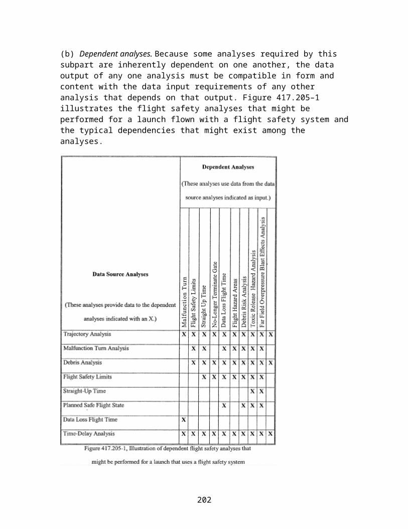
A417.15 Straight-up time
(a) General . A flight safety analysis must include a straight-up time analysis that satisfies the requirements of §417.215. This section applies to the computation of straight-up time as required by §417.215 and to the analysis products that the launch operator must file with the FAA as required by §417.203(e). The analysis must establish a straight-up time as the latest time-after-liftoff, assuming a launch vehicle malfunctioned and flew in a vertical or near vertical direction above the launch point, at which activation of the launch vehicle's flight termination system or breakup of the launch vehicle would not cause hazardous debris or critical overpressure to affect any populated or other protected area.
(b) Straight-up time constraints . A straight-up time analysis must account for the following:
(1) Launch vehicle trajectory. The analysis must use the straight-up trajectory determined as required by section A417.7(e).
(2) Sources of debris impact dispersion. The analysis must use the sources described in section A417.13(b)(3)(iii) through (xii).
(c) Straight-up time analysis products . The products of a straight-up-time analysis that a launch operator must file with the FAA include:
(1) The straight-up-time.
(2) A description of the methodology used to determine straight-up time.
A417.17 Overflight gate
(a) General . The flight safety analysis for a launch that involves flight over a populated or other protected area must include an overflight gate analysis that satisfies the requirements of §417.217. This section applies to determining a gate as required by §417.217 and the analysis products that the launch operator must file with the FAA as required by §417.203(e). The analysis must determine the portion, referred to as a gate, of a flight safety limit, through which a launch vehicle's tracking representation will be allowed to proceed without flight termination.
(b) Overflight gate analysis constraints . The following analysis constraints apply to a gate analysis.
(1) For each gate in a flight safety limit, all the criteria used for determining whether to allow passage through the gate or to terminate flight at the gate must use all the same launch vehicle flight status parameters as the criteria used for determining whether to terminate flight at a flight safety limit. For example, if the flight safety limits are a function of instantaneous impact point location, the criteria for determining whether to
202

allow passage through a gate in the flight safety limit must also be a function of instantaneous impact point location. Likewise, if the flight safety limits are a function of drag impact point, the gate criteria must also be a function of drag impact point.
(2) When establishing a gate in a flight safety limit, the analysis must ensure that the launch vehicle flight satisfies the flight safety requirements of §417.107.
(3) For each established gate, the analysis must account for:
(i) All launch vehicle tracking and map errors.
(ii) All launch vehicle plus and minus three-sigma trajectory limits.
(iii) All debris impact dispersions.
(4) The width of a gate must restrict a launch vehicle's normal trajectory ground trace.
(c) Overflight gate analysis products . The products of a gate analysis that a launch operator must file with the FAA include:
(1) A description of the methodology used to establish each gate.
(2) A description of the tracking representation.
(3) A tabular description of the input data.
(4) Example analysis computations performed to determine a gate. If a launch involves more than one gate and the same methodology is used to determine each gate, the launch operator need only file the computations for one of the gates.
(5) A graphic depiction of each gate. A launch operator must provide a depiction or depictions showing flight safety limits, protected area outlines, nominal and 3-sigma left and right trajectory ground traces, protected area overflight regions, and predicted impact dispersion about the three-sigma trajectories within the gate. Each depiction must show latitude and longitude grid lines, gate latitude and longitude labels, and the map scale.
A417.19 Data loss flight time and planned safe flight state
(a) General . A flight safety analysis must include a data loss flight time analysis that satisfies the requirements of §417.219. This section applies to the computation of data loss flight times and the planned safe flight state required by §417.219, and to the analysis products that the launch operator must file with the FAA as required by §417.203(e).
(b) Planned safe flight state . The analysis must establish a planned safe flight state for a launch as follows:
203
(1) For a suborbital launch, the analysis must determine a planned safe flight state as the nominal state vector after liftoff that a launch vehicle's hazardous debris impact dispersion can no longer reach any protected area.
(2) For an orbital launch where the launch vehicle's instantaneous impact point does not traverse a protected area prior to reaching orbit, the analysis must establish the planned safe flight state as the time after liftoff that the launch vehicle's hazardous debris impact dispersion can no longer reach any protected area or orbital insertion, whichever occurs first.
(3) For an orbital launch where a gate permits overflight of a protected area and where orbital insertion occurs after reaching the gate, the analysis must determine the planned safe flight state as the time after liftoff when the time for the launch vehicle's instantaneous impact point to reach the gate is less than the time for the instantaneous impact point to reach any flight safety limit.
(4) The analysis must account for a malfunction that causes the launch vehicle to proceed from its position at the trajectory time being evaluated toward the closest flight safety limit and protected area.
(5) The analysis must account for the launch vehicle thrust vector that produces the highest instantaneous impact point range rate that the vehicle is capable of producing at the trajectory time being evaluated.
(c) Data loss flight times. For each launch vehicle trajectory time, from the predicted earliest launch vehicle tracking acquisition time until the planned safe flight state, the analysis must determine the data loss flight time as follows:
(1) The analysis must determine each data loss flight time as the minimum thrusting time for a launch vehicle to move from a normal trajectory position to a position where a flight termination would cause the malfunction debris impact dispersion to reach any protected area.
(2) A data loss flight time analysis must account for a malfunction that causes the launch vehicle to proceed from its position at the trajectory time being evaluated toward the closest flight safety limit and protected area.
(3) The analysis must account for the launch vehicle thrust vector that produces the highest instantaneous impact point range rate that the vehicle is capable of producing at the trajectory time being evaluated.
(4) Each data loss flight time must account for the system delays at the time of flight.
(5) The analysis must determine a data loss flight time for time increments that do not exceed one second along the launch vehicle nominal trajectory.
204

(d) Products. The products of a data loss flight time and planned safe flight state analysis that a launch operator must file include:
(1) A launch operator must describe the methodology used in its analysis, and identify all assumptions, techniques, input data, and equations used. A launch operator must file calculations performed for one data loss flight time in the vicinity of the launch site and one data loss flight time that is no less than 50 seconds later in the downrange area.
(2) A launch operator must file a graphical description or depictions of the flight safety limits, the launch point, the launch site boundaries, the surrounding geographic area, any protected areas, the planned safe flight state within any applicable scale requirements, latitude and longitude grid lines, and launch vehicle nominal and three-sigma instantaneous impact point ground traces from liftoff through orbital insertion for an orbital launch, and through final impact for a suborbital launch. Each graph must show any launch vehicle trajectory instantaneous impact points plotted with sufficient frequency to provide a conformal estimate of the launch vehicle's instantaneous impact point ground trace curvature. A launch operator must provide labeled latitude and longitude lines and the map scale on the depiction.
(3) A launch operator must provide a tabular description of each data loss flight time. The tabular description must include the malfunction start time and the geodetic latitude (positive north of the equator) and longitude (positive east of the Greenwich Meridian) coordinates of the intersection of the launch vehicle instantaneous impact point trajectory with the flight safety limit. The table must identify the first data lost flight time and planned safe flight state. The tabular description must include data loss flight times for trajectory time increments not to exceed one second.
A417.21 Time delay
(a) General. A flight safety analysis must include a time delay analysis that satisfies the requirements of §417.221. This section applies to the computation of time delays associated with a flight safety system and other launch vehicle systems and operations as required by §417.221 and to the analysis products that the launch operator must file with the FAA as required by §417.203(e).
(b) Time delay analysis constraints. The analysis must account for all significant causes of time delay between the violation of a flight termination rule and the time when a flight safety system is capable of terminating flight as follows:
(1) The analysis must account for decision and reaction times, including variation in human response time, for flight safety official and other personnel that are part of a launch operator's flight safety system as defined by subpart D of this part.
(2) The analyses must determine the time delay inherent in any data, from any source, used by a flight safety official for making flight termination decisions.
205

(3) A time delay analysis must account for all significant causes of time delay, including data flow rates and reaction times, for hardware and software, including, but not limited to the following:
(i) Tracking system. A time delay analysis must account for time delays between the launch vehicle's current location and last known location and that are associated with the hardware and software that make up the launch vehicle tracking system, whether or not it is located on the launch vehicle, such as transmitters, receivers, decoders, encoders, modulators, circuitry and any encryption and decryption of data.
(ii) Display systems. A time delay analysis must account for delays associated with hardware and software that make up any display system used by a flight safety official to aid in making flight control decisions. A time delay analysis must also account for any manual operations requirements, tracking source selection, tracking data processing, flight safety limit computations, inherent display delays, meteorological data processing, automated or manual system configuration control, automated or manual process control, automated or manual mission discrete control, and automated or manual fail over decision control.
(iii) Flight termination system and command control system. A time delay analysis must account for delays and response times associated with flight termination system and command control system hardware and software, such as transmitters, decoders, encoders, modulators, relays and shutdown, arming and destruct devices, circuitry and any encryption and decryption of data.
(iv) Software specific time delays. A delay analysis must account for delays associated with any correlation of data performed by software, such as timing and sequencing; data filtering delays such as error correction, smoothing, editing, or tracking source selection; data transformation delays; and computation cycle time.
(4) A time delay analysis must determine the time delay plus and minus three-sigma values relative to the mean time delay.
(5) For use in any risk analysis, a time delay analysis must determine time delay distributions that account for the variance of time delays for potential launch vehicle failure, including but not limited to, the range of malfunction turn characteristics and the time of flight when the malfunction occurs.
(c) Time delay analysis products. The products of a time delay analysis that a launch operator must file include:
(1) A description of the methodology used to produce the time delay analysis.
(2) A schematic drawing that maps the flight safety official's data flow time delays from the start of a launch vehicle malfunction through the final commanded flight termination on the launch vehicle, including the flight safety official's decision and reaction time. The
206

drawings must indicate major systems, subsystems, major software functions, and data routing.
(3) A tabular listing of each time delay source and its individual mean and plus and minus three-sigma contribution to the overall time delay. The table must provide all time delay values in milliseconds.
(4) The mean delay time and the plus and minus three-sigma values of the delay time relative to the mean value.
A417.23 Flight hazard areas
(a) General. A flight safety analysis must include a flight hazard area analysis that satisfies the requirements of §417.223. This section applies to the determination of flight hazard areas for orbital and suborbital launch vehicles that use a flight termination system to protect the public as required by §417.223 and to the analysis products that the launch operator must file with the FAA as required by §417.203(e). Requirements that apply to determining flight hazard areas for an unguided suborbital rocket that uses a wind-weighting safety system are contained in appendix C of this part.
(b) Launch site flight hazard area. A flight hazard area analysis must establish a launch site flight hazard area that encompasses the launch point and:
(1) If the flight safety analysis employs hazard isolation to establish flight safety limits as required by section A417.13(c), the launch site flight hazard area must encompass the flight safety limits.
(2) If the flight safety analysis does not employ hazard isolation to establish the flight safety limits, the launch site flight hazard area must encompass all hazard areas established as required by paragraphs (c) through (e) of this section.
(c) Debris impact hazard area. The analysis must establish a debris impact hazard area that accounts for the effects of impacting debris resulting from normal and malfunctioning launch vehicle flight, except for toxic effects, and accounts for potential impact locations of all debris fragments. The analysis must establish a debris hazard area as follows:
(1) An individual casualty contour that defines where the risk to an individual would exceed an expected casualty (Ec) criteria of 1 x 10 −6 if one person were assumed to be in the open and inside the contour during launch vehicle flight must bound a debris hazard area. The analysis must produce an individual casualty contour as follows:
(i) The analysis must account for the location of a hypothetical person, and must vary the location of the person to determine when the risk would exceed the Ec criteria of 1 x 10 −6. The analysis must count a person as a casualty when the person's location is subjected to any inert debris impact with a mean expected kinetic energy greater than or equal to 11
207

ft-lbs or a peak incident overpressure equal to or greater than 1.0 psi due to explosive debris impact. The analysis must determine the peak incident overpressure using the Kingery-Bulmash relationship, without regard to sheltering, reflections, or atmospheric effects.
(ii) The analysis must account for person locations that are no more than 1000 feet apart in the downrange direction and no more than 1000 feet apart in the crossrange direction to produce an individual casualty contour. For each person location, the analysis must sum the probabilities of casualty over all flight times for all debris groups.
(iii) An individual casualty contour must consist of curves that are smooth and continuous. To accomplish this, the analysis must vary the time interval between the trajectory times assessed so that each location of a debris impact point is less than one-half sigma of the downrange dispersion distance.
(2) The input for determining a debris impact hazard area must account for the results of the trajectory analysis required by section A417.7, the malfunction turn analysis required by section A417.9, and the debris analysis required by section A417.11 to define the impact locations of each class of debris established by the debris analysis, and the time delay analysis required by section A417.21.
(3) The analysis must account for the extent of the impact debris dispersions for each debris class produced by normal and malfunctioning launch vehicle flight at each trajectory time. The analysis must also account for how the vehicle breaks up, either by the flight termination system or by aerodynamic forces, if the different breakup may result in a different probability of existence for each debris class. A debris impact hazard area must account for each impacting debris fragment classified as required by section A417.11(c).
(4) The analysis must account for launch vehicle flight that exceeds a flight safety limit. The analysis must also account for trajectory conditions that maximize the mean debris impact distance during the flight safety system delay time determined as required by section A417.21 and account for a debris model that is representative of a flight termination or aerodynamic breakup. For each launch vehicle breakup event, the analysis must account for trajectory and breakup dispersions, variations in debris class characteristics, and debris dispersion due to any wind condition under which a launch would be attempted.
(5) The analysis must account for the probability of failure of each launch vehicle stage and the probability of existence of each debris class. The analysis must account for the probability of occurrence of each type of launch vehicle failure. The analysis must account for vehicle failure probabilities that vary depending on the time of flight.
(6) In addition to failure debris, the analysis must account for nominal jettisoned body debris impacts and the corresponding debris impact dispersions. The analysis must use a
208

probability of occurrence of 1.0 for the planned debris fragments produced by normal separation events during flight.
(d) Near-launch-point blast hazard area. A flight hazard area analysis must define a blast overpressure hazard area as a circle extending from the launch point with a radius equal to the 1.0 psi overpressure distance produced by the equivalent TNT weight of the explosive capability of the vehicle. In addition, the analysis must establish a minimum near-pad blast hazard area to provide protection from hazardous fragments potentially propelled by an explosion. The analysis must account for the maximum possible total solid and liquid propellant explosive potential of the launch vehicle and any payload. The analysis must define a blast overpressure hazard area using the following equations:
Rop= 45 · (NEW)1/3
Where:
Ropis the over pressure distance in feet.
NEW = WE· C (pounds).
WEis the weight of the explosive in pounds.
C is the TNT equivalency coefficient of the propellant being evaluated. A launch operator must identify the TNT equivalency of each propellant on its launch vehicle including any payload. TNT equivalency data for common liquid propellants is provided in tables A417–1. Table A417–2 provides factors for converting gallons of specified liquid propellants to pounds.
(e) Other hazards. A flight hazard area analysis must identify any additional hazards, such as radioactive material, that may exist on the launch vehicle or payload. For each such hazard, the analysis must determine a hazard area that encompasses any debris impact point and its dispersion and includes an additional hazard radius that accounts for potential casualty due to the additional hazard. Analysis requirements for toxic release and far field blast overpressure are provided in §417.27 and section A417.29, respectively.
(1) Aircraft hazard areas. The analysis must establish an aircraft hazard area for each planned debris impact for the issuance of notices to airmen as required by §417.121(e). Each aircraft hazard area must encompass an air space region, from an altitude of 60,000 feet to impact on the Earth's surface, that contains the three-sigma drag impact dispersion.
(2) Ship hazard areas. The analysis must establish a ship hazard area for each planned debris impact for the issuance of notices to mariners as required by §417.121(e). Each ship hazard area must encompass a surface region that contains the three-sigma drag impact dispersion.
209

(f) Flight hazard area analysis products. The products of a flight hazard area analysis that a launch operator must file with the FAA include:
(1) A chart that depicts the launch site flight hazard area, including its size and location.
(2) A chart that depicts each hazard area required by this section.
(3) A description of each hazard for which analysis was performed; the methodology used to compute each hazard area; and the debris classes for aerodynamic breakup of the launch vehicle and for flight termination. For each debris class, the launch operator must identify the number of debris fragments, the variation in ballistic coefficient, and the standard deviation of the debris dispersion.
(4) A chart that depicts each of the individual casualty contour.
(5) A description of the aircraft hazard area for each planned debris impact, the information to be published in a Notice to Airmen, and all information required as part of any agreement with the FAA ATC office having jurisdiction over the airspace through which flight will take place.
(6) A description of any ship hazard area for each planned debris impact and all information required in a Notice to Mariners.
(7) A description of the methodology used for determining each hazard area.
(8) A description of the hazard area operational controls and procedures to be implemented for flight.
210
A417.25 Debris risk
(a) General. A flight safety analysis must include a debris risk analysis that satisfies the requirements of §417.225. This section applies to the computation of the average number of casualties (Ec) to the collective members of debris hazards from the proposed flight of a launch vehicle as required by §417.225 and to the analysis products that the launch operator must file with the FAA as required by §417.203(e).
(b) Debris risk analysis constraints. The following constraints apply to a debris risk:
(1) A debris risk analysis must use valid risk analysis models that compute Ecas the summation over all trajectory time intervals from lift-off through orbital insertion of the products of the probability of each possible event and the casualty consequences due to debris impacts for each possible event.
(2) A debris risk analysis must account for the following populations:
(i) The overflight of populations located inside any flight safety limits.
(ii) All populations located within five-sigma left and right crossrange of a nominal trajectory instantaneous impact point ground trace and within five-sigma of each planned nominal debris impact.
(iii) Any planned overflight of the public within any gate overflight areas.
(iv) Any populations outside the flight safety limits identified as required by paragraph (b)(10) of this section.
(3) A debris risk analysis must account for both inert and explosive debris hazards produced from any impacting debris caused by normal and malfunctioning launch vehicle flight. The analysis must account for the debris classes determined by the debris analysis required by section A417.11. A debris risk analysis must account for any inert debris impact with mean expected kinetic energy at impact greater than or equal to 11 ft-lbs and
211

peak incident overpressure of greater than or equal to 1.0 psi due to any explosive debris impact. The analysis must account for all debris hazards as a function of flight time.
(4) A debris risk analysis must account for debris impact points and dispersion for each class of debris as follows:
(i) A debris risk analysis must account for drag corrected impact points and dispersions for each class of impacting debris resulting from normal and malfunctioning launch vehicle flight as a function of trajectory time from lift-off through orbital insertion, including each planned impact, for an orbital launch, and through final impact for a suborbital launch.
(ii) The dispersion for each debris class must account for the position and velocity state vector dispersions at breakup, the variance produced by breakup imparted velocities, the effect of winds on both the ascent trajectory state vector at breakup and the descending debris piece impact location the variance produced by aerodynamic properties for each debris class, and any other dispersion variances.
(iii) A debris risk analysis must account for the survivability of debris fragments that are subject to reentry aerodynamic forces or heating. A debris class may be eliminated from the debris risk analysis if the launch operator demonstrates that the debris will not survive to impact.
(5) A debris risk analysis must account for launch vehicle failure probability. The following constraints apply:
(i) For flight safety analysis purposes, a failure occurs when a vehicle does not complete any phase of normal flight or exhibits the potential for the stage or its debris to impact the Earth or reenter the atmosphere during the mission or any future mission of similar vehicle capability. Also, either a launch incident or launch accident constitutes a failure.
(ii) For a launch vehicle with fewer than 2 flights completed, the analysis must use a reference value for the launch vehicle failure probability estimate equal to the upper limit of the 60% two-sided confidence limits of the binomial distribution for outcomes of all previous launches of vehicles developed and launched in similar circumstances. The FAA may adjust the failure probability estimate to account for the level of experience demonstrated by the launch operator and other factors that affects the probability of failure. The FAA may adjust the failure probability estimate for the second launch based on evidence obtained from the first flight of the vehicle.
(iii) For a launch vehicle with at least 2 flights completed, the analysis must use the reference value for the launch vehicle failure probability of Table A417–3 based on the outcomes of all previous launches of the vehicle. The FAA may adjust the failure probability estimate to account for evidence obtained from the flight history of the vehicle. The FAA may adjust the failure probability estimate to account for the nature of launch outcomes in the flight history of the vehicle, corrective actions taken in response
212

to a failure of the vehicle, or other vehicle modifications that may affect reliability. The FAA may adjust the failure probability estimate to account for the demonstrated quality of the engineering approach to launch vehicle processing, meeting safety requirements in this part, and associated hazard mitigation. The analysis must use a final failure estimate within the confidence limits of Table A417–3.
(A) Values listed on the far left of Table A417–3 apply when no launch failures are experienced. Values on the far right apply when only launch failures are experienced. Values in between apply for flight histories that include both failures and successes.
(B) Reference values in Table A417–3 are shown in bold. The reference values are the median values between 60% two-sided confidence limits of the binomial distribution. For the special cases of zero or N failures in N launch attempts, the reference values may also be recognized as the median value between the 80% one-sided confidence limit of the binomial distribution and zero or one, respectively.
(C) Upper and lower confidence bounds in Table A417–3 are shown directly above and below each reference value. These confidence bounds are based on 60% two-sided confidence limits of the binomial distribution. For the special cases of zero or N failures in N launch attempts, the upper and lower confidence bounds are based on the 80% one-sided confidence limit, respectively.
213

(6) A debris risk analysis must account for the dwell time of the instantaneous impact point ground trace over each populated or protected area being evaluated.
(7) A debris risk analysis must account for the three-sigma instantaneous impact point trajectory variations in left-crossrange, right-crossrange, uprange, and downrange as a function of trajectory time, due to launch vehicle performance variations as determined by the trajectory analysis performed as required by section A417.7.
(8) A debris risk analysis must account for the effective casualty area as a function of launch vehicle flight time for all impacting debris generated from a catastrophic launch
214

vehicle malfunction event or a planned impact event. The effective casualty area must account for both payload and vehicle systems and subsystems debris. The effective casualty area must account for all debris fragments determined as part of a launch operator's debris analysis as required by section A417.11. The effective casualty area for each explosive debris fragment must account for a 1.0 psi blast overpressure radius and the projected debris effects for all potentially explosive debris. The effective casualty area for each inert debris fragment must:
(i) Account for bounce, skip, slide, and splatter effects; or
(ii) Equal seven times the maximum projected area of the fragment.
(9) A debris risk analysis must account for current population density data obtained from a current population database for the region being evaluated or by estimating the current population using exponential population growth rate equations applied to the most current historical data available. The population model must define population centers that are similar enough to be described and treated as a single average set of characteristics without degrading the accuracy of the debris risk estimate.
(10) For a launch vehicle that uses a flight safety system, a debris risk analysis must account for the collective risk to any populations outside the flight safety limits during flight, including people who will be at any public launch viewing area during flight. For such populations, in addition to the constraints of paragraphs (b)(1) through (b)(9) of this section, a launch operator's debris risk analysis must account for the following:
(i) The probability of a launch vehicle failure that would result in debris impact in protected areas outside the flight safety limits.
(ii) The failure probability of the launch operator's flight safety system. A flight safety system failure rate of 0.002 may be used if the flight safety system complies with the flight safety system requirements of subpart D of this part. For an alternate flight safety system approved as required by §417.107(a)(3), the launch operator must demonstrate the validity of the probability of failure through the licensing process.
(iii) Current population density data and population projections for the day and time of flight for the areas outside the flight safety limits.
(c) Debris risk analysis products. The products of a debris risk analysis that a launch operator must file with the FAA include:
(1) A debris risk analysis report that provides the analysis input data, probabilistic risk determination methods, sample computations, and text or graphical charts that characterize the public risk to geographical areas for each launch.
(2) Geographic data showing:
215
(i) The launch vehicle nominal, five-sigma left-crossrange and five-sigma right-crossrange instantaneous impact point ground traces;
(ii) All exclusion zones relative to the instantaneous impact point ground traces; and
(iii) All populated areas included in the debris risk analysis.
(3) A discussion of each launch vehicle failure scenario accounted for in the analysis and the probability of occurrence, which may vary with flight time, for each failure scenario. This information must include failure scenarios where a launch vehicle:
(i) Flies within normal limits until some malfunction causes spontaneous breakup or results in a commanded flight termination;
(ii) Experiences malfunction turns; and
(iii) Flight safety system fails to function.
(4) A population model applicable to the launch overflight regions that contains the following: region identification, location of the center of each population center by geodetic latitude and longitude, total area, number of persons in each population center, and a description of the shelter characteristics within the population center.
(5) A description of the launch vehicle, including general information concerning the nature and purpose of the launch and an overview of the launch vehicle, including a scaled diagram of the general arrangement and dimensions of the vehicle. A launch operator's debris risk analysis products may reference other documentation filed with the FAA containing this information. The description must include:
(i) Weights and dimensions of each stage.
(ii) Weights and dimensions of any booster motors attached.
(iii) The types of fuel used in each stage and booster.
(iv) Weights and dimensions of all interstage adapters and skirts.
(v) Payload dimensions, materials, construction, and any payload fuel; payload fairing construction, materials, and dimensions; and any non-inert components or materials that add to the effective casualty area of the debris, such as radioactive or toxic materials or high-pressure vessels.
(6) A typical sequence of events showing times of ignition, cutoff, burnout, and jettison of each stage, firing of any ullage rockets, and starting and ending times of coast periods and control modes.
216

(7) The following information for each launch vehicle motor:
(i) Propellant type and composition;
(ii) Thrust profile;
(iii) Propellant weight and total motor weight as a function of time;
(iv) A description of each nozzle and steering mechanism;
(v) For solid rocket motors, internal pressure and average propellant thickness, or borehole radius, as a function of time;
(vi) Maximum impact point deviations as a function of failure time during destruct system delays. Burn rate as a function of ambient pressure;
(vii) A discussion of whether a commanded destruct could ignite a non-thrusting motor, and if so, under what conditions; and
(viii) Nozzle exit and entrance areas.
(8) The launch vehicle's launch and failure history, including a summary of past vehicle performance. For a new vehicle with little or no flight history, a launch operator must provide all known data on similar vehicles that include:
(i) Identification of the launches that have occurred;
(ii) Launch date, location, and direction of each launch;
(iii) The number of launches that performed normally;
(iv) Behavior and impact location of each abnormal experience;
(v) The time, altitude, and nature of each malfunction; and
(vi) Descriptions of corrective actions taken, including changes in vehicle design, flight termination, and guidance and control hardware and software.
(9) The values of probability of impact (PI) and expected casualty (Ec) for each populated area.
A417.27 Toxic release hazard analysis
A flight safety analysis must include a toxic release hazard analysis that satisfies the requirements of §417.227. A launch operator's toxic release hazard analysis must satisfy
217

the methodology requirements of appendix I of this part. A launch operator must file the analysis products identified in appendix I of this part as required by §417.203(e).
A417.29 Far field blast overpressure effects analysis
(a) General. A flight safety analysis must include a far field blast overpressure effects hazard analysis that satisfies the requirements of §417.229. This section applies to the computation of far field blast overpressure effects from the proposed flight of a launch vehicle as required by §417.229 and to the analysis products that the launch operator must file with the FAA as required by §417.203(e). The analysis must account for distant focus overpressure and any overpressure enhancement to establish the potential for broken windows due to peak incident overpressures below 1.0 psi and related casualties due to falling or projected glass shards. The analysis must employ either paragraph (b) of this section or the risk analysis of paragraph (c) of this section.
(b) Far field blast overpressure hazard analysis. Unless an analysis satisfies the requirements of paragraph (c) of this section a far field blast overpressure hazard analysis must satisfy the following:
(1) Explosive yield factors. The analysis must use explosive yield factor curves for each type or class of solid or liquid propellant used by the launch vehicle. Each explosive yield factor curve must be based on the most accurate explosive yield data for the corresponding type or class of solid or liquid propellant based on empirical data or computational modeling.
(2) Establish the maximum credible explosive yield. The analysis must establish the maximum credible explosive yield resulting from normal and malfunctioning launch vehicle flight. The explosive yield must account for impact mass and velocity of impact on the Earth's surface. The analysis must account for explosive yield expressed as a TNT equivalent for peak overpressure.
(3) Characterize the population exposed to the hazard. The analysis must demonstrate whether any population centers are vulnerable to a distant focus overpressure hazard using the methodology provided by section 6.3.2.4 of the American National Standard Institute's ANSI S2.20–1983, “Estimating Air Blast Characteristics for Single Point Explosions in Air with a Guide to Evaluation of Atmospheric Propagation and Effects” and as follows:
(i) For the purposes of this analysis, a population center must include any area outside the launch site and not under the launch operator's control that contains an exposed site. An exposed site includes any structure that may be occupied by human beings, and that has at least one window, but does not include automobiles, airplanes, and waterborne vessels. The analysis must account for the most recent census information on each population center. The analysis must treat any exposed site for which no census information is available, or the census information indicates a population equal to or less than four persons, as a ‘single residence.'
218
(ii) The analysis must identify the distance between the location of the maximum credible impact explosion and the location of each population center potentially exposed. Unless the location of the potential explosion site is limited to a defined region, the analysis must account for the distance between the potential explosion site and a population center as the minimum distance between any point within the region contained by the flight safety limits and the nearest exposed site within the population center.
(iii) The analysis must account for all weather conditions optimized for a distant focus overpressure hazard by applying an atmospheric blast “focus factor” (F) of 5.
(iv) The analysis must determine, using the methodology of section 6.3.2.4 of ANSI S2.20–1983, for each a population center, whether the maximum credible explosive yield of a launch meets, exceeds or is less than the “no damage yield limit,” of the population center. If the maximum credible explosive yield is less than the “no damage yield limit” for all exposed sites, the remaining requirements of this section do not apply. If the maximum credible explosive yield meets or exceeds the “no damage yield limit” for a population center then that population center is vulnerable to far field blast overpressure from the launch and the requirements of paragraphs (b)(4) and (b)(5) of this section apply.
(4) Estimate the quantity of broken windows. The analysis must use a focus factor of 5 and the methods provided by ANSI S2.20–1983 to estimate the number of potential broken windows within each population center determined to be vulnerable to the distant focus overpressure hazard as required by paragraph (b)(3) of this section.
(5) Determine and implement measures necessary to prevent distant focus overpressure from breaking windows. For each population center that is vulnerable to far field blast overpressure from a launch, the analysis must identify mitigation measures to protect the public from serious injury from broken windows and the flight commit criteria of §417.113(b) needed to enforce the mitigation measures. A launch operator's mitigation measures must include one or more of the following:
(i) Apply a minimum 4-millimeter thick anti-shatter film to all exposed sites where the maximum credible yield exceeds the “no damage yield limit.”
(ii) Evacuate the exposed public to a location that is not vulnerable to the distant focus overpressure hazard at least two hours prior to the planned flight time.
(iii) If, as required by paragraph (b)(4) of this section, the analysis predicts that less than 20 windows will break, advise the public of the potential for glass breakage.
(c) Far field blast overpressure risk analysis. If a launch operator does not employ paragraph (b) of this section to perform a far field overpressure hazard analysis, the launch operator must conduct a risk analysis that demonstrates that the launch will be conducted in accordance with the public risk criteria of §417.107(b).
219
(d) Far field blast overpressure effect products. The products of a far field blast overpressure analysis that a launch operator must file with the FAA include:
(1) A description of the methodology used to produce the far field blast overpressure analysis results, a tabular description of the analysis input data, and a description of any far field blast overpressure mitigation measures implemented.
(2) For any far field blast overpressure risk analysis, an example set of the analysis computations.
(3) The values for the maximum credible explosive yield as a function of time of flight.
(4) The distance between the potential explosion location and any population center vulnerable to the far field blast overpressure hazard. For each population center, the launch operator must identify the exposed populations by location and number of people.
(5) Any mitigation measures established to protect the public from far field blast overpressure hazards and any flight commit criteria established to ensure the mitigation measures are enforced.
A417.31 Collision avoidance
(a) General. A flight safety analysis must include a collision avoidance analysis that satisfies the requirements of §417.231. This section applies to a launch operator obtaining a collision avoidance assessment from United States Strategic Command as required by §417.231 and to the analysis products that the launch operator must file with the FAA as required by §417.203(e). United States Strategic Command refers to a collision avoidance analysis for a space launch as a conjunction on launch assessment.
(b) Analysis constraints. A launch operator must satisfy the following when obtaining and implementing the results of a collision avoidance analysis:
(1) A launch operator must provide United States Strategic Command with the launch window and trajectory data needed to perform a collision avoidance analysis for a launch as required by paragraph (c) of this section, at least 15 days before the first attempt at flight. The FAA will identify a launch operator to United States Strategic Command as part of issuing a license and provide a launch operator with current United States Strategic Command contact information.
(2) A launch operator must obtain a collision avoidance analysis performed by United States Strategic Command 6 hours before the beginning of a launch window.
(3) A launch operator may use a collision avoidance analysis for 12 hours from the time that United States Strategic Command determines the state vectors of the manned or mannable orbiting objects. If a launch operator needs an updated collision avoidance analysis due to a launch delay, the launch operator must file the request with United
220

States Strategic Command at least 12 hours prior to the beginning of the new launch window.
(4) For every 90 minutes, or portion of 90 minutes, that pass between the time United States Strategic Command last determined the state vectors of the orbiting objects, a launch operator must expand each wait in a launch window by subtracting 15 seconds from the start of the wait in the launch window and adding 15 seconds to the end of the wait in the launch window. A launch operator must incorporate all the resulting waits in the launch window into its flight commit criteria established as required by §417.113.
(c) Information required. A launch operator must prepare a collision avoidance analysis worksheet for each launch using a standardized format that contains the input data required by this paragraph. A launch operator must file the input data with United States Strategic Command for the purposes of completing a collision avoidance analysis. A launch operator must file the input data with the FAA as part of the license application process as required by §415.115 of this chapter.
(1) Launch information. A launch operator must file the following launch information:
(i) Mission name. A mnemonic given to the launch vehicle/payload combination identifying the launch mission from all others.
(ii) Segment number. A segment is defined as a launch vehicle stage or payload after the thrusting portion of its flight has ended. This includes the jettison or deployment of any stage or payload. A launch operator must provide a separate worksheet for each segment. For each segment, a launch operator must determine the “vector at injection” as defined by paragraph (c)(5) of this section. The data must present each segment number as a sequence number relative to the total number of segments for a launch, such as “1 of 5.”
(iii) Launch window. The launch window opening and closing times in Greenwich Mean Time (referred to as ZULU time) and the Julian dates for each scheduled launch attempt.
(2) Point of contact. The person or office within a launch operator's organization that collects, analyzes, and distributes collision avoidance analysis results.
(3) Collision avoidance analysis analysis results transmission medium. A launch operator must identify the transmission medium, such as voice, FAX, or e-mail, for receiving results from United States Strategic Command.
(4) Requestor launch operator needs. A launch operator must indicate the types of analysis output formats required for establishing flight commit criteria for a launch:
(i) Waits. All the times within the launch window during which flight must not be initiated.
221
(ii) Windows. All the times within an overall launch window during which flight may be initiated.
(5) Vector at injection. A launch operator must identify the vector at injection for each segment. “Vector at injection” identifies the position and velocity of all orbital or suborbital segments after the thrust for a segment has ended.
(i) Epoch. The epoch time, in Greenwich Mean Time (GMT), of the expected launch vehicle liftoff time.
(ii) Position and velocity. The position coordinates in the EFG coordinate system measured in kilometers and the EFG components measured in kilometers per second, of each launch vehicle stage or payload after any burnout, jettison, or deployment.
(6) Time of powered flight. The elapsed time in seconds, from liftoff to arrival at the launch vehicle vector at injection. The input data must include the time of powered flight for each stage or jettisoned component measured from liftoff.
(7) Time span for launch window file (LWF). A launch operator must provide the following information regarding its launch window:
(i) Launch window. The launch window measured in minutes from the initial proposed liftoff time.
(ii) Time of powered flight. The time provided as required by paragraph (c)(6) of this section measured in minutes rounded up to the nearest integer minute.
(iii) Screen duration. The time duration, after all thrusting periods of flight have ended, that a collision avoidance analysis must screen for potential conjunctions with manned or mannable orbital objects. Screen duration is measured in minutes and must be greater than or equal to 100 minutes for an orbital launch.
(iv) Extra pad. An additional period of time for collision avoidance analysis screening to ensure the entire first orbit is screened for potential conjunctions with manned or mannable orbital objects. This time must be 10 minutes unless otherwise specified by United States Strategic Command.
(v) Total. The summation total of the time spans provided as required by paragraphs (c)(7)(i) through (c)(7)(iv) expressed in minutes.
(8) Screening. A launch operator must select spherical or ellipsoidal screening as defined in this paragraph for determining any conjunction. The default must be the spherical screening method using an avoidance radius of 200 kilometers for manned or mannable orbiting objects. If the launch operator requests screening for any unmanned or unmannable objects, the default must be the spherical screening method using a miss distance of 25 kilometers.
222
(i) Spherical screening. Spherical screening utilizes an impact exclusion sphere centered on each orbiting object's center-of-mass to determine any conjunction. A launch operator must specify the avoidance radius for manned or mannable objects and for any unmanned or unmannable objects if the launch operator elects to perform the analysis for unmanned or unmannable objects.
(ii) Ellipsoidal screening. Ellipsoidal screening utilizes an impact exclusion ellipsoid of revolution centered on the orbiting object's center-of-mass to determine any conjunction. A launch operator must provide input in the UVW coordinate system in kilometers. The launch operator must provide delta–U measured in the radial-track direction, delta–V measured in the in-track direction, and delta–W measured in the cross-track direction.
(9) Orbiting objects to evaluate. A launch operator must identify the orbiting objects to be included in the analysis.
(10) Deliverable schedule/need dates. A launch operator must identify the times before flight, referred to as “L-times,” for which the launch operator requests a collision avoidance analysis.
(d) Collision avoidance assessment products. A launch operator must file its collision avoidance analysis products as required by §417.203(e) and must include the input data required by paragraph (c) of this section. A launch operator must incorporate the result of the collision avoidance analysis into its flight commit criteria established as required by §417.113.
223

Appendix B to Part 417—Flight Hazard Area Analysis for Aircraft and Ship Protection
B417.1 Scope
This appendix contains requirements to establish aircraft hazard areas, ship hazard areas, and land impact hazard areas. The methodologies contained in this appendix represent an acceptable means of satisfying the requirements of §417.107 and §417.223 as they pertain to ship, aircraft, and land hazard areas. This appendix provides a standard and a measure of fidelity against which the FAA will measure any proposed alternative approaches. Requirements for a launch operator's implementation of a hazard area are contained in §§417.121(e) and (f).
B417.3 Hazard area notifications and surveillance
(a) A launch operator must ensure the following notifications have been made and adhered to at launch:
(1) A Notice to Airmen (NOTAM) must be issued for every aircraft hazard area identified as required by sections B417.5 and B417.7. The NOTAM must be effective no less than thirty minutes prior to flight and effective until no sooner than thirty minutes after the air space volume requested by the NOTAM can no longer be affected by the launch vehicle or its potential hazardous effects.
(2) A Notice to Mariners (NOTMAR) must be issued for every ship hazard area identified as required by sections B417.5 and B417.7. The NOTMAR must be effective no less than thirty minutes prior to flight and effective until no sooner than thirty minutes after the area requested by the NOTMAR can no longer be affected by the launch vehicle or its potential hazardous effects.
(3) All local officials and landowners adjacent to any hazard area must be notified of the flight schedule no less than two days prior to the flight of the launch vehicle.
(b) A launch operator must survey each of the following hazard areas:
(1) Each launch site hazard area;
(2) Each aircraft hazard area in the vicinity of the launch site; and
(3) Each ship hazard area in the vicinity of the launch site.
B417.5 Launch site hazard area
(a) General. A launch operator must perform a launch site hazard area analysis that protects the public, aircraft, and ships from the hazardous activities in the vicinity of the
224

launch site. The launch operator must evacuate and monitor each launch site hazard area to ensure compliance with §§417.107(b)(2) and (b)(3).
(b) Launch site hazard area analysis input. A launch site hazard area must encompass no less than the following:
(1) Each land hazard area in the vicinity of the launch site calculated as required by section B417.13;
(2) Each ship hazard area in the vicinity of the launch site calculated as required by section B417.11(c); and
(3) The aircraft hazard area in the vicinity of the launch site calculated as required by section B417.9(c).
B417.7 Downrange hazard areas
(a) General. A launch operator must perform a downrange hazard area analysis that protects the public, aircraft, and ships from the hazardous activities in the vicinity of each scheduled impact location.
(b) Downrange hazard areas analysis input. A launch hazard area must bound no less than the following:
(1) The aircraft hazard area in the vicinity of each planned impact location calculated as required by section B417.9(d);
(2) The ship hazard area in the vicinity of each planned water impact location calculated as required by section B417.11(d); and
(3) The land hazard area in the vicinity of each planned land impact location calculated as required by section B417.13.
B417.9 Aircraft hazard areas analysis
(a) General. A launch operator must perform an aircraft hazard areas analysis as required by §417.223(b). A launch operator's aircraft hazard areas analysis must determine the aircraft hazard area in the vicinity of the launch site and the aircraft hazard area in the vicinity of each planned impact location as required by this section.
(b) Aircraft hazard areas analysis input. A launch operator must account for the following inputs to determine the aircraft hazard areas:
(1) The trajectory analysis performed as required by section A417.7 or section C417.3; and
225

(2) The debris risk analysis performed as required by section A417.25 or section C417.9.
(c) Methodology for computing an aircraft hazard area in the vicinity of the launch site. An aircraft hazard area analysis must determine an aircraft hazard area that encompasses the launch point from the surface of the Earth to an altitude of 100,000 ft MSL and wholly contains the launch vehicle's normal trajectory plus five nautical miles in every radial direction. A launch operator must calculate an aircraft hazard area in the vicinity of the launch site as follows:
(1) Using the trajectory analysis performed as required by section A417.7 or section C417.3, select all data locations where the vehicle's nominal altitude, or positional component on the z-axis, is less than and equal to 100,000 ft MSL.
(2) From the data locations representing the dispersed trajectories calculated as required by section A417.7(d) or section C417.3(f) and modified to incorporate a 5 nm buffer as required by paragraph (c)(1) of this section for the data locations selected below a nominal altitude of 100,000 ft MSL as required by paragraph (c)(1) of this section, select the location that is the farthest left-hand crossrange, the location that is the farthest right-hand crossrange, the location that is the farthest downrange, and the location that is the farthest uprange.
(3) Construct a box in the xy plane that includes two lines parallel to the azimuth, two lines perpendicular to the azimuth, and contains the four locations selected as required by paragraph (c)(2) of this section.
(4) Extend the box constructed as required by paragraph (c)(3) of this section from the surface of the Earth to an infinite altitude.
(d) Methodology for computing an aircraft hazard area in the vicinity of each planned impact location. A launch operator must determine an aircraft hazard area in the vicinity of each planned impact location from the surface of the Earth to an altitude of 100,000 ft MSL that wholly contains the launch vehicle's calculated impact dispersion with a 5 nm buffer and the normal trajectory. A launch operator must compute an aircraft hazard area in the vicinity of each planned impact location as follows:
(1) The analysis must calculate a three-sigma dispersion ellipse by determining the three-sigma impact limit around a planned impact location.
(2) Taking the three-sigma dispersion ellipse calculated as required by paragraph (d)(1) of this section, plot a co-centric ellipse in the xy plane where the major and minor axes are 10nm longer than the major and minor axes of the three-sigma dispersion ellipse.
(3) Extend the ellipse calculated as required by paragraph (d)(2) of this section from the surface to an infinite altitude.
226
(4) Using the trajectory that predicts the instantaneous impact locations required in section A417.7(g)(7)(xii) or section C417.3(d), find the location on the trajectory where the vehicle's nominal altitude is predicted to be 100,000 ft MSL.
(5) At the trajectory time where the altitude is represented as 100,000 ft MSL, select the corresponding points from the normal trajectory dispersion that are the farthest uprange, downrange, right crossrange, and left crossrange relative to the nominal trajectory.
(6) Construct a box in the xy plane that includes two lines parallel to the azimuth, two lines perpendicular to the azimuth, and contains the points selected as required by paragraph (d)(5) of this section and the nominal impact point.
(7) Extend the box constructed as required by paragraph (d)(6) of this section from the surface of the Earth to an infinite altitude.
(8) Construct a volume, the aircraft hazard area, that encompasses the volumes calculated as required by paragraphs (d)(3) and (d)(7) of this section.
B417.11 Ship hazard areas analysis
(a) General. A flight hazard area analysis must establish ship hazard areas bound by the 1 × 10⁻⁵ship impact contour in the vicinity of the launch site and the vehicle's three-sigma dispersion limit plus a 5 nm buffer in the vicinity of a planned, downrange impact location.
(b) Ship hazard area analysis input. A launch operator must account for the following inputs to determine the ship hazard areas:
(1) The trajectory analysis performed as required by section A417.7 or section C417.3;
(2) For a launch vehicle flown with a flight safety system, the malfunction turn analysis required by section A417.9;
(3) The debris analysis required by section A417.11 or section C417.7 to define the impact locations of each class of debris established by the debris analysis;
(4) For a launch vehicle flown with a flight safety system, the time delay analysis required by section A417.21; and
(5) The debris risk analysis performed as required by section A417.25 or section C417.9.
(c) Methodology for computing ship hazard areas in the vicinity of the launch site. The analysis must establish the ship-hit contours as follows:
(1) A ship-hit contour must account for the size of the largest ship that could be located in the ship hazard area. The analysis must demonstrate that the ship size used represents the
227
largest ship that could be present in the ship hazard area or, if the ship size is unknown, the analysis must use a ship size of 120,000 square feet.
(2) The analysis must first calculate the probability of impacting the reference ship selected as required by paragraph (c)(1) of this section at the location of interest. From the location of interest, move the ship away from the launch location along a single radial until the probability that debris is present at that location multiplied by the probability that a ship is at that location is less than or equal to 1 × 10⁻⁵. When calculating the probability of impacting a ship, an impact occurs when:
(i) The analysis predicts that inert debris will directly impact the vessel with a mean expected kinetic energy at impact greater than or equal to 11 ft-lbs; or
(ii) The analysis predicts the peak incident overpressure at the reference vessel will be greater than or equal to 1.0 psi due to any explosive debris impact.
(3) The analysis must account for:
(i) The variance in winds;
(ii) The aerodynamic properties of the debris;
(iii) The variance in velocity of the debris;
(iv) Guidance and performance errors;
(v) The type of vehicle breakup, either by any flight termination system or by aerodynamic forces that may result in different debris characteristics; and
(vi) Debris impact dispersion resulting from vehicle breakup and the malfunction turn capabilities of the launch vehicle.
(4) Repeat the process outlined in paragraph (c)(2) of this section while varying the radial direction until enough locations are found where the reference ship's probability of impact is less than or equal to 1 × 10⁻⁵such that connecting each location will result in a smooth and continuous contour.
(d) Methodology for computing ship hazard areas in the vicinity of each planned water impact location. A launch operator must compute a ship hazard area in the vicinity of each planned impact location as required by the following:
(1) The analysis must calculate a three-sigma dispersion ellipse by determining the three-sigma impact limit around a planned impact location.
228
(2) Taking the three-sigma dispersion ellipse calculated as required by paragraph (d)(1) of this section, plot a co-centric ellipse in the xy plane where the major and minor axes are 10 nm longer than the major and minor axes of the three-sigma dispersion ellipse.
B417.13 Land hazard areas analysis
(a) General. A flight hazard area analysis must establish land hazard areas in the vicinity of the launch site and land hazard areas in the vicinity of each land impact location to ensure that the probability of a member of the public being struck by debris satisfies the probability threshold of 1 × 10⁻⁶required by §417.107(b) and to determine exclusion areas that may require entry control and surveillance prior to initiation of flight. The analysis must establish a land impact hazard area that accounts for the effects of impacting debris resulting from normal and malfunctioning launch vehicle flight, except for toxic effects, and accounts for potential impact locations of all debris fragments. The land hazard area must encompass all individual casualty contours and the near-launch-point blast hazard area calculated as required by paragraph (c) of this section. A launch operator may initiate flight only if no member of the public is present within the land hazard area.
(b) Land hazard areas analysis input. A land hazard analysis must account for the following inputs to determine the land hazard area:
(1) The trajectory analysis performed as required by section A417.7 or section C417.3;
(2) For a launch vehicle flown with a flight safety system, the malfunction turn analysis required by section A417.9;
(3) The debris analysis required by section A417.11 or section C417.7 to define the impact locations of each class of debris established by the debris analysis;
(4) For a launch vehicle flown with a flight safety system, the time delay analysis required by section A417.21; and
(5) The debris risk analysis performed as required by section A417.25 or section C417.9.
(c) Methodology for computing land hazard areas in the vicinity of the launch site and in the vicinity of each planned land impact location. The analysis must establish a land hazard area as follows:
(1) Each land hazard area must completely encompass all individual casualty contours that define where the risk to an individual would exceed the expected casualty (Ec) criteria of 1 × 10⁻⁶if one person were assumed to be in the open and inside the contour during launch vehicle flight. The analysis must produce an individual casualty contour as follows:
(i) The analysis must account for the location of a hypothetical person, and must vary the location of the person to determine when the risk would exceed the Eccriteria of 1 × 10⁻⁶.
229

The analysis must count a person as a casualty when the person's location is subjected to any inert debris impact with a mean expected kinetic energy greater than or equal to 11 ft-lbs or a peak incident overpressure equal to or greater than 1.0 psi due to explosive debris impact. The analysis must determine the peak incident overpressure using the Kingery-Bulmash relationship, without regard to sheltering, reflections, or atmospheric effects.
(ii) The analysis must account for all person locations that are no more than 1000 feet apart in the downrange direction and no more than 1000 feet apart in the crossrange direction to produce an individual casualty contour. For each person location, the analysis must sum all the probabilities of casualty over all flight times for all debris groups.
(iii) An individual casualty contour must consist of curves that are smooth and continuous. To accomplish this, the analysis must vary the time interval between each trajectory time assessed so that each location of a debris impact point is less than one-half sigma of the downrange dispersion distance.
(2) The input for determining a land impact hazard area must account for the following in order to define the impact locations of each class of debris established by the debris analysis and the time delay analysis required by section A417.21 for a launch vehicle flown with a flight safety system:
(i) The results of the trajectory analysis required by section A417.7 or section C417.3;
(ii) The malfunction turn analysis required by section A417.9 for a launch vehicle flown with a flight safety system; and
(iii) The debris analysis required by section A417.11 or section C417.7.
(3) The analysis must account for the extent of the impact debris dispersions for each debris class produced by normal and malfunctioning launch vehicle flight at each trajectory time. The analysis must also account for how the vehicle breaks up, either by any flight termination system or by aerodynamic forces, if the different breakup may result in a different probability of existence for each debris class. A land impact hazard area must account for each impacting debris fragment classified as required by section A417.11(c) or section C417.7.
(4) For a launch vehicle flown with a flight safety system, the analysis must account for launch vehicle flight that exceeds a flight safety limit. The analysis must also account for trajectory conditions that maximize the mean debris impact distance during the flight safety system delay time determined as required by section A417.21 and account for a debris model that is representative of a flight termination or aerodynamic breakup.
(5) For each launch vehicle breakup event, the analysis must account for trajectory and breakup dispersions, variations in debris class characteristics, and debris dispersion due to any wind condition under which a launch would be attempted.
230

(6) The analysis must account for the probability of failure of each launch vehicle stage and the probability of existence of each debris class. The analysis must account for the probability of occurrence of each type of launch vehicle failure. The analysis must account for each vehicle failure probabilities that vary depending on the time of flight.
(7) In addition to failure debris, the analysis must account for nominal jettisoned body debris impacts and the corresponding debris impact dispersions. The analysis must use a probability of occurrence of 1.0 for the planned debris fragments produced by normal separation events during flight.
(d) Near-launch-point blast hazard area. A land hazard area analysis must define a blast overpressure hazard area as a circle extending from the launch point with a radius equal to the 1.0 psi overpressure distance produced by the equivalent TNT weight of the explosive capability of the vehicle. In addition, the analysis must establish a minimum near-launch point blast hazard area to provide protection from hazardous fragments potentially propelled by an explosion. The analysis must account for the maximum possible total solid and liquid propellant explosive potential of the launch vehicle and any payload. The analysis must define a blast overpressure hazard area using the following equations:
Rop= 45 · (NEW)1/3
Where:
Ropis the over pressure distance in feet.
NEW = WE· C (pounds).
WEis the weight of the explosive in pounds.
C is the TNT equivalency coefficient of the propellant being evaluated. A launch operator must identify the TNT equivalency of each propellant on its launch vehicle including any payload. TNT equivalency data for common liquid propellants is provided in tables A417–1. Table A417–2 provides factors for converting gallons of specified liquid propellants to pounds.
(e) Other hazards . A flight hazard area analysis must identify any additional hazards, such as radioactive material, that may exist on the launch vehicle or payload. For each such hazard, the analysis must determine a hazard area that encompasses any debris impact point and its dispersion and includes an additional hazard radius that accounts for potential casualty due to the additional hazard. Analysis requirements for toxic release and far field blast overpressure are provided in sections A417.27 and A417.29, respectively.
(f) Land impact dispersion ellipses . A land impact hazard area must contain the land impact dispersion ellipse for each planned land impact. A launch operator must compute
231
a land impact dispersion ellipse in the vicinity of each planned land impact location as follows:
(1) The analysis must calculate a one-sigma dispersion ellipse by determining the one-sigma impact limit around a planned impact location.
(2) Taking the one-sigma dispersion ellipse calculated as required by paragraph (f)(1) of this section, plot a co-centric ellipse in the xy plane where the major and minor axes are 10nm longer than the major and minor axes of the one-sigma dispersion ellipse.
232
Appendix C to Part 417—Flight Safety Analysis Methodologies and Products for an Unguided Suborbital Launch Vehicle Flown With a Wind Weighting Safety System
C417.1 General
(a) This appendix contains methodologies for performing the flight safety analysis required for the launch of an unguided suborbital launch vehicle flown with a wind weighting safety system, except for the hazard area analysis required by §417.107, which is covered in appendix B of this part. This appendix includes methodologies for a trajectory analysis, wind weighting analysis, debris analysis, debris risk analysis, and a collision avoidance analysis.
(b) The requirements of this appendix apply to a launch operator and the launch operator's flight safety analysis unless the launch operator clearly and convincingly demonstrates that an alternative approach provides an equivalent level of safety.
(c) A launch operator must:
(1) Perform a flight safety analysis to determine the launch parameters and conditions under which an unguided suborbital launch vehicle may be flown using a wind weighting safety system as required by §417.233.
(2) When conducting the flight safety analysis, comply with the safety criteria and operational requirements contained in §417.125; and
(3) Conduct the flight safety analysis for an unguided suborbital launch vehicle using the methodologies of this appendix and appendix B of this part unless the launch operator demonstrates, in accordance with §406.3(b), through the licensing process, that an alternate method provides an equivalent level of fidelity.
C417.3 Trajectory analysis
(a) General . A launch operator must perform a trajectory analysis for the flight of an unguided suborbital launch vehicle to determine:
(1) The launch vehicle's nominal trajectory;
(2) Each nominal drag impact point; and
(3) Each potential three-sigma dispersion about each nominal drag impact point.
(b) Definitions . A launch operator must employ the following definitions when determining an unguided suborbital launch vehicle's trajectory and drag impact points:
233

(1) Drag impact point means the intersection of a predicted ballistic trajectory of an unguided suborbital launch vehicle stage or other impacting component with the Earth's surface. A drag impact point reflects the effects of atmospheric influences as a function of drag forces and mach number.
(2) Maximum range trajectory means an optimized trajectory, extended through fuel exhaustion of each stage, to achieve a maximum downrange drag impact point.
(3) Nominal trajectory means the trajectory that an unguided suborbital launch vehicle will fly if all rocket aerodynamic parameters are as expected without error, all rocket internal and external systems perform exactly as planned, and there are no external perturbing influences, such as winds, other than atmospheric drag and gravity.
(4) Normal flight means all possible trajectories of a properly performing unguided suborbital launch vehicle whose drag impact point location does not deviate from its nominal location more than three sigma in each of the uprange, downrange, left crossrange, or right crossrange directions.
(5) Performance error parameter means a quantifiable perturbing force that contributes to the dispersion of a drag impact point in the uprange, downrange, and cross-range directions of an unguided suborbital launch vehicle stage or other impacting launch vehicle component. Performance error parameters for the launch of an unguided suborbital launch vehicle reflect rocket performance variations and any external forces that can cause offsets from the nominal trajectory during normal flight. Performance error parameters include thrust, thrust misalignment, specific impulse, weight, variation in firing times of the stages, fuel flow rates, contributions from the wind weighting safety system employed, and winds.
(c) Input . A trajectory analysis requires the input necessary to produce a six-degree-of-freedom trajectory. A launch operator must use each of the following as inputs to the trajectory computations:
(1) Launcher data, as follows—
(i) Geodetic latitude and longitude;
(ii) Height above sea level;
(iii) All location errors; and
(iv) Launch azimuth and elevation.
(2) Reference ellipsoidal Earth model, as follows—
(i) Name of the Earth model employed;
234

(ii) Semi-major axis;
(iii) Semi-minor axis;
(iv) Eccentricity;
(v) Flattening parameter;
(vi) Gravitational parameter;
(vii) Rotation angular velocity;
(viii) Gravitational harmonic constants; and
(ix) Mass of the Earth.
(3) Vehicle characteristics for each stage . A launch operator must identify the following for each stage of an unguided suborbital launch vehicle's flight:
(i) Nozzle exit area of each stage.
(ii) Distance from the rocket nose-tip to the nozzle exit for each stage.
(iii) Reference drag area and reference diameter of the rocket including any payload for each stage of flight.
(iv) Thrust as a function of time.
(v) Propellant weight as a function of time.
(vi) Coefficient of drag as a function of mach number.
(vii) Distance from the rocket nose-tip to center of gravity as a function of time.
(viii) Yaw moment of inertia as a function of time.
(ix) Pitch moment of inertia as a function of time.
(x) Pitch damping coefficient as a function of mach number.
(xi) Aerodynamic damping coefficient as a function of mach number.
(xii) Normal force coefficient as a function of mach number.
(xiii) Distance from the rocket nose-tip to center of pressure as a function of mach number.
235

(xiv) Axial force coefficient as a function of mach number.
(xv) Roll rate as a function of time.
(xvi) Gross mass of each stage.
(xvii) Burnout mass of each stage.
(xviii) Vacuum thrust.
(xix) Vacuum specific impulse.
(xx) Stage dimensions.
(xxi) Weight of each spent stage.
(xxii) Payload mass properties.
(xxiii) Nominal launch elevation and azimuth.
(4) Launch events . Each stage ignition times, each stage burn time, and each stage separation time, referenced to ignition time of first stage.
(5) Atmosphere . Density as a function of altitude, pressure as a function of altitude, speed of sound as a function of altitude, temperature as a function of altitude.
(6) Wind errors . Error in measurement of wind direction as a function of altitude and wind magnitude as a function of altitude, wind forecast error, such as error due to time delay from wind measurement to launch.
(d) Methodology for determining the nominal trajectory and nominal drag impact points . A launch operator must employ the steps in paragraphs (d)(1)–(d)(3) of this section to determine the nominal trajectory and the nominal drag impact point locations for each impacting rocket stage and component:
(1) A launch operator must identify each performance error parameter associated with the unguided suborbital launch vehicle's design and operation and the value for each parameter that reflect nominal rocket performance. A launch operator must identify each performance error parameter's distribution to account for all launch vehicle performance variations and any external forces that can cause offsets from the nominal trajectory during normal flight. These performance error parameters include thrust misalignment, thrust variation, weight variation, fin misalignment, impulse variation, aerodynamic drag variation, staging timing variation, stage separation-force variation, drag error, uncompensated wind, launcher elevation angle error, launcher azimuth angle error, launcher tip-off, and launcher location error.
236
(2) A launch operator must perform a no-wind trajectory simulation using a six-degrees-of-freedom (6–DOF) trajectory simulation with all performance error parameters set to their nominal values to determine the impact point of each stage or component. The 6–DOF trajectory simulation must provide rocket position translation along three axes of an orthogonal Earth-centered coordinate system and rocket orientation in roll, pitch and yaw. The 6–DOF trajectory simulation must compute each translation and orientation in response to forces and moments internal and external to the rocket including all the effects of the input data required by paragraph (c) of this section. A launch operator may incorporate the following assumptions in a 6–DOF trajectory simulation:
(i) The airframe may be treated as a rigid body.
(ii) The airframe may have a plane of symmetry coinciding with the vertical plane of reference.
(iii) The vehicle may have aerodynamic symmetry in roll.
(iv) The airframe may have six degrees-of-freedom.
(v) The aerodynamic forces and moments may be functions of mach number and may be linear with small flow incidence angles of attack.
(3) A launch operator must tabulate the geodetic latitude and longitude of the launch vehicle's nominal drag impact point as a function of trajectory time and the final nominal drag impact point of each planned impacting stage or component.
(e) Methodology for determining maximum downrange drag impact points . A launch operator must compute the maximum possible downrange drag impact point for each launch vehicle stage and impacting component. A launch operator must use the nominal drag impact point methodology, as defined by paragraph (d) of this section, modified to optimize the unguided suborbital launch vehicle's performance and flight profile to create the conditions for a maximum downrange drag impact point, including fuel exhaustion for each stage and impacting component.
(f) Methodology for computing drag impact point dispersions . A launch operator must employ the steps in paragraphs (f)(1)–(f)(3) of this section when determining the dispersions in terms of drag impact point distance standard deviations in uprange, downrange, and crossrange direction from the nominal drag impact point location for each stage and impacting component:
(1) For each stage of flight, a launch operator must identify the plus and minus one-sigma values for each performance error parameter identified as required by paragraph (d)(1) of this section (i.e., nominal value plus one standard deviation and nominal value minus one standard deviation). A launch operator must determine the dispersion in downrange, uprange, and left and right crossrange for each impacting stage and component. A launch operator may either perform a Monte Carlo analysis that accounts for the distribution of
237

each performance error parameter or determine the dispersion by a root-sum-square method under paragraph (f)(2) of this section.
(2) When using a root-sum-square method to determine dispersion, a launch operator must determine the deviations for a given stage by evaluating the deviations produced in that stage due to the performance errors in that stage and all preceding stages of the launch vehicle as illustrated in Table C417–1, and by computing the square root of the sum of the squares of each deviation caused by each performance error parameter's one sigma dispersion for each stage in each of the right crossrange, left crossrange, uprange and downrange directions. A launch operator must evaluate the performance errors for one stage at a time, with the performance of all subsequent stages assumed to be nominal. A launch operator's root-sum-square method must incorporate the following requirements:
(i) With the 6-DOF trajectory simulation used to determine nominal drag impact points as required by paragraph (d) of this section, perform a series of trajectory simulation runs for each stage and planned ejected debris, such as a fairing, payload, or other component, and, for each simulation, model only one performance error parameter set to either its plus or minus one-sigma value. For a given simulation run, set all other performance error parameters to their nominal values. Continue until achieving a trajectory simulation run for each plus one-sigma performance error parameter value and each minus one-sigma performance error parameter value for the stage or the planned ejected debris being evaluated. For each trajectory simulation run and for each impact being evaluated, tabulate the downrange, uprange, left crossrange, and right crossrange drag impact point
238

distance deviations measured from the nominal drag impact point location for that stage or planned debris.
(ii) For uprange, downrange, right crossrange, and left crossrange, compute the square root of the sum of the squares of the distance deviations in each direction. The square root of the sum of the squares distance value for each direction represents the one-sigma drag impact point dispersion in that direction. For a multiple stage rocket, perform the first stage series of simulation runs with all subsequent stage performance error parameters set to their nominal value. Tabulate the uprange, downrange, right crossrange, and left crossrange distance deviations from the nominal impact for each subsequent drag impact point location caused by the first stage one-sigma performance error parameter. Use these deviations in determining the total drag impact point dispersions for the subsequent stage impacts as described in paragraph (f)(2)(iii) of this section.
(iii) For each subsequent stage impact of an unguided suborbital launch vehicle, determine the one-sigma impact dispersions by first determining the one-sigma distance deviations for that stage impact caused by each preceding stage as described in paragraph (f)(2)(ii) of this section. Then perform a series of simulation runs and tabulate the uprange, downrange, right crossrange, and left crossrange drag impact point distance deviations as described in paragraph (f)(2)(i) of this section for that stage's one-sigma performance error parameter values with the preceding stage performance parameters set to nominal values. For each uprange, downrange, right crossrange, and left crossrange direction, compute the square root of the sum of the squares of the stage impact distance deviations due to that stage's and each preceding stage's one-sigma performance error parameter values. This square root of the sum of the squares distance value for each direction represents the total one-sigma drag impact point dispersion in that direction for the nominal drag impact point location of that stage. Use these deviations when determining the total drag impact point dispersions for the subsequent stage impacts.
(3) A launch operator must determine a three-sigma dispersion area for each impacting stage or component as an ellipse that is centered at the nominal drag impact point location and has semi-major and semi-minor axes along the uprange, downrange, left crossrange, and right crossrange axes. The length of each axis must be three times as large as the total one-sigma drag impact point dispersions in each direction.
(g) Trajectory analysis products for a suborbital launch vehicle. A launch operator must file the following products of a trajectory analysis for an unguided suborbital launch vehicle with the FAA as required by §417.203(e):
(1) A description of the process that the launch operator used for performing the trajectory analysis, including the number of simulation runs and the process for any Monte Carlo analysis performed.
(2) A description of all assumptions and procedures the launch operator used in deriving each of the performance error parameters and their standard deviations.
239

(3) Launch point origin data: name, geodetic latitude (+N), longitude (+E), geodetic height, and launch azimuth measured clockwise from true north.
(4) Name of reference ellipsoid Earth model used. If a launch operator employs a reference ellipsoid Earth model other than WGS–84, Department of Defense World Geodetic System, Military Standard 2401 (Jan. 11, 1994), the launch operator must identify the semi-major axis, semi-minor axis, eccentricity, flattening parameter, gravitational parameter, rotation angular velocity, gravitational harmonic constants (e.g., J2, J3, J4), and mass of Earth.
(5) If a launch operator converts latitude and longitude coordinates between different ellipsoidal Earth models to complete a trajectory analysis, the launch operator must file the equations for geodetic datum conversions and a sample calculation for converting the geodetic latitude and longitude coordinates between the models employed.
(6) A launch operator must file tabular data that lists each performance error parameter used in the trajectory computations and each performance error parameter's plus and minus one-sigma values. If the launch operator employs a Monte Carlo analysis method for determining the dispersions about the nominal drag impact point, the tabular data must list the total one-sigma drag impact point distance deviations in each direction for each impacting stage and component. If the launch operator employs the square root of the sum of the squares method of paragraph (f)(2) of this section, the tabular data must include the one-sigma drag impact point distance deviations in each direction due to each one-sigma performance error parameter value for each impacting stage and component.
(7) A launch operator must file a graphical depiction showing geographical landmasses and the nominal and maximum range trajectories from liftoff until impact of the final stage. The graphical depiction must plot trajectory points in time intervals of no greater than one second during thrusting flight and for times corresponding to ignition, thrust termination or burnout, and separation of each stage or impacting body. If there are less than four seconds between stage separation or other jettison events, a launch operator must reduce the time intervals between plotted trajectory points to 0.2 seconds or less. The graphical depiction must show total launch vehicle velocity as a function of time, present-position ground-range as a function of time, altitude above the reference ellipsoid as a function of time, and the static stability margin as a function of time.
(8) A launch operator must file tabular data that describes the nominal and maximum range trajectories from liftoff until impact of the final stage. The tabular data must include the time after liftoff, altitude above the reference ellipsoid, present position ground range, and total launch vehicle velocity for ignition, burnout, separation, booster apogee, and booster impact of each stage or impacting body. The launch operator must file the tabular data for the same time intervals required by paragraph (g)(7) of this section.
(9) A launch operator must file a graphical depiction showing all geographical landmasses and the unguided suborbital launch vehicle's drag impact point for the
240

nominal trajectory, the maximum impact range boundary, and the three-sigma drag impact point dispersion area for each impacting stage or component. The graphical depiction must show the following in relationship to each other: The nominal trajectory, a circle whose radius represents the range to the farthest downrange impact point that results from the maximum range trajectory, and the three-sigma drag impact point dispersions for each impacting stage and component.
(10) A launch operator must file tabular data that describes the nominal trajectory, the maximum impact range boundary, and each three-sigma drag impact point dispersion area. The tabular data must include the geodetic latitude (positive north of the equator) and longitude (positive east of the Greenwich Meridian) of each point describing the nominal drag impact point positions, the maximum range circle, and each three-sigma impact dispersion area boundary. Each three-sigma dispersion area must be described by no less than 20 coordinate pairs. All coordinates must be rounded to the fourth decimal point.
C417.5 Wind weighting analysis
(a) General . As part of a wind weighting safety system, a launch operator must perform a wind weighting analysis to determine launcher azimuth and elevation settings that correct for the windcocking and wind-drift effects on an unguided suborbital launch vehicle due to forecasted winds in the airspace region of flight. A launch operator's wind weighting safety system and its operation must comply with §417.125(c). The launch azimuth and elevation settings resulting from a launch operator's wind weighting analysis must produce a trajectory, under actual wind conditions, that results in a final stage drag impact point that is the same as the final stage's nominal drag impact point determined according to section C417.3(d).
(b) Wind weighting analysis constraints. (1) A launch operator's wind weighting analysis must:
(i) Account for the winds in the airspace region through which the rocket will fly. A launch operator's wind weighting safety system must include an operational method of determining the wind direction and wind magnitude at all altitudes that the rocket will reach up to the maximum altitude defined by dispersion analysis as required by section C417.3.
(ii) Account for all errors due to the methods used to measure the winds in the airspace region of the launch, delay associated with wind measurement, and the method used to model the effects of winds. The resulting sum of these error components must be no greater than those used as the wind error dispersion parameter in the launch vehicle trajectory analysis performed as required by section C417.3.
(iii) Account for the dispersion of all impacting debris, including any uncorrected wind error accounted for in the trajectory analysis performed as required by section C417.3.
241

(iv) Establish flight commit criteria that are a function of the analysis and operational methods employed and reflect the maximum wind velocities and wind variability for which the results of the wind weighting analysis are valid.
(v) Account for the wind effects during each thrusting phase of an unguided suborbital launch vehicle's flight and each ballistic phase of each rocket stage and component until burnout of the last stage.
(vi) Determine the impact point location for any parachute recovery of a stage or component or the launch operator must perform a wind drift analysis to determine the parachute impact point location.
(2) A launch operator must perform a wind weighting analysis using a six-degrees-of-freedom (6–DOF) trajectory simulation that targets an impact point using an iterative process. The 6–DOF simulation must account for launch day wind direction and wind magnitude as a function of altitude.
(3) A launch operator must perform a wind weighting analysis using a computer program or other method of editing wind data, recording the time the data was obtained, and recording the balloon number or identification of any other measurement device used for each wind altitude layer.
(c) Methodology for performing a wind weighting analysis. A launch operator's method for performing a wind weighting analysis on the day of flight must account for the following:
(1) A launch operator must measure the winds on the day of flight to determine wind velocity and direction. A launch operator's process for measuring winds must provide wind data that is consistent with any assumptions made in the launch operator's trajectory and drag impact point dispersion analysis, as required by section C417.3, regarding the actual wind data available on the day of flight. Wind measurements must be made at altitude increments such that the maximum correction between any two measurements does not exceed 5%. Winds must be measured from the ground level at the launch point to a maximum altitude that is consistent with the launch operator's drag impact point dispersion analysis. The maximum wind measurement altitude must be that necessary to account for 99% of the wind effect on the impact dispersion point. A launch operator's wind measuring process must employ the use of balloons and radar tracking or balloons fitted with a Global Positioning System transceiver, and must account for the following:
(i) Measure winds from ground level to an altitude of at least that necessary to account for 99% of the wind effect on the impact dispersion point within six hours before flight and after any weather front passes the launch site before liftoff. Repeat a wind measurement up to the maximum altitude whenever a wind measurement, for any given altitude, from a later balloon release is not consistent with a wind measurement, for the same altitude, from an earlier balloon release.
242

(ii) Measure winds from ground level to an altitude of at least that necessary to account for 95% of the wind effect on the impact dispersion point within four hours before flight and after any weather front passes the launch site before liftoff. Repeat a wind measurement to the 95% wind effect altitude whenever a wind measurement, for any given altitude, from a later lower altitude balloon release is not consistent with the wind measurement, for the same altitude, from the 95% wind effect altitude balloon release.
(iii) Measure winds from ground level to an altitude of no less than that necessary to account for 80% of the wind effect on the impact dispersion point twice within 30 minutes of liftoff. Use the first measurement to set launcher azimuth and elevation, and the second measurement to verify the first measurement data.
(2) A launch operator must perform runs of the 6–DOF trajectory simulation using the flight day measured winds as input and targeting for the nominal final stage drag impact point. In an iterative process, vary the launcher elevation angle and azimuth angle settings for each simulation run until the nominal final stage impact point is achieved. The launch operator must use the resulting launcher elevation angle and azimuth angle settings to correct for the flight day winds. The launch operator must not initiate flight unless the launcher elevation angle and azimuth angle settings after wind weighting are in accordance with the following:
(i) The launcher elevation angle setting resulting from the wind weighting analysis must not exceed ± 5° from the nominal launcher elevation angle setting and must not exceed a total of 86° for a proven launch vehicle, and 84° for an unproven launch vehicle. A launch operator's nominal launcher elevation angle setting must be as required by §417.125(c)(3).
(ii) The launcher azimuth angle setting resulting from the wind weighting analysis must not exceed +30° from the nominal launcher azimuth angle setting unless the launch operator demonstrates clearly and convincingly, through the licensing process, that its unguided suborbital launch vehicle has a low sensitivity to high wind speeds, and the launch operator's wind weighting analysis and wind measuring process provide an equivalent level of safety.
(3) Using the trajectory produced in paragraph (c)(2) of this section, for each intermediate stage and planned ejected component, a launch operator must compute the impact point that results from wind drift by performing a run of the 6-DOF trajectory simulation with the launcher angles determined in paragraph (c)(2) of this section and the flight day winds from liftoff until the burnout time or ejection time of the stage or ejected component. The resulting impact point(s) must be accounted for when performing flight day ship-hit operations defined in section B417.11(c).
(4) If a parachute is used for any stage or component, a launch operator must determine the wind drifted impact point of the stage or component using a trajectory simulation that incorporates modeling for the change in aerodynamics at parachute ejection. Perform this simulation run in addition to any simulation of spent stages without parachutes.
243

(5) A launch operator must verify that the launcher elevation angle and azimuth angle settings at the time of liftoff are the same as required by the wind weighting analysis.
(6) A launch operator must monitor and verify that any wind variations and maximum wind limits at the time of liftoff are within the flight commit criteria established according to §417.113(c).
(7) A launch operator must generate output data from its wind weighting analysis for each impacting stage or component in printed, plotted, or computer medium format. This data must include:
(i) Launch day wind measurement data, including magnitude and direction.
(ii) The results of each computer run made using the launch day wind measurement data, including but not limited to, launcher settings, and impact locations for each stage or component.
(iii) Final launcher settings recorded.
(d) Wind weighting analysis products. The products of a launch operator's wind weighting analysis filed with the FAA as required by §417.203(e) must include the following:
(1) A launch operator must file a description of its wind weighting analysis methods, including its method and schedule of determining wind speed and wind direction for each altitude layer.
(2) A launch operator must file a description of its wind weighting safety system and identify all equipment used to perform the wind weighting analysis, such as any wind towers, balloons, or Global Positioning System wind measurement system employed and the type of trajectory simulation employed.
(3) A launch operator must file a sample wind weighting analysis using actual or statistical winds for the launch area and provide samples of the output required by paragraph (c)(7) of this section.
C417.7 Debris analysis
(a) General. A flight safety analysis must include a debris analysis that satisfies the requirements of §417.211. This section applies to the debris data required by §417.211 and the debris analysis products that a launch operator must file with the FAA as required by §417.203(e).
(b) Debris analysis constraints. A debris analysis must produce the debris model described in paragraph (c) of this section. The analysis must account for all launch vehicle debris fragments, individually or in groupings of fragments called classes. The
244

characteristics of each debris fragment represented by a class must be similar enough to the characteristics of all the other debris fragments represented by that class that all the debris fragments of the class can be described by a single set of characteristics. Paragraph (c)(10) of this section applies when establishing a debris class. A debris model must describe the physical, aerodynamic, and harmful characteristics of each debris fragment either individually or as a member of a class. A debris model must consist of lists of individual debris or debris classes for each cause of breakup and any planned jettison of debris, launch vehicle components, or payload. A debris analysis must account for:
(1) Debris due to any malfunction where forces on the launch vehicle may exceed the launch vehicle's structural integrity limits.
(2) The immediate post-breakup or jettison environment of the launch vehicle debris, and any change in debris characteristics over time from launch vehicle breakup or jettison until debris impact.
(3) The impact overpressure, fragmentation, and secondary debris effects of any confined or unconfined solid propellant chunks and fueled components containing either liquid or solid propellants that could survive to impact, as a function of vehicle malfunction time.
(4) The effects of impact of the intact vehicle as a function of failure time. The intact impact debris analysis must identify the trinitrotoluene (TNT) yield of impact explosions, and the numbers of fragments projected from all such explosions, including non-launch vehicle ejecta and the blast overpressure radius. The analysis must use a model for TNT yield of impact explosion that accounts for the propellant weight at impact, the impact speed, the orientation of the propellant, and the impacted surface material.
(c) Debris model. A debris analysis must produce a model of the debris resulting from planned jettison and from unplanned breakup of a launch vehicle for use as input to other analyses, such as establishing hazard areas and performing debris risk and toxic analyses. A launch operator's debris model must satisfy the following:
(1) Debris fragments. A debris model must provide the debris fragment data required by this section for the launch vehicle flight from the planned ignition time until thrust termination of the last thrusting stage. A debris model must provide debris fragment data for the number of time periods sufficient to meet the requirements for smooth and continuous contours used to define hazard areas as required by appendix B of this part.
(2) Inert fragments. A debris model must identify all inert fragments that are not volatile and that do not burn or explode under normal and malfunction conditions. A debris model must identify all inert fragments for each breakup time during flight corresponding to a critical event when the fragment catalog is significantly changed by the event. Critical events include staging, payload fairing jettison, and other normal hardware jettison activities.
245
(3) Explosive and non-explosive propellant fragments. A debris model must identify all propellant fragments that are explosive or non-explosive upon impact. The debris model must describe each propellant fragment as a function of time, from the time of breakup through ballistic free-fall to impact. The debris model must describe the characteristics of each fragment, including its origin on the launch vehicle, representative dimensions and weight at the time of breakup and at the time of impact. For any fragment identified as an un-contained or contained propellant fragment, whether explosive or non-explosive, the debris model must identify whether or not it burns during free fall, and provide the consumption rate during free fall. The debris model must identify:
(i) Solid propellant that is exposed directly to the atmosphere and that burns but does not explode upon impact as “un-contained non-explosive solid propellant.”
(ii) Solid or liquid propellant that is enclosed in a container, such as a motor case or pressure vessel, and that burns but does not explode upon impact as “contained non-explosive propellant.”
(iii) Solid or liquid propellant that is enclosed in a container, such as a motor case or pressure vessel, and that explodes upon impact as “contained explosive propellant fragment.”
(iv) Solid propellant that is exposed directly to the atmosphere and that explodes upon impact as “un-contained explosive solid propellant fragment.”
(4) Other non-inert debris fragments. In addition to the explosive and flammable fragments identified under paragraph (c)(3) of this section, a debris model must identify any other non-inert debris fragments, such as toxic or radioactive fragments, that present any other hazards to the public.
(5) Fragment weight. At each modeled breakup time, the individual fragment weights must approximately add up to the sum total weight of inert material in the vehicle and the weight of contained liquid propellants and solid propellants that are not consumed in the initial breakup or conflagration.
(6) Fragment imparted velocity. A debris model must identify the maximum velocity imparted to each fragment due to potential explosion or pressure rupture. When accounting for imparted velocity, a debris model must:
(i) Use a Maxwellian distribution with the specified maximum value equal to the 97th percentile; or
(ii) Identify the distribution, and state whether or not the specified maximum value is a fixed value with no uncertainty.
(7) Fragment projected area. A debris model must include each of the axial, transverse, and mean tumbling areas of each fragment. If the fragment may stabilize under normal or
246

malfunction conditions, the debris model must also provide the projected area normal to the drag force.
(8) Fragment ballistic coefficient. A debris model must include the axial, transverse, and tumble orientation ballistic coefficient for each fragment's projected area as required by paragraph (c)(7) of this section.
(9) Debris fragment count. A debris model must include the total number of each type of fragment required by paragraphs (c)(2), (c)(3), and (c)(4) of this section and created by a malfunction.
(10) Fragment classes. A debris model must categorize malfunction debris fragments into classes where the characteristics of the mean fragment in each class conservatively represent every fragment in the class. The model must define fragment classes for fragments whose characteristics are similar enough to be described and treated by a single average set of characteristics. A debris class must categorize debris by each of the following characteristics, and may include any other useful characteristics:
(i) The type of fragment, defined by paragraphs (c)(2), (c)(3), and (c)(4) of this section. All fragments within a class must be the same type, such as inert or explosive.
(ii) Debris subsonic ballistic coefficient (βsub). The difference between the smallest log10(βsub) value and the largest log10(βsub) value in a class must not exceed 0.5, except for fragments with βsubless than or equal to three. Fragments with βsubless than or equal to three may be grouped within a class.
(iii) Breakup-imparted velocity (ΔV). A debris model must categorize fragments as a function of the range of ΔV for the fragments within a class and the class's median subsonic ballistic coefficient. For each class, the debris model must keep the ratio of the maximum breakup-imparted velocity (ΔVmax) to minimum breakup-imparted velocity (ΔVmin) within the following bound:
Where:
β'subis the median subsonic ballistic coefficient for the fragments in a class.
(d) Debris analysis products. The products of a debris analysis that a launch operator must file with the FAA as required by §417.203(e) must include:
(1) Debris model. The launch operator's debris model that satisfies the requirements of this section.
247
(2) Fragment description. A description of the fragments contained in the launch operator's debris model. The description must identify the fragment as a launch vehicle part or component, describe its shape, representative dimensions, and may include drawings of the fragment.
(3) Intact impact TNT yield. For an intact impact of a launch vehicle, for each failure time, a launch operator must identify the TNT yield of each impact explosion and blast overpressure hazard radius.
(4) Fragment class data. The class name, the range of values for each parameter used to categorize fragments within a fragment class, and the number of fragments in any fragment class established as required by paragraph (c)(10) of this section.
(5) Ballistic coefficient. The mean ballistic coefficient (β) and plus and minus three-sigma values of the β for each fragment class. A launch operator must provide graphs of the coefficient of drag (Cd) as a function of Mach number for the nominal and three-sigma β variations for each fragment shape. The launch operator must label each graph with the shape represented by the curve and reference area used to develop the curve. A launch operator must provide a Cdvs. Mach curve for any axial, transverse, and tumble orientations for any fragment that will not stabilize during free-fall conditions. For any fragment that may stabilize during free-fall, a launch operator must provide Cdvs. Mach curves for the stability angle of attack. If the angle of attack where the fragment stabilizes is other than zero degrees, a launch operator must provide both the coefficient of lift (CL) vs. Mach number and the Cdvs. Mach number curves. The launch operator must provide the equations for each Cdvs. Mach curve.
(6) Pre-flight propellant weight. The initial preflight weight of solid and liquid propellant for each launch vehicle component that contains solid or liquid propellant.
(7) Normal propellant consumption. The nominal and plus and minus three-sigma solid and liquid propellant consumption rate, and pre-malfunction consumption rate for each component that contains solid or liquid propellant.
(8) Fragment weight. The mean and plus and minus three-sigma weight of each fragment or fragment class.
(9) Projected area. The mean and plus and minus three-sigma axial, transverse, and tumbling areas for each fragment or fragment class. This information is not required for those fragment classes classified as burning propellant classes under section A417.25(b)(8).
(10) Imparted velocities. The maximum incremental velocity imparted to each fragment class created by explosive or overpressure loads at breakup. The launch operator must identify the velocity distribution as Maxwellian or must define the distribution, including whether or not the specified maximum value is a fixed value with no uncertainty.
248
(11) Fragment type. The fragment type for each fragment established as required by paragraphs (c)(2), (c)(3), and (c)(4) of this section.
(12) Origin. The part of the launch vehicle from which each fragment originated.
(13) Burning propellant classes. The propellant consumption rate for those fragments that burn during free-fall.
(14) Contained propellant fragments, explosive or non-explosive. For contained propellant fragments, whether explosive or non-explosive, a launch operator must provide the initial weight of contained propellant and the consumption rate during free-fall. The initial weight of the propellant in a contained propellant fragment is the weight of the propellant before any of the propellant is consumed by normal vehicle operation or failure of the launch vehicle.
(15) Solid propellant fragment snuff-out pressure. The ambient pressure and the pressure at the surface of a solid propellant fragment, in pounds per square inch, required to sustain a solid propellant fragment's combustion during free-fall.
(16) Other non-inert debris fragments. For each non-inert debris fragment identified as required by paragraph (c)(4) of this section, a launch operator must describe the diffusion, dispersion, deposition, radiation, and other hazard exposure characteristics used to determine the effective casualty area required by paragraph (c)(9) of this section.
(17) Residual thrust dispersion. For each thrusting or non-thrusting stage having residual thrust capability following a launch vehicle malfunction, a launch operator must provide either the total residual impulse imparted or the full-residual thrust in foot-pounds as a function of breakup time. For any stage not capable of thrust after a launch vehicle malfunction, a launch operator must provide the conditions under which the stage is no longer capable of thrust. For each stage that can be ignited as a result of a launch vehicle malfunction on a lower stage, a launch operator must identify the effects and duration of the potential thrust, and the maximum deviation of the instantaneous impact point which can be brought about by the thrust.
C417.9 Debris risk
(a) General. A launch operator must perform a debris risk analysis that satisfies the requirements of §417.225. This section applies to the computation of the average number of casualties (Ec) to the collective members of the public exposed to inert and explosive debris hazards from the proposed flight of an unguided suborbital launch vehicle as required by §417.225 and to the analysis products that the launch operator must file with the FAA as required by §417.203(e).
(b) Debris risk analysis constraints. The following constraints apply to debris risk:
249

(1) A debris risk analysis must use valid risk analysis models that compute Ecas the summation over all trajectory time intervals from lift-off through impact of the products of the probability of each possible event and the casualty consequences due to debris impacts for each possible event.
(2) A debris risk analysis must account for the following populations:
(i) The overflight of populations located inside any flight hazard area.
(ii) All populations located within five-sigma left and right crossrange of a nominal trajectory instantaneous impact point ground trace and within five-sigma of each planned nominal debris impact.
(3) A debris risk analysis must account for both inert and explosive debris hazards produced from any impacting debris caused by normal and malfunctioning launch vehicle flight. The analysis must account for the debris classes determined by the debris analysis required by section A417.11. A debris risk analysis must account for any inert debris impact with mean expected kinetic energy at impact greater than or equal to 11 ft-lbs and peak incident overpressure of greater than or equal to 1.0 psi due to any explosive debris impact. The analysis must account for all debris hazards as a function of flight time.
(4) A debris risk analysis must account for debris impact points and dispersion for each class of debris in accordance with the following:
(i) A debris risk analysis must account for drag corrected impact points and dispersions for each class of impacting debris resulting from normal and malfunctioning launch vehicle flight as a function of trajectory time from lift-off through final impact.
(ii) The dispersion for each debris class must account for the position and velocity state vector dispersions at breakup, the variance produced by breakup imparted velocities, the effects of winds on both the ascent trajectory state vector at breakup and the descending debris piece impact location, the variance produced by aerodynamic properties for each debris class, and any other dispersion variances.
(iii) A debris risk analysis must account for the survivability of debris fragments that are subject to reentry aerodynamic forces or heating. A debris class may be eliminated from the debris risk analysis if the launch operator demonstrates that the debris will not survive to impact.
(5) A debris risk analysis must account for launch vehicle failure probability. The following constraints apply:
(i) For flight safety analysis purposes, a failure occurs when a vehicle does not complete any phase of normal flight or exhibits the potential for the stage or its debris to impact the Earth or reenter the atmosphere during the mission or any future mission of similar vehicle capability. Also, either a launch incident or launch accident constitutes a failure.
250

(ii) For a launch vehicle with fewer than 2 flights completed, the analysis must use a reference value for the launch vehicle failure probability estimate equal to the upper limit of the 60% two-sided confidence limits of the binomial distribution for outcomes of all previous launches of vehicles developed and launched in similar circumstances. The FAA may adjust the failure probability estimate to account for the level of experience demonstrated by the launch operator and other factors that affects the probability of failure. The FAA may adjust the failure probability estimate for the second launch based on evidence obtained from the first flight of the vehicle.
(iii) For a launch vehicle with at least 2 flights completed, the analysis must use the reference value for the launch vehicle failure probability of Table C417–2 based on the outcomes of all previous launches of the vehicle. The FAA may adjust the failure probability estimate to account for evidence obtained from the flight history of the vehicle. Failure probability estimate adjustments to the reference value may account for the nature of launch outcomes in the flight history of the vehicle, corrective actions taken in response to a failure of the vehicle, or other vehicle modifications that may affect reliability. The FAA may adjust the failure probability estimate to account for the demonstrated quality of the engineering approach to launch vehicle processing. The analysis must use a final failure estimate within the confidence limits of Table C417–2.
(A) Values listed on the far left of Table C417–2 apply when no launch failures are experienced. Values on the far right apply when only launch failures are experienced. Values in between apply for flight histories that include both failures and successes.
(B) Reference values in Table C417–2 are shown in bold. The reference values are the median values between 60% two-sided confidence limits of the binomial distribution. For the special cases of zero or N failures in N launch attempts, the reference values may also be recognized as the median value between the 80% one-sided confidence limit of the binomial distribution and zero or one, respectively.
(C) Upper and lower confidence bounds in Table C417–2 are shown directly above and below each reference value. These confidence bounds are based on 60% two-sided confidence limits of the binomial distribution. For the special cases of zero or N failures in N launch attempts, the upper and lower confidence bounds are based on the 80% one-sided confidence limit, respectively.
251
(6) A debris risk analysis must account for the dwell time of the instantaneous impact point ground trace over each populated or protected area being evaluated.
(7) A debris risk analysis must account for the three-sigma instantaneous impact point trajectory variations in left-crossrange, right-crossrange, uprange, and downrange as a function of trajectory time, due to launch vehicle performance variations as determined by the trajectory analysis performed as required by section C417.3.
(8) A debris risk analysis must account for the effective casualty area as a function of launch vehicle flight time for all impacting debris generated from a catastrophic launch vehicle malfunction event or a planned impact event. The effective casualty area must:
(i) Account for both payload and vehicle systems and subsystems debris;
(ii) Account for all debris fragments determined as part of a launch operator's debris analysis as required by section A417.11;
(iii) For each explosive debris fragment, account for a 1.0 psi blast overpressure radius and the projected debris effects for all potentially explosive debris; and
(iv) For each inert debris fragment, account for bounce, skip, slide, and splatter effects; or equal seven times the maximum projected area of the fragment.
(9) A debris risk analysis must account for current population density data obtained from a current population database for the region being evaluated or by estimating the current population using exponential population growth rate equations applied to the most current historical data available. The population model must define population centers that are similar enough to be described and treated as a single average set of characteristics without degrading the accuracy of the debris risk estimate.
252
(c) Debris risk analysis products. The products of a debris risk analysis that a launch operator must file with the FAA must include:
(1) A debris risk analysis report that provides the analysis input data, probabilistic risk determination methods, sample computations, and text or graphical charts that characterize the public risk to geographical areas for each launch.
(2) Geographic data showing:
(i) The launch vehicle nominal, five-sigma left-crossrange and five-sigma right-crossrange instantaneous impact point ground traces;
(ii) All exclusion zones relative to the instantaneous impact point ground traces; and
(iii) All populated areas included in the debris risk analysis.
(3) A discussion of each launch vehicle failure scenario accounted for in the analysis and the probability of occurrence, which may vary with flight time, for each failure scenario. This information must include failure scenarios where a launch vehicle:
(i) Flies within normal limits until some malfunction causes spontaneous breakup; and
(ii) Experiences malfunction turns.
(4) A population model applicable to the launch overflight regions that contains the following: Region identification, location of the center of each population center by geodetic latitude and longitude, total area, number of persons in each population center, and a description of the shelter characteristics within the population center.
(5) A description of the launch vehicle, including general information concerning the nature and purpose of the launch and an overview of the launch vehicle, including a scaled diagram of the general arrangement and dimensions of the vehicle. A launch operator's debris risk analysis products may reference other documentation filed with the FAA containing this information. The description must include:
(i) Weights and dimensions of each stage.
(ii) Weights and dimensions of any booster motors attached.
(iii) The types of fuel used in each stage and booster.
(iv) Weights and dimensions of all interstage adapters and skirts.
(v) Payload dimensions, materials, construction, and any payload fuel; payload fairing construction, materials, and dimensions; and any non-inert components or materials that
253
add to the effective casualty area of the debris, such as radioactive or toxic materials or high-pressure vessels.
(6) A typical sequence of events showing times of ignition, cutoff, burnout, and jettison of each stage, firing of any ullage rockets, and starting and ending times of coast periods and control modes.
(7) The following information for each launch vehicle motor:
(i) Propellant type and composition;
(ii) Vacuum thrust profile;
(iii) Propellant weight and total motor weight as a function of time;
(iv) A description of each nozzle and steering mechanism;
(v) For solid rocket motors, internal pressure and average propellant thickness, or borehole radius, as a function of time;
(vi) Burn rate; and
(vii) Nozzle exit and entrance areas.
(8) The launch vehicle's launch and failure history, including a summary of past vehicle performance. For a new vehicle with little or no flight history, a launch operator must provide all known data on similar vehicles that include:
(i) Identification of the launches that have occurred;
(ii) Launch date, location, and direction of each launch;
(iii) The number of launches that performed normally;
(iv) Behavior and impact location of each abnormal experience;
(v) The time, altitude, and nature of each malfunction; and
(vi) Descriptions of corrective actions taken, including changes in vehicle design, flight termination, and guidance and control hardware and software.
(9) The values of probability of impact (PI) and expected casualty (Ec) for each populated area.
C417.11 Collision avoidance
254

(a) General . A flight safety analysis must include a collision avoidance analysis that satisfies the requirements of §417.231. This section applies to a launch operator obtaining a collision avoidance assessment from United States Strategic Command as required by §417.231 and to the analysis products that the launch operator must file with the FAA as required by §417.203(e). United States Strategic Command refers to a collision avoidance analysis for a space launch as a conjunction on launch assessment.
(b) Analysis not required . A collision avoidance analysis is not required if the maximum altitude attainable by the launch operator's unguided suborbital launch vehicle is less than the altitude of the lowest manned or mannable orbiting object. The maximum altitude attainable means an optimized trajectory, assuming 3-sigma maximum performance, extended through fuel exhaustion of each stage, to achieve a maximum altitude.
(c) Analysis constraints . A launch operator must satisfy the following when obtaining and implementing the results of a collision avoidance analysis:
(1) A launch operator must provide United States Strategic Command with the launch window and trajectory data needed to perform a collision avoidance analysis for a launch as required by paragraph (d) of this section, at least 15 days before the first attempt at flight. The FAA will identify a launch operator to United States Strategic Command as part of issuing a license and provide a launch operator with current United States Strategic Command contact information.
(2) A launch operator must obtain a collision avoidance analysis performed by United States Strategic Command 6 hours before the beginning of a launch window.
(3) A launch operator may use a collision avoidance analysis for 12 hours from the time that United States Strategic Command determines the state vectors of the manned or mannable orbiting objects. If a launch operator needs an updated collision avoidance analysis due to a launch delay, the launch operator must file the request with United States Strategic Command at least 12 hours prior to the beginning of the new launch window.
(4) For every 90 minutes, or portion of 90 minutes, that pass between the time United States Strategic Command last determined the state vectors of the orbiting objects, a launch operator must expand each wait in a launch window by subtracting 15 seconds from the start of the wait in the launch window and adding 15 seconds to the end of the wait in the launch window. A launch operator must incorporate all the resulting waits in the launch window into its flight commit criteria established as required by §417.113.
(d) Information required . A launch operator must prepare a collision avoidance analysis worksheet for each launch using a standardized format that contains the input data required by this paragraph. A launch operator must file the input data with United States Strategic Command for the purposes of completing a collision avoidance analysis.
(1) Launch information . A launch operator must file the following launch information:
255

(i) Mission name. A mnemonic given to the launch vehicle/payload combination identifying the launch mission from all others.
(ii) Segment number . A segment is defined as a launch vehicle stage or payload after the thrusting portion of its flight has ended. This includes the jettison or deployment of any stage or payload. A launch operator must provide a separate worksheet for each segment. For each segment, a launch operator must determine the “vector at injection” as defined by paragraph (d)(5) of this section. The data must present each segment number as a sequence number relative to the total number of segments for a launch, such as “1 of 5.”
(iii) Launch window . The launch window opening and closing times in Greenwich Mean Time (referred to as ZULU time) and the Julian dates for each scheduled launch attempt.
(2) Point of contact . The person or office within a launch operator's organization that collects, analyzes, and distributes collision avoidance analysis results.
(3) Collision avoidance analysis results transmission medium . A launch operator must identify the transmission medium, such as voice, FAX, or e-mail, for receiving results from United States Strategic Command.
(4) Requestor launch operator needs. A launch operator must indicate the types of analysis output formats required for establishing flight commit criteria for a launch:
(i) Waits. All the times within the launch window during which flight must not be initiated.
(ii) Windows. All the times within an overall launch window during which flight may be initiated.
(5) Vector at injection. A launch operator must identify the vector at injection for each segment. “Vector at injection” identifies the position and velocity of all orbital or suborbital segments after the thrust for a segment has ended.
(i) Epoch. The epoch time, in Greenwich Mean Time (GMT), of the expected launch vehicle liftoff time.
(ii) Position and velocity. The position coordinates in the EFG coordinate system measured in kilometers and the EFG components measured in kilometers per second, of each launch vehicle stage or payload after any burnout, jettison, or deployment.
(6) Time of powered flight. The elapsed time in seconds, from liftoff to arrival at the launch vehicle vector at injection. The input data must include the time of powered flight for each stage or jettisoned component measured from liftoff.
(7) Time span for launch window file (LWF). A launch operator must provide the following information regarding its launch window:
256
(i) Launch window. The launch window measured in minutes from the initial proposed liftoff time.
(ii) Time of powered flight. The time provided as required by paragraph (d)(6) of this section measured in minutes rounded up to the nearest integer minute.
(iii) Screen duration. The time duration, after all thrusting periods of flight have ended, that a collision avoidance analysis must screen for potential conjunctions with manned or mannable orbital objects. Screen duration is measured in minutes.
(iv) Extra pad. An additional period of time for collision avoidance analysis screening to ensure the entire trajectory time is screened for potential conjunctions with manned or mannable orbital objects. This time must be 10 minutes unless otherwise specified by United States Strategic Command.
(v) Total. The summation total of the time spans provided as required by paragraphs (d)(7)(i) through (d)(7)(iv) expressed in minutes.
(8) Screening. A launch operator must select spherical or ellipsoidal screening as defined in this paragraph for determining any conjunction. The default must be the spherical screening method using an avoidance radius of 200 kilometers for manned or mannable orbiting objects. If the launch operator requests screening for any unmanned or unmannable objects, the default must be the spherical screening method using a miss-distance of 25 kilometers.
(i) Spherical screening. Spherical screening utilizes an impact exclusion sphere centered on each orbiting object's center-of-mass to determine any conjunction. A launch operator must specify the avoidance radius for manned or mannable objects and for any unmanned or unmannable objects if the launch operator elects to perform the analysis for unmanned or unmannable objects.
(ii) Ellipsoidal screening. Ellipsoidal screening utilizes an impact exclusion ellipsoid of revolution centered on the orbiting object's center-of-mass to determine any conjunction. A launch operator must provide input in the UVW coordinate system in kilometers. The launch operator must provide delta-U measured in the radial-track direction, delta-V measured in the in-track direction, and delta-W measured in the cross-range direction.
(9) Deliverable schedule/need dates. A launch operator must identify the times before flight, referred to as “L-times,” for which the launch operator requests a collision avoidance analysis.
(e) Collision avoidance assessment products. A launch operator must file its collision avoidance analysis products as required by §417.203(e) and must include the input data required by paragraph (d) of this section. A launch operator must incorporate the result of the collision avoidance analysis into its flight commit criteria established as required by §417.113.
257

Appendix D to Part 417—Flight Termination Systems, Components, Installation, and Monitoring
D417.1 General
This appendix applies to each flight termination system and the components that make up the system for each launch. Section 417.301 requires that a launch operator's flight safety system include a flight termination system that complies with this appendix. Section 417.301 also contains requirements that apply to a launch operator's demonstration of compliance with the requirements of this appendix.
D417.3 Flight termination system functional requirements
(a) When a flight safety system terminates the flight of a vehicle because it has either violated a flight safety rule as defined in §417.113 or the vehicle inadvertently separates or destructs as described in section D417.11, a flight termination system must:
(1) Render each propulsion system that has the capability of reaching a populated or other protected area, incapable of propulsion, without significant lateral or longitudinal deviation in the impact point. This includes each stage and any strap on motor or propulsion system that is part of any payload;
(2) Terminate the flight of any inadvertently or prematurely separated propulsion system capable of reaching a populated or other protected area;
(3) Destroy the pressure integrity of any solid propellant system to terminate all thrust or ensure that any residual thrust causes the propulsion system to tumble without significant lateral or longitudinal deviation in the impact point; and
(4) Disperse any liquid propellant, whether by rupturing the propellant tank or other equivalent method, and initiate burning of any toxic liquid propellant.
(b) A flight termination system must not cause any solid or liquid propellant to detonate.
(c) The flight termination of a propulsion system must not interfere with the flight termination of any other propulsion system.
D417.5 Flight termination system design
(a) Reliability prediction. A flight termination system must have a predicted reliability of 0.999 at a confidence level of 95 percent. A launch operator must demonstrate the system's predicted reliability by satisfying the requirements for system reliability analysis of §417.309(b).
258

(b) Single fault tolerance. A flight termination system, including monitoring and checkout circuits, must not have a single failure point that would:
(1) Inhibit functioning of the system during flight; or
(2) Produce an inadvertent initiation of the system that would endanger the public.
(c) Redundancy. A flight termination system must use redundant components that are structurally, electrically, and mechanically separated. Each redundant component's mounting on a launch vehicle, including location or orientation, must ensure that any failure that will damage, destroy or otherwise inhibit the operation of one redundant component will not inhibit the operation of the other redundant component and will not inhibit functioning of the system. Each of the following exceptions applies:
(1) Any linear shaped charge need not be redundant if it initiates at both ends, and the initiation source for one end is not the same as the initiation source for the other end; or
(2) Any passive component such as an antenna or radio frequency coupler need not be redundant if it satisfies the requirements of this appendix.
(d) System independence. A flight termination system must operate independently of any other launch vehicle system. The failure of another launch vehicle system must not inhibit the functioning of a flight termination system. A flight termination system may share a component with another launch vehicle system, only if the launch operator demonstrates that sharing the component will not degrade the flight termination system's reliability. A flight termination system may share a connection with another system if the connection must exist to satisfy a flight termination system requirement, such as any connection needed to:
(1) Accomplish flight termination system arming and safing;
(2) Provide data to the telemetry system; or
(3) Accomplish any engine shut-down.
(e) Performance specifications for components and parts. Each flight termination system component and each part that can affect the reliability of a flight termination component during flight must have written performance specifications that show, and contain the details of, how the component or part satisfies the requirements of this appendix.
(f) Ability to test. A flight termination system, including each component and associated ground support and monitoring equipment, must satisfy the tests required by appendix E of this part.
259
(g) Software safety critical functions. The requirements of §417.123 apply to any computing system, software or firmware that is associated with a flight termination system and performs a software safety critical function as defined in §417.123.
(h) Component storage, operating, and service life. Each flight termination system component must have a specified storage life, operating life, and service life and must satisfy all of the following:
(1) Each component must satisfy all its performance specifications when subjected to the full length of its specified storage life, operating life, and service life; and
(2) A component's storage, operating, or service life must not expire before flight. A launch operator may extend an ordnance component's service life by satisfying the service life extension tests of appendix E of this part.
(i) Consistency of components. A launch operator must ensure that each flight component sample is manufactured using parts, materials, processes, quality controls, and procedures that are each consistent with the manufacture of each qualification test sample.
D417.7 Flight termination system environment survivability
(a) General. A flight termination system, including all of its components, mounting hardware, cables, and wires, must each satisfy all of their performance specifications when subjected to each maximum predicted operating and non-operating environment and environmental design margin required by this appendix. As an alternative to subjecting the flight termination system to the maximum predicted environments and margin for each dynamic operating environment, such as vibration or shock, a flight termination system need only satisfy all its performance specifications when subjected to an environmental level greater than the level that would cause structural breakup of the launch vehicle.
(b) Maximum predicted environments. A launch operator must determine all maximum predicted non-operating and operating environments that a flight termination system, including each component, will experience before its safe flight state. This determination must be based on analysis, modeling, testing, or monitoring. Non-operating and operating environments include temperature, vibration, shock, acceleration, acoustic, and other environments that apply to a specific launch vehicle and launch site, such as humidity, salt fog, dust, fungus, explosive atmosphere, and electromagnetic energy. Both of the following apply:
(1) Each maximum predicted vibration, shock, and thermal environment for a flight termination system component must include a margin that accounts for the uncertainty due to flight-to-flight variability and any analytical uncertainty. For a launch vehicle configuration for which there have been fewer than three flights, the margin must be no less than plus 3 dB for vibration, plus 4.5 dB for shock, and plus and minus 11 °C for thermal range; and
260
(2) For a launch vehicle configuration for which there have been fewer than three flights, a launch operator must monitor flight environments at as many locations within the launch vehicle as needed to verify the maximum predicted flight environments for each flight termination system component. An exception is that the launch operator may obtain empirical shock environment data through ground testing. A launch operator must adjust each maximum predicted flight environment for any future launch to account for all data obtained through monitoring.
(c) Thermal environment. A component must satisfy all its performance specifications when exposed to preflight and flight thermal cycle environments. A thermal cycle must begin with the component at ambient temperature. The cycle must continue as the component is heated or cooled to achieve the required dwell time at one extreme of the required thermal range, then to achieve the required dwell time at the other extreme, and then back to ambient temperature. Each cycle, including all dwell times, must be continuous without interruption by any other period of heating or cooling. Paragraphs (c)(2) through (c)(6) of this section identify the required thermal range for each component. A thermal cycle must include no less than a one-hour dwell time at each temperature extreme. The thermal rate of change between the extremes must be no less than the maximum predicted thermal rate of change or 1 °C per minute, whichever is greater. For an ordnance device, the thermal cycle must include no less than a two-hour dwell time at each temperature extreme. The thermal rate of change between the extremes for an ordnance device must be no less than the maximum predicted thermal rate of change or 3 °C per minute, whichever is greater.
(1) Acceptance-number of thermal cycles. For each component, the acceptance-number of thermal cycles must be no less than eight thermal cycles or 1.5 times the maximum number of thermal cycles that the component could experience during launch processing and flight, including all launch delays and recycling, rounded up to the nearest whole number, whichever is greater.
(2) Passive components. A passive component must satisfy all its performance specifications when subjected to:
(i) The acceptance-number of thermal cycles from one extreme of the maximum predicted thermal range to the other extreme; and
(ii) Three times the acceptance-number of thermal cycles from the lower of −34 °C or the predicted lowest temperature minus 10 °C, to the higher of 71 °C or the predicted highest temperature plus 10 °C.
(3) Electronic components. An electronic flight termination system component, including any component that contains an active electronic piece-part such as a microcircuit, transistor, or diode must satisfy all its performance specifications when subjected to:
(i) The sum of ten thermal cycles and the acceptance-number of thermal cycles from one extreme of the maximum predicted thermal range to the other extreme; and
261

(ii) Three times the acceptance-number of thermal cycles from the lower of −34 °C or the predicted lowest temperature minus 10 °C, to the higher of 71 °C or the predicted highest temperature plus 10 °C.
(4) Power source thermal design. A flight termination system power source, including any battery, must satisfy all its performance specifications when exposed to preflight and flight thermal environments. The power source must satisfy the following:
(i) A silver zinc battery must satisfy all its performance specifications when subjected to the acceptance-number of thermal cycles from 10 °C lower than the lowest temperature of the battery's maximum predicted temperature range to 10 °C higher than the highest temperature of the range. An exception is that each thermal cycle may range from 5.5 °C lower than the lowest temperature of the battery's maximum predicted temperature range to 10 °C higher than the highest temperature of the range if the launch operator monitors the battery's operating temperature on the launch vehicle with an accuracy of no less than ±1.5 °C.
(ii) A nickel cadmium battery must satisfy all its performance specifications when subjected to three times the acceptance-number of thermal cycles from the lower of −20 °C or the predicted lowest temperature minus 10 °C, to the higher of 40 °C or the predicted highest temperature plus 10 °C.
(iii) Any other power source must satisfy all its performance specifications when subjected to three times the acceptance-number of thermal cycles from 10 °C lower than the lowest temperature of the maximum predicted temperature range to 10 °C higher the highest temperature of the range.
(5) Electro-mechanical safe-and-arm devices with internal explosives. A safe-and-arm device must satisfy all its performance specifications when subjected to:
(i) The acceptance-number of thermal cycles from one extreme of the maximum predicted thermal range to the other extreme; and
(ii) Three times the acceptance-number of thermal cycles from the lower of −34 °C or the predicted lowest temperature minus 10 °C, to the higher of 71 °C or the predicted highest temperature plus 10 °C.
(6) Ordnance thermal design. An ordnance device and any associated hardware must satisfy all its performance specifications when subjected to the acceptance-number of thermal cycles from the lower of −54 °C or the predicted lowest temperature minus 10 °C, to the higher of 71 °C or the predicted highest temperature plus 10 °C. Each cycle must include a two-hour dwell time at each temperature extreme and a thermal rate of change between the extremes must be no less than the maximum predicted thermal rate of change or 3 °C per minute, whichever is greater.
262

(d) Random vibration. A component must satisfy all its performance specifications when exposed to a composite vibration level profile consisting of the higher of 6 dB above the maximum predicted flight random vibration level or a 12.2Grms workmanship screening level, across the 20 Hz to 2000 Hz spectrum of the two levels. The component must satisfy all its performance specifications when exposed to three times the maximum predicted random vibration duration time or three minutes per axis, whichever is greater, on each of three mutually perpendicular axes and for all frequencies from 20 Hz to 2000 Hz.
(e) Sinusoidal vibration. A component must satisfy all its performance specifications when exposed to 6 dB above the maximum predicted flight sinusoidal vibration level. The component must satisfy all its performance specifications when exposed to three times the maximum predicted sinusoidal vibration duration time on each of three mutually perpendicular axes and for all frequencies from 50% lower than the predicted lowest frequency to 50% higher than the predicted highest frequency. The sweep rate must be no greater than one-third the maximum predicted sweep rate on each of the three axes.
(f) Transportation vibration. A component must satisfy all its performance specifications when exposed to 6 dB above the maximum predicted transportation vibration level to be experienced when the component is in the configuration in which it is transported, for three times the maximum predicted transportation exposure time. A component must also satisfy all its performance specifications when exposed to the workmanship screening vibration levels and duration required by section E417.9(f).
(g) Pyrotechnic shock.
(1) A flight termination system component must satisfy all its performance specifications when exposed to the greater of:
(i) A force of 6 dB above the maximum predicted pyrotechnic shock level to be experienced during flight with a shock frequency response range from 100 Hz to 10,000 Hz; or
(ii) The minimum breakup qualification shock levels and frequencies required by Table E417.11–2 of appendix E of this part.
(2) A component must satisfy all its performance specifications after it experiences a total of 18 shocks consisting of three shocks in each direction, positive and negative, for each of three mutually perpendicular axes.
(h) Transportation shock. A flight termination system component must satisfy all its performance specifications after being exposed to the maximum predicted shock to be experienced during transportation while in the configuration in which it is packed for transport.
263

(i) Bench handling shock. A flight termination system component must satisfy all its performance specifications after being exposed to the maximum predicted shock to be experienced during handling in its unpacked configuration.
(j) Acceleration environment. A flight termination system component must satisfy all its performance specifications when exposed to launch vehicle breakup acceleration levels or twice the maximum predicted flight acceleration levels, whichever is greater. The component must satisfy all its performance specifications when exposed to three times the maximum predicted acceleration duration for each of three mutually perpendicular axes.
(k) Acoustic environment. A flight termination system component must satisfy all its performance specifications when exposed to 6 dB above the maximum predicted sound pressure level. The component must satisfy all its performance specifications when exposed to three times the maximum predicted sound pressure duration time or three minutes, whichever is greater for each of three mutually perpendicular axes. The frequency must range from 20 Hz to 2000 Hz.
(l) Other environments. A flight termination system component must satisfy all its performance specifications after experiencing any other environment that it could experience during transportation, storage, preflight processing, or preflight system testing. Such environments include storage temperature, humidity, salt fog, fine sand, fungus, explosive atmosphere, and electromagnetic energy environments.
D417.9 Command destruct system
(a) A flight termination system must include a command destruct system that is initiated by radio command and satisfies the requirements of this section.
(b) A command destruct system must have its radio frequency components on or above the last launch vehicle stage capable of reaching a populated or other protected area before the planned safe flight state for the launch.
(c) The initiation of a command destruct system must result in accomplishing all the flight termination system functions of section D417.3.
(d) At any point along the nominal trajectory from liftoff until no longer required by §417.107, a command destruct system must operate with a radio frequency input signal that has an electromagnetic field intensity of 12 dB below the intensity provided by the command transmitter system under nominal conditions over 95 percent of the radiation sphere surrounding the launch vehicle.
(e) A command destruct system must survive the breakup of the launch vehicle until the system accomplishes all its flight termination functions or until breakup of the vehicle, including the use of any automatic or inadvertent separation destruct system, accomplishes the required flight termination.
264

(f) A command destruct system must receive and process a valid flight termination system arm command before accepting a flight termination system destruct command.
(g) For any liquid propellant, a command destruct system must allow a flight safety official to non-destructively shut down any thrusting liquid engine by command before destroying the launch vehicle.
D417.11 Automatic or inadvertent separation destruct system
(a) A flight termination system must include an automatic or inadvertent separation destruct system for each stage or strap-on motor capable of reaching a protected area before the planned safe flight state for each launch if the stage or strap-on motor does not possess a complete command destruct system. Any automatic or inadvertent separation destruct system must satisfy the requirements of this section.
(b) The initiation of an automatic or inadvertent separation destruct system must accomplish all flight termination system functions of section D417.3 that apply to the stage or strap-on motor on which it is installed.
(c) An inadvertent separation destruct system must activate when it senses any launch vehicle breakup or premature separation of the stage or strap-on motor on which the inadvertent separation destruct system is located.
(d) A launch operator must locate an automatic or inadvertent separation destruct system so that it will survive launch vehicle breakup until the system activates and accomplishes all its flight termination functions.
(e) For any electrically initiated automatic or inadvertent separation destruct system, each power source that supplies energy to initiate the destruct ordnance must be on the same stage or strap-on motor as the system.
D417.13 Flight termination system safing and arming
(a) General. A flight termination system must provide for safing and arming of all flight termination system ordnance through the use of a mechanical barrier or other positive means of interrupting power to each of the ordnance firing circuits to prevent inadvertent initiation of ordnance.
(b) Flight termination system arming. A flight termination system must provide for each flight termination system ordnance initiation device or arming device to be armed and all electronic flight termination system components to be turned on before arming any launch vehicle or payload propulsion ignition circuits. For a launch where propulsive ignition occurs after first motion of the launch vehicle, the system must include an ignition interlock that prevents the arming of any launch vehicle or payload propulsion ignition circuit unless all flight termination system ordnance initiation devices and
265

arming devices are armed and all electronic flight termination system components are turned on.
(c) Preflight safing. A flight termination system must provide for remote and redundant safing of all flight termination system ordnance before flight and during any launch abort or recycle operation.
(d) In-flight safing. Any safing of flight termination system ordnance during flight must satisfy all of the following:
(1) Any onboard launch vehicle hardware or software used to automatically safe flight termination system ordnance must be single fault tolerant against inadvertent safing. Any automatic safing must satisfy all of the following:
(i) Any automatic safing must occur only when the flight of the launch vehicle satisfies the safing criteria for no less than two different safing parameters or conditions, such as time of flight, propellant depletion, acceleration, or altitude. The safing criteria for each different safing parameter or condition must ensure that the flight termination system on a stage or strap-on-motor can only be safed once the stage or strap-on motor attains orbit or can no longer reach a populated or other protected area;
(ii) Any automatic safing must ensure that all flight termination system ordnance initiation devices and arming devices remain armed and all electronic flight termination system components remain powered during flight until the requirements of paragraph (d)(1)(i) of this section are satisfied and the system is safed; and
(iii) If operation of the launch vehicle could result in satisfaction of the safing criteria for one of the two safing parameters or conditions before normal thrust termination of the stage or strap-on motor to which the parameter or condition applies, the launch operator must demonstrate that the greatest remaining thrust, assuming a three-sigma maximum engine performance, cannot result in the stage or strap-on motor reaching a populated or other protected area;
(2) If a radio command safes a flight termination system, the command control system used for in-flight safing must be single fault tolerant against inadvertent transmission of a safing command under §417.303(d).
D417.15 Flight termination system installation
(a) A launch operator must establish and implement written procedures to ensure that all flight termination system components are installed on a launch vehicle according to the qualified flight termination system design. The procedures must ensure that:
(1) The installation of all flight termination system mechanical interfaces is complete;
266

(2) Installation personnel use calibrated tools to install ordnance when a specific standoff distance is necessary to ensure that the ordnance has the desired effect on the material it is designed to cut or otherwise destroy; and
(3) Each person involved is qualified for each task that person is to perform.
(b) Flight termination system installation procedures must include:
(1) A description of each task to be performed, each facility to be used, and each hazard involved;
(2) A checklist of tools and equipment required;
(3) A list of personnel required for performing each task;
(4) Step-by-step directions written with sufficient detail for a qualified person to perform each task;
(5) Identification of any tolerances that must be met during the installation; and
(6) Steps for inspection of installed flight termination system components, including quality assurance oversight procedures.
(c) The personnel performing a flight termination system installation procedure must signify that the procedure is accomplished, and record the outcome and any data verifying successful installation.
D417.17 Flight termination system monitoring
(a) A flight termination system must interface with the launch vehicle's telemetry system to provide the data that the flight safety system crew needs to evaluate the health and status of the flight termination system prior to and during flight.
(b) The telemetry data must include:
(1) Signal strength for each command destruct receiver;
(2) Whether the power to each electronic flight termination system component is on or off;
(3) Status of output commands for each command destruct receiver and each automatic or inadvertent separation destruct system;
(4) Safe or arm status of each safe-and-arm device of sections D417.35 and D417.39;
(5) Voltage for each flight termination system battery;
267

(6) Current for each flight termination system battery;
(7) Status of any electrical inhibit at the system level that is critical to the operation of a flight termination system and is not otherwise identified by this appendix;
(8) Status of any exploding bridgewire firing unit, including arm input, power level, firing capacitor charge level, and trigger capacitor charge level;
(9) Temperature of each flight termination system battery, whether monitored at each battery or in the immediate vicinity of each battery so that each battery's temperature can be derived; and
(10) Status of each switch used to provide power to a flight termination system, including any switch used to change from an external power source to an internal power source.
D417.19 Flight termination system electrical components and electronic circuitry
(a) General. All flight termination system electrical components and electronic circuitry must satisfy the requirements of this section.
(b) Electronic piece-parts. Each electronic piece-part that can affect the reliability of an electrical component or electronic circuitry during flight must satisfy §417.309(b)(2) of this part.
(c) Over and under input voltage protection. A flight termination system component must satisfy all its performance specifications and not sustain any damage when subjected to a maximum input voltage of no less than the maximum open circuit voltage of the component's power source. The component must satisfy all its performance specifications and not sustain any damage when subjected to a minimum input voltage of no greater than the minimum loaded voltage of the component's power source.
(d) Series-redundant circuit. A flight termination system component that uses a series-redundant branch in a firing circuit to satisfy the prohibition against a single failure point must possess one or more monitoring circuits or test points for verifying the integrity of each series-redundant branch after assembly and during testing.
(e) Power control and switching. In the event of an input power dropout, a power control or switching circuit, including any solid-state power transfer switch and arm-and-enable circuit must not change state for 50 milliseconds or more. Any electromechanical, solid-state, or relay component used in a flight termination system firing circuit must be capable of delivering the maximum firing current for no less than 10 times the duration of the intended firing pulse.
(f) Circuit isolation, shielding, and grounding. The circuitry of a flight termination system component must be shielded, filtered, grounded, or otherwise isolated to preclude any energy sources, internal or external to the launch vehicle, such as electromagnetic
268

energy, static electricity, or stray electrical currents, from causing interference that would inhibit the flight termination system from functioning or cause an undesired output of the system. An electrical firing circuit must have a single-point ground connection directly to the power source only.
(g) Circuit protection. Any circuit protection provided within a flight termination system must satisfy all of the following:
(1) Electronic circuitry must not contain protection devices, such as fuses, except as allowed by paragraph (g)(2) of this section. A destruct circuit may employ current limiting resistors;
(2) Any electronic circuit designed to shut down or disable a launch vehicle engine and that interfaces with a launch vehicle function must use one or more devices, such as fuses, circuit breakers, or limiting resistors, to protect against over-current, including any direct short; and
(3) The design of a flight termination system output circuit that interfaces with another launch vehicle circuit must prevent any launch vehicle circuit failure from disabling or degrading the flight termination system's performance.
(h) Repetitive functioning. Each circuit, element, component, and subsystem of a flight termination system must satisfy all its performance specifications when subjected to repetitive functioning for five times the expected number of cycles required for all acceptance testing, checkout, and operations, including re-tests caused by schedule or other delays.
(i) Watchdog circuits. A flight termination system or component must not use a watchdog circuit that automatically shuts down or disables circuitry during flight.
(j) Self-test capability. If a flight termination system component uses a microprocessor, the component and the microprocessor must perform self-tests, detect errors, and relay the results through telemetry during flight to the launch operator. The execution of a self-test must not inhibit the intended processing function of the unit or cause any output to change.
(k) Electromagnetic interference protection. The design of a flight termination system component must eliminate the possibility of the maximum predicted electromagnetic interference emissions or susceptibilities, whether conducted or radiated, from affecting the component's performance. A component's electromagnetic interference susceptibility level must ensure that the component satisfies all its performance specifications when subjected to the maximum predicted emission levels of all other launch vehicle components and external sources to which the component would be exposed.
(l) Ordnance initiator circuits. An ordnance initiator circuit that is part of a flight termination system must satisfy all of the following:
269
(1) An ordnance initiator circuit must deliver an operating current of no less than 150% of the initiator's all-fire qualification current level when operating at the lowest battery voltage and under the worse case system tolerances allowed by the system design limits;
(2) For a low voltage ordnance initiator with an electro-explosive device that initiates at less than 50 volts, the initiator's circuitry must limit the power at each associated electro-explosive device that could be produced by an electromagnetic environment to a level at least 20 dB below the pin-to-pin direct current no-fire power of the electro-explosive device; and
(3) For a high voltage ordnance initiator that initiates ordnance at greater than 1,000 volts, the initiator must include safe-and-arm plugs that interrupt power to the main initiator's charging circuits, such as the trigger and output capacitors. A high voltage initiator's circuitry must ensure that the power that could be produced at the initiator's command input by an electromagnetic environment is no greater than 20 dB below the initiator's firing level.
D417.21 Flight termination system monitor circuits
(a) Each parameter measurement made by a monitor circuit must show the status of the parameter.
(b) Each monitor circuit must be independent of any firing circuit. A monitor, control, or checkout circuit must not share a connector with a firing circuit.
(c) A monitor circuit must not route through a safe-and-arm plug.
(d) Any monitor current in an electro-explosive device system firing line must not exceed one-tenth of the no-fire current of the electro-explosive device.
(e) Resolution, accuracy, and data rates for each monitoring circuit must provide for detecting whether performance specifications are satisfied and detecting any out-of-family conditions.
D417.23 Flight termination system ordnance train
(a) An ordnance train must consist of all components responsible for initiation, transfer, and output of an explosive charge. Ordnance train components must include, initiators, energy transfer lines, boosters, explosive manifolds, and destruct charges.
(b) The reliability of an ordnance train to initiate ordnance, including the ability to propagate a charge across any ordnance interface, must be 0.999 at a 95% confidence level.
(c) The decomposition, cook-off, sublimation, auto-ignition, and melting temperatures of all flight termination system ordnance must be no less than 30(C higher than the
270

maximum predicted environmental temperature to which the material will be exposed during storage, handling, installation, transportation, and flight.
(d) An ordnance train must include initiation devices that can be connected or removed from the destruct charge. The design of an ordnance train must provide for easy access to the initiation devices.
D417.25 Radio frequency receiving system
(a) General. A radio frequency receiving system must include each flight termination system antenna, radio frequency coupler, any radio frequency cable, or other passive device used to connect a flight termination system antenna to a command receiver decoder. The system must deliver command control system radio frequency energy that satisfies all its performance specifications to each flight termination system command receiver decoder when subjected to performance degradation caused by command control system transmitter variations, launch vehicle flight conditions, and flight termination system hardware performance variations.
(b) Sensitivity. A radio frequency receiving system must provide command signals to each command receiver decoder at an electromagnetic field intensity of no less than 12dB above the level required for reliable receiver operation. The system must satisfy the 12-dB margin over 95% of the antenna radiation sphere surrounding the launch vehicle and must account for command control system radio frequency transmitter characteristics, airborne system characteristics including antenna gain, path loses due to plume or flame attenuation, and vehicle trajectory. For each launch, the system must satisfy the 12-dB margin at any point along the nominal trajectory until the planned safe flight state for the launch.
(c) Antenna. All of the following apply to each flight termination system antenna:
(1) A flight termination system antenna must have a radio frequency bandwidth that is no less than two times the total combined maximum tolerances of all applicable radio frequency performance factors. The performance factors must include frequency modulation deviation, command control transmitter inaccuracies, and variations in hardware performance during thermal and dynamic environments;
(2) A launch operator must treat any thermal protection used on a flight termination system antenna as part of the antenna; and
(3) A flight termination system antenna must be compatible with the command control system transmitting equipment.
(d) Radio frequency coupler. A flight termination system must use a passive radio frequency coupler to combine radio frequency signals inputs from each flight termination system antenna and distribute the required signal level to each command receiver. A radio frequency coupler must satisfy all of the following:
271
(1) A radio frequency coupler must prevent any single point failure in one redundant command receiver or antenna from affecting any other redundant command receiver or antenna by providing isolation between each port. An open or short circuit in one redundant command destruct receiver or antenna path must not prevent the functioning of the other command destruct receiver or antenna path;
(2) Each input port must be isolated from all other input ports;
(3) Each output port must be isolated from all other output ports; and
(4) A radio frequency coupler must provide for a radio frequency bandwidth that exceeds two times the total combined maximum tolerances of all applicable radio frequency performance factors. The performance factors must include frequency modulation deviation of multiple tones, command control transmitter inaccuracies, and variations in hardware performance during thermal and dynamic environments.
D417.27 Electronic components
(a) General. The requirements in this section apply to each electronic component that contains piece-part circuitry and is part of a flight termination system, including each command receiver decoder. Each piece-part used in an electronic component must satisfy §417.309(b)(2) of this part.
(b) Response time. Each electronic component's response time must be such that the total flight termination system response time, from receipt of a destruct command sequence to initiation of destruct output, is less than or equal to the response time used in the time delay analysis required by §417.221.
(c) Wire and connectors. All wire and connectors used in an electronic component must satisfy section D417.31.
(d) Adjustment. An electronic component must not require any adjustment after successful completion of acceptance testing.
(e) Self-test. The design of an electronic component that uses a microprocessor must provide for the component to perform a self-test, detect errors, and relay the results through telemetry during flight to the launch operator. The execution of a self-test must not inhibit the intended processing function of the unit or cause any output to change state.
(f) Electronic component repetitive functioning. An electronic component, including all its circuitry and parts, must satisfy all its performance specifications when subjected to repetitive functioning for five times the total expected number of cycles required for acceptance tests, preflight tests, and flight operations, including potential retests due to schedule delays.
272
(g) Acquisition of test data. The test requirements of appendix E of this part apply to all electronic components. Each electronic component must allow for separate component testing and the recording of parameters that verify its functional performance, including the status of any command output, during testing.
(h) Warm-up time. The warm-up time that an electronic component needs to ensure reliable operation must be no greater than the warm-up time that is incorporated into the preflight testing of appendix E of this part.
(i) Electronic component circuit protection. An electronic component must include circuit protection for power and control circuitry, including switching circuitry. The circuit protection must ensure that the component satisfies all its performance specifications when subjected to launch processing and flight environments. An electronic component's circuit protection must satisfy all of the following:
(1) Circuit protection must provide for an electronic component to satisfy all its performance specifications when subjected to the open circuit voltage of the component's power source for no less than twice the expected duration and when subjected to the minimum input voltage of the loaded voltage of the power source for no less than twice the expected duration;
(2) In the event of an input power dropout, any control or switching circuit critical to the reliable operation of a component, including solid-state power transfer switches, must not change state for at least 50 milliseconds;
(3) An electronic component must not use a watchdog circuit that automatically shuts down or disables the component during flight;
(4) An electronic component must satisfy all its performance specifications when any of its monitoring circuits or nondestruct output ports are subjected to a short circuit or the highest positive or negative voltage capable of being supplied by the monitor batteries or other power supplies where the voltage lasts for no less than five minutes; and
(5) An electronic component must satisfy all its performance specifications when subjected to any undetectable reverse polarity voltage that can occur during launch processing for no less than five minutes.
(j) Electromagnetic interference susceptibility. The design of an electronic component must eliminate the possibility of electromagnetic interference or modulated or unmodulated radio frequency emissions from affecting the component's performance. These electromagnetic interference and radio frequency environments include emissions or susceptibilities, whether conducted or radiated.
(1) The susceptibility level of an electronic component must be below the emissions of all other launch vehicle components and external transmitters.
273
(2) Any electromagnetic emissions from an electronic component must not be at a level that would affect the performance of other flight termination system components.
(3) An electronic component must not produce any inadvertent command output and must satisfy all its performance specifications when subjected to external radio frequency sources and modulation schemes to which the component could be subjected prior to and during flight.
(k) Output functions and monitoring. An electronic component must provide for all of the following output functions and monitoring:
(1) Each series redundant branch in any firing circuit of an electronic component that prevents a single failure point from issuing a destruct output must include a monitoring circuit or test points that verify the integrity of each redundant branch after assembly;
(2) Any piece-part used in a firing circuit must have the capacity to output at least 1.5 times the maximum firing current for no less than 10 times the duration of the maximum firing pulse;
(3) An electronic component's destruct output circuit and all its parts must deliver the required output power to the intended output load while operating with any input voltage that is within the component's input power operational design limits;
(4) An electronic component must include monitoring circuits that provide for monitoring the health and performance of the component including the status of any command output; and
(5) The maximum leakage current through an electronic component's destruct output port must:
(i) Not degrade the performance of downstream circuitry;
(ii) Be 20 dB lower than the level that could degrade the performance of any downstream ordnance initiation system or component, such as any electro-explosive device; and
(iii) Be 20 dB lower than the level that could result in inadvertent initiation of any downstream ordnance.
D417.29 Command receiver decoder
(a) General. Each command receiver decoder must:
(1) Receive radio frequency energy from the command control system through the radio frequency receiving system and interpret, process, and send commands to the flight termination system;
274

(2) Be compatible with the command control system transmitting equipment;
(3) Satisfy the requirements of section D417.27 for all electronic components;
(4) Satisfy all its performance specifications and reliably process a command signal when subjected to command control system transmitting equipment tolerances and flight generated signal degradation, including:
(i) Locally induced radio frequency noise sources;
(ii) Vehicle plume;
(iii) The maximum predicted noise-floor;
(iv) Command transmitter performance variations; and
(v) Launch vehicle trajectory.
(b) Tone-based radio frequency processing. Each tone-based command receiver decoder must satisfy all of the following for all pre-flight and flight environments:
(1) Decoder channel deviation. A receiver decoder must reliably process the intended tone deviated signal at the minimum and maximum number of expected tones. The receiver decoder must satisfy all its performance specifications when subjected to:
(i) Plus and minus 3 KHz per tone; or
(ii) A nominal tone deviation plus twice the maximum and minus half the minimum of the total combined tolerances of all applicable radio frequency performance factors, whichever range is greater.
(2) Operational bandwidth.
(i) The receiver decoder's operational bandwidth must be no less than plus and minus 45 KHz and must ensure that the receiver decoder satisfies all its performance specifications at:
(A) Twice the worst-case command control system transmitter radio frequency shift;
(B) Doppler shifts of the carrier center frequency; and
(C) Shifts in flight hardware center frequency during flight at the manufacturer guaranteed receiver sensitivity.
(ii) The operational bandwidth must account for tone deviation and the receiver sensitivity must not vary by more than 3dB across the bandwidth.
275
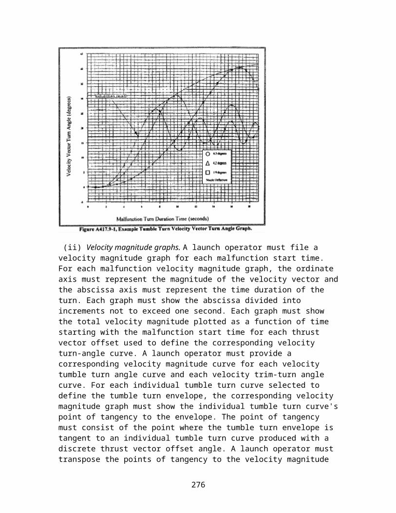
(3) Radio frequency dynamic range. The receiver decoder must satisfy all its performance specifications when subjected to the variations of the radio frequency input signal level that will occur during checkout and flight. The receiver decoder must output all commands with input from the radio frequency threshold level up to:
(i) The maximum radio frequency level that it will experience from the command control system transmitter during checkout and flight plus a 3-dB margin; or
(ii) 13 dBm, whichever is greater.
(4) Capture ratio. For each launch, the receiver decoder's design must ensure that no transmitter with less than 80% of the power of the command transmitter system for the launch, could capture or interfere with the receiver decoder.
(5) Radio frequency level monitor. (i) The receiver decoder must include a monitoring circuit that accurately monitors and outputs the strength of the radio frequency input signal during flight.
(ii) The output of the monitor circuit must be directly related and proportional to the strength of the radio frequency input signal from the threshold level to saturation.
(iii) The dynamic range of the radio frequency input from threshold to saturation must be no less than 50 dB. The monitor circuit output amplitude from threshold to saturation must have a corresponding range of 18 dB or greater.
(iv) The monitor output signal level must be compatible with vehicle telemetry system interfaces and provide a maximum response time of 100 ms.
(v) The slope of the monitor circuit output must not change polarity.
(6) Radio frequency threshold sensitivity. The receiver decoder's threshold sensitivity must satisfy its performance specifications and be repeatable within a tolerance of plus and minus 3 dB, to demonstrate in-family performance.
(7) Noise level margin. The receiver decoder's guaranteed input sensitivity must be no less than 6 dB higher than the maximum predicted noise-floor.
(8) Voltage standing wave ratio. All radio frequency losses within the receiver decoder interface to the antenna system must satisfy the 12–dB margin of §417.9(d) and be repeatable to demonstrate in-family performance. The radio frequency receiving system and the impedance of the receiver decoder must match.
(9) Decoder channel bandwidth. The receiver decoder must provide for reliable recognition of the command signal when subjected to variations in ground transmitter tone frequency and frequency modulation deviation variations. The command receiver must satisfy all its performance specifications within the specified tone filter frequency
276

bandwidth using a frequency modulation tone deviation from 2 dB to 20 dB above the measured threshold level.
(10) Tone balance. Any secure receiver decoder must reliably decode a valid command with an amplitude imbalance between two tones within the same message.
(11) Message timing. Any secure receiver decoder must function reliably when subjected to errors in timing caused by ground transmitter tolerances. The receiver decoder must process commands at twice the maximum and one-half the minimum timing specification of the ground system.
(12) Check tone. The receiver decoder must decode a tone, such as a pilot tone or check tone, which is representative of link and command closure and provide a telemetry output indicating whether the tone is decoded. The presence or absence of this tone signal must have no effect on a command receiver decoder's command processing and output capability.
(c) Inadvertent command output. A command receiver decoder must satisfy all of the following to ensure that it does not provide an output other than when it receives a valid command.
(1) Dynamic stability. The receiver decoder must not produce an inadvertent output when subjected to a radio frequency input short-circuit, open-circuit, or changes in input voltage standing wave ratio.
(2) Out of band rejection. The receiver decoder must not degrade in performance nor respond when subjected to any out-of-band vehicle or ground transmitter source that could be encountered from liftoff to the no-longer endanger time. The receiver decoder must not respond to frequencies, from 10 MHz to 1000 MHz except at the receiver specified operational bandwidth. The receiver decoder's radio frequency rejection of out of band signals must provide a minimum of 60 dB beyond eight times the maximum specified operational bandwidth. These frequencies must include all expected interfering transmitting sources using a minimum bandwidth of 20% of each transmitter center frequency, receiver image frequencies and harmonics of the assigned center frequency.
(3) Decoder channel bandwidth rejection. The receiver decoder must distinguish between tones that are capable of inhibiting or inadvertently issuing an output command. Each tone filter must not respond to another tone outside the specified tone filter frequency bandwidth using an FM tone deviation from 2 dB to 20 dB above the measured threshold level.
(4) Adjacent tone decoder channel rejection. The receiver decoder must not be inhibited or inadvertently issue an output command when subjected to any over-modulation of adjacent tones. The tone decoder channels must not respond to adjacent frequency modulation-modulated tone channels when they are modulated with a minimum of 150% of the expected tone deviation.
277

(5) Logic sequence. Each tone sequence used for arm and destruct must protect against inadvertent or unintentional destruct actions.
(6) Destruct sequence. The receiver decoder must provide a Destruct command only if preceded by a valid Arm command.
(7) Receiver abnormal logic. The receiver decoder must not respond to any combination of tones or tone pairs other than the correct command sequence.
(8) Noise immunity. The receiver decoder must not respond to a frequency modulated white noise radio frequency input that has a minimum frequency modulated deviation of 12 dB above the measured threshold deviation.
(9) Tone drop. The receiver decoder must not respond to a valid command output when one tone in the sequence is dropped.
(10) Amplitude modulation rejection. The receiver decoder must not respond to any tone or modulated input at 50% and 100% amplitude modulated noise when subjected to the maximum pre-flight and flight input power levels.
(11) Decoder channel deviation rejection. The receiver decoder must not inadvertently trigger on frequency modulated noise. The receiver decoder must not respond to tone modulations 10 dB below the nominal tone modulation or lower.
D417.31 Wiring and connectors
(a) All wiring, including any cable and all connectors, that interface with any flight termination system component must provide for the component, wiring, and connectors to satisfy the qualification tests required by appendix E of this part.
(b) Each connector that interfaces with a flight termination system component must protect against electrical dropout and ensure electrical continuity as needed to ensure the component satisfies all its performance specifications.
(c) All wiring and connectors must have shielding that ensures the flight termination system satisfies all its performance specifications and will not experience an inadvertent destruct output when subjected to electromagnetic interference levels 20 dB greater than the greatest electromagnetic interference induced by launch vehicle and launch site systems.
(d) The dielectric withstanding voltage between mutually insulated portions of any component part must provide for the component to function at the component's rated voltage and satisfy all its performance specifications when subjected to any momentary over-potentials that could normally occur, such as due to switching or surge.
278
(e) The insulation resistance between mutually insulated portions of any component must provide for the component to function at its rated voltage. Any insulation material must satisfy all its performance specifications when subjected to workmanship, heat, dirt, oxidation, or loss of volatile material.
(f) The insulation resistance between wire shields and conductors, and between each connector pin must withstand a minimum workmanship voltage of at least 1,500 volts, direct current, or 150 percent of the rated output voltage, whichever is greater.
(g) If any wiring or connector will experience loads with continuous duty cycles of 100 seconds or greater, that wiring or connector, including each connector pin, must have a capacity of 150% of the design load. If any wiring or connector will experience loads that last less than 100 seconds, all wiring and insulation must provide a design margin greater than the wire insulation temperature specification.
(h) All wiring, including any cable or connector, must satisfy all its performance specifications when subjected to the pull force required by section E417.9(j) and any additional handling environment that the component could experience undetected.
(i) Redundant circuits that can affect a flight termination system's reliability during flight must not share any wiring harness or connector with each other.
(j) For any connector or pin connection that is not functionally tested once connected as part of a flight termination system or component, the design of the connector or pin connection must eliminate the possibility of a bent pin, mismating, or misalignment.
(k) The design of a flight termination system component must prevent undetectable damage or overstress from occurring as the result of a bent connector pin. An inadvertent initiation must not occur if a bent connector pin:
(1) Makes unintended contact with another pin;
(2) Makes unintended contact with the case of the connector or component; or
(3) Produces an open circuit.
(l) Each connector that can affect a flight termination system component's reliability during flight must satisfy the requirements of §417.309(b)(2) of this part.
(m) All connectors must positively lock to prevent inadvertent disconnection during launch vehicle processing and flight.
(n) The installation of all wiring, including any cable, must protect against abrasion and crimping of the wiring.
D417.33 Batteries
279
(a) Capacity. A flight termination system battery must have a manufacturer-specified capacity of no less than the sum total amp-hour and pulse capacity needed for:
(1) Any self discharge;
(2) All load and activation checks;
(3) All launch countdown checks;
(4) Any potential hold time;
(5) Any potential number of preflight re-tests due to potential schedule delays including the number of potential launch attempts that the battery could experience before it would have to be replaced;
(6) Two arm and two destruct command loads at the end of the flight; and
(7) A flight capacity of no less than 150% of the capacity needed to support a normal flight from liftoff to the planned safe flight state. For a launch vehicle that uses solid propellant, the flight capacity must be no less than a 30-minute hang-fire hold time.
(b) Electrical characteristics. A flight termination system battery, under all load conditions, including line loss, must have all the following electrical characteristics:
(1) The manufacturer specified minimum voltage must be no less than the minimum acceptance test voltage that satisfies the electrical component acceptance tests of appendix E of this part. For a battery used in a pulse application to fire an electro-explosive device, the manufacturer specified minimum voltage must be no less than the minimum qualification test voltage that satisfies the electro-explosive device qualification tests of appendix E of this part;
(2) A battery that provides power to an electro-explosive device initiator, including to any initiator fired simultaneously with another initiator, must:
(i) Deliver 150% of each electro-explosive device's all-fire current at the qualification test level. The battery must deliver the current to each ordnance initiator at the lowest system battery voltage;
(ii) Have a current pulse that lasts ten times longer than the duration required to initiate the electro-explosive device or a minimum workmanship screening level of 200 milliseconds, whichever is greater; and
(iii) Have a pulse capacity of no less than twice the expected number of arm and destruct command sets planned to occur during launch vehicle processing, preflight flight termination system end-to-end tests, plus flight commands including load checks, conditioning, and firing of initiators;
280

(3) The design of a battery and any activation procedures must ensure uniform cell voltage after activation. Activation must include any battery conditioning needed to ensure uniform cell voltage, such as peroxide removal or nickel cadmium preparation; and
(4) The design of a battery or the system using the battery must protect against undetectable damage to the battery from any reverse polarity, shorting, overcharging, thermal runaway, or overpressure.
(c) Service and storage life. The service and storage life of a flight termination system battery must satisfy all of the following:
(1) A flight termination system battery must have a total activated service life that provides for the battery to meet the capacity and electrical characteristics required by paragraphs (a) and (b) of this section; and
(2) A flight termination system battery must have a specified storage life. The battery must satisfy the activated service life requirement of paragraph (c)(1) of this section after experiencing its storage life, whether stored in an activated or inactivated state.
(d) Monitoring capability. A battery or the system that uses the battery must provide for monitoring the status of the battery voltage and current. The monitoring must be sufficient to detect the smallest change in voltage or current that would indicate any health problem with each battery. Monitoring accuracy must be consistent with the minimum and maximum voltage and current limits used for launch countdown. The design of a battery that requires heating or cooling to sustain performance must provide for monitoring the battery's temperature with a resolution of 0.5 °C.
(e) Battery identification. Each battery must have an attached permanent label with the component name, type of construction (including chemistry), manufacturer identification, part number, lot and serial number, date of manufacture, and storage life.
(f) Battery temperature control. Any battery heater must ensure even temperature regulation of all battery cells.
(g) Silver zinc batteries. Any silver zinc battery that is part of a flight termination system must satisfy all of the following:
(1) A silver zinc battery must consist of cells assembled from electrode plates that are manufactured together and without interruption;
(2) The design of a silver zinc battery must allow activation of each individual cell within the battery;
281

(3) For any silver zinc battery that may vent electrolyte mist as part of normal operations, the battery must satisfy all its performance specifications for pin-to-case and pin-to-pin resistances after the battery experiences the maximum normal venting;
(4) The design of a silver zinc battery and its cells must allow for the qualification, acceptance, and storage life extension testing required by appendix E of this part. A launch operator must ensure sufficient batteries and cells are available from the same lot to accomplish the required testing;
(5) Each silver zinc battery must have attached, no less than one additional cell from the same production lot, with the same lot date code, as the cells in the battery for use in cell acceptance verification tests. The cell must remain attached to the battery from the time of assembly until performance of the acceptance tests to ensure that the additional cell is subjected to all the same environments as the complete battery;
(6) The design of a silver zinc battery must permit voltage monitoring of each cell during open circuit voltage and load tests of the battery; and
(7) All cell and battery parts and materials and manufacturing parts, materials, and processes must undergo configuration control that ensures that each cell and battery has repeatable in-family performance unless each cell and battery undergoes lot testing that demonstrates repeatable in-family performance. The launch operator must identify and implement any lot testing that replaces configuration control.
(h) Rechargeable cells and batteries.
(1) Any rechargeable battery or cell that is part of a flight termination system must satisfy all the requirements of this section for each charge-discharge cycle.
(2) With the exception of any silver zinc battery, a rechargeable battery must satisfy all its performance specifications for five times the number of operating charge and discharge cycles expected of the battery throughout its life, including all acceptance testing, preflight testing, and flight. A silver zinc rechargeable battery must satisfy all its performance specifications for each operating charge-discharge cycle expected of the battery throughout its life, including all acceptance testing, preflight testing, and flight.
(3) A rechargeable battery must consist of cells from the same production lot. For a battery that consists of commercially produced nickel cadmium cells, each cell must be from the same production lot of no less than three thousand cells that are manufactured without interruption.
(4) The design of a silver zinc or commercial nickel cadmium battery and each of its cells must allow for the qualification and acceptance tests required by appendix E of this part. A launch operator must ensure sufficient batteries and cells are available to accomplish the required testing. A launch operator must identify and implement design and test
282

requirements for any other type of rechargeable battery proposed for use as part of a flight safety system.
(i) Commercial nickel cadmium cells and batteries. Any nickel cadmium battery that uses one or more commercially produced nickel cadmium cells and is part of a flight termination system must satisfy each of the following to demonstrate that each cell or battery satisfies all its performance specifications:
(1) The battery or cell must have repeatable capacity and voltage performance. Capacity must be repeatable within one percent for each charge and discharge cycle.
(2) Any battery or cell venting device must ensure that the battery or cell does not experience a loss of structural integrity or create a hazardous condition when subjected to electrical discharge, charging and short-circuit conditions.
(3) The battery or cell must retain its charge and provide its required capacity, including the required capacity margin, from the final charge used prior to launch to the planned safe flight state during flight at the maximum pre-launch and flight temperature. The cell or battery must not self-discharge more than 10% of its fully charged capacity after 72 hours at ambient temperature.
(4) The design of the battery must prevent current leakage from pin-to-pin or pin-to-case from creating undesired events or battery self-discharge. Pin-to-pin and pin-to-case resistances must be repeatable so that measurements of pin-to-pin and pin-to-case resistances can establish in-family performance and determine whether all battery wiring and connectors are installed according to the manufacturer's design specifications.
(5) The battery or battery case must be sealed to the required leak rate and not loose structural integrity or create a hazardous condition when subjected to the predicted operating conditions plus all required margins including any battery short-circuit. The battery or battery case must maintain its structural integrity when subjected to no less than 1.5 times the greatest operating pressure differential that could occur under qualification testing, preflight, or flight conditions.
(6) Any battery voltage, current, or temperature monitoring circuit that is part of the battery must have resolution, accuracy, and data rates that all for detecting whether the performance specifications are satisfied and detecting any out-of-family conditions.
(7) Any battery heater circuit, including any thermostat must ensure that all cells are heated uniformly and must allow for repeatable battery performance that satisfies all the battery's performance specifications. Any heating must ensure that cells are not overstressed due to excessive temperature. The thermostat tolerances must ensure that the battery remains within its thermal design limits.
(8) The battery or cell must satisfy all its electrical performance specifications and be in-family while subjected to all pre-flight and flight environments, including hot and cold
283

temperature, and all required electrical loads at the beginning, middle, and end of its manufacturer specified capacity.
D417.35 Electro-mechanical safe-and-arm devices with an internal electro-explosive device
(a) This section applies to any electro-mechanical safe-and-arm device that has an internal electro-explosive device and is part of a flight termination system. A safe-and-arm device must provide for safing and arming of the flight termination system ordnance to satisfy section D417.13.
(b) A safe-and-arm device in the arm position must remain in the arm position and satisfy all its performance specifications when subjected to the design environmental levels determined under section D417.7.
(c) All wiring and connectors used in a safe-and-arm device must satisfy section D417.31.
(d) Each piece-part that is used in the firing circuit of a safe-and-arm device and that can affect the reliability of the device during flight must satisfy §417.309(b)(2) of this part.
(e) A safe-and-arm device's internal electro-explosive device must satisfy the requirements for an ordnance initiator of section D417.41.
(f) A safe-and-arm device must not require any adjustment throughout its service life.
(g) A safe-and-arm device's internal electrical firing circuitry, such as wiring, connectors, and switch deck contacts, must satisfy all its performance specifications when subjected to an electrical current pulse with an energy level of no less than 150% of the internal electro-explosive device's all-fire energy level for 10 times as long as the all-fire pulse lasts. A safe-and-arm device must deliver this firing pulse to the internal electro-explosive device without any dropout that could affect the electro-explosive device's performance when subjected to the design environmental levels.
(h) A safe-and-arm device must satisfy all its performance specifications after being exposed to the handling drop required by section E417.9(k) and any additional transportation, handling, or installation environment that the device could experience undetected.
(i) A safe-and-arm device must not initiate and must allow for safe disposal after experiencing the abnormal drop required by section E417.9(l).
(j) When a safe-and-arm device's electro-explosive device is initiated, the safe- and arm-device's body must not fragment, regardless of whether the explosive transfer system is connected or not.
284

(k) When dual electro-explosive devices are used within a single safe-and-arm device, the design must ensure that one electro-explosive device does not affect the performance of the other electro-explosive device.
(l) A safe-and-arm device must satisfy all its performance specifications when subjected to no less than five times the total number of safe and arm cycles required for the combination of all acceptance tests, preflight tests, and flight operations, including an allowance for potential re-tests due to schedule changes.
(m) The design of a safe-and-arm device must allow for separate component testing and recording of parameters that verify its functional performance , and the status of any command output during the tests required by section E417.25.
(n) A safe-and-arm device must be environmentally sealed to the equivalent of 10−4scc/sec of helium at one atmosphere differential or the device must provide other means of withstanding non-operating environments, such as salt-fog and humidity, experienced during storage, transportation and preflight testing.
(o) The safing of a safe-and-arm device must satisfy all of the following:
(1) While in the safe position, a safe-and-arm device must protect each internal electro-explosive device from any condition that could degrade the electro-explosive device's performance and prevent inadvertent initiation during transportation, storage, preflight testing, and any preflight fault conditions.
(2) While in the safe position, a safe-and-arm device's electrical input firing circuit must prevent degradation in performance or inadvertent initiation of the electro-explosive device when the safe-and-arm device is subjected to any external energy source, such as static discharge, radio frequency energy, or firing voltage.
(3) While in the safe position, a safe-and-arm device must prevent the initiation of its internal electro-explosive device and any other ordnance train component, with a reliability of 0.999 at a 95% confidence level.
(4) A safe-and-arm device must satisfy all its performance specifications when in the safe position and subjected to the continuous operational arming voltage required by section E417.25(d).
(5) A safe-and-arm device must not initiate its electro-explosive device or any other ordnance train component when locked in the safe position and subjected to the continuous operational arming voltage required by section E417.25(e)(3).
(6) A safe-and-arm device must have a visual display of its status on the device and remote display of the status when the device is in the safe position. When transitioning from the arm to safe position, the safe indication must not appear unless the position of
285

the safe-and-arm device has progressed more than 50% beyond the no-fire transition motion.
(7) A safe-and-arm device must have a remote means of moving its rotor or barrier to the safe position from any rotor or barrier position.
(8) A safe-and-arm device must have a manual means of moving its rotor or barrier to the safe position.
(9) A safe-and-arm device must have a safing interlock that prevents movement from the safe position to the arm position while operational arming current is being applied. The interlock must have a means of positively locking into place and must allow for verification of proper functioning. The interlock removal design or procedure must eliminate the possibility of accidental disconnection of the interlock.
(p) The arming of a safe-and-arm device must satisfy all of the following:
(1) When a safe-and-arm device is in the arm position, all ordnance interfaces, such as electro-explosive device, rotor charge, and explosive transfer system components must align with one another to ensure propagation of the explosive charge with a reliability of 0.999 at a 95% confidence level;
(2) When in the arm position, the greatest energy supplied to a safe-and-arm device's electro-explosive device from electronic circuit leakage and radio frequency energy must be no greater than 20 dB below the guaranteed no-fire level of the electro-explosive device;
(3) A safe-and-arm device must have a visual display of its status on the device and provide for remote display of the status when the device is in the arm position. The arm indication must not appear unless the safe-and-arm device is armed as required by paragraph (o)(1) of this section; and
(4) A safe-and-arm device must provide for remote arming of the device.
D417.37 Exploding bridgewire firing unit
(a) General. This section applies to any exploding bridgewire firing unit that is part of a flight termination system. An exploding bridgewire firing unit must provide for safing and arming of the flight termination system ordnance to satisfy section D417.13. An exploding bridgewire firing unit must satisfy the requirements for electronic components of section D417.29.
(b) Charging and discharging. An exploding bridgewire firing unit must have a remote means of charging and discharging of the unit's firing capacitor and an external means of positively interrupting the firing capacitor charging voltage.
286

(c) Input command processing. An exploding bridgewire firing unit's electrical input processing circuitry must satisfy all of the following:
(1) An exploding bridgewire firing unit's input circuitry must function, when subjected to the greatest potential electromagnetic interference noise environments, without inadvertently triggering;
(2) In the firing circuit of an exploding bridgewire firing unit, all series redundant branches that prevent any single failure point from issuing a destruct output must include monitoring circuits or test points for verifying the integrity of each redundant branch after assembly;
(3) The unit input trigger circuitry of an exploding bridgewire firing unit must maintain a minimum 20 dB margin between the threshold trigger level and the worst-case noise environment;
(4) An exploding bridgewire firing unit must have a minimum trigger sensitivity that provides for the unit to fire at 6 dB lower in amplitude and one-half the duration of the worst-case trigger signal that the unit could receive during flight;
(5) In the event of a power dropout, any control or switching circuit critical to the reliable operation of an exploding bridgewire firing unit, including solid-state power transfer switches, must not change state for 50 milliseconds or more; and
(6) An exploding bridgewire firing unit's response time must satisfy all its performance specifications for the range of input trigger signals from the specified minimum trigger signal amplitude and duration to the specified maximum trigger signal amplitude and duration.
(d) High voltage output. An exploding bridgewire firing unit's high voltage discharge circuit must satisfy all of the following:
(1) An exploding bridgewire firing unit must include circuits for capacitor charging, bleeding, charge interruption, and triggering;
(2) An exploding bridgewire firing unit must have a single fault tolerant capacitor discharge capability;
(3) An exploding bridgewire firing unit must deliver a voltage to the exploding bridgewire that is no less than 50% greater than the exploding bridgewire's minimum all-fire voltage, not including transmission losses, at the unit's worst-case high and low arming voltages;
(4) The design of an exploding bridgewire firing unit must prevent corona and arcing on internal and external high voltage circuitry;
287

(5) An exploding bridgewire firing unit must satisfy all its performance specifications at the worst-case high and low arm voltages that could be delivered during flight; and
(6) Any high energy trigger circuit used to initiate exploding bridgewire firing unit's main firing capacitor must deliver an output signal of no less than a 50% voltage margin above the nominal voltage threshold level.
(e) Output monitors. The monitoring circuits of an exploding bridgewire firing unit must provide the data for real-time checkout and determination of the firing unit's acceptability for flight. The monitored data must include the voltage level of all high voltage capacitors and the arming power to the firing unit.
D417.39 Ordnance interrupter safe-and-arm device without an electro-explosive device
(a) This section applies to any ordnance interrupter safe-and-arm device that does not have an internal electro-explosive device and is part of a flight termination system. An ordnance interrupter must provide for safing and arming of the flight termination system ordnance to satisfy section D417.13.
(b) An ordnance interrupter must remain in the armed position and satisfy all its performance specifications when subjected to the design environmental levels determined according to section D417.7.
(c) An ordnance interrupter must not require adjustment throughout its service life.
(d) An ordnance interrupter must satisfy all its performance specifications after experiencing any transportation, handling, or installation environment that the device could experience undetected.
(e) An ordnance interrupter that uses ordnance rotor leads must not initiate and must allow for safe disposal after experiencing the worst-case drop and resulting impact that it could experience during storage, transportation, or installation.
(f) An ordnance interrupter must satisfy all of its performance specifications when subjected to repetitive functioning for five times the expected number of arming cycles required for acceptance testing, preflight checkout, and flight operations, including an allowance for re-tests due to potential schedule delays.
(g) An ordnance interrupter must not fragment during ordnance initiation.
(h) The design of a flight termination system must protect an ordnance interrupter from conditions that could degrade its performance or cause inadvertent initiation during transportation, storage, installation, preflight testing, and potential preflight fault conditions. Safing of an ordnance interrupter must satisfy all of the following:
288
(1) While in the safe position, an ordnance interrupter must prevent the functioning of an ordnance train with a reliability of 0.999 at a 95% confidence level;
(2) When locked in the safe position, an ordnance interrupter must prevent initiation of an ordnance train. The ordnance interrupter must satisfy all its performance specification when locked in the safe position and subjected to the continuous operational arming voltage required by section E417.29(j);
(3) An ordnance interrupter must not initiate its electro-explosive device or any other ordnance train component when locked in the safe position and subjected to the continuous operational arming voltage required by section E417.29(e)(3);
(4) An ordnance interrupter must have a manual and a remote means of safing from any rotor or barrier position;
(5) An ordnance interrupter must have a visual display of the status on the device and provide for remote display of the status when the ordnance interrupter is in the safe position; and
(6) An ordnance interrupter must include a safing interlock that prevents the interrupter from moving from the safe position to the arm position when subjected to an operational arming current. A safing interlock must have a means of positively locking into place and a means of verifying proper function of the interlock. A safing interlock and any related operation procedure must eliminate the possibility of inadvertent disconnection of the interlock.
(i) Arming of an ordnance interrupter must satisfy all of the following:
(1) An ordnance interrupter is armed when all ordnance interfaces, such as a donor explosive transfer system, rotor charge, and acceptor explosive transfer system are aligned with one another to propagate the explosive charge with a reliability of 0.999 at a 95% confidence level;
(2) An ordnance interrupter must have a visual display of the status on the device and provide for remote display of the status when the ordnance interrupter is in the arm position; and
(3) An ordnance interrupter must provide for remote arming of the interrupter.
D417.41 Ordnance initiators
(a) This section applies to any low-voltage electro-explosive device that is part of a flight termination system or high-voltage exploding bridgewire ordnance initiator that is part of a flight termination system. An ordnance initiator must use electrical energy to trigger an explosive charge that initiates the flight termination system ordnance.
289
(b) An ordnance initiator must have a manufacturer-specified all-fire energy level. When the all-fire energy level is applied, the ordnance initiator must fire with a reliability of no less than 0.999 at a 95 percent confidence level.
(c) An ordnance initiator must have a specified no-fire energy level. An ordnance initiator must not fire when exposed to continuous application of the no-fire energy level, with a reliability of no less than 0.999 at a 95 percent confidence level. An ordnance initiator must satisfy all its performance specifications when subjected to continuous application of the no-fire energy level.
(d) The lowest temperature at which an ordnance initiator would experience autoignition, sublimation, or melting or in any other way experience degradation in performance must be no less than 30 °C higher than the highest temperature that the initiator could experience prior to or during flight.
(e) An ordnance initiator must not fire, and must satisfy all its performance specifications when subjected to the maximum expected electrostatic discharge that it could experience from personnel or conductive surfaces. An ordnance initiator must not fire, and must satisfy all its performance specifications when subjected to workmanship discharges of no less than a 25-kV, 500-pF pin-to-pin discharge through a 5-kΩ resistor and a 25-kV, 500-pF pin-to-case discharge with no resistor.
(f) An ordnance initiator must not initiate and must satisfy all its performance specifications when exposed to stray electrical current that is at a 20-dB margin greater than the greatest stray electrical current that the ordnance initiator could experience prior to or during flight. When determining the 20-dB margin, a launch operator must account for all potential sources of stray electrical current, including leakage current from other electronic components and radio frequency induced electrical current.
(g) An ordnance initiator must satisfy all its performance specification after being exposed to the tensile load required by section E417.9(j), the handling drop required by section E417.9(k), and any additional transportation, handling, or installation environment that the device could experience undetected.
(h) An ordnance initiator must not initiate and must allow for safe disposal after experiencing the abnormal drop required by section E417.9(l).
(i) An ordnance initiator must be hermetically sealed to the equivalent of 5 × 10⁻⁶scc/sec of helium at one atmosphere pressure differential.
(j) The insulation resistance between mutually insulated points must ensure that an ordnance initiator satisfies all its performance specifications when subjected to the greater of twice the maximum applied voltage during testing and flight or a workmanship voltage of no less than 500 volts. The insulation material must satisfy all its performance specifications when exposed to workmanship, heat, dirt, oxidation, and any additional expected environment.
290

D417.43 Exploding bridgewire
(a) This section applies to any exploding bridgewire that is part of a flight termination system. An exploding bridgewire must use high-voltage electrical energy of 50 volts or greater to trigger an explosive charge that initiates the flight termination system ordnance.
(b) An exploding bridgewire must satisfy the ordnance initiator requirements of section D417.41.
(c) An exploding bridgewire's electrical circuitry, such as connectors, pins, wiring and header assembly, must transmit an all-fire pulse at a level 50% greater than the lowest exploding bridgewire firing unit's operational firing voltage. This must include allowances for effects such as corona and arcing of a flight configured exploding bridgewire exposed to altitude, thermal vacuum, salt-fog, and humidity environments.
(d) An exploding bridgewire must not fragment during ordnance initiation.
(e) All exploding bridgewire connector pins must withstand the tension and compression loads required by section E417.9(j).
D417.45 Percussion-activated device
(a) This section applies to any percussion-activated device that is part of a flight termination system. A percussion-activated device must use mechanical energy to trigger an explosive charge that initiates the flight termination system ordnance.
(b) A percussion-activated device's lanyard pull system must have a protective cover or other feature that prevents inadvertent pulling of the lanyard.
(c) A percussion-activated device must not fragment upon initiation.
(d) A percussion-activated device must have a guaranteed no-fire pull force of no less than twice the largest inadvertent pull force that the device could experience:
(1) Any time prior to flight that the safing interlock of paragraph (o) of this section is not in place; or
(2) During flight.
(e) A percussion-activated device must not initiate when pulled with its maximum no-fire pull force and then released with a reliability of no less than 0.999 at a 95% confidence level.
291

(f) A percussion-activated device must have a primer all-fire energy level, including spring constant and pull distance that ensures initiation, with a reliability of no less than 0.999 at a 95% confidence level when subjected to preflight and flight environments.
(g) A percussion-activated device must deliver an operational impact force to the primer of no less than twice the all-fire energy level.
(h) A percussion-activated device's primer must initiate and must satisfy all its performance specifications when subjected to two times the operational impact energy or four times the all-fire impact energy level.
(i) A percussion-activated device's reliability must satisfy its performance specifications when subjected to a no-fire pull force and then released.
(j) The lowest temperature at which a percussion-activated device would experience autoignition, sublimation, or melting, or in any other way not satisfy its performance specifications, must be no less than 30 °C higher than the highest temperature that the percussion-activated device could experience prior to or during flight.
(k) A percussion-activated device must satisfy all its performance specifications after experiencing the handling drop required by section E417.9(k) and any additional transportation, handling, or installation environment that the device could experience undetected.
(l) A percussion-activated device's ordnance must be hermetically sealed to the equivalent of 5 × 10⁻⁶scc/sec of helium at one atmosphere differential.
(m) A percussion-activated device's structural and firing components must withstand 500 percent of the largest pull or jerk force that the device could experience during breakup of the launch vehicle.
(n) A percussion-activated device must not initiate and must allow for safe disposal after experiencing the abnormal drop required by section E417.9(l).
(o) A percussion-activated device must include a safing interlock, such as a safing pin, that provides a physical means of preventing the percussion-activated device assembly from pulling more than 50% of the guaranteed no-fire pull distance. The following apply to a safing interlock:
(1) A safing interlock must positively lock into place and must have a means of verifying proper function of the interlock.
(2) A safing interlock must eliminate the possibility of inadvertent disconnection or removal of the interlock should a pre-load condition exist on the lanyard unless the device provides a visual or other means of verifying that there is no load on the lanyard.
292

(3) A safing interlock, when in place, must prevent initiation of the percussion actuated device when subjected to twice the greatest possible inadvertent pull force that could be experienced during launch processing.
D417.47 Explosive transfer system
(a) This section applies to any explosive transfer system that is part of a flight termination system. An explosive transfer system must transmit an explosive charge from an initiation source, such as an ordnance initiator, to other flight termination system ordnance such as a destruct charge.
(b) Ordnance used in an explosive transfer system must consist of a secondary explosive. An exception to this is any transition component that contains a primary explosive that is fully contained within the transition component. Any transition component that contains a primary explosive must be no more sensitive to inadvertent detonation than a secondary explosive.
(c) An explosive transfer system, including all donor, acceptor, and transition charges and components must transfer an explosive charge with a reliability of no less than 0.999 at a 95% confidence level.
(d) An explosive transfer system must satisfy all its performance specifications with the smallest bend radius that it is subjected to when installed in its flight configuration.
(e) All explosive transfer connectors must positively lock in place and provide for verification of proper connection through visual inspection.
(f) Each explosive transfer system component must satisfy all its performance specifications when subjected to the tensile load required by section E417.9(j).
(g) An explosive transfer system must satisfy all its performance specifications after experiencing the handling drop required by section E417.9(k) and any additional transportation, handling, or installation environment that the system could experience undetected.
(h) An explosive transfer system must not initiate and must allow for safe disposal after experiencing the abnormal drop required by section E417.9(l).
(i) An explosive transfer system must be hermetically sealed to the equivalent of 5 × 10⁻⁶scc/sec of helium at one atmosphere pressure differential.
D417.49 Destruct charge
(a) This section applies to any destruct charge that is part of a flight termination system. A destruct charge must sever or penetrate a launch vehicle component or payload, such as a propellant tank or motor casing, to accomplish a flight termination function.
293

(b) A destruct charge must use a secondary explosive.
(c) When initiated, a destruct charge acceptor, where applicable, or main charge must ensure the transfer of the explosive charge with a reliability of 0.999 at a 95% confidence level.
(d) Initiation of a destruct charge must result in a flight termination system action in accordance with the flight termination system functional requirements of §417.303.
(e) A destruct charge must sever or penetrate 150% of the thickness of the material that must be severed or penetrated in order for the destruct charge to accomplish its intended flight termination function. A destruct charge, when initiated to terminate the flight of a launch vehicle, must not detonate any launch vehicle or payload propellant.
(f) Each destruct charge and associated fitting must satisfy all its performance specifications when subjected to the tensile load required by section E417.9(j).
(g) A destruct charge must satisfy all its performance specifications after experiencing the handling drop required by section E417.9(k) and any additional transportation, handling, or installation environment that the charge could experience undetected.
(h) A destruct charge must not initiate and must allow for safe disposal after experiencing the abnormal drop required by section E417.9(l).
(i) A destruct charge must be hermetically sealed to the equivalent of 5 × 10⁻⁶scc/sec of helium at one atmosphere pressure differential.
D417.51 Vibration and shock isolators
(a) This section applies to any vibration or shock isolator that is part of a flight safety system. A vibration or shock isolator must ensure the environmental survivability of a flight termination system component by reducing the vibration or shock levels that the component experiences during flight.
(b) A vibration or shock isolator must have repeatable natural frequency and resonant amplification parameters when subjected to flight environments.
(c) An isolator must account for all effects that could cause variations in repeatability, including acceleration preloads, temperature, component mass, and vibration level variations.
(d) A vibration or shock isolator must satisfy all of its performance specifications when subjected to the qualification test environments for each component that is mounted on the isolator.
294

(e) All components mounted on a vibration or shock isolator must withstand the environments introduced by isolator amplification. In addition, all component interface hardware, such as connectors, cables, and grounding straps, must withstand any added deflection introduced by an isolator.
D417.53 Miscellaneous components
(a) This section applies to any miscellaneous flight termination system component that is not specifically identified by this appendix.
(b) A miscellaneous component must satisfy all its performance specifications when subjected to the non-operating and operating environments of section D417.3.
(c) The design of a miscellaneous component must provide for the component to be tested in accordance with appendix E of this part.
(d) A launch operator must identify any additional requirements that apply to any new or unique component and demonstrate that those requirements ensure the reliability of the component.
295

Appendix E to Part 417—Flight Termination System Testing and Analysis
E417.1 General
(a) Scope and compliance. This appendix contains requirements for tests and analyses that apply to all flight termination systems and the components that make up each flight termination system. Section 417.301 requires that a launch operator's flight safety system employ a flight termination system that complies with this appendix. Section 417.301 also contains requirements that apply to a launch operator's demonstration of compliance with the requirement of this appendix. A launch operator must employ on its launch vehicle only those flight termination system components that satisfy the requirements of this appendix.
(b) Component tests and analyses. A component must satisfy each test or analysis required by any table of this appendix to demonstrate that the component satisfies all its performance specifications when subjected to non-operating and operating environments. A launch operator must identify and implement any additional test or analysis for any new technology or any unique application of an existing technology.
(c) Test plans. Each test of a component, subsystem, or system must follow a written plan that specifies the test parameters, including pass/fail criteria, and a testing sequence that satisfy the requirements of this appendix. For any component that is used for more than one flight, the test plan must provide for component reuse qualification, refurbishment, and acceptance as required by section E417.7(g). The test plan must include any alternate procedures for testing a component when it is in place on the launch vehicle.
(d) Test failures. If a test of a component results in a failure, the component does not satisfy the test requirement. Each of the following is a test failure:
(1) Any component sample that does not satisfy a performance specification;
(2) Any failure to accomplish a test objective;
(3) Any component sample with a test result that indicates that the component is out-of-family when compared to other samples of the component, even if the component satisfies other test criteria;
(4) Any unexpected change in the performance of a component sample occurring at any time during testing;
(5) Any component sample that exhibits any sign that a part is stressed beyond its design limit, such as a cracked circuit board, bent clamps, worn part, or loose connector or screw, even if the component passes the final functional test;
296

(6) When component examination shows any defect that could adversely affect the component's performance;
(7) Any discontinuity or dropout in a measured performance parameter that could prevent the component from satisfying a performance specification;
(8) Any inadvertent output; or
(9) Any indication of internal component damage.
(e) Failure analysis. In the event of a test failure, the test item, procedures and equipment must undergo a written failure analysis. The failure analysis must identify the cause of the failure, the mechanism of the failure, and isolate the failure to the smallest replaceable item or items and ensure that there are no generic design, workmanship, or process problems with other flight components of similar configuration.
(f) Test tolerances. Each test must apply to the nominal values specified by this appendix tolerances that satisfy the following:
(1) The tolerance of any measurement taken during a functional test must provide the accuracy needed to detect any out-of-family or out-of-specification anomaly.
(2) An environmental level, such as for vibration or temperature, used to satisfy a component test requirement of this appendix must include the environment design margin required by appendix D of this part. The environmental level must account for any test equipment tolerance to ensure that the component experiences the required margin.
(g) Test equipment. All equipment used during environmental testing must provide for the test item to experience the required environmental test levels. Any test fixture used to simultaneously test multiple component samples must ensure that each component sample, at each mounting location on the fixture experiences each required environmental test level. Any difference in a qualification or acceptance test fixture or cable must undergo an evaluation to ensure that flight hardware is not subjected to stresses greater than that which the unit experiences during qualification.
(h) Rework and repair of components. Components that fail a test may undergo rework and repair and must then complete the failed test and each remaining test. If a repair requires disassembly of the component or soldering operations, the component must repeat any test necessary to demonstrate that the repair corrected the original anomaly and did not cause other damage. The total number of acceptance tests experienced by a repaired component must not exceed the environments for which the component is qualified.
(i) Test and analysis reports. A launch operator must prepare or obtain one or more written reports that:
297

(1) Describe all flight termination system test results and test conditions;
(2) Describe any analysis performed instead of testing;
(3) Identify, by serial number or other identification, each test result that applies to each system or component;
(4) Describe any family performance data to be used for comparison to any subsequent test of a component or system;
(5) Describe all performance parameter measurements made during component testing for comparison to each previous and subsequent test to identify any performance variations that may indicate a potential workmanship or other defect that could lead to a failure of the component during flight; and
(6) Identify any test failure or anomaly, including any variation from an established performance baseline, with a description of the failure or anomaly, each corrective action taken, and all results of additional tests.
E417.3 Component test and analysis tables
(a) General. This section applies to each test and analysis table of this appendix. Each component or system that is identified by a table must satisfy each test or analysis identified by the table. Each component or system must satisfy a test by undergoing and passing the test as described in the paragraph that the table lists. In cases where the listed paragraph allows a test or analysis, any analysis must satisfy any specific requirement listed in the paragraph and must demonstrate one of the following:
(1) The test environment does not apply to the component;
(2) The test environment does not degrade the component's performance; or
(3) Another test or combination of tests that the component undergoes places equal or greater stress on the component than the test in question.
(b) Test sequence. A component or system must undergo each test in the same order as the table identifies the test. A launch operator may deviate from the test sequence if the launch operator demonstrates that another order will detect any component anomaly that could occur during testing.
(c) Quantity of sample components tested.
(1) For a new component, each table identifies the quantity of component samples that must undergo each test identified by the table.
298
(2) A launch operator may test fewer samples than the quantity identified for a new component if the launch operator demonstrates one of the following:
(i) That the component has experienced comparable environmental tests; or
(ii) The component is similar to a design that has experienced comparable environmental tests.
(3) Any component that a launch operator uses for any comparison to a new component must have undergone all the environmental tests required for the new component to develop cumulative effects.
(d) Performance verification tests. Each performance verification test identified by any table of this appendix must satisfy all of the following:
(1) Each test must measure one or more of a component or system's performance parameters to demonstrate that the component or system satisfies all its performance specifications;
(2) The component must undergo each test:
(i) Before the component is exposed to each test environment; and
(ii) After the component is exposed to the test environment to identify any performance degradation due to the environment; and
(3) Any electronic component must undergo each performance verification test at:
(i) The lowest operating voltage;
(ii) Nominal operating voltage; and
(iii) Highest operating voltage that the component could experience during pre-flight and flight operations.
(e) Abbreviated performance verification tests. Each abbreviated performance verification test required by any table of this appendix must satisfy all of the following:
(1) Each test must exercise all of a component's functions that are critical to a flight termination system's performance during flight
(i) while the component is subjected to each test environment; or,
(ii) for short duration environments such as shock, before and after each test;
299
(2) Each test must measure a sampling of the component's critical performance parameters while the component is subjected to each test environment to demonstrate that the component satisfies all its performance specifications; and
(3) Any electronic component must undergo each abbreviated performance verification test at the component's nominal operating voltage.
(f) Status-of-health tests. Each status-of-health test required by any table of this appendix must satisfy all of the following:
(1) Each test must measure one or more critical performance parameter to demonstrate that a component or system satisfies all its performance specifications;
(2) The critical performance parameters must include those parameters that act as an indicator of an internal anomaly that a functional performance test might not detect; and
(3) Each test must compare the results to any previous test results to identify any degradation in performance.
E417.5 Component examination
(a) General. This section applies to each component examination identified by any table of this appendix. Each component examination must identify any manufacturing defect that the performance tests might not detect. The presence of a defect that could adversely affect the component's performance constitutes a failure.
(b) Visual examination. A visual examination must verify that good workmanship was employed during manufacture of a component and that the component is free of any physical defect that could adversely affect performance. A visual examination may include the use of optical magnification, mirrors, or specific lighting, such as ultraviolet illumination.
(c) Dimension measurement. A dimension measurement of a component must verify that the component satisfies all its dimensional specifications.
(d) Weight measurement. A weight measurement of a component must verify that the component satisfies its weight specification.
(e) Identification check. An identification check of a component must verify that the component has one or more identification tags that contain information that allows for configuration control and tracing of the component.
(f) X-ray and N-ray examination. An X-ray or N-ray examination of a component must have a resolution that allows detailed inspection of the internal parts of the component and must identify any internal anomalous condition. The examination must include enough photographs, taken from different angles, to allow complete coverage of the
300

component's internal parts. When utilized as a recurring inspection technique to accept production hardware, the examination must use the same set of angles for each sample of a component to allow for comparison. A certified technician must evaluate X-ray and N-ray photographs.
(g) Internal inspection. An internal inspection of a component must demonstrate that there is no wear or damage, including any internal wear or damage, to the component that could adversely affect its performance after exposure to any test environment. An internal inspection must satisfy all of the following:
(1) All internal components and subassemblies, such as circuit board traces, internal connectors, welds, screws, clamps, electronic piece parts, battery cell plates and separators, and mechanical subassemblies must undergo examination to satisfy this paragraph using an inspection method such as a magnifying lens or radiographic inspection;
(2) For a component that can be disassembled, the component must undergo complete disassembly to the point needed to satisfy this paragraph; and
(3) For a component that cannot be disassembled, such as an antenna, potted component, or welded structure, the component must undergo any special procedures needed to satisfy this paragraph, such as depotting the component, cutting the component into cross-sections, or radiographic inspection.
(h) Leakage. A leakage test must demonstrate that a component's seal satisfies all its performance specifications before and after the component is subjected to any test environment as follows:
(1) The test must have the resolution and sample rate to demonstrate that the component's leak rate is no greater than its design limit.
(2) For an electronic component, the test must demonstrate a leak rate of no greater than the equivalent of 10−4 standard cubic centimeters/second (scc/sec) of helium.
(3) For an ordnance component, the test must demonstrate a leak rate of no greater than the equivalent of 5 × 10⁻⁶ scc/sec of helium.
E417.7 Qualification testing and analysis
(a) This section applies to each qualification non-operating and operating test or analysis identified by any table of this appendix. A qualification test or analysis must demonstrate that a component will satisfy all its performance specifications when subjected to the design environmental levels required by section D417.7.
(b) Before a component sample undergoes a qualification environmental test, the component sample must pass all the required acceptance tests.
301
(c) A component must undergo each qualification test in a flight representative configuration, with all flight representative hardware such as connectors, cables, and any cable clamps, and with all attachment hardware, such as dynamic isolators, brackets and bolts, as part of that flight representative configuration.
(d) A component must undergo re-qualification tests if there is a change in the design of the component or if the environmental levels to which it will be exposed exceed the levels for which the component is qualified. A component must undergo re-qualification if the manufacturer's location, parts, materials, or processes have changed since the previous qualification. A change in the name of the manufacturer as a result of a sale does not require re-qualification if the personnel, factory location or the parts, material and processes remain unchanged since the last component qualification. The extent of any re-qualification tests must be the same as the initial qualification tests except where paragraph (f) of this section applies.
(e) A launch operator must not use for flight any component sample that has been subjected to a qualification test environment.
(f) A launch operator may reduce the testing required to qualify or re-qualify a component's design through qualification by similarity to tests performed on identical or similar hardware. To qualify component “A” based on similarity to component “B” that has already been qualified for use, a launch operator must demonstrate that all of the following conditions are satisfied:
(1) “B” must have been qualified through testing, not by similarity;
(2) The environments encountered by “B” during its qualification or flight history must have been equal to or more severe than the qualification environments required for “A;”
(3) “A” must be a minor variation of “B.” The demonstration that A is a minor variation of B must account for all of the following:
(i) Any difference in weight, mechanical configuration, thermal effects, or dynamic response;
(ii) Any change in piece-part quality level; and
(iii) Any addition or subtraction of an electronic piece-part, moving part, ceramic or glass part, crystal, magnetic device, or power conversion or distribution equipment;
(4) “A” and “B” must perform the same functions, with “A” having equivalent or better capability; and
(5) The same manufacturer must produce “A” and “B” in the same location using identical tools and manufacturing processes;
302
(g) For any flight termination system component used for more than one flight, the component qualification tests must demonstrate that the component satisfies all its performance specifications when subjected to:
(1) Each qualification test environment; and
(2) The total number of exposures to each maximum predicted environment for the total number of flights.
E417.9 Qualification non-operating environments
(a) General . This section applies to each qualification non-operating environment test or analysis identified by any table of this appendix. A qualification non-operating test or analysis must demonstrate that a component satisfies all its performance specifications when subjected to each maximum predicted non-operating environment that the component could experience, including all storage, transportation, and installation environments.
(b) Storage temperature. A storage temperature test or analysis must demonstrate that a component will satisfy all its performance specifications when subjected to the maximum predicted high and low temperatures, thermal cycles, and dwell-times at the high and low temperatures that the component could experience under storage conditions as follows:
(1) Any storage temperature test must subject the component to the range of temperatures from 10 °C lower than the maximum predicted storage thermal range to 10 °C higher. The rate of change from one thermal extreme to the other must be no less than the maximum predicted thermal rate of change. All thermal dwell-times and thermal cycles must be no less than those of the maximum predicted storage environment.
(2) Any analysis must demonstrate that the qualification operating thermal cycle environment is more severe than the storage thermal environment by satisfying one of the following:
(i) The analysis must include thermal fatigue equivalence calculations that demonstrate that the large change in temperature for a few thermal cycles experienced during flight is a more severe environment than the relatively small change in temperature for many thermal cycles that would be experienced during storage; or
(ii) The analysis must demonstrate that the component's operating qualification thermal cycle range encompasses –34 °C to 71 °C and that any temperature variation that the component experiences during storage does not exceed 22 °C.
(c) High-temperature storage of ordnance. A component may undergo a high-temperature storage test to extend the service-life of an ordnance component production lot from one year to three or five years as permitted by any test table of this appendix. The test must demonstrate that each component sample satisfies all its performance
303

specifications after being subjected to +71 °C and 40 to 60 percent relative humidity for no less than 30 days each.
(d) Transportation shock. A transportation shock test or analysis must demonstrate that a component satisfies all its performance specifications after being subjected to the maximum predicted transportation induced shock levels that the component could experience when transported in its transported configuration. Any analysis must demonstrate that the qualification operating shock environment is more severe than the transportation shock environment.
(e) Bench handling shock. A bench handling shock test must demonstrate that a component satisfies all its performance specifications after being subjected to maximum predicted bench handling induced shock levels. The test must include, for each orientation that could occur during servicing; a drop from the maximum predicted handling height onto a representative surface.
(f) Transportation vibration. A transportation vibration test or analysis must demonstrate that a component satisfies all its performance specifications after being subjected to a maximum predicted transportation-induced vibration level when transported in its transportation configuration as follows:
(1) Any transportation vibration test must subject a component to vibration in three mutually perpendicular axes for 60 minutes per axis. The test must subject each axis to the following vibration profile:
(i) 0.01500 g2 /Hz at 10 Hz to 40 Hz;
(ii) 0.01500 g2 /Hz at 40 Hz to 0.00015 g2 /Hz at 500 Hz; and
(iii) If the component is resonant below 10 Hz, the test vibration profile must extend to the lowest resonant frequency.
(2) Any analysis must demonstrate that the qualification operating vibration environment is more severe than the transportation vibration environment. The analysis must include vibration fatigue equivalence calculations that demonstrate that the high vibration levels with short duration experienced during flight creates a more severe environment than the relatively low-vibration levels with long duration that would be experienced during transportation.
(g) Fungus resistance. A fungus resistance test or analysis must demonstrate that a component satisfies all its performance specifications after being subjected to a fungal growth environment. Any analysis must demonstrate that all unsealed and exposed surfaces do not contain nutrient materials for fungus.
(h) Salt fog. For a component that will be exposed to salt fog, a salt fog test or analysis must demonstrate that the component satisfies all its performance specifications after
304
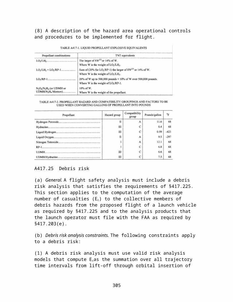
being subjected to the effects of a moist, salt-laden atmosphere. The test or analysis must demonstrate the ability of all externally exposed surfaces to withstand a salt-fog environment. The test or analysis must demonstrate the ability of each internal part of a component to withstand a salt-fog environment unless the component is environmentally sealed, and acceptance testing verifies that the seal works.
(i) Fine sand. For a component that will be exposed to fine sand or dust, a fine sand test or analysis must demonstrate that the component satisfies all its performance specifications after being subjected to the effects of dust or fine sand particles that may penetrate into cracks, crevices, bearings and joints. The test or analysis must demonstrate the ability of all externally exposed surfaces to withstand a fine sand environment. The test or analysis must demonstrate the ability of each internal part of a component to withstand a fine sand environment unless the component is environmentally sealed and acceptance testing verifies that the seal works.
(j) Tensile load. A tensile load test must demonstrate that a component satisfies all its performance specifications after being exposed to tensile and compression loads of no less than twice the maximum predicted level during transportation and installation. In addition, the test load must satisfy one of the following where applicable:
(1) For an explosive transfer system and its associated fittings, a pull of no less than 100 pounds unless the launch operator establishes procedural controls or tests that prevent or detect mishandling;
(2) For a destruct charge and its associated fittings, a pull of no less than 50 pounds;
(3) For a flight radio frequency connector, a pull of no less than one-half the manufacturer specified limit;
(4) For an electro-explosive device wire, a pull of no less than 18 pounds; or
(5) For an electrical pin of an exploding bridgewire device, no less than an 18-pound force in axial and compression modes.
(k) Handling drop of ordnance. A handling drop test must demonstrate that an ordnance component satisfies all its performance specifications after experiencing the more severe of the following:
(1) The maximum predicted drop and resulting impact that could occur and go undetected during storage, transportation, or installation; or
(2) A six-foot drop onto a representative surface in any orientation that could occur during storage, transportation, or installation.
(l) Abnormal drop of ordnance. An abnormal drop test must demonstrate that an ordnance component does not initiate and allows for safe disposal after experiencing the
305
maximum predicted drop and resulting impact onto a representative surface in any orientation, that could occur during storage, transportation, or installation. The component need not function after this drop.
E417.11 Qualification operating environments
(a) General. This section applies to each qualification operating environment test or analysis identified by any table of this appendix. A qualification operating environment test must demonstrate that a component satisfies all of its performance specifications when subjected to each qualification operating environment including each physical environment that the component will experience during acceptance testing, launch countdown, and flight. The test must employ each margin required by this section.
(b) Qualification sinusoidal vibration. (1) A qualification sinusoidal vibration test or analysis of a component must demonstrate that the component and each connection to any item that attaches to the component satisfy all their performance specifications when subjected to the qualification sinusoidal vibration environment. The attached items must include any vibration or shock isolator, grounding strap, bracket, explosive transfer system, or cable to the first tie-down. Any cable that interfaces with the component during any test must be representative of the cable used for flight.
(2) The qualification sinusoidal vibration environment must be no less than 6dB greater than the maximum predicted sinusoidal vibration environment for no less than three times the maximum predicted duration.
(3) The sinusoidal frequency must range from 50% lower than the maximum predicted frequency range to 50% higher than the maximum predicted frequency range.
(4) Any test must satisfy all of the following:
(i) The test must subject each of three mutually perpendicular axes of the component to the qualification sinusoidal vibration environment, one axis at a time. For each axis, the duration of the vibration must be no less than three times the maximum predicted sinusoidal vibration duration.
(ii) The sinusoidal sweep rate must be no greater than one-third the maximum predicted sweep rate;
(iii) The sinusoidal vibration test amplitude must have an accuracy of ±10%; and
(iv) For any component that uses one or more shock or vibration isolators, the component must undergo the test mounted on its isolator or isolators as a unit. Each isolator must satisfy the requirements of section E417.35.
306
(5) Any analysis must demonstrate that the qualification random vibration environment of paragraph (c) of this section encompasses the qualification sinusoidal vibration environment.
(c) Qualification random vibration. (1) A qualification random vibration test of a component must demonstrate that the component and each connection to any item that attaches to the component satisfy all their performance specifications when subjected to the qualification random vibration environment. The attached items must include any isolator, grounding strap, bracket, explosive transfer system, or cable to the first tie-down. Any cable that interfaces with the component during any test must be representative of the cable used for flight.
(2) For each component required by this appendix to undergo 100% acceptance testing, the minimum qualification random vibration environment must be no less than a 3 dB margin greater than the maximum acceptance random vibration test environment for all frequencies from 20 Hz to 2,000 Hz. The minimum and maximum test environments must account for all the test tolerances to ensure that the test maintains the 3 dB margin.
(3) For each component that is not required by this appendix to undergo 100% acceptance testing, the minimum qualification random vibration environment must be no less than a 4.5–dB margin greater than the greater of the maximum predicted random vibration environment or the minimum workmanship test levels of table E417.11–1 for all frequencies from 20 Hz to 2000 Hz. The minimum qualification test environment must account for all the test tolerances to ensure that the test maintains the 4.5 dB margin.
(4) If a component is mounted on one or more shock or vibration isolators during flight, the component must undergo the qualification random vibration test while hard-mounted or isolator-mounted as follows:
(i) Any qualification random vibration test with the component hard-mounted must subject the component to a qualification random vibration environment that:
(A) Accounts for the isolator attenuation and amplification due to the maximum predicted operating random vibration environment, including any thermal effects and acceleration pre-load performance variability, and adds a 1.5 dB margin to account for any isolator attenuation variability;
(B) Adds the required qualification random vibration margin of paragraph (c)(1) or (c)(2) of this section after accounting for the isolator effects of paragraph (c)(4)(i)(A) of this section and accounts for all tolerances that apply to the isolator's performance specifications to ensure that the qualification test margin is maintained; and
(C) Is no less than the minimum workmanship screening qualification random vibration level of table E417.11–1.
(ii) Any qualification random vibration test with the component isolator-mounted must:
307

(A) Use an isolator or isolators that passed the tests required by section E417.35;
(B) Have an input to each isolator of no less than the required qualification random vibration environment of paragraph (c)(1) or (c)(2) of this section; and
(C) Subject the component to no less than the minimum workmanship screening qualification random vibration level of table E417.11–1. If the isolator or isolators prevent the component from experiencing the minimum workmanship level, the component must undergo a test while hard-mounted that subjects the component to the workmanship level.
(5) The test must subject each component sample to the qualification random vibration environment in each of three mutually perpendicular axes. For each axis, the test must last three times as long as the acceptance test duration or a minimum workmanship qualification duration of 180 seconds, whichever is greater.
(6) For a component sample that must experience the acceptance random vibration environment before it experiences the qualification random vibration environment, such as a command receiver decoder, the test must use the same configuration and methods for the acceptance and qualification environments.
(7) If the duration of the qualification random vibration environment leaves insufficient time to complete any required performance verification test while the component is subjected to the full qualification environment, the test must continue at no less than the acceptance random vibration environment. The test need only continue for the additional time needed to complete the performance verification test.
(8) The test must continuously monitor and record all performance and status-of-health parameters while the component is subjected to the qualification environment. This monitoring must have a sample rate that will detect any component performance degradation. Any electrical component must undergo the test while subjected to its nominal operating voltage.
(9) A launch operator may substitute a random vibration test for another required dynamic test, such as acceleration, acoustic, or sinusoidal vibration if the launch operator demonstrates that the forces, displacements, and test duration imparted on a component during the random vibration test are no less severe than the other test environment.
308
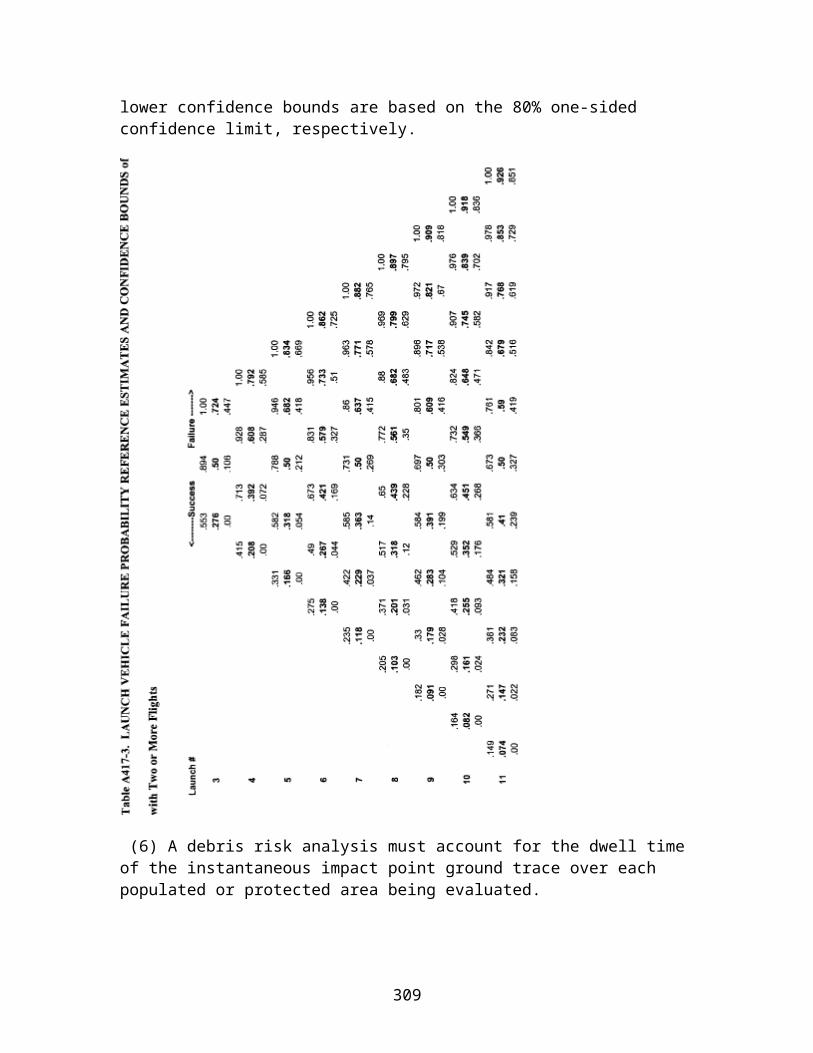
(d) Qualification acoustic. (1) A qualification acoustic vibration test or analysis of a component must demonstrate that the component and each connection to any item that attaches to the component satisfy all their performance specifications when subjected to the qualification acoustic vibration environment. The attached items must include any isolator, grounding strap, bracket, explosive transfer system, or cable to the first tie-down. Any cable that interfaces with the component during any test must be representative of the cable used for flight.
(2) For each component required by this appendix to undergo 100% acoustic acceptance testing, the minimum qualification acoustic vibration environment must be greater than the maximum acceptance acoustic vibration test environment for all frequencies from 20 Hz to 2000 Hz. The minimum and maximum test environments must account for all the test tolerances to ensure that the test maintains a positive margin between the minimum qualification environment and the maximum acceptance environment. For each acoustic vibration test required by this appendix to have a tolerance of ±3 dB, the qualification test level must be 6 dB greater than the acceptance test level.
(3) For each component that is not required by this appendix to undergo 100% acceptance testing, such as ordnance, the minimum qualification acoustic vibration environment must be no less than a 3 dB margin greater than the maximum predicted acoustic vibration environment or a minimum workmanship screening test level of 144 dBA for all frequencies from 20 Hz to 2000 Hz. The minimum qualification test environment must account for all the test tolerances to ensure that the test maintains the 3 dB margin. For each acoustic vibration test required by this appendix to have a tolerance of ±3.0 dB, the qualification test level must be 6 dB greater than the greater of the maximum predicted environment or the minimum workmanship test level.
(4) For any component that uses one or more shock or vibration isolators during flight, the component must undergo any qualification acoustic vibration test mounted on its isolator or isolators as a unit. Each isolator must satisfy the test requirements of section E417.35.
309

(5) Any test must continuously monitor and record all performance and status-of-health parameters while the component is subjected to the qualification environment. This monitoring must have a sample rate that will detect any component performance degradation.
(6) Any analysis must demonstrate that the qualification random vibration test environment of paragraph (c) of this section encompasses the qualification acoustic vibration environment. The analysis must demonstrate that the qualification random vibration environment is more severe than the qualification acoustic vibration environment. The analysis must account for all peak vibration levels and durations.
(e) Qualification shock. (1) A qualification shock test of a component must demonstrate that the component and each connection to any item that attaches to the component satisfies all their performance specifications when subjected to the qualification shock environment. The attached items must include any isolator, grounding strap, bracket, explosive transfer system, or cable to the first tie-down. Any cable that interfaces with the component during the test must be representative of the cable used for flight.
(2) The minimum qualification shock environment must be no less than a 3 dB margin plus the greater of the maximum predicted environment or the minimum breakup levels identified in table E417.11–2 for all frequencies from 100 Hz to 10000 Hz. The minimum qualification test environment must account for all the test tolerances to ensure that the test maintains the 3dB margin. For a shock test required by this appendix to have a ±3 dB tolerance, the qualification test environment must be 6 dB greater than the greater of the maximum predicted shock environment or the minimum breakup test level.
(3) The test must subject the component simultaneously to a shock transient and all the required frequencies.
(4) The test must subject each component to three shocks in each direction along each of the three orthogonal axes.
(5) The shock must last as long as the maximum predicted shock event.
(6) The test must continuously monitor each component's critical performance parameters for any discontinuity or inadvertent output while the component is subjected to the shock environment.
(7) The test must continuously monitor and record all performance and status-of-health parameters while the component is subjected to the qualification environment. This monitoring must have a sample rate of once every millisecond or better.
(8) For any component that uses one or more shock or vibration isolators during flight, the component must undergo the qualification shock test mounted on its isolator or isolators. Each isolator must satisfy the test requirements of section E417.35.
310

(f) Qualification acceleration. (1) A qualification acceleration test or analysis of a component must demonstrate that the component and each connection to any item that attaches to the component satisfy all their performance specifications when subjected to the qualification acceleration environment. The attached items must include any isolator, grounding strap, bracket, explosive transfer system, or cable to the first tie-down. Any cable that interfaces with the component during any test must be representative of the cable used for flight.
(2) The qualification acceleration test environment must be no less than 200% greater than the maximum predicted acceleration environment.
(3) The qualification acceleration must last three times as long as the maximum predicted environment lasts in each direction for each of the three orthogonal axes.
(4) For any test, if the test tolerance is more than ±10%, the qualification acceleration test environment of paragraph (f)(1) of this section must account for the test tolerance to ensure that the test maintains the 200% margin between the minimum qualification acceleration test and the maximum predicted environment.
(5) Any analysis must demonstrate that the qualification operating random vibration test required by paragraph (c) of this section encompasses the qualification acceleration environment. The analysis must demonstrate that the qualification random vibration environment is equal to or more severe than the qualification acceleration environment. The analysis must account for the peak vibration and acceleration levels and durations.
(6) Any test must continuously monitor and record all performance and status-of-health parameters while the component is subjected to the qualification environment. This monitoring must have a sample rate that will detect any component performance degradation.
(7) For any component that uses one or more shock and vibration isolators during flight, the component must undergo any qualification acceleration test mounted on its isolator or isolators. Each isolator must satisfy the test requirements of section E417.35.
311
(g) Qualification humidity. A qualification humidity test or analysis must demonstrate that a component satisfies all its performance specifications when subjected to the maximum predicted relative humidity environment that the component could experience when stored, transported, or installed as follows:
(1) The test or analysis must demonstrate the ability of all externally exposed surfaces to withstand the maximum predicted relative humidity environment.
(2) The test or analysis must demonstrate the ability of each internal part of a component to withstand the maximum predicted relative humidity environment unless the component is environmentally sealed and an acceptance test demonstrates that the seal works.
(3) Each test must satisfy all of the following:
(i) The test must subject the component to no less than four thermal cycles while the component is exposed to a relative humidity of no less than 95%;
(ii) The test must measure each electrical performance parameter at the cold and hot temperatures during the first, middle and last thermal cycles; and
(iii) The test must continuously measure and record all performance and status-of-health parameters with a resolution and sample rate that will detect any component performance degradation throughout each thermal cycle.
(h) Qualification thermal cycle. A qualification thermal cycle test must demonstrate that a component satisfies all its performance specifications when subjected to the qualification thermal cycle environment as follows:
(1) Electronic components. For any command receiver decoder or other electronic component that contains piece-part circuitry, such as microcircuits, transistors, diodes and relays, a qualification thermal cycle test must satisfy all of the following:
(i) The qualification thermal cycle environment must range from 10 °C above the acceptance test high temperature to 10 °C below the acceptance test low temperature;
(ii) The test must subject a component to no less than three times the acceptance-number of thermal cycles. For each component, the acceptance-number of thermal cycles must satisfy section E417.13(d)(1). For each cycle, the dwell-time at each of the high and low temperatures must last long enough for the component to achieve internal thermal equilibrium and must last no less than one hour. The test must begin each dwell-time at each high and low temperature with the component turned off. The component must remain off until the temperature stabilizes. Once the temperature stabilizes, the component must be turned on and the test must complete each dwell-time with the component turned on;
312

(iii) When heating or cooling the component, the temperature must change at an average rate of 1 °C per minute or the maximum predicted rate, whichever is greater;
(iv) The test must measure all performance parameters with the component powered at its low and high operating voltages when the component is at ambient temperature before beginning the first thermal cycle and after completing the last cycle. The test must measure all performance parameters with the component powered at its low and high operating voltages when the component is at the high and low temperatures during the first, middle, and last thermal dwell cycles; and
(v) The test must continuously monitor and record all critical performance and status-of-health parameters during all cycles and thermal transitions and with the component operating at its nominal operating voltage. The monitoring and recording must have a resolution and sample rate that will detect any component performance degradation.
(2) Passive components. For any passive component that does not contain an active electronic piece-part, such as a radio frequency antenna, coupler, or cable, a qualification thermal cycle test must satisfy all of the following:
(i) The qualification thermal cycle environment must range from 10 °C above the acceptance test high temperature to 10 °C below the acceptance test low temperature;
(ii) The test must subject a component to no less than three times the acceptance-number of thermal cycles. For each component, the acceptance-number of thermal cycles must satisfy section E417.13(d)(1). For each cycle, the dwell-time at each high and low temperature must last long enough for the component to achieve internal thermal equilibrium and must last no less than one hour;
(iii) When heating or cooling the component, the temperature must change at an average rate of 1 °C per minute or the maximum predicted rate, whichever is greater;
(iv) The test must measure all performance parameters when the component is at ambient temperature before beginning the first thermal cycle and after completing the last cycle. The test must measure all performance parameters when the component is at the high and low temperatures during the first, middle, and last thermal cycles; and
(v) The test must continuously monitor and record all critical performance and status-of-health parameters with a resolution and sample rate that will detect any component performance degradation during all cycles and thermal transitions.
(3) Safe-and-Arm Devices. For any electro-mechanical safe-and-arm device with an internal explosive, a qualification thermal cycle test must satisfy all of the following:
(i) The qualification thermal cycle must range from 10 °C above the acceptance test high temperature to 10 °C below the acceptance test low temperature;
313
(ii) The test must subject the component to no less than three times the acceptance-number of thermal cycles. For each component, the acceptance-number of thermal cycles must satisfy section E417.13(d)(1). For each cycle, the dwell-time at each high and low temperature must last long enough for the component to achieve internal thermal equilibrium and must last no less than one hour;
(iii) When heating or cooling the component, the temperature must change at an average rate of 1 °C per minute or the maximum predicted rate, whichever is greater;
(iv) The test must measure all performance parameters when the component is at ambient temperature before beginning the first thermal cycle. The test must measure all performance parameters when the component is at the high and low temperatures during the first, middle, and last thermal cycles. The test must measure all performance parameters when the component is at ambient temperature after completing the last cycle; and
(v) The test must continuously monitor and record all critical performance and status-of-health parameters during all temperature cycles and transitions using a resolution and sample rate that will detect any component performance degradation.
(4) Ordnance components. For any ordnance component, a qualification thermal cycle test must satisfy all of the following:
(i) The qualification thermal cycle must range from 10 °C above the predicted highest temperature, or 71 °C, whichever is higher, to 10 °C below the predicted lowest temperature, or −54 °C, whichever is lower;
(ii) The test must subject each ordnance component to no less than the acceptance-number of thermal cycles. For each component, the acceptance-number of thermal cycles must satisfy section E417.13(d)(1). For an ordnance component that is used inside a safe-and-arm device, the test must subject the component to three times the acceptance-number of thermal cycles. For each cycle, the dwell-time at each high and low temperature must last long enough for the component to achieve internal thermal equilibrium and must last no less than two hours; and
(iii) When heating or cooling the component, the temperature must change at an average rate of 3 °C per minute or the maximum predicted rate, whichever is greater.
(i) Qualification thermal vacuum. A qualification thermal vacuum test or analysis must demonstrate that a component satisfies all its performance specifications, including structural integrity, when subjected to the qualification thermal vacuum environment as follows:
(1) The qualification thermal vacuum environment must satisfy all of the following:
314

(i) The thermal vacuum pressure gradient must equal or exceed the maximum predicted rate of altitude change that the component will experience during flight;
(ii) The final vacuum dwell-time must last long enough for the component to achieve pressure equilibrium and equal or exceed the greater of the maximum predicted dwell-time or 12 hours;
(iii) During the final vacuum dwell-time, the environment must include no less than three times the maximum predicted number of thermal cycles; and
(iv) Each thermal cycle must range from 10 °C above the acceptance thermal vacuum range, to 10 °C below the acceptance thermal vacuum range. The acceptance thermal vacuum temperature range is described in section E417.13(e);
(2) Any test must satisfy all of the following:
(i) The test must measure all performance parameters with the component powered at its low and high operating voltages when the component is at ambient temperature before beginning the first thermal cycle and after completing the last cycle;
(ii) The test must measure all performance parameters while the component is powered at its low and high operating voltages when the component is at the high and low temperatures during the first, middle and last thermal cycles;
(iii) The test must continuously monitor and record all critical performance and status-of-health parameters during chamber pressure reduction and the final vacuum dwell-time, with the component at its high operating voltage and using a resolution and sample rate that will detect any component performance degradation; and
(3) Any analysis must satisfy all of the following:
(i) For any low voltage component of less than 50 volts, the analysis must demonstrate that the component is not susceptible to corona, arcing, or structural failure; and
(ii) For any high voltage component of 50 volts or greater, the component must undergo a thermal vacuum test unless the component is environmentally sealed and the analysis demonstrates that any low voltage externally exposed part is not susceptible to corona, arcing, or structural failure. A component with any high voltage externally exposed part of 50 volts or greater must undergo a thermal vacuum test.
(j) Electromagnetic interference and electromagnetic compatibility. An electromagnetic interference and electromagnetic compatibility test must demonstrate that a component satisfies all its performance specifications when subjected to radiated or conducted emissions from all flight vehicle systems and external ground transmitter sources. In addition, the test must demonstrate that the component does not radiate or conduct
315
electromagnetic interference that would degrade the performance of any other flight termination system component.
(k) Explosive atmosphere. An explosive atmosphere test or analysis must demonstrate that a component is capable of operating in an explosive atmosphere without creating an explosion or that the component is not used in an explosive environment.
E417.13 Acceptance testing and analysis
(a) General. This section applies to each acceptance test or analysis identified by any table of this appendix. An acceptance test or analysis must demonstrate that a component does not have any material or workmanship defect that could adversely affect the component's performance and that the component satisfies all its performance specifications when subjected to each acceptance environment, including each workmanship and maximum predicted operating environment.
(1) An acceptance test of a component must subject the component to one or more of the component's maximum predicted environments as determined under section D417.7. An acceptance test must not subject a component to a force or environment that is not tested during qualification testing.
(2) Each component sample that is intended for flight must undergo each acceptance test identified by any table of this appendix. A single-use component, such as ordnance or a battery, must undergo the production lot sample acceptance tests identified by any tables of this appendix.
(3) If a launch vehicle uses a previously flown and recovered flight termination system component, the component must undergo one or more reuse acceptance tests before each next flight to demonstrate that the component still satisfies all its performance specifications when subjected to each maximum predicted environment. Each reuse acceptance test must be the same as the initial acceptance test for the component's first flight. Each reuse acceptance test must follow a written component reuse qualification, refurbishment, and acceptance plan and procedures. Each acceptance reuse test must compare performance parameter measurements taken during the test to all previous acceptance test measurements to ensure that the data show no trends that indicate any degradation in performance that could prevent the component from satisfying all its performance specifications during flight.
(4) Each acceptance test of a component must use test tolerances that are consistent with the test tolerances used by each qualification test of the component.
(b) Acceptance random vibration. An acceptance random vibration test must demonstrate that a component satisfies all its performance specifications when exposed to the acceptance random vibration environment as follows:
316

(1) The acceptance random vibration environment must equal or exceed the greater of the maximum predicted random vibration level or the minimum workmanship acceptance test level of table E417.13–1, for all frequencies from 20 Hz to 2000 Hz, in each of three mutually perpendicular axes.
(2) For each axis, the vibration must last the greater of three times the maximum predicted duration or a minimum workmanship screening level of 60 seconds.
(3) For a component sample that undergoes qualification testing and must experience the acceptance environment before it experiences the qualification environment, such as a command receiver decoder, the test must use the same configuration and methods for the acceptance and qualification random vibration environments. An acceptance random vibration test of a flight component sample must use a configuration and method that is representative of the component's qualification tests to ensure that the requirements of paragraph (a) of this section are satisfied.
(4) For any component that is mounted on one or more vibration or shock isolators during flight, the component must undergo the acceptance random vibration test in the same isolator-mounted configuration or hard-mounted configuration as the component's qualification random vibration test as follows:
(i) Any hard-mounted acceptance random vibration test must subject the component to an acceptance random vibration environment that:
(A) Accounts for the isolator attenuation and amplification due to the maximum predicted operating random vibration environment, including any thermal effects and acceleration pre-load performance variability, and adds a 1.5 dB margin to account for any isolator attenuation variability; and
(B) Is no less than the minimum workmanship screening acceptance random vibration level of table E417.13–1.
(ii) Any isolator-mounted acceptance random vibration test must:
(A) Use an isolator or isolators that passed the tests required by section E417.35;
(B) Have an input to each isolator of no less than the required acceptance random vibration environment of paragraphs (b)(1) and (b)(2) of this section; and
(C) Subject the component to no less than the minimum workmanship screening acceptance random vibration level of table E417.13–1. If the isolator or isolators prevent the component from experiencing the minimum workmanship level, the component must undergo a hard-mount test that subjects the component to the workmanship level.
(5) If the duration of the acceptance random vibration environment leaves insufficient time to complete any required performance verification test while the component is
317
subjected to the full acceptance environment, the test must continue at no lower than 6 dB below the acceptance environment. The test need only continue for the additional time needed to complete the performance verification test.
(6) The test must continuously monitor all performance and status-of-health parameters with any electrical component at its nominal operating voltage. This monitoring must have a sample rate that will detect any component performance degradation.
(c) Acceptance acoustic vibration. An acceptance acoustic vibration test or analysis must demonstrate that a component satisfies all its performance specifications when exposed to the acceptance acoustic vibration environment as follows:
(1) The acceptance acoustic vibration environment must satisfy all of the following:
(i) The vibration level must equal or exceed the maximum predicted acoustic level for all frequencies from 20 Hz to 2,000 Hz in each of three mutually perpendicular axes; and
(ii) For each axis, the vibration must last the maximum predicted duration or 60 seconds, whichever is greater.
(2) Any test must satisfy all of the following:
(i) The test must continuously monitor all performance and status-of-health parameters with any electrical component at its nominal operating voltage. This monitoring must have a sample rate that will detect any component performance degradation; and
(ii) If the duration of the acceptance acoustic vibration environment leaves insufficient time to complete any required performance verification test while the component is subjected to the full acceptance environment, the test must continue at no lower than 6 dB below the acceptance environment. The test need only continue for the additional time needed to complete the performance verification test.
318

(3) Any analysis must demonstrate that the acceptance random vibration environment of paragraph (b) of this section encompasses the acceptance acoustic vibration environment. The analysis must demonstrate that the peak acceptance random vibration levels and duration are equal to or are more severe than the acceptance acoustic vibration environment.
(d) Acceptance thermal cycle. An acceptance thermal cycle test of a component must demonstrate that the component satisfies all its performance specifications when exposed to the acceptance thermal cycle environment as follows:
(1) Acceptance-number of thermal cycles. The acceptance-number of thermal cycles for a component means the number of thermal cycles that the component must experience during the test. The test must subject each component to no less than the greater of eight thermal cycles or 1.5 times the maximum number of thermal cycles that the component could experience during launch processing and flight, including all launch delays and recycling, rounded up to the nearest whole number.
(2) Electronic components. For any electronic component, an acceptance thermal cycle test must satisfy all of the following:
(i) The acceptance thermal cycle environment must range from the higher of the maximum predicted environment high temperature or 61 °C workmanship screening level, to the lower of the predicted low temperature or a −24 °C workmanship screening level.
(ii) The test must subject a component to no fewer than 10 plus the acceptance-number of thermal cycles. For each component, the acceptance-number of thermal cycles must satisfy this paragraph. For each cycle, the dwell-time at each high and low temperature must last long enough for the component to achieve internal thermal equilibrium and must last no less than one hour. The test must begin each dwell-time at each high and low temperature with the component turned off. The component must remain off until the temperature stabilizes. Once the temperature stabilizes, the test must complete each dwell-time with the component turned on.
(iii) When heating or cooling the component, the temperature must change at an average rate of 1 °C per minute or the maximum predicted rate, whichever is greater.
(iv) The test must measure all performance parameters with the component powered at its low and high operating voltages when the component is at ambient temperature before beginning the first thermal cycle and after completing the last cycle.
(v) The test must measure all performance parameters with the component at its low and high operating voltages when the component is at the high and low temperatures during the first, middle, and last thermal cycles.
319

(vi) The test must continuously monitor and record all critical performance and status-of-health parameters during all cycles and thermal transitions and with the component at its nominal operating voltage. The monitoring and recording must have a resolution and sample rate that will detect any component performance degradation.
(3) Passive components. For any passive component that does not contain any active electronic piece-part, such as any radio frequency antenna, coupler, or cable, an acceptance thermal cycle test must satisfy all of the following:
(i) Unless otherwise noted, the acceptance thermal cycle environment must range from the higher of the maximum predicted environment high temperature or a 61 °C workmanship screening temperature, to the lower of the predicted lowest temperature or a −24 °C workmanship screening temperature;
(ii) The test must subject a component to no fewer than the acceptance-number of thermal cycles. For each component, the acceptance-number of thermal cycles must satisfy this paragraph. For each cycle, the dwell-time at each high and low temperature must last long enough for the component to achieve internal thermal equilibrium and must last no less than one hour;
(iii) When heating or cooling the component, the temperature must change at an average rate of 1 °C per minute or the maximum predicted rate, whichever is greater;
(iv) The test must measure all performance parameters when the component is at ambient temperature before beginning the first thermal cycle and after completing the last cycle;
(v) The test must measure all performance parameters when the component is at the high and low temperatures during the first, middle, and last thermal cycles; and
(vi) The test must continuously monitor and record all critical performance and status-of-health parameters throughout each thermal cycle with a resolution and sample rate that will detect any component performance degradation.
(4) Safe-and-arm devices. For any electro-mechanical safe-and-arm device with an internal explosive, an acceptance thermal cycle test must satisfy all of the following:
(i) The acceptance thermal cycle environment must range from the higher of the maximum predicted environment high temperature or the minimum workmanship screening temperature of 61 °C to the lower of the predicted lowest temperature or the minimum workmanship screening temperature of −24 °C.
(ii) The test must subject a component to no fewer than the acceptance-number of thermal cycles. For each component, the acceptance-number of thermal cycles must satisfy this paragraph. For each cycle, the dwell-time at each high and low temperature must last long enough for the component to achieve internal thermal equilibrium and must last no less than one hour.
320

(iii) When heating or cooling the component, the temperature must change at an average rate of 1 °C per minute or the maximum predicted rate, whichever is greater.
(iv) The test must measure all performance parameters when the component is at ambient temperature before beginning the first thermal cycle and after completing the last cycle.
(v) The test must measure all performance parameters including each critical electrical parameter, when the component is at the high and low temperatures during the first, middle, and last thermal cycles.
(vi) The test must continuously monitor and record all critical performance and status-of-health parameters throughout each thermal cycle with a resolution and sample rate that will detect whether the component satisfies all its performance specifications.
(e) Acceptance thermal vacuum. An acceptance thermal vacuum test or analysis must demonstrate that a component satisfies all its performance specifications when exposed to the acceptance thermal vacuum environment as follows:
(1) The acceptance thermal vacuum environment must satisfy all of the following:
(i) The thermal vacuum pressure gradient must equal or exceed the maximum predicted rate of altitude change that the component will experience during flight. The pressure gradient must allow for no less than ten minutes for reduction of chamber pressure at the pressure zone from ambient pressure to 20 Pascal;
(ii) The final vacuum dwell-time must last long enough for the component to achieve pressure equilibrium and must last no less than the maximum predicted dwell-time or 12 hours, whichever is greater;
(iii) During the final vacuum dwell-time, the environment must include no less than the maximum predicted number of thermal cycles; and
(iv) Each thermal cycle must range from the higher of the maximum predicted environment high temperature or the workmanship screening high temperature of 61 °C, to the lower of the predicted low temperature or the workmanship screening low temperature of −24 °C.
(2) Any test must satisfy all of the following:
(i) The test must measure all performance parameters with the component powered at its low and high operating voltages when the component is at ambient temperature before beginning the first thermal cycle and after completing the last cycle.
(ii) The test must measure all performance parameters with the component powered at its low and high operating voltages when the component is at the high and low temperatures during the first, middle, and last thermal cycles; and
321

(iii) The test must continuously monitor all critical performance and status-of-health parameters during chamber pressure reduction and during the final vacuum dwell-time with the component at its high operating voltage. This monitoring must have a resolution and sample rate that will detect any component performance degradation.
(3) Any analysis must satisfy all of the following:
(i) For any low voltage component of less than 50 volts, any analysis must demonstrate that the component is not susceptible to corona, arcing, or structural failure; and
(ii) Any high voltage component of 50 volts or greater must undergo a thermal vacuum test unless the component is environmentally sealed and the analysis demonstrates that any low voltage externally exposed part of less than 50 volts is not susceptible to corona, arcing, or structural failure. A component with any high voltage externally exposed part must undergo an acceptance thermal vacuum test.
(f) Tensile loads. An acceptance tensile load test of a component must demonstrate that the component is not damaged and satisfies all its performance specifications after experiencing twice the maximum predicted pull-force that the component could experience before, during, or after installation.
E417.15 Ordnance service-life extension testing
(a) General. This section applies to each service-life extension test of an ordnance component that is identified by any table of this appendix. A service-life extension test must demonstrate that an ordnance component will satisfy all its performance specifications when subjected to non-operating and operating environments throughout its initial service-life and throughout any extension to the service-life. An ordnance component must undergo a service-life extension test to extend its service-life if its initial service-life and any previous extension will expire before the component is used for flight.
(b) Service-life. An ordnance component must undergo any service-life extension test before the component's initial service-life expires and again before each service-life extension expires. The initial service-life of an ordnance component, including any component that contains ordnance or is used to directly initiate ordnance, must start upon completion of the initial production lot sample acceptance tests and must include both storage time and time after installation until completion of flight. The test tables of this appendix identify the options for the length of any service-life extension for each type of ordnance component.
(c) Test samples. The tables of this appendix identify the number of ordnance component samples that must undergo any service-life extension test. Each component sample must be:
(i) From the same production lot;
322

(ii) Consist of identical parts and materials;
(iii) Manufactured through identical processes; and
(iv) Stored with the flight ordnance component or in an environment that duplicates the storage conditions of the flight ordnance component.
E417.17 Radio frequency receiving system
(a) General. (1) This section applies to a radio frequency receiving system, which includes each flight termination system antenna and radio frequency coupler and any radio frequency cable or other passive device used to connect a flight termination system antenna to a command receiver.
(2) The components of a radio frequency receiving system must satisfy each test or analysis identified by any table of this section to demonstrate that:
(i) The system is capable of delivering command control system radio frequency energy to each flight termination system receiver; and
(ii) The system satisfies all its performance specifications when subjected to each non-operating and operating environment and any performance degradation source. Such sources include any command control system transmitter variation, non-nominal launch vehicle flight condition, and flight termination system performance variation.
323

324

325
(b) Status-of-health . A status-of-health test of a radio frequency receiving system must satisfy section E417.3(f) and include antenna voltage standing wave ratio testing that measures the assigned operating frequency at the high and low frequencies of the operating bandwidth to verify that the antenna satisfies all its performance specifications.
(c) Link performance . A link performance test of a radio frequency component or subsystem must demonstrate that the component or subsystem satisfies all its performance specifications when subjected to performance degradation caused by ground transmitter variations and non-nominal vehicle flight. This must include demonstrating all of the following:
(1) The radio frequency receiving system provides command signals to each command destruct receiver at an electromagnetic field intensity of 12 dB above the level required
326
for reliable receiver operation over 95% of the antenna radiation sphere surrounding the launch vehicle;
(2) The radio frequency coupler insertion loss and voltage standing wave ratio at the assigned operating frequency and at the high and low frequencies of the operating bandwidth satisfy all their performance specifications; and
(3) The cable insertion loss at the assigned operating frequency and at the high and low frequencies of the operating bandwidth satisfies all its performance specifications.
(d) Isolation . An isolation test of a radio frequency receiving system must demonstrate that each of the system's radio frequency couplers isolate the redundant antennas and receiver decoders from one another. The test must demonstrate that an open or short-circuit in one string of the redundant system, antenna or receiver decoder, will not prevent functioning of the other side of the redundant system. The test must demonstrate that the system satisfies all its performance specifications for isolation and is in-family.
(e) Abbreviated status-of-health . An abbreviated status-of health test of a radio frequency receiving system component must determine any internal anomaly while the component is under environmental stress conditions. The test must include continuous monitoring of the voltage standing wave ratio and any other critical performance parameter that indicates an internal anomaly during environmental testing to detect any variations in amplitude. Any amplitude variation constitutes a test failure. The monitoring must have a sample rate that will detect any component performance degradation.
(f) Antenna pattern . An antenna pattern test must demonstrate that the radiation gain pattern of the entire radio frequency receiving system, including the antenna, radio frequency cables, and radio frequency coupler will satisfy all the system's performance specifications during vehicle flight. This must include all of the following:
(1) The test must determine the radiation gain pattern around the launch vehicle and demonstrate that the system is capable of providing command signals to each command receiver decoder with electromagnetic field intensity at a 12 dB link margin above the level required for reliable receiver operation. The test must demonstrate the 12–dB margin over 95 percent of the antenna radiation sphere surrounding the launch vehicle.
(2) All test conditions must emulate flight conditions, including ground transmitter polarization, using a simulated flight vehicle and a flight configured radio frequency command destruct system.
(3) The test must measure the radiation gain for 360 degrees around the launch vehicle in degree increments that are small enough to identify any deep pattern null and to verify that the required 12 dB link margin is maintained throughout flight. Each degree increment must not exceed two degrees.
327
(4) The test must generate each antenna pattern in a data format that is compatible with the format needed to perform the flight safety system radio frequency link analysis required by §417.329(h).
(g) Abbreviated antenna pattern . An abbreviated antenna pattern test must determine any antenna pattern changes that might have occurred due to damage to an antenna resulting from exposure to test environments. This must include all of the following:
(1) The antenna must undergo the test before and after exposure to the qualification or acceptance test environments.
(2) The test must use a standard ground plane test fixture. The test configuration need not generate antenna pattern data that is representative of the actual system-level patterns.
(3) The test must include gain measurements in the 0° and 90° plane vectors and a conical cut at 80°.
E417.19 Command receiver decoder
(a) General . A command receiver decoder must satisfy each test or analysis identified by any table of this section to demonstrate that the receiver decoder satisfies all its performance specifications when subjected to each non-operating and operating environment and any command control system transmitter variation.
328
329

330

331
(b) Status-of-health . A status-of-health test of a command receiver decoder must satisfy section E417.3(f) and must measure each pin-to-pin and pin-to-case resistance, input current, voltage standing wave ratio, and radio frequency threshold sensitivity. Each measurement must demonstrate that all wiring and connectors are installed according to the manufacturer's design. The test must demonstrate that each pin-to-pin and pin-to-case resistance satisfies its performance specification and is in-family.
332

(c) Functional performance . A functional performance test must demonstrate that a command receiver decoder satisfies all the requirements for an electronic component of section D417.27 that apply to the receiver decoder. This test must:
(1) Response time . Demonstrate that the receiver decoder satisfies all its performance specifications for response time, from receipt of destruct sequence to initiation of destruct output;
(2) Input current . Monitor the input current into the receiver decoder to demonstrate reliable functioning of all internal components. The test must demonstrate that the receiver decoder's electrical characteristics satisfy all its performance specifications and are in-family;
(3) Leakage current . Demonstrate that the maximum leakage current through any command output port is at a level that cannot degrade performance of down-string electrical or ordnance initiation systems or result in an unsafe condition. The test must demonstrate no less than a 20–dB safety margin between the receiver leakage output and the lowest level that could degrade performance of down-string electrical or ordnance initiation systems or result in an unsafe condition;
(4) Output Functions . Function all receiver outputs to demonstrate that all the output performance specifications are satisfied. The test must include drawing the expected current at the receiver's low, nominal and high input specified voltages using output impedances that simulate the flight-configured load. The test must demonstrate that a command receiver is capable of simultaneously outputting arm, destruct, and check channel signals; and
(5) Warm Up Time . Demonstrate that the receiver decoder satisfies all its performance specifications after being powered for the manufacturer specified warm-up time.
(d) Circuit protection . A circuit protection test must demonstrate that a receiver decoder's circuit protection provides for the receiver decoder to satisfy all its performance specifications when subjected to any improper launch processing, abnormal flight condition, or any non-flight termination system vehicle component failure. This test must:
(1) Abnormal voltage . Demonstrate that any circuit protection allows the receiver decoder to satisfy all its performance specifications when powered with the open circuit voltage of the receiver decoder's power source for no less than twice the expected duration of the open circuit voltage and then when powered with the minimum input voltage of the loaded voltage of the power source for no less than twice the expected duration of the loaded voltage. The test must also demonstrate that the receiver decoder satisfies all its performance specifications when subjected to increasing voltage from zero volts to the nominal voltage and then decreasing voltage from nominal back to zero;
333
(2) Power dropout . Demonstrate that, in the event of an input power dropout, any control or switching circuit that contributes to the reliable operation of a receiver decoder, including solid-state power transfer switches, does not change state for 50 milliseconds or more;
(3) Watchdog circuits . Demonstrate that any watchdog circuit satisfies all its performance specifications;
(4) Output circuit protection . Demonstrate that the receiver decoder's performance does not degrade when any of its monitoring circuits or non-destruct output ports are subjected to a short circuit or the highest positive or negative voltage capable of being supplied by the monitor batteries or other power supplies, for no less than five minutes;
(5) Reverse polarity . Demonstrate that the receiver decoder satisfies all of its performance specifications when subjected to a reverse polarity voltage that could occur before flight, for no less than five minutes; and
(6) Memory . Demonstrate by test or analysis that any memory device that is part of the receiver decoder satisfies all its performance specifications. The test or analysis must demonstrate that the data stored in memory is retained in accordance with the performance specifications. For any secure receiver decoder, the test or analysis must demonstrate that the command codes remain in memory for the specified time interval while the receiver decoder is not powered.
(e) Radio frequency processing.
(1) General . A radio frequency processing test must demonstrate that a receiver decoder's radio frequency processing satisfies all its performance specifications when subjected to command control system transmitting equipment tolerances and flight generated signal degradation. The environment must include locally induced radio frequency noise sources, vehicle plume, the maximum predicted noise-floor, ground transmitter performance variations, and abnormal launch vehicle flight.
(2) Tone-based system . For any tone-based system, a radio frequency processing test must demonstrate that the receiver decoder satisfies all the design requirements of section D417.29(b) of appendix D of this part and must satisfy all of the following;
(i) Decoder channel deviation . The test must demonstrate that the receiver decoder reliably processes the intended tone deviated signal at the minimum and maximum number of expected tones. The test must demonstrate that the receiver decoder satisfies all its performance specifications when subjected to a nominal tone deviation plus twice the maximum and minus half the minimum of the total combined tolerances of all applicable radio frequency performance factors. The tone deviation must be no less than ± 3 KHz per tone.
334

(ii) Operational bandwidth . The testing must demonstrate that the receiver decoder satisfies all its performance specifications at twice the worst-case command control system transmitter radio frequency shift, Doppler shifts of the carrier center frequency, and shifts in flight hardware center frequency during flight at the manufacturer guaranteed receiver sensitivity. The test must demonstrate an operational bandwidth of no less than ± 45KHz. The test must demonstrate that the operational bandwidth accounts for any tone deviation and that the receiver sensitivity does not vary by more than 3dB across the bandwidth.
(iii) Radio frequency dynamic range . The test must demonstrate that the receiver decoder satisfies all its performance specifications when subjected to variations of the radio frequency input signal level that it will experience during checkout and flight. The test must subject the receiver decoder to no less than five uniformly distributed radio frequency input levels. The test must demonstrate that the receiver outputs the destruct command from the radio frequency threshold level up to:
(A) The maximum radio frequency level that it will experience from the command control system transmitter during checkout and flight plus a 3 dB margin; or
(B) 13 dBm, whichever is greater.
(iv) Capture ratio . The test must demonstrate that the receiver cannot be captured by another transmitter with less than 80% of the power of the command transmitter system for the launch. The test must show that the application of any unmodulated radio frequency at a power level of up to 80% of the command control system transmitter's modulated carrier signal does not capture the receiver or interfere with a signal from the command control system.
(v) Radio frequency monitor . The test must demonstrate that the receiver decoder's monitoring circuit accurately monitors and outputs the strength of the radio frequency input signal and must satisfy all of the following:
(A) The test must show that the output of the monitor circuit is directly related and proportional to the strength of the radio frequency input signal from the threshold level to saturation.
(B) The dynamic range of the radio frequency input from the threshold level to saturation must be no less than 50 dB. The monitor circuit output from threshold to saturation must have a corresponding range that is greater than 18 dB.
(C) The test must perform periodic samples sufficient to demonstrate that the monitor satisfies all its performance specifications.
(D) The test must include the following radio frequency input levels: Quiescent; threshold; manufacturer guaranteed; beginning of saturation; and 13 dBm.
335

(E) The test must demonstrate that the slope of the monitor circuit output does not change polarity.
(vi) Radio frequency threshold sensitivity . The test must determine the radio frequency threshold sensitivity or each receiver decoder output command to demonstrate reliable radio frequency processing capability. The threshold sensitivity values must satisfy all their performance specifications, be repeatable, and be in-family. In-family performance may be met with a tolerance of ± dB.
(vii) Noise level margin . The test must demonstrate that the receiver decoder's guaranteed input sensitivity is no less than 6 dB higher than the maximum predicted noise-floor.
(viii) Voltage standing wave ratio . The test must demonstrate that any radio frequency losses within the receiver decoder interface to the antenna system satisfy the required 12 dB margin. The test must determine the radio frequency voltage standing wave ratio at the high, low, and assigned operating frequencies of the operating bandwidth and demonstrate that it satisfies its performance specifications and is in-family. The test must also demonstrate that the impedance of the radio frequency receiving system and the impedance of the receiver decoder are matched closely enough to ensure that the receiver decoder satisfies all its performance specifications.
(ix) Decoder channel bandwidth . The test must demonstrate that the receiver decoder provides for reliable recognition of any command signal when subjected to variations in ground transmitter tone frequency and frequency modulation deviation variations. The test must demonstrate that the receiver decoder satisfies all its performance specifications within the specified tone filter frequency bandwidth using a frequency modulated tone deviation from 2 dB to 20 dB above the measured threshold level.
(x) Tone balance . For any secure receiver decoder, the test must demonstrate that the receiver decoder can reliably decode a valid command with an amplitude imbalance between two tones within the same message.
(xi) Message timing . For any secure receiver decoder, the test must demonstrate that the receiver decoder functions reliably during any errors in timing caused by any ground transmitter tolerances. The test must demonstrate that the receiver decoder can process commands at twice the maximum and one-half the minimum timing specification of the ground system. These tolerances must include character dead-time, character on-time and inter-message dead-time.
(xii) Check tone . The test must demonstrate that the decoding and output of a tone, such as a pilot tone or check tone, is representative of link and command closure. The test must also demonstrate that the presence or absence of the tone signal will have no effect on the receiver decoder's command processing and output capability.
336

(xiii) Self-test . The test must demonstrate that the receiver decoder's self-test capability functions and satisfies all its performance specifications and does not inhibit functionality of the command destruct output. The test must include initiating the self-test while issuing valid command outputs.
(xiv) Reset . For any receiver decoder with a reset capability, the test must demonstrate that the reset will unlatch any command output that has been latched by a previous command.
(f) Inadvertent command output . Each of the following inadvertent command output tests must demonstrate that the receiver decoder does not provide an output other than when it receives a valid command.
(1) Dynamic stability . The test must demonstrate that the receiver decoder does not produce an inadvertent output when subjected to any radio frequency input short-circuit, open-circuit, or change in input voltage standing wave ratio.
(2) Out of band rejection . The test must demonstrate that the receiver decoder does not degrade in performance when subjected to any out-of-band vehicle or ground transmitter source that it could encounter from liftoff to the planned safe flight state. The test must ensure the receiver decoder does not respond to frequencies, from 10 MHz to 1000 MHz except at the receiver specified operational bandwidth. The test must demonstrate that the radio frequency rejection of out of band signals provides a minimum of 60 dB beyond eight times the maximum specified operational bandwidth. The test frequencies must include all expected interfering transmitting sources using a minimum bandwidth of 20% of each transmitter center frequency, receiver image frequencies and harmonics of the assigned center frequency.
(3) Decoder channel bandwidth rejection . The test must demonstrate that the receiver decoder rejects any out-of-band command tone frequency. The test must demonstrate that each tone filter will not respond to another tone outside the specified tone filter frequency bandwidth using a frequency modulated tone deviation from 2 dB to 20 dB above the measured threshold level.
(4) Adjacent tone decoder channel rejection . The test must demonstrate that none of the tone decoder channels responds to any adjacent frequency modulated tone channel when they are frequency modulated with a minimum of 150% of the expected tone deviation.
(5) Logic sequence . The test must demonstrate that the receiver issues the required commands when commanded and does not issue false commands during any abnormal logic sequence including issuing a destruct command prior to the arm command.
(6) Destruct sequence . The test must demonstrate that the receiver decoder requires two commanded steps to issue a destruct command. The test must demonstrate that the receiver processes an arm command as a prerequisite for the destruct command.
337

(7) Receiver abnormal logic . The test must demonstrate that the receiver decoder will not respond to any combination of tones or tone pairs other than the correct command sequence.
(8) Noise immunity . The test must demonstrate that a receiver decoder will not respond to a white noise frequency modulated radio frequency input at a minimum frequency modulated deviation of 12 dB above the measured threshold deviation.
(9) Tone drop . The test must demonstrate that the receiver decoder will not respond to a valid command output when one tone in the sequence is dropped.
(10) Amplitude modulation rejection . The test must demonstrate that the receiver decoder will not respond to any tone or amplitude modulated noise when subjected to maximum pre-flight and flight input power levels. An acceptance test must subject the receiver decoder to 50% amplitude modulation. A qualification test must subject the receiver decoder to 100% amplitude modulation.
(11) Decoder channel deviation rejection . The test must demonstrate that the receiver decoder does not inadvertently trigger on frequency-modulated noise. The test must demonstrate that the receiver decoder does not respond to tone modulations 10 dB below the nominal tone modulation.
(g) Input current monitor . An input current monitor test must continuously monitor command receiver decoder power input current during environmental stress conditions to detect any variation in amplitude. Any variation in input current indicates internal component damage and constitutes a test failure. Any fluctuation in nominal current draw when the command receiver decoder is in the steady state indicates internal component damage and constitutes a test failure.
(h) Output functions . An output functions test must subject the receiver decoder to the arm and destruct commands during environmental stress conditions and continuously monitor all command outputs to detect any variation in amplitude. Any variation in output level indicates internal component damage and constitutes a test failure.
(i) Radio frequency level monitor . A radio frequency level monitor test must subject a receiver decoder to the guaranteed radio frequency input power level during environmental stress conditions and continuously monitor the radio frequency level monitor, also known as radio frequency signal strength, signal strength telemetry output, or automatic gain control. Any unexpected fluctuations or dropout constitutes a test failure.
(j) Thermal performance . A thermal performance test must demonstrate that the receiver decoder satisfies all its performance specifications when subjected to operating and workmanship thermal environments. The receiver decoder must undergo the thermal performance test during a thermal cycle test and during a thermal vacuum test. The receiver decoder must undergo the thermal performance test at its low and high operating
338

voltage while the receiver decoder is at the high and low temperatures during the first, middle, and last thermal cycles. The thermal performance test at each high and low temperature must include each of the following sub-tests of this section:
(1) Response time, paragraph (c)(1) of this section;
(2) Input current, paragraph (c)(2) of this section;
(3) Output functions, paragraph (c)(4) of this section;
(4) Decoder channel deviation, paragraph (e)(2)(i) of this section;
(5) Operational bandwidth, paragraph (e)(2)(ii) of this section;
(6) Radio frequency dynamic range, paragraph (e)(2)(iii) of this section;
(7) Capture ratio, paragraph (e)(2)(iv) of this section;
(8) Radio frequency monitor, paragraph (e)(2)(v) of this section;
(9) Message timing, paragraph (e)(2)(xi) of this section;
(10) Check tone, paragraph (e)(2)(xii) of this section; and
(11) Self test, paragraph (e)(2)(xiii) of this section.
E417.21 Silver-zinc batteries
(a) General . This section applies to any silver-zinc battery that is part of a flight termination system. Any silver-zinc battery must satisfy each test or analysis identified by any table of this section to demonstrate that the battery satisfies all its performance specifications when subjected to each non-operating and operating environment.
339

340
341

342

343

344

345
(b) Cell capacity.
(1) Single electrical cycle. For a sample silver-zinc cell from a battery that has only one charge-discharge cycle, a capacity test must satisfy all of the following:
(i) The cell must undergo activation that satisfies paragraph (j) of this section;
(ii) At the end of the manufacturer-specified wet stand time, the cell must undergo a discharge of the nameplate capacity;
(iii) The test must then subject the cell to the electrical performance test of paragraph (k) of this section using the qualification electrical load profile described in paragraph (k)(7)(ii) of this section;
(iv) The cell must then undergo a final discharge to determine the positive and negative plate capacity; and
(v) The test must demonstrate that each capacity satisfies the manufacturer's specification and is in-family.
(2) Multiple electrical cycles. For a silver-zinc cell from a battery that has more than one charge-discharge cycle, a capacity test must satisfy all of the following:
(i) The cell must undergo activation that satisfies paragraph (j) of this section;
(ii) The test must subject the cell to the maximum predicted number of charge-discharge cycles that the battery will experience during normal operations;
(iii) At the end of each cycle life after each charge, the test must satisfy all of the following:
(A) The cell must undergo a discharge of the manufacturer's nameplate capacity;
(B) The cell must then undergo the electrical performance test of paragraph (k) of this section using the qualification electrical load profile described in paragraph (k)(7)(ii) of this section; and
(C) The cell must then undergo a discharge to determine the positive plate capacity;
(iv) At the end of the cycle life of the last charge-discharge cycle, in addition to determining the positive plate capacity, the cell must undergo a discharge to determine the negative plate capacity; and
(v) The test must demonstrate that each capacity for each cycle satisfies the manufacturer's specification and is in-family.
346

(c) Silver-zinc battery status-of-health tests.
(1) 500-volt insulation. A 500-volt insulation test of a silver-zinc battery must satisfy the status-of-health test requirements of section E417.3(f). The test must measure insulation resistance between mutually insulated pin-to-pin and pin-to-case points using a minimum 500-volt workmanship voltage prior to connecting any battery harness to the cells. The test must measure the continuity of the battery harness after completion of all wiring, but before battery activation to demonstrate that the insulation and continuity resistances satisfy their performance specifications.
(2) Continuity and isolation. A continuity and isolation test of a silver zinc battery must satisfy the status-of-health test requirements of section E417.3(f). The test must demonstrate that all battery wiring and connectors are installed according to the manufacturer's specifications. The test must measure all pin-to-pin and pin-to-case resistances and demonstrate that each satisfies all its performance specifications and are in-family.
(3) No-load voltage . A no-load voltage test must satisfy the status-of-health test requirements of section E417.3(f). The test must demonstrate that each battery cell satisfies its performance specification for voltage without any load applied. A battery must undergo this test just after introduction of electrolyte to each cell, after electrical conditioning of the battery, before and after each electrical performance test and, for a flight battery, just before installation into the launch vehicle.
(4) Pin-to-case isolation . A pin-to-case isolation test must satisfy the status-of-health test requirements of section E417.3(f). The test must measure voltage isolation between each pin and the battery case to demonstrate that no current leakage path exists as a result of electrolyte leakage. This measurement must use a voltmeter with an internal resistance of no less than 100K ohms and have a resolution that detects any leakage current of 0.1 milliamps or greater.
(d) Proof pressure.
(1) Cells. Each individual cell or each cell within a battery must undergo pressurization to 1.5 times the worst case operating differential pressure or highest setting of the cell vent valve for no less than 15 seconds. The test must demonstrate that the leak rate satisfies its performance specification. After pressurization, each cell must remain sealed until activation. For a battery, the test must demonstrate the integrity of each cell seal when in the battery configuration.
(2) Battery cases. Each battery case must undergo pressurization to 1.5 times the worst case operating differential pressure for no less than 15 minutes. The test must demonstrate no loss of structural integrity and no hazardous condition. For any sealed battery, the test must demonstrate that the leak rate satisfies its performance specification.
347
(e) Electrolyte. A test of each electrolyte lot for battery activation must demonstrate that the electrolyte satisfies the manufacturer's specifications, including volume and concentration.
(f) Battery mounting and case integrity. A battery mounting and case integrity test must demonstrate that any welds in the battery's mounting hardware or case are free of workmanship defects using X-ray examination that satisfies section E417.5(f).
(g) Pre-activation. A pre-activation test must demonstrate that a battery or cell will not experience a loss of structural integrity or create a hazardous condition when subjected to predicted operating conditions and all required margins. This must include all of the following:
(1) The test must demonstrate that any battery or cell pressure relief device satisfies all its performance specifications;
(2) The test must exercise 100% of all pressure relief devices that can function repeatedly without degradation; and
(3) The test must demonstrate that each pressure relief device opens within ± 10% of its performance specification.
(h) Monitoring capability. A monitoring capability test must demonstrate that each device that monitors a silver-zinc battery's voltage, current, or temperature satisfies all its performance specifications.
(i) Heater circuit verification. A heater circuit verification test must demonstrate that any battery heater, including its control circuitry, satisfies all its performance specifications.
(j) Activation.
(1) The activation of a battery or cell must follow a procedure that is approved by the manufacturer and includes the manufacturer's activation steps.
(2) The activation procedure and equipment for acceptance testing must be equivalent to those used for qualification and storage life testing.
(3) The activation procedure must include verification that the electrolyte satisfies the manufacturer's specification for percentage of potassium hydroxide.
(4) The quantity of electrolyte for activation of the batteries and cells for any qualification test must satisfy all of the following:
(i) One of the three required qualification battery samples and six of the 12 required individual qualification cell samples must undergo activation with no less than the manufacturer specified maximum amount of electrolyte; and
348
(ii) One of the three required qualification battery samples and six of the 12 required individual qualification cell samples must undergo activation with no greater than the manufacturer specified minimum amount of electrolyte.
(k) Electrical performance. An electrical performance test must demonstrate that a battery or cell satisfies all its performance specifications and is in-family while the battery is subjected to the electrical load profile described in paragraph (k)(7) of this section and include all of the following:
(1) The test must demonstrate that the battery or cell supplies the required current while maintaining the required voltage regulation that satisfies the manufacturer's specifications and is in family with previous test results;
(2) The test must monitor each of the battery or cell's critical electrical performance parameters; including voltage, current, and temperature, with a resolution and sample rate that detects any failure to satisfy a performance specification. For a battery, the test must monitor the battery's performance parameters and the voltage of each cell within the battery. During the current pulse portion of the load profile, the voltage monitoring must have a sample rate of once every 0.1 millisecond or better;
(3) The test must measure a battery or cell's no-load voltage before and after the application of any load to the battery or cell;
(4) A silver-zinc battery or cell must undergo this test after the battery or cell is activated and after the manufacturer's specified soak period;
(5) The test must demonstrate that the battery or cell voltage does not fall below the voltage needed to provide the minimum acceptance voltage of each electronic component that the battery powers while the battery or cell is subjected to the steady state portion of the load profile;
(6) The test must demonstrate that the battery or cell voltage does not fall below the voltage needed to provide the minimum qualification voltage of each electronic component that the battery powers while the battery or cell is subjected to the pulse portion of the load profile; and
(7) The test load profile must satisfy one of the following:
(i) For acceptance testing, the load profile must begin with a steady-state flight load that lasts for no less than 180 seconds followed without interruption by a current pulse. The pulse width must be no less than 1.5 times the ordnance initiator qualification pulse width or a minimum workmanship screening pulse width of 100 milliseconds, whichever is greater. The pulse amplitude must be no less than 1.5 times the ordnance initiator qualification pulse amplitude. After the pulse, the acceptance load profile must end with the application of a steady-state flight load that lasts for no less than 15 seconds; or
349

(ii) For qualification testing or any storage life testing, the load profile must begin with a steady-state flight load that lasts for no less than 180 seconds followed by a current pulse. The pulse width must be no less than three times the ordnance initiator qualification pulse width or a minimum workmanship screening pulse width of 200 milliseconds, whichever is greater. The pulse amplitude must be no less than 1.5 times the ordnance initiator qualification pulse amplitude. After the pulse, the qualification load profile must end with a steady-state flight load that lasts for no less than 15 seconds.
(l) Activated stand time. An activated stand time test must demonstrate that a silver-zinc battery or cell satisfies all its performance specifications after it is activated and subjected to the environments that the battery or cell will experience from the time it is activated until flight. This must include all of the following:
(1) The test environment must simulate the pre-flight battery or cell conditioning environments, including the launch vehicle installation environment;
(2) The test environment must simulate the worst case temperature exposure and any thermal cycling, such as due to any freezer storage, and any diurnal cycling on the launch vehicle;
(3) The test must measure the battery or cell's open-circuit voltage at the beginning and again at the end of the activated stand time to demonstrate that it satisfies its performance specifications; and
(4) The test must apply an electrical load to the battery or cell at the end of the activated stand time to demonstrate whether the battery or cell is in a peroxide or monoxide chemical state that satisfies its performance specifications before undergoing any other operating environmental test.
(m) Overcharge. An overcharge test only applies to a battery or cell that undergoes charging during normal operations. The test must demonstrate that the battery or cell satisfies all its performance specifications when subjected to an overcharge of no less than the manufacturer's specified overcharge limit using the nominal charging rate.
(n) Charge-discharge cycles. This test only applies to a battery or cell that undergoes charging during normal operations. The test must satisfy all of the following:
(1) The test must subject the battery or cell sample to the maximum predicted number of charge-discharge cycles that the battery or cell will experience during normal operations;
(2) After activation, each battery or cell sample must undergo three thermal cycles at the end of the first cycle life and three thermal cycles at the end of each cycle life after each intermediate charge before the final charge;
(3) During each set of three thermal cycles for each charge-discharge cycle, the test must satisfy the thermal cycle test requirements of paragraphs (o)(2)–(o)(5) of this section;
350

(4) For a battery, after the three thermal cycles for each charge-discharge cycle, the battery must undergo a pin-to-case isolation test that satisfies paragraph (c)(4) of this section;
(5) Each battery or cell must undergo a discharge of its nameplate capacity before each charge; and
(6) The battery or cell must undergo any further operating environment tests only after the final charge.
(o) Thermal cycle. A thermal cycle test must demonstrate that a silver-zinc battery or cell satisfies all its performance specifications when subjected to pre-flight thermal cycle environments, including acceptance testing, and flight thermal cycle environments. This must include all of the following:
(1) The test must subject the battery or cell to no less than the acceptance-number of thermal cycles that satisfies section E417.13(d)(1);
(2) The thermal cycle environment must satisfy all of the following:
(i) Each thermal cycle must range from 10 °C above the maximum predicted temperature range to 5.5 °C below. If the launch vehicle's telemetry system does not provide the battery's temperature before and during flight as described in section D417.17(b)(9), each thermal cycle must range from 10 °C above the maximum predicted temperature range to 10 °C below;
(ii) For each cycle, the dwell-time at each high and low temperature must last long enough for the battery or cell to achieve internal thermal equilibrium and must last no less than one hour; and
(iii) When heating and cooling the battery or cell, the temperature change at a rate that averages 1 °C per minute or the maximum predicted rate, whichever is greater;
(3) Each battery or cell must undergo the electrical performance test of paragraph (k) of this section when the battery or cell is at ambient temperature before beginning the first thermal cycle and after completing the last cycle;
(4) Each battery or cell must undergo the electrical performance test of paragraph (k) of this section, at the high and low temperatures during the first, middle and last thermal cycles; and
(5) The test must continuously monitor and record all critical performance and status-of-health parameters, including the battery or cell's open circuit voltage, during all thermal cycle dwell times and transitions with a resolution and sample rate that will detect any performance degradation.
351

(p) Discharge and pulse capacity. A discharge and pulse capacity test must demonstrate that a silver zinc battery or cell satisfies all its electrical performance specifications at the end of its specified capacity limit for the last operating charge and discharge cycle. The test must include all of the following:
(1) The battery or cell must undergo discharge at flight loads until the total capacity consumed during this discharge and during all previous qualification tests reaches the manufacturer's specified capacity.
(2) The test must demonstrate that the total amount of capacity consumed during the discharge test and all previous qualification tests satisfies the battery or cell's minimum performance specification.
(3) After satisfying paragraphs (p)(1) and (p)(2) of this section, the test must measure the battery or cell's no-load voltage and then apply a qualification load profile that satisfies all of the following:
(i) The load profile must begin with a steady state flight load for no less than 180 seconds followed by a current pulse;
(ii) The pulse width must be no less than three times the ordnance initiator qualification pulse width or a minimum workmanship screening pulse width of 200 milliseconds; whichever is greater;
(iii) The pulse amplitude must be no less than 1.5 times the ordnance initiator qualification pulse amplitude; and
(iv) After the pulse, the qualification load profile must end with a steady state flight load that lasts for no less than 15 seconds.
(4) The test must monitor each of the battery or cell's critical electrical performance parameters; including voltage, current, and temperature, with a resolution and sample rate that detects any failure to satisfy a performance specification. For a battery, the test must monitor the battery's performance parameters and the voltage of each cell within the battery. During the current pulse portion of the load profile, the voltage monitoring must have sample rate that will detect any component performance degradation.
(5) The test must demonstrate that the battery or cell voltage does not fall below the voltage needed to provide the minimum acceptance voltage of each electronic component that the battery powers while the battery or cell is subjected to the steady state portion of the load profile.
(6) The test must demonstrate that the battery or cell voltage does not fall below the voltage needed to provide the minimum qualification voltage of each electronic component that the battery powers while the battery or cell is subjected to the pulse portion of the load profile.
352
(7) After satisfying paragraphs (p)(1) through (p)(6) of this section, the battery or cell must undergo a complete discharge and the test must demonstrate that the total silver plate capacity is in-family.
(q) Internal inspection. An internal inspection must identify any excessive wear or damage to a silver-zinc battery, including any of its cells, or an individual cell after the battery or cell is exposed to all the qualification test environments. An internal inspection must satisfy section E417.5(g) and include all of the following:
(1) An internal examination of any battery to verify that there was no movement of any component within the battery that could stress that component beyond its design limit during flight:
(2) An examination to verify the integrity of all cell and wiring interconnects.
(3) An examination to verify the integrity of all potting and shimming materials.
(4) The removal of all cells from the battery and examination of each cell for any physical damage.
(5) A destructive physical analysis to verify the integrity of all plate tab to cell terminal connections and the integrity of each plate and separator. For each battery sample required to undergo all the qualification tests, one cell from each corner and two cells from the middle of the battery must undergo the destructive physical analysis. For storage life testing, one of the two cells required to undergo all the storage life tests must undergo destructive physical analysis. The inspection must verify the integrity of each plate tab, identify any anomaly in each plate, including its color or shape, and identify any anomaly in each separator, including its condition, silver migration, and any oxalate crystals.
(6) A test that demonstrates that the zinc plate capacity of the cells satisfies the manufacturer's specification. For each battery sample required to undergo all the qualification tests, the test must determine the zinc plate capacity for three cells from the battery, other than the cells of paragraph (q)(5) of this section. For storage life testing, the test must determine the zinc plate capacity for one cell that is required to undergo all the storage life tests, other than the cell of paragraph (q)(5) of this section.
(r) Coupon cell acceptance. A coupon cell acceptance test must demonstrate that the silver zinc cells that make up a flight battery were manufactured the same as the qualification battery cells and satisfy all their performance specifications after being subjected to the environments that the battery experiences from the time of manufacture until activation and installation. This must include all of the following:
(1) One test cell that is from the same production lot as the flight battery, with the same lot date code as the cells in the flight battery, must undergo the test.
353

(2) The test cell must have been attached to the battery from the time of the manufacturer's acceptance test and have experienced the same non-operating environments as the battery.
(3) The test must occur immediately before activation of the flight battery.
(4) The test cell must undergo activation that satisfies paragraph (j) of this section.
(5) The test cell must undergo discharge at a moderate rate, using the manufacturer's specification, undergo two qualification load profiles of paragraph (k)(7)(ii) of this section at the nameplate capacity, and then undergo further discharge until the minimum manufacturer specified voltage is achieved. The test must demonstrate that the cell's amp-hour capacity and voltage characteristics satisfy all their performance specifications and are in-family.
(6) For a silver-zinc battery that will undergo charging during normal operations, the test cell must undergo the requirements of paragraph (r)(5) of this section for each qualification charge-discharge cycle. The test must demonstrate that the cell capacity and electrical characteristics satisfy all their performance specifications and are in family for each charge-discharge cycle.
E417.22 Commercial nickel-cadmium batteries
(a) General. This section applies to any nickel-cadmium battery that uses one or more commercially produced nickel-cadmium cells and is part of a flight termination system.
(1) Compliance. Any commercial nickel-cadmium battery must satisfy each test or analysis identified by any table of this section to demonstrate that the battery satisfies all its performance specifications when subjected to each non-operating and operating environment.
(2) Charging and discharging of nickel-cadmium batteries and cells. Each test required by any table of this section that requires a nickel-cadmium battery or cell to undergo a charge or discharge must include all of the following:
(i) The rate of each charge or discharge must prevent any damage to the battery or cell and provide for the battery or cell's electrical characteristics to remain consistent. Unless otherwise specified, the charge or discharge rate used for qualification testing must be identical to the rate that the flight battery experiences during acceptance and preflight testing;
(ii) A discharge of a cell must subject the cell to the discharge rate until the cell voltage reaches no greater than 0.9 volt. A discharge of a battery, must subject the battery to the discharge rate until the battery voltage reaches no greater than 0.9 volt times the number of cells in the battery. Any discharge that results in a cell voltage below 0.9 volt must use a discharge rate that is slow enough to prevent cell damage or cell reversal. Each
354

discharge must include monitoring of voltage, current, and time with sufficient resolution and sample rate to determine capacity and demonstrate that the battery or cell is in-family;
(iii) A charge of a battery or cell must satisfy the manufacturer's charging specifications and procedures. The charging input to the battery or cell must be no less than 160% of the manufacturer's specified capacity. The charge rate must not exceed C/10 unless the launch operator demonstrates that a higher charge rate does not damage the battery or cell and results in repeatable battery or cell performance. The cell voltage must not exceed 1.55 volts during charging to avoid creating a hydrogen gas explosion hazard; and
(iv) The test must monitor each of the battery or cell's critical electrical performance parameters with a resolution and sample rate to detect any failure to satisfy a performance specification. For a battery, the test must monitor the battery's performance parameters and those of each cell within the battery. During the current pulse portion of the load profile, the monitoring must have a resolution and sample rate that will detect any component performance degradation.
355
356
357

358

359

360

361
(b) Venting devices. A test of a battery or cell venting device must demonstrate that the battery or cell will not experience a loss of structural integrity or create a hazardous condition when subjected to any electrical discharge, charging, or short-circuit condition and satisfy the following paragraphs:
(1) Reusable venting devices. For a venting device that is capable of functioning repeatedly without degradation, such as a vent valve, the test must exercise the device and demonstrate that it satisfies all its performance specifications.
(2) Non-reusable venting devices. For a venting device that does not function repeatedly without degradation, such as a burst disc, the test must exercise a lot sample to demonstrate that the venting device satisfies all its performance specifications. The test must demonstrate that each device sample vents within ±10% of the manufacturer specified average vent pressure with a maximum vent pressure no higher than 350 pounds per square inch.
(c) Cell inspection and preparation. A cell inspection and preparation must:
(1) Record the manufacturer's lot-code;
(2) Demonstrate that the cell is clean and free of manufacturing defects;
362
(3) Use a chemical indicator to demonstrate that the cell has no leak; and
(4) Discharge each cell to no greater than 0.9 volt using a discharge rate that will not cause damage to the cell.
(d) Cell conditioning. Conditioning of a nickel-cadmium cell must stabilize the cell and ensure repeatable electrical performance throughout the cell's service-life. Conditioning of a cell must include both of the following:
(1) Before any testing, each cell must age for no less than 11 months after the manufacturer's lot date code to ensure consistent electrical performance of the cell for its entire service-life; and
(2) After aging, each cell must undergo a first charge at a charging rate of no greater than its capacity divided by 20 (C/20), to initialize the chemistry within the cell. Any battery stored for over one month after the first charge must undergo recharging at the same rate.
(e) Cell characterization. Characterization of a nickel-cadmium cell must stabilize the cell chemistry and determine the cell's capacity. A cell characterization must satisfy both of the following:
(1) Each cell must repeatedly undergo charge and discharge cycles until the capacities for three consecutive cycles agree to within 1% of each other; and
(2) During characterization, each cell must remain at a temperature of 20 °C ± 2 °C to ensure that the cell is not overstressed and to allow repeatable performance.
(f) Charge retention. A charge retention test must demonstrate that a nickel-cadmium battery or cell consistently retains its charge and provides its required capacity, including the required capacity margin, from the final charge used prior to flight to the end of flight. The test must satisfy the status-of-heath test requirements of §E417.3(f) and satisfy all of the following steps in the following order:
(1) The test must begin with the battery or cell fully charged. The battery or cell must undergo an immediate capacity discharge to develop a baseline capacity for comparison to its charge retention performance;
(2) The battery or cell must undergo complete charging and then storage at 20 °C ± 2 °C for 72 hours;
(3) The battery or cell must undergo discharging to determine its capacity; and
(4) The test must demonstrate that each cell or battery's capacity is greater than 90% of the baseline capacity of paragraph (f)(1) of this section and the test must demonstrate that the capacity retention is in-family.
363
(g) Capacity and overcharge at 0 °C. A 0 °C test of a nickel-cadmium cell must validate the cell's chemistry status-of-health and determine the cell's capacity when subjected to a high charge efficiency temperature. The test must include all of the following:
(1) Each cell must undergo repeated charge and discharge cycles at 0 °C ± 2 °C until all the capacities for three consecutive cycles agree to within 1% of each other; and
(2) After the charge and discharge cycles of paragraph (g)(1) of this section, each cell must undergo an inspection to demonstrate that it is not cracked.
(h) Post acceptance discharge and storage. Post acceptance discharge and storage of a nickel-cadmium battery or cell must prevent any damage that could affect electrical performance. This must include all of the following:
(1) Any battery must undergo discharge to a voltage between 0.05 volts and 0.9 volts to prevent cell reversal, allow safe handling, and minimize any aging degradation;
(2) Any individual cell must undergo discharge to no greater than 0.05 volts to allow safe handling and minimize any aging degradation;
(3) After the discharge, each battery or cell must undergo storage in an open circuit configuration and under storage conditions that protect against any performance degradation and are consistent with the qualification tests. This must include a storage temperature of no greater than 5 °C.
(i) Cycle life. A cycle life test of a nickel-cadmium cell or battery must demonstrate that the cell or battery satisfies all its performance specifications for no less than five times the number of operating charge and discharge cycles expected of the flight battery, including acceptance testing, pre-flight checkout, and flight.
(j) Status-of-health. A status-of-health test of a nickel-cadmium battery must satisfy section E417.3(f) and include continuity and isolation measurements that demonstrate that all battery wiring and connectors are installed according to the manufacturer's specifications. The test must also measure all pin-to-pin and pin-to-case resistances to demonstrate that each satisfies all its performance specifications and are in-family.
(k) Battery case integrity. A battery case integrity test of a sealed nickel-cadmium battery must demonstrate that the battery will not lose structural integrity or create a hazardous condition when subjected to all predicted operating conditions and all required margins and that the battery's leak rate satisfies all its performance specifications. This must include all of the following:
(1) The test must monitor the battery's pressure while subjecting the battery case to no less than 1.5 times the greatest operating pressure differential that could occur under qualification testing, pre-flight, or flight conditions;
364

(2) The pressure monitoring must have a resolution and sample rate that allows accurate determination of the battery's leak rate;
(3) The test must demonstrate that the battery's leak rate is no greater than the equivalent of 10−4scc/sec of helium; and
(4) The battery must undergo examination to identify any condition that indicates that the battery might loose structural integrity or create a hazardous condition.
(l) Monitoring capability. A monitoring capability test must demonstrate that each device that monitors a nickel-cadmium battery's voltage, current, or temperature satisfies all its performance specifications.
(m) Heater circuit verification. A heater circuit verification test must demonstrate that any battery heater, including its control circuitry, satisfies all its performance specifications.
(n) Electrical performance. An electrical performance test of a nickel-cadmium battery or cell must demonstrate that the battery or cell satisfies all its performance specifications and is in-family while the battery or cell is subjected to an acceptance or qualification electrical load profile. The test must also demonstrate that the battery or cell satisfies all its electrical performance specifications at the beginning, middle, and end of its specified preflight and flight capacity plus the required margin. The test must include and satisfy each of the following:
(1) The test must measure a battery or cell's no-load voltage before applying any load to ensure it is within the manufacturer's specification limits.
(2) The test must demonstrate that the battery or cell voltage does not violate the manufacturer's specification limits while the battery or cell is subjected to the steady-state flight load. The test must also demonstrate that the battery provides the minimum acceptance voltage of each electronic component that the battery powers.
(3) The test must demonstrate that the battery or cell supplies the required current while maintaining the required voltage regulation that satisfies the manufacturer's specification. The test must demonstrate that the battery or cell voltage does not fall below the voltage needed to provide the minimum qualification voltage of each electronic component that the battery powers while the battery or cell is subjected to the pulse portion of the load profile. The test must subject the battery or cell to one of the following load profiles:
(i) For acceptance testing, the test load profile must satisfy all of the following:
(A) The load profile must begin with a steady-state flight load that lasts for no less than 180 seconds followed without interruption by a current pulse;
365
(B) The pulse width must be no less than 1.5 times the ordnance initiator qualification pulse width or a minimum workmanship screening pulse width of 100 milliseconds, whichever is greater;
(C) The pulse amplitude must be no less than 1.5 times the ordnance initiator qualification pulse amplitude; and
(D) After the pulse, the acceptance load profile must end with a steady state flight load that lasts for no less than 15 seconds.
(ii) For qualification testing, the test load profile must satisfy all of the following:
(A) The load profile must begin with a steady-state flight load that lasts for no less than 180 seconds followed by a current pulse;
(B) The pulse width must be no less than three times the ordnance initiator qualification pulse width or a minimum workmanship screening pulse width of 200 milliseconds, whichever is greater;
(C) The pulse amplitude must be no less than 1.5 times the ordnance initiator qualification pulse amplitude; and
(D) After the pulse, the qualification load profile must end with a steady-state flight load that lasts for no less than 15 seconds.
(4) The test must repeat, satisfy, and accomplish paragraphs (n)(1)–(n)(3) of this section with the battery or cell at each of the following levels of charge-discharge and in the following order:
(A) Fully charged;
(B) After the battery or cell undergoes a discharge that removes 50% of the capacity required for launch and all required margins; and
(C) After the battery or cell undergoes a discharge that removes an additional 50% of the capacity required for launch.
(5) The test must subject the battery or cell the a final discharge that determines the remaining capacity. The test must demonstrate that the total capacity removed from the battery during all testing, including this final discharge, satisfies all the battery's performance specifications and is in-family.
(o) Acceptance thermal cycle. An acceptance thermal cycle test must demonstrate that a nickel-cadmium battery satisfies all it performance specifications when subjected to workmanship and maximum predicted thermal cycle environments. This must include each of the following:
366

(1) The acceptance-number of thermal cycles for a component means the number of thermal cycles that the component must experience during the acceptance thermal cycle test. The test must subject each component to no less than eight thermal cycles or 1.5 times the maximum number of thermal cycles that the component could experience during launch processing and flight, including all launch delays and recycling, rounded up to the nearest whole number, whichever is greater.
(2) The acceptance thermal cycle high temperature must be a 30 °C workmanship screening level or the maximum predicted environment high temperature, whichever is higher. The acceptance thermal cycle low temperature must be a −24 °C workmanship screening temperature or the predicted environment low temperature, whichever is lower;
(3) When heating or cooling the battery during each cycle, the temperature must change at an average rate of 1 °C per minute or the maximum predicted rate, whichever is greater. The dwell time at each high and low temperature must be long enough for the battery to achieve internal thermal equilibrium and must be no less than one hour.
(4) The test must measure all of a battery's critical status-of-health parameters at the thermal extremes on all cycles and during thermal transition to demonstrate that the battery satisfies all its performance specifications. The battery must undergo monitoring of its open circuit voltage throughout the test to demonstrate that it satisfies all its performance specifications throughout testing. The sample rate must be once every 10 seconds or more often.
(5) The battery must undergo an electrical performance test that satisfies paragraph (n) of this section while the battery is at the high, ambient, and low temperatures, during the first, middle, and last thermal cycles.
(6) If either the workmanship high or low temperature exceeds the battery's maximum predicted operating temperature range and the battery is not capable of passing the electrical performance test at the workmanship temperature, the battery may undergo the electrical performance test at an interim temperature during the cycle. This must include all of the following:
(i) Any interim high temperature must be no less than the maximum predicted high temperature;
(ii) Any interim low temperature must be no greater than the maximum predicted low temperature;
(iii) The dwell-time at any interim temperature must be long enough for the battery to reach thermal equilibrium; and
(iv) After any electrical performance test at an interim temperature, the thermal cycle must continue until the battery reaches its workmanship temperature.
367

(p) Qualification thermal cycle. A qualification thermal cycle test must demonstrate that a nickel-cadmium battery satisfies all its performance specifications when subjected to pre-flight, acceptance test, and flight thermal cycle environments. This must include each of the following:
(1) The test must subject the fully charged battery to no less than three times the acceptance-number of thermal cycles of paragraph (o)(1) of this section.
(2) The qualification thermal cycle high temperature must be a 40 °C workmanship screening level or the maximum predicted environment high temperature plus 10 °C, whichever is higher. The qualification thermal cycle low temperature must be a −34 °C workmanship screening temperature or the predicted environment low temperature minus 10 °C, whichever is lower.
(3) When heating or cooling the battery during each cycle, the temperature must change at an average rate of 1 °C per minute or the maximum predicted rate, whichever is greater. The dwell time at each high and low temperature must be long enough for the battery to achieve internal thermal equilibrium and must be no less than one hour.
(4) The test must measure the battery's critical status-of-health parameters at the thermal extremes on all cycles and during thermal transition to demonstrate that the battery satisfies all its performance specifications. The battery must undergo monitoring of its open circuit voltage throughout the test to demonstrate that it satisfies all it performance specifications. The sample rate must be once every 10 seconds or more often.
(5) The battery must undergo an electrical performance test that satisfies paragraph (n) of this section while the battery is at the high, ambient, and low temperatures, during the first, middle, and last thermal cycles.
(6) If either the workmanship high or low temperature exceeds the battery's maximum predicted operating temperature range and the battery is not capable of passing the electrical performance test at the workmanship temperature, the battery may undergo the discharge and pulse capacity test at an interim temperature during the cycle. This must include all of the following:
(i) Any interim high temperature must be no less than the maximum predicted high temperature plus 10 °C;
(ii) Any interim low temperature must be no greater than the maximum predicted low temperature minus 10 °C;
(iii) The dwell-time at any interim temperature must last long enough for the battery to reach thermal equilibrium; and
(iv) After any electrical performance test at an interim temperature, the thermal cycle must continue to the workmanship temperature.
368

(q) Operational stand time. An operational stand time test must demonstrate that a nickel-cadmium battery will maintain its required capacity, including all required margins, from the final charge that the battery receives before flight until the planned safe flight state. This must include each of the following:
(1) The battery must undergo a charge to full capacity and then an immediate capacity discharge to establish a baseline capacity for comparison to the capacity after the battery experiences the operational stand time.
(2) The battery must undergo a charge to full capacity. The test must then subject the battery to the maximum predicted pre-flight temperature for the maximum operating stand time between final battery charging to the planned safe flight state while in an open circuit configuration. The maximum operating stand time must account for all launch processing and launch delay contingencies that could occur after the battery receives its final charge.
(3) After the maximum operating stand time has elapsed, the battery must undergo a capacity discharge to determine any capacity loss due to any self-discharge by comparing the operational stand time capacity with the baseline capacity in paragraph (q)(1) of this section.
(4) The test must demonstrate that the battery's capacity, including all required margins, and any loss in capacity due to the operational stand time satisfy all associated performance specifications.
(r) Internal inspection. An internal inspection of a nickel-cadmium battery must identify any excessive wear or damage to the battery, including any of its cells, after the battery is exposed to all the qualification test environments. An internal inspection must satisfy section E417.5(g) and include all of the following:
(1) An internal examination to verify that there was no movement of any component within the battery that stresses that component beyond its design limit;
(2) An examination to verify the integrity of all cell and wiring interconnects;
(3) An examination to verify the integrity of all potting and shimming materials;
(4) The removal of all cells from the battery and examination of each cell for any physical damage;
(5) A test with a chemical indicator to demonstrate that none of the cells leaked; and
(6) Destructive physical analysis of one cell from each corner and one cell from the middle of each battery that undergoes all the qualification tests. The destructive physical analysis must verify the integrity of all connections between all plate tabs and cell terminals, and the integrity of each plate and separator.
369

(s) Cell leakage. A leakage test of a cell must demonstrate the integrity of the cell case seal using one of the following approaches:
(1) Leak test 1:
(i) The test must measure each cell's weight to 0.001 grams to create a baseline for comparison.
(ii) The test must subject each cell, fully charged, to a vacuum of less than 10−2torr for no less than 20 hours. While under vacuum, the cell must undergo charging at a C/20 rate. The test must control each cell's temperature to ensure that its does not exceed the cell's maximum predicted thermal environment.
(iii) The test must measure each cell's weight after the 20-hour vacuum and demonstrate that the cell does not experience a weight loss greater than three-sigma from the average weight loss for each cell in the lot.
(iv) Any cell that fails the weight-loss test of paragraph (h)(3) of this section must undergo cleaning and discharge. The cell must then undergo a full charge and then inspection with a chemical indicator. If the chemical indicator shows that the cell has a leak, a launch operator may not use the cell in any further test or flight.
(2) Leak test 2:
(i) The cell must develop greater than one atmosphere differential pressure during the 0 °C capacity and overcharge test of paragraph (g) of this section.
(ii) After the 0 °C capacity and overcharge test of paragraph (g) of this section, the cell must undergo a full charge and then inspection with a chemical indicator. If the chemical indicator shows that the cell has a leak, a launch operator may not use the cell in any further test or flight.
E417.23 Miscellaneous components
This section applies to any component that is critical to the reliability of a flight termination system and is not otherwise identified by this appendix. This includes any new technology or any component that may be unique to the design of a launch vehicle, such as any auto-destruct box, current limiter, or timer. A miscellaneous component must satisfy each test or analysis identified by any table of this section to demonstrate that the component satisfies all its performance specifications when subjected to each non-operating and operating environment. For any new or unique component, the launch operator must identify any additional test requirements necessary to ensure its reliability.
370

371

372

E417.25 Safe-and-arm devices, electro-explosive devices, rotor leads, and booster charges
(a) General. This section applies to any safe-and-arm device that is part of a flight termination system, including each electro-explosive device, rotor lead, or booster charge used by the safe-and-arm device. Any safe-and-arm device, electro-explosive device, rotor lead, or booster charge must satisfy each test or analysis identified by any table of this section to demonstrate that it satisfies all its performance specifications when subjected to each non-operating and operating environment.
373

374

375
376

377
378

379
380
381

382
383

384
385
386

387

388
389
390

(b) Safe-and-arm device status-of-health. A safe-and-arm device status-of-health test must satisfy section E417.3(f). This must include measuring insulation resistance from pin-to-pin and pin-to-case, safe-and-arm transition time, and bridgewire resistance consistency through more than one safe-and-arm transition cycle.
(c) Safe-and-arm transition. This test must demonstrate that the safe-and-arm transition, such as rotational or sliding operation, satisfies all its performance specifications. This must include all of the following:
(1) The test must demonstrate that the safe-and-arm monitors accurately determine safe-and-arm transition and whether the safe-and-arm device is in the proper configuration;
(2) The test must demonstrate that a safe-and-arm device is not susceptible to inadvertent initiation or degradation in performance of the electro-explosive device during pre-flight processing; and
(3) The test must demonstrate the ability of a safe-and-arm device to satisfy all its performance specifications when subjected to five times the maximum predicted number of safe-to-arm and arm-to-safe cycles.
(d) Stall. A stall test must demonstrate that a safe-and-arm device satisfies all its performance specifications after being locked in its safe position and subjected to an operating arming voltage for the greater of:
(i) Five minutes; or
391

(ii) The maximum time that could occur inadvertently and the device still be used for flight.
(e) Safety tests. The following safety tests must demonstrate that a safe-and-arm device can be handled safely:
(1) Containment. A containment test must demonstrate that a safe-and-arm device will not fragment when any internal electro-explosive device or rotor charge is initiated. A safe-and-arm device must undergo the test in the arm position and with any shipping cap or plug installed in each output port.
(2) Barrier functionality. A barrier functionality test must demonstrate that, when in the safe position, if a safe-and-arm device's internal electro-explosive device is initiated, the ordnance output will not propagate to an explosive transfer system. This demonstration must include all of the following:
(i) The test must consist of firings at high and low temperature extremes, the explosive transfer system must be configured for flight;
(ii) Each high-temperature firing must be initiated at the manufacturer specified high temperature or a 71 °C workmanship screening level, whichever is higher; and
(iii) Each low-temperature firing must be initiated at the manufacturer specified low temperature or a −54 °C workmanship screening level, whichever is lower.
(3) Extended stall. An extended stall test must demonstrate that a safe-and-arm device does not initiate when locked in its safe position and is subjected to a continuous operating arming voltage for the maximum predicted time that could occur accidentally or one hour, whichever is greater.
(4) Manual safing. A manual safing test must demonstrate that a safe-and-arm device can be manually safed in accordance with all its performance specifications.
(5) Safing-interlock. A safing-interlock test must demonstrate that when a safe-and-arm device's safing-interlock is in place and operational arming current is applied, the interlock prevents arming in accordance with all the interlock's performance specifications.
(6) Safing verification. A safing verification test must demonstrate that, while a safe-and-arm device is in the safe position, any internal electro-explosive device will not initiate if the safe-and-arm device input circuit is accidentally subjected to a firing voltage, such as from a command receiver or inadvertent separation destruct system output.
(f) Thermal performance. A thermal performance test must demonstrate that a safe-and-arm device satisfies all its performance specifications when subjected to operating and
392
workmanship thermal environments. This demonstration must include all of the following:
(1) The safe-and-arm device must undergo the test while subjected to each required thermal environment;
(2) The test must continuously monitor the bridgewire continuity with the safe-and-arm device in its arm position to detect each and any variation in amplitude. Any variation in amplitude constitutes a test failure;
(3) The test must measure the bridgewire resistance for the first and last thermal cycle during the high and low temperature dwell times to demonstrate that the bridgewire resistance satisfies the manufacturer specification;
(4) The test must subject the safe-and-arm device to five safe-and-arm cycles and measure the bridgewire continuity during each cycle to demonstrate that the continuity is consistent; and
(5) The test must measure the safe-and-arm cycle time to demonstrate that it satisfies the manufacturer specification.
(g) Dynamic performance. A dynamic performance test must demonstrate that a safe-and-arm device satisfies all its performance specifications when subjected to the dynamic operational environments, such as vibration and shock. This demonstration must include all of the following:
(1) The safe-and-arm device must undergo the test while subjected to each required dynamic operational environment;
(2) The test must continuously monitor the bridgewire continuity with the safe-and-arm device in the arm position to detect each and any variation in amplitude. Any amplitude variation constitutes a test failure. The monitoring must have a sample rate that will detect any component performance degradation;
(3) The test must continuously monitor each safe-and-arm device monitor circuit to detect each and any variation in amplitude. Any variation in amplitude constitutes a test failure. This monitoring must have a sample rate that will detect any component performance degradation; and
(4) The test must continuously monitor the safe-and-arm device to demonstrate that it remains in the fully armed position throughout all dynamic environment testing.
(h) Electro-explosive device status-of-health. An electro-explosive device status of health test must satisfy section E417.3(f). The test must include measuring insulation resistance and bridgewire continuity.
393
(i) Static discharge. A static discharge test must demonstrate that an electro-explosive device can withstand an electrostatic discharge that it could experience from personnel or conductive surfaces without firing and still satisfy all its performance specifications. The test must subject the electro-explosive device to the greater of:
(1) A 25k-volt, 500-picofarad pin-to-pin discharge through a 5k-ohm resistor and a 25k-volt, 500-picofarad pin-to-case discharge with no resistor; or
(2) The maximum predicted pin-to-pin and pin-to-case electrostatic discharges.
(j) Firing tests.
(1) General. Each firing test of a safe-and-arm device, electro-explosive device, rotor lead, or booster charge must satisfy all of the following:
(i) The test must demonstrate the initiation and transfer of all ordnance charges and that the component does not fragment. For a safe-and-arm device that has more than one internal electro-explosive device, each firing test must also demonstrate that the initiation of one internal electro-explosive device does not adversely affect the performance of any other internal electro-explosive device;
(ii) The number of component samples that the test must fire and the test conditions, including firing current and temperature must satisfy each table of this section;
(iii) Before initiation, each component sample must experience the required temperature for enough time to achieve thermal equilibrium;
(iv) Each test must measure ordnance output using a measuring device, such as a swell cap or dent block, to demonstrate that the output satisfies all its performance specifications; and
(v) Each test of a safe-and-arm device or electro-explosive device must subject each sample device to a current source that duplicates the operating output waveform and impedance of the flight current source. Each test of a rotor lead or booster charge must subject the component to an energy source that simulates the flight energy source.
(2) All-fire current. Each all-fire current test must subject each component sample to the manufacturer's specified all-fire current value.
(3) Operating current. Each operating current test must subject each component sample to the launch vehicle operating current value if known at the time of testing. If the operating current is unknown, the test must use no less than 200% of the all-fire current value.
(4) 22-amps current. This test must subject each component sample to a firing current of 22 amps.
394
(5) Ambient-temperature. This test must initiate each ordnance sample while it is subjected to ambient-temperature.
(6) High-temperature. Each high-temperature test must initiate each ordnance sample while it is subjected to the qualification high-temperature level or a +71 °C workmanship screening level, whichever is higher.
(7) Low-temperature. Each low-temperature test must initiate each ordnance sample while it is subjected to the qualification low-temperature level or a −54 °C workmanship screening level, whichever is lower.
(k) Radio frequency impedance. This test must determine the radio frequency impedance of an electro-explosive device for use in any flight termination system radio frequency susceptibility analysis.
(l) Radio frequency sensitivity. This test must consist of a statistical firing series of electro-explosive device lot samples to determine the radio frequency no-fire energy level for the remainder of the lot. The firing series must determine the highest continuous radio frequency energy level to which the device can be subjected and not fire with a reliability of 0.999 at a 95% confidence level. Any demonstrated radio frequency no-fire energy level that is less than the level used in the flight termination system design and analysis constitutes a test failure.
(m) No-fire energy level. This test must consist of a statistical firing series of electro-explosive device lot samples to determine the no-fire energy level for the remainder of the lot. The firing series must determine the highest electrical energy level at which the device will not fire with a reliability of 0.999 at a 95% confidence level when subjected to a continuous current pulse. Any demonstrated no-fire energy level that is less than the no-fire energy level used in the flight termination system design and analysis constitutes a test failure.
(n) All-fire energy level. This test must consist of a statistical firing series of electro-explosive device lot samples to determine the all-fire energy level for the remainder of the lot. This firing series must determine the lowest electrical energy level at which the device will fire with a reliability of 0.999 at a 95% confidence level when subjected to a current pulse that simulates the launch vehicle flight termination system firing characteristics. Any demonstrated all-fire energy level that exceeds the all-fire energy level used in the flight termination system design and analysis constitutes a test failure.
(o) Barrier alignment. A barrier alignment test must consist of a statistical firing series of safe-and-arm device samples. The test must demonstrate that the device's safe to arm transition motion provides for ordnance initiation with a reliability of 0.999 at a 95% confidence level. The test must also demonstrate that the device's arm to safe transition motion provides for no ordnance initiation with a reliability of 0.999 at a 95% confidence level. This test may employ a reusable safe-and-arm subassembly that simulates the flight configuration.
395

(p) No-fire verification. This test must demonstrate that a flight configured electro-explosive device will not inadvertently initiate when exposed to the maximum predicted circuit leakage current and will still satisfy all its performance specifications. The test must subject each sample electro-explosive device to the greater of:
(1) The worst-case leakage current level and duration that could occur in an operating condition; or
(2) One amp/one watt for five minutes.
(q) Auto-ignition. This test must demonstrate that an electro-explosive device does not experience auto-ignition, sublimation, or melting when subjected to any high-temperature environment during handling, testing, storage, transportation, installation, or flight. The test must include all of the following:
(1) The test environment must be no less than 30 °C higher than the highest non-operating or operating temperature that the device could experience;
(2) The test must last the maximum predicted high-temperature duration or one hour, whichever is greater; and
(3) After exposure to the test environment, each sample device must undergo external and internal examination, including any dissection needed to identify any auto-ignition, sublimation, or melting.
E417.27 Exploding bridgewire firing units and exploding bridgewires
(a) General. This section applies to any exploding bridgewire firing unit that is part of a flight termination system, including each exploding bridgewire that is used by the firing unit. Any firing unit or exploding bridgewire must satisfy each test or analysis identified by any table of this section to demonstrate that it satisfies all its performance specifications when subjected to each non-operating and operating environment.
396

397

398

399

400

401

402
403
404

405
406

(b) Firing unit status-of-health. A firing unit status-of-health test must satisfy section E417.3(f). This must include measuring input current, all pin-to-pin and pin-to-case resistances, trigger circuit threshold, capacitor charge time and arming time.
(c) Input command processing. An input command processing test must demonstrate that an exploding bridgewire firing unit's input trigger circuit satisfies all its performance specifications when subjected to any variation in input that it could experience during flight. The firing unit must undergo this test before the first and after the last environmental test to identify any degradation in performance due to any of the test environments. The test must demonstrate all of the following:
(1) The amplitude sensitivity of the firing unit trigger circuit provides margin over the worst-case trigger signal that could be delivered on the launch vehicle as follows:
(i) The firing unit triggers at 50% of the amplitude and 50% of the pulse duration of the lowest trigger signal that could be delivered during flight; and
(ii) The firing unit triggers at 120% amplitude and 120% of the pulse duration of the highest trigger signal that could be delivered during flight;
(2) The firing unit satisfies all its performance specifications when subjected to the maximum input voltage of the open circuit voltage of the power source, ground or airborne, and the minimum input voltage of the loaded voltage of the power source;
(3) Each control and switching circuit that is critical to the reliable operation of an exploding bridgewire firing unit does not change state when subjected to a minimum input power drop-out for a period of 50 milliseconds;
(4) The firing unit's response time satisfies all its performance specifications with input at the specified minimum and maximum vehicle supplied trigger signal; and
(5) If the firing unit has differential input, the unit satisfies all its performance specifications with all input combinations at the specified trigger amplitude input signals.
(d) High voltage circuitry. This test must demonstrate that a firing unit's high voltage circuitry satisfies all its performance specifications for initiating the exploding bridgewire when subjected to any variation in input that the circuitry could experience during flight. The firing unit must undergo the test before the first and after the last environmental test to identify any degradation in performance due to any of the test environments. The test must demonstrate all of the following:
(1) The firing unit satisfies all its performance specifications when subjected to the worst-case high and low arm voltages that it could experience during flight;
(2) The firing unit's charging and output circuitry has an output waveform, rise-time, and amplitude that delivers no less than a 50% voltage margin to the exploding bridgewire.
407
The test must use the identical parameters, such as capacitor values and circuit and load impedance, as those used to provide the exploding bridgewire all-fire energy level;
(3) The firing unit does not experience any arcing or corona during high voltage discharge; and
(4) Each high-energy trigger circuit used to initiate the main firing capacitor has an output signal that delivers no less than a 50% voltage margin with an input to the circuit at the nominal trigger threshold level.
(e) Output monitoring. (1) An output monitoring test must measure the voltage of each high voltage capacitor and the arm power to a firing unit and demonstrate that it satisfies all its performance specifications.
(2) An output monitoring test conducted while the firing unit is subjected to an operating environment, must continuously monitor the voltage of each high voltage capacitor and the arm power to the firing unit to detect any variation in amplitude. Any amplitude variation constitutes a test failure. The monitoring must use a sample rate that will detect any component performance degradation.
(f) Abbreviated status-of-health. An abbreviated status-of-health test must measure all a firing unit's critical performance parameters while the unit is subjected to each required operating environment to identify any degradation in performance while exposed to each environment. This must include continuous monitoring of the firing unit's input to detect any variation in amplitude. Any amplitude variation constitutes a test failure. The monitoring must have a sample rate that will detect any component performance degradation.
(g) Abbreviated command processing. An abbreviated command processing test must exercise all of a firing unit's flight critical functions while the unit is subjected to each required operating environment. This must include subjecting the firing unit to the fire command throughout each environment while monitoring function time and the high voltage output waveform to demonstrate that each satisfies all its performance specifications.
(h) Circuit protection. A circuit protection test must demonstrate that any circuit protection allows a firing unit to satisfy all its performance specifications, when subjected to any improper launch processing, abnormal flight condition, or any failure of another launch vehicle component. The demonstration must include all of the following:
(1) Any circuit protection allows an exploding bridgewire firing unit to satisfy all its performance specifications when subjected to the maximum input voltage of the open circuit voltage of the unit's power source and when subjected to the minimum input voltage of the loaded voltage of the power source;
408

(2) In the event of an input power dropout, any control or switching circuit that contributes to the reliable operation of an exploding bridgewire firing unit, including solid-state power transfer switches, does not change state for at least 50 milliseconds;
(3) Any watchdog circuit satisfies all its performance specifications;
(4) The firing unit satisfies all its performance specifications when any of its monitoring circuits' output ports are subjected to a short circuit or the highest positive or negative voltage capable of being supplied by the monitor batteries or other power supplies; and
(5) The firing unit satisfies all its performance specifications when subjected to any reverse polarity voltage that could occur during launch processing.
(i) Repetitive functioning. This test must demonstrate that a firing unit satisfies all its performance specifications when subjected to repetitive functioning for five times the worst-case number of cycles required for acceptance, checkout and operations, including any retest due to schedule delays.
(j) Static discharge. A static discharge test must demonstrate that an exploding bridgewire will not fire and satisfies all its performance specifications when subjected to any electrostatic discharge that it could experience from personnel or conductive surfaces. The test must subject an exploding bridgewire to the greater of:
(1) A 25k-volt, 500-picofarad pin-to-pin discharge through a 5k-ohm resistor and a 25k-volt, 500-picofarad pin-to-case discharge with no resistor; or
(2) The maximum predicted pin-to-pin and pin-to-case electrostatic discharge.
(k) Exploding bridgewire status-of-health. An exploding bridgewire status-of-health test must satisfy section E417.3(f). This must include measuring the bridgewire insulation resistance at operating voltage.
(l) Safety devices. This test must demonstrate that any protection circuitry that is internal to an exploding bridgewire, such as a spark gap, satisfies all its performance specifications and will not degrade the bridgewire's performance or reliability when exposed to the qualification environments. The test must include static gap breakdown, dynamic gap breakdown, and specification hold-off voltage under sustained exposure.
(m) Firing tests —(1) General. Each firing test of an exploding bridgewire must satisfy all of the following:
(i) Each test must demonstrate that the exploding bridgewire satisfies all its performance specifications when subjected to qualification stress conditions;
409

(ii) The number of exploding bridgewire samples that each test must fire and the test conditions, including firing voltage and temperature, must satisfy each table of this section;
(iii) Before initiation, each component sample must experience the required temperature for enough time to achieve thermal equilibrium;
(iv) Each test must subject each exploding bridgewire sample to a high voltage initiation source that duplicates the exploding bridgewire firing unit output waveform and impedance, including high voltage cabling; and
(v) Each test must measure ordnance output using a measuring device, such as a swell cap or dent block, to demonstrate that the ordnance output satisfies all its performance specifications.
(2) All-fire voltage. Each all-fire voltage test must subject each exploding bridgewire sample to the manufacturer specified all-fire energy level for voltage, current, and pulse duration.
(3) Operating voltage. Each operating voltage test must subject each exploding bridgewire sample to the firing unit's manufacturer specified operating voltage, current, and pulse duration. If the operating energy is unknown, the test must use no less than 200% of the all-fire voltage.
(4) Twice-operating voltage. This test must subject each exploding bridgewire sample to 200% of the operating voltage.
(5) Ambient-temperature. This test must initiate each exploding bridgewire sample while at ambient temperature.
(6) High-temperature. Each high-temperature test must initiate each exploding bridgewire sample while it is subjected to the manufacturer specified high-temperature level or at a +71 °C workmanship screening level, whichever is higher.
(7) Low-temperature. Each low-temperature test must initiate each exploding bridgewire sample while it is subjected to the manufacturer specified low-temperature level or at a –54 °C workmanship screening level, whichever is lower.
(n) Radio frequency impedance. A radio frequency impedance test must determine an exploding bridgewire's radio frequency impedance for use in any system radio frequency susceptibility analysis.
(o) Radio frequency sensitivity. A radio frequency sensitivity test must consist of a statistical firing series of exploding bridgewire lot samples to determine the radio frequency sensitivity of the exploding bridgewire. The test must demonstrate that the
410

radio frequency no-fire energy level does not exceed the level used in the flight termination system design and analysis.
(p) No-fire energy level. A no-fire energy level test must consist of a statistical firing series of exploding bridgewire lot samples to determine the highest electrical energy level at which the exploding bridgewire will not fire with a reliability of 0.999 with a 95% confidence level when subjected to a continuous current pulse. The test must demonstrate that the no-fire energy level is no less than the no-fire energy level used in the flight termination system design and analysis.
(q) All-fire energy level. An all-fire energy level test must consist of a statistical firing series of exploding bridgewire lot samples to determine the lowest electrical energy level at which the exploding bridgewire will fire with a reliability of 0.999 with a 95% confidence level when subjected to a current pulse simulating the firing unit output waveform and impedance characteristics. Each exploding bridgewire sample must be in its flight configuration, and must possess any internal safety devices, such as a spark gap, employed in the flight configuration. The test must demonstrate that the all-fire energy level does not exceed the all-fire energy level used in the flight termination system design and analysis.
(r) Auto-ignition. This test must demonstrate that an exploding bridgewire does not experience auto-ignition, sublimation, or melting when subjected to any high-temperature environment during handling, testing, storage, transportation, installation, or flight. The test must include all of the following:
(1) The test environment must be no less than 30 °C higher than the highest non-operating or operating temperature that the device could experience;
(2) The test duration must be the maximum predicted high-temperature duration or one hour, whichever is greater; and
(3) After exposure to the test environment, each exploding bridgewire sample must undergo external and internal examination, including any dissection needed to identify any auto-ignition, sublimation, or melting.
E417.29 Ordnance interrupter
(a) General. This section applies to any ordnance interrupter that is part of a flight termination system, including any rotor lead or booster charge that is used by the interrupter. Any ordnance interrupter, rotor lead, or booster charge must satisfy each test or analysis identified by any table of this section to demonstrate that it satisfies all its performance specifications when subjected to each non-operating and operating environment.
411

412

413
414

415
416
417
418
(b) Status-of-health. An ordnance interrupter status-of-health test must satisfy section E45417.3(f). This must include measuring the interrupter's safe-and-arm transition time.
(c) Safe-and-arm position monitor. This test must demonstrate all of the following:
(1) That an ordnance interrupter's safe-and-arm transition operation, such as rotation or sliding, satisfies all its performance specifications;
(2) That any ordnance interrupter-monitoring device can determine, before flight, if the ordnance interrupter is in the proper flight configuration;
(3) The presence of the arm indication when the ordnance interrupter is armed; and
(4) The presence of the safe indication when the ordnance interrupter is safed.
(d) Safety tests —(1) General. Each safety test must demonstrate that an ordnance interrupter is safe to handle and use on the launch vehicle.
(2) Containment. For any ordnance interrupter that has an internal rotor charge, a containment test must demonstrate that the interrupter will not fragment when the internal charge is initiated.
(3) Barrier functionality. A barrier functionality test must demonstrate that, when the ordnance interrupter is in the safe position, if the donor transfer line or the internal rotor charge is initiated, the ordnance output will not propagate to an explosive transfer system.
419

The test must consist of firing tests at high- and low-temperature extremes with an explosive transfer system that simulates the flight configuration. The number of samples that the test must fire and the test conditions must satisfy each table of this section and all of the following:
(i) High-temperature. A high-temperature test must initiate each ordnance sample while it is subjected to no lower than the qualification high-temperature level or a 71 °C workmanship screening level, whichever is higher; and
(ii) Low-temperature. A low-temperature test must initiate each ordnance sample while it is subjected to no higher than the qualification low-temperature level or a −54 °C workmanship screening level, whichever is lower.
(4) Extended stall. For an ordnance interrupter with an internal rotor or booster charge, an extended stall test must demonstrate that the interrupter does not initiate when:
(i) Locked in its safe position; and
(ii) Subjected to a continuous operating arming voltage for the maximum predicted time that could occur accidentally or one hour, whichever is greater.
(5) Manual safing. A manual safing test must demonstrate that an ordnance interrupter can be manually safed.
(6) Safing-interlock. A safing-interlock test must demonstrate that when an ordnance interrupter's safing-interlock is in place and operating arming current is applied, the interlock prevents arming and satisfies any other performance specification of the interlock.
(e) Interrupter abbreviated performance. An interrupter abbreviated performance test must satisfy section E417.3(e). This must include continuous monitoring of the interrupter's arm monitoring circuit. An ordnance interrupter must undergo this test while armed.
(f) Firing tests. (1) General. A firing test of an ordnance interrupter, rotor lead, or booster charge must satisfy all of the following:
(i) The test must demonstrate that the initiation and output energy transfer of each ordnance charge satisfies all its performance specifications and that the component does not fragment;
(ii) The number of samples that the test must fire and the test conditions, including firing current and temperature, must satisfy each table of this section;
(iii) Before initiation, each component sample must experience the required temperature for enough time to achieve thermal equilibrium;
420

(iv) The test of an ordnance interrupter must simulate the flight configuration, including the explosive transfer system lines on the input and output;
(v) Each test of a rotor lead or booster charge must subject the component to an energy source that simulates the flight energy source;
(vi) Each test must measure each ordnance output using a measuring device, such as a swell cap or dent block, to demonstrate that the output satisfies all its performance specifications; and
(vii) For a single interrupter that contains more than one firing path, the test must demonstrate that the initiation of one firing path does not adversely affect the performance of any other path.
(2) Ambient-temperature. This test must initiate each ordnance sample while it is at ambient temperature.
(3) High-temperature. A high-temperature test must initiate each ordnance sample while it is subjected to no lower than the qualification high-temperature level or a +71 °C workmanship level, whichever is higher.
(4) Low-temperature. A low-temperature test must initiate each ordnance sample while it is subjected to no higher than the qualification low-temperature level or a − 54 °C workmanship level, whichever is lower.
(g) Barrier alignment. A barrier alignment test must consist of a statistical firing series of ordnance interrupter samples. The test must demonstrate that the interrupter's safe to arm transition motion provides for ordnance initiation with a reliability of 0.999 at a 95% confidence level. The test must also demonstrate that the interrupter's arm to safe transition motion provides for no ordnance initiation with a reliability of 0.999 at a 95% confidence level. The test may employ a reusable ordnance interrupter subassembly that simulates the flight configuration.
(h) Repetitive function. A repetitive function test must demonstrate the ability of an ordnance interrupter to satisfy all its performance specifications when subjected to five times the maximum predicted number of safe-to-arm and arm-to-safe cycles.
(i) Stall. A stall test must demonstrate that an ordnance interrupter satisfies all its performance specifications after being locked in its safe position and subjected to an operating arming voltage for the greater of:
(1) Five minutes; or
(2) The maximum predicted time that could occur inadvertently and the interrupter would still be used for flight.
421

E417.31 Percussion-activated device (PAD)
(a) General. This section applies to any percussion-activated device that is part of a flight termination system, including any primer charge it uses. Any percussion-activated device or primer charge must satisfy each test or analysis identified by any table of this section to demonstrate that it satisfies all its performance specifications when subjected to each non-operating and operating environment.
422
423

424

425

426

427

428
429
430

431

(b) Safety tests —(1) General. Each safety test must demonstrate that a percussion-activated device is safe to handle and use on the launch vehicle.
(2) No-fire impact. A no-fire impact test must demonstrate that a percussion-activated device, when pulled with the guaranteed no-fire pull force:
(i) Will not fire;
(ii) The device's primer initiation assembly will not disengage; and
(iii) The device will continue to satisfy all its performance specifications.
(3) Safing-interlock locking. A safing-interlock test must demonstrate that, a percussion-activated device, with its safing-interlock in place, will continue to satisfy all its performance specifications and the device's firing assembly will not move more than half the no-fire pull distance when subjected to the greater of:
(i) A 200-pound pull force;
(ii) The device's all-fire pull-force; or
(iii) Twice the worst-case pull force that the device can experience after it is installed on the vehicle.
(4) Safing-interlock retention test. A safing-interlock retention test must demonstrate that a percussion-activated device's safing-interlock is not removable when a no-fire pull or
432

greater force is applied to the percussion-activated device lanyard. The test must also demonstrate that the force needed to remove the safing-interlock with the lanyard in an unloaded condition satisfies its performance specification.
(c) Status-of-health. A status-of-health test of a percussion-activated device must satisfy section E417.3(f). This test must include measuring the spring constant and firing pull distance.
(d) Percussion-activated-device firing tests —(1) General. Each firing test of a percussion-activated device must satisfy all of the following:
(i) The test must demonstrate that the device satisfies all its performance specifications when subjected to all qualification stress conditions;
(ii) The number of samples that the test must fire and the test conditions, including temperature, must satisfy each table of this section;
(iii) Before initiation, each component sample must experience the required temperature for enough time to achieve thermal equilibrium;
(iv) The test must subject the device to the manufacturer specified pull-force;
(v) The test must simulate the flight configuration, including the explosive transfer system lines on the output; and
(vi) The test must measure each ordnance output using a measuring device, such as a swell cap or dent block, to demonstrate that the output satisfies all its performance specifications.
(2) Ambient-temperature. This test must initiate each ordnance sample while it is subjected to ambient temperature.
(3) High-temperature. A high-temperature test must initiate each ordnance sample while it is subjected to no lower than the qualification high-temperature level or a +71 °C workmanship screening level, whichever is higher.
(4) Low-temperature. A low-temperature test must initiate each ordnance sample while it is subjected to no higher than the qualification low-temperature level or a −54 °C workmanship screening level, whichever is lower.
(e) All-fire energy level. An all-fire energy level test must consist of a statistical firing series of primer charge lot samples to determine the lowest energy impact at which the primer will fire with a reliability of 0.999 at a 95% confidence level. The test must use a firing pin and configuration that is representative of the flight configuration.
433

(f) Primer charge firing tests. (1) General. Each firing test of a primer charge must satisfy all of the following:
(i) The test must demonstrate that the primer charge, including any booster charge or ordnance delay as an integral unit, satisfies all its performance specifications when subjected to all qualification stress conditions;
(ii) The number of samples that the test must fire and the test conditions, including impact energy and temperature, must satisfy each table of this section;
(iii) Before initiation, each component sample must experience the required temperature for enough time to achieve thermal equilibrium;
(iv) The test must use a firing pin and configuration that is representative of the flight configuration; and
(v) The test must measure ordnance output using a measuring device, such as a swell cap or dent block, to demonstrate that the ordnance output satisfies all its performance specifications.
(2) Ambient-temperature. This test must initiate each ordnance sample while it is subjected to ambient temperature.
(3) High-temperature. A high-temperature test must initiate each ordnance sample while it is subjected to no lower than the qualification high-temperature level or a +71 °C workmanship screening level, whichever is higher.
(4) Low-temperature. A low-temperature test must initiate each ordnance sample while it is subjected to no higher than the qualification low-temperature level or a −54 °C workmanship screening level, whichever is lower.
(g) Auto-ignition. This test must demonstrate that any ordnance internal to a percussion-activated device does not experience auto-ignition, sublimation, or melting when subjected to any high-temperature environment during handling, testing, storage, transportation, installation, or flight. The test must include all of the following:
(1) The test environment must be no less than 30 °C higher than the highest non-operating or operating temperature that the device could experience;
(2) The test duration must be the maximum predicted high-temperature duration or one hour, whichever is greater; and
(3) After exposure to the test environment, each ordnance component must undergo external and internal examination, including any dissection needed to identify any auto-ignition, sublimation, or melting.
434

E417.33 Explosive transfer system, ordnance manifold, and destruct charge
(a) General. This section applies to any explosive transfer system, ordnance manifold, or destruct charge that is part of a flight termination system. Any explosive transfer system, ordnance manifold, or destruct charge must satisfy each test or analysis identified by any table of this section to demonstrate that it satisfies all its performance specifications when subjected to each non-operating and operating environment.
435

436
437

438

439

440

441

442

(b) Firing tests —(1) General. A firing test of an explosive transfer system, explosive manifold, or destruct charge must satisfy all of the following:
(i) The test must demonstrate that each ordnance sample satisfies all its performance specifications when subjected to all qualification stress conditions;
(ii) The number of samples that the test must fire and the test conditions, including temperature, must satisfy each table of this section;
(iii) Before initiation, each ordnance sample must experience the required temperature for enough time to achieve thermal equilibrium;
(iv) For any destruct charge, the test must initiate the charge against a witness plate to demonstrate that the charge satisfies all its performance specifications and is in-family;
(v) For any explosive transfer system component, the test must measure ordnance output using a measuring device, such as a swell cap or dent block, to demonstrate that the ordnance output satisfies all its performance specifications; and
(vi) For any explosive manifold that contains ordnance, the test must initiate the ordnance using an explosive transfer system in a flight representative configuration.
(2) Ambient-temperature. This test must initiate each ordnance sample while it is subjected to ambient temperature.
(3) High-temperature. A high-temperature test must initiate each ordnance sample while it is subjected to no lower than the qualification high-temperature level or a +71 °C workmanship screening level, whichever is higher.
443
(4) Low-temperature. A low-temperature test must initiate each ordnance sample while it is subjected to no higher than the qualification low-temperature level or a −54 °C workmanship screening level, whichever is lower.
(c) Penetration margin. A penetration margin test must demonstrate a destruct charge's ability to accomplish its intended flight termination function, such as to destroy the pressure integrity of any solid propellant stage or motor or rupture any propellant tank. This must include penetrating no less than 150% of the thickness of the target material. Each test must also demonstrate that the charge is in-family by correlating equivalent penetration depth into a witness plate and comparing the results from each test.
(d) Propellant detonation. A propellant detonation test or analysis must demonstrate that a destruct charge will not detonate the propellant of its intended target.
E417.35 Shock and vibration isolators
(a) General. This section applies to any shock or vibration isolator that is part of a flight termination system. Any isolator must satisfy each test or analysis identified by table E417.35–1 to demonstrate that it has repeatable performance and is free of any workmanship defects.
(b) Load deflection. A load deflection test must demonstrate the ability of a shock or vibration isolator to withstand the full-scale deflection expected during flight while satisfying all its performance specifications and that the isolator is in-family. This must include subjecting each isolator to varying deflection increments from the null position to the full-scale flight deflection and measuring the isolator's spring constant at each deflection increment.
444

(c) Status-of-health. A status-of-health test of a shock or vibration isolator must satisfy section E417.3(f). The test must include all of the following:
(1) The test must measure the isolator's natural frequency while the isolator is subjected to a random vibration or sinusoidal sweep vibration with amplitudes that are representative of the maximum predicted operating environment; and
(2) The test must measure the isolator's dynamic amplification value while the isolator is subjected to a random vibration or sinusoidal sweep vibration with amplitudes that are representative of the maximum predicted operating environment.
E417.37 Electrical connectors and harnesses
(a) General. This section applies to any electrical connector or harness that is critical to the functioning of a flight termination system during flight, but is not otherwise part of a flight termination system component. Any electrical connector or harness must satisfy each test or analysis identified by table E417.37–1 of this section to demonstrate that it satisfies all its performance specifications when subjected to each non-operating and operating environment.
(b) Status-of-health. A status-of-health test of a harness or connector must satisfy section E417.3(f). The test must include all of the following:
445
(1) The test must measure the dielectric withstanding voltage between mutually insulated portions of the harness or connector to demonstrate that the harness or connector satisfies all its performance specifications at its rated voltage and withstands any momentary over-potential due to switching, surge, or any other similar phenomena;
(2) The test must demonstrate that the insulation resistance between mutually insulated points is sufficient to ensure that the harness or connector satisfies all its performance specifications at its rated voltage and the insulation material is not damaged after the harness or connector is subjected to the qualification environments;
(3) The test must demonstrate the ability of the insulation resistance between each wire shield and harness or conductor and the insulation between each harness or connector pin to every other pin to withstand a minimum workmanship voltage of 500 VDC or 150% of the rated output voltage, whichever is greater; and
(4) The test must measure the resistance of any wire and harness insulation to demonstrate that it satisfies all its performance specifications.
E417.39 Ordnance interfaces and manifold qualification
(a) General. This section applies to any ordnance interface or manifold that is part of a flight termination system. Each ordnance interface or manifold must undergo a qualification test that demonstrates that the interface or manifold satisfies its performance specifications with a reliability of 0.999 at a 95% confidence level.
(b) Interfaces. A qualification test of an ordnance interface must demonstrate the interface's reliability. This must include all of the following:
(1) The test must use a simulated flight configured interface and test hardware that duplicate the geometry and volume of the firing system used on the launch vehicle; and
(2) The test must account for performance variability due to manufacturing and workmanship tolerances such as minimum gap, maximum gap, and axial and angular offset.
(c) Detonation flier plate ordnance transfer systems. A qualification test of a detonation flier plate ordnance transfer system composed of any component that has a charge or initiates a charge such as; electro-explosive devices, exploding bridgewires, ordnance delays, explosive transfer systems, destruct charges, and percussion-activated devices; must demonstrate the system's reliability using one of the following:
(1) A statistical firing series that varies critical performance parameters, including gap and axial and angular alignment, to ensure that ordnance initiation occurs across each flight configured interface with a reliability of 0.999 at a 95% confidence level;
446
(2) Firing 2994 flight units in a flight representative configuration to demonstrate that ordnance initiation occurs across each flight configured interface with a reliability of 0.999 at a 95% confidence level; or
(3) Firing all of the following units to demonstrate a gap margin that ensures ordnance initiation:
(i) Five units at four times the combined maximum system gap;
(ii) Five units at four times the combined maximum system axial misalignment;
(iii) Five units at four times the combined maximum system angular misalignment; and
(iv) Five units at 50% of the combined minimum system gap.
(d) Deflagration and pressure sensitive ordnance transfer systems. A qualification test of a deflagration or pressure sensitive ordnance transfer system composed of devices such as ordnance delays, electro-explosive system low energy end-tips, and percussion-activated device primers must demonstrate the system's reliability using one of the following:
(1) A statistical firing series that varies critical performance parameters, including gap interface, to ensure that ordnance initiation occurs across each flight configured interface;
(2) Firing 2994 flight units in a flight representative configuration to demonstrate that ordnance initiation occurs across each flight configured interface; or
(3) Firing all of the following units to demonstrate a significant gap margin:
(i) Five units using a 75% downloaded donor charge across the maximum gap; and
(ii) Five units using a 120% overloaded donor charge across the minimum gap.
E417.41 Flight termination system pre-flight testing
(a) General. A flight termination system, its subsystems, and components must undergo the pre-flight tests required by this section to demonstrate that the system will satisfy all its performance specifications during the countdown and launch vehicle flight. After successful completion of any pre-flight test, if the integrity of the system, subsystem, or component is compromised due to a configuration change or other event, such as a lightning strike or connector de-mate, the system, subsystem, or component must repeat the pre-flight test.
(b) Pre-flight component tests. A component must undergo one or more pre-flight tests at the launch site to detect any change in performance due to any shipping, storage, or other environments that may have affected performance after the component passed the acceptance tests. Each test must measure all the component's performance parameters and
447
compare the measurements to the acceptance test performance baseline to identify any performance variations, including any out-of-family results, which may indicate potential defects that could result in an in-flight failure.
(c) Silver-zinc batteries. Any silver-zinc battery that is part of a flight termination system, must undergo the pre-flight activation and tests that table E417.21–1 identifies must take place just before installation on the launch vehicle. The time interval between pre-flight activation and flight must not exceed the battery's performance specification for activated stand time capability.
(d) Nickel-cadmium batteries. Any nickel-cadmium flight termination system battery must undergo pre-flight processing and testing before installation on the launch vehicle and the processing and testing must satisfy all of the following:
(1) Any pre-flight processing must be equivalent to that used during qualification testing to ensure the flight battery's performance is equivalent to that of the battery samples that passed the qualification tests;
(2) Each battery must undergo all of the following tests at ambient temperature no later than one year before the intended flight date and again no earlier than two weeks before the first flight attempt:
(i) A status-of-health test that satisfies section E417.22(j);
(ii) A charge retention test that satisfies section E417.22(f); and
(iii) An electrical performance test that satisfies section E417.22(n); and
(3) The test results from the battery acceptance tests of section E417.22 and the one-year and two-week pre-flight tests of paragraph (d)(2) of this section must undergo a comparison to demonstrate that the battery satisfies all its performance specifications. The flight battery test data must undergo an evaluation to identify any out-of-family performance and to ensure that there is no degradation in electrical performance that indicates an age-related problem.
(4) In the event of a launch schedule slip, after six weeks has elapsed from a preflight test, the battery must undergo the test again no earlier than two weeks before the next launch attempt.
(e) Pre-flight testing of a safe-and-arm device that has an internal electro-explosive device. An internal electro-explosive device in a safe-and-arm device must undergo a pre-flight test that satisfies all of the following:
(1) The test must take place no earlier than 10 calendar days before the first flight attempt. If the flight is delayed more than 14 calendar days or the flight termination system configuration is broken or modified for any reason, such as to replace batteries,
448

the device must undergo the test again no earlier than 10 calendar days before the next flight attempt. A launch operator may extend the time between the test and flight if the launch operator demonstrates that the electro-explosive device and its firing circuit will each satisfy all their performance specifications when subjected to the expected environments for the extended period of time;
(2) The test must include visual checks for signs of any physical defect or corrosion; and
(3) The test must include a continuity and resistance check of the electro-explosive device circuit while the safe-and-arm device is in the arm position and again while the device is in the safe position.
(f) Pre-flight testing of an external electro-explosive device. An external electro-explosive device that is part of a safe-and-arm device must undergo a pre-flight test that satisfies all of the following:
(1) The test must take place no earlier than 10 calendar days before the first flight attempt. If the flight is delayed more than 14 calendar days or the flight termination system configuration is broken or modified for any reason, such as to replace batteries, the device must undergo the test again no earlier than 10 calendar days before the next flight attempt. A launch operator may extend the time between the test and flight if the launch operator demonstrates that the electro-explosive device and its firing circuit will satisfy all their performance specifications when subjected to the expected environments for the extended period of time; and
(2) The test must include visual checks for signs of any physical defect or corrosion and a resistance check of the electro-explosive device.
(g) Pre-flight testing of an exploding bridgewire. An exploding bridgewire must undergo a pre-flight test that satisfies all of the following:
(1) The test must take place no earlier than 10 calendar days before the first flight attempt. If the flight is delayed more than 14 calendar days or the flight termination system configuration is broken or modified for any reason, such as to replace batteries, the exploding bridgewire must undergo the test again no earlier than 10 calendar days before the next flight attempt. A launch operator may extend the time between the test and flight if the launch operator demonstrates that the exploding bridgewire will satisfy all its performance specifications when subjected to the expected environments for the extended period of time.
(2) The test must verify the continuity of each bridgewire.
(3) Where applicable, the test must include a high voltage static test and a dynamic gap breakdown voltage test to demonstrate that any spark gap satisfies all its performance specifications.
449
(h) Pre-flight testing for command receiver decoders and other electronic components. (1) An electronic component, including any component that contains piece part circuitry, such as a command receiver decoder, must undergo a pre-flight test that satisfies all of the following:
(i) The test must take place no earlier than 180 calendar days before flight. If the 180-day period expires before flight, the launch operator must replace the component with one that meets the 180-day requirement or test the component in place on the launch vehicle. The test must satisfy the alternate procedures for testing the component on the launch vehicle contained in the test plan and procedures required by section E417.1(c); and
(ii) The component must undergo the test at ambient temperature. The test must measure all performance parameters measured during acceptance testing.
(2) A launch operator may substitute an acceptance test for a pre-flight test if the acceptance test is performed no earlier than 180 calendar days before flight.
(i) Pre-flight subsystem and system level test. A flight termination system must undergo the pre-flight subsystem and system level tests required by this paragraph after the system's components are installed on a launch vehicle to ensure proper operation of the final subsystem and system configurations. Each test must compare data obtained from the test to data from the pre-flight component tests and acceptance tests to demonstrate that there are no discrepancies indicating a flight reliability concern.
(1) Radio frequency system pre-flight test. All radio frequency systems must undergo a pre-flight test that satisfies all of the following:
(i) The test must demonstrate that the flight termination system antennas and associated radio frequency systems satisfy all their performance specifications once installed in their final flight configuration;
(ii) The test must measure the system's voltage standing wave ratio and demonstrate that any insertion losses are within the design limits;
(iii) The test must demonstrate that the radio frequency system, from each command control system transmitter antenna used for the first stage of flight to each command receiver satisfies all its performance specifications;
(iv) The test must occur no earlier than 90 days before flight; and
(v) The test must demonstrate the functions of each command receiver decoder and calibrate the automatic gain control signal strength curves, verify the threshold sensitivity for each command, and verify the operational bandwidth.
(2) End-to-end test of a non-secure command receiver decoder system. Any flight termination system that uses a non-secure command receiver decoder must undergo an
450

end-to-end test of all flight termination system subsystems, including command destruct systems and inadvertent separation destruct systems. The test must satisfy all of the following:
(i) The test must take place no earlier than 72 hours before the first flight attempt. After the test, if the flight is delayed more than 14 calendar days or the flight termination system configuration is broken or modified for any reason, such as to replace batteries, the system must undergo the end-to-end test again no earlier than 72 hours before the next flight attempt;
(ii) The flight termination system, except for all ordnance initiation devices, must undergo the test in its final onboard launch vehicle configuration;
(iii) The test must use a destruct initiator simulator that satisfies §417.307(h) in place of each flight initiator to demonstrate that the command destruct and inadvertent separation destruct systems deliver the required energy to initiate the flight termination system ordnance;
(iv) The flight termination system must undergo the test while powered by the batteries that the launch vehicle will use for flight. A flight termination system battery must not undergo recharging at any time during or after the end-to-end test. If the battery is recharged at any time before flight the system must undergo the end-to-end test again;
(v) The end-to-end test must exercise all command receiver decoder functions critical to flight termination system operation during flight, including the pilot or check tone, using the command control system transmitters in their flight configuration or other representative equipment;
(vi) The test must demonstrate that all primary and redundant flight termination system components, flight termination system circuits, and command control system transmitting equipment are operational; and
(vii) The test must exercise the triggering mechanism of all electrically initiated inadvertent separation destruct systems to demonstrate that each is operational.
(3) Open-loop test of a non-secure command destruct system. For each flight attempt, any flight termination system that uses a non-secure command receiver decoder must undergo an open-loop radio frequency test, no earlier than 60 minutes before the start of the launch window, to validate the entire radio frequency command destruct link. For each flight attempt, the flight safety system must undergo the test again after any break or change in the system configuration. The test must satisfy all of the following:
(i) The system must undergo the test with all flight termination system ordnance initiation devices in a safe condition;
451

(ii) Flight batteries must power all receiver decoders and other electronic components. The test must account for any warm-up time needed to ensure the reliable operation of electronic components;
(iii) The test must exercise the command receiver decoder arm function, including the pilot or check tone, using a command control transmitter in its flight configuration;
(iv) The test must demonstrate that each receiver decoder is operational and is compatible with the command control transmitter system; and
(v) Following successful completion of the open-loop test, if any receiver decoder is turned off or the transmitter system fails to continuously transmit the pilot or check tone, the flight termination system must undergo the open-loop test again before flight.
(4) Initial open-loop test of a secure high-alphabet command destruct system. Any flight termination system that uses a secure high-alphabet command receiver decoder must undergo an open-loop radio frequency test to demonstrate the integrity of the system between the command control transmitter system and launch vehicle radio frequency system from the antenna to the command receiver decoders. The test must satisfy all of the following:
(i) The test must occur before loading the secure flight code on to the command transmitting system and the command receiver decoders;
(ii) The test must use a non-secure code, also known as a maintenance code, loaded on to the command control transmitting system and the command receiver decoders;
(iii) Each command receiver decoder must be powered by either the ground or launch vehicle power sources;
(iv) The command control transmitter system must transmit, open-loop, all receiver decoder commands required for the flight termination system functions, including pilot or check tone to the vehicle;
(v) The test must demonstrate that each command receiver decoder receives, decodes and outputs each command sent by the command control system; and
(vi) The testing must demonstrate that all primary and redundant flight termination system components, flight termination system circuits, and command control system transmitting equipment are operational.
(5) End-to-end test of a secure high-alphabet command destruct system. Any flight termination system that uses a secure high-alphabet command receiver decoder must undergo an end-to-end test of all flight termination system subsystems, including command destruct systems and inadvertent separation destruct systems. The test must satisfy all of the following:
452

(i) The system must undergo the test no earlier than 72 hours before the first flight attempt. After the test, if the flight is delayed more than 14 calendar days or the flight termination system configuration is broken or modified for any reason, such as to replace batteries, the system must undergo the end-to-end tests again no earlier than 72 hours before the next flight attempt;
(ii) The system must undergo the test in a closed-loop configuration using the secure flight code;
(iii) The flight termination system, except for the ordnance initiation devices, must undergo the test in its final onboard launch vehicle configuration;
(iv) The test must use a destruct initiator simulator that satisfies §417.307(h) in place of each flight initiator to demonstrate that the command destruct and inadvertent separation destruct systems deliver the energy required to initiate the flight termination system ordnance;
(v) The flight termination system must undergo the test while powered by the batteries that the launch vehicle will use for flight. A flight termination system battery must not undergo recharging at any time during or after the end-to-end test. If the battery is recharged at any time before flight the system must undergo the end-to-end test again;
(vi) The test must exercise all command receiver decoder functions critical to flight termination system operation during flight, including the pilot or check tone, in a closed-loop test configuration using ground support testing equipment hardwired to the launch vehicle radio frequency receiving system;
(vii) The test must demonstrate that all primary and redundant launch vehicle flight termination system components and circuits are operational; and
(viii) The test must exercise the triggering mechanism of all electrically initiated inadvertent separation destruct systems to demonstrate that they are operational.
(6) Abbreviated closed-loop test of a secure high-alphabet command destruct system. Any flight termination system that uses a secure high-alphabet command receiver decoder must undergo an abbreviated closed-loop test if, due to a launch scrub or delay, more than 72 hours pass since the end-to-end test of paragraph (h)(5) of this section. The test must satisfy all of the following:
(i) The flight termination system must undergo the test in its final flight configuration with all flight destruct initiators connected and in a safe condition;
(ii) The test must occur just before launch support tower rollback or other similar final countdown event that suspends access to the launch vehicle;
453

(iii) Each command receiver decoder must undergo the test powered by the flight batteries;
(iv) The test must exercise all command receiver decoder functions critical to flight termination system operation during flight except the destruct function, including the pilot or check tone, in a closed-loop test configuration using ground support testing equipment hardwired to the launch vehicle radio frequency receiving system; and
(v) The test must demonstrate that the launch vehicle command destruct system, including each command receiver decoder and all batteries, is functioning properly.
(7) Final open-loop test of a secure high-alphabet command destruct system. Any flight termination system that uses a secure high-alphabet command receiver decoder must undergo a final open-loop radio frequency test no earlier than 60 minutes before flight, to validate the entire radio frequency command destruct link from the command control transmitting system to launch vehicle antenna. The test must satisfy all of the following:
(i) The flight termination system must undergo the test in its final flight configuration with all flight destruct initiators connected and in a safe condition;
(ii) Flight batteries must power all receiver decoders and other electronic components. The test must account for any warm-up time needed for reliable operation of the electronic components;
(iii) The test must exercise each command receiver decoder's self-test function including pilot or check tone using the command control system transmitters in their flight configuration;
(iv) The test must demonstrate that each receiver decoder is operational and compatible with the command control transmitter system; and
(v) Following successful completion of the open-loop test, if any command receiver decoder is turned off or the transmitter system fails to continuously transmit the pilot or check tone, the flight termination system must undergo the final open-loop test again before flight.
454

Appendix G to Part 417—Natural and Triggered Lightning Flight Commit Criteria
G417.1 General
For purposes of this section, the requirement for any weather monitoring and measuring equipment needed to satisfy the lightning flight commit criteria limits the equipment to only that which is needed. Accordingly, the equipment could include a ground-based, or airborne field mill, or a weather radar, but may or may not be limited to those items. Certain equipment, such as a field mill, when utilized with the lightning flight commit criteria, may increase launch opportunities because of the ability to verify the electric field in any cloud within 5 nautical miles of the flight path. However, a field mill is not required in order to satisfy the lightning flight commit criteria.
(a) This appendix provides flight commit criteria to protect against natural lightning and lightning triggered by the flight of a launch vehicle. A launch operator must apply these criteria under §417.113 (c) for any launch vehicle that utilizes a flight safety system.
(b) The launch operator must employ:
(1) Any weather monitoring and measuring equipment needed to satisfy the lightning flight commit criteria.
(2) Any procedures needed to satisfy the lightning flight commit criteria.
(c) If a launch operator proposes any alternative lightning flight commit criteria, the launch operator must clearly and convincingly demonstrate that the alternative provides an equivalent level of safety.
G417.3 Definitions, Explanations and Examples
For the purpose of appendix G417:
Anvil cloud means a stratiform or fibrous cloud produced by the upper level outflow or blow-off from thunderstorms or convective clouds.
Associated means that two or more clouds are causally related to the same weather disturbance or are physically connected. Associated does not have to mean occurring at the same time. A cumulus cloud formed locally and a cirrus layer that is physically separated from that cumulus cloud and that is generated by a distant source are not associated, even if they occur over or near the launch point at the same time.
Bright band means an enhancement of radar reflectivity caused by frozen hydrometeors falling and beginning to melt at any altitude where the temperature is 0 degrees Celsius or warmer.
455

Cloud means a visible mass of water droplets or ice crystals produced by condensation of water vapor in the atmosphere.
Cloud edge means the visible boundary, including the sides, base, and top, of a cloud as seen by an observer. In the absence of a visible boundary as seen by an observer, the 0 dBZ radar reflectivity boundary defines a cloud edge.
Cloud layer means a vertically continuous array of clouds, not necessarily of the same type, whose bases are approximately at the same level.
Cumulonimbus cloud means any convective cloud with any part at an altitude where the temperature is colder than -20 degrees Celsius.
Debris cloud means any cloud, except an anvil cloud, that has become detached from a parent cumulonimbus cloud or thunderstorm, or that results from the decay of a parent cumulonimbus cloud or thunderstorm.
Disturbed Weather means a weather system where dynamical processes destabilize the air on a scale larger than the individual clouds or cells. Examples of disturbed weather include fronts and troughs.
Electric field measurement aloft means the magnitude of the instantaneous vector electric field (E) at a known position in the atmosphere, such as measured by a suitably instrumented, calibrated, and located airborne-field-mill aircraft.
Electric field measurement at the surface of Earth means the 1-minute arithmetic average of the vertical electric field (Ez) at the ground measured by a ground-based field mill. The polarity of the electric field is the same as that of the potential gradient; that is, the polarity of the field at Earth's surface is the same as the dominant charge overhead. An interpolation based on electric field contours is not a measurement for purposes of this appendix.
Field mill is a specific class of electric-field sensor that uses a moving, grounded conductor to induce a time-varying electric charge on one or more sensing elements in proportion to the ambient electrostatic field.
Flight path means the planned normal flight trajectory, including its vertical and horizontal uncertainties to include the sum of the wind effects and the three-sigma guidance and performance deviations.
Moderate precipitation means a precipitation rate of 0.1 inches/hr or a radar reflectivity factor of 30 dBZ.
Nontransparent means cloud cover is nontransparent if (1) forms seen through it are blurred, indistinct, or obscured; or (2) forms are seen distinctly only through breaks in the
456
cloud cover. Clouds with a radar reflectivity factor of 0 dBZ or greater are also nontransparent.
Ohms/Square means the surface resistance in ohms when a measurement is made from an electrode on one surface extending the length of one side of a square of any size to an electrode on the same surface extending the length of the opposite side of the square. The resistance measured in this way is independent of the area of a square.
Precipitation means detectable rain, snow, hail, graupel, or sleet at the ground; virga, or a radar reflectivity factor greater than 18 dBZ at altitude.
Specified Volume means the volume bounded in the horizontal by vertical plane, perpendicular sides located 5.5 km (3 NM) north, east, south, and west of the point on the flight track, on the bottom by the 0 degree C level, and on the top by the upper extent of all clouds.
Thick cloud layer means one or more cloud layers whose combined vertical extent from the base of the bottom layer to the top of the uppermost layer exceeds a thickness of 4,500 feet. Cloud layers are combined with neighboring layers for determining total thickness only when they are physically connected by vertically continuous clouds, as, for example, when towering clouds in one layer contact or merge with clouds in a layer (or layers) above.
Thunderstorm means any convective cloud that produces lightning.
Transparent Cloud cover is transparent if objects above, including higher clouds, blue sky, and stars can be distinctly seen from below; or objects, including terrain, buildings, and lights on the ground, can be distinctly seen from above. Transparency is only defined for the visible wavelengths.
Triboelectrification means the transfer of electrical charge from ice particles to the launch vehicle when the ice particles rub the vehicle during impact.
Volume-Averaged, Height-Integrated Radar Reflectivity (units of dBZ-kilometers) means the product of the volume-averaged radar reflectivity and the average cloud thickness within a specified volume relative to a point along the flight track.
Within is a function word used to specify a distance in all directions (horizontal, vertical, and slant separation) between a cloud edge and a flight path. For example, “within 10 nautical miles of a thunderstorm cloud” means that there must be a 10 nautical mile margin between every part of a thunderstorm cloud and the flight path.
G417.5 Lightning
457

(a) A launch operator must not initiate flight for 30 minutes after any type of lightning occurs in a thunderstorm if the flight path will carry the launch vehicle within 10 nautical miles of that thunderstorm.
(b) A launch operator must not initiate flight for 30 minutes after any type of lightning occurs within 10 nautical miles of the flight path unless:
(1) The cloud that produced the lightning is not within 10 nautical miles of the flight path;
(2) There is at least one working field mill within 5 nautical miles of each such lightning flash; and
(3) The absolute values of all electric field measurements made at the Earth's surface within 5 nautical miles of the flight path and at each field mill specified in paragraph (b)(2) of this section have been less than 1000 volts/meter for 15 minutes or longer.
(c) If a cumulus cloud remains 30 minutes after the last lightning occurs in a thunderstorm, section G417.7 applies. Sections G417.9 and G417.11 apply to any anvil or detached anvil clouds. Section G417.13 applies to debris clouds.
G417.7 Cumulus Clouds
For the purposes of this section, “cumulus clouds” do not include altocumulus, cirrocumulus, or stratocumulus clouds.
(a) A launch operator must not initiate flight if the flight path will carry the launch vehicle within 10 nautical miles of any cumulus cloud that has a cloud top at an altitude where the temperature is colder than −20 degrees Celsius.
(b) A launch operator must not initiate flight if the flight path will carry the launch vehicle within 5 nautical miles of any cumulus cloud that has a cloud top at an altitude where the temperature is colder than −10 degrees Celsius.
(c) A launch operator must not initiate flight if the flight path will carry the launch vehicle through any cumulus cloud with its cloud top at an altitude where the temperature is colder than −5 degrees Celsius.
(d) A launch operator must not initiate flight if the flight path will carry the launch vehicle through any cumulus cloud that has a cloud top at an altitude where the temperature is between +5 degrees Celsius and −5 degrees Celsius unless:
(1) The cloud is not producing precipitation;
(2) The horizontal distance from the center of the cloud top to at least one working field mill is less than 2 nautical miles; and
458

(3) All electric field measurements made at the Earth's surface within 5 nautical miles of the flight path and at each field mill used as required by paragraph (d)(2) of this section have been between −100 volts/meter and +500 volts/meter for 15 minutes or longer.
G417.9 Attached Anvil Clouds
(a) A launch operator must not initiate flight if the flight path will carry the launch vehicle through, or within 10 nautical miles of, a nontransparent part of any attached anvil cloud for the first 30 minutes after the last lightning discharge in or from the parent cloud or anvil cloud.
(b) A launch operator must not initiate flight if the flight path will carry the launch vehicle through, or within 5 nautical miles of, a nontransparent part of any attached anvil cloud between 30 minutes and three hours after the last lightning discharge in or from the parent cloud or anvil cloud unless:
(1) The portion of the attached anvil cloud within 5 nautical miles of the flight path is located entirely at altitudes where the temperature is colder than 0 degrees Celsius; and
(2) The volume-averaged, height-integrated radar reflectivity is less than +33 dBZ-kft everywhere along the portion of the flight path where any part of the attached anvil cloud is within the volume.
(c) A launch operator must not initiate flight if the flight path will carry the launch vehicle through a nontransparent part of any attached anvil cloud more than 3 hours after the last lightning discharge in or from the parent cloud or anvil cloud unless:
(1) The portion of the attached anvil cloud within 5 nautical miles of the flight path is located entirely at altitudes where the temperature is colder than 0 degrees Celsius; and
(2) The volume-averaged, height-integrated radar reflectivity is less than +33 dBZ-kft everywhere along the portion of the flight path where any part of the attached anvil cloud is within the specified volume.
G417.11 Detached Anvil Clouds
For the purposes of this section, detached anvil clouds are never considered debris clouds.
(a) A launch operator must not initiate flight if the flight path will carry the launch vehicle through or within 10 nautical miles of a nontransparent part of a detached anvil cloud for the first 30 minutes after the last lightning discharge in or from the parent cloud or anvil cloud before detachment or after the last lightning discharge in or from the detached anvil cloud after detachment.
459

(b) A launch operator must not initiate flight if the flight path will carry the launch vehicle within 5 nautical miles of a nontransparent part of a detached anvil cloud between 30 minutes and 3 hours after the time of the last lightning discharge in or from the parent cloud or anvil cloud before detachment or after the last lightning discharge in or from the detached anvil cloud after detachment unless section (1) or (2) is satisfied:
(1) This section is satisfied if all three of the following conditions are met:
(i) There is at least one working field mill within 5 nautical miles of the detached anvil cloud; and
(ii) The absolute values of all electric field measurements at the surface within 5 nautical miles of the flight path and at each field mill specified in (1) above have been less than 1000 V/m for 15 minutes; and
(iii) The maximum radar return from any part of the detached anvil cloud within 5 nautical miles of the flight path has been less than 10 dBZ for 15 minutes.
(2) This section is satisfied if both of the following conditions are met:
(i) The portion of the detached anvil cloud within 5 nautical miles of the flight path is located entirely at altitudes where the temperature is colder than 0 degrees Celsius; and
(ii) The volume-averaged, height-integrated radar reflectivity is less than +33 dBZ-kft everywhere along the portion of the flight path where any part of the detached anvil cloud is within the specified volume.
(c) A launch operator must not initiate flight if the flight path will carry the launch vehicle through a nontransparent part of a detached anvil cloud unless Section (1) or (2) is satisfied.
(1) This section is satisfied if both of the following conditions are met:
(i) At least 4 hours have passed since the last lightning discharge in or from the detached anvil cloud; and
(ii) At least 3 hours have passed since the time that the anvil cloud is observed to be detached from the parent cloud.
(2) This section is satisfied if both of the following conditions are met.
(i) The portion of the detached anvil cloud within 5 nautical miles of the flight path is located entirely at altitudes where the temperature is colder than 0 degrees Celsius; and
460

(ii) The volume-averaged, height-integrated radar reflectivity is less than +33 dBZ-kft everywhere along the portion of the flight path where any part of the detached anvil cloud is within the specified volume.
G417.13 Debris Clouds
(a) A launch operator must not initiate flight if the flight path will carry the launch vehicle through any nontransparent part of a debris cloud for 3 hours after the debris cloud is observed to be detached from the parent cloud or after the debris cloud is observed to have formed from the decay of the parent cloud top to an altitude where the temperature is warmer than −10 degrees Celsius. The 3-hour period must begin again at the time of any lightning discharge in or from the debris cloud.
(b) A launch operator must not initiate flight if the flight path will carry the launch vehicle within 5 nautical miles of a nontransparent part of a debris cloud during the 3-hour period defined in paragraph (a) of this section, unless:
(1) There is at least one working field mill within 5 nautical miles of the debris cloud;
(2) The absolute values of all electric field measurements at the Earth's surface within 5 nautical miles of the flight path and measurements at each field mill employed required by paragraph (b)(1) of this section have been less than 1000 volts/meter for 15 minutes or longer; and
(3) The maximum radar return from any part of the debris cloud within 5 nautical miles of the flight path has been less than 10 dBZ for 15 minutes or longer.
G417.15 Disturbed Weather
(a) A launch operator must not initiate flight if the flight path will carry the launch vehicle through a nontransparent cloud associated with disturbed weather that has clouds with cloud tops at altitudes where the temperature is colder than 0 degrees Celsius and that contains, within 5 nautical miles of the flight path:
(1) Moderate or greater precipitation; or
(2) Evidence of melting precipitation such as a radar bright band.
G417.17 Thick Cloud Layers
(a) A launch operator must not initiate flight if the flight path will carry the launch vehicle through a nontransparent part of a cloud layer that is:
(1) Greater than 4,500 feet thick and any part of the cloud layer along the flight path is located at an altitude where the temperature is between 0 degrees Celsius and −20 degrees Celsius; or
461

(2) Connected to a thick cloud layer that, within 5 nautical miles of the flight path, is greater than 4,500 feet thick and has any part located at any altitude where the temperature is between 0 degrees Celsius and −20 degrees Celsius.
(b) A launch operator need not apply the lightning commit criteria in paragraphs (a)(1) and (a)(2) of this section if the thick cloud layer is a cirriform cloud layer that has never been associated with convective clouds, is located only at temperatures of −15 degrees Celsius or colder, and shows no evidence of containing liquid water.
G417.19 Smoke Plumes
(a) A launch operator must not initiate flight if the flight path will carry the launch vehicle through any cumulus cloud that has developed from a smoke plume while the cloud is attached to the smoke plume, or for the first 60 minutes after the cumulus cloud is observed to be detached from the smoke plume.
(b) Section G417.7 applies to cumulus clouds that have formed above a fire but have been detached from the smoke plume for more than 60 minutes.
G417.21 Surface Electric Fields
(a) A launch operator must not initiate flight for 15 minutes after the absolute value of any electric field measurement at the Earth's surface within 5 nautical miles of the flight path has been greater than 1500 volts/meter.
(b) A launch operator must not initiate flight for 15 minutes after the absolute value of any electric field measurement at the Earth's surface within 5 nautical miles of the flight path has been greater than 1000 volts/meter unless:
(1) All clouds within 10 nautical miles of the flight path are transparent; or
(2) All nontransparent clouds within 10 nautical miles of the flight path have cloud tops at altitudes where the temperature is warmer than +5 degrees Celsius and have not been part of convective clouds that have cloud tops at altitudes where the temperature is colder than −10 degrees Celsius within the last 3 hours.
G417.23 Triboelectrification
(a) A launch operator must not initiate flight if the flight path will go through any part of a cloud at an altitude where the temperature is colder than −10 degrees Celsius up to the altitude at which the launch vehicle's velocity exceeds 3000 feet/second; unless
(1) The launch vehicle is “treated” for surface electrification; or
462
(2) A launch operator demonstrates by test or analysis that electrostatic discharges on the surface of the launch vehicle caused by triboelectrification will not be hazardous to the launch vehicle or the spacecraft.
(b) A launch vehicle is treated for surface electrification if
(1) All surfaces of the launch vehicle susceptible to ice particle impact are such that the surface resistivity is less than 109 ohms/square; and
(2) All conductors on surfaces (including dielectric surfaces that have been treated with conductive coatings) are bonded to the launch vehicle by a resistance that is less than 105 ohms.
463
Appendix I to Part 417—Methodologies for Toxic Release Hazard Analysis and Operational Procedures
I417.1 General
This appendix provides methodologies for performing toxic release hazard analysis for the flight of a launch vehicle as required by §417.229 and for launch processing at a launch site in the United States as required by §417.407(f). The requirements of this appendix apply to a launch operator and the launch operator's toxic release hazard analysis unless the launch operator clearly and convincingly demonstrates that an alternative approach provides an equivalent level of safety.
I417.3 Identification of non-toxic and toxic propellants
(a) General. A launch operator's toxic release hazard analysis for launch vehicle flight (section I417.5) and for launch processing (section I417.7) must identify all propellants used for each launch and identify whether each propellant is toxic or non-toxic as required by this section.
(b) Non-toxic exclusion. A launch operator need not conduct a toxic release hazard analysis under this appendix for flight or launch processing if its launch vehicle, including all launch vehicle components and payloads, uses only those propellants listed in Table I417–1.
(c) Identification of toxic propellants . A launch operator's toxic release hazard analysis for flight and for launch processing must identify all toxic propellants used for each launch, including all toxic propellants on all launch vehicle components and payloads. Table I417–2 lists commonly used toxic propellants and the associated toxic concentration thresholds used by the Federal launch ranges for controlling potential public exposure. The toxic concentration thresholds contained in Table I417–2 are peak exposure concentrations in parts per million (ppm). A launch operator must perform a toxic release hazard analysis to ensure that the public is not exposed to concentrations above the toxic concentration thresholds for each toxicant involved in a launch. A launch operator must use the toxic concentration thresholds contained in table I417–2 for those propellants. Any propellant not identified in table I417–1 or table I417–2 falls into the
464

category of unique or uncommon propellants, such as those identified in table I417–3, which are toxic or produce toxic combustion by-products. Table I417.3 is not an exhaustive list of possible toxic propellants and combustion by-products. For a launch that uses any propellant listed in table I417–3 or any other unique propellant not listed, a launch operator must identify the chemical composition of the propellant and all combustion by-products and the release scenarios. A launch operator must determine the toxic concentration threshold in ppm for any uncommon toxic propellant or combustion by-product in accordance with the following:
(1) For a toxicant that has a level of concern (LOC) established by the U.S. Environmental Protection Agency (EPA), Federal Emergency Management Agency (FEMA), or Department of Transportation (DOT), a launch operator must use the LOC as the toxic concentration threshold for the toxic release hazard analysis except as required by paragraph (c)(2) of this section.
(2) If an EPA acute emergency guidance level (AEGL) exists for a toxicant and is more conservative than the LOC (that is, lower after reduction for duration of exposure), a launch operator must use the AEGL instead of the LOC as the toxic concentration threshold.
(3) A launch operator must use the EPA's Hazard Quotient/Hazard Index (HQ/HI) formulation to determine the toxic concentration threshold for mixtures of two or more toxicants.
(4) If a launch operator must determine a toxic concentration threshold for a toxicant for which an LOC has not been established, the launch operator must clearly and convincingly demonstrate through the licensing process that public exposure at the proposed toxic concentration threshold will not cause a casualty.
465
466
467

I417.5 Toxic release hazard analysis for launch vehicle flight
(a) General. For each launch, a launch operator's toxic release hazard analysis must determine all hazards to the public from any toxic release that will occur during the proposed flight of a launch vehicle or that would occur in the event of a flight mishap. A launch operator must use the results of the toxic release hazard analysis to establish for each launch, in accordance with §417.113(b), flight commit criteria that protect the public from a casualty arising out of any potential toxic release. A launch operator's toxic release hazard analysis must determine if toxic release can occur based on an evaluation of the propellants, launch vehicle materials, and estimated combustion products. This evaluation must account for both normal combustion products and the chemical composition of any unreacted propellants.
(b) Evaluating toxic hazards for launch vehicle flight. Each launch must satisfy either the exclusion requirements of section I417.3(b), the containment requirements of paragraph (c) of this section, or the statistical risk management requirements of paragraph (d) of this section, to prevent any casualty that could arise out of exposure to any toxic release.
(c) Toxic containment for launch vehicle flight. For a launch that uses any toxic propellant, a launch operator's toxic release hazard analysis must determine a hazard distance for each toxicant and a toxic hazard area for the launch. A hazard distance for a
468
toxicant is the furthest distance from the launch point where toxic concentrations may be greater than the toxicant's toxic concentration threshold in the event of a release during flight. A launch operator must determine the toxic hazard distance for each toxicant as required by paragraphs (c)(1) and (c)(2) of this section. A toxic hazard area defines the region on the Earth's surface that may be exposed to toxic concentrations greater than any toxic concentration threshold of any toxicant involved in a launch in the event of a release during flight. A launch operator must determine a toxic hazard area in accordance with paragraph (c)(3) of this section. In order to achieve containment, a launch operator must evacuate the public from a toxic hazard area as required by paragraph (c)(4) of this section or employ meteorological constraints as required by paragraph (c)(5) of this section. A launch operator must determine the hazard distance for a quantity of toxic propellant and determine and implement a toxic hazard area for a launch as follows:
(1) Hazard distances for common propellants. Table I417–4 lists toxic hazard distances as a function of propellant quantity and toxic concentration threshold for commonly used propellants released from a catastrophic launch vehicle failure. Tables I417–10 and I417–11 list the hazard distance as a function of solid propellant mass for HC1 emissions during a launch vehicle failure and during normal flight for ammonium perchlorate based solid propellants. A launch operator must use the hazard distances corresponding to the toxic concentration thresholds established for a launch to determine the toxic hazard area for the launch in accordance with paragraph (c)(3) of this section.
(2) Hazard distances for uncommon or unique propellants. For a launch that involves any uncommon or unique propellant, a launch operator must determine the toxic hazard distance for each such propellant using an analysis methodology that accounts for the following worst case conditions:
(i) Surface wind speed of 2.9 knots with a wind speed increase of 1.0 knot per 1000 feet of altitude.
(ii) Surface temperature of 32 degrees Fahrenheit with a dry bulb temperature lapse rate of 13.7 degrees Fahrenheit per 1000 feet over the first 500 feet of altitude and a lapse rate of 3.0 degrees F per 1000 feet above 500 feet.
(iii) Directional wind shear of 2 degrees per 1000 feet of altitude.
(iv) Relative humidity of 50 percent.
(v) Capping temperature inversion at the thermally stabilized exhaust cloud center of mass altitude.
(vi) Worst case initial source term assuming instantaneous release of fully loaded propellant storage tanks or pressurized motor segments.
(vii) Worst case combustion or mixing ratios such that production of toxic chemical species is maximized within the bounds of reasonable uncertainties.
469

(viii) Evaluation of toxic hazards for both normal launch and vehicle abort failure modes.
470

471

(3) Toxic hazard area. Having determined the toxic hazard distance for each toxicant, a launch operator must determine the toxic hazard area for a launch as a circle centered at the launch point with a radius equal to the greatest toxic hazard distance determined as required by paragraphs (c)(1) and (c)(2) of this section, of all the toxicants involved in the launch. A launch operator does not have to satisfy paragraph (c)(3) of this section if:
(i) The launch operator demonstrates that there are no populated areas contained or partially contained within the toxic hazard area; and
(ii) The launch operator ensures that no member of the public is present within the toxic hazard area during preflight fueling, launch countdown, flight and immediate postflight operations at the launch site. To ensure the absence of the public, a launch operator must develop flight commit criteria and related provisions for implementation as part of the launch operator's flight safety plan and hazard area surveillance and clearance plan developed under §§417.111(b) and 417.111(j), respectively.
(4) Evacuation of populated areas within a toxic hazard area. For a launch where there is a populated area that is contained or partially contained within a toxic hazard area, the launch operator does not have to satisfy paragraph (c)(5) of this section if the launch operator evacuates all people from all populated areas at risk and ensures that no member of the public is present within the toxic hazard area during preflight fueling and flight. A launch operator must develop flight commit criteria and provisions for implementation of the evacuations as part of the launch operator's flight safety plan, hazard area surveillance and clearance plan, and local agreements and public coordination plan developed according to §§417.111(b), 417.111(j) and 417.111(i), respectively.
472

(5) Flight meteorological constraints. For a launch where there is a populated area that is contained or partially contained within a toxic hazard area and that will not be evacuated under paragraph (c)(4) of this section, the launch is exempt from any further requirements of this section if the launch operator constrains the flight of a launch vehicle to favorable wind conditions or during times when atmospheric conditions result in reduced toxic hazard distances such that any potentially affected populated area is outside the toxic hazard area. A launch operator must employ wind and other meteorological constraints as follows:
(i) When employing wind constraints, a launch operator must re-define the toxic hazard area by reducing the circular toxic hazard area determined under paragraph (c)(3) of this section to one or more arc segments that do not contain any populated area. Each arc segment toxic hazard area must have the same radius as the circular toxic hazard area and must be defined by a range of downwind bearings.
(ii) The launch operator must demonstrate that there are no populated areas within any arc segment toxic hazard area and that no member of the public is present within an arc segment toxic hazard area during preflight fueling, launch countdown, and immediate postflight operations at the launch site.
(iii) A launch operator must establish wind constraints to ensure that any winds present at the time of flight will transport any toxicant into an arc segment toxic hazard area and away from any populated area. For each arc segment toxic hazard area, the wind constraints must consist of a range of downwind bearings that are within the arc segment toxic hazard area and that provide a safety buffer, in both the clockwise and counterclockwise directions, that accounts for any uncertainty in the spatial and temporal variations of the transport winds. When determining the wind uncertainty, a launch operator must account for the variance of the mean wind directions derived from measurements of the winds through the first 6000 feet in altitude at the launch point. Each clockwise and counterclockwise safety buffer must be no less than 20 degrees of arc width within the arc segment toxic hazard area. A launch operator must ensure that the wind conditions at the time of flight satisfy the wind constraints. To accomplish this, a launch operator must monitor the launch site vertical profile of winds from the altitude of the launch point to no less than 6,000 feet above ground level. The launch operator must proceed with a launch only if all wind vectors within this vertical range satisfy the wind constraints. A launch operator must develop wind constraint flight commit criteria and implementation provisions as part of the launch operator's flight safety plan and its hazard area surveillance and clearance plan developed according to §§417.111(b) and 417.111(j), respectively.
(iv) A launch operator may reduce the radius of the circular toxic hazard area determined in accordance with paragraph (c)(3) of this section by imposing operational meteorological restrictions on specific parameters that mitigate potential toxic downwind concentrations levels at any potentially affected populated area to levels below the toxic concentration threshold of each toxicant in question. The launch operator must establish meteorological constraints to ensure that flight will be allowed to occur only if the
473

specific meteorological conditions that would reduce the toxic hazard area exist and will continue to exist throughout the flight.
(d) Statistical toxic risk management for flight. If a launch that involves the use of a toxic propellant does not satisfy the containment requirements of paragraph (c) of this section, the launch operator must use statistical toxic risk management to protect public safety. For each such case, a launch operator must perform a toxic risk assessment and develop launch commit criteria that protect the public from unacceptable risk due to planned and potential toxic release. A launch operator must ensure that the resultant toxic risk meets the collective and individual risk criteria requirements contained in §417.107(b). A launch operator's toxic risk assessment must account for the following:
(1) All credible vehicle failure and non-failure modes, along with the consequent release and combustion of propellants and other vehicle combustible materials.
(2) All vehicle failure rates.
(3) The effect of positive or negative buoyancy on the rise or descent of each released toxicant.
(4) The influence of atmospheric physics on the transport and diffusion of each toxicant.
(5) Meteorological conditions at the time of launch.
(6) Population density, location, susceptibility (health categories) and sheltering for all populations within each potential toxic hazard area.
(7) Exposure duration and toxic propellant concentration or dosage that would result in casualty for all populations.
(e) Flight toxic release hazard analysis products. The products of a launch operator's toxic release hazard analysis for launch vehicle flight to be filed in accordance with §417.203(e) must include the following:
(1) For each launch, a listing of all propellants used on all launch vehicle components and any payloads.
(2) The chemical composition of each toxic propellant and all toxic combustion products.
(3) The quantities of each toxic propellant and all toxic combustion products involved in the launch.
(4) For each toxic propellant and combustion product, identification of the toxic concentration threshold used in the toxic risk analysis and a description of how the toxic concentration threshold was determined if other than specified in table I417.2.
474

(5) When using the toxic containment approach of paragraph (c) of this section:
(i) The hazard distance for each toxic propellant and combustion product and a description of how it was determined.
(ii) A graphic depiction of the toxic hazard area or areas.
(iii) A listing of any wind or other constraints on flight, and any plans for evacuation.
(iv) A description of how the launch operator determines real-time wind direction in relation to the launch site and any populated area and any other meteorological condition in order to implement constraints on flight or to implement evacuation plans.
(6) When using the statistical toxic risk management approach of paragraph (d) of this section:
(i) A description of the launch operator's toxic risk management process, including an explanation of how the launch operator ensures that any toxic risk from launch meets the toxic risk criteria of §417.107(b).
(ii) A listing of all models used.
(iii) A listing of all flight commit criteria that protect the public from unacceptable risk due to planned and potential toxic release.
(iv) A description of how the launch operator measures and displays real-time meteorological conditions in order to determine whether conditions at the time of flight are within the envelope of those used by the launch operator for toxic risk assessment and to develop flight commit criteria, or for use in any real-time physics models used to ensure compliance with the toxic flight commit criteria.
I417.7 Toxic release hazard analysis for launch processing
(a) General. A launch operator must perform a toxic release hazard analysis to determine potential public hazards from toxic releases that will occur during normal launch processing and that will occur in the event of a mishap during launch processing. This section implements the ground safety requirements of §417.407(g). A launch operator must use the results of the toxic release hazard analysis to establish hazard controls for protecting the public. A launch operator must include the toxic release hazard analysis results in the ground safety plan as required by §417.111(c).
(b) Process hazards analysis. A launch operator must perform an analysis on all processes to identify toxic hazards and determine the potential for release of a toxic propellant. The analysis must account for the complexity of the process and must identify and evaluate the hazards and each hazard control involved in the process. An analysis
475

that complies with 29 CFR 1910.119(e) satisfies paragraphs (b)(1) and (b)(2) of this section. A launch operator's process hazards analysis must include the following:
(1) Identify and evaluate each hazard of a process involving a toxic propellant using an analysis method, such as a failure mode and effects analysis or fault tree analysis.
(2) Describe:
(i) Each toxic hazard associated with the process and the potential for release of toxic propellants;
(ii) Each mishap or incident experienced which has a potential for catastrophic consequences;
(iii) Each engineering and administrative control applicable to each hazard and their interrelationships, such as application of detection methodologies to provide early warning of releases and evacuation of toxic hazard areas prior to conducting an operation that involves a toxicant;
(iv) Consequences of failure of engineering and administrative controls;
(v) Location of the source of the release;
(vi) All human factors;
(vii) Each opportunity for equipment malfunction or human error that can cause an accidental release;
(viii) Each safeguard used or needed to control each hazard or prevent equipment malfunctions or human error;
(ix) Each step or procedure needed to detect or monitor releases; and
(x) A qualitative evaluation of a range of the possible safety and health effects of failure of controls.
(3) The process hazards analysis must be updated for each launch. The launch operator must conduct a review of all the hazards associated with each process involving a toxic propellant for launch processing. The review must include inspection of equipment to determine whether the process is designed, fabricated, maintained, and operated according to the current process hazards analysis. A launch operator must revise a process hazards analysis to reflect changes in processes, types of toxic propellants stored or handled, or other aspects of a source of a potential toxic release that can affect the results of overall toxic release hazard analysis.
476

(4) The personnel who perform a process hazard analysis must possess expertise in engineering and process operations, and at least one person must have experience and knowledge specific to the process being evaluated. At least one person must be knowledgeable in the specific process hazard analysis methodology being used.
(5) A launch operator must resolve all recommendations resulting from a process hazards analysis in a timely manner prior to launch processing and the resolution must be documented. The documentation must identify each corrective action and include a written schedule of when any such actions are to be completed.
(c) Evaluating toxic hazards of launch processing. A launch operator must protect the public from each potential toxic hazard identified by the process hazards analysis required by paragraph (b) of this section, the exclusion requirements of section I417.3(b), the containment requirements of paragraph (d) of this section, or the statistical risk management requirements of paragraph (l) of this section, to prevent any casualty that could arise out of exposure to any toxic release.
(d) Toxic containment for launch processing. A launch operator's toxic release hazard analysis must determine a toxic hazard area surrounding the potential release site for each toxic propellant based on the amount and toxicity of the propellant and the meteorological conditions involved. A launch operator must determine whether there are populated areas located within a toxic hazard area that satisfy paragraph (h) of this section. If necessary to achieve toxic containment, a launch operator must evacuate the public in order to satisfy paragraph (i) of this section or employ meteorological constraints that satisfy paragraph (j) of this section. A launch operator, in determining a toxic hazard area, must first perform a worst-case release scenario analysis that satisfies paragraph (e) of this section or a worst-case alternative release scenario analysis that satisfies paragraph (f) of this section for each process that involves a toxic propellant. The launch operator must then determine a toxic hazard distance for each process that satisfies paragraph (g) of this section.
(e) Worst-case release scenario analysis. A launch operator's worst-case release scenario analysis must account for the following:
(1) Determination of worst-case release quantity. A launch operator must determine the worst-case release quantity of a toxic propellant by selecting the greater of the following:
(i) For substances in a vessel, the greatest amount held in a single vessel, accounting for administrative controls that limit the maximum quantity; or
(ii) For toxic propellants in pipes, the greatest amount in a pipe, accounting for administrative controls that limit the maximum quantity.
(2) Worst-case release scenario for toxic liquids. A launch operator must determine the worst-case release scenario for a toxic liquid propellant as follows:
477

(i) A launch operator must assume that for toxic propellants that are normally liquids at ambient temperature, the quantity in the vessel or pipe, as determined in paragraph (e)(1) of this section, is spilled instantaneously to form a liquid pool.
(ii) The launch operator must determine surface area of the pool by assuming that the liquid spreads to one centimeter deep unless passive mitigation systems are in place that serve to contain the spill and limit the surface area. Where passive mitigation is in place, the launch operator must use the surface area of the contained liquid to calculate the volatilization rate.
(iii) If the release occurs on a surface that is not paved or smooth, the launch operator may account for actual surface characteristics.
(iv) The volatilization rate must account for the highest daily maximum temperature occurring in the past three years, the temperature of the substance in the vessel, and the concentration of the toxic propellants if the liquid spilled is a mixture or solution.
(v) The launch operator must determine rate of release to the air from the volatilization rate of the liquid pool. A launch operator must use either the methodology provided in the Risk Management Plan (RMP) Offsite Consequence Analysis Guidance, dated April 1999, available at http:/www.epa.gov/swercepp/ap-ocgu.htm , or an air dispersion modeling technique that satisfies paragraph (g) of this section.
(3) Worst-case release scenario for toxic gases. A launch operator must determine the worst-case release scenario for a toxic gas as follows:
(i) For toxic propellants that are normally gases at ambient temperature and handled as a gas or as a liquid under pressure, the launch operator must assume that the quantity in the vessel, or pipe, as determined in paragraph (e)(1) of this section, is released as a gas over 10 minutes. The launch operator must assume a release rate that is the total quantity divided by 10 unless passive mitigation systems are in place.
(ii) For gases handled as refrigerated liquids at ambient pressure, if the released toxic propellant is not contained by passive mitigation systems or if the contained pool would have a depth of 1 cm or less, the launch operator must assume that the toxic propellant is released as a gas in 10 minutes.
(iii) For gases handled as refrigerated liquids at ambient pressure, if the released toxic propellant is contained by passive mitigation systems in a pool with a depth greater than 1 cm, the launch operator must assume that the quantity in the vessel or pipe, as defined in paragraph (e)(1) of this section, is spilled instantaneously to form a liquid pool. The launch operator must calculate the volatilization rate at the boiling point of the toxic propellant and at the conditions defined in paragraph (e)(2) of this section.
(4) Consideration of passive mitigation. The launch operator must account for passive mitigation systems in the analysis of a worst case release scenario if the passive
478
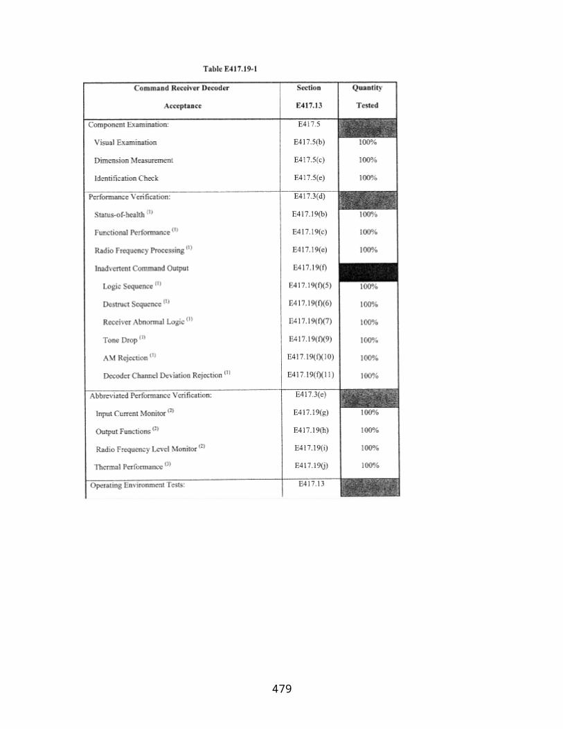
mitigation system is capable of withstanding the release event triggering the scenario and would function as intended.
(5) Additional factors in selecting a worst-case scenario. A launch operator's worst-case release scenario for a toxic propellant must account for each factor that would result in a greater toxic hazard distance, such as a smaller quantity of the toxic propellant than required by paragraph (e)(1) of this section, that is handled at a higher process temperature or pressure.
(f) Worst-case alternative release scenario analysis. A launch operator's worst-case alternative release scenario analysis must account for the following:
(1) The worst-case release scenario for each toxic propellant and for each toxic propellant handling process;
(2) Each release event that is more likely to occur than the worst-case release scenario that is determined in paragraph (e) of this section;
(3) Each release scenario that exceeds a toxic concentration threshold at a distance that reaches the general public;
(4) Each potential transfer hose release due to splits or sudden hose uncoupling;
(5) Each potential process piping release from failures at flanges, joints, welds, valves, valve seals, and drain bleeds;
(6) Each potential process vessel or pump release due to cracks, seal failure, or drain, bleed, or plug failure;
(7) Each vessel overfilling and spill, or over pressurization and venting through relief valves or rupture disks;
(8) Shipping container mishandling and breakage or puncturing leading to a spill;
(9) Mishandling or dropping flight or ground hardware that contains toxic commodities;
(10) Each active and passive mitigation system provided they are capable of withstanding the event that triggered the release and would still be functional;
(11) History of each accident experienced by the launch operator involving the release of a toxic propellant; and
(12) Each failure scenario.
(g) Toxic hazard distances for launch processing. For each process involving a toxic propellant, a launch operator must perform an air dispersion analysis to determine the
479
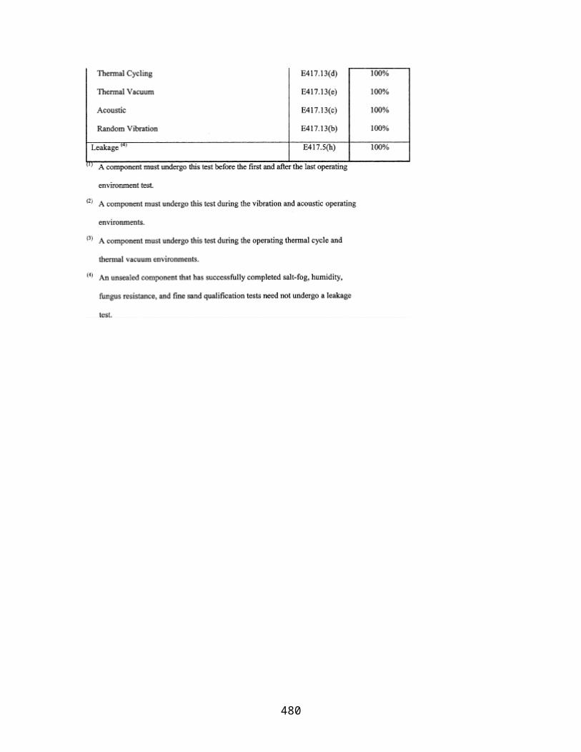
hazard distance for the worst-case release scenario or the worst-case alternative release scenario as determined under paragraphs (e) and (f) of this section. A launch operator must use either the methodology provided in the RMP Offsite Consequence Analysis Guidance, dated April 1999, or an air dispersion modeling technique that is applicable to the proposed launch. A launch operator's air dispersion modeling technique must account for the following analysis parameters:
(1) Toxic concentration thresholds. A launch operator must use the toxic concentration thresholds defined by section I417.3(c).
(2) Wind speed and atmospheric stability class. A launch operator, for the worst-case release analysis, must use a wind speed of 1.5 meters per second and atmospheric stability class F. If the launch operator demonstrates that local meteorological data applicable to the source of a toxic release show a higher wind minimum wind speed or less stable atmosphere during the three previous years, the launch operator may use these minimums. The launch operator, for analysis of the worst-case alternative scenario, must use statistical meteorological conditions for the location of the source.
(3) Ambient temperature and humidity. For a worst-case release scenario analysis of a toxic propellant, the launch operator must use the highest daily maximum temperature from the last three years and average humidity for the site, based on temperature and humidity data gathered at the source location or at a local meteorological station. For analysis of a worst-case alternative release scenario, the launch operator must use typical temperature and humidity data gathered at the source location or at a local meteorological station.
(4) Height of release. The launch operator must analyze the worst-case release of a toxic propellant assuming a ground level release. For a worst-case alternative scenario analysis of a toxic propellant, the release scenario may determine release height.
(5) Surface roughness. The launch operator must use either an urban or rural topography, as appropriate. Urban means that there are many obstacles in the immediate area; obstacles include buildings or trees. Rural means there are no buildings in the immediate area and the terrain is generally flat and unobstructed.
(6) Dense or neutrally buoyant gases. Models or tables used for dispersion analysis of a toxic propellant must account for gas density.
(7) Temperature of release substance. For a worst-case release scenario, the launch operator must account for the release of liquids other than gases liquefied by refrigeration at the highest daily maximum temperature, based on data for the previous three years appropriate to the source of the potential toxic release, or at process temperature, whichever is higher. For a worst-case alternative scenario, the launch operator may consider toxic propellants released at a process or ambient temperature that is appropriate for the scenario.
480

(h) Toxic hazard areas for launch processing . A launch operator, having determined the toxic hazard distance for the toxic concentration threshold for each toxic propellant involved in a process using either a worst-case release scenario or a worst-case alternative release scenario, must determine the toxic hazard area for the process as a circle centered at the potential release point with a radius equal to the greatest toxic hazard distance for the toxic propellants involved in the process. A launch operator does not have to satisfy this section if:
(1) There are no populated areas contained or partially contained within the toxic hazard area; and
(2) There is no member of the public present within the toxic hazard area during the process.
(i) Evacuation of populated areas within a toxic hazard area. For a process where there is a populated area that is contained or partially contained within the toxic hazard area, the launch processing operation does not have to satisfy this section if the launch operator evacuates the public from the populated area and ensures that no member of the public is present within the toxic hazard area during the operation. A launch operator must coordinate notification and evacuation procedures with the Local Emergency Planning Committee (LEPC) and ensure that notification and evacuation occurs according to its launch plans, including the launch operator's ground safety plan, hazard area surveillance and clearance plan, accident investigation plan, and local agreements and public coordination plan.
(j) Meteorological constraints for launch processing. For a launch processing operation with the potential for a toxic release where there is a populated area that is contained or partially contained within the toxic hazard area and that will not be evacuated as required by paragraph (i) of this section, the operation is exempt from further requirements in this section if the launch operator constrains the process to favorable wind conditions or during times when atmospheric conditions result in reduced toxic hazard distances such that the potentially affected populated area is outside the toxic hazard area. A launch operator must employ wind and other meteorological constraints that satisfy the following:
(1) A launch operator must limit a launch processing operation to times during which prevailing winds will transport a toxic release away from populated areas that would otherwise be at risk. If the mean wind speed during the operation is equal to or greater than four knots, the launch operator must re-define the toxic hazard area by reducing the circular toxic hazard area as determined in paragraph (h) of this section to one or more arc segments that do not contain a populated area. Each arc segment toxic hazard area must have the same radius as the circular toxic hazard area and must be defined by a range of downwind bearings. If the mean wind speed during the operation is less than four knots, the toxic hazard area for the operation must be the full 360-degree toxic hazard area as defined by paragraph (h) of this section. The total arc width of an arc segment hazard area for launch processing must be greater than or equal to 30 degrees. If
481
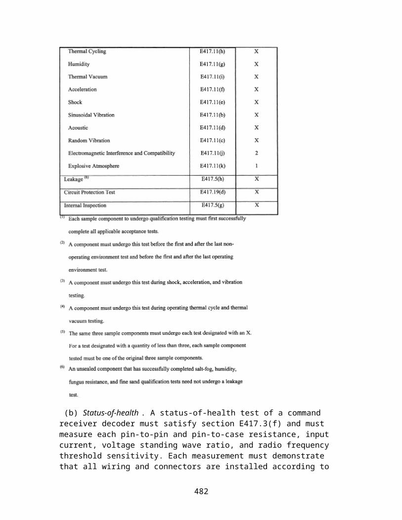
the launch operator determines the standard deviation of the measured wind direction, the total arc width of an arc segment hazard area must include all azimuths within the mean measured wind direction plus three sigma and the mean measured wind direction minus three sigma; otherwise, the following apply for the conditions defined by the Pasquil-Gifford meteorological stability classes:
(i) For stable classes D–F, if the mean wind speed is less than 10 knots, the total arc width of the arc segment toxic hazard area must be no less than 90 degrees;
(ii) For stable classes D–F, if the mean wind speed is greater than or equal to 10 knots, the total arc width of the arc segment toxic hazard area must be no less than 45 degrees;
(iii) For neutral class C, the total arc width of the arc segment toxic hazard area must be no less than 60 degrees;
(iv) For slightly unstable class B, the total arc width of the arc segment toxic hazard area must be no less than 105 degrees; and
(v) For mostly unstable class A, the total arc width of the arc segment toxic hazard area must be no less than 150 degrees.
(2) The launch operator must ensure that there are no populated areas within an arc segment toxic hazard area and that no member of the public is present within an arc segment toxic hazard area during the process as defined by paragraph (i) of this section.
(3) A launch operator must establish wind constraints to ensure that winds present at the time of an operation will transport toxicants into an arc segment toxic hazard area and away from populated areas. For each arc segment toxic hazard area, the wind constraints must consist of a range of downwind bearings that are within the arc segment toxic hazard area and that provide a safety buffer, in both the clockwise and counterclockwise directions, that accounts for uncertainty in the spatial and temporal variations of the transport winds.
(4) A launch operator may reduce the radius of the circular toxic hazard area as determined under paragraph (h) of this section by imposing operational meteorological restrictions on specific parameters that mitigate potential toxic downwind concentrations levels at a potentially affected populated area to levels below the toxic concentration threshold of the toxicant in question. The launch operator must establish meteorological constraints to ensure that the operation will be allowed to occur only if the specific meteorological conditions that would reduce the toxic hazard area exist and will continue to exist throughout the operation, or the operation will be terminated.
(k) Implementation of meteorological constraints. A launch operator must use one or more of the following approaches to determine wind direction or other meteorological conditions in order to establish constraints on a launch processing operation or evacuate the populated area in a potential toxic hazard area:
482

(1) The launch operator must ensure that the wind conditions at the time of the process comply with the wind constraints used to define each arc segment toxic hazard area. The launch operator must monitor the vertical profile of winds at the potential toxic release site from ground level to an altitude of 10 meters or the maximum height above ground of the potential release, whichever is larger. The launch operator may proceed with a launch processing operation only if wind vectors meet the wind constraints used to define each arc segment toxic hazard area.
(2) A launch operator must monitor the specific meteorological parameters that affect toxic downwind concentrations at a potential toxic release site for a process and for the sphere of influence out to each populated area within the potential toxic hazard area as defined by paragraph (h) of this section. The launch operator must monitor spatial variations in the wind field that could affect the transport of toxic material between the potential release site and populated areas. The launch operator must acquire real-time meteorological data from sites between the potential release site and each populated area sufficient to demonstrate that the toxic hazard area, when adjusted to the spatial wind field variations, excludes populated areas. Meteorological parameters that affect toxic downwind concentrations from the potential release site and covering the sphere of influence out to the populated areas must fall within the conditions as determined in paragraph (j)(4) of this section. A launch operator must use one of the following methods to determine the meteorological conditions that will constrain a launch processing operation:
(i) A launch operator may employ real-time air dispersion models to determine the toxic hazard distance for the toxic concentration threshold and proximity of a toxicant to populated areas. A launch operator, when employing this method, must proceed with a launch processing operation only if real-time modeling of the potential release demonstrates that the toxic hazard distance would not reach populated areas. The launch operator's process for carrying out this method must include the use of an air dispersion modeling technique that complies with paragraph (g) of this section and providing real-time meteorological data for the sphere of influence around a potential toxic release site as input to the air dispersion model. The launch operator's process must also include a review of the meteorological conditions to identify changing conditions that could affect the toxic hazard distance for a toxic concentration threshold prior to proceeding with the operation.
(ii) A launch operator may use air dispersion modeling techniques to define the meteorological conditions that, when present, would prevent a toxic hazard distance for a toxic concentration threshold from reaching populated areas. The launch operator, when employing this method, must constrain the associated launch processing operation to be conducted only when the prescribed meteorological conditions exist. A launch operator's air dispersion modeling technique must comply with paragraph (g) of this section.
(l) Statistical toxic risk management for launch processing. The launch operator must use statistical toxic risk management to protect public safety if a process that involves the use of a toxic propellant does not satisfy the containment requirements of paragraph (d) of
483

this section. A launch operator, for each such case, must perform a toxic risk assessment and develop criteria that protect the public from risks due to planned and potential toxic release. A launch operator must ensure that the resultant toxic risk meets the collective and individual risk criteria requirements defined in §417.107(b). A launch operator's toxic risk assessment must account for the following:
(1) All credible equipment failure and non-failure modes, along with the consequent release and combustion of toxic propellants;
(2) Equipment failure rates;
(3) The effect of positive or negative buoyancy on the rise or descent of the released toxic propellants;
(4) The influence of atmospheric physics on the transport and diffusion of toxic propellants released;
(5) Meteorological conditions at the time of the process;
(6) Population density, location, susceptibility (health categories) and sheltering for populations within each potential toxic hazard area; and
(7) Exposure duration and toxic propellant concentration or dosage that would result in casualty for populations.
(m) Launch processing toxic release hazard analysis products. The products of a launch operator's toxic release hazards analysis for launch processing must include the following:
(1) For each worst-case release scenario, a description of the vessel or pipeline and toxic propellant selected as the worst case for each process, assumptions and parameters used, and the rationale for selection of that scenario. Assumptions must include use of administrative controls and passive mitigation that were assumed to limit the quantity that could be released. The description must include the anticipated effect of the controls and mitigation on the release quantity and rate;
(2) For each worst-case alternative release scenario, a description of the scenario identified for each process, assumptions and parameters used, and the rationale for the selection of that scenario. Assumptions must include use of administrative controls and passive mitigation that were assumed to limit the quantity that could be released. The description must include the anticipated effect of the controls and mitigation on the release quantity and rate;
(3) Estimated quantity released, release rate, and duration of release for each worst-case scenario and worst-case alternative scenario for each process;
484
(4) A description of the methodology used to determine the toxic hazard distance for each toxic concentration threshold;
(5) Data used to estimate off-site population receptors potentially affected; and
(6) The following data for each worst-case scenario and worst-case alternative release scenario:
(i) Chemical name;
(ii) Physical state;
(iii) Basis of results (provide model name if used, or other methodology);
(iv) Scenario (explosion, fire, toxic gas release, or liquid spill and vaporization);
(v) Quantity released in pounds;
(vi) Release rate;
(vii) Release duration;
(viii) Wind speed and atmospheric stability class;
(ix) Topography;
(x) Toxic hazard distance;
(xi) All members of the public within the toxic hazard distance;
(xii) Any passive mitigation considered; and
(xiii) Active mitigation considered (worst-case alternative release scenario only).
485
Appendix J to Part 417—Ground Safety Analysis Report
J417.1 General
(a) This appendix provides the content and format requirements for a ground safety analysis report. A launch operator must perform a ground safety analysis as required by subpart E of part 417 and document the analysis in a ground safety analysis report that satisfies this appendix, as required by §417.402(d).
(b) A ground safety analysis report must contain hazard analyses that describe each hazard control, and describe a launch operator's hardware, software, and operations so that the FAA can assess the adequacy of the hazard analysis. A launch operator must document each hazard analysis on hazard analysis forms as required by §J417.3(d) and file each system and operation descriptions as a separate volume of the report.
(c) A ground safety analysis report must include a table of contents and provide definitions of any acronyms and unique terms used in the report.
(d) A launch operator's ground safety analysis report may reference other documents filed with the FAA that contain the information required by this appendix.
J417.3 Ground safety analysis report chapters
(a) Introduction . A ground safety analysis report must include an introductory chapter that describes all administrative matters, such as purpose, scope, safety certification of personnel who performed any part of the analysis, and each special interest issue, such as a high-risk situation or potential non-compliance with any applicable FAA requirement.
(b) Launch vehicle and operations summary. A ground safety analysis report must include a chapter that provides general safety information about the vehicle and operations, including the payload and flight termination system. This chapter must serve as an executive summary of detailed information contained within the report.
(c) Systems, subsystems, and operations information. A ground safety analysis report must include a chapter that provides detailed safety information about each launch vehicle system, subsystem and operation and each associated interface. The data in this chapter must include the following:
(1) Introduction. A launch operator's ground safety analysis report must contain an introduction to its systems, subsystems, and operations information that serves as a roadmap and checklist to ensure all applicable items are covered. All flight and ground hardware must be identified with a reference to where the items are discussed in the document. All interfacing hardware and operations must be identified with a reference to where the items are discussed in the document. The introduction must identify interfaces between systems and operations and the boundaries that describe a system or operation.
486

(2) Subsystem description. For each hardware system identified in a ground safety analysis report as falling under one of the hazardous systems listed in paragraphs (c)(3), (c)(4) and (c)(5) of this section, the report must identify each of the hardware system's subsystems. A ground safety analysis report must describe each hazardous subsystem using the following format:
(i) General description including nomenclature, function, and a pictorial overview;
(ii) Technical operating description including text and figures describing how a subsystem works and any safety features and fault tolerance levels;
(iii) Each safety critical parameter, including those that demonstrate established system safety approaches that are not evident in the technical operating description or figures, such as factors of safety for structures and pressure vessels;
(iv) Each major component, including any part of a subsystem that must be technically described in order to understand the subsystem hazards. For a complex subsystem such as a propulsion subsystem, the ground safety analysis report must provide a majority of the detail of the subsystem including any figures at the major component level such as tanks, engines and vents. The presentation of figures in the report must progress in detail from broad overviews to narrowly focused figures. Each figure must have supporting text that explains what the figure is intended to illustrate;
(v) Ground operations and interfaces including interfaces with other launch vehicle and launch site subsystems. A ground safety analysis report must identify a launch operator's and launch site operator's hazard controls for all operations that are potentially hazardous to the public. The report must contain facility figures that illustrate where hazardous operations take place and must identify all areas where controlled access is employed as a hazard control; and
(vi) Hazard analysis summary of subsystem hazards that identifies each specific hazard and the threat to public safety. This summary must provide cross-references to the hazard analysis form required by paragraph (d) of this section and indicate the nature of the control, such as design margin, fault tolerance, or procedure.
(3) Flight hardware. For each stage of a launch vehicle, a ground safety analysis report must identify all flight hardware systems, using the following sectional format:
(i) Structural and mechanical systems;
(ii) Ordnance systems;
(iii) Propulsion and pressure systems;
(iv) Electrical and non-ionizing radiation systems; and
487
(v) Ionizing radiation sources and systems.
(4) Ground hardware. A ground safety analysis report must identify the launch operator's and launch site operator's ground hardware, including launch site and ground support equipment, that contains hazardous energy or materials, or that can affect flight hardware that contains hazardous energy or materials. A launch operator must identify all ground hardware by using the following sectional format:
(i) Structural and mechanical ground support and checkout systems;
(ii) Ordnance ground support and checkout systems;
(iii) Propulsion and pressure ground support and checkout systems;
(iv) Electrical and non-ionizing radiation ground support and checkout systems;
(v) Ionizing radiation ground support and checkout systems;
(vi) Hazardous materials; and
(vii) Support and checkout systems and any other safety equipment used to monitor or control a potential hazard not otherwise addressed above.
(5) Flight safety system. A ground safety analysis report must describe each hazard of inadvertent actuation of the launch operator's flight safety system, potential damage to the flight safety system during ground operations, and each hazard control that the launch operator will implement.
(6) Hazardous materials. A ground safety analysis report must:
(i) Identify each hazardous material used in all the launch operator's flight and ground systems, including the quantity and location of each material;
(ii) Contain a summary of the launch operator's approach for protecting the public from toxic plumes, including the toxic concentration thresholds used to control public exposure and a description of any related local agreements;
(iii) Describe any toxic plume model used to protect public safety and contain any algorithms used by the model; and
(iv) Include the products of the launch operator's toxic release hazard analysis for launch processing as defined by section I417.7(m) of appendix I of this part for each launch that involves the use of any toxic propellants.
(d) Hazard analysis. A ground safety analysis report must include a chapter containing a hazard analysis of the launch vehicle and launch vehicle processing and interfaces. The
488

hazard analysis must identify each hazard and all hazard controls that the launch operator will implement. A ground safety analysis report must contain the results of the launch operator's hazard analysis of each system, subsystem, and operation using a standardized format that includes the items listed on the example hazard analysis form provided in figure J417–1 and that satisfies the following:
(1) Introduction. A ground safety analysis report must contain an introduction that serves as a roadmap and checklist to the launch operator's hazard analysis forms. A launch operator must identify all flight hardware, ground hardware, interfacing hardware, and operations with a reference to where the items are discussed in the ground safety analysis report. The introduction must explain how a launch operator presents its hazard analysis in terms of hazard identification numbers as identified in figure J417–1.
(2) Analysis. A launch operator may present each hazard on a separate form or consolidate hazards of a specific system, subsystem, component, or operation onto a single form. There must be at least one form for each hazardous subsystem and each hazardous subsystem operation. A launch operator must state which approach it has chosen in the introduction to the hazard analysis section. A launch operator must track each identified hazard control separately.
(3) Numbering. A launch operator must number each hazard analysis form with the applicable system or subsystem identified. A launch operator must number each line item on a hazard analysis form with numbers and letters provided for multiple entries against an individual line item. A line item consists of a hardware or operation description and a hazard.
(4) Hazard analysis data. A hazard analysis form must contain or reference all information necessary to understand the relationship of a system, subsystem, component, or operation with a hazard cause, control, and verification.
(e) Hazard analysis supporting data. A ground safety analysis report must include data that supports the hazard analysis. If such data does not fit onto the hazard analysis form, a launch operator must provide the data in a supporting data chapter. This chapter must contain a table of contents and may reference other documents that contain supporting data.
489

PART 420—LICENSE TO OPERATE A LAUNCH SITE
Section Contents
Subpart A—General
§ 420.1 Scope. § 420.3 Applicability. § 420.5 Definitions. §§ 420.6-420.14 [Reserved]
Subpart B—Criteria and Information Requirements for Obtaining a License
§ 420.15 Information requirements. § 420.17 Bases for issuance of a license. § 420.19 Launch site location review—general. § 420.21 Launch site location review—launch site boundary. § 420.23 Launch site location review—flight corridor. § 420.25 Launch site location review—risk analysis. § 420.27 Launch site location review—information requirements. § 420.29 Launch site location review for unproven launch vehicles. § 420.30 Launch site location review for permitted launch vehicles. § 420.31 Agreements. §§ 420.32-420.40 [Reserved]
Subpart C—License Terms and Conditions
§ 420.41 License to operate a launch site—general. § 420.43 Duration. § 420.45 Transfer of a license to operate a launch site. § 420.47 License modification. § 420.49 Compliance monitoring.
Subpart D—Responsibilities of a Licensee
§ 420.51 Responsibilities—general. § 420.53 Control of public access. § 420.55 Scheduling of launch site operations. § 420.57 Notifications. § 420.59 Launch site accident investigation plan. § 420.61 Records. § 420.63 Explosive siting. § 420.65 Handling of solid propellants. § 420.67 Storage or handling of liquid propellants. § 420.69 Solid and liquid propellants located together. § 420.71 Lightning protection. Appendix A to Part 420—Method for Defining a Flight CorridorAppendix B to Part 420—Method for Defining a Flight CorridorAppendix C to Part 420—Risk AnalysisAppendix D to Part 420—Impact Dispersion Areas and Casualty Expectancy Estimate for an Unguided Suborbital Launch Vehicle
490
Appendix E to Part 420—Tables for Explosive Site Plan
Authority: 49 U.S.C. 70101–70121.
Source: Docket No. FAA–1999–5833, 65 FR 62861, Oct. 19, 2000, unless otherwise noted.
Subpart A—General
§ 420.1 Scope.
This part prescribes the information and demonstrations that must be provided to the FAA as part of a license application, the bases for license approval, license terms and conditions, and post-licensing requirements with which a licensee shall comply to remain licensed. Requirements for preparing a license application are contained in part 413 of this subchapter.
§ 420.3 Applicability.
This part applies to any person seeking a license to operate a launch site or to a person licensed under this part. A person operating a site that only supports amateur rocket activities as defined in 14 CFR 1.1, does not need a license under this part to operate the site.
[Docket No. FAA–2007–27390, 73 FR 73782, Dec. 4, 2008]
§ 420.5 Definitions.
For the purpose of this part.
Ballistic coefficient means the weight of an object divided by the quantity product of the coefficient of drag of the object and the area of the object.
Compatibility means the chemical property of materials that may be located together without increasing the probability of an accident or, for a given quantity, the magnitude of the effects of such an accident.
Debris dispersion radius (Dmax) means the estimated maximum distance from a launch point that debris travels given a worst-case launch vehicle failure and flight termination early in flight. For an expendable launch vehicle, flight termination is assumed to occur at 10 seconds into flight.
Downrange area means a portion of a flight corridor beginning where a launch area ends and ending 5,000 nautical miles from the launch point, or where the IIP leaves the surface
491
of the Earth, whichever is shorter, for an orbital launch vehicle; and ending with an impact dispersion area for a guided sub-orbital launch vehicle.
E,F,G coordinate system means an orthogonal, Earth-fixed, geocentric, right-handed system. The origin of the coordinate system is at the center of an ellipsoidal Earth model. The E-axis is positive directed through the Greenwich meridian. The F-axis is positive directed though 90 degrees east longitude. The EF-plane is coincident with the ellipsoidal Earth model's equatorial plane. The G-axis is normal to the EF-plane and positive directed through the north pole.
E,N,U coordinate system means an orthogonal, Earth-fixed, topocentric, right-handed system. The origin of the coordinate system is at a launch point. The E-axis is positive directed east. The N-axis is positive directed north. The EN-plane is tangent to an ellipsoidal Earth model's surface at the origin and perpendicular to the geodetic vertical. The U-axis is normal to the EN-plane and positive directed away from the Earth.
Effective casualty area (A c ) means the aggregate casualty area of each piece of debris created by a launch vehicle failure at a particular point on its trajectory. The effective casualty area for each piece of debris is the area within which 100 percent of the unprotected population on the ground are assumed to be a casualty, and outside of which 100 percent of the population are assumed not to be a casualty. An effective casualty area accounts for the characteristics of the debris piece, including its size, the path angle of its trajectory, impact explosions, and debris skip, splatter, and bounce. An effective casualty area also accounts for the size of a person.
Explosive means any chemical compound or mechanical mixture that, when subjected to heat, impact, friction, detonation or other suitable initiation, undergoes a rapid chemical change that releases large volumes of highly heated gases that exert pressure in the surrounding medium. The term applies to materials that either detonate or deflagrate.
xplosive division means the division within hazard class 1 of an explosive as defined in the United Nations Organization classification system for transport of dangerous goods, and as determined in accordance with 49 CFR part 173, subpart C.
Explosive equivalent means a measure of the blast effects from explosion of a given quantity of material expressed in terms of the weight of trinitrotoluene (TNT) that would produce the same blast effects when detonated.
Explosive hazard facility means a facility at a launch site where solid propellant, liquid propellant, or other explosives are stored or handled.
Flight azimuth means the initial direction in which a launch vehicle flies relative to true north expressed in degrees-decimal-degrees.
492

Flight corridor means an area on the Earth's surface estimated to contain the hazardous debris from nominal flight of a launch vehicle, and non-nominal flight of a launch vehicle assuming a perfectly functioning flight termination system or other flight safety system.
Guided suborbital launch vehicle means a suborbital rocket that employs an active guidance system.
Hazard class means the class of an explosive as defined by the United Nations Organization classification system for transport of dangerous goods, and as determined in accordance with 49 CFR part 173, subpart C.
Impact dispersion area means an area representing an estimated three standard deviation dispersion about a nominal impact point of an intermediate or final stage of a suborbital launch vehicle.
Impact dispersion factor means a constant used to estimate, using a stage apogee, a three standard deviation dispersion about a nominal impact point of an intermediate or final stage of a suborbital launch vehicle.
Impact dispersion radius (R i ) means a radius that defines an impact dispersion area.
Impact range means the distance between a launch point and the impact point of a suborbital launch vehicle stage.
Impact range factor means a constant used to estimate, when multiplied by a stage apogee, the nominal impact point of an intermediate or final stage of a suborbital launch vehicle.
Instantaneous impact point (IIP) means an impact point, following thrust termination of a launch vehicle. IIP may be calculated with or without atmospheric drag effects.
Instantaneous impact point (IIP) range rate means a launch vehicle's estimated IIP velocity along the Earth's surface.
Intraline distance means the minimum distance permitted between any two explosive hazard facilities in the ownership, possession or control of one launch site customer.
Launch area means, for a flight corridor defined in accordance with appendix A of this part, the portion of a flight corridor from the launch point to a point 100 nautical miles in the direction of the flight azimuth. For a flight corridor defined in accordance with appendix B of this part, a launch area is the portion of a flight corridor from the launch point to the enveloping line enclosing the outer boundary of the last debris dispersion circle.
Launch point means a point on the Earth from which the flight of a launch vehicle begins, and is defined by its geodetic latitude, longitude and height on an ellipsoidal Earth model.
493
Launch site accident means an unplanned event occurring during a ground activity at a launch site resulting in a fatality or serious injury (as defined in 49 CFR 830.2) to any person who is not associated with the activity, or any damage estimated to exceed $25,000 to property not associated with the activity.
Net explosive weight (NEW) means the total weight, expressed in pounds, of explosive material or explosive equivalency contained in an item.
Nominal means, in reference to launch vehicle performance, trajectory, or stage impact point, a launch vehicle flight where all launch vehicle aerodynamic parameters are as expected, all vehicle internal and external systems perform as planned, and there are no external perturbing influences (e.g., winds) other than atmospheric drag and gravity.
Overflight dwell time means the period of time it takes for a launch vehicle's IIP to move past a populated area. For a given populated area, the overflight dwell time is the time period measured along the nominal trajectory IIP ground trace from the time point whose normal with the trajectory intersects the most uprange part of the populated area to the time point whose normal with the trajectory intersects the most downrange part of the populated area.
Overflight exclusion zone means a portion of a flight corridor which must remain clear of the public during the flight of a launch vehicle.
Populated area means a land area with population.
Population density means the number of people per unit area in a populated area.
Position data means data referring to the current position of a launch vehicle with respect to flight time expressed through the X, Y, Z coordinate system.
Public means people and property that are not involved in supporting a licensed or permitted launch, and includes those people and property that may be located within the boundary of a launch site, such as visitors, any individual providing goods or services not related to launch processing or flight, and any other launch operator and its personnel.
Public area means any area outside a hazard area and is an area that is not in the possession, ownership or other control of a launch site operator or of a launch site customer who possesses, owns or otherwise controls that hazard area.
Public area distance means the minimum distance permitted between a public area and an explosive hazard facility.
Public traffic route distance means the minimum distance permitted between a public highway or railroad line and an explosive hazard facility.
494

Trajectory means the position and velocity components as a function of time of a launch vehicle relative to an x, y, z coordinate system, expressed in x, y, z, x, y, z.
Unguided sub-orbital launch vehicle means a sub-orbital rocket that does not have a guidance system.
X, Y, Z coordinate system means an orthogonal, Earth-fixed, topocentric, right-handed system. The origin of the coordinate system is at a launch point. The x-axis coincides with the initial launch azimuth and is positive in the downrange direction. The y-axis is positive to the left looking downrange. The xy-plane is tangent to the ellipsoidal earth model's surface at the origin and perpendicular to the geodetic vertical. The z-axis is normal to the xy-plane and positive directed away from the earth.
φ 0, λ 0, h 0means a latitude, longitude, height system where φ0is the geodetic latitude of a launch point, λ0is the east longitude of the launch point, and h0is the height of the launch point above the reference ellipsoid. φ0and λ0are expressed in degrees-decimal-degrees.
[Docket No. FAA–1999–5833, 65 FR 62861, Oct. 19, 2000, as amended by Amdt. 420–3, 72 FR 17019, Apr. 6, 2007]
§§ 420.6-420.14 [Reserved]
Subpart B—Criteria and Information Requirements for Obtaining a License
§ 420.15 Information requirements.
(a) General —(1) Launch site operator. An applicant shall identify the name and address of the applicant, and the name, address, and telephone number of any person to whom inquiries and correspondence should be directed.
(2) Launch site. An applicant shall provide the name and location of the proposed launch site and include the following information:
(i) A list of downrange equipment;
(ii) A description of the layout of the launch site, including launch points;
(iii) The types of launch vehicles to be supported at each launch point;
(iv) The range of launch azimuths planned from each launch point; and
(v) The scheduled operational date.
(3) Foreign ownership. Identify foreign ownership of the applicant, as follows:
495

(i) For a sole proprietorship or partnership, all foreign owners or partners;
(ii) For a corporation, any foreign ownership interest of 10 percent or more; and
(iii) For a joint venture, association, or other entity, any foreign entities participating in the entity.
(b) Environmental. An applicant shall provide the FAA with information for the FAA to analyze the environmental impacts associated with the operation of the proposed launch site. The information provided by an applicant must be sufficient to enable the FAA to comply with the requirements of the National Environment Policy Act, 42 U.S.C. 4321 et seq. (NEPA), the Council on Environmental Quality Regulations for Implementing the Procedural Provisions of NEPA, 40 CFR parts 1500–1508, and the FAA's Procedures for Considering Environmental Impacts, FAA Order 1050.1D. An applicant shall submit environmental information concerning a proposed launch site not covered by existing environmental documentation, and other factors as determined by the FAA.
(c) Launch site location. (1) Except as provided by paragraph (c)(2) of this section, an applicant shall provide the information necessary to demonstrate compliance with §§420.19–420.29.
(2) An applicant who is proposing to locate a launch site at an existing launch point at a federal launch range is not required to comply with paragraph (c)(1) of this section if a launch vehicle of the same type and class as proposed for the launch point has been safely launched from the launch point.
(d) Explosive site plan. (1) Except as provided by paragraph (d)(2) of this section, an applicant shall submit an explosive site plan that complies with §§420.63, 420.65, 420.67, and 420.69.
(2) If an applicant plans to operate a launch site located on a federal launch range, and if the applicant is required by the federal launch range to comply with the federal launch range's explosive safety requirements, the applicant shall submit the explosive site plan submitted to the federal launch range.
(e) Launch site operations. An applicant shall provide the information necessary to demonstrate compliance with the requirements of §§420.53, 420.55, 420.57, 420.59, 420.61, and 420.71.
§ 420.17 Bases for issuance of a license.
(a) The FAA will issue a license under this part when the FAA determines that:
(1) The application provides the information required by §420.15;
496
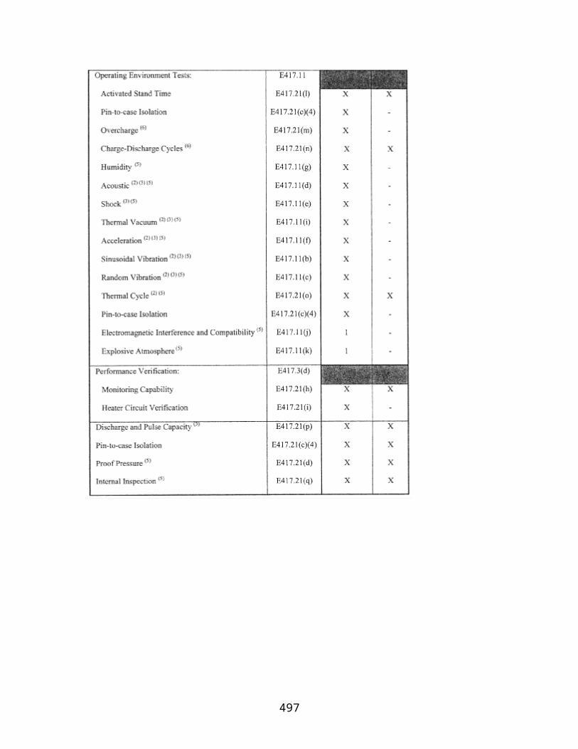
(2) The FAA has completed an analysis of the environmental impacts associated with the proposed operation of the launch site, in accordance with NEPA, 40 CFR parts 1500–1508, and FAA Order 1050.1D;
(3) The launch site location meets the requirements of §§420.19, 420.21, 420.23, 420.25, 420.27, and 420.29;
(4) The applicant has completed the agreements required by §420.31;
(5) The application demonstrates that the applicant shall satisfy the requirements of §§420.53, 420.55, 420.57, 420.59, 420.61 and 420.71;
(6) The explosive site plan meets the criteria of §§420.63, 420.65, 420.67 and 420.69; and
(7) Issuing a license would not jeopardize foreign policy or national security interests of the United States.
(b) The FAA advises an applicant, in writing, of any issue arising during an application review that would lead to denial. The applicant may respond in writing, submit additional information, or amend its license application.
§ 420.19 Launch site location review—general.
(a) To gain approval for a launch site location, an applicant shall demonstrate that for each launch point proposed for the launch site, at least one type of expendable or reusable launch vehicle can be flown from the launch point safely. For purposes of the launch site location review:
(1) A safe launch must possess a risk level estimated, in accordance with the requirements of this part, not to exceed an expected average number of 0.00003 casualties (Ec) to the collective member of the public exposed to hazards from the flight (Ec≤ 30 × 10−6).
(2) Types of launch vehicles include orbital expendable launch vehicles, guided sub-orbital expendable launch vehicles, unguided sub-orbital expendable launch vehicles, and reusable launch vehicles. Orbital expendable launch vehicles are further classified by weight class, based on the weight of payload the launch vehicle can place in a 100-nm orbit, as defined in table 1.
(b) If an applicant proposes to have more than one type of launch vehicle flown from a launch point, the applicant shall demonstrate that each type of expendable or reusable launch vehicle planned to be flown from the launch point can be flown from the launch point safely.
497

(c) If an applicant proposes to have more than one weight class of orbital expendable launch vehicles flown from a launch point, the applicant shall demonstrate that the heaviest weight class planned to be flown from the launch point can be flown from the launch point safely.
Table 1 of §420.19—Orbital Expendable Launch Vehicle Classes by Payload Weight (lbs)
100 nm orbit
Weight class
Small Medium Medium large Large
28 degrees inclination* ≤4400 >4400 to ≤11100 >11100 to ≤18500 >18500
90 degrees inclination ≤3300 >3300 to ≤8400 >8400 to ≤15000 >15000
*28 degrees inclination orbit from a launch point at 28 degrees latitude.
§ 420.21 Launch site location review—launch site boundary.
(a) The distance from any proposed launch point to the closest launch site boundary must be at least as great as the debris dispersion radius of the largest launch vehicle type and weight class proposed for the launch point.
(b) For a launch site supporting any expendable launch vehicle, an applicant shall use the largest distance provided by table 2 for the type and weight class of any launch vehicle proposed for the launch point.
(c) For a launch site supporting any reusable launch vehicle, an applicant shall determine the debris dispersion radius that represents the maximum distance from a launch point that debris travels given a worst-case launch vehicle failure in the launch area. An applicant must clearly and convincingly demonstrate the validity of its proposed debris dispersion radius.
Table 2 of §420.21—Minimum Distance From Launch Point to Launch Site Boundary (feet)
Orbital expendable launch vehicle class Type of suborbital launch vehicle
Small Medium Medium large Large Guided Unguided
7300 9300 10600 13000 8000 1600
§ 420.23 Launch site location review—flight corridor.
(a) Guided orbital expendable launch vehicle. For a guided orbital expendable launch vehicle, an applicant shall define a flight corridor that:
498

(1) Encompasses an area that the applicant estimates, in accordance with the requirements of this part, to contain debris with a ballistic coefficient of ≥ 3 pounds per square foot, from any non-nominal flight of a guided orbital expendable launch vehicle from the launch point to a point 5000 nm downrange, or where the IIP leaves the surface of the Earth, whichever is shorter;
(2) Includes an overflight exclusion zone where the public risk criteria of 30×10−6would be exceeded if one person were present in the open; and
(3) Uses one of the methodologies provided in appendix A or B of this part. The FAA will approve an alternate method if an applicant provides a clear and convincing demonstration that its proposed method provides an equivalent level of safety to that required by appendix A or B of this part.
(b) Guided sub-orbital expendable launch vehicle. For a guided sub-orbital expendable launch vehicle, an applicant shall define a flight corridor that:
(1) Encompasses an area that the applicant estimates, in accordance with the requirements of this part, to contain debris with a ballistic coefficient of ≥ 3 pounds per square foot, from any non-nominal flight of a guided sub-orbital expendable launch vehicle from the launch point to impact with the earth's surface;
(2) Includes an impact dispersion area for the launch vehicle's last stage;
(3) Includes an overflight exclusion zone where the public risk criteria of 30×10−6would be exceeded if one person were present in the open; and
(4) Uses one of the methodologies provided in appendices A or B to this part. The FAA will approve an alternate method if an applicant provides a clear and convincing demonstration that its proposed method provides an equivalent level of safety to that required by appendix A or B of this part.
(c) Unguided sub-orbital expendable launch vehicle. (1) For an unguided sub-orbital expendable launch vehicle, an applicant shall define the following using the methodology provided by appendix D of this part:
(i) Impact dispersion areas that the applicant estimates, in accordance with the requirements of this part, to contain the impact of launch vehicle stages from nominal flight of an unguided sub-orbital expendable launch vehicle from the launch point to impact with the earth's surface; and
(ii) An overflight exclusion zone where the public risk criteria of 30×10−6would be exceeded if one person were present in the open.
499

(2) The FAA will approve an alternate method if an applicant provides a clear and convincing demonstration that its proposed method provides an equivalent level of safety to that required by appendix D of this part.
(3) An applicant shall base its analysis on an unguided suborbital launch vehicle whose final launch vehicle stage apogee represents the intended use of the launch point.
(d) Reusable launch vehicle. For a reusable launch vehicle, an applicant shall define a flight corridor that contains the hazardous debris from nominal and non-nominal flight of a reusable launch vehicle. The applicant must provide a clear and convincing demonstration of the validity of its flight corridor.
§ 420.25 Launch site location review—risk analysis.
(a) If a flight corridor or impact dispersion area defined by section 420.23 contains a populated area, the applicant shall estimate the casualty expectation associated with the flight corridor or impact dispersion area. An applicant shall use the methodology provided in appendix C to this part for guided orbital or suborbital expendable launch vehicles and appendix D for unguided suborbital launch vehicles. The FAA will approve an alternate method if an applicant provides a clear and convincing demonstration that its proposed method provides an equivalent level of safety to that required by appendix C or D of this part. For a reusable launch vehicle, an applicant must provide a clear and convincing demonstration of the validity of its risk analysis.
(b) For licensed launches, the FAA will not approve the location of the proposed launch point if the estimated expected casualty exceeds 30× 10−6.
[Docket No. FAA–1999–5833, 65 FR 62861, Oct. 19, 2000, as amended by Amdt. 420–3, 72 FR 17019, Apr. 6, 2007]
§ 420.27 Launch site location review—information requirements.
An applicant shall provide the following launch site location review information in its application:
(a) A map or maps showing the location of each launch point proposed, and the flight azimuth, IIP, flight corridor, and each impact range and impact dispersion area for each launch point;
(b) Each launch vehicle type and any launch vehicle class proposed for each launch point;
(c) Trajectory data;
(d) Wind data, including each month and any percent wind data used in the analysis;
(e) Any launch vehicle apogee used in the analysis;
500

(f) Each populated area located within a flight corridor or impact dispersion area;
(g) The estimated casualty expectancy calculated for each populated area within a flight corridor or impact dispersion area;
(h) The effective casualty areas used in the analysis;
(i) The estimated casualty expectancy for each flight corridor or set of impact dispersion areas; and
(j) If populated areas are located within an overflight exclusion zone, a demonstration that there are times when the public is not present or that the applicant has an agreement in place to evacuate the public from the overflight exclusion zone during a launch.
§ 420.29 Launch site location review for unproven launch vehicles.
An applicant for a license to operate a launch site for an unproven launch vehicle shall provide a clear and convincing demonstration that its proposed launch site location provides an equivalent level of safety to that required by this part.
§ 420.30 Launch site location review for permitted launch vehicles.
If an applicant plans to use its proposed launch site solely for launches conducted under an experimental permit, the FAA will approve a launch site location if the FAA has approved an operating area under part 437 for launches from that site.
[Doc. No. FAA–2006–24197, 72 FR 17019, Apr. 6, 2007]
§ 420.31 Agreements.
(a) Except as provided by paragraph (c) of this section, an applicant shall complete an agreement with the local U.S. Coast Guard district to establish procedures for the issuance of a Notice to Mariners prior to a launch and other such measures as the Coast Guard deems necessary to protect public health and safety.
(b) Except as provided by paragraph (c) of this section, an applicant shall complete an agreement with the FAA Air Traffic Control (ATC) office having jurisdiction over the airspace through which launches will take place, to establish procedures for the issuance of a Notice to Airmen prior to a launch and for closing of air routes during the launch window and other such measures as the FAA ATC office deems necessary to protect public health and safety.
(c) An applicant that plans to operate a launch site located on a federal launch range does not have to comply with section 420.31 if the applicant is using existing federal launch range agreements with the U.S. Coast Guard and the FAA ATC office having jurisdiction over the airspace through which launches will take place.
501

§§ 420.32-420.40 [Reserved]
Subpart C—License Terms and Conditions
§ 420.41 License to operate a launch site—general.
(a) A license to operate a launch site authorizes a licensee to operate a launch site in accordance with the representations contained in the licensee's application, with terms and conditions contained in any license order accompanying the license, and subject to the licensee's compliance with 49 U.S.C. subtitle IX, ch. 701 and this chapter.
(b) A license to operate a launch site authorizes a licensee to offer its launch site to a launch operator for each launch point for the type and any weight class of launch vehicle identified in the license application and upon which the licensing determination is based.
(c) Issuance of a license to operate a launch site does not relieve a licensee of its obligation to comply with any other laws or regulations; nor does it confer any proprietary, property, or exclusive right in the use of airspace or outer space.
§ 420.43 Duration.
A license to operate a launch site remains in effect for five years from the date of issuance unless surrendered, suspended, or revoked before the expiration of the term and is renewable upon application by the licensee.
§ 420.45 Transfer of a license to operate a launch site.
(a) Only the FAA may transfer a license to operate a launch site.
(b) The FAA will transfer a license to an applicant who has submitted an application in accordance with 14 CFR part 413, satisfied the requirements of §420.15, and obtained each approval required by §420.17 for a license.
(c) The FAA may incorporate by reference any findings made part of the record that supported a prior related licensing determination.
§ 420.47 License modification.
(a) Upon application or upon its own initiative, the FAA may modify a license to operate a launch site at any time by issuing a license order that adds, removes, or modifies a license term or condition to ensure compliance with the Act and the requirements of this chapter.
(b) After a license to operate a launch site has been issued, a licensee shall apply to the FAA for modification of its license if:
502
(1) The licensee proposes to operate the launch site in a manner that is not authorized by the license; or
(2) The licensee proposes to operate the launch site in a manner that would make any representation contained in the license application that is material to public health and safety or safety of property no longer accurate and complete.
(c) An application to modify a license shall be prepared and submitted in accordance with part 413 of this chapter. The licensee shall indicate any part of its license or license application that would be changed or affected by a proposed modification.
(d) The FAA approves a modification request that satisfies the requirements of this part.
(e) Upon approval of a license modification, the FAA issues either a written approval to the licensee or a license order modifying the license if a stated term or condition of the license is changed, added, or deleted. A written approval has the full force and effect of a license order and is part of the licensing record.
§ 420.49 Compliance monitoring.
A licensee shall allow access by and cooperate with federal officers or employees or other individuals authorized by the FAA to observe any activities of the licensee, its customers, its contractors, or subcontractors, associated with licensed operation of the licensee's launch site.
Subpart D—Responsibilities of a Licensee
§ 420.51 Responsibilities—general.
(a) A licensee shall operate its launch site in accordance with the representations in the application upon which the licensing determination is based.
(b) A licensee is responsible for compliance with 49 U.S.C. Subtitle IX, ch. 701 and for meeting the requirements of this chapter.
§ 420.53 Control of public access.
(a) A licensee shall prevent unauthorized access to the launch site, and unauthorized, unescorted access to explosive hazard facilities or other hazard areas not otherwise controlled by a launch operator, through the use of security personnel, surveillance systems, physical barriers, or other means approved as part of the licensing process.
(b) A licensee shall notify anyone entering the launch site of safety rules and emergency and evacuation procedures prior to that person's entry unless that person has received a briefing on those rules and procedures within the previous year.
503

(c) A licensee shall employ warning signals or alarms to notify any persons at the launch site of any emergency.
§ 420.55 Scheduling of launch site operations.
(a) A licensee shall develop and implement procedures to schedule operations to ensure that each operation carried out by a customer at the launch site does not create the potential for a mishap that could result in harm to the public because of the proximity of the operations, in time or place, to operations of any other customer. A customer includes any launch operator, and any contractor, subcontractor or customer of the launch site operator's customer at the launch site.
(b) A licensee shall provide its launch site scheduling requirements to each customer before the customer begins operations at the launch site.
§ 420.57 Notifications.
(a) A licensee shall notify each launch operator and any other customer of any limitations on the use of the launch site. A licensee shall also communicate limitations on the use of facilities provided to customers by the launch site operator.
(b) A licensee shall maintain its agreement, made in accordance with §420.31(a), with the local U.S. Coast Guard district.
(c) A licensee shall maintain its agreement, made in accordance with §420.31(b), with the FAA ATC office having jurisdiction over the airspace through which launches will take place.
(d) At least two days prior to flight of a launch vehicle, the licensee shall notify local officials and all owners of land adjacent to the launch site of the flight schedule.
§ 420.59 Launch site accident investigation plan.
(a) General. A licensee shall develop and implement a launch site accident investigation plan that contains the licensee's procedures for reporting, responding to, and investigating launch site accidents, as defined by §420.5, and for cooperating with federal officials in case of a launch accident. The launch site accident investigation plan must be signed by an individual authorized to sign and certify the application in accordance with §413.7(c) of this chapter.
(b) Reporting requirements. A launch site accident investigation plan shall provide for—
(1) Immediate notification to the Federal Aviation Administration (FAA) Washington Operations Center in the event of a launch site accident.
504

(2) Submission of a written preliminary report to the FAA, Associate Administrator for Commercial Space Transportation, within five days of any launch site accident. The report must include the following information:
(i) Date and time of occurrence;
(ii) Location of the event;
(iii) Description of the event;
(iv) Number of injuries, if any, and general description of types of injuries suffered;
(v) Property damage, if any, and an estimate of its value;
(vi) Identification of hazardous materials, as defined by §401.5 of this chapter, involved in the event;
(vii) Any action taken to contain the consequences of the event; and
(viii) Weather conditions at the time of the event.
(c) Response plan. A launch site accident investigation plan shall contain procedures that—
(1) Ensure the consequences of a launch site accident are contained and minimized;
(2) Ensure data and physical evidence are preserved;
(3) Require the licensee to report to and cooperate with FAA or National Transportation Safety Board (NTSB) investigations and designate one or more points of contact for the FAA or NTSB; and
(4) Require the licensee to identify and adopt preventive measures for avoiding recurrence of the event.
(d) Investigation plan. A launch site accident investigation plan must contain—
(1) Procedures for investigating the cause of a launch site accident;
(2) Procedures for reporting launch site accident investigation results to the FAA; and
(3) Delineated responsibilities, including reporting responsibilities for personnel assigned to conduct investigations and for any one retained by the licensee to conduct or participate in investigations.
(e) Launch accidents. A launch site accident investigation plan shall contain—
505

(1) Procedures for participating in an investigation of a launch accident for launches launched from the launch site;
(2) Require the licensee to cooperate with FAA or National Transportation Safety Board (NTSB) investigations of a launch accident for launches launched from the launch site.
(f) Applicability of other accident investigation procedures. Accident investigation procedures developed in accordance with 29 CFR 1910.119 and 40 CFR part 68 will satisfy the requirements of paragraphs (c) and (d) of this section to the extent that they include the elements required by paragraphs (c) and (d) of this section.
§ 420.61 Records.
(a) A licensee shall maintain all records, data, and other material needed to verify that its operations are conducted in accordance with representations contained in the licensee's application. A licensee shall retain records for three years.
(b) In the event of a launch or launch site accident, a licensee shall preserve all records related to the event. Records shall be retained until completion of any federal investigation and the FAA advises the licensee that the records need not be retained.
(c) A licensee shall make available to federal officials for inspection and copying all records required to be maintained under the regulations.
§ 420.63 Explosive siting.
(a) Except as otherwise provided by paragraph (b) of this section, a licensee shall ensure that the configuration of the launch site is in accordance with an explosive site plan, and that the licensee's explosive site plan is in compliance with the requirements of §§420.65–420.69. The explosive site plan shall include:
(1) A scaled map that shows the location of all proposed explosive hazard facilities at the proposed launch site and that shows actual and minimal allowable distances between each explosive hazard facility and all other explosive hazard facilities and each public area, including the launch site boundary;
(2) A listing of the maximum quantities of liquid and solid propellants and other explosives to be located at each explosive hazard facility, including the class and division for each solid explosive and the hazard and compatibility group for each liquid propellant; and
(3) A description of each activity to be conducted in each explosive hazard facility.
(b) A licensee operating a launch site located on a federal launch range does not have to comply with the requirements in §§420.65–420.69 if the licensee is in compliance with the federal launch range's explosive safety requirements.
506

(c) For explosive siting issues not otherwise addressed by the requirements of §§420.65–420.69, a launch site operator must clearly and convincingly demonstrate a level of safety equivalent to that otherwise required by part 420.
§ 420.65 Handling of solid propellants.
(a) A launch site operator shall determine the maximum total quantity of solid propellants and other solid explosives by class and division, in accordance with 49 CFR part 173, Subpart C, to be located in each explosive hazard facility where solid propellants or other solid explosives will be handled.
(b) When explosive divisions 1.1 and 1.3 explosives are located in the same explosive hazard facility, the total quantity of explosive shall be treated as division 1.1 for quantity-distance determinations; or, a launch site operator may add the net explosive equivalent weight of the division 1.3 items to the net weight of division 1.1 items to determine the total quantity of explosives.
(c) A launch site operator shall separate each explosive hazard facility where solid propellants and other solid explosives are handled from all other explosive hazard facilities, each public area and the launch site boundary by a distance no less than those provided for each quantity and explosive division in appendix E, table E–1.
(d) A launch site operator shall follow the following separation rules:
(1) A launch site operator shall employ no less than the applicable public area distance to separate an explosive hazard facility from each public area and from the launch site boundary.
(2) A launch site operator shall employ no less than an intraline distance to separate an explosive hazard facility from all other explosive hazard facilities used by a single customer.
(3) For explosive division 1.1 only, a launch site operator may employ no less than 60% of the applicable public area distance, or the public traffic route distance, to separate an explosive hazard facility from a public area that consists only of a public highway or railroad line.
(4) A launch site operator may use linear interpolation for NEW quantities between table entries.
(5) A launch site operator shall measure separation distance from the closest debris or explosive hazard source in an explosive hazard facility.
§ 420.67 Storage or handling of liquid propellants.
507

(a) For an explosive hazard facility where liquid propellants are handled or stored, a launch site operator shall determine the total quantity of liquid propellant and, if applicable pursuant to paragraph (a)(3) of this section, the explosive equivalent of liquid propellant in each explosive hazard facility in accordance with the following:
(1) The quantity of liquid propellant in a tank, drum, cylinder, or other container is the net weight in pounds of the propellant in the container. The determination of quantity shall include any liquid propellant in associated piping to any point where positive means are provided for interrupting the flow through the pipe, or interrupting a reaction in the pipe in the event of a mishap.
(2) Where two or more containers of compatible liquid propellants are handled or stored together in an explosive hazard facility, the total quantity of propellant to determine the minimum separation distance between the explosive hazard facility and all other explosive hazard facilities and each public area shall be the total quantity of liquid propellant in all containers, unless:
(i) The containers are separated one from the other by the appropriate distance as provided by paragraph (b)(2) of this section; or
(ii) The containers are subdivided by intervening barriers, such as diking, that prevent mixing.
(iii) If paragraph (a)(2)(i) or (ii) of this section apply, a launch site operator shall use the quantity of propellant requiring the greatest separation distance pursuant to paragraph (b) of this section to determine the minimum separation distance between the explosive hazard facility and all other explosive hazard facilities and each public area.
(3) Where two or more containers of incompatible liquid propellants will be handled or stored together in an explosive hazard facility, a launch site operator shall determine the explosive equivalent in pounds of the combined liquids, using the formulas provided in appendix E, table E–2, to determine the minimum separation distance between the explosive hazard facility and other explosive hazard facilities and public areas unless the containers are separated one from the other by the appropriate distance as determined in paragraph (b)(3) of this section. A launch site operator shall then use the quantity of liquid propellant requiring the greatest separation distance to determine the minimum separation distance between the explosive hazard facility and all other explosive hazard facilities and each public area.
(4) A launch site operator shall convert quantities of liquid propellants from gallons to pounds using the conversion factors provided in appendix E, table E–3 and the following equation:
Pounds of propellant = gallons × density of propellant (pounds per gallon).
508

(b) A launch site operator shall use appendix E, table E–3 to determine hazard and compatibility groups and shall separate liquid propellants from each other and from each public area using distances no less than those provided in appendix E, tables E–4 through E–7 in accordance with the following:
(1) A launch site operator shall measure minimum separation distances from the hazard source in an explosive hazard facility, such as a container, building, segment, or positive cutoff point in piping, closest to each explosive hazard facility.
(2) A launch site operator shall measure the minimum separation distance between compatible liquid propellants using the “intragroup and compatible” distance for the propellant quantity and hazard group that requires the greater distance prescribed by appendix E, tables E–4, E–5, and E–6.
(3) A launch site operator shall measure the minimum separation distance between liquid propellants of different compatibility groups using the “public area and incompatible” distance for the propellant quantity and hazard group that requires the greater distance provided in appendix E, tables E–4, E–5, and E–6, unless the propellants of different compatibility groups are subdivided by intervening barriers that prevent mixing. If such barriers are present, the minimum separation distance shall be the “intragroup and compatible” distance for the propellant quantity and group that requires the greater distance provided in appendix E, tables E–4, E–5, and E–6.
(4) A launch site operator shall separate liquid propellants from each public area using a distance no less than the “public area and incompatible” distance provided in appendix E, tables E–4, E–5, and E–6.
(5) A launch site operator shall separate each explosive hazard facility that contains liquid propellants where explosive equivalents apply pursuant to paragraph (a)(3) of this section from all other explosive hazard facilities of a single customer using the intraline distance provided in appendix E, table E–7, and from each public area using the public area distance provided in appendix E, table E–7.
§ 420.69 Solid and liquid propellants located together.
(a) A launch site operator proposing an explosive hazard facility where solid and liquid propellants are to be located together shall determine the minimum separation distances between the explosive hazard facility and other explosive hazard facilities and public areas in accordance with one method provided in paragraphs (b), (c), or (d) of this section.
(b) A launch site operator shall determine the minimum separation distances between the explosive hazard facility and all other explosive hazard facilities and public areas required for the liquid propellants in accordance with section 420.67(b)(5), and add the minimum separation distances between the explosive hazard facility and all other
509

explosive hazard facilities and public areas required for the solid propellants in accordance with section 420.65, treating the solid propellants as explosive division 1.1.
(c) A launch site operator shall determine the minimum separation distances between the explosive hazard facility and all other explosive hazard facilities and public areas required for the liquid propellants in accordance with section 420.67(b)(5), and add the minimum separation distances between the explosive hazard facility and all other explosive hazard facilities and public areas required for the solid propellants in accordance with section 420.65, using the explosive equivalent of the explosive division 1.3.
(d) A launch site operator shall conduct an analysis of the maximum credible event (MCE), or the worst case explosion that is expected to occur. If the MCE shows that there will be no simultaneous explosion reaction of the liquid propellant tanks and the solid propellant motors, then the minimum distance between the explosive hazard facility and all other explosive hazard facilities and public areas must be based on the MCE.
§ 420.71 Lightning protection.
(a) Lightning protection. A licensee shall ensure that the public is not exposed to hazards due to the initiation of explosives by lightning.
(1) Elements of a lighting protection system. Unless an explosive hazard facility meets the conditions of paragraph (a)(3) of this section, all explosive hazard facilities shall have a lightning protection system to ensure explosives are not initiated by lightning. A lightning protection system shall meet the requirements of this paragraph and include the following:
(i) Air terminal. An air terminal to intentionally attract a lightning strike.
(ii) Down conductor. A low impedance path connecting an air terminal to an earth electrode system.
(iii) Earth electrode system. An earth electrode system to dissipate the current from a lightning strike to ground.
(2) Bonding and surge protection. A lightning protection system must meet the requirements of this paragraph and include the following:
(i) Bonding. All metallic bodies shall be bonded to ensure that voltage potentials due to lightning are equal everywhere in the explosive hazard facility. Any fence within six feet of a lightning protection system shall have a bond across each gate and other discontinuations and shall be bonded to the lightning protection system. Railroad tracks that run within six feet of the lightning protection system shall be bonded to the lightning protection system.
510

(ii) Surge protection. A lightning protection system shall include surge protection to reduce transient voltages due to lightning to a harmless level for all metallic power, communication, and instrumentation lines entering an explosive hazard facility.
(3) Circumstances where no lightening protection system is required. No lightning protection system is required for an explosive hazard facility when a lightning warning system is available to permit termination of operations and withdrawal of the public to public area distance prior to an electrical storm, or for an explosive hazard facility containing explosives that cannot be initiated by lightning. If no lightning protection system is required, a licensee must ensure the withdrawal of the public to a public area distance prior to an electrical storm.
(4) Testing and inspection. Lightning protection systems shall be visually inspected semiannually and shall be tested once each year for electrical continuity and adequacy of grounding. A licensee shall maintain at the explosive hazard facility a record of results obtained from the tests, including any action taken to correct deficiencies noted.
(b) Electrical power lines. A licensee shall ensure that electric power lines at its launch site meet the following requirements:
(1) Electric power lines shall be no closer to an explosive hazard facility than the length of the lines between the poles or towers that support the lines unless an effective means is provided to ensure that energized lines cannot, on breaking, come in contact with the explosive hazard facility.
(2) Towers or poles supporting electrical distribution lines that carry between 15 and 69 KV, and unmanned electrical substations shall be no closer to an explosive hazard facility than the public area distance for that explosive hazard facility.
(3) Towers or poles supporting electrical transmission lines that carry 69 KV or more, shall be no closer to an explosive hazard facility than the public area distance for that explosive hazard facility.
511

Appendix A to Part 420—Method for Defining a Flight Corridor
(a) Introduction
(1) This appendix provides a method for constructing a flight corridor from a launch point for a guided suborbital launch vehicle or any one of the four classes of guided orbital launch vehicles from table 1, §420.19, without the use of local meteorological data or a launch vehicle trajectory.
(2) A flight corridor includes an overflight exclusion zone in a launch area and, for a guided suborbital launch vehicle, an impact dispersion area in a downrange area. A flight corridor for a guided suborbital launch vehicle ends with the impact dispersion area, and, for the four classes of guided orbital launch vehicles, 5000 nautical miles (nm) from the launch point.
(b) Data requirements
(1) Maps. An applicant shall use any map for the launch site region with a scale not less than 1:250,000 inches per inch in the launch area and 1:20,000,000 inches per inch in the downrange area. As described in paragraph (b)(2), an applicant shall use a mechanical method, a semi-automated method, or a fully-automated method to plot a flight corridor on maps. A source for paper maps acceptable to the FAA is the U.S. Dept. of Commerce, National Oceanic and Atmospheric Administration, National Ocean Service.
(i) Projections for mechanical plotting method. An applicant shall use a conic projection. The FAA will accept a “Lambert-Conformal” conic projection. A polar aspect of a plane-azimuthal projection may also be used for far northern launch sites.
(ii) Projections for semi-automated plotting method. An applicant shall use cylindrical, conic, or plane projections for semi-automated plotting. The FAA will accept “Mercator” and “Oblique Mercator” cylindrical projections. The FAA will accept “Lambert-Conformal” and “Albers Equal-Area” conic projections. The FAA will accept “Lambert Azimuthal Equal-Area” and “Azimuthal Equidistant” plane projections.
(iii) Projections for fully-automated plotting method. The FAA will accept map projections used by geographical information system software scaleable pursuant to the requirements of paragraph (b)(1).
(2) Plotting Methods.
(i) Mechanical method. An applicant may use mechanical drafting equipment such as pencil, straight edge, ruler, protractor, and compass to plot the location of a flight corridor on a map. The FAA will accept straight lines for distances less than or equal to 7.5 times the map scale on map scales greater than or equal to 1:1,000,000 inches per inch (in/in); or straight lines representing 100 nm or less on map scales less than 1:1,000,000 in/in.
512

(ii) Semi-automated method. An applicant may employ the range and bearing techniques in paragraph (b)(3) to create latitude and longitude points on a map. The FAA will accept straight lines for distances less than or equal to 7.5 times the map scale on map scales greater than or equal to 1:1,000,000 inches per inch (in/in); or straight lines representing 100 nm or less on map scales less than 1:1,000,000 in/in.
(iii) Fully-automated method. An applicant may use geographical information system software with global mapping data scaleable in accordance with paragraph (b)(1).
(3) Range and bearing computations on an ellipsoidal Earth model.
(i) To create latitude and longitude pairs on an ellipsoidal Earth model, an applicant shall use the following equations to calculate geodetic latitude (+N) and longitude (+E) given the launch point geodetic latitude (+N), longitude (+E), range (nm), and bearing (degrees, positive clockwise from North).
(A) Input. An applicant shall use the following input in making range and bearing computations. Angle units must be in radians.
(B) Computations. An applicant shall use the following equations to determine the latitude (φ2) and longitude (λ2) of a target point situated “S” nm from the launch point on an azimuth bearing (α12) degrees.
where:
a = WGS–84 semi-major axis (3443.91846652 nmi)
b = WGS–84 semi-minor axis (3432.37165994 nmi)
513

514

(ii) To create latitude and longitude pairs on an ellipsoidal Earth model, an applicant shall use the following equations to calculate the distance (S) of the geodesic between two points (P1and P2), the forward azimuth (α12) of the geodesic at P1, and the back azimuth (α21) of the geodesic at P2, given the geodetic latitude (+N), longitude (+E) of P1and P2. Azimuth is measured positively clockwise from North.
(A) Input. An applicant shall use the following input. Units must be in radians.
515

(B) Computations. An applicant shall use the following equations to determine the distance (S), the forward azimuth (α12) of the geodesic at P1, and the back azimuth (α12) of the geodesic at P2.
where:
a = WGS–84 semi-major axis (3443.91846652 nmi)
b = WGS–84 semi-minor axis (3432.37165994 nmi)
516

(c) Creation of a Flight Corridor
(1) To define a flight corridor, an applicant shall:
(i) Select a guided suborbital or orbital launch vehicle, and, for an orbital launch vehicle, select from table 1 of §420.19 a launch vehicle weight class that best represents the launch vehicle the applicant plans to support at its launch point;
(ii) Select a debris dispersion radius (Dmax) from table A–1 corresponding to the guided suborbital launch vehicle or orbital launch vehicle class selected in paragraph (c)(1)(i);
(iii) Select a launch point geodetic latitude and longitude; and
(iv) Select a flight azimuth.
(2) An applicant shall define and map an overflight exclusion zone using the following method:
517
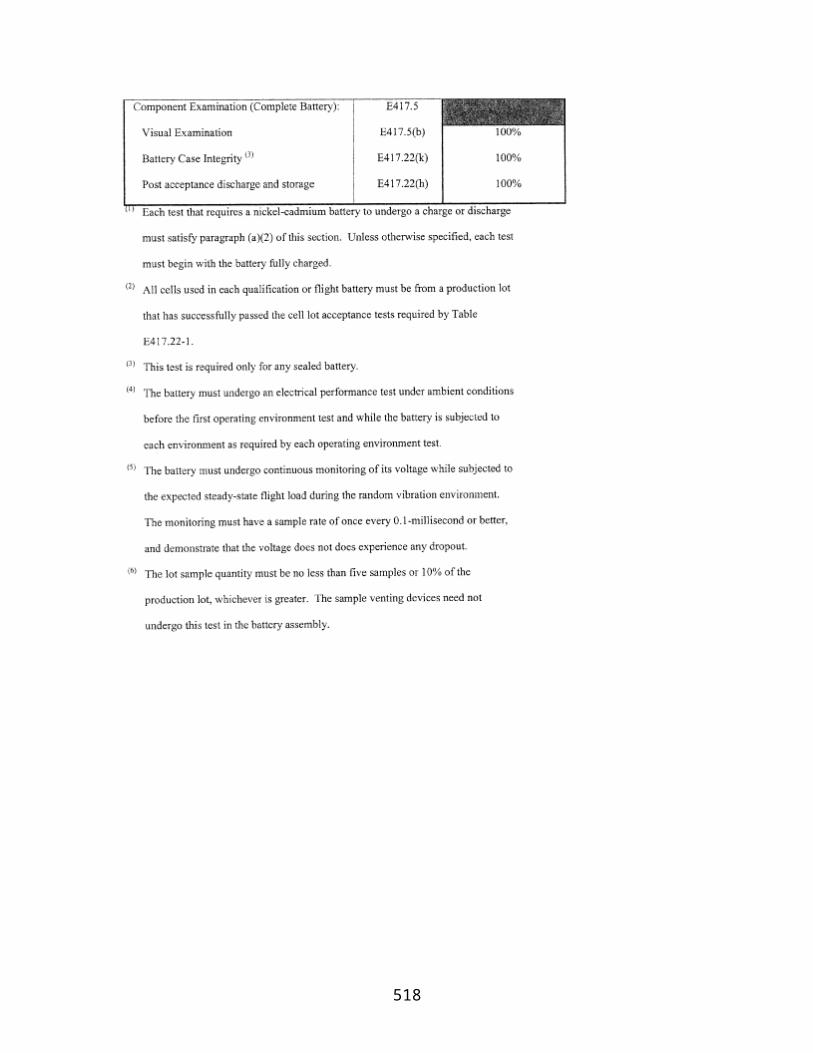
(i) Select a debris dispersion radius (Dmax) from table A–1 and a downrange distance (DOEZ) from table A–2 to define an overflight exclusion zone for the guided suborbital launch vehicle or orbital launch vehicle class selected in paragraph (c)(1)(i).
(ii) An overflight exclusion zone is described by the intersection of the following boundaries, which are depicted in figure A–1:
(A) An applicant shall define an uprange boundary with a half-circle arc of radius Dmaxand a chord of length twice Dmaxconnecting the half-circle arc endpoints. The uprange boundary placement on a map has the chord midpoint positioned on the launch point with the chord oriented along an azimuth ±90°from the launch azimuth and the half-circle arc located uprange from the launch point.
(B) An applicant shall define the downrange boundary with a half-circle arc of radius Dmaxand a chord of length twice Dmaxconnecting the half-circle arc endpoints. The downrange boundary placement on a map has the chord midpoint intersecting the nominal flight azimuth line at a distance DOEZinches downrange with the chord oriented along an azimuth ±90°from the launch azimuth and the half-circle arc located downrange from the intersection of the chord and the flight azimuth line.
(C) Crossrange boundaries of an overflight exclusion zone are defined by two lines segments. Each is parallel to the flight azimuth with one to the left side and one to the right side of the flight azimuth line. Each line connects an uprange half-circle arc endpoint to a downrange half-circle arc endpoint as shown in figure A–1.
(iii) An applicant shall identify the overflight exclusion zone on a map that meets the requirements of paragraph (b).
(3) An applicant shall define and map a flight corridor using the following method:
(i) In accordance with paragraph (b), an applicant shall draw a flight corridor on one or more maps with the Dmaxorigin centered on the intended launch point and the flight corridor centerline (in the downrange direction) aligned with the initial flight azimuth. The flight corridor is depicted in figure A–2 and its line segment lengths are tabulated in table A–3.
(ii) An applicant shall define the flight corridor using the following boundary definitions:
(A) An applicant shall draw an uprange boundary, which is defined by an arc-line GB (figure A–2), directly uprange from and centered on the intended launch point with radius Dmax.
(B) An applicant shall draw line CF perpendicular to and centered on the flight azimuth line, and positioned 10 nm downrange from the launch point. The applicant shall use the length of line CF provided in table A–3 corresponding to the guided suborbital launch vehicle or orbital launch vehicle class selected in paragraph (c)(1)(i).
518

(C) An applicant shall draw line DE perpendicular to and centered on the flight azimuth line, and positioned 100 nm downrange from the launch point. The applicant shall use the length of line DE provided in table A–3 corresponding to the guided suborbital launch vehicle or orbital launch vehicle class selected in paragraph (c)(1)(i).
(D) Except for a guided suborbital launch vehicle, an applicant shall draw a downrange boundary, which is defined by line HI and is drawn perpendicular to and centered on the flight azimuth line, and positioned 5,000 nm downrange from the launch point. The applicant shall use the length of line HI provided in table A–3 corresponding to the orbital launch vehicle class selected in paragraph (c)(1)(i).
(E) An applicant shall draw crossrange boundaries, which are defined by three lines on the left side and three lines on the right side of the flight azimuth. An applicant shall construct the left flight corridor boundary according to the following, and as depicted in figure A–3 :
(1) The first line (line BC in figure A–3) is tangent to the uprange boundary arc, and ends at endpoint C of line CF, as depicted in figure A–3;
(2) The second line (line CD in figure A–3) begins at endpoint C of line BC and ends at endpoint D of line DH, as depicted in figure A–3;
(3) For all orbital launch vehicles, the third line (line DH in figure A–3) begins at endpoint D of line CD and ends at endpoint H of line HI, as depicted in figure A–3; and
(4) For a guided suborbital launch vehicle, the line DH begins at endpoint D of line CD and ends at a point tangent to the impact dispersion area drawn in accordance with paragraph (c)(4) and as depicted in figure A–4.
(F) An applicant shall repeat the procedure in paragraph (c)(3)(ii)(E) for the right side boundary.
(iii) An applicant shall identify the flight corridor on a map that meets the requirements of paragraph (b).
(4) For a guided suborbital launch vehicle, an applicant shall define a final stage impact dispersion area as part of the flight corridor and show the impact dispersion area on a map, as depicted in figure A–4, in accordance with the following:
(i) An applicant shall select an apogee altitude (Hap) for the launch vehicle final stage. The apogee altitude should equal the highest altitude intended to be reached by a guided suborbital launch vehicle launched from the launch point.
(ii) An applicant shall define the impact dispersion area by using an impact range factor [IP(Hap)] and a dispersion factor [DISP(Hap)] as shown below:
519

(A) An applicant shall calculate the impact range (D) for the final launch vehicle stage. An applicant shall set D equal to the maximum apogee altitude (Hap) multiplied by the impact range factor as shown below:
where: IP(Hap) = 0.4 for an apogee less than 100 km; and IP(Hap) = 0.7 for an apogee 100 km or greater.
(B) An applicant shall calculate the impact dispersion radius (R) for the final launch vehicle stage. An applicant shall set R equal to the maximum apogee altitude (Hap) multiplied by the dispersion factor as shown below:
where: DISP(Hap) = 0.05
(iii) An applicant shall draw the impact dispersion area on a map with its center on the predicted impact point. An applicant shall then draw line DH in accordance with paragraph (c)(3)(ii)(E)(4).
(d) Evaluate the Flight Corridor
(1) An applicant shall evaluate the flight corridor for the presence of any populated areas. If an applicant determines that no populated area is located within the flight corridor, then no additional steps are necessary.
(2) If a populated area is located in an overflight exclusion zone, an applicant may modify its proposal or demonstrate that there are times when no people are present or that the applicant has an agreement in place to evacuate the public from the overflight exclusion zone during a launch.
(3) If a populated area is located within the flight corridor, an applicant may modify its proposal and create another flight corridor pursuant to appendix A, use appendix B to narrow the flight corridor, or complete a risk analysis in accordance with appendix C.
Table A–1—Debris Dispersion Radius (Dmax) (in)
Orbital launch vehicles Suborbital launch vehicles
Small Medium Medium large Large Guided
87,600(1.20 nm)
111,600(1.53 nm)
127,200(1.74 nm)
156,000(2.14 nm)
96,000(1.32 nm)
520

Table A–2—Overflight Exclusion Zone Downrange Distance (Doez) (in)
Orbital launch vehicles Suborbital launch vehicles
Small Medium Medium large Large Guided
240,500(3.30 nm)
253,000(3.47 nm)
310,300(4.26 nm)
937,700(12.86 nm)
232,100(3.18 nm)
521
522

523

524

Appendix B to Part 420—Method for Defining a Flight Corridor
(a) Introduction
(1) This appendix provides a method to construct a flight corridor from a launch point for a guided suborbital launch vehicle or any one of the four weight classes of guided orbital launch vehicles from table 1, §420.19, using local meteorological data and a launch vehicle trajectory.
(2) A flight corridor is constructed in two sections—one section comprising a launch area and one section comprising a downrange area. The launch area of a flight corridor reflects the extent of launch vehicle debris impacts in the event of a launch vehicle failure and applying local meteorological conditions. The downrange area reflects the extent of launch vehicle debris impacts in the event of a launch vehicle failure and applying vehicle imparted velocity, malfunctions turns, and vehicle guidance and performance dispersions.
(3) A flight corridor includes an overflight exclusion zone in the launch area and, for a guided suborbital launch vehicle, an impact dispersion area in the downrange area. A flight corridor for a guided suborbital launch vehicle ends with an impact dispersion area and, for the four classes of guided orbital launch vehicles, 5,000 nautical miles (nm) from the launch point, or where the IIP leaves the surface of the Earth, whichever is shorter.
(b) Data Requirements
(1) Launch area data requirements. An applicant shall satisfy the following data requirements to perform the launch area analysis of this appendix. The data requirements are identified in table B–1 along with sources where data acceptable to the FAA may be obtained.
(i) An applicant must select meteorological data that meet the specifications in table B–1 for the proposed launch site.
Table B–1—Launch Area Data Requirements
Data category Data item Data source
Meteorological Data
Local statistical wind data as a function of altitude up to 50,000 feet. Required data include: altitude (ft), atmospheric density (slugs/ft3), mean East/West meridianal (u) and North/South zonal (v) wind (ft/sec), standard deviation of u and v wind (ft/sec), correlation coefficient,
These data may be obtained from:Global Gridded Upper Air Statistics, Climate Applications Branch National Climatic Data Center.
525
number of observations and wind percentile (%)
Nominal Trajectory Data
State vector data as function of time after liftoff in topocentric launch point centered X,Y,Z,X,Y,Z coordinates with the X-axis aligned with the flight azimuth. Trajectory time intervals shall not be greater than one second. XYZ units are in feet and X,Y,Z units are in ft/sec
Actual launch vehicle trajectory data; or trajectory generation software that meets the requirements of paragraph (b)(1)(ii).
Debris Data A fixed ballistic coefficient equal to 3 lbs/ft2is used for the launch area
N/A.
Geographical Data
Launch point geodetic latitude on a WGS–84 ellipsoidal Earth model
Geographical surveys or Global Positioning System.
Launch point longitude on an ellipsoidal Earth model
Maps using scales of not less than 1:250,000 inches per inch within 100 nm of a launch point and 1:20,000,000 inches per inch for distances greater than 100 nm from a launch point
Map types with scale and projection information are listed in the Defense Mapping Agency, Public Sale, Aeronautical Charts and Publications Catalog. The catalog and maps may be ordered through the U.S. Dept. of Commerce, National Oceanic and Atmospheric Administration, National Ocean Service.
(ii) For a guided orbital launch vehicle, an applicant shall obtain or create a launch vehicle nominal trajectory. An applicant may use trajectory data from a launch vehicle manufacturer or generate a trajectory using trajectory simulation software. Trajectory time intervals shall be no greater than one second. If an applicant uses a trajectory computed with commercially available software, the software must calculate the trajectory using the following parameters, or clearly and convincingly demonstrated equivalents:
(A) Launch location:
( 1 ) Launch point, using geodetic latitude and longitude to four decimal places; and
( 2 ) Launch point height above sea level.
(B) Ellipsoidal Earth:
526
( 1 ) Mass of Earth;
( 2 ) Radius of Earth;
( 3 ) Earth flattening factor; and
( 4 ) Gravitational harmonic constants (J2, J3, J4).
(C) Vehicle characteristics:
( 1 ) Mass as a function of time;
( 2 ) Thrust as a function of time;
( 3 ) Specific impulse (ISP) as a function of time; and
( 4 ) Stage dimensions.
(D) Launch events:
( 1 ) Stage burn times; and
( 2 ) Stage drop-off times.
(E) Atmosphere:
( 1 ) Density as a function of altitude;
( 2 ) Pressure as a function of altitude;
( 3 ) Speed of sound as a function of altitude; and
( 4 ) Temperature as a function of altitude.
(F) Winds:
(1) Wind direction as a function of altitude; and
(2) Wind magnitude as a function of altitude.
(I) Aerodynamics: drag coefficient as a function of mach number for each stage of flight showing subsonic, transonic and supersonic mach regions for each stage.
(iii) An applicant shall use a ballistic coefficient (β) of 3 lbs/ft2 for debris impact computations.
527

(iv) An applicant shall satisfy the map and plotting requirements for a launch area of appendix A, paragraph (b).
(2) Downrange area data requirements. An applicant shall satisfy the following data requirements to perform the downrange area analysis of this appendix.
(i) The launch vehicle weight class and method of generating a trajectory used in the launch area shall be used by an applicant in the downrange area as well. Trajectory time intervals must not be greater than one second.
(ii) An applicant shall satisfy the map and plotting data requirements for a downrange area of appendix A, paragraph (b).
(c) Construction of a Launch Area of a Flight Corridor
(1) An applicant shall construct a launch area of a flight corridor using the processes and equations of this paragraph for each trajectory position. An applicant shall repeat these processes at time points on the launch vehicle trajectory for time intervals of no greater than one second. When choosing wind data, an applicant shall use a time period of between one and 12 months.
(2) A launch area analysis must include all trajectory positions whose Z-values are less than or equal to 50,000 ft.
(3) Each trajectory time is denoted by the subscript “i”. Height intervals for a given atmospheric pressure level are denoted by the subscript “j'.
(4) Using data from the GGUAS CD-ROM, an applicant shall estimate the mean atmospheric density, maximum wind speed, height interval fall times and height interval debris dispersions for 15 mean geometric height intervals.
(i) The height intervals in the GGUAS source data vary as a function of the following 15 atmospheric pressure levels expressed in millibars: surface, 1000, 850, 700, 500, 400, 300, 250, 200, 150, 100, 70, 50, 30, 10. The actual geometric height associated with each pressure level varies depending on the time of year. An applicant shall estimate the mean geometric height over the period of months selected in subparagraph (1) of this paragraph for each of the 15 pressure levels as shown in equation B1.
where:
528

Hj= mean geometric height hm= geometric height for a given month nm= number of observations for a given month
k = number of wind months of interest
(ii) The atmospheric densities in the source data also vary as a function of the 15 atmospheric pressure levels. The actual atmospheric density associated with each pressure level varies depending on the time of year. An applicant shall estimate the mean atmospheric density over the period of months selected in accordance with subparagraph (1) of this paragraph for each of the 15 pressure levels as shown in equation B2.
where:
ρj= mean atmospheric density
_
ρm= atmospheric density for a given month
nm= number of observations for a given month
k = number of wind months of interest
(iii) An applicant shall estimate the algebraic maximum wind speed at a given pressure level as follows and shall repeat the process for each pressure level.
(A) For each month, an applicant shall calculate the monthly mean wind speed (Waz) for 360 azimuths using equation B3;
(B) An applicant shall select the maximum monthly mean wind speed from the 360 azimuths;
(C) An applicant shall repeat subparagraphs (c)(4)(iii)(A) and (B) for each month of interest; and
(D) An applicant shall select the maximum mean wind speed from the range of months. The absolute value of this wind is designated Wmaxfor the current pressure level.
529
(iv) An applicant shall calculate wind speed using the means for winds from the West (u) and winds from the North (v). An applicant shall use equation B3 to resolve the winds to a specific azimuth bearing.
where:
az = wind azimuth
u = West zonal wind component
v = North zonal wind component
Waz= mean wind speed at azimuth for each month
(v) An applicant shall estimate the interval fall time over a height interval assuming the initial descent velocity is equal to the terminal velocity (VT). An applicant shall use equations B4 through B6 to estimate the fall time over a given height interval.
where:
ΔHTj= height difference between two mean geometric heights
β= ballistic coefficient
_
ρx= mean atmospheric density for the corresponding mean geometric heights
VTj= terminal velocity
530
(vi) An applicant shall estimate the interval debris dispersion (Dj) by multiplying the interval fall time by the algebraic maximum mean wind speed (Wmax) as shown in equation B7.
(5) Once the Dj are estimated for each height interval, an applicant shall determine the total debris dispersion (Di) for each Ziusing a linear interpolation and summation exercise, as shown below in equation B8. An applicant shall use a launch point height of zero equal to the surface level of the nearest GGUAS grid location.
where:
n = number of height intervals below jth height interval
(6) Once all the Diradii have been calculated, an applicant shall produce a launch area flight corridor in accordance with the requirements of subparagraphs (c)(6)(i)–(iv).
(i) On a map meeting the requirements of appendix A, paragraph (b), an applicant shall plot the Xiposition location on the flight azimuth for the corresponding Ziposition;
(ii) An applicant shall draw a circle of radius Dicentered on the corresponding Xiposition; and
(iii) An applicant shall repeat the instructions in subparagraphs (c)(6)(i)–(ii) for each Diradius.
(iv) The launch area of a flight corridor is the enveloping line that encloses the outer boundary of the Dicircles as shown in Fig. B–1. The uprange portion of a flight corridor is described by a semi-circle arc that is a portion of either the most uprange Didispersion circle, or the overflight exclusion zone (defined by subparagraph (c)(7)), whichever is further uprange.
(7) An applicant shall define an overflight exclusion zone in the launch area in accordance with the requirements of appendix A, subparagraph (c)(2).
(8) An applicant shall draw the launch area flight corridor and overflight exclusion zone on a map or maps that meet the requirements of table B–1.
531
(d) Construction of a Downrange Area of a Flight Corridor
(1) The downrange area analysis estimates the debris dispersion for the downrange time points on a launch vehicle trajectory. An applicant shall perform the downrange area analysis using the processes and equations of this paragraph.
(2) The downrange area analysis shall include trajectory positions at a height (the Zi-values) greater than 50,000 feet and nominal trajectory IIP values less than or equal to 5,000 nm. For a guided suborbital launch vehicle, the final IIP value for which an applicant must account is the launch vehicle final stage impact point. Each trajectory time shall be one second or less and is denoted by the subscript “i'.
(3) An applicant shall compute the downrange area of a flight corridor boundary in four steps, from each trajectory time increment: determine a reduction ratio factor; calculate the launch vehicle position after simulating a malfunction turn; rotate the state vector after the malfunction turn in the range of three degrees to one degree as a function of Xidistance downrange; and compute the IIP of the resulting trajectory. The locus of IIPs describes the boundary of the downrange area of a flight corridor. An applicant shall use the following subparagraphs, (d)(3)(i)–(v), to compute the downrange area of the flight corridor boundary:
(i) Compute the downrange Distance to the final IIP position for a nominal trajectory as follows:
(A) Using equations B30 through B69, determine the IIP coordinates (φmax, λmax) for the nominal state vector before the launch vehicle enters orbit where α in equation B30 is the nominal flight azimuth angle measured from True North.
(B) Using the range and bearing equations of appendix A, paragraph (b)(3), determine the distance (Smax) from the launch point coordinates (φlp, λlp) to the IIP coordinates (φmax, λmax) computed in accordance with (3)(i)(A) of this paragraph.
532
(C) The distance for Smaxmay not exceed 5000 nm. In cases when the actual value exceeds 5000 nm the applicant shall use 5000 nm for Smax.
(ii) Compute the reduction ratio factor (Fn) for each trajectory time increment as follows:
(A) Using equations B30 through B69, determine the IIP coordinates (φi, λi) for the nominal state vector where α in equation B30 is the nominal flight azimuth angle measured from True North.
(B) Using the range and bearing equations of appendix A, paragraph (b)(3), determine the distance (Si) from the launch point coordinates (φlp, λlp) to the IIP coordinates (φi, λi) computed in (3)(ii)(A) of this paragraph.
(C) The reduction ratio factor is:
(iii) An applicant shall compute the launch vehicle position and velocity components after a simulated malfunction turn for each Xiusing the following method.
(A) Turn duration (Δt) = 4 sec.
(B) Turn angle (Θ)
The turn angle equations perform a turn in the launch vehicle's yaw plane, as depicted in figure B–2.
533

(C) Launch vehicle velocity magnitude at the beginning of the turn (Vb) and velocity magnitude at the end of the turn (Ve)
(D) Average velocity magnitude over the turn duration (V)
(E) Velocity vector path angle (γi) at turn epoch
(F) Launch vehicle position components at the end of turn duration
534

where: g1= 32.17405 ft/sec2
(G) Launch vehicle velocity components at the end of turn duration
(iv) An applicant shall rotate the trajectory state vector at the end of the turn duration to the right and left to define the right-lateral flight corridor boundary and the left-lateral flight corridor boundary, respectively. An applicant shall perform the trajectory rotation in conjunction with a trajectory transformation from the X90, Y90, Z90, X90, Y90, Z90, components to E, N, U, E, N, U. The trajectory subscripts “R” and “L” from equations B15 through B26 have been discarded to reduce the number of equations. An applicant shall transform from to E,N,U,E,N,Uto E,F,G,E,F,G. An applicant shall use the equations of paragraph (d)(3)(iv)(A)–(F) to produce the EFG components necessary to estimate each instantaneous impact point.
(A) An applicant must calculate the flight angle (α)
535
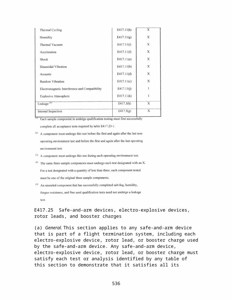
(B) An applicant shall transform X90,Y90,Z90to E,N,U
(C) An applicant shall transform to X90, Y90, Z90to E, N, U.
(D) An applicant shall transform the launch point coordinates (φ0λ0,h0) to E0,F0,G0
(E) An applicant shall transform E,N,U to E90,F90,G90
536

(F) An applicant shall transform to E,N,UTO E,F,G
(v) The IIP computation implements an iterative solution to the impact point problem. An applicant shall solve equations B46 through B69, with the appropriate substitutions, up to a maximum of five times. Each repetition of the equations provides a more accurate prediction of the IIP. An applicant shall use the required IIP computations of paragraphs (d)(3)(v)(A)–(W) below. An applicant shall use this IIP computation for both the left-and right-lateral offsets. The IIP computations will result in latitude and longitude pairs for the left-lateral flight corridor boundary and the right-lateral flight corridor boundary. An applicant shall use the lines connecting the latitude and longitude pairs to describe the entire downrange area boundary of the flight corridor up to 5000 nm or a final stage impact dispersion area.
(A) An applicant shall approximate the radial distance (rk,l) from the geocenter to the IIP. The distance from the center of the Earth ellipsoid to the launch point shall be used for the initial approximation of rk,las shown in equation B46.
(B) An applicant shall compute the radial distance (r) from the geocenter to the launch vehicle position.
If r < rk,lthen the launch vehicle position is below the Earth's surface and an impact point cannot be computed. An applicant must restart the calculations with the next trajectory state vector.
(C) An applicant shall compute the inertial velocity components.
537
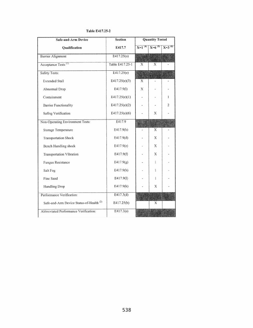
where: ω = 4.178074×10⁻³deg/sec
(D) An applicant shall compute the magnitude of the inertial velocity vector.
(E) An applicant shall compute the eccentricity of the trajectory ellipse multiplied by the cosine of the eccentric anomaly at epoch εc).
where: K = 1.407644×1016 ft3 /sec2
(F) An applicant shall compute the semi-major axis of the trajectory ellipse (at ).
If at0 or atthen the trajectory orbit is not elliptical, but is hyperbolic or parabolic, and an impact point cannot be computed. The launch vehicle has achieved escape velocity and the applicant may terminate computations.
(G) An applicant shall compute the eccentricity of the trajectory ellipse multiplied by the sine of the eccentric anomaly at epoch εs).
(H) An applicant shall compute the eccentricity of the trajectory ellipse squared ε2 ).
If at(1−ε)−aE] > 0 and ε ≥ 0 then the trajectory perigee height is positive and an impact point cannot be computed. The launch vehicle has achieved Earth orbit and the applicant may terminate computations.
(I) An applicant shall compute the eccentricity of the trajectory ellipse multiplied by the cosine of the eccentric anomaly at impact (εck).
538

(J) An applicant shall compute the eccentricity of the trajectory ellipse multiplied by the sine of the eccentric anomaly at impact (εsk).
If εsk< 0 then the trajectory orbit does not intersect the Earth's surface and an impact point cannot be computed. The launch vehicle has achieved Earth orbit and the applicant may terminate computations.
(K) An applicant shall compute the cosine of the difference between the eccentric anomaly at impact and the eccentric anomaly at epoch (Δεck).
(L) An applicant shall compute the sine of the difference between the eccentric anomaly at impact and the eccentric anomaly at epoch (Δεsk).
(M) An applicant shall compute the f-series expansion of Kepler's equations.
(N) An applicant shall compute the g-series expansion of Kepler's equations.
(O) An applicant shall compute the E,F,G coordinates at impact (Ei,Fi,Gi).
(P) An applicant shall approximate the distance from the geocenter to the launch vehicle position at impact (rk,2).
539
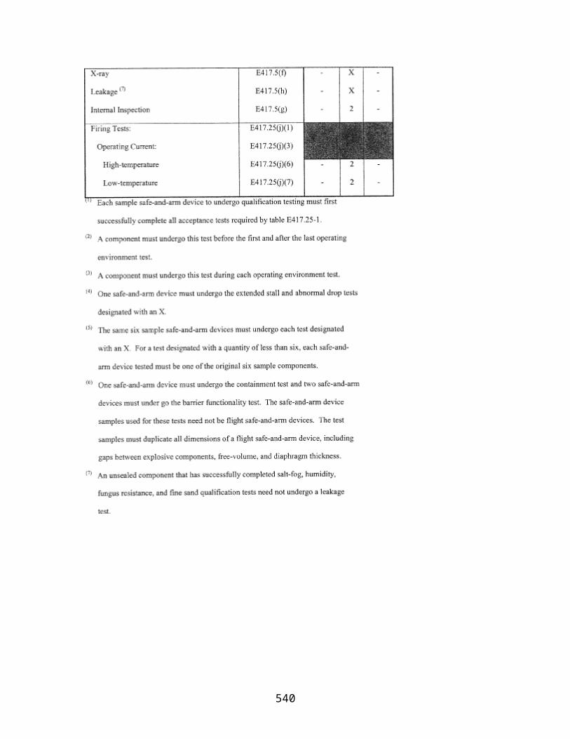
where:
aE= 20925646.3255 ft
e2 = 0.00669437999013
(Q) An applicant shall let rk+1,1= rk,2, substitute rk+1,1for rk,1in equation B55 and repeat equations B55—B64 up to four more times increasing “k” by an increment of one on each loop (e.g. kε{1, 2, 3, 4, 5}). If |r5,1−r5,2| > 1 then the iterative solution does not converge and an impact point does not meet the accuracy tolerance of plus or minus one foot. An applicant must try more iterations, or restart the calculations with the next trajectory state vector.
(R) An applicant shall compute the difference between the eccentric anomaly at impact and the eccentric anomaly at epoch (Δε).
(S) An applicant shall compute the time of flight from epoch to impact (t).
(T) An applicant shall compute the geocentric latitude at impact (φ').
Where: +90°>φ′i> −90°
(U) An applicant shall compute the geodetic latitude at impact (φ).
540

Where: +90°>φi> −90°
(V) An applicant shall compute the East longitude at impact (λ).
(W) If the range from the launch point to the impact point is equal to or greater than 5000 nm, an applicant shall terminate IIP computations.
(4) For a guided suborbital launch vehicle, an applicant shall define a final stage impact dispersion area as part of the flight corridor and show the area on a map using the following procedure:
(i) For equation B70 below, an applicant shall use an apogee altitude (Hap) corresponding to the highest altitude reached by the launch vehicle final stage in the applicant's launch vehicle trajectory analysis done in accordance with paragraph (b)(1)(ii).
(ii) An applicant shall define the final stage impact dispersion area by using a dispersion factor [DISP(Hap)] as shown below. An applicant shall calculate the impact dispersion radius (R) for the final launch vehicle stage. An applicant shall set R equal to the maximum apogee altitude (Hap) multiplied by the dispersion factor as shown below:
where: DISP(Hap) = 0.05
(5) An applicant shall combine the launch area and downrange area flight corridor and any final stage impact dispersion area for a guided suborbital launch vehicle.
(i) On the same map with the launch area flight corridor, an applicant shall plot the latitude and longitude positions of the left and right sides of the downrange area of the flight corridor calculated in accordance with subparagraph (d)(3).
(ii) An applicant shall connect the latitude and longitude positions of the left side of the downrange area of the flight corridor sequentially starting with the last IIP calculated on the left side and ending with the first IIP calculated on the left side. An applicant shall repeat this procedure for the right side.
(iii) An applicant shall connect the left sides of the launch area and downrange portions of the flight corridor. An applicant shall repeat this procedure for the right side.
(iv) An applicant shall plot the overflight exclusion zone defined in subparagraph (c)(7).
541

(v) An applicant shall draw any impact dispersion area on the downrange map with the center of the impact dispersion area on the launch vehicle final stage impact point obtained from the applicant's launch vehicle trajectory analysis done in accordance with subparagraph (b)(1)(ii).
(e) Evaluate the Launch Site
(1) An applicant shall evaluate the flight corridor for the presence of populated areas. If no populated area is located within the flight corridor, then no additional steps are necessary.
(2) If a populated area is located in an overflight exclusion zone, an applicant may modify its proposal or demonstrate that there are times when no people are present or that the applicant has an agreement in place to evacuate the public from the overflight exclusion zone during a launch.
(3) If a populated area is located within the flight corridor, an applicant may modify its proposal or complete an overflight risk analysis in accordance with appendix C.
542

Appendix C to Part 420—Risk Analysis
(a) Introduction
(1) This appendix provides a method for an applicant to estimate the expected casualty (Ec) for a launch of a guided expendable launch vehicle using a flight corridor generated either by appendix A or appendix B. This appendix also provides an applicant options to simplify the method where population at risk is minimal.
(2) An applicant shall perform a risk analysis when a populated area is located within a flight corridor defined by either appendix A or appendix B. If the estimated expected casualty exceeds 30×10−6, an applicant may either modify its proposal, or if the flight corridor used was generated by the appendix A method, use the appendix B method to narrow the flight corridor and then redo the overflight risk analysis pursuant to this appendix. If the estimated expected casualty still exceeds 30×10−6the FAA will not approve the location of the proposed launch point.
(b) Data Requirements
(1) An applicant shall obtain the data specified by subparagraphs (b)(2) and (3) and summarized in table C–1. Table C–1 provides sources where an applicant may obtain data acceptable to the FAA. An applicant must also employ the flight corridor information from appendix A or B, including flight azimuth and, for an appendix B flight corridor, trajectory information.
(2) Population data. Total population (N) and the total landmass area within a populated area (A) are required. Population data up to and including 100 nm from the launch point are required at the U.S. census block group level. Population data downrange from 100 nm are required at no greater than 1° × 1° latitude/longitude grid coordinates.
(3) Launch vehicle data. Launch vehicle data consist of the launch vehicle failure probability (Pf), the launch vehicle effective casualty area (Ac), trajectory position data, and the overflight dwell time (td). The failure probability is a constant (Pf= 0.10) for a guided orbital or suborbital expendable launch vehicle. Table C–3 provides effective casualty area data based on IIP range. Trajectory position information is provided from distance computations provided by this appendix for an appendix A flight corridor, or trajectory data used in appendix B for an appendix B flight corridor. The dwell time (td) may be determined from trajectory data produced when creating an appendix B flight corridor.
Table C–1—Overflight Analysis Data Requirements
Data category Data item Data source
543
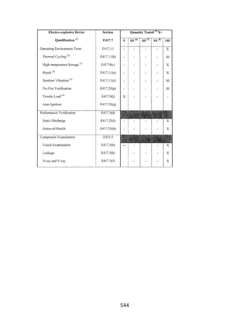
Population Data
Total population within a populated area (N)
Within 100 nm of the launch point: U.S. census data at the census block-group level. Downrange from 100 nm beyond the launch point, world population data are available from:
Total landmass area within the populated area (A)
Carbon Dioxide Information Analysis Center (CDIAC) Oak Ridge National LaboratoryDatabase—Global Population Distribution (1990), Terrestrial Area and Country Name Information on a One by One Degree Grid Cell Basis (DB1016 (8–1996)
Launch Vehicle Data
Failure probability—Pf= 0.10
N/A.
Effective casualty area (Ac)
See table C–3.
Overflight dwell time Determined by range from the launch point or trajectory used by applicant.
Nominal trajectory data (for an appendix B flight corridor only)
See appendix B, table B–1.
(c) Estimating Corridor Casualty Expectation
(1) A corridor casualty expectation [EC(Corridor)] estimate is the sum of the expected casualty measurement of each populated area inside a flight corridor.
(2) An applicant shall identify and locate each populated area in the proposed flight corridor.
(3) An applicant shall determine the probability of impact in each populated area using the procedures in subparagraphs (5) or (6) of this paragraph. Figures C–1 and C–2 illustrate an area considered for probability of impact (Pi) computations by the dashed-lined box around the populated area within a flight corridor, and figure C–3 illustrates a populated area in a final stage impact dispersion area. An applicant shall then estimate the ECfor each populated area in accordance with subparagraphs (7) and (8) of this paragraph.
(4) The Picomputations do not directly account for populated areas whose areas are bisected by an appendix A flight corridor centerline or an appendix B nominal trajectory ground trace. Accordingly, an applicant must evaluate Pifor each of the bi-sections as two separate populated areas, as shown in figure C–4, which shows one bi-section to the left of an appendix A flight corridor's centerline and one to its right.
544
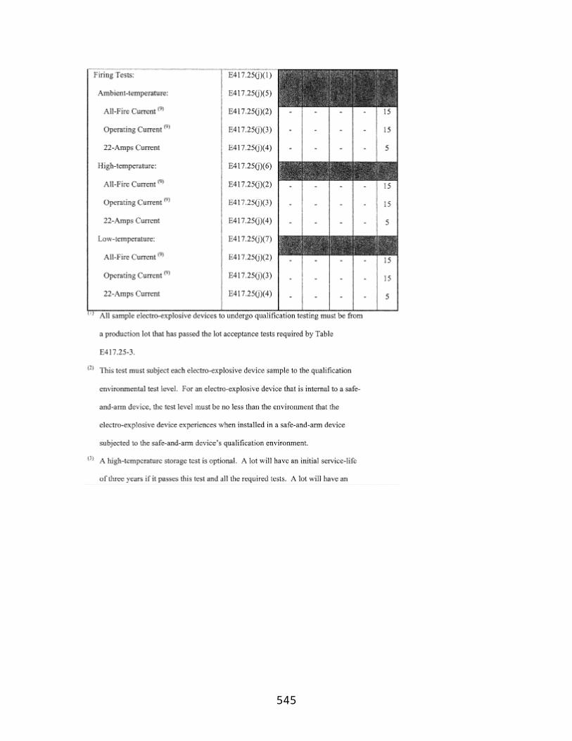
(5) Probability of impact (Pi) computations for a populated area in an appendix A flight corridor. An applicant shall compute Pifor each populated area using the following method:
(i) For the launch and downrange areas, but not for a final stage impact dispersion area for a guided suborbital launch vehicle, an applicant shall compute Pifor each populated area using the following equation:
where:
x1, x2= closest and farthest downrange distance (nm) along the flight corridor centerline to the populated area (see figure C–1)
y1, y2= closest and farthest cross range distance (nm) to the populated area measured from the flight corridor centerline (see figure C–1)
σy= one-third of the cross range distance from the centerline to the flight corridor boundary (see figure C–1)
exp = exponential function (ex )
Pf= probability of failure = 0.10
R= IIP range rate (nm/sec) (see table C–2)
C = 643 seconds (constant)
Table C–2—IIP Range Rate vs. IIP Range
IIP range(nm)
IIP range rate(nm/s)
0–75 0.75
76–300 1.73
301–900 4.25
901–1700 8.85
1701–2600 19.75
545

2601–3500 42.45
3501–4500 84.85
4501–5250 154.95
(ii) For each populated area within a final stage impact dispersion area, an applicant shall compute Piusing the following method:
(A) An applicant shall estimate the probability of final stage impact in the x and y sectors of each populated area within the final stage impact dispersion area using equations C2 and C3:
where:
X1, X2= closest and farthest downrange distance, measured along the flight corridor centerline, measured from the nominal impact point to the populated area (see figure C–3)
σx= one-third of the impact dispersion radius (see figure C–3)
exp = exponential function (ex )
where:
y1, y2= closest and farthest cross range distance to the populated area measured from the flight corridor centerline (see figure C–3)
σy= one-third of the impact dispersion radius (see figure C–3)
exp = exponential function (ex )
546

(B) If a populated area intersects the impact dispersion area boundary so that the x2or y2distance would otherwise extend outside the impact dispersion area, the x2or y2distance should be set equal to the impact dispersion area radius. The x2distance for populated area A in figure C–3 is an example. If a populated area intersects the flight azimuth, an applicant shall solve equation C3 by obtaining the solution in two parts. An applicant shall determine, first, the probability between y1= 0 and y2= a and, second, the probability between y1= 0 and y2= b, as depicted in figure C–4. The probability Pyis then equal to the sum of the probabilities of the two parts. If a populated area intersects the line that is normal to the flight azimuth on the impact point, an applicant shall solve equation C2 by obtaining the solution in two parts in the same manner as with the values of x.
(C) An applicant shall calculate the probability of impact for each populated area using equation C4 below:
where: Ps= 1−Pf= 0.90
(6) Probability of impact computations for a populated area in an appendix B flight corridor. An applicant shall compute Piusing the following method:
(i) For the launch and downrange areas, but not for a final stage impact dispersion area for a guided suborbital launch vehicle, an applicant shall compute Pifor each populated area using the following equation:
547

where:
y1,y2= closest and farthest cross range distance (nm) to a populated area measured from the nominal trajectory IIP ground trace (see figure C–2)
σy= one-third of the cross range distance (nm) from nominal trajectory to the flight corridor boundary (see figure C–2)
exp = exponential function (ex )
Pf= probability of failure = 0.10
t = flight time from lift-off to orbital insertion (seconds)
td= overflight dwell time (seconds)
(ii) For each populated area within a final stage impact dispersion area, an applicant shall compute Piusing the following method:
(A) An applicant shall estimate the probability of final stage impact in the x and y sectors of each populated area within the final stage impact dispersion area using equations C6 and C7:
where:
x1, x2= closest and farthest downrange distance, measured along nominal trajectory IIP ground trace, measured from the nominal impact point to the populated area (see figure C–3)
σx= one-third of the impact dispersion radius (see figure C–3)
exp = exponential function (ex )
548

where:
y1, y2= closest and farthest cross range distance to the populated area measured from the nominal trajectory IIP ground trace (see figure C–3)
σy= one-third of the impact dispersion radius (see figure C–3)
exp = exponential function (ex )
(B) If a populated area intersects the impact dispersion area boundary so that the x2or y2distance would otherwise extend outside the impact dispersion area, the x2or y2distance should be set equal to the impact dispersion area radius. The x2distance for populated area A in figure C–3 is an example. If a populated area intersects the flight azimuth, an applicant shall solve equation C7 by obtaining the solution in two parts. An applicant shall determine, first, the probability between y1= 0 and y2= a and, second, the probability between y1= 0 and y2= b, as depicted in figure C–4. The probability Pyis then equal to the sum of the probabilities of the two parts. If a populated area intersects the line that is normal to the flight azimuth on the impact point, an applicant shall solve equation C6 by obtaining the solution in two parts in a similar manner with the values of x.
(C) An applicant shall calculate the probability of impact for each populated area using equation C8 below:
where: Ps= 1−Pf= 0.90
549
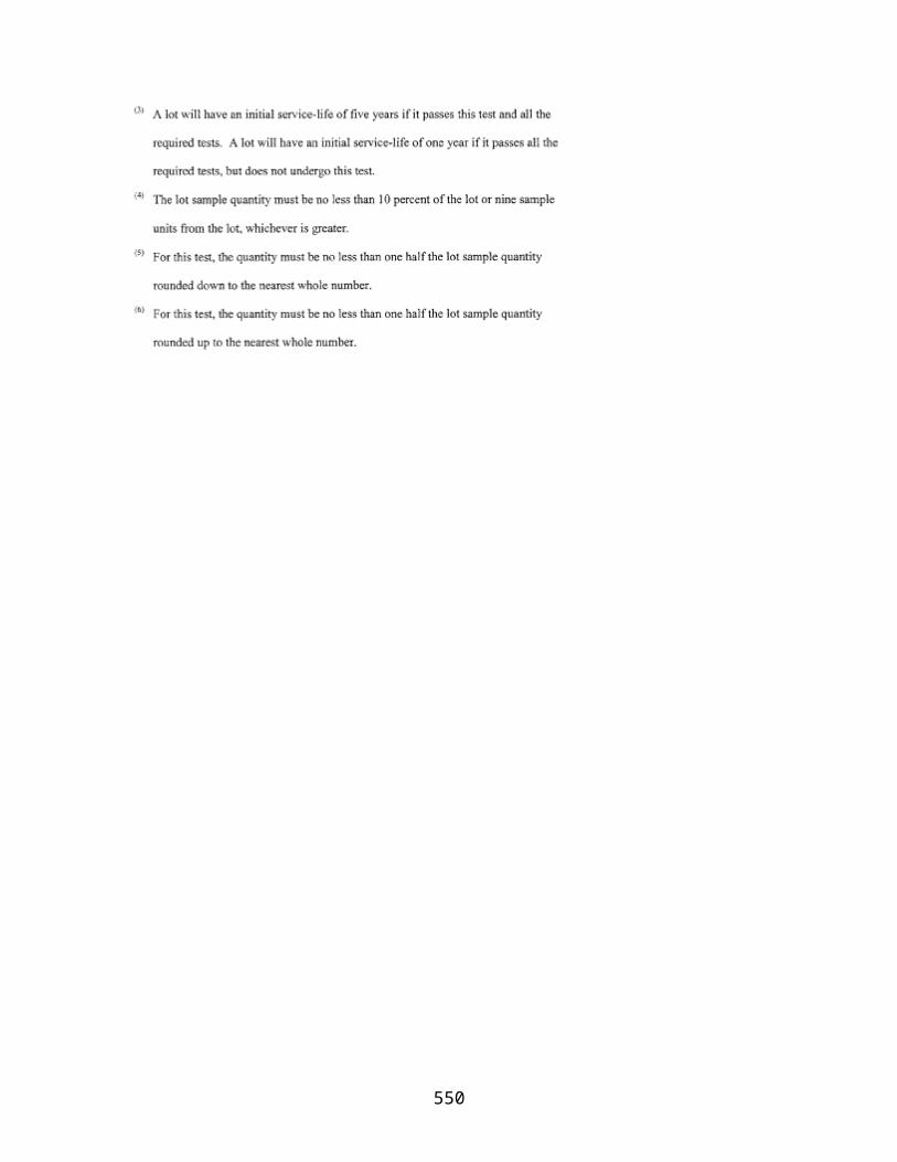
550

(7) Using the Picalculated in either subparagraph (c)(5) or (6) of this paragraph, an applicant shall calculate the casualty expectancy for each populated area within the flight corridor in accordance with equation C9. Eckis the casualty expectancy for a given populated area as shown in equation C9, where individual populated areas are designated with the subscript “k”.
where:
Ac= casualty area (from table C–3)
551

Ak= populated area
Nk= population in Ak
Table C–3—Effective Casualty Area (Miles2) as a Function of IIP Range (NM)
Orbital launch vehicles
Suborbital launchvehicles
Instantaneous impact point range (nautical miles) Small Medium
Medium large Large Guided
0–49 3.14 x 10⁻²
1.28 x 10⁻¹
4.71 x 10⁻² 8.59 x 10⁻²
4.3 x 10⁻¹
50–1749 2.47 x 10⁻²
2.98 x 10⁻²
9.82 x 10⁻³ 2.45 x 10⁻²
1.3 x 10⁻¹
1750–5000 3.01 x 10⁻⁴
5.52 x 10⁻³
7.82 x 10⁻³ 1.14 x 10⁻²
3.59 x 10⁻⁶
(8) An applicant shall estimate the total corridor risk using the following summation of risk:
(9) Alternative casualty expectancy (EC) analyses. An applicant may employ specified variations to the analysis defined by subparagraphs (c)(1)–(8). Those variations are identified in subparagraphs (9)(i) through (vi) of this paragraph. Subparagraphs (i) through (iv) permit an applicant to make conservative assumptions that would lead to an overestimation of the corridor ECcompared with the analysis defined by subparagraphs (c)(1)–(8). In subparagraphs (v) and (vi), an applicant that would otherwise fail the analysis prescribed by subparagraphs (c)(1)–(8) may avoid (c)(1)–(8)'s overestimation of the probability of impact in each populated area. An applicant employing a variation shall identify the variation used, show and discuss the specific assumptions made to modify the analysis defined by subparagraphs (c)(1)–(8), and demonstrate how each assumption leads to overestimation of the corridor ECcompared with the analysis defined by subparagraphs (c)(1)–(c)(8).
(i) Assume that Pxand Pyhave a value of 1.0 for all populated areas.
(ii) Combine populated areas into one or more larger populated areas, and use a population density for the combined area or areas equal to the most densely populated area.
552
(iii) For any given populated area, assume Pyhas a value of one.
(iv) For any given Pxsector (an area spanning the width of a flight corridor and bounded by two time points on the trajectory IIP ground trace) assume Pyhas a value of one and use a population density for the sector equal to the most densely populated area.
(v) For a given populated area, divide the populated area into smaller rectangles, determine Pifor each individual rectangle, and sum the individual impact probabilities to determine Pifor the entire populated area.
(vi) For a given populated area, use the ratio of the populated area to the area of the Pirectangle from the subparagraph (c)(1)–(8) analysis.
(d) Evaluation of Results
(1) If the estimated expected casualty does not exceed 30×10−6, the FAA will approve the launch site location.
(2) If the estimated expected casualty exceeds 30×10−6, then an applicant may either modify its proposal, or, if the flight corridor used was generated by the appendix A method, use the appendix B method to narrow the flight corridor and then perform another appendix C risk analysis.
[Docket No. FAA–1999–5833, 65 FR 62861, Oct. 19, 2000, as amended by Amdt. 420–2, 71 FR 51972, Aug. 31, 2006]
553

Appendix D to Part 420—Impact Dispersion Areas and Casualty Expectancy Estimate for an Unguided Suborbital Launch Vehicle
(a) Introduction
(1) This appendix provides a method for determining the acceptability of the location of a launch point from which an unguided suborbital launch vehicle would be launched. The appendix describes how to define an overflight exclusion zone and impact dispersion areas, and how to evaluate whether the public risk presented by the launch of an unguided suborbital launch vehicle remains at acceptable levels.
(2) An applicant shall base its analysis on an unguided suborbital launch vehicle whose final launch vehicle stage apogee represents the intended use of the launch point.
(3) An applicant shall use the apogee of each stage of an existing unguided suborbital launch vehicle with a final launch vehicle stage apogee equal to the one proposed, and calculate each impact range and dispersion area using the equations provided.
(4) This appendix also provides a method for performing an impact risk analysis that estimates the expected casualty (Ec) within each impact dispersion area. This appendix provides an applicant options to simplify the method where population at risk is minimal.
(5) If the estimated Ecis less than or equal to 30×10−6,the FAA will approve the launch point for unguided suborbital launch vehicles. If the estimated Ecexceeds 30×10−6,the proposed launch point will fail the launch site location review.
(b) Data Requirements
(1) An applicant shall employ the apogee of each stage of an existing unguided suborbital launch vehicle whose final stage apogee represents the maximum altitude to be reached by unguided suborbital launch vehicles launched from the launch point. The apogee shall be obtained from one or more actual flights of an unguided suborbital launch vehicle launched at an 84 degree elevation.
(2) An applicant shall satisfy the map and plotting data requirements of appendix A, paragraph (b).
(3) Population data. An applicant shall use total population (N) and the total landmass area within a populated area (A) for all populated areas within an impact dispersion area. Population data up to and including 100 nm from the launch point are required at the U.S. census block group level. Population data downrange from 100 nm are required at no greater than 1° × 1° latitude/longitude grid coordinates.
(c) Overflight Exclusion Zone and Impact Dispersion Areas
554
(1) An applicant shall choose a flight azimuth from a launch point.
(2) An applicant shall define an overflight exclusion zone as a circle with a radius of 1600 feet centered on the launch point.
(3) An applicant shall define an impact dispersion area for each stage of the suborbital launch vehicle chosen in accordance with subparagraph (b)(1) in accordance with the following:
(i) An applicant shall calculate the impact range for the final launch vehicle stage (Dn). An applicant shall set Dnequal to the last stage apogee altitude (Hn) multiplied by an impact range factor [IP(Hn)] in accordance with the following:
where:
IP(Hn) = 0.4 for an apogee less than 100 km, and
IP(Hn) = 0.7 for an apogee of 100 km or greater.
(ii) An applicant shall calculate the impact range for each intermediate stage (Di), where i ε {1, 2, 3, . . . (n− 1)}, and where n is the total number of launch vehicle stages. Using the apogee altitude (Hi) of each intermediate stage, an applicant shall use equation D1 to compute the impact range of each stage by substituting Hifor Hn. An applicant shall use the impact range factors provided by equation D1.
(iii) An applicant shall calculate the impact dispersion radius for the final launch vehicle stage (Rn). An applicant shall set Rnequal to the last stage apogee altitude (Hn) multiplied by an impact dispersion factor [DISP(Hn)] in accordance with the following:
where:
DISP(Hn) = 0.4 for an apogee less than 100 km, and
DISP(Hn) = 0.7 for an apogee of 100 km or greater.
(iv) An applicant shall calculate the impact dispersion radius for each intermediate stage (Ri), where i ε {1, 2, 3, . . . (n− 1)} and where n is the total number of launch vehicle stages. Using the apogee altitude (Hi) of each intermediate stage, an applicant shall use equation D2 to compute an impact dispersion radius of each stage by substituting Hifor Hn. An applicant shall use the dispersion factors provided by equation D2.
555

(4) An applicant shall display an overflight exclusion zone, each intermediate and final stage impact point (Dithrough Dn), and each impact dispersion area for the intermediate and final launch vehicle stages on maps in accordance with paragraph (b)(2).
(d) Evaluate the Overflight Exclusion Zone and Impact Dispersion Areas
(1) An applicant shall evaluate the overflight exclusion zone and each impact dispersion area for the presence of any populated areas. If an applicant determines that no populated area is located within the overflight exclusion zone or any impact dispersion area, then no additional steps are necessary.
(2) If a populated area is located in an overflight exclusion zone, an applicant may modify its proposal or demonstrate that there are times when no people are present or that the applicant has an agreement in place to evacuate the public from the overflight exclusion zone during a launch.
(3) If a populated area is located within any impact dispersion area, an applicant may modify its proposal and define a new overflight exclusion zone and new impact dispersion areas, or perform an impact risk analysis in accordance with paragraph (e).
(e) Impact Risk Analysis
(1) An applicant shall estimate the expected average number of casualties, EC, within the impact dispersion areas according to the following method:
(i) An applicant shall calculate the Ecby summing the impact risk for the impact dispersion areas of the final launch vehicle stage and all intermediate stages. An applicant shall estimate Ecfor the impact dispersion area of each stage by using equations D3 through D7 for each of the populated areas located within the impact dispersion areas.
556
(ii) An applicant shall estimate the probability of impacting inside the X and Y sectors of each populated area within each impact dispersion area using equations D3 and D4:
where:
x1, x2= closest and farthest downrange distance to populated area (see figure D–2)
σx= one-third of the impact dispersion radius (see figure D–2)
exp = exponential function (ex )
where:
y1, y2= closest and farthest cross range distance to the populated area (see figure D–2)
σy= one-third of the impact dispersion radius (see figure D–2)
exp = exponential function (ex )
557

(iii) If a populated area intersects the impact dispersion area boundary so that the x2or y2distance would otherwise extend outside the impact dispersion area, the x2or y2distance should be set equal to the impact dispersion area radius. The x2distance for populated area A in figure D–2 is an example.
(iv) If a populated area intersects the flight azimuth, an applicant shall solve equation D4 by obtaining the solution in two parts. An applicant shall determine, first, the probability between y1= 0 and y2= a and, second, the probability between y1= 0 and y2= b, as depicted in figure D–3. The probability Pyis then equal to the sum of the probabilities of the two parts. If a populated area intersects the line that is normal to the flight azimuth on the impact point, an applicant shall solve equation D3 by obtaining the solution in two parts in the same manner as with the values of x.
558
(v) An applicant shall calculate the probability of impact (Pi) for each populated area using the following equation:
where:
Ps= probability of success = 0.98
(vi) An applicant shall calculate the casualty expectancy for each populated area. Eckis the casualty expectancy for a given populated area as shown in equation D6, where individual populated areas are designated with the subscript “k”.
where:
k { {1, 2, 3, . . . , n}
Ac= casualty area (from table D–1)
Ak= populated area
Nk= population in Ak
559
Table D–1—Effective Casualty Area (Ac) vs. Impact Range
Impact range (nm)Effective casualty area
(miles2)
0–4 9×10⁻³
5–49 9×10⁻³
50–1,749 1.1×10⁻⁵
1,750–4,999 3.6×10⁻⁶
5,000–more 3.6×10⁻⁶
(vii) An applicant shall estimate the total risk using the following summation of risk:
(viii) Alternative casualty expectancy (Ec) analysis. An applicant may employ specified variations to the analysis defined by subparagraphs (d)(1)(i)–(vii). Those variations are identified in subparagraphs (viii)(A) through (F) of this paragraph. Subparagraphs (A) through (D) permit an applicant to make conservative assumptions that would lead to an overestimation of Eccompared with the analysis defined by subparagraphs (d)(1)(i)–(vii). In subparagraphs (E) and (F), an applicant that would otherwise fail the analysis prescribed by subparagraphs (d)(1)(i)–(vii) may avoid (d)(1)(i)–(vii)'s overestimation of the probability of impact in each populated area. An applicant employing a variation shall identify the variation used, show and discuss the specific assumptions made to modify the analysis defined by subparagraphs (d)(1)(i)–(vii), and demonstrate how each assumption leads to overestimation of the corridor Eccompared with the analysis defined by subparagraphs (d)(1)(i)–(vii).
(A) Assume that Pxand Pyhave a value of 1.0 for all populated areas.
(B) Combine populated areas into one or more larger populated areas, and use a population density for the combined area or areas equal to the most densely populated area.
(C) For any given populated area, assume Pxhas a value of one.
(D) For any given populated area, assume Pyhas a value of one.
(E) For a given populated area, divide the populated area into smaller rectangles, determine Pifor each individual rectangle, and sum the individual impact probabilities to determine Pifor the entire populated area.
560

(F) For a given populated area, use the ratio of the populated area to the area of the Pirectangle used in the subparagraph (d)(1)(i)–(vii) analysis.
(2) If the estimated expected casualty does not exceed 30 × 10−6, the FAA will approve the launch point.
(3) If the estimated expected casualty exceeds 30 × 10−6, then an applicant may modify its proposal and then repeat the impact risk analysis in accordance with this appendix D. If no set of impact dispersion areas exist which satisfy the FAA's risk threshold, the applicant's proposed launch site will fail the launch site location review.
561

Appendix E to Part 420—Tables for Explosive Site Plan
Table E–1—Quantity Distance Requirements for Solid Explosives
Quantity (lbs.) (over)
Quantity (lbs.) (not
over)
Public area distance (ft.) for division
1.1
Public area distance (ft.) for division
1.3
Intraline distance (ft.) for division
1.1
Intraline distance (ft.) for division
1.3
0 1,000 1,250 75 D = 18 W1/3 50
1,000 5,000 115 75
5,000 10,000 150 100
10,000 20,000 190 125
20,000 30,000 215 145
30,000 40,000 D = 40 W1/3 235 155
40,000 50,000 250 165
50,000 60,000 260 175
60,000 70,000 270 185
70,000 80,000 280 190
80,000 90,000 195 195
90,000 100,000 300 200
100,000 200,000 D=2.42 W0.577 375 250
200,000 250,000 413 275
250,000 300,000 D = 50 W1/3 450 300
300,000 400,000 525 350
400,000 500,000 600 400
500,000 1,000,000 800 500
Greater than 1,000,000
D = 50 W1/3 D = 8 W1/3 D = 5 W1/3
“D” equals the minimum separation distance in feet.
“W” equals the NEW of propellant.
Table E–2—Liquid Propellant Explosive Equivalents
562

Propellant combinations Explosive equivalent
LO2/LH2 The larger of: 8W2/3where W is the weight of LO2/LH2, or14% of W.
LO2/LH2+ LO2/RP–1 Sum of (20% for LO2/RP–1) + the larger of: 8W2/3where W is the weight of LO2/LH2, or14% of W.
LO2/R–1 20% of W up to 500,000 pounds plus 10% of W over 500,000 pounds, where W is the weight of LO2RP–1.
N2O4/N2H4(or UDMH or UDMH/N2H4Mixture)
10% of W, where W is the weight of the propellant.
Table E–3—Propellant Hazard and Compatibility Groupings and Factors To Be Used When Converting Gallons of Propellant Into Pounds
PropellantHazardgroup
Compatibilitygroup
Pounds/gallon At temperature °F
Hydrogen Peroxide II A 11.6 68
Hydrazine III C 8.4 68
Liquid Hydrogen III C 0.59 −423
Liquid Oxygen II A 9.5 −297
Nitrogen Tetroxide I A 12.1 68
RP–1 I C 6.8 68
UDMH III C 6.6 68
UDMH/Hydrazine III C 7.5 68
Table E–4—Hazard Group I
Pounds of propellant
Public area and
incompatible
Intragroup and
compatible
Pounds of propellant
Public area and
incompatible
Intragroup and
compatible
OverNot over
Distance in feet
Distance in feet Over Not over
Distance in feet
Distance in feet
0 100 30 25 5,000 6,000 80 60
100 200 35 30 6,000 7,000 85 65
563

200 300 40 35 7,000 8,000 85 65
300 400 45 35 8,000 9,000 90 70
400 500 50 40 9,000 10,000 90 70
500 600 50 40 10,000 15,000 95 75
600 700 55 40 15,000 20,000 100 80
700 800 55 45 20,000 25,000 105 80
800 900 60 45 25,000 30,000 110 85
900 1,000 60 45 30,000 35,000 110 85
1,000 2,000 65 50 35,000 40,000 115 85
2,000 3,000 70 55 40,000 45,000 120 90
3,000 4,000 75 55 45,000 50,000 120 90
4,000 5,000 80 60 50,000 60,000 125 95
60,000 70,000 130 95 500,000 600,000 185 140
70,000 80,000 130 100 600,000 700,000 190 145
80,000 90,000 135 100 700,000 800,000 195 150
90,000 100,000
135 105 800,000 900,000 200 150
100,000
125,000
140 110 900,000 1,000,000 205 155
125,000
150,000
145 110 1,000,000
2,000,000 235 175
150,000
175,000
150 115 2,000,000
3,000,000 255 190
175,000
200,000
155 115 3,000,000
4,000,000 265 200
200,000
250,000
160 120 4,000,000
5,000,000 275 210
250,000
300,000
165 125 5,000,000
6,000,000 285 215
300,000
350,000
170 130 6,000,000
7,000,000 295 220
350,000
400,000
175 130 7,000,000
8,000,000 300 225
564

400,000
450,000
180 135 8,000,000
9,000,000 305 230
450,000
500,000
180 135 9,000,000
10,000,000
310 235
Table E–5—Hazard Group II
Pounds of propellant
Public area and
incompatible
Intragroup and
compatiblePounds of propellant
Public area and
incompatible
Intragroup and
compatible
OverNot over
Distance in feet
Distance in feet Over Not over
Distance in feet
Distance in feet
0 100 60 30 50,000 60,000 250 125
100 200 75 35 60,000 70,000 255 130
200 300 85 40 70,000 80,000 260 130
300 400 90 45 80,000 90,000 265 135
400 500 100 50 90,000 100,000 270 135
500 600 100 50 100,000 125,000 285 140
600 700 105 55 125,000 150,000 295 145
700 800 110 55 150,000 175,000 305 150
800 900 115 60 175,000 200,000 310 155
900 1,000 120 60 200,000 250,000 320 160
1,000 2,000 130 65 250,000 300,000 330 165
2,000 3,000 145 70 300,000 350,000 340 170
3,000 4,000 150 75 350,000 400,000 350 175
4,000 5,000 160 80 400,000 450,000 355 180
5,000 6,000 165 80 450,000 500,000 360 180
6,000 7,000 170 85 500,000 600,000 375 185
7,000 8,000 175 85 600,000 700,000 385 190
8,000 9,000 175 90 700,000 800,000 395 195
9,000 10,000 180 90 800,000 900,000 405 200
10,000 15,000 195 95 900,000 1,000,000 410 205
565

15,000 20,000 205 100 1,000,000 2,000,000 470 235
20,000 25,000 215 105 2,000,000 3,000,000 505 255
25,000 30,000 220 110 3,000,000 4,000,000 535 265
30,000 35,000 225 110 4,000,000 5,000,000 555 275
35,000 40,000 230 115 5,000,000 6,000,000 570 285
40,000 45,000 235 120 6,000,000 7,000,000 585 295
45,000 50,000 240 120 7,000,000 8,000,000 600 300
8,000,000 9,000,000 610 305
9,000,000 10,000,000 620 310
Table E–6—Hazard Group III
Pounds of propellant
Public area and
incompatible
Intragroup and
compatiblePounds of propellant
Public area and
incompatible
Intragroup and
compatible
OverNot over
Distance in feet
Distance in feet Over Not over
Distance in feet
Distance in feet
0 100 600 30 60,000 70,000 1,200 130
100 200 600 35 70,000 80,000 1,200 130
200 300 600 40 80,000 90,000 1,200 135
300 400 600 45 90,000 100,000 1,200 135
400 500 600 50 100,000 125,000 1,800 140
500 600 600 50 125,000 150,000 1,800 145
600 700 600 55 150,000 175,000 1,800 150
700 800 600 55 175,000 200,000 1,800 155
800 900 600 60 200,000 250,000 1,800 160
900 1,000 600 60 250,000 300,000 1,800 165
1,000 2,000 600 65 300,000 350,000 1,800 170
2,000 3,000 600 70 350,000 400,000 1,800 175
3,000 4,000 600 75 400,000 450,000 1,800 180
4,000 5,000 600 80 450,000 500,000 1,800 180
5,000 6,000 600 80 500,000 600,000 1,800 185
566

6,000 7,000 600 85 600,000 700,000 1,800 190
7,000 8,000 600 85 700,000 800,000 1,800 195
8,000 9,000 600 90 800,000 900,000 1,800 200
9,000 10,000 600 90 900,000 1,000,000 1,800 205
10,000 15,000 1,200 95 1,000,000
2,000,000 1,800 235
15,000 20,000 1,200 100 2,000,000
3,000,000 1,800 255
20,000 25,000 1,200 105 3,000,000
4,000,000 1,800 265
25,000 30,000 1,200 110 4,000,000
5,000,000 1,800 275
30,000 35,000 1,200 110 5,000,000
6,000,000 1,800 285
35,000 40,000 1,200 115 6,000,000
7,000,000 1,800 295
40,000 45,000 1,200 120 7,000,000
8,000,000 1,800 300
45,000 50,000 1,200 120 8,000,000
9,000,000 1,800 305
50,000 60,000 1,200 125 9,000,000
10,000,000
1,800 310
Table E–7—Distances When Explosive Equivalents Apply
TNT equivalent weight of propellants Distance in feet
Not over To public areaIntraline
unbarricaded
100 1250 80
200 1250 100
300 1250 120
400 1250 130
500 1250 140
600 1250 150
567

700 1250 160
800 1250 170
900 1250 180
1,000 1250 190
1,500 1250 210
2,000 1250 230
3,000 1250 260
4,000 1250 280
5,000 1250 300
6,000 1250 320
7,000 1250 340
8,000 1250 360
9,000 1250 380
10,000 1250 400
15,000 1250 450
20,000 1250 490
25,000 1,250 530
30,000 1,250 560
35,000 1,310 590
40,000 1,370 620
45,000 1,425 640
50,000 1,475 660
55,000 1,520 680
60,000 1,565 700
65,000 1,610 720
70,000 1,650 740
75,000 1,685 770
80,000 1,725 780
85,000 1,760 790
90,000 1,795 800
568

95,000 1,825 820
100,000 1,855 830
125,000 2,115 900
150,000 2,350 950
175,000 2,565 1,000
200,000 2,770 1,050
569

PART 431—LAUNCH AND REENTRY OF A REUSABLE LAUNCH VEHICLE (RLV)
Section Contents
Subpart A—General
§ 431.1 Scope. § 431.3 Types of reusable launch vehicle mission licenses. § 431.5 Policy and safety approvals. § 431.7 Payload and payload reentry determinations. § 431.8 Human space flight. § 431.9 Issuance of a reusable launch vehicle mission license. § 431.11 Additional license terms and conditions. § 431.13 Transfer of a reusable launch vehicle mission license. § 431.15 Rights not conferred by a reusable launch vehicle mission license. §§ 431.16-431.20 [Reserved]
Subpart B—Policy Review and Approval for Launch and Reentry of a Reusable Launch Vehicle
§ 431.21 General. § 431.23 Policy review. § 431.25 Application requirements for policy review. § 431.27 Denial of policy approval. §§ 431.28-431.30 [Reserved]
Subpart C—Safety Review and Approval for Launch and Reentry of a Reusable Launch Vehicle
§ 431.31 General. § 431.33 Safety organization. § 431.35 Acceptable reusable launch vehicle mission risk. § 431.37 Mission readiness. § 431.39 Mission rules, procedures, contingency plans, and checklists. § 431.41 Communications plan. § 431.43 Reusable launch vehicle mission operational requirements and restrictions. § 431.45 Mishap investigation plan and emergency response plan. § 431.47 Denial of safety approval. §§ 431.48-431.50 [Reserved]
Subpart D—Payload Reentry Review and Determination
§ 431.51 General. § 431.53 Classes of payloads. § 431.55 Payload reentry review. § 431.57 Information requirements for payload reentry review. § 431.59 Issuance of payload reentry determination. § 431.61 Incorporation of payload reentry determination in license application. §§ 431.62-431.70 [Reserved]
Subpart E—Post-Licensing Requirements—Reusable Launch Vehicle Mission License Terms and Conditions
570
§ 431.71 Public safety responsibility. § 431.73 Continuing accuracy of license application; application for modification of license. § 431.75 Agreements. § 431.77 Records. § 431.79 Reusable launch vehicle mission reporting requirements. § 431.81 Financial responsibility requirements. § 431.83 Compliance monitoring. § 431.85 Registration of space objects. §§ 431.86-431.90 [Reserved]
Subpart F—Environmental Review
§ 431.91 General. § 431.93 Environmental information.
Authority: 49 U.S.C. 70101–70121.
Source: Docket No. FAA–1999–5535, 65 FR 56658, Sept. 19, 2000, unless otherwise noted.
Subpart A—General
§ 431.1 Scope.
This part prescribes requirements for obtaining a reusable launch vehicle (RLV) mission license and post-licensing requirements with which a licensee must comply to remain licensed. Requirements for preparing a license application are contained in part 413 of this subchapter.
§ 431.3 Types of reusable launch vehicle mission licenses.
(a) Mission-specific license. A mission-specific license authorizing an RLV mission authorizes a licensee to launch and reenter, or otherwise land, one model or type of RLV from a launch site approved for the mission to a reentry site or other location approved for the mission. A mission-specific license authorizing an RLV mission may authorize more than one RLV mission and identifies each flight of an RLV authorized under the license. A licensee's authorization to conduct RLV missions terminates upon completion of all activities authorized by the license or the expiration date stated in the reentry license, whichever occurs first.
(b) Operator license. An operator license for RLV missions authorizes a licensee to launch and reenter, or otherwise land, any of a designated family of RLVs within authorized parameters, including launch sites and trajectories, transporting specified classes of payloads to any reentry site or other location designated in the license. An operator license for RLV missions is valid for a two-year renewable term.
571

§ 431.5 Policy and safety approvals.
To obtain either type of RLV mission license, an applicant must obtain policy and safety approvals from the FAA. Requirements for obtaining these approvals are contained in subparts B and C of this part. Only the license applicant may apply for the approvals, and may apply for either approval separately and in advance of submitting a complete license application, using the application procedures contained in part 413 of this subchapter.
§ 431.7 Payload and payload reentry determinations.
(a) A payload determination is required to launch a payload unless the proposed payload is exempt from payload review under §415.53 of this chapter. Requirements for obtaining a payload determination are set forth in part 415, subpart D of this chapter.
(b) A payload reentry determination is required to reenter a payload to Earth on an RLV unless the proposed payload is exempt from payload reentry review.
(c) A payload reentry determination made under a previous license application under this subchapter may satisfy the requirements of paragraph (b) of this section.
(d) The FAA conducts a review, as described in subpart D of this part, to make a payload reentry determination. Either an RLV mission license applicant or a payload owner or operator may request a review of the proposed payload using the application procedures contained in part 413 of this subchapter. Upon receipt of an application, the FAA may conduct a payload reentry review independently of an RLV mission license application.
§ 431.8 Human space flight.
To obtain a license, an applicant proposing to conduct a reusable launch vehicle mission with flight crew or a space flight participant on board must demonstrate compliance with §§460.5, 460.7, 460.11, 460.13, 460.15, 460.17, 460.51 and 460.53 of this subchapter.
[Doc. No. FAA–2005–23449, 71 FR 75632, Dec. 15, 2006]
§ 431.9 Issuance of a reusable launch vehicle mission license.
(a) The FAA issues either a mission-specific or operator license authorizing RLV missions to an applicant who has obtained all approvals and determinations required under this chapter for the license.
(b) An RLV mission license authorizes a licensee to launch and reenter, or otherwise land, an RLV and payload, if any, in accordance with the representations contained in the licensee's application, subject to the licensee's compliance with terms and conditions contained in license orders accompanying the license, including financial responsibility requirements.
572

§ 431.11 Additional license terms and conditions.
The FAA may amend an RLV mission license at any time by modifying or adding license terms and conditions to ensure compliance with 49 U.S.C. Subtitle IX, chapter 701, and applicable regulations.
§ 431.13 Transfer of a reusable launch vehicle mission license.
(a) Only the FAA may transfer an RLV mission license.
(b) An applicant for transfer of an RLV mission license shall submit a license application in accordance with part 413 of this subchapter and satisfy the applicable requirements of this part. The FAA will transfer an RLV mission license to an applicant who has obtained all of the approvals and determinations required under this chapter for an RLV mission license. In conducting its reviews and issuing approvals and determinations, the FAA may incorporate any findings made part of the record to support the initial licensing determination. The FAA may modify an RLV mission license to reflect any changes necessary as a result of a license transfer.
§ 431.15 Rights not conferred by a reusable launch vehicle mission license.
Issuance of an RLV mission license does not relieve a licensee of its obligation to comply with requirements of law that may apply to its activities.
§§ 431.16-431.20 [Reserved]
Subpart B—Policy Review and Approval for Launch and Reentry of a Reusable Launch Vehicle
§ 431.21 General.
The FAA issues a policy approval to an RLV mission license applicant upon completion of a favorable policy review. A policy approval is part of the licensing record on which the licensing determination is based.
§ 431.23 Policy review.
(a) The FAA reviews an RLV mission license application to determine whether the proposed mission presents any issues, other than those issues addressed in the safety review, that would adversely affect U.S. national security or foreign policy interests, would jeopardize public health and safety or the safety of property, or would not be consistent with international obligations of the United States.
(b) Interagency consultation is conducted as follows:
573

(1) The FAA consults with the Department of Defense to determine whether an RLV mission license application presents any issues adversely affecting U.S. national security.
(2) The FAA consults with the Department of State to determine whether an RLV mission license application presents any issues adversely affecting U.S. foreign policy interests or international obligations.
(3) The FAA consults with other Federal agencies, including the National Aeronautics and Space Administration, authorized to address issues identified under paragraph (a) of this section, associated with an applicant's RLV mission proposal.
(c) The FAA advises an applicant, in writing, of any issue raised during a policy review that would impede issuance of a policy approval. The applicant may respond, in writing, or revise its license application.
§ 431.25 Application requirements for policy review.
In its RLV mission license application, an applicant must—
(a) Identify the model, type, and configuration of any RLV proposed for launch and reentry, or otherwise landing on Earth, by the applicant.
(b) Identify all vehicle systems, including structural, thermal, pneumatic, propulsion, electrical, and avionics and guidance systems used in the vehicle(s), and all propellants.
(c) Identify foreign ownership of the applicant as follows:
(1) For a sole proprietorship or partnership, identify all foreign ownership;
(2) For a corporation, identify any foreign ownership interests of 10% or more; and
(3) For a joint venture, association, or other entity, identify any participating foreign entities.
(d) Identify proposed launch and reentry flight profile(s), including—
(1) Launch and reentry site(s), including planned contingency abort locations, if any;
(2) Flight trajectories, reentry trajectories, associated ground tracks, and instantaneous impact points for nominal operations, and contingency abort profiles, if any;
(3) Sequence of planned events or maneuvers during the mission; and for an orbital mission, the range of intermediate and final orbits of the vehicle and upper stages, if any, and their estimated orbital life times.
§ 431.27 Denial of policy approval.
574

The FAA notifies an applicant, in writing, if the FAA has denied policy approval for an RLV mission license application. The notice states the reasons for the FAA's determination. The applicant may respond to the reasons for the determination and request reconsideration.
§§ 431.28-431.30 [Reserved]
Subpart C—Safety Review and Approval for Launch and Reentry of a Reusable Launch Vehicle
§ 431.31 General.
(a) The FAA conducts a safety review to determine whether an applicant is capable of launching an RLV and payload, if any, from a designated launch site, and reentering the RLV and payload, if any, to a designated reentry site or location, or otherwise landing it on Earth, without jeopardizing public health and safety and the safety of property.
(b) The FAA issues a safety approval to an RLV mission license applicant that satisfies the requirements of this Subpart. The FAA evaluates on an individual basis all public safety aspects of a proposed RLV mission to ensure they are sufficient to support safe conduct of the mission. A safety approval is part of the licensing record on which the FAA's licensing determination is based.
(c) The FAA advises an applicant, in writing, of any issue raised during a safety review that would impede issuance of a safety approval. The applicant may respond, in writing, or revise its license application.
§ 431.33 Safety organization.
(a) An applicant shall maintain a safety organization and document it by identifying lines of communication and approval authority for all mission decisions that may affect public safety. Lines of communication within the applicant's organization, between the applicant and the launch site, and between the applicant and the reentry site, shall be employed to ensure that personnel perform RLV mission operations in accordance with plans and procedures required by this subpart. Approval authority shall be employed to ensure compliance with terms and conditions stated in an RLV mission license and with the plans and procedures required by this subpart.
(b) An applicant must designate a person responsible for the conduct of all licensed RLV mission activities.
(c) An applicant shall designate by name, title, and qualifications, a qualified safety official authorized by the applicant to examine all aspects of the applicant's operations with respect to safety of RLV mission activities and to monitor independently compliance by vehicle safety operations personnel with the applicant's safety policies and procedures.
575

The safety official shall report directly to the person responsible for an applicant's licensed RLV mission activities, who shall ensure that all of the safety official's concerns are addressed both before a mission is initiated and before reentry or descent flight of an RLV is initiated. The safety official is responsible for—
(1) Monitoring and evaluating operational dress rehearsals to ensure they are conducted in accordance with procedures required by §431.37(a)(4) and under §431.37(a)(1)(iv) to ensure the readiness of vehicle safety operations personnel to conduct a safe mission under nominal and non-nominal conditions; and
(2) Completing a mission readiness determination as required by §431.37 before an RLV mission is initiated. The safety official must monitor and report to the person responsible for the conduct of licensed RLV mission activities any non-compliance with procedures listed in §§431.37 and 431.43, or any representation contained in the application, and the readiness of the licensee to conduct mission operations in accordance with the license and this part. The safety official is responsible for compliance with §§431.37 and 431.43, and with representations contained in the application.
§ 431.35 Acceptable reusable launch vehicle mission risk.
(a) To obtain safety approval for an RLV mission, an applicant must demonstrate that the proposed mission does not exceed acceptable risk as defined in this subpart. For purposes of this section, the mission commences upon initiation of the launch phase of flight and consists of launch flight through orbital insertion of an RLV or vehicle stage or flight to outer space, whichever is applicable, and reentry or descent flight, and concludes upon landing on Earth of the RLV.
(b) Acceptable risk for a proposed mission is measured in terms of the expected average number of casualties (Ec).
(1) To obtain safety approval, an applicant shall demonstrate:
(i) For public risk, the risk level to the collective members of the public exposed to vehicle or vehicle debris impact hazards associated with a proposed mission does not exceed an expected average number of 0.00003 casualties per mission (or Eccriterion of 30 × 10−6) to members of the public from the applicant's proposed activity; and
(ii) For public risk, the risk level to an individual does not exceed .000001 per mission (or individual risk criterion of 1 × 10⁻⁶).
(2) [Reserved]
(c) To demonstrate compliance with acceptable risk criteria in this section, an applicant shall employ a system safety process to identify the hazards and assess the risks to public health and safety and the safety of property associated with the mission, including nominal and non-nominal operation and flight of the vehicle and payload, if any. An
576

acceptable system safety analysis identifies and assesses the probability and consequences of any reasonably foreseeable hazardous event, and safety-critical system failures during launch flight or reentry that could result in a casualty to the public.
(d) As part of the demonstration required under paragraph (c) of this section, an applicant must—
(1) Identify and describe the structure of the RLV, including physical dimensions and weight;
(2) Identify and describe any hazardous materials, including radioactive materials, and their container on the RLV;
(3) Identify and describe safety-critical systems;
(4) Identify and describe all safety-critical failure modes and their consequences;
(5) Provide drawings and schematics for eachsafety-critical system identified under paragraph (d)(3) of this section;
(6) Provide a timeline identifying all safety-critical events;
(7) Provide data that verifies the risk elimination and mitigation measures resulting from the applicant's system safety analyses required by paragraph (c) of this section; and
(8) Provide flight trajectory analyses covering launch or ascent of the vehicle through orbital insertion and reentry or descent of the vehicle through landing, including its three-sigma dispersion.
[Docket No. FAA–1999–5535, 65 FR 56658, Sept. 19, 2000, as amended by Amdt. 431–2, 72 FR 17019, Apr. 6, 2007]
§ 431.37 Mission readiness.
(a) Mission readiness requirements. An applicant shall submit the following procedures for verifying mission readiness:
(1) Mission readiness review procedures that involve the applicant's vehicle safety operations personnel, and launch site and reentry site personnel involved in the mission. The procedures shall ensure a mission readiness review is conducted during which the designated individual responsible for the conduct of licensed activities under §431.33(b) is provided with the following information to make a judgment as to mission readiness—
(i) Readiness of the RLV including safety-critical systems and payload for launch and reentry flight;
577

(ii) Readiness of the launch site, personnel, and safety-related launch property and launch services to be provided by the launch site;
(iii) Readiness of the reentry site, personnel, and safety-related property and services for reentry flight and vehicle recovery;
(iv) Readiness of vehicle safety operations personnel to support mission flight, including results of dress rehearsals and simulations conducted in accordance with paragraph (a)(4) of this section;
(v) Mission rules and constraints, including contingency abort plans and procedures, if any, as required under §431.39;
(vi) Unresolved safety issues identified during the mission readiness review and plans for addressing them; and
(vii) Any additional safety information required by the individual designated under §431.33(b) to determine launch and reentry readiness.
(2) Procedures that ensure mission constraints, rules, contingency abort and emergency abort procedures are listed and consolidated in a safety directive or notebook approved by the person designated by the applicant under §431.33(b), the launch site operator, and the reentry site operator, if any;
(3) Procedures that ensure currency and consistency of licensee, launch site operator, and reentry site operator checklists;
(4) Dress rehearsal procedures that—
(i) Ensure crew readiness under nominal and non-nominal flight conditions;
(ii) Contain criteria for determining whether to dispense with or add one or more dress rehearsals; and
(iii) Verify currency and consistency of licensee, launch site operator, and reentry site operator checklists; and
(5) Procedures for ensuring the licensee's vehicle safety operations personnel adhere to crew rest rules of this part.
(b) [Reserved]
§ 431.39 Mission rules, procedures, contingency plans, and checklists.
578

(a) An applicant shall submit mission rules, procedures, checklists, emergency plans, and contingency abort plans, if any, that ensure safe conduct of mission operations during nominal and non-nominal vehicle flight.
(b) Mission rules, procedures, checklists, emergency plans, and contingency abort plans must be contained in a safety directive, notebook, or other compilation that is approved by the safety official designated under §431.33(c) and concurred in by the launch site operator and reentry site operator, if any.
(c) Vehicle safety operations personnel must have current and consistent mission checklists.
§ 431.41 Communications plan.
(a) An applicant shall submit a plan providing vehicle safety operations personnel communications procedures during the mission. Procedures for effective issuance and communication of safety-critical information during the mission shall include hold/resume, go/no go, contingency abort, if any, and emergency abort commands by vehicle safety operations personnel. The communications plan shall describe the authority of vehicle safety operations personnel, by individual or position title, to issue these commands. The communications plan shall ensure that—
(1) Communication networks are assigned so that personnel identified under this section have direct access to real-time, safety-critical information required for making decisions and issuing commands;
(2) Personnel identified under this section monitor a common intercom channel for safety-critical communications during launch and reentry;
(3) A protocol is established for utilizing defined radio communications terminology; and
(4) Communications affecting the safety of the mission are recorded in a manner that accurately reflects communications made on individual channels, synchronized time coding, and sequence of communications.
(b) An applicant shall submit procedures to ensure that licensee and reentry site personnel, if any, receive a copy of the communications plan required by this section and that the reentry site operator, if any, concurs with the communications plan.
§ 431.43 Reusable launch vehicle mission operational requirements and restrictions.
(a) An applicant for RLV mission safety approval shall submit procedures—
(1) That ensure RLV mission risks do not exceed the criteria set forth in §431.35 for nominal and non-nominal operations;
579

(2) That ensure conformance with the system safety process and associated hazard identification and risk assessment required under §431.35(c);
(3) That ensure conformance with operational restrictions listed in paragraphs (c) through (e) of this section;
(4) To monitor and verify the status of RLV safety-critical systems sufficiently before enabling both launch and reentry flight to ensure public safety and during mission flight unless technically infeasible; and
(5) For human activation or initiation of a flight safety system that safely aborts the launch of an RLV if the vehicle is not operating within approved mission parameters and the vehicle poses risk to public health and safety and the safety of property in excess of acceptable flight risk as defined in §431.35.
(b) To satisfy risk criteria set forth in §431.35(b)(1), an applicant for RLV mission safety approval shall identify suitable and attainable locations for nominal landing and vehicle staging impact or landing, if any. An application shall identify such locations for a contingency abort if necessary to satisfy risk criteria contained in §431.35(b)(1) during launch of an RLV. A nominal landing, vehicle staging impact and contingency abort location are suitable for launch or reentry if—
(1) For any vehicle or vehicle stage, the area of the predicted three-sigma dispersion of the vehicle or vehicle stage can be wholly contained within the designated location; and
(2) The location is of sufficient size to contain landing impacts, including debris dispersion upon impact and any toxic release.
(c) For an RLV mission—
(1) A collision avoidance analysis shall be performed in order to maintain at least a 200-kilometer separation from any inhabitable orbiting object during launch and reentry. The analysis shall address:
(i) For launch, closures in a planned launch window for ascent to outer space or, for an orbital RLV, to initial orbit through at least one complete orbit;
(ii) For reentry, the reentry trajectory;
(iii) Expansions of the closure period by subtracting 15 seconds from the closure start-time and adding 15 seconds to the closure end-time for each sequential 90 minutes elapsed time period, or portion there of, beginning at the time the state vectors of the orbiting objects were determined;
(2) The projected instantaneous impact point (IIP) of the vehicle shall not have substantial dwell time over densely populated areas during any segment of mission flight;
580
(3) There will be no unplanned physical contact between the vehicle or its components and payload after payload separation and debris generation will not result from conversion of energy sources into energy that fragments the vehicle or its payload. Energy sources include, but are not limited to, chemical, pneumatic, and kinetic energy; and
(4) Vehicle safety operations personnel shall adhere to the following work and rest standards:
(i) A maximum 12-hour work shift with at least 8 hours of rest after 12 hours of work, preceding initiation of an RLV reentry mission or during the conduct of a mission;
(ii) A maximum of 60 hours worked in the 7 days, preceding initiation of an RLV mission;
(iii) A maximum of 14 consecutive work days; and
(iv) A minimum 48-hour rest period after 5 consecutive days of 12-hour shifts.
(d) In addition to requirements of paragraph (c) of this section, any unproven RLV may only be operated so that during any portion of flight—
(1) The projected instantaneous impact point (IIP) of the vehicle does not have substantial dwell time over populated areas; or
(2) The expected average number of casualties to members of the public does not exceed 30 × 10−6(Ec≤ 30 × 10−6) given a probability of vehicle failure equal to 1 (pf=1) at any time the IIP is over a populated area;
(e) Any RLV that enters Earth orbit may only be operated such that the vehicle operator is able to—
(1) Monitor and verify the status of safety-critical systems before enabling reentry flight to assure the vehicle can reenter safely to Earth; and
(2) Issue a command enabling reentry flight of the vehicle. Reentry flight cannot be initiated autonomously under nominal circumstances without prior enable.
§ 431.45 Mishap investigation plan and emergency response plan.
(a) Mishap investigation plan and emergency response plan. An applicant shall submit a mishap investigation plan (MIP) containing the applicant's procedures for reporting and responding to launch and reentry accidents, launch and reentry incidents, or other mishaps, as defined in §401.5 of this chapter, that occur during the conduct of an RLV mission. An acceptable MIP satisfies the requirements of paragraphs (b)–(d) of this section. An applicant shall also submit an emergency response plan (ERP) that contains
581
procedures for informing the affected public of a planned RLV mission. An acceptable ERP satisfies the requirements of paragraph (e) of this section. The MIP and ERP shall be signed by an individual authorized to sign and certify the application in accordance with §413.7(c) of this chapter, the person responsible for the conduct of all licensed RLV mission activities designated under §431.33(b) of this subpart, and the safety official designated under §431.33(c) of this subpart.
(b) Report requirements. A MIP shall provide for—
(1) Immediate notification to the FAA Washington Operations Center in case of a launch or reentry accident, launch or reentry incident, or a mishap that involves a fatality or serious injury (as defined in 49 CFR 830.2);
(2) Notification within 24 hours to the Associate Administrator for Commercial Space Transportation in the event of a mishap that does not involve a fatality or serious injury, as defined in 49 CFR 830.2; and
(3) Submission of a written preliminary report to the FAA Associate Administrator for Commercial Space Transportation in the event of a launch accident or launch incident occurring in the conduct of an RLV mission, or reentry accident or reentry incident, occurring in the conduct of an RLV mission, within 5 days of the event. The report shall identify the event as either a launch or reentry accident or incident and must include the following information:
(i) Date and time of occurrence;
(ii) Description of the event and sequence of events leading to the accident or incident, to the extent known;
(iii) Intended and actual location of launch and reentry or other landing on Earth;
(iv) Identification of the vehicle;
(v) Identification of the payload, if applicable;
(vi) Number and general description of any fatalities and injuries;
(vii) Property damage, if any, and an estimate of its value;
(viii) Identification of hazardous materials, as defined in §401.5 of this chapter, involved in the event, whether on the vehicle, payload, or on the ground;
(ix) Action taken by any person to contain the consequences of the event;
(x) Weather conditions at the time of the event; and
582
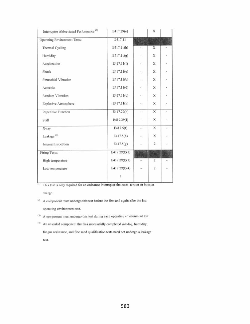
(xi) Potential consequences for other vehicles or systems of similar type and proposed operations.
(c) Response plan. A MIP must contain procedures to—
(1) Ensure the consequences of a launch accident, launch incident, reentry accident, reentry incident, or other mishap occurring in the conduct of an RLV mission are contained and minimized;
(2) Ensure data and physical evidence are preserved;
(3) Require the licensee to report and to cooperate with FAA and the National Transportation Safety Board investigations and designate one or more points of contact for the FAA or NTSB; and;
(4) Require the licensee to identify and adopt preventive measures for avoiding recurrence of the event.
(d) Investigation plan. A MIP shall contain—
(1) Procedures for investigating the cause of an event described in paragraph (c)(1) of this section;
(2) Procedures for reporting investigation results to the FAA;
(3) Delineated responsibilities, including reporting responsibilities, for personnel assigned to conduct investigations and for any unrelated entities retained by the licensee to conduct or participate in investigations.
(e) Emergency response plan. An ERP shall provide for—
(1) Notification to local officials in the event of an off-site or unplanned landing so that vehicle recovery can be conducted safely and effectively and with minimal risk to public safety. The plan must provide for the quick dissemination of up to date information to the public, and for doing so in advance of reentry or other landing on Earth to the extent practicable; and
(2) A public information dissemination plan for informing the potentially affected public, in laymen's terms and in advance of a planned reentry, of the estimated date, time and landing location for the reentry activity.
§ 431.47 Denial of safety approval.
The FAA notifies an applicant, in writing, if the FAA has denied safety approval for an RLV mission license application. The notice states the reasons for the FAA's
583

determination. The applicant may respond to the reasons for the determination and request reconsideration.
§§ 431.48-431.50 [Reserved]
Subpart D—Payload Reentry Review and Determination
§ 431.51 General.
(a) A payload reentry review is conducted to examine the policy and safety issues related to the proposed reentry of a payload, other than a U.S. Government payload or a payload whose reentry is subject to regulation by another Federal agency, to determine whether the FAA will approve reentry of the payload.
(b) A payload reentry review may be conducted as part of an RLV mission license application review or may be requested by a payload owner or operator in advance of or separate from an RLV mission license application.
(c) A payload reentry determination will be made part of the licensing record on which the FAA's licensing determination is based.
§ 431.53 Classes of payloads.
(a) The FAA may approve the return of a type or class of payload (for example, communications or microgravity/scientific satellites).
(b) The RLV mission licensee that will return a payload approved for reentry under this section, is responsible for providing current information in accordance with §431.57 regarding the payload proposed for reentry no later than 60 days before a scheduled RLV mission involving that payload.
§ 431.55 Payload reentry review.
(a) In conducting a payload reentry review to decide if the FAA should approve reentry of a payload, the FAA determines whether its reentry presents any issues that would adversely affect U.S. national security or foreign policy interests, would jeopardize public health and safety or the safety of property, or would not be consistent with international obligations of the United States.
(b) The FAA consults with the Department of Defense to determine whether reentry of a proposed payload presents any issues adversely affecting U.S. national security.
(c) The FAA consults with the Department of State to determine whether reentry of a proposed payload presents any issues adversely affecting U.S. foreign policy interests or international obligations.
584
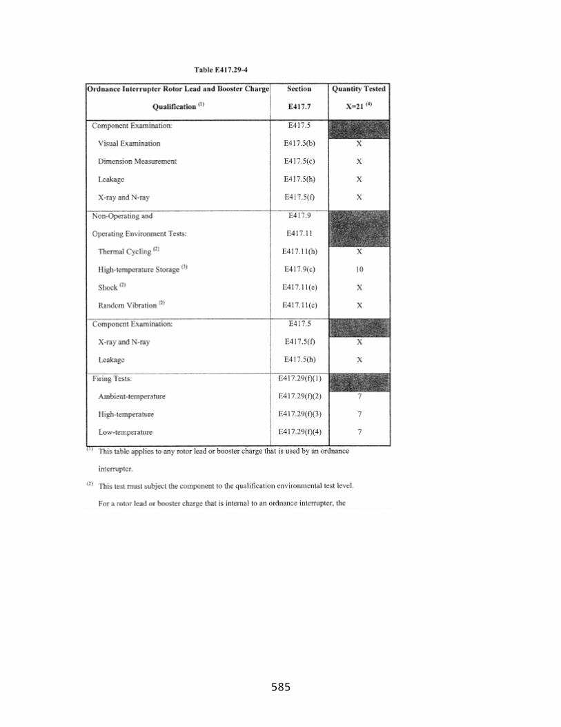
(d) The FAA consults with other Federal agencies, including the National Aeronautics and Space Administration, authorized to address issues identified under paragraph (a) of this section.
(e) The FAA advises a person requesting a payload reentry determination, in writing, of any issue raised during a payload reentry review that would impede the issuance of a favorable determination to reenter that payload. The person requesting a payload reentry review may respond, in writing, or revise its application.
§ 431.57 Information requirements for payload reentry review.
A person requesting reentry review of a particular payload or payload class must identify the following:
(a) Payload name or class and function;
(b) Physical characteristics, dimensions, and weight of the payload;
(c) Payload owner and operator, if different from the person requesting the payload reentry review;
(d) Type, amount, and container of hazardous materials, as defined in §401.5 of this chapter, and radioactive materials in the payload;
(e) Explosive potential of payload materials, alone and in combination with other materials found on the payload or RLV during reentry;
(f) Designated reentry site(s); and
(g) Method for securing the payload on the RLV.
§ 431.59 Issuance of payload reentry determination.
(a) The FAA issues a favorable payload reentry determination unless it determines that reentry of the proposed payload would adversely affect U.S. national security or foreign policy interests, would jeopardize public health and safety or the safety of property, or would not be consistent with international obligations of the United States. The FAA responds to any person who has requested a payload reentry review of its determination in writing. The notice states the reasons for the determination in the event of an unfavorable determination.
(b) Any person issued an unfavorable payload reentry determination may respond to the reasons for the determination and request reconsideration.
§ 431.61 Incorporation of payload reentry determination in license application.
585

A favorable payload reentry determination issued for a payload or class of payload may be included by an RLV mission license applicant as part of its application. Before the conduct of an RLV mission involving a payload approved for reentry, any change in information provided under §431.57 must be reported by the licensee in accordance with §413.17 of this chapter. The FAA determines whether a favorable payload reentry determination remains valid and may conduct an additional payload reentry review.
§§ 431.62-431.70 [Reserved]
Subpart E—Post-Licensing Requirements—Reusable Launch Vehicle Mission License Terms and Conditions
§ 431.71 Public safety responsibility.
(a) A licensee is responsible for ensuring the safe conduct of an RLV mission and for protecting public health and safety and the safety of property during the conduct of the mission.
(b) A licensee must conduct a licensed RLV mission and perform RLV safety procedures in accordance with representations made in its license application. A licensee's failure to perform safety procedures in accordance with the representations made in the license application or comply with any license condition is sufficient basis for the revocation of a license or other appropriate nforcement action.
§ 431.73 Continuing accuracy of license application; application for modification of license.
(a) A licensee is responsible for the continuing accuracy of representations contained in its application for the entire term of the license.
(b) After a license has been issued, a licensee must apply to the FAA for modification of the license if—
(1) The licensee proposes to conduct an RLV mission or perform a safety-critical operation in a manner not authorized by the license; or
(2) Any representation contained in the license application that is material to public health and safety or the safety of property is no longer accurate and complete or does not reflect the licensee's procedures governing the actual conduct of an RLV mission. A change is material to public health and safety or the safety of property if it alters or affects the—
(i) Mission rules, procedures, checklists, emergency plans, and contingency abort plans, if any, submitted in accordance with §431.39
586
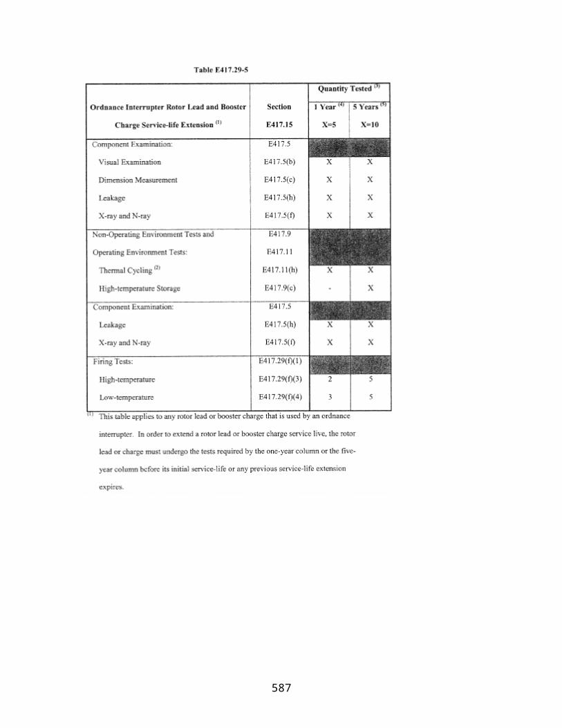
(ii) Class of payload;
(iii) Type of RLV;
(iv) Any safety-critical system;
(v) Type and container of the hazardous material carried by the vehicle;
(vi) Flight trajectory;
(vii) Launch site or reentry site or other landing location; or
(viii) Any safety system, policy, procedure, requirement, criteria, or standard.
(c) An application to modify an RLV mission license must be prepared and submitted in accordance with part 413 of this chapter. The licensee must indicate any part of its license or license application that would be changed or affected by a proposed modification.
(d) The FAA reviews determinations and approvals required by this chapter to determine whether they remain valid after submission of a proposed modification.
(e) Upon approval of a modification, the FAA issues either a written approval to the licensee or a license order amending the license if a stated term or condition of the license is changed, added, or deleted. An approval has the full force and effect of a license order and is part of the licensing record.
§ 431.75 Agreements.
(a) Launch and reentry site use agreements. Before conducting a licensed RLV mission using property and services of a Federal launch range or licensed launch or reentry site operator, a licensee or applicant shall enter into an agreement with the Federal launch range and/or licensed site operator that provides for access to and use of property and services required to support a licensed RLV mission or reentry and for public safety related operations and support. The agreement shall be in effect before any licensed RLV mission or reentry. A licensee shall comply with any requirements of the agreement that may affect public health and safety and the safety of property during the conduct of its licensed activity.
(b) Agreements for notices to mariners and airmen. Unless otherwise addressed in agreements between a licensed launch site operator and the U.S. Coast Guard and the FAA, respectively, a licensee authorized to conduct an RLV mission using a launch site or reentry site other than a Federal launch range shall complete the following:
(1) An agreement between the licensee and the local U.S. Coast Guard district to establish procedures for the issuance of a Notice to Mariners prior to a launch or reentry
587

and other measures as the Coast Guard deems necessary to protect public health and safety; and
(2) An agreement between the licensee and the FAA regional office having jurisdiction over the airspace through which a launch and reentry will take place, to establish procedures for the issuance of a Notice to Airmen prior to the conduct of a licensed launch or reentry and for closing of air routes during the respective launch and reentry windows and other measures deemed necessary by the FAA regional office in order to protect public health and safety.
§ 431.77 Records.
(a) Except as specified in paragraph (b) of this section, a licensee shall maintain for 3 years all records, data, and other material necessary to verify that a licensed RLV mission is conducted in accordance with representations contained in the licensee's application.
(b) In the event of a launch accident, reentry accident, launch incident or reentry incident, as defined in §401.5 of this chapter, a licensee shall preserve all records related to the event. Records must be retained until completion of any Federal investigation and the FAA advises the licensee that the records need not be retained. The licensee shall make all records required to be maintained under the regulations available to Federal officials for inspection and copying.
§ 431.79 Reusable launch vehicle mission reporting requirements.
(a) Not less than 60 days before each RLV mission conducted under a license, a licensee shall provide the FAA with the following information:
(1) Payload information in accordance with 14 CFR §415.59 of this chapter and §431.57; and
(2) Flight information, including the vehicle, launch site, planned launch and reentry flight path, and intended landing sites including contingency abort sites.
(3) Launch or reentry waivers, approved or pending, from a federal Federal range for at which the launch or reentry will take place, that are unique and may affect public safety.
(b) Not later than 15 days before each licensed RLV mission, a licensee must notify the FAA, in writing, of the time and date of the intended launch and reentry or other landing on Earth of the RLV and may utilize the FAA/U.S. Space Command Launch Notification Form, contained in part 415, Appendix A, of this subchapter for doing so.
(c) A licensee must report a launch accident, launch incident, reentry accident, reentry incident, or other mishap immediately to the FAA Washington Operations Center and provide a written preliminary report in the event of a launch accident, launch incident,
588

reentry accident, or reentry incident, in accordance with the mishap investigation and emergency response plan submitted as part of its license application under §431.45.
§ 431.81 Financial responsibility requirements.
A licensee under this part must comply with financial responsibility requirements specified in its license.
§ 431.83 Compliance monitoring.
A licensee shall allow access by, and cooperate with, Federal officers or employees or other individuals authorized by the FAA to observe any activities of the licensee, or of the licensee's contractors or subcontractors, associated with the conduct of a licensed RLV mission.
§ 431.85 Registration of space objects.
(a) To assist the U.S. Government in implementing Article IV of the 1975 Convention on Registration of Objects Launched into Outer Space, each licensee shall provide to the FAA the information required by paragraph (b) of this section for all objects placed in space by a licensed RLV mission, including an RLV and any components, except:
(1) Any object owned and registered by the U.S. Government; and
(2) Any object owned by a foreign entity.
(b) For each object that must be registered in accordance with this section, a licensee shall submit the following information not later than thirty (30) days following the conduct of a licensed RLV mission :
(1) The international designator of the space object(s);
(2) Date and location of the RLV mission initiation;
(3) General function of the space object; and
(4) Final orbital parameters, including:
(i) Nodal period;
(ii) Inclination;
(iii) Apogee; and
(iv) Perigee.
589
(c) A licensee shall notify the FAA when it removes an object that it has previously placed in space.
§§ 431.86-431.90 [Reserved]
Subpart F—Environmental Review
§ 431.91 General.
An applicant shall provide the FAA with sufficient information to analyze the environmental impacts associated with proposed operation of an RLV, including the impacts of anticipated activities to be performed at its reentry site. The information provided by an applicant must be sufficient to enable the FAA to comply with the requirements of the National Environmental Policy Act, 42 U.S.C. 4321 et seq., the Council on Environmental Quality Regulations for Implementing the Procedural Provisions of the National Environmental Policy Act, 40 CFR parts 1500–1508, and the FAA's Procedures for Considering Environmental Impacts, FAA Order 1050.1D. Copies of FAA Order 1050.1D may be obtained from the Office of Environment and Energy, AEE–300, Federal Aviation Administration, 800 Independence Avenue SW., Washington, DC 20591, (202) 267–3553. Copies of FAA Order 1050.1D may be inspected in the Rules Docket at the Federal Aviation Administration, Office of the Chief Counsel, AGC–200, Room 915G, 800 Independence Avenue SW., Washington, DC 20591 weekdays between 8:30 a.m. and 5:00 p.m.
§ 431.93 Environmental information.
An applicant shall submit environmental information concerning—
(a) A designated launch and reentry site, including contingency abort locations, if any, not covered by existing FAA or other Federal environmental documentation;
(b) A proposed new RLV with characteristics falling measurably outside the parameters of existing environmental documentation;
(c) A proposed reentry to an established reentry site involving an RLV with characteristics falling measurably outside the parameters of existing environmental impact statements covering that site;
(d) A proposed payload that may have significant environmental impacts in the event of a reentry accident; and
(e) Other factors as necessary to comply with the National Environmental Policy Act.
590

PART 433—LICENSE TO OPERATE A REENTRY SITE
Section Contents§ 433.1 General. § 433.3 Issuance of a license to operate a reentry site. § 433.5 Operational restrictions on a reentry site. § 433.7 Environmental. § 433.9 Environmental information.
Authority: 49 U.S.C. 70101–70121.
Source: Docket No. FAA–1999–5535, 65 FR 56665, Sept. 19, 2000, unless otherwise noted.
§ 433.1 General.
The FAA evaluates on an individual basis an applicant's proposal to operate a reentry site.
§ 433.3 Issuance of a license to operate a reentry site.
(a) The FAA issues a license to operate a reentry site when it determines that an applicant's operation of the reentry site does not jeopardize public health and safety, the safety of property, U.S. national security or foreign policy interests, or international obligations of the United States.
(b) A license to operate a reentry site authorizes a licensee to operate a reentry site in accordance with the representations contained in the licensee's application, subject to the licensee's compliance with terms and conditions contained in any license order accompanying the license.
§ 433.5 Operational restrictions on a reentry site.
A license to operate a reentry site authorizes the licensee to offer use of the site to support reentry of a reentry vehicle for which the three-sigma footprint of the vehicle upon reentry is wholly contained within the site.
§ 433.7 Environmental.
An applicant shall provide the FAA with information for the FAA to analyze the environmental impacts associated with proposed operation of a reentry site. The information provided by an applicant must be sufficient to enable the FAA to comply with the requirements of the National Environmental Policy Act, 42 U.S.C. 4321 et seq.
591
(NEPA), the Council on Environmental Quality Regulations for Implementing the Procedural Provisions of NEPA, 40 CFR Parts 1500–1508, and the FAA's Procedures for Consideration Environmental Impacts, FAA Order 1050.1D.
§ 433.9 Environmental information.
An applicant shall submit environmental information concerning a proposed reentry site not covered by existing environmental documentation for purposes of assessing reentry impacts.
592

PART 435—REENTRY OF A REENTRY VEHICLE OTHER THAN A REUSABLE LAUNCH VEHICLE (RLV)
Section Contents
Subpart A—General
§ 435.1 Scope. § 435.3 Types of reentry licenses. § 435.5 Policy and safety approvals. § 435.7 Payload reentry determination. § 435.8 Human space flight. § 435.9 Issuance of a reentry license. § 435.11 Additional license terms and conditions. § 435.13 Transfer of a reentry license. § 435.15 Rights not conferred by reentry license. §§ 435.16-431.20 [Reserved]
Subpart B—Policy Review and Approval for Reentry of a Reentry Vehicle
§ 435.21 General. § 435.23 Policy review requirements and procedures. §§ 435.24-435.30 [Reserved]
Subpart C—Safety Review and Approval for Reentry of a Reentry Vehicle
§ 435.31 General. § 435.33 Safety review requirements and procedures. § 435.35 Acceptable reentry risk for reentry of a reentry vehicle. §§ 435.36-435.40 [Reserved]
Subpart D—Payload Reentry Review and Determination
§ 435.41 General. § 435.43 Payload reentry review requirements and procedures. §§ 435.44-435.50 [Reserved]
Subpart E—Post-Licensing Requirements—Reentry License Terms and Conditions
§ 435.51 General. §§ 435.52-435.60 [Reserved]
Subpart F—Environmental Review
§ 435.61 General. §§ 435.62-435.70 [Reserved]
Authority: 49 U.S.C. 70101–70121.
593
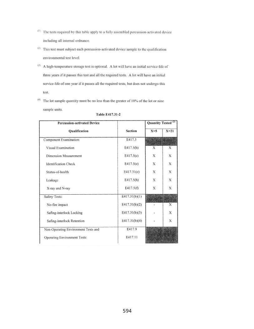
Source: Docket No. FAA–1999–5535, 65 FR 56665, Sept. 19, 2000, unless otherwise noted.
Subpart A—General
§ 435.1 Scope.
This part prescribes requirements for obtaining a license to reenter a reentry vehicle other than a reusable launch vehicle (RLV), and post-licensing requirements with which a licensee must comply to remain licensed. Requirements for preparing a license application are contained in part 413 of this subchapter.
§ 435.3 Types of reentry licenses.
(a) Reentry-specific license. A reentry-specific license authorizes a licensee to reenter one model or type of reentry vehicle, other than an RLV, to a reentry site or other location approved for the reentry. A reentry-specific license may authorize more than one reentry and identifies each reentry authorized under the license. A licensee's authorization to reenter terminates upon completion of all activities authorized by the license or the expiration date stated in the reentry license, whichever occurs first.
(b) Reentry-operator license. A reentry operator license authorizes a licensee to reenter any of a designated family of reentry vehicles, other than an RLV, within authorized parameters, including trajectories, transporting specified classes of payloads to any reentry site designated in the license. A reentry operator license is valid for a 2-year renewable term.
§ 435.5 Policy and safety approvals.
To obtain a reentry license, an applicant must obtain policy and safety approvals from the FAA. Requirements for obtaining these approvals are contained in subparts B and C of this part. Only a reentry license applicant may apply for the approvals, and may apply for either approval separately and in advance of submitting a complete license application, using the application procedures contained in part 413 of this subchapter.
§ 435.7 Payload reentry determination.
(a) A payload reentry determination is required to transport a payload to Earth on a reentry vehicle unless the proposed payload is exempt from payload review.
(b) A payload reentry determination made under a previous license application under this subchapter may satisfy the requirements of paragraph (a) of this section.
(c) The FAA conducts a review, as described in subpart D of this part, to make a payload reentry determination. Either a reentry license applicant or a payload owner or operator may request a review of the proposed payload using the application procedures contained
594
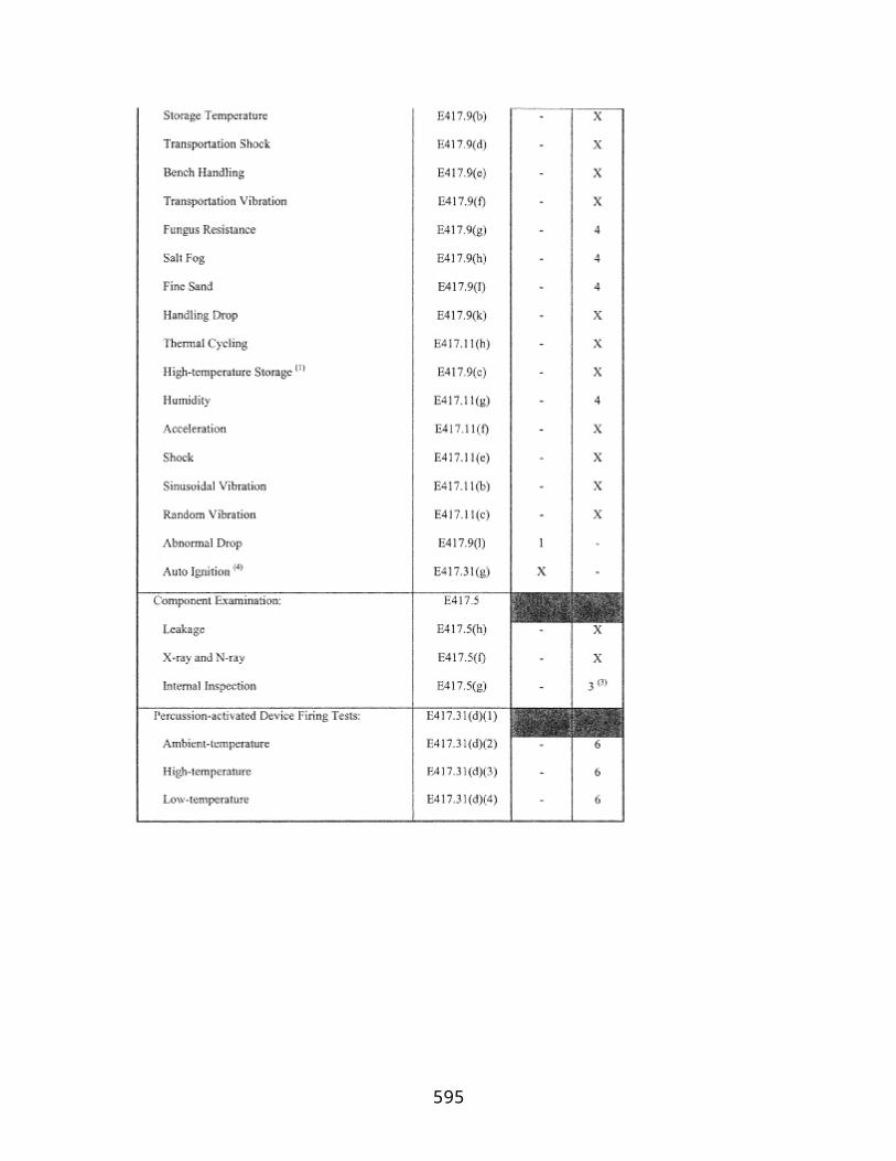
in part 413 of this subchapter. Upon receipt of an application, the FAA may conduct a payload reentry review independently of a reentry license application.
§ 435.8 Human space flight.
An applicant for a license to conduct a reentry with flight crew or a space flight participant on board the vehicle must demonstrate compliance with §§460.5, 460.7, 460.11, 460.13, 460.15, 460.17, 460.51 and 460.53 of this subchapter.
[Doc. No. FAA–2005–23449, 71 FR 75632, Dec. 15, 2006]
§ 435.9 Issuance of a reentry license.
(a) The FAA issues a reentry license to an applicant who has obtained all approvals and determinations required under this chapter for a reentry license.
(b) A reentry license authorizes a licensee to reenter a reentry vehicle and payload, if any, in accordance with the representations contained in the reentry licensee's application, subject to the licensee's compliance with terms and conditions contained in license orders accompanying the reentry license, including financial responsibility requirements.
§ 435.11 Additional license terms and conditions.
The FAA may amend a reentry license at any time by modifying or adding license terms and conditions to ensure compliance with 49 U.S.C. Subtitle IX, chapter 701, and applicable regulations.
§ 435.13 Transfer of a reentry license.
(a) Only the FAA may transfer a reentry license.
(b) An applicant for transfer of a reentry license shall submit a reentry license application in accordance with part 413 of this subchapter and satisfy the applicable requirements of this part. The FAA will transfer a reentry license to an applicant who has obtained all of the approvals and determinations required under this chapter for a reentry license. In conducting its reviews and issuing approvals and determinations, the FAA may incorporate any findings made part of the record to support the initial licensing determination. The FAA may modify a reentry license to reflect any changes necessary as a result of a reentry license transfer.
§ 435.15 Rights not conferred by reentry license.
Issuance of a reentry license does not relieve a licensee of its obligation to comply with requirements of law that may apply to its activities.
595

§§ 435.16-431.20 [Reserved]
Subpart B—Policy Review and Approval for Reentry of a Reentry Vehicle
§ 435.21 General.
The FAA issues a policy approval to a reentry license applicant upon completion of a favorable policy review. A policy approval is part of the licensing record on which the licensing determination is based.
§ 435.23 Policy review requirements and procedures.
Unless otherwise indicated in this subpart, regulations applicable to policy review and approval of the reentry of an RLV contained in part 431, subpart B of this subchapter shall apply to the policy review conducted for a license to reenter a reentry vehicle under this part.
§§ 435.24-435.30 [Reserved]
Subpart C—Safety Review and Approval for Reentry of a Reentry Vehicle
§ 435.31 General.
The FAA conducts a safety review to determine whether an applicant is capable of reentering a reentry vehicle and payload, if any, to a designated reentry site without jeopardizing public health and safety and the safety of property. A safety approval is part of the licensing record on which the licensing determination is based.
§ 435.33 Safety review requirements and procedures.
Unless otherwise stated in this subpart, regulations applicable to safety review and approval of the reentry of an RLV contained in part 431, subpart C of this subchapter shall apply to the safety review conducted for a license to reenter a reentry vehicle under this part.
§ 435.35 Acceptable reentry risk for reentry of a reentry vehicle.
To obtain safety approval for reentry, an applicant must demonstrate that risk for the proposed reentry, when assessed in combination with launch of the reentry vehicle, does not exceed acceptable risk for the conduct of an RLV mission as defined in paragraphs (a) and (b) of §431.35 of this subchapter.
596
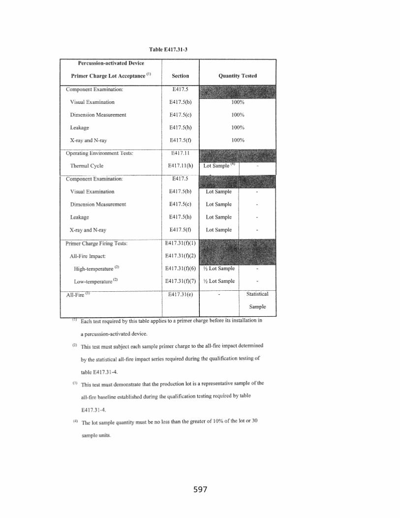
§§ 435.36-435.40 [Reserved]
Subpart D—Payload Reentry Review and Determination
§ 435.41 General.
The FAA conducts a payload reentry review to examine the policy and safety issues related to the proposed reentry of a payload, except a U.S. Government payload, to determine whether the FAA will approve the reentry of the payload.
§ 435.43 Payload reentry review requirements and procedures.
Unless otherwise indicated in this subpart, regulations contained in part 431, subpart D of this subchapter applicable to a payload reentry review and determination for reentering a payload using an RLV shall apply to the payload reentry review conducted for a license to reenter a reentry vehicle under this part.
§§ 435.44-435.50 [Reserved]
Subpart E—Post-Licensing Requirements—Reentry License Terms and Conditions
§ 435.51 General.
Unless otherwise indicated in this subpart, post-licensing requirements contained in part 431 subpart E, of this subchapter applicable to a license to reenter an RLV shall apply to a license issued under this part.
§§ 435.52-435.60 [Reserved]
Subpart F—Environmental Review
§ 435.61 General.
Unless otherwise indicated in this subpart, environmental review requirements contained in part 431 subpart F, applicable to a license to reenter an RLV shall apply to an application for a reentry license under this part.
§§ 435.62-435.70 [Reserved]
597

PART 437—EXPERIMENTAL PERMITS
Section Contents
Subpart A—General Information
§ 437.1 Scope and organization of this part. § 437.3 Definitions. § 437.5 Eligibility for an experimental permit. § 437.7 Scope of an experimental permit. § 437.9 Issuance of an experimental permit. § 437.11 Duration of an experimental permit. § 437.13 Additional experimental permit terms and conditions. § 437.15 Transfer of an experimental permit. § 437.17 Rights not conferred by an experimental permit.
Subpart B—Requirements to Obtain an Experimental Permit
§ 437.21 General.
Program Description§ 437.23 Program description.
Flight Test Plan§ 437.25 Flight test plan.
Operational Safety Documentation§ 437.27 Pre-flight and post-flight operations. § 437.29 Hazard analysis. § 437.31 Verification of operating area containment and key flight-safety event limitations. § 437.33 Landing and impact locations. § 437.35 Agreements. § 437.37 Tracking. § 437.39 Flight rules. § 437.41 Mishap response plan.
Subpart C—Safety Requirements
§ 437.51 Rest rules for vehicle safety operations personnel. § 437.53 Pre-flight and post-flight operations. § 437.55 Hazard analysis. § 437.57 Operating area containment. § 437.59 Key flight-safety event limitations. § 437.61 Landing and impact locations. § 437.63 Agreements with other entities involved in a launch or reentry. § 437.65 Collision avoidance analysis. § 437.67 Tracking a reusable suborbital rocket. § 437.69 Communications. § 437.71 Flight rules. § 437.73 Anomaly recording, reporting and implementation of corrective actions.
598

§ 437.75 Mishap reporting, responding, and investigating. § 437.77 Additional safety requirements.
Subpart D—Terms and Conditions of an Experimental Permit
§ 437.81 Public safety responsibility. § 437.83 Compliance with experimental permit. § 437.85 Allowable design changes; modification of an experimental permit. § 437.87 Records. § 437.89 Pre-flight reporting. § 437.91 For-hire prohibition. § 437.93 Compliance monitoring. § 437.95 Inspection of additional reusable suborbital rockets.
Authority: 49 U.S.C. 70101–70102.
Source: Docket No. FAA–2006–24197, 72 FR 17019, Apr. 6, 2007, unless otherwise noted.
Subpart A—General Information
§ 437.1 Scope and organization of this part.
(a) This part prescribes requirements for obtaining an experimental permit. It also prescribes post-permitting requirements with which a permittee must comply to maintain its permit. Part 413 of this subchapter contains procedures for applying for an experimental permit.
(b) Subpart A contains general information about an experimental permit. Subpart B contains requirements to obtain an experimental permit. Subpart C contains the safety requirements with which a permittee must comply while conducting permitted activities. Subpart D contains terms and conditions of an experimental permit.
§ 437.3 Definitions.
Anomaly means a problem that occurs during verification or operation of a system, subsystem, process, facility, or support equipment.
Envelope expansion means any portion of a flight where planned operations will subject a reusable suborbital rocket to the effects of altitude, velocity, acceleration, or burn duration that exceed a level or duration successfully verified during an earlier flight.
Exclusion area means an area, within an operating area, that a reusable suborbital rocket's instantaneous impact point may not traverse.
Key flight-safety event means a permitted flight activity that has an increased likelihood of causing a launch accident compared with other portions of flight.
599

Operating area means a three-dimensional region where permitted flights may take place.
Permitted vehicle means a reusable suborbital rocket operated by a launch or reentry operator under an experimental permit.
Reentry impact point means the location of a reusable suborbital rocket's instantaneous impact point during its unpowered exoatmospheric suborbital flight.
§ 437.5 Eligibility for an experimental permit.
The FAA will issue an experimental permit to a person to launch or reenter a reusable suborbital rocket only for—
(a) Research and development to test new design concepts, new equipment, or new operating techniques;
(b) A showing of compliance with requirements for obtaining a license under this subchapter; or
(c) Crew training before obtaining a license for a launch or reentry using the design of the rocket for which the permit would be issued.
§ 437.7 Scope of an experimental permit.
An experimental permit authorizes launch or reentry of a reusable suborbital rocket. The authorization includes pre- and post-flight ground operations as defined in this section.
(a) A pre-flight ground operation includes each operation that—
(1) Takes place at a U.S. launch site; and
(2) Meets the following criteria:
(i) Is closely proximate in time to flight,
(ii) Entails critical steps preparatory to initiating flight,
(iii) Is unique to space launch, and
(iv) Is inherently so hazardous as to warrant the FAA's regulatory oversight.
(b) A post-flight ground operation includes each operation necessary to return the reusable suborbital rocket to a safe condition after it lands or impacts.
§ 437.9 Issuance of an experimental permit.
600
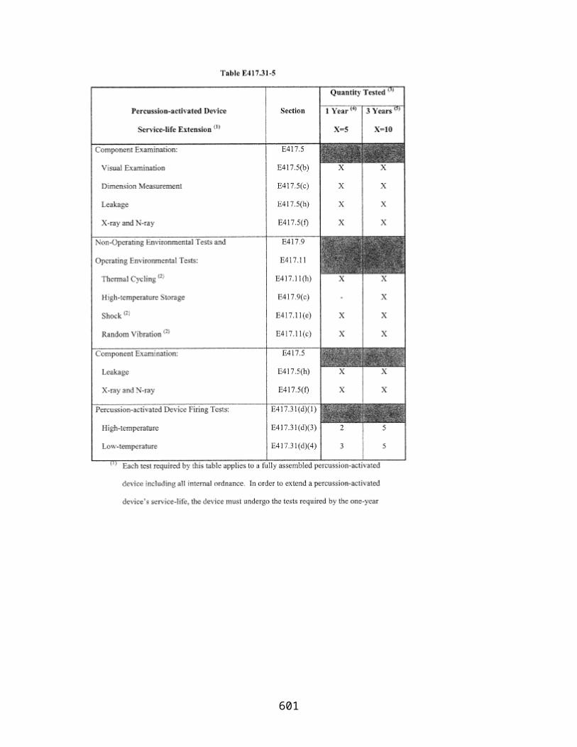
The FAA issues an experimental permit authorizing an unlimited number of launches or reentries for a suborbital rocket design for the uses described in §437.5.
§ 437.11 Duration of an experimental permit.
An experimental permit lasts for one year from the date it is issued. A permittee may apply to renew a permit yearly under part 413 of this subchapter.
§ 437.13 Additional experimental permit terms and conditions.
The FAA may modify an experimental permit at any time by modifying or adding permit terms and conditions to ensure compliance with 49 U.S.C. Subtitle IX, ch. 701.
§ 437.15 Transfer of an experimental permit.
An experimental permit is not transferable.
§ 437.17 Rights not conferred by an experimental permit.
Issuance of an experimental permit does not relieve a permittee of its obligation to comply with any requirement of law that applies to its activities.
Subpart B—Requirements to Obtain an Experimental Permit
§ 437.21 General.
To obtain an experimental permit an applicant must make the demonstrations and provide the information required by this section.
(a) This subpart. An applicant must provide a program description, a flight test plan, and operational safety documentation as required by this subpart.
(b) Other regulations —(1) Environmental. An applicant must provide enough information for the FAA to analyze the environmental impacts associated with proposed reusable suborbital rocket launches or reentries. The information provided by an applicant must be sufficient to enable the FAA to comply with the requirements of the National Environmental Policy Act, 42 U.S.C. 4321 et seq. , and the Council on Environmental Quality Regulations for Implementing the Procedural Provisions of the National Environmental Policy Act, 40 CFR parts 1500–1508.
(2) Financial responsibility. An applicant must provide the information required by part 3 of appendix A of part 440 for the FAA to conduct a maximum probable loss analysis.
(3) Human space flight. An applicant proposing launch or reentry with flight crew or a space flight participant on board a reusable suborbital rocket must demonstrate
601

compliance with §§460.5, 460.7, 460.11, 460.13, 460.15, 460.17, 460.51 and 460.53 of this subchapter.
(c) Use of a safety approval. If an applicant proposes to use any reusable suborbital rocket, safety system, process, service, or personnel for which the FAA has issued a safety approval under part 414 of this subchapter, the FAA will not reevaluate that safety element to the extent its use is within its approved envelope. As part of the application process, the FAA will evaluate the integration of that safety element into vehicle systems or operations.
(d) Inspection before issuing a permit. Before the FAA issues an experimental permit, an applicant must make each reusable suborbital rocket planned to be flown available to the FAA for inspection. The FAA will determine whether each reusable suborbital rocket is built as represented in the application.
(e) Other requirements. The FAA may require additional analyses, information, or agreements if necessary to protect public health and safety, safety of property, and national security and foreign policy interests of the United States.
Program Description
§ 437.23 Program description.
(a) An applicant must provide—
(1) Dimensioned three-view drawings or photographs of the reusable suborbital rocket; and
(2) Gross liftoff weight and thrust profile of the reusable suborbital rocket.
(b) An applicant must describe—
(1) All reusable suborbital rocket systems, including any structural, flight control, thermal, pneumatic, hydraulic, propulsion, electrical, environmental control, software and computing systems, avionics, and guidance systems used in the reusable suborbital rocket;
(2) The types and quantities of all propellants used in the reusable suborbital rocket;
(3) The types and quantities of any hazardous materials used in the reusable suborbital rocket;
(4) The purpose for which a reusable suborbital rocket is to be flown; and
(5) Each payload or payload class planned to be flown.
602
(c) An applicant must identify any foreign ownership of the applicant as follows:
(1) For a sole proprietorship or partnership, identify all foreign ownership,
(2) For a corporation, identify any foreign ownership interests of 10% or more, and
(3) For a joint venture, association, or other entity, identify any participating foreign entities.
Flight Test Plan
§ 437.25 Flight test plan.
An applicant must—
(a) Describe any flight test program, including estimated number of flights and key flight-safety events.
(b) Identify and describe the geographic coordinates of the boundaries of one or more proposed operating areas where it plans to perform its flights and that satisfy §437.57(b) of subpart C. The FAA may designate one or more exclusion areas in accordance with §437.57(c) of subpart C.
(c) For each operating area, provide the planned maximum altitude of the reusable suborbital rocket.
Operational Safety Documentation
§ 437.27 Pre-flight and post-flight operations.
An applicant must demonstrate how it will meet the requirements of §437.53(a) and (b) to establish a safety clear zone and verify that the public is outside that zone before and during any hazardous operation.
§ 437.29 Hazard analysis.
(a) An applicant must perform a hazard analysis that complies with §437.55(a).
(b) An applicant must provide to the FAA all the results of each step of the hazard analysis required by paragraph (a) of this section.
§ 437.31 Verification of operating area containment and key flight-safety event limitations.
603

(a) An applicant must identify, describe, and provide verification evidence of the methods and systems used to meet the requirement of §437.57(a) to contain its reusable suborbital rocket's instantaneous impact point within an operating area and outside any exclusion area. The description must include, at a minimum—
(1) Proof of physical limits on the ability of the reusable suborbital rocket to leave the operating area; or
(2) Abort procedures and other safety measures derived from a system safety engineering process.
(b) An applicant must identify, describe, and provide verification evidence of the methods and systems used to meet the requirements of §437.59 to conduct any key flight-safety event so that the reusable suborbital rocket's instantaneous impact point, including its expected dispersions, is over unpopulated or sparsely populated areas, and to conduct each reusable suborbital rocket flight so that the reentry impact point does not loiter over a populated area.
§ 437.33 Landing and impact locations.
An applicant must demonstrate that each location for nominal landing or any contingency abort landing of the reusable suborbital rocket, and each location for any nominal or contingency impact or landing of a component of that rocket, satisfies §437.61.
§ 437.35 Agreements.
An applicant must enter into the agreements required by §437.63, and provide a copy to the FAA.
§ 437.37 Tracking.
An applicant must identify and describe each method or system used to meet the tracking requirements of §437.67.
§ 437.39 Flight rules.
An applicant must provide flight rules as required by §437.71.
§ 437.41 Mishap response plan.
An applicant must provide a mishap response plan that meets the requirements of §437.75(b).
Subpart C—Safety Requirements
604
§ 437.51 Rest rules for vehicle safety operations personnel.
A permittee must ensure that all vehicle safety operations personnel adhere to the work and rest standards in this section during permitted activities.
(a) No vehicle safety operations personnel may work more than:
(1) 12 consecutive hours,
(2) 60 hours in the 7 days preceding a permitted activity, or
(3) 14 consecutive work days.
(b) All vehicle safety operations personnel must have at least 8 hours of rest after 12 hours of work.
(c) All vehicle safety operations personnel must receive a minimum 48-hour rest period after 5 consecutive days of 12-hour shifts.
§ 437.53 Pre-flight and post-flight operations.
A permittee must protect the public from adverse effects of hazardous operations and systems in preparing a reusable suborbital rocket for flight at a launch site in the United States and returning the reusable suborbital rocket and any support equipment to a safe condition after flight. At a minimum, a permittee must—
(a) Establish a safety clear zone that will contain the adverse effects of each operation involving a hazard; and
(b) Verify that the public is outside of the safety clear zone before and during any hazardous operation.
§ 437.55 Hazard analysis.
(a) A permittee must identify and characterize each of the hazards and assess the risk to public health and safety and the safety of property resulting from each permitted flight. This hazard analysis must—
(1) Identify and describe hazards, including but not limited to each of those that result from—
(i) Component, subsystem, or system failures or faults;
(ii) Software errors;
(iii) Environmental conditions;
605
(iv) Human errors;
(v) Design inadequacies; or
(vi) Procedural deficiencies.
(2) Determine the likelihood of occurrence and consequence for each hazard before risk elimination or mitigation.
(3) Ensure that the likelihood and consequence of each hazard meet the following criteria through risk elimination and mitigation measures:
(i) The likelihood of any hazardous condition that may cause death or serious injury to the public must be extremely remote.
(ii) The likelihood of any hazardous condition that may cause major property damage to the public, major safety-critical system damage or reduced capability, a significant reduction in safety margins, or a significant increase in crew workload must be remote.
(4) Identify and describe the risk elimination and mitigation measures required to satisfy paragraph (a)(3) of this section. The measures must include one or more of the following:
(i) Designing for minimum risk,
(ii) Incorporating safety devices,
(iii) Providing warning devices, or
(iv) Implementing procedures and training.
(5) Demonstrate that the risk elimination and mitigation measures achieve the risk levels of paragraph (a)(3)(i) of this section through validation and verification. Verification includes:
(i) Test data,
(ii) Inspection results, or
(iii) Analysis.
(b) A permittee must carry out the risk elimination and mitigation measures derived from its hazard analysis.
(c) A permittee must ensure the continued accuracy and validity of its hazard analysis throughout the term of its permit.
606

§ 437.57 Operating area containment.
(a) During each permitted flight, a permittee must contain its reusable suborbital rocket's instantaneous impact point within an operating area determined in accordance with paragraph (b) and outside any exclusion area defined by the FAA in accordance with paragraph (c) of this section.
(b) An operating area—
(1) Must be large enough to contain each planned trajectory and all expected vehicle dispersions;
(2) Must contain enough unpopulated or sparsely populated area to perform key flight-safety events as required by §437.59;
(3) May not contain or be adjacent to a densely populated area or large concentrations of members of the public; and
(4) May not contain or be adjacent to significant automobile traffic, railway traffic, or waterborne vessel traffic.
(c) The FAA may prohibit a reusable suborbital rocket's instantaneous impact point from traversing certain areas within an operating area by designating one or more areas as exclusion areas, if necessary to protect public health and safety, safety of property, or foreign policy or national security interests of the United States. An exclusion area may be confined to a specific phase of flight.
§ 437.59 Key flight-safety event limitations.
(a) A permittee must conduct any key flight-safety event so that the reusable suborbital rocket's instantaneous impact point, including its expected dispersion, is over an unpopulated or sparsely populated area. At a minimum, a key flight-safety event includes:
(1) Ignition of any primary rocket engine,
(2) Any staging event, or
(3) Any envelope expansion.
(b) A permittee must conduct each reusable suborbital rocket flight so that the reentry impact point does not loiter over a populated area.
§ 437.61 Landing and impact locations.
607
For a nominal or any contingency abort landing of a reusable suborbital rocket, or for any nominal or contingency impact or landing of a component of that rocket, a permittee must use a location that—
(a) Is big enough to contain an impact, including debris dispersion upon impact; and
(b) At the time of landing or impact, does not contain any members of the public.
§ 437.63 Agreements with other entities involved in a launch or reentry.
A permittee must comply with the agreements required by this section.
(a) A permittee must have an agreement in writing with a Federal launch range operator, a licensed launch site operator, or any other party that provides access to or use of property and services required to support the safe launch or reentry under a permit.
(b) Unless otherwise addressed in agreements with a licensed launch site operator or a Federal launch range, a permittee must have an agreement in writing with the following:
(1) For overflight of navigable water, a written agreement between the applicant and the local United States Coast Guard district to establish procedures for issuing a Notice to Mariners before a permitted flight, and
(2) A written agreement between the applicant and responsible Air Traffic Control authority having jurisdiction over the airspace through which a permitted launch or reentry is to take place, for measures necessary to ensure the safety of aircraft. The agreement must, at a minimum, demonstrate satisfaction of §§437.69(a) and 437.71(d).
§ 437.65 Collision avoidance analysis.
(a) For a permitted flight with a planned maximum altitude greater than 150 kilometers, a permittee must obtain a collision avoidance analysis from United States Strategic Command.
(b) The collision avoidance analysis must establish each period during which a permittee may not initiate flight to ensure that a permitted vehicle and any jettisoned components do not pass closer than 200 kilometers to a manned or mannable orbital object. A distance of less than 200 kilometers may be used if the distance provides an equivalent level of safety, and if the distance accounts for all uncertainties in the analysis.
§ 437.67 Tracking a reusable suborbital rocket.
A permittee must—
608

(a) During permitted flight, measure in real time the position and velocity of its reusable suborbital rocket; and
(b) Provide position and velocity data to the FAA for post-flight use.
§ 437.69 Communications.
(a) A permittee must be in communication with Air Traffic Control during all phases of flight.
(b) A permittee must record communications affecting the safety of the flight.
§ 437.71 Flight rules.
(a) Before initiating rocket-powered flight, a permittee must confirm that all systems and operations necessary to ensure that safety measures derived from §§437.55, 437.57, 437.59, 437.61, 437.63, 437.65, 437.67, and 437.69 are within acceptable limits.
(b) During all phases of flight, a permittee must—
(1) Follow flight rules that ensure compliance with §§437.55, 437.57, 437.59, and 437.61; and
(2) Abort the flight if it would endanger the public.
(c) A permittee may not operate a reusable suborbital rocket in a careless or reckless manner that would endanger any member of the public during any phase of flight.
(d) A permittee may not operate a reusable suborbital rocket in areas designated in a Notice to Airmen under §91.137, §91.138, §91.141, or §91.145 of this title, unless authorized by:
(1) Air Traffic Control; or
(2) A Flight Standards Certificate of Waiver or Authorization.
(e) For any phase of flight where a permittee operates a reusable suborbital rocket like an aircraft in the National Airspace System, a permittee must comply with the provisions of part 91 of this title specified in an experimental permit issued under this part.
§ 437.73 Anomaly recording, reporting and implementation of corrective actions.
(a) A permittee must record each anomaly that affects a safety-critical system, subsystem, process, facility, or support equipment.
609
(b) A permittee must identify all root causes of each anomaly, and implement all corrective actions for each anomaly.
(c) A permittee must report to the FAA any anomaly of any system that is necessary for complying with §§437.55(a)(3), 437.57, and 437.59, and must report the corrective action for each reported anomaly.
(d) A permittee must implement each corrective action before the next flight.
§ 437.75 Mishap reporting, responding, and investigating.
A permittee must report, respond to, and investigate mishaps that occur during permitted activities, in accordance with this section.
(a) Reporting requirements. A permittee must—
(1) Immediately notify the FAA Washington Operations Center if there is a launch or reentry accident or incident or a mishap that involves a fatality or serious injury, as defined in 49 CFR 830.2;
(2) Notify within 24 hours the FAA's Office of Commercial Space Transportation if there is a mishap that does not involve a fatality or serious injury, as defined in 49 CFR 830.2; and
(3) Submit within 5 days of the event a written preliminary report to the FAA's Office of Commercial Space Transportation if there is a launch or reentry accident or incident during a permitted flight. The report must identify the event as a launch or reentry accident or incident, and must include:
(i) The date and time of occurrence,
(ii) A description of the event and sequence of events leading to the launch or reentry accident, or launch or reentry incident, to the extent known,
(iii) The intended and actual location of launch or reentry, including landing or impact on Earth,
(iv) A description of any payload,
(v) The number and general description of any fatalities and injuries,
(vi) Property damage, if any, and an estimate of its value,
(vii) A description of any hazardous materials involved in the event, whether on the reusable suborbital rocket or on the ground,
610
(viii) Action taken by any person to contain the consequences of the event, and
(ix) Weather conditions at the time of the event.
(b) Response requirements. A permittee must—
(1) Immediately—
(i) Ensure the consequences of a mishap are contained and minimized; and
(ii) Ensure data and physical evidence are preserved.
(2) Report to and cooperate with FAA and National Transportation Safety Board (NTSB) investigations and designate one or more points of contact for the FAA or NTSB; and
(3) Identify and adopt preventive measures for avoiding a recurrence of the event.
(c) Investigation requirements. A permittee must—
(1) Investigate the root cause of an event described in paragraph (a) of this section;
(2) Report investigation results to the FAA upon completion; and
(3) Identify responsibilities, including reporting responsibilities, for personnel assigned to conduct investigations and for any unrelated persons that the permittee retains to conduct or participate in investigations.
§ 437.77 Additional safety requirements.
The FAA may impose additional safety requirements on an applicant or permittee proposing an activity with a hazard not otherwise addressed in this part. This may include a toxic hazard or the use of solid propellants. The FAA may also require the permittee to conduct additional analyses of the cause of any anomaly and corrective actions.
Subpart D—Terms and Conditions of an Experimental Permit
§ 437.81 Public safety responsibility.
A permittee must ensure that a launch or reentry conducted under an experimental permit is safe, and must protect public health and safety and the safety of property.
§ 437.83 Compliance with experimental permit.
A permittee must conduct any launch or reentry under an experimental permit in accordance with representations made in its permit application, with subparts C and D of this part, and with terms and conditions contained in the permit.
611

§ 437.85 Allowable design changes; modification of an experimental permit.
(a) The FAA will identify in the experimental permit the type of changes that the permittee may make to the reusable suborbital rocket design without invalidating the permit.
(b) Except for design changes made under paragraph (a) of this section, a permittee must ask the FAA to modify the experimental permit if—
(1) It proposes to conduct permitted activities in a manner not authorized by the permit; or
(2) Any representation in its permit application that is material to public health and safety or the safety of property is no longer accurate or complete.
(c) A permittee must prepare an application to modify an experimental permit and submit it in accordance with part 413 of this subchapter. If requested during the application process, the FAA may approve an alternate method for requesting permit modifications. The permittee must indicate any part of its permit that would be changed or affected by a proposed modification.
(d) When a permittee proposes a modification, the FAA reviews the determinations made on the experimental permit to decide whether they remain valid.
(e) When the FAA approves a modification, it issues the permittee either a written approval or a permit order modifying the permit if a stated term or condition of the permit is changed, added, or deleted. An approval has the full force and effect of a permit order and is part of the permit record.
§ 437.87 Records.
(a) Except as required by paragraph (b) of this section, a permittee must maintain for 3 years all records, data, and other material necessary to verify that a permittee conducted its launch or reentry in accordance with its permit.
(b) If there is a launch or reentry accident or incident, a permittee must preserve all records related to the event. A permittee must keep the records until after any Federal investigation and the FAA advises the permittee that it may dispose of them.
(c) A permittee must make all records that it must maintain under this section available to Federal officials for inspection and copying.
§ 437.89 Pre-flight reporting.
612

(a) Not later than 30 days before each flight or series of flights conducted under an experimental permit, a permittee must provide the FAA with the following information:
(1) Any payload to be flown, including any payload operations during the flight,
(2) When the flight or series of flights are planned,
(3) The operating area for each flight, and
(4) The planned maximum altitude for each flight.
(b) Not later than 15 days before each permitted flight planned to reach greater than 150 km altitude, a permittee must provide the FAA its planned trajectory for a collision avoidance analysis.
§ 437.91 For-hire prohibition.
No permittee may carry any property or human being for compensation or hire on a reusable suborbital rocket.
§ 437.93 Compliance monitoring.
A permittee must allow access by, and cooperate with, federal officers or employees or other individuals authorized by the FAA to observe any activities of the permittee, or of its contractors or subcontractors, associated with the conduct of permitted activities.
§ 437.95 Inspection of additional reusable suborbital rockets.
A permittee may launch or reenter additional reusable suborbital rockets of the same design under the permit after the FAA inspects each additional reusable suborbital rocket.
613

PART 440—FINANCIAL RESPONSIBILITY
Section Contents
Subpart A—Financial Responsibility for Licensed and Permitted Activities
§ 440.1 Scope of part. § 440.3 Definitions. § 440.5 General. § 440.7 Determination of maximum probable loss. § 440.9 Insurance requirements for licensed or permitted activities. § 440.11 Duration of coverage for licensed launch, including suborbital launch, or permitted activities; modifications.§ 440.12 Duration of coverage for licensed reentry; modifications. § 440.13 Standard conditions of insurance coverage. § 440.15 Demonstration of compliance. § 440.17 Reciprocal waiver of claims requirements. § 440.19 United States payment of excess third-party liability claims. Appendix A to Part 440—Information Requirements for Obtaining a Maximum Probable Loss Determination for Licensed or Permitted ActivitiesAppendix B to Part 440—Agreement for Waiver of Claims and Assumption of Responsibility for Licensed ActivitiesAppendix C to Part 440—Agreement for Waiver of Claims and Assumption of Responsibility for Permitted ActivitiesAppendix D to Part 440—Agreement for Waiver of Claims and Assumption of Responsibility for a Crew MemberAppendix E to Part 440—Agreement for Waiver of Claims and Assumption of Responsibility for a Space Flight Participant
Authority: 49 U.S.C. 70101–70119; 49 CFR 1.47.
Source: Docket No. FAA–2005–23449, 71 FR 75632, Dec. 15, 2006, unless otherwise noted.
Subpart A—Financial Responsibility for Licensed and Permitted Activities
§ 440.1 Scope of part.
This part establishes financial responsibility and allocation of risk requirements for any launch or reentry authorized by a license or permit issued under this subchapter.
§ 440.3 Definitions.
Except as otherwise provided in this section, any term used in this part and defined in 49 U.S.C. 70101–70121, or in §401.5 of this chapter shall have the meaning contained therein. For purposes of this part—
614

Bodily injury means physical injury, sickness, disease, disability, shock, mental anguish, or mental injury sustained by any person, including death.
Contractors and subcontractors means those entities that are involved at any level, directly or indirectly, in licensed or permitted activities, and includes suppliers of property and services, and the component manufacturers of a launch vehicle, reentry vehicle, or payload.
Customer means.
(1) Any person:
(i) Who procures launch or reentry services from a licensee or permittee;
(ii) With rights in the payload (or any part of the payload) to be launched or reentered by the licensee or permittee, including a conditional sale, lease, assignment, or transfer of rights;
(iii) Who has placed property on board the payload for launch, reentry, or payload services; or
(iv) To whom the customer has transferred its rights to the launch or reentry services.
(2) A space flight participant, for the purposes of this part, is not a customer.
Federal range facility means a U.S. Government-owned installation at which a launch or reentry takes place.
Financial responsibility means capable of satisfying a liability obligation as required by 49 U.S.C. Subtitle IX, chapter 701.
Government personnel means employees of the United States, its agencies, and its contractors and subcontractors, involved in launch or reentry services for an activity authorized by an FAA license or permit. Employees of the United States include members of the Armed Forces of the United States.
Hazardous operations means activities, processes, and procedures that, because of the nature of the equipment, facilities, personnel, environment involved or function being performed, may result in bodily injury or property damage.
Liability means a legal obligation to pay a claim for bodily injury or property damage resulting from a licensed or permitted activity.
License means an authorization the FAA issues under this subchapter to launch or reenter a launch or reentry vehicle.
615

Licensed activity means the launch of a launch vehicle or the reentry of a reentry vehicle conducted under a license the FAA issues.
Maximum probable loss (MPL) means the greatest dollar amount of loss for bodily injury or property damage that is reasonably expected to result from a licensed or permitted activity;
(1) Losses to third parties, excluding Government personnel and other launch or reentry participants' employees involved in licensed or permitted activities, that are reasonably expected to result from a licensed or permitted activity are those that have a probability of occurrence of no less than one in ten million.
(2) Losses to Government property and Government personnel involved in licensed or permitted activities that are reasonably expected to result from licensed or permitted activities are those that have a probability of occurrence of no less than one in one hundred thousand.
Permit means an authorization the FAA issues under this subchapter for the launch or reentry of a reusable suborbital rocket.
Permitted activity means the launch or reentry of a reusable suborbital rocket conducted under a permit issued by the FAA.
Property damage means partial or total destruction, impairment, or loss of tangible property, real or personal.
Regulations mean the Commercial Space Transportation Licensing Regulations codified at 14 CFR Ch. III.
Third party means
(1) Any person other than:
(i) The United States, any of its agencies, and its contractors and subcontractors involved in launch or reentry services for a licensed or permitted activity;
(ii) A licensee, permittee, and its contractors and subcontractors involved in launch or reentry services for a licensed or permitted activity;
(iii) A customer and its contractors and subcontractors involved in launch or reentry services for a licensed or permitted activity;
(iv) A member of a crew; and
(v) A space flight participant.
616

(2) Government personnel, as defined in this section, are third parties.
United States means the United States Government, including each of its agencies.
§ 440.5 General.
(a) No person may commence or conduct any launch or reentry activity that requires a license or permit unless that person has demonstrated compliance with the requirements of this part.
(b) The FAA will prescribe the amount of financial responsibility a licensee or permittee must obtain and any adjustments of the amount in a license or permit order issued concurrent with or subsequent to the issuance of a license or a permit.
(c) Demonstration of financial responsibility under this part shall not relieve a licensee of ultimate responsibility for liability, loss, or damage sustained by the United States resulting from a licensed activity, except to the extent that:
(1) Liability, loss, or damage sustained by the United States results from willful misconduct of the United States or its agents;
(2) Any covered claim of a third party for bodily injury or property damage arising out of any particular licensed activity exceeds the amount of financial responsibility required under §440.9(c) of this part and does not exceed $1,500,000,000 (as adjusted for inflation) above such amount, and are payable pursuant to 49 U.S.C. 70113 and §440.19 of this part. A claim of an employee of any entity listed in paragraphs (1)(ii) through (1)(iii) in the Third party definition in §440.3 of this part for bodily injury or property damage is not a covered claim;
(3) A covered claim for property loss or damage exceeds the amount of financial responsibility required under §440.9(e) of this part and does not result from willful misconduct of the licensee; or
(4) The licensee has no liability for covered claims by third parties for bodily injury or property damage arising out of any particular launch or reentry that exceeds $1,500,000,000 (as adjusted for inflation) above the amount of financial responsibility required under §440.9(c).
(d) Demonstration of financial responsibility under this part does not relieve a permittee of ultimate responsibility for liability, loss, or damage sustained by the United States resulting from a permitted activity, except to the extent that:
(1) Liability, loss, or damage sustained by the United States results from willful misconduct of the United States or its agents; or
617

(2) A covered claim for property loss or damage to the United States exceeds the amount of financial responsibility required under §440.9(e) and does not result from willful misconduct of the permittee.
(e) A licensee's or permittee's failure to comply with any requirement of this part may result in suspension or revocation of a license or permit, and subject the licensee or permittee to civil penalties as provided in part 405 of this chapter.
§ 440.7 Determination of maximum probable loss.
(a) The FAA will determine the maximum probable loss (MPL) from covered claims by a third party for bodily injury or property damage, and the United States, its agencies, and its contractors and subcontractors for covered property damage or loss, resulting from a permitted or licensed activity. The maximum probable loss determination forms the basis for financial responsibility requirements issued in a license or permit order.
(b) The FAA issues its determination of maximum probable loss no later than ninety days after a licensee or permittee has requested a determination and submitted all information required by the FAA to make the determination. The FAA will consult with Federal agencies that are involved in, or whose personnel or property are exposed to risk of damage or loss as a result of, a licensed or permitted activity before issuing a license or permit order prescribing financial responsibility requirements, and shall notify the licensee, or permittee, if interagency consultation may delay issuance of the MPL determination.
(c) Appendix A of this part contains information requirements for obtaining a maximum probable loss determination. Any person requesting a determination of maximum probable loss must submit the information required by Appendix A, unless the FAA has waived a requirement. In lieu of submitting required information, a person requesting a maximum probable loss determination may designate and certify certain information previously submitted for a prior determination as complete, valid, and equally applicable to its current request. The requester is responsible for the continuing accuracy and completeness of information submitted under this part and must promptly report any changes in writing.
(d) The FAA will amend a determination of maximum probable loss required under this section at any time prior to completion of licensed or permitted activities as warranted by supplementary information provided to or obtained by the FAA after the MPL determination is issued. Any change in financial responsibility requirements as a result of an amended MPL determination shall be set forth in a license or permit order.
(e) The FAA may make a determination of maximum probable loss at any time other than as set forth in paragraph (b) of this section upon request by any person.
§ 440.9 Insurance requirements for licensed or permitted activities.
618

(a) As a condition of each license or permit, a licensee or permittee must comply with all insurance requirements of this section and of a license or permit issued by the FAA, or otherwise demonstrate the required amount of financial responsibility.
(b) A licensee or permittee must obtain and maintain in effect a policy or policies of liability insurance, in an amount determined by the FAA under paragraph (c) of this section, that protects the following persons as additional insureds to the extent of their respective potential liabilities against covered claims by a third party for bodily injury or property damage resulting from a licensed or permitted activity:
(1) The licensee or permittee, its customer, and their respective contractors and subcontractors, and the employees of each, involved in a licensed or permitted activity;
(2) The United States, its agencies, and its contractors and subcontractors involved in a licensed or permitted activity; and
(3) Government personnel.
(c) The FAA will prescribe for each licensee or permittee the amount of insurance required to compensate the total of covered third-party claims for bodily injury or property damage resulting from a licensed or permitted activity in connection with any particular launch or reentry. A covered third-party claim includes a claim by the United States, its agencies, and its contractors and subcontractors for damage or loss to property other than property for which insurance is required under paragraph (d) of this section. The amount of insurance required is based upon the FAA's determination of maximum probable loss; however, it will not exceed the lesser of:
(1) $500 million; or
(2) The maximum liability insurance available on the world market at a reasonable cost, as determined by the FAA.
(d) The licensee or permittee must obtain and maintain in effect a policy or policies of insurance, in an amount determined by the FAA under paragraph (e) of this section, that covers claims by the United States, its agencies, and its contractors and subcontractors involved in a licensed or permitted activity for property damage or loss resulting from a licensed or permitted activity. Property covered by this insurance must include all property owned, leased, or occupied by, or within the care, custody, or control of, the United States and its agencies, and its contractors and subcontractors involved in a licensed or permitted activity, at a Federal range facility. Insurance must protect the United States and its agencies, and its contractors and subcontractors involved in a licensed or permitted activity.
(e) The FAA will prescribe for each licensee or permittee the amount of insurance required to compensate claims for property damage under paragraph (d) of this section resulting from a licensed or permitted activity in connection with any particular launch or
619
reentry. The amount of insurance is based upon a determination of maximum probable loss; however, it will not exceed the lesser of:
(1) $100 million; or
(2) The maximum available on the world market at a reasonable cost, as determined by the FAA.
(f) In lieu of a policy of insurance, a licensee or permittee may demonstrate financial responsibility in another manner meeting the terms and conditions for insurance of this part. The licensee or permittee must describe in detail the method proposed for demonstrating financial responsibility and how it ensures that the licensee or permittee is able to cover claims as required under this part.
§ 440.11 Duration of coverage for licensed launch, including suborbital launch, or permitted activities; modifications.
(a) Insurance coverage required under §440.9, or other form of financial responsibility, shall attach when a licensed launch or permitted activity starts, and remain in full force and effect as follows:
(1) Until completion of licensed launch or permitted activities at a launch or reentry site; and
(2) For orbital launch, until the later of—
(i) Thirty days following payload separation, or attempted payload separation in the event of a payload separation anomaly; or
(ii) Thirty days from ignition of the launch vehicle.
(3) For a suborbital launch, until the later of—
(i) Motor impact and payload recovery; or
(ii) The FAA's determination that risk to third parties and Government property as a result of licensed launch or permitted activities is sufficiently small that financial responsibility is no longer necessary. That determination is made through the risk analysis conducted before the launch to determine MPL and specified in a license or permit order.
(b) Financial responsibility required under this part may not be replaced, canceled, changed, withdrawn, or in any way modified to reduce the limits of liability or the extent of coverage, nor expire by its own terms, prior to the time specified in a license or permit order, unless the FAA is notified at least 30 days in advance and expressly approves the modification.
620

§ 440.12 Duration of coverage for licensed reentry; modifications.
(a) For reentry, insurance coverage required under §440.9, or other form of financial responsibility, shall attach upon commencement of licensed reentry, and remain in full force and effect as follows:
(1) For ground operations, until completion of licensed reentry at the reentry site; and
(2) For other licensed reentry activities, 30 days from initiation of reentry flight; however, in the event of an abort that results in the reentry vehicle remaining on orbit, insurance shall remain in place until the FAA's determination that risk to third parties and Government property as a result of licensed reentry is sufficiently small that financial responsibility is no longer necessary, as determined by the FAA through the risk analysis conducted to determine MPL and specified in a license order.
(b) Financial responsibility required under this part may not be replaced, canceled, changed, withdrawn, or in any way modified to reduce the limits of liability or the extent of coverage, nor expire by its own terms, prior to the time specified in a license order, unless the FAA is notified at least 30 days in advance and expressly approves the modification.
§ 440.13 Standard conditions of insurance coverage.
(a) Insurance obtained under §440.9 must comply with each of the following terms and conditions of coverage:
(1) Bankruptcy or insolvency of an insured, including any additional insured, shall not relieve an insurer of any of its obligations under any policy.
(2) Policy limits shall apply separately to each occurrence and, for each occurrence to the total of claims arising out of a licensed or permitted activity in connection with any particular launch or reentry.
(3) Except as provided in this section, each policy must pay claims from the first dollar of loss, without regard to any deductible, to the limits of the policy. A licensee or permittee may obtain a policy containing a deductible amount if the amount of the deductible is placed in an escrow account or otherwise demonstrated to be unobligated, unencumbered funds of the licensee or permittee, available to compensate claims at any time claims may arise.
(4) No policy may be invalidated by any action or inaction of the licensee or permittee or any additional insured, even by nonpayment by the licensee or permittee of the policy premium, and each policy must insure the licensee or permittee and each additional insured regardless of any breach or violation of any warranties, declarations, or conditions contained in the policies by the licensee or permittee or any additional insured
621

(other than a breach or violation by the licensee, permittee or an additional insured, and then only as against that licensee, permittee or additional insured).
(5) Each exclusion from coverage must be specified.
(6) Insurance shall be primary without right of contribution from any other insurance that is carried by the licensee or permittee or any additional insured.
(7) Each policy must expressly provide that all of its provisions, except the policy limits, operate in the same manner as if there were a separate policy with and covering the licensee or permittee and each additional insured.
(8) Each policy must be placed with an insurer of recognized reputation and responsibility that either:
(i) Is licensed to do business in any State, territory, possession of the United States, or the District of Columbia; or
(ii) Includes in each of its policies or insurance obtained under this part a contract clause in which the insurer agrees to submit to the jurisdiction of a court of competent jurisdiction within the United States and designates an authorized agent within the United States for service of legal process on the insurer.
(9) Except as to claims resulting from the willful misconduct of the United States or any of its agents, the insurer shall waive any and all rights of subrogation against each of the parties protected by required insurance.
(b) [Reserved]
§ 440.15 Demonstration of compliance.
(a) A licensee or permittee must submit to the FAA evidence of financial responsibility and compliance with allocation of risk requirements under this part, as follows, unless a license or permit order specifies otherwise due to the proximity of the intended date for commencement of licensed or permitted activities:
(1) All reciprocal waiver of claims agreements required under §440.17(c) must be submitted at least 30 days before the start of any licensed or permitted activity involving a customer, crew member, or space flight participant;
(2) Evidence of insurance must be submitted at least 30 days before commencement of any licensed launch or permitted activity, and for licensed reentry no less than 30 days before commencement of launch activities involving the reentry licensee;
622

(3) Evidence of financial responsibility in a form other than insurance, as provided under §440.9(f), must be submitted at least 60 days before commencement of a licensed or permitted activity; and
(4) Evidence of renewal of insurance or other form of financial responsibility must be submitted at least 30 days in advance of its expiration date.
(b) Upon a complete demonstration of compliance with financial responsibility and allocation of risk requirements under this part, the requirements of this part shall preempt each and any provision in any agreement between the licensee or permittee and an agency of the United States governing access to or use of United States launch or reentry property or launch or reentry services for a licensed or permitted activity which addresses financial responsibility, allocation of risk and related matters covered by 49 U.S.C. 70112, 70113.
(c) A licensee or permittee must demonstrate compliance as follows:
(1) The licensee or permittee must provide proof of the existence of the insurance required by §440.9 by:
(i) Certifying to the FAA that it has obtained insurance in compliance with the requirements of this part and any applicable license or permit order;
(ii) Filing with the FAA one or more certificates of insurance evidencing insurance coverage by one or more insurers under a currently effective and properly endorsed policy or policies of insurance, applicable to a licensed or permitted activity, on terms and conditions and in amounts prescribed under this part, and specifying policy exclusions;
(iii) In the event of any policy exclusions or limitations of coverage that may be considered usual under §440.19(c), or for purposes of implementing the Government's waiver of claims for property damage under 49 U.S.C. 70112(b)(2), certifying that insurance covering the excluded risks is not commercially available at reasonable cost; and
(iv) Submitting to the FAA, for signature by the Department on behalf of the United States Government, the waiver of claims and assumption of responsibility agreement required by §440.17(c), executed by the licensee or permittee and its customer.
(v) Submitting to the FAA, for signature by the Department on behalf of the United States Government, an agreement to waive claims and assume responsibility required by §440.17(e), executed by each space flight participant.
(vi) Submitting to the FAA, for signature by the Department on behalf of the United States Government, an agreement to waive claims and assume responsibility required by §440.17(f), executed by each member of the crew.
623
(2) Any certification required by this section must be signed by a duly authorized officer of the licensee or permittee.
(d) Each certificate of insurance required by paragraph (c)(1)(ii) of this section must be signed by the insurer issuing the policy and accompanied by an opinion of the insurance broker that the insurance obtained by the licensee or permittee complies with all the requirements for insurance of this part and any applicable license or permit order.
(e) The licensee or permittee must maintain, and make available for inspection by the FAA upon request, all required policies of insurance and other documents necessary to demonstrate compliance with this part.
(f) In the event the licensee or permittee demonstrates financial responsibility using means other than insurance, as provided under §440.9(f), the licensee or permittee must provide proof that it has met the requirements of this part and of a FAA issued license or permit order.
§ 440.17 Reciprocal waiver of claims requirements.
(a) As a condition of each license or permit, the licensee or permittee must comply with the reciprocal waiver of claims requirements of this section.
(b) The licensee or permittee shall implement a reciprocal waiver of claims with each of its contractors and subcontractors, each customer and each of the customer's contractors and subcontractors, under which each party waives and releases claims against all the other parties to the waiver and agrees to assume financial responsibility for property damage it sustains and for bodily injury or property damage sustained by its own employees, and to hold harmless and indemnify each other from bodily injury or property damage sustained by its employees, resulting from a licensed or permitted activity, regardless of fault.
(c) For each licensed or permitted activity in which the U.S. Government, any agency, or its contractors and subcontractors is involved or where property insurance is required under §440.9(d), the Federal Aviation Administration of the Department of Transportation, the licensee or permittee, and its customer shall enter into a three-party reciprocal waiver of claims agreement. The three-party reciprocal waiver of claims shall be in the form set forth in Appendix B of this part, for licensed activity, or Appendix C of this part, for permitted activity, of this part or in a form that satisfies the requirements.
(d) The licensee or permittee, its customer, and the Federal Aviation Administration of the Department of Transportation on behalf of the United States and its agencies but only to the extent provided in legislation, must agree in any waiver of claims agreement required under this part to indemnify another party to the agreement from claims by the indemnifying party's contractors and subcontractors arising out of the indemnifying party's failure to implement properly the waiver requirement.
624

(e) For each licensed or permitted activity in which the U.S. Government, any of its agencies, or its contractors and subcontractors are involved, the Federal Aviation Administration of the Department of Transportation and each space flight participant shall enter into or have in place a reciprocal waiver of claims agreement in the form of the agreement in Appendix E of this part or that satisfies its requirements.
(f) For each licensed or permitted activity in which the U.S. Government, any of its agencies, or its contractors and subcontractors is involved, the Federal Aviation Administration of the Department of Transportation and each crew member shall enter into or have in place a reciprocal waiver of claims agreement in the form of the agreement in Appendix D of this part or that satisfies its requirements.
§ 440.19 United States payment of excess third-party liability claims.
(a) The United States pays successful covered claims (including reasonable expenses of litigation or settlement) of a third party against a licensee, a customer, and the contractors and subcontractors of the licensee and the customer, and the employees of each involved in licensed activities, and the contractors and subcontractors of the United States and its agencies, and their employees, involved in licensed activities to the extent provided in an appropriation law or other legislative authority providing for payment of claims in accordance with 49 U.S.C. 70113, and to the extent the total amount of such covered claims arising out of any particular launch or reentry:
(1) Exceeds the amount of insurance required under §440.9(b); and
(2) Is not more than $1,500,000,000 (as adjusted for inflation occurring after January 1, 1989) above that amount.
(b) Payment by the United States under paragraph (a) of this section shall not be made for any part of such claims for which bodily injury or property damage results from willful misconduct by the party seeking payment.
(c) The United States shall provide for payment of claims by third parties for bodily injury or property damage that are payable under 49 U.S.C. 70113 and not covered by required insurance under §440.9(b), without regard to the limitation under paragraph (a)(1) of this section, because of an insurance policy exclusion that is usual. A policy exclusion is considered usual only if insurance covering the excluded risk is not commercially available at reasonable rates. The licensee must submit a certification in accordance with §440.15(c)(1)(iii) of this part for the United States to cover the claims.
(d) Upon the expiration of the policy period prescribed in accordance with §440.11(a), the United States shall provide for payment of claims that are payable under 49 U.S.C. 70113 from the first dollar of loss up to $1,500,000,000 (as adjusted for inflation occurring after January 1, 1989).
625

(e) Payment by the United States of excess third-party claims under 49 U.S.C. 70113 shall be subject to:
(1) Prompt notice by the licensee to the FAA that the total amount of claims arising out of licensed activities exceeds, or is likely to exceed, the required amount of financial responsibility. For each claim, the notice must specify the nature, cause, and amount of the claim or lawsuit associated with the claim, and the party or parties who may otherwise be liable for payment of the claim;
(2) Participation or assistance in the defense of the claim or lawsuit by the United States, at its election;
(3) Approval by the FAA of any settlement, or part of a settlement, to be paid by the United States; and
(4) Approval by Congress of a compensation plan prepared by the FAA and submitted by the President.
(f) The FAA will:
(1) Prepare a compensation plan outlining the total amount of claims and meeting the requirements set forth in 49 U.S.C. 70113;
(2) Recommend sources of funds to pay the claims; and
(3) Propose legislation as required to implement the plan.
(g) The FAA may withhold payment of a claim if it finds that the amount is unreasonable, unless it is the final order of a court that has jurisdiction over the matter.
626

Appendix A to Part 440—Information Requirements for Obtaining a Maximum Probable Loss Determination for Licensed or Permitted Activities
Any person requesting a maximum probable loss determination shall submit the following information to the FAA, unless the FAA has waived a particular information requirement under 14 CFR 440.7(c):
Part 1: Information Requirements for Licensed Launch, Including Suborbital Launch
I. General Information
A. Mission description.
1. A description of mission parameters, including:
a. Launch trajectory;
b. Orbital inclination; and
c. Orbit altitudes (apogee and perigee).
2. Flight sequence.
3. Staging events and the time for each event.
4. Impact locations.
5. Identification of the launch site facility, including the launch complex on the site, planned date of launch, and launch windows.
6. If the applicant has previously been issued a license or permit to conduct activities using the same vehicle from the same launch site, a description of any differences planned in the conduct of proposed activities.
B. Launch vehicle description.
1. General description of the launch vehicle and its stages, including dimensions.
2. Description of major systems, including safety systems.
3. Description of rocket motors and type of fuel used.
4. Identification of all propellants to be used and their hazard classification under the Hazardous Materials Table, 49 CFR 172.101.
627

5. Description of hazardous components.
C. Payload.
1. General description of the payload, including type (e.g., telecommunications, remote sensing), propellants, and hazardous components or materials, such as toxic or radioactive substances.
D. Flight safety system.
1. Identification of any flight safety system on the vehicle, including a description of operations and component location on the vehicle.
II. Pre-Flight Processing Operations
A. General description of pre-flight operations including vehicle processing consisting of an operational flow diagram showing the overall sequence and location of operations, commencing with arrival of vehicle components at the launch site facility through final safety checks and countdown sequence, and designation of hazardous operations, as defined in 14 CFR 440.3. For purposes of these information requirements, payload processing, as opposed to integration, is not a hazardous operation.
B. For each hazardous operation, including but not limited to fueling, solid rocket motor build-up, ordnance installation, ordnance checkout, movement of hazardous materials, and payload integration:
1. Identification of location where each operation will be performed, including each building or facility identified by name or number.
2. Identification of facilities adjacent to the location where each operation will be performed and therefore exposed to risk, identified by name or number.
3. Maximum number of Government personnel and individuals not involved in licensed activities who may be exposed to risk during each operation. For Government personnel, identification of his or her employer.
4. Identification of launch site policies or requirements applicable to the conduct of operations.
III. Flight Operations
A. Identification of launch site facilities exposed to risk during licensed flight.
B. Identification of accident failure scenarios, probability assessments for each, and estimation of risks to Government personnel, individuals not involved in licensed activities, and Government property, due to property damage or bodily injury. The
628

estimation of risks for each scenario shall take into account the number of such individuals at risk as a result of lift-off and flight of a launch vehicle (on-range, off-range, and down-range) and specific, unique facilities exposed to risk. Scenarios shall cover the range of launch trajectories, inclinations and orbits for which authorization is sought in the license application.
C. On-orbit risk analysis assessing risks posed by a launch vehicle to operational satellites.
D. Reentry risk analysis assessing risks to Government personnel and individuals not involved in licensed activities as a result of reentering debris or reentry of the launch vehicle or its components.
E. Trajectory data as follows: Nominal and 3-sigma lateral trajectory data in x, y, z and x (dot), y (dot), z (dot) coordinates in one-second intervals, data to be pad-centered with x being along the initial launch azimuth and continuing through impact for suborbital flights, and continuing through orbital insertion or the end of powered flight for orbital flights.
F. Tumble-turn data for guided vehicles only, as follows: For vehicles with gimbaled nozzles, tumble turn data with zeta angles and velocity magnitudes stated. A separate table is required for each combination of fail times (every two to four seconds), and significant nozzle angles (two or more small angles, generally between one and five degrees).
G. Identification of debris lethal areas and the projected number and ballistic coefficient of fragments expected to result from flight termination, initiated either by command or self-destruct mechanism, for lift-off, land overflight, and reentry.
IV. Post-Flight Processing Operations
A. General description of post-flight ground operations including overall sequence and location of operations for removal of vehicle components and processing equipment from the launch site facility and for handling of hazardous materials, and designation of hazardous operations.
B. Identification of all facilities used in conducting post-flight processing operations.
C. For each hazardous operation:
1. Identification of location where each operation is performed, including each building or facility identified by name or number.
2. Identification of facilities adjacent to location where each operation is performed and exposed to risk, identified by name or number.
629

3. Maximum number of Government personnel and individuals not involved in licensed launch activities that may be exposed to risk during each operation. For Government personnel, identification of his or her employer.
4. Identification of launch site facility policies or requirements applicable to the conduct of operations.
Part 2: Information Requirements for Licensed Reentry
I. General Information
A. Reentry mission description.
1. A description of mission parameters, including:
a. Orbital inclination; and
b. Orbit altitudes (apogee and perigee).
c. Reentry trajectories.
2. Reentry flight sequences.
3. Reentry initiation events and the time for each event.
4. Nominal landing location, alternative landing sites and contingency abort sites.
5. Identification of landing facilities, (planned date of reentry), and reentry windows.
6. If the applicant has previously been issued a license or permit to conduct reentry activities using the same reentry vehicle to the same reentry site facility, a description of any differences planned in the conduct of proposed activities.
B. Reentry vehicle description.
1. General description of the reentry vehicle, including dimensions.
2. Description of major systems, including safety systems.
3. Description of propulsion system (reentry initiation system) and type of fuel used.
4. Identification of all propellants to be used and their hazard classification under the Hazardous Materials Table, 49 CFR 172.101.
5. Description of hazardous components.
630

C. Payload.
1. General description of any payload, including type (e.g., telecommunications, remote sensing), propellants, and hazardous components or materials, such as toxic or radioactive substances.
D. Flight Safety System.
1. Identification of any flight safety system on the reentry vehicle, including a description of operations and component location on the vehicle.
II. Flight Operations
A. Identification of reentry site facilities exposed to risk during vehicle reentry and landing.
B. Identification of accident failure scenarios, probability assessments for each, and estimation of risks to Government personnel, individuals not involved in licensed reentry, and Government property, due to property damage or bodily injury. The estimation of risks for each scenario shall take into account the number of such individuals at risk as a result of reentry (flight) and landing of a reentry vehicle (on-range, off-range, and down-range) and specific, unique facilities exposed to risk. Scenarios shall cover the range of reentry trajectories for which authorization is sought.
C. On-orbit risk analysis assessing risks posed by a reentry vehicle to operational satellites during reentry.
D. Reentry risk analysis assessing risks to Government personnel and individuals not involved in licensed activities as a result of inadvertent or random reentry of the launch vehicle or its components.
E. Nominal and 3-sigma dispersed trajectories in one-second intervals, from reentry initiation through landing or impact. (Coordinate system will be specified on a case-by-case basis)
F. Three-sigma landing or impact dispersion area in downrange (±) and crossrange
(±) measured from the nominal and contingency landing or impact target. The applicant is responsible for including all significant landing or impact dispersion constituents in the computations of landing or impact dispersion areas. The dispersion constituents should include, but not be limited to: Variation in orbital position and velocity at the reentry initiation time; variation in re-entry initiation time offsets, either early or late; variation in the bodies' ballistic coefficient; position and velocity variation due to winds; and variations in re-entry retro-maneuvers.
631

G. Malfunction turn data (tumble, trim) for guided (controllable) vehicles. The malfunction turn data shall include the total angle turned by the velocity vector versus turn duration time at one second intervals; the magnitude of the velocity vector versus turn duration time at one second intervals; and an indication on the data where the re-entry body will impact the Earth, or breakup due to aerodynamic loads. A malfunction turn data set is required for each malfunction time. Malfunction turn start times shall not exceed four-second intervals along the trajectory.
H. Identification of debris casualty areas and the projected number and ballistic coefficient of fragments expected to result from each failure mode during reentry, including random reentry.
III. Post-Flight Processing Operations
A. General description of post-flight ground operations including overall sequence and location of operations for removal of vehicle and components and processing equipment from the reentry site facility and for handling of hazardous materials, and designation of hazardous operations.
B. Identification of all facilities used in conducting post-flight processing operations.
C. For each hazardous operation:
1. Identification of location where each operation is performed, including each building or facility identified by name or number.
2. Identification of facilities adjacent to location where each operation is performed and exposed to risk, identified by name or number.
3. Maximum number of Government personnel and individuals not involved in licensed reentry activities who may be exposed to risk during each operation. For Government personnel, identification of his or her employer.
4. Identify and provide reentry site facility policies or requirements applicable to the conduct of operations.
Part 3: Information Requirements for Permitted Activities
In addition to the information required in part 437 subpart B, an applicant for an experimental permit must provide, for each permitted pre-flight and post-flight operation, the following information to the FAA:
A. Identification of location where each operation will be performed, including any U.S. Government or third party facilities identified by name or number.
632

B. Identification of any U.S. Government or third party facilities adjacent to the location where each operation will be performed and therefore exposed to risk, identified by name or number.
C. Maximum number of Government personnel and individuals not involved in permitted activities that may be exposed to risk during each operation. For Government personnel, identification of his or her employer.
633

Appendix B to Part 440—Agreement for Waiver of Claims and Assumption of Responsibility for Licensed Activities
Part 1—Waiver of Claims and Assumption of Responsibility for Licensed Launch, including Suborbital Launch
THIS AGREEMENT is entered into this __ day of ____, by and among [Licensee] (the “Licensee”), [Customer] (the “Customer”) and the Federal Aviation Administration of the Department of Transportation, on behalf of the United States Government (collectively, the “Parties”), to implement the provisions of section 440.17(c) of the Commercial Space Transportation Licensing Regulations, 14 CFR Ch. III (the “Regulations”). This agreement applies to the launch of [Payload] payload on a [Launch Vehicle] vehicle at [Location of Launch Site]. In consideration of the mutual releases and promises contained herein, the Parties hereby agree as follows:
1. Definitions
Contractors and Subcontractors means entities described in §440.3 of the Regulations.
Customer means the above-named Customer on behalf of the Customer and any person described in §440.3 of the Regulations.
License means License No. ____ issued on _____, by the Associate Administrator for Commercial Space Transportation, Federal Aviation Administration, Department of Transportation, to the Licensee, including all license orders issued in connection with the License.
Licensee means the Licensee and any transferee of the Licensee under 49 U.S.C. Subtitle IX, ch. 701.
United States means the United States and its agencies involved in Licensed Activities.
Except as otherwise defined herein, terms used in this Agreement and defined in 49 U.S.C. Subtitle IX, ch. 701—Commercial Space Launch Activities, or in the Regulations, shall have the same meaning as contained in 49 U.S.C. Subtitle IX, ch. 701, or the Regulations, respectively.
2. Waiver and Release of Claims
(a) Licensee hereby waives and releases claims it may have against Customer and the United States, and against their respective Contractors and Subcontractors, for Property Damage it sustains and for Bodily Injury or Property Damage sustained by its own employees, resulting from Licensed Activities, regardless of fault.
634

(b) Customer hereby waives and releases claims it may have against Licensee and the United States, and against their respective Contractors and Subcontractors, for Property Damage it sustains and for Bodily Injury or Property Damage sustained by its own employees, resulting from Licensed Activities, regardless of fault.
(c) The United States hereby waives and releases claims it may have against Licensee and Customer, and against their respective Contractors and Subcontractors, for Property Damage it sustains, and for Bodily Injury or Property Damage sustained by its own employees, resulting from Licensed Activities, regardless of fault, to the extent that claims it would otherwise have for such damage or injury exceed the amount of insurance or demonstration of financial responsibility required under sections 440.9(c) and (e), respectively, of the Regulations.
3. Assumption of Responsibility
(a) Licensee and Customer shall each be responsible for Property Damage it sustains and for Bodily Injury or Property Damage sustained by its own employees, resulting from Licensed Activities, regardless of fault. Licensee and Customer shall each hold harmless and indemnify each other, the United States, and the Contractors and Subcontractors of each Party, for Bodily Injury or Property Damage sustained by its own employees, resulting from Licensed Activities, regardless of fault.
(b) The United States shall be responsible for Property Damage it sustains, and for Bodily Injury or Property Damage sustained by its own employees, resulting from Licensed Activities, regardless of fault, to the extent that claims it would otherwise have for such damage or injury exceed the amount of insurance or demonstration of financial responsibility required under sections 440.9(c) and (e), respectively, of the Regulations.
4. Extension of Assumption of Responsibility and Waiver and Release of Claims
(a) Licensee shall extend the requirements of the waiver and release of claims, and the assumption of responsibility, hold harmless, and indemnification, as set forth in paragraphs 2(a) and 3(a), respectively, to its Contractors and Subcontractors by requiring them to waive and release all claims they may have against Customer and the United States, and against the respective Contractors and Subcontractors of each, and to agree to be responsible, for Property Damage they sustain and to be responsible, hold harmless and indemnify Customer and the United States, and the respective Contractors and Subcontractors of each, for Bodily Injury or Property Damage sustained by their own employees, resulting from Licensed Activities, regardless of fault.
(b) Customer shall extend the requirements of the waiver and release of claims, and the assumption of responsibility, hold harmless, and indemnification, as set forth in paragraphs 2(b) and 3(a), respectively, to its Contractors and Subcontractors by requiring them to waive and release all claims they may have against Licensee and the United States, and against the respective Contractors and Subcontractors of each, and to agree to be responsible, for Property Damage they sustain and to be responsible, hold harmless
635

and indemnify Licensee and the United States, and the respective Contractors and Subcontractors of each, for Bodily Injury or Property Damage sustained by their own employees, resulting from Licensed Activities, regardless of fault.
(c) The United States shall extend the requirements of the waiver and release of claims, and the assumption of responsibility as set forth in paragraphs 2(c) and 3(b), respectively, to its Contractors and Subcontractors by requiring them to waive and release all claims they may have against Licensee and Customer, and against the respective Contractors and Subcontractors of each, and to agree to be responsible, for any Property Damage they sustain and for any Bodily Injury or Property Damage sustained by their own employees, resulting from Licensed Activities, regardless of fault, to the extent that claims they would otherwise have for such damage or injury exceed the amount of insurance or demonstration of financial responsibility required under sections 440.9(c) and (e), respectively, of the Regulations.
5. Indemnification
(a) Licensee shall hold harmless and indemnify Customer and its directors, officers, servants, agents, subsidiaries, employees and assignees, or any of them, and the United States and its agencies, servants, agents, subsidiaries, employees and assignees, or any of them, from and against liability, loss or damage arising out of claims that Licensee's Contractors and Subcontractors may have for Property Damage sustained by them and for Bodily Injury or Property Damage sustained by their employees, resulting from Licensed Activities.
(b) Customer shall hold harmless and indemnify Licensee and its directors, officers, servants, agents, subsidiaries, employees and assignees, or any of them, and the United States and its agencies, servants, agents, subsidiaries, employees and assignees, or any of them, from and against liability, loss or damage arising out of claims that Customer's Contractors and Subcontractors, or any person on whose behalf Customer enters into this Agreement, may have for Property Damage sustained by them and for Bodily Injury or Property Damage sustained by their employees, resulting from Licensed Activities.
(c) To the extent provided in advance in an appropriations law or to the extent there is enacted additional legislative authority providing for the payment of claims, the United States shall hold harmless and indemnify Licensee and Customer and their respective directors, officers, servants, agents, subsidiaries, employees and assignees, or any of them, from and against liability, loss or damage arising out of claims that Contractors and Subcontractors of the United States may have for Property Damage sustained by them, and for Bodily Injury or Property Damage sustained by their employees, resulting from Licensed Activities, to the extent that claims they would otherwise have for such damage or injury exceed the amount of insurance or demonstration of financial responsibility required under sections 440.9(c) and (e), respectively, of the Regulations.
6. Assurances Under 49 U.S.C. 70112(e)
636
Notwithstanding any provision of this Agreement to the contrary, Licensee shall hold harmless and indemnify the United States and its agencies, servants, agents, employees and assignees, or any of them, from and against liability, loss or damage arising out of claims for Bodily Injury or Property Damage, resulting from Licensed Activities, regardless of fault, except to the extent that: (i) As provided in section 7(b) of this Agreement, claims result from willful misconduct of the United States or its agents; (ii) claims for Property Damage sustained by the United States or its Contractors and Subcontractors exceed the amount of insurance or demonstration of financial responsibility required under section 440.9(e) of the Regulations; (iii) claims by a Third Party for Bodily Injury or Property Damage exceed the amount of insurance or demonstration of financial responsibility required under section 440.9(c) of the Regulations, and do not exceed $1,500,000,000 (as adjusted for inflation after January 1, 1989) above such amount, and are payable pursuant to the provisions of 49 U.S.C. 70113 and section 440.19 of the Regulations; or (iv) Licensee has no liability for claims exceeding $1,500,000,000 (as adjusted for inflation after January 1, 1989) above the amount of insurance or demonstration of financial responsibility required under section 440.9(c) of the Regulations.
7. Miscellaneous
(a) Nothing contained herein shall be construed as a waiver or release by Licensee, Customer or the United States of any claim by an employee of the Licensee, Customer or the United States, respectively, including a member of the Armed Forces of the United States, for Bodily Injury or Property Damage, resulting from Licensed Activities.
(b) Notwithstanding any provision of this Agreement to the contrary, any waiver, release, assumption of responsibility or agreement to hold harmless and indemnify herein shall not apply to claims for Bodily Injury or Property Damage resulting from willful misconduct of any of the Parties, the Contractors and Subcontractors of any of the Parties, and in the case of Licensee and Customer and the Contractors and Subcontractors of each of them, the directors, officers, agents and employees of any of the foregoing, and in the case of the United States, its agents.
(c) In the event that more than one customer is involved in Licensed Activities, references herein to Customer shall apply to, and be deemed to include, each such customer severally and not jointly.
(d) This Agreement shall be governed by and construed in accordance with United States Federal law.
In witness whereof, the Parties to this Agreement have caused the Agreement to be duly executed by their respective duly authorized representatives as of the date written above.
Licensee
637

By:____________________Its:____________________
Customer
By:____________________Its:____________________
Federal Aviation Administration of the Department of Transportation on Behalf of the United States Government
By:____________________Its:____________________
Associate Administrator for Commercial Space Transportation
Part 2—Waiver of Claims and Assumption of Responsibility for Licensed Reentry
This Agreement is entered into this __ day of ____, by and among [Licensee] (the “Licensee”), [Customer] (the “Customer”), and the Federal Aviation Administration of the Department of Transportation, on behalf of the United States Government (collectively, the “Parties”), to implement the provisions of §440.17(c) of the Commercial Space Transportation Licensing Regulations, 14 CFR Ch. III (the “Regulations”). This agreement applies to the reentry of the [Payload] payload on a [Reentry Vehicle] vehicle.
In consideration of the mutual releases and promises contained herein, the Parties hereby agree as follows:
1. Definitions
Contractors and Subcontractors means entities described in §440.3 of the Regulations.
Customer means the above-named Customer on behalf of the Customer and any person described in §440.3 of the Regulations.
License means License No. __ issued on ____, by the Associate Administrator for Commercial Space Transportation, Federal Aviation Administration, Department of Transportation, to the Licensee, including all license orders issued in connection with the License.
Licensee means the Licensee and any transferee of the Licensee under 49 U.S.C. Subtitle IX, ch. 701.
United States means the United States and its agencies involved in Licensed Activities.
638
Except as otherwise defined herein, terms used in this Agreement and defined in 49 U.S.C. Subtitle IX, ch. 701—Commercial Space Launch Activities, or in the Regulations, shall have the same meaning as contained in 49 U.S.C. Subtitle IX, ch. 701, or the Regulations, respectively.
2. Waiver and Release of Claims
(a) Licensee hereby waives and releases claims it may have against Customer and the United States, and against their respective Contractors and Subcontractors, for Property Damage it sustains and for Bodily Injury or Property Damage sustained by its own employees, resulting from Licensed Activities, regardless of fault.
(b) Customer hereby waives and releases claims it may have against Licensee and the United States, and against their respective Contractors and Subcontractors, for Property Damage it sustains and for Bodily Injury or Property Damage sustained by its own employees, resulting from Licensed Activities, regardless of fault.
(c) The United States hereby waives and releases claims it may have against Licensee and Customer, and against their respective Contractors and Subcontractors, for Property Damage it sustains, and for Bodily Injury or Property Damage sustained by its own employees, resulting from Licensed Activities, regardless of fault, to the extent that claims it would otherwise have for such damage or injury exceed the amount of insurance or demonstration of financial responsibility required under sections 440.9(c) and (e) of the Regulations.
3. Assumption of Responsibility
(a) Licensee and Customer shall each be responsible for Property Damage it sustains and for Bodily Injury or Property Damage sustained by its own employees, resulting from Licensed Activities, regardless of fault. Licensee and Customer shall each hold harmless and indemnify each other, the United States, and the Contractors and Subcontractors of each Party, for Bodily Injury or Property Damage sustained by its own employees, resulting from Licensed Activities, regardless of fault.
(b) The United States shall be responsible for Property Damage it sustains, and for Bodily Injury or Property Damage sustained by its own employees, resulting from Licensed Activities, regardless of fault, to the extent that claims it would otherwise have for such damage or injury exceed the amount of insurance or demonstration of financial responsibility required under §§440.9(c) and (e) of the Regulations.
4. Extension of Assumption of Responsibility and Waiver and Release of Claims
(a) Licensee shall extend the requirements of the waiver and release of claims, and the assumption of responsibility, hold harmless, and indemnification, as set forth in paragraphs 2(a) and 3(a), respectively, to its Contractors and Subcontractors by requiring them to waive and release all claims they may have against Customer and the United
639

States, and against the respective Contractors and Subcontractors of each, and to agree to be responsible, for Property Damage they sustain and to be responsible, hold harmless and indemnify Customer and the United States, and the respective Contractors and Subcontractors of each, for Bodily Injury or Property Damage sustained by their own employees, resulting from Licensed Activities, regardless of fault.
(b) Customer shall extend the requirements of the waiver and release of claims, and the assumption of responsibility, hold harmless, and indemnification, as set forth in paragraphs 2(b) and 3(a), respectively, to its Contractors and Subcontractors by requiring them to waive and release all claims they may have against Licensee and the United States, and against the respective Contractors and Subcontractors of each, and to agree to be responsible, for Property Damage they sustain and to be responsible, hold harmless and indemnify Licensee and the United States, and the respective Contractors and Subcontractors of each, for Bodily Injury or Property Damage sustained by their own employees, resulting from Licensed Activities, regardless of fault.
(c) The United States shall extend the requirements of the waiver and release of claims, and the assumption of responsibility as set forth in paragraphs 2(c) and 3(b), respectively, to its Contractors and Subcontractors by requiring them to waive and release all claims they may have against Licensee and Customer, and against the respective Contractors and Subcontractors of each, and to agree to be responsible, for any Property Damage they sustain and for any Bodily Injury or Property Damage sustained by their own employees, resulting from Licensed Activities, regardless of fault, to the extent that claims they would otherwise have for such damage or injury exceed the amount of insurance or demonstration of financial responsibility required under §§440.9(c) and (e) of the Regulations.
5. Indemnification
(a) Licensee shall hold harmless and indemnify Customer and its directors, officers, servants, agents, subsidiaries, employees and assignees, or any of them, and the United States and its agencies, servants, agents, subsidiaries, employees and assignees, or any of them, from and against liability, loss or damage arising out of claims that Licensee's Contractors and Subcontractors may have for Property Damage sustained by them and for Bodily Injury or Property Damage sustained by their employees, resulting from Licensed Activities.
(b) Customer shall hold harmless and indemnify Licensee and its directors, officers, servants, agents, subsidiaries, employees and assignees, or any of them, and the United States and its agencies, servants, agents, subsidiaries, employees assignees, or any of them, from and against liability, loss or damage arising out of claims that Customer's Contractors and Subcontractors, or any person on whose behalf Customer enters into this Agreement, may have for Property Damage sustained by them and for Bodily Injury or Property Damage sustained by their employees, resulting from Licensed Activities.
640
(c) To the extent provided in advance in an appropriations law or to the extent there is enacted additional legislative authority providing for the payment of claims, the United States shall hold harmless and indemnify Licensee and Customer and their respective directors, officers, servants, agents, subsidiaries, employees and assignees, or any of them, from and against liability, loss or damage arising out of claims that Contractors and Subcontractors of the United States may have for Property Damage sustained by them, and for Bodily Injury or Property Damage sustained by their employees, resulting from Licensed Activities, to the extent that claims they would otherwise have for such damage or injury exceed the amount of insurance or demonstration of financial responsibility required under §§440.9(c) and (e) of the Regulations.
6. Assurances Under 49 U.S.C. 70112(e)
Notwithstanding any provision of this Agreement to the contrary, Licensee shall hold harmless and indemnify the United States and its agencies, servants, agents, employees and assignees, or any of them, from and against liability, loss or damage arising out of claims for Bodily Injury or Property Damage, resulting from Licensed Activities, regardless of fault, except to the extent that: (i) As provided in section 7(b) of this Agreement, claims result from willful misconduct of the United States or its agents; (ii) claims for Property Damage sustained by the United States or its Contractors and Subcontractors exceed the amount of insurance or demonstration of financial responsibility required under §440.9(e) of the Regulations; (iii) claims by a Third Party for Bodily Injury or Property Damage exceed the amount of insurance or demonstration of financial responsibility required under §440.9(c) of the Regulations, and do not exceed $1,500,000,000 (as adjusted for inflation after January 1, 1989) above such amount, and are payable pursuant to the provisions of 49 U.S.C. 70113 and §440.19 of the Regulations; or (iv) Licensee has no liability for claims exceeding $1,500,000,000 (as adjusted for inflation after January 1, 1989) above the amount of insurance or demonstration of financial responsibility required under §440.9(c) of the Regulations.
7. Miscellaneous
(a) Nothing contained herein shall be construed as a waiver or release by Licensee, Customer or the United States of any claim by an employee of the Licensee, Customer or the United States, respectively, including a member of the Armed Forces of the United States, for Bodily Injury or Property Damage, resulting from Licensed Activities.
(b) Notwithstanding any provision of this Agreement to the contrary, any waiver, release, assumption of responsibility or agreement to hold harmless and indemnify herein shall not apply to claims for Bodily Injury or Property Damage resulting from willful misconduct of any of the Parties, the Contractors and Subcontractors of any of the Parties, and in the case of Licensee and Customer and the Contractors and Subcontractors of each of them, the directors, officers, agents and employees of any of the foregoing, and in the case of the United States, its agents.
641
(c) In the event that more than one customer is involved in Licensed Activities, references herein to Customer shall apply to, and be deemed to include, each such customer severally and not jointly.
(d) This Agreement shall be governed by and construed in accordance with United States Federal law.
In Witness Whereof, the Parties to this Agreement have caused the Agreement to be duly executed by their respective duly authorized representatives as of the date written above.
Licensee
By:____________________Its:____________________
Customer
By:____________________Its:____________________
Federal Aviation Administration of the Department of Transportation on Behalf of the United States Government
By:____________________Its:____________________
Associate Administrator for Commercial Space Transportation
642

Appendix C to Part 440—Agreement for Waiver of Claims and Assumption of Responsibility for Permitted Activities
THIS AGREEMENT is entered into this __ day of ____, by and among [Permittee] (the “Permittee”), [Customer] (the “Customer”) and the Federal Aviation Administration of the Department of Transportation, on behalf of the United States Government (collectively, the “Parties”), to implement the provisions of section 440.17(c) of the Commercial Space Transportation Licensing Regulations, 14 CFR Ch. III (the “Regulations”). This agreement applies to [describe permitted activity].
In consideration of the mutual releases and promises contained herein, the Parties hereby agree as follows:
1. Definitions
Customer means the above-named Customer on behalf of the Customer and any person described in §440.3 of the Regulations.
Permit means Permit No. __ issued on ____, by the Associate Administrator for Commercial Space Transportation, Federal Aviation Administration, Department of Transportation, to the Permittee, including all permit orders issued in connection with the Permit.
Permittee means the holder of the Permit issued under 49 U.S.C. Subtitle IX, ch. 701.
United States means the United States and its agencies involved in Permitted Activities.
Except as otherwise defined herein, terms used in this Agreement and defined in 49 U.S.C. Subtitle IX, ch. 701—Commercial Space Launch Activities, or in the Regulations, shall have the same meaning as contained in 49 U.S.C. Subtitle IX, ch. 701, or the Regulations, respectively.
2. Waiver and Release of Claims
(a) Permittee hereby waives and releases claims it may have against Customer and the United States, and against their respective Contractors and Subcontractors, for Property Damage it sustains and for Bodily Injury or Property Damage sustained by its own employees, resulting from Permitted Activities, regardless of fault.
(b) Customer hereby waives and releases claims it may have against Permittee and the United States, and against their respective Contractors and Subcontractors, for Property Damage it sustains and for Bodily Injury or Property Damage sustained by its own employees, resulting from Permitted Activities, regardless of fault.
643

(c) The United States hereby waives and releases claims it may have against Permittee and Customer, and against their respective Contractors and Subcontractors, for Property Damage it sustains resulting from Permitted Activities, regardless of fault, to the extent that claims it would otherwise have for such damage exceed the amount of insurance or demonstration of financial responsibility required under section 440.9(e) of the Regulations.
3. Assumption of Responsibility
(a) Permittee and Customer shall each be responsible for Property Damage it sustains and for Bodily Injury or Property Damage sustained by its own employees, resulting from Permitted Activities, regardless of fault. Permittee and Customer shall each hold harmless and indemnify each other, the United States, and the Contractors and Subcontractors of each Party, for Bodily Injury or Property Damage sustained by its own employees, resulting from Permitted Activities, regardless of fault.
(b) The United States shall be responsible for Property Damage it sustains, resulting from Permitted Activities, regardless of fault, to the extent that claims it would otherwise have for such damage exceed the amount of insurance or demonstration of financial responsibility required under section 440.9(e) of the Regulations.
4. Extension of Assumption of Responsibility and Waiver and Release of Claims
(a) Permittee shall extend the requirements of the waiver and release of claims, and the assumption of responsibility, hold harmless, and indemnification, as set forth in paragraphs 2(a) and 3(a), respectively, to its Contractors and Subcontractors by requiring them to waive and release all claims they may have against Customer and the United States, and against the respective Contractors and Subcontractors of each, and to agree to be responsible, for Property Damage they sustain and to be responsible, hold harmless and indemnify Customer and the United States, and the respective Contractors and Subcontractors of each, for Bodily Injury or Property Damage sustained by their own employees, resulting from Permitted Activities, regardless of fault.
(b) Customer shall extend the requirements of the waiver and release of claims, and the assumption of responsibility, hold harmless, and indemnification, as set forth in paragraphs 2(b) and 3(a), respectively, to its Contractors and Subcontractors by requiring them to waive and release all claims they may have against Permittee and the United States, and against the respective Contractors and Subcontractors of each, and to agree to be responsible, for Property Damage they sustain and to be responsible, hold harmless and indemnify Permittee and the United States, and the respective Contractors and Subcontractors of each, for Bodily Injury or Property Damage sustained by their own employees, resulting from Permitted Activities, regardless of fault.
(c) The United States shall extend the requirements of the waiver and release of claims, and the assumption of responsibility as set forth in paragraphs 2(c) and 3(b), respectively, to its Contractors and Subcontractors by requiring them to waive and release all claims
644

they may have against Permittee and Customer, and against the respective Contractors and Subcontractors of each, and to agree to be responsible, for any Property Damage they sustain, resulting from Permitted Activities, regardless of fault, to the extent that claims they would otherwise have for such damage exceed the amount of insurance or demonstration of financial responsibility required under section 440.9(e) of the Regulations.
5. Indemnification
(a) Permittee shall hold harmless and indemnify Customer and its directors, officers, servants, agents, subsidiaries, employees and assignees, or any of them, and the United States and its agencies, servants, agents, subsidiaries, employees and assignees, or any of them, from and against liability, loss or damage arising out of claims that Permittee's Contractors and Subcontractors may have for Property Damage sustained by them and for Bodily Injury or Property Damage sustained by their employees, resulting from Permitted Activities.
(b) Customer shall hold harmless and indemnify Permittee and its directors, officers, servants, agents, subsidiaries, employees and assignees, or any of them, and the United States and its agencies, servants, agents, subsidiaries, employees and assignees, or any of them, from and against liability, loss or damage arising out of claims that Customer's Contractors and Subcontractors, or any person on whose behalf Customer enters into this Agreement, may have for Property Damage sustained by them and for Bodily Injury or Property Damage sustained by their employees, resulting from Permitted Activities.
6. Assurances Under 49 U.S.C. 70112(e)
Notwithstanding any provision of this Agreement to the contrary, Permittee shall hold harmless and indemnify the United States and its agencies, servants, agents, employees and assignees, or any of them, from and against liability, loss or damage arising out of claims for Bodily Injury or Property Damage, resulting from Permitted Activities, regardless of fault, except to the extent that it is provided in section 7(b) of this Agreement, except to the extent that claims (i) result from willful misconduct of the United States or its agents and (ii) for Property Damage sustained by the United States or its Contractors and Subcontractors exceed the amount of insurance or demonstration of financial responsibility required under section 440.9(e) of the Regulations.
7. Miscellaneous
(a) Nothing contained herein shall be construed as a waiver or release by Permittee, Customer or the United States of any claim by an employee of the Permittee, Customer or the United States, respectively, including a member of the Armed Forces of the United States, for Bodily Injury or Property Damage, resulting from Permitted Activities.
(b) Notwithstanding any provision of this Agreement to the contrary, any waiver, release, assumption of responsibility or agreement to hold harmless and indemnify herein shall
645

not apply to claims for Bodily Injury or Property Damage resulting from willful misconduct of any of the Parties, the Contractors and Subcontractors of any of the Parties, and in the case of Permittee and Customer and the Contractors and Subcontractors of each of them, the directors, officers, agents and employees of any of the foregoing, and in the case of the United States, its agents.
(c) In the event that more than one customer is involved in Permitted Activities, references herein to Customer shall apply to, and be deemed to include, each such customer severally and not jointly.
(d) This Agreement shall be governed by and construed in accordance with United States Federal law.
IN WITNESS WHEREOF, the Parties to this Agreement have caused the Agreement to be duly executed by their respective duly authorized representatives as of the date written above.
Permittee
By:____________________Its:____________________
Customer
By:____________________Its:____________________
Federal Aviation Administration of the Department of Transportation on Behalf of the United States Government
By:____________________Its:____________________
Associate Administrator for Commercial Space Transportation
646

Appendix D to Part 440—Agreement for Waiver of Claims and Assumption of Responsibility for a Crew Member
THIS AGREEMENT is entered into this __ day of ____, by and among [name of Crew Member] (the “Crew Member”) and the Federal Aviation Administration of the Department of Transportation, on behalf of the United States Government (collectively, the “Parties”), to implement the provisions of section 440.17(f) of the Commercial Space Transportation Licensing Regulations, 14 CFR Ch. III (the “Regulations”). This agreement applies to the Crew Member's participation in activities that the FAA has authorized by license or permit during the Crew Member's employment with [Name of licensee or permittee].
In consideration of the mutual releases and promises contained herein, the Parties hereby agree as follows:
1. Definitions
Crew Member means
(a) The above-named Crew Member,
(b) All the heirs, administrators, executors, assignees, next of kin, and estate of the above-named Crew Member, and
(c) Anyone who attempts to bring a claim on behalf of the Crew Member or for damage or harm arising out of the Bodily Injury, including Death, of the Crew Member.
License/Permit means License/Permit No. ____ issued on ____, by the Associate Administrator for Commercial Space Transportation, Federal Aviation Administration, Department of Transportation, to the Licensee/Permittee, including all license/permit orders issued in connection with the License/Permit.
Licensee/Permittee means the Licensee/Permittee and any transferee of the Licensee under 49 U.S.C. Subtitle IX, ch. 701.
United States means the United States and its agencies involved in Licensed/Permitted Activities.
Except as otherwise defined herein, terms used in this Agreement and defined in 49 U.S.C. Subtitle IX, ch. 701—Commercial Space Launch Activities, or in the Regulations, shall have the same meaning as contained in 49 U.S.C. Subtitle IX, ch. 701, or the Regulations, respectively.
2. Waiver and Release of Claims
647

(a) Crew Member hereby waives and releases claims it may have against the United States, and against its respective Contractors and Subcontractors, for Bodily Injury, including Death, or Property Damage sustained by Crew Member, resulting from Licensed/Permitted Activities, regardless of fault.
(b) The United States hereby waives and releases claims it may have against the Crew Member for Property Damage it sustains, and for Bodily Injury, including Death, or Property Damage sustained by its own employees, resulting from Licensed/Permitted Activities, regardless of fault.
3. Assumption of Responsibility
(a) The Crew Member shall be responsible for Bodily Injury, including Death, or Property Damage sustained by Crew Member, resulting from Licensed/Permitted Activities, regardless of fault. The Crew Member shall hold harmless the United States, and the Contractors and Subcontractors of each Party, for Bodily Injury, including Death, or Property Damage sustained by Crew Member, resulting from Licensed/Permitted Activities, regardless of fault.
(b) The United States shall be responsible for Property Damage it sustains, and for Bodily Injury, including Death, or Property Damage sustained by its own employees, resulting from Licensed Activities, regardless of fault, to the extent that claims it would otherwise have for such damage or injury exceed the amount of insurance or demonstration of financial responsibility required under sections 440.9(c) and (e), respectively, of the Regulations.
(c) The United States shall be responsible for Property Damage it sustains, resulting from Permitted Activities, regardless of fault, to the extent that claims it would otherwise have for such damage exceed the amount of insurance or demonstration of financial responsibility required under section 440.9(e) of the Regulations.
4. Extension of Assumption of Responsibility and Waiver and Release of Claims
(a) The United States shall extend the requirements of the waiver and release of claims, and the assumption of responsibility as set forth in paragraphs 2(b) and 3(b), respectively, to its Contractors and Subcontractors by requiring them to waive and release all claims they may have against Crew Member and to agree to be responsible, for any Property Damage the Contractors and Subcontractors sustain and for any Bodily Injury, including Death, or Property Damage sustained by their own employees, resulting from Licensed Activities, regardless of fault.
(b) The United States shall extend the requirements of the waiver and release of claims, and the assumption of responsibility as set forth in paragraphs 2(b) and 3(c), respectively, to its Contractors and Subcontractors by requiring them to waive and release all claims the Contractors and Subcontractors may have against Crew Member and to agree to be
648
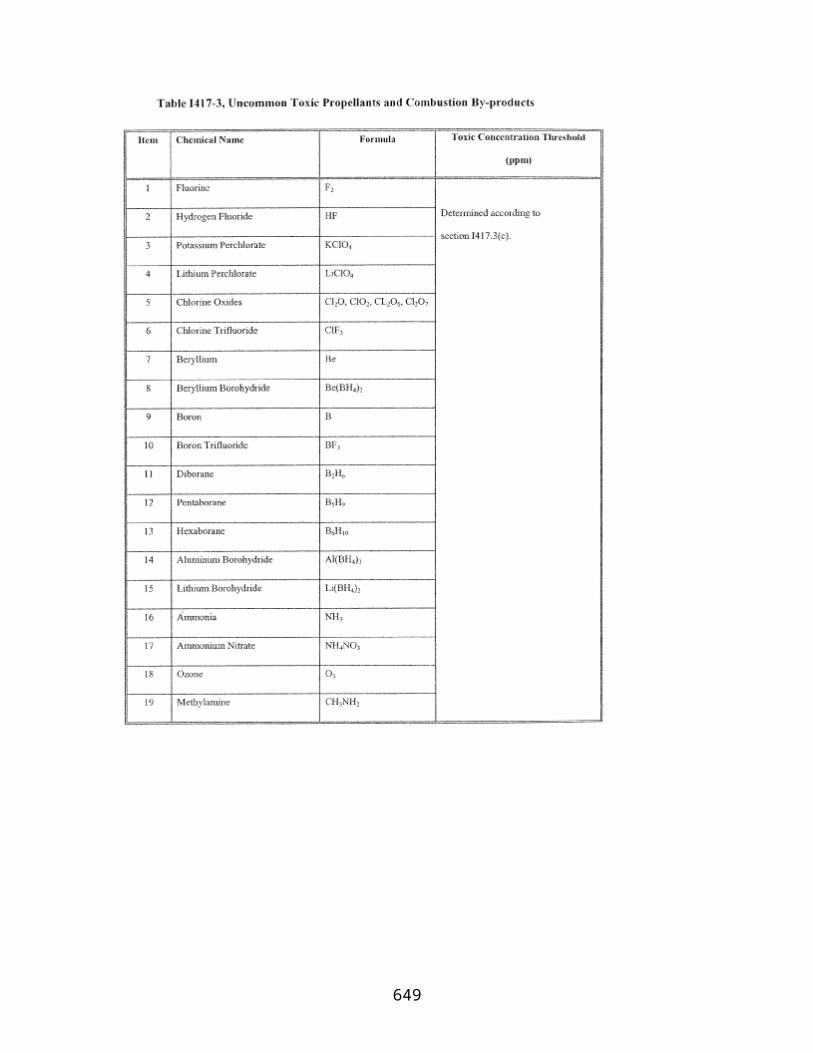
responsible, for any Property Damage they sustain, resulting from Permitted Activities, regardless of fault.
5. Indemnification
Crew Member shall hold harmless and indemnify the United States and its agencies, servants, agents, subsidiaries, employees and assignees, or any of them, from and against liability, loss, or damage arising out of claims brought by anyone for Property Damage or Bodily Injury, including Death, sustained by Crew Member, resulting from Licensed/Permitted Activities.
6. Assurances Under 49 U.S.C. 70112(e)
Notwithstanding any provision of this Agreement to the contrary, Crew Member shall hold harmless the United States and its agencies, servants, agents, employees and assignees, or any of them, from and against liability, loss or damage arising out of claims for Bodily Injury, including Death, or Property Damage, sustained by Crew Member, resulting from Licensed/Permitted Activities, regardless of fault, except to the extent that, as provided in section 6(b) of this Agreement, claims result from willful misconduct of the United States or its agents.
7. Miscellaneous
(a) Nothing contained herein shall be construed as a waiver or release by the United States of any claim by an employee of the United States, respectively, including a member of the Armed Forces of the United States, for Bodily Injury or Property Damage, resulting from Licensed/Permitted Activities.
(b) Notwithstanding any provision of this Agreement to the contrary, any waiver, release, assumption of responsibility or agreement to hold harmless herein shall not apply to claims for Bodily Injury, including Death, or Property Damage resulting from willful misconduct of any of the Parties, the Contractors and Subcontractors of any of the Parties, and in the case of the United States, its agents.
(c) This Agreement shall be governed by and construed in accordance with United States Federal law.
IN WITNESS WHEREOF, the Parties to this Agreement have caused the Agreement to be duly executed by their respective duly authorized representatives as of the date written above.
I [name of Crew Member] have read and understand this agreement and agree that I am bound by it.
Crew Member
649
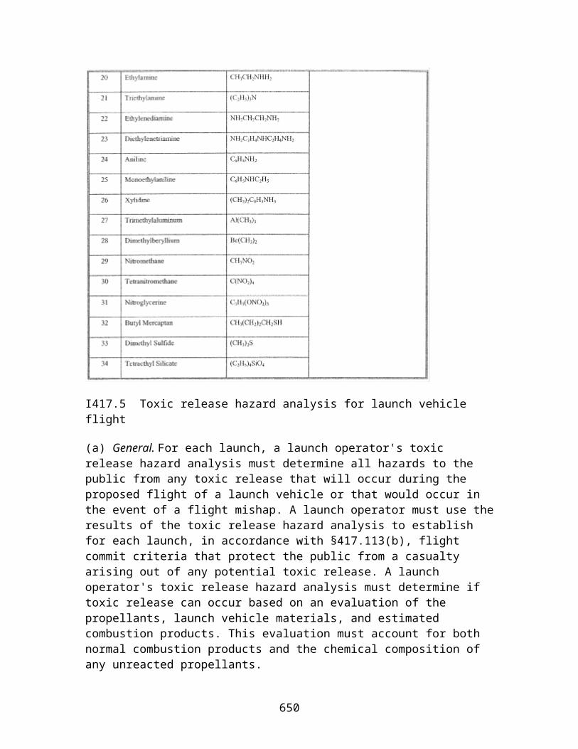
Signature:____________________Printed Name:____________________
Federal Aviation Administration of the Department of Transportation on Behalf of the United States Government
By:____________________Its:____________________
Associate Administrator for Commercial Space Transportation
650

Appendix E to Part 440—Agreement for Waiver of Claims and Assumption of Responsibility for a Space Flight Participant
THIS AGREEMENT is entered into this __ day of ____, by and among [name of Space Flight Participant] (the “Space Flight Participant”) and the Federal Aviation Administration of the Department of Transportation, on behalf of the United States Government (collectively, the “Parties”), to implement the provisions of section 440.17(e) of the Commercial Space Transportation Licensing Regulations, 14 CFR Ch. III (the “Regulations”). This agreement applies to Space Flight Participant's travel on [name of launch or reentry vehicle] of [name of Licensee or Permittee]. In consideration of the mutual releases and promises contained herein, the Parties hereby agree as follows:
1. Definitions
Space Flight Participant means
(a) The above-named Space Flight Participant,
(b) All the heirs, administrators, executors, assignees, next of kin, and estate of the above-named Space Flight Participant , and
(c) Anyone who attempts to bring a claim on behalf of the Space Flight Participant or for damage or harm arising out of the Bodily Injury, including Death, of the Space Flight Participant.
License/Permit means License/Permit No. ____ issued on ____, by the Associate Administrator for Commercial Space Transportation, Federal Aviation Administration, Department of Transportation, to the Licensee/Permittee, including all license/permit orders issued in connection with the License/Permit.
Licensee/Permittee means the Licensee/Permittee and any transferee of the Licensee under 49 U.S.C. Subtitle IX, ch. 701.
United States means the United States and its agencies involved in Licensed/Permitted Activities.
Except as otherwise defined herein, terms used in this Agreement and defined in 49 U.S.C. Subtitle IX, ch. 701—Commercial Space Launch Activities, or in the Regulations, shall have the same meaning as contained in 49 U.S.C. Subtitle IX, ch. 701, or the Regulations, respectively.
2. Waiver and Release of Claims
(a) Space Flight Participant hereby waives and releases claims it may have against the United States, and against its respective Contractors and Subcontractors, for Bodily
651
Injury, including Death, or Property Damage sustained by Space Flight Participant, resulting from Licensed/Permitted Activities, regardless of fault.
(b) The United States hereby waives and releases claims it may have against Space Flight Participant for Property Damage it sustains, and for Bodily Injury, including Death, or Property Damage sustained by its own employees, resulting from Licensed/Permitted Activities, regardless of fault.
3. Assumption of Responsibility
(a) Space Flight Participant shall be responsible for Bodily Injury, including Death, or Property Damage sustained by the Space Flight Participant resulting from Licensed/Permitted Activities, regardless of fault. Space Flight Participant shall hold harmless the United States, and its Contractors and Subcontractors, for Bodily Injury, including Death, or Property Damage sustained by Space Flight Participant from Licensed/Permitted Activities, regardless of fault.
(b) The United States shall be responsible for Property Damage it sustains, and for Bodily Injury, including Death, or Property Damage sustained by its own employees, resulting from Licensed Activities, regardless of fault, to the extent that claims it would otherwise have for such damage or injury exceed the amount of insurance or demonstration of financial responsibility required under sections 440.9(c) and (e), respectively, of the Regulations.
(c) The United States shall be responsible for Property Damage it sustains, resulting from Permitted Activities, regardless of fault, to the extent that claims it would otherwise have for such damage exceed the amount of insurance or demonstration of financial responsibility required under section 440.9(e) of the Regulations.
4. Extension of Assumption of Responsibility and Waiver and Release of Claims
(a) The United States shall extend the requirements of the waiver and release of claims, and the assumption of responsibility as set forth in paragraphs 2(b) and 3(b), respectively, to its Contractors and Subcontractors by requiring them to waive and release all claims they may have against Space Flight Participant, and to agree to be responsible, for any Property Damage they sustain and for any Bodily Injury, including Death, or Property Damage sustained by their own employees, resulting from Licensed Activities, regardless of fault.
(b) The United States shall extend the requirements of the waiver and release of claims, and the assumption of responsibility as set forth in paragraphs 2(b) and 3(c), respectively, to its Contractors and Subcontractors by requiring them to waive and release all claims they may have against Space Flight Participant, and to agree to be responsible, for any Property Damage the Contractors and Subcontractors sustain, resulting from Permitted Activities, regardless of fault.
652

5. Indemnification
Space Flight Participant shall hold harmless and indemnify the United States and its agencies, servants, agents, subsidiaries, employees and assignees, or any of them, from and against liability, loss or damage arising out of claims brought by anyone for Property Damage or Bodily Injury, including Death, sustained by Space Flight Participant, resulting from Licensed/Permitted Activities.
6. Assurances Under 49 U.S.C. 70112(e)
Notwithstanding any provision of this Agreement to the contrary, Space Flight Participant shall hold harmless the United States and its agencies, servants, agents, employees and assignees, or any of them, from and against liability, loss or damage arising out of claims for Bodily Injury, including Death, or Property Damage, sustained by Space Flight Participant, resulting from Licensed/Permitted Activities, regardless of fault, except to the extent that, as provided in section 6(b) of this Agreement, claims result from willful misconduct of the United States or its agents.
7. Miscellaneous
(a) Nothing contained herein shall be construed as a waiver or release by the United States of any claim by an employee the United States, respectively, including a member of the Armed Forces of the United States, for Bodily Injury or Property Damage, resulting from Licensed/Permitted Activities.
(b) Notwithstanding any provision of this Agreement to the contrary, any waiver, release, assumption of responsibility or agreement to hold harmless herein shall not apply to claims for Bodily Injury, including Death, or Property Damage resulting from willful misconduct of any of the Parties, the Contractors, Subcontractors, and agents of the United States, and Space Flight Participant.
(c) This Agreement shall be governed by and construed in accordance with United States Federal law.
IN WITNESS WHEREOF, the Parties to this Agreement have caused the Agreement to be duly executed by their respective duly authorized representatives as of the date written above.
I [name of Space Flight Participant] have read and understand this agreement and agree that I am bound by it.
Space Flight Participant
Signature:____________________Printed Name:____________________
653

Federal Aviation Administration of the Department of Transportation on Behalf of the United States Government
By:____________________Its:____________________
Associate Administrator for Commercial Space Transportation
654

PART 460—HUMAN SPACE FLIGHT REQUIREMENTS
Section Contents
Subpart A—Launch and Reentry with Crew
§ 460.1 Scope. § 460.3 Applicability. § 460.5 Crew qualifications and training. § 460.7 Operator training of crew. § 460.9 Informing crew of risk. § 460.11 Environmental control and life support systems. § 460.13 Smoke detection and fire suppression. § 460.15 Human factors. § 460.17 Verification program. § 460.19 Crew waiver of claims against U.S. Government. §§ 460.20-460.40 [Reserved]
Subpart B—Launch and Reentry with a Space Flight participant
§ 460.41 Scope. § 460.43 Applicability. § 460.45 Operator informing space flight participant of risk. § 460.47 [Reserved] § 460.49 Space flight participant waiver of claims against U.S. Government. § 460.51 Space flight participant training. § 460.53 Security.
Authority: 49 U.S.C. 70105.
Source: Docket No. FAA–2005–23449, 71 FR 75632, Dec. 15, 2006, unless otherwise noted.
Subpart A—Launch and Reentry with Crew
§ 460.1 Scope.
This subpart establishes requirements for crew of a vehicle whose operator is licensed or permitted under this chapter.
§ 460.3 Applicability.
(a) This subpart applies to:
655

(1) An applicant for a license or permit under this chapter who proposes to have flight crew on board a vehicle or proposes to employ a remote operator of a vehicle with a human on board.
(2) An operator licensed or permitted under this chapter who has flight crew on board a vehicle or who employs a remote operator of a vehicle with a human on board.
(3) A crew member participating in an activity authorized under this chapter.
(b) Each member of the crew must comply with all requirements of the laws of the United States that apply to crew.
§ 460.5 Crew qualifications and training.
(a) Each crew member must—
(1) Complete training on how to carry out his or her role on board or on the ground so that the vehicle will not harm the public; and
(2) Train for his or her role in nominal and non-nominal conditions. The conditions must include—
(i) Abort scenarios; and
(ii) Emergency operations.
(b) Each member of a flight crew must demonstrate an ability to withstand the stresses of space flight, which may include high acceleration or deceleration, microgravity, and vibration, in sufficient condition to safely carry out his or her duties so that the vehicle will not harm the public.
(c) A pilot and a remote operator must—
(1) Possess and carry an FAA pilot certificate with an instrument rating.
(2) Possess aeronautical knowledge, experience, and skills necessary to pilot and control the launch or reentry vehicle that will operate in the National Airspace System (NAS). Aeronautical experience may include hours in flight, ratings, and training.
(3) Receive vehicle and mission-specific training for each phase of flight by using one or more of the following—
(i) A method or device that simulates the flight;
(ii) An aircraft whose characteristics are similar to the vehicle or that has similar phases of flight to the vehicle ;
656
(iii) Flight testing; or
(iv) An equivalent method of training approved by the FAA through the license or permit process.
(4) Train in procedures that direct the vehicle away from the public in the event the flight crew abandons the vehicle during flight; and
(5) Train for each mode of control or propulsion, including any transition between modes, such that the pilot or remote operator is able to control the vehicle.
(d) A remote operator may demonstrate an equivalent level of safety to paragraph (c)(1) of this section through the license or permit process.
(e) Each crew member with a safety-critical role must possess and carry an FAA second-class airman medical certificate issued in accordance with 14 CFR part 67, no more than 12 months prior to the month of launch and reentry.
§ 460.7 Operator training of crew.
(a) Implementation of training. An operator must train each member of its crew and define standards for successful completion in accordance with §460.5.
(b) Training device fidelity. An operator must
(1) Ensure that any crew-training device used to meet the training requirements realistically represents the vehicle's configuration and mission, or
(2) Inform the crew member being trained of the differences between the two.
(c) Maintenance of training records. An operator must continually update the crew training to ensure that it incorporates lessons learned from training and operational missions. An operator must—
(1) Track each revision and update in writing; and
(2) Document the completed training for each crew member and maintain the documentation for each active crew member.
(d) Current qualifications and training. An operator must establish a recurrent training schedule and ensure that all crew qualifications and training required by §460.5 are current before launch and reentry.
§ 460.9 Informing crew of risk.
657
An operator must inform in writing any individual serving as crew that the United States Government has not certified the launch vehicle and any reentry vehicle as safe for carrying flight crew or space flight participants. An operator must provide this information—
(a) Before entering into any contract or other arrangement to employ that individual; or
(b) For any crew member employed as of December 23, 2004, as early as possible and prior to any launch in which that individual will participate as crew.
§ 460.11 Environmental control and life support systems.
(a) An operator must provide atmospheric conditions adequate to sustain life and consciousness for all inhabited areas within a vehicle. The operator or flight crew must monitor and control the following atmospheric conditions in the inhabited areas or demonstrate through the license or permit process that an alternate means provides an equivalent level of safety—
(1) Composition of the atmosphere, which includes oxygen and carbon dioxide, and any revitalization;
(2) Pressure, temperature and humidity;
(3) Contaminants that include particulates and any harmful or hazardous concentrations of gases, or vapors; and
(4) Ventilation and circulation.
(b) An operator must provide an adequate redundant or secondary oxygen supply for the flight crew.
(c) An operator must
(1) Provide a redundant means of preventing cabin depressurization; or
(2) Prevent incapacitation of any of the flight crew in the event of loss of cabin pressure.
§ 460.13 Smoke detection and fire suppression.
An operator or crew must have the ability to detect smoke and suppress a cabin fire to prevent incapacitation of the flight crew.
§ 460.15 Human factors.
658

An operator must take the precautions necessary to account for human factors that can affect a crew's ability to perform safety-critical roles, including in the following safety critical areas—
(a) Design and layout of displays and controls;
(b) Mission planning, which includes analyzing tasks and allocating functions between humans and equipment;
(c) Restraint or stowage of all individuals and objects in a vehicle; and
(d) Vehicle operation, so that the vehicle will be operated in a manner that flight crew can withstand any physical stress factors, such as acceleration, vibration, and noise.
§ 460.17 Verification program.
An operator must successfully verify the integrated performance of a vehicle's hardware and any software in an operational flight environment before allowing any space flight participant on board during a flight. Verification must include flight testing.
§ 460.19 Crew waiver of claims against U.S. Government.
Each member of a flight crew and any remote operator must execute a reciprocal waiver of claims with the Federal Aviation Administration of the Department of Transportation in accordance with the requirements of part 440.
§§ 460.20-460.40 [Reserved]
Subpart B—Launch and Reentry with a Space Flight participant
§ 460.41 Scope.
This subpart establishes requirements for space flight participants on board a vehicle whose operator is licensed or permitted under this chapter.
§ 460.43 Applicability.
This subpart applies to:
(a) An applicant for a license or permit under this chapter who proposes to have a space flight participant on board a vehicle;
(b) An operator licensed or permitted under this chapter who has a space flight participant on board a vehicle; and
659

(c) A space flight participant in an activity authorized under this chapter.
§ 460.45 Operator informing space flight participant of risk.
(a) Before receiving compensation or making an agreement to fly a space flight participant, an operator must satisfy the requirements of this section. An operator must inform each space flight participant in writing about the risks of the launch and reentry, including the safety record of the launch or reentry vehicle type. An operator must present this information in a manner that can be readily understood by a space flight participant with no specialized education or training, and must disclose in writing—
(1) For each mission, each known hazard and risk that could result in a serious injury, death, disability, or total or partial loss of physical and mental function;
(2) That there are hazards that are not known; and
(3) That participation in space flight may result in death, serious injury, or total or partial loss of physical or mental function.
(b) An operator must inform each space flight participant that the United States Government has not certified the launch vehicle and any reentry vehicle as safe for carrying crew or space flight participants.
(c) An operator must inform each space flight participant of the safety record of all launch or reentry vehicles that have carried one or more persons on board, including both U.S. government and private sector vehicles. This information must include—
(1) The total number of people who have been on a suborbital or orbital space flight and the total number of people who have died or been seriously injured on these flights; and
(2) The total number of launches and reentries conducted with people on board and the number of catastrophic failures of those launches and reentries.
(d) An operator must describe the safety record of its vehicle to each space flight participant. The operator's safety record must cover launch and reentry accidents and human space flight incidents that occurred during and after vehicle verification performed in accordance with §460.17, and include—
(1) The number of vehicle flights;
(2) The number of accidents and human space flight incidents as defined by section 401.5; and
(3) Whether any corrective actions were taken to resolve these accidents and human space flight incidents.
660

(e) An operator must inform a space flight participant that he or she may request additional information regarding any accidents and human space flight incidents reported.
(f) Before flight, an operator must provide each space flight participant an opportunity to ask questions orally to acquire a better understanding of the hazards and risks of the mission, and each space flight participant must then provide consent in writing to participate in a launch or reentry. The consent must—
(1) Identify the specific launch vehicle the consent covers;
(2) State that the space flight participant understands the risk, and his or her presence on board the launch vehicle is voluntary; and
(3) Be signed and dated by the space flight participant.
§ 460.47 [Reserved]
§ 460.49 Space flight participant waiver of claims against U.S. Government.
Each space flight participant must execute a reciprocal waiver of claims with the Federal Aviation Administration of the Department of Transportation in accordance with the requirements of part 440 of this chapter.
§ 460.51 Space flight participant training.
An operator must train each space flight participant before flight on how to respond to emergency situations, including smoke, fire, loss of cabin pressure, and emergency exit.
§ 460.53 Security.
An operator must implement security requirements to prevent any space flight participant from jeopardizing the safety of the flight crew or the public. A space flight participant may not carry on board any explosives, firearms, knives, or other weapons.
661
