tiremaax cp installation, service and troubleshooting
TRANSCRIPT
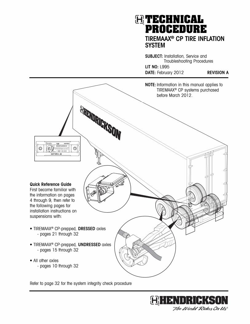
TECHNICALPROCEDURETIREMAAX® CP TIRE INFLATION SYSTEM
SUBJECT: Installation, Service andTroubleshooting Procedures
LIT NO: L995DATE: February 2012 REVISION A
Quick Reference GuideFirst become familiar withthe information on pages4 through 9, then refer tothe following pages forinstallation instructions onsuspensions with:
• TIREMAAX® CP-prepped, DRESSED axles- pages 21 through 32
• TIREMAAX® CP-prepped, UNDRESSED axles- pages 15 through 32
• All other axles- pages 10 through 32
Refer to page 32 for the system integrity check procedure
NOTE: Information in this manual applies toTIREMAAX® CP systems purchasedbefore March 2012.

TIREMAAX® CP INSTALLATION, SERVICE AND TROUBLESHOOTING PROCEDURES
2L995 A
TABLE OF CONTENTS
GENERAL INFORMATION . . . . . . . . . . . . . . . . . . . . . . . . . . . . . . . . . . . . . . . . . . . . . . . . . . . . . . . . . . . .5About this Manual . . . . . . . . . . . . . . . . . . . . . . . . . . . . . . . . . . . . . . . . . . . . . . . . . . . . . . . . . . . . . .5System Overview . . . . . . . . . . . . . . . . . . . . . . . . . . . . . . . . . . . . . . . . . . . . . . . . . . . . . . . . . . . . . . .5Features . . . . . . . . . . . . . . . . . . . . . . . . . . . . . . . . . . . . . . . . . . . . . . . . . . . . . . . . . . . . . . . . . . . . .5System Specifications . . . . . . . . . . . . . . . . . . . . . . . . . . . . . . . . . . . . . . . . . . . . . . . . . . . . . . . . . . .5Component Weights . . . . . . . . . . . . . . . . . . . . . . . . . . . . . . . . . . . . . . . . . . . . . . . . . . . . . . . . . . . .5
OPERATION . . . . . . . . . . . . . . . . . . . . . . . . . . . . . . . . . . . . . . . . . . . . . . . . . . . . . . . . . . . . . . . . . . . . .6System Operation . . . . . . . . . . . . . . . . . . . . . . . . . . . . . . . . . . . . . . . . . . . . . . . . . . . . . . . . . . . . . .6Manually Checking Tire Pressure . . . . . . . . . . . . . . . . . . . . . . . . . . . . . . . . . . . . . . . . . . . . . . . . . . . .6indicator Description . . . . . . . . . . . . . . . . . . . . . . . . . . . . . . . . . . . . . . . . . . . . . . . . . . . . . . . . . . . .6
Indicator on Continuously . . . . . . . . . . . . . . . . . . . . . . . . . . . . . . . . . . . . . . . . . . . . . . . . . . . . . .6How the System Operates . . . . . . . . . . . . . . . . . . . . . . . . . . . . . . . . . . . . . . . . . . . . . . . . . . . . . . . . .7
COMPONENTS . . . . . . . . . . . . . . . . . . . . . . . . . . . . . . . . . . . . . . . . . . . . . . . . . . . . . . . . . . . . . . . . . . .8Component Description . . . . . . . . . . . . . . . . . . . . . . . . . . . . . . . . . . . . . . . . . . . . . . . . . . . . . . . . . .8
Tire Hose (with integral check valve) . . . . . . . . . . . . . . . . . . . . . . . . . . . . . . . . . . . . . . . . . . . . . .8Rotary Joint . . . . . . . . . . . . . . . . . . . . . . . . . . . . . . . . . . . . . . . . . . . . . . . . . . . . . . . . . . . . . . .8Tee Fitting . . . . . . . . . . . . . . . . . . . . . . . . . . . . . . . . . . . . . . . . . . . . . . . . . . . . . . . . . . . . . . . . .8Controller Assembly with Integrated Pressure Control Unit (IPCU) . . . . . . . . . . . . . . . . . . . . . . . . . .8
INSTALLATION . . . . . . . . . . . . . . . . . . . . . . . . . . . . . . . . . . . . . . . . . . . . . . . . . . . . . . . . . . . . . . . . . .10Installation Materials and Supplies . . . . . . . . . . . . . . . . . . . . . . . . . . . . . . . . . . . . . . . . . . . . . . . . .10Installation Introduction . . . . . . . . . . . . . . . . . . . . . . . . . . . . . . . . . . . . . . . . . . . . . . . . . . . . . . . . .10Axle Preparation . . . . . . . . . . . . . . . . . . . . . . . . . . . . . . . . . . . . . . . . . . . . . . . . . . . . . . . . . . . . . .10Component Installation . . . . . . . . . . . . . . . . . . . . . . . . . . . . . . . . . . . . . . . . . . . . . . . . . . . . . . . . .13Axle Hose Installation . . . . . . . . . . . . . . . . . . . . . . . . . . . . . . . . . . . . . . . . . . . . . . . . . . . . . . . . . .13Spindle Plug Installation . . . . . . . . . . . . . . . . . . . . . . . . . . . . . . . . . . . . . . . . . . . . . . . . . . . . . . . . .15Hub Installation Requirements . . . . . . . . . . . . . . . . . . . . . . . . . . . . . . . . . . . . . . . . . . . . . . . . . . . .15Hendrickson Hubcap Spacer Kit Installation . . . . . . . . . . . . . . . . . . . . . . . . . . . . . . . . . . . . . . . . . . .17Rotary Joint Installation . . . . . . . . . . . . . . . . . . . . . . . . . . . . . . . . . . . . . . . . . . . . . . . . . . . . . . . . .17Hubcap Assembly . . . . . . . . . . . . . . . . . . . . . . . . . . . . . . . . . . . . . . . . . . . . . . . . . . . . . . . . . . . . .19Controller Assembly Installation . . . . . . . . . . . . . . . . . . . . . . . . . . . . . . . . . . . . . . . . . . . . . . . . . . .21Wiring Harness Installation . . . . . . . . . . . . . . . . . . . . . . . . . . . . . . . . . . . . . . . . . . . . . . . . . . . . . . .21Axle Vent Installation . . . . . . . . . . . . . . . . . . . . . . . . . . . . . . . . . . . . . . . . . . . . . . . . . . . . . . . . . . .23Control Line Installation . . . . . . . . . . . . . . . . . . . . . . . . . . . . . . . . . . . . . . . . . . . . . . . . . . . . . . . . .23Additional Axles . . . . . . . . . . . . . . . . . . . . . . . . . . . . . . . . . . . . . . . . . . . . . . . . . . . . . . . . . . . . . .24Label Location . . . . . . . . . . . . . . . . . . . . . . . . . . . . . . . . . . . . . . . . . . . . . . . . . . . . . . . . . . . . . . .31
SYSTEM INTEGRITY CHECK . . . . . . . . . . . . . . . . . . . . . . . . . . . . . . . . . . . . . . . . . . . . . . . . . . . . . . . . .32
SYSTEM SETUP . . . . . . . . . . . . . . . . . . . . . . . . . . . . . . . . . . . . . . . . . . . . . . . . . . . . . . . . . . . . . . . . . .32
TROUBLESHOOTING . . . . . . . . . . . . . . . . . . . . . . . . . . . . . . . . . . . . . . . . . . . . . . . . . . . . . . . . . . . . . .32Troubleshooting Introduction . . . . . . . . . . . . . . . . . . . . . . . . . . . . . . . . . . . . . . . . . . . . . . . . . . . . . .32

TIREMAAX® CP INSTALLATION, SERVICE AND TROUBLESHOOTING PROCEDURES
3L995 A
SERVICE PROCEDURES . . . . . . . . . . . . . . . . . . . . . . . . . . . . . . . . . . . . . . . . . . . . . . . . . . . . . . . . . . . .33Setting Target Pressure . . . . . . . . . . . . . . . . . . . . . . . . . . . . . . . . . . . . . . . . . . . . . . . . . . . . . . . . . .33Wiring Harness Replacement . . . . . . . . . . . . . . . . . . . . . . . . . . . . . . . . . . . . . . . . . . . . . . . . . . . . .35
Removal . . . . . . . . . . . . . . . . . . . . . . . . . . . . . . . . . . . . . . . . . . . . . . . . . . . . . . . . . . . . . . . . .35Installation . . . . . . . . . . . . . . . . . . . . . . . . . . . . . . . . . . . . . . . . . . . . . . . . . . . . . . . . . . . . . . .35
Controller Assembly Replacement . . . . . . . . . . . . . . . . . . . . . . . . . . . . . . . . . . . . . . . . . . . . . . . . . .36Removal . . . . . . . . . . . . . . . . . . . . . . . . . . . . . . . . . . . . . . . . . . . . . . . . . . . . . . . . . . . . . . . . .36Installation . . . . . . . . . . . . . . . . . . . . . . . . . . . . . . . . . . . . . . . . . . . . . . . . . . . . . . . . . . . . . . .36
Wheel Removal and Installation . . . . . . . . . . . . . . . . . . . . . . . . . . . . . . . . . . . . . . . . . . . . . . . . . . .38Wheel-End Service (Hub Removal) . . . . . . . . . . . . . . . . . . . . . . . . . . . . . . . . . . . . . . . . . . . . . . . . .38Rotary Joint Detachment (for Hub Removal on HN Spindles) . . . . . . . . . . . . . . . . . . . . . . . . . . . . . . .39Rotary Joint Reattachment . . . . . . . . . . . . . . . . . . . . . . . . . . . . . . . . . . . . . . . . . . . . . . . . . . . . . . .39Hubcap Assembly . . . . . . . . . . . . . . . . . . . . . . . . . . . . . . . . . . . . . . . . . . . . . . . . . . . . . . . . . . . . .39
GLOSSARY . . . . . . . . . . . . . . . . . . . . . . . . . . . . . . . . . . . . . . . . . . . . . . . . . . . . . . . . . . . . . . . . . . . . .40
APPENDIX . . . . . . . . . . . . . . . . . . . . . . . . . . . . . . . . . . . . . . . . . . . . . . . . . . . . . . . . . . . . . . . . . . . . .41
TIREMAAX® CP INSTALLATION, SERVICE AND TROUBLESHOOTING PROCEDURES
4L995 A
IMPORTANT NOTICEHazard signal words (such as Warning or Caution)appear in various locations throughout this publication. Information accented by one of these signal words must be observed at all times.Additional notes are utilized to emphasize areas ofprocedural importance and provide suggestions forease of repair. The following definitions indicate theuse of these signal words as they appear throughoutthe publication.
WARNING: Indicates hazards or unsafepractices which COULD result insevere personal injury or death.
CAUTION: Indicates hazards or unsafepractices which could result indamage to equipment or minorpersonal injury.
NOTE: Additional service information not covered inthe service procedures.
Departure from the instructions, choice of tools, materials and recommended parts mentioned in thispublication may jeopardize the personal safety of theservice technician or vehicle operator.
Always use genuine Hendrickson replacement parts.
Every effort has been made to ensure the accuracy ofall information in this publication. However,Hendrickson makes no expressed or implied warranty or representation based on the enclosedinformation.
The Hendrickson TIREMAAX® tire inflation system isavailable in two versions: TIREMAAX® EC (electroniccontroller) and TIREMAAX® CP (constant pressure).
This document describes installation, service andtroubleshooting procedures for the Hendrickson TIREMAAX CP tire inflation system. It is only applicable to TIREMAAX CP systems.
If you need installation, service and troubleshootinginformation for the Hendrickson TIREMAAX EC tireinflation system, please refer to Hendrickson publication L818, TIREMAAX EC Installation, Serviceand Troubleshooting Procedures, available fromwww.hendrickson-intl.com.
The descriptions and specifications contained in thispublication are current at the time of printing.
Hendrickson reserves the right to discontinue or modify its models and/or procedures and to changespecifications at any time without notice.
Any reference to brand name in this publication ismade as an example of the types of tools and materials recommended for use and should not beconsidered an endorsement. Equivalents may beused.
TIREMAAX® CP INSTALLATION, SERVICE AND TROUBLESHOOTING PROCEDURES
5L995 A
GENERAL INFORMATIONABOUT THIS MANUALThis manual is provided to support the HendricksonTIREMAAX® CP tire inflation system. The manual provides the following information:
• General Information• Operation• Components• Installation• Service• Troubleshooting• Glossary
SYSTEM OVERVIEWThe TIREMAAX CP tire inflation system is designed toautomatically inflate tires that are below their targetpressure setting using compressed air from the trailerair tank.
NOTE: For TIREMAAX CP to function properly, thetrailer air tank pressure must be higher thanthe target tire pressure. TIREMAAX CP is onlycapable of allowing available air tankpressure to reach the tires. It is not capableof supplying pressure above the available airtank pressure.
Air seals and hoses are constantly pressurized at apreset target pressure. A trailer-mounted indicator(figure 2) will turn on when the pressure in one ormore tires is low, or when a system problem occurs.When the trailer-mounted indicator comes on formore than 10 minutes continuously, it is an indication of a potential system or tire leak. Refer tothe Troubleshooting section on page 32 for moreadditional troubleshooting details. The trailer-mountedindicator will not turn on for minimal inflation requirements of less than an airflow of approximately0.7 cfm, helping to avoid operator distraction whenno action is required.
If a tire is low, the remaining tires are protected frompressure loss by integral check valves located ineach tire hose.
FEATURES• Indicator (figure 2) on when system flow exceeds approximately 0.7 cfm
• Checks tire pressure continuously
• Indicator on only when service is required
• Does not pressurize axle tube (helps prevent contamination of air seals)
• Seal and line leaks will not pressurize wheel ends
• No venting at wheel end helps prevent contamination from entering hubcap
• Check-valves located in hoses at tee fitting
• Manual pressure check or fill available at hose end
• Leaky tire detection
• Serviceable filter at supply shutoff valve helps keeplines and seals clean
• Factory set to one of 11 possible target pressures(70, 75, 80, 85, 90, 95, 100, 105, 110, 115, or120 psi) selected by the customer
• In-axle filter prevents hub contamination andallows any wheel-end air leaks to evacuate throughthe axle vent
SYSTEM SPECIFICATIONS• Tire pressure setting range: 70 to 120 psi
• Pressure accuracy: ±1%
• Pressure resolution: 0.5 psi
• Pressure check interval: continuous
• Minimum operating voltage: 9 volts
• Indicator current range: 50mA to 1A
• Inflate capacity (one tire): 10 psi in approx.two minutes
COMPONENT WEIGHTS• Controller assembly: 2.62 lbs.
• Misc. fittings and air line: 1 lb. per axle
• Wire harness: 1 oz. (std)1.4 lbs. (ABS)
• Hubcap spacers (if required) 1 lb. per axle
• Wheel-end hardwaredual wheels 1.7 lbs. per endsuper single wheels 1.4 lbs. per end
• Indicator light kit 1.8 lbs.
TIREMAAX® CP INSTALLATION, SERVICE AND TROUBLESHOOTING PROCEDURES
6L995 A
OPERATIONSYSTEM OPERATIONThe system will pressurize the lines and measure tirepressure by comparing the pressure in the lines andtires to a regulated supply pressure. If the regulatedsupply pressure exceeds the line pressure, the systemassumes one or more tires are low and automaticallystarts to inflate the low tire(s) to the target pressuresetting. The remaining tires are protected from pressure loss by check-valves located in each tirehose. If one or more tires are low, the indicator (figure 2) will turn on and remain on as long as theflow exceeds approximately 0.7 cfm. The system continues to inflate to the proper pressure.
If the indicator (figure 2) remains on for more than10 minutes, the system is attempting to inflate thetires but may not be able to adequately maintainproper tire pressure. The operator should stop andcheck the tires to determine if it is safe to continue tooperate the vehicle and should seek service at thenext opportunity.
NOTE: If a hose is removed or damaged, the systemwill continue to inflate the other low tires.
MANUALLY CHECKING TIRE PRESSURE
WARNING: TO PREVENT INJURY, ALWAYS WEAREYE PROTECTION WHENMAINTAINING OR SERVICING THEVEHICLE.
NOTE: Check valves in the tire hoses help prevent tirepressure loss when a tire hose is removed.You may experience a slight burst of air whenthe hose is disconnected.
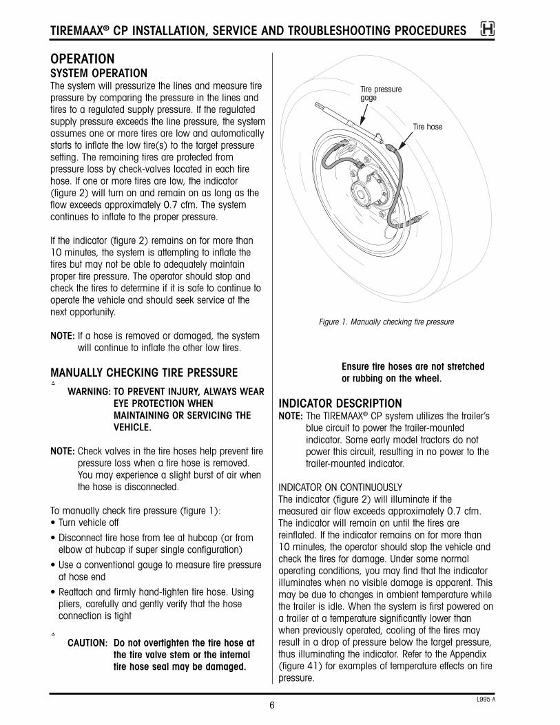
To manually check tire pressure (figure 1):• Turn vehicle off
• Disconnect tire hose from tee at hubcap (or fromelbow at hubcap if super single configuration)
• Use a conventional gauge to measure tire pressureat hose end
• Reattach and firmly hand-tighten tire hose. Usingpliers, carefully and gently verify that the hose connection is tight
CAUTION: Do not overtighten the tire hose atthe tire valve stem or the internaltire hose seal may be damaged.
Ensure tire hoses are not stretchedor rubbing on the wheel.
INDICATOR DESCRIPTIONNOTE: The TIREMAAX® CP system utilizes the trailer’s
blue circuit to power the trailer-mountedindicator. Some early model tractors do notpower this circuit, resulting in no power to thetrailer-mounted indicator.
INDICATOR ON CONTINUOUSLYThe indicator (figure 2) will illuminate if the measured air flow exceeds approximately 0.7 cfm.The indicator will remain on until the tires are reinflated. If the indicator remains on for more than10 minutes, the operator should stop the vehicle andcheck the tires for damage. Under some normal operating conditions, you may find that the indicatorilluminates when no visible damage is apparent. Thismay be due to changes in ambient temperature whilethe trailer is idle. When the system is first powered ona trailer at a temperature significantly lower thanwhen previously operated, cooling of the tires mayresult in a drop of pressure below the target pressure,thus illuminating the indicator. Refer to the Appendix(figure 41) for examples of temperature effects on tirepressure.
Figure 1. Manually checking tire pressure
Tire hose
Tire pressuregage

TIREMAAX® CP INSTALLATION, SERVICE AND TROUBLESHOOTING PROCEDURES
7L995 A
In addition, the indicator may turn on and remain ondue to a significant air line leak or system failure.
HOW THE SYSTEM OPERATESThe system checks the tire pressures continuously. Tomeasure the tire pressure, the system compares thepressure in the lines and tires to a regulated supplypressure. If the regulated supply pressure exceeds theline pressure, the system will begin to inflate the lowtire(s). If the measured air flow exceeds approximately0.7 cfm, the indicator will illuminate while the system is inflating the tire(s) to inform the driver of apotential tire leak. Once the target tire pressure isachieved, the system continuously monitors the tirepressure to maintain this target pressure.
To prevent air from leaking while tire hoses areremoved at the tee or elbow fitting, a check valve(spring type valve core - 2 to 3 psi) is used in eachof the tire hoses.
If the indicator remains lit for an extended period oftime (more than 10 minutes), the driver shouldcheck all the tires for damage and take correctiveactions if applicable.
Typicaltrailer-mounted
indicator
Figure 2. Trailer-mounted indicator
TIREMAAX® CP INSTALLATION, SERVICE AND TROUBLESHOOTING PROCEDURES
8L995 A
COMPONENTSCOMPONENT DESCRIPTIONRefer to figure 3 for major TIREMAAX® CP component illustrations. Refer to figures 21 through 28 for acomplete description of air fittings and hoses.
TIRE HOSE (WITH INTEGRAL CHECK VALVE)• Provides an air passage from the hubcap tee to thetire
• No modification to the standard valve stem or coreis required
• Allows for manual pressure check and fill at thehose end
ROTARY JOINT• Provides a means to allow the air to flow from anon-rotating axle spindle to the rotating hubcap
• Composed of seals and bearings — the seal prevents air leakage from the rotating shaft
• Spindle plug provides a secure surface to mountthe rotary union and provides an air pressure ventin the hubcap during normal use and in the eventof rotary joint damage
TEE FITTING• Includes integral check valve assemblies
• Integral check valves are opened when tire hosesare connected
• Prevents air pressure from escaping while tirehoses are removed
CONTROLLER ASSEMBLY WITH INTEGRATEDPRESSURE CONTROL UNIT (IPCU)• Mounting flanges integral to Lexan® enclosure
• Integrated pressure control unit (IPCU)- controls the flow of air to the tires- has separate supply side (SUPPLY) and delivery side (DELIVERY) ports, see figure 3
- supply pressure port has a serviceable inlet filter to reduce contamination from the air source
- uses pressure differential between regulated supply pressure and tire pressure to control air flow, thus maintaining tire pressure
- turns on the indicator when the measured air flow exceeds approximately 0.7 cfm
- allows the target tire pressure to be reset using a simple procedure and common shop tools
• Shutoff valve- closes supply pressure to controller- shuts off pressure to system during maintenance
• Petcock valve allows trailer-mounted indicator functionality to be verified

TIREMAAX® CP INSTALLATION, SERVICE AND TROUBLESHOOTING PROCEDURES
9L995 A
Figure 3. TIREMAAX® CP components
Indicator
Main power harness (J560 interface)
Controller assembly(shown properly oriented with door hinge at top)
Hubcap and hose assembly
Hose assembly
Checkvalve
Tee fitting
Alternate style teeguard, used onHUS® hubs withbolt-on hubcaps
Rotary joint
Checkvalve
Hoseassembly
NOTE: Refer tofigures 21through 28 fordescriptions ofair fittings andhoses.
Tee fitting guard(not a step)
Integrated pressurecontrol unit (IPCU)
SUPPLY port(air in)
DELIVERY port(air out)
NOTE: Tire hoses mustbe connecteddirectly to the tirevalve stems andthe tee fitting. Donot use valvestem extenders.
Tire hoses, with wheel guards in place on hoseassemblies. Wheel guards help prevent the braidedsteel hoses from abrading the wheel.
Petcockvalve
Shutoffvalve

INSTALLATIONINSTALLATION MATERIALS AND SUPPLIESIn addition to the hardware provided, the installershall provide the following:
• Spindle plug driver and handle* (figure 10), unless the spindle plugs are already installed in theaxle from the factory
• Air lines and fittings (figures 21-28)
• Indicator and wire (figure 20)
• Controller assembly mounting bolts (figure 19)
• Pressure protection valve
*Components unique to TIREMAAX® CP, available only from Hendrickson
INSTALLATION INTRODUCTIONIdentify the bullet item below that describes the condition of your axles and proceed as directed.
• If the TIREMAAX CP system hardware is alreadyinstalled on a dressed axle, skip to the sectiontitled Controller Assembly Installation on page 21.
• If the TIREMAAX CP system axle hose and spindleplugs are already installed on the axle, skip to thesection titled Rotary Joint Installation on page 17.
• If the axles have been pre-drilled but no hardwarehas been installed, skip to the section titledComponent Installation on page 13.
• For retrofit installations, start with the proceduresdescribed below.
AXLE PREPARATIONThe following describes the procedure for preparing aHendrickson axle (figure 4) for TIREMAAX CP systeminstallation.
NOTE: The TIREMAAX CP system is not compatiblewith the castle (cotter pin-locked) spindle nutsystem. Use only the standard three-piecespindle nut system (HN or HP spindles) or theHUS® spindle locking hardware (HUSspindles) with the TIREMAAX CP system.The PRO-TORQ spindle nut system may beused, but it may also require a Hendricksonhubcap spacer kit to provide the necessaryclearance between it and the rotary jointassembly.
WARNING: BLOCK ALL WHEELS BEFOREBEGINNING THIS INSTALLATION
TIREMAAX® CP INSTALLATION, SERVICE AND TROUBLESHOOTING PROCEDURES
10L995 A
PROCEDURE. NEVER WORK UNDERA VEHICLE SUPPORTED ONLY BY AJACK.
1. Block the tires to keep the trailer from moving(figure 5).
2. Exhaust the trailer air system.
3. If the wheel end is oil lubricated, drain the oilfrom the hubcap and discard the oil.
4. Remove the hubcap bolts and hubcap.
Figure 4. Axle spindle identification
HN spindle
HP spindle
HUS® spindle
Figure 5. Trailer preparation
TIREMAAX® CP INSTALLATION, SERVICE AND TROUBLESHOOTING PROCEDURES
11L995 A
5. Remove the spindle plug from the spindle.
6. Remove the in-axle filter.
7. Inspect the spindle plug bore and remove anyburrs or sealant.
8. Check the inside of the spindle to ensure thatthere is a passage through the axle to allowinstallation of the air line.
9. For all INTRAAX® and VANTRAAX® suspensions -locate the three ¼-inch pipe plugs in the axlewrap windows, remove the plugs, and proceedto the Component Installation section on page
13. If the axle does not have pre-drilled holes inthe axle wrap windows, proceed to step 10 forhole drilling details.
For Hendrickson Trailer Axles - locate the three¼-inch pipe plugs in the middle of the axle,remove the plugs, and proceed to theComponent Installation section on page 13. Ifthe axle does not have three pre-drilled holes inthe middle of the axle, proceed to step 10 forhole drilling details.
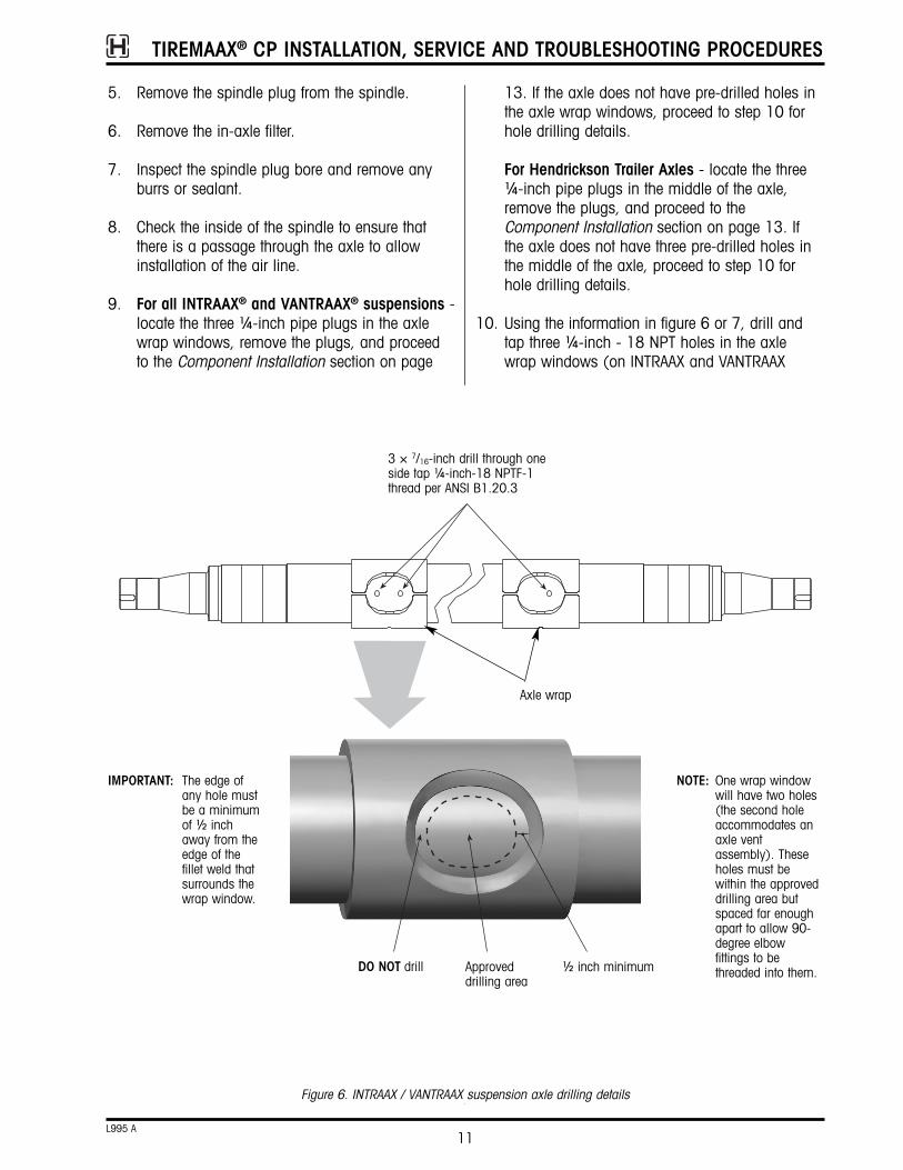
10. Using the information in figure 6 or 7, drill andtap three ¼-inch - 18 NPT holes in the axlewrap windows (on INTRAAX and VANTRAAX
Figure 6. INTRAAX / VANTRAAX suspension axle drilling details
3 × 7/16-inch drill through oneside tap ¼-inch-18 NPTF-1thread per ANSI B1.20.3
IMPORTANT: The edge ofany hole mustbe a minimumof ½ inchaway from theedge of thefillet weld thatsurrounds thewrap window.
NOTE: One wrap windowwill have two holes(the second holeaccommodates anaxle ventassembly). Theseholes must bewithin the approveddrilling area butspaced far enoughapart to allow 90-degree elbowfittings to bethreaded into them.Approved
drilling area½ inch minimumDO NOT drill
Axle wrap
TIREMAAX® CP INSTALLATION, SERVICE AND TROUBLESHOOTING PROCEDURES
12L995 A
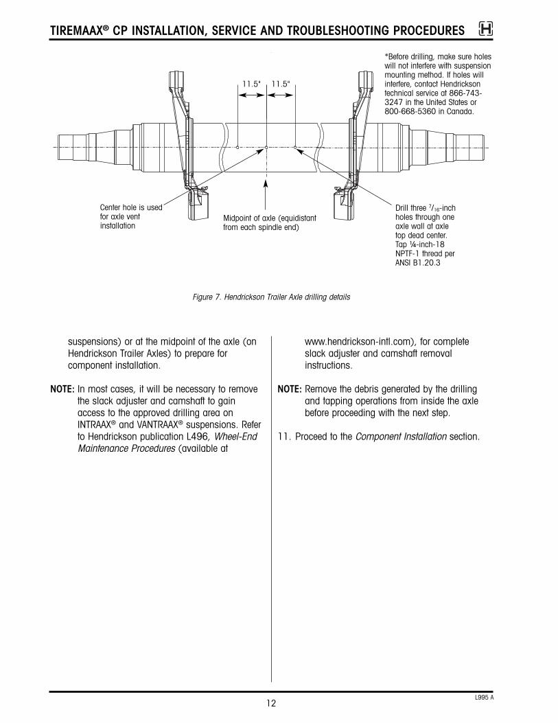
Drill three 7/16-inchholes through oneaxle wall at axletop dead center.Tap ¼-inch-18NPTF-1 thread perANSI B1.20.3
Midpoint of axle (equidistantfrom each spindle end)
11.5" 11.5"
Figure 7. Hendrickson Trailer Axle drilling details
suspensions) or at the midpoint of the axle (onHendrickson Trailer Axles) to prepare forcomponent installation.
NOTE: In most cases, it will be necessary to removethe slack adjuster and camshaft to gainaccess to the approved drilling area onINTRAAX® and VANTRAAX® suspensions. Referto Hendrickson publication L496, Wheel-EndMaintenance Procedures (available at
www.hendrickson-intl.com), for completeslack adjuster and camshaft removal instructions.
NOTE: Remove the debris generated by the drillingand tapping operations from inside the axlebefore proceeding with the next step.
11. Proceed to the Component Installation section.
Center hole is usedfor axle ventinstallation
*Before drilling, make sure holeswill not interfere with suspensionmounting method. If holes willinterfere, contact Hendricksontechnical service at 866-743-3247 in the United States or800-668-5360 in Canada.
TIREMAAX® CP INSTALLATION, SERVICE AND TROUBLESHOOTING PROCEDURES
13L995 A
COMPONENT INSTALLATIONRefer to the following assembly procedures to complete the installation of the TIREMAAX® CP tire inflation system. Component installation proceduresinclude:
• Axle hose installation
• Spindle plug installation
• Hub installation requirements
• Hendrickson hubcap spacer kit installation
• Rotary joint installation
• Hubcap assembly
• Controller assembly installation
• Wiring harness installation
• Axle vent and control line installation
• Tire hose installation
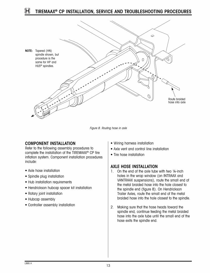
AXLE HOSE INSTALLATION1. On the end of the axle tube with two ¼-inch
holes in the wrap window (on INTRAAX andVANTRAAX suspensions), route the small end ofthe metal braided hose into the hole closest tothe spindle end (figure 8). On HendricksonTrailer Axles, route the small end of the metalbraided hose into the hole closest to the spindle.
2. Making sure that the hose heads toward thespindle end, continue feeding the metal braidedhose into the axle tube until the small end of thehose exits the spindle end.
Figure 8. Routing hose in axle
Route braidedhose into axle
NOTE: Tapered (HN)spindle shown, butprocedure is thesame for HP andHUS® spindles.

TIREMAAX® CP INSTALLATION, SERVICE AND TROUBLESHOOTING PROCEDURES
14L995 A
3. Thread the large adapter end of the axle hoseassembly into the axle and tighten to 20 ft. lbs.(27.1 N•m) of torque (figure 9).
4. If not already present, cut an inch-wide slit in thecenter of the axle filter and feed the metal braidedhose through the slit in the filter. Push the axlefilter into the spindle cavity (figure 9).
5. Remove the protective coverings from the end ofthe axle hose assembly and blow air through thehose assembly to remove any debris.
6. Repeat steps one through five on the other end ofthe axle. Leave the axle vent hole (figure 9)vacant for now. This hole will be used toaccommodate the axle vent in a later installation.
Figure 9. Installed position of hose assembly
Thread adapterinto axle, tightento 20 ft. lbs.(27.1 N•m) oftorque
NOTE: Tapered (HN)spindle shown, butprocedure is thesame for HP andHUS® spindles.
Filter
Axle vent hole

TIREMAAX® CP INSTALLATION, SERVICE AND TROUBLESHOOTING PROCEDURES
15L995 A
SPINDLE PLUG INSTALLATION1. On one end of the axle, route the end of the
braided hose through the center of the spindleplug (figure 10).
2. With the spindle plug breather hole orientedtoward the pivot bushing (figure 10), place theplug assembly against the spindle end.
3. Route the braided hose into the center of the plugdriver and press the plug into the spindle enduntil the driver bottoms on the end of the spindle.
NOTE: The driver regulates the correct installationdepth. Refer to Hendrickson publication B113,TIREMAAX® Spindle Plug Installation Depth(available from www.hendrickson-intl.com) forcomplete installation details.
4. Repeat steps one through three on the other endof the axle.
HUB INSTALLATION REQUIREMENTSWARNING: A minimum hub bore depth is
required when installing theTIREMAAX CP system (figure 11).This hub requirement helps keep theproper clearance between the rotaryjoint assembly and the spindle nutsystem (figure 11), thus preventingcontact or interference betweenthese parts which could result inwheel-end failure and severepersonal injury or death.
Any hub may be used with the TIREMAAX CP system,provided a minimum hub bore depth requirement(dimension “A” in figure 12) is maintained.
If the hub bore dimension is greater than or equal tothe dimension shown in the chart in figure 12, youmay use the hub “as is” with the TIREMAAX CP system.
Plug driverhandle
Spindle plug with breather holeoriented toward pivot bushing
Plug driver
Braided hose
Figure 10. Spindle plug installation
NOTE: Tapered (HN) spindleshown, but procedureis the same for HPand HUS® spindles.
Filter
1 2
Item Name Part Number “A” Dimension Spindle Type
1 Plug driver S-28146-1 1.75 inches HN
1 Plug driver S-28146-2 2.50* inches HP*
1 Plug driver S-28146-3 2.75* inches HP* & HUS
2 Plug driver handle S-27399 — —
Plug Driver and Handle Assembly Ordering Information
“A”
* Before March 28, 2003, Hendrickson manufactured HP spindles with both 2.5" and 2.75" inner borediameters. After this date, the HP spindle bore was standardized at 2.75".
Orient spindle plugbreather hole towardpivot bushing

TIREMAAX® CP INSTALLATION, SERVICE AND TROUBLESHOOTING PROCEDURES
16L995 A
Figure 11. TIREMAAX® CP hub requirement
Hub
Rotary jointassembly
Spindle nutsystem (typical)
a. b.
Minimumhub boredepth
Figure 12. Minimum hub bore depth
HN spindle
HP spindle
Dimension “A” is the minimum hub bore depthrequired to install the TIREMAAX CP system and ismeasured from the bottom of the bearing cup tothe hubcap mounting surface.
TIREMAAX® CP INSTALLATION, SERVICE AND TROUBLESHOOTING PROCEDURES
17L995 A
ROTARY JOINT INSTALLATIONNOTE: The hubs and drums should be installed
before installing the rotary joint assemblies.
There are two styles of rotary joint assembly (figure14): one with a threaded axle hose connector (current production) and one with a barbed axle hoseconnector (earlier style). Use the procedure belowthat matches your rotary joint and axle hose hardware.
Figure 13. Hubcap spacer kit installation
Hubcap
Gasket
Spacer
Gasket
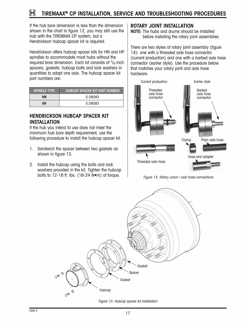
If the hub bore dimension is less than the dimensionshown in the chart in figure 12, you may still use thehub with the TIREMAAX CP system, but aHendrickson hubcap spacer kit is required.
Hendrickson offers hubcap spacer kits for HN and HPspindles to accommodate most hubs without therequired bore dimension. Each kit consists of 3/8-inchspacers, gaskets, hubcap bolts and lock washers inquantities to adapt one axle. The hubcap spacer kitpart numbers are:
HENDRICKSON HUBCAP SPACER KITINSTALLATIONIf the hub you intend to use does not meet the minimum hub bore depth requirement, use the following procedure to install the hubcap spacer kit.
1. Sandwich the spacer between two gaskets asshown in figure 13.
2. Install the hubcap using the bolts and lockwashers provided in the kit. Tighten the hubcapbolts to 12-18 ft. lbs. (16-24 N•m) of torque.
HN
HP
S-28040
S-28093
SPINDLE TYPE HUBCAP SPACER KIT PART NUMBER Threadedaxle hoseconnector
Barbedaxle hoseconnector
Threaded axle hose
Plain axle hose
Hose end adapter
Figure 14. Rotary union / axle hose connections
Clamp
Current production Earlier style
TIREMAAX® CP INSTALLATION, SERVICE AND TROUBLESHOOTING PROCEDURES
18L995 A
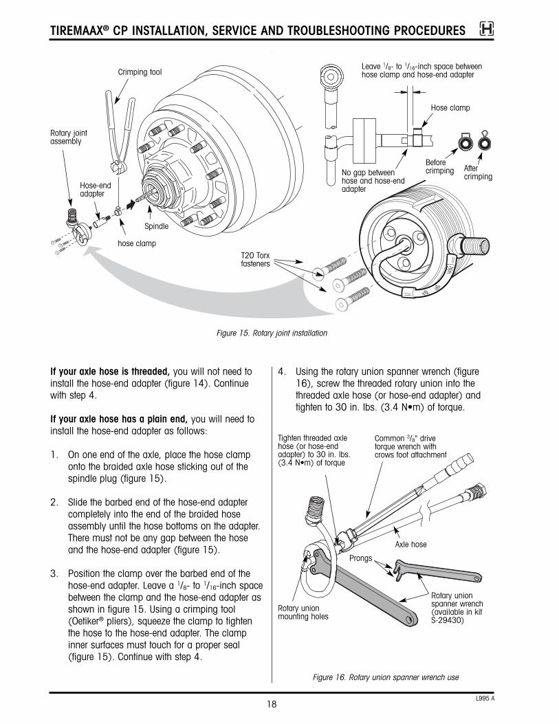
4. Using the rotary union spanner wrench (figure16), screw the threaded rotary union into thethreaded axle hose (or hose-end adapter) andtighten to 30 in. lbs. (3.4 N•m) of torque.
If your axle hose is threaded, you will not need toinstall the hose-end adapter (figure 14). Continuewith step 4.
If your axle hose has a plain end, you will need toinstall the hose-end adapter as follows:
1. On one end of the axle, place the hose clamponto the braided axle hose sticking out of thespindle plug (figure 15).
2. Slide the barbed end of the hose-end adaptercompletely into the end of the braided hoseassembly until the hose bottoms on the adapter.There must not be any gap between the hoseand the hose-end adapter (figure 15).
3. Position the clamp over the barbed end of thehose-end adapter. Leave a 1/8- to 1/16-inch spacebetween the clamp and the hose-end adapter asshown in figure 15. Using a crimping tool(Oetiker® pliers), squeeze the clamp to tightenthe hose to the hose-end adapter. The clampinner surfaces must touch for a proper seal(figure 15). Continue with step 4.
Figure 15. Rotary joint installation
Crimping tool
Beforecrimping After
crimping
Rotary jointassembly
Leave 1/8- to 1/16-inch space betweenhose clamp and hose-end adapter
Spindle
hose clampT20 Torxfasteners
Hose-endadapter
No gap betweenhose and hose-endadapter
Hose clamp
Rotary union spanner wrench(available in kit S-29430)
Figure 16. Rotary union spanner wrench use
Tighten threaded axlehose (or hose-endadapter) to 30 in. lbs.(3.4 N•m) of torque
Axle hose
Prongs
Rotary unionmounting holes
Common 3/8" drivetorque wrench withcrows foot attachment

TIREMAAX® CP INSTALLATION, SERVICE AND TROUBLESHOOTING PROCEDURES
19L995 A
NOTE: The rotary union spanner wrench serves twopurposes. It offers a convenient way to holdthe rotary union stationary while the threadedaxle hose connection is tightened. And sincethe rotary union is manufactured in twohalves, the prongs keep both halves of therotary union from rotating while the axle hoseconnection is being made, thereby ensuringthat the mounting holes in both halves of therotary union stay aligned.
5. Push the rotary union / axle hose assembly intothe spindle plug, aligning the holes in the rotaryunion with the threaded holes in the spindleplug.
IMPORTANT: To align the holes, rotate the rotaryunion / axle hose assembly CLOCKWISEONLY. This ensures that the torquedconnection will not loosen.
6. Insert the three T20 Torx fasteners into the rotaryjoint assembly and fasten to the spindle plug(figure 15). Tighten the fasteners to 45 ±5 in.lbs. (5 ±½ N•m) of torque.
7. Rotate the rotary joint assembly one full turn.Make sure that the steel air tube does not contactany part of the spindle or spindle nut system.
8. Repeat steps one through seven on the otherside of the axle.
Figure 17. Completed installation of rotary joint assembly
Spindle
HUBCAP ASSEMBLY1. Place a hubcap gasket over the rotary joint exit
tube and bulkhead adapter.
2. Lubricate the O-ring on the rotary joint bulkheadadapter. Use the same lubricant as is used in thehub or a light film of #2 grease, white lithiumgrease or Vaseline®.
3. From the inside, insert the bulkhead adapterthrough the hole in the hubcap labeled “Air”.
4. Align the flat on the bulkhead adapter with the anti-rotation flat in the hubcap (figure 18).
Note the orientation indicator on the top of thebulkhead adapter threads (figure 18, view a).Use this indicator (some models have a dot,other models have a notch) to properly orient thebulkhead adapter in the hubcap hole. When theflat on the bulkhead adapter is properly alignedwith the anti-rotation flat in the hubcap, theorientation indicator will face outboard (figure 18,view b).
WARNING: Failure to properly align the flats asdescribed above will result in wheel-end contamination and could lead towheel-end failure.
Do not use pliers or any kind of wrench to pullthe bulkhead adapter up through the hole in thehubcap. This could cause the bulkhead adapterto rotate before it engages the flat in thehubcap, potentially damaging the rotary unionor hubcap.
Attach the jam nut and hand tighten. Whenproperly seated, the top of the bulkhead adapterwill be flush (or higher) with the top of the jamnut when hand tightened (figure 18 view c).
NOTE: If wheels are installed, refer to figure 29 todetermine the correct “clocking” of the hubcap.The wheel must be properly “clocked” to thehubcap to prevent the hoses from rubbing onthe wheel. Failure to properly “clock” thewheels may result in hose failure.
5. Install the hubcap. If the hubcap is a screw-onstyle used on the HUS hub, tighten it to 50-100ft. lbs. (68-137 N•m) of torque. If the hubcap is

TIREMAAX® CP INSTALLATION, SERVICE AND TROUBLESHOOTING PROCEDURES
20L995 A
Figure 18. Hubcap to bulkhead adapter connection details
Rotary joint bulkhead adapter
Nut
Hubcap
Rotary joint exit tubeSpindle
Anti-rotation flatFlat onbulkheadadapter
Hubcap
Orientation indicator(could be a dotor a notch)
Indicatorlines upwith flat,provides a visualreferencewhenbulkheadadapter isinserted intohubcap.
Flat When bulkhead adapter is properlyinserted in hubcap, indicator facesoutboard (away from hubcap).
When properly seated, bulkheadadapter is flush with top of jam nutwhen jam nut is hand tightened.
Bulkhead adapter Jam nut
a. b. c.
a bolt-on style used on the other hubs, tightenthe hubcap bolts to 12-18 ft. lbs. (16-24 N•m)of torque.
6. Tighten the rotary joint jam nut to 15 ft. lbs. (20 N•m) of torque.
7. For oil filled hubs, install lubricant in the wheelend to the correct level.

TIREMAAX® CP INSTALLATION, SERVICE AND TROUBLESHOOTING PROCEDURES
21L995 A
Figure 19. Controller assembly installation
HendricksonK-2® slider box
Finished view
Use existingholes inbottom flangeof crossmember
Mounting bracket
drilling holes in the cross member. On slider suspensions, the bracket and controller assemblymust be mounted below the cross member as shownin figure 19 to avoid interference with the slider stopbar. On non-slider suspensions, the controller can bemounted below the cross member as shown in figure19 or flush mounted to the vertical surface of thecross member if desired, since slider stop bar interference is not an issue.
For slider suspensions1. Attach each corner of the controller assembly to
the bracket with the four 5/16-inch bolts, washersand nuts as shown in figure 19, view A. Orientthe enclosure so that the door hinge is at the topand the petcock valve points down.
2. Attach the controller and bracket assembly to theexisting holes in the bottom surface of the crossmember as shown in figure 19, view B.
WARNING Failure to properly orient thecontroller and mounting bracket asshown in figure 19 and describedabove will result in slider stop barinterference and controller assemblydamage.
For non-slider suspensionsUse the slider assembly mounting method describedabove, or attach each corner of the controllerassembly directly to the vertical surface of the crossmember with the four 5/16-inch bolts, washers andnuts (figure 19). Orient the enclosure so that the doorhinge is at the top and the petcock valve points down(figure 19).
CAUTION: The controller assembly must bemounted so that the door hinge is atthe top and the petcock valve pointsdown (figure 19).
WIRING HARNESS INSTALLATIONTIREMAAX® CP comes standard with a two-wire, 18-inch long harness (figure 20). The red wire of thisharness is the indicator power lead, it connects to thetrailer-mounted indicator. The blue wire must beconnected to 12 VDC vehicle power. The terminationof these wires is the responsibility of the installer.Terminals and connectors must be weatherproof, andcorrosion prevention compound must be used on allconnectors. Refer to TMC RP 113, 114, 154 and704 for recommended wiring practices.
Forward
Slider suspensions Non-slider suspensions
Finished view
CONTROLLER ASSEMBLY INSTALLATIONHendrickson recommends the forwardmost crossmember as the controller assembly mountinglocation (figure 19). A mounting bracket is includedso the controller assembly can be mounted without
NOTE: Controller assemblymust be mounted sothat the door hinge isat the top and thepetcock valve pointsdown
Mountinghardware(x2)
view A
view B
Alternative slider mountingattaches controller to pre-drilled holes in slider crossmember. Mount as shownto avoid stop bar.
TIREMAAX® CP INSTALLATION, SERVICE AND TROUBLESHOOTING PROCEDURES
22L995 A
Figure 20. Trailer wiring harness installation
J560 interface
Trailer-mountedIndicator
These componentsprovided by trailermanufacturer (notincluded withTIREMAAX® CP)
Five-pin Packard
To controllerassemblyconnector
ToABS
Standardharness
Premium, ABS-ready harness
Red (indicatorpower)
Blue (12 VDCpower)
Indicator power lead
Use an internalground or run adedicatedground wire fromthe indicator tothe plug thatconnects thetrailer to the towvehicle.
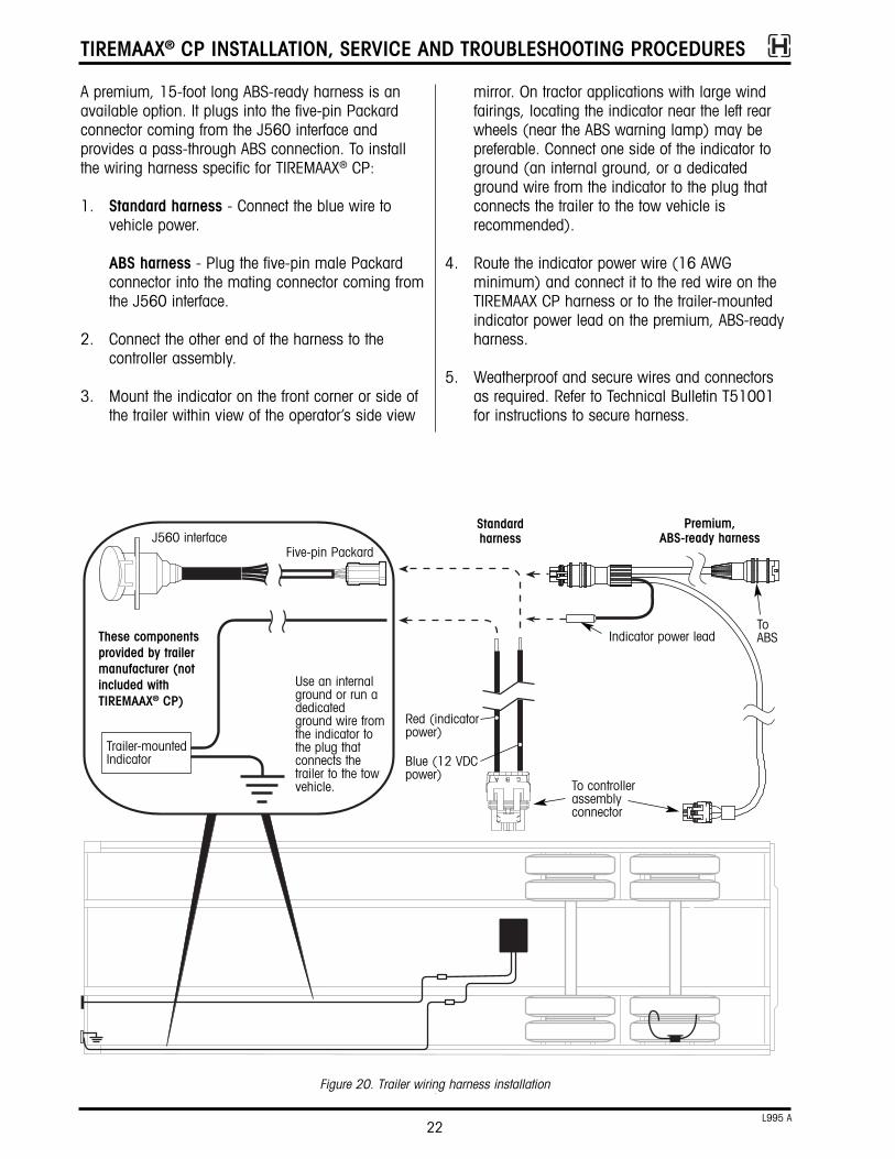
A premium, 15-foot long ABS-ready harness is anavailable option. It plugs into the five-pin Packardconnector coming from the J560 interface andprovides a pass-through ABS connection. To installthe wiring harness specific for TIREMAAX® CP:
1. Standard harness - Connect the blue wire tovehicle power.
ABS harness - Plug the five-pin male Packardconnector into the mating connector coming fromthe J560 interface.
2. Connect the other end of the harness to thecontroller assembly.
3. Mount the indicator on the front corner or side ofthe trailer within view of the operator’s side view
mirror. On tractor applications with large windfairings, locating the indicator near the left rearwheels (near the ABS warning lamp) may bepreferable. Connect one side of the indicator toground (an internal ground, or a dedicatedground wire from the indicator to the plug thatconnects the trailer to the tow vehicle isrecommended).
4. Route the indicator power wire (16 AWGminimum) and connect it to the red wire on theTIREMAAX CP harness or to the trailer-mountedindicator power lead on the premium, ABS-readyharness.
5. Weatherproof and secure wires and connectorsas required. Refer to Technical Bulletin T51001for instructions to secure harness.

TIREMAAX® CP INSTALLATION, SERVICE AND TROUBLESHOOTING PROCEDURES
23L995 A
Figure 21. Typical axle vent installation
90 degree, ¼-inchNPT to 3/8-inch nylontubing adapter
3/8-inch outsidediameter coiledair brake tubing
Duck bill check valve(end must point down)
Duck bill check valve(end must point down)
Suspension beam
Axle wrap
Axle
AXLE VENT INSTALLATION1. Install a 90 degree, ¼-inch NPT male to 3/8-inch
nylon tubing adapter in the remaining ¼-inchthreaded hole in the axle tube (figure 21).
2. Loop the 3/8-inch outside diameter coiled tubingaround the axle. On INTRAAX / VANTRAAXsuspensions, loop the coiled tubing around theaxle inside the suspension beam as shown infigure 21. If not already installed, attach the duckbill check valve to the tubing making sure theend points down to prevent contamination (figure21). To attach the duck bill check valve, slidethe duck bill check valve onto the tubing andsecure with the provided clamp. Do not use glueor any other substance that could plug the duckbill valve.
CAUTION: To prevent contamination of theaxle, ensure the adapters and theduck bill check valve are securelyfastened and the duck bill checkvalve-end points down.
WARNING: Failure to properly install axle ventmay result in wheel-endpressurization and/or water ingestion,which could cause wheel-end failureand severe personal injury or death.
CONTROL LINE INSTALLATIONProper TIREMAAX® CP operation requires correct airline diameters and lengths. The following diagrams (figures 22-28) show air brake tubing lengths andsizes and associated fittings required to complete thesystem installation. Control line routing recommendations are also included.
CAUTION: To prevent twisting the air line insidethe axle when tightening fittings tothe axle hose fitting, use a wrenchto hold the axle hose fitting.
CAUTION: Proper TIREMAAX CP operationrequires correct air line diametersand lengths. Installation sizes andlengths must be within limits shown.
CAUTION: Proper TIREMAAX CP operationrequires correct air line connections.All junctions of two or more ¼-inchlines must increase to 3/8-inch linefor adequate air flow.
CAUTION: To prevent TIREMAAX CPcontamination, do not install fittingson the bottom of the trailer air tank.
NOTE: INTRAAX / VANTRAAX suspension shown, butaxle vent installation procedure is the samefor Hendrickson Trailer Axles. On these axles,the vent tube is installed in the center hole(refer to figure 7).

TIREMAAX® CP INSTALLATION, SERVICE AND TROUBLESHOOTING PROCEDURES
24L995 A
Loop hose around suspensionbeam as shown**
Figure 23. Suggested control line installation details for Top Mount, Narrow Bushing, Standard Duty Models (HKANT, AANT, AAZNT)
Without SURELOK®
With SURELOK Route control line through hole insuspension beam or beam extension**
Route control line throughhole in beam extension
Grommet
Grommet
Route control line througheither hole in suspensionbeam*
** It is the OEMs responsibility to route air lines and orient axleconnector fittings so as to eliminate interference between slackadjusters and air lines.
*On top mount, wide bushing, standard duty models withoutSURELOK, it is permissible to route the control line througheither hole in the suspension beam. Just orient the axleconnector fitting to obtain the best slack adjuster / air lineclearance.
Figure 22. Suggested control line installation details for Top Mount, Wide Bushing, Standard Duty Models (AAT, HKAT)
ADDITIONAL AXLESFor systems with three or four axles, observe theinstallation requirements as shown in the followingdiagrams (figures 22-28). Extend the main 3/8-inchrun as necessary. However, all total line lengths muststill remain within the limits listed in the diagrams.

TIREMAAX® CP INSTALLATION, SERVICE AND TROUBLESHOOTING PROCEDURES
25L995 A
Figure 25. Suggested control line installation details for Low Ride, Short Beam, Narrow Bushing, Standard Duty Models (AANLS 20K)
Route control line throughhole in suspension beam**
Route control line through holein suspension beam**
Figure 24. Suggested control line installation details for Low Ride, Wide Bushing, Standard Duty (AAL 23K, AAL 25K, AAZL, AAL 30K);Low Ride, Wide Bushing, Extreme Duty (AAEDL 30K); and Top Mount, Wide Bushing, Extreme Duty (AAEDT 30K) Models
Figure 25a. Suggested control line installation details for Low Ride, Narrow Bushing, Standard Duty Models (AANL)
Route control line throughhole in suspension beam**
** It is the OEMs responsibility to route air lines and orient axleconnector fittings so as to eliminate interference between slackadjusters and air lines.

TIREMAAX® CP INSTALLATION, SERVICE AND TROUBLESHOOTING PROCEDURES
26L995 A
C
C
B
B
H
H
A
B
C
D
E
F
G
H
I
D
E E
D
DE
I
EJ
I
J
C
J
GF
A
KLA
K
L
Front
Controller assembly
Trailer air tank
Air line 3/8-inch OD nylon air brake tubing; any length
Item Description
Air line 3/8-inch OD nylon air brake tubing; up to 15 feet total system length
Air line ¼-inch OD nylon air brake tubing; 30 to 50 feet total system length
Axle connector 90-degree elbow, 1/8-inch NPT male to ¼-inch NTA
Axle hose fitting 1/8-inch NPT female
Controller IN fitting ¼-inch NPT male to 3/8-inch NTA
Controller OUT fitting run tee: 1/8-inch NPT male, 3/8-inch NTA, 3/8-inch NTA
Tee assembly ¼-inch NPT union tee, two ¼-inch NTA fittings and one 3/8-inch NTA fitting (four total fittings)
Axle vent fitting 90-degree elbow, ¼-inch NPT male to 3/8-inch NTA
NTA = nylon tubing adapter
Figure 26. Typical TIREMAAX CP plumbing schematic — two axles with 3/8- and ¼-inch lines
Air line 3/8-inch OD nylon air brake tubing; one loop around axle with duck bill check valve on end
Pressure protection valve required; 70 psi minimum closing pressure; existing suspension valve can be used
PPV OUT fitting run tee: ¼-inch NPT male, 3/8-inch NTA, 3/8-inch NTA
To height control valve
= included with TIREMAAX® CP-prepped axles
NOTE: To maintain adequateairflow, all air lines cominginto and going out of thecontroller assembly must be3/8 inch, and all junctions oftwo or more ¼-inch linesmust be supplied by 3/8-inchline.
TIREMAAX® CP INSTALLATION, SERVICE AND TROUBLESHOOTING PROCEDURES
27L995 A
A
B
C
D
E
F
G
H
B
C
D
C
G
H
I
F
J
D
AAI
J
E
Front
Controller assembly
Trailer air tank
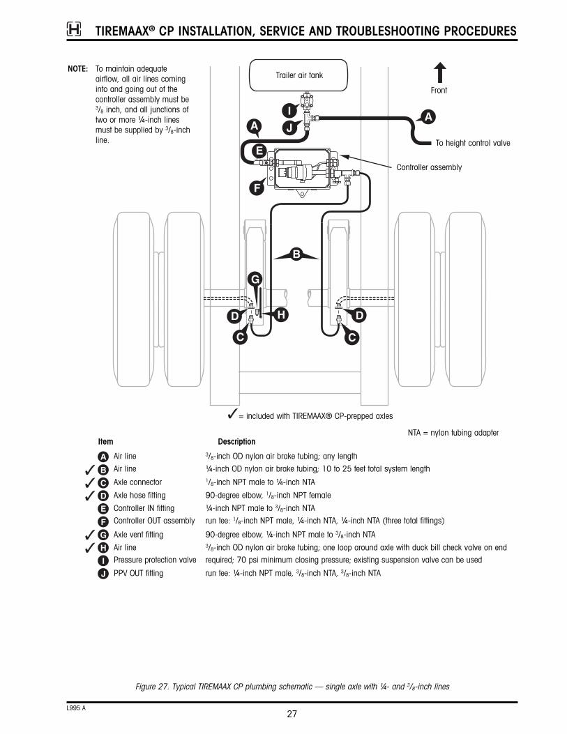
Air line 3/8-inch OD nylon air brake tubing; any length
Item Description
Air line ¼-inch OD nylon air brake tubing; 10 to 25 feet total system length
Axle connector 1/8-inch NPT male to ¼-inch NTA
Axle hose fitting 90-degree elbow, 1/8-inch NPT female
Controller IN fitting ¼-inch NPT male to 3/8-inch NTA
Controller OUT assembly run tee: 1/8-inch NPT male, ¼-inch NTA, ¼-inch NTA (three total fittings)
Axle vent fitting 90-degree elbow, ¼-inch NPT male to 3/8-inch NTA
NTA = nylon tubing adapter
Figure 27. Typical TIREMAAX CP plumbing schematic — single axle with ¼- and 3/8-inch lines
Air line 3/8-inch OD nylon air brake tubing; one loop around axle with duck bill check valve on endPressure protection valve required; 70 psi minimum closing pressure; existing suspension valve can be used
PPV OUT fitting run tee: ¼-inch NPT male, 3/8-inch NTA, 3/8-inch NTA
To height control valve
= included with TIREMAAX® CP-prepped axles
NOTE: To maintain adequateairflow, all air lines cominginto and going out of thecontroller assembly must be3/8 inch, and all junctions oftwo or more ¼-inch linesmust be supplied by 3/8-inchline.

TIREMAAX® CP INSTALLATION, SERVICE AND TROUBLESHOOTING PROCEDURES
28L995 A
C
A
B
C
D
E
F
G
H
I
J
K
OR
D
H
BE E
D
DE
I
EJ
I
J
B
G
K
A A
L
FL
Front
ControllerassemblyTrailer air tank
Plug
To additional axles(four axles maximum per controller)
Air line 3/8-inch OD nylon air brake tubing; any length
Item Description
Air line 3/8-inch OD nylon air brake tubing; up to 15 feet total system length
Air line ¼-inch OD nylon air brake tubing; 30 to 50 feet total system length
Axle connector 90-degree elbow, 1/8-inch NPT male to ¼-inch NTA
Axle hose fitting 1/8-inch NPT female
Controller IN fitting ¼-inch NPT male to 3/8-inch NTA
Controller OUT fitting 1/8-inch NPT male to 3/8-inch NTA
Junction manifold 3/8-inch NTA inlet, ¼-inch NTA outlets
Axle vent fitting 90-degree elbow, ¼-inch NPT male to 3/8-inch NTA
NTA = nylon tubing adapter
Figure 28. Typical TIREMAAX CP plumbing schematic — two axles with 3/8- and ¼-inch lines and junction manifold
Air line 3/8-inch OD nylon air brake tubing; one loop around axle with duck bill check valve on end
Pressure protection valve required; 70 psi minimum closing pressure; existing suspension valve can be used
PPV OUT fitting run tee; ¼-inch NPT male, 3/8-inch NTA, 3/8-inch NTA
To height control valve
= included with TIREMAAX® CP-prepped axles
NOTE: To maintain adequateairflow, all air linescoming into and goingout of the controllerassembly must be 3/8inch, and all junctionsof two or more ¼-inchlines must be suppliedby 3/8-inch line.

TIREMAAX® CP INSTALLATION, SERVICE AND TROUBLESHOOTING PROCEDURES
29L995 A
1. Position the hubcap and wheel so the hoses willnot stretch or rub on the wheel. Refer to figure29.
CAUTION: The wheel must be properly“clocked” to the hubcap to preventthe hoses from rubbing on the wheel(figure 29). Failure to do so mayresult in hose failure.
NOTE: All air lines coming into and going out of thecontroller assembly must be 3/8 inch, and alljunctions of two or more ¼-inch lines mustincrease to 3/8-inch line to maintain adequateair flow.
TIRE HOSE INSTALLATIONNOTE: Tire hoses must be connected directly to the
tire valve stems and the tee fitting. Do not usevalve stem extenders.
Figure 29. Properly clocking the wheels to prevent the hoses from rubbing
Dual wheelconfiguration clock “A”
For 17.5- or 22.5-inch, five-hole or five-spoked wheels
For 19.5- or 24.5-inch, five-hole or five-spoked wheels
For any size, two-hole or four / six-spoked wheels
7 to 8 o’clock
With the bulkhead adapter in the 12 o'clock position, the valvestem should be located between 7 and 8 o'clock for mostapplications. When the wheel is installed, verify that the tire hoseis not stretched so tightly that a strain is introduced at either thevalve stem or hubcap fitting. Also make sure the tire hose is notso loose that it contacts the wheel.
This illustration shows the valve stem pointing outboard (towardthe viewer). Other valve stem orientations could be supplied bythe wheel manufacturer. Do not rotate or otherwise alter the orientation of the valve stem as supplied from the wheelmanufacturer. Valve stem orientation is not critical to TIREMAAX performance as long as the hose is routed as noted above.
Check to ensure that no portion of the tire hose extends furtheroutboard than the outer face of the wheel. If this occurs, contactHendrickson for instructions on how to route the hoses to avoidthis.
Dual wheelconfiguration clock “C”
Dual wheelconfiguration clock “B”
Super singlewheel
configuration
NOTE: For dual wheel configurations, proper clocking isparticularly important since two wheels (inner and outer)must be properly oriented for proper installation.

TIREMAAX® CP INSTALLATION, SERVICE AND TROUBLESHOOTING PROCEDURES
30L995 A
One way to approximate 130 ±10 in. lbs. oftorque is to tighten the tee fitting swivel threadshand tight and then use the two-wrench methodas described previously to tighten the swivelthreads one additional turn. Hendricksonrecommends tightening to the stated torquevalue, but if you use the approximate method,make sure the tee fitting cannot be rotated freelywithin the bulkhead fitting after the additional onefull turn.
3. Attach the tire hose(s) to the tire valve stem(s)and tighten finger tight (figure 32).
2. Screw the tee fitting onto the rotary joint bulkheadadapter (figure 30) and tighten the swivelthreads to 130 ±10 in.lbs. of torque. Use twowrenches to achieve the final torque value. Useone wrench to hold the jam nut on the rotaryjoint bulkhead adapter stationary and use thesecond wrench to tighten the tee fitting swivelthreads to the final torque value.
Figure 31. Tire hose, check valve and tee fitting guard installation
Elbowfitting
Check valve
Tee fitting guards (not to be used as a step)Tee fitting guards (not to be used as a step)
Inner-wheel hoseassembly
Outer-wheel hoseassembly
Check valve Check valve
Tee fitting
Dual wheel configuration Super single configuration
NOTE: Tire hoses must beconnected directly tothe tire valve stemsand the tee fitting.Do not use valvestem extenders.
NOTE: Tire hose must beconnected directly tothe tire valve stemand the tee fitting.Do not use a valvestem extender.
Tire hose
Tirevalvestem
Tirevalvestem
Tire hose
Tighten finger tight... then use a wrench to tighten an additional one-half turn
Figure 32. Attaching the tire hose to the tire valve stem
Alternate style tee guard, used onHUS® hubs with bolt-on hubcaps
Alternate styletee guard, usedon HUS® hubswith bolt-onhubcaps
Tee fitting
Rotary joint bulkhead adapter(use one wrench to hold thejam nut stationary whiletightening the tee fitting swivelthreads with a second wrench)
Jam nut
Figure 30. Tee installation
NOTE: A dual wheel tee fitting is shown in the illustration above,but the installation is the same for elbow-style tee fittingsused on super single wheel configurations.

TIREMAAX® CP INSTALLATION, SERVICE AND TROUBLESHOOTING PROCEDURES
31L995 A
NOTE: Tire hoses must be connected directly to thetire valve stems and the tee fitting. Do not usevalve stem extenders.
4. Using a 7/16-inch wrench, tighten the tire hose /valve stem connection an additional one-halfturn (figure 32). Do not overtighten thisconnection. The hose and tee connections aretight enough when moving the hose back andforth does not cause the connection to move.
5. Attach tire hose and check valve assemblies tothe tee or elbow fitting and tighten finger tight(figure 31). Using pliers, carefully and gentlyverify that the hose connection is tight.
CAUTION: Do not overtighten the knurled tirehose nut. Doing so will bend the tee/ elbow fitting stem and compromisethe integrity of internal tee / elbowfitting components. Do not damageknurled finish on tire hose nut. Doingso will make tire hose removalextremely difficult.
Recheck the tire hose connections at the valvestems. Verify that the tire hose / valve stemconnection did not loosen during the tire hose /tee fitting connection process.
After assembly is complete, the tire hose /valve stem connection (and all other air systemconnections) will be checked for leaks usingthe system integrity check found on page 32.
NOTE: Simply spraying the connections to look forleaks is acceptable. Use a commerciallyavailable leak detector solution to verify airtightconnections.
Figure 34. Recommended decal mounting location
6. Attach the tee fitting guard. Remove the twohubcap bolts closest to the rotary joint bulkheadadapter, place the tee fitting guard over the rotaryjoint bulkhead adapter and reinstall the hubcapbolts through the holes in the tee fitting guard.Tighten to 12 - 18 ft. lbs. (16 - 24 N•m) oftorque.
NOTE: The tee fitting guard is not used on HUS® hubswith screw-on hubcaps.
LABEL LOCATION1. Install indicator status decal L981 at the front of
the trailer near the indicator (figure 33).
2. If decal L918 is included in the literature packet,install it on the hubcap as shown in figure 34.
Figure 33. Recommended controller assembly mounting location and label placement
Controller assemblyIndicator status decalL981

TIREMAAX® CP INSTALLATION, SERVICE AND TROUBLESHOOTING PROCEDURES
32L995 A
SYSTEM INTEGRITY CHECKAfter the installation is complete but before the traileris put into service, all air system connections mustbe checked for leaks. This is done by applying soapywater to all air connections. Bubbles in the soapywater or a hissing sound will provide visual andaudible indications of air leaks.
The TIREMAAX® CP system can be pressurized without applying electrical power. Pressurize the TIREMAAX CP system as follows:
1. Fill the trailer air system and set all tire pressuresas close to target pressure as possible withoutexceeding the target pressure. Manually measurepressure at each tire:
• Disconnect tire hose from tee at hubcap (orfrom elbow at hubcap if super singleconfiguration)
• Use a conventional gauge to measure tirepressure at hose end
• Reattach and firmly hand-tighten tire hose.Using pliers, carefully and gently verify thatthe hose connection is tight.
2. Ensure that the TIREMAAX CP shutoff valve is inthe open position (figure 35).
3. Apply soapy water to all air-fitting connections.Bubbles in the soapy water will provide a visualindication of an air leak. Fix if necessary. Allconnections must be air tight.
An additional benefit of the system integrity check isbalanced tire pressures. For example, assume thateight new tires were added to the trailer and thedesired target tire pressure is 95 psi. The new tirescould conceivably have pressures of 89, 91, 94 oranywhere near the desired 95 psi target pressure.While you are using the system integrity check toidentify possible leaks, it will simultaneously inflateany low tires to the 95 psi target tire pressure (therewill be no change to tires already at or above 95 psi).
SYSTEM SETUPThe TIREMAAX CP controller is pre-programmed fromthe factory, therefore no additional setup is required.To program a pressure other than the factory setting,follow the SETTING TARGET PRESSURE instructionsbeginning on page 33.
NOTE: For TIREMAAX CP to function properly, thetrailer air tank pressure must be higher thanthe target tire pressure. TIREMAAX CP is onlycapable of allowing available air tank pressureto reach the tires. It is not capable ofsupplying pressure above the available airtank pressure.
TROUBLESHOOTINGTROUBLESHOOTING INTRODUCTIONThe system identifies system leaks and reports themby illuminating the trailer-mounted indicator. Theoperator is informed whenever a tire is low enough torequire service or there is a leak in the system. If thetrailer-mounted indicator remains on constantly formore than 10 minutes, it is an indication of a potential system or tire leak. First, inspect all tires forleaks using a soapy water solution and check eachtire for a low pressure condition. To troubleshoot for asystem leak, complete the system integrity check procedure on this page.

TIREMAAX® CP INSTALLATION, SERVICE AND TROUBLESHOOTING PROCEDURES
33L995 A
SERVICE PROCEDURESSETTING TARGET PRESSUREThe TIREMAAX CP controller is pre-programmed fromthe factory, therefore no additional setup is required.To program a pressure other than the factory setting,follow these instructions.
1. Using a shop air supply, pressurize the trailer airsystem to a level slightly higher than targetpressure (desired tire inflation pressure).
2. Close the controller shutoff valve on the supplyline (figure 35).
3. Open the petcock valve on the delivery line tovent the system.
4. Remove the delivery line from the controller andinstall a pressure gauge in the delivery port.
5. Close the petcock valve on the delivery line.
6. Open the controller shutoff valve on the supplyline and monitor delivery pressure on the gauge.
7. Delivery pressure should be 5-6 psi higher than
the desired target pressure due to the “crackpressure” characteristic of the check valves in thetire hoses.
Delivery pressure is regulated by rotating theregulator knob either clockwise orcounterclockwise (as viewed from the end of theknob). Before the knob can be rotated, it must beunlocked. To unlock the regulator knob, pull itaway from the regulator body (figure 35). Anaudible “click” will be heard.
If delivery pressure is too low, increase it byrotating the regulator knob clockwise (as viewedfrom the end of the knob).
NOTE: Always approach the target pressure settingfrom an increasing-pressure direction.
If you go past the desired target pressure(increase the pressure too much), turn theregulator knob counterclockwise to lower thepressure setting to at least 5 psi below thedesired target pressure setting. Then turn theknob clockwise again to the desired targetpressure setting.
Figure 35. Setting target pressure with the IPCU
Controller shutoff valve
Open position
Supply line
Delivery line
Closed position
Regulator knob
LockUnlock
Petcock valve
NOTE: For clarity, the enclosure shownbelow is depicted with the coverremoved. You will need to openthe enclosure to access theregulator. A small flatbladescrewdriver may be needed tohelp unlatch the enclosure cover.
TIREMAAX® CP INSTALLATION, SERVICE AND TROUBLESHOOTING PROCEDURES
34L995 A
12. Open the controller shutoff valve on the supplyline. When the flow of air to the tires hasstopped, use a conventional gauge to manuallymeasure tire pressure. Tire pressure should bechecked at the hose end only. Refer to thesection titled MANUALLY CHECKING TIREPRESSURE on page 6 for complete details.
13. If necessary, repeat steps 1 through 11 until thepressure at the tire hoses is at the desired targetpressure.
14. Lock the regulator knob by pushing it in towardthe regulator body (figure 35). An audible “click”will be heard.
15. Close and latch the controller enclosure anddisconnect the shop air supply.
If delivery pressure is too high, decrease it byrotating the regulator knob counterclockwise (asviewed from the end of the knob). Lower thepressure setting to at least 5 psi below thedesired target pressure setting. Then turn theknob clockwise again to the desired targetpressure setting.
8. Disconnect the tire hose for each tire at the tee(or elbow) fitting and manually depress thecheck valve core in the tire hose to reduce thepressure in each tire by 5 to 10 psi. Reconnecteach tire hose to the tee (or elbow) fitting. Usingpliers, carefully and gently verify that the hoseconnection is tight.
9. Close the controller shutoff valve on the supplyline (figure 35).
10. Open the petcock valve on the delivery line tovent the system.
11. Remove the pressure gauge from the deliveryport, reinstall the delivery line and close thepetcock valve.

TIREMAAX® CP INSTALLATION, SERVICE AND TROUBLESHOOTING PROCEDURES
35L995 A
REMOVAL1. Disconnect the five-pin ABS connector
(figure 36).
2. Disconnect the five-pin power supply connector.
3. Disconnect the indicator connection.
4. Disconnect the controller assembly connector.
INSTALLATION1. Connect the five-pin ABS connector.
2. Connect the five-pin power supply connector.
3. Connect the indicator connector.
4. Connect the controller assembly connector.
WIRING HARNESS REPLACEMENTTwo wiring harnesses are available specifically forTIREMAAX® CP: a standard, two-wire, 18-inch long harness and a premium, ABS-ready, 15-foot longharness.
With the standard wiring harness, replacement issimply a matter of disconnecting the existing harnessand connecting the new one. On the standard harness, the red wire is the indicator power lead andthe blue wire is 12 VDC vehicle power. The termination of these wires is the responsibility of theharness installer. Terminals and connectors must beweatherproof, and corrosion prevention compoundmust be used on all connectors. Refer to TMC RP113, 114 and 704 for recommended wiring practices.
Use the following procedure to replace the premiumwiring harness.
Figure 36. Premium wiring harness replacement
Five-pin ABSconnector
Five-pin power supply connector
Premium wiring harness
Indicatorconnection
Controller assemblyconnector
J560 interface
Indicator
These components not included with TIREMAAX® CP
Use an internal ground or run adedicated ground wire from theindicator to the plug that connectsthe trailer to the tow vehicle.
Alternate style premium,ABS-ready harness
TIREMAAX® CP INSTALLATION, SERVICE AND TROUBLESHOOTING PROCEDURES
36L995 A
5. If reusing the air line fittings, remove them fromthe ports on the controller assembly.
6. Remove the controller assembly enclosure.
INSTALLATION1. Install the controller assembly enclosure.
2. If necessary, apply thread sealant to air fittings.
3. Install air line fittings on supply and deliveryports. Use the two-wrench method described onpage 30 to avoid overtightening the fittings.
4. Connect the air SUPPLY and air DELIVERY linesto the appropriate ports. Test for air leaks bylistening or using soapy water.
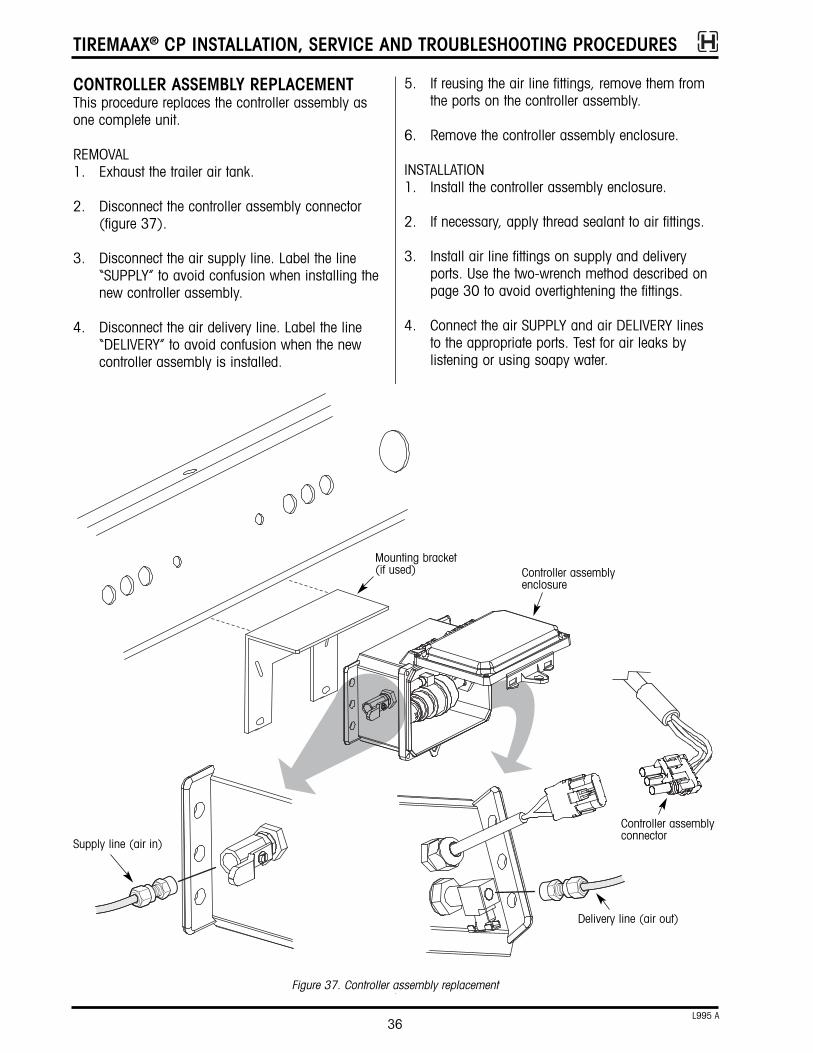
CONTROLLER ASSEMBLY REPLACEMENTThis procedure replaces the controller assembly asone complete unit.
REMOVAL1. Exhaust the trailer air tank.
2. Disconnect the controller assembly connector(figure 37).
3. Disconnect the air supply line. Label the line“SUPPLY” to avoid confusion when installing thenew controller assembly.
4. Disconnect the air delivery line. Label the line“DELIVERY” to avoid confusion when the newcontroller assembly is installed.
Figure 37. Controller assembly replacement
Controller assemblyconnector
Supply line (air in)
Delivery line (air out)
Controller assemblyenclosure
Mounting bracket(if used)
TIREMAAX® CP INSTALLATION, SERVICE AND TROUBLESHOOTING PROCEDURES
37L995 A
5. Connect the controller assembly connector.
6. Recharge the trailer air system.
7. Manually measure tire pressure. Refer to thesection titled Manually Checking Tire Pressure onpage 6 for complete manual tire pressuremeasuring instructions.
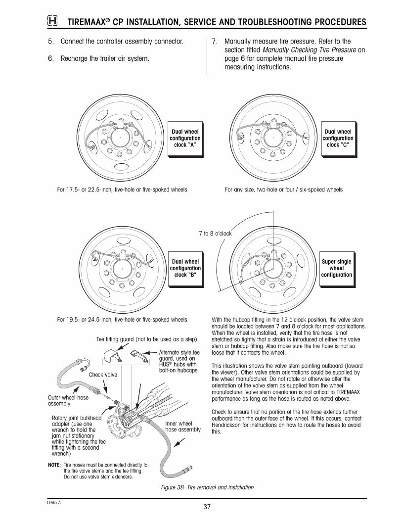
Figure 38. Tire removal and installation
Outer wheel hoseassembly
Check valve
Inner wheelhose assembly
Rotary joint bulkheadadapter (use onewrench to hold thejam nut stationarywhile tightening the teefitting with a secondwrench)
Tee fitting guard (not to be used as a step)
NOTE: Tire hoses must be connected directly tothe tire valve stems and the tee fitting.Do not use valve stem extenders.
Alternate style teeguard, used onHUS® hubs withbolt-on hubcaps
Dual wheelconfiguration clock “A”
For 17.5- or 22.5-inch, five-hole or five-spoked wheels
For 19.5- or 24.5-inch, five-hole or five-spoked wheels
For any size, two-hole or four / six-spoked wheels
7 to 8 o’clock
With the hubcap fitting in the 12 o'clock position, the valve stemshould be located between 7 and 8 o'clock for most applications.When the wheel is installed, verify that the tire hose is notstretched so tightly that a strain is introduced at either the valvestem or hubcap fitting. Also make sure the tire hose is not soloose that it contacts the wheel.
This illustration shows the valve stem pointing outboard (towardthe viewer). Other valve stem orientations could be supplied bythe wheel manufacturer. Do not rotate or otherwise alter the orientation of the valve stem as supplied from the wheelmanufacturer. Valve stem orientation is not critical to TIREMAAX performance as long as the hose is routed as noted above.
Check to ensure that no portion of the tire hose extends furtheroutboard than the outer face of the wheel. If this occurs, contactHendrickson for instructions on how to route the hoses to avoidthis.
Dual wheelconfiguration clock “C”
Dual wheelconfiguration clock “B”
Super singlewheel
configuration
TIREMAAX® CP INSTALLATION, SERVICE AND TROUBLESHOOTING PROCEDURES
38L995 A
6. If the tee fitting was removed, reinstall the teefitting and tighten the swivel threads to 130 ±10in. lbs. of torque. Refer to the TIRE HOSEINSTALLATION procedure on page 29 forcomplete tee fitting and tire hose tighteningdetails.
7. Reattach and firmly hand-tighten the tire hose(s)to the tee. Hand tightening will properly compressthe internal rubber gasket for an airtight sealwithout damaging the internal gasket. Refer tostep 5 of the TIRE HOSE INSTALLATION procedureon page 31 for complete tire hose to tee (orelbow) tightening details.
NOTE: Tire hoses must be connected directly to thetire valve stems and the tee fitting. Do not usevalve stem extenders.
8. Attach the tire hose(s) to the tire valve stem(s)and tighten finger tight.
9. Using a 7/16-inch wrench, tighten the tirehose/valve stem connection an additional one-half turn. Do not overtighten this connection.
10. If the tee fitting guard was removed, reinstall thetee fitting guard and tighten the hubcap bolts to12 - 18 ft. lbs. (16 - 24 N•m). Check all airsystem connections for leaks using the systemintegrity check found on page 32.
WHEEL-END SERVICE (HUB REMOVAL)When it is necessary to remove the hub, care must betaken to avoid damaging the rotary joint assembly:
• On HP and HUS® spindles (axles with same sizeinner and outer bearings), the hub may beremoved with the rotary joint in place. Follow theWHEEL REMOVAL AND INSTALLATION procedure onthis page to remove the wheel. Then remove thejam nut from the rotary joint bulkhead adapter andremove the hubcap. Finally, remove the hub. If necessary, refer to Hendrickson publication L496,Wheel-End Maintenance Procedures, for completehub removal details.
• To remove the hub on HN spindles, the rotary jointmust be detached from the spindle plug, but notcompletely removed from the braided axle hose.While detached from the spindle plug, the rotaryjoint can be moved, tipped or otherwise manipulated so the hub can clear it and be
8. Using the pressure adjustment procedure onpage 35, verify that the target tire pressurematches the desired operating tire pressure.
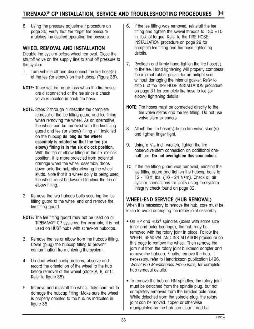
WHEEL REMOVAL AND INSTALLATIONDisable the system before wheel removal. Close theshutoff valve on the supply line to shut off pressure tothe system.
1. Turn vehicle off and disconnect the tire hose(s)at the tee (or elbow) on the hubcap (figure 38).
NOTE: There will be no air loss when the tire hosesare disconnected at the tee since a checkvalve is located in each tire hose.
NOTE: Steps 2 through 4 describe the completeremoval of the tee fitting guard and tee fittingwhen removing the wheel. As an alternative,the wheel can be removed with the tee fittingguard and tee (or elbow) fitting still installedon the hubcap as long as the wheelassembly is rotated so that the tee (orelbow) fitting is in the six o’clock position.With the tee or elbow fitting in the six o’clockposition, it is more protected from potentialdamage when the wheel assembly dropsdown onto the hub after clearing the wheelstuds. Note that if a wheel dolly is being used,the wheel must be lowered to clear the tee orelbow fitting.
2. Remove the two hubcap bolts securing the teefitting guard to the wheel end and remove the tee fitting guard.
NOTE: The tee fitting guard may not be used on allTIREMAAX® CP systems. For example, it is notused on HUS® hubs with screw-on hubcaps.
3. Remove the tee or elbow from the hubcap fitting.Cover (plug) the hubcap fitting to preventcontamination from entering the system.
4. On dual-wheel configurations, observe andrecord the orientation of the wheel to the hubbefore removal of the wheel (clock A, B, or C.Refer to figure 38).
5. Remove and reinstall the wheel. Take care not todamage the hubcap fitting. Make sure the wheelis properly oriented to the hub as indicated infigure 38.

TIREMAAX® CP INSTALLATION, SERVICE AND TROUBLESHOOTING PROCEDURES
39L995 A
2. Rotate the rotary joint exit tube one fullrevolution. Make sure that the steel air tube doesnot contact any part of the spindle or spindle nutsystem.
HUBCAP ASSEMBLY1. Place hubcap gasket over rotary joint exit tube
and bulkhead adapter.
2. Lubricate O-ring on the rotary joint bulkheadadapter. Use the same lubricant as is used in thehub or a light film of #2 grease, white lithiumgrease or Vaseline®.
3. From the inside, insert the bulkhead adapterthrough the hole in the hubcap labeled “Air”. Alignthe flat on the bulkhead adapter with the anti-rotation flat in the hubcap (figure 18). Note theorientation indicator on the top of the bulkheadadapter threads (figure 18, view a). Use thisindicator (some models have a dot, other modelshave a notch) to properly orient the bulkheadadapter in the hubcap hole. When the flat on thebulkhead adapter is properly aligned with theanti-rotation flat in the hubcap, the orientationindicator will face outboard (figure 18, view b).
Do not use pliers or any kind of wrench to pullthe bulkhead adapter up through the hole in thehubcap. This could cause the bulkhead adapterto rotate before it engages the flat in thehubcap, potentially damaging the rotary unionor hubcap.
Attach the jam nut and hand tighten. Whenproperly seated, the top of the bulkhead adapter
removed. There is no need to disconnect the rotaryjoint from the braided axle hose. Follow the WHEELREMOVAL AND INSTALLATION procedure on the previous page to remove the wheel, then use thefollowing procedure to detach the rotary joint forhub removal.
ROTARY JOINT DETACHMENT (FOR HUBREMOVAL ON HN SPINDLES)1. Remove the jam nut from the rotary joint bulk-
head adapter and remove the hubcap (figure 39).
2. Remove the three fasteners holding the rotaryjoint assembly to the spindle plug (figure 40).
3. When detached, the rotary joint can be moved,tipped or otherwise manipulated so the spindlenuts, outer bearing and hub can clear the rotaryjoint and be removed. DO NOT disconnect therotary joint from the braided axle hose.
ROTARY JOINT REATTACHMENT1. When hub / wheel-end service is complete, re-
attach the rotary joint to the spindle plug byinstalling the three T20 Torx fasteners andtightening to 45 ±5 in. lbs. (5 ±½ N•m) oftorque.
figure 39. Hubcap to bulkhead adapter removal
Rotary joint assembly
Hubcap
Jam nut
Bulkheadadapter
Spindle
figure 40. Rotary joint removal from spindle
T20 Torxfasteners

TIREMAAX® CP INSTALLATION, SERVICE AND TROUBLESHOOTING PROCEDURES
40L995 A
will be flush (or higher) with the top of the jamnut when hand tightened (figure 18, view c).
CAUTION: Wheel must be properly “clocked” tothe hubcap to prevent the hosesfrom rubbing on the wheel (figure29). Failure to properly “clock” thewheels may result in hose failure.
4. Install the hubcap. If the hubcap is a screw-onstyle used on the HUS hub, tighten it to 50-100ft. lbs. (68-137 N•m) of torque. If the hubcap isa bolt-on style used on the other hubs, tightenthe hubcap bolts to 12-18 ft. lbs. (16-24 N•m)of torque.
5. Tighten the rotary joint jam nut to 15 ft. lbs. (20 N•m) of torque.
6. Refer to the TIRE HOSE INSTALLATION section onpage 29 to complete the reassembly.
GLOSSARYTIREMAAX® CP Tire Inflation System — A systemthat maintains the pressure of selected tires and activates a warning to alert the vehicle operator ifthere is a system or tire leak.
Integrated Pressure Control Unit (IPCU) — The IPCUis programmed with the target tire pressure anddirects the system to supply air to the tires whenneeded. A significant amount of system air flowcauses the trailer-mounted indicator to illuminate.
Rotary Joint — Rotary air seal assembly that allowsair transfer from wheel end to tire(s) while vehicle isin motion. The rotary joint is always pressurizedwhen the shutoff valve is open.
Target Tire Pressure — The desired tire pressure.
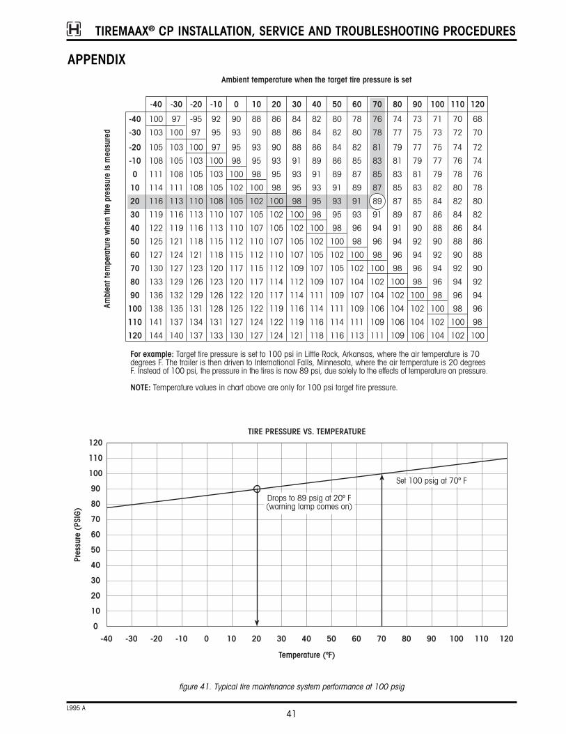
TIREMAAX® CP INSTALLATION, SERVICE AND TROUBLESHOOTING PROCEDURES
41L995 A
APPENDIX
figure 41. Typical tire maintenance system performance at 100 psig
Ambient temperature when the target tire pressure is set
For example: Target tire pressure is set to 100 psi in Little Rock, Arkansas, where the air temperature is 70degrees F. The trailer is then driven to International Falls, Minnesota, where the air temperature is 20 degreesF. Instead of 100 psi, the pressure in the tires is now 89 psi, due solely to the effects of temperature on pressure.
-40 -30 -20 -10 0 10 20 30 40 50 60 70 80 90 100 110 120
120
110
100
90
80
70
60
50
40
30
20
10
0
TIRE PRESSURE VS. TEMPERATURE
Temperature (ºF)
Pres
sure
(PS
IG)
Drops to 89 psig at 20º F(warning lamp comes on)
Set 100 psig at 70º F
68
70
72
74
76
78
80
82
84
86
88
90
92
94
96
98
100
120
70
72
74
76
78
80
82
84
86
88
90
92
94
96
98
100
102
110
71
73
75
77
79
82
84
86
88
90
92
94
96
98
100
102
104
100
74
77
79
81
83
85
87
89
91
94
96
98
100
102
104
106
109
80
76
78
81
83
85
87
89
91
94
96
98
100
102
104
106
109
111
70
78
80
82
85
87
89
91
93
96
98
100
102
104
107
109
111
113
60
80
82
84
86
89
91
93
95
98
100
102
105
107
109
111
114
116
50
100
103
105
108
111
114
116
119
122
125
127
130
133
136
138
141
144
-40
-40
-30
-20
-10
0
10
20
30
40
50
60
70
80
90
100
110
120
97
100
103
105
108
111
113
116
119
121
124
127
129
132
135
137
140
-30
-95
97
100
103
105
108
110
113
116
118
121
123
126
129
131
134
137
-20
92
95
97
100
103
105
108
110
113
115
118
120
123
126
128
131
133
-10
90
93
95
98
100
102
105
107
110
112
115
117
120
122
125
127
130
0
88
90
93
95
98
100
102
105
107
110
112
115
117
120
122
124
127
10
86
88
90
93
95
98
100
102
105
107
110
112
114
117
119
122
124
20
84
86
88
91
93
95
98
100
102
105
107
109
112
114
116
119
121
30
82
84
86
89
91
93
95
98
100
102
105
107
109
111
114
116
118
40
73
75
77
79
81
83
85
87
90
92
94
96
98
100
102
104
106
90Am
bien
t tem
pera
ture
whe
n tir
e pr
essu
re is
mea
sure
d
NOTE: Temperature values in chart above are only for 100 psi target tire pressure.

TIREMAAX® CP INSTALLATION, SERVICE AND TROUBLESHOOTING PROCEDURES
42L995 A

TIREMAAX® CP INSTALLATION, SERVICE AND TROUBLESHOOTING PROCEDURES
43L995 A

www.hendrickson-intl.com
Information contained in this literature was accurate at the time of publication. Product changes may have been made after the copyright date that are not reflected.© 2012 Hendrickson USA, L.L.C. (U.S. Rights) Hendrickson International Corporation (Rights Outside U.S.) All Rights ReservedL995 Rev A 02-12 ECN 20456
Hendrickson Canada250 Chrysler Drive, Unit #3Brampton, ON Canada L6S 6B6 905.789.1030Fax 905.789.1033
Hendrickson MexicanaAv. Industria Automotriz #200Parque Industrial Stiva AeropuertoApodaca, N.L., México C.P. 66600 +52 (81) 8288 1300Fax +52 (81) 8288 1301
Trailer Commercial Vehicle systems2070 Industrial Place SECanton, OH 44707-2641 USA
866.RIDEAIR (743.3247)330.489.0045Fax 800.696.4416
Printed in United States of America