tinyhive: dynamic virtual machine for...
TRANSCRIPT
TINYHIVE: DYNAMIC VIRTUAL MACHINE FOR
SENSOR NETWORKS
By
MANISH REGMI
Bachelor of Engineering in Information Technology
Pokhara University
Nepal
2005
Submitted to the Faculty of the Graduate College of the
Oklahoma State University in partial fulfillment of the requirements for
the Degree of MASTER OF SCIENCE
December, 2009
ii
TINYHIVE: DYNAMIC VIRTUAL MACHINE FOR
SENSOR NETWORKS
Thesis Approved:
Dr. Xiaolin Li
Thesis Adviser
Dr. Johnson Thomas
Dr. Subhash Kak
Dr. A. Gordon Emslie
Dean of the Graduate College
iii
ACKNOWLEDGMENTS
First of all I would like to acknowledge Dr. Xiaolin Li for giving me an opportunity to
work with him. Without his continuous support I would not have been succeeded in this
research. I would like to thank him very much for all the support he has provided and the
guidance he has given.
I would also like to thank all the members of the S3lab for their support. I would also like
to thank my colleagues Xinxin, Aayesha, and Praveen for helping me out with the
project. I would also like to thank all my friends for their support.
And above all I would like to thank my mom and dad for everything they have done for me.

iv
TABLE OF CONTENTS
Chapter Page I. INTRODUCTION ......................................................................................................1
1.1 OUR CONTRIBUTIONS ..................................................................................4 1.2 OUTLINE OF THE THESIS .............................................................................4 II. REVIEW OF LITERATURE....................................................................................4
2.1 DELUGE............................................................................................................4 2.2 TINYDB ............................................................................................................4
2.3 MATE ................................................................................................................6 2.4 SWISSQM .........................................................................................................7 2.5 SOS ....................................................................................................................8 III. METHODOLOGY ................................................................................................11 3.1 ARCHITECTURE ...........................................................................................11 3.2 DATA STRUCTURES ....................................................................................16 3.3 MEMORY MANAGEMENT ..........................................................................18 3.4 INSTRUCTION SET ARCHITECTURE .......................................................19 3.5 VIRTUAL CODE INTERPRETER ................................................................26 3.6 DYNAMIC INSTRUCTIONS.........................................................................26
IV. FINDINGS .............................................................................................................30 4.1 INTRODUCTION ...........................................................................................30 4.2 CASE STUDY 1: SIMPLE VIRTUAL APPLICATION ................................31 4.3 CASE STUDY 2: DYNAMIC INSTRUCTION .............................................34 4.3 CASE STUDY 3: REAL WORLD EXAMPLE ..............................................35 4.5 ENERGY USAGE ANALYSIS ......................................................................36
v
Chapter Page
V. CONCLUSION AND FUTURE WORK ..............................................................38 REFERENCES ............................................................................................................40 APPENDIX A: MANUAL ..........................................................................................44 APPENDIX B: SOURCE CODES ..............................................................................46
vi
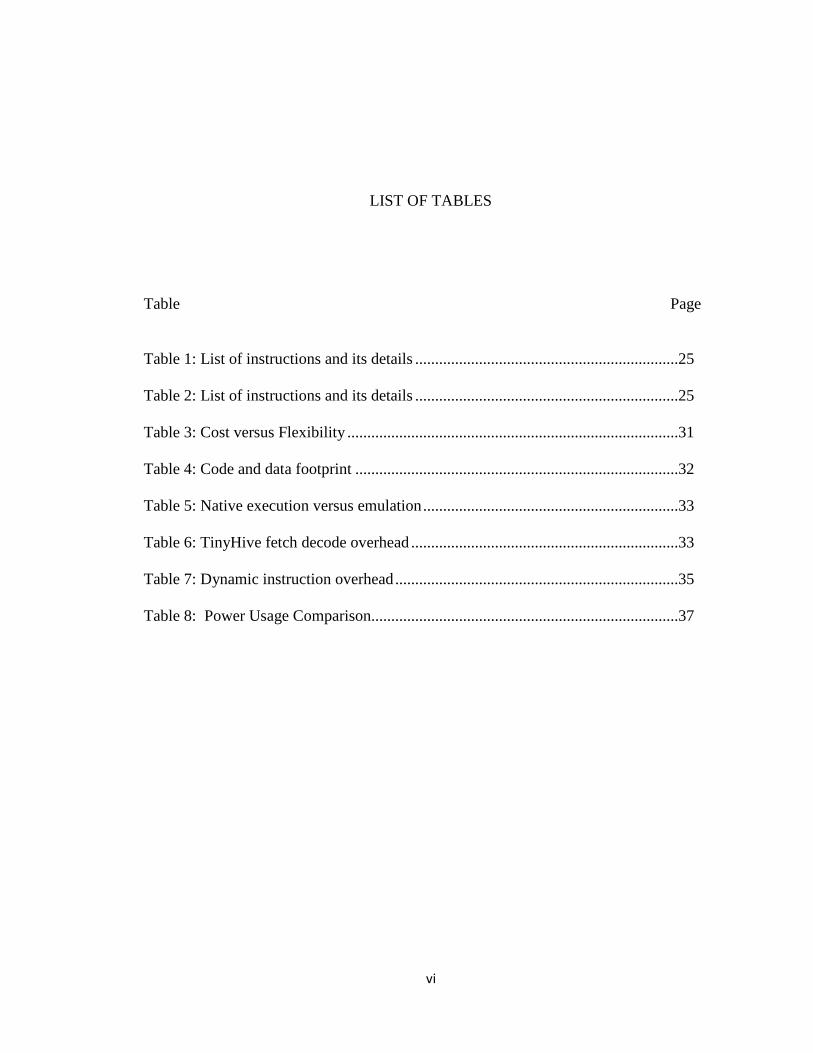
LIST OF TABLES
Table Page
Table 1: List of instructions and its details ..................................................................25
Table 2: List of instructions and its details ..................................................................25
Table 3: Cost versus Flexibility ...................................................................................31
Table 4: Code and data footprint .................................................................................32
Table 5: Native execution versus emulation ................................................................33
Table 6: TinyHive fetch decode overhead ...................................................................33
Table 7: Dynamic instruction overhead .......................................................................35
Table 8: Power Usage Comparison.............................................................................37
vii
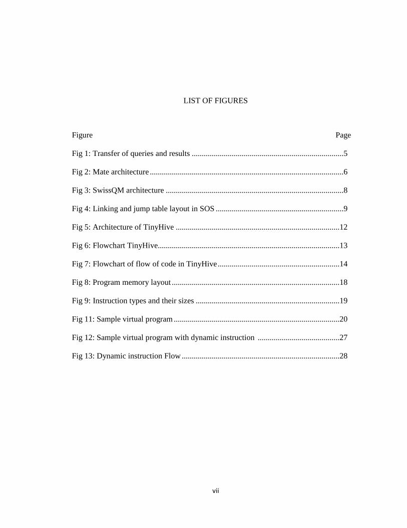
LIST OF FIGURES
Figure Page Fig 1: Transfer of queries and results ............................................................................5
Fig 2: Mate architecture .................................................................................................6
Fig 3: SwissQM architecture .........................................................................................8
Fig 4: Linking and jump table layout in SOS ................................................................9
Fig 5: Architecture of TinyHive ..................................................................................12
Fig 6: Flowchart TinyHive...........................................................................................13
Fig 7: Flowchart of flow of code in TinyHive .............................................................14
Fig 8: Program memory layout ....................................................................................18
Fig 9: Instruction types and their sizes ........................................................................19
Fig 11: Sample virtual program ...................................................................................20
Fig 12: Sample virtual program with dynamic instruction .........................................27 Fig 13: Dynamic instruction Flow ...............................................................................28
1
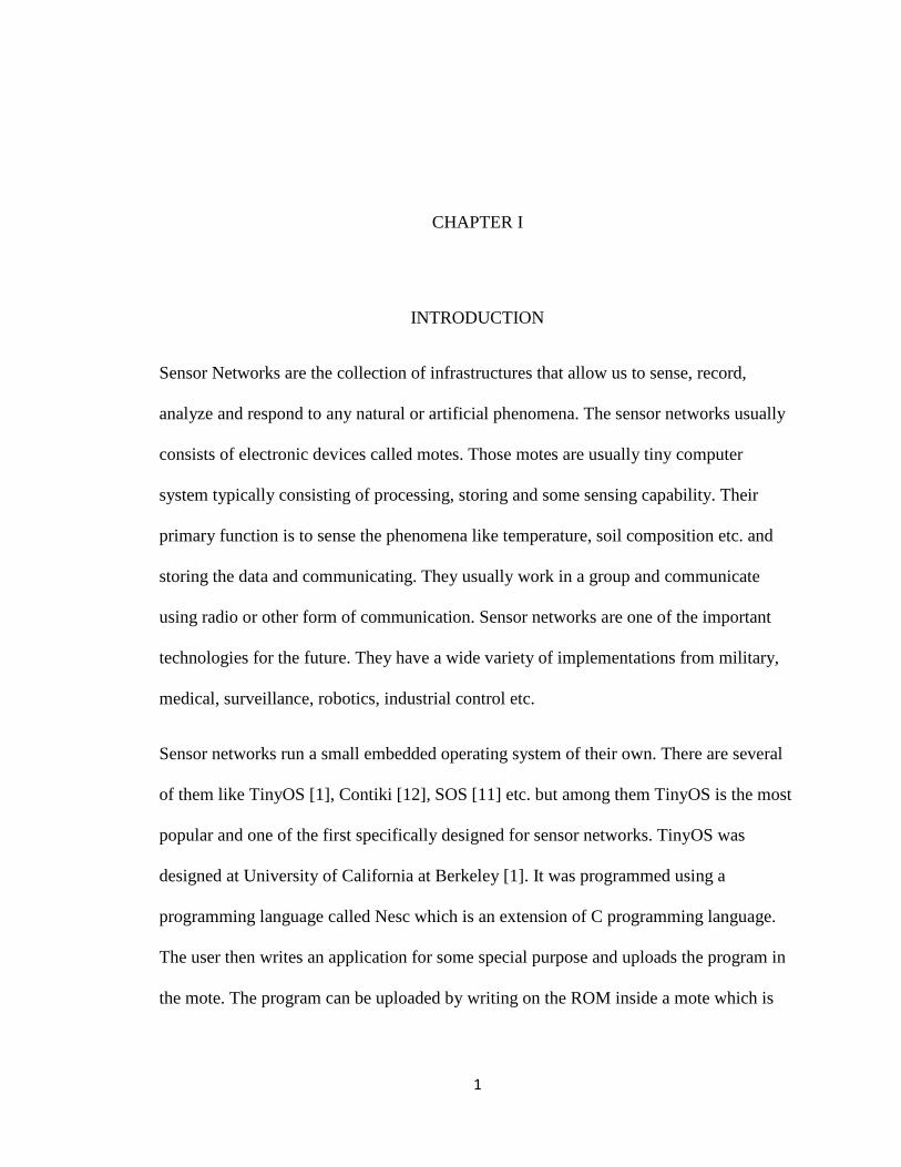
CHAPTER I
INTRODUCTION
Sensor Networks are the collection of infrastructures that allow us to sense, record,
analyze and respond to any natural or artificial phenomena. The sensor networks usually
consists of electronic devices called motes. Those motes are usually tiny computer
system typically consisting of processing, storing and some sensing capability. Their
primary function is to sense the phenomena like temperature, soil composition etc. and
storing the data and communicating. They usually work in a group and communicate
using radio or other form of communication. Sensor networks are one of the important
technologies for the future. They have a wide variety of implementations from military,
medical, surveillance, robotics, industrial control etc.
Sensor networks run a small embedded operating system of their own. There are several
of them like TinyOS [1], Contiki [12], SOS [11] etc. but among them TinyOS is the most
popular and one of the first specifically designed for sensor networks. TinyOS was
designed at University of California at Berkeley [1]. It was programmed using a
programming language called Nesc which is an extension of C programming language.
The user then writes an application for some special purpose and uploads the program in
the mote. The program can be uploaded by writing on the ROM inside a mote which is
2
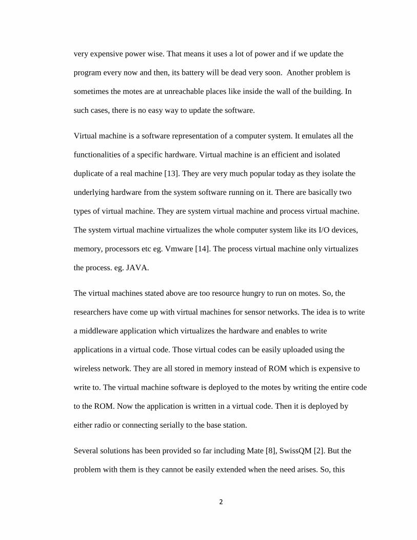
very expensive power wise. That means it uses a lot of power and if we update the
program every now and then, its battery will be dead very soon. Another problem is
sometimes the motes are at unreachable places like inside the wall of the building. In
such cases, there is no easy way to update the software.
Virtual machine is a software representation of a computer system. It emulates all the
functionalities of a specific hardware. Virtual machine is an efficient and isolated
duplicate of a real machine [13]. They are very much popular today as they isolate the
underlying hardware from the system software running on it. There are basically two
types of virtual machine. They are system virtual machine and process virtual machine.
The system virtual machine virtualizes the whole computer system like its I/O devices,
memory, processors etc eg. Vmware [14]. The process virtual machine only virtualizes
the process. eg. JAVA.
The virtual machines stated above are too resource hungry to run on motes. So, the
researchers have come up with virtual machines for sensor networks. The idea is to write
a middleware application which virtualizes the hardware and enables to write
applications in a virtual code. Those virtual codes can be easily uploaded using the
wireless network. They are all stored in memory instead of ROM which is expensive to
write to. The virtual machine software is deployed to the motes by writing the entire code
to the ROM. Now the application is written in a virtual code. Then it is deployed by
either radio or connecting serially to the base station.
Several solutions has been provided so far including Mate [8], SwissQM [2]. But the
problem with them is they cannot be easily extended when the need arises. So, this
3
research tries to make a virtual machine which is extendible. This enables the
applications to extend the functionality without having to redeploy the whole system.
So, the finding of this research could be very helpful for the development of
sensor network applications and its deployment.
1. OUR CONTRIBUTIONS
• The User will be able to define his own instruction and implement his own
handler code for his instruction.
• It will make the applications more flexible and will be able to do things the
traditional virtual machines could not.
• It will consume less power than deluge because it writes only a portion of code
memory.
2. OUTLINE OF THE THESIS
• The introduction part introduces in brief the idea about sensor networks, virtual
machines and its relationship.
• In the review of literature, we talk about the various systems that were created to
make mote reprogramming more convenient. Those systems include Deluge,
TinyDB, Mate, SwissQM and SOS.
4
• In the Methodology section, we talk about how the TinyHIve system is designed.
It describes about architecture, data structures, memory management, instruction
set architecture, virtual code interpreter and dynamic instructions.
• In the Findings section, we describe the three test cases we used to test the
TinyHive system. We also present some code performance analysis.
• In the conclusion and future work section, we talk about the contributions of the
TinyHive and also talk about how it can be improved.
5
CHAPTER II
REVIEW OF LITERATURE
The virtual machine for sensor network is a very promising topic. So, several works has
been done in the field of virtual machine for sensor networks.
2.1. DELUGE
One of the earlier implementation was Deluge [5]. It is not a virtual machine but a
middleware application that allows sending binaries using a wireless network. The deluge
middleware receives the incoming network data and writes the new program to memory.
Though this technique does not require us to be physically present for reprogramming,
the overhead of reprogramming is still there. It just sends the application binary over the
network but the reprogramming still has to be done. And that process takes a lot of
power.
2.2. TINYDB
Another implementation that is designed to overcome the shortcoming mentioned above
is TinyDB[7]. TinyDB makes possible to write a sensor network application in a form
6
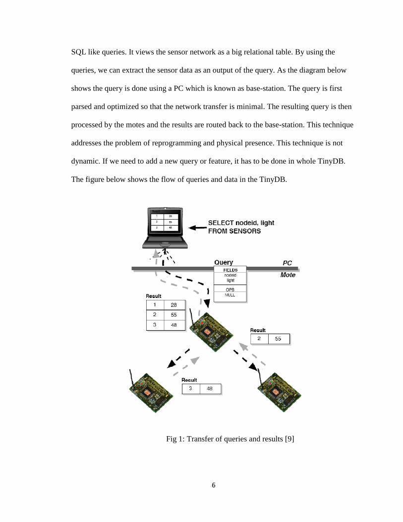
SQL like queries. It views the sensor network as a big relational table. By using the
queries, we can extract the sensor data as an output of the query. As the diagram below
shows the query is done using a PC which is known as base-station. The query is first
parsed and optimized so that the network transfer is minimal. The resulting query is then
processed by the motes and the results are routed back to the base-station. This technique
addresses the problem of reprogramming and physical presence. This technique is not
dynamic. If we need to add a new query or feature, it has to be done in whole TinyDB.
The figure below shows the flow of queries and data in the TinyDB.
Fig 1: Transfer of queries and results [9]
7
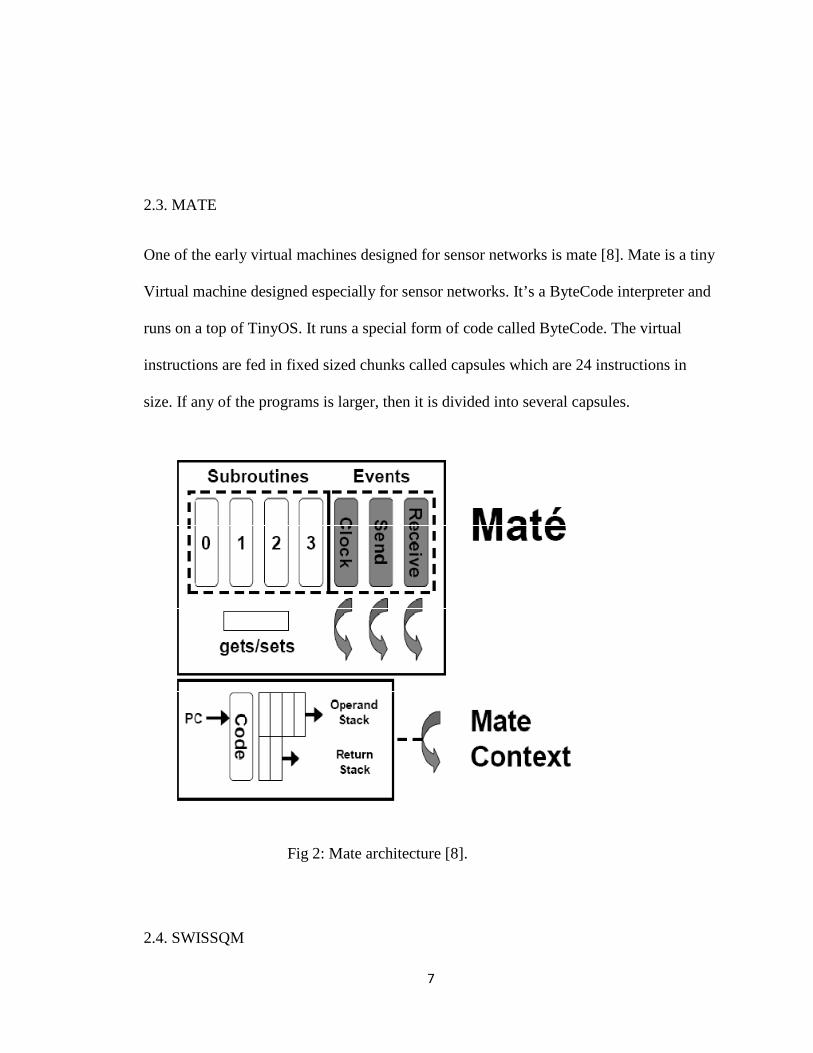
2.3. MATE
One of the early virtual machines designed for sensor networks is mate [8]. Mate is a tiny
Virtual machine designed especially for sensor networks. It’s a ByteCode interpreter and
runs on a top of TinyOS. It runs a special form of code called ByteCode. The virtual
instructions are fed in fixed sized chunks called capsules which are 24 instructions in
size. If any of the programs is larger, then it is divided into several capsules.
Fig 2: Mate architecture [8].
2.4. SWISSQM
8
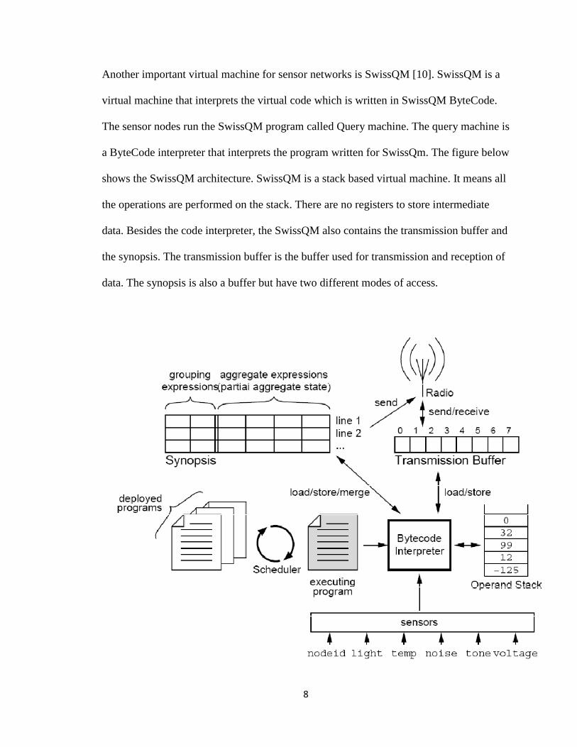
Another important virtual machine for sensor networks is SwissQM [10]. SwissQM is a
virtual machine that interprets the virtual code which is written in SwissQM ByteCode.
The sensor nodes run the SwissQM program called Query machine. The query machine is
a ByteCode interpreter that interprets the program written for SwissQm. The figure below
shows the SwissQM architecture. SwissQM is a stack based virtual machine. It means all
the operations are performed on the stack. There are no registers to store intermediate
data. Besides the code interpreter, the SwissQM also contains the transmission buffer and
the synopsis. The transmission buffer is the buffer used for transmission and reception of
data. The synopsis is also a buffer but have two different modes of access.
9
Fig 3: SwissQM architecture [10]
The SwissQM virtual machine also contains the gateway program. It runs on a base
station and is also used to generate the ByteCode and feed the ByteCode to the motes.
2.5. SOS
SOS [11] is an operating system designed for sensor networks. It was written in C
programming language. The main distinction of SOS from other sensor network based
operating system is that it is dynamic in nature. It means the functionality of the operating
system can be increased by using pluggable modules. The modules, which are written by
users, can be deployed at runtime. This implementation closely resembles Microkernel
architecture [15].
10
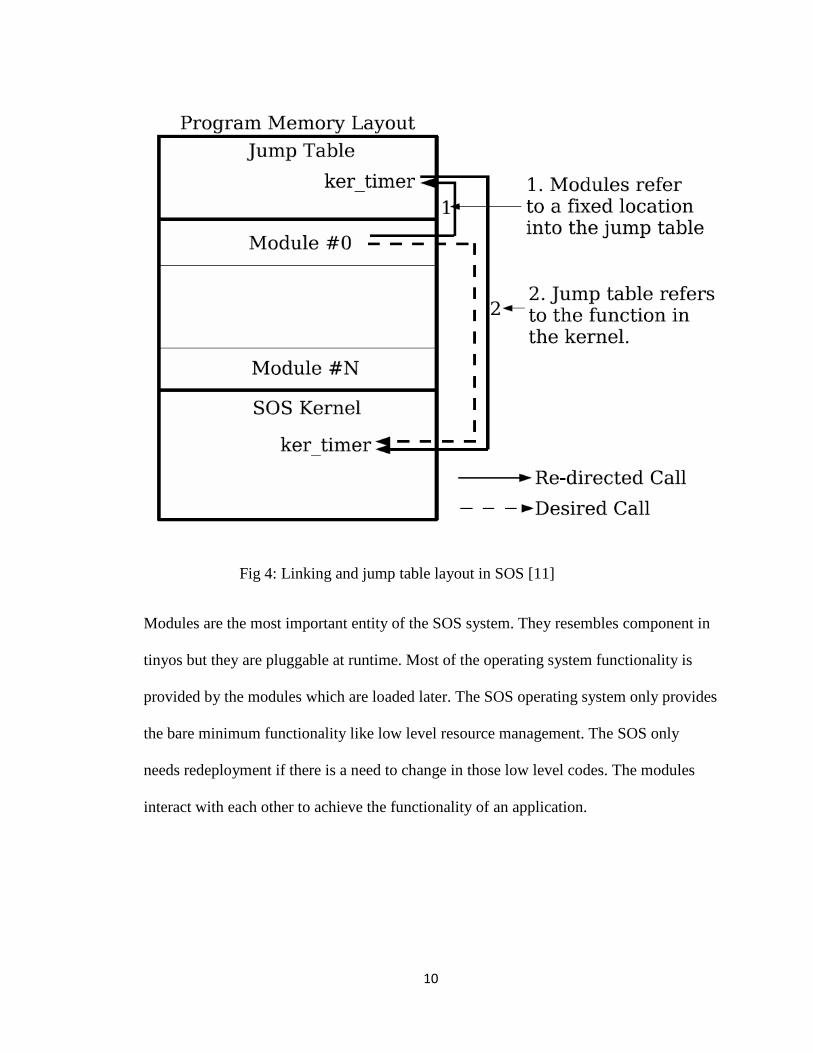
Fig 4: Linking and jump table layout in SOS [11]
Modules are the most important entity of the SOS system. They resembles component in
tinyos but they are pluggable at runtime. Most of the operating system functionality is
provided by the modules which are loaded later. The SOS operating system only provides
the bare minimum functionality like low level resource management. The SOS only
needs redeployment if there is a need to change in those low level codes. The modules
interact with each other to achieve the functionality of an application.
11
CHAPTER III
METHODOLOGY
Virtual machine for sensor networks is becoming a very popular research topic these
days. The research was started first by designing a very simple virtual machine. It was
then further extended by implementing a feature of dynamic instructions where users can
define and implement their own instruction set. This project shall now be referred as
TinyHive. The main components of the TinyHive are Instruction sets, virtual code
interpreter and memory manager.
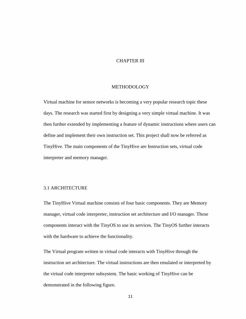
3.1 ARCHITECTURE
The TinyHive Virtual machine consists of four basic components. They are Memory
manager, virtual code interpreter, instruction set architecture and I/O manager. Those
components interact with the TinyOS to use its services. The TinyOS further interacts
with the hardware to achieve the functionality.
The Virtual program written in virtual code interacts with TinyHive through the
instruction set architecture. The virtual instructions are then emulated or interpreted by
the virtual code interpreter subsystem. The basic working of TinyHive can be
demonstrated in the following figure.
12
Fig 5: Architecture of TinyHive
As the above figure shows, the virtual program interacts with TinyHive which interacts
with TinyOS and which interacts with the underlying hardware.
There are several ways to implement a virtual machine. One technique is to use the
intermediate registers to hold the intermediate data and the other is to use the stack for the
operands and intermediate data. The latter is called stack based virtual machine.
TinyHive is a stack based virtual machine. All the operations are done in stack. There are
no intermediate registers to store the results. For example to do a simple addition of
a = b + c, we do
Push b
Push c
Virtual
Program
Virtual
Program
Virtual
Program
Tiny OS
Instruction Set Architecture
Virtual Code
Interpreter
Memory Manager
I/O
Manager
Mote Hardware
13
Add
Pop a
The reason for using the stack based virtual machine is that it makes the code compact
and we don’t have to use separate instructions to move data to register and so on. So, the
implementation of TinyHive consists of a dedicated stack space for instruction execution.
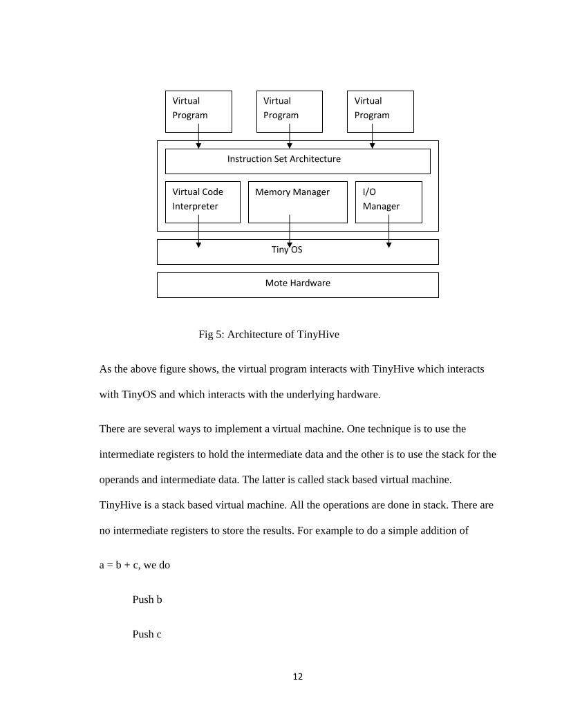
The flowchart below shows the flow of program in TinyHive.
Fig 6: Flowchart TinyHive
Start
Initialize
Dispatch_program
Check
availability
Run_program
return
Init_program Radio/serial handler
New
program data
14
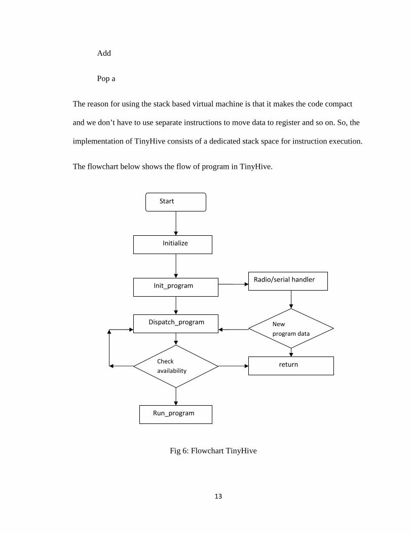
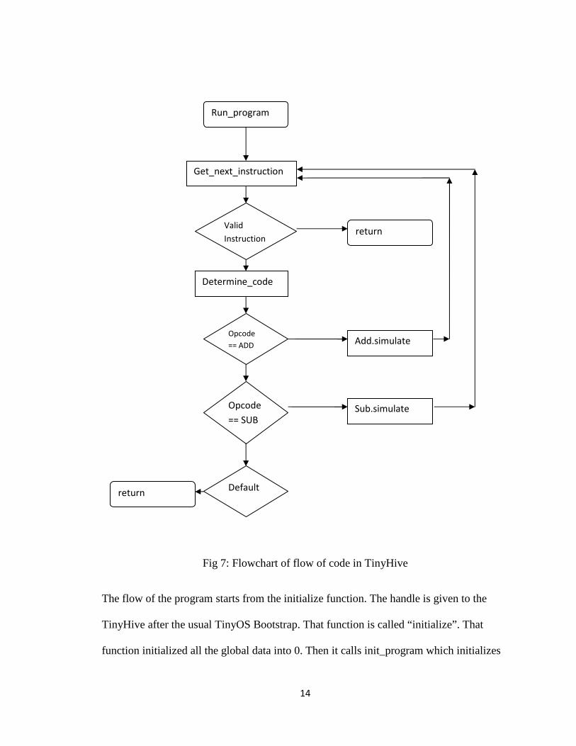
Fig 7: Flowchart of flow of code in TinyHive
The flow of the program starts from the initialize function. The handle is given to the
TinyHive after the usual TinyOS Bootstrap. That function is called “initialize”. That
function initialized all the global data into 0. Then it calls init_program which initializes
Run_program
Get_next_instruction
Valid
Instruction
Determine_code
Opcode
== SUB
Opcode
== ADD
Default return
return
Sub.simulate
Add.simulate
15
the stack and memory for program. Then dispatch_program is called, which checks if
there are any virtual program loaded in memory. If it finds the program, then it calls the
run_program function. It gets the virtual instruction one by one and executes it. The
instruction with opcode 0x00 is considered as the end of program. If it encounters
instruction not defined it is considered illegal instruction and is terminated. The program
waits in the loop until another program is found. The programs are uploaded using radio
or serial communication. The handler for radio and serial loads the incoming program
into the memory and its returns. The dispatch_program detects it and runs the new
program.
Besides the normal instructions, there a special instruction called the “dyninst”. It’s a
dynamic instruction. The purpose of the instruction is to create a new user defined
instruction which can later be used by other applications. A typical example of this is a
customized mote hardware which is customized to get soil sensor data. If the user
application has to run in a virtual machine environment, there is no virtual instruction to
read the sensor data. In TinyHive, the developer can add a new instruction that reads the
sensor data. All other applications can then use that instruction. To accomplish this
behavior, the “dyninst” instruction should be able to upload the machine instruction to
accomplish that behavior and store it in program memory so that in can be run. So the
handler of the instruction should be able to find the free space in the program memory
and write the handler code to that space. TinyHive should also keep track of the new
virtual instructions added and its location, size, etc.
Now when the newly created instruction is used by the virtual application, the tinyhive
interpreter determines it as a dynamic instruction and jumps the program to the location
16
where its code was written in program memory. After the code is executed it returns
back.
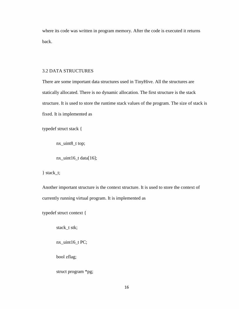
3.2 DATA STRUCTURES
There are some important data structures used in TinyHive. All the structures are
statically allocated. There is no dynamic allocation. The first structure is the stack
structure. It is used to store the runtime stack values of the program. The size of stack is
fixed. It is implemented as
typedef struct stack {
nx_uint8_t top;
nx_uint16_t data[16];
} stack_t;
Another important structure is the context structure. It is used to store the context of
currently running virtual program. It is implemented as
typedef struct context {
stack_t stk;
nx_uint16_t PC;
bool zflag;
struct program *pg;
17
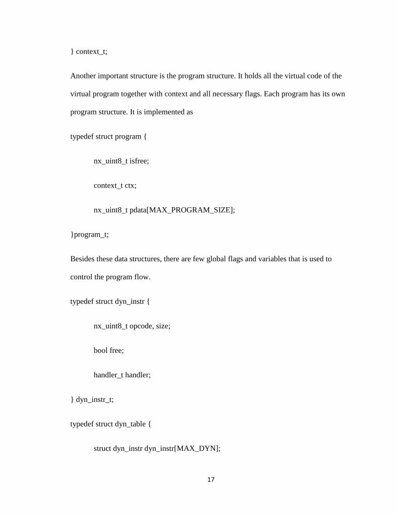
} context_t;
Another important structure is the program structure. It holds all the virtual code of the
virtual program together with context and all necessary flags. Each program has its own
program structure. It is implemented as
typedef struct program {
nx_uint8_t isfree;
context_t ctx;
nx_uint8_t pdata[MAX_PROGRAM_SIZE];
}program_t;
Besides these data structures, there are few global flags and variables that is used to
control the program flow.
typedef struct dyn_instr {
nx_uint8_t opcode, size;
bool free;
handler_t handler;
} dyn_instr_t;
typedef struct dyn_table {
struct dyn_instr dyn_instr[MAX_DYN];
18
} dyn_table_t;
The dyn_table data structure is used to store the information about the new instructions
that are dynamically loaded. The total number of new instructions supported is
determined by MAX_DYN. Each new instruction has its opcode, handler size and the
function pointer to the handler of the function.
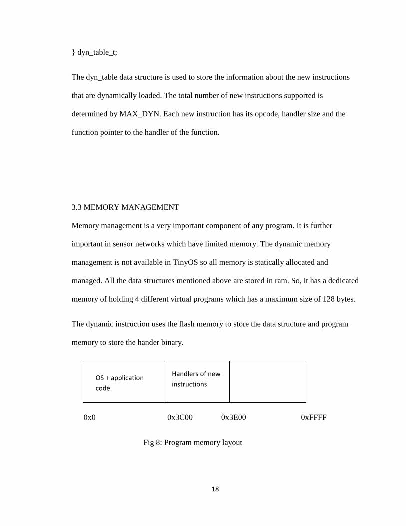
3.3 MEMORY MANAGEMENT
Memory management is a very important component of any program. It is further
important in sensor networks which have limited memory. The dynamic memory
management is not available in TinyOS so all memory is statically allocated and
managed. All the data structures mentioned above are stored in ram. So, it has a dedicated
memory of holding 4 different virtual programs which has a maximum size of 128 bytes.
The dynamic instruction uses the flash memory to store the data structure and program
memory to store the hander binary.
0x0 0x3C00 0x3E00 0xFFFF
Fig 8: Program memory layout
OS + application
code
Handlers of new
instructions
19
3.4 INSTRUCTION SET ARCHITECTURE
Instruction sets are the bases of all computer systems. The virtual machine also resembles
a physical computer system. So it must have its own instruction set.
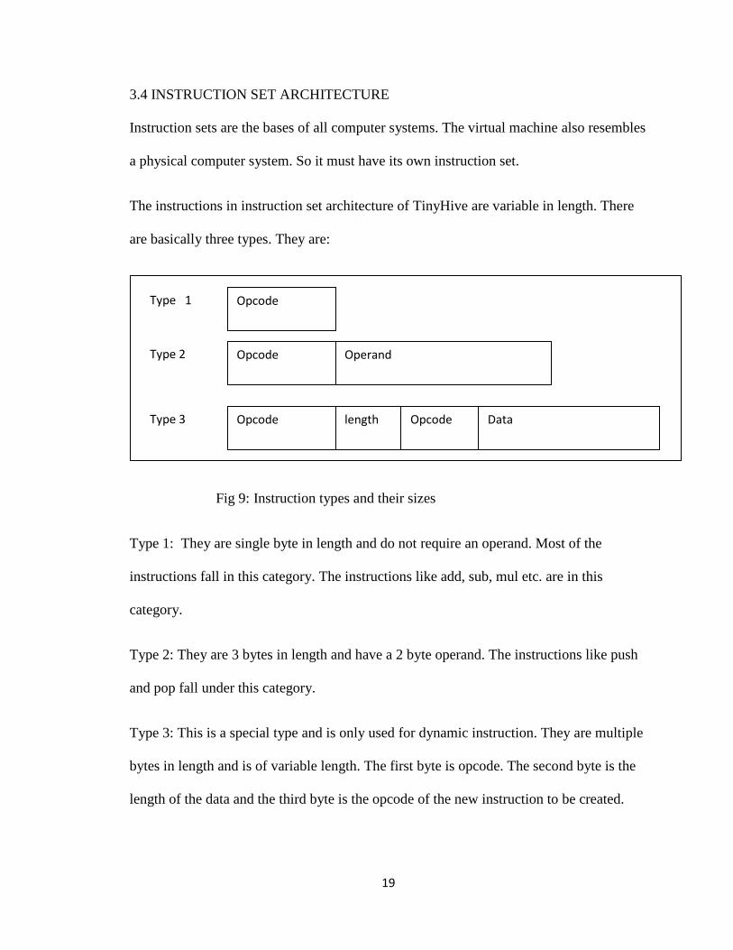
The instructions in instruction set architecture of TinyHive are variable in length. There
are basically three types. They are:
Fig 9: Instruction types and their sizes
Type 1: They are single byte in length and do not require an operand. Most of the
instructions fall in this category. The instructions like add, sub, mul etc. are in this
category.
Type 2: They are 3 bytes in length and have a 2 byte operand. The instructions like push
and pop fall under this category.
Type 3: This is a special type and is only used for dynamic instruction. They are multiple
bytes in length and is of variable length. The first byte is opcode. The second byte is the
length of the data and the third byte is the opcode of the new instruction to be created.
Opcode
(1 byte)
Opcode
(1 byte)
Operand
(2 bytes)
Type 1
Type 2
Opcode
(1 byte)
length
(1 byte)
Data
(Multibyte)
Type 3 Opcode
(1 byte)
20
The rest of the bytes are the machine codes that are to be executed as the microcode of
the newly created instruction.
There are only a couple of instructions that have operands and they are push, pop and
dyninst. Other instructions do not require the operands because all the operands are
available in the stack through the push and pop instructions. The instruction set and thus
the program is fed to the interpreter in its binary form. This makes the program compact
and easy to process. The current implement encodes the instruction in an 8 bit (1 byte)
value and the operand as a 16 bit value except for dyninst for which operand is multibyte.
So the binary program consists of an array of 1 byte and 3 bytes data. The interpreter
determines whether the next byte is an instruction or operand by looking at the
instruction. The instructions have specific numbers it matches the numbers and finds out
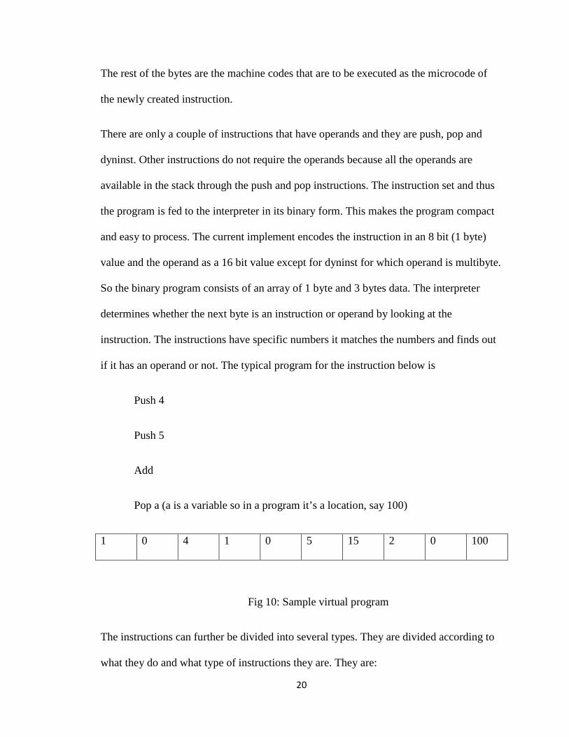
if it has an operand or not. The typical program for the instruction below is
Push 4
Push 5
Add
Pop a (a is a variable so in a program it’s a location, say 100)
1 0 4 1 0 5 15 2 0 100
Fig 10: Sample virtual program
The instructions can further be divided into several types. They are divided according to
what they do and what type of instructions they are. They are:
21
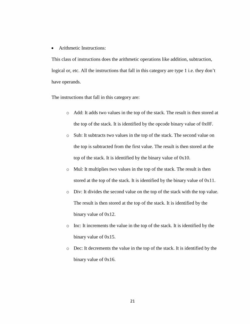
• Arithmetic Instructions:
This class of instructions does the arithmetic operations like addition, subtraction,
logical or, etc. All the instructions that fall in this category are type 1 i.e. they don’t
have operands.
The instructions that fall in this category are:
o Add: It adds two values in the top of the stack. The result is then stored at
the top of the stack. It is identified by the opcode binary value of 0x0F.
o Sub: It subtracts two values in the top of the stack. The second value on
the top is subtracted from the first value. The result is then stored at the
top of the stack. It is identified by the binary value of 0x10.
o Mul: It multiplies two values in the top of the stack. The result is then
stored at the top of the stack. It is identified by the binary value of 0x11.
o Div: It divides the second value on the top of the stack with the top value.
The result is then stored at the top of the stack. It is identified by the
binary value of 0x12.
o Inc: It increments the value in the top of the stack. It is identified by the
binary value of 0x15.
o Dec: It decrements the value in the top of the stack. It is identified by the
binary value of 0x16.
22
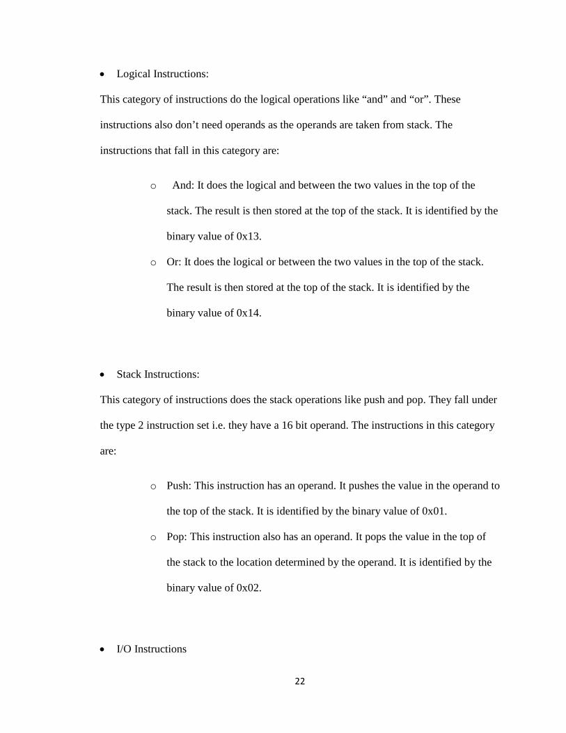
• Logical Instructions:
This category of instructions do the logical operations like “and” and “or”. These
instructions also don’t need operands as the operands are taken from stack. The
instructions that fall in this category are:
o And: It does the logical and between the two values in the top of the
stack. The result is then stored at the top of the stack. It is identified by the
binary value of 0x13.
o Or: It does the logical or between the two values in the top of the stack.
The result is then stored at the top of the stack. It is identified by the
binary value of 0x14.
• Stack Instructions:
This category of instructions does the stack operations like push and pop. They fall under
the type 2 instruction set i.e. they have a 16 bit operand. The instructions in this category
are:
o Push: This instruction has an operand. It pushes the value in the operand to
the top of the stack. It is identified by the binary value of 0x01.
o Pop: This instruction also has an operand. It pops the value in the top of
the stack to the location determined by the operand. It is identified by the
binary value of 0x02.
• I/O Instructions
23
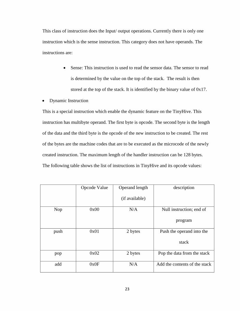
This class of instruction does the Input/ output operations. Currently there is only one
instruction which is the sense instruction. This category does not have operands. The
instructions are:
• Sense: This instruction is used to read the sensor data. The sensor to read
is determined by the value on the top of the stack. The result is then
stored at the top of the stack. It is identified by the binary value of 0x17.
• Dynamic Instruction
This is a special instruction which enable the dynamic feature on the TinyHive. This
instruction has multibyte operand. The first byte is opcode. The second byte is the length
of the data and the third byte is the opcode of the new instruction to be created. The rest
of the bytes are the machine codes that are to be executed as the microcode of the newly
created instruction. The maximum length of the handler instruction can be 128 bytes.
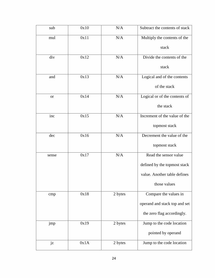
The following table shows the list of instructions in TinyHive and its opcode values:
Opcode Value Operand length
(if available)
description
Nop 0x00 N/A Null instruction; end of
program
push 0x01 2 bytes Push the operand into the
stack
pop 0x02 2 bytes Pop the data from the stack
add 0x0F N/A Add the contents of the stack
24
sub 0x10 N/A Subtract the contents of stack
mul 0x11 N/A Multiply the contents of the
stack
div 0x12 N/A Divide the contents of the
stack
and 0x13 N/A Logical and of the contents
of the stack
or 0x14 N/A Logical or of the contents of
the stack
inc 0x15 N/A Increment of the value of the
topmost stack
dec 0x16 N/A Decrement the value of the
topmost stack
sense 0x17 N/A Read the sensor value
defined by the topmost stack
value. Another table defines
those values
cmp 0x18 2 bytes Compare the values in
operand and stack top and set
the zero flag accordingly.
jmp 0x19 2 bytes Jump to the code location
pointed by operand
jz 0x1A 2 bytes Jump to the code location
25
pointed by operand if Zero
flag is set.
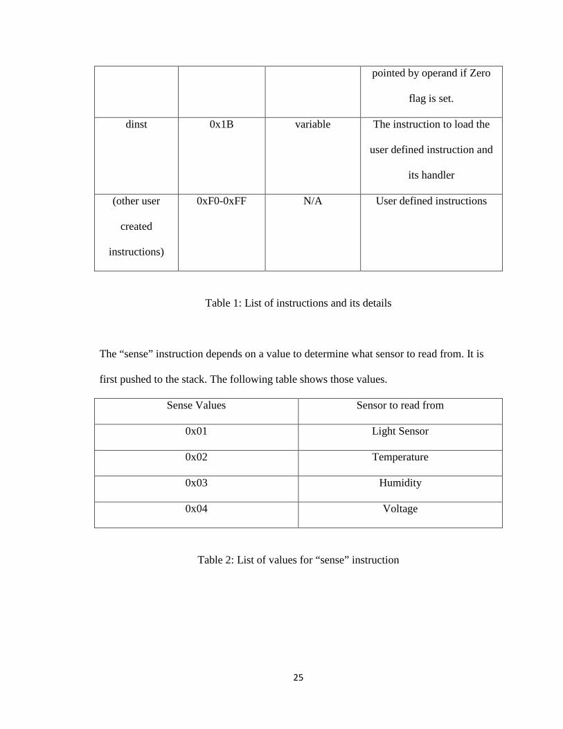
dinst 0x1B variable The instruction to load the
user defined instruction and
its handler
(other user
created
instructions)
0xF0-0xFF N/A User defined instructions
Table 1: List of instructions and its details
The “sense” instruction depends on a value to determine what sensor to read from. It is
first pushed to the stack. The following table shows those values.
Sense Values Sensor to read from
0x01 Light Sensor
0x02 Temperature
0x03 Humidity
0x04 Voltage
Table 2: List of values for “sense” instruction
26
3.5 VIRTUAL CODE INTERPRETER
This is the important component of the TinyHive system. This component does the work
of interpretation and emulation of all the instructions. When the program runs the opcode
is interpreted by it one by one. By seeing the value of the opcode it determines which
emulation function to run. For eg: If it finds the opcode as 0x0F, it determines that the
function to run is the add.simulate(). The detection is done by the switch statement.
The scheduling of the task is non-preemptive. So, the virtual program runs until the task
is over. The scheduling is on a first come first served (FCFS) basis. The VM just waits on
a loop until a virtual task is available to run.
3.6 DYNAMIC INSTRUCTION
The purpose of the research is to make the virtual machine dynamic. Using this
technique, the user can add a custom instruction or procedure and deploy it at runtime.
This addition can then be later used by other virtual programs.
A similar type of feature has been implemented in an Operating system for Sensor
network called SOS [11]. In this operating system a module can be deployed at runtime
and other tasks can use its functions. This has made the SOS operating system very
dynamic. The idea is to use the similar feature for a TinyHive virtual machine.
The idea is to implement an instruction that uploads a procedure or a set of instructions
into the code memory. Now when the virtual program tries to execute the opcode of the
newly added virtual instruction, the code block is executed. The virtual machine stores a
27
set of function pointers (location of added code). So when that virtual code is
encountered, the code block is run. We call that instruction dyninst. For the gateway
program, the program which is responsible for loading of virtual instructions to mote, its
operand is a memory location of the procedure in the binary form. So, the loader program
(gateway) just sends the opcode for dyninst followed by length in bytes of the procedure
followed by the binary code.
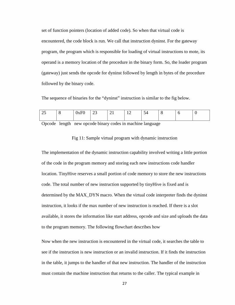
The sequence of binaries for the “dyninst” instruction is similar to the fig below.
25 8 0xF0 23 21 12 54 8 6 0
Opcode length new opcode binary codes in machine language
Fig 11: Sample virtual program with dynamic instruction
The implementation of the dynamic instruction capability involved writing a little portion
of the code in the program memory and storing each new instructions code handler
location. TinyHive reserves a small portion of code memory to store the new instructions
code. The total number of new instruction supported by tinyHive is fixed and is
determined by the MAX_DYN macro. When the virtual code interpreter finds the dyninst
instruction, it looks if the max number of new instruction is reached. If there is a slot
available, it stores the information like start address, opcode and size and uploads the data
to the program memory. The following flowchart describes how
Now when the new instruction is encountered in the virtual code, it searches the table to
see if the instruction is new instruction or an invalid instruction. If it finds the instruction
in the table, it jumps to the handler of that new instruction. The handler of the instruction
must contain the machine instruction that returns to the caller. The typical example in
28
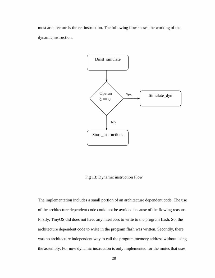
most architecture is the ret instruction. The following flow shows the working of the
dynamic instruction.
Fig 13: Dynamic instruction Flow
The implementation includes a small portion of an architecture dependent code. The use
of the architecture dependent code could not be avoided because of the flowing reasons.
Firstly, TinyOS did does not have any interfaces to write to the program flash. So, the
architecture dependent code to write in the program flash was written. Secondly, there
was no architecture independent way to call the program memory address without using
the assembly. For now dynamic instruction is only implemented for the motes that uses
Dinst_simulate
Operand == 0
Store_instructions
Simulate_dyn Yes
No
29
the AVR cpu. Those motes include micaZ, mica2 and IRIS motes. All the architecture
dependent codes are written in a file called avr.c. There are two functions, one to write in
the flash memory and another to jump to flash memory location where the handler is
stored.
30
CHAPTER IV
FINDINGS
4.1 INTRODUCTION
The purpose of the research is to make the virtual machine dynamic. Using this
technique, the user can add a custom instruction or procedure and deploy it at runtime.
This addition can than be later used by other virtual programs.
A similar type of feature has been implemented in an Operating system for Sensor
network called SOS [11]. In this operating system a module can be deployed at runtime
and other tasks can use its functions. This has made the SOS operating system very
dynamic. The idea is to use the similar feature for a TinyHive virtual machine.
The idea is to implement a instruction that uploads a procedure or a set of instructions
into the code memory. Now when the virtual program tries to execute the opcode of the
newly added virtual instruction, the code block is executed. The virtual machine stores a
set of function pointers (location of added code). So when that virtual code is
encountered, the code block is run. For now I have called that instruction dyninst. For the
gateway program, the program which is responsible for loading of virtual instructions to
mote, its operand is a memory location of the procedure in the binary form. So, the loader
31
program (gateway) just sends the opcode for dyninst followed by length in bytes of the
procedure followed by the binary code.
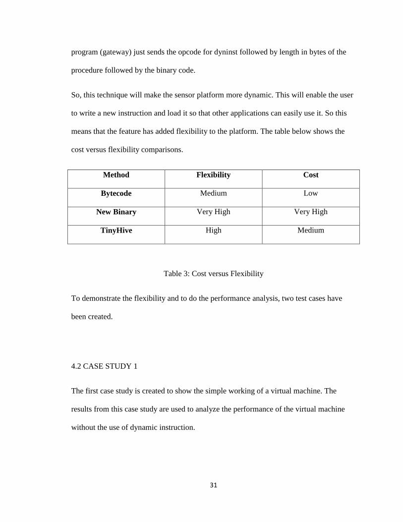
So, this technique will make the sensor platform more dynamic. This will enable the user
to write a new instruction and load it so that other applications can easily use it. So this
means that the feature has added flexibility to the platform. The table below shows the
cost versus flexibility comparisons.
Method Flexibility Cost
Bytecode Medium Low
New Binary Very High Very High
TinyHive High Medium
Table 3: Cost versus Flexibility
To demonstrate the flexibility and to do the performance analysis, two test cases have
been created.
4.2 CASE STUDY 1
The first case study is created to show the simple working of a virtual machine. The
results from this case study are used to analyze the performance of the virtual machine
without the use of dynamic instruction.
32
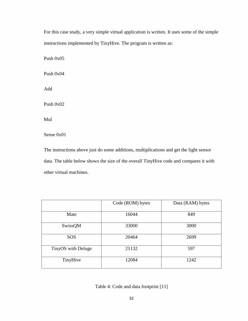
For this case study, a very simple virtual application is written. It uses some of the simple
instructions implemented by TinyHive. The program is written as:
Push 0x05
Push 0x04
Add
Push 0x02
Mul
Sense 0x01
The instructions above just do some additions, multiplications and get the light sensor
data. The table below shows the size of the overall TinyHive code and compares it with
other virtual machines.
Code (ROM) bytes Data (RAM) bytes
Mate 16044 849
SwissQM 33000 3000
SOS 20464 2699
TinyOS with Deluge 21132 597
TinyHive 12084 1242
Table 4: Code and data footprint [11]
33
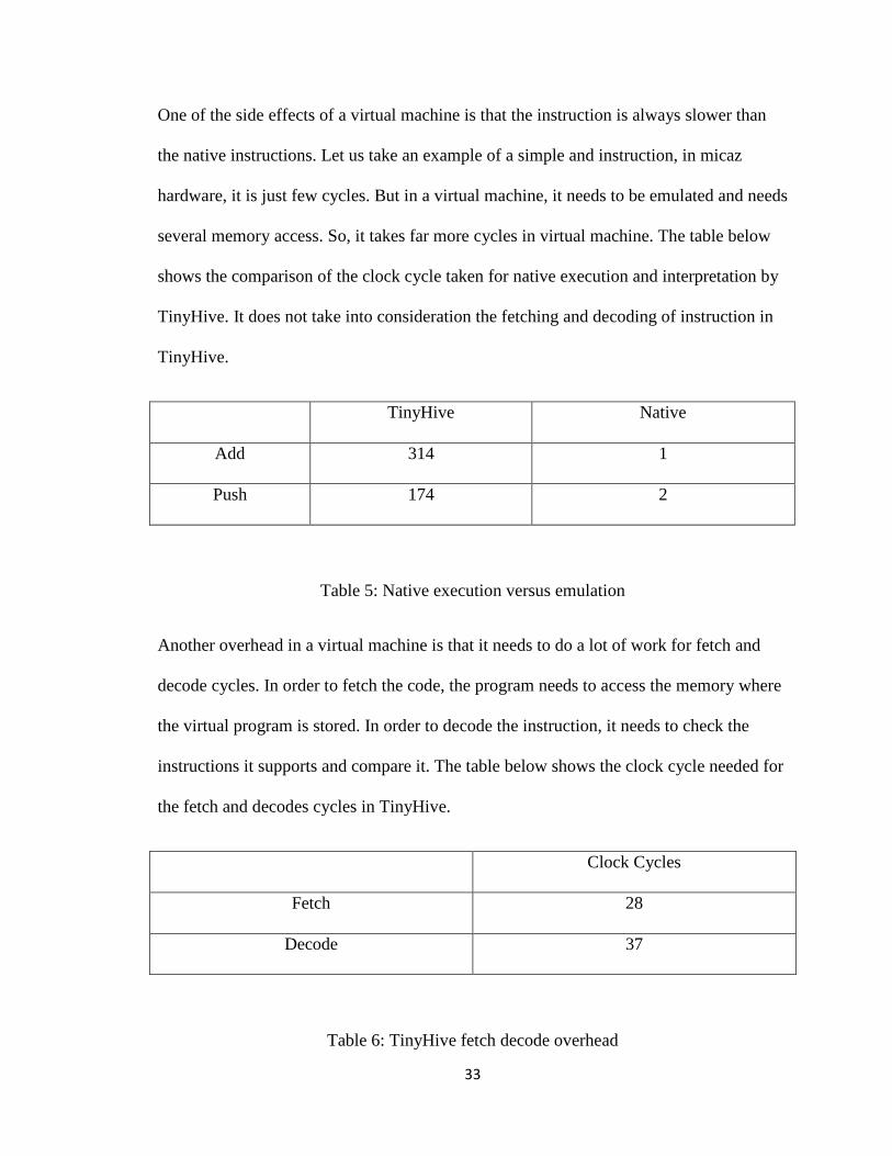
One of the side effects of a virtual machine is that the instruction is always slower than
the native instructions. Let us take an example of a simple and instruction, in micaz
hardware, it is just few cycles. But in a virtual machine, it needs to be emulated and needs
several memory access. So, it takes far more cycles in virtual machine. The table below
shows the comparison of the clock cycle taken for native execution and interpretation by
TinyHive. It does not take into consideration the fetching and decoding of instruction in
TinyHive.
TinyHive Native
Add 314 1
Push 174 2
Table 5: Native execution versus emulation
Another overhead in a virtual machine is that it needs to do a lot of work for fetch and
decode cycles. In order to fetch the code, the program needs to access the memory where
the virtual program is stored. In order to decode the instruction, it needs to check the
instructions it supports and compare it. The table below shows the clock cycle needed for
the fetch and decodes cycles in TinyHive.
Clock Cycles
Fetch 28
Decode 37
Table 6: TinyHive fetch decode overhead
34
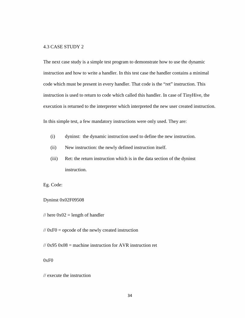
4.3 CASE STUDY 2
The next case study is a simple test program to demonstrate how to use the dynamic
instruction and how to write a handler. In this test case the handler contains a minimal
code which must be present in every handler. That code is the “ret” instruction. This
instruction is used to return to code which called this handler. In case of TinyHive, the
execution is returned to the interpreter which interpreted the new user created instruction.
In this simple test, a few mandatory instructions were only used. They are:
(i) dyninst: the dynamic instruction used to define the new instruction.
(ii) New instruction: the newly defined instruction itself.
(iii) Ret: the return instruction which is in the data section of the dyninst
instruction.
Eg. Code:
Dyninst 0x02F09508
// here 0x02 = length of handler
// 0xF0 = opcode of the newly created instruction
// 0x95 0x08 = machine instruction for AVR instruction ret
0xF0
// execute the instruction
35
Firstly, the dyninst instruction loads the handler in the program memory and later the
newly created instruction is executed.
4.4 CASE STUDY 3
In the next case study, we implement a test program which is used get the soil moisture
sensor data. In this case study we demonstrate how we can use other customized sensors
which are not supported by other virtual machines. This is a real world example where
the TinyHive could be used.
A small program is written to get the sensor data from a soil moisture sensor. In order to
get a soil moisture data, we create a new instruction called “get_moist”. We first upload
the handler to that instruction and then later call that instruction to get the data. The
handler is written in a native code to the AVR processor. The virtual application is
written using a TinyHive instruction set.
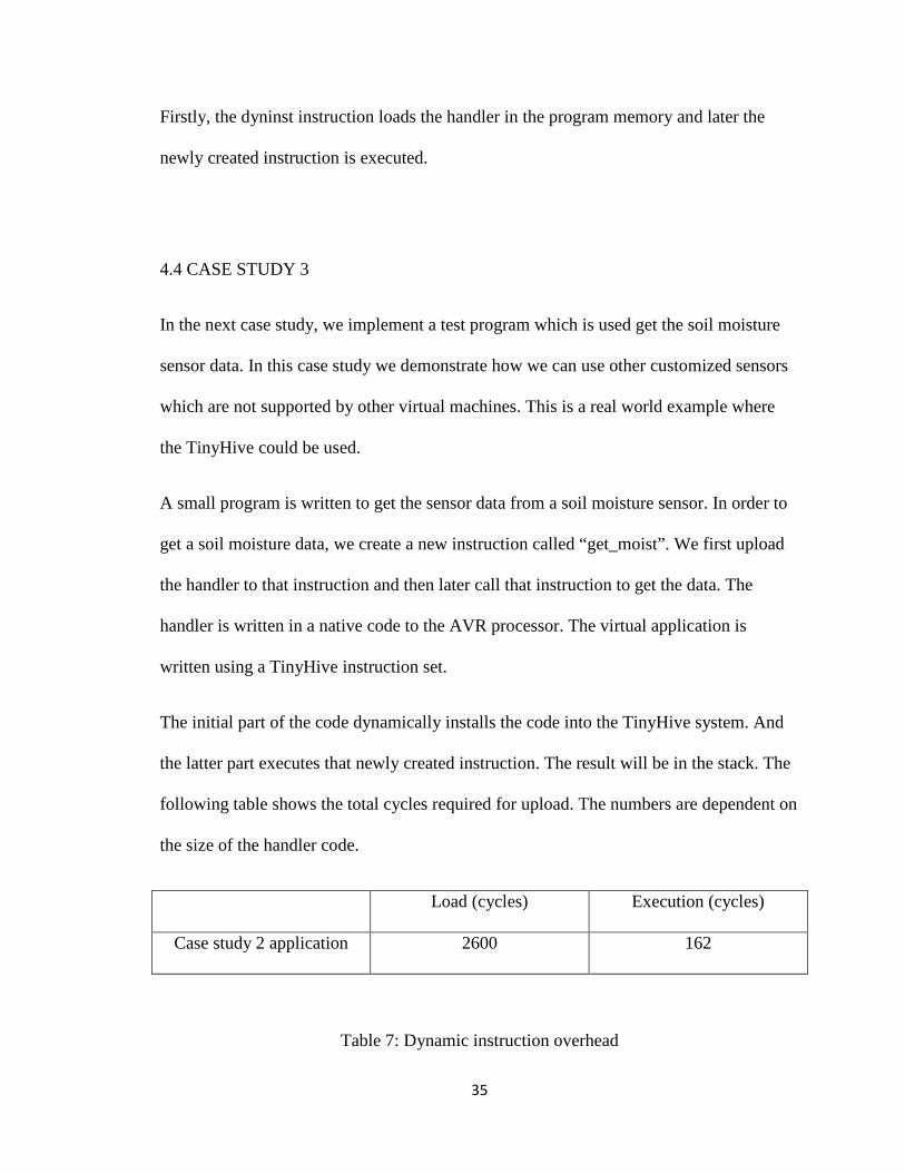
The initial part of the code dynamically installs the code into the TinyHive system. And
the latter part executes that newly created instruction. The result will be in the stack. The
following table shows the total cycles required for upload. The numbers are dependent on
the size of the handler code.
Load (cycles) Execution (cycles)
Case study 2 application 2600 162
Table 7: Dynamic instruction overhead
36
4.4 ENERGY USAGE ANALYSIS
One of the other most important benefits of virtual machine is the energy usage while
reprogramming. On a system without virtual machine there are only two ways to
reprogram the mot. One is to physically access the mote which might not be feasible.
Another option is to use middleware application like Deluge. The Deluge middleware
application receives the whole binary through radio and writes the whole program in the
flash. Writing in a flash memory is expensive as it used a lot of power.
On a system with a virtual machine it does not need to write in program memory but it
not flexible. In TinyHIve, a new instructed can be added whose handler in written in
program memory. Since the handler is very small compared to the whole binary, it
consumes less power than deluge. In ATMega128, we can only write one page at a time
which is 256 bytes. The energy required to write 1 page is 0.31 mJ [11]. In this analysis,
the power used to transmit the code and execute the code is not taken into consideration.
The power only required to write the program memory is considered because the design
of TinyHive improves power usage while handler is written in program memory.
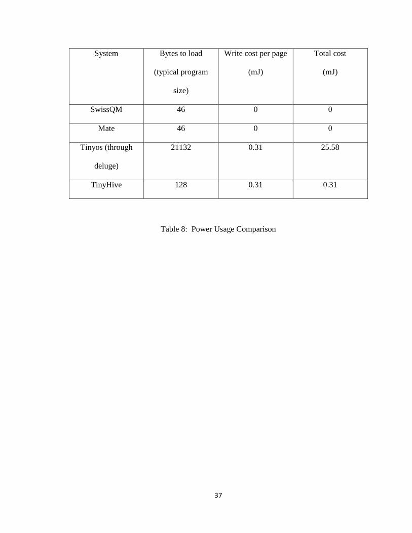
The following table shows the energy usage while writing to the program memory.
37
System Bytes to load
(typical program
size)
Write cost per page
(mJ)
Total cost
(mJ)
SwissQM 46 0 0
Mate 46 0 0
Tinyos (through
deluge)
21132 0.31 25.58
TinyHive 128 0.31 0.31
Table 8: Power Usage Comparison
38
CHAPTER V
CONCLUSION
Virtual machine for sensor network is becoming a very popular topic these days. One of
the main benefits of a virtual machine is the flexibility it provides. Though, this flexibility
comes with a tradeoff of execution cost. But the flexibility it provides is far more than the
execution cost.
The developers started thinking about making sensor network application more flexible
by first designing systems like deluge. Deluge made the system flexible but it had major
power cost involved. Later, the virtual machines were developed for sensor networks.
The virtual machines like Mate and SwissQM had the ability to send a new program
through radio. But those programs’s functionality was limited by the instruction set they
provided.
So, this research has come up with a technique which enables the expansion of
functionality of a virtual machine. This is achieved by adding the ability to add a user
defined instruction. The user can write the handler according to the needs of his
application. The handler is written in a native code executed by the underlying micro-
controller. This makes the virtual machine very dynamic. The working of this
functionality is shown by two use cases described in results section.
39
The first test case shows how one can write an application using TinyHive instructions.
The second test case shows how one can define his own instruction which does a specific
job which is not possible without that feature. As an example soil moisture sensor is used
for this purpose. The results show that though the virtual programs take more CPU cycles
than native instructions, they are much more flexible. From the results we can see that,
TinyHive is more flexible than regular virtual machines like mate and SwissQM. It can
also be seen from the results section that it consumes less power than having to write the
whole program in flash.
So we can conclude that TinyHive is very flexible and dynamic. And it consumes less
power even though it needs some program memory writes. There are also few problems
with this system. One problem is that program memory can only be written 10,000 times.
So this loading of new instruction has to be rare. Secondly, TinyHive is in the infant age
of its development. So there is no easy way to write a handler function than to use a
native instruction. Thus, TinyHive can help in creating more dynamic applications for
sensor networks.
The TinyHive in currently in the infant stage and needs a lot of work. The following are
the future work that can be either improved or implemented in TinyHive.
• A new GUI based gateway program can be implemented. It could load the
TinyHive virtual application. In addition, it could also enable the user to write
virtual applications in simple English.
• Another efficient way could be developed to write the handler of the new user
created instruction.
40
• We can implement the radio code where there virtual applications can be
transmitted through the radio.
• The size of the program can currently be as big as the maximum size of the
packet. This can be extended by implementing the feature where 1 application can
be sent using multiple packets.
• The instructions related to the use of radio and serial can be added. we can have
send and receive instructions for both radio and serial.
These are some of the things that can be implemented in TinyHive as future work.
41
REFERENCES
[1] TinyOS programming guide, http://www.tinyos.net.
[2] René Müller, Gustavo Alonso, Donald Kossmann: SwissQM: Next Generation Data
Processing in Sensor Networks In Proceedings of the 3rd Biennial Conference on
Innovative Data Systems Research, Asilomar, CA, USA, January 7-10th 2007.
[3] René Müller, Gustavo Alonso: Efficient Sharing of Sensor Networks In Proceedings
of the 3rd IEEE International Conference on Mobile Ad-hoc and Sensor Systems 2006,
Vancouver, Canada, October 9-12th 2006.
[4] René Müller, Gustavo Alonso: Shared Queries in Sensor Networks for Multi-User
Support Technical Report 508, Department of Computer Science, ETH Zurich, February
2006
[6] J. W. Hui, and D. Culler, “The dynamic behavior of a data dissemination protocol for
network programming at scale”, In SenSys , pp: 81–94, 2004.
[7] S. R. Madden, M. J. Franklin, J. M. Hellerstein, and W. Hong. TinyDB: an
acquisitional query processing system for sensor networks. ACM Trans. Database Syst.,
30(1):122–173, 2005.
42
[8] Philip Levis, and David Culler, “Mate: A tiny Virtual machine for sensor networks”,
on Proceedings of the 10th international conference, October 05, 2002
[9] Samuel R. Madden, Wei Hong, Michel J. Franklin and Joseph M. Hellerstein,
"TinyDB: An Acquisitional Query Processing System for Sensor Networks1", ACM
transactions on Database systems, 2005
[10] Ren´e M¨ uller, Gustavo Alonso, and Donald Kossmann, "A Virtual Machine for
Sensor Networks", In Proceedings of EuroSys 2007, Lisbon, Portugal, March 21-23th
2007
[11] Chih-Chieh Han, Ram Kumar Rengaswamy, Roy Shea, Eddie Kohler and Mani
Srivastava, "SOS: A dynamic operating system for sensor networks", Proceedings of the
Third International Conference on Mobile Systems, Applications, And Services
(Mobisys), 2005
[12] Adam Dunkels, Björn Grönvall, and Thiemo, "Contiki - a Lightweight and Flexible
Operating System for Tiny Networked Sensors", Thiemo Voigt. IEEE Emnets 2004
[13] Gerald J. Popek, and Robert P. Goldberg, "Formal Requirements for Virtualizable
Third Generation Architectures", Communications of the ACM 17 (7): pp 412 –421,
1974
[14] VMware virtual machine. http://www.vmware.com
[15] David L. Black, David B. Golub, Daniel P. Julin, Richard F. Rashid, Richard P.
Draves, Randall W. Dean, Alessandro Forin, Joseph Barrera, Hideyuki Tokuda, Gerald
43
Malan, David Bohman, "Microkernel Operating system Architecture and Mach",
USENIX Workshop on Micro-Kernels and Other Kernel, 1992
[16] B. Folliot, I. Piumarta, and F. Riccardi. A dynamically configurable, multi-language
execution platform. In Proc. of 8th ACM SIGOPS European Workshop, 1998.
[17] MicaZ mote http://www.xbow.com
[18] Stefan Beyer, Robert Taylor, Ken Mayes, "Operating System Support for Dynamic
Code Loading in Sensor Networks,", pp.311-315, Fourth IEEE International Conference
on Pervasive Computing and Communications Workshops (PERCOMW'06), 2006.
[19] David Gay, Philip Levis, Robert von Behren, Matt Welsh, Eric Brewer, and David
Culler, "The nesC language: A holistic approach to networked embedded systems",
Conference on Programming Language Design and Implementation Proceedings of the
ACM SIGPLAN 2003 conference on Programming language design and implementation,
San Diego, California, USA, 2008.
[20] S. Beyer, K. Mayes, and B. Warboys. “Dynamic configuration of embedded
operating systems.” In WIP Proceedings of the 24th IEEE Real-Time Systems
Symposium, pages 23–26, December 2003.
[21] P. Levis, N. Lee, M. Welsh, and D. Culler. "Tossim: accurate and scalable
simulation of entire tinyos applications." In SenSys 2003, pages 126–137, 2003.
[22] Dunkels, Gronvall, and Voigt, "Contiki - a lightweight and flexible operating system
for tiny networked sensors.", In Proceedings of the First IEEE Workshop on Embedded
Networked Sensors, 2004.
44
[23] Atmel ATmega128 datasheet, www.atmel.com/atmel/acrobat/doc2467.pdf
[24] Rahul Balani, Chih-Chieh Han, Ram Kumar Rengaswamy, Ilias Tsigkogiannis,
Mani Srivastava, "Multilevel Software Reconfiguration for Sensor Networks" in
Proceedings of the 6th ACM & IEEE International conference on Embedded software,
2006.
[25] MicaZ motes (UC Berkeley/Crossbow). http://www.xbow.com/.
[26] Niels Reijers , Koen Langendoen, Efficient code distribution in wireless sensor
networks, Proceedings of the 2nd ACM international conference on Wireless sensor
networks and applications, September 19-19, 2003, San Diego, CA, USA.
[27] Atmel AVR simulator, http://avr.sourceforge.net.
[28] P. Stanley-Marbell , L. Iftode, Scylla: a smart virtual machine for mobile embedded
systems, Proceedings of the Third IEEE Workshop on Mobile Computing Systems and
Applications (WMCSA'00), p.41, December 07-08, 2000.
[29] Tim Lindholm , Frank Yellin, Java Virtual Machine Specification, Addison-Wesley
Longman Publishing Co., Inc., Boston, MA, 1999
[30] Lloyd I. Dickman, Small virtual machines: A survey, Proceedings of the workshop
on virtual computer systems, p.191-202, March 26-27, 1973, Cambridge, Massachusetts,
United States.
[31] Lars Ræder Clausen , Ulrik Pagh Schultz , Charles Consel , Gilles Muller, Java
bytecode compression for low-end embedded systems, ACM Transactions on
Programming Languages and Systems (TOPLAS), v.22 n.3, p.471-489, May 2000
45
[32] R. P. Goldberg, Architecture of virtual machines, Proceedings of the workshop on
virtual computer systems, p.74-112, March 26-27, 1973, Cambridge, Massachusetts,
United States.
46
APPPENDIX A: MANUAL
The Source code of the TinyHive is stored in a SVN server. We have created a repository
for TinyHive project in SVN. The path to the project is
https://www.cs.okstate.edu/svn/s3lab/tinyhive/. In order to check out the code, the user
should use the command:
svn checkout https://www.cs.okstate.edu/svn/s3lab/tinyhive --username <your cs server
username>
After checking out you can make the changes to the files. If you wish to commit the
changes do svn commit -m "put your comment on what changes you made in short".
Please make sure you fix all compile errors before committing.
Currently, the access is for Oklahoma State University Computer science students only.
In order to compile the code, the architecture dependent code needs to be compiled
separately. It is written in C. It can be compiled as follows for MicaZ platforms (or any
other platform that used AVR).
avr-gcc -c –mmcu=atmega128 avr.c
Then the remaining code can be compiled as:
Make micaz
47
Then it can be written to the mote as:
Make micaz reinstall mib520, <serial port>
where, serial port is the serial port name. In Linux, it is usually /dev/TTYUSB0. Mib520 is the board we used.
The files in the TinyOS code directory are:
S3vm.h
Avr.c
Arith.nc
Control.nc
Dyninst.nc
Makefile
S3vm.nc
S3vmapp.nc
S3vmc.nc
S3vmisa.nc
Sensor.nc
Serialcomm.nc
Stack.nc
Stackc.nc
Stackops.nc
48
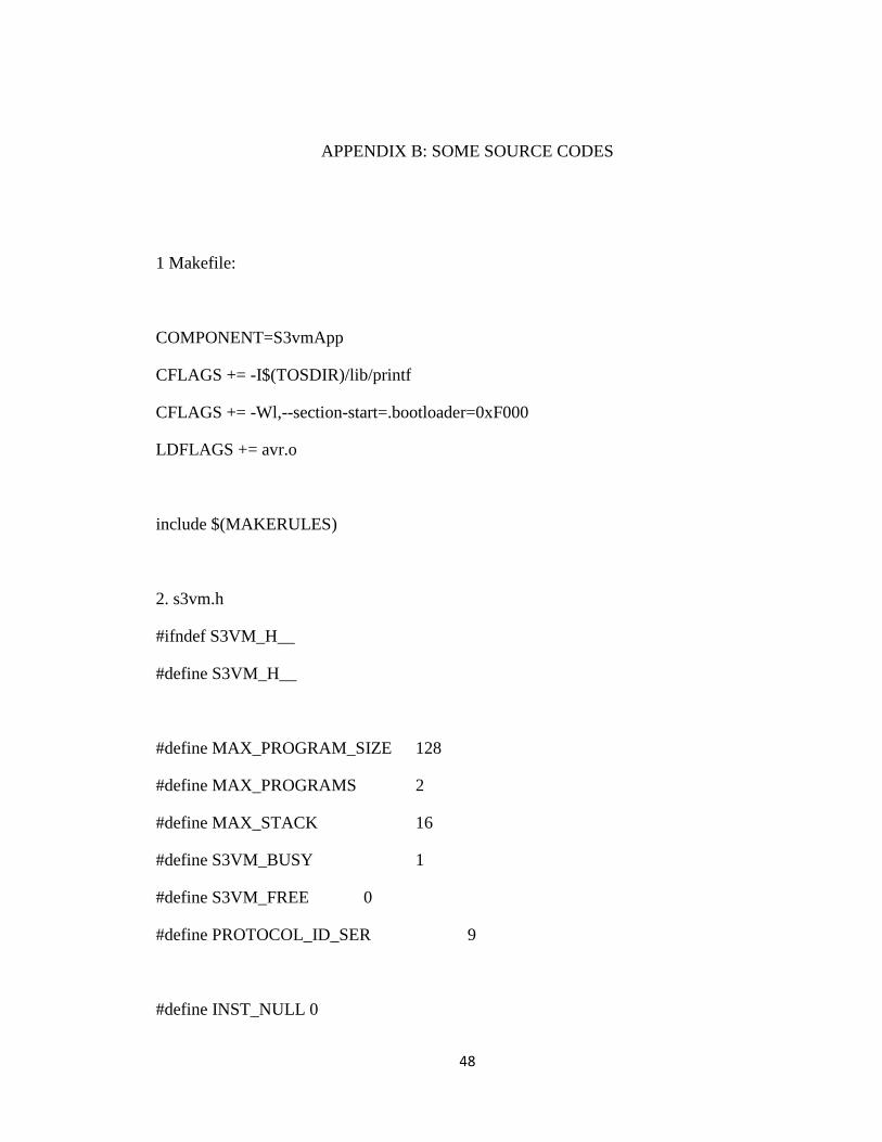
APPENDIX B: SOME SOURCE CODES
1 Makefile:
COMPONENT=S3vmApp
CFLAGS += -I$(TOSDIR)/lib/printf
CFLAGS += -Wl,--section-start=.bootloader=0xF000
LDFLAGS += avr.o
include $(MAKERULES)
2. s3vm.h
#ifndef S3VM_H__
#define S3VM_H__
#define MAX_PROGRAM_SIZE 128
#define MAX_PROGRAMS 2
#define MAX_STACK 16
#define S3VM_BUSY 1
#define S3VM_FREE 0
#define PROTOCOL_ID_SER 9
#define INST_NULL 0
49
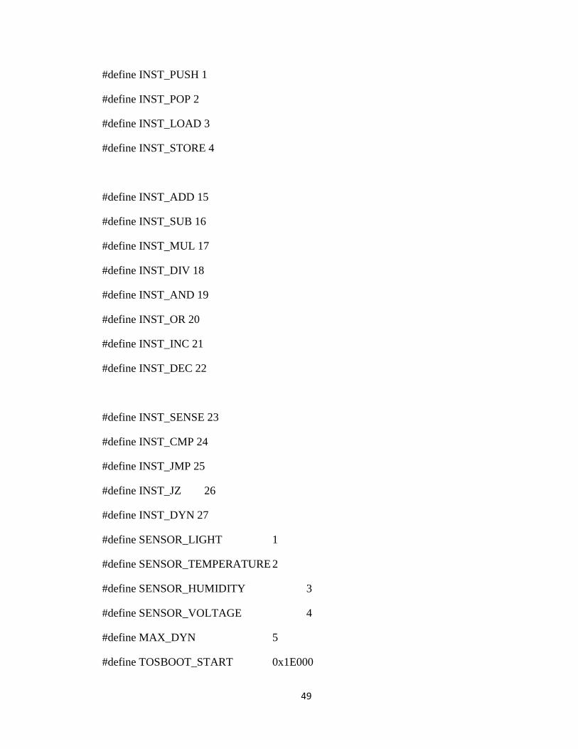
#define INST_PUSH 1
#define INST_POP 2
#define INST_LOAD 3
#define INST_STORE 4
#define INST_ADD 15
#define INST_SUB 16
#define INST_MUL 17
#define INST_DIV 18
#define INST_AND 19
#define INST_OR 20
#define INST_INC 21
#define INST_DEC 22
#define INST_SENSE 23
#define INST_CMP 24
#define INST_JMP 25
#define INST_JZ 26
#define INST_DYN 27
#define SENSOR_LIGHT 1
#define SENSOR_TEMPERATURE 2
#define SENSOR_HUMIDITY 3
#define SENSOR_VOLTAGE 4
#define MAX_DYN 5
#define TOSBOOT_START 0x1E000
50
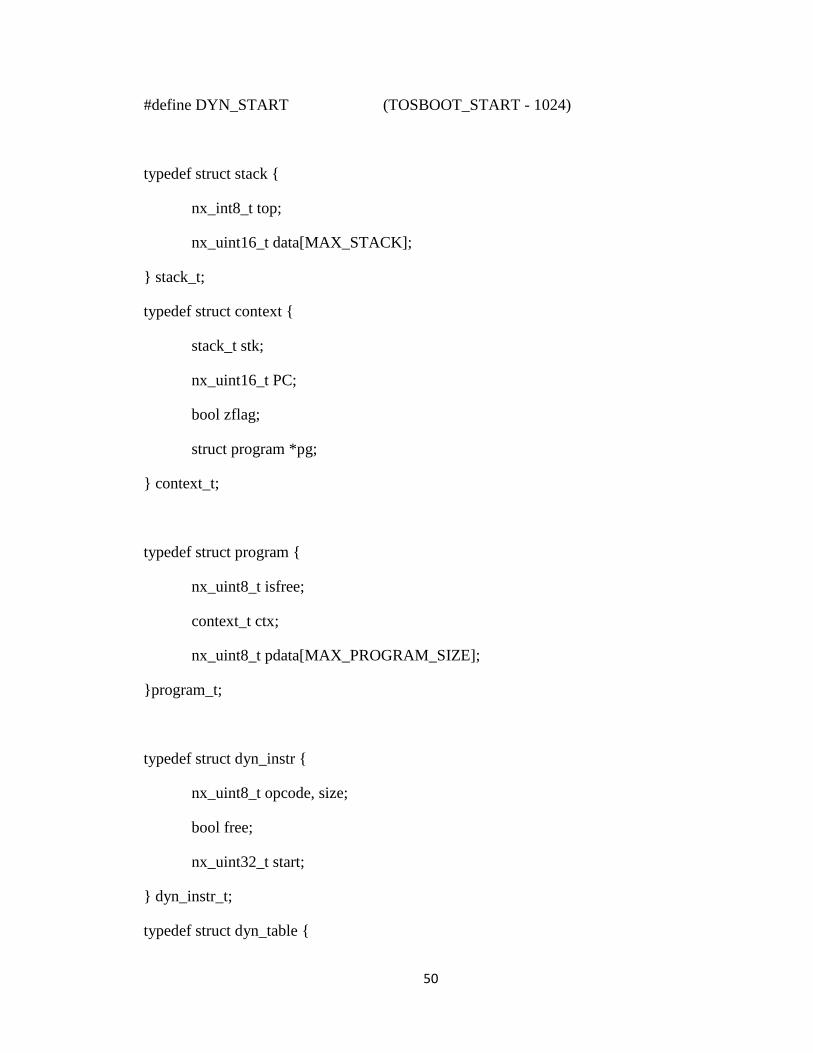
#define DYN_START (TOSBOOT_START - 1024)
typedef struct stack {
nx_int8_t top;
nx_uint16_t data[MAX_STACK];
} stack_t;
typedef struct context {
stack_t stk;
nx_uint16_t PC;
bool zflag;
struct program *pg;
} context_t;
typedef struct program {
nx_uint8_t isfree;
context_t ctx;
nx_uint8_t pdata[MAX_PROGRAM_SIZE];
}program_t;
typedef struct dyn_instr {
nx_uint8_t opcode, size;
bool free;
nx_uint32_t start;
} dyn_instr_t;
typedef struct dyn_table {
51
struct dyn_instr dyn_instr[MAX_DYN];
} dyn_table_t;
extern int copy_to_flash(nx_uint32_t addr, nx_uint8_t *data, nx_uint8_t len);
#endif // S3VM_H__
3. avr.c
int BOOTLOADER_SECTION copy_to_flash(uint32_t addr, uint8_t *data, uint8_t len)
{
uint16_t* instr = (uint16_t*)data;
uint32_t i;
uint8_t pgmdata, sreg;
if ( addr + len > 0x1f000 )
return 0;
sreg = SREG;
eeprom_busy_wait ();
boot_page_erase( addr );
while( boot_rww_busy() )
boot_rww_enable();
52
for (i=0; i<SPM_PAGESIZE; i+=2)
{
boot_page_fill(addr + i, *instr++);
}
boot_page_write (addr); // Store buffer in flash page.
while ( boot_rww_busy() )
boot_rww_enable();
SREG = sreg;
return 1;
}
4. s3vmapp.nc
#include "printf.h"
#include "s3vm.h"
configuration S3vmApp {
provides interface S3vmC;
}
implementation {
53
components MainC, s3vm, LedsC, StackC;
components new TimerMilliC() as Timer;
components new TimerMilliC() as Timer0;
components StackOps, arith, dyninst;
components SerialComm;
components SerialActiveMessageC as AM;
S3vmC = s3vm.S3vmC;
s3vm.Boot -> MainC;
s3vm.Stack -> StackC.Stack;
// Instructions
s3vm.S3vmISA[INST_PUSH] -> StackOps.push;
s3vm.S3vmISA[INST_POP] -> StackOps.pop;
s3vm.S3vmISA[INST_ADD] -> arith.add;
s3vm.S3vmISA[INST_SUB] -> arith.sub;
s3vm.S3vmISA[INST_MUL] -> arith.mul;
s3vm.S3vmISA[INST_DIV] -> arith.div;
s3vm.S3vmISA[INST_INC] -> arith.inc;
s3vm.S3vmISA[INST_DEC] -> arith.dec;
s3vm.S3vmISA[INST_AND] -> arith.and;
s3vm.S3vmISA[INST_OR] -> arith.or;
s3vm.S3vmISA[INST_DYN] -> dyninst.dinst;
54
dyninst.Leds -> LedsC;
StackOps.Stack -> StackC.Stack;
arith.Stack -> StackC.Stack;
SerialComm.Control -> AM;
SerialComm.Receive -> AM.Receive[PROTOCOL_ID_SER];
SerialComm.Timer -> Timer0;
SerialComm.Packet -> AM;
SerialComm.S3vmC -> s3vm.S3vmC;
}
VITA
MANISH REGMI
Candidate for the Degree of
Master of Science Thesis: TINYHIVE: DYNAMIC VIRTUAL MACHINE FOR SENSOR NETWORKS Major Field: Computer Science Biographical:
Education: Completed the requirements for the Master of Science in Computer Science at Oklahoma State University, Stillwater, Oklahoma in December, 2009.
ADVISER’S APPROVAL: Dr. Xiaolin Li
Name: Manish Regmi Date of Degree: December, 2009 Institution: Oklahoma State University Location: Stillwater, Oklahoma Title of Study: TINYHIVE: DYNAMIC VIRTUAL MACHINE FOR SENSOR
NETWORKS Pages in Study: 54 Candidate for the Degree of Master of Science
Major Field: Computer Science Scope and Method of Study: The scope of this study is to design and analyze a dynamic virtual machine. Virtual machines are becoming a popular area of research. One of the most important benefits from virtual machine is flexibility for redeployment. Though, this flexibility comes at a cost of slightly slow code. So far researchers have tried to create a static virtual machine. But they all have a common problem, dynamicity. This project creates a dynamic virtual machine called TinyHive. It enables the user to define his instruction and its handler. The user can write the handler according to the needs of his application. The handler is written in a native code executed by the underlying micro-controller. This makes the virtual machine very dynamic. Findings and Conclusions: Through the use of test cases, we show that TinyHive can enable a virtual application to achieve which was not possible in traditional virtual machines. The user can define his instruction and its handler extending the scope of a virtual machine application. The study also shows that it is much cheaper power wise to write a handler in program memory than other systems like deluge. Thus TinyHive virtual machine can be used to create an application which is more dynamic and flexible than other virtual applications.