times microwave systems tech · pdf file(800) tms-coax • 217 times microwave systems...
TRANSCRIPT
(800) TMS-COAX • www.timesmicrowave.com216
TIMES MICROWAVE SYSTEMS
Tech
Not
es
Choosing the best coaxial cable for a new application requires an understanding of the application and of the range of cables to choose from. The best choice can only be arrived at by a careful evaluation of the performance and cost trade-offs. Our in-depth expertise in all aspects of coaxial cable technology can help you to arrive at the best choice for your application. Times Microwave Systems offers the broadest range of coaxial cables of any manufacturer. We also have the expertise to design and produce custom cables if there is no design available for your application. In choosing the best coaxial cable for an application, the cable characteristics listed below should be considered. The following sections provide detailed discussions of each characteristic.
A: Characteristic Impedance B: VSWR & Impedance Uniformity C: Attenuation · Attenuation Uniformity · Attenuation Stability D: Power Rating E: Operating Voltage F: Shielding G: Capacitance H: Velocity of Propagation I: Electrical Length Stability J: Cut-Off Frequency K: Pulse Response L: Self-Generated Cable Noise M: Operating Temperature Range N: Flexibility O: Environmental Resistance P: Cable Strength Q: Qualification & U L Approval
Table 1 provides various formulae describing cable characteristics.
A. CHARACTERISTIC IMPEDANCE The characteristic impedance of a coaxial cable is determined by the ratio of the diameter of the outer conductor to the inner conductor and the dielectric
constant of the insulating material between the conductors. Because the RF energy in the cable travels on the surface of the conductors, the important diameters are the outside diameter of the center conductor and the inside diameter of the outer conductor. Impedance is selected to match the system requirements. The most common coaxial cables impedances are 50, 75, and 95 ohm. Other impedances from 35 to 185 ohms are sometimes used. Fifty ohm cables are used in microwave and wireless communications applications. Seventy-five ohm cables are typically used in cable television applications and video applications. Ninety-five ohm cables are typically used for data transmission applications. For best system performance, the cable must be selected to match the impedance of the other components in the system. Of the most commonly used coaxial cables, 75 ohms impedance provides the lowest attenuation and 35 ohms impedance provides the best power handling. For practical cables with non-ideal dielectrics and conductors, these differences are small. The availability of required
A guide to the selection of RF coaxial cableFig. 1
VSWR vs. Frequency

(800) TMS-COAX • www.timesmicrowave.com 217
TIMES MICROWAVE SYSTEMS
Tech
Not
es
components and cables with the appropriate characteristic impedance is usually the prime factor in selecting a given system impedance.
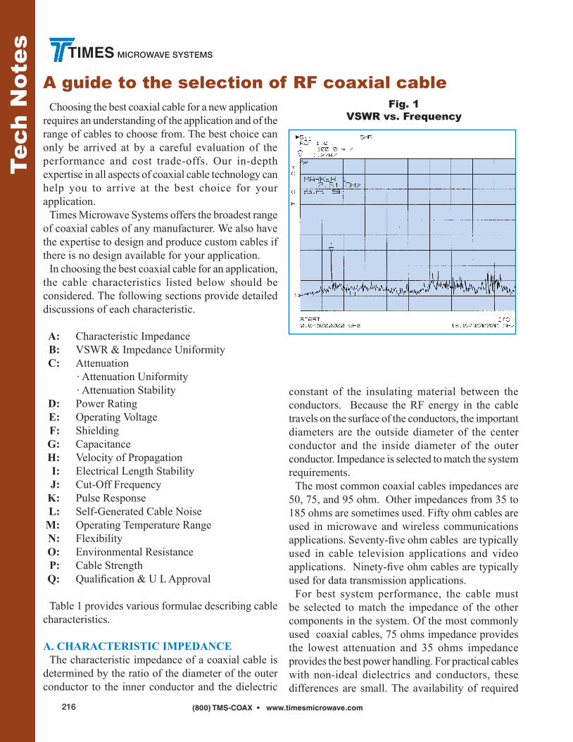
B. SIGNAL REFLECTION: VSWR, RETURN LOSS, REFLECTION FACTOR & IMPEDANCE UNIFORMITY There are three things that happen to RF energy input into a coaxial cable assembly: 1. It is transmitted to the other end of the cable, as is usually desired.2. It is lost along the length of the cable either by being transformed into heat or by leaking out of the cable.3. It is reflected back towards the input end of the cable. Reflections back towards the input end of the cable are caused by variations in impedance along the length of the cable assembly. This includes differences in impedance between the cable and the devices to which it is attached. Typically the connectors and the interface between the connectors and the cable will be major contributors to the reflection. The cable itself can also contribute to the reflections. One source of cable reflections is periodic variations in impedance which result from the manufacturing process and add up at a specific frequency. When viewed in a sweep over a range of frequencies this will show up as a spike. An example of a spike is shown in Figure 1. The magnitude of a reflection can be expressed in several ways. Perhaps the most familiar is VSWR or Voltage Standing Wave Ratio. A value of 1.0:1 or just 1.0 indicates no reflected power or a perfect cable. Alternatively, the reflection can be expressed as return loss—the ratio of the reflected power to the input power usually expressed in decibels. Table 1 gives the formulas to convert between VSWR, return loss and reflection coefficient. A tabulation of the equivalent values of all three measures is also provided in Table 2. The lack of reflected power (or low VSWR) is often used as a figure of merit for coaxial components, including cables, connectors and cable assemblies. It is indicative of how well the uniformity of the cable is
Table 2VSWR Conversions
VSWR Return Reflection Mismatch Match (:1) Loss (dB) Coefficient Loss (dB) Efficiency (%)
1.011 45 0.006 0.000 100.00
1.020 40 0.010 0.000 99.99
1.036 35 0.018 0.001 99.97
1.065 30 0.032 0.004 99.90
1.074 29 0.035 0.005 99.87
1.08 28 0.400 0.007 99.84
1.09 27 0.045 0.009 99.80
1.11 26 0.050 0.011 99.75
1.12 25 0.056 0.014 99.68
1.13 24 0.063 0.017 99.60
1.15 23 0.071 0.022 99.50
1.17 22 0.079 0.027 99.37
1.20 21 0.089 0.035 99.21
1.22 20 0.100 0.044 99.00
1.25 19 0.112 0.055 98.74
1.29 18 0.126 0.069 98.42
1.33 17 0.141 0.088 98.00
1.38 16 0.158 0.110 97.49
1.43 15 0.178 0.140 96.84
1.50 14 0.200 0.176 96.02
1.58 13 0.224 0.223 94.99
1.67 12 0.251 0.283 93.69
1.78 11 0.282 0.359 92.06
1.92 10 0.316 0.458 90.00
2.10 9 0.355 0.584 87.41
2.32 8 0.398 0.749 84.15
2.61 7 0.447 0.967 80.05
3.01 6 0.501 1.256 74.88
3.57 5 0.562 1.651 68.38
4.42 4 0.631 2.205 60.19
5.85 3 0.708 3.021 49.88
Match efficiency - e.g. 100 Watts Forward Power at 1.33:1 VSWR yields 98 Watts Output (i.e. 2 Watts Reflected)

(800) TMS-COAX • www.timesmicrowave.com218
TIMES MICROWAVE SYSTEMS
Tech
Not
es
maintained along its length, whether the connectors are properly designed and attached and how well the transitions between line sizes are compensated for in the connectors. It is generally a function of frequency, with reflections generally getting higher as the frequency increases. In many applications, low reflected power is critical for proper system performance. In these cases, it is essential that this be considered in the selection of the cable and connectors. In addition, care must be taken to properly attach the connectors to the cable in order to achieve the proper results. Purchase of completed, factory assembled and tested cable assemblies should be considered for VSWR critical applications. Note that actual input impedance at a particular frequency may be quite different from the characteristic impedance of the cable due to reflections in the line. The Voltage Standing Wave Ratio (or VSWR) of a particular length of cable is an indicator of the difference between the actual input impedance of the cable and its average characteristic impedance.
The impedance of long lengths of cable will exhibit very little change over their operating temperature ranges - less than 2%. It is possible to fabricate cables having a characteristic impedance that varies through the length of the cable for matching purposes. Thus a coaxial cable can be used as a broadband impedance transformer to match differing source and load impedances. The transforming action is related to cable length and the minimum operating frequency, and the cable must be designed for the specific application.
C. ATTENUATIONAttenuation is the loss of signal along the length of a cable. As the RF signal passes through the cable, a portion of the signal is converted to heat and a portion of the signal leaks out of the cable through the outer conductor. This loss of signal is usually expressed in decibels per unit of length at a specific frequency, since attenuation increases with frequency. For most applications, the objective is to minimize the losses in the cable runs or to stay within a loss budget. Minimum loss corresponds to an attenuation of 0 dB or a ratio of 1 to 1 between input and output power. Because cable losses decrease with increasing
A guide to the selection of RF coaxial cableFig. 3
Attenuation vs. Frequency
Fig. 2 Attenuation Temperature
Correction Factor

(800) TMS-COAX • www.timesmicrowave.com 219
TIMES MICROWAVE SYSTEMS
Tech
Not
es
cable diameter for the same type of construction, minimizing cable loss means maximizing cable size. Attenuation is determined by the conductive and dielectric losses of the cable. Larger cables have lower conductor losses, reducing attenuation. Dielectric loss is independent of size. Dielectric losses increase linearly with frequency, while conductor losses increase with the square root of frequency. Therefore, dielectric losses become a larger proportion of the total cable loss as frequency increases. Attenuation must be modified by a correction factor for the ambient temperature (see Figure 2). Elevated temperature increases cable attenuation by increasing the resistance of the conductors and by increasing the power factor of the dielectric (see Figure 6 for correction factors). To select a cable construction for a particular application, determine the desired attenuation at the highest frequency from system requirements. Determine the corrected attenuation by dividing the desired attenuation by the temperature correction
factor. Choose the smallest cable meeting the corrected attenuation value from the tables. For cables with low attenuation for their size,see the LMR, StripFlex, SFT, and CLL families of cables.
Attenuation Uniformity The attenuation of any cable may not change uniformly as the frequency changes. Random and periodic impedance variations give rise to random and periodic attenuation responses. Narrow-band attenuation “spikes” such as that shown in Figure 3 can occur. If required, cables can be procured in various lengths where a maximum attenuation variation from nominal is specified over a customer defined frequency range.
Attenuation Stability The attenuation of braided cables can increase with time and flexure. The change with time can be caused by corrosion of the braided shield, by contamination of the primary insulation due to jacket plasticizers, and by moisture penetration through the jacket. These
Fig. 4 Attenuation vs. Flexure
Fig. 5Attenuation Stability
(800) TMS-COAX • www.timesmicrowave.com220
TIMES MICROWAVE SYSTEMS
Tech
Not
es
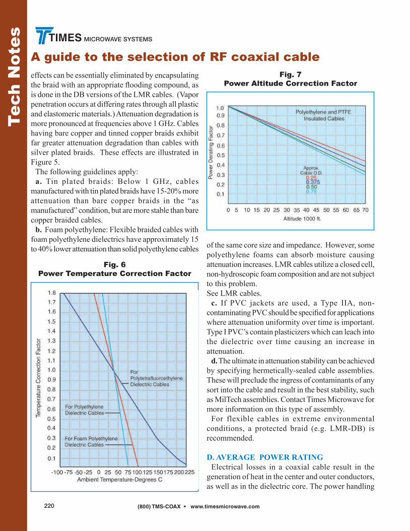
A guide to the selection of RF coaxial cableeffects can be essentially eliminated by encapsulating the braid with an appropriate flooding compound, as is done in the DB versions of the LMR cables. (Vapor penetration occurs at differing rates through all plastic and elastomeric materials.) Attenuation degradation is more pronounced at frequencies above 1 GHz. Cables having bare copper and tinned copper braids exhibit far greater attenuation degradation than cables with silver plated braids. These effects are illustrated in Figure 5. The following guidelines apply: a. Tin plated braids: Below 1 GHz, cables manufactured with tin plated braids have 15-20% more attenuation than bare copper braids in the “as manufactured” condition, but are more stable than bare copper braided cables. b. Foam polyethylene: Flexible braided cables with foam polyethylene dielectrics have approximately 15 to 40% lower attenuation than solid polyethylene cables of the same core size and impedance. However, some
polyethylene foams can absorb moisture causing attenuation increases. LMR cables utilize a closed cell, non-hydroscopic foam composition and are not subject to this problem. See LMR cables. c. If PVC jackets are used, a Type IIA, non-contaminating PVC should be specified for applications where attenuation uniformity over time is important. Type I PVC’s contain plasticizers which can leach into the dielectric over time causing an increase in attenuation. d. The ultimate in attenuation stability can be achieved by specifying hermetically-sealed cable assemblies. These will preclude the ingress of contaminants of any sort into the cable and result in the best stability, such as MilTech assemblies. Contact Times Microwave for more information on this type of assembly. For flexible cables in extreme environmental conditions, a protected braid (e.g. LMR-DB) is recommended.
D. AVERAGE POWER RATING Electrical losses in a coaxial cable result in the generation of heat in the center and outer conductors, as well as in the dielectric core. The power handling
Fig. 6Power Temperature Correction Factor
Fig. 7Power Altitude Correction Factor

(800) TMS-COAX • www.timesmicrowave.com 221
TIMES MICROWAVE SYSTEMS
Tech
Not
es
capability of a cable is related to the ability of the cable to dissipate this heat. The ultimate limiting factor in power handling is the maximum allowable operating temperature of the materials used in the cable, especially the dielectric. This is because most of the heat is generated at the center conductor of the cable. In general, the power handling capability of a given cable is inversely proportional to its attenuation, and directly related to its size. The other factor is the heat transfer properties of the cable, especially the dielectric. Cable power ratings must be derated by correction factors for the ambient temperature, altitude and VSWR encountered in a particular application. High ambient temperature and high altitude reduce the power rating of a cable by impeding heat transfer out of the cable. VSWR reduces power rating by causing localized hot spots in the cable. To select the cable construction for a particular requirement, determine the average input power at the highest frequency from system requirements. Then determine the effective average input power as follows:
Effective Power = Average Power x (VSWR correction) (Temp. correction) x (Alt. correction)
Temperature and altitude corrections are shown on Figures 6 and 7.
VSWR correction factor = ___1___ ___1___ 1/2 (VSWR + VSWR) + 1/2 k1 (VSWR - VSWR)
Where k, is shown in Figure 8. Select a cable from the Attenuation and Power charts rated at this effective power level. Note that the peak power handling capability of a cable is related to the maximum operating voltage rating. See Section E, below.
E. MAXIMUM OPERATING VOLTAGE Care must be taken to ensure that the continuous voltage (and the peak voltage related to pulsed power conditions) applied to a cable is held below its maximum voltage rating. Note that there are two separate voltage ratings for a cable: Corona Voltage and Dielectric Withstanding Voltage:1. Corona is a voltage related ionization phenomenon which causes noise generation, long term dielectric damage, and eventual breakdown of the cable. Thus, a cable cannot operate continuously with corona, and the maximum operating voltage must be less than the corona extinction level (extinction voltage) of the cable. The determination of corona voltages requires sensitive instrumentation capable of detecting the voltage induced ionization noise generation.2. The Dielectric Withstanding Voltage, or dielectric strength of the cable, is a measure of the voltage level required to abruptly break down the dielectric employed in a cable. DWV testing requires less sensitive instrumentation, and is a test measurement where a voltage is applied to the cable for a limited time only, and monitored for current flow. Maximum operating A.C. (RMS) voltage levels or peak voltage are given for each construction in the Cable Data Section of this catalog. The maximum permissible D.C. voltage level is conservatively 3 times the A.C. level. To select a cable for a particular application, determine the actual RMS (peak /l.4) , RMS voltage = (peak voltage value) 1.4
Fig. 8Second VSWR
Correction Factor Multiplier K

(800) TMS-COAX • www.timesmicrowave.com222
TIMES MICROWAVE SYSTEMS
A guide to the selection of RF coaxial cable
Tech
Not
es
or actual peak voltage = (RMS x value 1.4)from system requirements. Then determine the effective input voltage by multiplying the actual input voltage by the square root of the VSWR:Effective voltage = Actual voltage x (VSWR)1/2
Then select a cable with a maximum operating voltage greater than the effective RMS voltage. Maximum operating voltages are listed in the cable data section. As the altitude where a cable is being used increases, the maximum operating voltage of a completed cable assembly is reduced due to the reduction in dielectric strength of the lower pressure air in the termination area.
F. SHIELDING AND CROSS-TALK (OR ISOLATION) 1. The shielding efficiency of a coaxial cable depends on the construction of its outer conductor. The most common constructions available are: Single Braid: Consisting of bare, tinned, or silver plated round copper wires (70 to 95% coverage). Double Braid: Consisting of two single braids as described above with no insulation between them. Triaxial: Consisting of two single braids as described above with a layer of insulation between them. Strip Braids: Consists of flat strips of copper rather
than round wires (90% coverage). Strip Outer Conductors/Spiral Flat Strips: Exhibiting @ 100% coverage. Solid Sheath: Consisting of aluminum or copper tubing ( 100% coverage). 2. The relative shielding effectiveness of these constructions are illustrated in Figure 9 over the frequency range from 10 MHz to 8 GHz. This graph shows the level of signal which leaks through the outer shield of a one foot sample of each construction. The curves describing the performance of the flexible cables, i.e., the triax braid, double braid, and single braid construction are based on measured data. To estimate the total leakage in cables under 1100 ft. long, add 20 log L to the figure read from the graph (where L is the cable length in feet). The curve showing the typical performance of the semi-flexible (or solid sheath) cables is based on theory. In practice the shielding efficiency of interconnections made using semi-flexible (solid sheath) cables is limited by the leakage at the connectors. 3. The isolation (or cross talk) between two coax cable runs is the sum of the isolation factors of the two cables and the isolation due to the “coupling factor” between the runs. This coupling factor will depend on the relative spacing, positioning and environment of the cable runs and on the grounding practices employed. The coupling factor will substantially affect the isolation between the cable runs. 4. Measurements show that the RF(1 -30 MHz) cross
Fig. 9Shielding Effectiveness
Fig. 10Phase Stability
(800) TMS-COAX • www.timesmicrowave.com 223
TIMES MICROWAVE SYSTEMS
Tech
Not
es
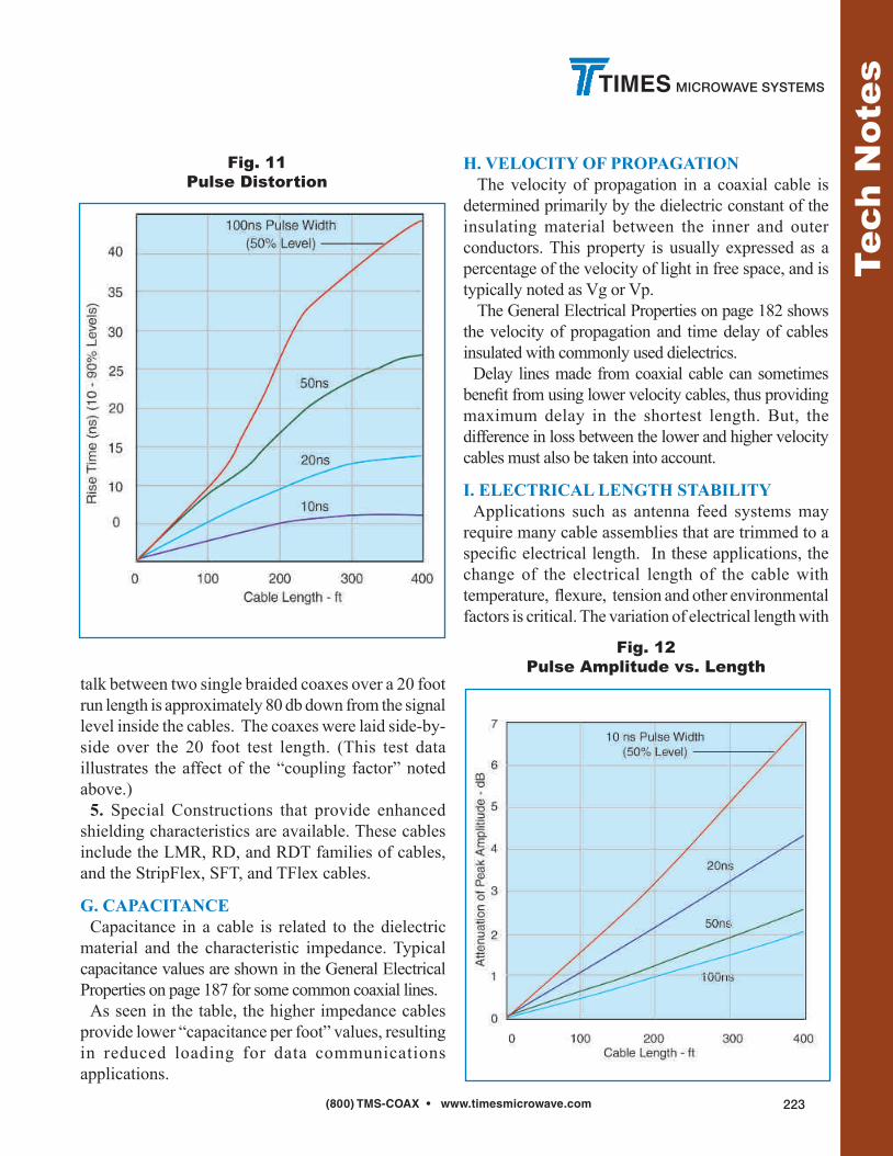
talk between two single braided coaxes over a 20 foot run length is approximately 80 db down from the signal level inside the cables. The coaxes were laid side-by- side over the 20 foot test length. (This test data illustrates the affect of the “coupling factor” noted above.) 5. Special Constructions that provide enhanced shielding characteristics are available. These cables include the LMR, RD, and RDT families of cables, and the StripFlex, SFT, and TFlex cables.
G. CAPACITANCE Capacitance in a cable is related to the dielectric material and the characteristic impedance. Typical capacitance values are shown in the General Electrical Properties on page 187 for some common coaxial lines. As seen in the table, the higher impedance cables provide lower “capacitance per foot” values, resulting in reduced loading for data communications applications.
H. VELOCITY OF PROPAGATION The velocity of propagation in a coaxial cable is determined primarily by the dielectric constant of the insulating material between the inner and outer conductors. This property is usually expressed as a percentage of the velocity of light in free space, and is typically noted as Vg or Vp. The General Electrical Properties on page 182 shows the velocity of propagation and time delay of cables insulated with commonly used dielectrics. Delay lines made from coaxial cable can sometimes benefit from using lower velocity cables, thus providing maximum delay in the shortest length. But, the difference in loss between the lower and higher velocity cables must also be taken into account.
I. ELECTRICAL LENGTH STABILITY Applications such as antenna feed systems may require many cable assemblies that are trimmed to a specific electrical length. In these applications, the change of the electrical length of the cable with temperature, flexure, tension and other environmental factors is critical. The variation of electrical length with
Fig. 11Pulse Distortion
Fig. 12Pulse Amplitude vs. Length

(800) TMS-COAX • www.timesmicrowave.com224
TIMES MICROWAVE SYSTEMS
A guide to the selection of RF coaxial cable
Tech
Not
es
temperature for standard flexible cables is shown in Figure 10. For polyethylene insulated cables:-100 to -250 parts per million/oC. For TFE insulated cables:-50 to -100 parts/million/oC. The variation of electrical length with temperature for the standard foam dielectric semiflexible cables is -20 to -30 parts/million/oC. Times has special flexible and semiflexible cable designs with improved electrical length versus temperature characteristics. Semiflexible cables having an electrical length change with temperature as low as five parts/million per degree centigrade are available. See SFT and Coppersol Low Loss CLL cables.
J. CUT-OFF FREOUENCY The cut-off frequency of a coaxial cable is that frequency at which modes of energy transmission other than the Tranverse Electro-Magnetic (TEM) mode can be generated. It does not mean that the TEM mode becomes highly attenuated. This frequency is a function of the mean diameter of the conductors and the velocity of propagation of the cable. The higher modes are only generated at impedance discontinuities and in many situations the cable can be operated above the cut-off frequency without substantial VSWR or insertion loss increase. However, it is recommended that cables not be operated above their cut-off frequency.
K. PULSE RESPONSE OF COAXIAL CABLES1. The following characteristics must be considered when analyzing the Time Domain response of cable to pulses or step functions: a: Impedance and Reflection; b: Rise Time; c: Amplitude; d: Overshoot or Preshoot; e: Pulse Echoes.a: Impedance and Reflection1. Select impedance to match system requirements.2. The impedance will vary along the length of cable. Variations of +5% are not uncommon. Cables can be
produced to tolerances of 2%. Tighter tolerances are not recommended.b: & c: Rise Time and Amplitude1. The output rise time is a function of input rise time, pulse width and cable attenuation. A typical pulse response is shown in Figures 11 and 12, while a typical step response is shown in Figure 13. Increased cable temperature causes an increase in rise time and decrease in amplitude.d: Overshoot or Preshoot1. Figure 13 shows the overshoot which can be encountered with a 0.1 ns input pulse rise time in cables due to finite reflections. Such overshoot is not common in cables with longitudinally extruded dielectrics.2. Preshoot is encountered in some balanced delay lines and can be minimized by cable design.e: Pulse EchoesWhen a narrow pulse is placed on a cable, the distortions noted above will occur. In addition, a small pulse of energy may emerge after the initial pulse has arrived. This pulse echo is caused by finite periodic reflections within the cable. Normally the echo level can be neglected.
L. SELF-GENERATED CABLE NOISE
Fig. 13Step Response
(Output Amplitude vs. Time)

(800) TMS-COAX • www.timesmicrowave.com 225
TIMES MICROWAVE SYSTEMS
Tech
Not
es
A noted cable phenomenon, is the generation of accoustical and electrical noise when flexed. The acoustical noise is a function of mechanical motion within the cable. Such noise (and the associated mechanical and frictional force) is minimized by proper cable design. Electrical noise generation is attributed to an electrostatic effect, which in testing has exhibited more than 500 millivolts in RG cable. This noise voltage can be minimized by preventing motion between dielectrics and conductors or dissipating electrostatic charges between conductors and dielectrics with semiconducting layers. Low noise constructions must take into account the life expectancy and environmental conditions to which they are subjected. Times manufactures low noise cables for special applications.
M. OPERATING TEMPERATURE RANGE 1. The operating temperature range of flexible coaxial cable is determined primarily by the operating temperature range of the dielectric and jacketing materials. Note that only silver plated conductors are suitable for long term use at temperatures over 80 degrees C. 2. Operating temperature limits of the most commonly used dielectrics and jacket types are given in the following table:
N. FLEXIBILITY Coaxial cables with stranded center conductor and braided outer conductors are intended for use in those applications where the cable must flex repeatedly while in service. Cables with stranded center conductors will exhibit higher attenuation compared to cables with solid center conductors. In general, the higher the number of strands, the better the flexibility and the greater the increase in attenuation. Standard braided outer conductor constructions will withstand over 1000 flexes through 180° if bent over a radius 20 times the diameter of the cable. Flexible cables may be stored, and are normally shipped, on reels with a hub radius greater than 10 times the diameter of the cable. If a flexible cable is to be installed in a fixed, bent configuration, the minimum bend radius recommended is 5 times the cable diameter.
Tighter bends can be made. Special braid designs are available for improved flex-life. Coaxial cables with a tubular aluminum or copper outer conductors, commonly referred to as semi- flexible or semi-rigid cables, will not withstand more than ten 180- bends over a bend radius equal to 20 times the diameter of the cable. Semi-flex cables are normally shipped on reels having a hub radius of 20 times the O.D. of the cable. Semi-flex cables may be field bent for installation. The minimum recommended bend radius is equal to 10 times the O.D. of the cable. Cables bent on a bend radius of 5 times the O.D. of the cable may exhibit mechanical and electrical degradation.
Temperature Material Range
Polytetrafluoroethylene (PTFE) -75°C to + 250°C Polyethylene -40°C to + 85°C Foamed Polyethylene - 40°C to + 100°C Foamed or Solid Ethylene Propylene Jackets - 40°C to + l05°C Fluorinated Ethylene Propylene (FEP) -70°C to +200°C Polyvinylchloride (PVC) - 40°C to + 85°C Ethylene Chloro Trifluoroethylene (ECTFE) - 65°C to + l50°C Polyurethane -100°C to + 125°C Perfluoroalkoxy (PFA) -65°C to + 260°C Nylon -60°C to + 120°C Ethylene Propylene - 40°C to + l05°C High Molecular Weight Polyethylene - 55°C to + 85°C Crosslinked Polyolefin - 30°C to + 85°C Silicone Rubber -70° to + 200°C Silicone Impregnated Fiberglass - 70°C to + 250°C High Temperature Nylon Fiber - 100°C to + 250°C

(800) TMS-COAX • www.timesmicrowave.com226
TIMES MICROWAVE SYSTEMS
A guide to the selection of RF coaxial cable
Tech
Not
es
O. ENVIRONMENTAL RESISTANCE The life of a coaxial cable depends on many factors. The effects of ultra-violet exposure, high humidity, galvanic action, salt-water and corrosive vapors on the materials used are prime causes of cable failure. Resistance to flame must also be considered. The following guidelines apply: a. Sunlight:For low temperature cables exposed to sunlight (ultra-violet), the use of high molecular weight polyethylene, with a specific carbon black particle size, % by weight and particle distribution, is recommended for maximum life expectancy. Polyvinylchloride jackets exhibit a life expectancy of less than 1/2 that of properly compounded polyethylene. b. Humidity or water vapor can enter flexible cables through pin-holes in the jacket, at the connector, or by vapor transmission through the jacket. All materials exhibit a finite vapor transmission rate. For example, a ten foot length of cable with a polymer outer jacket exhibits a helium leak rate of approximately 10-4 cc/sec/ft. Even the least porous thermoplastics, such as FEP, do not offer a significant improvement. In airborne applications, the combination of finite vapor transmission rates and large temperature extremes cause condensation in cables. The moisture can collect in low areas causing corrosion or shorting of a connector. One method of preventing moisture accumulation in cables is to fill all voids with a moisture-proofing compound which will not harden with age. See LMR-DB and Imperveon Cables for additional data. Times also supplies hermetically sealed cable assemblies with leak rates of less than 10-5 cc/sec/ft. c . Salt-water Immersion-The electr ical characteristics of cable will be rapidly affected if the conductors are exposed to salt-water. Unless an immersion test is performed on the jacket, there is a good possibility of one pinhole per 1000 feet. Even if sufficient tests could be performed, damage during installation or damage from rodents normally will cause leakage. Pressure-tight, non-hosing cables capable of withstanding the pressure at the required cable depth can be recommended. d. Corrosive Vapors: The use of tin and silver coatings does afford some protection against corrosive
vapors. However, such protection is short-lived. For installation near salt-water or chemical plants, a filled cable such as LMR-DB or Imperveon is recommended. e. Underground Burial & Galvanic Action: Underground moisture which comes in contact with any cable metals, will cause rapid corrosion. Tubular aluminum outer conductors have been almost destroyed in 90 days. Therefore, any cables installed underground should have pinhole-free jackets. Since jacket damage due to installation techniques and rodents can occur, cables filled with a flooding compound should be used. For maximum reliability against rodents, a steel tape armor with over-jacketing is recommended. f. Flame Resistance: Cables have different degrees of flame resistance depending on the jacket and dielectric material. "Flame retardant" cables are cables having limited flame spread (propagation). PVC jackets offer some flame retardance, depending on the compound selected. Flame retardant jackets, which are actually within the flame, will burn. If the flame is removed, they will self-extinguish. PVC jackets will not drip burning material. However, if the dielectric is polyethylene, the dielectric may drip ignited materials. PTFE and FEP will not support combustion, drip or burn. TMS has a series of Low Smoke / Low Toxicity cables to provide the utmost in protection. These cables utilize a proprietary TMS compound which is non-halogenated and produces combustion products that are low smoke and low toxicity. See the LSSB/LLSB, LMR-FR and M17 qualified cable lines.
P. CABLE STRENGTH The break strength of the cable depends primarily on the strength of the outer conductor. The cables will normally achieve at least 70% of the break strength of the outer conductor, if the center conductor will stretch up to 10% before breakage. Caution must be taken with cables with copper-covered steel or alloy center conductors where breakage would occur with only 1% to 10% elongation. Conductor sizes less than 26 AWG can easily be broken during assembly operations. Special alloy conductors are available which can

(800) TMS-COAX • www.timesmicrowave.com 227
TIMES MICROWAVE SYSTEMS
Tech
Not
es
achieve a tensile strength of 110,000 psi and 10% elongation.
Q. QUALIFICATION APPROVAL Often, cables must be qualified to certain standards to allow usage in particular applications. Typical examples of necessary qualifications are: Military: Most military applications require that cable conform to particular specifications. Many of these specifications require the manufacturer to qualify product by conducting a series of tests on a length of cable with a military representative present as a witness. MIL-C-17, the basic specification for most coaxial cables, requires a Qualified Products List (QPL). TMS maintains numerous MIL-C-17 qualifications. Commercial (UL) Approval: The building codes of many cities require that cables installed in their buildings be approved by the Underwriters Laboratories (UL). With UL service, the cable is subjected to a clearly defined series of tests and examinations, and has met the quality and safety standards imposed by Underwriters Laboratories. Approval of new designs meeting UL standards
normally can be made in a relatively short period of time. A large variety of TMS products are UL approved. New York State Requirements: Article 15, Part 1120 of the New York State Uniform Fire Prevention and Building Code requires that materials used in some buildings and transit systems be tested and registered with The New York Department of State. For the TMS products tested, the fire/gas/toxicity data is found in: DOS file number 16120-931203-4001. London Underground Limited: TMS has gained LUL approval on a series of low-smoke cable constructions. These cables were tested for smoke emission, toxic fume emission, and flammability assessment against the requirements of the London Underground Code of Practice for fire safety. Contact your TMS representative for more informa-tion regarding TMS product qualifications. MSHA Approvals: TMS has qualified the complete range of LMR-FR coaxial cables (file number 07-KA070010-MSHA-P) and T-RAD-FR leaky feeder cables (file number 07-KA07009-MSHA-P) to the MSHA flame requirements. Contact your TMS repre-sentative for further information.