timers - page 1/20 - timer products. timers - page 2/20 - multitechnology processing actuating...
TRANSCRIPT

Timers - PAGE 1/20 -
Timer Products

Timers - PAGE 2/20 -
Multitechnology
PROCESSING
ACTUATING
SENSING
COMMUNICATING
COMMUNICATING
PROCESSING
SOLUTIONS
Timers - PAGE 3/20 -
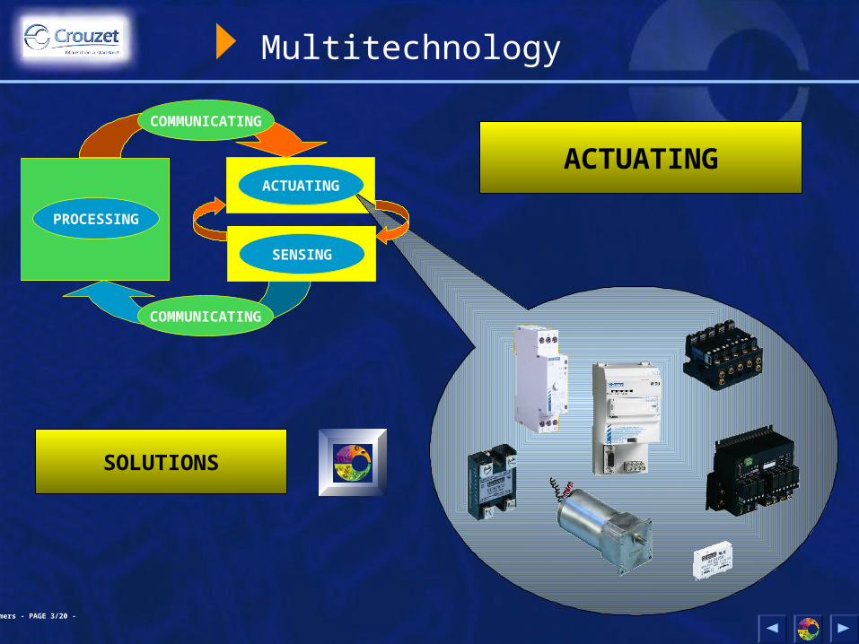
Multitechnology
PROCESSING
ACTUATING
SENSING
COMMUNICATING
COMMUNICATING
ACTUATING
SOLUTIONS
Timers - PAGE 4/20 -
Processing
Timers
Cam timers

Timers - PAGE 5/20 -
Timers
Basic technical concepts
Products
The competition
Timers - PAGE 6/20 -
Basic technical concepts
Operating principle
A timer is an automation control component which is designed toenergise an output contact during a precise timing cycle.It is also known as a “time delay relay”, “specified-time digital relay”or even an “electronic timer”.
The timing cycle starts when either power is applied to the timer or with an initiate switch. The timer model determines whether an initiateswitch is required. The delay on make time function in a Chronos 2will begin as soon as the power is applied. With the 88 857 series(TOP 948), an initiate switch is required.
Initiate switches can also be either a maintained or impulse (momentary)type contact.
Because of these options, there are a large number of potential timingfunctions and products.

Timers - PAGE 7/20 -
Basic technical concepts
Operating principle
There are 4 types of timers are available:
“DIN-rail mounted” products designed to be mounted to a standard 35 mm DIN-rail inside a wall-mounted or floor-standing enclosure.
“Panel mounted” products designed to be mounted on the front of a control panel for easy access by the user.
“Plug-in” products designed to be used with an industry standard8 or 11 pin socket. The socket can mount on a DIN-rail or surfacein an enclosure.
“Surface mounted” products designed to be mounted to a surface inside a enclosure.

Timers - PAGE 8/20 -
Basic technical concepts
Operating principle
Timing functions require a time reference to ensure the accuracy ofproducts.This time reference is known as the “time base”
The time base is obtained using one of two technologies:
- Electromechanical: The time base is obtained from a synchronousmicromotor whose speed depends solely on the frequency of themain supply on which it is connected.This motor, associated with a gearbox, controls contacts, usuallymicroswitches.
- Electronic: Several techniques are used: analogue or digital(counting) to obtain the time base.The output component is usually an electromechanical relay.Solid-state outputs are also possible.

Timers - PAGE 9/20 -
Basic technical concepts
Example of a timing function
Timing functions on Crouzet products are designated by aletter of the alphabet.
EXAMPLE: FUNCTION “A”
Delay on energisation.
Time delay
10
10Command
Output

Timers - PAGE 10/20 -
Basic technical concepts
Example timing function
EXAMPLE: FUNCTION “C”
Delay on break (delay off).
10Initiate - C, Y1
10Power - U
Time setting
10
Output - R1, R2

Timers - PAGE 11/20 -
Catalogue products
Chronos 2 electronic timersElectronic with relay output8 or 11 Pin plug-in or 22.5 mm or 17.5 mm DIN-rail
Timers - PAGE 12/20 -
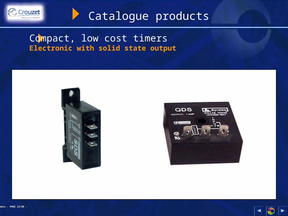
Catalogue products
Compact, low cost timersElectronic with solid state output

Timers - PAGE 13/20 -
Catalogue products
Panel mounted timersDigital electronics

Timers - PAGE 14/20 -
Catalogue products
Panel mounted timersAnalog electronic
Timers - PAGE 15/20 -
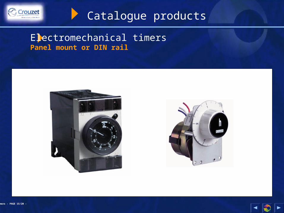
Catalogue products
Electromechanical timersPanel mount or DIN rail

Timers - PAGE 16/20 -
Catalogue products
Delay on make timersNAR2, relay output, 2-1/4” snap trackRTM, 4 relay outputs, PCB or DIN rail mount

Timers - PAGE 17/20 -
Competition: Timers
INTERNATIONAL COMPETITORS
1 OMRON
2 C GAVAZZI
1 SSAC
2 OMRON
3 IDEC
COMPETITORS (UNITED STATES)

Timers - PAGE 18/20 -
The main markets
Other activity sectors
Electrical equipment panel-builders
Home automation
Health
Machines
Vending/cash machines
Office automation
Defence/Aerospace
Household electrical goods
Automotive and onboard

Timers - PAGE 19/20 -
Applications
General
Timer controls can be used in addition to a programmable controller (or PLC) or in places where a programmable controller is not necessary. The requirement can be as small as one input and one output. Two outputs are also available on some products.
Combinations can also be used for more complex functions.

Timers - PAGE 20/20 -
Applications
Type of Business
- Printing Presses- Automatic Carwash- Machine Shop Equipment Manufacturers- Chemical or Petrochemical Plant Equipment- Swimming Pool Circulation and Filtering System- Manufacturing Plants with Automatic or Semi- automatic Equipment.- Injection Molding Equipment- Sawmill or Wood Cutting Equipment- Fabrication and Machine Shops that Specialize in Automation Equipment- Engineering Firms that Design Automation Equipment- Equipment Manufacturer’s for Electronic and Semiconductor Equipment- Furnace and Oven Manufacturers

Timers - PAGE 21/20 -
Applications
Specific Functions
- Alarm light or horn before automated equipment starts.
- Delay on Break timer to set length of horn.
- Repeat cycle (equal on/off) for flashing light.
- Alarm for operation that does not occur within a specific time limit.
- Automatic Greaser for bearing system
- Cooling fluid control for cutting tool.
- Conveyor operation
- Automatic door opening system.
- Timing control for injection molding machine
- Control for electrically operated valves.

Timers - PAGE 22/20 -
Cam timers
Basic technical concepts
Products
The competition

Timers - PAGE 23/20 -
Basic technical concepts
Operating principle
A CAM TIMER is an automation control component designed to actuatea series of contacts in a predetermined order during a cycle,according to a cyclical program.
The cycle can be: single-shot, repetitive, or step-by-step.
Often underrated, cam timers can be used to simplify automationsystems considerably and eliminate the need for manycomponents.

Timers - PAGE 24/20 -
Basic technical concepts
Operating principle
Cam timers consist of:
- A drive device: synchronous geared motor
- Data carriers: standard, adjustable (programmable), or precut striker cams
- Output switching components: microswitch (electrical) or microvalve (pneumatic)
Standard Programmable Custom

Timers - PAGE 25/20 -
Adapted products
There are numerous possibilities when creating camtimers.- Switching possible with 1 to 40 circuits- Possibility of complex cycles with 2 motors- Assembly of microswitches and microvalves- Etc

Timers - PAGE 26/20 -
Competition: Cam timers
COMPETITORS
1 SAIA
2 FIBER
3 CDC

Timers - PAGE 27/20 -
The main markets
Other activity sectors
Electrical equipment panel-builders
Home automation
Health
Machines
Vending/cash machines
Office automation
Defence/Aerospace
Household electrical goods
Automotive and onboard

Timers - PAGE 28/20 -
Timer Products
The CROUZET offerEND
THANK YOU FOR WATCHING