timed broadcast via off-the-shelf wlan distributed coordination
TRANSCRIPT

Aalborg Universitet
Timed Broadcast via Off-The-Shelf WLAN Distributed Coordination Function for Safety-Critical Systems
Malinowsky, B. ; Grønbæk, Lars Jesper; Schwefel, Hans-Peter; Ceccarelli, A.; Bondavalli, A.;Nett, E.Published in:Proceedings of Ninth European Dependable Computing Conference - EDCC 2012
DOI (link to publication from Publisher):10.1109/EDCC.2012.26
Publication date:2012
Document VersionPublisher's PDF, also known as Version of record
Link to publication from Aalborg University
Citation for published version (APA):Malinowsky, B., Grønbæk, L. J., Schwefel, H-P., Ceccarelli, A., Bondavalli, A., & Nett, E. (2012). TimedBroadcast via Off-The-Shelf WLAN Distributed Coordination Function for Safety-Critical Systems. InProceedings of Ninth European Dependable Computing Conference - EDCC 2012 (pp. 145-155). IEEE.https://doi.org/10.1109/EDCC.2012.26
General rightsCopyright and moral rights for the publications made accessible in the public portal are retained by the authors and/or other copyright ownersand it is a condition of accessing publications that users recognise and abide by the legal requirements associated with these rights.
? Users may download and print one copy of any publication from the public portal for the purpose of private study or research. ? You may not further distribute the material or use it for any profit-making activity or commercial gain ? You may freely distribute the URL identifying the publication in the public portal ?
Take down policyIf you believe that this document breaches copyright please contact us at [email protected] providing details, and we will remove access tothe work immediately and investigate your claim.

Timed Broadcast via Off-The-Shelf WLAN Distributed Coordination Function forSafety-Critical Systems
B. Malinowsky†, J. Grønbæk†, H.P. Schwefel†‡
‡Dept. of Electronic SystemsAalborg University, Denmark
†FTW, Wien, Austria{malinowsky,groenbaek,schwefel}@ftw.at
A. Ceccarelli, A. BondavalliUniversity of FirenzeViale Morgagni 65
I-50134, Firenze, Italy{andrea.ceccarelli, bondavalli}@unifi.it
E. NettUniversity of Magdeburg
Universitätsplatz 2D-39106, Magdeburg, DE
Abstract—Low cost wireless solutions for safety-critical ap-plications are attractive to leverage safety-critical operationin new application areas. This work assesses the feasibility ofproviding synchronous and time bounded communication tostandard IEEE 802.11 devices with low effort modifications. Anexisting protocol for time bounded communication in wirelesssystems is adapted to a generic safety-critical applicationwith low bandwidth requirements, but strict bounds on timebehavior. Experimental and simulation studies are conductedin which the protocol is implemented on top of IEEE 802.11eDistributed Coordination Function (DCF). The experimentalresults for packet loss ratio, communication delays, and broad-cast completion are used to calibrate a stochastic simulationmodel that allows to extrapolate the expected long-term per-formance of the protocol. Both the experimental results andthe simulation extrapolation show that necessary availabilityrequirements can be met with 802.11e prioritization in theinvestigated cross-traffic and interference scenarios.
Keywords: Safety-critical, Synchronous protocols,TDMA, 802.11e DCF, Experimental & Simulation
I. INTRODUCTION
Developing cost-efficient wireless communication solu-tions for high dependability and safety applications is at-tractive to 1) enable safety-critical automation for scenarioswhich currently rely on manual processes such as assistedvehicle driving and 2) to replace existing (wired) automationsystems which lack flexibility in installation and are poten-tially too costly to deploy widely. An example case of thelatter is presented in this paper considering an automatedalerting system for railway workers utilizing wirelesslyconnected personal devices to issue alerts about approachingtrains.
Wireless communication link reliability depends on theactual distances between the nodes, which varies in mobilesettings, on the presence of obstacles, and on possibleinterference from other transmitting devices or noise sources.When transmitting on a shared communication medium,with a possibly unbounded number of participating nodesand various procedures for channel access, timing faults haveto be accepted. Executing critical distributed services and
achieving the required reliability, safety and timeliness ofthe communication through portable and wireless devices inharsh environments requires the design of resilient servicesand networks [1], [2].A driver for wireless communication solutions has in
the past decade been the IEEE 802.11 standard. Todayit represents the de-facto technology to enable ubiquitouswireless access solutions for private and enterprise users.However, the standard is now also defining the basis fornew automation solutions such as wireless communicationinfrastructure for intelligent transportation systems 802.11p[3] and is intended for data collection, monitoring andcontrol in industrial applications.In general, low cost solutions based on IEEE 802.11
are manufactured primarily with focus on performance.Thus, integral features needed for high dependability andsafety are lacking such as synchronous and time boundedcommunication. How to provide such properties in wirelesscommunication is a well studied topic, see [4]. However,many existing solutions require low level modifications tohardware and software which increases cost.In this work, a practical approach is taken to evaluate
a timed reliable communication solution operating on topof the standard 802.11 protocol stack with off-the-shelfhardware. The approach entails:
• Use the Distributed Coordination Function (DCF), acarrier sense multiple access with collision avoidancetechnique for sharing the channel among multiplenodes, in addition to the widely available 802.11e formedium access priority control.
• Use an existing reliable group communication proto-col, and adapt its assumptions and properties (validity,agreement, integrity, ordering) to our use-case scenario.
• Evaluate communication reliability and performance inan experimental study with and without contendingnodes.
• Develop a stochastic simulation model of the protocolfor a feasibility analysis to extrapolate the results, andassess expected long-term protocol behavior in a fullscenario setup.
2012 Ninth European Dependable Computing Conference
978-0-7695-4671-1/12 $26.00 © 2012 IEEE
DOI 10.1109/EDCC.2012.26
144
2012 Ninth European Dependable Computing Conference
978-0-7695-4671-1/12 $26.00 © 2012 IEEE
DOI 10.1109/EDCC.2012.26
144

The protocol is intended to operate in the context of theALARP (A railway automatic track warning system basedon distributed personal mobile terminals [5]) project, wherereal-time and safety-critical communication is required totransmit information to wireless devices carried by rail-way trackside workers. The wireless communication layerneeds to deliver both life-critical messages (in particular,notification of trains approaching the worksite), as well asnon-life critical messages. The protocol presented in thispaper is devised starting from the ALARP requirements anda previous protocol, the Real-time Group CommunicationProtocol (RGCP, [6] [7]).
The paper is organized as follows: Section II introducesthe use-case of the alert system for railway workers, andpoints out the key requirements driving the communicationprotocol design. That section also provides the backgroundon the IEEE 802.11 Distributed Coordination Function(DCF) protocol and channel access prioritization optionsusing IEEE 802.11e. Section III introduces the synchronouscommunication reference protocol, and describes the adap-tations of this protocol to the ALARP scenario. The experi-mental and model based evaluations of the modified protocolrealization are introduced in Section IV to assess its mea-sured and expected performance. This part also constitutesthe focus of this paper. Finally, Section V concludes theresults and provides an outlook to future safety-orientedanalysis of the protocol.
Related Work: Several approaches exist for applyingQuality of Service (QoS) for real-time communication inIEEE 802.11 networks. Reference [8] evaluates differentschemes, also covering techniques for low latency real-timecommunication like Blackburst [9], which requires jammingthe wireless medium. Also, new software-based time slotscoordination mechanism were proposed [10], with the maintarget being Voice-over-IP communication [11].
II. SAFETY-CRITICAL COMMUNICATION SCENARIO
This section introduces the safety-critical communicationscenario, which guides our further studies of experimentaltest setups and developing our simulation models. The sce-nario covers the safety of railway workers at work sites nearrailway tracks, which can be easily generalized to similarsetups. Hence, the motivation of studying such use-cases isnot limited to railway-specific scenarios.
Safety of workers in railway scenario is a serious concern,since vehicles are constrained to tracks and drivers havemuch less margins to react in case of emergencies; therefore,trackside workers are exposed to injuries and fatalities [12],[13]. The ALARP [5] project proposes to design, developand validate an Automatic Track Warning System to improvethe safety of trackside workers. This system will be ableto inform the trackside workers about approaching trainson the track. Additionally, it will keep track of the status
and position of the workers, to identify those at risk, notresponding, or to suggest escape routes [14], [15].The ALARP architecture is based on the following
components realized on top of Commercial Off-The-Shelf(COTS) hardware: i) the trackside Train Presence AlertDevice (TPAD), able to sense an approaching train onthe interested track without interfering with the signalingsystem, using long-range multi-spectral cameras and eaves-dropping the train-network communication, ii) a set of dis-tributed, low-cost, wearable, context-aware, robust, trustableand highly reliable, wireless Mobile Terminals (MTs) toinform the workers about possible approaching trains and/orother events that could put at risk their safety, and iii)infrastructure for wireless communication. The MT will beable to generate alarms, and to communicate and interactthrough wireless connections with other MTs and the track-side train presence alert devices [14], [15].High reliability, timeliness and safety, despite the possible
harsh conditions are mandatory requirements of the ALARPcommunication, as alarms raised by the TPAD are safety-critical messages that need to be timely delivered to all theworkers. For safety reasons, violations of timing boundswill have to be detected and will (after remediation actions)finally lead to sending subset of workers to safe zones; thiswould impact the working procedures leading to loss ofproductivity.
A. Communication Architecture
The overall communication architecture in ALARP fol-lows a centralized communication setup. This enables betterpredictability of the communication timing and simplifiedrealization of synchronous communication channels at theworksite, see Figure 1. This setup is primarily based ona fixed coordinator located at the worksite, with all MTscommunicating via the coordinator [14]. The deployed timedreliable wireless communication protocol is using the coor-dinator to implement its centralized communication algo-rithm and maintain allocation of necessary communicationresources. Communication links between TPAD and theworksite might be enhanced by helper infrastructure in formof additional relay nodes (or repeaters) at the transmissionpath. At the worksite, TPAD information is disseminated toMTs via the coordinator.The overall communication solution maintains the com-
munication layer (of the MTs and TPADs) in a known com-munication state. It also adheres to safety requirements, andtimely decides on missing nodes as well as nodes deviatingfrom the expected operation behavior, enforcing communi-cation timeouts. The process of sending and delivering amessage is bounded by a maximum time delay requirement;typical values are in the order of several seconds. In ALARP,this time requirement is set to 10 seconds.The communication protocol adopted in ALARP shall al-
low the communication layer to reliably distribute messages.
145145

Worksite
802.11 b/g/n Access Point
TPAD HUB(x86 based)
100 Mbit/s Ethernet
MainCoordinator
Train Presence
Alert Device
TPAD Node
Max 700m
Max
50m
Mobile Terminal 1
(MT1)
MT2
MT3TPAD I(x86 based) TPAD II
(x86 based)
MTn
Train Presence
Alert Device
Figure 1. Communication architecture of the alert system for railwayworkers: workers are equipped with a Mobile Terminal (MT).
It offers broadcast (distribution to all nodes), multicast (one-to-many communication), and unicast (message exchangebetween two dedicated nodes) communication primitives.The reliability requirement is defined to match three differ-ent message criticalities, coming with a specific resiliencedegree for messages and probability of message delivery.For this, the communication layer offers the three criticalitylevels, or message classes: high for safety-critical messages(life-critical messages as notification to the workers of atrain approaching the worksite, health problems of a worker,etc.), medium for messages which are not safety-critical butif not timely received may affect system availability (e.g.,the message which notifies that a dangerous situation endedand work can restart), and low for messages with no specialrequirements (best-effort messages, e.g., the message an MTtransmits to notify all MTs that it is being switched off byits user).
In the following sections, we focus on the timed reliablebroadcast approach that is operated between the coordinatorand all MTs over COTS Wireless Local Area Network(WLAN) technology.
B. Background on 802.11 Coordination Functions
The IEEE 802.11 standard specifies two channel accesscoordination functions, the Distributed Coordination Func-tion (DCF), and the Point Coordination Function (PCF),summarized in the following.
Distributed Coordination Function: WLAN 802.11uses a carrier-sense multiple access scheme with collisionavoidance on the Media Access Control (MAC) layer, asublayer of the Open Systems Interconnection (OSI) modeldata-link layer (Layer 2). We here summarize the basicmechanism, see [16] for details. 802.11 nodes that have aLayer 2 frame ready to transmit, first sense the channel: ifit is idle for a certain time interval (referred to as Inter-Frame Space (IFS)), the fragment is transmitted immedi-ately. Otherwise, the nodes enter into a random backoffprocedure, where the backoff counter is chosen uniformlybetween two Contention Window (CW) bounds (CWmin
and CWmax), referring to the lower and upper bound,respectively. Values for the CW are given in slot time units,with the duration of a single slot specified by 802.11. Theupper bound is increased upon unsuccessful transmissions inorder to provide adaptivity to congestion levels, i.e., numberof contending nodes. Time periods during which the mediumis used by other nodes lead a node to temporarily pause itscount-down to access the medium. When the backoff counterreaches 0, the frame is transmitted and the sending nodelistens for an Acknowledgment (Ack) from the receiver. TheAcks are prioritized on the channel, as the medium accessprocedures are performed with lower IFS for those. If thesending node does not correctly receive an Ack in a certaintime interval, it assumes that the transmission has failed; itthen increases the upper bound (CWmax) for the backoffcounter, and retransmits the fragment with the same MACprocedure. This MAC DCF procedure is symmetric, allnodes implement it in the same way. Due to the symmetriccontention scheme, access delays vary and depend on thenumber of contending nodes as well as on transmissionerrors (due to the impact on backoff counter bounds).
Point Coordination Function: In order to make mediumaccess delays more predictable, a scheme called Point Co-ordination Function (PCF) has been defined as a part ofthe IEEE 802.11 specification. The access scheme uses thesame MAC procedures, but a coordinator (the access point)provides centralised medium arbitration, prioritizing channelaccess by utilizing shorter inter-frame spaces for part of thecommunication. With such higher prioritized frames, it pollsthe set of nodes for up-link data, i.e., data to be transmittedfrom a node to the access point. During that Contention FreePeriod (CFP), the access point grants exclusive access to themedium by transmitting a polling message to some node inthe set of nodes. Although this technique avoids contention,the problem of message losses still remains. Further detailscan be found in [17].
However, PCF does not provide strict time guaranteeson its CFP repetition interval and on delays for channelaccess with multiple PCF coordinators operating on the samechannel. Besides, PCF mode is nowadays seeing extremelylimited support by available COTS WLAN devices, makingit not the preferable choice.
An alternative is to implement the polling for mediumaccess coordination from the higher layer protocols; thesecond feature, prioritization of polling messages comparedto other DCF traffic, can then be achieved by utilizing fea-tures of the 802.11e standard. Two features are of particularinterest: 1) the use of different inter-frame spaces, and 2) themodification of bounds of random backoff intervals. Bothof these can be implemented via 802.11e mechanisms, see[18] for details. The way these are used in the experimentalimplementation is described in Section IV-A.
146146
III. THE TIMED RELIABLE COMMUNICATION PROTOCOL
This section presents the Timed Reliable Communicationprotocol (TRC), the real-time communication protocol wedesigned for 802.11 communication between devices withinthe ALARP worksite. This protocol is built by modifying theReal-time Group Communication Protocol (RGCP [6], [7]).After presenting the RGCP, the TRC protocol is described,in terms of changes applied to the RGCP protocol. Whilethe RGCP is based on the assumptions of 802.11 PCF, ouradapted protocol is targeted for use on top of 802.11 DCF,with the differences explained in Sections II-B and III-C.
A. The base protocol RGCP
The RGCP provides reliable and efficient group commu-nication services, relying on the IEEE 802.11 PCF and on acentralised coordinator (Access Point (AP)). The coordinatorschedules channel access for a group of nodes. The APgrants exclusive access to the medium by transmitting apolling message to some node in the group. Hence, theRGCP is based on the assumption of the PCF providingits contention free node slotting mechanism.
Before entering into details of the protocol we presentits assumptions and properties. The RGCP is based on thefollowing fault assumptions:
• Messages sent during the CFP are either lost (omissionfault), or are delivered correctly within a fixed time-bound tm. The losses may be asymmetric i.e., somenodes may receive a broadcast message and somemay not. The number of consecutive message losses isassumed to be bounded by a so-called Omission DegreeOD [19] that denotes an upper bound on the numberof omission faults that may affect a single message. Inthe case of a broadcast message, this means that afterOD + 1 transmissions every receiver has received atleast one of these transmissions.
• Nodes may suffer crash failures or, due to their mobil-ity, may leave the reach of the AP at arbitrary pointsin time (without crashing). This resembles a permanentcrash of the link between the AP and the leaving node.
• The AP is stable, i.e., not subject to any kind of error.
We here briefly discuss, and later analyze, the assumptionon the omission degree OD. Every protocol that intends toguarantee reliable transmission and real-time properties onan unreliable medium must base on this [6] or define a fault-detection procedure for fault coverage. OD in our settingcan be seen as a parameter that can be optimized in orderto address the following trade-off: i) selecting an OD largeenough to ensure that the coverage of the assumption onthe semantics of the omission degree is large enough, andii) minimizing the additional overhead created by an overlylarge choice of OD and assuring that the protocol can beexecuted within the required time-bounds.
The RGCP satisfies the properties of:
• Validity. If a correct station broadcasts a message mthen it eventually delivers m [20].
• Agreement. If a correct station delivers a message mthen all correct stations eventually deliver m [20]. Notethat validity together with agreement ensures that amessage broadcast by a correct station is delivered byall correct stations.
• Integrity. For any message m every correct stationdelivers m at most once and only if m was previouslybroadcast by its sender [20].
• Total order. If the messages m1 and m2 are deliveredby stations s1 and s2, then station s1 delivers messagem1 before message m2 if and only if station s2 deliversmessage m1 before m2.
The RGCP communication is structured into rounds. Dur-ing each round, the AP polls each node of the group exactlyonce. After being polled, a node returns a broadcast requestmessage to the access point, which assigns a sequencenumber to that message and broadcasts it to the node group.The broadcast request message is also used to acknowledgeeach of the preceding broadcasts by piggy-backing a bit fieldon the header of the request message. Each bit is used toacknowledge one of the preceding broadcasts.
By this, one round after sending a broadcast message,the access point is able to decide whether each groupmember has received the message or not. In the latter case,the access point will retransmit the affected message. Bythe assumptions made above, a message is successfullytransmitted after at most OD+1 rounds.
If the AP does not receive the request message within acertain period of time after polling the node, it considersthe request message (or polling message) to be lost, andtransmits the last broadcast message of the not respondingnode if it has not yet been acknowledged by all nodes. Ifthe AP does not receive the request message from a nodefor more than OD consecutive times, it considers that nodeto have left the group and broadcasts a message indicatingthe change in the group membership.
To enable the user to improve the timing guarantees,the parameter resiliency degree is introduced, to allow theuser specifying the maximum number of retransmissionsof the messages. This resiliency degree res(c) representsa bound on message retransmissions, which may vary fordifferent message classes c. A value res(c) smaller thanOD allows trading reliability of message transmission forshorter transmission delays.
The modification introduced in the protocol to considerthe resiliency degree are as follow. If a message m isacknowledged by all nodes after at most res(c) + 1 rounds,the AP issues the decision to deliver m to the applications,through the broadcast of a decision message, which is re-transmittedOD+1 consecutive times (to guarantee receptionby all correct nodes). If, however, the AP does not receivethe acknowledgement of any node after res(c) + 1 rounds,
147147

a decision not to deliver m is issued, again through thebroadcast of a decision message.
It can be noted that the introduction of the resiliencydegree brings advantages of shorter delivery time for amessage, obtained by reducing the maximum number ofretransmissions for a broadcast message to res(c) times,but comes at the cost of violation of the validity property.Now, a message requested to be broadcast by a correctnode may not be received by all the other nodes andtherefore not delivered. However, the agreement, integrityand total ordering properties are retained (total ordering andagreement are preserved thanks to the introduction of thedecision message).
B. The Timed Reliable Communication (TRC) protocol
The TRC protocol for communication within the worksiteis presented by showing modifications and differences w.r.tthe RGCP (with resiliency degree) that were applied to fit theALARP requirements. Three key modifications are identifiedand described in what follows.
Modification 1. In ALARP there is no need to guaranteetotal ordering and agreement. Regarding total ordering, it isnot required that the broadcasted messages are delivered ac-cording to a total order because each message is independentfrom the others.
Regarding agreement, in ALARP a message may not bedelivered to all correct nodes. In fact, each node of theworksite contains its own means to detect the potential lossof critical messages, and react accordingly (e.g., by usingtimeouts to detect message loss and by safely notifying tothe worker the potential hazardous condition due to suchloss). Moreover, as soon as a node receives a message, itcan start to process it. This implies, that two different nodescan have an inconsistent view of the ALARP system at agiven point in time.
Consequently, the TRC protocol relaxes agreement andordering properties by removing the decision message, thatis no more transmitted by the AP. This further shortens thedelivery time of a message.
Modification 2. While RGCP is intended only for broad-cast, in ALARP reliable broadcast, multicast and unicastare required. The TRC protocol introduces unicast andmulticast using a scheme very similar to broadcast. In caseof multicast, the procedure is the same but a polled nodeneeds to: i) specify that it wants to transmit a multicastmessage, and ii) transmit the multicast mask, which enliststhe recipients of the multicast. In case of unicast, once polledby the AP, a node simply needs to reply that it has a unicastmessage for a specific recipient Y .It is important to note that introducing multicast and
unicast requires to further extend the header of the mes-sages, to include the additional information needed (therecipient of the unicast message, or the multicast mask).This modification also requires to further extend the logic
of the AP. In the RGCP, each messages is retransmitteduntil it is acknowledged by all nodes (or the bounds onallowed retransmissions are reached). This requires that theAP simply needs to collect acks from all nodes. Insteadin TRC, to define the delivery status of each message, theAP needs to remember if the acknowledged message is aunicast, multicast or broadcast (and the intended recipients),and define accordingly the delivery status of the message.
Modification 3. The formulation of the RGCP introducesthe resilience degree res(c) for different reliability classes,and actually consider the possibility of using different mes-sages classes (reliability levels); however this is not appliedexplicitly in the usage of the protocol in [6], [7]. Theresiliency degree res(c) in ALARP is set to three differentvalues that match the three corresponding message classesintroduced in Section II-A:
1) Level high = res(high);2) Level medium = res(medium);3) Level low = res(low).
It is expected that res(high) ≥ res(medium) ≥ res(low).Information on the message level has to be communicated
by the broadcasting node (after receiving the poll from theAP), by properly extending the header of the message.
Table I summarizes the main differences between TRCand RGCP.
Table ICOMPARISON OF RGCP AND TRC.
RGCP TRC(with res(c))
Provides Validity no noProvides Agreement yes noProvides Integrity yes yes
Provides Total Ordering yes noAccepts levels of reliability yes yes
for message deliverySupports Broadcast yes yesSupports Multicast no yesSupports Unicast no yes
C. TRC Protocol Modifications for DCF
The TRC protocol for the ALARP system is based on802.11 DCF, and not PCF mode as the base RGCP. Thisrequires additional TRC functionality, because the proto-col cannot rely on PCF contention free periods, built-inmaintenance of the node polling list, and the node pollingmechanism.
Therefore, the TRC coordinator is enhanced with a sched-uler which takes care of polling a defined set of nodes forthe required protocol time-slotting, similar to PCF. Withina protocol slot, the coordinator’s poll packet or the node’srequest packet can be lost, or a node might not reply atall. To cover those cases, an additional configurable intra-slot time parameter, the Poll-Request Failed Timeout (P+RFailed Timeout) is introduced. This parameter specifies thelongest time delay within one slot before the coordinator
148148

sends the broadcast packet. This ensures that even with afailed poll or request transmission, a minimum slot lengthis left to enable the broadcast packet to be sent.
DCF communication in a selected 802.11 channel willintroduce time delay of sending nodes due to the channelsensing and backoff algorithm in the presence of other con-tending nodes. Although the set of protocol communicationnodes (within one ALARP worksite) will be scheduled ac-cording to a predefined sequence known to the coordinator,and hence, will not contend, this does not hold for anyother node. With 802.11 DCF operating in a shared mediumand an a-priori unknown number of contending nodes inthe same channel, no upper time bound with transmissionguarantee is provided. To mitigate that serious drawback,TRC communication is prioritized as far as possible. Toget an advantage in terms of more aggressive access to thechannel, the TRC protocol is applying a Quality of Service(QoS) scheme of IEEE 802.11e. In particular, transmissionis using a shorter IFS and a lower CW_min setting.This conforms with our approach of avoiding any hardwareand low-layer driver software modifications. The detailedparameter settings are described in Section IV-A.
In summary, the DCF version of the timed reliable broad-cast protocol includes the following features:
• Explicit polling and maintenance of node membershipby additional AP software on top of WLAN Layer 2.
• Introduction of a timeout mechanism at the AP inorder to send broadcast messages within a slot despitemissing requests messages from the polled node.
The realization of the protocol on top of 802.11 uses thefollowing WLAN configuration settings:
• Prioritization of messages via shorter inter-frame spacesand shorter backoff window sizes using 802.11e.
• Deactivation of Layer 2 retransmissions in order toreduce the variability of Layer-2 transmission times.
The following evaluation section investigates to whatextent different parameter settings influence broadcast avail-ability and reliability of this extended approach. One im-portant aspect is the coverage of the OD assumption, whoseviolation is assumed to lead to a disconnect of the node. Theanalysis addresses the question, whether a time to disconnectcan be achieved which is in a feasible range of at leastseveral hours for realistic parameter choices and settings.
IV. EXPERIMENTAL AND MODEL STUDY
To evaluate the TRC protocol in an IEEE 802.11 DCFsetting both experimental and simulation-model based stud-ies have been conducted. The main objective of the studyis to characterize the protocol performance for the DCFrealization. The protocol is implemented in a testbed witha limited number of clients. From experimental results inthe testbed, the protocol behavior in a real-world scenariocan be established. An important part of this analysis is to
define how DCF channel contention aspects affect the in-slot packet delay characteristics. This characterization, in theform of transmission delay distributions, is then applied ina stochastic simulation model developed by the authors forthis purpose. Subsequently, this stochastic simulation modelenables extrapolated analysis to assess the expected long-term operation behavior of the protocol scaled to differentscenarios. In the following section the TRC protocol testbedrealization is described.
A. Protocol Realization
The TRC protocol implementation consists of two parts:one part is executed on a coordinator, and the other one ateach protocol communication node. The coordinator doesthe node polling and takes care of distributing the messagesas explained in the protocol description section. For theexperimental evaluation, only broadcast messages are dis-tributed, to delimit the analysis. The protocol performanceis evaluated by sending high-priority messages, i.e., usingthe highest resilience class. Here, a node is then defined tobecome disconnected when it cannot be reached after OD+ 1 rounds. Such disconnection cases are measured in theexperimental system and further analyzed in the simulationmodel.For realizing the coordinator, an 802.11 Access Point (AP)
is used. The main selection criterion for the AP is that itprovides an Atheros chipset for wireless communication;this chipset allows an easy configuration and adaption toour needs using an Open-Source driver implementation.The selected AP uses the Atheros AR9287-BL1A chipset,supporting b/g/n communication and having two externaldetachable antennas.The standard firmware of the AP has been replaced with
OpenWrt [21], a Linux distribution for embedded devices,using the latest trunk version. The adapted TRC protocol istargeted to run on the AP, and therefore implemented usingthe OpenWrt Linux application programming interfaces.Messages are sent as Internet Protocol (IP) packets usingLinux socket interfaces. The sources have been compiled toan OpenWrt package and installed on the AP.The communication protocol client nodes are executed
on a netbook and laptop, respectively, both running Debian,Kernel version 2.6.32-5. The external wireless communica-tion device uses a RALINK RT2870F chipset and is attachedvia USB cable to the computer.To ensure sufficient processor time slices, all protocol
process priorities are increased to the highest possible.For realizing TRC communication with 802.11e QoS,
both coordinator and client nodes have to support andenable the 802.11e Wi-Fi Multimedia extensions. An earlyexperimental communication test setup conducted in thebeginning of the tests have provided the appropriate setof 802.11e configuration values to compete in cross-trafficscenarios. Based on those results, the 802.11 Enhanced
149149

Distributed Channel Access (EDCA) category parameter isset to voice (AC_V O), with the Arbitration Inter FrameSpace (AIFS) to 1, and Contention Windows (CW) to 4(CWmin) and 7 (CWmax). The wireless communicationuses the 802.11b mode with a physical rate of 11MBit/s forall measurements (including both protocol member nodesand contending nodes for cross-traffic). Data-link layer re-transmissions are disabled on both the coordinator and clientside to mitigate time delay variations within one slot causedby the standard 802.11 binary exponential backoff algorithm;therefore, all retransmissions are performed via the TRCprotocol. Because the AP chipset does not allow to reset themaximum retransmission retry count to 0, all AP packets aresent as broadcast frames, thereby avoiding retransmissions.(Hence, with no retransmission, the CWmax value does notaffect channel access.) Re-enabling Layer 2 retransmissionin a future deployment does not affect TRC protocol func-tionality, but can adversely influence the intra-slot packetdelays. The TRC protocol parameter P+R Failed Timeout isset to 40ms.
B. Evaluation Approach and Metrics
The study of the protocol realized on DCF is taking astarting point in the execution of two scenarios: 1) No cross-traffic - the protocol is executed in an environment withlimited traffic (caused by a few distant access points) inthe same channel. This setting will provide a reference forthe protocol operation under good conditions. 2) With cross-traffic – other wireless nodes are introduced in the channelto contend heavily for the channel resources. This setting isrelevant to clarify the impact on the packet loss and messagedelay in scenarios when the TRC protocol will not haveexclusive channel rights.
Obtaining long-term behavior of the TRC protocol isimportant to establish the suitability of the protocol realiza-tion for the described application scenario. Obtaining suchassessments from an experimental setup is, however, timeconsuming and impractical as the execution conditions canbe difficult to control. Instead, a model of the protocol logichas been implemented in a MATLAB simulation model. Themodel uses packet loss rates ( PLR) and empirical trans-mission delay distributions estimated from the experimentalstudies. Subsequently, the model enables extrapolations ofthe measurement results to different protocol parameteriza-tions.
To characterize the communication channel properties andthe overall TRC protocol behavior, the following metrics aremeasured in the experimental setup:
Packet Loss Ratio (PLR): The packet loss ratiodescribes the ratio of packets lost in relation to transmissionattempts sent. The PLR is used as an estimate of the packetloss probability. The same packet loss probability is assumedfor each protocol packet sent, independent on whether it isa poll, request or broadcast. An estimate of PLR is defined
Contenting NodesSaturated transmissionNon-elastic traffic sourcesStandard DCF
0.3 m 0.3 m1 m
Main Coordinator
Protocol Member NodesPeriodic Broadcast802.11e (AC_VO’)
Channel 1Channel 1MT 1
MT 2
Figure 2. Experimental setup used for performance measurements
as PLRPR and is obtained from a statistic of failed poll-requests at the access point.
Poll+Request Transmission Time [ms]: This metricdescribes the time within a slot measured at the AP from themoment of sending a poll until receiving the correspondingrequest. The metric includes poll transmission time, pollprocessing time at a node and the request transmissiontime. The metric is calculated at the access point for eachsuccessful poll-request pair.
Request to BC Completion Delay (δRCDC) [ms]: Thisdelay characterizes the time duration from the moment thecoordinator (access point) has received a broadcast messagefor dissemination, until the time the access point has receivedan acknowledgment from all protocol member nodes. Hence,this metric assesses when the coordinator assumes a broad-cast to be completed and when it can continue to process anew message from the given source node.
Request to BC Reception Delay (δRRDD) [rounds]:The broadcast reception delay is a distributed measurementusing round numbers as granularity. It describes the delaymeasured in terms of number of rounds from when thecoordinator has received a broadcast message for dissem-ination, until the message has been received first time by allprotocol member nodes. As each broadcast message containsa retransmission number, this metric can be derived as adiscrete round time metric based on node and AP recordings.
C. Experimental Evaluation Scenario
The setup used for the experimental studies is introducedin Figure 2. It consists of two sets of communication devices:1) The devices implementing the TRC protocol given by theMain Coordinator access point and two Protocol MemberNodes and 2) a node set of contending nodes communicatingvia the AP. All nodes are operating in the same wirelesschannel (channel 1). Thus, the protocol member nodes mustcontend on the channel with the Contending Nodes.
150150

Table IIGENERAL EXPERIMENTAL EVALUATION SETTINGS.
Setting Value Setting ValueContendingNodes
2 Slot length 50ms
ProtocolMemberNodes
2 res(high)=OD 15
ExperimentDuration
30min Wireless Mode 802.11b
BC Payload 58 bytes PHY Rate 11Mbit/sBC FrameSize
92 bytes 802.11e setting:AC_VO’
AIFSN =1, CWmin =4 slot times,CWmax = 7slot times
The contending nodes are configured as standard DCFnodes (without 802.11e). These stereotypes are the mostcommon in existing deployments (in offices, homes etc.).In the cross-traffic scenario both nodes are running with asaturated transmission buffer constantly trying to transmit1506 byte frames to represent a worst-case load. It mustfurther be noted that all wireless devices are located in closeproximity. This means that signal conditions are good andthat most experienced losses can be attributed to collisionsand interference. Interference is likely, as the testbed setuphas been deployed in an office scenario with around 12 otheraccess points operating in the 2.4 GHz frequency band. Thechannel selected for the tests has been chosen such that itcontains the fewest other access points. Each experimentalexecution run takes 30 minutes.
Detailed information on the parameters used for theexperimental results are provided in Table II.
D. Experimental Results
The experimental results have been obtained from anexecution with and without cross-traffic. The access pointnotifies a protocol member node when its previous broadcasthas been completed in a poll. In the same slot, the nodeprepares and sends a new broadcast in the request. Withthis approach, a node performs only one broadcast at thetime, and we can thus disregard any queuing in the followinganalysis (although this aspect must be considered in futurework).
The overall outcome of the experiments is summarized inTable III. The main findings are:
• A high packet loss rate has been observed with cross-traffic enabled of almost 18%. This high increaseis mainly expected to stem from collisions with thecontending nodes. As no re-transmissions are enabledon layer 2, the node does not get the advantage ofimplementing a smaller contention window comparedto the contending nodes (which have retracted formthe medium as well) for a fast retransmission. Futurework should consider if 1-2 fast (Layer 2) retransmis-sions could provide an advantage without increasing
transmission delays significantly. Despite the high lossrate the protocol largely runs fine still. The simulationanalysis clarifies this aspect in more detail.
• Even for the case without cross traffic a substantial lossrate is observed of 3.5%. These losses may stem fromother interfering nodes in wireless neighbor channelsor hidden nodes.
• In the average case, the request to broadcast completiondelay increases by around 70ms for δRCDC for a nodewhen cross-traffic is activated.
• The maximum value δRRDD (worst case) in TableIII with cross-traffic OFF stems from the transmissionirregularities, where a nodes requires that many roundsto finally receive the broadcast.
• When studying the general protocol execution an ir-regularity has been identified in the communicationfrom the mobile nodes participating in the TRC. Theirregularity consists of a systematic transmission inter-ruption of 1 seconds, approximately every 60 seconds.The interruption is TRC protocol independent as it alsooccurs when running periodic message transmissionswith test tools (using mgen and wireshark monitoringtraces). This interruption is presumably a driver issuethat must be solved in future implementations. Theirregularity to a large extent does not influence themeasurement data for the processing of intra-slot delaymetrics. But it has an impact on BC reception delay,see further below.
• An impact of the node transmission irregularity can bestbe observed in relation to disconnects. Recall, that thecoordinator will consider a node to be disconnected if ithas not responded for OD+1 rounds. In the cross-trafficcase two of such disconnects have been observed. Theseare expectedly a result of the transmission irregularitythat can stop the node from responding for a largepart of a round. Together with the added delays andlosses from cross-traffic, this provokes disconnects.This is especially the case with a small set of nodesand small slot sizes, because a single irregularity willseverely affect the nodes ability to communicate withinthe protocol’s upper bound limit. For the similar runwithout cross-traffic, no disconnects are observed. Herethe redundancy of the protocol is sufficient to avoid theinterruption.
The effects of the cross-traffic scenario are best observedin Figure 3. It shows the distribution of the poll+requesttransmission times (and associated processing time). It isseen that in both cases, this message flow is completedwithin a few ms. Even for the cross-traffic case the transmis-sion times are far from the intra-slot timeout of 40ms. Thisaspect can partially be described by the aggressive channelaccess scheme applied through 802.11e and the fact that onlya single transmission is attempted. In normal DCF, eleven
151151

Table IIIEXPERIMENTAL RESULTS.
Experiment Parameter Value
Cross-traffic OFF
PLRPR 0.035Disconnects 0δRRDD (avg./max) 0.2/12 [rounds]δRCDC (avg./max) 117/1405 [ms]corresponding to 2.3/28 [slots]
Cross-traffic ON
PLRPR 0.177Disconnects 2 (Node 1)δRRDD (avg./max) 0.12/10 [rounds]δRCDC (avg./max) 188/1480 [ms]corresponding to 3.8/29 [slots]
0 10 20 30 40 500
2
4
6
8
x 10−4
Single slot [ms] (bin size 0.05 ms)
Distributions of Transmission Time in a Slot: Poll+Request
Without Cross−trafficWith Cross−trafficP+R Failed Timeout
Figure 3. Transmission time distributions for successful poll and requestmessage pairs in a 50 millisecond slot (joint over both nodes).
retries are standard, which in conjunction with increasingchannel backoff times can lead to excessive delays.
These results are encouraging to evaluate shorter slottimes. This aspect will be studied in the simulation modelevaluation which uses these delay distributions as an input.
Having established in Table III the fundamental settingsof the experimental results, the cumulative distribution func-tions in Figure 4 depict several interesting aspects regardingthe broadcast transmission delays. The upper figure showsthe case without cross-traffic. Considering initially δRCDC
(dark color), it is clear that most broadcasts (around 99%)are successfully completed after round 3. In practice, mostnodes have received the broadcast already in second round(in around 99% of the cases). All messages are successfullycompleted within the 16 (OD+1) rounds. This implies thatno disconnects are observed.
Studying the cross-traffic case in the lower part, it canbe observed that all nodes receive most broadcasts (around99%) already in round 3. However, only at round 9, thecoordinator has received all acknowledgements. This impactclearly stems from the increased packet loss rate. In thecross-traffic case, we observe that OD+1 has been exceededtwo times, i.e., two disconnects have been observed.
E. Simulation Based Results
In order to extend the observations of the experimentalresults, the TRC simulation model has been parameterizedfrom the experimental results. The parametrization has been
0
0.2
0.4
0.6
0.8
1
With
out C
ross
−T
raffi
c
CDF of Request to Broadcast Delay Times
Rounds until Broadcast ReceptionRounds until Broadcast Completion
0.99
0.995
1
1.005
0
0.2
0.4
0.6
0.8
1
With
Cro
ss−
Tra
ffic
Slots and Rounds [ms]20
040
060
080
010
0012
0014
0016
000.99
0.995
1
1.005
Slots and Rounds [ms]20
040
060
080
010
0012
0014
0016
00
Figure 4. Comparison of broadcast delays with (lower figures) and without(upper figures) cross-traffic. The gray color shows the time until broadcastreception at the MT, while the dark color shows the time until all Ackshave been received by the AP. The right part shows a zoom into the leftcurves. The curves show a step function with width of the steps equal tothe slot-time of 50ms, as the reception events are evaluated at the end ofeach slot.
based on the estimated packet loss ratios provided in TableIII, and the delay distributions of Figure 3. In the simulationmodel packet losses are assumed to be independent. Also,a broadcast is considered to be received by all nodes orno node at all, resembling the experimental test setup withspatially close nodes where packet losses are only resultingfrom collisions which affect all receiving nodes equally. Interms of transmission delays, the poll and request durationsare sampled from the empirical delay distribution within therange up to the 90 percent quantile. Both with and withoutcross-traffic, long tails have been observed in the measure-ments with delay samples up to 40ms in rare cases. Also,as the slot moves on with a broadcast after 40ms, longerdelays that may have occurred are not in the distributions.As these longer delays are important to simulate, the tailof this distribution has been fitted separately. To mimic thehigh variability, a 2-parameter Pareto distribution has beenfitted to match the largest 10% of the data of the empiricaldelay distribution. This fitted Pareto distribution is then usedin the simulations for the tail samples.
Regarding the parts of the delay distribution before thePareto tail, the experiments provide a delay distribution ofthe poll and request pair. To define a delay distribution forthe individual transmission of a broadcast, the followingassumption has been made: a poll and a request individ-ually experience delays sampled from an independent andidentically distributed shifted exponential (shifted as there
152152

0 200 400 600 800 1000 1200 1400 16000
0.2
0.4
0.6
0.8
1
Slots and Rounds [ms]
CDF comparing the Broadcast Request to Completion Delay Times
Measured Request to Completion Delay c−tSimulated Request to Completion Delay c−tMeasured Request to Completion DelaySimulated Request to Completion Delay
Figure 5. Comparison of experimental and model results of the broadcastrequest to completion delay.
is a minimum transmission delay). Thus, it is assumedthat the joint distributions is a shifted 2-stage Erlangian,and that the parameters of the exponentials can easily bedetermined via least square fitting. Combining this shiftedexponential sampling with the Pareto tail sampling, thesimulation model can now be executed with parametersmatching the experimental results.
Validation of simulation model: To assess the resultsfrom the simulation model in comparison to the experimentalresults, a comparison of the ’request to completion’ delayproduced by both is shown in Figure 5.
The results show generally a good correspondence be-tween the simulation model and experimental results. How-ever, in the cross traffic case the simulation model is gener-ally a little more optimistic. A part of the explanation maystem from the fact that packet loss ratios to the individualnodes are not completely alike and also not independentidentically distributed in reality (leading to some shifts intimes to when a broadcast can be considered completed).The simulation model does not capture this effect. Anotheraspect is the systematic transmission interruptions in thesimulation runs that make the tails a bit longer for theexperimental results compared to the model (which does notinclude these long transmission interruption delays). As wasobserved that the transmission interruption delays are notrelated to the TRC design and implementation on DCF, weconcluded that the slightly more optimistic model producesvalid evaluation results.
Extrapolation of results: Having parameterized thesimulation model, several extrapolation analysis experimentscan be conducted via the simulation. Most interesting isto clarify how the protocol will operate in scaled upscenarios (to match the scenarios introduced in SectionII) with more mobile terminals participating in the timedreliable broadcast. Further, the application-specific worst-case requirement for delivering a safety-critical message is10 seconds (Section II-A). According to the experimental
results above, an OD of 15 is sensible to the retransmissionattempts experienced, and makes it possible to toleratesignificant interruptions in the transmission – see Figure 4.This leads to analyzing shorter slot sizes below 50ms. Withthe TRC protocol worst-case execution time correspondingto 2×OD + 1 rounds, we analyze cases of:
• S1: 20 nodes, slot size = 15ms (P+R Failed Timeoutof 5ms)
• S2: 16 nodes, slot size = 20ms (P+R Failed Timeoutof 8ms)
• S3: 12 nodes, slot size = 25ms (P+R Failed Timeoutof 8ms)
• S4: 10 nodes, slot size = 30ms (P+R Failed Timeoutof 10ms)
• S5: 6 nodes, slot size = 50ms (P+R Failed Timeout of10ms)
The case S1 with 20 nodes is interesting because itmatches one of our use-case scenarios with its typical maxi-mum set of communicating nodes. Here, the slot size has tobe reduced to 15ms to still be able to complete a broadcastwithin 10 seconds (at the given value of OD = 15). Thesecond scenario increases the slot size to 20ms, S3 to25ms, S4 to 30ms, and S5 to 50ms, leading to number ofnodes 16, 12, 10, 6, respectively, such that the broadcast canfinish in the time bound of 10 seconds. According to Figure3, a large part of the Poll and Request exchanges will finishwell before 30ms.From a safety-critical perspective, a hazard event can be
considered when a message is not successfully transmittedwithin the time deadline or when a node is disconnected(and cannot receive safety-critical event notifications). Inthe studied case these two events are actually the same.To assess to which extent such events can be avoidedin the operation period of the communication system, weanalyze the probability estimate that a 12-hour workdaypasses without any disconnections. The test setup is suchthat after completion of an ongoing broadcast, the node willimmediately schedule a new broadcast in its next slot.The following extrapolation results are shown for nodes
under the cross-traffic scenario. For nodes under the noncross-traffic scenario, the selected slot durations and P+RFailed Timeouts of settings S1 to S5 do not significantlyaffect the disconnect probability results, due to the compa-rably short Poll-Request delays, see Figure 3. Therefore, thenon cross-traffic case is omitted here.Figure 6 shows the probability estimators created from
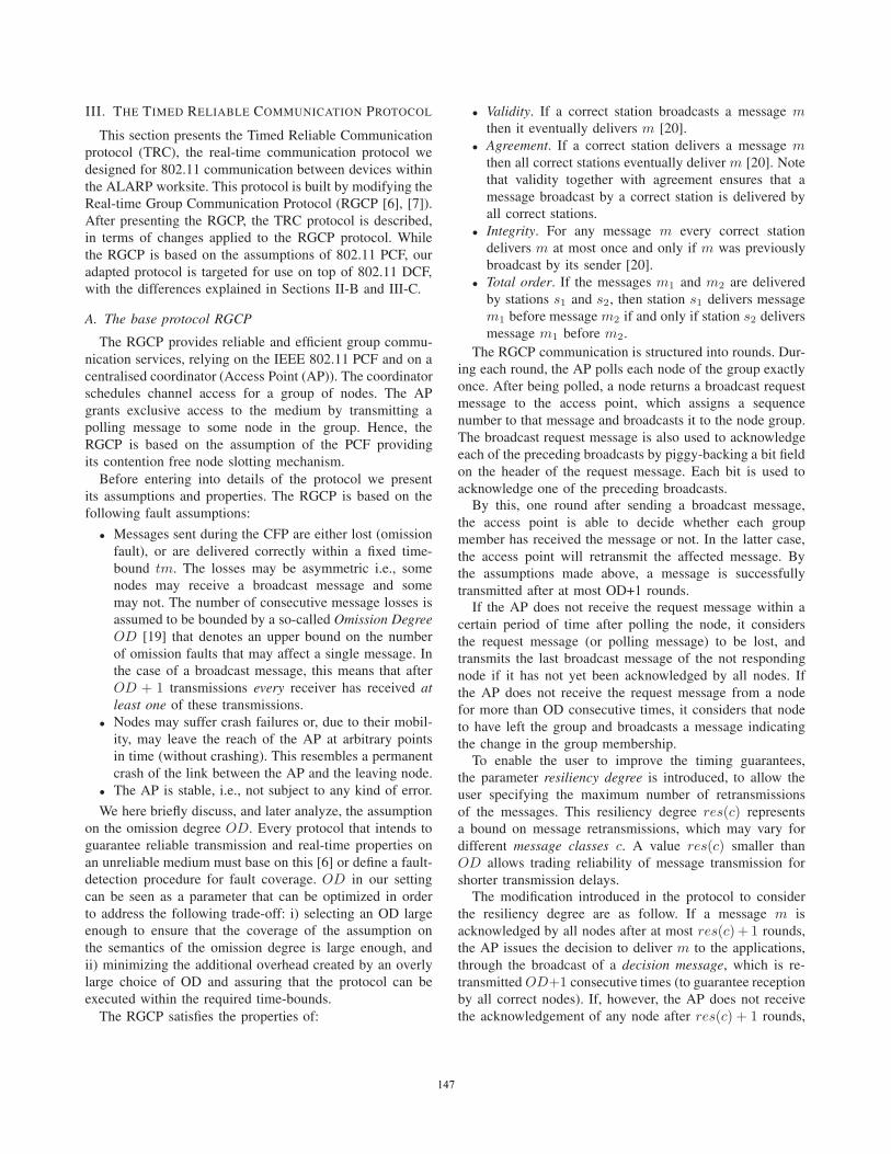
each 200 simulation runs of 12 hours simulated time underthe cross-traffic scenario. The settings with the longest slot-times (and less than 20 nodes), S4 with 30ms, S3 with25ms as well as S5 with 50ms slot duration, completethe workday with 0 and 2 disconnects in all 200 runs,respectively. S2 has 6 disconnects. The scenario S1 with15ms slot durations runs exhibit a high probability ofdisconnect. For each estimator, the 95% confidence interval
153153
0
0.2
0.4
0.6
0.8
1
S1 S2 S3 S4 S5
Extrapolation Settings
Estimated Probability of 12 Hour Runs without Disconnect
Figure 6. Probability to success estimators of the 12 hour runs with 95%confidence intervals, for cross-traffic scenario.
1 2 3 4 5 6 7 8 9 10 110
0.05
0.1
0.15
0.2
0.25
0.3
0.35
Time to Disconnect (Hours)
Dis
conn
ects
Histogram of Disconnects for S1 (200 Runs)
9 runs did not disconnect
1 2 3 4 5 6 7 8 9 10 110
0.05
0.1
0.15
0.2
0.25
0.3
0.35
Time to Disconnect (Hours)
Dis
conn
ects
Histogram of Disconnects for S1 (200 Runs)
9 runs did not disconnect
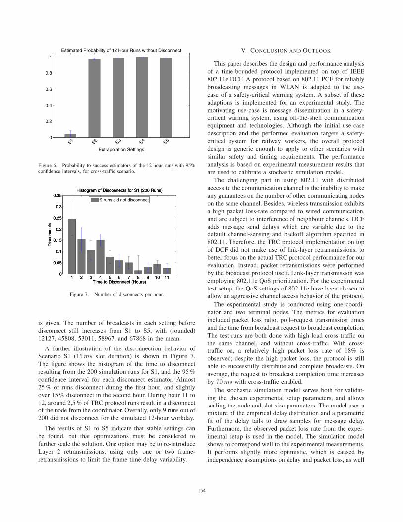
Figure 7. Number of disconnects per hour.
is given. The number of broadcasts in each setting beforedisconnect still increases from S1 to S5, with (rounded)12127, 45808, 53011, 58967, and 67868 in the mean.
A further illustration of the disconnection behavior ofScenario S1 (15ms slot duration) is shown in Figure 7.The figure shows the histogram of the time to disconnectresulting from the 200 simulation runs for S1, and the 95%confidence interval for each disconnect estimator. Almost25% of runs disconnect during the first hour, and slightlyover 15% disconnect in the second hour. During hour 11 to12, around 2,5% of TRC protocol runs result in a disconnectof the node from the coordinator. Overally, only 9 runs out of200 did not disconnect for the simulated 12-hour workday.
The results of S1 to S5 indicate that stable settings canbe found, but that optimizations must be considered tofurther scale the solution. One option may be to re-introduceLayer 2 retransmissions, using only one or two frame-retransmissions to limit the frame time delay variability.
V. CONCLUSION AND OUTLOOK
This paper describes the design and performance analysisof a time-bounded protocol implemented on top of IEEE802.11e DCF. A protocol based on 802.11 PCF for reliablybroadcasting messages in WLAN is adapted to the use-case of a safety-critical warning system. A subset of theseadaptions is implemented for an experimental study. Themotivating use-case is message dissemination in a safety-critical warning system, using off-the-shelf communicationequipment and technologies. Although the initial use-casedescription and the performed evaluation targets a safety-critical system for railway workers, the overall protocoldesign is generic enough to apply to other scenarios withsimilar safety and timing requirements. The performanceanalysis is based on experimental measurement results thatare used to calibrate a stochastic simulation model.
The challenging part in using 802.11 with distributedaccess to the communication channel is the inability to makeany guarantees on the number of other communicating nodeson the same channel. Besides, wireless transmission exhibitsa high packet loss-rate compared to wired communication,and are subject to interference of neighbour channels. DCFadds message send delays which are variable due to thedefault channel-sensing and backoff algorithm specified in802.11. Therefore, the TRC protocol implementation on topof DCF did not make use of link-layer retransmissions, tobetter focus on the actual TRC protocol performance for ourevaluation. Instead, packet retransmissions were performedby the broadcast protocol itself. Link-layer transmission wasemploying 802.11e QoS prioritization. For the experimentaltest setup, the QoS settings of 802.11e have been chosen toallow an aggressive channel access behavior of the protocol.
The experimental study is conducted using one coordi-nator and two terminal nodes. The metrics for evaluationincluded packet loss ratio, poll+request transmission timesand the time from broadcast request to broadcast completion.The test runs are both done with high-load cross-traffic onthe same channel, and without cross-traffic. With cross-traffic on, a relatively high packet loss rate of 18% isobserved; despite the high packet loss, the protocol is stillable to successfully distribute and complete broadcasts. Onaverage, the request to broadcast completion time increasesby 70ms with cross-traffic enabled.The stochastic simulation model serves both for validat-
ing the chosen experimental setup parameters, and allowsscaling the node and slot size parameters. The model uses amixture of the empirical delay distribution and a parametricfit of the delay tails to draw samples for message delay.Furthermore, the observed packet loss rate from the exper-imental setup is used in the model. The simulation modelshows to correspond well to the experimental measurements.It performs slightly more optimistic, which is caused byindependence assumptions on delay and packet loss, as well
154154

as by the irregularities of the node behavior caused by thedriver software in the experimental setup. The simulationmodel is then used to analyze scenarios of extrapolatedsettings with slot sizes from 15 to 50ms, together witha higher number of nodes. The node number is chosenin a way that the application-specific worst-case broadcastcompletion time of 10 seconds is met. The results show thatdisconnections due to failed broadcasts within a workday of12 hours happen very rarely (0 to 2 in 200 runs) in scenariosof 30 to 50ms slot sizes; such a disconnect requires theaffected worker node to move to a safe zone. The timeto disconnect is getting significantly shorter than 12 hoursfor the other scenarios. Therefore, the current realizationcan support at most 12 nodes. Future work will includethe development of analytic models for the disconnectionprobability, such that the analysis of scenarios with verylow disconnection probabilities becomes computationallyfeasible; alternatively, rare event techniques could facilitatean efficient simulation analysis of such settings.
A future detailed study could analyze and compare theprotocol using various IEEE 802.11e settings, also in thepresence of other interfering nodes having QoS featuresenabled. Additionally, the probable positive impact on packettransmission success when allowing one or two link-layerretransmissions should be evaluated.
ACKNOWLEDGMENT
This work has been performed in the framework of theEU FP7 Transport programme (call FP7-SST-2008-RTD-1),Grant no. 234088, which is funded by the European Union.
The Telecommunications Research Center Vienna (FTW)is supported by the Austrian Government and by the Cityof Vienna within the competence center program COMET.
REFERENCES
[1] M. Satyanarayanan, “Pervasive computing: vision and chal-lenges,” Personal Communications, IEEE, vol. 8, no. 4, pp.10 –17, Aug. 2001.
[2] B. Hughes, R. Meier, R. Cunningham, and V. Cahill,“Towards real-time middleware for vehicular ad hocnetworks,” in Proceedings of the 1st ACM internationalworkshop on Vehicular ad hoc networks, ser. VANET ’04.New York, NY, USA: ACM, 2004, pp. 95–96. [Online].Available: http://doi.acm.org/10.1145/1023875.1023894
[3] S. Eichler, “Performance Evaluation of the IEEE 802.11pWAVE Communication Standard,” 2007 IEEE 66th VehicularTechnology Conference, pp. 2199–2203, Sep. 2007.
[4] C. Basile, M. Killijian, and D. Powell, “A Survey of Depend-ability Issues in Mobile Wireless Networks,” LAAS CNRSToulouse, Tech. Rep., 2003.
[5] “ALARP – A railway automatic track warning system basedon distributed personal mobile terminals – FP7-IST-2010-234088 http://www.alarp.eu/.”
[6] M. Mock, E. Nett, and S. Schemmer, “Efficient ReliableReal-Time Group Communication for Wireless Local AreaNetworks,” in EDCC, 1999, pp. 380–400.
[7] E. Nett and S. Schemmer, “Reliable Real-Time Commu-nication in Cooperative Mobile Applications,” IEEE Trans.Computers, vol. 52, no. 2, pp. 166–180, 2003.
[8] A. Lindgren, A. Almquist, and O. Schelen, “Evaluation ofquality of service schemes for IEEE 802.11 wireless LANs,”in Local Computer Networks, 2001. Proceedings. LCN 2001.26th Annual IEEE Conference on, 2001, pp. 348 –351.
[9] J. Sobrinho and A. Krishnakumar, “Quality-of-service in adhoc carrier sense multiple access wireless networks,” SelectedAreas in Communications, IEEE Journal on, vol. 17, no. 8,pp. 1353 –1368, Aug. 1999.
[10] A. Leonovich and H.-W. Ferng, “A time slots coordinationmechanism for IEEE 802.11 WLANs,” Communications Let-ters, IEEE, vol. 14, no. 4, pp. 360 –362, Apr. 2010.
[11] F. Guo and T. Chiueh, “Software TDMA for VoIP Appli-cations Over IEEE 802.11 Wireless LAN,” in INFOCOM2007. 26th IEEE International Conference on ComputerCommunications. IEEE, may 2007, pp. 2366 –2370.
[12] “Office of Rail Regulation, Annual Report on Railway Safety,2005 - http://www.rail-reg.gov.uk/upload/pdf/296.pdf.”
[13] D. Druidi, “Railroad-related work injury fatalities, MonthlyLabor Review, 2007.”
[14] A. Seminatore, L. Ghelardoni, A. Ceccarelli, L. Falai,M. Schultheis, and B. Malinowsky, “ALARP (A RailwayAutomatic Track Warning System Based on Distributed Per-sonal Mobile Terminals),” in submitted to Transport ResearchArena (TRA) - Europe 2012, 2012.
[15] ALARP Consortium, “ALARP, D1.2 – Requirements Speci-fications,” 2010.
[16] G. Bianchi, “Performance analysis of the IEEE 802.11 dis-tributed coordination function,” Selected Areas in Communi-cations, IEEE Journal on, vol. 18, no. 3, pp. 535–547, 2000.
[17] B. Sikdar, “An analytic model for the delay in IEEE 802.11PCF MAC-based wireless networks,” Wireless Communica-tions, IEEE Transactions on, vol. 6, no. 4, pp. 1542–1550,2007.
[18] G. Bianchi, I. Tinnirello, and L. Scalia, “Understanding802.11e contention-based prioritization mechanisms and theircoexistence with legacy 802.11 stations,” Network, IEEE,vol. 19, no. 4, pp. 28–34, 2005.
[19] G. Grünsteidl and H. Kopetz, “A Reliable Multicast Protocolfor Distributed Real-Time Systems,” in Proceedings of the8th IEEE Workshop on Real-Time Operating Systems andSoftware, 1991.
[20] V. Hadzilacos and S. Toueg, “A Modular Approach to Fault-Tolerant Broadcasts and Related Problems,” Ithaca, NY, USA,Tech. Rep., 1994.
[21] “Openwrt–Wireless freedom. Project website: openwrt.org.”
155155