time saver standards interior design
DESCRIPTION
Time Saver Standards Interior DesignTRANSCRIPT


Time-SaverStandards forInterior Design and.
Space PlanningJoseph De Chiara
Julius Panero
Martin Zelnik
McGraw-Hill, Inc.New York
St. Louis
San Francisco
Auckland
BogotaCaracas Hamburg Lisbon London Madrid MexicoMilan
Montreal
New Delhi
Paris
San JuanSao Paulo
Singapore
Sydney
Tokyo
Toronto

Contents
Contributors
vii
Organizations
ix
Foreword
xi
Preface
xiii
1 .
Planning and Design of Interior Spaces 1
Residential SpacesPeriod furniture
P
5Furniture dimensions
44Living rooms
61Dining rooms
80Bedrooms
87Bathrooms
100Kitchens t
149Library/study
190Family/recreation rooms
196Laundry/sewing rooms
200Closets/storage areas
206
Office Spaces
221
General offices and multipleworkstations
223Private offices
231Electronic workstations
241Conference rooms
249Reception areas
260Furniture, furnishings, and equipment
278
Hospitality Spaces
305
Restaurants
307Bars
346Hotels
374
Retail Spaces
385Shops
387Banks
396Department stores
401
Public Restrooms, Toilets, andCoatrooms
423Restrooms and toilets
425Coatrooms
460

2 .
Construction Details and Finishes
467Partitions and wall finishes
469Floors and floor finishes
516Doors
566Ceilings
641Stairs
660Fireplaces
724Lighting
743
3 .
Architectural Woodwork
779Standard joinery and casework details
781Woodwork details
804Cornices and mouldings
866Furniture hardware
887
4 . Specialties
903Plantscaping
906Signage and graphics
931Audio-visual systems
949Auditorium seating
961Security
977Color theory
998Window treatments1015Elevators
1060Indoor recreation
1069Accessories
1075
5 .
General Reference Data
1103Space planning
1106Human factors
1110Floor and wall covering
1122Fabric
1130Electrical
1132Columns, capitals, and entablatures
1135Nails, screws, and bolts
1136Mathematical data and formulas
1139
Credits
1145
Index
1151

ContributorsMarvin AffrimeAndrew Alpern, AIAAmon & Graecen Architects
David Appel, DLF, IALDBertram L . Bassuk Architect
Anthony Beaumont Architect
Jeannie Bochette steelcase
Louis Bowman Architect
Scott Bromley Architect
Bromley Jacobsen
Architecture and Design
Jerry Caldari Architect
Toni Chi/Albert Chen AssociatesWill C h ing
Planning and Design
Barbara Cianci, IALDCameron Clark Architect
Davis, Brody & Wisniewski Architects
Majorie EarthlifeBrad Elias, ASIDDavid Engel
Landscape Architect
Engel/GGP
Landscape Architects
Paul Eshelman, IDECEvans, Moore, Peterson & Woodbridge Architects
Charles D . Flayhan Associates, Inc .Frank J . Forster Architect
Ulrich Franzen Architect
Gensler AssociatesFranklin H . GottschallAdrienne GradJulius Gregory Architect
Albert HalseHochheiser Elias Design Group, Inc .Caleb Hornbolstel Architect
Lees HortonISD IncorporatedLawrence Israel, FAIA ArchitectFrancis Joannes Architect
Ely Jacques Kahn Architect
Mary Jean Kamin, ASIDWilliam H. Kapple, AIAJoseph KleimanDorothy LeeSammy Lee Architect
Lori Lennon, ASID
Howard Litton, ASIDSteve LouieRonald Lubman Architect
Harry Lunstead Design, Inc .Michael Lynn Architect
Michael Lynn & AssociatesNathan Jerry Maltz, AIA Architect
William M. Manley, FASIDMays, Simpson & Hunsicker Architects
Merrill, Humble, and Taylor Architects
Montgomery Winecoff & Associates, Inc .William Morgan, FAIABernhardt E . Muller Architect
Richard J . Neutra Architect
Julius Panero Architect
Panero Zelnik AssociatesParish Hadley Associates, Inc .Perkins & Will Architects
Dennis Piermont, ASLANicholas Politis
Professor, Fashion Institute of Technology
John Russel Pope Architect
William Pulgram Architect
Ramey, Himes & Buchner Architects
Antonin Raymond Architect
Frank RispoliSaarinin, Swanson & Saarinen Architects
Jacqueline SilesThe Space Design GroupRichard StonisWilliam TarrAndrew J . Thomas Architect
Thompson, Robinson, Toraby, Inc .Darius Toraby Architect
Michael Trencher
Professor, Pratt Institute
Verna, Cook, Salomosky Architects
Walker & Gillette Architects
Walker Group/CNILeroy P . Ward Architect
Edgar I . Williams Architect
Charlie WingMartin Zelnik Architect
Simon B . Zelnik, FAIA Architect

Organizations
A & J Washroom AccessoriesAccess AmericaAlvarado Manufacturing Co., Inc.American Olean Tile Company
American Parquet Association
American Sanitary Partition CorporationAmerican Specialties, Inc.American Standard, Inc.Architectural Paneling, Inc.Architectural Woodwork Institute
Armor Elevator Company
AscenteBaumanBrown Manufacturing Co.Buckingham-Virginia Slate Co .
Camden Window and Millwork
Clairson International
Closet Maid SystemsConde Nast Publications, Inc.
Culter Manufacturing Corp.
CurvofliteDesigners Sign Company
Dover Elevator SystemsEggers IndustriesEljer Plumbingware Division of Wallace-Murray Corporation
EuroflairFocal Point, Inc .
Formica Corporation
Franciscan Tile Company
General Electric Lighting
General Services Administration
Glencoe Publishing Co .HabitatHafele
Hartco Flooring/Tibbals Flooring Co .
HawsHerman Miller, Inc.
Hollow Metal Manufacturers AssociationHorton Lees Lighting Designs, Inc .Howe Furniture Company
Hussey Seating Company
Illinois Agricultural Experiment StationIlttala, Inc.Indiana Limestone Institute of America
Insulated Steel Door Systems Institute
Intergraph CorporationInterkal, Inc.JG Furniture Systems, Inc.Just Bulbs Ltd.
Kinney Shoe CorporationKirsch Division of Cooper Industries, Inc.
KohlerLapeyre Stair Co.Lehigh Furniture CorporationLibrary Bureau, Inc.Maclevy Health and Fitness Products
ManvilleMarble Institute of America, Inc.
Marvin WindowsMcGraw-Hill, Inc.McKinney/ParkerMerillatMidwest Plan Service
ModernfoldNational Association of Architectural Metal Manufacturers
National Association of Ornamental Metal Manufacturers
National Cathode Corp.National Retail Merchants Association
National Terrazzo and Mosaic Association, Inc.
Nesson Lamps, Inc .
New York City Housing Authority
Nichols PublishingNiland Company
Osram Corporation
PAM International
Parker/NutonePhilips Lighting Co .Phillips & Brooks, Inc .Pittcon SoftformsPittsburg Corning Corp.

Putnam Rolling Ladder Co., Inc.Railex CorporationRoberts Step-Lite SystemsRoppe Rubber CorporationSt . Charles KitchensSchlage Lock CompanySchulteSelby Furniture Hardware Co., Inc.Simon and SchusterSister Kenny InstituteSteel Door InstituteSteelcaseSweet's Division of McGraw-Hill, Inc.
TarkettTile Council of America, Inc.Triangle Pacific Corp .Western Wood Products AssociationWhirlpoolWhite Consolidated Industries, Inc.Winebarger Church FurnitureWoodwork Institute of CaliforniaUnited States Dept . of AgricultureUnited States Dept. of CommerceUnited States Dept. of Housing and Urban DevelopmentUnited States Dept. of the InteriorUnited States Dept . of Transportation

ForewordA resource of incredible range and detail, this volume was compiled by
three remarkably inspired designers and educators. Because of their
great knowledge of interior design and their sensitivity to the subject
matter, they have created the most comprehensive source book for the
field ever .The editors spent three years bringing this volume to fruition, culling
the best project drawings by outstanding designers to illustrate much
of the subject matter and tapping their own anthropometric expertise
to address space planning and special function areas. They also ad-
dress the importance of historic influence on present-day design with
an impressive review of period furniture and interior details . All of
these things have produced a reference work of such scope and inclu-
siveness that the reader will be relieved of many hours in the pursuit of
details and information, time saved that can be used for more innova-
tion and creativity in developing solutions for client needs.
The authority and abundance of this book are a testimony to the mat-
uration of this profession of ours and to the editors' appreciation and
understanding of its importance .
Jack Lowery, FASID, IDEC
My pleasure in being invited to write part of the Foreword swiftly
changed to respect and, in turn, awe at the scope and depth of this
book .To say that it is an encyclopedic compilation and mass of information
is obvious . But it is especially and uniquely user-friendly . It presents the
written and illustrative data without a trace of pedantry ; it meets a real
need in our interior designer professional resources. The editors' effort,
dedication, and patience, sustained during a period of over three years,
are truly heroic . An astonishing number of hours of input have pro-
duced a reference of incalculable value.I offer the same cautionary advice mentioned in the Preface : If the
book is a wonderfully comprehensive reference and support for interior
design standards, historical material, suggested plan and design crite-
ria, and regulatory limitations, it is not-it will never be-a subsitute for
the inspired, creative design act, for imaginative solutions are always
driven by new cultural conditions, programs, and functional require-
ments.So to all you designers: Continue to spin your dreams, but do not
stray far from this great resource .
Lawrence J. Israel, AIA, FISP

Preface
Time-Saver Standards for Interior Design and Space Planning is a pro-
fessional handbook dealing with the planning, design, and detailing of
interior spaces . Its primary goal is to provide, within a single reference,
information that typically is found dispersed throughout a multitude of
sources, including manufacturers' catalogs, technical literature, books
dealing with historic styles, and documents and drawings from various
projects .This handbook can be used by the small and medium-size interior de-
sign or architectural firm to establish an instant reference library of de-
sign data and details by providing a broad selection of detail types and
techniques . In addition, the large firm will be able to substantially aug-
ment and modify an existing library of details .Perhaps the most unique feature of this handbook is the vast array of
construction and woodwork details reproduced directly from actual
working drawings contributed by some of the nation's leading interior
design and architectural firms . It is this that makes the handbook par-
ticularly useful to the interior designer, architect, and student alike.
This book consists of five sections . The first, entitled Planning and
Design of Interior Spaces, deals with residential, office, hospitality, and
retail spaces in terms of the relevant planning, design, and detailing
data specifically associated with each . The second section, entitled
Construction Details and Finishes, deals with various basic interior con-
struction components associated with most interior spaces . These
components include partitions, wall openings, wall finishes, floors and
floor finishes, doors, ceilings, stairs, fireplaces, and lighting . Details rel-
evant to each component have been contributed by practicing interior
designers and architects as well as manufacturers.The third section, entitled Architectural Woodwork, deals with stan-
dard joinery and casework details, customized woodwork details, cor-
nices and mouldings, and furniture hardware . The fourth section, enti-
tled Specialties, deals with various specialized areas of equipment,
systems, furnishings, and decoration, including signage and graphics,
audio-visual systems, window treatments, and accessories. Informa-
tion for these subject areas is drawn from manufacturers, suppliers,
and designers.The fifth section, entitled General Reference Data, provides the most
comprehensive set of time-saving reference materials found in hand-
books of this type, including tables, charts, formulas, and planning
guidelines . Of particular interest to the architect, interior designer, and
facility manager are tables that can be easily used to determine carpet
and wall covering yardage . Charts and drawings relative to human fac-
tors and planning standards are also provided .It should be noted that since the details and other information pre-

sented in this book have been compiled from so many differentsources, it is difficult to ensure that all the data are entirely accurate orappropriate ; for example, in some instances planning guidelines mayreflect minimum acceptable standards and not necessarily ideal or pre-ferred standards . In other instances the details indicated may havebeen perfectly adequate in the context of the total building design ofwhich they were a part, but they may well require modification to re-flect design conditions and the reader's intended use . It should also benoted that building codes, fire safety regulations, barrier-free stan-dards, and many other laws governing the design and construction ofbuildings vary from state to state . Accordingly, the reader should con-sult all applicable local, state, and federal codes for conformance priorto applying any of the information contained in this book . Moreover,the reader is cautioned that the dimensional information provided inconnection with furniture, equipment, appliances, accessories, etc., hasbeen obtained from manufacturers and technical literature and thusvaries from supplier to supplier and from source to source . Certainitems may have been discontinued, others modified, and still others re-placed . Although every effort has been made to ensure the reasonable-ness of the information, the reader is cautioned to consult the manu-facturer of the item specified for current dimensional data .The reader is also advised that most drawings and other illustrative
material have been enlarged or reduced for reasons of page layout andpage size . The reader is cautioned, therefore, to disregard any scaledesignations and not to scale the drawings in order to determine anyadditional dimensional information .
Finally, as mentioned before, the plans and details contained in thisbook were extracted from complete sets of actual working drawingsprepared by many different contributors . They were selected both be-cause they were representative of typical situations faced by the de-signer of interior spaces and because they were particularly informa-tive . The authors would like to underscore the fact that these plans anddetails, as well as all the other material presented in this book, are in-tended to serve only as a helpful point of departure in connection withthe design process, and not as a substitute for original thinking and cre-ativity.Although every effort has been made to present reasonably accurate
information, the editors and publisher assume no liability or responsi-bility for damage to persons or property alleged to have occurred as adirect or indirect consequence of the use and application of any of thecontents of this book. The reader is advised to view the subject matterprimarily as guidelines for preliminary planning and detailing, and toproperly review, modify, and process it to ensure conformance with lo-cal codes and practices and appropriateness of'applicability .
Joseph De ChiaraJulius PaneroMartin Zelnik

Planning and Design of
Interior Spaces


Residential SpacesPeriod furnitureFurniture dimensions
44Living rooms
61Dining rooms
80Bedrooms
87Bathrooms
100Kitchens
149Library/study
190Family/recreation rooms
196Laundry/sewing rooms
200Closets/storage areas
206


Residential Spaces
PERIOD FURNITURE
17th Century American : Colonial
THE 17th Century immigrants brought to America the building tra .ditions of their - native lands . The Parson Capen house (1683) at
Topsfield, Mass ., for example, closely resembles English houses ofthe same period . But the clapboards are typically American . In thepanels at right are close-up details of the Early Colonial background .
T HIS living room is typical of those in the more elaborate EarlyColonial homes . The crewel-embroidered curtains are blue-green
with touches of red . This is taken up by the upholstery-blue-greendamask for the sofas, red tapestry for the chairs. The Oriental rugand the portrait above the fireplace are both in tones of red, brownand yellow, with red dominant .
An alternative color scheme would have blue and yellow up-holstery (needlework for the chairs, satin for the sofas i . The wallswould be pine-paneled, adorned with silver sconces, the curtains abright cotton print in red . yellow, blue and white .
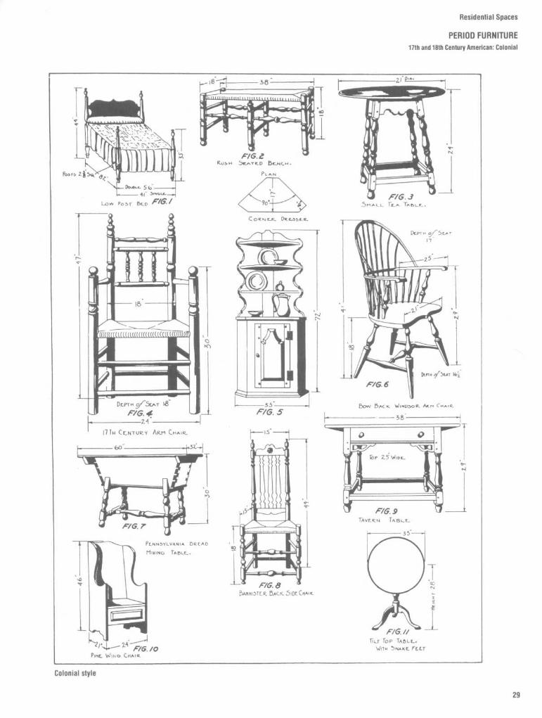
Furniture made in America during the EarlyColonial period (the seventeenth century andthe first quarter of the eighteenth century)was necessarily, and possibly also by choice,of the simplest type . The early colonists,particularly those in New England, had nottime or equipment to spare for any but theessentials of life .
Turning on the lathe was the simplest toachieve and thus the most common form offurniture decoration . It was also a processcapable of infinite variations of design (someare shown in Fig. 1).

tT IE color scheme in this dinin't roiuu i keyed to the low
ones of the pine paneling and walnut furniture, the softgleam of the smooth polished brass chandelier . The bannisterback chairs have rush-bottom seats . Brilliant red and whiteprinted cotton is used for the curtains . The hooked rug is inreds and greens .
Alternatively the curtains might be of red and yellowcrewel embroidery, the upholstery of red brocade . In thepanels at right are furniture and fabrics suited to an EarlyColonial dining room .
Ttits little bedroom with its pine paneling and low ceilingis typical of the Early Colonial period. The bed, deco-
rated with hancin ,,s of crewel work in an Oriental design .i s the most important feature of the room . The chairs areupholstered in yellow damask . The green printed cotton usedfor the little draped window curtains is echoed by the greensin the hooked rug on the floor .
Alternatively the walls might be painted a dark gray-blue, the curtain material being a red printed cotton on agray ground . The furniture is of walnut and oak.
Even the most costly furniture in this EarlyColonial period was usually of solid woodunfinished except for stain or waxing . Ve-neering and shellacking, to gain carefullypatterned graining and high finish, were stillunexploited. The pine paneling on the wallsmight be left unfinished, waxed, or painted.Other woods near at hand in the forests and
so commonly used were oak, birch, maple,and walnut . Generally, American work ispatterned upon English work of 10 or 20years earlier. In Pennsylvania and Delaware,which were settled by colonists of Swedishand German descent (in addition to theEnglish), much of the simple furniture waspainted with its motifs transferred from Euro-
pean peasant art .In the later years of the Early Colonial
period, when New Englanders were alreadybeginning to trade with the Orient, muchChinese porcelain was imported . The Orien-tal influence was strong in textiles ; the Treeof Life pattern was very popular at thisperiod . Native textiles copied the patterns

Residential Spaces
PERIOD FURNITURE
17th Century American : Colonial
and colors of India, Persia, and China. Theoriginals, or good copies of them, wereusually imported from England.The colors in common use were of a piece
with the solid, sturdy furniture . They seldomescaped from the conventional round of blue,red, gold, and natural gray. The only excep-tions were imported fabrics and the occa-
sional hard brilliance of the Chinese porcelainfound in the great houses of the day. What-ever luxury there was at this time expresseditself in textiles and silver rather than infurniture . Settlers in the South, manyof themEnglish aristocrats, maintained a higher stan-dard of comfort than those in the North; theyimported most of their furniture and fabrics
from England and continued to do so for along time .
Early Colonial furniture taken as a whole issturdy, but not subtle . Furniture patterns inthis country changed slowly. Paneling re-lieved the larger flat areas such as cupboarddoors and drawer fronts . The latter werefurther decorated by quite elaborate fretted

Residential Spaces
PERIOD FURNITURE17th Century American : Colonial
xass and wrought-iron hardware (see Fig . 1) .More carefully embellished than the ear-
iest American furniture were the piecesmported by the colonists from their variousiomelands . These pieces, and the memories>f others left behind, later served as modelsor American craftsmen . The dominant in-luence was Dutch, for the English had alollander William of Orange, as king . He andtis queen, Mary, gave their names to a style)f which elaborate stretchers (particularly oniighboys, lowboys, and occasional tables)and scrolled legs are among the most ob-rious characteristics.Also from Dutch, Spanish, and Portuguese
iources are derived most of the carved feet

Residential Spaces
PERIOD FURNITURE
18th Century American : Colonial
THE EXTE111011
The architectural details shownin the five panels at right are char-acteristic of the Ijack,,round for MiltCentury Colonial decoration . As oneof the finest houses of the period ticvhave pictured hat right) `'V'rstovrr -the great rnansLon erected 11y Nk illialn13N'rd in Charles Cite Co ., Virginia ."Topical of this period are the brickwalls and cldrnnrys, the stone orwhite painted brick trine . In the Noriltwood was in more comnwn use thanbrick for the exterior, and the interiorwooden trite was finny detailed .
THE LIVING .1101)111
The furniture, faln- ics and ac-cessorirs shown in fit( ,,,- panels areall suitable to the living room . andthey- are all topical of the 18111 Cen-tury Colonial stole .
Tlte interior pictured at right isa fine Colonial living rooun carefullyrestored to its 18111 Ccnlurv state . 'fleewalls are Naples Yellow, the colwnnsan(] fireplace white . Red and greenare dominant in the Oriental rug,idark greens and browns in the 1),-r .trait above the fireplace . So the sofais uldudsirred in ~iriped satin . the::rlnchair in Nrllow \ vnctian brocade,the wing Chair in a fit intcd linen . Theurns are of Chinese I-rcrlain .
Another col,,t scheme tniglrt lie :pearly gray walls, oyster white col-lunns
and
fireplace .
RI 'd
tioould
hedominant in the Oriental carpet, darkgreens and red in the portrait . Therewould be red damask oo the sofa .green rep on tliv wing , hair, and golddamask for th~ ;mile hair .
Whereas furniture of the Early Colonial
from Europe . The "Pennsylvania fireplace"
Batty Langley, and William Pain, who in turnperiod was often so primitive as to be
or "Franklin stove" was invented by Ben-
were in debt to the Italian masters Palladioreferred to as "kitchen Colonial ;' in this
jamin Franklin in 1742 and immediately be-
and Giacomo Leoni . Among the cabinet-succeeding era dignity and luxury prevail in
came popular up and down the Atlantic
makers were Moses Dodge, Stephenthe centers of taste . The furnishings reflect
seaboard . Philadelphia was a furniture style
Dwight, Henry Hardcastle, Gilbert Ash,the fashionable contemporary styles of Eng-
center, in fact the most active in the creation
Robert Wallace, Charles Shipman, John Brin-land and stately country homes, whether on
of
taste,
with
Boston
and
Charleston
nor, John Tremain, Charles Warham, JohnNew England farms or Virginian and Carolina
following
Brown, Bemsley Wells, Thomas and Ben-plantations, followed these styles . This gave
A number of artists and craftsmen of this
jamin Laskey, Jonathan Goodhue, and Jobrise to a number of notable architects, crafts-
period bear mentioning . Among the archi-
Trask . Among the upholsterers were Ste-men, and workers in metal and wood .
tects were Samuel McIntire, Charles Bul-
phen Callow, Richard Wenman, Joseph Cox,The eighteenth century Colonial period
finch, John James, Richard Mundy Peter
and John Taylor ; among the metalworkerswas
the first of the
really great
eras
in
Harrison, John Kirk, and Isaac Royall . These
were William Coffin, Wilkins, Joseph Liddell,American cabinetmaking .
men were greatly influenced by the English
William Bradford, John Bassett, and PeterThe manufacture of wallpaper in this coin-
architects Isaac Ware, James Gibbs, Robert
Harby ; and among the painters were Johntry was begun by 1763 . Before this it was
Morris, Abraham Swan, William Halfpenny,
Singleton Copley, Joseph Blackburn, John

Residential Spaces
PERIOD FURNITURE18th Century American : Colonial
DINING 1100M
The furniture and fabricsshown in the five panels at rightwould look well in any diningroom ; but for your guidance in theselection of materials and colorswe illustrate at right a fine Colo-nial dining room as it might haveappeared in the 18th Century .
The pine-panelled walls arecolored a light ocher, the nichesChinese red . Curtain ; are Frenchblue . Blue, rust and beige predorn .inate in the Oriental rug, darkgreen, blue and black in the por .trait over the fireplace. Table andchairs are of walnut, the sideboardof mahogany.
An alternative color schemewould lie light blue-gray walls withcream niches . Curtains would beoyster white silk, the Oriental rughaving a greenish tan background .
13LI)ROOM
1n the bedroom at right,choice of color and textures wasdesigned to achieve an impressionof warmth and intimacy . The pan-eled walls are in two tones of g r ay-green, the ceiling ocher . Curtainsare antique gray-green satin .
Furniture is walnut, exceptfor the malnogany bed, which hasa yellow taffeta spread . Firesidechairs arc covered in crimson dam-ask side chairs in turkey work .
An alternative color schemewould he : warns gray walls withoyster white moldings . The ailingwould be cream, the carpet solidtaupe, and the curtains of bluedamask . The bed would have awhite moirc spread and blue vatante . The side chairs would ticupholstered in yellow damask, thewing chair in turkev work .
Ramage, James Peale, and Charles WilsonPeale . Important manufacturers were, ofwallpaper, Jackson of Battersea (England)and, of window and bottle glass, BaronStiegel and Caspar Wistar
Fabrics most commonly used during theColonial period were damask, camblet, In-dian gimp and binding, moreen (woolendrapery cloth), harrateen cloth, block-printed
cotton and linen, cashmere, calico, dimity,durance, stout worsted cloth, turkey work(tufted "pilelike"), paduasoy (strong silk), soy,shalloon, watchet, linsey-woolsey, fustian,silk muslin, chintz, Indian calico, tabby, sar-canet, taffeta, horsehair, camak, bancours,and brocade.Woods most commonly used were oak,
ash, elm, red cedar, mahogany, walnut, ma-
pie, pine, and cherry.The Chippendale style merges at one end
with Queen Anne, at the other with Hep-plewhite, Sheraton, and Duncan Phyfe. TheRococo mounts to its zenith and starts todecline within these years . Walnut has a newrival in mahogany. And American craftsmenproduced pieces of a qualitywhich comparesfavorably with English work .

Marble was imported until after the Revo-lution when domestic marbles began to beused . Marble chimney pieces, window sash,lead roofing, and hardware were all importedfrom London . The size of glass windowpanes gradually increased as the centuryprogressed .An order of small pilasters or columns
supporting the mantel in a chimney piece
was found only in imported work prior to theRevolution . Fireplace openings with neithercornice nor mantel shelf were long common .Ears on the architraves were almost univer-sal, and a pediment (always broken) was verycommon . After 1760 the scroll pediment, orasimilar treatment of the architrave, occurs .
Residential Spaces
PERIOD FURNITURE18th Century American : Colonial

Residential Spaces
PERIOD FURNITURE18th Century American : Colonial

Residential Spaces
PERIOD FURNITURE
18th Century American : Federal
The Federal style is at its most suave andelegant in the furniture of Duncan Phyfe, aScotch cabinetmaker who arrived in NewYork about 1795 . He did not originate a style ;he translated prevailing fashions into finecraftsmanship . Thomas Sheraton, then thecurrent English favorite, and the French Di-rectoire cabinetmakers set the style. Allthese designers were profoundly influencedby a rediscovery of the classic splendors ofGreece and Italy.
Reeding of table, chair, and sofa legs andother framing members gives elegance toFederal furniture . Contrasting color veneer isused to outline the edges of tables and desksand to lend interest to large plain surfaces .
T 'sis a fine Federal interior in it, oziginal condition . The
walls and woodwork are painted pistachio green . The curtainsare of I)eige damask . the sofa upholstered in red and gold damask .(;old damask is used for the armchairs, yellow damask for thevide chairs . The Oriental rug is wine red in tone, the furniture,mahogany . The clock is of ox-blood marble .
An alternate scherne would have light gray-blue walls andwoodwork . The draperies would be yellow damask, the chairs up-holstered in green damask . The furniture and fabrics shown inpanels at right would also be suitable for the Federal living room
s a typical mansion of the Federal period we show MappaTall in Trenton, N.Y . It was started in the closing years of the
18th Century and completed in 1809 . The portico and the simplepediment exemplify the prevailing Classic trend . In the panels to theright are some topical details frimi the Federal period background

Residential Spaces
PERIOD FURNITURE
18th CenturyAmerican : Federal
w1
THE dining room shown above the walls are mist gray, theichimneypiece ochre and white marble . The drapery andupholstery are both cherry silk damask. The Oriental rug isin tones of brown, blue and beige. The furniture is mahogany .
An alternate scheme would include : soft gray-greenwalls, beige silk damask curtains, red damask upholstery .The sconces, clock and picture frames would be gilt.
This original Federal period dining room will give youideas for using the furniture and fabrics shown in the panelsat right . Or reproductions of similar pieces are appropriate .
Tr',ttts bedroom shown above is typical of those found in finej houses during the Federal period . Walls, woodwork andchimneypiece are painted moss green . The upholstery isbeige damask, except for yellow satin on the desk chair. Therug is in two tones of burgundy with a design of green, pinkand white . On the walls are engravings in gilt frames .
An alternate color scheme would have walls and wood-work painted peach color . The rug would then be olive greenwith a design in yellow and pink . The upholstery would beblue, except for red satin on the seat of the desk chair . Otherfurniture and fabrics suitable for this room are shown at right
Another characteristic subtlety is the raisedhairline of wood, known as a cock beading,which is used to finish off the edges ofdrawers. Phyfe used white wood linings forthe drawers in his furniture, instead of thepine linings universally employed by otherAmerican cabinetmakers of this period .
Brass ornaments (probably for the mostpart imported) are used extensively on
Federal pieces . They have brass feet andcasters, ring handles, and other types ofapplied ornament . Toward the end of theperiod, about 1825, china and glass knobsbegan to supplant brass rings as drawerpulls.The new United States was in its first
throes of nationalism ; consequently its em-blem, the eagle, appears everywhere - on
transparencies in windows, painted on fans,inlaid in mirrors, desks, knife boxes, andbrass work . The "Spread Eagle" became afavorite tavern sign . All kinds of historicscenes and patriotic emblems appear asdecoration on clocks .And yet, the Classic influence was even
stronger than the patriotic. Earthenware andporcelain such as Crown-Derby, Worcester,

Residential Spaces
PERIOD FURNITURE
18th Century American: Federal
and Wedgwood were molded in Classicforms and painted with delicate sepia figuresin Classic robes . Silver and Sheffield plate(the latter replacing pewter) also followedClassic forms. Ireland sent Waterford glass.
Fabrics most used were damask, brocade,satin, taffeta, haircloth, toile de Jouy, printedcotton, and silk .Woodsmost used were mahogany, cherry,
and maple ; and fruit woods in less splendidfurniture . Curly maple often replaced thesatinwood used in European models . After1800 rosewood was used for the more costlyfurniture .The Federal motifs derive almost ex-
clusively from classical sources. Theacanthus leaf, the lyre, the saber leg, thelion's mask and paw, the bowknot, rosettes,
thunderbolts, trumpets, and drapery swagsare all to be found on the list of standardFederal furniture motifs .After the War of 1812, when the Federal
era rose to its zenith of popularity, the laurel,cornucopia, and eagle motifs became es-pecially popular. (See Fig . 2.)
Phyfe's treatment of the acanthus leaf is sotypical that many of his pieces depend upon

Residential Spaces
PERIOD FURNITURE
18th Century American : Federal
this for their identification . It is simplified intoa series of rounded grooves and ridges with araised tapering ridge up the center.The lyre was used to fill in the backs of
chairs, to decorate the arms of sofas, and(split apart) to support mirrors on dressingtables . Two crossed lyres are used as supportfor a pedestal table.

YPICAL of the better country houses in the second half of the18th Century, is this design from Abraham Swan's British Arch-
itect, one of the many handbooks of builders' designs, which at thisperiod carried news of architectural fashions from England toAmerica . At right are close-up details of the Georgian background
TH}: pine-paneled walls in this characteristic Georgian livingroom are left unstained. The silk curtains are richly embroidered
in many colors on a yellow ground which echoes the gilt framesused for pictures and mirrors . The crimson upholstery of the mahog-any furniture is given added quality by the olive green carpet .
An alternative color scheme would be to have the walls painteddark gray-green with carving picked out in gold . The wall-to-wallcarpet would be taupe, the upholstery of the wing chairs yellowItalian damask . In both color schemes needlepoint and naturalleather would be used for upholstering other chairs in the room
Chippendale was a dominating factor inthe history of Georgian furniture design andhis name serves as a convenient tag for theperiod centering in the reign of the second ofthe three Georges who provide the periodtitle . Yet this English cabinetmaker achievedeminence not so much by his ownwork as bythat of his copyists .They all used the designs in The Gen-
tleman and Cabinet-Makers' Director, pub-lished by Chippendale in 1754 . To fill this bookChippendale commandeered all the ideas hecould lay his hands on and then embroideredthem with his own fancy, adapted them to hisown forms. He plundered the design man-uals of China and the French rococo, of theancient Gothic masters, and of his immediatepredecessors in the English furniture trade.
Residential Spaces
PERIOD FURNITURE18th Century English : Georgian
From the craftsmen of the early eighteenthcentury Chippendale borrowed such testedforms as the cabriole leg, the claw-and-ballfoot, and the typical acanthus leaf ornament .But to each of them he added a grace and
charm of which the earlier furniture makershad never been capable.Thomas Chippendale was a typical product
of that brilliant English society which flour-ished during the mid-eighteenth century. He

Residential Spaces
PERIOD FURNITURE18th Century Engllsh: Georgian
HERE the walls are pine-paneled, the wood being left itsnatural honey color . The consoles are also of pine .
But brilliant against this pale background are the red damaskcurtains, and the mahogany furniture with its red and yel-low striped silk upholstery.
Alternatively, the walls might be painted light blueas a background for yellow brocade curtains . The mahoganytable and chairs stand on an Oriental rug which repeatscolors found in the needlepoint upholstery . In the panels atright is furniture suitable for a room of this style
C IfARACrERts'rIC of the Georgian period are the richly em-broidered Chinese silk draperies and the delicately
fretted four-poster bed in this room . The dominant tone isyellow, against which is posed green upholstery, with agun-metal carpet for base, putty walls for background .
Alternatively the walls could be pale green, the carpetbrown, the upholstery blue-green and yellow, the ceilingpale apricot. In the panels at right are other pieces suitablofor a room of this type. Modern reproductions of such authen-tic pieces are available in good furniture stores
was a contemporary of Josiah Wedgwood,the potter, and of Edmund Burke, the orator.Boswell and Johnson, Benjamin Franklin,Garrick, Gibbon, and Goldsmith, all addedtheir wit and intelligence to the creation of asturdy culture .Thomas Chippendale served their chang-
ing taste and their fashionable whims. In his
later years he was engaged in making fur-niture of classic, elegant simplicity for thebrothers Adam . His earlier work to his owndesigns, his love of gilt and gaudy color, hisfascination with the exotic - all typical of theage in which he lived - suggest that he mighthave made a brilliant stage designer.
Chippendale is the first personality in the
history of furniture style . This was due less tohis fine craftsmanship than to his ability as apublicist . He was the first cabinetmaker topublish a book of furniture designs . Theinfluence of his Director was particularlystrong in Philadelphia, but the Americancabinetmakers usually simplified his exuber-ant ornament to suit their clients' taste and
Residential Spaces
PERIOD FURNITURE
18th Century English: Georgian
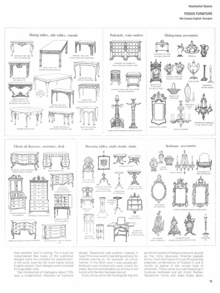
their workers' skill in carving. For it must beremembered that many of the publisheddesigns were too complex for reproductionin the solid, even by the most highly skilledEnglish carvers. Such designs were intendedfor inspiration only.The introduction of mahogany about 1725
was a fundamental influence on furniture
design . Rosewood was another material infavor. Pine was used for paneling and also forintricate carving as, for example, on mirrorframes . In the latter case it was usually gilt .Amboyna was occasionally used, mostly forinlays . But the considerable use of inlay is notfound until the late Georgian period .
From China come the rectangular leg and
an infinite variety of fretted ornament, as wellas the more obviously Oriental pagodaforms. From the France of Louis XV come theelaborate combinations of foliated C and Sscrolls so typical of the rococo style ofornament . These came to a lush flowering infurniture hardware and gilt mirror frames .Serpentine fronts and sides broke down

Residential Spaces
PERIOD FURNITURE181h Century English: Georgian
even the solid rectangular forms of suchtraditionally four-square pieces as chests ofdrawers and tables . (For typical profiles anddecorative motifs see Fig . 3.)Romance was sought in the past as well as
the East ; the pointed Gothic arch and bur-geoning crockets turn up in all kinds offurniture and decoration .

Tae exterior of a later Georgian house, such as the one shownabove, would have been finished in cream-painted stucco with
stone trim . The Classic detail was in carved stone or molded stucco .At right are details of the architectural background at this period .
l~GREev brocade curtains, bound with gold, and green brocade up-
holstery on the sofa and adjacent chairs stand out brilliantlyagainst the French white of these walls . A damask in tones of coffeeand gold is used for the other chairs, a red moire for the other sofa .All these colors are repeated in the rug . The dark brown red ofpolished mahogany appears in the doors and furniture . Some of thesmaller pieces are inlaid with satinwood .
Alternatively the walls might be pale pink with white mold-ings. Upholstery would be blue green except for the chairs by thefire in lemon yellow brocade and the sofa in gold satin .
Chippendale went for inspiration to Chi-nese and Gothic decoration . The great de-signers of the later Georgian period - thebrothers Adam, George Hepplewhite, andThomas Sheraton - were entranced by therecently discovered Classic glories of Pom-peii and Herculaneum, and by the slim pret-tiness in vogue at the French court .The motifs most characteristic of the later
Georgian period (see Fig. 4) are all of Classicorigin : acanthus leaf and honeysuckle, ram'shead, winged griffin and lion, laurel, andgarland.
Characteristic of this period is the perfectcoordination between architects, painters,and furniture designers. The four Adambrothers - John, Robert, James, andWilliam, who trademarked themselves theAdelphi (Greek for brothers) -wereScots by
Residential Spaces
PERIOD FURNITURE18th Century English : Late Georgian
birth, architects by profession . They did notconsider their job at an end when they haddesigned the shell of a house. Every detail offurnishing, decoration, and lighting was es-pecially designed by the Adams to give arounded effect . Nothing was too small or
unimportant to deserve their attention. Thebest craftsmen would then be employed tocarry out their designs. Chippendale andHepplewhite, perhaps Sheraton also, madefurniture for the Adams.
All these designers followed Chippen-

Residential Spaces
PERIOD FURNITURE
18th Century English : Late Georgian
T 11-E pale blur-green walls are relieved by grisaille paint-
ings in delicate Classic taste . Gold appears in the leatherchair seats, in the mirror above the consoles and in thebinding of the white curtains. Green and beige enliven thecarpet and painted ceiling design .
Alternatively the wall paintings might be brighter andmore varied in color, including Naples yellow, inauve andgreen . Curtains and chair seats would be cherry, the ceilingpainting cinnamon brown and white .
PALE colors are dominant here. The sofa, painted oysterwhite, is upholstered in apple green satin . The rnaliogany
lied is covered in white taffeta trimmed with apple green .and the armchair upholstery is cinnamon and gold-stripeddamask . Curtains are white silk, gold-trimmed .
Alternatively the color scheme might he hased on goldand white with blue green silk on the bed and yellow satinupholstery on the armchair for contrast. In the panels tothe right are a number of authentic pieces which might It( ,used in a Georgian bcdroonn such as this .
dale's lead by publishing design handbooksfor the use of other less experienced and lessimaginative craftsmen in this country and inthe English provinces outside London . Hereis seen the changing fashion: lowboys arebeing supplanted by dressing tables, high-boys by wardrobes. Color and inlay becomemore popular than carving, with Sheraton asthe champion of inlay against painting .
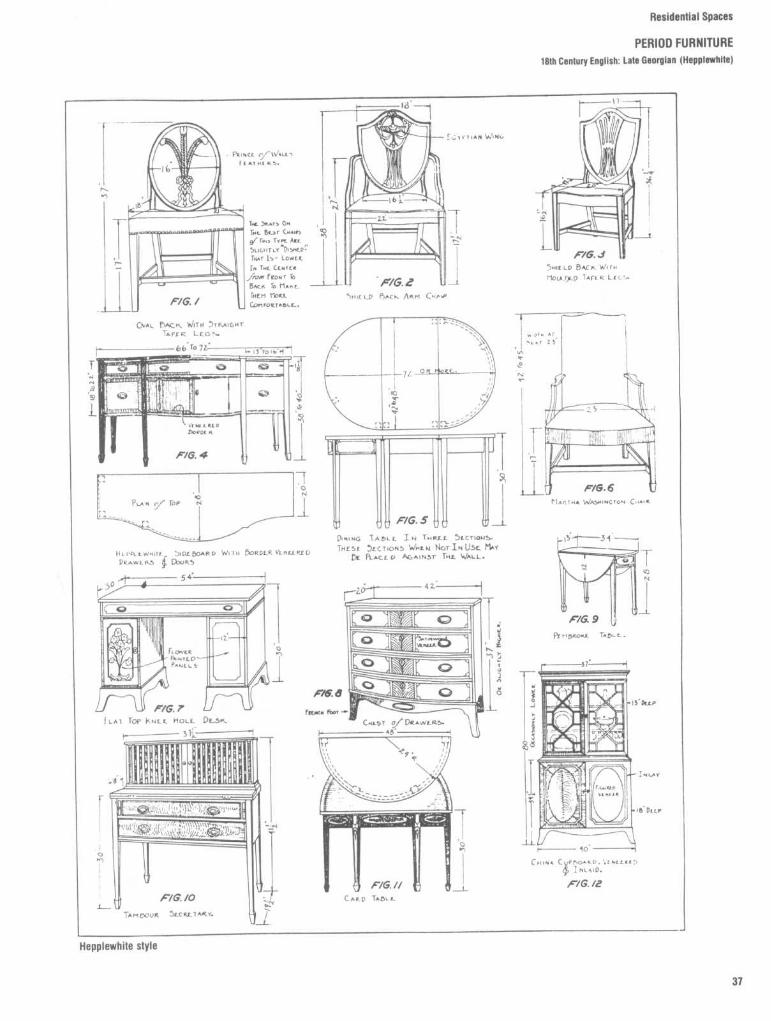
Hepplewhite's work is usually charac-terized by his affection for curves, Sheraton'sby a preference for straight lines . This wasprobably because Hepplewhite was morestrongly influenced than Sheraton by con-temporary French work, which wasenlivened by a profusion of delicate curves .Of particular interest in Sheraton's work arehis designs for ingenious folding and multi-
purpose furniture such as folding beds, com-bined bookcases and washstand, andcouches that folded up to become tables .These were designed for use in those bed-rooms which were now doubling as parlorsduring the day.
This later Georgian period has often beenlabeled the Age of Satinwood. All the design-ers eagerly exploited the possibilities of ve-

Residential Spaces
PERIOD FURNITURE
18th Century English: Late Georgian
neering and inlay with woods such as satin-wood and amboyna, ebony, sycamore, holly,kingwood, and lime . Ivory and brass inlaywere often used to mark key plates .Some of these motifs (the acanthus leaf,
for example) had been in use by Englishdesigners for more than half a century. Butnow, reintroduced from Italy by means ofmeasured drawings, they take on a fresh
elegance . Italian painters were brought in -Pergolesi, Zucchi, and Cipriani - to providethe background of decoration . Angelica Kauf-mann, a Swiss, filled their wreathed panelswith neo-Classic figures .
Yet the solid tradition of English crafts-manship remained intact beneath all thesechanging fashions . The basic proportionsremain almost inviolate . Hepplewhite at-
tempted (in his own words) "to unite ele-gance with utility, and to blend the usefulwith the agreeable"

Residential Spaces
PERIOD FURNITURE18th Century English : Late Georgian

tte typical Directoire chateau shows French Renaissance tradi-tion crossed with the newer Classic vogue . The center panel of
this facade is of stone, the remainder in two shades of paintedstucco, perhaps in such gay colors as salmon, tan and blue .
CHARACTERISTICALLY pale range of colors keeps this room inperiod . The walls are a pinkish gray, the doors gray and gold .
The curtains are oyster white bound in gray and the rug predomi-nantly white except for green and gold in the center . Green recursin the upholstery of the armchair, side chairs and sofa, and gold(satin) in the sofa and meridienne by the fireplace .
For added color the fireside pieces might be upholstered inred satin, the other furniture in gold and blue striped satin . Inpanels at right are other pieces suitable for such a room .
The Directoire was France's recovery pe-riod after the shock of a six-year revolution .The Directoire, established in 1795, lastedonly a brief four years; but this was longenough for the designers to sketch in theoutlines of a new style . Those outlines wereto be filled in later as Directoire merged intoEmpire ; these are but two stages in a singlestyle .With the rise of Napoleon to absolute
power, the delicate style of the Directoirewas taken over and developed "for tha goodof the State." It was to be made into a Frenchnational style thoroughly imbued with thepolitical principles which were to guide thenew state .
Imperial Rome was found to provide thedignity and impressiveness required in the
Residential Spaces
PERIOD FURNITURELate 18th-Early 19th Century French : Dlrectolre and Empire
prototype, so all the Imperial symbols wereconverted to use . The symmetrical shapes ofheavy proportion were taken over un-changed, copied in wood instead of beingreproduced in stone or bronze .Most pieces displayed large surfaces of
highly polished wood, usually mahogany.They were not, as a rule, decorated bymolding or paneling, or even by carving.Ornamentation wasalmost always applied orinlaid . Most typically it took the form of gildedbas reliefs tacked to the smooth wood sur-

Residential Spaces
PERIOD FURNITURELate 18th-Early 19th Century French : Directoire and Empire
Ttte rich brown of polished mahogany in this table issurrounded by chairs painted gold and white, uphol-
stered in blue satin . The walls are painted oyster whilepicked out with yellow moldings . Above the doors art! whiteClassic figure paintings with a lilue background which isechoed in the blue taffeta curtains .
Alternatively the walls might be painted green withthe cornice picked out in white and gold . The chairs wouldthen be upholstered in red . Other pieces suitable for a roomof this type are shown in the panels at right .
PINK wAI.ts decorated in white and gold provide a goodbackground for this tnalu)gany and rosewood furniture
relieved with brass mounts . Fabrics are gayly colored here :blue taffeta for curtains and bell canopy, striped yellowand red satin for the chairs, and yellow satin for the twostools (which have white-painted frames) .
An alternative color sclx-me would have dark beigewalls, green taffeta for the curtains and bed canopy . Mostof the furniture would be painted white and gold . At rightare Other pieces and fabrics suitable for this type of room .
faces . Painted decoration was more com-monly used on walls and ceilings than forfurniture .The general color scheme is rich, dark, and
somewhat heavy. Rich deep mahogany,French polished and often stained red, wasthe favorite material . Rosewood and ebonywere also in favor. Where other woods wereused, their nature was concealed by stainingto imitate the more popular species .
Round tables were popular. They usuallystood on a pedestal or tripod vase . The topwas commonly of porphyry or marble . Bedsdeveloped into Classic ceremonial coucheswith scrolled ends . The popular craze for allthings Roman extended to include women'sdresses and Lucullan banquets .
In the early (Directoire) part of the periodfabrics were quite delicately colored, thedecorative motifs still possessed some Gre-
cian delicacy of form, and much of thefurniture was painted and gilt . Later, underNapoleon's fist, fabrics were usually in deepprimary colors, the motifs of Imperial Romanheaviness, the furniture of dark red polishedmahogany.From each of his campaigns he brought
home some new decorative motif which hewould turn over to his craftsmen for use inthe net batch of furniture made to his order
Residential Spaces
PERIOD FURNITURELate 18th.-Early 19th Century French : Directoire and Empire
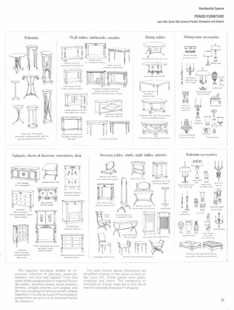
The Egyptian campaign yielded an im-pressive collection of sphinxes, pyramids,obelisks, and lotus leaf capitals . From Italycame all the paraphernalia of Imperial Romandecoration, acanthus leaves, laurel wreaths,torches, winged victories, cornucopias, andthe rest, including the famous wreath of beesNapoleon is usually accused of having appro-priated from the arms of an old Italian family,the Barberini.
The early Empire pieces IDirectoire) aresimplified versions of the styles current un-der Louis XVI. These pieces have grace,simplicity, and charm . The hampering re-strictions on foreign trade led to the use ofnative fruitwoods instead of mahogany.

Residential Spaces
PERIOD FURNITURELate 18th-Early 19th Century French : Direcloire and Empire
Residential Spaces
PERIOD FURNITURE17th and 18th Century American : Colonial

Hesidential Spaces
PERIOD FURNITURE17th and 18th Century American: Colonial

Residential Spaces
PERIOD FURNITURE
Late 1811-Early 19th Century American : Federal (Duncan Phyfe)

Residential Spaces
PERIOD FURNITURE
16th Century English : Early Jacobean

Residential Spaces
PERIOD FURNITURE17th Century English: Jacobean

Residential Spaces
PERIOD FURNITURE17th Century English : William & Mary

Residential Spaces
PERIOD FURNITURE18th Century English : Queen Anne

Residential Spaces
PERIOD FURNITUREleth Century English : Georgian (Chippendale)
Residential Spaces
PERIOD FURNITURE18th Century English : Late Georgian (Heppiewhite)

Residential Spaces
PERIOD FURNITURE
18th Century English : Late Georgian (Sheraton)

Residential Spaces
PERIOD FURNITURE
18th Century English : Late Georgian (Brothers Adam)

Residential Spaces
PERIOD FURNITURE18th Century English : Late Georgian (Brothers Adam)
ALL THt fURN1ruR£ Di51oNjvqBY THE BROTHtRs ADAM WAaDVIIT DY GIIICRS. HGPPLEWHITf-CHIPPENDAIC 4 0THER5 .11ficLrrroTHt Comm5slow5. MOST fTHZ.}cMAKERS WITH 1HE Ib5,NeAr-fXCEPTIoN0/CH1Pr'ENDAI-A WFRf.INFLU£NCEoBY THE WORK
THESL AF(TI,>T5,
WHILF_ TI+c FURNITURE- 13 VERYFORnnL- IH CHAKACTF R IT 15Also VERY BLAVTIFVL. ~ TASTLFU1` .No DYTAIL WA5 Too 5MAI.1-T0 W-CL1VL IHEIK ATTrMTION. B251DESTHE ORDINARY PILCI;5 THEY OESIONtpL*HTINO FIXTUREZ . UPHoL5TERY. ,NunLRov5 ACCLSSORIL5.
THE DROTFIERS ADAM WLRE ARCHITECTS ~ rHL FV0.NITURCTHEY DESIGNED WAS INTENDS) -FOR DEFINITt PLACES IN THE-HousES THEY BUILT.
Fop, TH15 Re-A5cN 5omE f THE PLFLCS WER1-LARGE A5 IS THE CASE of R(CC5
!)L--H AS THE TABLE ~PIIRRORSHowm ACovC . ~-Onc DOORCl5t5 W[KE MADE GUITE LONG . rHltPRovop,Tnoms HowrvLR JEtm In Mo5r CA5r-5 To HAVE DEEH .fXCGILWT.IT WAS ON" DACAUS4 ofA DfNRC To HAVE. LVEAY DETAIL. P(ILFr4TIN THE Hou5E5TH£Y Du11,T THAT THEY D[SIGNEO THE FURNITURE,EY'WHICH THEY ARG FAMov5 TOoAY .

Residential Spaces
PERIOD FURNITURE17th and18th Century French: Louis XIV, XV, and XVI
TIHC fAmc5 L15[o ', o LPa5T-
cK LOUL5 XVV Fl .Rj1ITURL WERE_TAPL51WS . DAPJA5K5. fCTHf(5CEA ~,5ATINS. i H TAPF5TRIC5RCTORAL~FJCH (OLCRLDr"M5
\kkJV-U5VAl, LOV,5XV PIECE5WERP UPHCL.STERr_D WI T M THL
SAM[YTATERIAL5 ASC)IVCH
Aaavr-. Wo"TiYE MTIF5DIFFER0 5"NEWHAT. THE I'ICIORAL
F1,tnEn1 G ;.vE "'AV To Tnf-HIGHLY PECORAIIVE . 5HE-U-f.
LEAF MOTIF5. IN LOU5 XVIPIECC~, THE FABRIC5 WERG
DECORATED WoH FCRITAL FL~e
bovaUET5 . RIDDCH :i .GAIC1AHDS
GfVAIHTT FLLWERS. CUPIDS'
FTc. °,1O'FT COLCR5 FR?,gC?11KATE
IM TH ,5 51rtE"

Residential Spaces
PERIOD FURNITURE16th and 17th Century Spanish

Residential Spaces
PERIOD FURNITUREPeriod Styles and Finishes
TABLE 1
Period Style and Finishes
Periodstyle
Early EnglishTudorJacobeanCharles II
Anglo-DutchWilliam& MaryQueen Anne
Early GeorgianChippendale
Late GeorgianAdamHepplewhiteSheratonEmpireFederal
Associated stylesItalian RenaissanceSpanish RenaissanceWilliam & MaryLarger pieces ofQueen Anne
ChippendaleEarly GeorgianLouis XVISmaller pieces ofJacobean, such as gate-legtable or Windsor chairChippendaleEarly GeorgianLouis XVISmaller pieces ofJacobean, such as gate-legtable or Windsor chair
ChineseChippendaleLouis XVIDuncan PhyfeDirectoire
Louis XIV, XV, and XVI All late Georgian styles1 or 2 pieces of Directoire
Spanish Renaissance
Early Colonial
Early American
Modern
French Provincial
Victorian
Italian RenaissanceEarly EnglishLouis XIVAll Early English stylesWilliam & MaryQueen Anne wing chair
Late GeorgianChippendaleQueen AnneDuncan PhyfeFrench ProvincialSwedish ModernChinese Chippendale
18th-centuryAmericanColonialFederalColonialWilliam & MaryQueen Anne
Walls andceilings
Oak panelsRough plaster with oak trimParquetry ceilings
PaperedPainted (in light tones)Hung with fabricsPaneled
Painted dadoPaintedPaneledPapered upper section
Plain plasterPaintedPaperedLarge wood panels paintedGesso ceilings
Rough plaster paintedCeilings same or beamed
Oak panelsRough plaster with oakParquetry ceilingsSmooth plaster, light trimWallpaper, scenic andChinese designsPanelingCeiling plaster
Painted solid colors,striped, figuredPlain papersCombinations of aboveSmooth plasterWallpaper in scenic orgeometric designs
Large-patterned paper
FloorsHardwood stained, darkstrips and planks onflooringStoneTilesHardwood flooringParquetry
Hardwood flooringParquetry
Hardwood flooringParquetry
Large wood panels painted
Hardwood flooringand decorated
ParquetryWallpaper in Chinesemotifs
Hardwood flooringTilesVinyls in tile pattern
Hardwood flooring orplanksVinyls in jaspe patternDark hardwood flooringVinyls in plain or jaspepatterns
Hardwood flooringParquetryVinyls in modern pattern
Hardwood flooringParquetry
Hardwood flooring
Floorcoverings
Oriental and large-patterned domestic rugsPlain rugs
Oriental and large-patterned domestic rugsPlain rugs
Plain or small-patternedrugs or carpetsOriental rugs
Plain or small-patternedrugs or carpetsOriental rugs
Plain or small-patternedrugs or carpetsOriental rugs
Spanish or Oriental rugs
Braided or hooked rugs
Hooked, braided, Oriental,or domestic rugsCarpet, plain, two-tonedpatterned
CarpetRugs in solid colors,geometric patterns
AubussonsHomespun carpet, small-patternedOriental rugs
Carpet in large patternsOriental rugs

Residential Spaces
FURNITURE DIMENSIONSChildren's Furniture and Tables

Residential Spaces
FURNITURE DIMENSIONSSofas, Loveseals, Lounge Chairs, and Arm Chairs

Residential Spaces
FURNITURE DIMENSIONS
Bed/Mattress Types and Sizes
Figure 1 provides the designer with anarray of typical bed and mattress sizes withwhich rooms can be planned. Tables 1 and 2,however, suggest that within the beddingand mattress industries there exists a widerange of sizes from which to select . Manymanufacturers use bed/mattress termi-nology that reflects different dimensionalstandards than that of other manufacturers.Ultimately, the designer, in consultation withthe client, must verify exact measurements .Be sure to take your clients to see and testthe bed or mattress selected . After all, theyare the ones who will have to sleep on it .
TABLE 1
Juvenile, Youth, and Adult Mattress Types and Sizes
Mattress type
BassinetPortable cribJunior cribYouth bedBunk bedDorm bedHospital bedNarrow twinTwin bedFull-size ordouble bedQueen-size bedKing-size bedExtra-long doubleSuper twin
TABLE 2
Pillow Types and Sizes
Pillow type
StandardQueenKing
Width ( in)
Min Max
172224333032363639
5460765445
181920
Width (in)
23 36 4026 45 5232'/2 46 5836 66 7633 75 7636 75 8036 75 8036 74 7539 75 80,84
5460785445
Min Max202122
Length (in)
Min Max
7480808075
Length (in)
7584848080
Min Max
262935
273036
Note : Many manufacturers also make and sell undersized pillows forcribs and youth beds as well as oversized pillows for the larger beds .

Residential Spaces
FURNITURE DIMENSIONSWaterbeds, Sofa Beds/Convertible Sofas, and Wall Beds
Residential Spaces
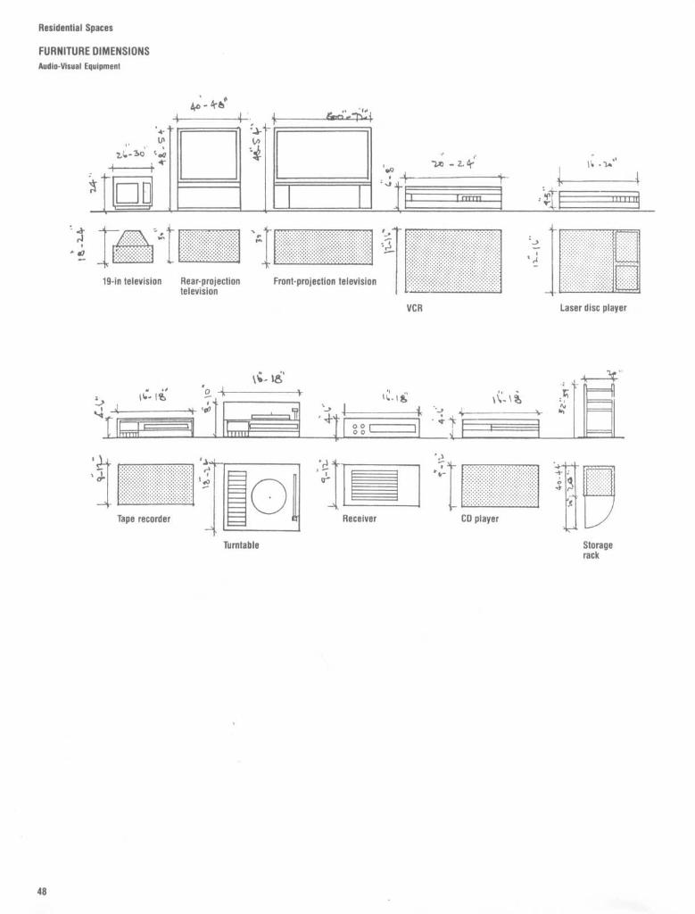
FURNITURE DIMENSIONS
Audio-Visual Equipment

The shape of the viewing area is approx-imately as shown in Fig . 2. Its size is alwaysbased on the size of the image to be viewed .The human eye comprehends detail onlywithin a limited cone angle (about 21/2 min-utes of arc), and the length of chord subtend-ing this arc, i .e ., the image of width, varieswith its distance from the observer. Thus anobject 20 feet away and 6 feet long appearsthe same as a similar object 10 feet away and3 feet long . The size of the viewing area isdetermined by three dimensions :m the minimum distance (1), which is the
distance from the nearest part of the imageto the eye of the closest viewer0 the maximum distance (2), which is the
distance from the furthermost part of theimage to the most distant viewerm the maximum viewing angle (3), which is
the angle between the projection axis andthe line of sight of a person located as farfrom this axis as can be and still see all imagedetail in proper brilliance
Practical minimum and maximum dis-tances are both expressed as multiples of theimage width (W). They vary both with themedium being used and with the type andquality of material being projected, and maybe affected also, in some degree, by personalpreferences. They have not yet been pre-cisely determined by scientific methods, andit's doubtful that such data would have muchpractical value anyway. The generally ac-cepted values, resulting from numerousstudies, are these :
Residential Spaces
FURNITURE DIMENSIONSTelevision Viewing Areas

Residential Spaces
FURNITURE DIMENSIONS

Residential Spaces
FURNITURE DIMENSIONS
20th Century Classic Chairs
WASSILY CHAIR
DESIGNER :Marcel Breuer
YEAR : 1925
MANUFACTURER :Knoll International
DIMENSIONS :30 3/4"W x 29"D x 28'/2"H
MR . CHAIR
DESIGNER :Mies Van Der Rohe
YEAR : 1927
MANUFACTURER :Stendig
DIMENSIONS :21 3/4"W x 32'/4"D x 32'/4"H
LC1 SLING CHAIR
DESIGNER .
Le Corbusier
YEAR : 1928
MANUFACTURER :
Atelier International
DIMENSIONS :
23 5/8"W x 255/8"D x 25/4"H
LC9 LOUNGE CHAIR
DESIGNER :Le Corbusier
YEAR :1928
MANUFACTURER :Atelier International
DIMENSIONS :22"W x 63"D
INGRAM HIGH CHAIR
DESIGNER :Charles R . Macintosh
YEAR : 1900
MANUFACTURER :Atelier International
DIMENSIONS :18'h'1N x 17'h"D x 591/4"H
KUBUS CHAIR
DESIGNER :Joseph Hoffman
YEAR : 1910
DIMENSIONS :36"W x 30'/2"D x 28'/2"H
HAU KOLLER CHAIR
DESIGNER :Joseph Hoffman
YEAR : 1911
DIMENSIONS :35'/2"W x 32"D x 37"H
MIDWAY CHAIR
DESIGNER :Frank Lloyd Wright
YEAR : 1914
MANUFACTURER :Atelier International
DIMENSIONS :16"W x 13"D x 35"H

Residential Spaces
FURNITURE DIMENSIONS
20th Century Classic Chairs
BARCELONA STOOL
DESIGNER :Mies Van Der Rohe
YEAR : 1929
MANUFACTURER :Knoll International
DIMENSIONS :23"W x 22"D x 141/2"H
CHAISE LOUNGE
DESIGNER :Mies Van Der Rohe
YEAR : 1931
MANUFACTURER :Knoll International
DIMENSIONS :23 5/8"W x 471/2"D x 37 1/z"H
ZIG-ZAG CHAIR
DESIGNER :Gerrit Rietveld
YEAR : 1934
MANUFACTURER :Atelier InternationalDIMENSIONS :141/2"W x 17"D x 29"H
PAIMO CHAIR
DESIGNER :Alvar AaIto
YEAR : 1935
MANUFACTURER :Palazetti
DIMENSIONS :231/2"W x 31 1/2"D x 25"H
CESCA ARMCHAIR
DESIGNER :Marcel Breuer
YEAR :1928
MANUFACTURER :Knoll International
DIMENSIONS :225/8"W x 21 5/8"D x 31 3/4"H
BRNO ARMCHAIRDESIGNER :Mies Van Der RoheYEAR :1929
MANUFACTURER :Stendig
DIMENSIONS :18"W x 23"D x 31 1/2"H
LC2 ARMCHAIR
DESIGNER :Le Corbusier
YEAR : 1929
MANUFACTURER :Atelier InternationalDIMENSIONS :30"W x 271/2"D x 261/2"H
BARCELONA CHAIR
DESIGNER :Mies Van Der Rohe
YEAR : 1929MANUFACTURER :Knoll International
DIMENSIONS :30"W x 30"D x 30"H

Residential Spaces
FURNITURE DIMENSIONS20th Century Classic Chairs
MOLDED FIBERGLAS CHAIRDESIGNER :Charles EamesYEAR :1949MANUFACTURER :Herman MillerDIMENSIONS :25"W x 25'/2"D x 31"H
DIAMOND CHAIRDESIGNERHarry BertoiaYEAR : 1952MANUFACTURER :Knoll InternationalDIMENSIONS :33 3/4"W x 28"D x 30'/2"H
LOUNGE CHAIRDESIGNER :Charles EamesYEAR:1956MANUFACTURER.Herman MillerDIMENSIONS :3214,"W x 32j/4"D x 33'/2"H
OTTOMANDESIGNER :Charles EamesYEAR 1956MANUFACTURER.Herman MillerDIMENSIONS :26'1N x 21"D x 15"H
BARREL CHAIRDESIGNER :Frank Lloyd WrightYEAR : 1937MANUFACTURER :Atelier InternationalDIMENSIONS :21 1/2"W x 22"D x 32"H
BUTTERFLY CHAIRDESIGNER :Harday Boner & KurchanYEAR : 1938DIMENSIONS :28"W x 27'/2"D x 35'h"H
MOLDED PLYWOOD CHAIRDESIGNER :Charles EamesYEAR : 1946MANUFACTURER :Herman MillerDIMENSIONS :21'h"W x 19 1/4"D x 29 3/8"H
WOMB CHAIRDESIGNER :Eero SaarinenYEAR :1948MANUFACTURER :Knoll InternationalDIMENSIONS :40"W x 39"D x 35 1/2"H
Residential Spaces
FURNITURE DIMENSIONS
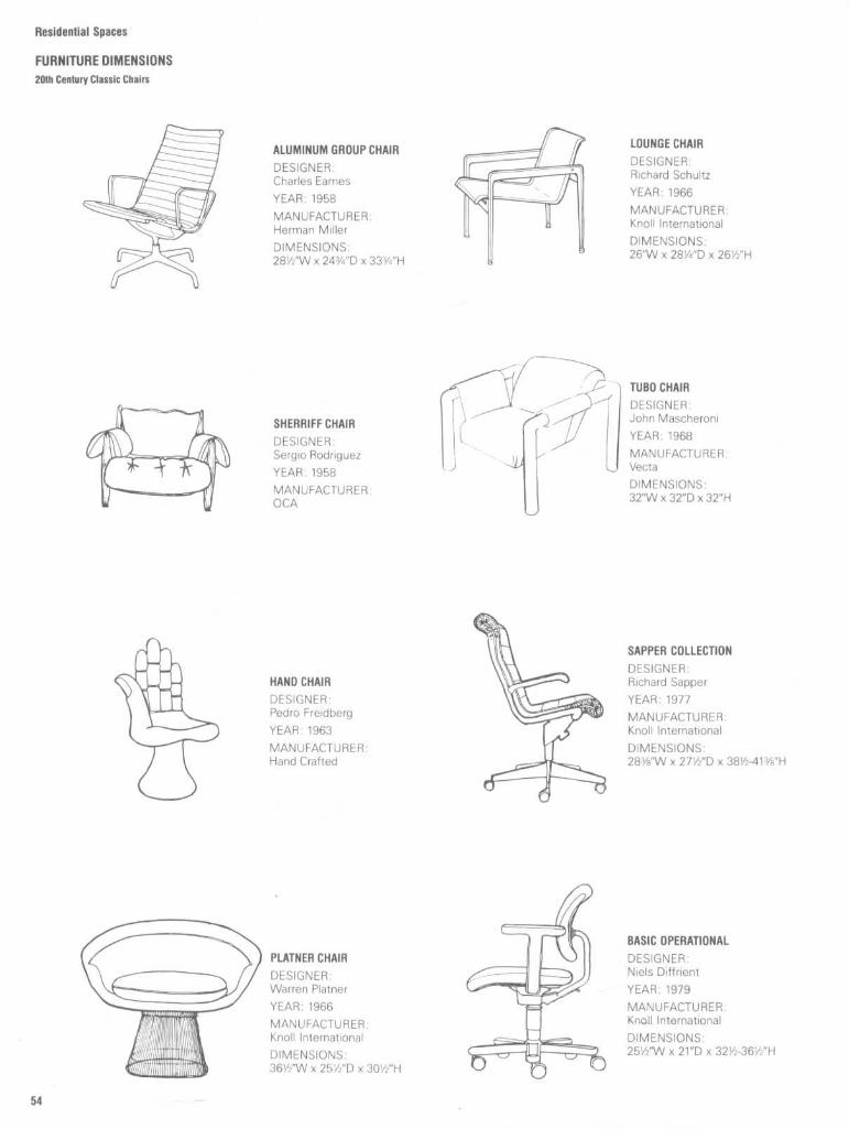
20th Century Classic Chairs
LOUNGE CHAIR
DESIGNER :Richard Schultz
YEAR : 1966
MANUFACTURER :Knoll International
DIMENSIONS :26"W x 28'/4"D x 26'h"H
TUBO CHAIR
DESIGNER :John Mascheroni
YEAR : 1968
MANUFACTURER :Vecta
DIMENSIONS :32"W x 32"D x 32"H
SAPPER COLLECTION
DESIGNER :Richard Sapper
YEAR : 1977MANUFACTURER :Knoll International
DIMENSIONS :283/8"W x 27'/2"D x 38'/2-4V
BASIC OPERATIONAL
DESIGNER :Niels Diffrient
YEAR : 1979
MANUFACTURER :Knoll International
DIMENSIONS :25'/2"W x 21"D x 32'/2-36'h"
ALUMINUM GROUP CHAIR
DESIGNERCharles Eames
YEAR : 1958
MANUFACTURER :Herman Miller
DIMENSIONS :28'/2"W x 24 3/4"D x 33 3/4"H
SHERRIFF CHAIR
DESIGNER :Sergio Rodriguez
YEAR :1958
MANUFACTURER :OCA
HAND CHAIR
DESIGNER :Pedro Freidberg
YEAR : 1963
MANUFACTURER :Hand Crafted
PLATNER CHAIR
DESIGNERWarren Platner
YEAR : 1966
MANUFACTURER :Knoll International
DIMENSIONS :36'/2"W x 251/2"D x 30'h"H

Residential Spaces
FURNITURE DIMENSIONS
20th Century Classic Chairs
NOTHING CONTINUES TOHAPPEN CHAIR
DESIGNERHorward Meisper
YEAR : 1981
MANUFACTURER :Art et Industrie
DIMENSIONS :17"W x 16"D x 37"H
LOUNGE CHAIR
DESIGNER :Michael Graves
YEAR : 1982
MANUFACTURER :Sunar/Hauserman
DIMENSIONS :32"W x 29"D x 29"H
OUEENE ANNE CHAIR
DESIGNER :Robert Venturi
YEAR .1984
MANUFACTURER :Knoll International
DIMENSIONS :26'/2"W x 23'/2"D x 38'/2"H
JEFFERSON CHAIR
DESIGNER :Neils Diffrient
YEAR : 1986
MANUFACTURER.Sunar/Hauserman
DIMENSIONS :32 3/8"W x 34"D x 43'/2"H
OTTOMAN
DESIGNER :Niels Diffrient
YEAR : 1986
MANUFACTURER :Sunar/Hauserman
DIMENSIONS :25'1N x 24"D x 17'/s"H
ED ARCHER CHAIR
DESIGNER.Philippe Starck
YEAR : 1987
MANUFACTURER :Driade Italy
DIMENSIONS :18 1/2"W x 21 1/2"D x 38 1/2"H
STONE CHAIR
DESIGNER :James Kutasi
YEAR :1988
MANUFACTURER :James Kutasi Australia
DIMENSIONS :195/F"W x 195/8"D x 35 1/2"H

Residential Spaces
FURNITURE DIMENSIONSTraditional Bedroom and Dining Room Furniture
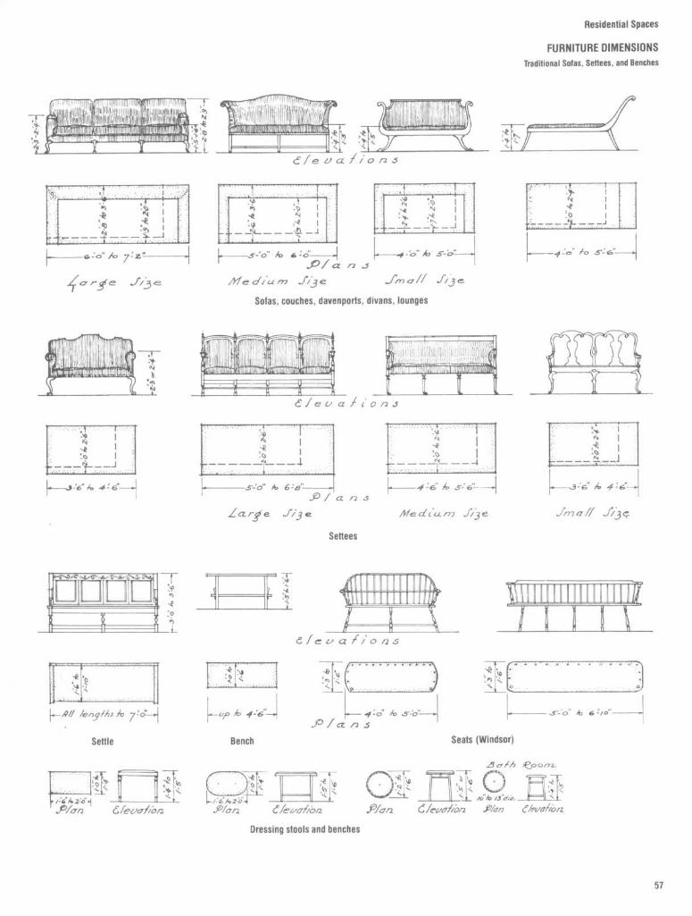
Residential Spaces
FURNITURE DIMENSIONS
Traditional solos, settees, and Benches

Residential Spaces
FURNITURE DIMENSIONS
Traditional Desks, Bookcases, and Chests

Residential Spaces
FURNITURE DIMENSIONSTraditional Chairs

Residential Spaces
FURNITURE DIMENSIONSTraditional Tables

Residential Spaces
LIVING ROOMS
Furniture Arrangements
The size of living rooms and the furniturearrangements contained within such spacesvary dramatically, depending on the size ofthe dwelling, the economic status and life-style of the user, and the relationship of theroom to other areas of the dwelling . Withregard to the luxury end of the scale, thereare few limitations and no attempt has beenmade to identify the endless planning op-tions possible . There are, however, minimumrequirements and basic planning considera-tions that are applicable whatever the size ofthe space.
Minimum RequirementsA living room for a three- or four-bedroomdwelling unit requires more space for itsoccupants than one for a one- or two-bed-room dwelling unit . Luxury units will neces-sarily need more space to accommodatemore furnishings. In any case, the minimumliving room with no dining facilities should beapproximately 180 ft' but preferably around200 ft' . Figures 1 and 2 show two livingrooms with typical furniture groupings (nodining facilities) .
Figure 3 shows a living room with one endused for dining . This area often is arranged inan "L" shape to achieve greater definition orprivacy from the living activities . Dwellingunits with three or more bedrooms shouldhave separate dining rooms or clearly defineddining areas.The minimum width of a living room should
be 11-12 ft . This is extremely tight, however,and if at all possible the width should be atleast 14 ft .
Planning Considerations
Planning considerations should include ade-quate floor and wall space for furnituregroupings, separation of trafficways fromcenters of activity, and ease of access tofurniture and windows .
Circulation within the living room should beas direct as possible and yet not interferewith furniture placement . Ideally, thereshould be no through traffic . If such traffic isnecessary, it should be at one end, with theremaining portion of the room a "dead-end"space.
During social activities, people tend togather or congregate in relatively smallgroups . Desirable conversation distance isalso relatively small, approximately 10 ft indiameter.When the living room is combined with the
dining area, the dining area should be offsetinto an alcove or be clearly identified as anentity in itself.

Residential Spaces
LIVING ROOMSCirculation

Residential Spaces
LIVING ROOMS
Furniture Clearances
Figures 5 to 10 show various groupings andrelated clearances . Figure 5 shows that aspace 12'6" x 15'6" should be provided inorder to accommodate seating for fivearound a 56-in-diameter cocktail table . Thepiano, sofa, and cocktail table arrangementshown in Fig. 6 requires a space at least 11'0"x 16'0". Figure 7 suggests that a space atleast 12'9" x 13'3" is required to accommo-date a grouping to seat 6 or 7 persons, whileFig. 8 indicates that a corner arrangement fortwo requires a space at least 6'3" x 6'6" .When planning furniture arrangements,
allowances for clearances should take intoaccount the human dimension as well, asillustrated in Figs . 9 and 10 .
It should be noted that these diagrams arenot intended as models for complete livingroom layouts. They are intended only asguidelines to illustrate minimum clearancesfor preliminary planning purposes .

Residential Spaces
LIVING ROOMSLiving Room Activities

Residential Spaces
LIVING ROOMSMedia Cabinet Details
Fig . 11
Working drawings of a media cabinet, including plans, elevations, and sections of the installation . The design of the cabinet should take into account theactual electronic and other equipment to be housed and the clearances involved for operation . Power outlets should be coordinated and located so as to concealunsightly wires and cables .

Residential Spaces
LIVING ROOMSMedia Cabinet Details

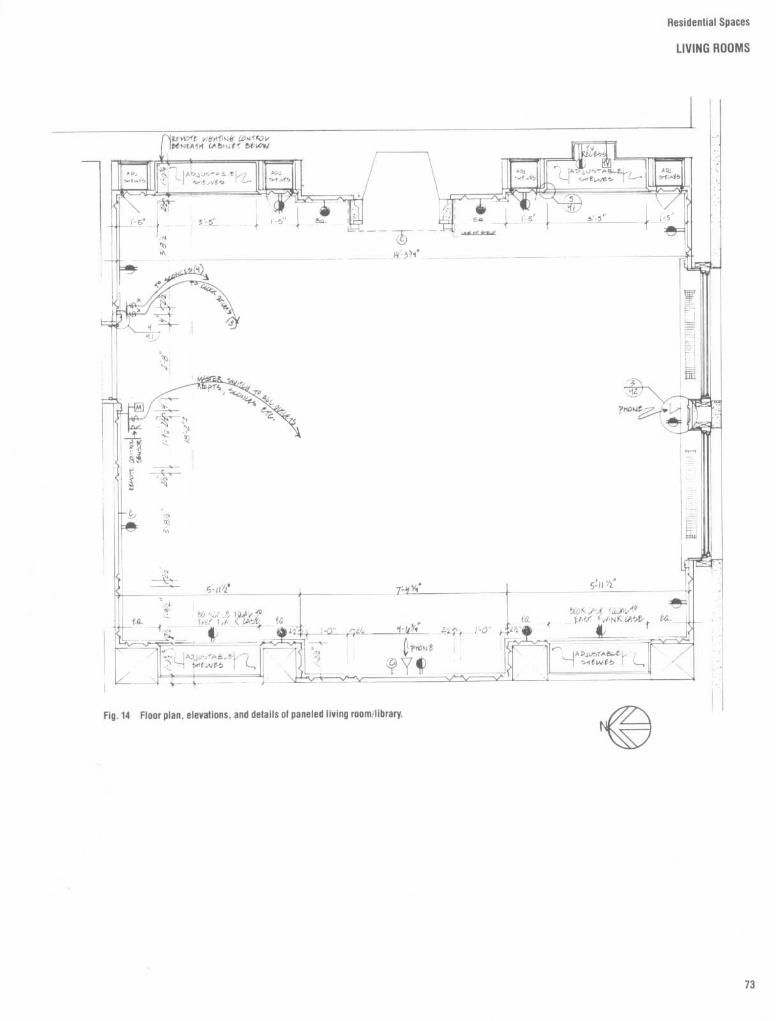
Residential Spaces
LIVING ROOMS
Plans, Elevations, and Details

Residential Spaces
LIVING ROOMSPlans, Elevations, and Details

Residential Spaces
LIVING ROOMS
Fireplace Wall Elevation and Details

Residential Spaces
LIVING ROOMSFireplace Wall Sections and Details

Figure 13 shows a plan and elevations ofmodifications to an existing fireplace . Basedon these drawings and inspection and mea-surement of existing conditions, the contrac-tor prepares and submits shop drawings forthe designer's approval . Since at least twotrades are involved, coordination of thetrades by the contractor and a thorough
review of the shop drawings by both contrac-tor and designer are essential . It is important,also, that modifications conform with allapplicable codes . The extent of hearth exten-sion, the materials used, and the distance ofcombustible materials from the fire box areamong the numerous items governed bycodes.
Residential Spaces
LIVING ROOMSFireplace Mantle Details

Residential Spaces
LIVING ROOMSBar Delalls
Residential Spaces
LIVING ROOMS

Residential Spaces
LIVING ROOMS

Residential Spaces
LIVING ROOMS

Residential Spaces
LIVING ROOMS

Residential Spaces
LIVING ROOMS
Planning Data : Sofas

Residential Spaces
LIVING ROOMSPlanning Data : Sofas

Residential Spaces
LIVING ROOMSPlanning Data : Sofas

Residential Spaces
DINING ROOMS
Furniture Clearances
SPATIAL CHARACTERISTICS ANDARRANGEMENT
Requirement
Each living unit should contain space for thepurpose of dining . This area may be com-bined with the living room or kitchen, or maybe a separate room .
Criterion
The amount of space allocated to diningshould be based on the number of persons tobe served and the proper circulation space.Appropriate space should be provided for thestorage of china and large dining articleseither in the dining area itself or in theadjacent kitchen .Space for accommodating the following
sizes of tables and chairs in the dining areashould be provided, according to theintended occupancy, as shown :
1 or2 persons: 2 ft 6 in by 2 ft 6 in4 persons: 2 ft 6 in by 3 ft 2 in6persons. 3 ft 4 in by 4 ft 0 in or 4 ft 0 in
round8persons. 3 ft 4 in by 6 ft 0 in or 4 ft 0 in
by 4ft0in10 persons: 3 ft 4 in by 8 ft 0 in or4 ft 0 in
by 6ft0in12 persons: 4 ft 0 in by 8 ft 0 inDining chairs . 1 ft 6 in by 1 ft 6 inBuffet or storage unit : 1 ft 6 in by 3 ft 6 in
Figures 1 to 6 show the minimum require-ments of the U.S . Department of Housingand Urban Development.
Commentary
Size of the individual eating space on thetable should be based upon a frontage of 24in and an area of approximately 2 ft' . Inaddition, table space should be large enoughto accommodate serving dishes .
Desirable room for seating is a clear 42 inall around the dining table . The followingminimum clearances from the edge of thetable should be provided : 32 in for chairs plusaccess thereto, 38 in for chairs plus accessand passage, 42 in for serving from behindchair, 24 in for passage only, 48 in from tableto base cabinet (in kitchen) .
In sizing the separate dining room, provi-sion should be made for circulation throughthe room in addition to space for dining .The location of the dining area in the
kitchen is desirable for small houses andsmall apartments . This preference appearsto stem from two needs (1) housekeepingadvantages ; (2) the dining table in the kitchenprovides a meeting place for the entire family.Where only one dining location is feasible,locating the dining table in the living room isnot recommended.


Residential Spaces
DINING ROOMS
Furniture Clearances
A dining room for 12.A hutch or buffet is typically about 18" deep . A 42" wide table is common .There is space behind the chairs to edge past one side and one end, and towalk past on the other side and end. Table space is 24" per person, theminimum place setting zone . With arm chairs at the ends, allow an extra 2"foreach ; add 4" to the room length .
Minimum width for table and chairs .8'-8" for 36" wide table, 32" on one side to rise from the table and 36" on theother side to edge past A 48" long table seats 4 and requires 34 .6 ft' .
Figures 8 and 9show clearances and roomsizes for various dining arrangements . Sincethese data come from two sources, theremaybe slight disparities in suggested dimen-sions for similar conditions . Since theseillustrations are intended only as guidelinesfor preliminary planning purposes, either setof any differing dimensions can be used .
Dining space with benches.6'-6" for benches on both sides of a 36" table. A 48" long table seats 4 andrequires 26 ft' .

Residential Spaces
DINING ROOMSFurniture Clearances and Room Sizes

To assure adequate space forconvenient useof the dining area, not less than the followingclearances from the edge of the dining tableshould be observed :
32 in for chair plus access thereto38 in for chairs plus access and passage42 in for serving from behind chair24 in for passage only48 in from table to base cabinet (in
dining-kitchen)
Residential Spaces
DINING ROOMSFurniture Clearances

Residential Spaces
DINING ROOMSDining Tables and Room Sizes
ROUND TABLES
SQUARE TABLES

Residential Spaces
DINING ROOMS
Dining Tables and Room Sizes

Residential Spaces
BEDROOMS
Furniture Clearances and Arrangements
Most of the clearances and bedroom sizesshown here are minimum and intended pri-marily for preliminary planning purposes .Some building codes permit rooms of evensmaller sizes, while rooms in many privatehomes and luxury apartments are muchlarger. Moreover, in the final analysis lifestyle,the size and scale of furniture, the activitiesto be accommodated, and barrier-free designare all factors that should be taken intoaccount during the design process.
Ideally, the recommended minimum bed-room size should be 10'0"x 12"0" exclusive ofclosets, while the recommended minimumsize for a larger bedroom or master bedroomshould be 12'0" x 16'0" exclusive of closets .A larger proportion of the bedroom floor
area is occupied by furniture than is the casewith any other room ; windows and doorsaccount for a large percentage of the wall andpartition space. These two factors compli-cate the planning of bedrooms, especiallywhen the rooms are small.
Because of the room layout, some bed-rooms with smaller areas better meet theneeds than larger ones . The location ofdoors, windows, and closets must be prop-erly planned to allow the best placement ofthe bed and other furniture .
Privacy, both visual and sound, are desir-
able for the bedroom. Children's bedroomsshould be located away from the living room,because conversation in the living roomprevents the children from sleeping . Closetsshould be used between all bedrooms wher-ever possible .
Each child needs a space that is his or herown to develop a sense of responsibility anda respect for the property rights of others .The ideal plan would provide a bedroom foreach child, but since this is not alwayspossible, there should be a bed for each .The minimum room width shall be deter-
mined by the space required for the bed,activity space, and any furniture facing thebed . Widths less than 9'0"will usually requireextra area to accommodate comparablefurniture .
Aside from sleeping, the bedroom is thecenter of dressing and undressing activities .An interrelationship exists between dress-ing, storage of clothes, and the bedroom.
Inevitably, in a small apartment, it is notonly economical but necessary to plan theuse of the bedroom for more than oneactivity. It is essential to incorporate in thebedroom other functions such as relaxation,work, or entertainment .A master bedroom should accommodate
at least one double bed 4'6" x 6'6" or two
single beds 3'3" x 6'6" each, one crib 2'4" x1'5" if necessary, one dresser 3'6" x 1'10",one chest of drawers 2'6" x 1'10", one or twochairs 1'6" x 1'6" each, two night tables, andpossibly a small desk or table 1'6" x 3'0" .Figures 1 to 3 illustrate three configurationsand the furniture clearances and room sizesrequired .Ample storage is essential. Each bedroom
requires at least one clothes closet . Formaster bedrooms, at least five linear feet ofcloset length is needed . For secondary bed-rooms, at least three linear feet is needed .Clothes closets require a clear depth of twofeet .
Each bedroom shall have at least onecloset that meets or exceeds the followingstandards
1 . Depth : 2 feet clear2 . Length (for primary bedroom) : 5 linear
feet clear3. Height :
a . At least 5'4" clear hanging spaceb. Lowest shelf shall not be over 6'2"
above the floor of room4. One shelf and rod with at least 12
inches clear space above shelf5. At least one-half the closet floor shall be
level and not more than 12 inches above floorof adjacent room

Residential Spaces
BEDROOMS
Furniture Clearances and Arrangements
FURNITURE CLEARANCES
To assure adequate space for convenient useof furniture in the bedroom, not less than thefollowing clearances should be observed(Figs. 4 and 5) :
42 in at one side or foot of bed fordressing
6 in between side of bed and side ofdresser or chest
FURNITURE ARRANGEMENTS
The location of doors and windows shouldpermit alternate furniture arrangements .
36 inches in front of dresser, closet, andchest of drawers
24 in for major circulation path (door tocloset, etc.)
22 in on one side of bed for circulation12 in on least used side of double bed .
The least-used side of a single or twin bedcan be placed against the wall except inbedrooms for the elderly

Residential Spaces
BEDROOMS
General Plannino Data
Fig . 8
Occupancy of a bedroom by more than two persons is notrecommended . In cases where budgetary and/or space limitationsoffer no alternative, however, a dormitory arrangement may benecessary. The U .S . Department of Housing and Urban Develop-ment recommends the arrangement illustrated in this diagram .
.-Mm
Fig . 7
Double occupancy bedroom . Net area :14 .7 MI (160 ft2). The most likely occupants ofthis type of bedroom are adults, school-age children of the same sex, children of differentsexes who are less than 9 years old, and preschoolers .

Residential Spaces
BEDROOMSBuilt-In Storage Details

liesidential Spaces
BEDROOMS
Built-In furniture

Residential Spaces
BEDROOMSBuilt-In Furniture

Residential Spaces
BEDROOMS
Built-In Furniture

Residential Spaces
BEDROOMS
Built-In Wardrobe Details

Residential Spaces
BEDROOMSBuilt-In Wardrobe Details

Residential Spaces
BEDROOMSPlan and Elevation of Walk-In Closet

Residential Spaces
BEDROOMS
Built-In Furniture and Closet Details

Residential Spaces
BEDROOMSClosets

Residential Spaces
BEDROOMS
Ciosels

Residential Spaces
BATHROOMSPlanning Data and Fixture Arrangements
A bathroom should have enough area toaccommodate a lavatory, a water closet, anda bathtub or shower. Arrangement for fix-tures should provide for comfortable use ofeach fixture and permit at least 90° doorswing unless sliding doors are used .The bathroom should be convenient to the
bedroom zone, and accessible from the livingand work areas . Linen storage should beaccessible from the bathroom, but not nec-essarily located within the bathroom .
Each complete bathroom should be pro-vided with the following :
1 . Grab-bar and soap dish at bathtub2 . Toilet paper holder at water closet3 . Soap dish at lavatory (may be integral
with lavatory)4 . Towel bar5 . Mirror and medicine cabinet or equiv-
alent enclosed shelf space6 . In all cases where shower head is
installed, provide a shower rod or showerdoor
Each half-bath should be provided withitems 2 to 6 listed above .
DOUBLE LAVATORY CLEARANCES
in Cm
A 15-18 38.1-45.7B 28-30 71 .1-76.2C 37-43 94.0-109 .2D 32-36 81 .3-91 .4E 26-32 66.0-81 .3F 14-16 35.6-40.6G 30 76.2H 18
45.721-26 53.3-66.0
MINIMUM SHOWERCLEARANCES
in
A 54B 12C
42 min .
Cm
137.230.5
106.7 min .D 18
45.7E
36 min .
91 .4 min .F 30 76.2G 24
61 .0H
12 min .
30.5 min .15
38 .1J 40-48 101 .6-121 .9I( 40-50 101 .6-127.0L
72 min .
182.9 min .
BIDET AND WATER CLOSET
in
A
12 min .B
28 min .C
24 min .D
52 min .E 12-18F 12G 40H 18I 30
Cm
30.5 min .71 .1 min .61 .0 min .132 .1 min .30.5-45.7
30.5101 .645.776.2

in cm
A 48
121 .9g 30 76.2C 19-24 48.3-61 .0
27 min .
68 .6 min .18
45.737-43 94 .0-109 .2
G
72 max .
182.9 max .H 32-36 81 .3-91 .4
69 max .
175.3 max .16-18 40.6-45 .726-32 66.0-81 .3
L 32
81 .3M 20-24 50.8-61 .0
Residential Spaces
BATHROOMSPlanning Data
Figure 1 deals primarily with some of themore critical male anthropometric considera-tions. A lavatory height above the floor of 37to 43 in, or 94 to 109.2 cm, is suggested toaccommodate the majority of users . It shouldbe noted, however, that common practice isto locate the lavatory in the neighborhood of31 in above the floor In order to establish thelocation of mirrors above the lavatory, eyeheight should be taken into consideration .
Figure 2 explores, in much the samemanner, the anthropometric considerationsrelated to women and children . Given thegreat variability in body sizes to be accommo-dated within a single family, a strong case canbe presented for the development of a heightadjustment capability for the lavatory. Untilthat is developed, there is no reason, oncustom installations, why the architect or ""interior designer cannot take anthropometricmeasurements of the client to ensure properinterface between the user and the lavatory.

Residential Spaces
BATHROOMSTypical Plans and Fixture Arrangements

Residential Spaces
BATHROOMS
Typical Plans and Fixture Arrangements

Residential Spaces
BATHROOMSTypical Plans and Fixture Arrangements

Residential Spaces
BATHROOMSTypical Plans and Fixture Arrangements

Residential Spaces
BATHROOMSCustom Designs
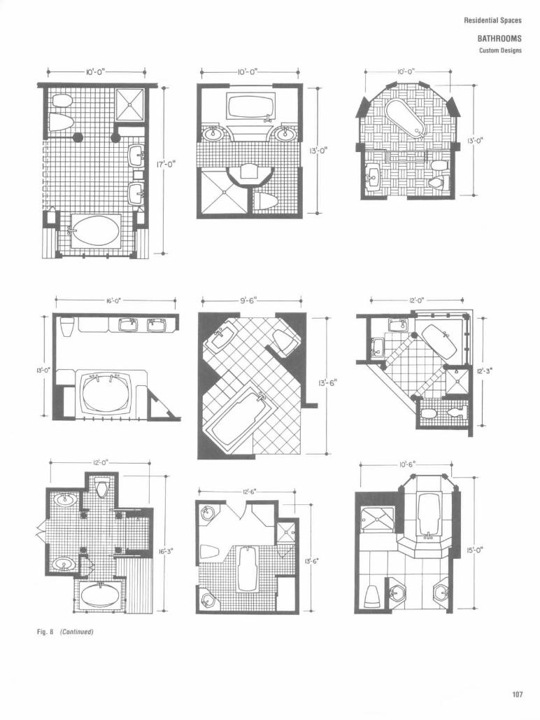
Residential Spaces
BATHROOMSCustom Designs

Hesiaenuai zipaci
BATHROOMS
Custom Designs

Residential Spaces
BATHROOMSLavatory Types and Dimensions

Residential Spaces
BATHROOMSLavatory Types and Dimensions

Residential Spaces
BATHROOMS
Lavatory types and Dimensions
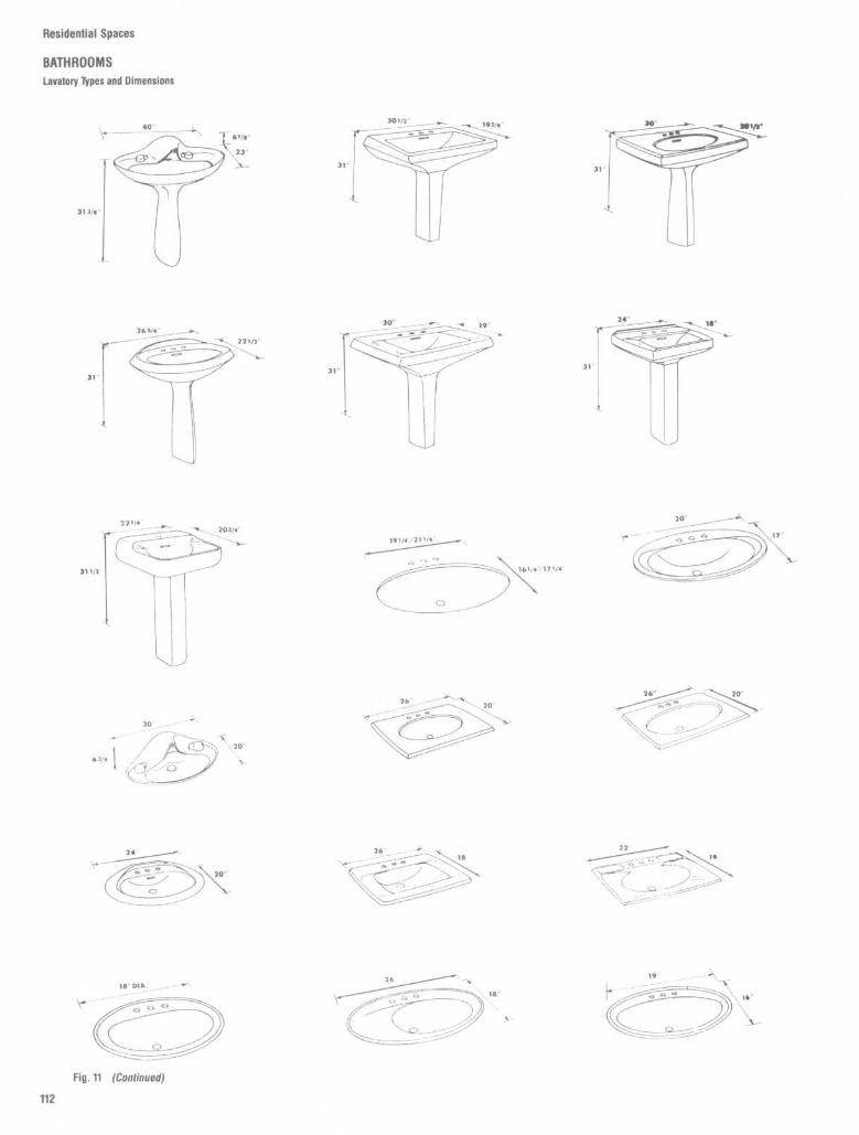
Residential Spaces
BATHROOMSLavatory Types and Dimensions

Residential Spaces
BATHROOMS
Whirlpool Types and Dimensions

Residential Spaces
BATHROOMSBathtub Types and Dimensions

Hesidential Spaces
BATHROOMS
Watereloset Types and Dimensions

Residential Spaces
BATHROOMSBidet Types and Dimensions

Residential Spaces
BATHROOMSAccessories

Residential Spaces
BATHROOMS
Plans, Elevations, and Details

Residential Spaces
BATHROOMSPlans, Elevations, and Details

Residential Spaces
BATHROOMS
Plans, Elevations, and Details

Residential Spaces
BATHROOMSPlans, Elevations, and Details

Residential Spaces
BATHROOMS
Plans, Elevations, and Details

Residential Spaces
BATHROOMSPlans, Elevations, and Details

flesidential Spaces
BATHROOMS
Plans, Elevations, and Oelalls

Residential Spaces
BATHROOMSVanities

Residential Spaces
BATHROOMS
Vanities

Residential Spaces
BATHROOMSVanities
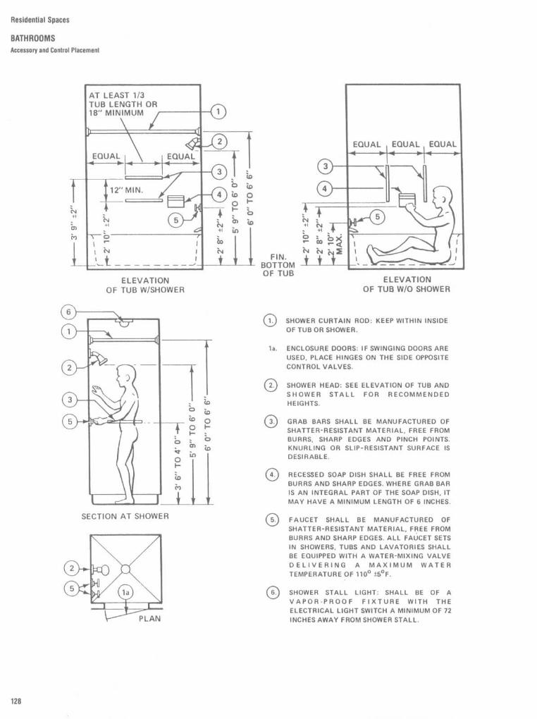
Residential Spaces
BATHROOMSAccessory and Control Placement
SHOWER CURTAIN ROD: KEEP WITHIN INSIDEOF TUB OR SHOWER .
1a .
ENCLOSURE DOORS: IF SWINGING DOORS AREUSED, PLACE HINGES ON THE SIDE OPPOSITECONTROL VALVES .
O2 .
SHOWER HEAD : SEE ELEVATION OF TUB ANDSHOWER STALL FOR RECOMMENDEDHEIGHTS.
O3 .
GRAB BARS SHALL BE MANUFACTURED OFSHATTER-RESISTANT MATERIAL, FREE FROMBURRS, SHARP EDGES AND PINCH POINTS .KNURLING OR SLIP-RESISTANT SURFACE ISDESIRABLE.
RECESSED SOAP DISH SHALL BE FREE FROMBURRS AND SHARP EDGES. WHERE GRAB BARIS AN INTEGRAL PART OF THE SOAP DISH, ITMAY HAVE A MINIMUM LENGTH OF 6 INCHES .
FAUCET SHALL BE MANUFACTURED OFSHATTER-RESISTANT MATERIAL, FREE FROMBURRS AND SHARP EDGES. ALL FAUCET SETSIN SHOWERS, TUBS AND LAVATORIES SHALLBE EQUIPPED WITH A WATER-MIXING VALVEDELIVERING A MAXIMUM WATERTEMPERATURE OF 110° i5°F.
6O. SHOWER STALL LIGHT: SHALL BE OF AVAPOR-PROOF FIXTURE WITH THEELECTRICAL LIGHT SWITCH A MINIMUM OF 72INCHES AWAY FROM SHOWER STALL.

Residential Spaces
BATHROOMS
Vanities ; Lavatory Counters

Residential Spaces
BATHROOMSLavatory Counters

Residential Spaces
BATHROOMSLavatory Counters

Residential Spaces
BATHROOMS
Bathtub and Shower Details
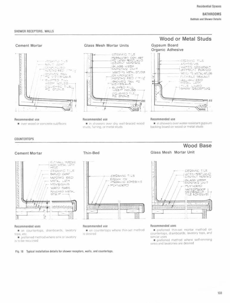
Residential Spaces
BATHROOMS
Bathtub and Shower Details
SHOWER RECEPTORS, WALLS
Wood or Metal StudsCement Mortar
Glass Mesh Mortar Units
Gypsum BoardOrganic Adhesive
Recommended use
Recommended use
Recommended use0 over wood or concrete subfloors
n in showers over dry, well-braced wood
n in showers over water-resistant gypsumstuds, furring, or metal studs
backing board on wood or metal studs
COUNTERTOPS
Wood BaseCement Mortar
Thin-Bed
Glass Mesh Mortar Unit
Recommended uses
Recommended use
Recommended uses
m on countertops, drainboards, lavatory
ra on countertops where thin-set method
m preferred thin-set mortar method on
tops, etc.
is desired
countertops, drainboards, lavatory tops, andm preferred method where sink or lavatory
similar usesis to be recessed
m preferred method where self-rimmingsinks and lavatories are desired
Fig . 18
Typical installation details for shower receptors, walls, and countertops.

Residential Spaces
BATHROOMS
Bathtub and Shower Details

Residential Spaces
BATHROOMS
Whirlpool Details

Residential Spaces
BATHROOMS
Ceramic Tile Details
Recommended usesr+ for alteration of ceramic-tiled areas
where modernization or a change of design isdesired in residences, motels and hotels,restaurants, public rest rooms, etc.0 also applicable to smooth walls of mar-
ble, stone, slate, etc
Requirements0 existing installation must be sound, well
bonded, and without major structural cracks
Materials, grouting, expansion joints,installation specifications
for organic adhesive installation seeMethod W223
for Dry-Set or latex-portland cementmortar installation see Method VV202
E for epoxy adhesive installation refer tomanufacturer's literature
Fig.19
Typical installation details fortile over tile .
Recommended usesfor alteration of ceramic-tiled areas
where modernization ora change of design isdesired in residences, motels and hotels,restaurants, public rest rooms, etc .
ra also applicable to smooth floors of ter-razzo, stone, slate, etc.
TILE OVER TILE
Interior Walls
Interior Floors

ACCESSIBILITY
It is essential that the design of interiorspaces, as well as exterior spaces, be re-sponsive to the needs of those having phys-ical disabilities . There is a proliferation ofstate and local legislation in this regard, and,more recently, federal legislation (Americanswith Disabilities Act of 1990), that providesdesign guidelines and requirements . The
designer should become familiar with thosecodes and other requirements in her or hisarea prior to initiation of design and, wherepossible, go beyond the very minimumstandards .The design of the bathroom is perhaps one
of those areas where the interface betweenthe physically disabled and the interior space
is the most critical . Accordingly, on this pageand the following pages are design guide-lines prepared by the Veterans Administra-tion and the U .S . Department of Housing andUrban Development.
recommended self-supporting shelf andcountertop
- recommended addi-tional connection forhand-held showerhead
1-1
standard S'-0" bathtub
-reinforced areas forpossible future grabbar installation
vanity cabinetremoved andprotection coverinstalled
hand-held showerand grab barsadded as needed
clamp on tub seatadded as needed
Residential Spaces
BATHROOMS
Adaptable Bathrooms

This sample bathroom meets theminimum space requirements ofboth ANSI and UFAS ; note,however, that the space is verysmall and many wheelchair userswill have difficulty using such abathroom . More space should beallocated when possible .
Residential Spaces
BATHROOMS
Adaptable Bathrooms

Residential Spaces
BATHROOMSAdaptable Bathrooms

Residential Spaces
BATHROOMS
Adaptable Bathrooms
Standard Bathtub with Removable Seat
Standard Bathtub with Built-in Seat
ANSI Minimum Roll-in Shower
Preferred Deeper Roll-in Shower

Residential Spaces
BATHROOMS
Adaptable Bathrooms
BATHROOM TYPE WITH 24"
REMOVABLE VANITY CABINET
POWDER RM . PLAN WITH 27" REMOVABLEVANITY CABINET
BATHROOM PLAN W/20" LAVATORY

Iil,'Slllf'.ilil~Sl ;;(IdCC'=~
BATHROOMSAdaptable Bathrooms
BATHROOM PLAN WITH 24"
REMOVABLE VANITY CABINET
x _ TkE Out EDGE of NE WATER CLOSET *kl NOT EXTO4DNTO THE CLEAR SPACE REDWRED FROM THE DOOR OPONr4G.
36"x 36'' ADAPTABLE SHOWER STALL
MINIMUM BATHROOM REQUIRED
W/ADDITIONAL SHOWER

Residential Spaces
BATHROOMSWheelchair Accessible Design

Residential Spaces
BATHROOMS
Wheelchair Accessible Clearances
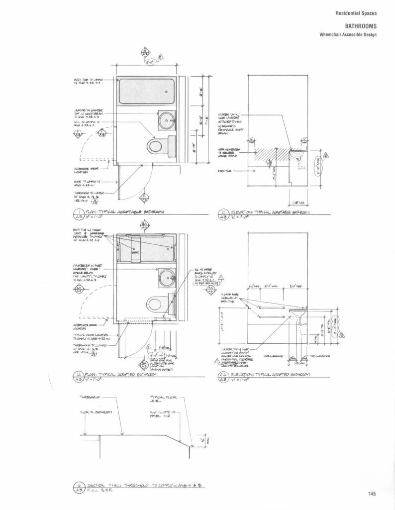
Residential Spaces
BATHROOMSWheelchair Accessible Design

Hesidenlial tip icc~
BATHROOMSWheelchair Accessible Clearances

Residential Spaces
BATHROOMS
Wheelchair Accessible Clearances

Residential Spaces
BATHROOMSWheelchair Accessible Design

RANGE CENTER
Residential Spaces
KITCHENSAnthropometric Data
The height of a kitchen workcounter, theproper clearance between cabinets or ap-pliances for circulation, the accessibility tooverhead or undercounter storage, andproper visibility are among the primary con-siderations in the design of cooking spaces .All must be responsive to human dimensionand body size if the quality of interfacebetween the user and thecomponents of theinterior space are to be adequate . In estab-lishing clearances between counters, themaximum body breadth and depth of theuser of larger body size must be taken intoaccount as well as the projections of theappliances . Refrigerator doors, cabinet draw-ers, dishwashing machine doors, and cabinetdoors all project to some degree in theiropenposition into the space within which the usermust circulate and must be accommodated .
Standard kitchen counter heights man-ufactured are all about 36 in, or 91 .4 cm . Butsuch a height does not necessarily accom-modate the bodydimension of all users for alltasks . Certain cooking activities, for exam-ple, maybe more efficiently performed froma standing position, but with a counter heightless than 36 in . In overhead cabinets theupper shelves are usually inaccessible to thesmaller person, while the lower shelves areusually inaccessible to most without bendingor kneeling . The logical answer is the devel-opment of kitchen cabinet systems capableof total adjustability to accommodate thehuman dimension of the individual user. Sucha system could accommodate not only thoseof smaller and larger body size, but alsoelderly and disabled people .
Figure 1 provides some general an-thropometric data for establishing basicheights of cabinetry and appliances abovethe floor Figures 2 and 3 show in more detailthe interface of the human body and thekitchen environment .
in
CM
48 min .
121 .9 min .40
101 .6C
15
38.1 min .21-30 53 .3-76.2
E 1-3 2 .5-7 .615 min .
38.1 min .G 19 .5-46 49.5-116 .8H
12 min .
30 .5 min .I
17.5 max .
44 .5 maxJ 96-101 .5 243.8-257.8
24-27 .5 61 .0-69 .9L 24-26 61 .0-66 .0M 30 76 .2N
60 min .
152 .4 min .35-36.25 88 .9-92.1
P
24 min .
61 .0 min .
0
35 max .
88 .9 max .

Residential Spaces
KITCHENSAnthroporrretric Data
Figures 2 and 3 illustrate the clearancesrelated to range centers . Figure 2 indicates aminimum clearance between appliances of48 in, or 121 . 9 cm . The anthropometric basisfor the clearances are amplified in Fig . 3 .The 40-in, or 101 .6-cm, wall oven workzone
clearance is adequate to accommodate theprojected wall oven door, in addition to themaximum body depth dimension of the userThe standing figure shown in broken line,however, indicates both dimensionally andgraphically that the 40-in clearance will notpermit comfortable circulation when ap-pliances on both sides are in operation at thesame time . The range workzone clearance,also 40 in, is adequate to accommodate theopen range door and the body size of thekneeling user.An extremely important, but frequently
overlooked, anthropometric consideration inkitchen design is eye height . In this regard,the distance from the top of the range to theunderside of the hood should allow the rearburners to be visible to the user.
in Cm
48 min .
121 .9 min .40
101 .6C
15
38 .1 min .
21-30 53.3-76.21-3 2.5-7.6
15 min .
38.1 min .G 19.5-46 49.5-116.8
H
12 min .
30.5 min .
I
17.5 max .
44.5 max
96-101 .5 243.8-257.824-27 .5 61 .0-69.9
L 24-26 61 .0-66 .0M 30 76.2N
60 min .
152 .4 min .35-36.25 88 .9-92 .124 min .
61 .0 min .0
35 max .
88 .9 max .
RANGE CENTER

Residential Spaces
KITCHENS
Typical Layouts
The U-shaped plan is the most efficient .When not broken, it provides the opportunityand floor space for several simultaneousactivities . The corridor or gallery kitchen istypically accessible from both ends, oftenconverting it from a work space to a corridorIt sometimes is closed off on one end,thereby creating a variation of the U-plan,which although small can produce a fairlycomfortable kitchen.The broken U-shaped plan often results
from the necessity of locating a door alongone or two of the three walls of a typical U-shaped scheme . The resulting through trafficreduces the compactness and efficiency ofthe plan .The typical L-shaped kitchen allows for the
location of a small breakfast area in theopposite corner.
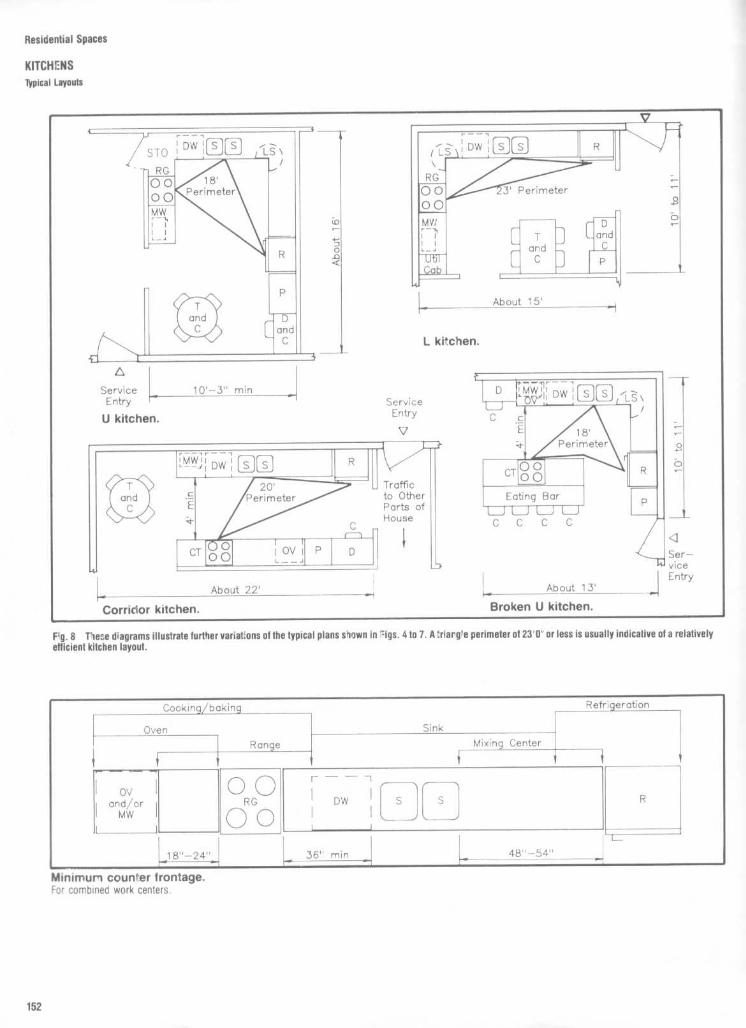
Residential Spaces
KITCHENSTypical Layouts
F;,g . 8
These diagrams illustrate further variat'ons of the typical plans shown in =igs . 4 to 7 . A'riargle perimeter of 23'0" or less is usually indicative of a relativelyefficient kitchen layout .
Minimum counter frontage .For combined work centers .
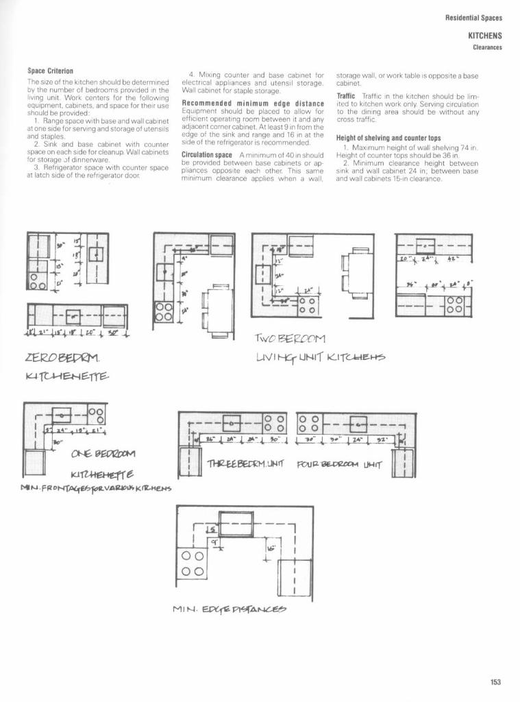
Residential Spaces
KITCHENS
Clearances
Space Criterion
The size of the kitchen should be determinedoy the number of bedrooms provided in thewing unit . Work centers for the followingequipment, cabinets, and space for their useshould be provided :
1 . Range space with base and wall cabinetat one side for serving and storage of utensilsand staples.2. Sink and base cabinet with counter
space on each side forcleanup. Wall cabinetsfor storage )f dinnerware .3. Refrigerator space with counter space
at latch side of the refrigerator door.
4 . Mixing counter and base cabinet forelectrical appliances and utensil storage.Wall cabinet for staple storage.
Recommended minimum edge distanceEquipment should be placed to allow forefficient operating room between it and anyadjacent corner cabinet. At least 9 in from theedge of the sink and range and 16 in at theside of the refrigerator is recommended.
Circulation space
Aminimum of 40 in shouldbe provided between base cabinets or ap-pliances opposite each other This sameminimum clearance applies when a wall,
storage wall, or work table is opposite a basecabinet .
Traffic Traffic in the kitchen should be lim-ited to kitchen work only. Serving circulationto the dining area should be without anycross traffic .
Height of shelving and counter tops1 . Maximum height of wall shelving 74 in .
Height of counter tops should be 36 in .2. Minimum clearance height between
sink and wall cabinet 24 in ; between baseand wall cabinets 15-in clearance.

Residential Spaces
KITCHENS
Storage and Cabinets
KITCHEN STORAGE
Each kitchen or kitchenette should have (1)accessible storage space for food and uten-sils, (2) sufficient space for the averagekitchen accessories, (3) sufficient storagespace for those items of household equip-ment normally used and for which storage isnot elsewhere provided .
CLEARANCES OVER COOKINGRANGES
In Fig. 10, dimension A: 2 ft 6 in minimumclearance between the top of the range andthe bottom of an unprotected wood or metalcabinet, or 2 ft 0 in minimum when thebottom of a wood or metal cabinet isprotected .Dimension B : 2 ft 0 in minimum when
hood projection X is 18 in or more, or l ft 10 inmin. when hood projection X is less than18 in .Dimension C : not less than width of range
or cooking unit .Dimension D : 10 in minimum when verti-
cal side surface extends above countertops .Dimension E : when range is not provided
by builder, 40 in minimum .Dimension F : Minimum clearance should
be not less than 3 in .Cabinet protection should be at least 114 in
asbestos millboard covered with not lessthan 28-gauge sheet metal (0 .015 stainlesssteel, 0.024 aluminum, or 0.020 copper).
Clearance for D, E, or F should be not lessthan listed UL or AGA clearances .

Above a sink, plan for a minimum of22 in . to the bottom of a wall cabi-net . Since the wall behind a sinkoften holds a window, measurementfor a cabinet is academic . But if wallspace is minimal, a cabinet over thesink makes good sense.
The use of large pans, pancake flipsand similar cooking maneuversdictate a distance of 30 in . betweenrangetop and wall cabinet bottom .A fan mounted in the wall is themeans here to exhaust cookingfumes to the outside.
A range of 15 in . to 18 in, is the prop-er span between standard baseand wall cabinets. Opt for the 15 in .distance if you are 5 ft . 4 in . or less ;a wider span if you're taller. Thehighest shelf : 6 ft . from the floor, isa reachable distance .
Kitchen activities become tiresomein poor light. A single fixture, cen-tered on the ceiling is insufficient .Your need for light is greatest overthe work centers A good light therereduces the danger of cutting your-self ; eases the task of monitoringcolor changes during a mix, and soon . The best place to install fixturesfor this purpose is beneath the wallcabinets (with a shield to preventglare when you're seated in thekitchen) . A workable alternative isfound in fixtures installed in anextended soffit . Plan for light abovea rangetop and over the sink, aswell . Choose incandescent, deluxewarm white or deluxe cool whitelamps for the fixtures to avoid poorcolor rendition.
TABLE 1
Minimum Kitchen Storage Required
ItemTotal shelving in wall and basecabinets
24Shelving in either wall or basecabinets
10Drawer area
4Countertop area
,
5
Item
40 to 60 ft' Area -Kitchenette
0-bedroom living unit,* ft'
60 ft2 Area and Over - Kitchen
1- and 2-bedroom livingunits, ft'
Total shelving in wall and basecabinets
48Shelving in either wall or basecabinets
toDrawer area
8Countertop area
10
1-bedroom living unit,* ft2
30
1256
3-and 4-bedroom livingunits, ft2
54
201012
*Kitchen unit assemblies serving the kitchen function and occupying less than 40 ft 2 area in0-BR living units shall not be less than 5 ft in length and shall provide at least 12 ft2 of totalshelving in wall and base cabinets . Drawer and countertop space shall also be provided . Noroom count is allowable for this type facility.
Residential Spaces
KITCHENSStorage and Cabinets
Utensil and General Storage
Space for utensils includes storage fordishes, pots and pans, utensils, and ap-pliances . With the increased use of suchelectrical appliances, their storage becomesa significant problem. General storage re-quires space for linens, towels, and kitchensupplies . Included in this category arebrooms, mops, and other cleaning equip-ment and supplies .

Residential Spaces
KITCHENSCabinet Dimensions
Example of the proper dimensionallimits and relative placement ofkitchen base cabinets and wall cabinets

Residential Spaces
KITCHENSCabinet Dimensions

Residential Spaces
KITCHENSCabinet Sizes
FRAMED FRAMELESS
F.
-mo.,-011Ln e
WALL CABINETSWall cabinets are available in heights of42 ;' 30;' 24 ;' 18;15,°and 12" Most cabinets areavailable in widths ranging from 9" to 48,° in3" increments . Framed wall cabinets are 12"
WALL BLIND CORNER CABINETSWall blind corner cabinets are available inheights of 47,'30" and 24" Most wall blindcorner cabinets are available in widths of 24;'27 : 30 ;' 33;' 36 ; 42,"and 48"
BASE CABINETSAll base cabinets are 34Y2' tall . Most areavailable in widths ranging from 9" to 48 ;' in3" increments. Framed base cabinets are 24"deep, not including doors . Frameless basecabinets are 24'/<" deep, including doors.
deep not including doors. Frameless wallcabinets are 12Y<" deep including doors .
DOUBLE-FACE WALL CABINETSDouble-face wall cabinets are available inheights of 30:'24" and 18" Most are availablin widths of 18 :'24:'3Q'36:'42" and 48"Framed cabinets are 13' 5/16' deep withdoors. Frameless are ',3Y2" deep with door,,
Four-drawer base cabinets are available inwidths ranging from 12" to 24 ; in 3" incre-ments . Frameless base cabinets are alsoavailable in a three-drawer style in widthsof 30" and 36''
BASE BLIND CORNER CABINETSAll base blind corner cabinets are 34'/l'high . Most are available in widths of 24:'30 :'36; 39,° 42,"and 48"
SPECIALTY CABINETSLazy Susans :36"-WideRange Hoods : (framed only)36" & 30"-WideWall What-Not Shelves (framed only)30"-HighBase Open Shelves : (framed only)34'/1'-HighPantries : (framed only)36" x 66"Utility Cabinets : (framed)24" x 66"18" x 66"In 12" and 24" DepthsUtility Cabinets : (frameless)24" x 65%2"18" x 65Y1'In 12'/<<" and 24'/" Depths
Tilt-Out Range Hoods : (frameless only)30" x 24"Glass Door Wall Cabinets : (frameless only)30" & 36"-WideMicrowave Cabinets : (framed only)30"x21"Microwave Shelves :30" x 221/8" (framed)30" x 18" (frameless)Oven Cabinets : (framed)27" x 66"30" x 66"33" x 66"Oven Cabinets : (frameless)27" x 65'/z"30" x 65'/:"33" x 65'/:"Up to six 6" drawers can be addedto frameless oven cabinets

Residential Spaces
KITCHENS
Cabinet Types and Dimensions

Residential Spaces
KITCHENS
Cabinet Types and Dimensions

Residential Spaces
KITCHENS
Cabinet Types and Dimensions

Residential Spaces
KITCHENSCabinet Types and Dimensions

Residential Spaces
KITCHENS
Cabinet Types and Dimensions

Residential Spaces
KITCHENS
Cabinet Types and Dimensions

Residential Spaces
KITCHENS
Cabinet types and Dimensions
I
OXA,
Or
i
~R OhoR1'~V O W
~h~
;
IRt;t7 Or4K
ti-'C n
II-
liltN
i
~
I
0
51k"~ I~-Glik'_ n
WA-
z'-21/4" 7~rk"
-At'5L vAM .
-
t7RhWER
.ICE ~ -'
I
s~!F "." . j I
TbEr p,
'=Lp~
rv
sOAK CIA!i
4
r
I
~~FV
I-a.

Residential Spaces
KITCHENS
Cabinet Details

Residential Spaces
KITCHENS
Cabinet Details

Residential Spaces
KITCHENSCabinet Details

Residential Spaces
KITCHENS
Cabinet Details

Residential Spaces
KITCHENS
Sink Types and Dimensions

Residential Spaces
KITCHENS
Appliances
Ranges and Built-In Ovens
Freestanding ranges and built-in ovens comein a variety of sizes and configurations . Someof the larger ranges consist of modularcooktops providing anywhere from two toseven heating elements as well as modulargrills, griddles, and even downdraft built-inventilators . Normally, a minimum clearanceof 30" is required above any range orcooktop,but the designer is cautioned to carefullyverify local code requirements . Manufactur-ers' specifications should be carefully re-viewed for rough opening requirements andany venting requirements, particularly forself-cleaning ovens .
Dishwashers
Built-in, freestanding, and undersink dish-washers are fairly well standardized in termsof overall dimensions . Access to plumbingand waste lines is the major consideration, asis the method of securing the dishwasher inorder to minimize vibration .
Refrigerators
Refrigerator door swings and clearances areof critical importance . While a 90°door swingmay provide sufficient room for a person toobserve storage within a refrigerator orfreezer, a 180° door swing may be required toclean a refriqerator and remove storaqe bins .
This is particularly true of the side-by-sidedoor configuration . In addition, adequateclearance should be allowed between thesides and top of the refrigerator and anyadjoining cabinetwork, especially if a built-inlook is desired. The designer should checkrequirements with the manufacturer.While these drawings can be used for
preliminary planning, final dimensions andclearance must be verified with the manufac-turer Often overlooked are clearances forrefrigerator handles or pulls as well as coilsmounted at the rear of the refrigerator.

Residential Spaces
KITCHENS
Appliances
Note : Dimensions shown are for planning purposes only.

Residential Spaces
KITCH=NS
Appliances
Note : Dimensions shown are for planning purposes only.

Residential Spaces
KITCHENSCountertops

Residential Spaces
KITCHENS
Countertops

Residential Spaces
KITCHENS
Plans and Elevations

Residential Spaces
KITCHENSPlans and Elevations

Residential Spaces
KITCHENS
Wheelchair Accessible Design

Residential Spaces
KITCHENS
Wheelchair Accessible Design

Residential Spaces
KITCHENS
Wheelchair Accessible Design

Residential Spaces
KITCHENSWheelchair Accessible Design
Requirements
The ANSI and UFAS standards require ac-cessible and adaptable features which makethe kitchen usable by most people . The fixedaccessible features specified in ANSI 4.32.5and UFAS 4 .34 .6 include requirements fordoors, clearances, clear floor space, ap-pliances, storage, controls, and knee space .The adaptable features are removable basecabinets at knee spaces and counters thatcan be adjusted in height or fixed at a lowerthan standard height .The adaptable features for kitchens spec-
ified in the standards are shown in Figs . 13and 14. In Fig. 13, the kitchen is shown in astandard configuration with the counterheight at 36 inches and the knee spacescovered with base cabinets .
In Fig . 14, the kitchen has been adapted byexposing the knee spaces and lowering thework surface and sink counter segments . Noother changes have been made to thekitchen.
Since removable base cabinets and adjust-able height counters are not now productsthat are readily available for purchase, theyare usually custom-made items.
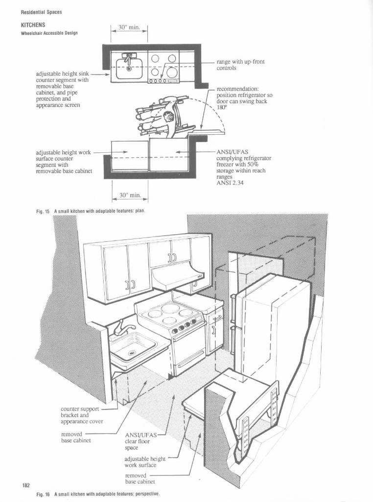
Residential Spaces
KITCHENS
Wheelchair Accessible Design

hesicenlial Spaces
KITCHENSWheelchair Accessible Design
The kitchen shown in Figs . 17 and 18 is anexample of a more elaborate kitchen havingANSI/UFAS accessible/adaptable features .This kitchen exceeds the ANSI/UFAS mini-mum requirements .

Residential Spaces
KITCHENS
Wheelchair Accessible Design
Work Surfaces
People who use wheelchairs and other peo-ple who must or wish to sit down whilepreparing food need at least one work sur-face lower than the usual 36-in-high counter(Fig . 19).The standards (ANSI 4.32.5 .4 and UFAS
4.34.6 .4) require that at least one 30-in-wide,adjustable-height work surface be providedin an adaptable kitchen, although a wider sizeis preferred. The wider work surface pro-vides space for pots, dishes, and other uten-sils as well as small appliances, and makes iteasier to work on several things at once or tocook using many ingredients .

Work surfaces at ovens If a wall oven isinstalled, a lowered work surface with kneespace should be installed next to the walloven . The standards specify that when thewall oven is not self-cleaning, a knee spacemust be located next to the oven to permit adisabled person in a wheelchair to pull upclose enough to clean the oven .
Even if a self-cleaning oven is installed,locating the knee space next to the ovenmakes it easier and safer for a disabledperson to remove hot items from the oven .When an oven with a side-opening door is
used, a pull-out shelf located beneath theoven must be installed . The shelf is used as atransfer surface for dishes as they are placedinto or taken out of the oven . When notneeded, the shelf is pushed back into theoven cabinet (Fig . 23). When an oven with adrop-front door is used (Fig . 21), the pulloutshelf is not needed because the door servesas a transfer shelf.See ANSI 4.32 5 7 and UFAS 4.34.6 .7 for
dimensions and details of oven .
Residential Spaces
KITCHENSWheelchair Accessible Design

Residential Spaces
KITCHENS
Wheelchair Accessible Design
Cooktops in Adjustable HeightCounter Segments
ANSI 4.32 .5 .6 and UFAS 4.34.6 .6 permit useof a standard range if the controls complywith ANSI 4.25 or UFAS 4 .27 . The controlsmust be placed along the front or the side ofthe range so that a seated person need notreach across a hot burner to adjust thecontrols (Fig . 24).Some wheelchair users cannot use con-
ventional ranges because the surface is toohigh and there is no knee space for maneu-vering . Cooktops in lowered counter seg-ments with knee space below allow somewheelchair users to get close enough to
operate the controls and move heavy potsand pans (Fig . 25) .
Cooktops with smooth surfaces are pre-ferred by people with limited hand and armstrength because they can slide pots of hotfood on and off the cooktop rather than liftingthem over raised burners and knobs.When a cooktop is installea in a lowered
counter, the width of the counter segmentand knee space should be at least 30 inchesand should provide space to the side of thecooktop for utensils and maneuvering . Anadditional 30 inches to the side is recom-
mended (Fig . 26) .When the knee space is under a cooktop,
the standards require that the bottom of thecooktop be insulated to protect against acci-dental burns.While this type of installation may be the
only way that some people can cook, it doesexpose a person in a wheelchair to the hazardof spilling hot food in his/her lap. People whopull up beneath the cooktop must exerciseextreme care and cool hot foods beforemoving them .

Residential Spaces
KITCHENSWheelchair Accessible Design

Residential Spaces
KITCHENSWheelchair Accessible Design

Residential Spaces
KITCHENS
Wheelchair Accessible Design

Residential Spaces
LIBRARY/STUDYAnthropometric Data
It is difficult to develop precise formulasby which to design residential libraryshelving or to project the number of books,that can be accommodated on a unit basebecause of the many variables involved .The size of books, the types of books andother reading materials, the reach limita-tions of the user, etc., all have an impactupon the design requirements .
It is possible, however, for preliminaryplanning purposes, to apply the broadguidelines indicated in Figs . 1 to 3. Sevenvolumes per foot of shelving can be usedas a rule-of-thumb to project capacity. Theheight of the highest shelf above the floorshould be limited to between 78 and 81 in ;24 in is the minimum height above thefloor to gain access to a shelf withoutsquatting. Limitations for shelving to servechildren will differ and are indicated in Fig . 3.
TABLE 1
Library Shelving : Volumes per Linear Foot of Shelf Based on Subject
(Standard stack section 3 ft wide x 71/z ft high with 7 shelves)
Subject
Art (excluding oversize)NonfictionEconomicsFictionGeneral literatureHistoryLawMedicalPeriodicals, boundPublic documentsTechnical and scientific
Average for overall estimating
Volumes per footof shelf
78887745556
Volumes per singleface section
14716816816814714784
105105105126
125
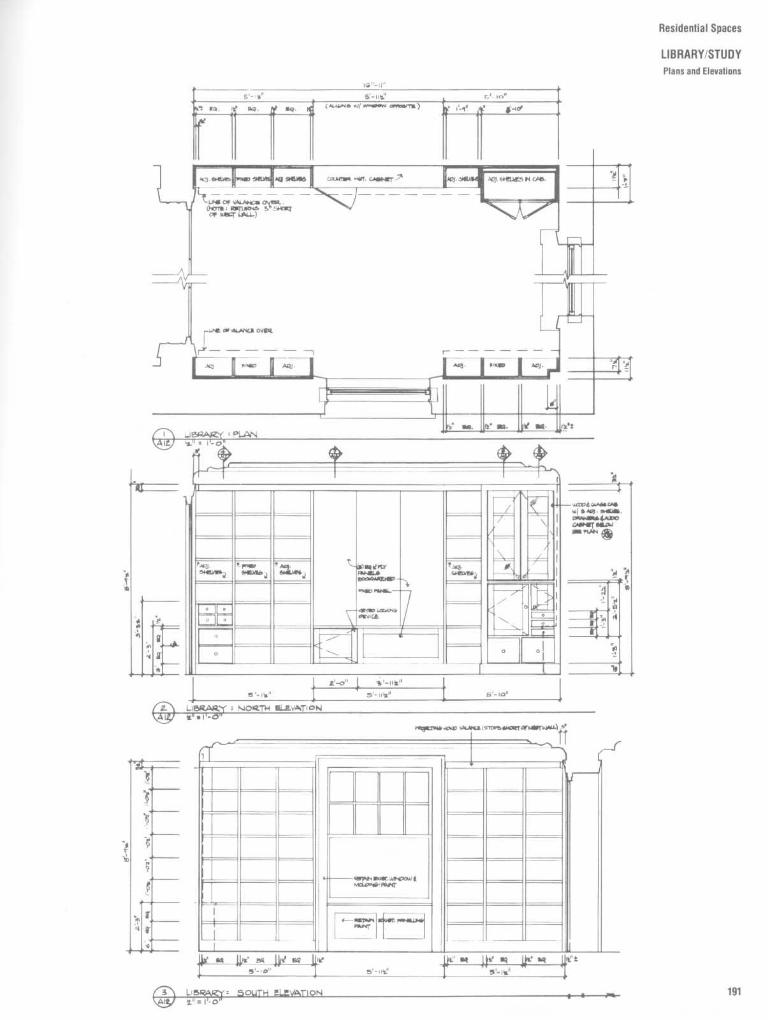
Residential Spaces
LIBRARY/STUDYPlans and Elevations
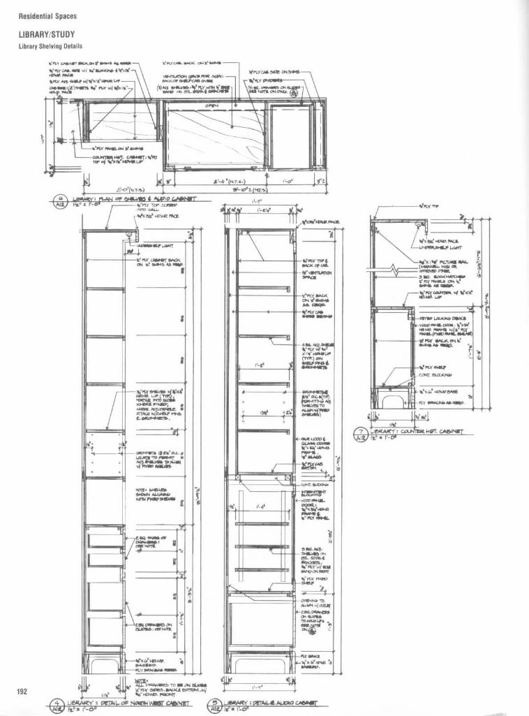
Residential Spaces
LIBRARY/STUDYLibrary Shelving Details

Residential Spaces
LIBRARY/STUDY
Library Shelving Details

Residential Spaces
LIBRARY/STUDY
Built-In Bookshelves
BUILT-IN BOOKSHELVESHere is a simple method of building in bookshelves, bar units, etc ., for residences and other types of buildings by using an egg-cratesystem . The front of the shelf is supported by the vertical members and the back of the shelf is nailed to the plywood back . Thesebuilt-in bookshelves and bar unit were developed for a residence on the Eastern Shore of Maryland . In this design Hugh NewellJacobsen, FAIA, divided the built-in bookcases into units of three shelf widths and introduced a recessed vertical divider 3" deepby 7'/z" wide between bookcase units . The major trim piece is solid wood 1'/e ° X 1'/e ° with a '/a ° wide by '/s" deep groove at themiddle . This simple trim piece acts as framing for sides, top, and bottom of the bookshelves and also for the bar unit with glassshelves and mirrored back, sides, top, and bottom,

Residential Spaces
LIPHARYISTUDY

Residential Spaces
FAMILY/RECREATION ROOMS
Arrangements and Clearances
Recreational Activities
Indoor recreational activities invariably re-quire definite spaces for equipment andclearances for using it . Not all games occupyfloor areas indicated as necessary for thosediagramed on this page . But if interiors areplanned to accommodate large units ofequipment such as that required for tabletennis, and provide necessary playing clear-ances, spaces will be adequate for manyother uses as well .Dimensions of game equipment and floor
areas required for its use are both subject tovariation . Sizes noted here are comfortableaverages, not absolute minima .

Residential Spaces
FAMILY/RECREATION ROOMS
Arrangements and Clearances
TABLE 1
Pool and Billiard Table Sizes (in feet)Size
3x63'/2 x 74x8
4112 x95 x 106 x 12
Where usedHomeHomeHomeCommercial standard in South America, Mexico, and SpainPopular U.S . commercial standardU S. professional standardCommercial standard in Canada and England
Standard ping pong table sizes are 3 ft x6ft;3ft6inx7ft0in;4ft0inx8ft0in ;4ft8inx8ft6in,5ft0inx9ft2in;5ft6inx10ft2in,6ft8inx12ft8in .
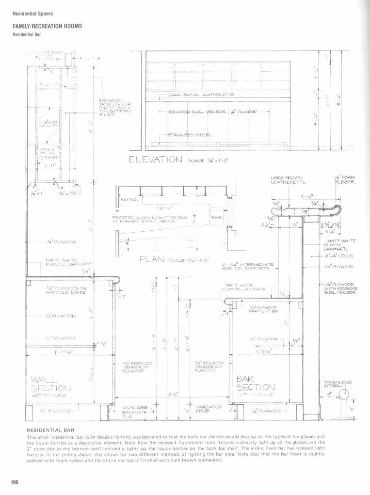
Residential Spaces
FAMILY/RECREATION ROOMSResidential Bar
RESIDENTIAL BARThis small residential bar with double lighting was designed so that the back bar shelves would display all the types of bar glasses andthe liquor bottles as a decorative element . Note how the recessed fluorescent tube fixtures indirectly light up all the glasses and the2" open slot in the bottom shelf indirectly lights up the liquor bottles on the back bar shelf . The entire front bar has recessed lightfixtures in the ceiling above ; this allows for two different methods of lighting the bar area . Note also that the bar front is slightlypadded with foam rubber and the entire bar top is finished with dark brown leatherette .

Residential Spaces
FAMILY/RECREATION ROOMSPiano Sizes ; BarDetails

Residential Spaces
LAUNDRY/SEWING ROOMSLaundry Room Layouts
HOME LAUNDRY ACTIVITIES
Home laundry includes the processes fromsorting through ironing of clothes and house-hold linens, including pretreating, washing,drying, and sprinkling .
General Planning Suggestions
1 . It is desirable to plan space for specificlaundry processes.
2 . Moistureproof surfaces are needed forpretreating and sprinkling of clothes.3. Drying areas should be accessible for
use under all climatic conditions .4. To control moisture in the room, dryers
should be located to permit venting to theoutside of the house.5. Adequate storage for washing equip-
ment and supplies should be located near theplace of first use.6. Facilities for hanging drip-dry garments
after washing should be provided .7. In locating the washing equipment con-
sideration should be given to convenience ofinter-related household activities, distancesfrom the source of soiled clothes and thedrying areas, and the isolation of clutter.
TABLE 1
Space Requirements for Washer-Dryer Arrangements
Type and size of equipment Auxiliary equipment
Basket, 19-inStacked arrangement : washer,31 x 26 in ; dryer, 31 x 26 in
diameterBasket, 19-inAngle arrangement : washer
26 x 26 in ; dryer, 31 x 26 in
diameterBasket, 19-inStraight-line arrangement:
washer, 26 x 26 in ; dryer,
diameter31 x 26 in
Work
Total floor area, in
area, in
Width
Depth
43 x 37
43
63
36 x 59
62
76
36 x 66
62
66
Figures 1 and 2 illustrate arrangements oflaundry equipment. Space needed by a sin-gle worker in front of equipment or betweenequipment placed opposite is indicated .Overall dimensions of areas will vary withtype and size of equipment selected . Noallowance has been made between the backof equipment and the wall for electrical,plumbing, and dryer vent connections. Thespace required will depend on the type ofinstallation used .Counter space is provided for sorting and
folding three washer loads of clothes. The
space under the counters has been used forbins, one for soiled clothing and the other fordry, clean articles that require further treat-ment before use or storage. Additional coun-ter space can be provided by the tops of thedryer and washer, depending upon the typeselected .A tall storage cabinet for laundry supplies
would complement each arrangement. Inthis cabinet, an ironing board, iron, mops, andbuckets (needed for cleaning the laundryarea) may also be stored .

Residential Spaces
LAUNDRY/SEWING ROOMSLaundry Room Layouts
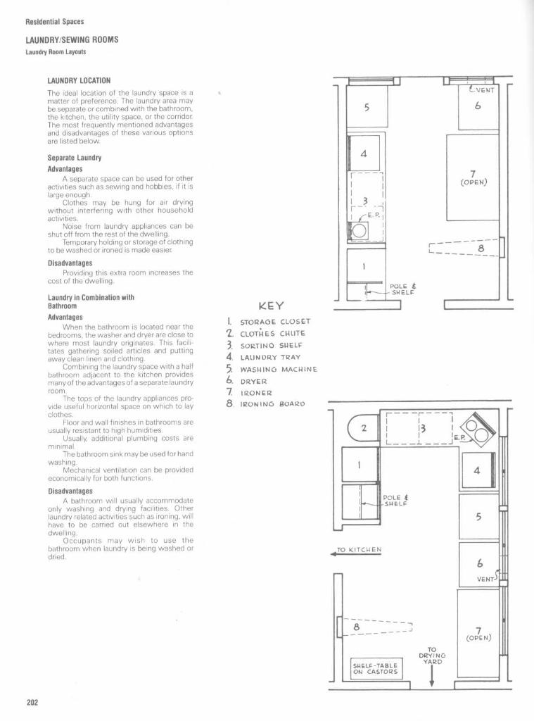
Residential Spaces
LAUNDRY/SEWING ROOMSLaundry Room Layouts
LAUNDRY LOCATION
The ideal location of the laundry space is amatter of preference . The laundry area maybe separate or combined with the bathroom,the kitchen, the utility space, or the corridor.The most frequently mentioned advantagesand disadvantages of these various optionsare listed below.
Separate Laundry
AdvantagesAseparate space can be used for other
activities such as sewing and hobbies, if it islarge enough .
Clothes may be hung for air dryingwithout interfering with other householdactivities .
Noise from laundry appliances can beshut off from the rest of the dwelling .
Temporary holding or storage of clothingto be washed or ironed is made easier.
DisadvantagesProviding this extra room increases the
cost of the dwelling .
Laundry in Combination withBathroom
AdvantagesWhen the bathroom is located near the
bedrooms, the washer and dryer are close towhere most laundry originates . This facilitates gathering soiled articles and puttingaway clean linen and clothing .
Combining the laundry space with a halfbathroom adjacent to the kitchen providesmany of the advantages of a separate laundryroom .
The tops of the laundry appliances pro-vide useful horizontal space on which to layclothes.
Floor and wall finishes in bathrooms areusually resistant to high humidities .
Usually, additional plumbing costs areminimal.
The bathroom sink may be used for handwashing.
Mechanical ventilation can be providedeconomically for both functions.
DisadvantagesA bathroom will usually accommodate
only washing and drying facilities . Otherlaundry related activities such as ironing, willhave to be carried out elsewhere in thedwelling .
Occupants may wish to use thebathroom when laundry is being washed ordried .
KEY
I, STORAGE CLOSET
Z. CLOTHES CHUTE
3, SORTING SHELF
4. LAUNDRY TRAY
WASHING MACHINE
6. DRYER
7 1IZONPR
S. IRONING BUAI20

Residential Spaces
LAUNDRY/SEWING ROOMSLaundry Room Layouts
Laundry in Combination with Kitchen
AdvantagesSuitable in housing for young families
because the person doing the laundry cankeep an eye on the washing machine whiledoing otherjobs and supervising the children .
Direct access to the outside for clothesdrying is likely to be easier than from laun-dries located in a basement or on a secondstorey.
Kitchen sinks are usually sizeable andcan be used for laundering .
Additional plumbing costs are usuallysmall .
DisadvantagesDanger of cross-contamination through
the handling of dirty washing during foodpreparation .
Grease and cooking smells can bepassed on to clean clothes.
Noise generated by running appliancescannot easily be shut off from the rest of thedwelling .
Laundry in Combination with UtilitySpace in Basement
AdvantagesGenerally, as much space as needed can
be provided .Noise generated by running appliances
can be easily shut off from the rest of thedwelling .
DisadvantagesLaundry must be carried up and down
stairs, although automatic dryers have easedthe problem of carrying heavy baskets ofdamp clothes to outdoor clotheslines .
Laundry in Combination withCorridor
AdvantagesThe space is used more economically
(Fig . 9) .The space above the appliances may be
used as a linen closet .The appliances can be hidden from sight
when they are not in use; they can berecessed into the wall and enclosed withdoors.
DisadvantagesNoise generated by running appliances
cannot be easily shut off from the rest of thedwelling .
An alcove adjacent to a corridor willaccommodate only a minimum-sized laundryarea . Other laundry related activities, such asironing, will have to be carried out elsewherein the dwelling .

Residential Spaces
LAUNDRY/SEWING ROOMS
Laundry Room Layouts
Planning for Efficiency
The sequence of laundering operations de-termines the planning of space and facilitiesand the placing of equipment. Convenienceand time-and-step saving are easily achievedby placing the elements in their natural orderof use : (t) clothes chute (with or withoutbins or hampers), (2) sorting table or coun-ter, (3) washing machine, (4) laundry trays,(5) dryer, (6) ironer or mangle, (7) ironingboard, (8) rack, "horse," or table for finishedlaundry In addition, storage closet or cab-inets will be necessary for soaps, powders,bluing, bleaches, starch, basket, clothespins,iron, etc.
KEY
I . STORAGE CLOSET
Z . CLOTHES CNLITE
3. SORTING SPELL=
4.
LAUNDRY TRAYWASHING MACHINE
6. DRYER
7 IRoNc-R
S. IRONING BOARD

General Planning Suggestions
1 . An area especially planned for sewing,convenient to other activity areas, isdesirable.
2. Most houses need storage space forsewing materials and equipment . Theamount and kind of storage required variesaccording to the quality and frequency ofsewing .
3. Aminimum sewing area should includethe machine, auxiliary work surfaces, a chairthat permits freedom of motion, and storagearrangements . The work surface for layoutand cutting may be outside the area forsewing machine operations and serve multi-ple purposes .4. Consideration should be given to work
surfaces at comfortable heights for the vary-ing activities of sewing .5. Light should be adequate for the
activity.
Residential Spaces
LAUNDRY/SEWING ROOMS
Sewing Center Clearances
TABLE 2
Dimensions of Area for Layout and Cutting Garments
Measurement
Working surfaceLengthWidth
Table, free-standingTable obstructed on one side
HeightClearance for worker
TABLE 3
Dimensions of Fitting Space
Use of SpaceViewing in mirror :
Mirror dimensions, inWidthLengthTop to floor
Clearance in front of mirror, ftWidthLength
Clearance while fitting self, ftClearance while being fitted, ft
Fitting garment on dress form, ft
Minimum
56
2828
34-40 (range)18
Minimum
164270
36-86x4
8'/2 x 45x4
Dimensions, inAdequate
72
3632
36 (median)24
Adequate
186072
410
7x6

Residential Spaces
CLOSETS/STORAGE AREAS
Figures 1 and 2 show the vertical clear-ances related to male and female closet andstorage facilities . Wherever possible or prac-tical, the closetshelf should be located withinhuman reach . The height shown for the highshelf has been established based on fifthpercentile male and female data in order toplace it within reach of individuals of smallerbody size . Any shelf located at a greaterdistance should be used primarily for storagethat requires only infrequent access . Thelocation of the shelf just above the rod isessentially a function of rod height . Theclearance between the bottom of the shelfand the top of the rod should allow for easyremoval of the hanger.
Figure 3 illustrates two various types ofwalk-in storage facilities . Undoubtably, it canbe argued that the 36-in, or 91 .4-cm, clear-ance shown between the hanging garmentand the storage shelf or between oppositegarments could be reduced about 50 per-cent . The authors contend, however, that inorder to achieve any degree of comfort in theselection and removal of the desired gar-ment, a minimum of 36 in should be main-tained . The degree to which this dimensioncan be reduced is a question of the level ofcomfort the user is prepared to tolerate inexchange for the floor space saved. The twodrawings of the plan view of the humanfigure illustrate clearances required for don-ning a coat or putting on a pair of stockings.
in cm
64-68 162.6-172 .7
72-76 182.9-193 .0
C 12-18 30.5-45.7
p 8-10 20.3-25.4
20-28 50.8-71 .1
34-36 86.4-91 .4
10-12 25.4-30.5
60-70 152.4-177.8
1 69-72 175.3-182.9
J 76
193.0
68
172.7
L 42
106.7
M 46 116.8
N 30 76 .2
0 18
45 .7

Residential Spaces
CLOSETS/STORAGE AREASTypes of Closets
CLOTHES CLOSETS
The capacity of a clothes closet dependsupon the accessible length of rod. Threetypes of closets are common .
Reach-in closet
The minimum front-to-backdepth of space for hanging clothes is 24". Theaccessible rod length is equal to the width ofthe door opening plus 6" on each side .
Walk-in closet This type provides rods onone or both sides of an access path at least20" wide . A wider access space within thecloset maybe used as a dressing area .
Recommended heights of rods are 68" forlong robes, 63" for adult clothing, and 32" forchildren's clothing .
Shelf Space and LightingThe shelf is normally located 2" above therod, and another shelf may be located 12"higher. Shelves higher than the rod mayalsobe installed at the end of the closet .A fluorescent fixture over the door is
recommended for lighting a closet . Deluxecool white tubes match daylight for selectingclothes.
Rod Lengths and HeightsThe Minimum Property Standards of HUD(1973) require that each bedroom have acloset, with rod and shelf, with minimumdimensions of
For double-occupancy bedrooms :24" by 60"
For single-occupancy bedrooms :24" by 36"
For closet at entrance to house :24" by 24"
A more desirable front-to-back depth wouldbe 28" for bedroom closets and 30" forentrance closets to accommodate bulkyouter garments .The average rod space per garment is
about 2" for women's clothing, 21/4" for men'sclothing, and 4" for heavy coats.
Edge-in closet By providing an edge-inspace of at least 18", the accessible rodlength can be much longer than the doorwidth. This requires less wall space than a fullfront opening.

Residential Spaces
CLOSETS/STORAGE AREASClothes Closet Details
Fig . 4
Bedroom closet designed for one person .This diagram shows dimensions for rods, shelves,and drawers to hold underwear, sweaters, shoes,hats, purses, and ties . Research shows that eachperson needs at least 48 inches of rod space forhanging clothing .

Residential Spaces
CLOSETS/STORAGE AREASClothes Closet Details

Residential Spaces
CLOSETS/STORAGE AREAS
Clothes Closet Details

Residential Spaces
CLOSETS/STORAGE AREASClothes Closet Details

Residential Spaces
CLOSETS/STORAGE AREAS
Clothes Closet Details

Residential Spaces
CLOSETS/STORAGE AREASCloset Wall Details
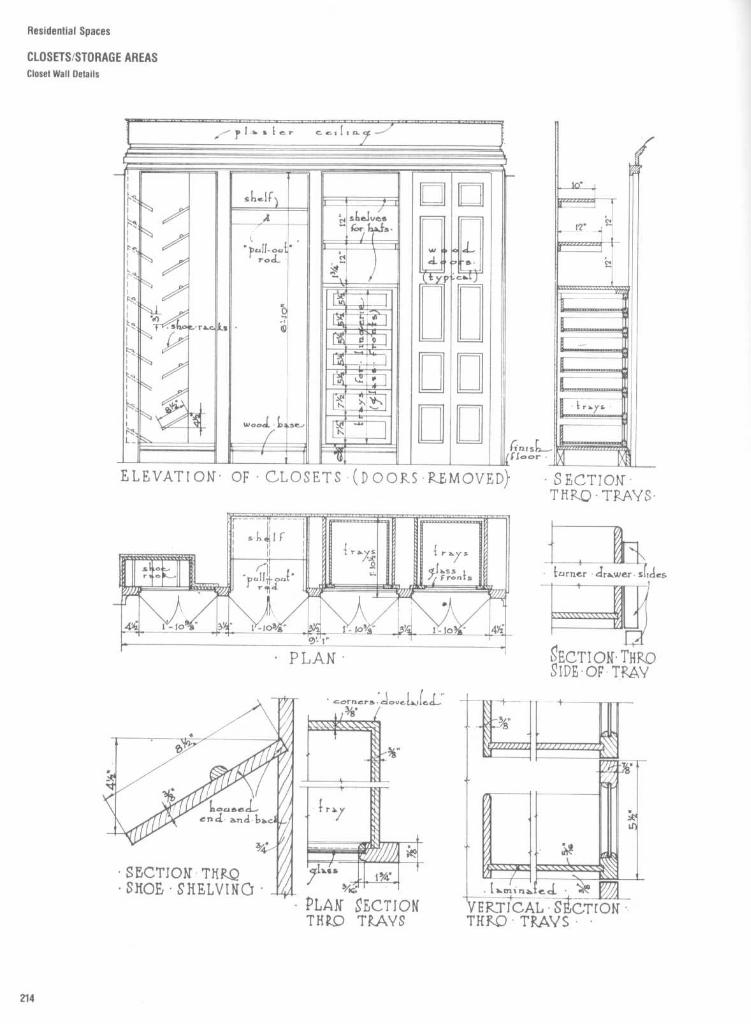
Residential Spaces
CLOSETS/STORAGE AREASCloset Wall Details

Residential Spaces
CLOSETS/STORAGE AREASGeneral Storage Shelving
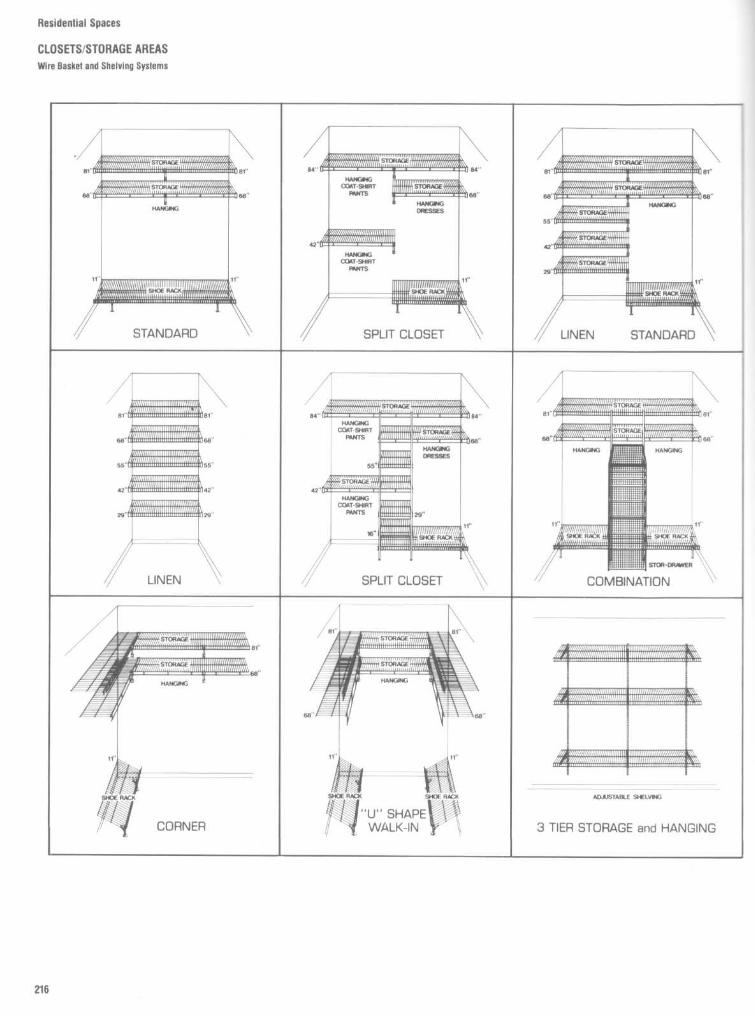
Residential Spaces
CLOSETS/STORAGE AREASWire Basket and Shelving Systems

Residential Spaces
CLOSETS/STORAGE AREASWire Basket and Shelving Systems
Front ViewMultiple-stacked,wrap-around storageshelving . Optionalbaskets and doorracks. (%'12; 16" and20 widths available)
Top ViewAll the shelving you'llever need for full-sizefamily food storage.Sliding baskets holdfruit, vegetables andother kitchen supplies .Optional door racksmaximize storagearea by utilizing allavailable space.
Front View_Multiple-stackedstorage shelving .Optional full-heightdoor storage rack .(9 ; 12; 16° and 20'widths available)
Top ViewStandard pantrydesign providesample shelving andstorage for cannedgoods and other fooditems. Center polegives extra support.Optional door racksprovide easy accessto your mostneeded items.
Front ViewDouble, full-widthstorage shelving withside-mounted shelv-ing and basket unitand optional door/wallstorage rack . (12,16widths available)
Top ViewMake a clean sweepof cleaning with full-length shelves thathold a variety of uten-sils . Storage basketspack brushes, clothsand sundry items.Bottled detergentsand cleaning productscan be stored neatlyand safely in optionaldoor racks.
Front ViewDouble, full-widthupper storage shelv-ing with stackedstorage shelving . (12,'16 widths available)
Tbp-ViewMakes houseworkeasier to handle bystoring householdcleaning items justwhere you need them .Plenty of shelvingspace for cloths,detergents andbrushes. Wide storagearea holds vacuumcleaner, brooms, mopsand small appliances .
HOUSEKEEPING/UTILITY ROOM

Residential Spaces
CLOSETS/STORAGE AREAS
Wire Basket and Shelving Systems
BEDROOMAPPLICATIONSFront ViewSingleand doublehang with upperstorage, center polesupport and shoeracks. (12; 16" widthsavailable)
Top ViewCombination con-venience for singleand double hangingclothes. The perfecthis and hers closet .Extra wide shelfspace for clothing,linen and blankets inyour master bedroom.Plus lots of room forher long dresses andcoats-his shirts,suits and slacks . Shoeracks on both sides.
Front ViewWalk-In. Single anddouble hang withupper storage andcentral shelvingunit with additionalclearance and shoeracks. (12; 16 widthsavailable)Top ViewSingle hanging spacefor coats and otherlong garments .Double hangingconvenience forshorter garments .Full shelves withcentral storage unitallow easy storageof sweaters, boots,sports equipment,tall and over-sizeditems. Tailor-madefor couples witha 2nd bedroom.
Front ViewStandard .Doublehang with shoe rackand off-center polesupport. (12; 16"widths available)
Top ViewMakes kids stuff outof chaos in any teen-ager's room . Plentyof storage spacefor footballs, beachequipment, basket-balls, skates andother cumbersomeitems. Doubles asstorage area fordresses and coats.Conveniently placedhanging rod for allyour teenager'sclothing .
Front ViewFull-width, doublehanging with lowershelving height . Slid-ing basket systemand shoe racks. (12;16 widths available)ToR ViewSpecially designedfor the children'sroom . Extra low-hanging shelf makesit easy for kids toreach. Stores toys andsports equipment ineasy-access slidingbaskets . Shoe rackkeeps sneakers andother footwear neatlyorganized.

Residential Spaces
CLOSETS/STORAGE AREAS
Wire Basket and Shelving Systems
Front View
__Multiple-stackedlinen shelving .(%'12' . 16 and 20widths available)
Top ViewBathroom linen closetstores towels, sheetsand cleaning suppliesin one easy-access area .
Front ViewMultiple-stackedlinen shelving withpole support and slid-ing basket system .M'14 16 and 20"widths available)
Top ViewFour extra-wideshelves for linen andblankets . Storagebaskets slide out andhold dish cloths, pil-lowcases and smalleritems. The perfectlinen closet.
FOYER/FRONT ENTRY CLOSETFront ViewSingle hang withupper storage and off-center storage unitand shoe racks. (12;16 widths available)
Top ViewAwelcome additionto anyhome . Full-width, upper storageholds hats, gloves andsweaters . Off-centerstorage for umbrellasand winter items.Shelves, shoe racksand generous hang-ing space lets guestsknow they're welcome.
Front ViewSingle hang with half-length shoe racks andupper storage. (12 ; 16widths available)
Top ViewHolds coats, hats,shoes and guestclothing with care .Upper storage areafor visitor's bagsand small cases.
LINEN

Residential Spaces
CLOSETS/STORAGE AREASWire Basket and Shelving Systems
MASTER BEDROOMS
Front ViewWalk-In. Single hangwith upper storageand central shelving/basket unit and shoeracks. (1416" widthsavailable)
TopViewKeeps shoes, shirtsand clothing neatlyorganized. Slidingbaskets for easyaccess to linen,underwear, etc. Full-length clothes storagefor dresses, shirtsand suits . Ideal formaster bedroom.
Front ViewSingle hang withupper storage andcentral shelving andbasket unit, addi-tional clearance andshoe racks. (12', 16"widths available)
~op ViewSo well designed itactually replaces apiece of furniture!Four sliding basketsprovide multiplestorage capacity forshirts, underwear,socks and sweaters .Full-length clotheshanging space, full-width shoe racks andlots of shelf spacemake this systema must for your2nd bedroom.
Front ViewWalk-In. Singleanddouble hang withupper storage, centralshelving and shoeracks. (12; 16" widthsavailable)
Top ViewHang dresses andcoats on one side,suits and shorter gar-ments on the other.Central shelvingactually replaces apiece of furniture inthe master bedroom!
Front ViewSingle hang withupper storage andfull-width shoeracks. (12',16" widthsavailable)
Top_ViewDoubles shelf/storagespace. Single hangingfor clothes, coats,shirts and jackets.Expands easily toaccommodate futureneeds. 'Mro full-length shoe racks.

Office SpacesGeneral offices and multiple workstations
223Private offices
231Electronic workstations
241Conference rooms
249Reception areas
260Furniture, furnishings, and equipment
278

Office Spaces
INTRODUCTION
The amount of office space built during the past few decades can bemeasured in the hundreds of billions of square feet . Within these buildings,workers spend nearly half their waking hours and a third of their entire lives .Over the life span of a typical office building, the same spaces may be
occupied by a succession of different tenants, each with their own program-matic requirements . Consequently, interior spaces may be recycled andredesigned many times, simply to accommodate the changing needs of newcorporate users . In many instances redesign may be necessitated solely bythe effect of technological change on the methodology of transactingbusiness . Moreover, the escalating costs of land acquisition and constructionand the increasing scarcity of urban building sites make it essential that theredesign reflects an efficient, cost-effective utilization of space, as well as onethat is responsive to the human factors involved . It is necessary, therefore, forthe designer to be familiar not only with the general planning criteriaassociated with office design, but with the architectural detailing of some ofthe typical interior elements contained within these spaces .
Accordingly, this section includes general planning criteria and examples ofactual working drawings of typical interior conditions, prepared by variousdesign professionals. The details alluded to include such items as tradingdesks, elevated computer floors, library furniture, built-in storage cabinets,work counters, wall paneling, vanities, reception desks, and conference roomelements . Also included are illustrations and dimensional data pertaining totypical office furniture, equipment, and electronic media storage.

Office Spaces
GENERAL OFFICES AND MULTIPLE WORKSTATIONSPlanning Data : Basic Workstations
The so-called general office takes on avariety of forms and configurations . In itssimplest variation it may be nothing morecomplex than several standard desks withreturns located within a room or space . In itsmore sophisticated and ergonomically de-signed form, the general office may be basedon an open planning or office landscapingconcept, involving a system of workstations .The workstations include desk surfaces,files, acoustic partitions, and a host of otheroptional components to suit the nature of theparticular work tasks involved . The systemsare extremely flexible, allowing the worksta-tions to be configured in a variety of shapes .Provision for power and lighting is quitecommon .The design of the general office, like the
design of the private office, requires a knowl-edge of the basic dimensional requirementsand clearances of the workstation and,where applicable, of the visitor seating to beaccommodated .
In certain instances, where customizedand/or built-in storage elements, work coun-
ters, credenzas, etc ., are required, a knowl-edge of architectural woodworking, as maybe related to the design of such elements,can be quite helpful .
Accordingly, this part includes basic plan-ning criteria for general office design, inaddition to examples of architectural wood-work details in connection with some of themore common customized components ofgeneral office spaces .The basic workstation, as illustrated in plan
in Fig . 1, is the fundamental building block inunderstanding the anthropometric consid-erations for the planning and design of thegeneral office . The worktask zone must belarge enough to accommodate the paper-work, equipment, and other accessories thatsupport the user's function . The work/activityzone dimension, shown in Fig . 1, is estab-lished by the space requirements needed foruse of the typical return . In no case shouldthis distance be less than the 30 in, or 76 .2cm, needed to provide adequate space forthe chair clearance zone . The visitor seatingzone, ranging in depth from 30 to 42 in, or
76 .2 to 106 .7 cm, requires the designer toaccommodate both the buttock-knee andbuttock-toe length body dimensions of thelarger user If an overhang is provided or thedesk's modesty panel is recessed, the visitorseating zone can be reduced due to theadditional knee and toe clearances provided .The specific type and size of the seating (i .e .,if it swivels or if it has casters) also influencethese dimensions .
Figure 2 shows the typical workstationexpanded into the basic U-shaped configura-tion . The work/activity zone dimension rangeis shown as 46 to 58 in, or 116 .8 to 147 .3 cm ;additional space is needed to allow fordrawer extension of the lateral file . Not onlydoes it provide more storage, the lateral fileunit is generally the same height as that ofthe worksurface and is often utilized as asupplementary worksurface . The distancebetween this unit and that of the primaryworksurface must be sufficient to allow formovement and rotation of the chair.

Office Spaces
GENERAL OFFICES AND MULTIPLE WORKSTATIONS
Planning Data : Basic Workstations
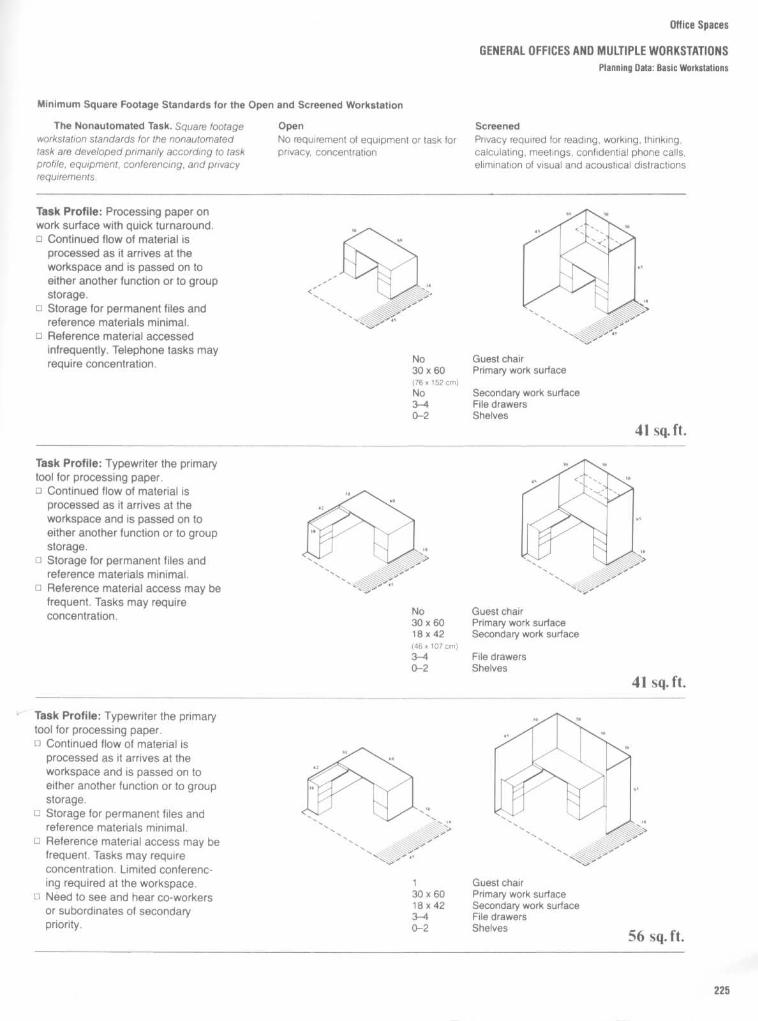
Office Spaces
GENERAL OFFICES AND MULTIPLE WORKSTATIONSPlanning Data : Basic Workstations
Minimum Square Footage Standards for the Open and Screened Workstation
The Nonautomated Task . Square footageworkstation standards for the nonautomatedtask are developed primarily according to taskprofile, equipment, conferencing, and privacyrequirements .
OpenNo requirement of equipment or task forprivacy, concentration
ScreenedPrivacy required for reading, working, thinking,calculating, meetings, confidential phone calls,elimination of visual and acoustical distractions
Task Profile : Processing paper onwork surface with quick turnaround .o Continued flow of material is
processed as it arrives at theworkspace and is passed on toeither another function or to groupstorage .
o Storage for permanent files andreference materials minimal .
o Reference material accessedinfrequently . Telephone tasks mayrequire concentration .
Task Profile : Typewriter the primarytool for processing paper .o Continued flow of material is
processed as it arrives at theworkspace and is passed on toeither another function or to groupstorage .
o Storage for permanent files andreference materials minimal .
o Reference material access may befrequent . Tasks may requireconcentration .
Task Profile : Typewriter the primarytool for processing paper .o Continued flow of material is
processed as it arrives at theworkspace and is passed on toeither another function or to groupstorage .Storage for permanent files andreference materials minimal .
o Reference material access may befrequent . Tasks may requireconcentration . Limited conferenc-ing required at the workspace .
o Need to see and hear co-workersor subordinates of secondarypriority .
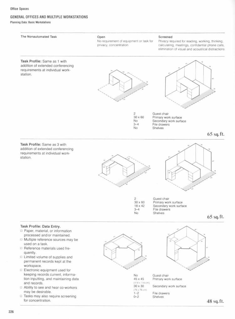
Office Spaces
GENERAL OFFICES AND MULTIPLE WORKSTATIONSPlanning Data : Basic Workstations
The Nonautomated Task OpenNo requirement of equipment or task forprivacy, concentration
ScreenedPrivacy required for reading, working, thinking,calculating, meetings, confidential phone calls,elimination of visual and acoustical distractions
Task Profile : Same as 1 withaddition of extended conferencingrequirements at individual work-station .
Task Profile : Same as 3 withaddition of extended conferencingrequirements at individual work-station .
Task Profile : Data Entry.o Paper, material, or information
processed and/or maintained .o Multiple reference sources may be
used on a task .c Reference materials used fre-
quently .o Limited volume of supplies andpermanent records kept at theworkspace .
u Electronic equipment used forkeeping records current, informa-tion inputting, and maintaining dataand records .
u Ability to see and hear co-workersmay be desirable .
o Tasks may also require screeningfor concentration .

Office Spaces
GENERAL OFFICES AND MULTIPLE WORKSTATIONSPlanning Data : Multiple Workstations
Fig . 3
Depending upon function, the sizes of individual and multiple workstations vary dramatically. Size of worksurface, length and depth of return, chair
size, and circulation patterns all influence the gross square footage requirements .

Office Spaces
GENERAL OFFICES AND MULTIPLE WORKSTATIONSPlanning Data : Multiple Workstations
Fig . 4
Floating or free-standing workstations tend to utilize more floor area than workstations placed against a wall or sharing the same wall panel .Clustering of workstations will ultimately result in the use of less floor area, but at the expense of majorergonomic considerations . Decisions relativeto both acoustical privacy and personal space are often sacrificed in the name of economy.

Multiple workstations can result in effi-cient utilization of space and sharing ofexpensive computer terminals and equip-ment . If use of computer terminals is inten-sive, individual CRTs should be provided .Figures 5, 6, and 7 each show eight worksta-tions, yet the setups range in area from 448to 1012 ft 2 . Furniture size, function, andergonomic considerations all affect setup.
Office Spaces
GENERAL OFFICES AND MULTIPLE WORKSTATIONS
Planning Data : Multiple Workstations

Office Spaces
GENERAL OFFICES AND MULTIPLE WORKSTATIONSPlanning Data : Office Layout
It is not unusual to have two or morepersons share an enclosed office space. Inplanning this type of office space, bothcirculation and clearance become criticallyimportant . Door swings, the extension of filedrawers, and points of entry must all becarefully considered .

The design of the private office requires aKnowledge of the basic dimensional require-ments and clearances of the executive work-station and, where applicable, of visitor seat-ing accommodations . In certain instanceswhere various aspects of the office interiorare customized and/or built into the construc-tion, a knowledge of architectural woodworkdetailing is also desirable.This page and the following pages include
the necessary planning criteria required, aswell as details of certain customizedcomponents .
Executive workstation and/or desk sizeand configuration can be customized de-pending on desired image, scale, and am-bience . Desks are also available in generallyaccepted standard sizes. It is these standarddesks that are most used in the design of theprivate office . Figure 1 illustrates the range ofdesk dimensions, chair dimensions, andclearances involved .Many private executive offices are being
designed with desks that do not conform
A_B_CD_EF_G_H
K_LM_N
_PQ
S
in
30-39
Cm
76.2-99.166-84 167.6-213.421-28 53 .3-71 .124-28 61 .0-71 .123-29 58 .4-73.742 min . 106.7 min .105-130 266.7-330.230-45 76.2-114.333-43 83 .8-109 .210-14 25.4-35 .66-16 15.2-40 .620-26 50.8-66 .012-15 30.5-38.1
117--148 297.2-375.945-61 114.3-154.930-45 76.2-114 .312-18 30.5-45.729-30 73 .7-76 .222- 32 55.9-81 .3
Office Spaces
PRIVATE OFFICESExecutive Workstation
with the basic rectangular shape. Such asituation is illustrated in Fig. 2, which shows acircular executive desk . Such a desk is oftenselected if the executive in question plans tohold conferences within the office and pre-fers the psychology of having either visitorsor employees gather around the worksurfacein an egalitarian fashion. While a minimumdesk size of 48 in, or 121 .9 cm, is shown, thisdimension is also influenced by the numberof side chairs to be grouped around the desk .A circular executive desk must be sup-
ported by supplementary credenza or filestorage within easy reach of the executivechair. Side arm reach relative to the work/activity zone must always be studiedcarefully.
Figure 3 illustrates a typical circular loungegrouping found within an executive office .Providing for the appropriate leg clearance of12 to 18 in, or 30 .5 to 45 .7 cm, is alsodetermined by the sitting zone requirements .Buttock-knee length must also beconsidered .

Office Spaces
PRIVATE OFFICESExecutive Workstation
A
in
77-8830
C 46-58
Cm
195.6-223.576.2
116.8-147.3p 22-28 55.9-71 .1
24-30 61 .0-91 .424-28 61 .0-71 .12-3 5.1-7.620-22 50 .8-55.948-60 121 .9-152 .4
J 92-116 233 .7-294.6K 36-42 91 .4-106.7L 6-9 15.2-22.9
24
61 .042-60 106.7-152.436-48 91 .4-121 .957-78 144.8-198 .133-43 83.8-121 .912-18 30 .5-45 .721-30 53 .3-76 .224-32 61 .0-81 .3

Office Spaces
PRIVATE OFFICESPlanning Data : Typical Room Arrangements

office Spaces
PRIVATE OFFICES
Planning Data : Typical Room Arrangements
The private offices illustrated in Figs . 12 to17 reflect middle to senior managementfunctional, as well as status, requirements .Each office layout should be carefully re-viewed with the client to ensure that allprogrammatic functions have been met . Of-fices of this size do not easily accommodatean independent conference function .

Office Spaces
PRIVATE OFFICESPlanning Data : Typical Room Arrangements

Office Spaces
PRIVATE OFFICES
Wall Unit Details
Fig . 21
Custom architectural woodwork, or "built-ins ;' is often required for executive offices . These architectural working drawings reflect the custom design of
a storage wall for a partner in a law office . Careful analysis shows the incorporation of file, book, and coat storage within a floor-to-ceiling mahogany wood unit .

Fig . 22
These details represent typical vertical sec-tions taken through various storage components for thepartner wall unit shown in Fig . 21 . Careful attentionmust be given to integration of electronic equipment,electrical wiring, and task lighting .
Office Spaces
PRIVATE OFFICES
Wall Unit Details

Office Spaces
PRIVATE OFFICES
Wall Unit Details
Fig . 23
In many instances, the utilization of standard wood moldings can enhance the overall appearance of an otherwise relatively simpleworkwall unit . Other cost-saving devices illustrated here are the application of a wood panel to a standard metal file and the use of a fabric-wrapped tack board . The incorporation of an undercabinet task light is almost always required .

Fig . 24
These plan oblique drawings provide detailed design information to both client and architectural woodwork contractor. Thesedrawings are particularly helpful when the office project for which these wall units are intended consists of many offices, andeach officeis to be customized within certain constraints .
Office Spaces
PRIVATE OFFICESWall Unit Details

Oftice Spaces
PRIVATE OFFICES
Credenzas
Many private offices require the detailingof custom credenzas and storage units. Thesophistication and complexity of such detailscan significantly influence the budget for thespace as well as the time of installation .Figure 25 represents a "high-end" approach,while Fig. 26 is more appropriate for officeswith a moderate budget .

Office Spaces
ELECTRONIC WORKSTATIONS
Planning Data : Anthropometrics
New electronic technologies, togetherwith the advent and proliferation of themicrocomputer and the availability of inex-pensive packaged software, have changedthe complexion of the office workplace. Theergonomic considerations related to this newwork environment have necessitated a re-evaluation of the traditional interface be-tween the seated office worker and his or herworkplace. It is essential that the design ofthis electronic workstation be responsive tohuman factors in order to avoid physicaldiscomfort for the user. The location of theKeyboard, angle of the visual display terminal,adjustability of the chair, field of vision, provi-sions for back support, and height of the seatabove the floor are a few of the considera-tions in the design process .This page and the following pages provide
a variety of anthropometric and ergonomicplanning data and details for use as referencein the design of the electronic workstation .
Figure 1 illustrates guidelines for use inestablishing preliminary design assumptionsfor a workstation display console. Since thetypes of displays and the nature of the tasksassociated with those displays can vary con-siderably, Fig. 1 cannot be taken too literally.The configuration shown, however, is fairlyrepresentational . Certain basic factorsshould be noted anthropometrically. The useof an adjustable chair will permit the eyeheight of the seated viewer to be raised orlowered to view the display, as may berequired depending on body size . An adjust-ment range between 15 and 18 in, or 38 .1 and45.7 cm, should be adequate to accommo-date the eye height sitting requirements ofabout 90 percent of all viewers. Adjustability,however, will be of little value if the verticaldistance between the underside of the deskand the floor is insufficient to accommodatethe knee height and thigh clearance whenthe seat is adjusted to the appropriate posi-tion . If such distance is not less than 26.5 in,or 67 .3 cm, the majority of viewers will beaccommodated .The location of the top of the display
should align with the standard sight line foroptimum viewing conditions . Since the eyeand the head can rotate within certain limita-tions and, in so doing, increase the area thatcan be scanned, displays can be locatedabove the standard sight line when abso-lutely necessary. It should also be noted thatthe more perpendicular the normal sight lineis to the display plane, the greater theviewing comfort. Accordingly, considerationshould be given to sloping the display planesince the normal sight line is about 15° belowthe horizontal .
Stature is the vertical distance from thefloor to the top of the head, measured whilethe subject stands erect, looking straightahead.
Elbow height is the distance measuredvertically from the floor to the depressionformed at the elbow where the forearmmeets the upper arm.
Eye height is the vertical distance fromthe floor to the inner corner of the eye,measured with the subject looking straightahead and standing erect.
Sitting height erect is the vertical dis-tance from the sitting surface to the top ofthe head with the subject sitting erect.
Sitting height normal is the vertical dis-tance from the sitting surface to the top of
the head, measured with the subject sittingrelaxed.
Eye height is the vertical distance fromthe inner corner of the eye to the sittingsurface.
Shoulder height is the distance takenvertically from the sitting surface to a pointon the shoulder midway between the neckand acromion .
Shoulder breadth is the maximum hori-zontal distance across the deltoid muscles.
Elbow to elbow is the distance acrossthe lateral surfaces of the elbows measuredwith elbows flexed and resting lightly againstthe body with the forearms extendedhorizontally.
Hp breadth is the breadth of the bodyas measured across the widest portion ofthehips . Note that a hip breadth measurementcan also be taken with the subject in astanding position, in which case the defini-tion would be the maximum breadth of thelower torso.
Elbowrestheight istheheightfromthetop of the sitting surface to the bottom of thetip of the elbow.
Thigh clearance is the distance takenvertically from a sitting surface to the top ofthe thigh at the point where the thigh and theabdomen intersect .
Knee height is the vertical distancefrom the floor to the midpoint of the kneecap.
Popliteal height is the distance, takenvertically, from the floor to the underside ofthe portion of the thigh just behind the kneewhile the subject is seated with body erect.The knees and ankles are usually perpen-dicular, with the bottom of the thigh and theback of the knees barely touching the sittingsurface .
Buttock-popliteal length is the horizon-tal distance from the rearmost surface of thebuttock to the back of the lower leg .
Buttock-knee length is the horizontaldistance from the rearmost surface of thebuttocks to the front of the kneecaps .
Buttock-toe length is the horizontal dis-tance from the rearmost surface of thebuttocks to the tip of the toe.
Buttock-heel length is the horizontaldistance from the base of the heel to a wallagainst which the subject sits erect with hisleg maximally extended forward along thesitting surface . This is sometimes referred toas buttock-leg length .
Vertical reach is the height above thesitting surface of the tip of the middle fingerwhen the arm, hand, and fingers are ex-tended vertically.
Vertical grip reach is usually measuredfrom the floor to the top of a bar grasped inthe right hand while the subject stands erectand the hand within which the bar is graspedis raised as high as it can be convenientlywithout experiencing discomfort or strain .
Side arm reach is the distance from thecenter line of the body to the outside surfaceof a bar grasped in the right hand while thesubject stands erect and the arm is conve-niently outstretched horizontally without ex-periencing discomfort or strain .
Thumb tip reach is the distance fromthe wall to the tip of the thumb measuredwith the subject's shoulders against the wall,his arm extended forward, and his indexfinger touching the tip of his thumb.
Maximum body depth is the horizontaldistance between the most anterior point onthe body to the most posterior. Anteriorpoints are usually located on the chest orabdomen while the posterior points are usu-ally found in the buttock or shoulder region .
Maximum body breadth is the max-imum distance, including arms, across thebody.
In
cm
16-18 40.6-45.716 min.
40.6 min.
C
18 min.
45.7 min .p
15-18 adjust .
38.1-45 .726.5 min .
67 .3 min.
F 30
76.2

Office Spaces
ELECTRONIC WORKSTATIONSPlanning Data : Anthropometrics
Both the work surface and the displaymonitors must be lowered and raised as aunit with 31 .8 cm of travel .m The work surface must be tilted any-
where between a horizontal position to 35°below horizontal . The work surface, at itslowest setting and with a 10° tilted angle, asis common in use, must be 63 .5 cm in heightat its front edge .m The work surface must raise to a hori-
zontal height of 104 cm, accommodating amajority of people in a standing position .m The monitor screens must be tiltable to
any position between 15° forward of verticaland 15° back . This lets the user adjust thescreen to avoid reflective glare, and it accom-modates various working positions of differ-ent lines of sight .
Adjustment controls designed for handoperation must be located within the oper-ator's extended reach envelope .m All surfaces must have matte or dull
finishes . This reduces the likelihood of re-flective glare .m The workstation must be compact and
relatively easy to move through a standard81-cm doorway.m No structural components shall exist
which inhibit the workstation's operation byusers in wheelchairs, ensuring a barrier-freeworkstation .w Service personnel must have easy ac-
cess to electrical components .The digitizing surface must accommo-
date standard European and American D sizedrawings,m Screen depth of view must allow alpha-
numeric characters to be viewed at an anglebetween 20 and 28 arc minutes.

Office Spaces
ELECTRONIC WORKSTATIONS
The Automated Task . Square footage
Open
Screenedworkstation standards for the automated task
No requirement of equipment or task for
Privacy required for reading, working, thinking,are also developed primarily according to task
privacy, concentration
calculating, meetings, confidential phone calls,profile , equipment, conferencing, and privacyelimination of visual and acoustical distractions
requirements .
Task Profile: Data Retrieval .- Paper, material, or information processed,
analyzed, and/or maintained .- Multiple reference sources may be used on a
task.- Reference materials used frequently .- Limited volume of supplies and permanent
records kept at the workspace.= Electronic equipment may be used for easy
reference, retrieval, keeping records current,and maintaining data and records.
= Additional equipment such as microfilm viewermay be required .
= Ability to see and hear co-workers may bedesirable .
= Tasks may also require screening for concentration .
Task Profile : Shared Tasks.= Paper, material, or information processed,
analzyed, and/or maintained .= More than one task may be performed concur-
rently .= More than one operator uses same equipment= Multiple reference sources may be used on a
task .Reference materials used may be used fre-quently .
= Electronic equipment may be used for easyreference, inputting/maintaining data andrecords, retrieval, keeping records current .Storage requirements vary according to task .
Task Profile : Administrative Specialist/Secre-tarial .
Paper, material, or information processed,analyzed, and/or maintained .
o More than one task may be performed concur-rently .
o Multiple reference sources may be used on atask .
o Reference materials used frequently .o Electronic equipment may be used for easy
reference, retrieval, keeping records current,inputting/maintaining data and records.
o If supervising, ability to see subordinates maybe desirable to direct activities .
o If monitoring, visual access may be desirable .o Moderate amount of storage required at the
workspace, that is, casework, client accounts,supplies .

Office Spaces
ELECTRONIC WORKSTATIONS
The Automated Task
Open
ScreenedNo requirement of equipment or task for
Privacy required for reading, working, thinking,privacy, concentration
calculating, meetings, confidential phone calls,elimination of visual and acoustical distractions
Task Profile : Administrative Specialist/Secretarial (+Guest) .o Paper, material, or information processed,
analyzed, and/or maintained .o More than one task performed concurrently .o Multiple reference sources used on a task .o Reference materials used frequently .o Limited volume of supplies and permanent
records kept at the workspace .n Electronic equipment may be used for easy
reference, retrieval, keeping records currento Tasks are complex enough to require concentration .o Extensive use of telephone and additional
equipment such as desk-top printer and micro-film viewer may be required .
a Need to see and hear co-workers is secondary priority .o Limited conferencing required at workspace .o If supervising, ability to see subordinates may
be desirable to direct activities.o If monitoring, visual access may be desirable .
Task Profile : Word Processing .o Time divided among administrative, processing
paper, material, or information .o More than one task may be performed concur-
rently .o Multiple reference sources may be used on a
task .o Reference materials moderate but used fre-
quently .o Limited storage primarily for supplies .o Ability to see and hear co-workers or subordi-
nates is desirable .o Typewriter and/or electronic equipment may be
used to expedite processing and administrativetasks, for example, VDT, printer, transcriber,OCR, microfilm viewer, separate disk drives .
Task Profile : Word Processing (+ Guest) .o Time divided among administrative, processing
paper, material, or information, and limitedconferencing at workspace .
o More than one task may be performed concur-rently .
,o Multiple reference sources may be used on atask .
o Reference materials moderate but used fre-quently .
o Limited storage primarily for supplies .o Typewriter and/or electronic equipment (VDT,
printer, and so on) may be used to expediteprocessing and administrative tasks .
Li Tasks are complex enough to require concentra-tion for analysis, or heavy equipment operationsrequire acoustical screening .
11 Work surface needed for organization of work .

Office Spaces
ELECTRONIC WORKSTATIONS
The Automated Task
Open
ScreenedNo requirement of equipment or task for
Privacy required for reading, working, thinking,privacy, concentration
calculating, meetings, confidential phone calls,elimination of visual and acoustical distractions
Task Profile : Technical/Systems Analyst) Programmer.- Time divided among administrative, processing
paper, material, or information, and limitedconferencing at workspace.More than one task may be performed concur-rently .Multiple reference sources may be used on atask .
* Reference materials may be extensive and usedfrequently .
* Ability to see and hear co-workers or subordi-nates desirable .Typewriter and electronic equipment (VDT,printer, and so on) may be used to expediteprocessing and administrative tasks .
o Moderate to extensive amount of storagerequired at the workspace for manuals, binders,computer printouts, coding sheets, supplies,permanent files, reference materials .
Task Profile : Administrative/Managerial .o Extensive conferencing at individual workspace .o Analysis of reports, computerized materials, and
so on .o Varied tasks or projects performed simultane-
ously on an ongoing basis .o Large amounts of storage extensively used .o Storage for client/project files, reference
manuals, documentation, correspondence .o Telephone used extensively .o Supervision of subordinates almost universal .o Electronic equipment accommodation is
secondary priority, used primarily for communi-cation/electronic mail, scheduling .
Task Profile : Administrative/Total Enclosure .o Extensive conferencing at individual workspace .a Analysis of reports, computerized materials, and
so on .o Varied tasks on projects performed simultane-
ously on an ongoing basis .o Large amounts of storage extensively used .o Storage for client/project files, reference
manuals, documentation, correspondence .u Telephone used extensively .o Supervision of subordinates almost universal .o Electronic equipment accommodation is
secondary priority, used primarily for communi-cation/electronic mail, scheduling .
o Subject matter of job responsibilities requiresconfidentiality .

Office Spaces
ELECTRONIC WORKSTATIONS
Trading Desk Details
Fig . 2
Technologically and electronically complex trading desks must be ergonomically correct in every respect . With little, if any, margin for error whendesigning and detailing multiple workstations of this type, a full-size mockup is always required .

Office Spaces
ELECTRONIC WORKSTATIONSTrading Desk Details

Office Spaces
ELECTRONIC WORKSTATIONS
Trading Table Details

Office Spaces
CONFERENCE ROOMSPlanning Data : Table Sizes and Seating Capacities
Consideration must be given to clearancesand circulation around the larger conferencetable, as indicated in Figs . 1 and 2. A mini-mumof 48 in, or 121 .9 cm, is suggested fromthe edge of the table to the wall or nearestobstruction . This dimension under ordinarycircumstance allows for a circulation zonebeyond the sitting zone of 30 to 36 in, or 76 .2to 91 .4 cm, based upon a maximum bodybreadth measurement of the larger person .The greater dimension is recommended toallow for the chair in a pulled-out position .The actual dimensions of the conference
table are a function of the number of peopleto be seated . The square table illustrated inFig. 1 provides for eight people, with eachside ranging from 54 to 60 in, or 137.2 to152 .4 cm . The larger dimension is moreappropriate to accommodate people of largerbody size and to allow for a more generouswork zone for each person . This translatesinto 30 in, or 76 .2 cm, per person, whichconstitutes a comfortable perimeter alloca-tion . The circular table shown in Fig. 2comfortably accommodates five peoplewhile allowing for a 30-in, or 76.2-cm, accesszone between chairs . To accommodate bothsitting zone and circulation zone, a spacewith a radius ranging from 72 to81 in, or 182 .9to 205.7 cm, must be provided .
in
CM
48-60 121 .9-152.44-6 10 .2-15.2
C 20-24 50.8-61 .06-10 15.2-25 .418-24 45.7-61 .0
F 30-36 76.2-91 .4G 54-60 137.2-152 .4H 30
76 .21 72-81 182.9-205.7
42-51 106.7-129.5K 24-27 61 .0-68.6L 48-54 1_21 .9_--137 .2

Office Spaces
CONFERENCE ROOMSPlanning Data : Table Sizes and Seating Capacities
Round conference tables offer the advan-tages of intimacy, "equality," and compact,ness . On the other hand, if status is an issue,or if one wall within the space is an au-diovisual wall, this table shape can be lessthan satisfactory. The same problems canarise with a square conference table. In bothinstances, however, the total seating aroundeach table shape must be viewed in thecontext of chair size, chair spacing, and tasksto be performed at the table .

Office Spaces
CONFERENCE ROOMSPlanning Data : Table Sizes and Seating Capacities
Rectangular and boat-shaped conferencesables lend themselves toward formal set-: ngs where status and hierarchy are impor-"ant . Both table shapes are also more suit-able in a room where an audiovisual wall isoiaced at one end of the space, or wherespeakers are making presentations. Thecoat-shaped table also offers greater visibilitycf others seated at the table, as well as ease:)f circulation around its perimeter.
RECTANGULAR
TABLESRecommended
Approx . MinimumW
L
Seating
Room Size
5'0
22'0
22-24
1 j'0" X 32'0
5 0
20'0
20-22
15'0"x 30'0"
4'0
13 '0"
12
14
12'0 " X 21 '0"
.
4'0
10'0 "
10-12
12'0
x 1 7' 04'0
9'6"
8- 1 o
12 1 o- x WW,
3 'o
6'6
6-8
10'0 " X 13 '6
.2'6
5'6
4-6
9'0 " x 12'6
BOAT SHAPED
~ll
l
TABLES
4'7 "
120
12- 14
1 4' 0 "x 21 ' 0 "
.
. X 29'0

Dflice
Spaces
CONFERENCE
ROOMS
Planning
Data
:
Table Sizes and Seating Capacities
CONFERENCE/
MEETING ROOMS

Office Spaces
CONFERENCE ROOMSPlanning Data : Table Sizes and Seating Capacities

Office Spaces
CONFERENCE ROOMSPlanning Data : Table Sizes and Seating Capacities
Fig . 4
These drawings provide the designer with a variety of conference room sizes, table shapes, floor areas, and seating capacities . They are useful in clientdiscussions and in making preliminary area allocations . Chair size and circulation areas behind the chairs will, of course, cause overall dimensions to vary .

Office Spaces
CONFERENCE ROOMSPlanning Data : Room Layouts

Office Spaces
CONFERENCE ROOMS
Table Base and Edge Treatments
It is important for the designer to under-stand and appreciate some of the importantdetails that make up a conference table. Thebasetreatments shown in Fig. 5 are but a fewof the myriad possibilities. Perhaps evenmore important to consider are the finishededges of glass and wood conference tables,representative details of which are shown inFigs . 6 and 7. Other edge details could bemade of marble, granite, or even leatherFingers, hands, and arms make intimatecontact with these edge details, somethingthat should be carefully considered .

Office Spaces
CONFERENCE ROOMS
Conference Table Details

Office Spaces
CONFERENCE ROOMS
Conference Table Details

Office Spaces
CONFERENCE ROOMSCredenzas and Heating Unit Enclosures
Custom credenza units are often designedto complement the details of a conferencetable. They serve multiple functions, includ-ing storage, incorporation of electronic mediaequipment, display, and as a work surface . Inaddition, architectural woodwork is used toenclose existing convector covers and toframe window openings . It is important forthe designer to consider providing ease ofaccess to the heating and air-handling ele-ments behind the woodwork, as well asallowing the appropriate flow of air.

Office Spaces
RECEPTION AREASPlanning Data : Receptionist's WorkstatIon
Proper design of the reception area iscritical in communicating an organization'sdesired corporate image. Reception spacesare both the first and last areas with whichthe visitor interacts and, accordingly, haveconsiderable visual impact in communicatingthat image .
Not only must the reception space lookattractive, but it must function properly aswell . The two most important planning ele-ments in this regard are the visitor's seatingarea and the receptionist's workstation ordesk .While most of the examples in this part are
drawn from corporate interiors, the designeris urged to take into consideration the needs ofspecial user groups who must interact with areceptionist . If small children are to commu-nicate (or see or be seen), how high is theprivacy wall? If a wheelchair-bound user is toapproach the reception desk, is there roomfor the footrests to be accommodated? Thedesigner must consider all user populations.
This part deals primarily with basic plan-ning data relative to the design of a recep-tionist's workstation and furniture arrange-ments of the seating areas. Also included arerelated details directly from the workingdrawings of design firms.
For the purpose of privacy or security, thereceptionist's workstation is often an areaphysically separated by built-in furniture and/or partitions . Figure 1 shows a counter heightreceptionist's workstation . While the rela-tionship of worksurface to seat height is key,other anthropometric considerations are eyeheight and sitting height normal . The mini-mum height of the opening above the floorhas been established at 78 in, or 198.1 cm .Sitting height and eye height are significant inproviding unobstructed vision . Figure 2 de-
40-48 101 .6-121 .924 min .
61 .0 min.C 18 45.7
22-30 55.9-76 .2E
78 min.
198.1 min.F 2A-27 61 .0-68.6G 36-39 91 .4-99.1
8-9 20.3-22.92-4 5.1-10.2
J 4
10 .244-48 111 .8-121 .9
L
34 min.
86 .4 min.44-48 111 .8-121 .954 137.2
26-30 66 .0-76.2P 24
61 .0Q 30 76 .2
15-18 38 .1-45.7$ 29-30 73 .7-76.2
10-12 25.4-30.5U 6-9 15 .2-22 .9
39-42 99.1-106.7

Office Spaces
RECEPTION AREASPlanning Data : Seating Arrangements
Fig . 3
The seating arrangements illustrated here provide some typical conditions that the designer must address . Individual seats are preferred over sofas .Corner seating arrangements must always consider leg clearance . Circulation between low tables and the edges of chairs must be adequate to allow for thelegs of persons seated in the chairs . Convenient locations for side tables, so that magazines, ashtrays, artwork, or portable lighting can be placed on them,are important .

Office Spaces
RECEPTION AREASReception Desk Details
Fig . 4
Depending upon the size of an oftice, a reception desk can be either relatively simple and small in scale, or relatively complex and large in scale,sometimes staffed by two or more persons . The reception desk illustrated here shows a typical L-shaped unit with 44-in-high privacy panel . Reception desksof this type can either be custom designed or purchased from a manufacturer.

Oftice Spaces
RECEPTION AREASReception Desk Details
Fig . 5
More privacy can be achieved in the design of a reception desk when there is enclosure on three sides, as is shown here . When designing customreception desks, it is important tofu lly understand the tasks that the person working there will be asked to perform, in order to provide for adequate storage,work surfaces at the appropriate height, the incorpration of electronic equipment, and task lighting .

Office Spaces
RECEPTION AREASReception Desk Details
Fig . 6
The reception desk shown here is designed in order to provide privacy on three sides with partial privacy on the fourth side . In this example, a right-hand typing return has been provided . Careful consideration should always be given to the height and placement of task lighting in order to ensure that thesurface or task below is being lit properly. Many designers do not give this adequate thought . Overall costs of custom-designed reception desks can bereduced by integrating standard metal file compoments into the architectural woodwork.

Office Spaces
RECEPTION AREAS
Reception Desk Details
Fig . 7
A larger reception desk can accommodate work surfaces on three sides, as shown here . With this type of configuration, however, the designer musthe concerned with the orientation of the open side . As with all custom reception desks, the designer must anticipate the integration of wiring and electronicequipment within the architectural woodwork .

Fig . 8
Total privacy of the receptionist's workstation can be achieved through enclosure on all four sides . In addition to enhancing visual privacy, such adesign can also provide added security and control by the addition of a door. Such a design might be particularly appropriate for a reception area where thedesigner might wish to control access by children .
Office Spaces
RECEPTION AREAS
Reception Desk Details

Office Spaces
RECEPTION AREAS
Reception Desk Details

Oftice Spaces
RECEPTIONAREAS
Reception Desk Details
:ig . 9
Areception desk can often consist of two workstations .

Office Spaces
RECEPTION AREASReception Desk Details

Office Spaces
RECEPTION AREAS
Reception Desk Details
Fig . 10
A circular reception desk can make a bold and sophisticated corporate statement . The designer is cautioned, however, to carefully analyze theminimum radius required for chair movement . Custom built-in files and drawers, if also curved, can become costly and sometimes impractical .

Office Spaces
RECEPTION AREAS
Reception Desk Details
Fig . 11
Afully detailed reception desk will require many large-scale vertical sections to explain the various storage, drawer, work surface, lighting, and electricalrequirements . Examples of such details are shown here .

Office Spaces
RECEPTIONAREAS
Reception Desk Details

Office Spaces
RECEPTION AREAS
Reception Window/Pass-Through
Fig . 12
A receptionist's workstation need not be freestanding within a reception area, where security and privacy are of critical importance . A receptionist maybe located on the opposite side of a glass partition as shown here . Such a solution is often suggested when the receptionist performs multiple tasks such astyping and answering phones .

Office Spaces
RECEPTION AREASReception Window/Pass-Through

Office Spaces
RECEPTION AREASReception Window/Pass-Through

Office Spaces
RECEPTION AREASReception Window/Pass-Through

Office Spaces
RECEPTION AREASWall Shelf ; Coat Closet ; Telephone Shelf
Fig . 13
While the reception desk is typically the major elementto be designed and detailed for a reception area, other custom-designed components mustalso be carefully considered . A phone shelf, a wall shelf, a coat hanging area, and a work surface are often items that must be carefully designed anddetailed .
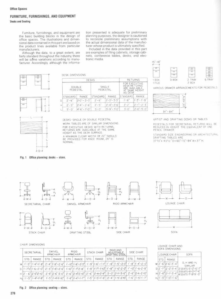
Office Spaces
FURNITURE, FURNISHINGS, AND EQUIPMENT'Desks and Seating
Furniture, furnishings, and equipment arethe basic building blocks in the design ofoffice spaces . The illustrations and dimen-sional data contained in this part are based onthe product lines available from particularmanufacturers .
Although the data, to a great extent, arefairly standard throughout the industry, therewill be some variations according to manu-facturer Accordingly, although the informa-
tion presented is adequate for preliminaryplanning purposes, the designer is cautionedto reconcile preliminary assumptions withthe actual dimensional data of the manufac-turer whose product is ultimately specified .
Included in the data provided in this partare examples of filing cabinets, storage cabi-nets, conference tables, desks, and elec-tronic media .

Office Spaces
FURNITURE, FURNISHINGS, AND EQUIPMENTChairs
Chair types are often associated with cer-tain generic job titles . The designer, however,is cautioned not to make assumptions as tochair selection without a thorough under-standing of the tasks the individual is toperform . Ergonomic considerations are to becarefully reviewed in order to select a chairwith appropriate attributes, i .e ., seat height,adjustability, back and arm support, firmness,etc . Overall chair size must be understoodwithin the context of available clearances andworkstation configuration .

Oftice Spaces
FURNITURE, FURNISHINGS, AND EQUIPMENTChairs

Office Spaces
FURNITURE, FURNISHINGS, AND EQUIPMENTChairs

Office Spaces
FURNITURE, FURNISHINGS, AND EQUIPMENTReception and Lounge Seating
Fig . 3 Reception and lounge seating canassume various sizes, shapes, and configura-tions . Modular seating units can offer a custombuilt-in look, and can often incorporate tableand storage components . Overall sizes will varyfrom manufacturer to manufacturer .

Oftice Spaces
FURNITURE, FURNISHINGS, AND EQUIPMENTConference Tables
Conference tables come in an infinitevariety of shapes and sizes. Figures 4 to 6attempt to provide a representative samplingof such tables, along with dimensional infor-mation and seating capacities . The designeris cautioned to use such information as apreliminary planning tool only, and to carefullylay out conference rooms with actual fur-niture pieces that have been selected . Chairwidth and spacing will ultimately dictateconference table seating capacity

Oftice Spaces
FURNITURE, FURNISHINGS, AND EQUIPMENTConference Tables

Office Spaces
FURNITURE, FURNISHINGS, AND EQUIPMENTVertical File Cabinets
Standard vertical file cabinets are usuallydesigned to accommodate standard heightdrawers and half-height file insert drawers(optional) . Cabinets are available in letter-sizewidths (14'/8") and legal-size widths (17'/8") .Vertical file drawers are usually 12" high andaccommodate front-to-back filing .
Standard cabinets are available in fourheights : five-drawer (585/8"), four-drawer(523/8"), three drawer (411/4"), and two-drawer(293/8' or 273/8") . The depths of the three-,four-, and five-drawer cabinets are 28 9/,6",while the depth of the 2-drawer cabinets is30". Table 1 lists these dimensional data . Itshould be noted that although adequate forpreliminary planning purposes, the data arebased on Steelcase cabinets .Guidelines for Customizing VerticalFilesDepending on the manufacturer, vertical filecabinets can be customized . Usually twohalf-height file insert drawers may be sub-stituted for a 12-in-high drawer in any or allpositions . Table 2 indicates the dimensionsand linear capacities of such insert drawers,while Fig . 7 illustrates basic guidelines forcustomizing .

Office Spaces
FURNITURE, FURNISHINGS, AND EQUIPMENT
Vertical File Drawers ; Overfile Cabinets ; Roll-Away Carts
TABLE 2
Vertical File Insert Drawers
Description
Half-height (3x5 or 46 cards)
Half-height (checks)Half-height (cash)
Half-height (box)
Half-height (microfilm)Full height (letter size)Full height (letter size)Full height (box)Full height (3x5 cards)Full height (4x6 cards)Full height (legal size)Full height (legal size)
*Deduct 5/e" when compressor is used .
Depth
26'/8"
26'/8"*81/4"81/2"43/8"
267/8"
261/4"*267/8"*267/8"*267/8"267/8"*26'/8"*26'/8"*267/e"*
Inside dimensions
Width
6"(2)
103/4"31/4"
1 1 1/2"2'/4"
12'/4"
4"(3)6"(2)4"(3)
5"(3)61/4"(2)7 1/2"(2)5"(3)
Height
43/8"
43/8"17/e"17/81113/4"43/4"
43/8"10 1/8"10 1/8"43/4"41/2"43/8"
10 1/8"10'/e"
Linear capacity
53'/e"* (2 rows)
267/8"BillsStorageCoin tray26'/8" front-to-back121/4" side-to-side80 3/4"* (3 compartments)53 7/8"* (2 compartments)80 3/4"* (3 compartments)
80 3/4"* (3 compartments)53 7/8" (2 compartments)See style no . CSee style no . D

Oftice Spaces
FURNITURE, FURNISHINGS, AND EQUIPMENTLateral File Cabinets
Standard lateral file cabinets are usuallyavailable in three widths-30", 36", and 42"-and with 12"-high drawers or roll-out shelves.Some cabinets are designed on a 3" moduleto accommodate 3"-, 6"-, 9"-, 12"-, and 15"-highdrawers and shelves.Ganging hardware is usually included with
each file cabinet. Cabinets should be gangedwith adjacent files or bolted to the floor.Counterbalance weights should be used forsingle-application files .Table 4 shows the outside and inside
dimensions of four lateral file cabinets, andtheir loaded floor weights based on 12"-highdrawers filled to capacity.
It should be noted that the dimensionaldata and load factors are based on Steelcasecabinets . Although these data are adequatefor preliminary planning purposes, it is essen-tial that the data of the equipment beingspecified are verified with its manufacturer

Office Spaces
FURNITURE, FURNISHINGS, AND EQUIPMENTLateral File Cabinets
Filing ArrangementsMost lateral file drawers are designed forfiling both letter-size and legal-size docu-ments, in addition to EDP printouts . Lateralfile drawers can usually accommodate mate-rials in a front-to-back (F to B) arrangement orin a side-to-side (S to S) arrangement . Insome instances a combination of the two ispossible . The actual capacity in linear inchesfor each arrangement and for each particulardrawer or shelf has been calculated and isshown in the "Linear capacity" column inTables 2, 3, 6, 7 and 8. It should be noted thatthe dimensional data in Table 5 are based onSteelcase drawers.

Office Spaces
FURNITURE, FURNISHINGS, AND EQUIPMENTLateral File Cabinets

Office Spaces
FURNITURE, FURNISHINGS, AND EQUIPMENTStorage Cabinets
Standard cabinets often provide a fast,flexible, and economical solution to manystorage problems . Table 7 provides dimen-sional data and capacities for four typicalcabinet types. These cabinets are manufac-tured by Steelcase. The dimensions of cabi-nets of other manufacturers will differ some-what . The data in Table 7, however, areadequate for preliminary planning purposes .

Office Spaces
FURNITURE, FURNISHINGS, AND EQUIPMENT
Interior Card Trays
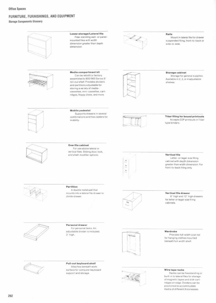
Office Spaces
FURNITURE, FURNISHINGS, AND EQUIPMENTStorage Components Glossary
RailsMount in lateral file for drawer
suspended filing, front-to-back orside-to-side .
Storage cabinetStorage for general supplies .
Available in 2, 3, or 4 adjustableshelves .
T barflling for boundprintoutsAccepts EDP printouts in T-bar
type binders .
Vertical fileLetter- or legal-size filing
cabinet with depth dimensiongreater than width dimension . Forfront-to-back filing only.
Vertical file drawer6" high and 12" high drawers
for letter or legal-size filingcabinets .
WardrobeProvides full-width coat rod
for hanging clothes mountedbeneath full-width shelf .
Wire tape racksRacks can be freestanding or
built-in to lateral files for storageof magnetic tapes and disk cart-ridges on edge. Dividers can bepositioned to accommodatemedia of different thicknesses .
Lowerstorage/Lateral fileFree-standing wall- or panel-
mounted files with widthdimension greater than depthdimension .
Media compartment kitCan be retrofit or factory
assembled to 800/900 Series 6"roll-out shelf, Provides dividersand partitions adjustable forstoring a variety of media-cassettes, mini-cassettes, cart-ridges, floppy disks, and more .
-_ Mobile pedestalSupports drawers in several
combinations and has casters formobility.
Overflls cabinetFar use above lateral or
vertical files . Sliding door, lock,and shelf-modifier options .
PartitionA double metal wall that
mounts into a lateral file drawer todivide drawer.
Personal drawerFor personal items . An
adjustable divider is included .3" high .
Pull-out keyboard shelfAttaches beneath work-
surface for computer keyboardsupport and storage.

Office Spaces
FURNITURE, FURNISHINGS, AND EQUIPMENTStorage Components Glossary
File Insert drawersFor use in vertical files
instead of card trays .
HangingfolderframeA metal rod mounted in lateral
and vertical files for suspendedfile material . Can be mounted onpartitions for front-to-back filing .
Interior card traysPortable trays in various
sizes for commoncard sizes :3 x 5, 4 x 6, etc . Compressorincluded .
Later file drawer3" tray drawer, 6" card drawer,
and 9", 12" and 15" high filedrawers . Letter or legal-size filing .Dividers, three sway blocks, com-pressor, hanging folder frames,rails, or partitions available .
Lateral file fixed shelf12" or 15" high shelves with
or without doors and with threedividers .
Lateral file posting shelfMetal pull-out shelf option on
48" and 60" interior height lateraltiles When not specified, thespace will be filled by a postingshelf filler.
Lateral file roll-out sheaf3", 6", 12", and 15" high
shelves extend for accessibility.
Lateral file workshelf3" high roll-out workshelf
with laminate surface .
BookcaseUnits have adjustable
shelves which can accommodaterows of standard ring binders andother bound materials .
Centerhookfiling hanging barAccepts printouts and
magnetic tape reels with centerhooks .
Combination wardrobe andstorage cabinet
Units are divided - space forhanging clothes and two or threevertically adjustable shelves .
CompressorA spring-loaded plate that
supports file material . Can bemoved and locked in position .Used in vertical and lateral filedrawers, pedestal file drawersand card trays .
DividerMetal plate used to separate
and support file material . For lat-eral file and pedestal file drawers,fixed and roll-out shelves .
Double-door storage cabinetfor miscellaneous storage
belowworks uriace, Includes oneadjustable shelf and two swing-arm doors .
FiledrawerFor letter- or legal-size docu-
ments 12" and 15" high . 15" highdrawers can also be used forcomputer printouts . For front-to-back or side-to-side or combina-tion filing .

Office Spaces
FURNITURE, FURNISHINGS, AND EQUIPMENT
Electronic Media Storage
Description Microfiche is a 4" x 6" filmtransparency containing multiple rows ofgreatly reduced page images of any written,printed or graphic material . Image reductionsrange from 13 up to several hundred timessmaller than the originals . A microficheviewer enlarges the images so that they arereadable . Labeling information is written orprinted on a narrow strip along the long edgeat the top of the microfiche .
Microfiche may be stored in interior cardtrays, in lateral file 6"-high roll-out shelves,and in a lateral file media compartment.
Description Microfilm is roll photographicfilm on a reel or in a square cartridge thatcontains images of pages of written, graphicor printed material reduced hundreds oftimes. A microfilm viewer enlarges the im-ages so that they are readable . Microfilm on areel is kept in a square plastic or cardboardbox for protection and ease of handling .Microfilm is most conveniently stored onedge . Labeling is placed on one of the edgesof the reel or box.
Microfilm may be stored in the lateral filemedia compartment kit, in an interior cardtray, and in lateral file 6"-high drawers orshelves .
Description Print-out paper, also known ascontinuous form data processing paper, isused in almost all computer printers andsome word processing equipment. The mostcommon types are recognizable by :
Small "pin-feed" holes along bothedges which are used by the printer to gripand advance the paperm Green or grey-shaded stripes across the
paper which serve to organize the printedinformation .After printing, the print-out may exist in a
"fan-folded" stack or it may be "burst;' i .e .,separated into individual sheets along theperforations that exist at the fold lines.
If the print-out consists of a significantnumber of sheets, it may be "bound" foreasier handling . Fan-folded printouts mustbebound along the top or long edge . Print-outs
that have been burst may be bound alongeither the long edge or the short edge . Thebinding mayconsist of only a narrow metal orplastic clamp or it may be include a stiffplastic or fiberboard cover. Frequently thebinding may include hooks at both ends sothe print-out maybehung from two rails like ahanging file folder Other hooks may be usedto suspend it from special bars or rails .
Identification information may be markedon one of the edges (depending on how theprint-out is stored) oron the front sheet of thebinding cover
Print-out paper may be stored in Steelcaselateral and vertical files depending on thepaper size . Check the file which will accom-modate your paper. Boxed paper can bestored in storage cabinets .
Description
Cartridges have '/4" wide mag-netic tape loaded into a reel-to-reel cartridgegenerally made of clear plastic with metalback plate . They look similar to an oversizerecording cassette . Cartridges come in andare sometimes stored in a "flip-open" plasticor cardboard box. Labels or identificationinformation are located on the long edge oron the side along the long edge of thecartridge or the box.
Cartridges may be stored in interior cardtrays or in a media compartment kit in lateralfile 6"-high drawers or shelves.

Description Cassettes are available in"standard" and "mini" sizes and consist ofmagnetic tape loaded into a reel-to-reel con-figuration in a plastic case . Standard cas-settes for electronic equipment are identicalin size and appearance to those used forhome recording . Cassettes may be used inmicrocomputers and in word processing ordictation equipment. They come in and arefrequently stored in a flip-open plastic case .Labels or identification information may belocated on the long edge or side of thecassette or its case .
Cassettes may be stored in a lateral filemedia compartment kit .
Description
Disk cartridges are round plasticcases which contain a series of rotatingplatters (or disks) on which data is magnet-ically recorded . The number of platters in acase varies with the height of the case . Inuse, the entire case is inserted in a computerdisk drive unit where recording arms, whichread/record information, enter the casethrough a slot with a spring door.
Disk cartridges are flat in appearance withan elongated Y-shaped protrusion on the top.They can be stored flat or on edge.
Labels for identification are usually locatedon the edge of the disk cartridge. Frequentlydisk cartridges have to be stored in a tem-perature/humidity controlled environment .
Disk cartridges may be stored in lateral file6"-high roll-out shelves, storage cabinets,and bookcases.
Description Disk packs are round plasticcases which contain a series of rotatingplatters (or disks) on which data is magnet-ically recorded . The number of platters in aunit varieswith the height of the plastic case .In use, the entire case is inserted in acomputer disk drive unit where recordingarms, to read/record information, enter thecase through a slot with a spring door. Diskpacks are flat on the bottom and upright withthe handle on top. Identification is generallylocated on the edge of the disk pack . Theseunits should be stored in a temperature/humidity controlled environment. Disk packsmust not be stored one on another
Disk packs may be stored in storage cabi-nets, bookcases, and on 3"- and 6"-highlateral file shelves.
Description Floppy disks, also called disk-ettes or flexible disks, are small record-likedisks each permanently enclosed in a square,stiff paper envelope . They are used to mag-netically record information in all types ofsmall computer and word processing equip-ment . Labels are placed on the paperenvelope .
Floppy disks may be stored in 12"-highlateral file drawers and shelves.
Office Spaces
FURNITURE, FURNISHINGS, AND EQUIPMENT
Electronic Media Storage

Oftice Spaces
FURNITURE, FURNISHINGS, AND EQUIPMENT
Electronic Media Storage
Description Laser disks look like long-playrecord albums complete with a paper protec-tive sleeve . Data are stored and retrieved bylaser beam .
Laser disks may be stored in 15"-highlateral file drawers and shelves.
Description
Magnetic cards, also known asmag cards, are a tab-size black plastic cardwith magnetic material coated on one or bothsides . The cards are used to record orreproduce information in word processingequipment. In some cases one or more of thecards will be kept in a paper envelope .Identifying information will be marked on theface of the envelope .
Tab cards, also known as keypunch cards,are 80 column cards or punch cards withsmall holes in them to represent bits of data .Although they may be stored in aworkstationor central storage area, they are usually usedand produced in a mainframe computer roomor keypunch department, and are stored in
specially separated decks. The decks aremost frequently identified by markingsacross the edges of the cards.Aperture cards are tab cards with a piece
of microfilm mounted over a hole in theircenter. They are most frequently used formicrofilm images of engineering or architec-tural drawings . Aperture card reader/printersenlarge the image on a screen for referenceand, if required, reproduce a full-sized copyofthe drawing . Identifying information isprinted in a narrow band along the top (longedge) of the card .These cards maybe stored in interior card
trays and in lateral file 6"-high drawers androll-out shelves.
Description Magnetic tape is typically %z"wide and loaded on reels of varying diame-ters . A flexible plastic strip locks around theoutside of the reel to protect the tape andprevent unraveling when it is not in use. Thismedia is used in large tape drive units that aregenerally found only in computer rooms. Thelong-term storage of magnetic tapes is sub-ject to strict temperature and humidity re-quirements to prevent damage . Tapes arelabeled both on the side and on the flexiblestrip that is placed around the edge of thereel . They can be stored flat or on edge . Forflat storage, handle like disk cartridges .
Magnetic tape reels may be stored in thelateral file add-on cabinets, storage cabinets,or in free-standing wire racks on lateral fileshelves.

Office Spaces
FURNITURE, FURNISHINGS, AND EQUIPMENTFile Countertop

office Spaces
FURNITURE, FURNISHINGS, AND EQUIPMENTFile Countertop with Shelf Light

Office Spaces
FURNITURE, FURNISHINGS, AND EQUIPMENTFile Storage Walls with Overhead Cabinets

Office Spaces
FURNITURE, FURNISHINGS, AND EQUIPMENTOffice Pantry

Office Spaces
FURNITURE, FURNISHINGS, AND EQUIPMENTOffice Pantry

Office Spaces
FURNITURE, FURNISHINGS, AND EQUIPMENT
Office Pantry

Office Spaces
FURNITURE, FURNISHINGS, AND EQUIPMENTCountertop with Base Cabinets

Office Spaces
FURNITURE, FURNISHINGS, AND EQUIPMENT
Island File Counter ; Compact Kitchen
ISLAND FILE COUNTER

Hospitality SpacesRestaurants
307Bars
346Hotels
374


Hospitality Spaces
RESTAURANTSTypes and Sizes of Table Arrangements
The basic components of any restaurantrterior are the chair and the table. Depend-rg upon restaurant type, menu, service,'We setting, furniture selection, and degreeY intimacy required, table size and overallaair space requirements can, and should,nary greatly. A restaurant that encouragesapid turnover of customers will normally:fovide smaller table top and chair sizes. OnTe other hand, those restaurants that en-xxwrage limited turnover and emphasize theinning and dining experience will typically
provide larger table top sizes and larger, morecomfortable chairs, with greater distancebetween table groupings .There is no agreement among even the
most experienced restauranteurs and restau-rant designers as to what the optimal tableand chair dimensions should be . In addition,many other design factors will influence thefinal decision, including circulation andegress, accessibility standards, methods ofservice, and the overall dimensions of anygiven space.
Figures 1 to 19 provide the designer withrestaurant planning standards that have beendeveloped by many experienced architectsand interior designers. These drawings notonly show the various individual table andchairarrangements, but provide the designerwith groupings of these arrangements, as wellas an indication of overall size, floor area, andnumber of persons accommodated . Thesearrangements, however, should only be uti-lized for preliminary planning information.

Hospitality Spaces
RESTAURANTS
Types and Sizes of Table Arrangements

Hospitality Spaces
RESTAURANTS
Types and Sizesof Table Arrangements

Hospitality Spaces
RESTAURANTStypes and Sizes of Table Arrangements

Hospitality Spaces
RESTAURANTSTypes and Sizes of Table Arrangements

Hospitality Spaces
RESTAURANTS
Tables: Design Criteria
Fig . 10
These drawings highlight several criticaldimensions that the designer must consider. Aislecirculation must be adequate in width ; other clear-ances to consider include chair depth from edge oftable and clearance between chairs . While layingout chair and table arrangements, a designer mustanticipate the potential conflict between a patronleaving a seat and atray-carrying waiter.

Hospitality Spaces
RESTAURANTSTypes and Sizes of Banquette Arrangements

Hospitality Spaces
RESTAURANTSTypes and Sizes of Banquette Arrangements

Hospitality Spaces
RESTAURANTSTypes and Sizes of Banquette Arrangements

Hospitality Spaces
RESTAURANTSDining Room Seating
Restaurant and Dining Room Seating
Dispersed seating suitable for guests withrestricted mobility should be available inrestaurants, coffee shops, and dining facili-ties . As a guide, the Uniform Federal Ac-cessibility Standards (UFAS) require a mini-mumof 5 percent of restaurant seating to beaccessible . Accessible aisles should connectthe entrance to these seating locations,public restrooms, and self-service areas suchas salad bars, condiment stands, or buffettables . Comfortable seating for waitingshould be available to customers near theentrance .A variety of accessible seating should be
available, suitable for large and small dininggroups . Small tables may not be accessibleto guests in wheelchairs because of therestricted kneespace. Therefore, a party ofone or two mayrequire a table usually setupfor four. Restaurants or coffee shops withbuilt-in seating, such as booths or ban-quettes, should also provide some chairs forguests who have difficulty getting into andout of bench seating. These chairs can beremoved to seat guests in wheelchairs .Where seating areas are raised on platforms,accessible seating and similar servicesshould be available on the main-floor level ora ramp to the upper level should be provided .Aisles serving accessible seating should
be at least 3'0" wide, which typically requiresa 6'0" clearance between parallel tables, or4'6" between rotated tables . (See Fig. 21 .)Aisle widths should also provide room forcustomers to be seated at tables . At least a2'6" clear space should be available behindeach seating location . This space allowschairs to be withdrawn from the table andstaff to assist guests reposition chairs closeto the table.
For wheelchair seating, a 3'0" to 3'6" aisleis necessary, depending on the width of thekneespace . (See Fig . 25 .) Wheelchairs posi-tioned at tables project approximately 5"further into aisles than most chairs . To allowguests with restricted mobility to turnaround, seating arrangements should alsoinclude a 5'0" diameter circle or Tshapedclear area at dead-end aisles .
Dining Tables and Chairs
Accessible seating locations should allowguests with restricted mobility to dine withambulatory customers. Tables should pro-vide kneespace for customers in wheel-chairs, and dining chairs should be coordi-nated to provide comfortable seating at thesame table height .
Dining room chairs should be stable tomaintain balance as guests seat themselves,and comfortable to sit in during dinner. Chairsshould be light and easy to reposition . Theseat should have a slight slant to the rear totransfer body weight to the back of the chair.However, an exaggerated incline makes itdifficult to rise . The seat should be approx-imately 16" deep and at least 16" wide toallow space for customers to repositionthemselves during the meal . Padding orcushions on the chair seat should be firm,and the chair back should also be slightlyinclined to the rear. To help guests sitand rise,dining chairs should have armrests 7" to 8"above the front edge of the seat . (See Fig.22 .) Supports or cross-bracing should not

Hospitality Spaces
RESTAURANTSDining Tables and Chairs
-terfere with kickspace below the seat, soone feet can be positioned to rise . The frontedge of the chair seat should be low enoughro allow the feet to rest on the floor, but not soow that it is difficult to rise . This is deter--nined by the lower leg length (poplitealeight) which varies between 15" and 20" for
most adults.The height of the chair seat should be 101/2"
to 11112" below the top of the table . Commonseat heights vary between 14" and 18" .Because the height of wheelchair seats istypically 19", a relatively high chair seat isnecessary to coordinate with the tableheight . A chair with an 18" high seat iscomfortable for most ambulatory guests andclosely approximates the height of a wheel-chair seat .
Dining room tables should have a stablesurface at a convenient height and knee-space and legroom below the tabletop forcustomers in wheelchairs . Narrow table con-figurations allow face-to-face seating, which
reduces the distance between diners, mak-ing conversation easier and table lightingmore effective . For safety, the corners andedges of the top should be rounded .
Full-height wheelchair kneespace is 2'6",which requires tabletops to be at least 2'7"above the floor, too high for most seating .Many wheelchairs now provide adjustable ortwo-tier armrests, which allow customers tosit close to tables in a kneespace only 2'3"high . To provide this kneespace, the tabletop(without an apron) should be 2'4%2" to 2'5"above the floor. This is 11" to 11112" above thechair seat, 101/2" to 11" above the seat ofwheelchairs, and convenient for both . Thiskneespace also permits the armrests ofchairs to pass below the tabletop so seatedcustomers can draw close . This combinationof tables and chairs is suitable for the majorityof wheelchair users and most ambulatoryguests .Footroom is important for customers with
wheelchairs or leg braces . The footrests of
wheelchairs are 21/2" to 3" above the groundand angled slightly forward, which requires1'7" of footroom, measured from the edge ofthe tabletop . The outside width of footrests isonly 1'6", but 2'6" of side-to-side clearance isnecessaryto maneuver into position beneaththe table . To provide kneespace, table legsshould be at least2'6" apart, and the tabletop,for face-to-face seating, should be 3'6" wide .Pedestalbase tables should have low, ta-pered bases and a minimum diameter of3'6", although 4'0" is preferred .A portable raised leaf should be available to
modify tables for customers in wheelchairswith high armrests . The leaf should be ap-proximatelythe size of a place setting, 1'4" by2'0", and secured to the underside of anaccessible table with clamps . The raised leafshould project 6" beyond the edge of thetable and provide 2'6" clearance above thefloor. (See Fig . 24 .)

Hospitality Spaces
RESTAURANTSBanquettes : Design Criteria
Figure 27 shows the basic dimensions forthe design of banquette seating . The lack ofarmrests makes it difficult to define seatboundaries . The user, therefore, tends toestablish a territory by assuming a desiredsitting posture and placing personal articlesnext to him or her, such as a briefcase, purse,or package . Since the nature of this type ofseating can permit some form of body con-tact, hidden dimensions and personal spacealso play an important part in how close theusers sharing the banquette will sit .Because of the many hidden psychological
factors involved, the actual efficiency of thisseating type in terms of capacity is question-able . Figure 27 indicates two possible seat-ing situations, each dictated by the an-thropometrics involved . One arrangement isbased on the premise that the user's elbowswill be extended, possibly in conjunction withsome activity, such as reading, or simply asan attempt to stake out additional territory, aswould be the case in the strategic positioningof some personal article on the seat . In thissituation it would be reasonable to assumethat each user would take up about 30 in, or76 .2 cm, of space . The other diagram showsa more compact seating arrangement . Figure26 shows a section through a typicalbanquette .
in cmA 18-24 45.7-61 .0
15.5-16 39.4-40.6C 16-17 40.6-43.2D 30 76.2E 24
61 .0

Hospitality Spaces
RESTAURANTSBanquette/Bench Seating Details
Banquette seating provides the designerwith one of the few opportunities to customdesign restaurant seating . While there canbe a great variety of aesthetic solutionsachieved through use of various materials,ergonomic considerations must be analyzedcarefully. Specific attention should be givento depth of seat, slope of seat and back,height of back, and relationship of seat heightto table height .

Hospitality Spaces
RESTAURANTSBanquette/Bench Sealing Details

Hospitality Spaces
RESTAURANTSBanquetterBench Seating Details
Banquette seating can be detailed rela-tively simply, as Figs . 28 to 30 suggest. Thesimplest form of banquette seating may takethe form of a plywood seating platform with aremovable seat cushion, or a box cushionseat and back support . Such seating is appro-priate in fast food or quick turnover restau-rant operations .

Hospitality Spaces
RESTAURANTS
Lunch Counters : Design Criteria
Figure 31 shows some of the basic clear-ances required for a typical counter: 36 in, or91 .4 cm, for workspace behind the counter;18 to 24 in, or 45 .7 to 61 cm, for the countertop ; and 60 to 66 in, or 152 .4 to 167.6 cm,between the front face of the counterand thenearest obstruction. Figure 32 shows a sec-tion through the counter and back counter.Most counters are about 42 in, or 106.7 cm, inheight . The clearance from the top of the seatto the underside of the counter top and thedepth of the counter top overhang are ex-tremely important. Buttock-knee length andthigh clearance are the key anthropometricmeasurements to consider for proper bodyfit . Footrest heights should take into consid-eration popliteal height . In most cases this isignored, and 42-in counters are provided with7-in, or 17 .8-cm, footrests that are 23 in, or58.4 cm, below the seat surface, whichcannot work . The popliteal height of thelarger user, based on 99th percentile data, isonly about 20 in, or 50 .8 cm . Therefore, thefeet dangle unsupported several inchesabove the footrest and the body is deprivedof any stability. The footrest shown in Fig. 32,although higher, only serves a portion of theseated users and is intended primarily forstanding patrons. The most logical solution isa separate footrest, integral with the stool.
in cm
60-66 152 .4-167.618-24 45.7-61 .0
C 36
91 .424
61 .012-18 30 .5-45.735-36 88 .9-91 .4
Ca 42 106.7H 30-31 76 .2-78.7
11-12 27.9-30.5J 10
25.4K 12-13 30 .5-33.0

Hospitality Spaces
RESTAURANTSMiscellaneous Counter Details

Hospitality Spaces
RESTAURANTSMiscellaneous Counter Details

Hospitality Spaces
RESTAURANTSMiscellaneous counter Details

Hospitality Spaces
RESTAURANTSMiscellaneous Counter Details

Hospitality Spaces
RESTAURANTSMiscellaneous Counter Details
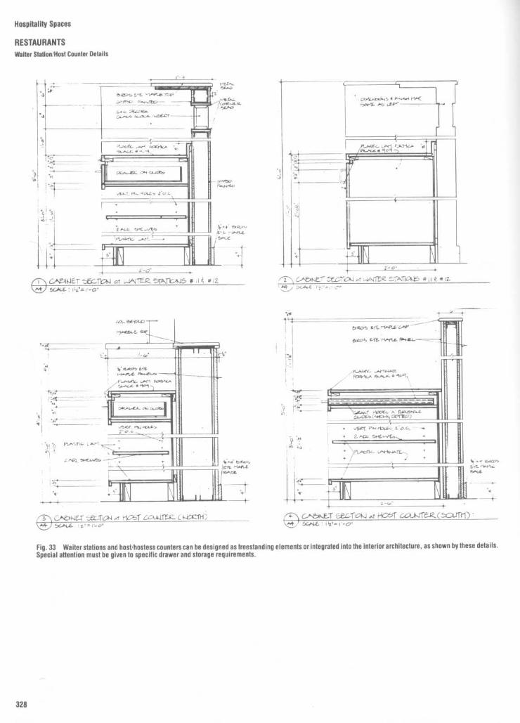
Hospitality Spaces
RESTAURANTSWaiter Slation/Host Counter Details
Fig . 33
Waiter stations and host/hostess counters can be designed as freestanding elements or integrated into the interior architecture, as shown by these details .
Special attention must be given to specific drawer and storage requirements .

Hospitality Spaces
RESTAURANTS

Hospitality Spaces
RESTAURANTSWheelchair Accessibility to Self-Service Areas
Self-Service AreasSalad bars, buffet lines, condiment stands,and other self-service areas should be ac-cessible . Cafeteria or food-service linesshould have a minimum width of 3'0", but awidth of 3'6" is recommended to permitambulatory customers to pass customers inwheelchairs .The tray slide should be 2'10" above the
floor, the maximum height for customers inwheelchairs and convenient for ambulatoryguests . The tray slide should be continuous,if possible, from the entrance to the cashier.Tray slides restrict access to the counters andtherefore should not be wider than neces-sary (1'0" recommended) . In this instance,the reach of a customer in a wheelchair isextended if the wheelchair can be angled orpositioned perpendicular to the tray slide .This is possible if the lower face of thecounter is recessed to provide low knee-space . (See Fig . 34 .)
For guests with a limited range-of-motion,food, beverages, utensils, or other itemsshould be displayed near the edge of thecounter where they are easier to see andreach . When duplicate items are displayed, avertical rather than horizontal arrangementallows customers to select items at the mostconvenient height . Self-service systems,such as beverage or ice-dispensers, shouldbe easy to operate without fine hand func-tion . Instructions and price informationshould be prominently displayed in largeclear lettering .
Salad bars and buffets should provide a3'0" -wide clear space for access on all sidesand plate slides, or areas to temporarily setplates, at a maximum height of 2'10" . Thispermits customers to serve themselves withone hand, without simultaneously balancingthe plate or bowl . Kneespace 2'3" high belowthe counter or table allows front wheelchairapproach, to increase customers' forwardreach . Condiments should be located as lowand close to the edge of the counter or tableas practical . A tilted mirror above the fooddisplay at salad bars also aids customers inwheelchairs and children . (See Fig . 35 .) Forsome customers with restricted mobility,poor balance, or limited hand function, it ismore difficult to carry a plate . Therefore traysshould be available at both salad bars andbuffets .

Hospitality Spaces
RESTAURANTSCafeteria Counter Plans, Elevations, and Details

Hospitality Spaces
RESTAURANTS
Lunch Counters : Cashier Station

Hospitality Spaces
RESTAURANTSCafeteria/Servery Counter Details

Hospitality Spaces
RESTAURANTSCafeteria/Servery Counter Details

Hospitality Spaces
RESTAURANTSCafeteria/Servery Counter Details

Hospitality Spaces
RESTAURANTScafeteria/Servery counter Details

Hospitality Spaces
RESTAURANTSCafeteria/Servery Counter Details

Hospitality Spaces
RESTAURANTS
Service Counter; Host Cabinet ; Waiter's Station ; Trash Counter

Hospitality Spaces
RESTAURANTSCondiment Cabinet; Dining Room Server

Hospitality Spaces
RESTAURANTSSalad Bar/Serving Counter

Hospitality Spaces
RESTAURANTS
Tray Pick-Up Details ; Condlment Counter Details

Hospitality Spaces
RESTAURANTSCondiment Counter Details
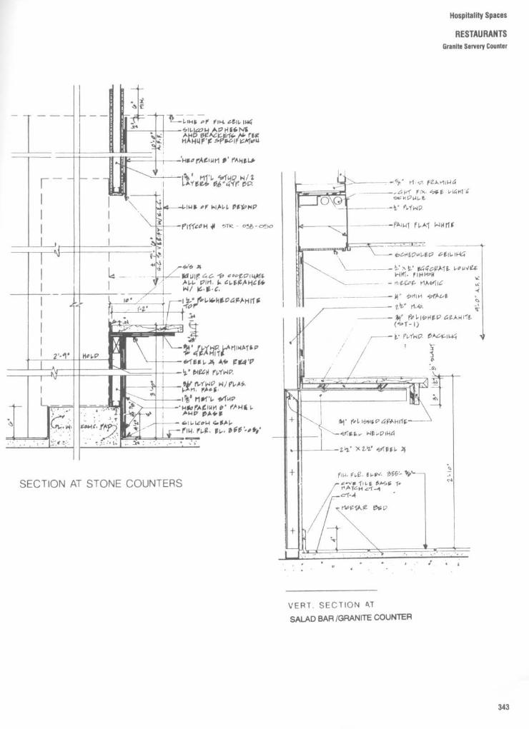
Hospitality Spaces
RESTAURANTSGranite Servery Counter
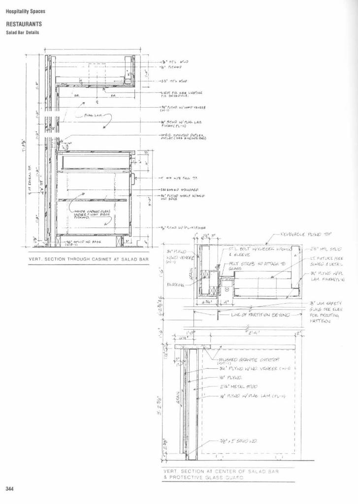
Hospitality Spaces
RESTAURANTSSalad Bar Details

Hospitality Spaces
RESTAURANTSServery Details

upitality Spaces
%RSr Section Details
The distance between bar and backbarshould allow adequate workspace . A mini-mum of 36 in, or 90 cm, should provide spacefor one bartender to serve and another tocirculate behind . Maximum body depth andmaximum body breadth are the primaryanthropometric considerations in establish-ing clearance. A one-bartender operationwould require a 30-in, or 75-cm, clearance .
In regard to bar stools, clearance betweenthe stool seats is more critical than centerline spacing, and it should allow patrons oflarger body size a comfortable side approachand departure from the stool without bodycontact with the next person . A 12-in, or 30-cm wide stool on 24-in, or 61-cm, centers,which is quite common, will allow only lessthan 5 percent of male users access to thestool without disturbing the next patron,while a 30-in, or 75-cm, spacing will accom-modate 95 percent of the users . The tradeoffhowever, would be the loss of two seats forevery 120 in, or 300 cm, of bar length . Aspacing of 12-in stools on 28-in, or 70-cm,centers is suggested as a compromise . Theultimate decision is an individual one andmust reconcile human factors with economicviability.
in
cm
18-24 45 .7-61 .0C 24
61 .0p 30
76.216-18 40 .6-45.7
F 24-30 61 .0-76.2G 30-36 76 .2-91 .4
28-38 71 .1-96.5100-128 254 .0-325 .1
J 42-45 106 .7-114.3K 11-12 27.9-30.5L 6-7 15.2-17.8M 7-9 17.8-22.9
6-9 15.2-22.922-26 55 .9-66.0
P 60-69 152.4-175 .336-42 91 .4-106.7

Hospitality Spaces
BARSCounterTypes and Sizes
To ensure proper circulation and interface,adequate clearances in front of the bar areillustrated in Fig . 2. A customer activity zoneof 18 to 24 in, or 45.7 to 61 .0 cm, should beprovided to allow for seating, standing, andaccess, in addition to a general circulationzone of at least 30 in, or 76 .2 cm . If asupplementary drinking surface or shelf isprovided, a smaller activity zone of 18 in issuggested in front of the shelf. The shelf canbe 10 to 12 in, or 25 .4 to 30 .5 cm, deep . Figure3 shows suggested clearances for 18 or 24 incocktail tables .
in cm76-84 193.0-213.466-72 167.6-182.9
C 10-12 25.4-30.518
45.730
76 .218-24 45.7-61 .076
193.054-56 137.2-142 .26-9 15.2-22 .9
J 7-9 17.8-22.9K 42-45 106.7-114 .3L 24
61 .0M 29-33 73.7-83 .8
32-36 81 .3-91 .4

Bar shapes, seating capacities, overall o-mensions, and "footprints" of bar areas vangreatly. Figures 4 to 22 show examples of bardesigns drawn at a scale of 1/4" = 1'0" . Carefjstudy of these designs would suggest tha-seating width, spacing, and circulation areasmust be given special attention .
Hospitality Spaces
BARSDar Shapes : Planning Criteria

Hospitality Spaces
BARS
Bar Shapes: Planning Criteria

Hospitality Spaces
BARS
Bar Shapes: Planning Criteria

Hospitality Spaces
BARSBar Shapes: Planning Criteria

Hospitality Spaces
BARSBar Shapes : Planning Criteria

Hospitality Spaces
BARSBar Shapes : Planning Criteria

Hospitality Spaces
BARS
Bar Shapes : Planning Criteria

Hospitality Spaces
BARSBar Shapes : Planning Criteria

Hospitality Spaces
BARSSar Shapes : Planning Criteria

Hospitality Spaces
BARSBar Plans, Elevations, and Sections
The detailing of bars and backbars can varyfrom the very simple and basic to the compli-cated and intricate . Figures 23 to 40 providethe designer with selected examples ofworking drawings from some of the mostexperienced restaurant and hospitality de-sign firms in the world. Careful review ofthese drawings would suggest that overalldimensions and clearances vary from detailto detail . In that regard, individual require-ments based upon bar type and the hospi-tality area serviced must be given carefulconsideration . In addition, local buildingcodes and health codes must be consulted.

Hospitality Spaces
BARSBar Plans, Elevations, and Sections

Hospitality Spaces
BARSBar Plans, Elevations, and Sections

Hospitality Spaces
BARS
Bar Plans, Elevations, and Sections

Hospitality Spaces
BARS
Bar Plans, Elevations, and Sections

Hospitality Spaces
BARS
BarPlans, Elevations, and Sections

Hospitality Spaces
BARS
Bar Plans, Elevations, and Sections

Hospitality Spaces
BARSBar Plans, Elevations, and Sections

Hospitality Spaces
BARSBar/Serving Counter Details

Hospitality Spaces
BARSBar Plans, Elevations, and Sections

Hospitality Spaces
BARS
Bar Plans, Elevations, and Sections

Hospitality Spaces
BARSBar Section Details

Hospitality Spaces
BARSBar Section Malls

Hospitality Spaces
BARS
Bar Section Details

Hospitality Spaces
BARSBar Section Details

Hospitality Spaces
BARSBar Section Details
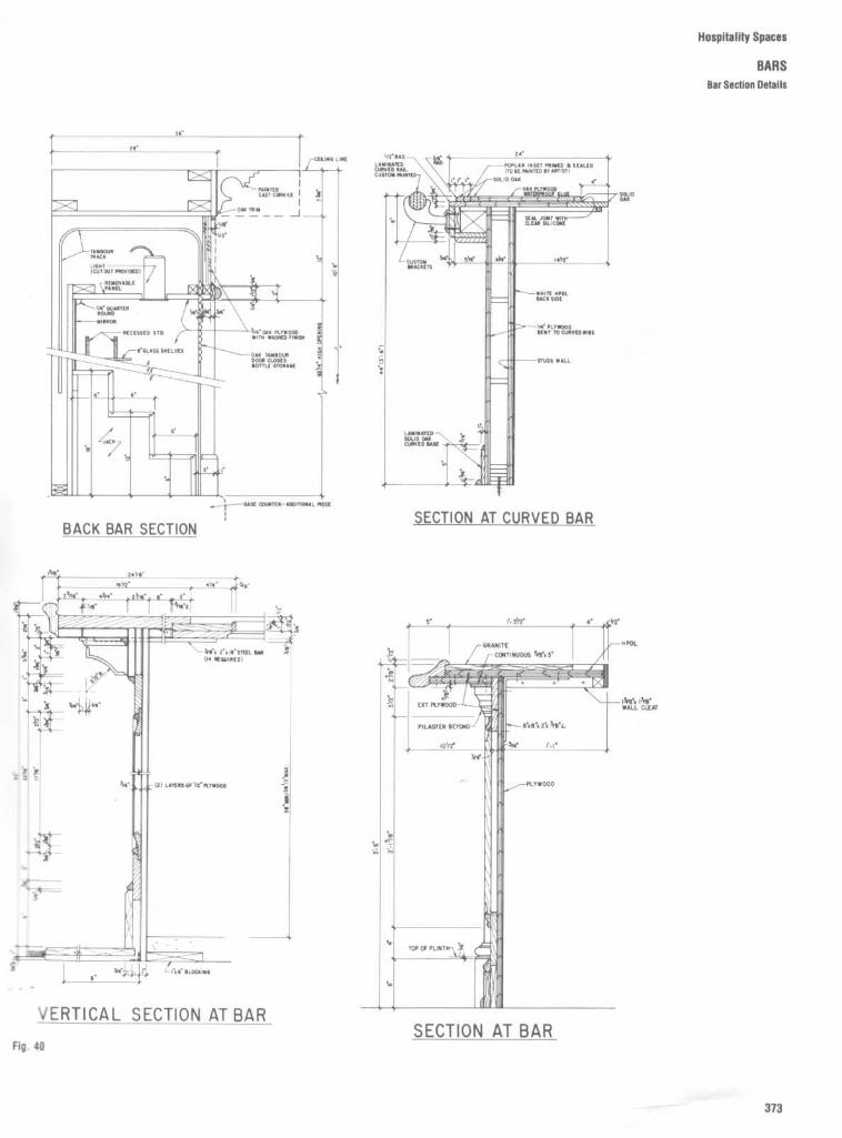
Hospitality Spaces
BARSBar Section Details

Hospitality Spaces
HOTELSGuestroom Plans
It is interesting to note how trends in hoteldesign have headed off in two directions,especially in regard to the design of rooms.On one hand, an effort is being made toprovide more luxurious multipurpose roomgand suites . The hotel room as office awayfrom work or as fantasy sleeping/relaxationenvironment often results in rooms with
work areas, living rooms, and hot tubs, just toname a few of the more popular amenities.On the other hand, there is a trend towardeconomy accommodations . Hotel rooms arebeing designed as a place to rest and sleep, aplace to feel comfortable and safe at areasonable cost . Accordingly these roomsuse less floor area and provide less second-
ary or frill items. With both of these ap-proaches, however, designers must ensurethat the room or suite layouts are accessibleto the physically challenged . In that regard,various room layouts and bathroom plansare provided in this section that addressthis issue .
Fig . 1
(a) Uris Brothers Hotel, New York . (b) Americana Hotel, New York, typical tower room . (c) Loews NA Motel, typical room . (d)Causeway Inn, Tampa, Florida .

Hospitality Spaces
HOTELSGuestroom Plans
Fig . 2
Guestroom plans . (a) Typical double-double finishes plan : vinyl wallcovering (WC), paint(P), carpet (C), ceramic tile (CT) identified and keyed to legend . (b) King-studio (Holiday Inn) :standard layout with armoire unitand large lounge area including a convertible sofa . (c) Reversedlayout (Sheraton, Washington, D .C .) : unusual room with bed placed in front of window and loungearea near bathroom . (d) Luxury king room (Sheraton Grande, Los Angeles) : oversized room withshelf/ledge in place of headboard, large desk surface, and lounge area ; four-fixture bathroom .

Hospitality Spaces
HOTELSGuestroom Plans

Hospitality Spaces
HOTELSAccessible Guestroom Plans
Guestroom Plans
Accessible guestrooms have design featuresand floor plans that provide the maneuveringclearances for guests with limited mobility.=igures 5 to 9 show sample plans ofguestrooms and bathrooms with the-equ i red
Widths and clearances at the entry,connecting, closet, and bathroom doors
Maneuvering space in front of thecloset, in the sleeping area, and within theoathroom0 Clearances to use and transfer to fix-
,ures in the bathroomN Clearances to open dresser drawers, to
maneuver into kneespace at the desk, and toaccess the bed, bedside table, windows,blinds, and thermostat
Clearances may depend on the design ofspecific furnishings . The width of the accessaisle at the bed is determined by the designof the bedside table . Access to dressers isdetermined by the width of the drawer. Themaneuvering space to turn into the desk isdetermined by the width of the kneespace .

Hospitality Spaces
HOTELS
Accessible Guestruurn Plans
Fig . 15
This alternative 12'0" bay-spacing designrequires the dresser to be offset from the foot ofthe bed . The bathroom wall is stepped back toprovide clearances for the bathroom door andconnecting door. The heating/cooling unit projectsinto the room to allow access to the thermostat . Ifbalconies are provided, a minimum depth of 5'0"is recommended to allow guests with wheelchairsto turn around .
Fig. 7 A 13'0" bay-spacing provides room for wheelchairclearances, including a turning space in front of the closet and atthe foot of the beds, an access aisle between the beds, a T-turnaround at the window aisle for access to temperature controlsand blinds and drapes, door clearances, and a bathroom thatmeets ANSI standards .

Hospitality Spaces
HOTELS
Accessible Guestroom Plans
Suite with 14' Bay-spacingFig . 8
Accessible suites should meetthe same requirements for accessible guestrooms and guest baths . Becausesuites are usually more generous in terms of space, providing accessibility is less difficult . If a small kitchenette isincluded, a kneespace 2'3" high should be provided below the sink . A countertop height of 2'10"(2"lower thanstandard) is suitable for both ambulatory guests and guests in wheelchairs . A pull-out lapboard at a height of 2'6"provides a workspace for guests in wheelchairs . The kitchenette should include a 5'0" turning space .

Fig . 9
These two diagrams illustrate the same bathroom plan with the required clearances for door operation and turning space and access to each fixture,including the tub/shower, vanity, and water closet. Clearances for maneuvering space, door operation, and individual fixtures can "overlap ." Because of the verticalcharacteristics of wheelchairs, clearances can include toespace (9" high) below water closet and kneespace (2'3" high) below vanities .
Hospitality Spaces
HOTELS
Accessible Bathrooms

Hospitality Spaces
HOTELSRegistration Desk
The hotel registration desk serves as botha symbol of hospitality for the arriving guestand the operational nerve center for thehotel . With the advent of electronic check-inprocedures, credit cards, and computer-aided management, the registration desk hasbecome a sophisticated electronic worksta-tion not unlike a trading table or an airlinereservations desk . At the same time, thiselectronic data processing capability ismeant to be maintained at low visibility forreasons of hotel image and confidentialityAccordingly, the designer must be able to
project the appropriate hospitality imagewhile at the same time integrating all of therequired technologies . Figures 10 to 13 showexamples of architectural working drawingsand details that meet many of theserequirements .The design of a front desk or registration
desk can take many forms and be con-structed with a variety of materials . Re-gardless of the design vocabulary used orarchitectural style, certain important designconsiderations must be observed .
1 . The number of persons actively staffing
the counterlike facility will dictate both thewidth and overall depth of the front desk . It issuggested that between 5-7 ft be allocatedper staff workstation and that one worksta-tion be allocated for every 125-150 rooms .For every additional 125-150 rooms, an addi-tional workstation should be provided . Peakcheck-in/check-out loads could require evenmore staff workstations .
2 . The front desk should be easily accessi-ble from and to the main hotel entrance ."Easily accessible" strongly implies clearvisibility.
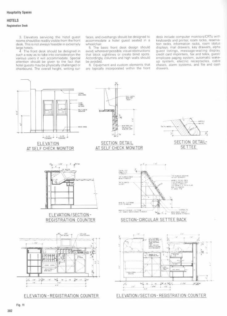
Hospitality Spaces
HOTELSRegistration Desk
3 . Elevators servicing the hotel guestrooms should be readily visible from the frontdesk . This is not always feasible in extremelylarge hotels .4 . The front desk should be designed in
such a way as to take into consideration thevarious users it will accommodate . Specialattention should be given to the fact thathotel guests may be physically challenged orchairbound . The overall height, writing sur-
faces, and overhangs should be designed toaccommodate a hotel guest seated in awheelchair.
5 . The basic front desk design shouldavoid, wherever possible, visual obstructionsthat block sightlines or create blind spots .Accordingly, columns and high walls shouldbe avoided .6 . Equipment and custom elements that
are typically incorporated within the front
desk include computer monitors/CRTs withkeyboards and printer, room racks, reserva-tion racks, information racks, room statusdisplays, mail drawers, key drawers, alphaguest listings, message-waiting display,credit card imprinters, fax and telex, guestemployee paging system, automatic wake-up system, electric receptacles, cablechases, alarm systems, and file and cashdrawers .
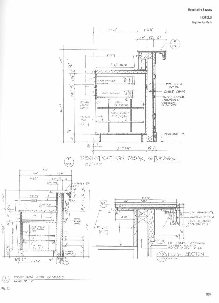
Hospitality Spaces
HOTELS
Registration Desk

Hospitality Spaces
HOTELSRegistration Desk

Retail SpacesShops
387Banks
396Department stores
401

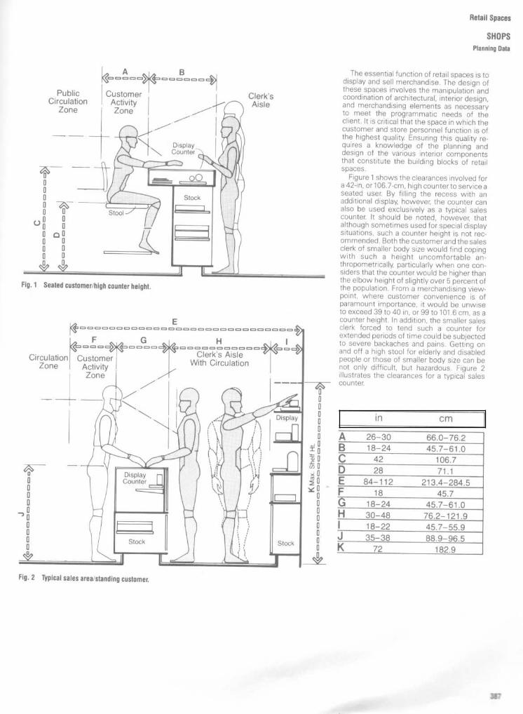
Retail Spaces
SHOPSPlanning Data
The essential function of retail spaces is todisplay and sell merchandise . The design ofthese spaces involves the manipulation andcoordination of architectural, interior design,and merchandising elements as necessaryto meet the programmatic needs of theclient . It is critical that the space in which thecustomer and store personnel function is ofthe highest quality. Ensuring this quality re-quires a knowledge of the planning anddesign of the various interior componentsthat constitute the building blocks of retailspaces .
Figure 1 shows the clearances involved fora 42-in, or 106 .7-cm, high counter to service aseated user. By filling the recess with anadditional display, however, the counter canalso be used exclusively as a typical salescounter. It should be noted, however, thatalthough sometimes used for special displaysituations, such a counter height is not rec-ommended . Both the customerand the salesclerk of smaller body size would find copingwith such a height uncomfortable an-thropometrically, particularly when one con-siders that the counter would be higher thanthe elbow height of slightly over 5 percent ofthe population . From a merchandising view-point, where customer convenience is ofparamount importance, it would be unwiseto exceed 39 to 40 in, or 99 to 101 .6 cm, as acounter height . In addition, the smaller salesclerk forced to tend such a counter forextended periods of time could be subjectedto severe backaches and pains . Getting onand off a high stool for elderly and disabledpeople or those of smaller body size can benot only difficult, but hazardous . Figure 2illustrates the clearances for a typical salescounter.
in cm
26-30 66.0-76.218-24 45.7-61 .0
C 42 106.728
71 .184-112 213.4-284.5
18
45.718-24 45.7-61 .0
H 30-48 76.2-121 .918-22 45.7-55.935-38 88 .9-96.572
182.9

Retail Spaces
SHOPS,Planning Data
Figure 3 shows the clearances required fora medium height display counter. The sug-gested seat height of 21 to 22 in, or 53 .3 to55.8 cm, requires a footrest for the seatedcustomer. The counter height shown willallow the display to be viewed by both theseated customer and the standing salesclerk . The customer activity zone allowsadequate space for the chair. Knee height,buttock-knee length, popliteal height, andeye height sitting are all significant humandimensions to consider in the design ofcounters to be used by a seated customer.
Figure 4 shows a low 30-in, or 76.2-cm,display counter also for use by a seatedcustomer. The anthropometric considera-tions are the same . Although the counterheight is responsive to the anthropometricrequirements of the seated customer, it isless than ideal for the standing clerk . For thestanding user's optimum comfort, the coun-ter height should be about 2 or 3 in, or 5 to 7.6cm, below elbow height . This will allow aperson to handle objects comfortably on thecounter surface or use the counter as sup-port for his or her arms . The 30-in height istoo low to permit such use .
in cm36
91 .426-30 66.0-76.2
C 18-24 45.7-61 .030 min .
76.2 min .10
25.421-22 53 .3-55 .9
G 5
12.723-25 58.4-63.54-6 10.2-15.2
J 34-36 86.4-91 .4K 30 76.2L 16-17 40.6-43.2
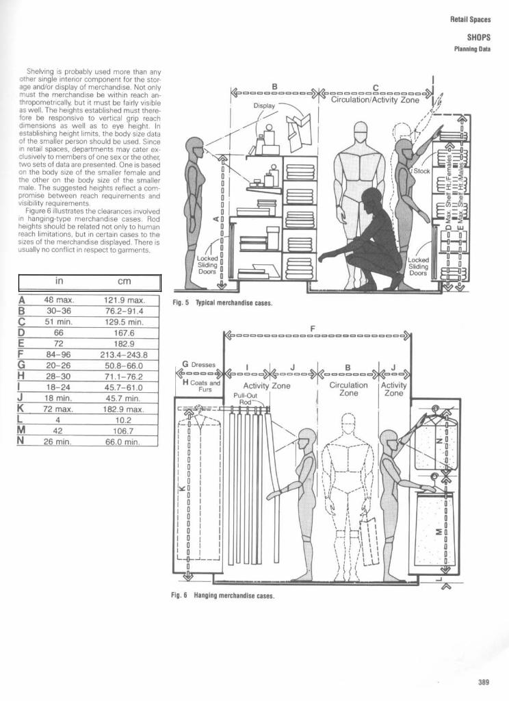
Shelving is probably used more than anyother single interior component for the stor-age and/or display of merchandise . Not onlymust the merchandise be within reach an-thropometrically, but it must be fairly visibleas well . The heights established must there-fore be responsive to vertical grip reachdimensions as well as to eye height . Inestablishing height limits, the body size dataof the smaller person should be used . Sincein retail spaces, departments may cater ex-clusively to members of one sex or the other,two sets of data are presented . One is basedon the body size of the smaller female andthe other on the body size of the smallermale . The suggested heights reflect a com-promise between reach requirements andvisibility requirements .
Figure 6 illustrates the clearances involvedin hanging-type merchandise cases . Rodheights should be related not only to humanreach limitations, but in certain cases to thesizes of the merchandise displayed . There isusually no conflict in respect to garments .
in cm
48 max .
121 .9 max .30-36 76.2-91 .4
C
51 min .
129.5 min .D 66 167 .6
72 182.984-96 213.4-243.8
G 20-26 50.8-66.028-30 71 .1-76.218-24 45.7-61 .018 min .
45.7 min .72 max .
182 .9 max .L 4
10.2M 42 106.7N
26 min .
66.0 min .
Retail Spaces
SHOPSPlanning Data
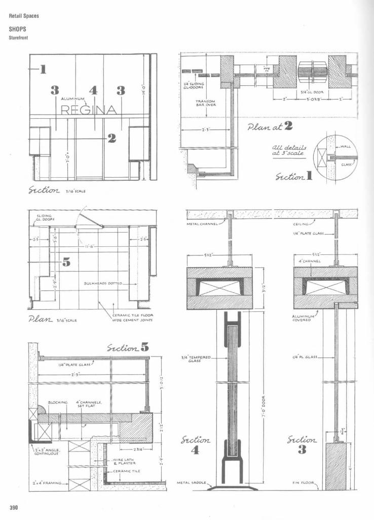
Ret II Sraces
SHOPSStorefront
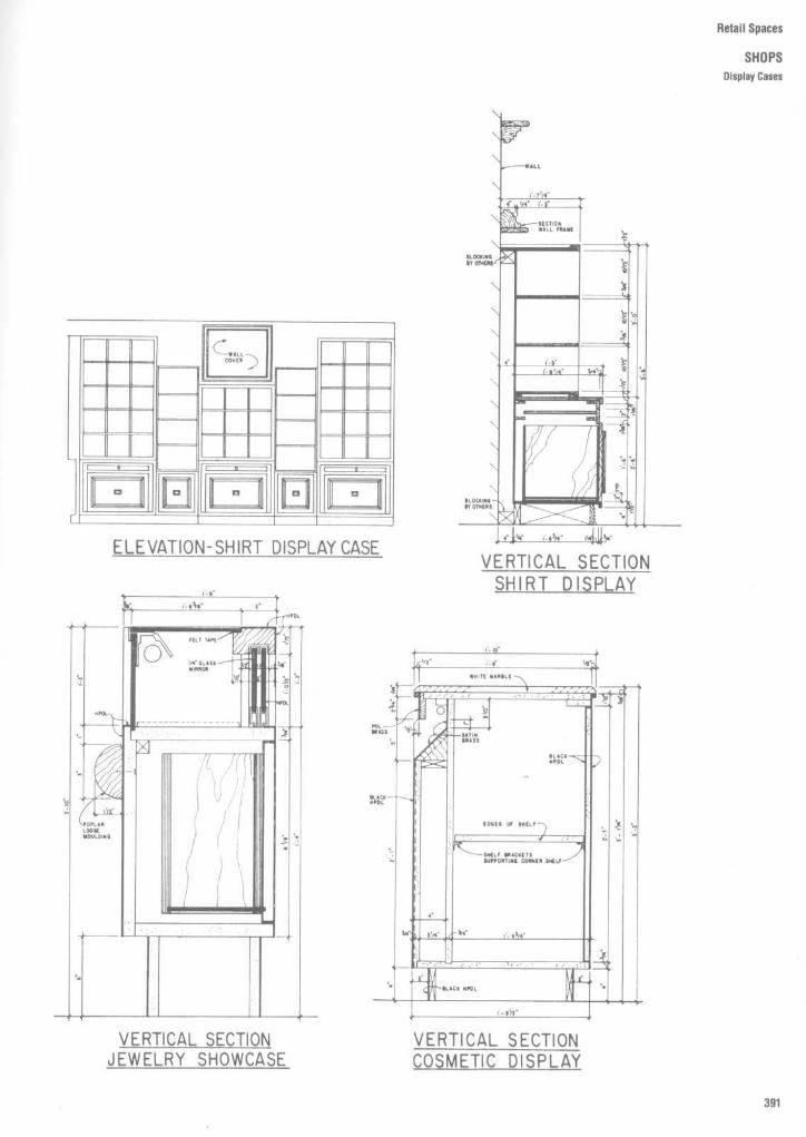
Retail Spaces
SHOPSDisplay Cases

Retail Spaces
SHOPS01splay Cases

Retail Spaces
SHOPS
Display Cases

Retail Spaces
SHOPS
Sales Counter

Retail Spaces
SHOPSCounter Details

Retail Spaces
BANKS
Teller's Counter

Retail Spaces
BANKSTeller's Counter

Retail Spaces
BANKSTeller's Counter

Retail Spaces
BANKSCheck S9ands

Retail Spaces
BANKSCounter

Retail Spaces
DEPARTMENT STORESFashion and Fine Jewelry Back Island Details

Recall Spaces
DEPARTMENT STORESShowcase for Men's Cosmetics and Fragrances

Retail Spaces
DEPARTMENT STORESShowcase for Men's Cosmetics and Fragrances
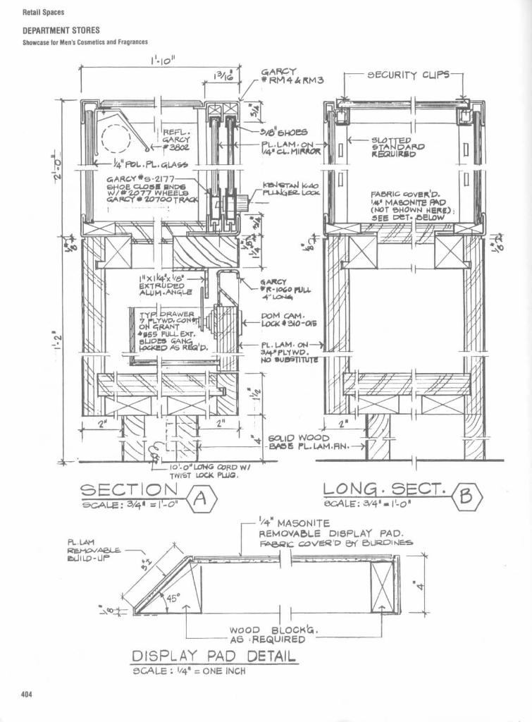
Retail Spaces
DEPARTMENT STORESShowcase for Men's Cosmetics and Fragrances

Retail Spaces
DEPARTMENT STORESTelevision Cabinet Details

Retail Spaces
DEPARTMENT STORESTelevision Cabinet Details

Retail Spaces
DEPARTMENT STORESShelving Details

Retail Spaces
DEPARTMENT STORESShelving Details

Retail Spaces
DEPARTMENT STORESShelving Details
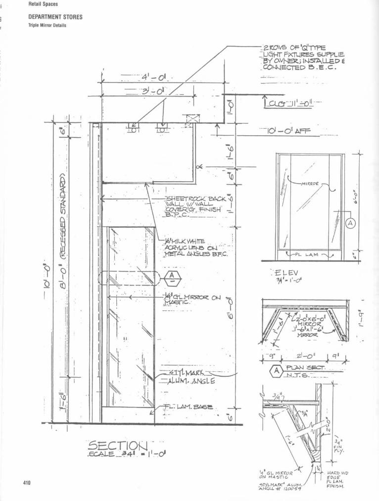
Retail Spaces
DEPARTMENT STORESTriple Mirror Details

Retail Spaces
DEPARTMENT STORESBack-Lighted Transparency Display

Retail Spaces
DEPARTMENT STORESFeature Wall Lighting

Retail Spaces
DEPARTMENT STORESFeature Wall Lighting
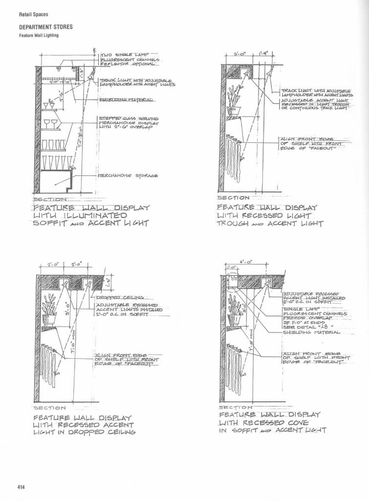
Retail Spaces
DEPARTMENT STORESFeature Wall Lighting

Retail Spaces
DEPARTMENT STORESValence and Cove Lighting Details

Retail Spaces
DEPARTMENT STORESValence and Cove Lighting Details

Retail Spaces
DEPARTMENT STORESValence and Cove Lighting Details

Retail Spaces
DEPARTMENT STORESWall Display Systems

Retail Spaces
DEPARTMENT STORESWall Display Systems
-Design continuityfrom wall to floorcarries theme throughoutthe department orthe store-Designed for highvolume merchandising
-Flexible merchandising-Designed to becompatible with otherPam International Systems
" All Multiples/Systems 2TM upright posts are engineered with easily changeable post covers (Pat . Pend.)" All metal components are coated with a durable, long lasting, baked on epoxy powder finish .

Retail Spaces
DEPARTMENT STORESRack Display Systems

Retail Spaces
DEPARTMENT STORESRack Display Systems

Retail Spaces
DEPARTMENT STORESDisplay Systems Standards

.u
~c
es rooms
o~ e s an
-oa roomsRestrooms and toilets
425Coatrooms
460


Public Restrooms, Toilets, and Coatrooms
RESTROOMSANDTOILETSPlumbing Data
IYLE 1
Minimum Number of Plumbing Fixtures Required by B uilding O ccupancy Type'
'The population used in determining the number of fixtures required shall be based on the number of people to occupy the space but in no case shall the population be less than that determined by allowing 125 sq. ft. of net floor areaper person .(Such facilities may be in adjacent buildings under the same ownership or control, and shall be accessible during periods when the assembly space is occupied.(Facilities for employees in a storage building or warehouse may be located in an adjacent building, under the same ownership, where the maximum distance of travel from the working space to the toilet facilities does not exceed
500 ft. horizontally.
Type of type or fixture
building Bathtubs or Drinking Otheroccupancy Water closets Urinals Lavatories showers fountains fixtures
-places of 1 far ea . sex for ea. 150 Urinals may be provided in~Q~pt persons toilet rooms in lieu of water
closets but for not more than 11/2 of the required number of
water closetsUse
only-other than places No. of No of fixtures Urinals may be provided in No. of No . of 1 for ea . 1,000 persons Where motion picture pro-31'worship (including but not persons for each sex toilet rooms in lieu of water persons fixtures except that there shall be at jection booths contain moreünted to auditoriums, 1-100 1 closets but for not more than 1-200 1 least 1 fixture at each than 2 projectors, at least 11sixers, convention hallsl 101-200 2 1/2 of the required number of 201-400 2 assembly floor level or tier water closet and 1 lavatorya¢ ale spaces classified 201-300 3 water closets 401-750 3 shall be provided on the samea "d 301-400 4 Over 750, add 1 fixture for ea . level and within 20 ft . of the
Over 400, add 1 fixture for ea . 500 persons boothsex for ea. additional 200persons
)&~nories - school or labor, 1 for ea sex for ea 8 persons Urinals may he provided in 1 for ea. 12 persons 1 for ea 8 persons, far Laundry trays- 1 for ea 50yin institutional toilet rooms in lieu of water women's dormitories, 1 persons
closets but for not more than bathtub shall be substituted1/2 of the required number of for 1 shower at the ratio of 1water closets for ea . 30 women
Single room occupancies for 1 for ea . 6 persons 1 for ea . 6 persons 1 for ea . 6 personsseeping accommodations7"Y
]wellings - one- and 1 for each dwelling unit 1 for each dwelling unit 1 for each dwelling unit Kitchen sink-1 for eachvim-family dwelling unit
°.folic buildings, offices, No . of Urinals may he provided in No . of No, of 1 for ea . 75 personsaainess mercantile, storage, persons No of toilet rooms in lieu of water persons fixturesrarehouses,factories and each sex fixtures closets but for not more than 1-20 1nstdutional employeest 1-15 1 1/2 of the required number of 21-40 2
16-35 2 water closets when more 41-60 336-55 3 than 35 persons 61-90 456-80 4 91-125 581-110 5 1 fixture for ea . additional 45111-150 6 persons
1 fixture for ea . additional 40persons
Public bathing 1 fixture for ea. sex for ea . Urinals may be provided in30 persons toilet rooms in lieu of water
closets but for not more than 1/60 1/401/2 of the required number of
water closets
Schools : 1 fixture for ear- sex for ea . Urinals may he provided in In gym or pool shower roams, 1/50 persons but at least 1Elementary 35 students toilet rooms in lieu of water 1/50 pupils 1/3 pupils of a largest class per floorSecondary closets but for not more than 1/50 pupils using pool at any one time
1/2 of the required number of Over 300 pupils . 1 /100 pupilswater closets
Workers' portable facilities 1/30 workers 1/30 workers At least 1 per floor equivalentfor ea. 100 workmen
Industrial -foundries only No. of No . of Where more than 10 men are No. of No. of 1 shower for each 15 persons 1 for ea . 75 personspersons fixtures employed. persons fixtures exposed to excessive heat or1-10 1 No . of No . of 1-8 1 occupational hazard from11-25 2 men urinals 9-16 2 poisonous, infectious, or26-50 3 11-29 1 17-30 3 irritating material51-80 4 30-79 2 31-45 481-125 5 1 additional fixture far each 46-65 51 additional fixture for each additional 80 males 1 additional fixture for eachadditional 45 persons Urinals may be provided in additional 25 persons
toilet rooms in lieu of waterclosets but for not more than1/2 of the required number ofwater closets
Other fixtures
Kitchens for public or 1 lavatory for the personal One machine or a 3-compartment sink for the effectiveemployees dining use of kitchen employees washing and sanitizing of all cutlery, dishes and glasses
before re-use
Dwellings -multiple or 1 for each dwelling unit or 1 for each dwelling unit or 1 for each dwelling unit or Kitchen sink- 1 for each dwelling unit or apartment. Withinapartment apartment apartment apartment each dwelling unit, not designed for use by transients, one
laundry tray or automatic laundry washing machine : or in areadily accessible location within a general laundry room .1 two-compartment tray for each 10 dwelling units or 1automatic laundry washing machine for each 20 dwellingunits

Public Restrooms, Toilets, and Coatrooms
RESTROOMS AND TOILETS
Plumbing Fixture and Accessory Heights
While Fig . 1 provides specific vertical di-mensions of both plumbing fixtures andaccessories, the designer is cautioned thatevery plumbing fixture and accessory mustbe carefully analyzed in light of the users tobe served . Plumbing contractors will followthe manufacturer's recommendations ortheir own standards unless the designerprovides this information on the workingdrawings . In large-scale projects, it is sug-gested that the designer carefully provide allfixture mounting heights on all interior eleva-tions or on a separate diagramatic drawing,such as is shown in Fig. 1 .
TOILET UQINAL
HANDICAP TOILET STALL
Fig. 1
Fixture heights .
Handicapped Washrooms
Fig . 2
Suggested mounting heights for various bathroom accessories.
LAVATOQY
TOWEL vl5PF_u5e¢/WASTE PECEPTACLE
M10202/TOWEL MiRRORITOWEL4D15PEH5EIZ
SOAP DI5PCU5ER
SANITAQY NAPKIuVENDOIL
Partition Mounted Units
Fig. 3 Typical back to back male/female washroom stalls usingpartition mounted units to accommodate a handicapped stall and onestandard stall . If room permits, grab bars should be placed on all threesides, resulting in a "U"-shaped configuration . Most codes requiretoilet stall doors to open outward.

Public Restrooms, Toilets, and Coatrooms
RESTROOMS AND TOILETS
Plumbing Fixture and Accessory Heights
Fig . 4
This drawing of a part plan and part elevation of a men's toilet room demonstrates how mounting heights of plumbing fixtures andaccessories are indicated . In addition, spacing of plumbing fixtures is indicated by use of a horizontal dimension from centerline to centerlineof the lavatories . Many designers prefer to show horizontal dimensions on the plan . a=recessed waste receptacle, b=recessed toweldispenser and soap dispenser with shelf.
PART EL EVATI ON
PART PLANM E N'S
TOI LET
R0 o M

Public Restrooms, Toilets, and Coatrooms
RESTROOMS AND TOILETSPlumbing Fixture and Accessory Heights
Fig. 5
Mounting heights or vertical dimensions are always taken from the finished floor. When installing accessories on tile walls, the tile module anddimensions should be taken into consideration . a=full length mirror, b =recessed feminine napkin dispenser, c= recessed towel cabinet and waste receptacle,d= recessed soap dispenser with shelf.
PART ELEVATIION,PA R T
E L E VAT ION
PA RT
PL A N PA RT P L A N
W O M E N S
T O I L E TR O O M,

Public Restrooms, Toilets, and Coatrooms
RESTROOMS AND TOILETS
Plumbing Fixture and Accessory Heights
Fig. 6
The mounting heights of plumbing fixtures and accessories for a private toiletare, in many instances, determined by the physical characteristics of the primary user.A person 6'6" tall might require the mounting height of a lavatory, mirror, or showerhead to be higher than usual. Note that any electrical outlets near a lavatory or showermust be specified with a ground fault interrupter. c= first aid cabinet and medicinecabinet .
PART ELEVATION
PA KTPLANPRI VAT E
TOI LET
ROOM

Public Restrooms, Toilets, and Coatrooms
RESTROOMS AND TOILETSPlans
SIDE ENTRANCEWHEEL CHAIRTOILET ENCLOSURE
This Is not preferred)
MEN
WOMEN
Fig . 7
These drawings show minimum dimensions both for toilet enclosures and between partitions and walls . These layouts are recommendations providedby the General Services Administration, but they may not be in conformity with other codes or desired bathroom layouts, especially in regard to accessibility.Remember, too, that codes provide minimum, not optimal, standards .

Public Restrooms, Toilets, and Coatrooms
RESTROOMS AND TOILETS
Plans and Elevations
Fig . 8
These working drawings provide both vertical and horizontal dimensions for placement of plumbing fixtures and accessories . Note that accessories areidentified or "called out" through the use of letters, which would be coordinated with either a legend or a schedule .
L AVATO RY
LAVATORY
JAN GLOS)RT

Public Restrooms, Toilets, and Coatrooms
RESTROOMS AND TOILETSPlans
In multiple-fixtured public toilets, at leastone watercloset and lavatory must be de-signed to conform to barrier-free or ac-cessibility standards .
JAN . ~ivs T
RY
L AVATO RY
RY

Public Restrooms, Toilets, and Coatrooms
RESTROOMS AND TOILETS
Plans and Elevations
M A E a NSTO i LET

Public Restrooms, Toilets, and Coatrooms
RESTROOMS AND TOILETSPlans and Elevations
The women's room shown in Fig. 9 re-quires approximately 250 ft2 for the toiletarea and about the same for the vanity area .Wall elevations for the two areas are shownin Fig. 10 . The designer should carefullyanalyze the number of lavatories and water-closets specified fora given facility. Researchsuggests that most "fixture counts" pro-
vided by city or state codes are too low anddo not adequately reflect the amount of timethat women require. As a result, it is notunusual to see long lines in front of women'srooms, particularly those that service placesof public assembly. Note thatthe plan in Fig. 9provides supplemental vanity or countersurfaces .
P
T > E R r-O y MFig . 9

Public Restrooms, Toilets, and Coatrooms
RESTROOMS AND TOILETSPlans and Elevations
Fig .10
Wall elevations for the women's room plan in Fig . 9 .

Public Restrooms, Toilets, and Coatrooms
RESTROOMS AND TOILETSPlans and Elevations
436
Fig. 12
Wall elevations for the men's room and women's room complex shown in Fig . 11 .
WOME NS TOILETMN S . TO I LET r:.Fig.11
This men's room and women'sroom complex, including a janitor's closet, requires slightly more than 400It' of floor area .Corresponding wall elevations are shown in Fig. 12 .

Public Restrooms, Toilets, and Coatrooms
RESTROOMS AND TOILETSPlans and Elevations
Fig . 12
(Continued)

Public Restrooms, Toilets, and Coatrooms
RESTROOMS AND TOILETS
Miscellaneous Elevations
Fig . 13
These drawings show how some designers indicate the heights of certain fixtures and bathroom accessories .

Public Restrooms, Toilets, and Coatrooms
RESTROOMS AND TOILETS
Miscellaneous Elevations

Public Restrooms, Toilets, and Coatrooms
RESTROOMSAND TOILETS
Plans and Elevations
men's toilet

Public Restrooms, Toilets, and Coatrooms
RESTROOMS AND TOILETSPlans and Elevations
TOi LET ROOM ELEVAT IONSFig . 14
Detailed large-scale wall elevations such as this are required to show materials, accessory mounting heights, the coordination andPlacement of plumbing fixtures, and even manufacturer's model numbers.
1 1 ,
Fig. 15
The large-scale counter detail shown here provides all the information needed to constructthis essential bathroom element. Not only are the construction details carefully defined anddescribed, but all the other design relationships are clearly shown . Note the relationships of themirror, soap dispenser, and lavatory to the plastic laminate counter. Other lavatory counter detailsare shown in Figs . 16 to 19 .
II COUN R ~Irlilt,
9= ILo+

Public Restrooms, Toilets, and Coatrooms
RESTROOMS AND TOILETSLavatory Counter Details
SECTION
TOILET LAVATORYIYP
:JCGT./DCfIJLSILO LAATORIES
SEGTION - LAV. COUNTER

Public Restrooms, Toilets, and Coatrooms
RESTROOMS AND TOILETSLavatory Counter Details
COUNTER DETAILS~tya ° s l' - o"
LAVATORY

Public Restrooms, Toilets, and Coatrooms
RESTROOMS AND TOILETSLavatory Counter Details
L n LAVATORY COUNTER5
DETAIL @LAVATORY
TAI

RESTROOMS AND TOILETSLavatory Counter Details
Public Restrooms, Toilets, and Coatrooms
VATION @ VANITY_RMS_110 112 0
va.N I TY -DETAIL L,
ô Cabinet

Public Restrooms, Toilets, and Coatrooms
RESTROOMS AND TOILETS
Lavatory Cabinet Details
Fig . 20
Elegantly detailed lavatory cabinets are shown here . Note the use of an exposed oil-finished red mahoganyframe or edge surrounding a verdi antiquemarble top. Complementary telephone shelf details in plan, elevation, and large-scale detail are also shown .
,i
CIt.ÂWET DETNL ei RDWGEIZ K
1\'~J4c~ : ,k' " ,~p'
P.,v,f4ü-1 C^B04ET
C~C~r~T DETAIL at WOMEN
ie PLAN ELEV + SECT oF 5meà-Fif 7tLaek>IE NY-K
~1 F~,él(a/ S SG~1 oi sriF.i.f iwn1Er~^21
3CSy,E i4' ~ isd

Public Restrooms, Toilets, and Coatrooms
RESTROOMS AND TOILETS
Toilet Stall Details
PLAN
FRONT ELEVATIONSIDE ELEVATIONFRONT ELEVATION
SECTION D-DE-E
SECTION A-A E-E
OUTSWING DOOR INSWING DOOR
CEILING FASTENINGSECTION B'BSIDE VIEW
SECTION C-C

Public Restrooms, Toilets, and Coatrooms
RESTROOMS AND TOILETSToilet Stall Details
PLANPLAN
FRONT ELEVATIONSIDE ELEVATIONFRONT ELEVATION
E-EINSWING DOOR
SECTION D-DOUTSWING DOOR
E-ESECTION A-A
FLOOR FASTENINGSECTION B-0
SIDE VIEW(SECTION)
Fig . 22

Public Restrooms, Toilets, and Coatrooms
RESTROOMS AND TOILETSWheelchair Accessible Desian
TOILET AND RESTROOM DESIGNThe design data contained on the followingpages are intended to illustrate functionalaccessibility concepts . Some examples illus-trate minimum federal requirements, whileothers are culled from among the variousstate standards . Designers are cautioned toconsult local standards in their respectivejurisdictions .The current minimum federal standard is
ANSI A117.1-1986, published by the Ameri-can National Standards Institute, Inc . It spec-ifies a stall typified by detail a/3 . This "fronttransfer" type stall requires a waterclosetmounted at 1'8" a .f.f., preferably wall hung .Stall doors must be outswinging .Because a significant portion of people
using wheelchairs cannot transfer in thismanner, the side transfer stall (b/3) has beendeveloped . Clear stall dimensions and seatheights vary somewhat with jurisdiction .Most standards that address side transferstalls require lower seat heights with 15"-17"mounting heights being typical .We recommend locking devices for doors
that do not require twisting and graspingmotions, avoidance of foot operated flushvalves, installation of ceiling or wall-hungpartitions as practical, and avoidance of cur-tains in lieu of doors .
Federal standards mandate grab bars of1 1/2 " o.d . The bars must be securely mounted1%z" clear from the wall or partition . Thismounting distance is critical, as it provides a"cradle" for a forearm during transfer or if auser loses her or his grip.
side_transferscale. 3/8"= T-0"
3front transfer a- ale: 3/8"= 1'- 0�
side elevationscale: 3/8"=1'-
0-front transfer
~)scale: 3/8"=1'-0"
sectionscale 3/8"=1'-0 4grab bars ,
scale : half

Public Restrooms, Toilets, and Coatrooms
RESTROOMS AND TOILETSWheelchair Accessible Design
Lavatories need not be specialized designsto be accessible . Utilization of clearancesshown will do much to make lavatoriesaccessible . Because persons with loss ofsensation in their legs cannot feel pain (andbecause they heal at a slower rate), hotwaterlines and drains must be insulated . Also,under several state codes, faucets are re-quired to be lever, blade, or multi-arm handleoperated .
Single lever controls are preferable .Spring-operated faucets must have time de-lay devices .At least one mirror must be located with
the reflecting surface mounted at 3'4" a .f.f.(3'2" or lower preferable) . Where possible,full-length mirrors are preferable .At least one of each type of toilet acces-
sory must also be located at 3'4" a .f .f. or less .Note that this dimension is measured to thehighest control required for operation . Con-trols that require twisting and grasping mo-tions should be avoided .Because people that use wheelchairs re-
quire increased fluid intake, drinking foun-tains become more than convenience items .While there is not space here to address allconfigurations, the following concerns aretypical to all : controls should be operablewithout the need for precise grasping ; thefaucet should not direct spray away from theuser and must be located as near the frontedge as practical ; the units must be free ofsharp edges and corners and overheadobstructions .
lavatoryscale 3/8"=1'-0"
lavatory, scale : 3/8"=1'-0"
I
,3mirrors
G3
accessory_scale : 3/8"= 1'-0"
d.f. _scale.1/4"=1-0"
alcove uscale 1/4"=t'-0"
3e.w c.
3
alcovescale : 1/4"=1'-0"
1)d.f.scale 1/4=1-0"3~

Public Restrooms, Toilets, and Coatrooms
RESTROOMS AND TOILETS
Wheelchair Accessible Design
Urinals, if provided, should have elongatedbowls with the opening of the basin locatedat 19" a.f.f. or less, or mounted level with themain floor. Many state standards specifymaximum mounting heights of 15"-16" a.f.f.These lower dimensions are preferable .The toilet room itself should provide a clear
floor area with minimum dimensions of 60" x60" to facilitate maneuvering wheelchairs .Additionally, provide a minimum of 3'6" clear-ance in front of accessible toilet stalls tofacilitate entry.
Similarly, adequate clearances must beprovided at entrances . The spaces shown indetails 113 to o/3 represent typical dimensionsspecified in state codes. Note, however, thatfederal and many state standards require 12"clear jamb areas adjoining both sides of alldoors. A clearance of 18" or more on thestrike side of a door is more effective. Investibules having doors in series, there mustbe space for a wheelchair to clear one doorprior to opening another.
urinal 93
urinal----scale: 3/8"=1'-0"
3urinalscale 3/8"=1'-0"
clear. k~scale: 1/8"=1'-0"
clearances_ale : 1/8"=1'-0"
- -_-.
3
clearances mscale 1/4"=1'-0"
-3)
clearancesscale: 1/4"=1'-0"
3
clearances Y 0-scale 1/4"=1'-0
` . 3,~clearances -scale : 1/4"=1'-0"
3

Public Restrooms, Toilets, and Coatrooms
RESTROOMS AND TOILETSWheelchair Accessible Design
(a)Standard Stall
(a-1)Standard Stall (end ofrow)
(c)Rear Wall of Standard Stall
(d)Side Walls
(b)Alternate Stalls
Fig. 23
Toilet stalls .
42 min latchapproach onigother approaches48 min
42 min latchapproach only,other approaches48 min

r Figs . 24 to 30, various generic toiletacxssories and grab bar configurations areilustrated . While most manufacturers havesrnQr accessories and grab bars within their:ra+ogs, overall dimensions and methods of
installation vary greatly. Placement of ac-cessories in relationship to plumbing fix-tures, door swings, and interior circulation isto be carefully studied by the designer.
Fwial tissuedispenser
Dal feminine napkin/tapon vendor
"all urn ash tray
-.quid soapi spenser
All-purpose unitwith concealedtowel cabinet
Dual feminine napkin/tampon vendor
Sanitary napkin disposal
Recessed powderedsoap dispenser
Multipurpose unit with mirror, shelf,towel, and liquid soap dispensers
Sanitary napkin disposal
Recessed dual napkin/tampondispenser and disposal
Toilet seat cover dispenser
Recessed horizontalsoap dispenser and shelf
Disposal valvesoap gun
Public Restrooms, Toilets, and Coatrooms
RESTROOMS AND TOILETSToilet Accessories
Recessed seat cover andtoilet tissue dispenser

Public Restrooms, Toilets, and Coatrooms
RESTROOMS AND TOILETSToilet Accessories
Paper towel dispenser Paper towel dispenser Paper towel dispenserand disposal
Paper towel dispenser Paper towel dispenser
Paper towel disposalPaper towel disposal
Towel dispenser andDisposa-Valve soap gun
Paper towel disposal
Paper toweldispenser anddisposal
Roll paper toweldispenser anddisposal
Paper toweldispenser anddisposal
Paper toweldispenser andcovered disposal
Paper toweldispenser anddisposal
Semirecessed waste receptaclePaper toweldispenserand disposal
Roll paper towel dispenserand disposal

Public Restrooms, Toilets, and Coatrooms
RESTROOMS AND TOILETSToilet Accessories
so tlrrys
irsste receptacles
yaelves
Medicine cabinets

Public Restrooms, Toilets, and Coatrooms
RESTROOMS AND TOILETSToilet Accessories
Sanitary napkin dispensers Sanitary napkin disposals
Hand and hair dryersCombined sanitary napkin dispenser and disposal
Paper cup disposalPaper cup dispenser
Multipurpose cabinet
Fig . 2 7

Soap dispensers
Hill . 28
Prper towel dispensers
tiiet tissue dispensers
Public Restrooms, Toilets, and Coatrooms
RESTROOMS AND TOILETSToilet Accessories

Fig . 29
left hand shownright hand opp . right hand shown
left hand opp . right hand shownleft hand opp,
bar swings full leo°
bft hwtd showntight hand opp.
left hand shownright hand opp.
Idf hand shownright hand opp .
Public Restrooms, Toilets, and Coatrooms
RESTROOMS AND TOILETSGrab Bar Configuralions
Projects 3" below finished floor,has slip flange at floor.
'This dimension 11" when11/z" O.D. tubing specified .'This dimension 11" when111/2" O.D. tubing specified .

Public Restrooms, Toilets, and Coatrooms
RESTROOMSAND TOILETS
Grab Bar Configurations
right hand shownleft hand opp.
right hand shownleft hand opp.
right hand showntell hand opp.
right hand shownleft hand opp.
-gnt hand showneft hand opp.
right hand shownleft hand opp .
right hand shownleft hand opp.
right hand shownleft hand opp.36" from side wall to side wall
Fig . 3 0

Public Restrooms, Toilets, and Coatrooms
COATROOMS
Floor Area Requirements
Coatrooms typically fall into two catego-ries : those that are self-service and thosethat are controlled by one or more atten-dants . The latter category of coatroom can bemore compact because only one, or perhapstwo, attendants have access to the coats. Aself-service coatroom must have more spacebetween rows of coats so that several per-sons can enter and get their coats.
Self-service coatrooms are susceptible totheft of property, particularly expensive out-erwear Therefore, it is desirable that thesecoatrooms be visible to someone at all times,such as a maitre d' in a restaurant or areceptionist in an office. In those situationswhere a supervised self-service coatroom isinappropriate or cannot be provided, self-service keyed locks offer a viable alternative .In addition to being able to provide securecoat storage, lockers can also store brief-cases, packages, or other encumbrances .
TABLE 1
Floor Area Requirements for Public Coatrooms
Note : The above floor areas are approximate and should only be used for preliminary spaceplanning requirements .
Since the number of coats per linear foot of hanging can vary from 4 to 8, the floor area can varydramatically. A lightweight overcoat, for example, can measure 1-1 .5 inches in width. A mediumweight to heavyweight coat might measure from 2 to 4 inches . A fur coat might require a minimumof 4-6 in . The designer must consider the overall size of coatroom based upon the following criticalfactors : (1) geographic location/climate ; (2) attendants required or not required ; (3) aisle clearance;(4) peak entry/exit loads for coat retrieval ; (5) assumed garment thickness or garments per linearfoot ; (6) linear feet of counter surface and overhead shelving ; and (7) other storagecomponents, i .e .,hats, umbrellas, briefcases, packages, etc.
Number of coats(capacity)
Floor area(with attendant)
Min MaxFloor area
(without attendant)Floor area
(elect ric conveyor)
50 35 50 40 60 N/A N/A100 65 85 80 100 80 100150 90 120 110 145 110 125200 125 150 150 180 140 150250 150 190 180 230 100 110300 180 225 215 270 125 140350 200 260 240 300 135 150400 225 275 270 330 150 160450 260 320 310 370 160 175500 300 365 425 430 175 190750 450 500 540 600 250 275
1000 600 650 720 780 325 3501500 800 900 950 1080 450 4802000 1000 1250 1200 1500 600 6753000 1600 1850 1900 2200 1000 1150
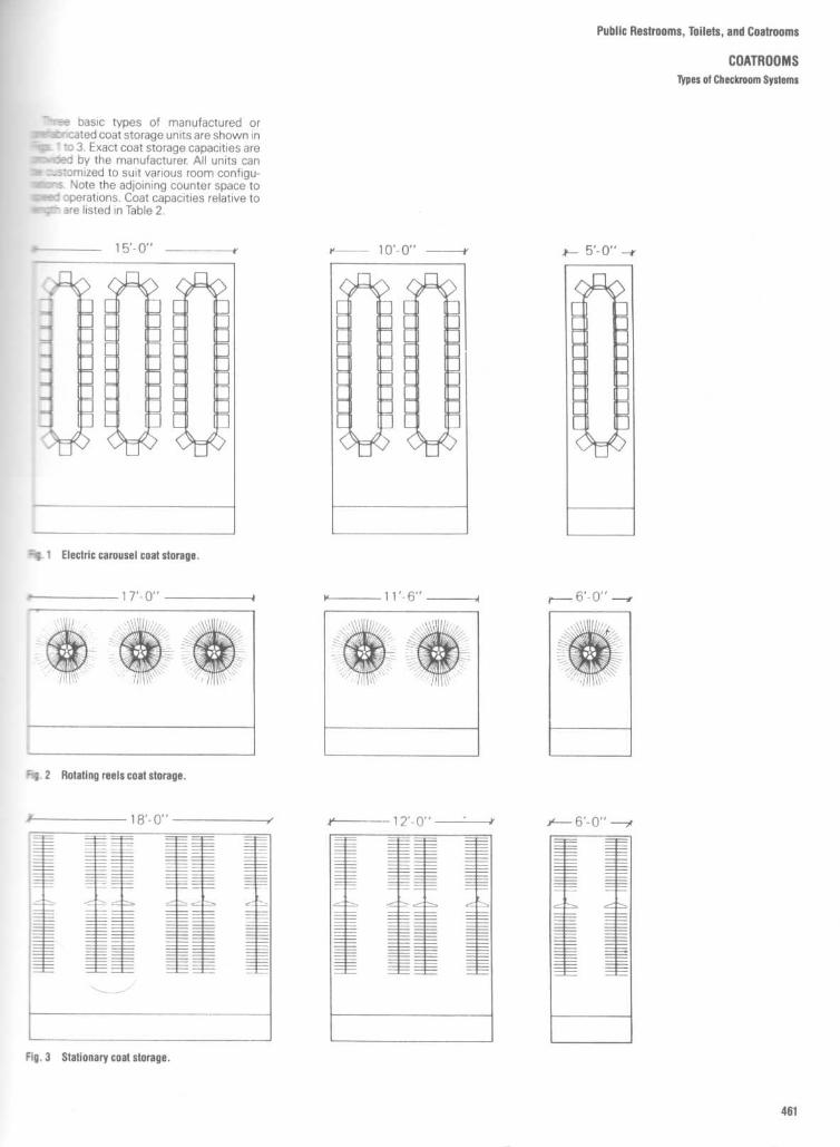
Public Restrooms, Toilets, and Coatrooms
COATROOMS
typesof Checkroom Systems
"r- basic types of manufactured orserc , zated coat storage units are shown inFmw ' 'o 3. Exact coat storage capacities aremwoed by the manufacturer. All units cans :.stomized to suit various room configu-aa^s Note the adjoining counter space to
operations . Coat capacities relative to~
- are listed in Table 2 .
=q 1
Electric carousel coat storage .
^q . 2
Rotating reels coat storage .
Fig . 3
Stationary coal storage .

*Add 4" minimum clearance to each end andeach side when adjacent to walls, columns,obstructions, or other machines .
tThis provides 1 .1" per coat . In areas orfacilities where bulky coats are customary, theactual capacity maybe reduced one-third .
Public Restrooms, Toilets, and Coatrooms
COATROOMS
Electric Checkroom Systems
TABLE 2
Overalllengthwith
garments*
Lengthof
hangingcapacity
Coatcapacity :
no. of slotst
7' 5" 13' 0" 144
7'11 112" 14' 1 " 1568' 6" 15' 2" 1689' ill 16' 3" 1809' 7" 17' 4" 19210' 1 1/2" 18' 5" 20410' 8" 19' 6" 21611' 21/2" 20' 7" 22811' 9" 21' 8" 24012' 31/2" 22' 9" 252
12'10" 23'l 0" 26413' 41/2" 24'11" 27613'11" 26' 0" 28814' 5112" 27' 1" 30015' 0" 28' 2" 31215' 61/2" 29' 3" 32416' 1" 30' 4" 33616' 71/2" 31' 5" 34817' 2" 32' 6" 36017' 81/2" 33' 7" 37218' 3" 34' 8" 38418' 9'12" 35' 9" 39619' 4" 36'10" 40819'110 1/2" 37'11" 42020' 5" 39' 0" 432
20'l 1 1/2" 40' 1 " 44421' 6" 41' 2" 45622' 01/2" 42' 3" 46822' 7" 43' 4" 48023' 1 1/2" 44' 5" 49223' 8" 45' 6" 50424' 21/2" 46' 7" 51624' 9" 47' 8" 52825' 31/2" 48' 9" 54025' 10" 49'l 0" 55226' 41/2" 50 , 11" 56426'11" 52' 0" 576
27' 51/2" 53' 1" 58828' 0" 54' 2" 600

Public Restrooms, Toilets, and Coatrooms
COATROOMS
Stationary Checkroom Systems
Length I Numberof Coats of
NumberShelves
3'-0" 360
2
WallMounted 4'-0" . 48
5'-0" 60012
3'-4" 36012
Single 4'-4" 48 01
Face 25'-4rr 60
2
03
.-4" 72 12
DoubleFace
4'-4" 96 1
2
5'-4" 120 2
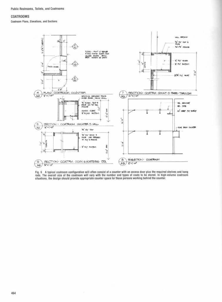
Public Restrooms, Toilets, and Coatrooms
COATROOMS
Coatroom Plans, Elevations, and Sections
tiYAQ - fNMr 6~ I w&*i1wo rof aqÇ% HKAI
& M40
~~9EL~loN= c~ttr~M . ax.Nr ~ fï~5 -?üfrollG~1FLAW n C.CaATFGGWi cct)4TaRyN . o
Fig . 6
A typical coatroom configuration will often consist of a counter with an access door plus the required shelves and hangrods . The overall size of the coatroom will vary with the number and types of coats to be stored . In high-volume coatroomsituations, the design should provide appropriate counter space far those persons working behind the counter.
~s1-~Ya x~l: oaa,>~- AG sl-n _!!FcnOf4 , COA77W . CON S POSTE-:156 'CIA
Pro If<"1-0
5
COGIlC7d + CnCrFk :tA OClhdfâ=S üK1.AG W " I
__ , .

Public Restrooms, Toilets, and Coatrooms
COATROOMSCoatroom Shelves Details
N0TYf~ - St=11rL 6N1Htt:T__tG-'.2 .' ~FOFL SoGHtt_MUl-'R_ -
-TYPICALOPEII COAï' At~ A
QPCAL~-AS Nt7TmO


Construction Detailsand FinishesPartitions and wall finishesFloors and floor finishesDoorsCeilingsStairsFireplacesLighting
469516566641660724743


Construction Details and Finishes
PARTITIONS AND WALL FINISHES
Selecting the appropriate partition or wall type is both a science and an art .r =act, there are so many options available to the designer that it is notjrisual to refer to the partition or wall as a system, a combination of framing,sreathing, and finish elements, all working together to meet aesthetic,-_- ctional, code, and economic requirements .
I
n that regard, this section explores the great variety of wall and partition. .Des, examining all of their characteristics with the exception of load bearingopacity and cost of labor and materials. With respect to load bearing ors*ructural capacities, while many of the wall and partition types are able tomrry superimposed loads, it is not the intent of this book to discuss structuralslues . With respect to cost, too many factors and variables make this a topicmat is difficult to analyze with any precision .
Information on both traditional and contemporary partitions and wall typess provided . Many traditional materials and methods of construction, such assolid gypsum plaster and plaster on clay tile, are cited, thus providinginformation to the designer who is redesigning or altering older structures .A large portion of this section is devoted to the detailing of contemporary
aartition systems. In addition to providing examples of partition types, theseSages place great emphasis on the detailing of unusual interface conditions;hat many designers often leave to the contractor to work out in the field . Itshould be noted that most, if not all, of these details have been selected from-.he working drawings of outstanding architectural and interior design firms .While general information has also been provided about acoustics, sound
-ransmission, and fire ratings of various walls and partitions, the designer iscautioned to verify all such information with manufacturers' certified testresults, as well as with those building and fire codes having jurisdiction . It alsoshould be noted that while test results maydemonstrate a certain fire rating orsound transmission classification, it is important to determine if the results-iave been accepted by the local building or fire department .
It is often necessary to apply a finish to a wall or partition . Again, bothtraditional and contemporary methods to apply wood paneling, ceramic tile,and stone are clearly illustrated through the use of architectural details .
Finally, walls and partitions must ultimately meet floors and ceilings, and, ofcourse, have doors and openings penetrate them . While some examples areprovided in this section, the designer will also find important information in thesections Floors and Floor Finishes ; Doors; and Ceilings, which follow.

Construction Details and Finishes
PARTITIONS AND WALL FINISHÉSCharacteristics of interior Partitions
DRAWING AND DESCRIPTIONSOIL AND
FIRE-RATING DAMAGE ACOUSTICS REMARKSRESISTANCE
COST COHPAPISON
4 Inch face brick, tooledjoints ;Actual thickness, Sibinches ;Weight, 40 IDs . per squarefoot of wall surface
4 inch concrete block,tooled joints, two coatsof paint on each side ;Actual thickness, 3s/einches ;Weight, 30 lbs . per squarefoot
4 inch cinder block, 3/4 inchlayer of piaster on eachside, 2 coats of paint oneach side ;Actual thickness, 5r/4 inches ;Weight, 30 lbs. per square foot
3 inch cinder block, 3/4 inchlayer of plaster on eachside, 2 coats of paint oneach side ;Thickness, 4r/2 inches ;Weight, 21 lbs . per square foot
4 inch structural facingtile, glazed on each side ;Actual thickness, 3Y4 inches ;Weight, 40 His. per square foot
4 inch concrete block,2 coats of vinyl plastic sprayover entire surface of eachside ;Actual thickness, 33/4 Inches ;Weight, 38 Its . per square foot
2 by 4 inch wood studs, spaced16 Inches apart ; metal lathand piaster, 2 coats of painton each side ;Thickness, 434 Inches ;Weight, 20 lbs . per square foot
Low maintenance, butIncombustible,
Very good ;
limited flexibility ; awith one hour
Good
transmission loss,
good-looking wall, butfire-rating
45 decibels
poor light reflection
Inexpensive ; attractiveif constructed neatly;
Incombustible,
Good ; transmission
frequently used forwith one hour
Good
loss, 40 decibels
corridors, gyms, assemblyfire-rating
rooms, etc . ;no flexibility
A smooth, dense finish ; aIncombustible,
Good ; transmission
good light reflector ifwith two hour
Poor
loss, 43 decibels
painted a light color ; nofire-rating flexibility
A smooth, dense finish; aIncombustible,
Good ; transmission
good light reflector ifwith two hour
Poor
loss, 39 decibels
painted a light color; nofire-rating
flexibility
Used well in classrooms,Incombustible,
corridors, also in toiletswith a fire-rating
Good ; transmission
and showers ; care must beof less than
Very good
loss, 35 decibels
taken with the design toone hour
avoid bright reflectivity ; noflexibility
Incombustible,
Good ; transmission
Sleek finish, but nowith one hour
Good
loss, 40 decibels
flexibilityfire-rating
Good ; transmission
Good light reflector, notCombustible
Poor
loss, 39 decibels
much flexibility
installation cost
maintenance ancinsurance costfor 20 years

WOOD STUDS-I(c"O.C3Y8 , 3-PLY PLYWOODNAILED BOTH SIDES
WOOD STUDS -I!o'OC, METALLATH, GYPSUM SCRATCH It BROWS
WHITE FINISH BOTH SIDES
WOOD STUDS-Ibn O.CV2" F I B E RBOA12 D, JOINTSFILLED, BOTH SIDES
SAME AS W-3, WITHV2" SCRATCH, BROWN Q. WHITE,
GYPSUM BOTH SIDES
2" . 4" WOOD STUDS,STAGGERED, 8"O.C .2",16" STUD AT EDGESV2" F18ERBOAR0
NAILED BOTH SIDES
SAME AS W-5,WITH V2" SCRATCHBROWN, t; WHITE'
GYPSUM,BOTH SIDES
WOOD STUDS - 10" O.C,GYPSUM LATH, ATTACHED
WITH STIFF CLIPSWSCRATCU, BROWN, WHITEDYPSUM PLASTER BOTH SIDES
SAME AS W-7, EXCEPTATTACHED WITH SPRING
CLI PS .'fz" PLASTER BOTH SIDES
"SOLID GYPSUM PLASTER ON PERORATED GYP LATH-, V4"CHANNELTUDS, SMOOTH WHITE BOTH SIDES
2' SOLID GYPSUM PLASTERSAME AS W-9 EXCEPTEXPANDED METAL LATH
212" SOLID GYPSUM PLASTERSAME AS W-10
3" METAL STUDS-I(o"O.C .,METAL.ATH, Y2" SCRATCH, BROWN, WHITEGYPSUM PLASTER BOTH SIDES
TWO PANELS, NOT JOINED;3/4" CHANNEL STUDS,EXPANDED METAL LATH
SCRATCH, BROWN t WHITEGYPSUM PLASTER BOTH SIDES
FACE TO FACE " .10"
SAME AS W-13, EXCEPTFACE TO 1=ACE=AX2"
3' .12".30" GYPSUM TILE1/2" BROWN, WHITE
,YPSUM PLASTER BOTH SIDES
ï[ 12'.30" GYPSUM TILE, RESILIC14TCLIP, METAL LATH, 3 COATSGYPSUM PLASTGR,2 COATSGYPSUM PLASTER ON TILE,ETHER SIDE (WHITE FIN. BOTH SIDES)
Construction Details and Finishes
PARTITIONS AND WALL FINISHES
Partition and Wall Types
4" BRICIC PARTITION,V2' BROWN; WHITE FINISH
GYPSUM PLASTER BOTH SIDES
SAME AS W-17, EXCEPT8' BRICK PANEL
SAME AS W-17, EXCEPT ONE LAYER~bF BRICK LAID ON EDGE
BRICK LAID ON EDGE1" .2" FURRING, WIRED,iGYPSUM LATH PLUSY2'BROWN t WHITE
GYPSUM PLASTER BOTH SIDES .
3', 12". 12"- 3 CELL CLAY TILE,'/2' BROWN d WHITE
GYPSUM PLASTER BOTH SIDES .
ANOTHER PANEL BUILT AS NEARLYLIKE W-21 AS POSSIBLE
SAME AS W-21 EXCEPT4"n 12". 1,2" 3-CELL TI LE
SAME AS W-21 6XCGPT6' .12",12" 3-CELL TILE
SAME AS W-21 EXCEPi8' . 17'. 12" 3 -CrLL TI LE
DOUBLE CLAY TILE ; 3V4'rl2'.12 -8", 12", 12", Y2"BROWN ANDWHITE GYPSUM PLASTER
30TH SIDES
DOUSLE PARTITION WITH AIR SPACE .TWO WALLS OF 3' .12",12' 3-CELL
_CLAYTILE I"FLAXLINUM BUTTEDVë TIGHT BETWEEN TILE .
NOPLASTER. I"a4" FLAXLINUM STRIPAT BOTTOM, SIDES t. TOP
OF ONE PARTITION
PUMICE (. PORTLAND CEMENT2-CELL TILE
4- .8". lû"NO PLASTER (VERY POROUS
SAME AS W - 28. BUTi/2 .' GYPSUM PLASTER ONONE SIDE ONLY
SAME AS W-28, BUT:'2"GYPSUM PLASTER ON
BOTH SIDES
GLASS BRICK 3V4".438.8"

Construction Details and Finishes
PARTITIONS AND WALL FINISHESPartition and Wall TYoes
SOUND CONTROL EYSTAOOEIZED STUDS
SOUND CONTROL-STAOOEI4E.DSTUDS AND WALL BOARD
SOUND CONTROL- STAGGEREDSTUDS AND BLANI4ET CENTER
SOUND CONTROL - ELAN 146TBETWEEN OYPSIJM BLOCI4
SOUND CONTROL-ISLANI4ETOVER GYPSUM 13LOC14
SOUND CONTROL- SIDEWISESTUDS AND BLANKET CENTER
TEI4I~A COTTA BLOC14 PARTITIONTO I4EIONT OF GLAZED TILE
METHOD FOI4 WALL AND FLTFOR EXTENSION OVER PORCH
GYPSUM S01-11)01Z UOLLOWPARTITION TILE-1
TEh,I4A COTTA UOLLOWPARTITION TILE
1=RAMINO FOI4 WIDE OPENINGABOVE SUB-STI4i1CTUI4E
OYPSU M SOLID OR 14OLLOWPARTITION TILE-2
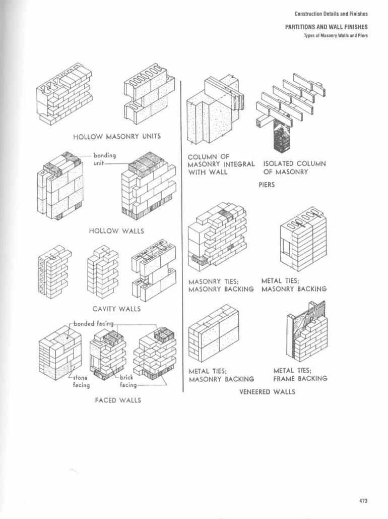
Construction Details and Finishes
PARTITIONS AND WALL FINISHEStypes of Masonry Walls and Piers
HOLLOW MASONRY UNITS
HOLLOW WALLS
CAVITY WALLS
METAL TIES ;MASONRY BACKING
MASONRY TIES ;MASONRY BACKING
ISOLATED COLUMNOF MASONRY
PIERS
COLUMN OFMASONRY INTEGRALWITH WALL
METAL TIES ;FRAME BACKING
METAL TIES ;MASONRY BACKING
VENEERED WALLSFACED WALLS

Construction Details and Finishes
PARTITIONS ANDWALL FINISHES
Fig . 1
Typical clay brick .
Fig . 2
Structural clay tile . Fig . 3
Structural facing tile .

Fig . 6
Structural clay tile : bearing (sections). A=structural clay tile, B=nominal wall thickness, C=finish .
Fig . 5
Hollow brick units : bearing or nonbearing (sections). A= brick, B=nominal wall thickness, C =finish .
Fig. 4
Solid brick : bearing or nonbearing (sections). A= brick, B =nominal wall thickness, C =finish.
Construction Details and Finishes
PARTITIONS ANDWALL FINISHES
Types of Masonry

Construction Details and Finishes
PARTITIONS AND WALL FINISHES ITypes of Masonry
Fig . 7
Faced or veneered construction : bearing (sections) . A=brick ; B=sheathing ; C=corrosion-resistant metal ties spaced 24in on centers, vertically and horizontally ; D=wood or steel studs ; E=plaster or gypsum wallboard ; F=masonry bond ; G=masonrybacking unit .
Fig . 8
Cavity type : bearing (sections) . A=clay brick, B=corrosion-resistant metal ties spaced to provide one tie to each 3 ftz ofwall surface, C=gypsum plaster, D=structural clay load-bearing tile, E=concrete masonry units of load-bearing grade,F=exterior face of wall .
Fig . 9
Hollow concrete masonry units (sections). (a) Bearing, (b) Non-bearing . A=concrete masonry units conforming to ASTM, Standard Specifica-tions for Hollow Load-Bearing Concrete Masonry Units; B=nominal wallthickness, C=nominal shell thickess, D=gypsum plaster.

Fig . 12
Structural clay facing tile : nonbearing (sections). A= clay tile, B= nominal wall thickness, C=plaster, D=glazed or smooth-surfaced side of tile .
Fig . 11
Gypsum tile or block: nonbearing (sections). A=gypsum block, B=nominal wall thickness, C=finish .
Fig . 10
Structural clay tile : nonbearing (sections) . A=structural clay tile, B=nominal wall thickness, C=finish, 0=fill .
Construction Details and Finishes
PARTITIONS ANDWALL FINISHES

Construction Details and Finishes
PARTITIONS AND WALL FINISHESBrick Types and Bonds

Fig . 14
Stone ashlar and rubble masonry.
Fig . 13
Designs of standard-size hollow concrete-masonry units .
Construction Details and Finishes
PARTITIONS AND WALL FINISHESMasonry Walls
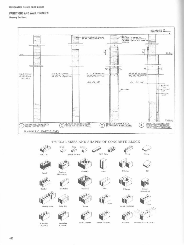
Construction Details and Finishes
PARTITIONS AND WALL FINISHESMasonry Partitions

Construction Details and Finishes
PARTITIONS ANDWALL FINISHESMetal Stud and Gypsum Board

Construction Details and Finishes
PARTITIONS AND WALL FINISHESMetal Stud and Gypsum Board
Metal stud and gypsum board : braced to slab Metal stud and gypsum board partition : floor to slab
Metal channels and gypsum board : wall furring Metal stud and gypsum board partition : floor to slab

Metal channels and gypsum board : wall furring
Metal stud and gypsum board : underside of ceiling
Construction Details and Finishes
PARTITIONS AND WALL FINISHESMetal Stud and Gypsum Board

Construction Details and Finishes
PARTITIONS AND WALL FINISHESMetal Stud and Gypsum Board
Metal stud and gypsum board : movableMetal stud and gypsum board : shaftwall

Construction Details and Finishes
PARTITIONS AND WALL FINISHESMetal Stud and Gypsum Board

PARTITION TYPES AND DIMENSIONING SYSTEM
Construction Details and Finishes
PARTITIONS AND WALL FINISHESMetal Stud and Gypsum Board
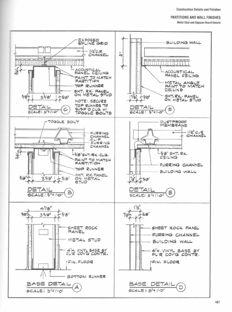
Construction Details and Finishes
'ARTITIONS AND WALL FINISHESMetal Stud and Gypsum Board Detalls
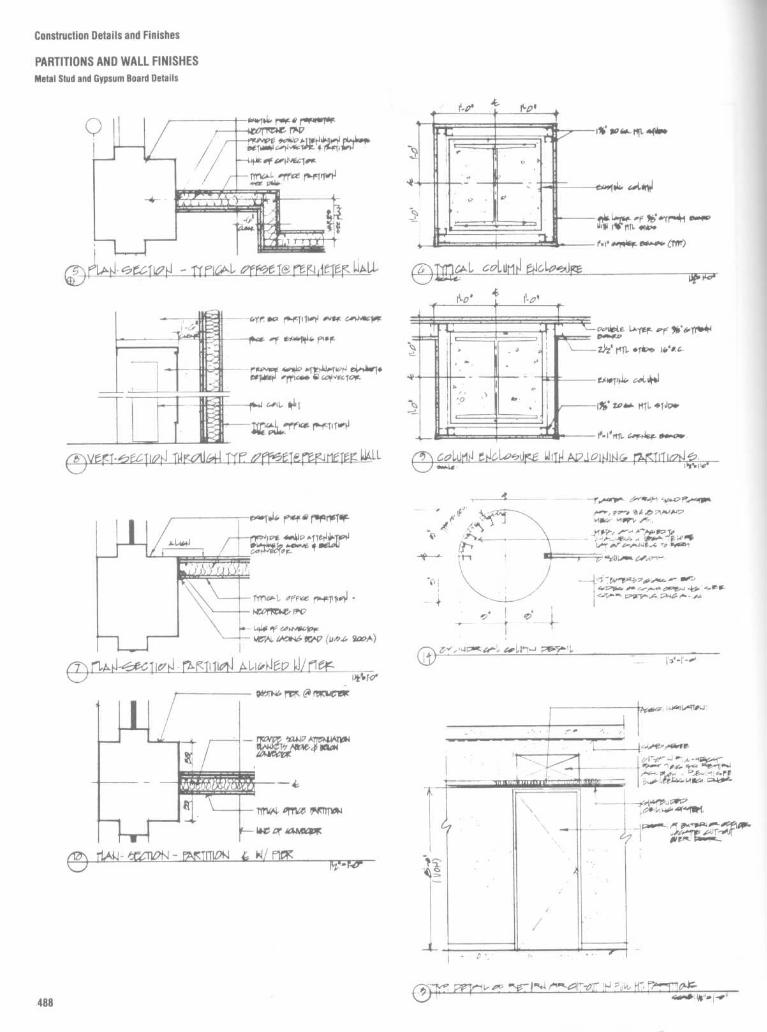
Construction Details and Finishes
PARTITIONS AND WALL FINISHESMetal Stud and Gypsum Board Details

Construction Details and Finishes
PARTITIONS AND WALL FINISHESMetal Stud and Gypsum Board Corner and End Conditions

Construction Details and Finishes
PARTITIONS AND WALL FINISHESMetal Stud and Gypsum Board : Partition Conditions
Metal stud and gypsum board : partition to mullion detail
Metal stud and gypsum board : partition to column detail
Metal stud and gypsum board : partition to mullion detail

Construction
Details and Finishes
PARTITIONS
AND WALL FINISHES
Metal
Stud and Gypsum Board
:
Column Enclosures and Fireproofing

Construction Details and Finishes
PARTITIONS ANDWALL FINISHES

Construction Details and Finishes
PARTITIONS AND WALL FINISHESMiscellaneous Metal Stud and Gypsum Board Details
t 9
._~~. . i
~i 1!
1!
r
1IO~I1Cfi~~iS~ il~d'at.~Of.1II(
-h ;
77
w4g ,64r. PIP
..
-"\ DETAIL FOR FIRE R&JED PART'bL
/-2\ S15CTK)Pi 04 UETAL.LjgL.UjQUjS0L
0 . , .r..
~J.~...~.
ow .
i
..
E.
A' 4"
"
FURRING
\ SECTION1AT SUPPLY AIR DUCT~a:CLart 1r.
O C~i
16 ga
0 4
. . CAMCAOLAK
O�©
L".
rJ
r
1 r
` .
2" 7
WW I=
Y
"AV 117"K44
w (20~)
l ..W .". . ""
".~i ~

PARTITIONS AND WALL FINISHESSound Insulation and Transmission
i ne resistance of a ounaing element, sucnas a wall, to the passage of airborne sound israted by its sound transmission class (STC).Thus, the higher the number, the better thesound barrier The approximate effective-ness of walls with varying STC numbers isshown in the following tabulation :STC No .
Effectiveness25
Normal speech can be understoodquite easily
35 Loud speech audible but notintelligible
45
Must strain to hear loud speech48
Some loud speech barelyaudible50
Loud speech not audibleSound travels readily through the air and
also through some materials . When airbornesound strikes a conventional wall, the studsact as sound conductors unless they areseparated in some way from the coveringmaterial .
Wall ConstructionAs the preceding STC tabulation shows, awall providing sufficient resistance to air-borne sound transfer likely has an STC ratingof 45 or greater. Thus, in construction of sucha wall between the rooms of a house, its costas related to the STC rating should be consid-ered . As shown in Fig . 5, details A, withgypsum wallboard, and B, with plasteredwall, are those commonly used for partitionwalls . However, the hypothetical rating of 45cannot be obtained in this construction .Good STC ratings can be obtained in a
wood-frame wall by using the combination ofmaterials shown in Fig . 5D and E. One-half-inch sound-deadening board nailed to thestuds, followed by a lamination of 1/2-in gyp-sum wallboard, will provide an STC value of46 at a relatively low cost . A slightly betterrating can be obtained by using V8-in gypsumwallboard rather than Y2-in . A very satisfac-tory STC rating of 52 can be obtained by usingresilient clips to fasten gypsum backerboards to the studs, followed by adhesive-laminated '/2-in fiberboard (Fig . 5E). Thismethod further isolates the wall coveringfrom the framing .A similar isolation system consists of re-
silient channels nailed horizontally to 2- by4-in studs spaced 16 in on center. Channelsare spaced 24 in apart vertically and 5/8-ingypsum wallboard is screwed to the chan-nels . An STC rating of 47 is thus obtained at amoderately low cost .Thus use of a double wall, which may
consist of a 2 by 6 or wider plate andstaggered 2- by 4-in studs, is sometimesdesirable . One-half-inch gypsum wallboardon each side of this wall (Fig . 6A) results in anSTC value of 45 . However, two layers of5/fl-in gypsum wallboard add little, if any,additional sound-transfer resistance (Fig . 6B).When 1 1/2-in blanket insulation is added tothis construction (Fig . 6C), the STC ratingincreases to 49 . This insulation may beinstalled as shown or placed between studson one wall . A single wall with 3'/2 in ofinsulation will show a marked improvementover an open stud space and is low in cost .The use of '/2-in sound-deadening board
and a lamination of gypsum wallboard in thedouble wall will result in an STC rating of 50(Fig . 6D). The addition of blanket insulation tothis combination will likely provide an even
494
higher value, perhaps 53 or 54 .
Fig . 6
Sound insulation of double walls .

Construction Details and Finishes
PARTITIONS AND WALL FINISHES
Acoustical and Fire-Rated Metal Stud and Gypsum Board

Construction Details and Finishes
PARTITIONS ANDWALL FINISHESAcoustical and Fire-Rated Metal Stud and Gypsum Board
a y.UantfUlW
Ioul:llalo
la~.rra: .r.l ~"~ Ô mtusi.~n
w. .w
y
e .
0100%, ,
we
[51
ILL PA Tl . . . ._ . ~PARTITION.~, i=_, _PA
RA AREA-SAMEAS f~] BUT
WITH
SAME AS FM BUT WMI
SOUND ATTENUATION
1TUSE TO ALIGN WITH PARTITION
r
,. _,.
i~n.ranenuucal
.~~OO~T
.v
NON-FIRE RATED ARIE-A
IM,
11
\_
1'. ., .
r
.
i
'rr
_
r
r
1;
IAL
.
,"
_.:
~~
:,~.
. 11 .
~ :
1
! . ,'FUR
OUT
t
IIA R'D .~.' 1Z'sls~l illl' ""LWy~"1 "MJ W1O .~
.
,O, .LI
.;SL.-+1.'.
SAME AS F71 11 .
E S fl
496

Construction
Details and Finishes
PARTITIONS
AND WALL FINISHES
Acoustical
Wood Veneer Plywood Wall Paneling

Construction Details and Finishes
PARTITIONS ANDWALL FINISHES
wood frame partition systems for sound control
Design No . 5-1 Hr . combustible (bearing wall) Underwriters' Lab, Inc . (10)rFace laminated vertically with three 6-inch wide strips of constructionadhesive and nailed with about half the usual number of nails .

Construction Details and Finishes
PARTITIONS ANDWALL FINISHES

Construction Details and Finishes
PARTITIONS AND WALL FINISHES
Wood Veneer Plywood Wall Paneling

Construction Details and Finishes
PARTITIONS ANDWALL FINISHES
Wood Veneer Plywood Wall Paneling

Construction Details and Finishes .
PARTITIONS AND WALL FINISHESWood Wall Paneling Details and Conditions
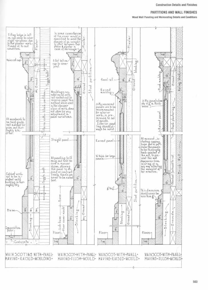
Construction Details and Finishes
PARTITIONS AND WALL FINISHESWood Wall Paneling and Wainscoting Details and Conditions

Construction Details and Finishes
PARTITIONS AND WALL FINISHESWall Paneling Elevation

Construction Details and Finishes
PARTITIONS AND WALL FINISHESCeramic Tile Wall Finishes
Wood Studs or Furring
Metal Studs
Glass Mesh Mortar UnitWood or Metal StudsGvosum Board

Construction Details and Finishes
PARTITIONS AND WALL FINISHESCeramic Tile Wall Finishes
MasonryCement Mortar
Cement Mortar One Coat Method
Masonry or Concrete
Organic Adhesive
Solid Backing
Recommended usesover masonry, plaster, or other solid
backing that provides firm anchorage formetal lath0 ideal for remodeling or on surfaces that
present bonding problems
Recommended usesover masonry, plaster, or other solid
backing that provides firm anchorage formetallath0 ideal for remodeling or on surfaces that
present bonding problems0 ideal for remodeling where space limita-
tions exist0 preferred method of applying tile over
gypsum plaster or gypsum board in showersand tub enclosures
Recommended useinteriors over gypsum board, plaster,
dimensionally stable masonry, or othersmooth surfaces

Fig . 15
Standard trim shapes and designations (6 by 41/4 in wall tile set in conventional mortar bed).
Construction Details and Finishes
PARTITIONS AND WALL FINISHESCeramic Tile Wall Finishes
Fig . 16
Standard trim shapes and sizes .

Fig .17
Marble treatment for walls and wainscots .
Construction Details and Finishes
PARTITIONS AND WALL FINISHESMarble Veneer Wall Finishes

Fig . 18
Anchorage details .
Construction Details and Finishes
PARTITIONS ANDWALL FINISHESMarble Veneer Wall and Ceiling Finishes

Construction Details and Finishes
PARTITIONS ANDWALL FINISHESMarble and Travertine Veneer Wall Finishes

Fig . 20
Slate panels applied to concrete wall .
Fig . 19
Slate panel veneer.
Construction Details and Finishes
PARTITIONS AND WALL FINISHESSlate Panel Veneer

Construction Details and Finishes
PARTITIONS AND WALL FINISHESReception and Pass-Through Windows
JAMS Pe7,41 L er 1 Nï~2S~GI~ol~
V~1ZT1~L S-~~TDI~(. i~izU LoBBy cON'r2ot~w~Mow

Construction Details and Finishes
PARTITIONS AND WALL FINISHESBi-Fold Door Details

Construction Details and Finishes
PARTITIONS AND WALL FINISHESColumn Fireproofing Details
GYPSUM LATH a PLASTER FIREP~OOFINy METAL LATH 4 PLASTER FIILEP200FING
MA50NRY FIREPROOFING

Construction Details and Finishes
PARTITIONS AND WALL FINISHESColumn Fireproofing Details
VEiZMICULITM OSZ. GYPSUM PEIZLITk FIV.EPrc0OFjWG

Construction Details and Finishes
FLOORS AND FLOOR FINISHES
The designer must be familiar with the great variety of floor types, finishes,
and patterns in order to specify and detail architectural flooring properly. While
some examples of "soft finishes" such as carpeting and resilient flooring are
shown, this section explores in depth the installation and detailing of "hard" or
architectural finishes .It is important for the designer to research the various characteristics of the
floor finish being specified. While aesthetics and color are obviously important
considerations, the designer must also analyze other factors . Among these
factors are wear resistance and durability, soil resistance, maintenance,
resiliency, flammability, costs of installation, and life cycle cost . Once these
factors have been analyzed, the final specification and detailing of the
architectural finish must be developed.Examples of standard patterns are provided, but the designer must become
familiar with the infinite number of pattern possibilities . The inherent
limitations of materials control their sizes and thicknesses. The patterns of
certain materials are dictated by both the thickness of the material and the
weight or "dead load" of the material superimposed upon the structure . For
example, a large pattern of marble or granite will necessitate a slab of material
that will weigh much more per square foot than that of a smaller pattern. This
greater weight might have structural consequences, as well as make floor
transitions more significant .Transitions between flooring materials, particularly under doors or at
entrances, and transitions between flooring and walls are some of the key
material interfaces that have to be detailed . Again, this section provides such
information using both traditional and contemporary approaches .
Finally, a portion of this section is devoted to the detailing of raised
computer room floors . While not traditionally a floor finish, raised computer
room floors seem appropriate for this section . While generic architectural
details are provided, the designer should always develop final details in
conjunction with the manufacturer(s) being specified .

DRAWING AND DESCRIPTIONSOIL RESISTANCE,
WEAR RESISTANCE
CLEANING AND
RESILIENCY
REMARKSMAINTENANCE
1,é inch hardened cementfinish on concrete slab
bâ inch terrazzo finish,with aié inch cementunderbed on a concreteslab
Ceramic mosaic tile .14 inch setting bed onconcrete slab
'Is inch asphalt tilefinish installed in masticon concrete slab
1/e inch linoleum finishinstalled in mastic onconcrete slab
1/e inch cork tile floorinstalled in mastic onconcrete slab
1/e inch rubber tilefinish installed in masticon concrete slab
1/s inch vinyl tile finishinstalled in mastic onconcrete slab
25/32 inch maple stripflooring set in 1/e inchhot asphalt mastic onconcrete slab
25/32 inch maple finish ;1 by 4 inch cypress sub-floor laid diagonally;2 by 6 inch cypress sleep-ers, 12 inches apart, setin two 1/e inch layers ofhot asphalt mastic
Poor ; frequentcleaning needed ;
Good
must be refinished
Very hardevery ten years
Very good ; needscleaning once a week
Very good
with detergent and
Very hardwater
very good
Very good
Very hard
Poor, usuallyneeds re-
Fair ; must beplacing every
cleaned and waxed
Fairten years
once a week.
Fair ; must beGood
cleaned and waxed
Faironce a week
Fair ; needs frequentGood
cleaning and waxing
Very good
Fair ; needs cleaningGood
and waxing once
Very gooda week
Fair ; needs aGood
weekly cleaning and
Very goodwaxing
Good ; requiresmonthly cleaning
Very good
with steelwool and
Faira wax finish
Good : requires amonthly cleaningwith steelwool and
Very good
awax finish ; sand
Excellentand re-finish every2 years
Construction Details and Finishes
FLOORS AND FLOOR FINISHEStypical Characteristics of Floor Finishes
COST COMPARISON
Cement base costs little,is too hard a floor to becomfortable; Infrequentlyused in classroom"., some-times used in corridors,;Cops dnd inexpensivetoilet rooms
Terrazzo base is easy toclean and sanitary, butnot resilient and some .times noisy; seldom usedin classrooms, often usedin corridors, vestibules,toilets and shower rooms
Used in toilet rooms,showers, food serviceareas, but seldom used inclassrooms
Low first cost ; finishrequires carefulmaintenance
Serviceable ; a sanitaryfloor for classrooms,corridors, assembly andadministration rooms
Used primarily in librariesand kindergartens; flooris subject to indentationsby chair legs; acousticallygood
Subject to slight inden-tation by chair legs
Subject to indentation
Steel angles necessary tocover expansion joint ;used in gymnasiums andplayrooms; not suitablefor damp areas or climates
A deluxe gymnasium floor
installation cost
maintenance andinsurance costf)r 20 years

Construction Details and Finishes
FLOORS AND FLOOR FINISHESFloor Construction Details

Construction Details and Finishes
FLOORS AND FLOOR FINISHESFloor Tile Patterns

TYPICAL MARBLE FLOORING DESIGNS
',e"='`o"
Construction Details and Finishes
FLOORS AND FLOOR FINISHESMarble Floor Patterns and Details
METHODS OF INSTALLATION
HALF SIZE
Fig . 1
Marble flooring details .
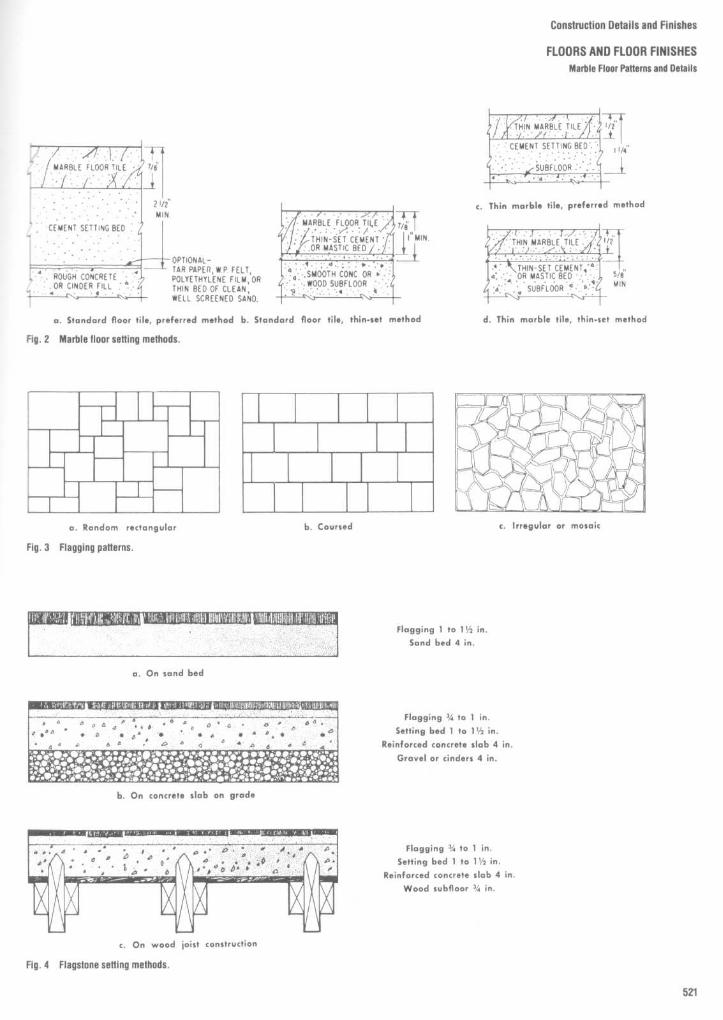
Construction Details and Finishes
FLOORS AND FLOOR FINISHES
Marble Floor Patterns and Details
Fig . 3
Flagging patterns.
Fig . 4
Flagstone setting methods .
Flagging 1 to 1 1/2 in .
Sand bed 4 in .
Flagging 2/, to 1 in .
Setting bed 1 to 1 1/2 in .
Reinforced concrete slab 4 in .
Gravel or cinders 4 in .
Flagging 2/ to 1 in .
Setting bed 1 to 1 1/2 in .
Reinforced concrete slab 4 in .
Wood subnoor 2/ in .

Construction Details and Finishes
FLOORS AND FLOOR FINISHESSaddles/Floor Transitions
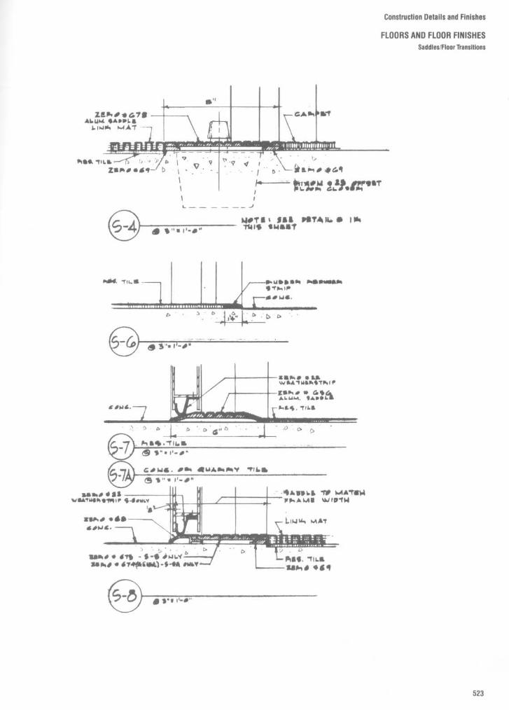
Construction Details and Finishes
FLOORS AND FLOOR FINISHES
Saddles/Floor Transitions

Construction Details and Finishes
FLOORS AND FLOOR FINISHESSaddles/Floor Transitions

Construction Details and Finishes
FLOORS AND FLOOR FINISHES
Door Saddles

Construction Details and Finishes
FLOORS AND FLOOR FINISHES
Door Saddles

i;onstrucl ,on Celai+s and Finishes
FLOORS AND FLOOR FINISHES
Saddles/Floor Transitions

Construction Details and Finishes
FLOORS AND FLOOR FINISHESSaddles/Floor Transitions

Construction Details and Finishes
FLOORS AND FLOOR FINISHESFloor Finish Transition Details

Construction Details and Finishes
FLOORS AND FLOOR FINISHES
Floor Finish Transition Details

Construction Details and Finishes
FLOORS AND FLOOR FINISHESEdgings ; Tile/Carpet Joiners ; Reducer Strips
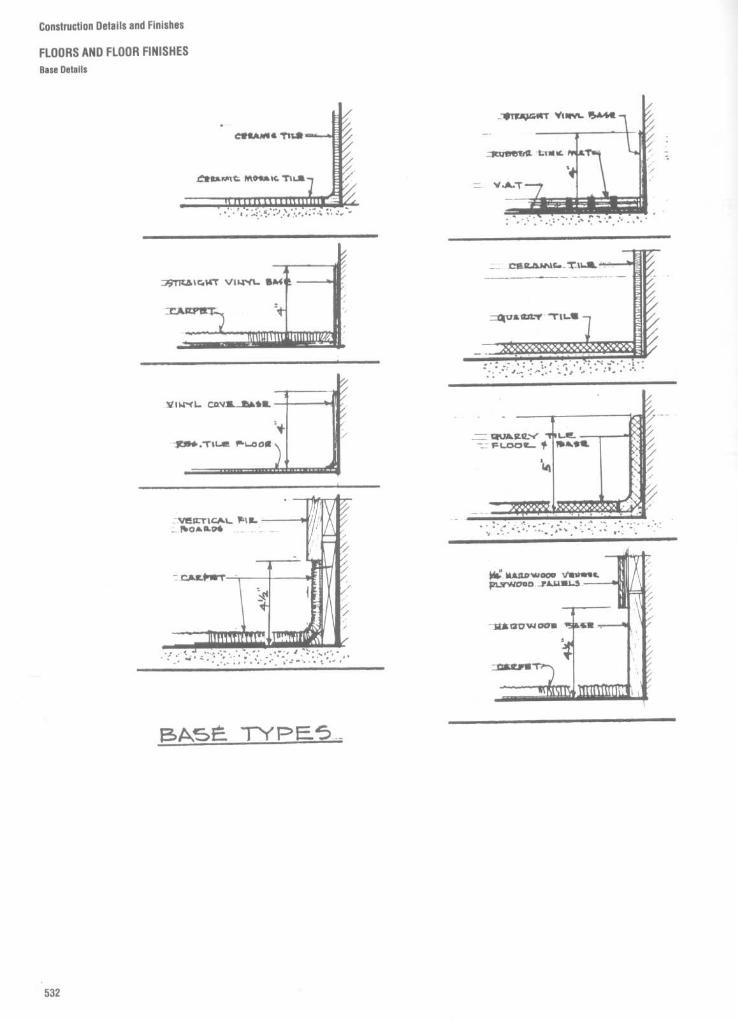
Construction Details and Finishes
FLOORS AND FLOOR FINISHES
Base Details

Construction Details and Finishes
FLOORS AND FLOOR FINISHES
Baseboards

Construction Details and Finishes
FLOORS AND FLOOR FINISHESStone Floor Patterns and Details

Construction Details and Finishes
FLOORS AND FLOOR FINISHES
Terrazzo Floor Construction Details

Construction Details and Finishes
FLOORS AND FLOOR FINISHESTerrazzo Floor Construction Oetalls

Construction Details and Finishes
FLOORS AND FLOOR FINISHESTerrazzo Floor Construction Details

Construction Details and Finishes
FLOORS AND FLOOR FINISHESTerrazzo Base Details

Construction Details and Finishes
FLOORS AND FLOOR FINISHESTerrazzo Stair Tread Details
PRE-CAST TERRAZZOSTAIRS
NOTE : Abrasive inserts should
POURED TERRAZZO STAIRS
VERTICAL RUSTIC TERRAZZO
TEXTURED MOSAICEpoxy, _Polyester or Polyacrylate

Construction Details and Finishes
FLOORS AND FLOOR FINISHESCeramic Tile, Terrazzo, and Brick

Construction Details and Finishes
FLOORS AND FLOOR FINISHESMarble, Resilient Tile, Slate, Wood, and Quarry Tile

Construction Details and Finishes
FLOORS AND FLOOR FINISHES
Wood Floor Construction Details

Construction Details and Finishes
FLOORS AND FLOOR FINISHESWood Strip Floor Construction Details
Perhaps the most widely used pattern is a25/3z- by 21/4-in strip flooring . These strips arelaid lengthwise in a room and normally atright angles to the floorjoists . Some type ofasubfloor of diagonal boards or plywood isnormally used under the finish floor. Stripflooring of this type is tongued-and-groovedand end-matched (Fig . 6). Strips are randomlength and mayvary from 2 to 16 ft or more .End-matched strip flooring in z5/32-in thick-ness is generally hollow backed (Fig . 6A). Theface is slightly wider than the bottom so thattight joints result when flooring is laid . Thetongue fits tightly into the groove to preventmovement and floor "squeaks ." All of thesedetails are designed to provide beautifulfinished floors that require a minimum ofmaintenance .Another matched pattern may be obtained
in 3/s- by 2-in size (Fig . 68). This is commonlyused for remodeling work orwhen subfloorisedge-blocked or thickenough to provide verylittle deflection under loads .Square-edged strip flooring (Fig . 6C) might
also be used occasionally. It is usually 3/s by 2inches in size and is laid up over a substantialsubfloor Facenailing is required for this type .
Fig. 6
Types of strip flooring : A, side- and end-matched - 25/32-in ; B, thin flooring strips - matched; C,!bi flooring strips - square-edged .
Fig . 7
Application of strip flooring : A, general application ; B, starting strip .

Construction Details and Finishes
FLOORS AND FLOOR FINISHES
Wood Parquet Floor Patterns
PRODUCT DESCRIPTIONAND PATTERN
STANDARD PatternUnfinished-paper-laced
STANDARD PatternUnfinished-Web Back orMesh-Back
STANDARD PatternUnfinished -WebBackFor Industrial Usel
STANDARD PatternUnfinished WebBack)For Industrial Use)
STANDARD PatternFactory-Finished andUnfinished(Available in various colors)
STANDARD PatternFactory-FinishedFoam-Back Tile
ANTIQUE TEXTURED(Factory-Finished andUnfinished)- KerfsawnVarious colors available
ANTIQUE TEXTURED(Factory- Finished andUnfinished) -Wire brushedVarious colors available
MONTICELLO PatternUnfinished-Paper-Faced-
Pre-Finished . Mesh-Back
HADDON HALL PatternUnfinished-Paper-Faced-
Pre-Finished . Mesh-Back
HERRINGBONE PatternUnfinished-Paper-Faced
SAXONY PatternUnfinished-Paper-Faced
CANTERBURY PatternUnfinished-Paper-FacedPre-Finished. Mesh-Back
RHOMBS PatternUnfinished-Paper-Faced
BASKET WEAVE PatternUnfinished-Paper-Faced
ITALIAN S DOMINO PatternUnfinished-Paper-Faced
'PANEL SIZE
5/16' x 19' x 19"16 equal alternating squares
5/16" x 12" x 12"4 equal alternating squares
5/16'x19 x19'16 equal alternating squares
5/16"x 11"x 11"4 equal alternating squares
5/16 - x 19 - x 19"16 equal alternating squares
9/16"'19
x 19"16 equal alternating squares
I1/16' x l I
x 11'4 equal alternating squares
Y" x 12-11/16" x 12-11/16'4 equal alternating squares
5/16'x 6-11/32 x 6-11/32"5/16" x 2" x 12" (slats)5/16'x6" x6"5/16" x6% " x6%"5116x6Yé x6Yiindividual unit
5/16 x 6Yv x 6Yi'Individual units, .%" loam, 2 lb . density
5/16 x6 x6individual squares5/16 x e% x 63i'individual squares5/16" x 6Yd' x 6Yr"individual squares5/16" x 11
x 11'4 equal alternating squares
5/16 x 635" x 63(1"5/I6"x6Yi x6Yvindividual squares
5/16x6 - x6individual squares usedwith 5/16 - x Y x 8" pickets5/16 x 13Y x 13 i/,4 equal alternating squares5/16 - x 13 ;5 - x 13%(Factory Finished)
5/16x14Y, x 14Y,5/16 x 13Y' x 13Y4 equal squares5/16" x 13%
x 135s-(Factory Finished)
5/16x2'x12individual slats5/16 x 145j
.x 18%'
(Approximate overall)2-' .V., shape courses wideand 11 slats long
5/16 x 19 x 19'4 equal squares on diagonaland 8 equal hall squares
5/16 " x 13Y - x 13Y4 equal alternating squareswith diagonal center slats5/16 x 1355 x 1354
Hexagonal Shape5/16" x 1555" x 15~j
12 equal Rhomboids
5/16 x 15-1/5 x 194 runs of 3 slats and5 slats alternating
5/H3 ' x 19'
x 19400 equal size piecesbutt-jointed
GRADE
Select 6 Better
Rustic
Select 8 BetterRusticSelect 8 Better(Par 6 Better)Rustic
Select d Better(Par a Better)
Select Rustic dBetter Rustic
Select & Better(Par 6 Better)
Select 8 Better(Rustic d Better)
Select 6 BetterNatural 8 BetterFiresideRusticCabin 8 BetterCabin
Natural & BetterCabin 8 BetterCabin
SelectNatural 6 BetterSelect E Better(Par d Belle,)RusticFireside
Natural E BetterCabin
Select 8 Better
(Par 8 Belief I
RusticNatural d Better
Select b Better(Par d Better)RusticNatural 8 Better
Select d Better(Par b Seller)
Select 8 Better(Par d Belle,)
Select d Seller(Par 8 Better)Natural 8 Better
Select a Better(Par d Better)
Rustic
Select d Better(Par d Better)
Select b Beller(Par 8 Better)
'SPECIES
Cherry, Maple . Red Oak,White Oak, Cedar, Pecan,Walnut, Rhodesian Teak,Angelioue (Guiana Teak)
Red Oak, While Oak . PecanPecan
Red and While Oak
Maple, Red OakWhite OakPecan
Red Oak. MapleWhile Oak
Oak . Walnut
Pecan, MapleWhite Oak . Ash
Oak .PecanMaple
Red Oak 6 White OakRed Oak d While Oak
Oak
Angelique (Guiana Teak)
Red Oak . While Oak
Black WalnutAsh Maple
Angellque (Guiana Teak)Red Oak, White OakBlack Walnut
Angelique (Guiana Teak)Red Oak, White OakBlack Walnut
Angellque (Guiana Teak)Red Oak. While Oak
Angelique (Guiana Teak)Red Oak . While OakBlack Walnut
Red Oak 8 While OakAngelique (Guiana Teak)Black Walnut
Angelique (Guiana Teak)Red Oak . While OakBlack Walnut
Black WalnutAngelique (Guiana Teak)Maple . Red OakWhile Oak

Construction Details and Finishes
FLOORS AND FLOOR FINISHES
Wood Floor Patterns
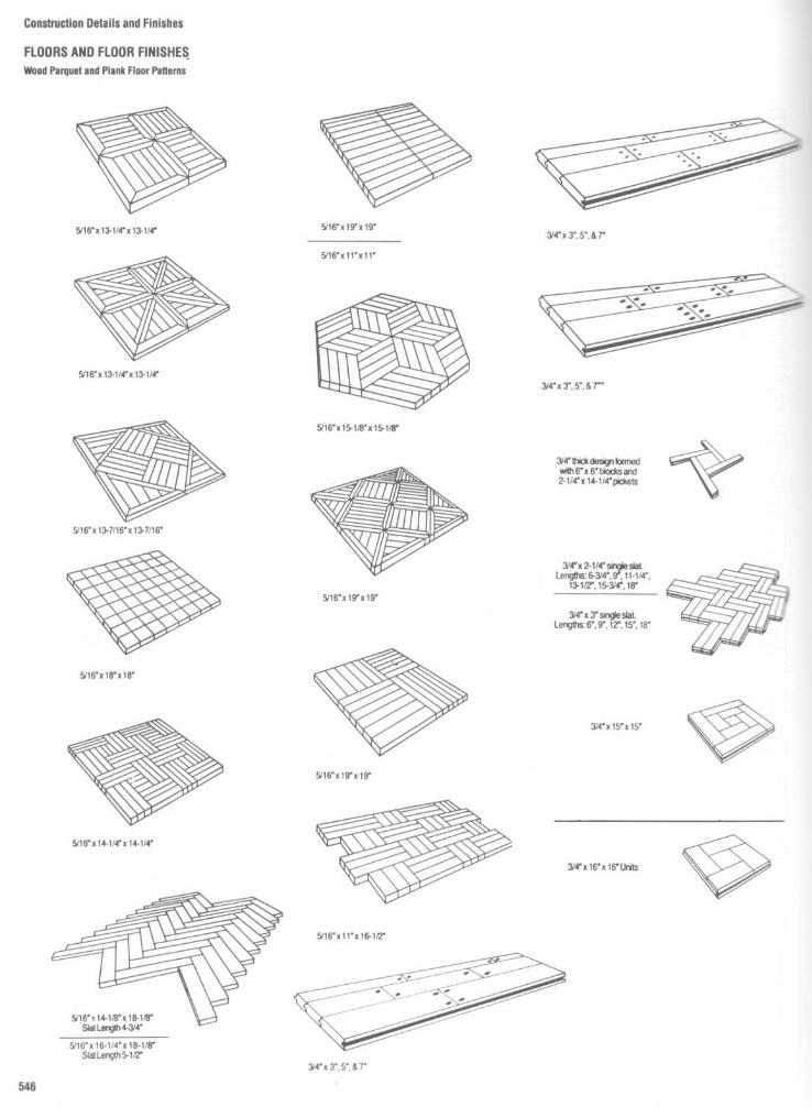
Construction Details and Finishes
FLOORS AND FLOOR FINISHESWood Parquet and Plank Floor Patterns +

Construction Details and Finishes
FLOORS AND FLOOR FINISHES
Wood on Concrete Slab Floor Construction Details

Construction Details and Finishes
FLOORS AND FLOOR FINISHES
Floor Construction Sound Insulation
Sound insulation between an upper floorand the ceiling of a lower floor not onlyinvolves resistance of airborne sounds butalso that of impact noises . Thus, impactnoise control must be considered as well asthe STC value . Impact noise is caused by anobject striking or sliding along a wall or floorsurface, such as by dropped objects,footsteps, or moving furniture . It may also becaused by the vibration of a dishwasher,bathtub, food-disposal apparatus, or otherequipment. In all instances, the floor is setinto vibration by the impact or contact andsound is radiated from both sides of the floor.A method of measuring impact noise has
been developed and is commonly expressedas the impact noise ratings (INR). The greaterthe positive value of the INR, the more
resistant is the floor to impact noise transfer.For example, an INR of -2 is better thanone of -17, and one of +5 INR is a furtherimprovement in resistance to impact noisetransfer.
Figure 8 shows STC and approximateINR(db) values for several types of floorconstructions. Figure 8A, perhaps a mini-mum floor assembly with tongued-and-grooved floor and 3/8-in gypsum board ceiling,has an STC value of 30 and an approximateINR value of -18. This is improved some-what by the construction shown in Fig . 8B,and still further by the combination of mate-rials in Fig . 8C .The value of isolating the ceiling joists from
a gypsum lath and plaster ceiling by means ofspring clips is illustrated in Fig. 9A . An STC
value of 52 and an approximate INR value of-2 result .Foam-rubber padding and carpeting ir^-
prove both the STC and the INR values . TheSTC value increases from 31 to 45 and theapproximate INR from -17 to +5 (Fig . 9Eand C) . This can likely be further improved b,using an isolated ceiling finish with sprir=clips. The use of sound-deadening board arza lamination of gypsum board for the ceilircwould also improve resistance to sounctransferAn economical construction similar to (but
an improvement over) Fig. 9C, with a STCvalue of 48 and an approximate INR of +18.consists of the following : (a) a pad and carpetover 5/8-in tongued-and-grooved plywood un-derlayment, (b) 3-in fiberglass insulating

Construction Details and Finishes
FLOORS AND FLOOR FINISHESFloor Construction Sound Insulation
wars between joists, (c) resilient channels=aced 24 in apart, across the bottom of thetoss, and (d) 5/s-in gypsum board screwed tore oottom of the channels and finished with,aoed joints .
'~,e use of separate floor joists with stag-pered ceiling joists below provides reason-aDe values but adds a good deal to construc-icr costs . Separate joists with insulationaetween and a soundboard between sub-Noc . and finish provide an STC rating of 53fi,ü an approximate INR value of -3 .
fund absorption Design of the "quiet"~i-se can incorporate another system of=_,_-d insulation, namely, sound absorption .'N_Lnd-absorbing materials can minimize the
amount of noise by stopping the reelection ofsound back into a room . Sound-absorbingmaterials do not necessarily have resistanceto airborne sounds . Perhaps the most com-monly used sound-absorbing materials isacoustic tile . Wood fiber or similar materialsare used in the manufacture of the tile, whichis usually processed to provide some fireresistance and designed with numerous tinysound traps on the tile surfaces . These mayconsist of tiny drilled or punched holes,fissured surfaces, or a combination of both .
Acoustic tile is most often used in theceiling and areas where it is not subjected toexcessive mechanical damage, such asabove a wall wainscoating . It is normallymanufactured in sizes from 12 by 12 to 12 by
48 in . Thicknesses vary from 1/2 to 3/4 in, andthe tile is usually factory finished ready forapplication . Paint or other finishes which fillor cover the tiny holes or fissures for trappingsound will greatly reduce its efficiency.Acoustic tile may be applied by a number
of methods - to existing ceilings or anysmooth surface with a mastic adhesive de-signed specifically for this purpose, or tofurring strips nailed to the underside of theceiling joists . Nailing or stapling tile is thenormal application method in this system . Itis also used with a mechanical suspensionsystem involving small "H ;" "Z ;" or "T"members . Manufacturers' recommenda-tions should be followed in application andfinishing .

Construction Details and Finishes
FLOORS AND FLOOR FINISHESFloor construction Sound Insulation
conventional wood floor joist systems for sound control
The improved resistance to airborne sound transmission gained by isolating the ceiling with resilient channels and adding absorptive materais evident by comparing floors 2 to 5 with No . 1 . A 10-point increase in STC reduces the loudness of transmitted noise by one-half . Improvesresistance to impact noise transmission is gained by adding carpet and pad as is evident by comparing floor No . 3 with No . 2 or floor No .with 4 . An IIC of 51 is often recommended as an acceptable level of impact insulation .

Standard toe baseNo-toe base : Adds a decorative
mk .-ch to carpeted interiors .Butt toe base : Engineered to butt
arecisely to Yé' floor coverings.Long toe base :
For special applica-tbons. Features a longertoe extending 1"to=rer wide irregularities between floora'+d wall .
ALE 1
Cove Base Specifications
Type
Sizes available
-lard toe base
2112"
4"
6"- -- :)e base
2'h" 4" 6":oe base
4"
6"toe base
4"
_= - 7th : 48"
TABLE 2
Corner Specifications
Type
Length of return
Inside/outside
2'/4"Underlap outside
3" (with underlap)No-toe outside
2'/4"Long toe outside
2'/4"
Sizes available
2 112" 4" 6"4"
2112" 4"4"
Construction Details and Finishes
FLOORS AND FLOOR FINISHES
Resilient Base Details

Construction Details and Finishes
FLOORS AND FLOOR FINISHES
Ceramic Tile Patterns

Construction Details and Finishes
FLOORS AND FLOOR FINISHESCeramic Tile Patterns

Construction Details and Finishes
FLOORS AND FLOOR FINISHESCeramic Tile Patterns

Construction Details and Finishes
FLOORS AND FLOOR FINISHES
Ceramic Tile Patterns

Construction Details and Finishes
FLOORS AND FLOOR FINISHES
Ceramic Tile Patterns

Construction Details and Finishes
FLOORS AND FLOOR FINISHESCeramic Tile Patterns
:o :e to the complexity of mounting 1 " Hexagon border;attern corners which require a number of specialsrseets on smaller jobs, a premium charge is made . Toavoid this, it is suggested that on smaller jobs theaorder be formed using 1 " squares with a hexagon field .
If a Hexagon border is required, you must provide a plan ofthe area with dimensions because the Hexagonconfiguration precludes interchanging sheets . We willprovide specific sheets for those areas and setting plans .
Note that on three of these border patterns a full sheet is used for the corner . Some designs, however, will require ahalf sheet for the corner as shown in SB-1404. In this case a right and left corner will be on one sheet and the sheetis cut in half before placement .
Fig . 16
1" hex border patterns . All patterns master-set 12" x 24" sheets .

Construction Details and Finishes
FLOORS AND FLOOR FINISHES
Ceramic Tile Patterns

Construction Oetalls and Finishes
FLOORS AND FLOOR FINISHES
Basic Quarry Tile Patterns

Construction Details and Finishes
FLOORS AND FLOOR FINISHESBasic Quarry Tile Patterns

commended usesse over wood floors where resistance toi- traffic in better residential, normal com-- _-~ al, and light institutional use is desired
thin-set constructiona vhere water, chemical, and stain re--ce is desired0 'or tilework exposed to prolonged high
=,- peratures, use high temperature, chem-resistant epoxy mortar, and grout
Recommended usesover structurally sound plywood where
lightweight construction is a factoro where water resistance is desiredsis eliminates necessity of recessing sub-
floor to accommodate portland cement mor-tar bed
Construction Details and Finishes
FLOORS AND FLOOR FINISHES
Floor construction Details : Ceramic Tlle on Wood and Concrete Subfloors
Wood SubfloorEpoxy Mortar and Grout
Glass Mesh Mortar UnitsDry-Set Mortar orLatex-Portland Cement
Recommended usesis over a mortar bed
over glass mesh mortar unitsover clean, sound, dimensionally stable
concretess over metal lath attached directly to the
bottom of wood joists or trusses ; spacing notto exceed 16" on center

Construction Details and Finishes
FLOORS AND FLOOR FINISHESCeramic Tile on Concrete Slab Floor Construction Details
CONCRETE SUBFLOOR
Cement MortarCleavage Membrane
Cement Mortar,Bonded
Dry-Set Mortar orLatex-Portland Cement Mortar
(Recommended useI over structural floors subject to bending
and deflectionRequirements
reinforcing mesh mandatorymotor bed thickness to be uniform,
nominal 1 1/4" thick
Cement MortarEpoxy or Furan Grout
Recommended usesss on slab-on-grade construction where no
bending stresses occurss on properly cured structural slabs where
deflection does not exceed 1/360 of spanm on properly cured structural slabs of
limited area
Dry-Set Mortar,Epoxy or Furan Grout
Recommended uses" on plane, clean concrete" on slab-on-grade construction where no
bending stresses occur
Organic Adhesive orEpoxy Adhesive
Recommended usesin with tile set by Method F111 requiring
good stain resistance and resistance to ero-sion caused by occasional contact with mildchemicals such as found in commercial din-ing areas, photographic dark rooms, publictoilets, public foyers, etc.
ss for use with quarry tile and paver tile
WATERPROOF MEMBRANE
Cement Mortar Bed
Recommended usesin with tile set by Method F112 or Method
F113 requiring good stain resistance andresistance to erosion caused by occasionalcontact with mild chemicals such as found incommercial dining areas, photographic darkrooms, public toilets, public foyers, etc .
ss for use with quarry tile and paver tile
Thin-Set
Recommended usess for use over concrete floors in residen-
tial construction only ; for heavier serviceselect Method F113
Recommended useis wherever a waterproof interior floor is
required in conjunction with ceramic tileinstalled on a portland cement mortar bed
Recommended usein wherever a waterproof interior floor is
required in conjunction with ceramic tileinstalled in a thin-set method

Construction Details and Finishes
FLOORS AND FLOOR FINISHES
Ceramic Tile on Concrete Slab Floor Construction Details
+bmmended usesr setting and grouting ceramic mosa-
~r=
P~arry tile, and paver tile6 %here moderate chemical exposure and
jowFre cleaning methods are used, such as in=-r^ercial kitchens, dairies, breweries,min: processing plants, etc.a = :r tilework exposed to prolonged high
Ef-ceratures, use high-temperature, chem-~caiii-resistant epoxy mortar and grout
i
Recommended usesin where leveling of subfloor is required
for setting and grouting ceramic mosa-ics, quarry tile, and paver tile
where moderate chemical exposure andsevere cleaning methods are used, such as incommerical kitchens, dairies, breweries,food processing plants, etc.
is for tilework exposed to prolonged hightemperatures, use high-temperature chem-ical resistant epoxy mortar and grout
Recommended useM for setting 1 1/4" thick packing house tile in
areas of continuous or severe chemical ex-posure where special protection against leak-age or damage to concrete subfloor isrequired
=-r2.t4Mir- TI LE
F
Ur`1AJJ Git~Ut
rORTAR
r~ ccar

Construction Details and Finishes
FLOORS AND FLOOR FINISHESRaised Computer Room Floors

Construction Details and Finishes
FLOORS AND FLOOR FINISHESRaised Computer Room Floors

Construction Details and Finishes
DOORSHallow Metal Door Construction
The design, specification, and detailing ofa door can have serious consequencesfor functional considerations such as ac-cessibility and sound transmission . The dooris also one of the most important architec-tural elements with respect to design imageand aesthetics . A door can be a major part ofdesign expression : a monumental door to achurch or synagogue, the main entrance to aresidence, the doors to a corporate boardroom - all of these doors have symbolicimportance .Doors come in a variety of standard
heights, widths, and thicknesses, yet theymay also be custom designed, assume a
variety of shapes and forms, and be con-structed with a variety of materials . Thedesign, specification, and detailing of a dooris, in fact, a rather complex task .A door is typically set within a frame or
jamb, but may also be installed within a wallwithout a frame or jamb . The frame/jambinterface between door and wall partition isanother area requiring special attention bythe designer.The design of a door is never complete
without the specification of hardware .Hinges, locksets, closers, stops, and thresh-olds are but a few of the hardware elementsthat a designer must consider.
This section on doors provides the orsigner with extensive information on Boartypes, materials, door frames, and materat:and methods of door construction and r"stallation . Details show doors and frar-,ftinstalled in all types of walls and partitiorsincluding wood and metal stud, mason%concrete, and glass .Of special interest to the designer apt
examples of less standard door types suc- welevator doors, sliding pocket doors, a-cfabric-covered doors . The majority of ---details in this section are taken from :~-actual working drawings of successfully =~ecuted projects .
PANEL CONSTRUCTIONThere are two basic types of panel construction :
Steel stiffened : Face sheets supported by steel stiffeners, which are channels, Z-shaped sections, hat-shaped sections, or similarmembers, positioned vertically Sheets are attached to these members by spot welding .
Laminated core : Sandwich construction employing a core of impregnated kraft paper honeycomb, plastic foam, or structuralmineral blocking, to which the steel face sheets are laminated, using a structural adhesive .
REPRESENTATIVE STIFFENER SECTIONSOther sections used by some manufacturers
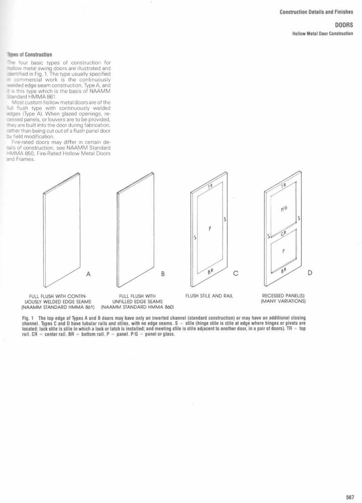
YM=of Construction-'r 'our basic types of construction forfialc~ metal swing doors are illustrated andeoer"!ified in Fig. 1 . The type usually specifiedr :ommercial work is the continuously+ceded edge seam construction, Type A, andc s this type which is the basis of NÀAMMStandard HMMA 861 .Most custom hollow metal doors areof the
to flush type with continuously weldededges (Type A) . When glazed openings, re-zessed panels, or louvers are to be provided,T'ey are built into the door during fabrication,-3rtter than being cut out of a flush panel door:N field modification .
Fire-rated doors may differ in certain de-~Is of construction ; see NAAMM Standard--MMA 850, Fire-Rated Hollow Metal Doorsand Frames .
Construction Details and Finishes
DOORS
Hallow Metal Door Construction
FULL FLUSH WITH CONTIN-
FULL FLUSH WITHUOUSLY WELDED EDGE SEAMS
UNFILLED EDGE SEAMS(NAAMM STANDARD HMMA 861)
(NAAMM STANDARD HMMA 860)
FLUSH STILE AND RAIL
RECESSED PANEL(S)(MANY VARIATIONS)
Fig. 1
Thetop edge of Types A and 8 doors may have only an inverted channel (standard construction) or may have an additional closingchannel . Types C and D have tubular rails and stiles, with no edge seams. S = stile (hinge stile is stile at edge where hinges or pivots arelocated ; lock stile is stile in which a lock or latch is installed ; and meeting stile is stile adjacent to another door, in a pair of doors). TR = toprail . CR = center rail . BR = bottom rail . P = panel. PIG = panel or glass.

Construction Details and Finishes
DOORSHollow Metal Door Types
OTHER DOOR SIZES : The sizes listed are those most commonlyused, but custom hollow metal doors are available in any width,height and thickness desired . It is not uncommon to supply them inwidths of 5'or more and/or heights of 10' or more . Standard doors,on the other hand, are generally available from inventory only in themost commonly used sizes .
LISTING DESIGNATION : Always preface the door listing with"SGL" or "PR," followed by the designation ofthe opening size . Forexample, a single flush door for a 4'0" x 8'0" frame opening islisted SGL 4080F, and a pair of flush doors for an 8'0" x 8'0"frameopening is listed as PR 8080F .
MOST COMMON SIBS FOR 1%-INCH THICK DOORS'
DIMENSIONS AND HINGE LOCATIONSHinge locations shown represent the industry standard,
but may be altered to suit requirements .
REPRESENTATIVE DOOR DESIGNS

Construction Details and Finishes
DOORSHollow Metal Door Hardware
TYPICAL HARDWARE PREPARATION
NOTE : CUTOUTS ANDIOR REINFORCEMENTS OF SIMILAR NATUREARE PROVIDED FOR ALL OTHER HARDWARE ITEMS SUCH AS FLUSHBOLTS, SURFACE-MOUNTED CLOSERS, FIRE EXIT HARDWARE, PULLS, ETC .

Construction Details and Finishes
DOORSHollow Metal Door Schedules
W12
CColx
D E
N
M 09E 0O~aif/1m Nm mt mL NE3E 8Ô
O .ip H
N mDm A
E .DO i0 =~
2 C D mé E$
âC H'H E
;;~"ciT~l
Omm ÉEa =D `~
ri8y LLCr'dôO
m UCN m NNN Y1 dU~ B
O3~ô
N_Rw. t2
L m E3 >. ,c C-Ae . t0mD `° vT.H f O~D .
É mys~_ mEEfgQeEC
ç ôLm~S
;N ~ O0L N m ::CGY ÛLâ
E gO
Ct0 d$Ei E m
â , 0OZ ~,
rd
mo
mm mEC E 0L UU
cm 03ô m
D~m E
cy O m Nm m
~ C~W m à
lL Oci m =,'
C
 N~=m
E U)
N
TN
O4i m~ ~DÔcC
~ c 0
N ND
- NmCO O1,
tCL U_ô
aE
a~>UOO
H _a OD ~ C
m .
00
> OmN
m N0D
a_ O
C m-_- m
ôL_
M . m;,D
L $c YDy Vi
U.3
W .L.p
6' m >m a
OCO
.mtôôro ôâJZJD C7ZO
cacà
mA
W UÔ
O mL_G
_U ..Om m° E =mE
22 NO.,m
A c Çm
Û O ?`m màâ
Z .5 Om
~~ â
h
$_
E m .~. ,~a
m ~ m miafAH QZmO
~7 <
N
m
II
Éy
$É~°D
UO w ?>
N 3 ~ t6E II m ya E
,~LC c amrC
g cD âm .mÉôD
~D N ,N OLEd Lm ` : U '_
o Em
.0 O p
W m E
_NU N!D 3 d OH _O " m .Um O ~ aO.~ L DH N
vi
ÂNC
NNm C, roNLNNw
kLm
;DotNyD
$ ô
`ô
m a~Om .. 3m Ô mL m âa
4 e l7acmO
- 'D C°' ô
cc mô
C O1düD ~0mâ` ô
~ É 3
W ÔNZ L
n
3!~Ôcmôw aiD- D N
m O U `a10o m U OO c a NDY NaU
ômm
dd
âECor
v
É\
Sv C
V
:y
+-
Çâ
la¬
tn
4ô vr
â
=3 - ao d - in r l~-
N
rQ
I I I I Q I I~
I I , l
I I I I I I I I I ~ , ~ I ~
W
N \ ~ MW
tY 'n nV
~_ nJ
nN
n n n n n n
9 :1= -JQ
:Es :2,x >=1 57_
~ >_
-~>~x x
>1x
~H -
I I I I I I I M
r, aZ5
I~ I1Iarl ,[
I I I I , I
un Mon
J _3 rrrrrr©rr©r Éc mro
-
n
P-
n n n n
IIoiM M ,~ \~ M ~~ M m I \r ô
ÈyC =
O O O O O O O O I O O
IIOc~O~9
OtqOrn
On
Om N
I Om
Om
c
Z _ N _ . ri) � ~ _ _ _
" i Q 3 Y z i i 3 I r
D
C,w k ~
J~ LL LL LL LL I
JLL u É
2 .2ON0
M0~0
Il10 0
n0
000
4`C O _
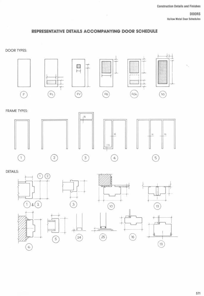
Construction Details and Finishes
DOORSHollow Metal Door Schedules
REPRESENTATIVE DETAILS ACCOMPANYING DOOR SCHEDULE

Construction Details and Finishes
DOORSHollow Metal Door Schedules

Construction Details and Finishes
DOORSHollow Metal Door Frames

Construction Details and Finishes
DOORSHollow Metal Door Frames
BASIC DOOR FRAME PROFILES AND THEIR PARTS
VERTICAL FRAME DIMENSIONS
TYPICAL BACKBEND or PLASTER STOP PROFILESHORIZONTAL
FRAME DIMENSIONS
REPRESENTATIVE FRAME PROFILES

Construction Details and Finishes
DOORSHollow Metal Door Frames
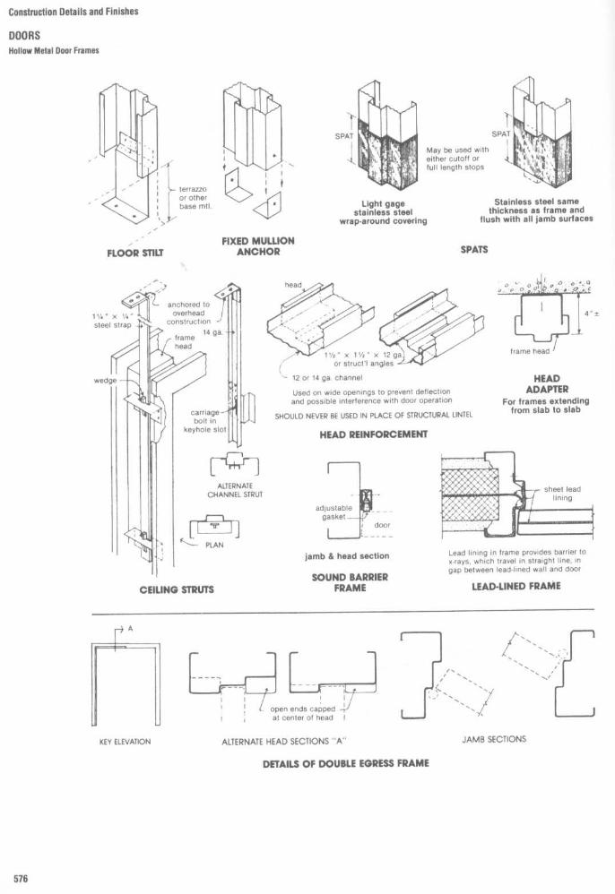
ConstructionDetailsandFinishesDOORSHollow Metal Door Frames
Stainless steel samethickness as frame and
flush with all jamb surfaces
Light gagestainless steel
wraparound covering
FIXED MULLIONANCHORFLOOR STILT
HEADADAPTER
For frames extendingfrom slab to slab
HEAD REINFORCEMENT
Lead lining in frame provides barrier tox-rays, which travel in straight line, ingap between lead-lined wall and door
LEAD-LINED FRAME
jamb & head section
SOUND BARRIERFRAMECEILING STRUTS
DETAILS OF DOUBLE EGRESS FRAME

Construction Details and Finishes
DOORSHollow Metal Door Frames

Construction Details and Finishes
DOORSHollow Metal Door Frames

Construction Details and Finishes
DOORSHollow Metal Door Frames
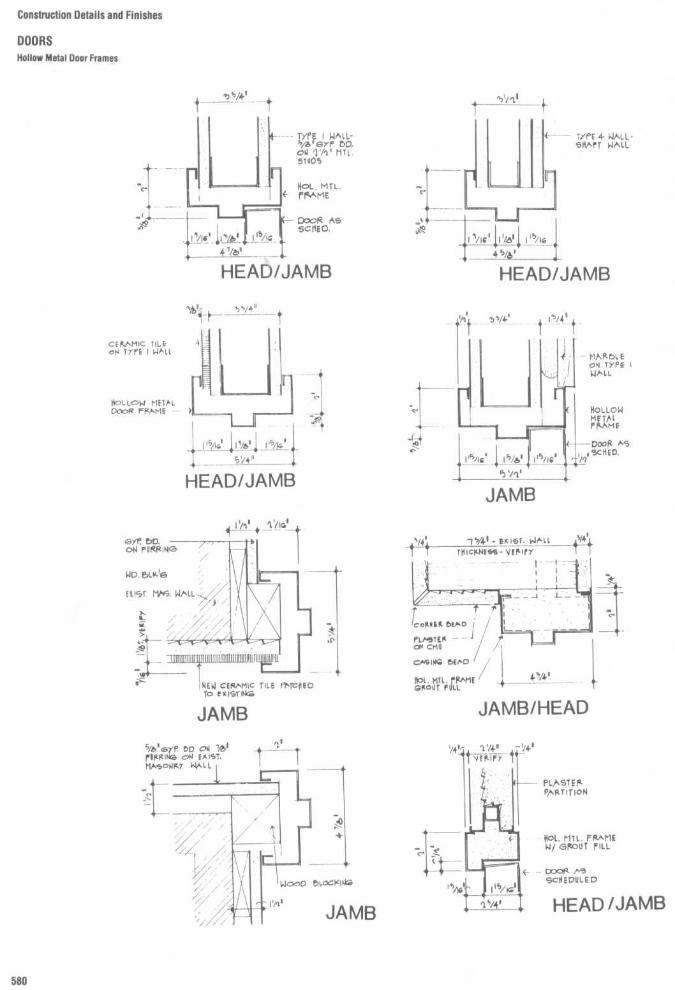
Construction Details and Finishes
DOORSHollow Metal Door Frames

Construction Details and Finishes
DOORSHollow Melal Door Frames

Construction Details and Finishes
DOORS
Hollow Metal Door Frames

Construction Details and Finishes
DOORSHollow Metal and Wood Door Frames

Construction Details and Finishes
DOORS
Hallow Metal and Wood Door Frames

Construction Details and Finishes
DOORSHollow Metal and Wood Door Frames

Construction Details and Finishes
DOORSHollow Metal and Wood Door Types

Construction Details and Finishes
DOORSDoor Types

Construction Details and Finishes
DOORS
Door Types

ANCHORHINGEHeavy weight hinge with each leaf ex-tended at its top edge and bent to forma flange that fastens to top edge ofdoor and to frame head rabbet . May beused as top hinge on heavy doors anddoors having high frequency usage .
FULL MORTISE BUTT HINGETwo equal square-edged leaves, onemortised into door edge, the other intoframe rabbet .Two bearings, as shown, on regularweight hinges, four on heavy weight .
Typical Uses :By far the most common type of hingefor both interior and exterior hollowmetal and wood swing doors, in alltypes of buildings .
Usual Sizes (see NOTE below) :heights-41/2 "; 5" for doorsover36"w .widths - 4 1/2 " for 1 1/4 " door and 1 Yx "trim clearance (dimension A); 5" (ormore) for thicker doors or largerclearances .
HALF MORTISE BUTT HINGEOne square-edged leaf mortised in-to door edge ; the other leaf, bevel-edged, mounted on face of frame .
Typical Uses :Used with hollow metal orkalamein doors in struc-tural channel frames,usually in industrial typebuildings .
Usual Sizes :4'/~ ", 5" and 6" heights.
docedçlea
HALF SURFACE BUTT HINGEOne leaf, bevel-edged, mounted onface of door; the other leaf, square-edged, mortised into frame rabbet .Typical Uses :Used with hollow metal or kalameindoors in hollow metal frames, usuallyin industrial buildings . Heavy weighttype also used on lead-lined doors .Usual Sizes : 4Ys ", 5" and 6" heights .
FULL SURFACE BUTT HINGETwo bevel-edged leaves of differingwidths, one surface-mounted on doorface, the other on frame face .Typical Uses:Used with hollow metal or kalameindoors in structural channel frames, inindustrial buildings . Heavyweight typemay be used on lead-lined doors .Usual Sizes : 4 1/2 ", 5" and 6" heights .
NOTE : Anchor hinges and pivot hinges should be specified for heavy doorsand doors with high frequency use, such as entrances to large departmentstores, office buildings, theaters, banks and schools, or to toilet rooms inschools and airport buildings . Regular weight hinges may be specified fordoors with average and low frequency uses such as corridor doors in publicbuildings and doors in residential buildings .
THRUST PIVOTUNIT AND HINGE SETPivot unit for top of door, with bothjamb and top plates for both door andframe . Used, with conventional butthinges, on wide doors that may be sub-jected to abnormal abuse . The hinge isalmost invisible when door is closed .
Construction Details and Finishes
DOORSHollow Metal Door Hardware : Hinges
PIVOTREINFORCEDHINGEHeavy weight hinge with added pivoton the same pin . Leaves of pivot are in-terlocked with hinge leaves . Used withconventional butt hinges on doors sub-ject to abnormal abuse, particularlywith overhead closers .
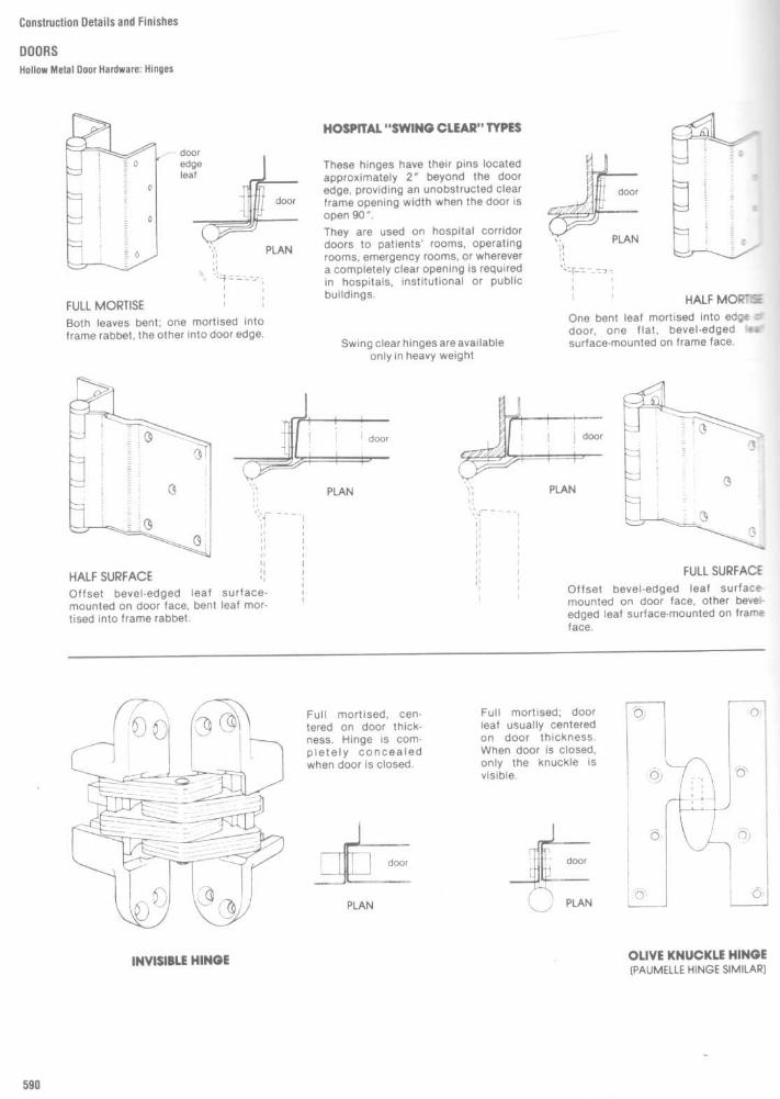
Construction Details and Finishes
DOORSHollow Metal Door Hardware : Hinges
HOSPITAL "SWING CLEAR" TYPES
These hinges have their pins locatedapproximately 2" beyond the dooredge, providing an unobstructed clearframe opening width when the door isopen 90" .They are used on hospital corridordoors to patients' rooms, operatingrooms, emergency rooms, or wherevera completely clear opening is requiredin hospitals, institutional or publicbuildings.
OLIVE KNUCKLE HINGE(PALIMELLE HINGE SIMILAR)INVISIBLE HINGE
Full mortised ; doorleaf usually centeredon door thickness .When door is closed,only the knuckle isvisible .
Full mortised, cen-tered on door thick-ness . Hinge is com-pletely concealedwhen door is closed .
FULL SURFACEOffset bevel-edged leaf surface-mounted on door face, other bevei-edged leaf surface-mounted on frameface .

Construction Details and Finishes
DOORS
Hollow Metal Door Hardware : Pivots
Pivots are stronger and more durable than hinges and are better able towithstand the racking stresses to which doors are subjected. Their use isgenerally recommended on oversize doors, on heavy doors such as lead-lined doors, and on entrance doors to public buildings such as schools,theaters, banks, store and office buildings.NOTE : Because of adjustments that must be made during the installationof doors with bottom pivots, it is recommended that reinforcements be fur-nished in blank and that drilling and tapping be done in the field by the con-tractor .
OFFSET TYPEUsed on single-acting doors only. Need for in-termediate pivot depends upon the size, weightand usage of door ; recommendation of hardwaremanufacturershould be followed . Pivot knucklesvisible when door is closed .
CENTER TYPEUsed at top and bottom of double-acting doorsonly. Pivots are completely invisible when door isclosed .

Construction Details and Finishes
DOORSHallow Metal Door Hardware
LOCKS, LATCHES, AND DEADLOCKS
The selection of the proper lock type is veryimportant . The types shown here are thosemost commonly used, but are by no meansthe only types available . Thei r names serve toidentify eitherthetypeof lock construction orthe type of installation . Mortise locks providethe greatest variety of lock functions, thebest security, and excellent durability. An-other popular type, with rugged constructionand easily operated, is the preassembledlock, which is completely assembled at thefactory. It does not have as many lock func-tions as the mortise lock, but can have aseparate deadbolt . The bored lock is the leastsecured type and is not available with aseparate deadbolt in the lock .
BORED (CYLINDRICAL) LOCKThis type of lock uses the key-in-the-knob principle . It is in-stalled in a door having one hole bored through the thicknessof the door and another bored in from the edge. The assemblymust be tight on the door, without excessive play, to avoidbinding .
The mortise lock is so named because it is installed in aprepared recess (mortise) in the door . Working parts are con-tained in a rectangular case with holes for cylinder and knobspindle . Anti-friction split bolts are available for smoothretraction of the lock bolt . Lock front may be armored to pro-tect against burglars getting at cylinder screws and lockfasteners . Lever handles may be used if desired, and trim maybe either sectional or full plate.
UNIT LOCKThis lock is preassembled in the factory and consists of a one-piece extruded or cast brass frame within which all parts arecontained . It is installed in a rectangular reinforced notch cutin the door edge . Lever handles may be used in place of knobs .
MORTISE LOCK
This is a mortise lock with a deadlock only . (A deadlock is alock bolt which has no bevel or spring action, and is operatedby a key or thumb turn .) It is often used for locking a door hav-ing push or pull plates or for providing added security ondoors with cylindrical locks .
MORTISE DEADLOCK
BORED (CYLINDRICAL) DEADLOCKThis is a cylindrical type of lock having a deadbolt only . It fitsinto the same type of cylindrical cutout as that required for thebored lock .

Construction Details and Finishes
DOORSHollow Metal Door Hardware : Overhead Closers

Construction Details and Finishes
DOORS
Hollow Metal Door Hardware : Floor Closers
OVERHEAD AND FLOOR CLOSERS
Overhead closers (Figs. 3 to 8) are hydraulicdevices, containing a piston, fluid chambers,and a spring . When the door is opened thepiston is pulled back, the spring is com-pressed, and the fluid is movedfrom one sideof the piston to the other. With release of thedoor a reverse action takes place, closing thedoor Closing speed is controlled byan adjust-able valve or valves . Overhead closers maybe installed on either single-or double-actingdoors .
Floor closers, generally more durable thanoverhead closers, provide concealed closingmechanisms often appropriate for doors hav-ing a high frequency of use. As shown, thetype of closer used depends on whether thedoor is hung on hinges, offset pivots, orcenter pivots .
Both overhead and floor closers are avail-able in a range of sizes for various door sizes,locations, and job conditions . The manufac-turer's recommendations should always befollowed in determining which size and typeshould be used .Wheresurface-mounted closers are spec-
ified, internal reinforcement plates shall beprovided in the door and frame by the manu-facturer. Drilling and tapping for the closershall be done in the field by the installer. Onlyafter the door is installed and adjusted canthe closer be mounted for proper operationIf drilling and tapping have been done at thefactory, the necessary field adjustments be-come difficult if not impossible .

Construction Details and Finishes
DOORS
Hallow Metal Door Hardware
3%NIC AND FIRE EXIT HARDWARE
Npes of Installation
manic hardware is tested and labeled forasualty only, fire exit hardware for bothasualty and fire resistance . Only the latter-ay be used where fire rated doors are-pquired. Both types are always releasable-om the inside by depressing the crash barne mortise type (Fig . 9) and the concealed.ertical rod type (Fig . 10) are the least con-scicuous, and either of these types is readilyapplicable to custom hollow metal doors.Rim and mortise types are used onSingle doorActive door of pairBoth doors of pairwith mullion
2rtical rod types are used onSingle doorActive door of pairBoth doors of pair
Where rim type (Fig .11) or exposed vertical-ad (Fig . 12) exit devices are specified, inter-nal reinforcement plates shall be provided in-+e door and frame by the manufacturer.Dnlling and tapping for trim and mounting-gates shall be done in the field by therstaller The hardware can then be more-eadily adjusted for best operation.
In preparing the door for a lock, the drilling_~ three bolt holes (Yz' dia. or less) and/or the,i-iling and tapping for sectional or full trim=,ates shall be done in the field by therstaller and not at the factory. After the locks installed and adjusted, the trim plate can beapplied to suit the final position of the latch-ing device . If thru bolt holes or tapped holesare provided at the factory, this adjustmentBecomes difficult if not impossible .The manufacturer shall drill for all function
Holes, i .e ., cylinder, turn piece, and knob .
Door Coordinators
Zoordinators (Figs . 13 and 14) are used onzairs of doors having overlapping astragalsand closers. When both leaves are open, the:oordinator holds the active leaf open untilTe inactive leaf is closed, preventing inter-'aences of the astragal .

Construction Details and Finishes
DOORS
Follow Metal Door Hardware
FLUSH BOLTS
These bolts are installed on the inactive leafof a pair of doors to secure it in the closedposition to serve as a latching point for theactive leaf . They may also be used as auxiliarylocking devices for added security Bolts maybe either surface-mounted or flush (con-cealed rod) ; only the latter type is illustratedin Fig. 15 .There are many variations of these flush
bolts; only the more common types beingshown in Fig . 15 . Due to the variety of frame
construction encountered, the selection ofthe most appropriate type of strike is particu-larly important, and clearance at the floormust be very carefully controlled to insureproper engagement .The manual type (Fig . 15A) requires hand
operation of the operating lever for bothlatching and unlatching . The variable lengthof the extension rod, however, permits con-venient location of the operating mechanismin the door edge . The self-latching types
(Fig . 15B and C) latch automatically wnarthe inactive leave is closed, but must meunlatched manually. The automatic(Fig . 15D) both latches and unlatches a,.=-matically when the inactive leaf is closes oropened .None of these types of flush bolt shoulc
used on doors that are intended to serveemergency exists . N FPA pamphlet80 shc~cbe consulted for the selection of bolts for f,rerated pairs of doors.
MANUAL TYPE SELF-LATCHING TYPES
U.L .-APPROVED BOUS ARE REQUIRED AT BOTH TOP AND
BOTTOM OF INACTIVE LEAF OR FIRE-RATED PAIRS OF DOORS
Fig.15
Except for Type C, only top bolts are shown; bottom bolts are similar in all cases.
AUTOMATIC TYPE

Construction Details and Finishes
DOORSDoor Hardware
OVERHEAD DOOR HOLDERS
These are devices used to limit and control the swing of thedoor or hold it in the open position . By controlling the dooraction they serve to protect against damage to the doorand/or hinges caused by abusive usage, and damage tothe holder caused by violent opening of the door .
HOSPITAL DOOR LATCH
Designed primarily for use in hospitals, on corridordoors leading to patient rooms . May also be used onany door requiring push-pull operation, particularlyby forearmor elbow, when hands are engaged in car-rying objects .
EMERGENCY DOOR STOP
Intended primarily for use in hospitals, on doors between pa-tient rooms and toilets . This stop permits door to be openedfrom the stop side in the event that an incapacitated patientshould block the normal swing by falling . Door must be hungon center (double-acting) pivots .

Construction Details and Finishes
DOORSHardware Locations

Construction Details and Finishes
DOORSHollow Metal Door Edge Treatments

Construction Details and Finishes
DOORS
Fire-Protecled Wood Doors

Construction Details and Finishes
DOORSSliding Glass and Aluminum Doors

Construction Details and Finishes
DOORSThresholds
Thresholds are essential for nearly everytype of door . Usually a standard section issatisfactory . Where conditions require,special sections may be designed .

Construction Details and Finishes
DOORSThresholds and Joint Strips
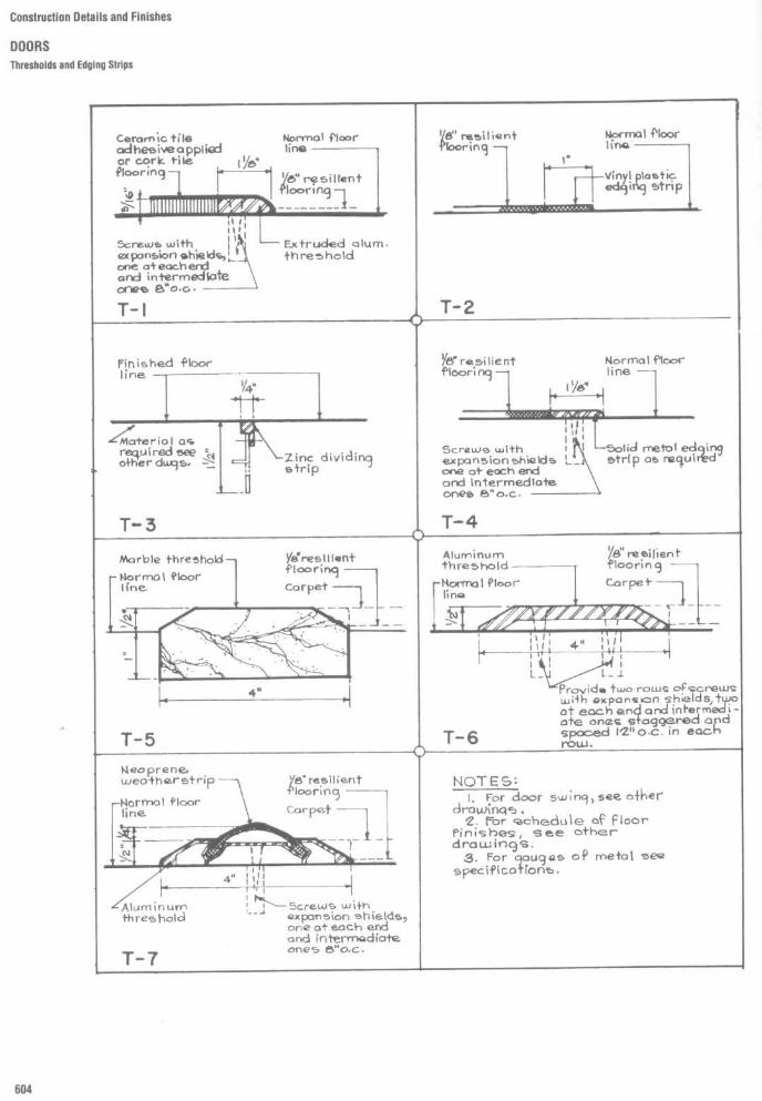
Construction Details and Finishes
DOORSThresholds and Edging Strips

Construction Details and Finishes
DOORSBank Vault Doors

Construction Details and Finishes
DOORS
Light- and Soundprooling of Wood and Hollow Metal Door Frames

Construction Details and Finishes
DOORSHallow Metal Door Frames
The prime functions of the door frame arelo hold the door and its controls in themening, and to trim the opening. But frames-ten serve other esthetic or functional pur-noses also, such as trimming a wall openingwing no door, or enclosing glazed areas thatprovide through-wall visibility or admittinggnt and/or air. Hollow metal frames, whichare strong, sturdy, and durable, serve all such~,nctions economically.The variety of configurations available in
nistom hollow metal frames is virtually un-imited . Illustrated in Fig . 16 are some of the-pore common and representative types .

Construction Details and Finishes
DOORSHollow Metal Door Frames

Construction Details and Finishes
DOORSHollow Metal Door Frames

Construction Details and Finishes
DOORSDoortypes and Construction
IIIN
N WyO4 2~. Iy
Q~O >.
~=N
2 N N NJ W y W_J I.Z LQ-7 hQH Qi t0.1 h C U~ ¢ Q .
U ~2E " O N = Qli 3 rN
V .
wv x _zQW
8bar a - Eô éE 5 .. t? x
N _ o Sôd - B A yq ° _ d3~ I s~
y8~m ~~ _- âv, ~R g ~E ~R = â
a
Wo &
âo
~<3
É o~~
É Eg= $
3
4 ~-
Qo0 -"v^~8 o3
M° I
._ â~ ~ûU
Nt~ $~u~n
8 ô .Rz s 8
Û 3 m _ÉH I - IT
~3N- W
Ô
3
JJ
- ÉE
I I
Â
â `~ 8
trn 8m
.
É
-=EÉ
__
Zâ$z
â
8
U _-Q - _
â l s3 8~
- ~ =K 3304
'
>
I4ZI¢I Q3
yQO2Qa
D

Construction Details and Finishes
DOORSSliding Doors and Handles

Construction Details and Finishes
DOORS
Door Types

Construction Details and Finishes
DOORS
Door Types
11~~
MillRail
UN
_'~I
a
I!I~ IJ I!
fm- Co:il
i
i', _I~IhI
1-
1 f l IIC
-m__
I~11_J
I~I
I.
il
la
" Il
la
I
il
ai-
à
Il

Construction Details and Finishes
DOORSWood Door Frames

Construction Details and Finishes
DOORSWood Door Frames

Construction Details and Finishes
DOORSSecret Door
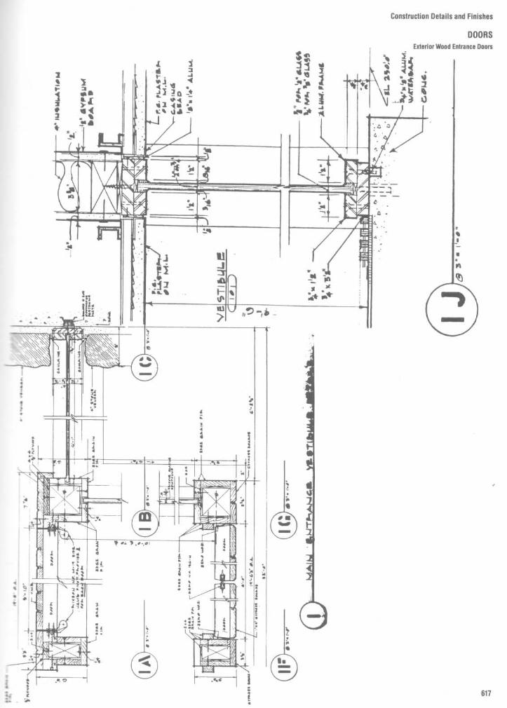
Construction Details and Finishes
DOORSExterior Wood Entrance Doors

Construction Details and Finishes
DOORS
Exterior Wood Entrance Doors

Construction Details and Finishes
DOORS
Exterior Wood Entrance Doors

Construction Details and Finishes
DOORSExterior Wood Entrance Doors
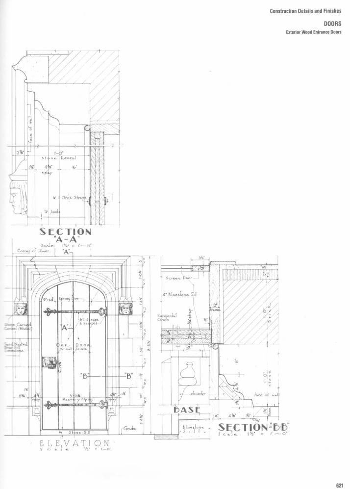
Construction Details and Finishes
DOORSExterior Wood Entrance Doors

Construction Details and Finishes
DOORSExterior Wood Entrance Doors

Construction Details and Finishes
DOORSExterior Wood Entrance Doors

Construction Details and Finishes
DOORSExterior Wood Entrance Doors

Construction Details and Finishes
DOORSExterior Wood Entrance Doors

Construction Details and Finishes
DOORSExterior Wood Entrance Doors

Construction Details and Finishes
DOORSExterior Wood Entrance Boors

Construction Details and Finishes
DOORSExterior Wood Entrance Doors

Construction Details and Finishes
DOORS

Construction Details and Finishes
DOORS
Metal Door Frames

Construclion Details and Finishes
DOORSMetal Door Frames

Construction Details and Finishes
DOORSBI-Fold Doors

Construction Details and Finishes
DOORSSliding French Door

Construction Details and Finishes
DOORSHardware
Hardware for doors may be obtained in anumber of finishes, with brass, bronze, andnickel perhaps the most common . Door set'sare usually classed as (a) entry lock forexterior doors, (b) bathroom set (inside lockcontrol with safety slot for opening from theoutside), (c) bedroom lock (keyed lock), and(d) passage set (without lock) .
HingesUsing three hinges for hanging 13/4-in exteriordoors and two hinges for the lighter interiordoors is common practice . There is sometendency for exterior doors to warp duringthe winter because of the difference inexposure on the opposite sides . The threehinges reduce this tendency Three hingesare also useful on doors that lead to unheatedattics and for wider and heavier doors thatmay be used within the house .
Loose-pin butt hinges should be used andmust be of the proper size for the door theysupport . For 1 3/4-in-thick doors, use 4- by 4-inbutts ; for 1 1/8-in doors, 3'/z- by 31/2-in butts .After the door is fitted to the framed opening,with the proper clearances, hinge halves arefitted to the door. They are routed into thedoor edge with about a 3-16"-in back distance(Fig . 26A) . One hinge half should be set flushwith the surface and must be fastenedsquare with the edge of the door. Screws areincluded with each pair of hinges .

Construction Details and Finishes
DOORSHand of Locks; Lock Functions
Locks not designated as reversible aremade right-hand, left-hand, right-hand re-verse bevel, or left-hand reverse bevel .The hand of a lock is invariably determined
from the outside of an entrance door or fromthe corridor or hall side of a room door. Aneasy method of determining the hand of alock is to imagine oneself on that side of theopening from which the lock is controlled oroperated by the key Viewing the opening inthis position, note which one of the followingis true : (1) If the door swings in and is hingedat your right hand, the lock is right-hand ; (2) ifhinged at your left hand, the lock is left-hand ;(3) if the door swings toward you and ishinged at your right, the lock is right-handreverse bevel; (4) if hinged at your left hand,the lock is left-hand reverse bevel.You may find that many locks are marked
"reversible;' meaning that they are inter-changeably right- or left-hand, and in theseinstances no reference to hand or bevel oflock is necessary. These are locks whichoperate alike from both sides or locks whichcan be inverted in order to reverse thelocking functions .

Construction Details and Finishes
DOORSLock Functions
OFFICEFor Inner Office and Area EntryDoors." Latchbolt retracted by lever or knobfrom either side unless outside islocked by stop button .
" When outside is locked, Latchbolt isretracted by key outside and leveror knob inside .
" Auxiliary latch deadlocks Latchboltwhen door is closed .
" Latch holdback available
APARTMENT ENTRANCEFor Apartment House or OfficeBuilding Entrance Doors" Latchbolt retracted by lever or knobeither side unless outside is lockedby key from inside .
" When locked, Latchbolt retractedby tenant key outside, lever orknob inside .
" Auxiliary latch deadlocks Latchboltwhen door is closed .
INSTITUTIONFor Permanently Locked PassageDoors." Latchbolt retracted by key fromeither side .
" Both levers or knobs alwaysinoperative .
" Auxiliary latch deadlocks Latchboltwhen door is closed .
" Latch holdback available .
STORE DOORFor Store Entrance Doors." Latchbolt retracted by lever or knobfrom either side unless outside islocked by stop button .
" When locked Latchbolt retracted bykey outside and lever or knob inside -
" Deadbolt operated by key fromeither side .
" Auxiliary latch deadlocks Latchboltwhen door is closed .
STORE DOORFor Storedoor, Storeroom orUtility Room Doors." Latchbolt retracted by lever or knobfrom either side .
" Deadbolt operated by key fromeither side .
CYLINDER X TURN PIECEDeadlock" Deadbolt operated by key outsideand turn inside
DOUBLE CYLINDERDouble Cylinder Deadlock" Deadbolt operated by key fromeither side .
" Bolt automatically deadlocks whenfully thrown .
CLASSROOMClassroom Deadlock" Deadbolt operated by key outside ." Cylinder turn inside will retractdeadbolt but will not project it .
" Bolt automatically deadlocks whenfully thrown .
CYLINDER X BLANKDeadlock" Deadbolt operated by key fromone side .
" No trim on opposite side ." Bolt automatically deadlocks when
fully thrown .
CLASSROOM" Latchbolt retracted by lever or knobfrom either side unless outside islocked by key .
" Inside lever or knob always free forimmediate exit .
" Auxiliary latch deadlocks Latchboltwhen door is closed .
STOREROOM" Latchbolt retracted by lever or knobinside, by key outside .
" Outside lever or knob alwaysinoperative . Knob is free spinning .
" Auxiliary latch deadlocks Latchboltwhen door is closed .
" Latch holdback available .ENTRANCEFor Commercial and ResidentialEntry Doors" Deadbolt and Latchbolt retracted bylever or knob trim either side unlessoutside is locked by stop button .
" When locked, key outside and leveror knob inside retracts deadbolt andLatchbolt simultaneously . Outsideremains locked until stop button isreset to unlocked position .
" Deadbolt operated by key and turnpiece . Throwing deadbolt automati-cally locks stop button .
" Auxiliary latch deadlocks Latchboltwhen door is closed and locked .
CONVALESCENTFor Convalescent or BedroomDoors" Latchbolt retracted by lever or knobfrom either side when unlocked .
" Deadbolt operated by key outsideand turn piece inside .
" Throwing deadbolt disengagesoutside lever or knob .
" Turning inside lever or knob retractsdeadbolt and Latchbolt simultane-ously for immediate exit and unlocksoutside .
CLOSETFor Closet, Storeroom, or UtilityRoom Doors" Latchbolt retracted by lever or knobfrom either side at all times.
" Deadbolt operated by key outside .
DORMITORYFor Dormitory or Bedroom Doors ." Latchbolt retracted by lever or knobfrom either side at all times .
" Deadbolt is operated by key outsideand by turn piece inside .
HOTELFor Corridor Doors to GuestRooms." Outside lever or knob alwaysinoperative . Knob is free spinning .
" Latchbolt retracted by guest keyoutside except when deadbolt isthrown by turn piece inside .
" When thrown occupancy indicatoris engaged, all keys inoperativeexcept emergency or display keys .
" Turning inside lever or knob retractsdeadbolt and Latchbolt simultane-eously. Aux. latch deadlocks latch-bolt when door is closed .HOTELFor Corridor Doors to GuestRooms" Same as 85P function except thatvisual "DO NOT DISTURB" platereplaces occupancy indicatorbutton .
Available for 1 3/4" doors and escutch-eon trim only.

Construction Details and Finishes
DOORSLock Functions
ANSI A 156.2Non-KeyedLocks Series 4000Passage Latch : Both knobs alwaysunlocked
Exit Lock: Unlocked by knob inside only.Outside knob always fixed .
Closet Latch: Outside knob and insidethumbturn are always unlocked .
Exit Lock: Blank plate outside . Insideknob always unlocked . (Specify doorthickness, 1 3/e" or 1 3/a" .)
Patio Lock. Push-button locking . Turninginside knob releases button . Closing dooron A & D series also releases button .
Bath/Bedroom Privacy Lock: Push-button locking . Can be opened from out-side with small screwdriver or flat narrowtool . Turning inside knob releases push-button . Closing door on A, C and D seriesalso releases button, preventing lock-out .
Communicating Lock: Turn button inouter knob locks and unlocks knob andinside thumbturn .
Hospital Privacy Lock: Push-button lock-ing . Unlocked from outside by turningemergency turn-button . Rotating insideknob or closing door releases insidebutton .
Dummy TrimSingle Dummy Trim: Single dummy trimfor one side of door. Used for door pull oras matching inactive trim .
ANSIA 156.2KeyedLocks
Series 4000Entrance Lock. Unlocked by key fromoutside when outer knob is locked byturn-button in inside knob . Inside knobalways unlocked .Entrance/Office Lock: Push buttonlocking . Pushing button locks outsidelever until unlocked with key or by turn-ing inside lever.
Entrance Lock. Turn/Push buttonlocking : Pushing and turning buttonlocks outside knob requiring use of keyuntil button is manually unlocked .Push button locking : Pushing buttonlocks outside knob until unlocked by keyor by turning inside knob.Service Station Lock: Unlocked by keyfrom outside when outer knob is lockedby universal button in inside knob . Clos-ing door releases button . Outside knobmay be fixed by rotating universalbutton .Vestibule Lock: Unlocked by key fromoutside when outside knob is locked bykey in inside knob . Inside knob is alwaysunlocked .Store Lock: Key in either knob locks orunlocks both knobs .
Classroom Lock: Outside knob lockedand unlocked by key. Inside knob alwaysunlocked .
Communicating Lock: Key in eitherknob locks or unlocks each knobindependently.
Dormitory Lock: Locked or unlocked bykey from outside . Push-button lockingfrom inside. Turning inside knob or clos-ing door releases button .
Classroom Hold-Back Lock: Outsideknob locked or unlocked by key. Insideknob always unlocked . Latch may belocked in retracted position by key.

Construction Details and Finishes
DOORSLock Functions
ANSIA 156.2KeyedLocks
Series 4000Communicating Lock: Locked orunlocked by key from outside . Blankplate inside.
Storeroom Lock: Outside knob fixed .Entrance by key only. Inside Knob alwaysunlocked .
Institution Lock: Both knobs fixed .Entrance by key in either knob .
Hotel-Motel Lock: Outside knob fixed .Entrance by key only. Push-button ininside knob activates visual occupancyindicator, allowing only emergencymasterkey to operate . Rotation of insidespanner-button provides lockout featureby keeping indicator thrown .
Deadbolt Locks ANSI A 156.5Single Cylinder Deadbolt Lock: Deadboltthrown or retracted by key from outsideor by inside turn unit . Bolt automaticallydeadlocks when fully thrown .
Double Cylinder DeadboltLock:Deadbolt thrown or retracted by keyfrom either side .
One-Way Deadbolt Lock: Deadboltthrown or retracted by key only. Blankplate inside .
Classroom Deadbolt Lock: Deadboltthrown or retracted by key outside .Inside turn unit will retract bolt only .
Cylinder Lock: Deadbolt thrown orretracted by key from one side . Noinside trim .
Door Bolt: Deadbolt thrown or retractedby turn unit only. No outside trim .
Deadlatch Locks ANSI A1563
Night Latch: Deadlocking latchboltretracted by key from outside or byinside turn unit . Rotating turn unit andactivating hold-back feature keeps latchretracted .Double Cylinder Deadlatch: Deadlockir~ :latchbolt retracted by key from eitherside . No hold-back feature .
ExitLatch: Deadlocking latchboltretracted by inside turn unit only. Nooutside trim . Rotating turn unit andactivating hold-back feature keepslatch retracted .
Lever FunctionsLever Passage Latch : For use on passaç=closet and doors that do not require locking . Rotating either lever retracts latch-bolt . (Specify door hand .)
Single Dummy Trim-Double DummyTrim : For use on single or pairs of doorswhen fixed turn is required . (Specify doorhand .)
Grip Handle SetsEntrance Lock: Unlocked by key fromoutside when thumb-piece is locked byinside turn-button .
Entrance Lock: Deadbolt thrown orretracted by key from outside or by insideturn unit . Latch retracted by thumbpiecefrom outside or by inside knob .
Double Cylinder Entrance Lock:Deadbolt thrown or retracted by keyfrom either side . Latch retractedby thumbpiece from outside or byinside knob .
tCAUTION : Double cylinder locks onresidences and any door in any structurewhich is used for egress are a safety haz-ard in times of emergency and their use isnot recommended . Installation should bein accordance with existing codes only.

Construction Details and Finishes
DOORSLock Functions
Dummy TrimOutside and Inside Dummy Trim: Foruse as door pull or as dummy trim onan inactive of pair of doors . Fixed thumb-piece and inside knob . Thru bolteddummy cylinder.Outside andInside Dymmy Trim : For useas door pull or as dummy trim on inactiveleaf of pair of doors . Fixed thumbpieceand inside knob . Dummy cylinder withinside plate .
InterconnectedLocks
ANSI A156.12Entrance-Single Locking: Deadboltthrown or retracted by key in upper lockfrom outside or by inside turn unit . Latch-bolt retracted by knob from either side .Turning inside knob retracts deadbolt andlatchbolt simultaneously for immediateexit .Entrance-Double Locking: Deadboltthrown or retracted by key in upper lockfrom outside or by inside turn unit . Dead-latch retracted by key in outer knob whenlocked by pushing turn-button in innerknob . Outer knob may be fixed in lockedposition by rotating turn-button . Insideknob retracts deadbolt and deadlatchsimultaneously for immediate exit .Storeroom Lock: Bolt may be operatedby key from outside or by turn unit frominside . Bolt automatically deadlockswhen fully thrown . Lock may be openedby key from outside . Inside knob willretract both latch and deadbolt . Latchautomatically deadlocks when door isclosed, inside knob always free for imme-diate exit . Outer knob always fixed .Hotel-Motel Lock: Deadbolt thrown orretracted by key in upper lock from out-side or by inside turn unit . Deadlatchretracted by key in outer fixed knob .Push-button in inner knob activatesvisual occupancy indicator, allowing onlyemergency masterkey to operate . Rota-tion of inside spanner-button provideslockout feature by keeping indicatorthrown . Turning inside knob retractsdeadbolt simultaneously for immediateexit .
Dummy TrimSingle Dummy Inside Trim : Snap-on roseand knob . Concealed mounting screws.
Dummy Trim Inside and Outside:Snap-on rose and knobs thru-bolted .
Mortise LockS
ANSI A156.13Non-Keyed
Series 1000Passage Latch: Latch bolt retracted bylever or knob from either side at all times .
Bath/Bedroom Privacy Lock: Latchboltretracted by lever or knob from eitherside unless outside is locked by insideturn piece . Operating inside lever or knobor closing door unlocks outside lever orknob . To unlock from outside, removeemergency button, insert turn piece(furnished) in access hole and rotate.Single Dummy Trim: Lever or knob onboth sides fixed by mounting bar.
Pair Dummy Trim: Lever or knob on bothsides fixed by mounting bar.
Single Dummy Trim: Lever or knob onone side fixed . Includes lock chassis andarmor front .
Pair Dummy Trim: Lever or knob bothsides fixed . Includes lock chassis andarmor front .
KeyedLocksOffice and Inner EntryLock: Latchboltretracted by lever or knob from eitherside unless outside is made inoperativeby key outside or by rotating inside turnpiece . When outside is locked, latchboltis retracted by key outside or by leveror knob inside . Outside lever or knobremains locked until thumbturn isreturned to vertical or by counter clock-wise rotation of key. Auxiliary latch dead-locks latchbolt when door is closed .Apartment Entrance Lock: Latchboltretracted by lever or knob from eitherside unless outside is locked by key frominside . When locked, latchbolt retractedby key outside or lever or knob inside .Auxiliary latch deadlocks when door isclosed .Classroom Lock: Latchbolt retracted bylever or knob from either side unless out-side is locked by key. Unlocked from out-side by key. Inside lever or knob alwaysfree for immediate exit . Auxiliary latchdeadlocks latchbolt when door is closed .
**When armored front is required asstrike for inactive door, specify L9177for single or L9178 for pair of dummytrim . Specify door hand .

Construction Details and Finishes
DOORSLock Functions
KeyedLocksStoreroom Lock : Latchbolt retracted bykey outside or by lever or knob inside.Outside lever or knob always inoperative .Auxiliary latch deadlocks latchbolt whendoor is closed .
Storeroom Lock: Electrically locked .Outside lever or knob continuouslylocked by 24V AC or DC . Latchboltretracted by key outside or by lever orknob inside . Switch or power failureallows outside lever or knob to retractlatchbolt . Auxiliary latch deadlocks latch-bolt when door is closed . Inside lever orknob always free for immediate exit .Storeroom Lock: Electrically unlocked .Outside lever or knob unlocked by 24VAC or DC . Latchbolt retracted by keyoutside or lever or knob inside . Auxiliarylatch deadlocks latchbolt when door isclosed . Inside lever or knob always freefor immediate exit .Institution Lock: Latchbolt retracted bykey from either side. Lever or knob onboth sides always inoperative . Auxiliarylatch deadlocks latchbolt when door isclosed .Entrance Lock: Latchbolt retracted bylever or knob from either side unless out-side is locked by 20° rotation of thumb-turn . Deadbolt thrown or retracted by90° rotation of thumbturn . When locked,key outside or lever or knob insideretracts deadbolt and latchbolt simul-taneously. Outside lever or knob remainslocked until thumbturn is restored to ver-tical position . Throwing deadbolt auto-matically locks outside lever or knob .Auxiliary latch deadlocks latchbolt whendoor is closed .Dormitory/Exit Lock : Latchbolt retractedby lever or knob from either side . Dead-bolt thrown or retracted by key outside orinside thumbturn . Throwing deadboltlocks outside lever or knob . Rotatinginside lever or knob simultaneouslyretracts deadbolt and latchbolt, andunlocks outside lever or knob .Closet/Storeroom Lock: Latchboltretracted by lever or knob from eitherside except when deadbolt is extended .Deadbolt extended or retracted by keyoutside .Store/Utility Room Lock: Latchboltretracted by knob or lever from eitherside except when deadbolt extended .Deadbolt extended or retracted by keyfrom either side .Dormitory/Bedroom Lock: Latchboltretracted by knob or lever from eitherside except when deadbolt is extended .Deadbolt extended or retracted by keyoutside or thumbturn inside .
KeyedLocksHotel Lock : Latchbolt by key outside orby lever or knob inside . Outside lever orknob always fixed . Deadbolt thrown orretracted by inside thumbturn . Whendeadbolt is thrown, all keys becomeinoperative except emergency or dispwkeys . Turning inside lever or knob retracesboth deadbolt and latchbolt simultane-ously . Auxiliary latch deadlocks latchbolltwhen door is closed .Hotel Lock: Latchbolt retracted by keyoutside or by lever or knob inside . Out-side lever or knob always fixed . Deadbd2thrown or retracted by inside thumbtL-- .When deadbolt is thrown, "DO NOTDISTURB" plate is displayed-all keysbecome inoperative except emergent .or display keys . Turning inside lever orknob retracts both deadbolt and latchbotsimultaneously. Auxiliary latch deadlockslatchbolt when door is closed .
DeadlocksCylinderX Thumbturn: Deadbolt throrn -or retracted by key outside or thumbtunrinside .
Double Cylinder: Deadbolt operated bykey from either side .
Classroom Lock : Deadbolt thrown orretracted by key from outside. Insidecylinder turn retracts deadbolt but can-not project it .
Cylinder Lock: Deadbolt thrown orretracted by key from one side . No trimon opposite side .

Construction Details and Finishes
CEILINGSSuspension System types
This section provides the designer withrdormation on both suspended ceilings andakngs directly attached to the structure;Dove . It starts with a review of genericsspension systems and then provides de-ais and discussion of the various suspended:eAng types .Large-scale details show how, in additionstandard acoustical tiles, other ceiling
Taterials such as plaster, metal panels, baf-ihes, gypsum board, and wood can be at-VMed to suspension systems . A variety of
unusual conditions are also detailed, includ-ing curved and vaulted ceilings, wall condi-tions, light coves, and lighting fixtureframing .The designer is cautioned that in many
jurisdictions, suspension systems must at-tain a higher level of structural integrity thanmostotherarchitectural elements . For exam-ple, wire hangers may not be an acceptablemethod of suspending channels from thestructure above . Rather, steel rods of aminimum diameter or flat bar hangers of a
minimum width and thickness may be re-quired . Local or state codes should alwaysbe consulted prior to finalizing such details .
In many situations, the ceiling "skin" takeson further importance beyond aesthetic,acoustical, or visual requirements . It can alsobe used to complete an envelope that pro-vides a fire-resistive rating to the structuralmembers above . Again, it is necessary tothoroughly investigate the building and firecodes that might govern ceiling design .

Construction Details and Finishes
CEILINGSSuspension System Types

Construction Details and Finishes
CEILINGSSuspension System types

Construction Details and Finishes
CEILINGSGypsum Board Suspended Ceilings
ASSEMBLY
GYPSUM BOARD, ATTACHED
DIRECT TO FRAMING
REMARKS
" secured directly to framingmembers or to solid furring .
" most widely used in residentialand light commercial con-struction .
" two layers may be required for animproved fire resistance rating orfor better resistance to soundtransmission .
" directly affected by deflectionand/or expansion Icontraction insupporting framing .
" hat-shaped or resilient channelsmay be used .
" furring will minimize effects ofdeflection and expansion/contraction in framing uponmembrane .
" resilient channels also used toimprove resistance to soundtransmission .
" furring will also minimize effectsof streaking due to temperaturedifferential which may occur withdirect attachment .
" when framing is spaced morethan 24 inches on centers, orwhen a plenum space formechanical /electrical servicelines is required, a suspen-sion/support system consisting ofwood or metal sections or specialnailing channels is generallyprovided .
" prefabricated metal suspensionsystems are available .
" primary suspension system mayalso include a secondary systemof furring channels used to alignthe primary system and/or toprovide resilient mounting of themembrane .
" it is a high cost assembly and notwidely used .
" resilient furring channelsgenerally used with wood framing .

REMARKS
" metal or gypsum lath secureddirectly to framing .
" membrane will be directly af-fected by deflection and/or ex-pansion/contraction in supportingframing .
" metal lath may be backed formachine application of plaster .
" fire resistance ratings for differentassemblies have beenestablished .
" furring channels secured toframing, lath supported by furring .
" furring will minimize effects ofdeflection and expansion/contraction upon1membrane .
" large areas of membrane shouldhave expansion joints and shouldnot be restrained at the perimeter .
" corners of openings in gypsumlath membranes should havemetal lath reinforcing .
" suspended membrane with furringchannels only is similar to furredmembrane except that furringchannels are suspended from,rather than directly attached to,framing members .
" suspension of membrane may bea requirement in some fireresistance rated floor orroof /ceiling assemblies .
" spacing of hangers is quite closeand limits the size and/or extentof mechanical/electrical servicelines in plenum space .
" when spacing of framing is wideand/or the number of hangersmust be reduced, a primarysupport system consisting ofmain carrying channels may beused ; the furring channels arethen a secondary system, securedto such primary supports .
" for wide hanger spacing, metaljoists instead of carrying channelsmay be used .
Construction Details and Finishes
CEILINGSPlaster Suspended Ceilings

Construction Details and Finishes
CEILINGSExposed Grid Suspended Ceilings
REMARKS
" lay-in panels should be secured inplace by clips when assemblyrequires a fire resistance rating ;also against uplift due to pressuredifferential .
" fixtures generally have to beboxed-in for fire resistance ratingfire dampers must be provided atall openings, such as diffusers .
" hangers secured to framingmembers, structural deck, or tosecondary framing system .
" clearance required for all lay-inpanels for tilting them into place .
" suspension system used is thesame as for square edge tile, buttile only available in 2x2 foot size .
" may be used in fire resistance-rated floor or rooflceilingassemblies ; clips to secure tilesin place and opening protectiongenerally required .
" metal panels generally perforated .with sound absorbing blankets .
" plastic panels generally solid ;used in luminous ceiling in-stallations .
" corrugated/ribbed metal or plasticpanels generally used with mainrunners only .
" flat plastic panels generally either2x4 or 2x2 feet in size, used withmain runners and cross tees .
" flat pre-assembled modules arealso available .
" when pressurized plenum andventilating tile are used, air returnmust be ducted through plenum .
" with ventilating plenum, dirtstreaking may result unless themembrane is made completely airtight .
" may be used in fire resistance-rated floor or roof/ceilingassemblies .

Construction Details and Finishes
CEILINGSConcealed Spline Suspended Ceilings
REMARKS
" tile may be repeatedly repaintedwithout loss in sound absorbingcharacteristics .
" heating/cooling piping may beincorporated into the system .
" combination lighting/infra-redheating fixtures may be integratedinto membrane .
" secondary suspension systemgenerally required .
" tile may be used for supply/returnair .
" formed prefinished metal panelsin long lengths .
" air supply/return and lightingfixtures may be integrated intothe system .
" may be used outdoors inprotected locations, such as largesoffits, canopies .
" some assemblies may be used asrequired components in fireresistance rated floor orroof/ceiling assemblies .
" membranes may be curved per-pendicular to direction of panels .
" baffles available in shaped metal,with or without sound absorbentmaterial cores, or in faced soundabsorbent material .
" various arrangements available,such as linear, radial, hexagonal .
" used to : provide additional soundabsorption in selected locations ;for visual interest, or to concealmechanical Ielectrical services .
" tile, generally 12x12 inches insize with kerfed edges secured inplace by main runners in onedirection, and cross tees orsplines in the other .
" secondary supports, such ascarrying channels may be used toreduce spacing of hangers toframing system .
" may be used as component in fireresistance rated floor orroof /ceiling assemblies .
" special panels available to provideaccess to plenum .

Construction Details and Finishes
CEILINGSSuspended Ceiling Types
Concealed 2-spline system withacoustical tile
Concealed 2-spline system with alu-minum-clad acoustical tile
Suspended plaster ceiling
Suspended ceiling with gypsumboard
Suspended ceiling with plywoodfinish

Construction Details and Finishes
CEILINGSSuspended Ceiling Types

Construction Details and Finishes
CEILINGSSuspended Calling Types

Construction Details and Finishes
CEILINGSCurved Ceiling with Recessed Lighting

Construction Details and Finishes
CEILINGSVaulted Ceiling

Construction Details and Finishes
CEILINGSMiscellaneous Details of Suspended Ceilings
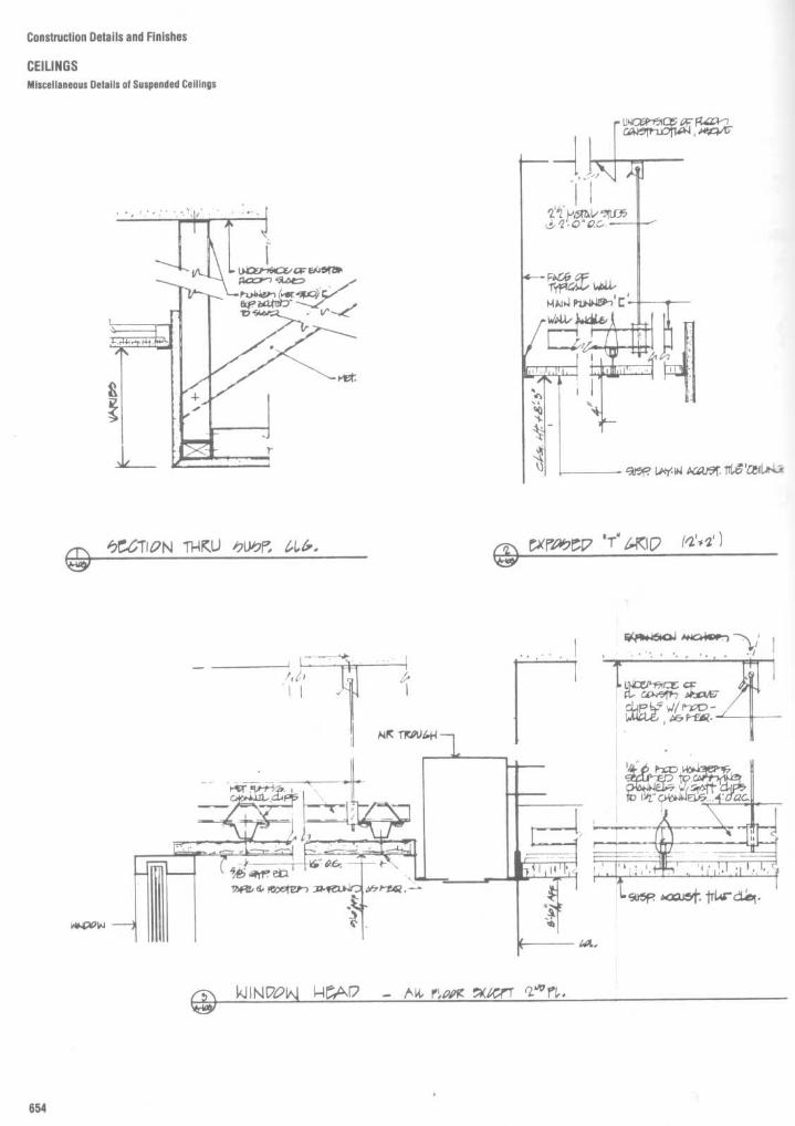
Construction Details and Finishes
CEILINGSMiscellaneous Details of Suspended Ceilings

Construction Details and Finishes
CEILINGSMiscellaneous Details of Suspended Ceilings

Construction Details and Finishes
CEILINGSSuspended Cellings : Perimeters and Drops

Construction Details and Finishes
CEILINGSGypsum Board and Plaster Suspended Ceilings

Construction Details and Finishes
CEILINGSSuspended Ceilings

Construction Details and Finishes
CEILINGSReflected Ceiling Plan

Construction Details and Finishes
STAIRS
Planning Data
Nowhere is the personal safety and com-fort of the user more important than. i n thedesign of stairs . This section, therefore,provides the planning data necessary tosolve most problems of stair design . Variousstair types are illustrated, including straightrun, long "L ;' wide "L ;' double "L ;' andnarrow and wide "U :' Stair tables and relateddiagrams are provided that indicate verticaland horizontal areas, headroom clearances,and tread and riser dimensions for variousstair systems. Information concerning nos-ings, landing widths, etc ., is also included . Inaddition to general planning data, this sectionincludes barrier-free design data as well asactual construction details of wood, steel,and concrete stairs prepared by various de-sign firms.
It should be noted that stair design mustconform to local building codes. Most codesrequire that means-of-egress stairways notbe less than 44 in (1118 mm) in width, that theleast dimension of landings and platformsnot be less than the required width of thestair, and that the minimum headroom in allparts of a stairway not be less than 6 ft 8 in(2032 mm) measured vertically from thetread nosing or from the floor surface of the
landing or platform . In one- and two-familydwellings, most codes require that stair-ways not be less than 3 ft (915 mm) clear inwidth, and that hand rails not be less than30 in (762 mm)nor more than 34 in (864 mm)measured vertically from the nosing of thetreads and be provided on at least one side ofstairways of four or more risers .
CRITICAL DIMENSIONS ANDCLEARANCES
Stair Table
Dimensions indicated in Fig. 1 and listed inTable 1 determine the vertical and horizontalareas and headroom clearances for stairsystems with tread and riser proportionsshown . They can be used directly in develop-ing sketches or working drawings and elimi-nate the need for experimental stair plans orsections . All dimensions refer to face oftreads without nosing .
Tabular data refer only to minimum condi-tions for straight run stairs . All figures maybeadjusted according to requirements of de-sign or stair use. For similar dimensionalinformation controlling other types of stair-ways, see the following pages.
Widths of stairways may vatrequirements . For passage of fu~rneua"tmum clear widths should be sea.^a7dTable 2.

Construction Details and Finishes
STAIRS
Planning Data
3earances for Furniture Passage
Awth is not always a critical factor of stair-mev design but is important when the layoutmovesone ormore turns with straight runs .%oical layouts for such stairways include theJng L, Double L, Wide U, Wide L, and%&row U. (See Fig. 3 for layouts and tabularZra on these types .)Stairways used solely as circulation from
ioo(to floor can be 2'0"wide for comfortablepassage of one individual or 3'6" for two,soe-by-side . When furniture must be takenAc and down, minimum clear widths ofszr&ght runs and landings must be carefullysemected or corners will constitute obstruc-acrs in many instances.recommended minimum clear widths as
shown in Table 2 are not necessarily thewidth of stairs, either rough or wall-to-wall .erections of newels, handrails, or base-3cards can obstruct passage of furniture and-i_st be taken into account when determin-rc actual stair widths .Headroom is also a controlling factor of
Zes+gn . With minimum headroom conditionssnown in Table 1, clear widths for furniturepassage must be greater in most cases thann-ay be necessary if headroom is unlimited or®oial at least to the ceiling heights. This is::arucularly important at the first riser and at*urns, where the under rake of the first stairir-its the vertical clearance of the stairway:reow. Therefore, if stairs must be com-:;aratively narrow and if furniture must besansported over them, headroom, or verticalaearance, must be increased accordingly.Landing widths may be increased to pro-
woe greater turning space for maneuvering'i If this is done, minimum clearw,Cths can be proportionately decreased.-cwever, this expedient is not effective~uniess hallways at either end of the stairwayare at least equal to the landing widths .grow hallways often offer as great an:Dstruction to furniture maneuvering as lowHeadroom, narrow runs, or cramped turns .Open-well stairways give more oppor-
7.roty to maneuver furniture, since even veryv but light pieces may often be lifted over
-ais or newels . In general, a closed-stringstar should be wider than an open-stringlave for the same degree of convenience.
-,e data in Table 2 reflect safe averageearances for transportation of items listed .
Dimensions of furniture are subject to widearations . Consequently, the minimum clearagdths recommended here are susceptiblezadjustment in certain instances.
rvr
Fig . 2
Minimum stairwidths . (a)Stairs designed forcomfortable human passage only maybe relatively narrow . W, may be 2'0" but 2'6" is better. Wz should be at least 3'6" .(b)Furniture passage demands greater width. If stair landing is increased or headroomunlimited, WF may be decreased . See Table 2.

Construction Details and Finishes
STAIRS
Planning Data
Purpose
The six diagrams in Fig. 3 represent unit plansfor types of nonwinder stairways which aremost frequently encountered in the averageresidential planning problem . Tabular infor-mation with each was developed from datacontained in Table 1 .
Unit plans are drawn to '/d" scale andtherefore can be supplied directly as a checkof stair layouts to sketch plans and eleva-tions. Each represents an average conditionwith a stair pitch well within the comfortzone . The basis is a 9'6" floor-to-floor heightwith 16 risers each 7.13" in height . Width is3'0" from wall to wall .
Tabular data with each unit plan indicatedimensional variations which occur whenstairways of substantially similar pitchesare planned for floor-to-floor heights from8 to 11 ft .
Width is the only critical dimension miss-ing from this unit plan information . This varieswith requirements of design and stair useand should be selected from data in Table 2.Width is a dimension controlling critical clear-ances on all stairs that contain a turn .Winders have not been included in these
unit plans because they represent a staircondition generally regarded as undesirable .However, use of winders is sometimes nec-essary due to cramped space. In such in-stances, winders should be adjusted to re-place landings so that the narrow portions oftreads at the inside of the turn are at leastequal to 3/4" T When this is done, dimensionsof L, and Ll are decreased by approximately'/2T, the exact figure depending upon thewidth selected . The practice of adding awinder-riser to bisect the landing diagonallyfrom the corner of a newel is to be avoided in
all cases for it produces a dangerousf mrow step in a particularly undesirable Dan
Application of Unit Plans
Diagrammatic data can be used on s " =r.as a graphic check as noted. Tabular ca -_ zwbe applied to either sketches ordrawings to eliminate the necessity o= otw-oping experimental stairway sections tJWtermine run, proportional rise, horizonta arevertical areas, and location of unde"areminimum headroom .
Dimensional data have been confineo11cuarsingle pitch for all floor-to-floor heights 7*pitch indicated is that most generally 3arable for human comfort. Data forpitches listed as tread and riser propcr-:4CREin Table 1 can be substituted for values ar _ .
Lz , and M .
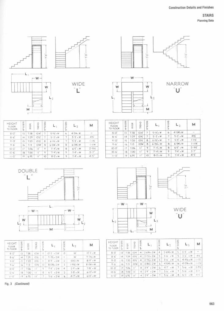
Construction Details and Finishes
STAIRSPlanning Data

Nosings
Nosings extending 3/4 to 1112 in (usually 1'/4 in)beyond the face of the riser are functionallynecessary and are required by most buildingcodes. Nosings may be provided by extend-ing the treads or by sloping the risers . Thelatter method is customary in concrete stairsbecause of easier forming, and in any type ofstair where carpet is to be installed . This typeof nosing is also recommended for stairs tobe used by the handicapped.
Stairway Layouts
Comfortable stairways cannot be designedexcept in relation to dimensions of the aver-age human figure . As applied to stairwaysthese dimensions and the equivalent of theaverage comfortable walking stride of about24 in fix the gradient of stairways, the pro-portional relation of treads and risers, theheight of the handrail, and the minimumnecessary headroom .
Figure 4 indicates the influence of humanfigure dimensions and suggests the desir-ability of varying ceiling clearances and hand-rail heights according to variations in stairgradients. These variations are included inTable 3.
Treads and risers in curved stairs should beproportioned on an assumed "line of travel"18 in from the inner (smaller radius) handrail .
All building codes have strict specificationsfor stairs which are required exits. The Na-tional Building Code of the American Insur-ance Association and the NewYork City codeboth require that treads and risers be propor-tioned by the formula T x R = 70 to 75, withrisers notover 73/4 in high and treads not lessthan 9 in wide, exclusive of nosings . Mini-mum stair width for most uses is 44 in, basedon two 22-in lanes of traffic . Handrails arerequired on both sides and may project amaximum of 3'/2 in into the required width .Winders and open risers are prohibited . Themaximum vertical rise permitted betweenlandings is 12 ft ; in places of assembly it is8 ft . Stairs must be designed for a live loadof 100 Ib/ft2 .
Construction Details and Finishes
STAIRS
Lavouts and Dimensions

Construction Details and Finishes
STAIRSWood Stairs

Construction Details and Finishes
STAIRSWood Stairs

Construction Details and Finishes
STAIRSMiscellaieous Stair Details

Construchou Details and Finishes
STAIRS
Miscellaneous Stair Details

Construction Details and Finishes
STAIRS
Miscellaneous Stair Details
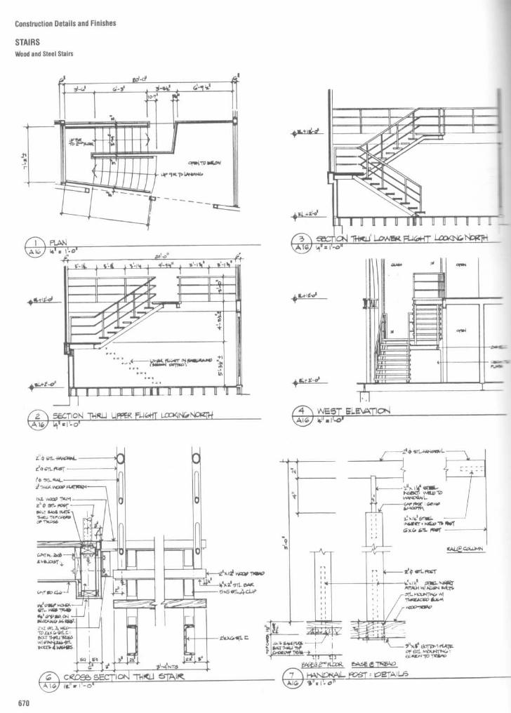
Construction Details and Finishes
STAIRSWood and Steel Stairs

Construction Details and Finishes
STAIRSWood and Steel Stairs

Construction Details and Finishes
STAIRSConcrete Stairs

Construction Details and Finishes
STAIRSWood Handrail Components
A-DE-GH-I
KL\tN
O-RS
TU`r
W
X
Starting Newels
Landing Newel
Starting StepStair TreadLanding TreadRisersReturn NosingStair Cove
Turned BalustersWall RosettePlain CapOne OPG Newel CapTandem CapQuarter Turn CapQuarter TurnUp Easing
AAABB
CCDDEEFF
GG
HH
JJhh
Overhand Easing90 degree Up EasingVoluteTurnoutGooseneck 2 RiserGooseneck 1 RiserGooseneck 1 RiserLedge ReturnGooseneck Riserwith Cap
Gooseneck RiserTandem CapStartinv Easing
Starting h.asing withR1 .411111 Eiid
Band Rail

Construction Details and Finishes
STAIRSSpiral and Circular Stairs

Construction Details and Finishes
STAIRS
Circular/Oval Stairs

Construction Details and Finishes
STAIRSSpiral Stairs

1I"es of Stairs- : .r -ypes of stairs are defined: straightr-ai - 5 circular stairs, curved stairs, and spiralfir_Taight stairs are by far the most common
representing the bulk of the stair mar-Though the term "straight" is self-
eiDanatory, for purposes of classification asoakgnt stair is defined as one in which thesirrgers are straight members. Straightears, unlike stairs of the other three types,nra. tie arranged in several different ways :
Straight run: Either a single flight ex-irong between floors, as shown in Fig. 5A,
a series of two or more flights in the samewe with intermediate platforms betweenr. as shown in Fig. 5B .
rârallel : Successive flights which paral-aeach other and are separated only by one:ramore intermediate platforms, as shown in
°;4 5C.Angled: Successive flights placed at an
wgre of other than 180° to each other (often3C" with an intermediate platform betweenma-, as shown in Fig. 5D or E. The typeY-cwn in Fig. 5D is often referred to as a"*rlssed" stair.
Scissor: A pair of straight run flightszwaileling each other in plan and running in>taoosite directions on opposite sides of awioing wall, as shown in Fig. 5FC rcular stairs are stairs which, in plan view,
ra.e an open circular form, with a singlemrter of curvature . They may or may notoweintermediate platforms between floors .
Cirved stairs are stairs which, in plan view,lw.e two or more centers of curvature, beingara . elliptical, or some other compoundnrrved form . They also mayor may not haveoneor more intermediate platforms between'%Dors.
Spiral stairs are stairs with a closed circularporn, having uniform sector shaped treadsand a supporting center column .
Muses of Stairs
`-e class designation of stairs, as already-cred, is a keyto the type of construction, the3-a qty of materials, details and finish and, in-cut cases, the relative cost . As stairs of all-asses are built to meet the same standards
performance in respect to load carryingzapacity and safety, these class distinctions3o not represent differences in functional.clue, but in character and appearance . It isrrportant to recognize that where function isre prime concern, and esthetics are of minorrnportance, significant economies can bexnieved by specifying one ofthe less expen-sNe classes.The following four classes of stairs are
isted in order of increasing cost (as a general-u,e) ; the general construction charac-"-enstics of each class are described .
Industrial class. Stairs of this class arepurely functional in character and conse-puently they are generally the most econom-cal. They are designed for either interior orexterior use, in industrial buildings such as~actories and warehouses, or as fire escapesor emergency exitways . They do not includestars which are integral parts of industrialequipment.
Industrial class stairs are similar in natureto any light steel construction . Hex head
bolts are used for most connections, andwelds, where used, are not ground . Stringersmay be either flat plate or open channels ;treads and platforms are usually made ofgrating or formed of floor plate, and risers areusually open, though in some cases filled pantype treads and steel risers may be used .Railings are usually of either pipe, tubing, orlight steel angle construction .
Service class. This class of stairs serveschiefly functional purposes, but is not unat-tractive in appearance . Service stairs areusually located in enclosed stairwells andprovide a secondary or emergencymeans oftravel between floors . In multistoried build-ings they are commonly used as egressstairs . They may serve employees, tenants,or the public, and are generally used whereeconomy is a consideration.
Stringers of service stairs are generally thesame types as those used on stairs of theindustrial class . Treads maybe one of severalstandard types, either filled or formed of flooror tread plate, and risers are either exposedsteel or open construction . Railings are typ-ically of pipe construction or a simple bar typewith tubular newels, and soffits are usuallyleft exposed . Connections on the undersideof the stairs are made with hex head bolts,and only those welds in the travel area aresmooth .
Commercial class. Stairs of this class areusually for public use and are of more attrac-tive design than those of the service class .They maybe placed in open locations or maybe located in closed stairwells or in public,institutional, or commercial buildings .
Stringers for this class of stairs are usuallyexposed open channel or plate sections .Treads may be any of a number of standardtypes, and risers are usually exposed steel.Railings vary from ornamental bar or tubeconstruction with metal handrails to simplepipe construction, and soffits may or maynotbe covered. Exposed bolted connections inareas where appearance is critical are madewith countersunk flat or oval head bolts;otherwise, hex head bolts are used . Welds inconspicuous locations are smooth, and alljoints are closely fitted .
Architectural class. This classification ap-plies to any of the more elaborate and usuallymore expensive stairs, those which are de-signed to be architectural features in a build-ing . They may be wholly custom designed ormay represent a combination of standardparts with specially designed elements suchas stringers, railings, treads, or platforms .Usually this class of stair has a comparativelylow pitch, with relatively low risers andcorrespondingly wider treads . Architecturalmetal stairs may be located either in the openor in enclosed stairwells in public, institu-tional, commercial, or monumental buildings.The materials, fabrication details, and
finishes used in architectural class stairs varywidely, as dictated by the architect's designand specifications . As a general rule, con-struction joints are made as inconspicuous aspossible, exposed welds are smooth, andsoffits are covered with some surfacingmaterial . Stringers may be special sectionsexposed, or may be structural membersenclosed in other materials. Railings are of arornamental type and, like the treads ancrisers, may be of any construction desired .
Construction Details and Finishes
STAIRS
Classification of Steel stairs
General Requirements, All Classesof Stairs
All fixed metal stairs, regardless of class, areof fire-resistant construction and are de-signed and constructed to carry a minimumlive load of 100 pounds per square foot ofprojected plan area or an alternative concen-trated load of 300 pounds applied at thecenter of any tread span . Railings and hand-rails are designed and constructed to with-stand a minimum force of 200 pounds ap-plied in any direction at any point on the rail .

Construction Details and Finishes
STAIRSGeneral Purpose Steel Stairs

Construction Details and Finishes
STAIRSSteel Stairs

Construction Details and Finishes
STAIRSSteel Stairs

Construction Details and Finishes
STAIRSSteel Stairs

Construction Details and Finishes
STAIRSSteel Stairs

Construction Details and Finishes
STAIRS
Stair Platform Construction
-e platform (Fig . 6) is shown constructed.,, r- a steel channel, A, of adequate strengthin span the well on line X, through Secs . 1, 2,wc 3. and supported at both ends by the wallw-rigs . Newel posts rest on this channel-rrough angle clips, around which the plat-r_r--t plate is cut (Sec . 3) . Face strings havewaded end plates with flathead screws"acoed into the newels (Sec . 2) .--e two platforms with two intermediate
- s (Fig . 7) are shown constructed with thecad carried on line Yby string B, post C, andxannel D, which are shown bolted togetherSecs . 8, 9, and 10) with through bolts. Thecad is also carried from post C on line Z in thesame manner.The members at post C may be brought
IDgether and welded and the post fitted over,:^e connection, or the entire unit welded .
Stairs are supported by one or more of the following methods, (a) String at floor rests direct-ly on floor construction ; (b) String at landing or platform extends into adjacent load-bearing wall ;or (c) String of landing or platform is supported by struts extending to the floor below, thesebeing of angles, I-beams or pipes either set in the wall or exposed; or (d) String at landing orplatform is supported by rods hung from the floor above, either set in walls or exposed ; (e)String paralleling load-bearing wall may have shelf brackets on the back of the strings and setin wall ; similar brackets may be used with struts or hanger rods .
CONDITIONS ILLUSTRATED:Concrete or terrazo fill.Open unplastered soffit.Square steel newel posts.Steel Channel Strings.

Construction Details and Finishes
STAIRS
Stairwell

Construction Details and Finishes
STAIRSStair Width Dimensions

REFER TO GOVERNING CODES TO ESTABLISH DIMENSIONS
Height of riser and tread run vary according to governing codes . A treadof 10" and a rise of 7" to 7 1/2 " are considered average . Stair treads formore comfortable runs are often 10112 " to 11 " with risers less than 7" .Treads and risers should be so proportioned that the sum of two risersand one tread run is not less than 24" or more than 26" .In establishing stair well dimensions, tread run is always face to face ofriser .
Construction Details and Finishes
STAIRSStair Length Dimensions
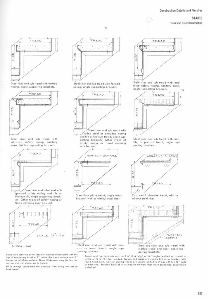
Construction Details and Finishes
STAIRS
Tread and Riser Construction

Construction Details and Finishes
STAIRSTread Sections
1

Construction Details and Finishes
STAIRSString Sections

Construction Details and Finishes
STAIRSStringer Sections

Construction Details and Finishes
STAIRS
Abrasive Nosings and Treads

Construction Details and Finishes
STAIRSHandrails

Construction Details and Finishes
STAIRSNewels and Railings

Construction Details and Finishes
STAIRSNewels and Railings

Construction Details and Finishes
STAIRSOrnamental Railings
Figures 9 and 10 indicate typical railings fornecks, platforms, balconies, roofs, and sim-oar locations, adapted for residential, apart-ment, or hotel construction . These railingsmay be fastened with wood screws or lagDolts to wood, or with expansion bolts tomasonry. On roofs or decks the setting of thecost bases should be waterproofed .

Construction Details and Finishes
STAIRS
Ornamental Railings

Construction Details and Finishes
STAIRSCenter Railings
Center railings are recommended for widestairs . They may be a single pipe or tubingrailing or they may be designed with doublerails and panels of interesting design .
Note : A number of codes require thatrailings have a level extension beyond thenosings at the floors as indicated in Fig . 11 bydashed lines . This applies to both wall andcenter railings .

Construction Details and Finishes
STAIRSRailings

Construction Details and Finishes
STAIRSRailing Posts

Construction Details and Finishes
STAIRS
Handrail Sections
TYPICAL EXTRUDED ALUMINUM AND BRONZE HANDRAIL SECTIONS

REPRESENTATIVE EXTRUDED ANDTUBULAR STAINLESS STEEL HANDRAIL SECTIONS
Construction Details and Finishes
STAIRS
Handrail Sections
General Information
Functional and decorative plastic handrailmouldings of polyvinyl chloride plastics areavailable in a variety of sizes and profiles,several of which are illustrated in Figs . 16 to19 . Consult suppliers' current literature forvariations in details and features .
Plastic handrail mouldings are not struc-tural and require bar, tube, or channel mem-bers to support vertical and horizontal loads .
Plastic handrail mouldings are produced ina range of colors from subdued to bright, tosuit either formal or informal design situa-tions. The color is integral with the plastic
which is highly resistant to wear, weathering,and corrosion.The thermoplastic material becomes plia-
ble when heated (not over 166°F), at whichtime it can be fitted over the support memberand conforms to vertical, horizontal, or com-bined vertical and horizontal curves withincertain limitations .
Lateral bends should have a minimumcenterline radius of not less than 2 times thewidth of the plastic section or 21/2 to 3 timesthe width of the support section, whicheveris greater. Mitered corners should be used if
sharper turns are required .Combined vertical and horizontal turns can
be formed by twisting the moulding .The material can be joined by thermal
welding, and end caps can be shaped using aknife, a file, or abrasives.The use of a cleaning solution for removing
grease and foreign material is recom-mended, after which a solvent is used forpolishing or removing abrasive scratches .Normal cleaning requires only soap andwater.

Construction Details and Finishes
STAIRSWall Handrail Brackets
Walt rail bracket of conventional cast design, malleable iron,aluminum or bronze . 318" bolt into wall .
Wall rail bracket of extruded aluminum,made to set at right angle to wall rail or setvertically . 318" bolt into wall .
Wall rail bracket of conventional cast design, malleable iron,aluminum or bronze, 3l8" stud into wall, tapped into arm ofbracket
Two-piece wall rait bracket of aluminum . Wall plate bolted in-to wall through expansion type anchor . Outer sleeve screwedto rail . Outer sleeve fastened to wall plate by set screw .
Wall rail bracket of aluminumwith fittings to handrail adjust-able to any pitch . 3l8" stud intowall .
Wall rail bracket of formed steel . Filler and anchorbolt through gypsum board on masonry. Bracket fas-tened to filter by three screws or by 318" bolt throughcenter .
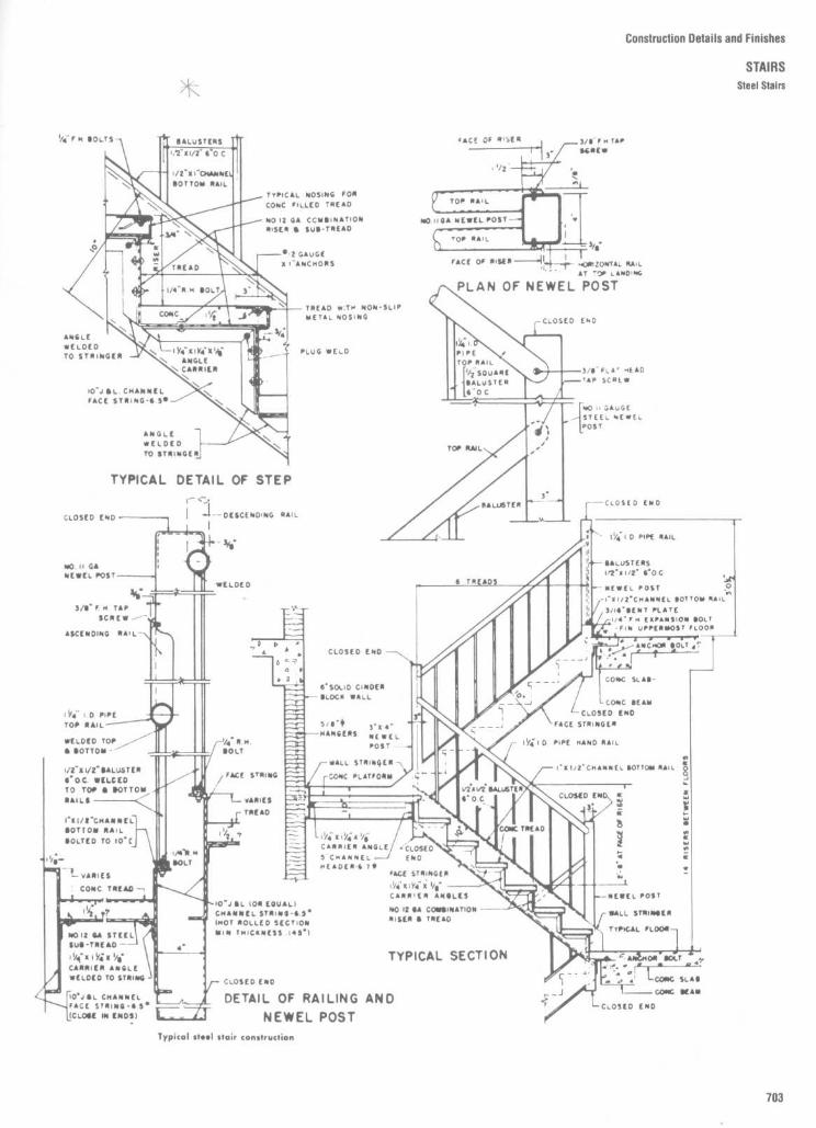
Construction Details and Finishes
STAIRSSteel Stairs

Construction Details and Finishes
STAIRSSteel Stairs

Construction Details and Finishes
STAIRSSteel Stairs

Construction Details and Finishes
STAIRSSteel Stairs
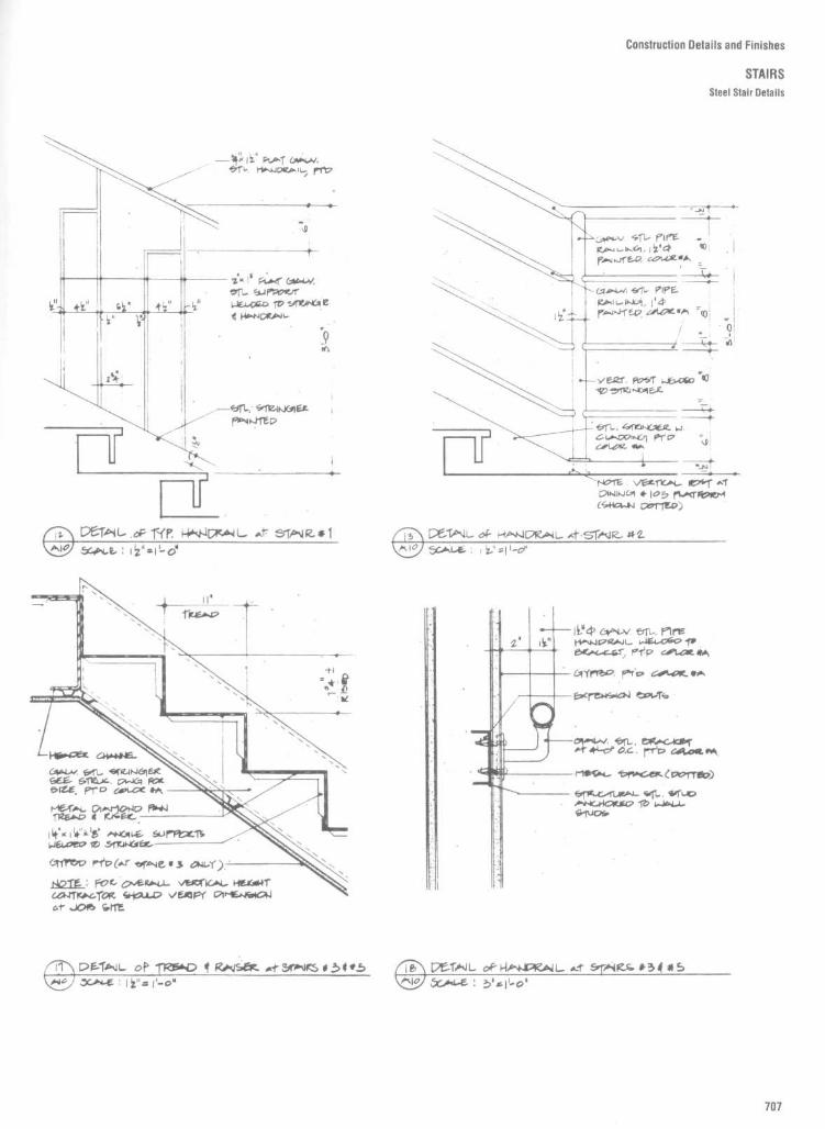
Construction Details and Finishes
STAIRSSteel Stair Details

Construction Details and Finishes
STAIRSSteel Stairs
STEEL STAIRS WITH TERRAZZO TREADS

Construction Details and Finishes
STAIRS
Spiral Stairs
Construction
Material may be steel, stainless steel, castiron, or aluminum . Treads are supported incantilever fashion by the column, each con-secutive tread being rotated at a predeter-mined angle. The platform attaches to thecolumn and is fastened to the floor structureto hold the column secure . The spiral railing issupported by balusters attached to the outerends of the treads .
Tread Designs
Fabricators provide several standard typesand designs of treads and platforms . Theseinclude open riser, closed riser, and cantilevertypes, with surface of checkered plate, abra-sive plate, steel grating, or plain surface toreceive wood, resilient flooring, carpet, orother covering . Pan type treads to receiveconcrete or terrazzo fill are also available
Stair Height
Spiral stairs are adaptable to any height, theheignt being equal to the distance fromfinished floor to finished floor.
Stair Diameter
Spiral stairs are available in various diametersfrom 3'6" to 8'0", normally in 6" increments . A4'0" diameter is considered minimum forgeneral access purposes ; a 5'0" diameterprovides a comfortable general purpose stair.Larger diameters are used chiefly for archi-tectural effect . Note that the diameter of thefinished well opening should be at least 2"greater than the stair diameter, to providehand clearance
Hand of Stairs
Left-hand stairs : User ascends in clock-wise direction, with handrail at left .
Right-hand stairs : User ascends incounterclockwise direction, with handrail atright.

Diameter and headroom
Spiral stairs maybemade in diameters from 3'6" to 6'0" o"greater, with 4'0" usually considered theminimum for easy travel . The well holeshould be at least 3" larger in diameter thanthe stair, for railing clearance. Spiral stairs areusually constructed with 12 or 16 treads tothe circle . Head room should be calculated orthe basis of three-fourths of a circle . On a 12-tread circle, 9" is approximately the minimurrrise, providing 6'9" head room . On a 16-treatcircle, 7" rise will provide 7'0" head room .Ariseupto12"pertreadmaybeemployed.
Construction Details and Finishes
STAIRS
Spiral Stairs

Construction Details and Finishes
STAIRSCircular Stairs
Circular stairs placed between watts may be built self-sup-porting at the inner string and be supported by concealedstruts or hangers at the outer string . When completely exposeda circular stair may be designed to require few supportsbetween floors .In constructing a circular stair the overall size of the well andthe tread length of the stairs may be adjusted to fit the par-ticular conditions of the structure . Treads should be a minimumwidth of 8" at a distance 15" out from the inside railing . Thetreads may be of steel, abrasive cast iron, abrasive non-ferrous metal, cement, tile, linoleum, wood, marble or othermaterial .
Landings and platforms may be constructed as part of the stair, and maybe supported by beam or cantilever construction . Wall rails and bracketsmay be constructed with handrail sections matching the railing.Face strings and railings may be similar to those used on straight stairs butshould be designed of shapes adaptable to abrupt curved construction .The small radius to which these are constructed offers possibilities ofdesign that should not be overlooked . Combinations of contrasting metalcolors can be effectively employed in such installations .

Construction Details and Finishes
STAIRSConcrete Stairs

Construction Details and Finishes
STAIRSConcrete Stairs

Construction Details and Finishes
STAIRS
Concrete, Steel, and Terrazzo Stairs

Construction Details and Finishes
STAIRSMarble Treads

Construction Details and Finishes
STAIRS
Slate Treads

Construction Details and Finishes
STAIRS
Planning Data
Any potential hazards must be eliminated .Stairs should be "easy going," that is, theremust be an appropriate relationship of riser totread. Treads are of nonslip material which isalso extended onto platforms and landingsfor a distance equal to the width of the stairtreads . Double handrails, one higher than theother, are provided on stairs for each line ofshort or tall pupils . The posts, which supportthe center handrails of double stairs, areextended high enough above the top handrailto prevent pupils from sliding down .

Construction Details and Finishes
STAIRSBarrier-Free Design Data
NOTEX is the 12 to minimum handrail extension required
at each top rlserY Ls the minimum handrail extension of 12 in plus thewidth ofone tread that is required at each bottom riser.

Construction Details and Finishes
STAIRS
Barrier-Free Design Data
Steps and Stairs
Steps and stairs should have nonprotrudingnosings so that people with stiff joints,braces, artificial legs, or other leg or stabilityproblems will not catch their toes as theyclimb.
Handrails should be oval or round with1Yz"/4 cm hand clearance between the railsand the wall : 1 112"14 cm clearance will provideease of grip but will prevent the hand or wristfrom slipping between the handrail and thewall if the person loses balance. Handrailsshould be positioned on both sides of stepsand stairs and should extend beyond the firstand last steps on at least one side andpreferably on both to allow people with longleg braces to pull themselves beyond thesepoints . To guard against falls and to helpchildren, some codes require another, lowerhandrail .Steps, stairs, and handrails should not be
made of slippery material .

Construction Details and Finishes
STAIRSLadders

Construction Details and Finishes
STAIRS
Ladders ; Open Steel Stairs

ConstructionDetailsandFinishes
STAIRS
Steel Pan Cement-Filled Stairs

Now and rise Provide the least practical. . ._a for any ramp or curb ramp subject
--e following new constructionac . cements :
T Maximum running slope shall not ex-m+ed 1 :12 (8 .3%)2. Maximum rise for any run shall not
exceed 2'6" (760 mm)
Width
Ramps and curb ramps shall have aminimum clear width of 3'0" (915 mm) ex-clusive of edge protection or flared sides.Cross-slope and surface
Cross-slope of rampsurfaces shall not exceed 1 :48 (Y4 in/ft).
Construction Details and Finishes
STAIRS
Barrier-Free Ramps

Construction Details and Finishes
FIREPLACES
The function of the fireplace today differsdramatically from its role of years ago .Whereas its original function was primarily toprovide heat for warmth and/or cooking,today it serves more as a decorative assetand as the focal point of interior spaces andconversational groupings, providing the es-thetic pleasure and comfort of firelight.
Of particular interest to the interior de-signer is the proportion and scale of thefireplace opening, the treatment of wall sur-faces surrounding the fireplace, the design ofmantel pieces and hearth extensions, andthe array of fireplace accessories available .Accordingly, the information contained in thissection addresses these considerations .Drawings include elevations, plans, and de-tails of various fireplaces ; elevations of awide selection of prefabricated manteltypes ; and a sampling of fireplace accesso-ries including andirons, wrought iron firesets, and log grates . It should be noted that,aside from their decorative aspects, thefireplace and chimney have important struc-tural implications and require special founda-tions . Moreover, the fireplace must be de-signed to carry smoke away safely.With respect to hearth extensions, most
building codes require that for fireplaceshaving an opening of less than 6 ft' (0 .56 m2 ),the hearth must extend a minimum of 16 in(406 mm) beyond the face of the opening anda minimum of 8 in (203 mm) on each side . Forfireplaces whose openings exceed 6 ft 2, thehearth must extend a minimum of 20 in (508mm) beyond the face of the opening and 12 in(305 mm) on each side .
Most building codes also require thatwoodwork or other combustible materialsnot be placed within 6 in (153 mm) of afireplace opening, and that combustible ma-terial within 12 in (305 mm) of a fireplace
opening not project more than %a in for each1-in distance from such an opening .
Since building codes may vary, it is impor-tant that the designer have her or his planschecked for conformance with the applicablelocal or state codes . Any structural modifica-tions to an existing fireplace and chimney orthe design of a new fireplace and chimneyshould be reviewed by a professionalengineer or registered architect .A fireplace that draws properly can be
assured by applying proper principles ofdesign . The size of flue should be adequateand should be based upon the size of thefireplace opening . One rule commonly usedis to take one-tenth of the area of thefireplace opening to find the minimum area ofthe flue . For example, if a fireplace had anopening 3 ft wide by 2 ft 6 in high, it wouldhave an area of 1080 in', One-tenth of 1080in 2 equals 108 in2 . The standard-size fluenearest to this requirement and readily avail-able is a 13- by 13-in flue lining, which has aninside cross-sectional area of 126.56 in' . Onecould also use a 13-in round flue that has across-sectional area of 113 .0 in' .The front of the fireplace should be wider
than the back and the upper part of the backshould tilt forward to meet the throat in orderto throw heat into the room instead of up thechimney. The arch over the top of the fire-place opening should be only 4 in thick, andthe throat should project toward the front asmuch as possible to form the smoke shelfbehind it . The area of the throat should be 11/4times the area of the flue, with minimum andmaximum width of 3 and 41/2 in, respectively,so that the narrow throat will cause a quicksuction into the flue . The sides of the fire-place above the throat are drawn together toform the flue, which always starts exactlyover the center of the width of the fireplace .
The smoke shelf is very necessary to stccback drafts . The depth of the fireplace shou I_be one-half the height of the opening, with z-maximum of 24 in . The back should rise
onehalf the heightofthe openingbefore slopircforward and should be two-thirds the opening in width.
The back, sides, and parts of the heartthat are under the fire must be built of
hearesistant materials . Firebrick laidinfire clayrsthe best combination .The damper is a large valve that can be
adjusted to regulate the draft . Many types c=commercial damper units are manufacturesThe position of a damper unit is
importantThe damper is generally set about 8 in abovethe top of the fireplace opening and isconcealed by the brickwork . One advantageof these units is that they are correct,,designed and have correctly proportionecthroatdamper and chamber to provide a formfor the masonry and to reduce the risk offailure in the function of the completesfireplace .The hearth consists of two parts, the front
or finish hearth and the back hearth underthefire . The front hearth is simply a precautionagainst flying sparks and, while it must benoncombustible, it need not resist intenseprolonged heat . Because the back hearthmust withstand intense heat, it is built ofheat-resistant materials . In buildings withwood floors, the hearth in front of the fire-place should be supported on masonry Thefront hearth should project at least 16 in fromthe front of the fireplace .At the back part of the hearth it is custom-
ary to have an ash dump for dropping theashes into the ash pit, which is generallylocated in the basement with a door forcleaning out ashes .

Construction Details and Finishes
FIREPLACES
Components and Terminology

Construction Details and Finishes
FIREPLACES

Construction Details and Finishes
FIREPLACESDesign Data

Construction Details and Finishes
FIREPLACESThrough or Two-Way

Construction Details and Finishes
FIREPLACESCorner Design

Construction Details and Finishes
FIREPLACES

Construction Details and Finishes
FIREPLACES

Construction Details and Finishes
FIREPLACES

Construction Details and Finishes
FIREPLACESMarble Mantels
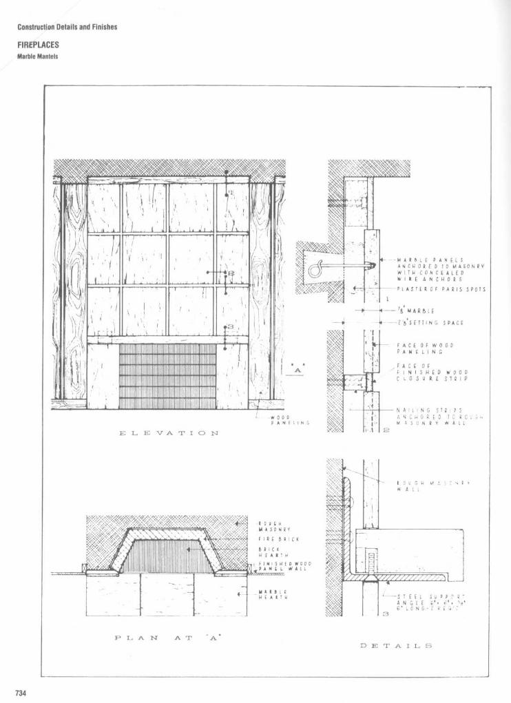
Construction Details and Finishes
FIREPLACESMarble Mantels

Construction Details and Finishes
FIREPLACESMarble Mantels
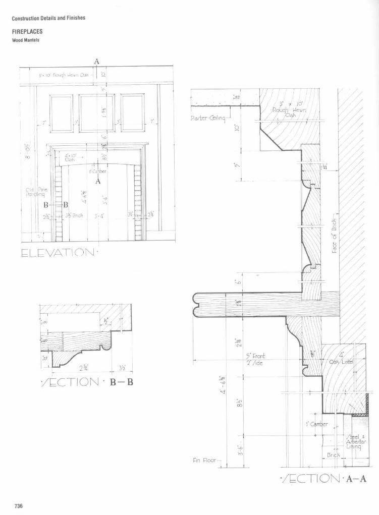
Construction Details and Finishes
FIREPLACESWood Mantels

Construction Details and Finishes
FIREPLACESWood Mantels

Construction Details and Finishes
FIREPLACESWood Mantels

Construction Details and Finishes
FIREPLACES
Wood Mantels

Construction Details and Finishes
FIREPLACESWood Mantels

Construction Details and FinIshes
FIREPLACESWood Mantels

Construction Details and Finishes
FIREPLACES
Fireplace Accessories
Fig . 7
Fireplaces offer opportunities for the use and display of a variety of metal items of decorative value. These may be selected ordesigned to match other material in the room . Metals used for wrought and cast fireplace products are usually cast iron, steel in a darkhammered finish, or polished brass. Combinations of these metals and other metals may be used very effectively.

Construction Details and Finishes
LIGHTINGPlanning Data : Minimum Shade Heights
Although lighting design is a discipline inand of itself, the interior designer and archi-tect must be knowledgeable about the inter-face between lighting elements and theinterior architecture . This section, therefore,focuses primarily on the detailing of thisinterface . Details from actual contract draw-ings, prepared by various interior design andarchitectural firms, are provided for thereader's reference. Among the details arethose for valence and cove lighting and forthe lighting of stairs, columns, and skylights .This section also provides some basic plan-ning data including illuminance values forresidences, offices, stores, and industrialspaces .

Construction Details and Finishes
LIGHTINGPlanning Data : Minimum Shade Heights

Construction Details and Finishes
LIGHTINGFloor Lamps

Construction Details and Finishes
LIGHTINGTable Lamps

Construction Details and Finishes
LIGHTINGDesk Lamps

Construction Details and Finishes
LIGHTING
Wall-Mounted Task Lamps

Construction Details and Finishes
LIGHTING
Planning Data: Residential Valance Lighting

TABLE 1
Illuminance Values for Residences`
Illuminance
Foot-Specific visual tasks
candles
Luxt
Dining
15 150Grooming, shaving, makeup
50
500Handcraft
Ordinary seeing tasks
70
700Difficult seeing tasks
100
1000Very difficult seeing tasks
150
1500Critical seeing tasks
200
2000Ironing (hand and machine)
50
500Kitchen duties
Food preparation andcleaning
150 1500Serving and other
noncritical tasks
50
500Laundry
Preparation, sorting,inspection
50 500Tub area-soaking, tinting
50
500Washer and dryer areas
30
300Reading and writing
Handwriting, reproductions,and poor copies
70
700Books, magazines, newspapers
30
300Reading piano or organ scoresAdvanced (substandard size)
150
1500Advanced
70 700Simple
30 300Sewing (hand and machine)Dark fabrics
200
2000Medium fabrics
100
1000Light fabrics
50
500Occasional-high contrast
30
300Study
70 700Table games
30
300General lighting
Conversation, relaxation,entertainment
10 100Passage areas, for safety
10
100Areas other than kitchen
involving visual tasks
30
300Kitchen
50 500
`Minimum on the task at all timesf Lux is an SI unit equal to 0 0929 footcandle
Fig.15
Basic relationship forthe design of luminous panels . IA light level of 60 is (600 Ix)is produced by seven rows of three 40-Wfluorescent tubes on 18-in (457 mm) centers . Lightdistribution and surface luminance are approximately uniform .)
Construction Details and Finishes
LIGHTING
Planning Data : Residential Down Lighting

Construction Details and Finishes
LIGHTINGCove Lighting Details

Construction Details and Finishes
LIGHTINGCove Lighting Details

Construction Details and Finishes
LIGHTINGCove Lighting Details

Construction Details and Finishes
LIGHTINGCove Lighting Details

Construction Details and Finishes
LIGHTINGCove Lighting Details

Construction Details and Finishes
LIGHTING
Fluorescent Cove Lighting Details

Construction Details and Finishes
LIGHTINGFluorescent Cove Lighting Details

Construction Details and Finishes
LIGHTING
Fluorescent Cove Lighting Details

Construction Details and Finishes
LIGHTINGCove Lighting for Merchandise Displays

Construction Details and Finishes
LIGHTINGMiscellaneous Lighting Details

Construction Details and Finishes
LIGHTING
Miscellaneous Lighting Details

Construction Details and Finishes
LIGHTINGMiscellaneous Lighting Details

Construction Details and Finishes
LIGHTINGMiscellaneous Lighting Details

Construction Details and Finishes
LIGHTINGMiscellaneous Lighting Details

Construction Details and Finishes
LIGHTINGHandrail Lighting Details
Elevation oflightedguardrail planterdemonstrates the useofcombined 3-foot and 4footfluorescent light strips toachieve overall lengths in ]-foot multiples. To minimize darkareas between lamps, use strips without end caps and installlamps back to back .
open circulation areas can be illuminated with lightedrailings, as shown in this section ofa lighted guardrailplanter.

Construction Details and Finishes
LIGHTING
StairLighting Photometrics

Construction Details and Finishes
LIGHTINGStair Lighting Details

Construction Details and Finishes
LIGHTINGStair Lighting Details

Construction Details and Finishes
LIGHTINGStair Lighting Details

Fig . 18
Skylight lighting . Skylight serves as fixture - does not interfere with natural lighting, will not cast shadows on luminous element . Spiral, M, U,
and straight lamps fabricated to fit curb opening .
Construction Details and Finishes
LIGHTING
Skylight Lighting Details

Construction Details and Finishes
LIGHTINGLighted Column Details

Cunslruction Details and Finishes
LIGHTINGLighted Column Details

Construction Details and Finishes
LIGHTINGLighted Column Details

Construction Details and Finishes
LIGHTING
Ceiling-Mounted Cold Cathode Lighting Details
Exposed/sculpture lamp lightingCold cathode lighting, an architectural
lighting tool with unusual flexibility.Lamps fabricated to the architectural
design, continuous line of light - low bright-ness -noglare -high efficiency-long life-approaches a permanent light source .
Remote transformers - no wiringtroughs, ballasts, ballast failures, or hum .Only 2 leads for up to 120 feet of lamps.
Excellent uniform dimming - no pre-mature flickering of individual lamps as withhot cathode lighting .

Construction Details and Finishes
LIGHTINGPlanning Data : Principal Lamp Types
Principal types of lamps for general lighting purposes
Type Maximum Average Characteristic features Typical application areaslamp lifeefficacy hrsIm/W
Normal 22 1,000 Easy to install, easy to General lighting in theincandescent use ; many different ver- home; decorative light-lamps and sions ; instant start ; low ing ; localized lighting ;reflector cost price ; reflector accent and decorativelamps lamps allow concen- lighting (reflector lamps)
trated light beams
Halogen 27 2,000 Compact, high tight out- Accent lighting,put, white tight ; easy to floodlightinginstall, tong life com-pared with normal incan-descent lamps
Tubular 104 20,000 Wide choice of tight cot- All kinds of commercialors ; high lighting levels and public buildings ;possible, economical in sireetlighting, homeuse lighting
SL * 61 10,000 Energy-effective ; direct Most applications wherereplacement for incan- incandescent lampsdescent lamps were used before
PL' 80 10,000 Compact, long life ; To create a pleasantenergy-effective atmosphere in social
areas, local lighting ;signs, security,orientation lightingand general lighting
Self-ballasted 28 12,000116,000 Long life, good color ren- Direct replacement fordering ; easy to install ; incandescent lamps ;better efficacy than small industrial and pub-incandescent lamps tic light projects ; plant
irradiation
High pressure 63 24,000+ High efficacy ; long life ; Residential area lighting,mercury reasonable color quality sports grounds; factory
lighting
Metal halide 94 15,000 Very high efficacy coin- Floodlighting, especiallybined with excellent for color TV, industrialcolor rendering ; long life lighting; road lighting;
plant irradiation
High pressure 125 24,000+ Very high efficacy ; Public lighting ; floodlight-sodium extremely long life ; good ing ; industrial lighting ;
color rendering plant irradiation EL :direct replacement formercury lamps
Low pressure 200 18,000 Extremely high efficacy ; Many different applica-sodium very long life; high visual tion areas wherever
acuity ; poor color render- energy/cost-effectivenessing : monochromatic tight is important and color is
not critical

A Bulb designation consistsof a letter(s) to indicate thesliape and a figures) toindicate the approximatemajor diameter in rights ofan inch . Bulbs are measuredthrough their grealesldiameter, in eights of aninch . Tluts, a F-15 bulb is aflame shape, 15 !ë of anindt or l'~ inches indiameter .
Construction Details and Finishes
LIGHTING
Planning Data : Incandescent Bulb Sizes
INCANDESCENT BULBS

Construction Details and Finishes
LIGHTING
Planning Data : Incandescent Base Types

Construction Details and Finishes
LIGHTINGPlanning Data : Light Level Recommendations
OFFICE
LIGHT LEVEL RECOMMENDATIONS
Shielding MaterialsComparison of lighting characteristics for typical 2 x 4troffer luminaries :
'Choose an illuminance value in the mid-range for your type ofactivity . Then decide upon a specific value (Same, lower, orhigher) within that range by considering the age of the workersand the importance of the work .
SELECTING THE PROPER FIXTURE
+ Light Output/ EfficiencyThe more light, the fewer fixtures needed in new lightingsystems and lower operating cost .
Visual ComfortFixtures should direct light to the task and away from theeyes . The fixture's VCP rating, available from the fixturemanufacturer, should be 70 or above .
MaintainabilityCheck ease of lamp replacement, cleanability, andpermanence of finishes .
" Fit In ApplicationShould look right and cover the area to be lighted(consider smaller fixtures closer together, such as 2 x 2sinstead of 2 x 4s, for lower ceilings, or lower light levelsor high-panelled work stations) .
INDUSTRIAL
STORE
Type of Work Foot Candles'
Corridors, lobbies 10-15-20
Easy tasks (Typedoriginals, ball-point pen 20-30-50handwriting, large print)
Medium tasks (Poorcopies, medium hard 50-75-100pencil, small print)
Difficult tasks (Verypoor copies, hard 100-150-200pencil writing)

Architectural WoodworkStandard joinery and casework details
781Woodwork details
804Cornices and mouldings
866Furniture hardware
887

Architectural Woodwork
INTRODUCTION
Most residential and commercial projects require the design of a certainamount of architectural woodwork . Such woodwork may be in the form ofbuilt-in furniture, cabinets, display cases, reception desks, credenzas, workcounters, kitchen cabinets, etc . The extent of detail necessary to intelligentlycommunicate and identify the scope and character of required woodwork isan important consideration in the preparation of contract drawings . It is neces-sary, therefore, that the designer have a knowledge of basic wood joinery andunderstand how to apply it in the preparation of construction details
Accordingly, the information in this section can be used as a general guide inthe detailing of most woodwork items and addresses four areas of concern .The first deals with basic joinery and typical casework details . This informationis fundamental to an understanding of the detailing of woodwork . T ,)e typicaljoints illustrated vary in sophistication and structural integrity and representthe most common methods of joining anytwowood members. The caseworkdetails are intended to illustrate the construction of routine casework and aredivided into three categories : exposed face frame, flush overlay, a ,id revealoverlay. The second area deals with custom woodwork and includes details ofwoodwork items selected directly from contract drawings contributed byvarious interior design and architectural firms. This information should provehelpful in providing the reader with a more global perspective of how differentfirms approach the detailing of some common types of woodwork items andthe extent of that detailing. The third area of this section deals with standardcornices and mouldings, and is intended to simply provide the desi(Iner withdimensional and design information relative to the many standard itemsavailable on the market . Since many woodwork items involve some t>)oveableelements, the fourth area of this section deals with furniture hardw;3re .

Architectural Woodwork
STANDARD JOINERY AND CASEWORK DETAILS
Typical Joints
Characteristics of Joints
Joints may be divided into four general'ypes : butted, shiplapped, tongued-and-grooved, and mitered. Used in their simplecasic form, none is satisfactory for cabinet,vork except the tongued-and-grooved typen certain instances. However, when vari-ously combined or when reinforced withgluing and dowels or splines, satisfactoryoints can be developed.
Butt joint
Asimple but weak joint that openseasilyand mayshow endwood when used atangles . Strength and range of use is greatlyincreased by use of the mortise and tenonand dowels and even more when a straightspline is included . Use of a glued butterflyspline with a butt joint produces an extremelystrong joint . These variations are widely usedto produce large flush surfaces of solid woodor backing for veneers.
Shiplap joint
Stronger than a butt joint butsubject to opening from shrinkage. Rarelyused in a simple form in cabinet work exceptfor door rebates . It is often r , oulded toconceal shrinkage in quirks or cc mbined asa miter and shoulder for corners. Anothervariation is the shoulder joint.
Tongue-and-groove joint A svong joint,widely used for re-entrant angles . Effect of
wood shrinkage is concealed when the jointis beaded or otherwise moulded . In expen-sive cabinet work glued dovetail and multipletongue-and-groove are used .
Miter joints are weak and difficult to fit ifused alone. Joints with miter brads aresufficiently strong for short lengths . Jointsmade in combination with other forms, as atongue-and-groove miter, are tight andsturdy.
Use of Joints
Use of certain types of joints depends to alarge degree upon the type of work and skillinvolved . The following notes indicate use ofjoints in various categories, but cannot beregarded as an inclusive check list .
For panels, shelving, etc.,
or wherever theend of one piece butts against the face ofanother; housed joint, with or without covermould, or some type of tongue-and-groovejoint. Omit glue to avoid splitting due toswelling or shrinkage .
For joining stiles and rails : mortise andtenon, glued in better work . Dowels maybeused or hardwood wedges may be drivenand glued into ends of tenons in high gradework .
For re-entrant corners: shoulder joints for
inexpensive work . Tongue-and-groove issturdier. Both should be glued, are oftenscrewed together, and may be glued to arough frame.
For external corners:
simple miter and quirkand miter both lack strength . Miter brads arepractical only for short lengths. Miter andshoulder glued and face-screwed or nailed issatisfactory (generally "millwork") . Miterandspline is preferable . In high grade workexterior corners are reinforced by gluing to acorner post or short lengths of blocking .
Glued joints:
when screws, nails, etc., can-not be used, or when fine work is to beveneered, strength of the joint depends onaccuracy of milling and total glue surface.Glue surface may be tremendously in-creased by using multiple or offset tonguesand grooves, by forming miter cuts intowaves, multiple shoulders, tongues andgrooves, etc. Such work is cabinet work . Ifdone by a reliable cabinet maker, a guaranteeshould be obtained and joint detail and com-position of glue left to him or her.
Mouldings
should be applied in continuouslengths if possible . Use simple miter fornecessary joints, cope re-entrant angles un-less excessively undercut, miter externalcorners.

Architectural
Woodwork
STANDARD
JOINERY AND CASEWORK DETAILS
Typical
Joints

Architectural Woodwork
STANDARD JOINERY AND CASEWORK DETAILS
'iypical Joints
Terminology
Spline joint Used for gluing plywood inwidth or length Since the spline serves toalign faces, this joint is also used for itemsrequiring site assembly.
Stub tenon
Joinery method for assemblingstile and rail type frames that are adctitionallysupported, such as web or skeletc,n caseframes .
Conventional mortise and tenon joint
Joinerymethod for assembling square-edged sur-faces such as case face frames .
Dowel joint Alternative joinery method forserving same function as conventional mor-tise and tenon
Haunch mortise and tenon joint Joinerymethod for assembling paneled doors or stileand rail type paneling .
French dovetail joint Method for joiningdrawer sides to fronts when fronts -,oncealmetal extension slides or overlay tr,e casefaces.
Conventional dovetail joint Traditionalmethod for joining drawer sides to fronts orbacks. Usually limited to flush or lipped typedrawers.
Drawer lock-joint Another joinery nethodfor joining drawer sides to fronts Usuallyused for flush type installation but can beadapted to lip or overlay type drawers
Edge banding
Method of concealing plys orinner cores of plywood or particleboard whenedges are exposed. Thickness or configura-tion will vary with manufacturers' practices.
Through dado Conventional joint used forassembly of case body members -- dadousually concealed by application of case faceframe.
Blind dado
Variation of convention A, dadowith applied edge "stopping" or conceal ngdado groove . Used when case body edge isexposed .
Stop dado Another method of concealingdada exposure . Applicable when veneer edg-ing or solid lumber is used .
Exposed end detail
Illustrates attachment offinished end of case body to front frameusing butt joint
Exposed end detail
Illustrates attachment offinished end of case body to front frameusing mitered joint .
Paneled door details Joinery techniqueswhen paneled effect is desired. Profiles areoptional as is the use of flat or raised panels .Solid lumber raised panels may be usedwhen width does not exceed 10 n. Rimraised panels recommended when widthsexceed this dimension or when transparentfinish is used .
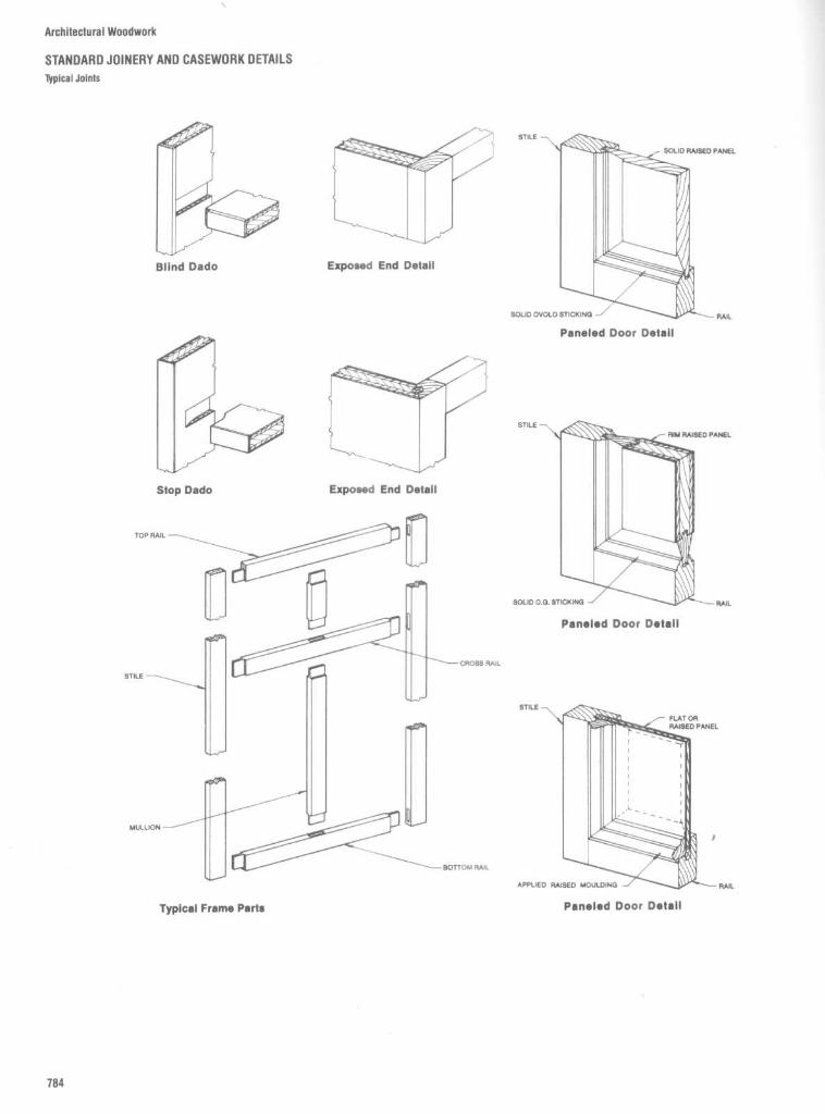
Architectural
Woodwork
STANDARD
JOINERY AND CASEWORK DETAILS
Typical
Joints

Architectural Woodwork
STANDARD JOINERYAND CASEWORK DETAILS
Cabinet Work
TYPICALCABINET CONSTRUCTION

Architectural Woodwork
STANDARD JOINERY AND CASEWORK DETAILSCabinet Work

Architectural Woodwork
STANDARD JOINERYAND CASEWORK DETAILS
Cabinet Work
Purpose
-ne following information outlines methodsassembly and installation of common
:abinet work, Solutions of typical problemsare presented without attempting to detailspecific cabinets .
Assembly
-ügh-grade cabinet and veneered work isassembled as far as possible at the shopJoints are glued and blocked, and sometimessecured with finishing nails or screws . Car-pentry and millwork are generally put to-gether with finishing nails if of soft wood, orwith screws if of hardwood . Hardwoodshould be drilled to prevent splitting beforeusing nails or screws, and heads should becountersunk and concealed bycover moulds,moulding quirks, or puttl, plastic wood, orother filler, colored to match the finish . Nonails, screws, or joints should be visibleunless they are intentionally incorporated indesign .
Shrinkage and warping
effects can be largelyeliminated by proper detailing and construc-tion . Wide flat surfaces (solid or veneered)should be made up of several narrow stripsglued and doweled, splined, or dovetailedtogether. Cleats may also be screwed orkeyed to backs of wide surfaces . Joints incorners, sheathing, etc , should be con-
cealed within quirks of moulds (as inmoulded tongue-and-groove) or return faces(shoulder joints) . Panels should be rigidlysecured on one side only, and are often leftentirely loose . Housed joints, not glued,permit panels to expand and contract withoutsplitting .
Large moulded surfaces
(such as cornices ormantels) should always be shop-assembledand delivered with scribe-moulds (see"Scribing" below) loosely tacked to as-sembled units.
Installation
All grades of woodwork should be preser-vative treated or back painted before erec-tion, preferably before delivery to the job.Satisfactory priming coats are aluminumpaint or white lead in linseed oil, thinned withturpentine or mineral spirits .
Preparation
On frame walls plaster may belimited to one or two coats, may be recessedbetween studs, or may be omitted . In thelatter case, building paper should be usedbetween woodwork and studs. On masonry,plaster may consist of one or two coats ormay be omitted. Masonry surfaces, particu-larly exterior walls, should be waterproofedor woodwork should be protected by a layerof waterproof paper and should always befurred out. When finish of the interior of
cabinets is plaster, either plain or canvascovered, the final coat of plaster is appliedafter erection of cabinet.
Grounds
of soft wood for attaching cabinetwork must be accurately located, are se-cured directlyto framing members orfurring,and must be concealed.
Blocking
of rough lumber should be erectedfor supporting raised floors and large orheavy cabinet work, if it can be concealed.Blocking must be accurately placed andsecured with nails .
Shimming Minor irregularities in blocking,furring, or placement of studs may be cor-rected by using shims (wedge-shapedpieces of wood, often shingles) to bringcompleted work to plumb and level lines.Shimming should be concealed.
Scribing is the practice of fitting edges ofcabinet work accurately to all irregularities offinish plaster, masonry, or other abuttingsurfaces . Wood mouldings, panel frames, orcabinet returns to be scribed should beprovided with a beveled edge .
Prefabricated woodwork is generally deliv-ered knocked down for assembly on the joband is erected similarly to custom-madework . Consult manufacturers' data .

Fig . 1
Inside surfaces of open shelf cabinets and behind glass are considered exposed forpremium grade and tops of tall cabinets and upper cabinets 6 ft above the floorthat are exposedfrom upper levels are considered exposed.
Architectural Woodwork
STANDARD JOINERYAND CASEWORK DETAILS
Plastic-Covered Casework
Casework Definitions
A. Exposed portions1 . All surfaces visible when doors and draw-
ers are closed .2. Underside of bottoms of cabinets over
4'0" above finished floor3. Cabinet tops under 6'0" above finished
floor or if over 6'0" and visible from anupper building level or floor.
4. Visible front edges of web frames, ends,divisions, tops, shelves, and hangingstiles .
5. Sloping tops of cabinets that are visible .6. Visible surfaces in open cabinets or be-
hind glass for premium grade only.7. Interior faces of hinged doors for premium
grade only.8. Visible portions of bottoms, tops, and
ends in front of sliding doors in customand premium grades only.
B. Semi-exposed portions1 . Shelves .2. Divisions .3. Interior face of ends, backs, and bottoms.4. Drawer sides, subfronts, backs, and
bottoms.5. The underside of bottoms of cabinets
between 2'6" and 4'0" above the finishedfloor.
6. Interior faces of hinged doors, exceptpremium grade.
7. Visible surfaces in open cabinets or be-hind glass for economy and customgrades and all rooms designated as stor-age, janitor, closet, or utility.
8. Visible portion of bottoms, tops, and endsin front of sliding doors in economy gradeonly.
C. Concealed portions1 . Toe space unless otherwise specified .2 . Sleepers .3. Web frames, stretchers, and solid
subtops.4. Security panels .5. Underside of bottoms of cabinets less
than 2'6" above the finished floor6. Flat tops of cabinets 6'0" or more above
the finished floor, except if visible from anupper building level .
7. The three nonvisible edges of adjustableshelves.
8. The underside of countertops, kneespaces, and drawer aprons .
9. The faces of cabinet ends of adjoiningunits that butt together.

Architectural Woodwork
STANDARD JOINERYAND CASEWORK DETAILSTypical Base Cabinet Details

Architectural Woodwork
STANDARD JOINERYAND CASEWORK DETAILS
Typical Upper Cabinet Details

Architectural Woodwork
STANDARD JOINERY AND CASEWORK DETAILS
Typical Drawer Details

Architectural Woodwork
STANDARD JOINERY AND CASEWORK DETAILS
Typical Flush Overlay Casework Construction

Architectural Woodwork
STANDARD JOINERYAND CASEWORK DETAILS
Typical Flush Overlay Casework Construction

Architectural Woodwork
STANDARD JOINERYAND CASEWORK DETAILS
Typical Flush Overlay Casework ConstructIon

Architectural Woodwork
STANDARD JOINERYAND CASEWORK DETAILS
Solid Core Wood Flush Doors
Fig . 7 Mat-formed wood particleboard core (5-ply constructionillustrated).
Fig . 6 Mat-formed wood particleboard core (7-ply constructionillustrated).
Fig . 9
Glued block core (5-ply construction illustrated).Fig . 8 Mat-formed wood particleboard core (3-ply constructionillustrated).

Architectural Woodwork
STANDARD JOINERY AND CASEWORK DETAILS
Solid Core and Hollow Core Wood Flush Doors
SOLID CORE WOOD FLUSH DOORS
Fig . 10
Framed block glued core (7-ply construction illustrated) .
Fig.11
Wood block lined core (7-ply construction illustrated).
HOLLOW CORE WOOD FLUSH DOORS
Fig . 12
Ladder core (7-ply construction illustrated) .
Fig . 13
Mesh or cellular core (7-ply construction illustrated) .

a.
FLUSH CABINET DOORS. All WIC Grades .
TYPE "1"Veneer/tape banding, 1/16" maximum.
TYPE "2"Solid banding.
3 Ply Skin
TYPE "3" - Medium Density Fiberboard .Banding not required for Economy andCustom Grades .Band required for Premium Grade.
b.
LIPPED CABINET DOORS .TYPE "4"
Veneer /tape
banding,
1/16"
maximum,required .
TYPE "5"Solid banding .
3 Ply Skin
TYPE "6" - Medium Density Fiberboard .Banding not required for Economy andCustom Grades .Band required for Premium Grade.
c .
STILE AND RAIL CABINET DOORS . All WICGrades.
TYPE "7", S4S Stop .
TYPE "8" . Solid Stuck .
TYPE "9", Moulded Stop .
d .
The top and bottom edges of sliding doors do notrequire an edge band .
Architectural Woodwork
STANDARD JOINERYAND CASEWORK DETAILS
Cabinet Door and Banding Types

Architectural Woodwork
STANDARD JOINERY AND CASEWORK DETAILS
Stile and Rail Joinery Details
Fig . 14
Full-height stile and rail raised paneling . Stile and rail wall paneling accented by raised panels creates a beautifuleffect of traditional architectural woodwork . Framed within the stiles and rails and accented by the shadow lines, thisconstruction offers limitless opportunities for various effects through the use of different wood species and veneer cuts . Eachdesign creates a unique atmosphere complimented by the finely proportioned paneling .

Architectural Woodwork
STANDARD JOINERYAND CASEWORK DETAILSPaneled Wainscot and Doors
Fig . 15
Flap paneled wainscot . Flat panels set within the frame of the stile and rail create a rich effect of traditional architectural woodwork .Different results can be produced through the use of veneer selections with transparent finish or painted finishes chosen by the architect or designer.
Fig . 16
Paneled doors . Stile and rail doors designed to accent the adjacent wall paneling whether traditional or contemporary, or used alone,beautify an entryway or area .

Fig . 17
Full-height contemporary raised paneling . This design, distinguished by its simplicity, is a contemporary expression of the stile and rail construction .
Architectural WoodworK
STANDARD JOINERY AND CASEWORK DETAILS
Raised Paneling

Architectural Woodwork
STANDARD JOINERYAND CASEWORK DETAILS
Sash, French, and Panel Doors
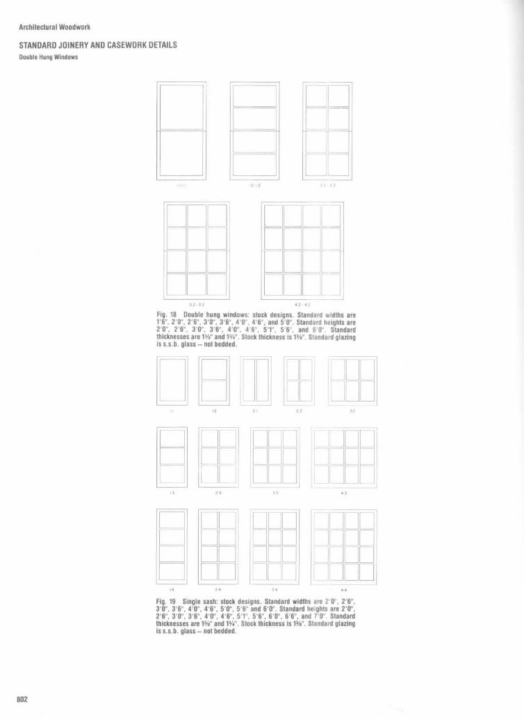
Architectural Woodwork
STANDARD JOINERY AND CASEWORK DETAILS
Double Hung Windows

Architectural Woodwork
STANDARD JOINERY AND CASEWORK DETAILS
Casement Windows

Architectural WoodworK
WOODWORK DETAILS
'Wood Paneling

Architectural Woodwork
WOODWORK DETAILSWood Paneling

Architectural Woodwork
WOODWORK DETAILSCorner Cupboard

Architectural Woodwork
WOODWORK DETAILSCorner Cupboard

Architectural Woodwork
WOODWORK DETAILS
Bookcases

Architectural Woodwork
WOODWORK DETAILS
Bookcases

Architectural Woodwork
WOODWORK DETAILSBookcases

Architectural Woodwork
WOODWORK DETAILSBookcases

Architectural Woodwork
WOODWORK DETAILS
Library Cabinets and Bookcases

Architectural Woodwork
WOODWORK DETAILSMiscellaneous Details

Architectural Woodwork
WOODWORK DETAILS
Trader's Wall

Architectural Woodwork
WOODWORK DETAILSTrader's Wall

Architectural Woodwork
WOODWORK DETAILSStorage Cabinets

Architectural Woodwork
WOODWORK DETAILSWardrobe

Architectural Woodwork
WOODWORK DETAILSBar Sink

Architectural Woodwork
WOODWORK DETAILS
Display Case

Architectural Woodwork
WOODWORK DETAILS
Display Case

Architectural Woodwork
WOODWORK DETAILSDisplay Case

Architectural Woodwork
WOODWORK DETAILSDisplayCase

Architectural Wooawork
WOODWORK DETAILS
Display Case

Architectural Woodwork
WOODWORK DETAILSWork Counter
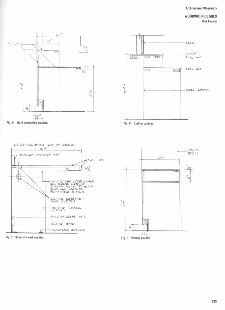
Architectural Woodwork
WOODWORK DETAILSWork Counter

Architectural Woodwork
WOODWORK DETAILSWork Counter

Architectural Woodwork
WOODWORK DETAILS
Overfile Cabinet

Architectural Woodwork
WOODWORK DETAILSOverfile Cabinet

Architectural Woodwork
WOODWORK DETAILSDisplay Cabinet

Architectural Woodwork
WOODWORK DETAILSCredenza

Architectural Woodwork
WOODWORK DETAILSPlanter and Storage Cabinet

Architectural Woodwork
WOODWORK DETAILSBook and Shawl Cabinet
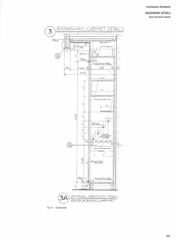
Architectural Woodwork
WOODWORK DETAILSBook and Shawl Cabinet

Architectural Woodwork
WOODWORK DETAILSStorage Shelves
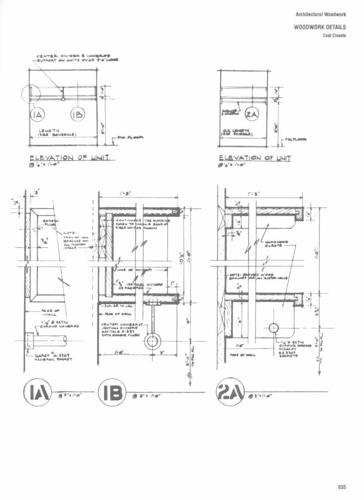
Architectural Woodwork
WOODWORK DETAILSCoat Closets

Architectural Woodwork
WOODWORK DETAILS

Architectural Woodwork
WOODWORK DETAILSBase Cabinets

Architectural Woodwork
WOODWORK DETAILS

Architectural Woodwork
WOODWORK DETAILS
Pantry Cabinets

Architectural Woodwork
WOODWORK DETAILSAttars

Fig . 16
Combination upholstered/wood seat . An
Fig . 17
All wood seat . Either solid wood or ve-upholstered seat with a wooden back (either solid or
neered seat and back . Generally the most expensiveveneer laminate).
option. Wood seats and back can be contoured forincreased comfort .
Fig . 19
Screens are adaptable for many uses in the sanctuary . They serve as modesty screens infront of the first row of pews, or they can be adapted for useas communion rails, as choir boxes, or aswainscoating .
Fig . 15
Fully upholstered seat . All exposed surfaces of the seat and back are fully upholstered .
Architectural Woodwork
WOODWORK DETAILS
Pews

Architectural Woodwork
WOODWORK DETAILS
Sanctuary Doors and Miscellaneous Details

Architectural Woodwork
WOODWORK DETAILS
Lectern

Architectural Woodwork
WOODWORK DETAILSLectern

Architectural Woodwork
WOODWORK DETAILSLectern

Architectural Woodwork
WOODWORK DETAILSLectern

A,i,,i ~ it!! : Acrchitectural :Woodwork
WOODWORK DETAILSBoardroom Table

Architectural Woodwork
WOODWORK DETAILSBoardroom Table

Architectural Woodwork
WOODWORK DETAILS
Bench

Architectural Woodwork
WOODWORK DETAILS
Stair Screen and Seat

Architectural Woodwork
WOODWORK DETAILS
Window Seat
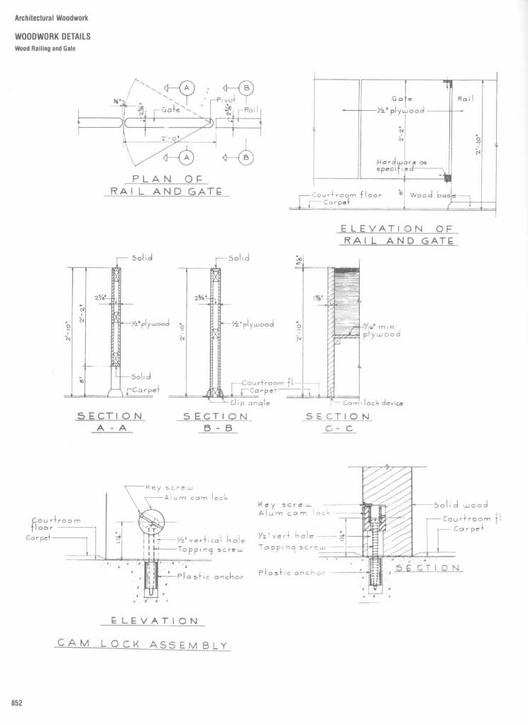
Architectural Woodwork
WOODWORK DETAILS
Wood Railing and Gate

Architectural Woodwork
WOODWORK DETAILSHidden Wood Door

Architectural Woodwork
WOODWORK DETAILSRaised Panel Wood Doors

Architectural Woodwork
WOODWORK DETAILS
Miscellaneous Details

Architectural Woodwork
WOODWORK DETAILSCornices

Architectural Woodwork
WOODWORK DETAILSCornices

Architectural Woodwork
WOODWORK DETAILSComices

Architectural Woodwork
WOODWORK DETAILS
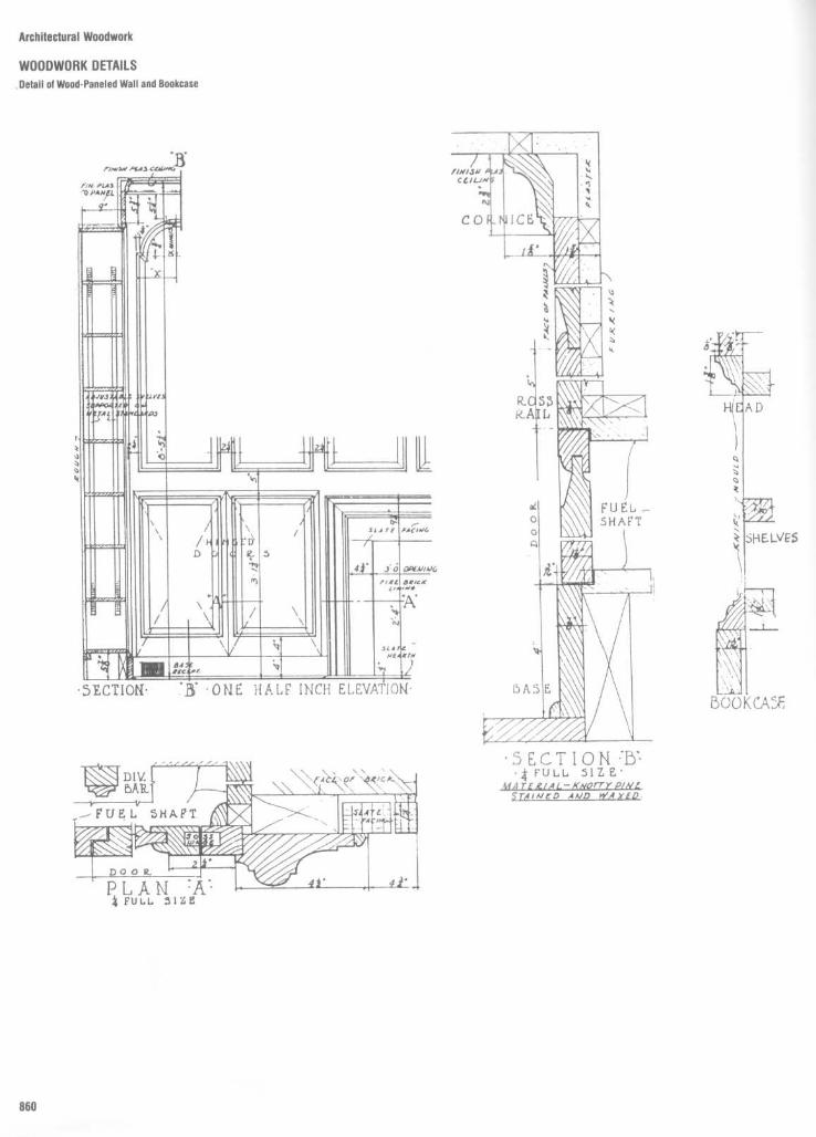
Architectural Woodwork
WOODWORK DETAILSDetail of Wood-Paneled Watt and Bookcase

Architectural Woodwork
WOODWORK DETAILS
Cornice and Baluster Details

Architectural Woodwork
WOODWORK DETAILSDIsplay Cases

Architectural Woodwork
WOODWORK DETAILSDisplay Cases

Architectural Woodwork
WOODWORK DETAILS
Bars

Architectural Woodwork
WOODWORK DETAILS
FINISHING MATERIALS
GENERICTYPE RECOMMENDED USAGE CHARACTERISTICS
System klLacquers For all wood surfaces except medium to Good coverage ; Easy to apply ; Sands easy ;
heavy acid areas; Interior use . Poor water resistance .
Catalyzed Laequcrs For wood surfaces requiring medium acid Tough wearing surface ; Good waterresistance ; Interior use. resistance; Can be repaired .
System N2Varnishes For all wood surfaces ; Interior use; Exterior Good build; Tends to amber with age; Slow
use - spar varnishes. drying .
Conversion I-or all wood surfaces ; Some acid Good build and solids ; Can be repaired .Varnishes resistance ; Interior use .
System q3Polyurctltauc For all wood surfaces ; Interior use. Tough surface; Excellent wear and abrasion
resistance ; Can be repaired .
Catalyzed For all wood surfaces ; High acid resistance ; Tough surface; Excellent wear and abrasionPolyurethane Interior use. resistance ; Can be repaired .
System a4Epoxy For all wood surfaces ; High acid resistance ; Very hard surface; Excellent wear and
Interior use. abrasion resistance ; l.imited put life Highwater resistance .
System N5Penetrating Oils For all wood surfaces ; Performs well on Easy to apply ; Makes touch-up easy ;
Oak, Teak, Walnut, etc. Average wear and abrasion qualities ; Easyto repair .
System #6Synthetic Enamels Most wood and wood product surfaces ; Good coverage ; Tough wearing; Call be re-
Interior use; Most colors available . coated or repaired ; Easy to apply .
System #7
- Vinyl Lacquer For all wood products ; Interior use; Light Tough surface; Good wearing; Resists lightacid resistance . chemicals.
Catalyzed Vinyl For all wood products ; Interior use; Tough surface; Good wearing; Repairs notExcellent for residential kitchens, etc . ; easy .Better acid resistance .
System a8Dire Retardant Fur surfaces of wood products requiring Leaching will result if exposed directly toCoatings flame spread protection . (See WIC high humidity or direct water . Can be
(Iniunescent) Technical Bulletin No . 423 - Section l9 .) coated with compatible overcoat system orInterior use only . waterproofing materials. Available furUL Rated-UL-723 ; NFPA-255 ; and transparent and opaque finishes .ASTM E-84 ; Tested for flame spread, fuelcontributed, and smoke developed.

Architectural Woodwork
CORNICES AND MOULDINGSDeep Sculpt and Crown Mouldings

Architectural Woodwork
CORNICES AND MOULDINGSCrown Mouldings

Architectural Woodwork
CORNICES AND MOULDINGS
Crown Mouldings

Architectural Woodwork
CORNICES AND MOULDINGSDoor Trim Mouldings

Architectural Woodwork
CORNICES AND MOULDINGSMiscellaneous Mouldings

Architectural Woodwork
CORNICES AND MOULDINGSCrown Mouldings

Architectural Woodwork
CORNICES AND MOULDINGSCrown Mouldings

Architectural Woodwork
CORNICES AND MOULDINGSMiscellaneous Mouldings

Architectural Woodwork
CORNICES AND MOULDINGSMiscellaneous Mouldings

Architectural Woodwork
CORNICES AND MOULDINGSMiscellaneous Mouldings

Architectural Woodwork
CORNICES AND MOULDINGSBase Mouldings

Architectural Woodwork
CORNICES AND MOULDINGS
Base Mouldings

Architectural Woodwork
CORNICES AND MOULDINGSCasings

Architectural Woodwork
CORNICES AND MOULDINGS
Casings

Architectural Woodwork
CORNICES AND MOULDINGSgeaded Casings

Architectural Woodwork
CORNICES AND MOULDINGS
Cove Mouldings

Architectural Woodwork
CORNICES AND MOULDINGSPanel Mouldings

Architectural Woodwork
CORNICES AND MOULDINGSChair Rait Mouldings

Architectural Woodwork
CORNICES AND MOULDINGSHandralls, Balusters, and Rounds

Architectural Woodwork
CORNICES AND MOULDINGS
Clam Shell and Stop Mouldings

Architectural Woodwork
CORNICES AND MOULDINGS
Hand-Carved Brackets
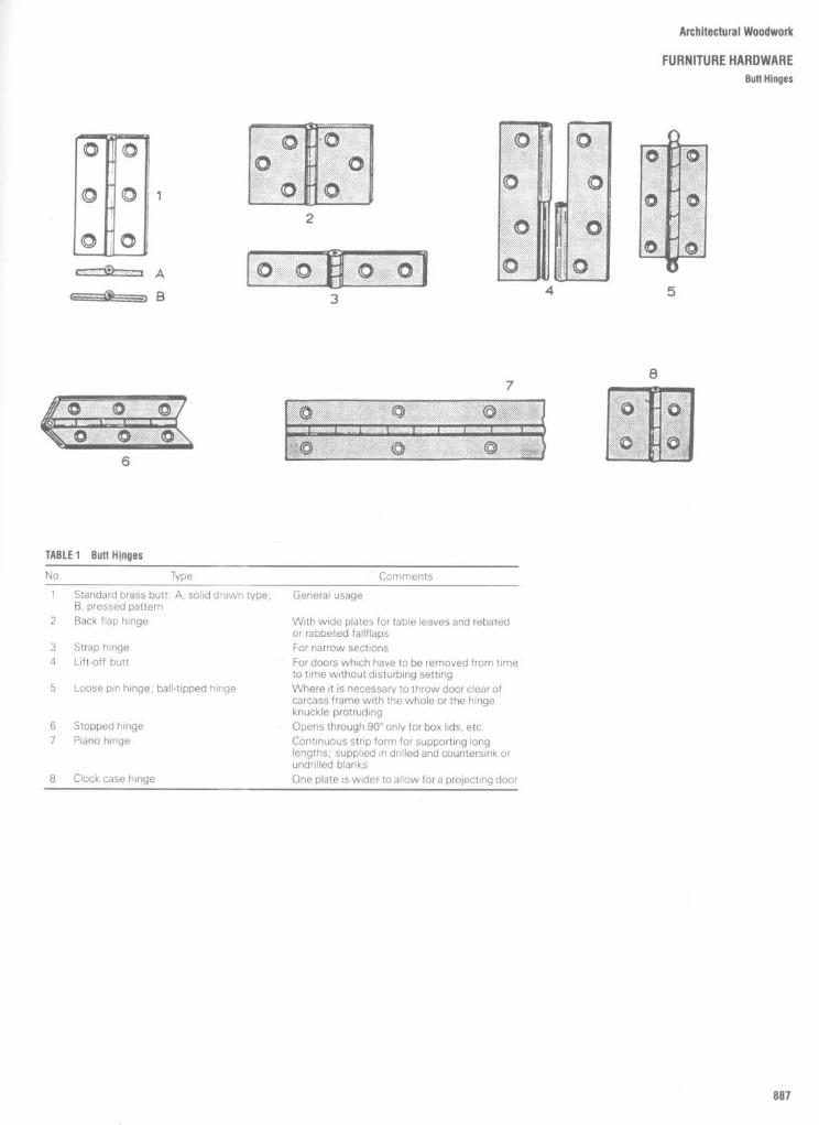
Architectural Woodwork
FURNITURE HARDWAREButt Hinges
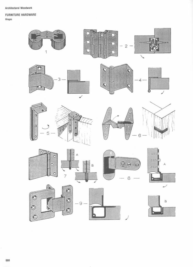
Architectural Woodwork
FURNITURE HARDWAREHinges

Architectural Woodwork
FURNITURE HARDWAREHinges
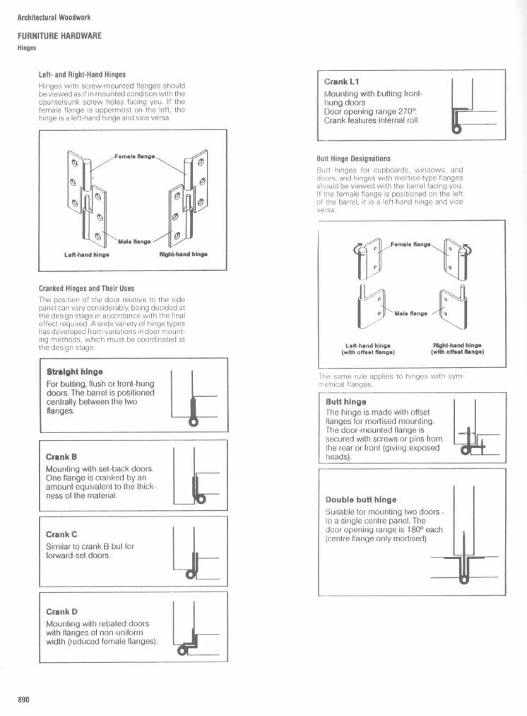
Architectural Woodwork
FURNITURE HARDWAREHinges
Left-and Right-Hand Hinges
Hinges with screw-mounted flanges shouldbe viewed as if in mounted conditionwith thecountersunk screw holes facing you . If thefemale flange is uppermost on the left, thehinge is a left-hand hinge and vice versa.
Butt Hinge Designations
Butt hinges for cupboards, windows, anddoors, and hinges with mortise-type flangesshould be viewed with the barrel facing you .If the female flange is positioned on the leftof the barrel, it is a left-hand hinge and vicevpr-a .
Cranked Hinges and Their Uses
The position of the door relative to the sidepanel can vary considerably, being decided atthe design stage in accordance with the finaleffect required . Awide variety of hinge typeshas developed from variations in door mount-ing methods, which must be coordinated atthe design stage.

Architectural Woodwork
FURNITURE HARDWAREFolding Table and Flap Hinges

Architectural Woodwork
FURNITURE HARDWAREMitred and Concealed Hinges
An all-metal mitred hinge, specially designed toenable door and carcase edges to meet at an angleof d5 °.
CONCEALED HINGES
Specimen installation of a butting, flush-fittingcupboard door Doors may, however, be set backor forward if preferred, provided the housing re-cesses are appropriately offset . ii doors are setback, care must be taken to ensure that theopening angle is restricted as little as possible .
Specimen installation of a butting, front-hungdoor, fitting flush with the cupboard side in theconventional manner . Doors may, however, behung with inset edge d preferred, provided thehousing recesses are offset accordingly. It isimportant in such cases to ensure that centredoors are not mounted with groove gap clear-ance.
Specimen installation of a butting, front-hung,flap-type door . On opening, the flap projectsdownwards by its own thickness. Thus, if doorsor other panels are situated below the flap, adegree of clearance exceeding the flap thicknesswill be necessary .
Specimen installation joining two panels. In thisway folding doors can be constructed for furni-lure or room dividers :

Architectural Woodwork
FURNITURE HARDWAREPivot Hinges

Architectural Woodwork
FURNITURE HARDWAREGlass Door Hinges

Architectural Woodwork
FURNITURE HARDWAREFlap Stays with Brake

Architectural Woodwork
FURNITURE HARDWARELid Stays

Architectural Woodwork
FURNITURE HARDWAREDrawer Runners

Architectural Woodwork
FURNITURE HARDWAREMagnetic and Spring Catches ; Bolts

Architectural Woodwork
FURNITURE HARDWARELocks

Architectural Woodwork
FURNITURE HARDWAREShell Supports

Architectural Woodwork
FURNITURE HARDWARE

Architectural Woodwork
FURNITURE HARDWAREFurniture Glides


Specialties
INTRODUCTION
In most instances, the design process requires a knowledge of, or at the
rery least, an awareness of, certain specialized elements that can contribute
heavily to the success or failure of a project in terms of aesthetics or function,
:)r both . These elements may take the form of manufactured "off-the-shelf"
oroducts or consist of design theories, standards, and guidelines for certain
areas of expertise . Accordingly, this section deals with ten such elements,
"anging from plantscaping to accessories.Information can be found concerning the height, spacing, and diameter of
ndoor trees and floor plants . Also included are planting standards, details, and
maintenance information . The section dealing with signage and graphics
provides information on signage systems, symbols, mounting heights, and
locations. Other sections provide data on audio-visual systems, including
projection room layouts and details, and auditorium seating arrangements and
sightlines . The section dealing with security includes information on door and
window hardware, mailbox rooms, lighting, and security systems . Still other
sections provide information on color theory and window treatments,
including draperies and curtains, shutters and shades, and rods, holdbacks,
and ties .

Specialties
PLANTSCAPINGDesign Guidelines
DESIGNING WITH PLANTS
Any successful design uses plants that arecompatible not only in an aesthetic designsense, but also in their growing require-ments . No matterhowbeautiful the design, ifneighboring plants are not matched to thecorrect growing conditions, parts of the de-sign will either deteriorate or require elabo-rate maintenance. The aesthetic design con-siderations involve choosing the propervariety of plant textures, heights, and spacingto give the desired effect . The growingconsiderations involve the proper matchingof light intensity, soil, and water, as well asproper container size, to the plant environ-mental requirements .
Of all the growing conditions, the mostimportant is the light intensity. It is easy tounderestimate the amount of available light,since the human eye can easily see in 20footcandles of light, while even the plantneeding the lowest light requires 50 to 75footcandles to remain healthy. If the lightintensity is to be below 100 footcandles,even these "low-light" plants must be slowlyacclimatized prior to installation .No matter if the space to be planted is a
small office, a large interior garden, or acafeteria, the first step is to ascertain theactual level of the existing or planned lighting .To allow maximum creativity in the plantingdesign, the light intensity should be consid-ered in the initial planning stages, especiallyin large areas such as those in shopping mallsor corporate interior gardens. Adding theneeded lighting fixtures after the initial elec-trical installation is often expensive or impos-sible. In smaller-scale situations, such asoffices or homes, extra light fixtures shouldbe added or the plants should be chosenaccording to the available light. If the plantsdo not have the proper light intensity, theywill die. The lower the light intensity belowthe minimum needed by the species, thefaster they will do so .
Since the light source (incandescent, fluo-rescent, sun, or other) is not important, butthe light intensity is, accurate intensity mea-surements are essential. For these measure-ments we recommend the General ElectricModel 213 or 214 light meter or its equiv-alent. The measurements must be made atthe level of the plant foliage ; they must bemade several times a day on several daystypical of the location if sunlight is used ; andthey must take curtains, tinted glass, andother light-shielding devices into account .Only light hitting the top of the leaves iseffective . While underlighting with spotlightscan create dramatic effects, it does very littleto help the plant.
After the light intensity is determined, theplants should be selected from the appropri-ate light-level group (see Fig. 7), consistentwith the design aims . Plants that will begrowing near one another should also havesimilar water requirements (also given inFig . 7) . If plants with different watering re-quirements must be close, they should bekept in their own growing containers so theycan be watered separately.An interior planting designer creates the
mood through the interplay of plant texture
and plant height, working only with thoseplants that will live under the predeterminedlight intensity. Color cannot really be used asa design element, since the average interiorlight intensity is seldom more than 100footcandles and brightly colored plants orblooming flowers need up to 1000 footcan-dles . If flowering plants are used where thelighting conditions are normal, they will gen-erally have to be replaced every few days .
Plant Texture
The good designer will provide for designvariety through the clever use of plant tex-ture . The term is used here to describe thegeneral structure, shape, and appearance ofthe plant, regardless of height . It includes thesize, shape, edging, and thickness of theplant's leaves, as well as its overall shape andthe arrangement and number of leaves onthe plant.
Five general rules concerning textureshould be kept in mind .
1 . Juxtapose fragmented foliage (such asthat of a palm) with solid foliage (say, that of adracaena).2. Avoid too much of the same type of
foliage (e .g ., large flat leaves) in one area,unless a border or hedge effect is desired.3. An exception to these previous rules on
groupings is the palm . Although all palmshave similar foliage, they vary slightly in colorand interest, so that different types of palmsmaybe planted together.4. To create interest, mix small-leaved
with large-leaved plants, and narrow-leavedwith broad-leaved plants .5. When using plants as specimens, es-
pecially as interior design elements in officesor homes, pick the plant with the backgroundfabric, carpet, or wallpaper in mind . Forexample, a "busy" foliage plant will fight witha "busy" fabric .
Plant Height
Plant height not only determines the scale ofthe design, but it adds variety to the plantgroupings . There are six general rules regard-ing plant height selection to keep in mind .
1 . In the plant grouping, build up with thelow plants in front . If the grouping can beseen from all sides, the grouping must bewell balanced throughout and built up to thecenter height .
2. If a plant has canes with no lowerfoliage, try to place the lower plants in frontto conceal the absence of foliage of the tallerplants in the rear.
3. Uneven sizes throughout a groupingadd more interest than consistent levels offoliage .4. If a single plant is desired to hide a
column or some other object, be sure thatthe plant height, including its container, isabout three-fourths the height of the objectto be concealed .
5. Keep the scale of the surroundings inrnind when choosing the plant height . A3-foot plant is fine next to a desk, but a plantof at least 6 feet should be selected if it is tobe viewed when entering a room .
6 .
By convention, interior plant heights are
measured from the bottom of the root ball orplanter, while exterior plant heights are rnrersured from the top of the root ball . Thereason is that interior plants are usuaikplaced in a containeror raised planter, and tretotal available height from floor to ceiling Rfixed.
Plant Spacing
Under certain conditions, the plants of ar-interior landscaping design will grow. The-fore, any possible change in the plant s __must be considered by the designer. If t-,elighting intensity is at or below the recor--mended level, there will be little or no plan-growth and the plant size and relationshipswill change little over time . If the lightrnçintensity is well above the required levethere will be plant growth, with differe^-plant species growing at different rates.
Unlike outdoor plants, indoor tropicaiplants seldom grow outward ; most of theirgrowth occurs upward . The main exception_are the Ficus family, the schefflera, and tryPhilodendron Sellourn, which will spreacsomewhat outward . If a full plant designdesired, the required number of plartsshould be placed close together at the timeof installation since future growth will seF-dom fill in the bare spots.
Even if the light intensity is high enougrbefore the plant can grow significantly, -root system must be able to expand . Thusthe best way to ensure that the size rela-tionships of the plants do not change is tokeep them in their original growing con-tainers and not to replant them into a growingmedium . If they are kept in the originacontainers, they will become pot-bound ancfuture growth will be automatically limited .
Plant material is sold on the basis of heigh".or growing-container size, and one must befamiliar with the particular species to knoAwhat the spread will be . For each plantspecies considered here, Fig. 1 lists theheight range for each plant in each standaregrowing-container size and gives a recom-mended minimum center-to-center plantspacing. This recommended spacing isbased on experience with the plant's branch-ing habits and growth patterns and will givea full plant design . If an open or a less fudesign is called for, the spacing should beincreased.When the plants are to be displayed in
individual planters or decorative containers,each plant, still in its growing can, is placeddirectly into the planter or container, on top ofa layer of drainage material of the appropriatedepth However, many standard plantershave lips that reduce the interior diameter toless than the overall diameter. This innerdiameter should be larger than the growingcans diameter so that the plant can be placeddirectly into it without being repotted andrisking the attendant danger of root damageTo emphasize this requirement, Fig. 2 givesthe standard planter diameter needed foreach standard size of growing container. Thesize of the lip changes when a nonstandardtype is used . If space is limited, this measure-ment should be carefully checked.

Specialties
PLANTSCAPINGPlant Height, Spacing, and Diameter

Specialties
PLANTSCAPINGPlant Height, Spacing, and Diameter

Specialties
PLANTSCAPING
Plant Height, Spacing, and Diameter
Fig . 2
Planter selection . These recommendationsare based on the fact that most standard plantershave either a 1-inch lip or no lip at all . Because thegrowing cans sometimes have ridges or havebecome deformed, it is always best to allow for alittle extra leeway, even for planters with no lip .Some manufacturers, however, put 2-inch lips ontheir planters, a possiblity that should be checked . Ifthe planter is an automatic watering type, the insideand outside diameters will be quite different,depending on the manufacturer.

Specialties
PLANTSCAPING
Design Guidelines
10
Writing SpecificationsThe interior landscaping business is verycompetitive, and a common practice is forthe architect or designer to send out thelandscaping specifications for bids . Unlessthe specifications for the job are well-written,however, there are many ways for the con-tractor to cut corners and still be within thespecifications . Consequently, the final in-stallation may not be what the designer hadin mind . The lowest bid is not necessarily thebest bargain, unless the specifications arevery tightly written or unless the architect isdealing with a well-established landscapecontractor with a reputation for high-qualitywork .The following are some suggested guide-
lines to use in writing specifications . If theyare observed, the bids received will accu-rately reflect the design requirements of thejob.
1 . Specify the plant heights within a 6-inchbracket. For example, designate 5 to 5'/z feetor 5'/2 to 6 feet . If the specification weresimply "5 to 6 feet;' the supplier could use all5-foot plants, which are considerably lessexpensive than 6-foot plants .2. For corn plants, dwarf dragon trees, and
the like, specify the number of canes andapproximate number of foliage heads, aswell as the height . The difference in costbetween a two-cane and a three-cane cornplant of the same height is not minor.3. For reed palms, bamboo palms, and the
like, specify the number of stems desired,five to six being medium full .4. For the green dracaena and white-
striped dracaena, list the number of mainfoliage stems desired. They range from oneto three stems.5. For ficus trees, it should be specified
whether the bush style or standard tree styleis desired . In the bush style, the plant hasmultiple stems (ranging from two to fivein number) branching out from the baseof the plants . The standard tree or "lollipop"style has one main 5- to 6-foot stem with asheared, ball-shaped foliage head .6. Small plants should be specified as to
single plants or combinations or severalplants . Examples are dumb cane, Chineseevergreen, and white flag .7. If ivy trailers are desired, their length
should be specified. The trailers take up toeight months to grow, depending on thelength, so the designer must plan for theseup to a year before installation . Examples aregrape ivy, swedish ivy, golden pothos, com-monphilodendron, and wax plant.8. Specifications should call for plant
cleaning and spraying before installation .9. Perlite should be specified as the
drainage material for both planters and deco-rative containers . Styrofoam, which is muchcheaper, is often used but has little long-termvalue.
10 . The amount of ingredients in largeplanters (soil mixture, drainage material, soilseparator) should be specified, as should thecomposition of each of the ingredients .
11 . If bark chips, moss cover, or other soilcoverings are desired, they should bespecified .
12 . Special attention should be given tothe description of specimen plants, includingthe number of heads, stems, or canes, andany unusual stem structure that is desired . If
canes with character (such as angle andpeculiarity of growth), tufts of foliage atvarious heights, or other unusual featuresare wanted, they should be specificallymentioned.
13 . If the landscape contractor will notmaintain the plants after installation, provi-sion should be made for a training programfor the maintenance crew. Also, the contrac-tor should provide for two weeks' initialmaintenance of the plants and replacementof any that fall below specifications duringthe period .
14 . If the landscape contractor is to main-tain the plants after the installation (usuallythe best all-around solution), such an agree-ment should be reached before the plants areinstalled and a maintenance contract shouldbe signed . This contract should include aprovision for the replacement of any plantthat falls below specifications because offaulty maintenance. This stipulation gives thecontractor incentive for professional-qualitymaintenance.
15 . If a large garden is planned and thelandscape contractor is given design respon-sibility for it, the contractor should provide afloor plan of the garden for the designer'sapproval, before the installation .
16 . If the architect or designer providesthe landscape contractor with a detailedplanting floor plan and the contractor finds itimpossible to meet all the specifications(because of unavailability of certain species,etc.), the contractor and the designer orarchitect should agree in writing on anychanges.
USE OF INTERIOR PLANTS ANDPROCEDURES
The general rule of interior planting design isto vary the plant heights, shapes, and tex-tures to give the desired design feelingconsistent with the available light level andplanting space. The bestwayto learn to applythis rule to specific situations is to studysuccessful designs.
Interior planting designs have usually beenfound to fall into one of two categories : (1)interior gardens, both large and small, suchas those seen in residential and hotel lobbies,corporate headquarters reception areas, andenclosed shopping mall public spaces, and(2) open plan or specimen design, like officelandscaping designs and designs that useindividual plants as living sculptures . In bothcategories of design, the main requirementsto be considered are the available light inten-sity, the scale of the design, and the client'swishes and budget . After these basic re-quirements are determined, however, thedesign considerations are somewhat differ-ent for the two types of design .
Interior Gardens
Interior gardens are planting areas, some-times contained in built-in planters, that havea variety of plants and that convey theirdesign feeling through plant arrangementsrather than through individual plant spec-imens . Small gardens generally contain onlya single grouping of plants, act as a singledesign element, and have uniform lighting
and watering requirements throug ",autLarge gardens have a variety of plant g--uwings and varying design feelings among 71mgroupings, and they can encompass areas ardifferent lighting and watering requirerrSince any garden conveys its effects throipthe juxtaposition of different plants, a arildominant plant cannot be considered a gwden from the design point of view, even 4 r. ain a built-in planter with ground-cover p,arrs.
In designing any built-in planter, erKxrgrplanter depth must be provided to alloA reroot ball or the planting can to be covewith soil and to rest on 4 to 8 inches mirdrainage material . Since soil and gravel amexpensive, it is best not to overdesigr -itplanter, by making it larger than necessaryand not to buy too much soil to fill in betweenthe plants . (For example, a depth of 11/2 tc Zfeet is usually enough for most small galdens.) Figure 1 lists the size of the growr^rrcan for different sizes of plants of ea:species. The depth of the largest grown,can, plus the depth of the drainage maters,yields the minimum planter depth for regarden . The volume of the planter minus t,*total volume of all the growing cans indicatesthe amount of additional soil and drainagematerial to be provided .
If the planter is already in place, its dep,~^may limit the size of the plants that maybeused . Since soil must reach to the top of theroot ball or can, the only way to utilize tooshallow a planter is to put the large plant jrthe center and to build up from the edgeinward . The planter must be wide enough ".cslant the soil gradually so thatthe slope is nottoo great .
Small gardens
While a garden may be largeenough to have only a single design functiorthat function can be quite varied, providedthatthe lighting intensity is appropriate . It carserve as a small glen or a space separator, ofit can be simply a large decorative planterThe garden can be airy and open or it can bedense and closed . Planter depth of 1'/2 to 2feet is usually sufficient .
Also, some small gardens can be designedto be changed with the seasons. Often,flowering plants, such as chrysanthemumsor azaleas, are used, butthe plants mustthenbe replaced every twoweeks. If the seasonalor flowering plant changes are desired, theplants should be left in their containers sothat they may be easily moved. Some careshould be given to the planter design so thatthe growing cans are not obvious and do notdetract from the arrangement.
Creative additions of volcanic rocks, smallponds, or fountains can be quite attractiveand set off and enhance the plants . However,with the usually limited space in the smallgarden, these additions can produce acrowded or overdone appearance . Over-crowding will give a jungle effect that is rarelydesired .
Just as in other design fields, good propor-tion and good sense will create a pleasingdesign that is neither overlooked oroverbearing .
Large gardens Large gardens are simplylarger versions of small gardens, but theirvery size opens up more design possibilities,since they may be subdivided into relatedsections . The shape, height, and texture ofthe planters may be varied from section to

Specialties
PLANTSCAPINGPlant Use and Procedures
section . The plants may be chosen to reflect.arying design moods and functions . Theighting and watering requirements may dif-=er between sections . In fact, variety is often-ecessary for good large-garden design,s,nce a large mass of similar plants or plantgroupings will create the impression of a-monotonous forest or field .Because large indoor gardens usually are
^ areas of high ceilings, the light level mustoe very carefully considered . Just the pres-ence of windows or skylights does not guar-3ntee enough light . In addition, if the lightsources are distant from the plants, the tallerolants may effectively block some of the light'rpm reaching the lower plants and foliage .When large areas are to be planted, there
s a tendency to use rocks, pools, gravel, or=ountains to cut down the plant costs andsimplify the maintenance . Care is essential+vhen using these elements to prevent theplant arrangement from looking bare andsterile .
Large gardens are most commonly used inshopping malls . The skilled designer will takethis illumination into account, as well asdesign the garden to enhance the shopper'sview of the stores .The designer will always remember that
arge gardens achieve their effectiveness byooth the proper variation of plant groupingsand the proper variation of plants within thegroupings .
Procedures for planting gardens As pointedout earlier, a successful garden needs properplanting, since improper procedures can in-flict severe damage . Correct planting in-volves not only correct technique and designbut also correct organization .The techniques of proper drainage, spac-
ing, and handling will ensure that the plantsremain healthy once they are installed . Expe-rienced supervision of the installation staffwill be important in this regard, since a largeinstallation of expensive plants is no place forthe on-the-job training of the supervisorProper planning and organization will
ensure that the plants remain healthy be-tween unloading and planting . If the plantsare left on an unheated loading dock or storedin an unlighted or unheated room until theyare installed, irreversible damage may occur.
Drainage Overwatering of plants leads toroot rot and is often more harmful thanunderwatering . To minimize this danger, theplanter or container should be installed withproper drainage . The simplest technique is toprovide a porous reservoir below the plantingsoil ; any excess water will then drain into itfrom the root ball and be slowly fed back tothe soil as the soil dries out .
To prepare the planter or decorative con-tainer, the drainage material is poured intothe bottom and leveled . The plant growingcan is placed on top of the drainage layer andsurrounded with more of the drainage mate-rial . For the smaller plants (in pots 6 inches orless in diameter), a 1-inch depth of drainagematerial is usually enough . For the largerplants, a layer of 3 to 4 inches is suggested .For very large gardens, about one-third of theplanter depth should be the drainage layer,provided it leaves enough room for the rootball or planting can .The drainage material can be perlite (a
readily available synthetic material) alone or
mixed with small pebbles or gravel . Theperlite is suggested since it is porous enoughto feed back the excess water to the soil asthe soil dries out . If only gravel or pebbles areused, the excess water will sit and stagnatein the reservoir and will not be fed back to theplants .
Even with the proper drainage layer, over-watering is possible if so much excess wateris used that it fills up the reservoir. The waterlevel in a small container can be determinedby tapping the container at various intervalsand listening forthe change in sound . In largeplanted areas, it is wise to provide for "dip-stick" readings of the water level . To takesuch a reading, rigid hollow plastic tubes,with a cloth over their lower ends, are"planted" at intervals along with the plants .The hollow tubes reach from the top of thecontainer to just above the drainage layer andthe cloth on the bottom prevents soil ordrainage material from entering the tube . Adipstick is lowered into the tube until ittouches the cloth . If the stick, upon removal,shows more than Yz inch of water, there is toomuch water in the bottom of the planter.
If gravel is used as part of the drainagematerial, it should be 3/s inch to Yz inch indiameter. Under no circumstances shouldlimestone be used, since it is alkaline and willraise the pH of the water to a level that is toohigh for most tropical plants .
Soil separator If the plants are removedfrom their growing cans and replanted ingrowing soil, it is usually best to use a soilseparator between the drainage layer and theplanting soil . The separator is a semiporoussheet, often composed of fiberglass wool,which serves to keep the soil from falling intothe drainage material . If the separator is notused, soil will clog the drainage material .Fiberglass wool of building material gradeshould not be used, as it contains chemicalsthat will damage the plant (Fig . 3).
TOPSOILr i~r,r�
Fig . 3
Soil separation .
SOIL SEPARATOR
Planting medium
Because the root systemsof tropical plants are much finer than those ofoutdoor plants, pure topsoil is too heavy andtoo easily compacted to be used as a plantingmedium . It will constrict the plant roots andwill retain too much water.
For the common tropical plants discussedhere, we recommend the use of the foliageplant mix developed by Cornell University.Because it is easiest to calculate the quantityof needed soil in terms of the volume of theplanter to be filled, the formula given here is
for 1 cubic yard of soil . For conversion pur-poses, 1 cubic yard equals 21 .7 bushels, 765liters, or 27 cubic feet .
Sphagnum peat moss : 1/2 cu yd =383 litVermiculite #2 : Y4 cu yd =191 litPerlite, medium fine : 114 cu yd =191 litGround limestone, dolomitic : 0.85
gal =13,5 cup = 3 .2 litSuperphosphate 20 percent solu-
tion : 0 .21 gal =3.4cup=0 .79 lit10-10-10 fertilizer : 0 .32 gal = 5 .1
cup= 1 .2 litIron sulphate : 0 .11 gal =1 .7 cup= 0.41 litPotassium nitrate : 0 .11 gal=1 .7
cup= 0.41 litWhile this Cornell foliage plant mix gives
the best all-around results, a simpler mix thatgives good results in most cases is asfollows :
'h by volume sterilized commercial mixof peat moss and vermiculite
'/3 by volume sterilized topsoil'/3 by volume perlite
This mix is particularly effective for con-tainer planting . If it is to be used in a largergarden planting, such as a shopping mallgarden, more perlite should be added forimproved drainage .The peat and topsoil mix is considerably
heavier than the Cornell mix and both areheavier wet than dry. If the garden is notsituated at grade level, this weight can be animportant consideration . Figure 4 givesguidelines to be used in estimating theweight of the planting medium .
Planting organization The basic ingredientsfor a large planting installation are drainagematerial, planting medium, soil separator,plant material, material-handling equipment,light, water, and labor Organization of allthese ingredients is important since everyone must be ready and available for a suc-cessful installation . Arrangements for allthese factors should be made ahead of time,and they should be ready and waiting whenthe plants are delivered .The amount of interior volume in the
planters and containers determines theamount of needed drainage material, soilseparator, and planting medium . If detailedblueprints are not available, actually measur-ing the planters is generally a good way toobtain this volume . The relationship betweenplanting medium, drainage material, and soilseparator can be determined using the guide-lines of the previous subsection . If the plantsare to be left in their cans (as generallyrecommendedl, the space between theplants is filled with drainage material . If theyare removed from their cans, the spacebetween plants is filled with planting me-dium . In either case, the amount of volumedisplaced by the plants is simply the sum ofthe volume contained in the growing cans .Information for each standard size of growingcontainer is given in Fig . 5 .The installation should not be starred un-
less all lights and water connections areoperating, as the plants will need both lightand water during the installation - especiallythe light . If the plants are delivered dry, theyshould be watered in their cans unless theyare to be planted at once and wateredimmediately after planting . If the plants areremoved from their cans and placed into dryplanting medium, they and the planting me-dium should be thoroughly watered immedi-

Specialties
PLANTSCAPING
Plant Use and Procedures
ately afterward.Fewer design mistakes will be made if the
plants are installed one section at a time,under the direction of a supervisor familiarwith the design of the section. If the installa-tion is in an office building, it may be neces-sary to arrange for a workroom and a freightelevator with access both to the loading dockand the workroom . Depending on the exactarrangements, a crew of four to six workersper supervisor is generally optimum.
It is recommended that each section beplanted in the following order First, leftoverbuilding material and other debris are re-moved from the planting areas. Second,drainage material is added to the properdepth and leveled. Third, the plants, either inor out of their growing containers, are placedon top of the drainage material and the soilseparator if present, and arranged accordingto the design . The spaces between theplants are then filled in with drainage materialor planting medium, depending on whetherthe plants are in or out of their growingcontainers . If planting medium is used, itshould be lightly compacted to prevent itssettling later (If the light intensity is belowspecifications and periodic replacement ofthe plants is expected, the plants should beleft in their cans .)
After the spaces between the large plantshave been filled in, the groundcover, if any, isplanted . The use of decorative bark or marblechips on top of the soil is not recommendedas they easily mix with the soil and are hard toremove if the plants are replaced .
After all the spaces have been filled, theplants should be thoroughly watered and themaintenance schedule begun. If dry plantingmedium is used, it should be watered thor-oughly several times during the first week toensure that it is completely wet.
Removing plants from cans or burlap Ahealthy root system is necessary for themaintenance of a healthy plant. It is the new,very fine, feathery roots that are the mostimportant and also the most easily damaged .This damage is very likely if the soil betweenthe fine roots is dislodged in the course ofrepotting. Whether the tropical plants aredelivered in growing cans or with their rootswrapped in burlap, the root system must behandled with care .The best procedure for removing a plant
from its container is to lean the pot on itsside, tap on the container sides and bottom,and carefully slide out the plant. In largecontainer-grown plants (in 17-inch or largercans), the root system may be held verytightly in the can. In this case, a can cutter,which works on either metal or rubber cans,maybe the most gentle way of removing thecan . Once the can is removed, the root ballof soil and roots should be scored by making1/4-inch-deep vertical cuts at 3-inch intervalsaround the root ball from top to bottom . If thecan removal and ball scoring are done nearthe planting site, the exposed root system issubjected to minimum handling .Very large plants and trees are frequently
field-grown rather than container-grown . Theroot balls of such plants will come wrapped inburlap . When planting them, only the upperhalf of the burlap should be removed. Thelower portion will disintegrate in the soil afterthe plant is installed .
Rock formations and decorative pools
Naturalelements, such as rock formations, deco-rative pools, water fountains, and waterfalls,can add an artistic touch and turn an unim-aginative large planting arrangement into afull garden . Unfortunately the overuse ofsuch design elements is tempting, since theyare usually inexpensive compared with thecost of filling the same area with plants .Provided they are not overused, they canserve as natural sculpture or as the answerfor areas with too little light to support plantsorwhere conditions limit the variety of plantsthat can be used .
In rock formations, volcanic rock is themost commonly used type because it ismuch lighter than ordinary rock . This weightfactor can be of considerable importancewhen the weight of the garden must belimited . This type of rock is also easyto shapewith a hammer and chisel .
Although a large decorative pool or foun-tain must be custom-designed, there aresmall fiberglass pools that can be purchasedin a variety of sizes and are available in kidney,free-form, or rectangular shapes . They areusually no longer than 6 feet, but they are ofa standard 16-inch depth, which is deepenough to accommodate any water plants,recirculating pump, and a filter tray with mat
and gravel . Their high-capacity, low-pressurepumps are usually adequate for small fourtains and waterfalls .
If decorative pools are used, some thoughtmight be given to using water plants in them .These plants are very attractive and can beeasily grown indoors. As with all plants,different species have different growing andflowering habits A reputable dealer shouldbe consulted for information .The use of fish in pools should be carefully
studied in light of the plant maintenancerequirements . Fertilizer, plant chemicals, andlimestone runoff from the planting area mayenter the circulating watersystem and kill thefish . Fish can be an attractive design ele-ment, but their maintenance requirementsmust be considered along with the mainte-nance requirements of the plants .
Open Plan and Specimen DesignModern offices are sometimes sterile placesin which to work . The introduction of liveplants into such an environment is one wayof making the space seem less austere andmore comfortable without disrupting theintegrity of the original design . For win-dowless offices, plants provide an attractivenatural setting appreciated by the occupants.For offices and other windowed areas, the
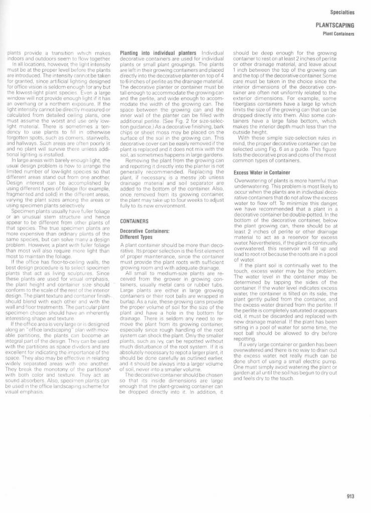
Specialties
PLANTSCAPING
Plant Containers
,ants provide a transition which makesdoors and outdoors seem to flow togetherIn all locations, however, the light intensity
must be at the proper level before the plantsare introduced . The intensity cannot be taken'or granted, since artificial lighting designed'or office vision is seldom enough for any butthe lowest-light plant species. Even a largewindow will not provide enough light if it hasan overhang or a northern exposure . If theight intensity cannot be directly measured orcalculated from detailed ceiling plans, onemust assume the worst and use only low-ght material . There is sometimes a ten-dency to use plants to fill in otherwiseforgotten spots, such as corners, stairwells,and hallways . Such areas are often poorly litand no plant will survive there unless addi-tional lighting is installed .
In large areas with barely enough light, theusual design problem is how to arrange thelimited number of low-light species so thatdifferent areas stand out from one another.Design interest can be accomplished byusing different types of foliage (for example,fragmented and solid) in the different areas,varying the plant sizes among the areas orusing specimen plants selectively.Specimen plants usually have fuller foliage
or an unusual stem structure and henceappear to be different from other plants ofthat species. The true specimen plants aremore expensive than ordinary plants of thesame species, but can solve many a designproblem. However, a plant with fuller foliagethan most will also require more light thanmost to maintain the foliage .
If the office has floor-to-ceiling walls, thebest design procedure is to select specimenplants that act as living sculptures . Sincethese plants are used for visual emphasis,the plant height and container size shouldconform to the scale of the rest of the interiordesign . The plant texture and container finishshould blend with each other and with thewall and floor treatments . The particular plantspecimen chosen should have an inherentlyinteresting shape and texture
If the office area is very large or is designedalong an "office landscaping" plan with mov-able partitions, the plants can become anintegral part of the design . They can be usedwith the partitions as space dividers and areexcellent for indicating the importance of thespace. They also maybe effective in relatingwidely separated areas with one another.They break the monotony of the partitionswith both color and texture They act assound absorbers . Also, specimen plants canbe used in the office landscaping scheme forvisual emphasis .
Planting into individual planters Individualdecorative containers are used for individualplants or small plant groupings . The plantsare left in theirgrowing containersand placeddirectly into the decorative planter on top of 4to 6 inches of perlite as the drainage material .The decorative planter or container must betall enough to accommodate the growing canand the perlite, and wide enough to accom-modate the width of the growing can. Thespace between the growing can and theinner wall of the planter can be filled withadditional perlite . (See Fig. 2 for size-selec-tion guidance .) As a decorative finishing, barkchips or sheet moss may be placed on thesurface of the soil in the growing can . Thisdecorative cover can be easily removed if theplant is replaced and it does not mix with thesoil, as sometimes happens in large gardens.Removing the plant from the growing can
and repotting it directly into the planter is notgenerally recommended . Replacing theplant, if necessary, is a messy job unlessdrainage material and soil separator areadded to the bottom of the container. Also,once removed from its growing container,the plant maytake up to four weeks to adjustfully to its new environment.
CONTAINERS
Decorative Containers:Different Types
A plant container should be more than deco-rative . Its proper selection is the firstelementof proper maintenance, since the containermust provide the plant roots with sufficientgrowing room and with adequate drainage .
All small to medium-size plants are re-ceived from the grower in growing con-tainers, usually metal cans or rubber tubs .Large plants are either in large growingcontainers or their root balls are wrapped inburlap . As a rule, these growing cans providethe proper volume of soil for the size of theplant and have a hole in the bottom fordrainage . There is seldom any need to re-move the plant from its growing container,especially since rough handling of the rootsystem can shock the plant. Only the smallerplants, such as ivy, can be repotted withoutmuch disturbance of the root system . If it isabsolutely necessary to repot a larger plant, itshould be done carefully as outlined earlier,and it should be always into a larger volumeof soil, never into a smaller volume .The decorative container should be chosen
so that its inside dimensions are largeenough that the plant-growing container canbe dropped directly into it . In addition, it
should be deep enough for the growingcontainer to rest on at least 2 inches of perliteor other drainage material, and leave about1 inch between the top of the growing canand the top of the decorative container Somecare must be taken in the choice since theinterior dimensions of the decorative con-tainer are often not uniformly related to theexterior dimensions . For example, somefiberglass containers have a large lip whichlimits the size of the growing can that can bedropped directly into them . Also some con-tainers have a large false bottom, whichmakes the interior depth much less than theoutside height .
With these simple size-selection rules inmind, the proper decorative container can beselected using Fig. 6 as a guide. This figurelists the decorative pros and cons of the mostcommon types of containers .
Excess Water in Container
Overwatering of plants is more harmful thanunderwatering. This problem is most likely tooccur when the plants are in individual deco-rative containers that do not allow the excesswater to flow off. To minimize this danger,we have recommended that a plant in adecorative container be double-potted . In thebottom of the decorative container, belowthe plant growing can, there should be atleast 2 inches of perlite or other drainagematerial to act as a reservoir for excesswater Nevertheless, if the plant is continuallyoverwatered, this reservoir will fill up andlead to root rot because the roots are in a poolof water
If the plant soil is continually wet to thetouch, excess water may be the problem.The water level in the container may bedetermined by tapping the sides of thecontainer If the water level indicates excesswater, the container is tilted on its side, theplant gently pulled from the container, andthe excess water drained from the perlite . Ifthe perlite is completely saturated orappearsold, it must be discarded and replaced withnewdrainage material . If the plant has beensitting in a pool of water for some time, theroot ball should be allowed to dry beforerepotting .
If a very large container or garden has beenoverwatered and there is no way to drain outthe excess water, not really much can bedone short of using a small electric pump .One must simply avoid watering the plant orgarden at all until the soil has begun to dry outand feels dry to the touch.

Automatic Watering DevicesIn areas where regular maintenance wouldbe difficult, the use of automatic wateringdevices can be of considerable help. Evenwhen theyare used, however, the plant mustbe checked periodically to seethat the deviceis working properly, that its water reservoir isfull, and that no other maintenance problemshave developed .Automatic watering devices are either ex-
ternal to the container or are built into theplanter. The external devices tend to workwell only with small plants, and also, they arelikely to detract from the design . For thesereasons, the built-in type of device is pre-ferred . The planters with this type come inboth cylindrical and rectangular shapes and inseveral colors . The planter has a hollowspace within its double-wall sides whichserves to hold a three- to four-week watersupply, feeding the water to the plant soil by awick mechanism, sensor, or capillary action .Most types have a float to indicate theamount of water remaining in the reservoir.
Since the soil must be in contact with thewick or capillary tubes for the device to work,the plant must be removed from its originalgrowing can and repotted directly in theplanter. As the soil never dries out, the plantmust be watched for symptoms of over-watering . Because different plants usewaterat different rates under different humidityand temperature conditions, a timetableshould be kept for each container so themaintenance staff will know when to refilleach reservoir.The use of automatic watering devices will
not eliminate maintenance personnel, but itwill reduce the number of workers needed .One person can handle many more plants,devoting more time to cleaning and trim-ming, since the reservoir has to be refilledonly every month or so . Occasionally, how-ever, one will find a client who will resist theuse of the automatic devices because he orshe likes the assurance of seeing a personwith a watering can once a week .The use ofthe automatic watering devices
is expected to increase in the future as morearchitects and designers become aware ofthem and convince their clients of theirusefulness, and as the manufacturers pro-duce more colors and styles and improve theefficiency of the devices .
Specialties
PLANTSCAPING
Plant Containers
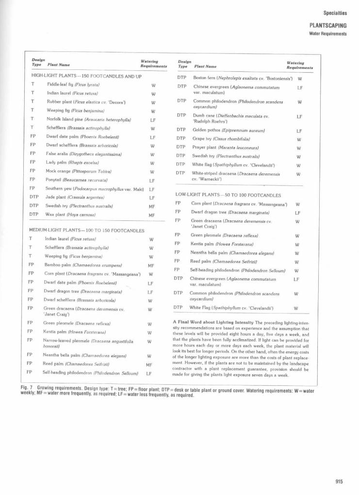
Specialties
PLANTSCAPINGWater Requirements

Specialties
PLANTSCAPING
Typical Plants
(False) Aralia
A plant of grace and elegance with narrow,ribbonlike, notched leaves of dark green,usually born on slender, single stems. Thearalia is attractive if two or three plants areplanted together in one pot. It grows veryquickly, so prune the stem tips from time totime to prevent the foliage from thinning atthe bottom .
Temperature The aralia is tolerant of warmtemperatures if there is plenty of humidity.
Light/sun The plant likes a semisunny tosemishady window ; an east or west windowis ideal.
Water/humidity
Keep the soil damp but notsoggy. The false aralia likes a humid atmo-sphere . Place your plant on a pebble tray anCmist the foliage daily.
Soil The soil should be equal parts loa-sand, and peat moss .
Special care You can rejuvenate legç .plants by drastically cutting the stems back -four to six inches from the pot. Do this in thespring and leave the plant in a sheltereclocation, being sure to fertilize and waterfrequently.
African Violet
The African violet, a longtime favorite house-plant, does insist on more care and attention,but its beautiful blossoms make the effortworthwhile .
Temperature African violets are more con-tented and grow best within a temperaturerange of 65 to 80 degrees. Be careful thatyour plants are not in an open window or adraft .
LighVsun
TheAfrican violet enjoys a place inan east or west window. Direct sun is toostrong, unless filtered through a curtain .Excess sun will cause spotting and loss ofcolor, and too little light causes elongatedstems and no blooms .
Asparagus Fern - Emerald Feather
The bright feathery green of this delightfulplant is best displayed in a hanging container.The long branches drape gracefully and arestudded with tiny white flowers that ripeninto red-orange berries .
PTemperature Asparagusabout temperatures, but60 to 68 degrees.
fern is not fussyprefers a range of
Light/sun
The bright filtered sun of an eastor west window is a good location for thisplant.
Water/humidity African violets should bewatered from the saucer underneath in themorning with lukewarm water. Water whenthe soil begins to dry out. Do not keep itsoggy. If the air is dry in your home, place thepotted plant in a tray of moistened pebbles .
Soil The soil should be porous for gooddrainage and should contain ample organicmatter such as compost or peat moss .Commercial African violet soil mixture isspecially prepared for these plants ; however,add sand or perlite to ensure adequatedrainage . A plastic pot is less likely to causethe lower leaves to rot where they touchthe pot.
Water/humidity
Soak the soil in the pot thor-oughly and allow it to become dry to thetouch before rewatering .
Soil
Awell-drained potting soil or a mixtureof equal parts of loam, peat moss, and sandor perlite .
How to start new plants
Allow the berries toripen and when dry sow the seeds theycontain. Asparagus fern can usually be grownfrom seed quite well .
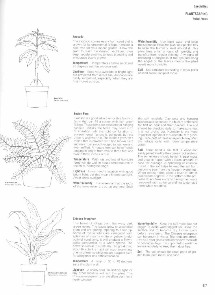
Specialties
PLANTSCAPINGTypical Plants
AvocadoThe avocado comes easily from seed and isgrown for its ornamental foliage . It makes anice tree for your indoor garden . Allow theplant to reach the desired height and thenbegin regular pinching to force branching andencourage bushy growth .
Temperature
Temperatures between 60 and70 degrees suit the avocado well .
Light/sun
Keep your avocado in bright lightbut protected from direct sun . Avocados areeasily sunburned, especially when they arefirst moved outside.
Water/humidity Use tepid water and keepthe soil moist. Place the plant on a pebble trayto raise the humidity level around it . Thisplant likes a fair amount of humidity andbenefits from regular misting . Any signs ofbrowning or crispness at the tips and alongthe edges of the leaves means the plantneeds more humidity.
Soil
Use a mixture consisting of equal partsof sand, loam, and peat moss .
Boston FernExaltant is a good adjective for this family offerns that can fill a corner with rich greenfoliage . These ferns are excellent for hangingbaskets Initially the ferns may need a lotof attention until the right combination ofenvironmental factors is achieved, but theeffort is well worth it . The leaflets grow on amidrib that is covered with fine brown hairsand vary from smooth-edged to feathery andeven ruffled . A mature fern can have frondsranging in length from two to three feet andtwo to three inches across .
Temperature
With lots and lots of humidity,ferns will do well in house temperatures inthe 60 to 70 degree range.
Light/sun Ferns need a location with goodbright light, but this means filtered sunlight .Avoid direct sunlight.
Water/humidity
It is essential that the rootsof the ferns never dry out at any time . Soak
the soil regularly. Clay pots and hangingbaskets can be soaked in a bucket or the sinkfor half an hour and then drained. The soilshould be checked daily to make sure thatit is not drying out. Humidity is the mostimportant ingredient to successful fern grow-ing . Place pots of ferns on a pebble tray. Mistthe foliage daily with room temperaturewater.
Soil Ferns need a soil that is loose andeasily penetrated by their dense root system .The soil mixture should be rich in peat mossand organic matter with a liberal amount ofsand for drainage . A sprinkling of charcoalmixed in the soil helps to keep the soil frombecoming sour from the frequent waterings .When potting ferns, place a layer of bits ofbroken pots or gravel in the bottom of the pot.Ferns do not take kindly to having their rootstampered with, so be careful not to damagethem when repotting .
Chinese Evergreen
This beautiful foliage plant has waxy darkgreen leaves . The leaves grow on a canelikestem and are oblong, tapering to a thin tip .Some of the varieties are variegated withsplashes of creamy white or yellow. Underoptimal conditions, it will produce a flowerspike surrounded by a white spathe . Theflower is similar to a calla lilly The great thingabout this plant is that it will adapt to a varietyof environments which makes it a good plantfor a beginner or a difficult location .
Temperature A range of 60 to 70 degreessuits this plant well .
Light/sun
Ashady spot, an artificial light, orany other location will suit this plant. TheChinese evergreen is an excellent plant for anorth window.
Water/humidity
Keep the soil moist but notsoggy. To avoid waterlogged soil, allow thesurface soil to become dry to the touchbefore rewatering . The Chinese evergreencan be grown in water. The roots are attrac-tive sea clear glass container showsthem offto best advantage. It is important towash theleaves regularly to keep them dust free .
Soil
The soil should be equal parts of gar-den loam, peat moss, and sand .
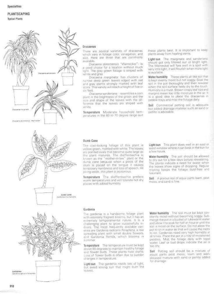
Specialties
PLANTSCAPINGTypical Plants
Dracaenas
There are several varieties of dracaenaswhich vary in foliage color, variegation, andsize . Here are three that are commonlyavailable .
Dracaena deremensis "Warneckei": isa good choice for a location without muchlight . The gray green foliage is striped withwhite and gray.
Dracaena marginata: has clusters ofnarrow deep green leaves edged with redand gray stems strongly marked with leafscars. This variety wil I reach a height of five orsix feet.
Dracaena sanderiana : resembles a cornplant in the brightness of the green and thesize and shape of the leaves with the difference that the leaves are striped withwhite.
Temperature Moderate household tem-peratures in the 60 to 70 degree range suit
these plants best . It is important to keelplants away from heating vents.
Light/sun The marginata and sandenanashould get only filtered sun or bright IgrzThe Warneckei will fare well in a spotvery little light ; it will flourish when more erris available .
Water/humidity
These plants all like soil theis kept evenly moist but not soggy Soak tr*soil in the pot thoroughly and then rewaterwhen the soil surface feels dry to the tout .Humidity is a must . Brown crispy leaf tips an:margins mean too little moisture in the a, r ris a good idea to place the dracaenas rpebble trays and mist the foliage daily.
Sail Commercial potting soil is adequatebut added drainage material such as sand xperlite is advisable.
Dumb Cane
The cool-looking foliage of this plant isyellow-green, mottled with white. The leavesare pointed ovals that become quite large asthe plant matures . The dieffenbachia isknown as the "mother-in-law" plant or thedumb cane because when a piece of thestem is placed on the tongue it causestemporary numbness and loss of speech . Alljoking aside, this plant is poisonous.
Temperature The dieffenbachia preferswarm temperatures and will tolerate hot dryplaces with added humidity.
Light/sun
This plant does well in an east c~west window where it can bask in the sun fc -a few hours.
Water/humidity The soil should be allowe--to dry out for a few days before rewaterinçThe plants indicate a need for water whe^the leaves show signs of dropping . Regulwmisting keeps the foliage dust-free andluxuriant .
Soil
Aporous soil of equal parts loam, peatmoss, and sand is fine .
Gardenia
The gardenia is a handsome foliage plantwith intensely fragrant blooms, but it has anextremely temperamental nature . It is achallenging plant to grow successfully in-doors. The most frequently available vari-eties are Gardenia radicans floraplena, a lowspreading plant with small double flowers,and Gardenia florida, which blooms insummer.
Temperature
Thetemperature must be keptabove 65 degrees to maintain healthy foliageand flower buds . These plants hate drafts .Loss of flower buds is often due to suddenchanges in temperature .
Light/sun The gardenia needs lots of light,but avoid strong sun that might burn theleaves .
Water/humidity The soil must be kept con-stantly moist without becoming soggy. Sub-merge the pot in a bucket of lukewarm waterand allow it to soak for half an hour or until thesoil is moist on the surface. Do not allow thepot to sit in water as that will cause the rootsto rot . Gardenias need very high humidity atall times. Place the pot in a tray of moistenedpebbles . Mist the foliage daily with tepidwater. Leaf or bud drops indicate the air istoo dry.
Soil Potting soil should be a mixture ofequal parts peat moss, loam and well-decayed manure with sand or perlite addedfor drainage .

Specialties
PLANTSCAPING
typical Plants
Grape Ivy
Grape ivy is a climber or trailer The olivecolored green leaves look a bit like those ofholly without the stiffness or the sharp tips .The leaves form attractive groups of threeand are accompanied by furry tendrils .
Temperature
The plant is fairly tolerant of awide temperature range. Increase theamount of humidity as the temperaturegoes up.
Light/sun Grape ivy will do all right in lowlight and is often used in low light areas. But itflourishes with bright light orfiltered sunlight .
Water/humidity Soak the pot and soil thor-oughly and then allow the soil to become dryto the touch before rewatering . Mist fre-quently and wash the foliage regularly toremove dust and restore the luster of theleaves .
Soil A potting soil that is rich in organicmatter is the best . Be sure to add plenty ofdrainage material to the soil mixture.
Jade PlantThe jade plant is a tough plant well-suited tothe hot dry conditions so prevalent in officeand apartment buildings. The rounded leavesare in pairs on the branched treelike stem . Aplant that is six to eight years old will produceclusters of lacy-looking star-shaped flowers.
Temperature
Temperatures ranging from 65to 75 degrees are fine . Lower and highertemperature will be tolerated .
Light/sun The jade plant will require fullsunlight with shade at midday if possible . Awest or south window would be good loca-tions . If you put the plant outside in thesummer, place it in a lightly shaded spot .
Water/humidity The soil should remain dryfor several days between waterings. Thefleshy leaves soak up the soil waterand storeit for future use. Too much water will causestem and root rot and certain death.
Soil
Thejade plant will do well in rich gardensoil that has coarse sand or fine bits of brokenpots added to it for drainage . Each year givethe pot a top dressing of humus . A new potwill be necessary only after about three orfour years .
Norfolk Island PineThe delightful symmetry of this evergreenmakes it a desirable house plant. Thebranches grow in tiers of six, each tierrepresenting a year's growth . The brightgreen needles are soft and pleasant to touch.
Temperature The ideal temperature is be-tween 50 and 60 degrees . High tem-peratures are tolerated when sufficient hu-midity is available .
Light/sun
Thefiltered sun of an east or westwindow is best . Yellowing of the needlesmight mean too much sun .
Water/humidity Provide the plant with awell-drained soil and pot. Water thoroughlyand allow the soil surface to become drybefore rewatering . Daily misting is necessaryforthe warmer temperatures of most housesand offices . A pebble tray will help to addmore moisture to the air around the plant.
Soil
Garden loam mixed with equal parts ofsand and peat moss makes a suitable pottingmixture. Repot the Norfolk Island pine onlywhen it has become potbound (the pot iscrammed with roots( . This would be aboutevery two or three years.

Specialties
PLANTSCAPINGTypical Plants
Parlor Palm
The palm trees are not the easiest plants togrow. However, once you have discoveredtheir basic needs they are a delightful addi-tion to your indoor garden . This palm growsto about four feet tall . It is most attractivewhen two or three plants are grouped to-gether in a pot. The long feathery frondsgrow out of a single stem . Other varieties totry are C. seifrizii, C. erumpens, and C.costarincana .
Temperature The best growing tem-peratures for palms range between 60 and75 degrees.
Light/sun Palms are good plants for loca-tions without much light . They do not likedirect sun light .
Water/humidity During the active growingseason, between March and October, thepalm needs moist soil but it will not toleratesoggy soil . In the winter months, allow thesoil to dry on the surface before rewatering .If the foliage shows signs of browning anddrying on the tips, it needs more humidity.Misting regularly is recommended to keepthe foliage healthy.
Soil The palm needs well-drained soil ofequal parts rich garden loam, peat moss, andsand . It will need repotting only every two orthree years. It prefers being a bit potbound .
PhilodendronBy nature, the philodendron is a climbingplant, but it also trails . It looks best on abracket beside the window frame, and forgood effect must be kept strongly pinchedback so that the plant is full of bushy younggrowth and does not deteriorate into two orthree stringlike stems.
Temperature Normal house or office tem-peratures are fine .
Light/sun The philodendron is quite hardyand robust and will grow almost anywhere .However, it will fare better in a well-lightedarea .
Water/humidity The plant should be keptevenly moist and never allowed to dry out.Be certain water does not remain in thesaucer after watering . The foliage should bemisted daily and the leaves cleaned of accu-mulated dust
Sail Potting soil mixed with perlite, ver-miculite, or sand and peat moss isrecommended .
Windowleat Philodendrom
This philodendron has large heart-shapedleaves that are slashed irregularly. It is anenthusiastic climber and needs a piece ofbark ortotem for support. The aerial roots canbe inserted in the soil or encouraged toattach to the totem. Keep the growing tipspinched back so that the plant doesn't getleggy.
Temperature The windowleaf prefers tem-peratures between 65 and 70 degrees.
LighUsun
Bright light is best for this plant.However, avoid putting the plant in a locationwhere the plant would get direct sun .
Water/humidity Soak the plant thoroughlyand allow the soil surface to remain dry for aday or two before rewatering . Mist thefoliage daily and wash the leaves weekly toremove dust .
Soil A soil mixture of equal parts gardenloam, peat moss, and sand is fine .

Specialties
PLANTSCAPINGTypical Plants
Purple Passion Plant-Velvet PlantThe strikingly rich royal purple coloring and
" velvety texture of the foliage and stemsattract many growers. The green leaves andstems are covered with tiny purple hairs. Thestraggly growth habit is best kept in check byfrequent prunning .
Temperature The purple passion plant likestemperatures in the 65 to 70 degree range.
LighUsun
Direct or partial sun will promotethe color.
Water/humidity
It is important that the vel-vet plant not dry out. Keep the soil evenlymoist at all times. A humid atmosphere isimportant to keep the brilliant color. Mist thefoliage frequently and place the pot in a trayof moistened pebbles to raise the humidity.
Soil
Use potting soil of equal parts gardenloam, peat moss, and sand . This plant willalso grow in water.
Rubber Tree Plant
This house plant with dark green glossyleaves can grow to be four feet high with alittle care and not too much water.
Temperature Due to its hardy nature, theplant does well in any normal householdtemperature .
LighUsun The plant will do well in almostany light, buta well-lighted area is best for therich green foliage characteristic of the rubbertree plant.
Water/humidity
Water only when the soil iscompletely dry all through the pot. Youshould set the entire pot in a bucket when
watering, so that moisture can penetrate thedeepest roots . Clean the leaves every twoweeks or so with a damp cloth . Do notartificially shine the leaves as this clogs theplant's pores and does not allow it to breathe!
Soil
Soil should be a well-drained mixture ofequal parts of sand, peat moss, and gardenloam . If pot is plastic or rubber, be sure toprovide plenty of drainage material in thebottom of the pot.
Wandering JewThis is a particularly attractive hanging plant.It is hardy and easy to grow with only onespecial requirement, which is regular pinch-ing to keep it full and bushy. There are severalplants called Wandering Jew, distinguishedfrom each other by their different coloringsand markings . The illustration is a Zebrinapendula. The leaf is a pointed oval with adeep purple underside, and the upperside isdark green striped with pale silvery-green .Tradescantia flurninensis has small ovalgreen leaves marked with white, silver andwhite, or yellow.
Temperature These plantstemperatures .
prefer warm
LighUsun
Bright indirect sunlight keeps thefoliage brilliant . Avoid direct sunlight as theyare susceptible to sunburn .
Water/humidity Water generously, keepingthe soil moist at all times. During the wintermonths it will not need quite as much water
Soil
This plant grows in a well-drained pot-ting soil, or water.

Specialties
PLANTSCAPINGTypicat Plants
Schefllera -Umbrella TreeIf you are looking for a tree for your indoorgarden, a schefflera is a good choice . It hashandsome deep green leaves that radiate outfrom a long slender stalk rather like the ribs ofan umbrella .
Temperature
The umbrella tree does well ina room where the temperature ranges from55 to 75 degrees.
Light/sun
The schefflera does not like directsunlight . It grows best in good light from ashaded window.
Water/humidity
When watering your schef-flera, soak the pot thoroughly and then allowthe soil to dry before rewatering . The plantlikes a humid atmosphere and responds wellto daily misting with warm water. This isessential if the plant is in a room with forcedhot air heat . This plant needs a pebble tray.
Soil
The soil mixture for the umbrella treeshould be equal parts of peat moss, gardensoil, and sand . The pot should have a layer ofgravel or bits of broken pots underneath thesoil to ensure good drainage .
Snake PlantSeen in many homes and offices, this spikeybanded plant will take almost any abuse.
Temperature Normal household tempera-tures are best, but do not allow the plant tobecome suddenly chilled!
Light/sun
Thesnake plant is a good low lightplant but needs sun in order to bloom
Water The plant likes the dryness of thehome and should never be overwatered. Theleaves should be cleaned with clear waterevery two weeks.
Soil Garden loam, peat moss, and sandmixed together provides the best soil for thesnake plant.
Spider Plant
With its green and white foliage, the spiderplant makesone of the best hanging plants .The graceful trailing runners have plantletsand white star-shaped flowers. There are all-green varieties but the more commonly seenone has a green leaf striped with white.
Temperature
The plant lives best in a warmlocation .
Light/sun This lovely plant does very wellhanging in indirect sun or a moderatelylighted area .
Water/humidity The spider plant should beallowed to dry out before rewatering . Dryingleaf tips usually indicates lack of humidity. Totidy up the plant just snip these off.
Soil
The plant grows contentedly in a richsoil composed of garden loam, sand, andpeat moss .
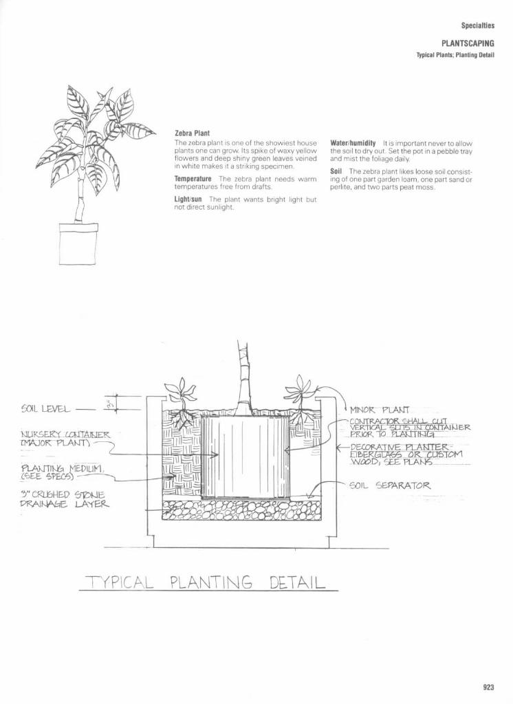
Specialties
PLANTSCAPING
Typical Plants ; Planting Detail
Zebra PlantThe zebra plant is one of the showiest houseplants one can grow. Its spike of waxy yellowflowers and deep shiny green leaves veinedin white makes it a striking specimen .
Temperature The zebra plant needs warmtemperatures free from drafts .
Light/sun The plant wants bright light butnot direct sunlight .
Water/humidity
It is important never to allowthe soil to dry out. Set the pot in a pebble trayand mist the foliage daily.
Soil
Thezebra plant likes loose soil consist-ing of one part garden loam, one part sand orperlite, and two parts peat moss .
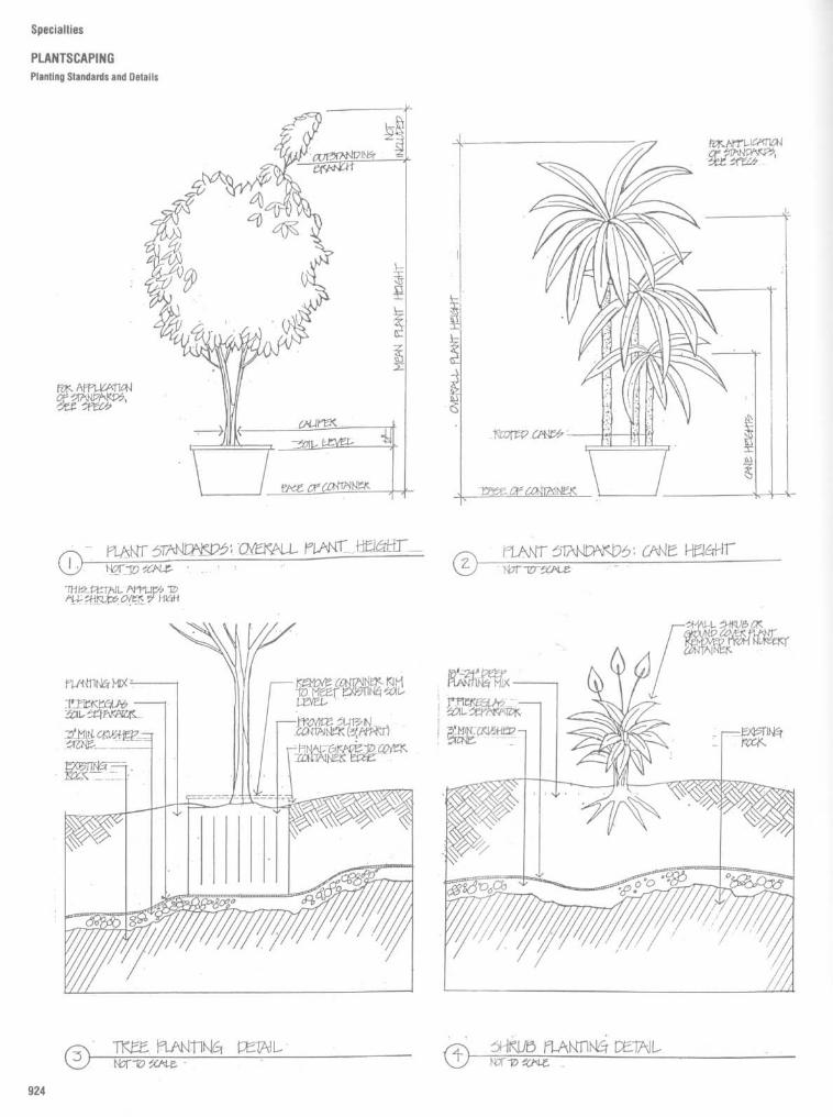
Specialties
PLANTSCAPINGPlanting Standards and Details

Specialties
PLANTSCAPINGPlant Containers

Specialties
PLANTSCAPINGPlant Containers

Fig . 8
Detail 1 : In this window planter, the plants are placed directly in the earth or growing medium filling the planter and continueto grow and blossom there . The entire planter is contained within a galvanized steel pan with drain . The 6-in-high perforated pipeallows for drainage of excess water overa long period of time before the entire planter has to be cleaned out and startedanew. Detail2 : This is a simple floor-level planter where the drainage can easily be connected to the building's drainage system . Here also, plantsare installed and grow naturally until a complete planting change is required . Detail 3 : A room divider planter for the Ackermannresidence, Southampton, New York, consists of a planter-bookcase combination . Here the plants remain in their clay pots and areinserted in the planter with orwithout gravel orsome other type of filler. The entire planter is pitched toward oneend, where the drainempties into a small container which catches any extra water.
Specialties
PLANTSCAPINGPlant Containers

SpecidltieS
PLANTSCAPINGPlanters
Planter for a restaurant or store
Fig . 9
Detail 1 : The plants remain in their own clay pots . The use of pea gravel at top and only 4 in of 3/4-in gravel at bottom permits easy
changes of the plants . To take care of watering and drainage, the copper pan is simply sloped to one side and two screened drains are connected,
trapped, and joined to a waste line . This takes care of any excess water, as it is eliminated by gravity drainage . Detail 2 : This planter is for areas
where freezing does not occur, and the drainage of excess water can be taken care of by simply extending small pipes directly to the exterior.
Detail 3 : In this planter the plants remain within the planter and excess water is carried off by a screened pipe at the bottom . Pea gravel is used as
a 1-in topping so that odds and ends drooped into the planter can easily be removed . Detail 4 : A planter in a commercial lobby or entrance is
shown in this detail . The plants are permanently installed and the tall drainage pipe takes care of any top applied water. The white sand at the top
is to bring contrast to the colors of the plants .

Specialties
PLANTSCAPINGBenches

Specialties
PLANTSCAPING
Benches

Specialties
SIGNAGE AND GRAPHICSSignage System Design Criteria
SIGNAGE SYSTEM DESIGN CRITERIAInitial consideration should be directed to-ward determining the basic parameters re-quired in developing the sign system Each ofthem merits discussion here .
Perlormance RequirementsSigns usually must be designed to meetspecific performance requirements . Thegood designer will determine how a systemis to perform within given space rela-tionships . The sign system may functionentirely on its own merit, or it may besupplemented by staff personnel at majordecision-making locations, such as the mainlobby and reception areas . Sign devices maybecome decorative amenities to be featuredwithin the environment, or they may besubtle and low-key elements of minor impor-tance . Supergraphics may be considered incertain areas simply as an art form, or as afunctional graphic device presented in largescale for emphasis of context . Certainly, acombination of the two is feasible . These areonly several performance considerations thatshould be addressed prior to the develop-ment of the signage system . The designermust evaluate the needs of the client, theunique traffic flow requirements and mount-ing restrictions dictated by the structure, andthe basic performance requirements desiredof the signing devices to be utilized .
Usage ConsiderationsThe general nature of the building complexoften defines how signs are to be used . Theymay be given an appearance of being fixedand an integral part of the architecture by theappropriate selection of materials, colors,and mountings, or they may appear change-able and temporary should need so dictate .Some signage requires constant change toproperly relate information to people or peo-ple to facility, while most sign devices areconsidered permanent fixtures within agivenspace . The designer is responsible for deter-mining how signs are to be used mosteffectively, and at the same time, for enhanc-ing the environment .
Durability RequirementsPrior to the selection of materials for asigning system, durability requirementsmust be considered . The vast assortment ofmaterials available for signs covers a widespectrum of durability from soft plastics tometals . The sign copy and backgroundmaterial should be evaluated both indi-vidually and jointly when considering du-rability requirements .
Vandalism ConsiderationsSigns located in controlled spaces are oftenfree from destructive vandalism, however, inmany instances vandalism becomes ram-pant and uncontrolled . There are no materialsthat may accurately be labeled "vandal-proof ." However, some materials are more
Helvetica MediumClarendonFin_ t
vandal-resistant than others . Where van-dalism is of prime importance, only materialsand graphic techniques engineered to resistdestruction should be considered .
Flexibility to Accommodate Changesand AdditionsModern architectural structures are de-signed to accommodate inner spacialchanges to meet tenant needs . Partitionsystems, prehung door units, room dividers,and modular furniture have ensured ease ofchange in officescapes . The sign systemmay also require alterations to preservecontinuity. Changes and additions to a signsystem should be considered by the de-signer prior to the selection of materials,graphic techniques, and mounting methodsto be used .
Readability FactorsSign readability is determined by the letterstyle selected, size of copy, interletter spac-ing, copy position relevant to background,colors, and angle of observance .
Letter style Letter styles are classified assanserif and serif. Sanserif letters, such asHelvetica, are more contemporary than serifletters, such as Clarendon (Fig . 1). Each letterstyle has its own unique personality andflavor. Printers carry alphabets in most letterstyles, including lowercase letters as well asuppercase (Fig . 2). Test results indicate thatmessages starting with an initial uppercaseletter and followed by lowercase charactersare more recognizable than messagesformed with uppercase characters only.Lowercase letters have more "personality"because their shape is varied by ascendersand descenders, resulting in characteristicword forms that are much easierto recognizethan all-uppercase word forms . Also, peopleare more accustomed to reading text inupper- and lowercase than in all uppercase .The proper selection of a particular alphabetshould be carefully considered, not only froma legibility point of view, but also from a"personality" standpoint . The letter styleshould make a concise and meaningful im-pression in the environment it serves .Readability
Readability is directly related tothe size of copy. Visibility studies indicate that1-inch-high Helvetica Medium, for example,is readable from a distance of 40 feet . Usingthis as a measure for comparison, 1-inch-highClarendon style would be readable from asomewhat lesser distance, approximately 25feet . The distance visibility per 1-inch heightmay be used as a guideline to determinedistance readability for larger letters ; that is,2-inch-high Helvetica Medium will be read-able at 80 feet, and 3-inch-high at 120 feet .This direct proportion may be helpful fordetermining copy (text) sizes for signs usedin pedestrian situations . However, the directproportion may not hold true for vehiculartraffic applications where many other factorsare involved . The designer must exercise
HELVETICA MEDIUMCLARENDONFin_ 2
caution after selecting the alphabet and copysize to make certain the lettering will fitproperly on the sign background . The signsize should be determined using the longestline of copy and the maximum number ofcopy lines that may be required .
Letters and line spacing Interletter spacingand interline spacing of copy greatly affectthe overall readability of a sign. Messagelegibility and ease of recognition are in-creased when proper visual relationships areestablished between individual characters,words, and lines of copy. Copy with spacingtoo tight becomes very difficult to read ; copywith too open spacing tends to break themessage down into fragments (Fig . 3) .Proper spacing depends largely on the dis-tance from which the message is to be read .Messages to be read at close distancesshould employ tighter spacing than mes-sages that will be read at greater distances .Spacing is also affected bythe angle atwhichthe message is to be viewed : Greater anglesof observance require wider interletter spac-ing to prevent the characters of the messagefrom appearing to run together.
Copy position The position of copy on thesign background influences the overall read-ability. Signs on which copy occupies most ofthe background are not as readable as signsthat have sufficient background material sur-rounding the copy to form a visual barrierseparating the message from the environ-ment (Fig . 4 and 5) .Emphasis should be placed on selecting an
appropriate sign size to best accommodatethe sign message. There are nine basic copyplacement positions to be considered indetermining the important relationship ofcopy to sign background . They are : upperleft, upper centered, upper right, centeredleft, centered, centered right, lower left,lower centered, and lower right . Traditionally,the most popular placement selections havebeen the centered and upper left positions .Color Color of copy and sign backgroundgreatly affect readability. Strong contrastingcolors are more readable than less dramaticcolor combinations . White copy on a blackbackground offers the greatest contrast andreadability Color alsoinfluencestheapparentrelationship between the copy size and thebackground . For example, white copy on ablack field appears larger than blackcopyon awhite field, although letter height, size, andcopy position remain the same in both exam-ples (Fig . 6) .
Colors in a signage system should alsorelate harmoniously with the pallet of colorsselected for the building and its environment .The designer may choose to select colorsthat blend with the environment or vibrantprimary colors that accent the sign systemand perhaps contrast with the architecturalcolor scheme .
Ardiitectual Signage SystemsArchitectural Signage SystemsFin . 3

Specialties
SIGNAGE AND GRAPHICS
Signage System Design Criteria
32
The viewing angle
The angle of observanceis influential in the design of a signagesystem, since it affects interletter spacingand overall readability. Normally, interior signsare viewed chiefly from a straight-on posi-tion, however, exterior signs are frequentlyseen from more than one angle. Signs to beread from vehicles moving at varying speedswith different angles of observance mayrequire a compromise in letter spacing tobest communicate the message.
Multilingual Needs
The jet age is a contributing factor in bringingpeople together from all over the world tovisit and transact business . Transportationterminals and public facilities that may beused by visitors unaccustomed to readingEnglish should employ sign systems thatbridge any visual communication gap. Multi-lingual messages in English and the domi-nant foreign languages used by visitors maybe combined and presented on one signbackground . However, sign design andgraphic formats become very critical to pre-vent confusion . A more popular solutioninvolves the use of pictorial symbols as wordsubstitutes . Pictographic signs are bold, rec-ognizable images not bound by languagebarriers .
Regulatory Considerations
The designer should become aware of reg-ulations governing signs. Federal regulationsconcerning safety signs are enumerated inOccupational Safety and Health Administra-tion (OSHA) publications . American NationalStandards Institute (ANSI) publishes stan-dards concerning signage for the physicallyhandicapped . Underwriters' Laboratory (UL)issues standards applicable to illuminatedsigns . State and local codes contain reg-ulatory information concerning sign sizes,mounting locations and heights, quantities of
signs allowable in various zoning areas, andother restrictions relating to exterior signs .These rules, and those of other regulatorybodies, should be taken under advisementpriorto completing a comprehensive signageprogram.
Need for IlluminationMany signs are required to relate the r mes-sages after dark as well as during naturaldaylight . The careful designer will determinewhich signs require artificial illumination anddecide on the method of illumination . Signscan be externally illuminated by readily avail-able stock fixtures produced by many manu-facturers, or they can be internally illumi-nated . Fluorescent lighting is the mostcommon source of internal illumination, al-though metal arc lamps, incandescentlamps, and neon are frequently employed .
Need for a Graphics Manual
Many signage programs are developed forinstitutions that have a continuing need notonly to maintain, but also to augment orchange, their signage systems . The prepara-tion of a signage manual containing all theinformation required to create additionalsigns or components would benefit the clientand ensure continuity in the system aschanges and additions are made . The de-signer should determine this potential needand include the manual with other docu-ments developed for the signage program.
SIGN TYPES CATEGORIZEDBY FUNCTION
Signage systems should be logically brokendown into various types of signs to be utilizedon a particular project. Many categories ofsign types maybe developed, but one of themost conclusive listings is based on function .The following discussion of signage system
components, including sign requirements forspecific applications, covers these functions .
Exterior Signs
Exterior sign system components are nor-mallyviewed from vehicles or by pedestrianswho have parked their vehicles and arewalking toward their destination .
Primary identification All architectural pro-jects require some form of identification thatis both easily readable and recognizable . Aperson's first association with a building isthe identifying device selected to "label" thestructure . The importance of the first impres-sion created by this device should be recog-nized. A sign that produces an image inkeeping with the environment it serves re-flects the quality of the people associatedwith that environment. Major corporationsspend large sums of money on corporateidentity programs to ensure the visual imagepresented to the public best reflects corpo-rate philosophy and product desirability.Equal emphasis should be placed upon theimage presented by the device employed toidentify an architectural structure .
Secondary identification Many complexescontaining more than one basic structurerequire secondary identification signs toproperly identify the various elements withinthe complex. A systems approach to designwill provide continuity in the relationship ofprimary to secondary identification signs .
Vehicular advance notice A system of roadsigns suitably located in advance of decision-making points will allow vehicular traffic toexecute the proper decisions smoothly andsafely at the appropriate times.
Vehicular directional
Intersections and park-ing facility entrances are major decision-making locations requiring directionaldevices to guide drivers toward theirdestination .
Traffic regulatory and control
Vehicular trafficcan be systematically controlled by employ-ing signing devices. Traffic codes are usuallyclear as to what signs are required, wherethey are to be located, and the height atwhich they are to be mounted. Usually,colors, sizes, and shapes are standardizedby the traffic authorities . Stop, yield, andspeed limit signs are representative of thisclassification of signs.
Instructional Frequently, signs are requiredto instruct vehicular and pedestrian traffic .These notices must be properly installed incarefully selected locations to be effective.Examples include parking procedures, deliv-ery and service directions, and the like .
Informational
Signs are required to presentinformation that is both relevant to the loca-tion and important to the viewer. This infor-mation may pertain to parking rates, hours ofoperation, and security, or it may relate toitems of interest within the environment .
Decorative
Decorative graphics maybe em-ployed to enhance the beauty or decor of aparticular area, form, color, and design maybe utilized to create interest and to becomefeatures of the exterior landscape.

Specialties
SIGNAGEAND GRAPHICS
Signage System Design Criteria
Interior Signs
Interior sign system components should as-sist visitors to travel from the building en-trances throughout the complex until theyreach their desired destination .
Identification Multiple-occupancy buildingsrequire tenant identification ; frequently,buildings with only one tenant will also utilizeidentification in the main lobby or receptionareas to reinforce the corporate signature.Criteria for multiple-tenant signage are veryimportant and should be included in leasedocuments to provide for visual continuityand architectural harmony When individualsare allowed to implement their own desiresconcerning signage, each will attempt tooutdo the other, resulting in clutter, confu-sion, and visual pollution . Signs that are toobig, too gaudy, too competitive, and poorlyconceived and executed will become com-monplace unless controls on tenant identifi-cation are established and enforced .
Primary directory Information relevant toone's location within a complex should beclearly enumerated on the primary directory,usually located in a very visible area of themain lobby. Alphabetized listings of tenants,departments, and individuals should be con-cise and should designate the floor and roomnumbers . Such directories may be flush orrecessed wall mounts, horizontal projectedwall mounts, or pedestal or kiosk mounts,and internally illuminated or not, dependingupon the ambient lighting conditions .
Elevator lobby floor directory
High-rise struc-tures require well-positioned signage thatnot only identifies each individual floor, butalso serves as a secondary directory systemfor that floor. Frequently, the floor identifi-cation, directory, and corridor directionalsignage may be included in one device .When a visitor exits from an elevator on achosen floor, a sign showing the floornumber and also the direction of the office orroom number sought is both helpful andreassuring .
Pictorial "you are here" indicators Pictorialschematic maps may become an integralpart of directory systems, or they may beutilized separately as visual aids in depictingone's intended passage through a complex.Hospitals, sports complexes, and transporta-tion centers, are good examples of structurethat may require pictorial maps to supple-ment word messages . Caution will be exer-cised by the expert designer to keep thepictorial mapsimple and correctly oriented inthe building according to where the viewer isstanding, and to evaluate the need of colorcoding as part of the visual aid. Too fre-quently, designers employ a complicatedcolor-coded system that becomes very con-fusing to the viewer and, in fact, compro-mises the effectiveness of the system .
Primary directional
The maze that often re-sults from interior corridor layouts createsmany decision-making points for a visitor.Primary directional signs may be ceiling-mounted, wall-mounted, or floor-mounted askiosk-type units in open areas. Areas withheavy pedestian traffic should have direc-tional signs located so that people do notobstruct the line of sight to the sign device
Normally, ceiling-suspended or kiosk-typeunits are the best choice to enhance visibility.
Secondary directional Directional signsshould be considered in locations wheretraffic flow and corridor layouts do not de-mand primary directional devices but dorequire some guidance for direction control.Corridors within suites of offices and cor-ridors that change direction should be consid-ered as decision-making points that mayrequire a secondary directional signagedevice .
Area identification Specific areas within acomplex should be properly identified . Theseareas may be tenant spaces, divisions, ordepartments. When occurring along maincorridors, they are usually designated bywall-, door-, or transom-mounted devices.Ceiling-suspended signs are a good solutionin open office spaces .
Room identification Wall- or door-mountedroom identification signs are required to"label" the function of a particular room .Work functions are properly identified withintenant areas, while service and maintenancefunctions should be suitably designated inmost situations .
Desk identification
Reception areas may re-quire a sign device located on a desk orcounter to identify a particular service orindividual rendering assistance to visitors .Such signs may be permanently affixed orremovable, and may provide for changeablename inserts .
Personnel identification
Persons rendering aservice to the public, such as nurses, mainte-nance personnel, and food service person-nel, generally are identified by name badgesor pins .
Regulatory and control signs Signs that au-thorize or prohibit certain functions are re-quired, frequently by law or code, to informpeople using the facility. Examples includesigns for the handicapped and signs relevantto no smoking areas, elevator capacities, "noentry" areas, fire control, and "authorizedpersonnel only" areas. These signs are usu-ally mounted ondoors ortheiradjacentwalls ;they may employ colors which deviate fromthe standard colors used in the comprehen-sive signage system to emphasize a dan-gerous situation or the need for caution .
Exits Exit signs are required by codes todesignate exits effectively in times of emer-gency. Supplemental devices are used togive additional information pertaining to aparticular exit such as "Emergency ExitOnly" and "Alarm Sounds When Door IsOpened ." OSHA-approved exit signs arestandard items manufactured by many light-ing companies, and are generally provided bythe electrical contractor.
Information exhibit cases Notices, posters,attractions, and promotional pieces shouldbe contained within an appropriatelydesigned case to control the display of thistype of information . Standard units featuringvinyl-covered cork panels housed withinextruded aluminum frames with lockabledoors are available from many directorymanufacturers.
Decorative features
Decorative designs maybe reproduced on walls as interior features .Reproduction processes include appliques,painting, and screen printing on location ; ormural processes, which are applied muchlike wall-coverings, may be considered .Doors may also receive supergraphic treat-ments in which copy maybecome an integralpart of the design .
Dedicatory plaques Building dedicationplaques should be carefully conceived andimplemented, using materials that reflectfavorably upon the talents involved in therealization of the project . Historically, theseplaques have been bronze or aluminumcastings . However, modern technology hasprovided photographic methods andphotochemical processes which offerthe designer a freedom of size, format,letterform, and color not available in thecasting operation .
Donor recognition Buildings constructed inpart by contributions from donors requirespecial recognition for the donors. Hospitals,performing arts centers, and service institu-tions rely on gifts to assist in financingbuildings, additions, and furnishings, andusually stipulate that donors will be remem-bered and recognized in some prestigiouslocation in the building . The designer isresponsible for establishing controls anddeveloping a system that fulfills promisesmade by those soliciting funds, while allow-ing flexibility to expand the system as futureneeds may dictate. Location selection is veryimportant in the overall effectiveness of thedonor recognition signage.
Mechanical, instrumentation, and control sys-tem markings Many industrial and mechan-ical installations require equipment, control,and pipe markings to meet codes, assistmaintenance and service personnel, andensure safety. Often, these locations are notpublic spaces, and require an industrial,rather than an architectural, approach tosignage. Elevator floor-indicator panels,however, should receive special attentionand be considered in a comprehensive sign-age program.
CONCEPTUAL DESIGN OF THESIGN FACE
Emphasis will not be placed on the graphicdesign of each sign required in a compre-hensive signage program . However, thefollowing considerations will help to ensurecontinuity, correctness, and aestheticacceptability.
Alphabet selection An alphabet must becarefully chosen that best exemplifies thegraphic image to be portrayed to the publicwithout compromising legibility and perfor-mance requirements . More than one alpha-bet may be selected should need dictate.However, good design practices should bemaintained in choosing the family of alpha-bets to be employed .
Interletter, word, and line spacing
Each alpha-bet has its own "personality" and visualimpact ; therefore, spacing between charac-ters, words, and lines of copy must becarefully developed to give the best legibilityand visual harmony possible (Fig . 8) .

Specialties
SIGNAGE AND GRAPHICSSignage System Design Criteria
Arrow selection Directional arrows shouldbe designed to reflect the "personality" ofthe letterform selected . Stroke width andsize relationships are important considera-tions (Fig . 9) .
Copy determination The message for eachsign must be accurately determined and thecopy condensed to the fewest words thatwill still relay the desired message . Wordysigns are frequently misread or not read atall . The message must be concise, clear, andinformative (Fig . 10 and 11) .
Copy placement format The placement ofcopy on a sign face may take one of the ninebasic positions or a custom formatfor specialsituations (Fig . 12) .
Size determination of the sign face
After thecopy for each sign is in final form, the signwith the greatest amount of copy is selectedfrom each of the sign types utilized and thedesired copy height is determined for eachtype . This height should be based upon thedistance from which the sign will be read andthe graphic design portrayed . Using thisletter height, the message should be laid outwith photographic type or transfer letteringto scale, incorporating the copy placementand spacing requirements . The most pleas-ing shape and size for the message to becontained are then determined, realizing thatthis particular layout is for the maximum copyrequired for that particular sign type . A shapeand size format should be chosen that workswell as a module which can be proprotionedand become applicable to the entire family of
sign types . While this may be ideal, fre-quently the proportional system is not ap-plicable . An exampleof each sign type shouldbe drawn to scale and fully dimensioned toserve as a production guide for signs withinthat type . (Fig . 13).
Color selections
Selection is then made ofthe copy and background colors that offergood contrast and harmoniously blend withthe prominent colors in the environment .It is also wise to consider any corporatecolors required by the client .
SIGNAGE SYSTEM DEVELOPMENTCHECKLISTThe completed sign schedule, location plans,scaled drawings of typical examples fromeach sign type, construction or assemblydetails or both, mounting details, and specifi-cations form the documents required to bidcompetitively or to negotiate signage proj-ects . Well-prepared documents prevent indi-vidual interpretation by vendors and result incomparable competitive bids .The following systematic approach to the
design and development of a comprehensivesignage program will serve as a guideline toproblem solving, employing the conceptscontained in this chapter. This checklist maybe expanded or condensed to meet indi-vidual project parameters . The basic system-atic thought process, however, is applicableto all projects .
1 . Develop the signage system designcriteria based on :
a . Performance requirementsb . Usage considerationsc . Durability requirementsd . Vandalism considerationse . Flexibility to accommodate changes
and additionsf. Readability factorsg . Multilingual needsh . Regulatory considerationsi .
Need for illuminationj .
Need for graphics manual forongoing implementation and systemmaintenance
2 . Study the traffic flow patterns, deter-mine all sign locations, and draw the locationsymbols on the site and floor plans .
3 . Evaluate and select the sign types re-quired from the following list, categorized byfunction, that meet the design criteria :
a . Exterior sign types :Type A-Primary identificationType B-Secondary identificationType C -Vehicular advance noticeType D- Vehicular directionalType E -Traffic regulatory and controlType F-InstructionalType G-InformationalType H -Decorative
b . Interior sign types :Type 1-Primary identificationType J - Primary directoryType K-Elevator lobby floor
directoriesType L-Pictorial "You Are Here"
indicatorsType M -Primary directionalType N -Secondary directional

Specialties
SIGNAGE AND GRAPHICSSignage System Design Criteria
Type 0-Area identificationType P-Room identificationType Q-Desk identificationType R-Personnel identificationType S -Regulatory and controlType T- ExitType U-Information exhibit casesType W-DedicatoryType X-Donor recognitionType Y-Mechanical,
instrumentation, and controlsystem markings
Type Z-Other (to be specified bydesigner)
4 . Select the best signing devices for eachsign type designated above from the follow-ing lexicon of signage system components
that most effectively satisfy the design crite-ria established :
Elevated pylonsMonolithic sign structuresPanel and post assembliesIlluminated sign cabinetsDirectory and informational systemsDie-cut pressure-sensitive letteringDimensional graphicsPlaque signageEnvironmental graphicsOther (to be defined by the designer)
5 . Conceptually design the sign face foreach sign type selected, indicating :
a . Alphabet selectionb . Interletter, word, and line spacingc . Arrow selection
a .b .c .d .e .f .
d . Copy determinatione . Copy placement formatf .
Size determination of copy and signface
g . Color selections6 . Complete the location plans by filling in
the symbol indicating sign number and type .7 . Prepare scaled drawings of typical ex-
amples from each sign type .8 . Prepare the detailed sign schedule .9 . Prepare typical construction and assem-
blydetails, mounting details, and engineeringdrawings for wind loading, foundations, andillumination .
10 . Prepare detailed specifications for allmaterials, techniques, and components re-quired in the system .
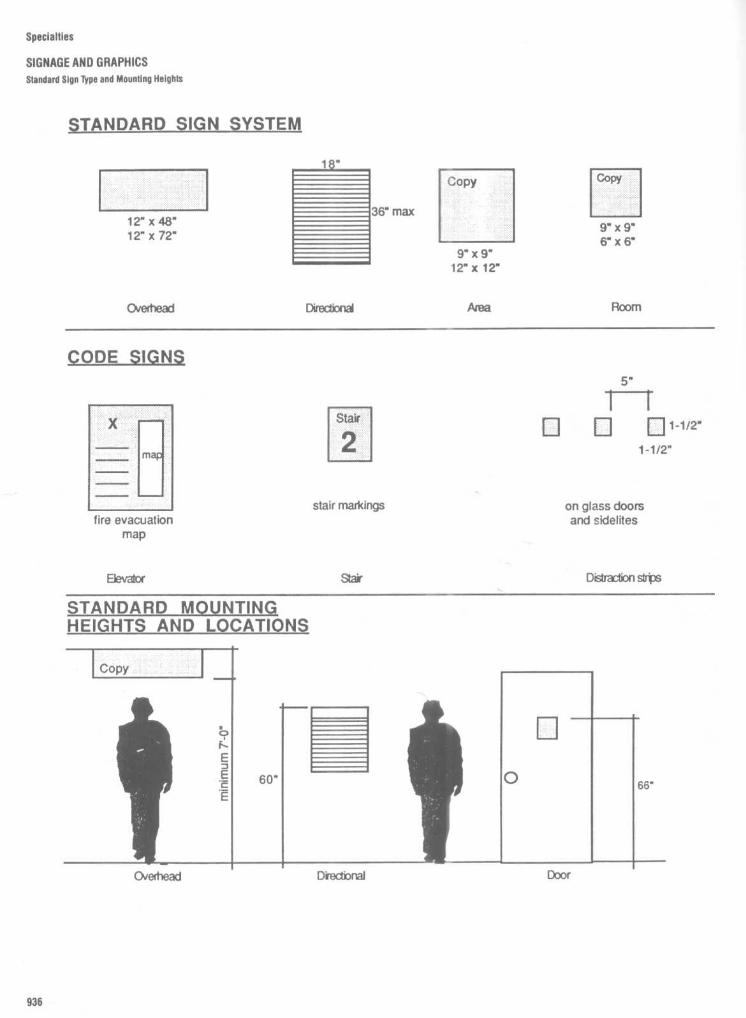
Specialties
SIGNAGE AND GRAPHICSStandard Sign lype and Mounting Heights
STANDARD SIGN SYSTEM

Specialties
SIGNAGE AND GRAPHICS
Sign Type
DIRECTIONAL (CEILING-HUNG)
Material Choices
MDO board, acrylic
Finishes
Painted, plastic laminate, metal laminate
Graphics
Vinyl die cuts, silkscreen, dimensional ap-plied letters
Standard Mounting Detail1 . Threaded rod . pendant, flush2. Scissor clip
Sign Type
DIRECTIONAL (WALL-MOUNTED)
Material Choices
Acrylic, aluminum, acrylic with metal lami-nate face
Finishes
Painted acrylic or aluminum, natural alumi-num or brass (satin or polished), laminatesavailable in standard laminate finishes
Graphics
Silkscreen, front surface or reverse
Standard Mounting Materials
1 . Backpanel: backplate with countersunkscrews with shields ; magnetic, form, or vinyltape with adhesive2 . Strips : vinyl tape
Sign Type
AREA DESIGNATION (WALL-MOUNTED)
Material Choices
Acrylic, aluminum, acrylic with metal lami-nate face
Finishes
Painted acrylic or aluminum, natural alumi-num or brass (satin or polished), laminatesavailable in standard laminate finishes
Graphics
Silkscreen, front surface or reverse ; vinyl diecuts
Standard Mounting Materials
Vinyl or magnetic tape, foam tape, silasticA(IFIPCivp

Specialties
SIGNAGE AND GRAPHICS
Sign Type
ROOM IDENTIFIER (WALL-MOUNTED)
Material Choices
Acrylic, aluminum, acrylic with metal lami-nate face
Finishes
Painted acrylic or aluminum, natural alumi-num or brass (satin or polished), laminatesavailable in standard laminate finishes
Graphics
Silkscreen, front surface or reverse
Standard Mounting Materials
Vinyl tape, foam tape, magnetic tape, silasticadhesive
Sign Type
ROOM IDENTIFIER, CHANGEABLEMESSAGEIWALLMOUNTED)
Material Choices
Holder, acrylic, insert, vinyl
Finishes
Painted (surface or subsurface)
Graphics
Silkscreen or vinyl die cuts
Standard Mounting Materials
Vinyl tape, foam tape, silastic adhesive
6" 6"
Sign Type
FRAMED PLAQUE SIGNS, WALLMOUNTED (previous plaque types areinsertable into standard frame signs)
Material Choices
Molded acrylic, aluminum, brass
Finishes
Painted, satin, polished
Standard Frame Mounting Materials
1 . Frame : screw mount, tape and adhesive2. Insert : adhesive or magnetic tape, Velcromagnet
1-5/8"
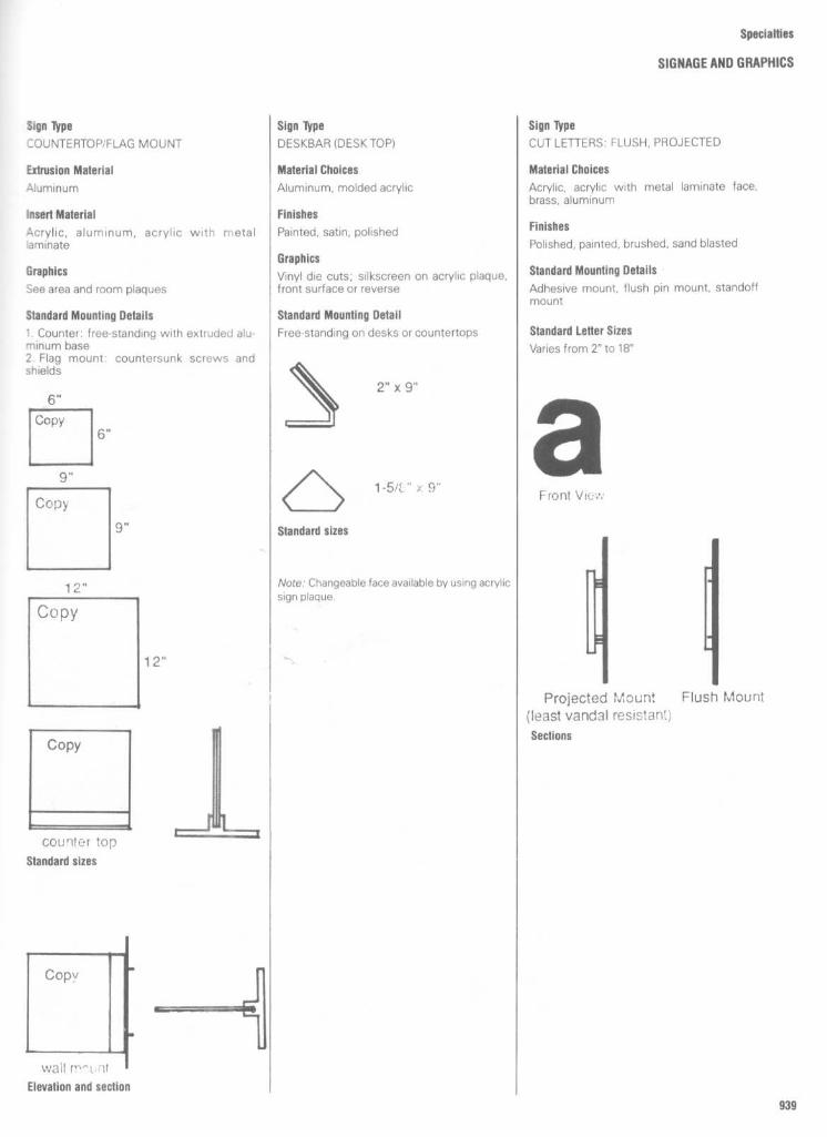
Specialties
SIGNAGE AND GRAPHICS
Sign Type
-OUNTERTOPIFLAG MOUNT
Extrusion Material
Aluminum
Insert Material
acrylic, aluminum, acrylic with metalaminate
Graphics
See area and room plaques
Standard Mounting Details
1 . Counter: free-standing with extrudeu alu-minum base2. Flag mount : countersunk screws andshields
Sign Type
DESKBAR (DESKTOP)
Material Choices
Aluminum, molded acrylic
Finishes
Painted, satin, polished
Graphics
Vinyl die cuts ; silkscreen on acrylic plaque,front surface or reverse
Standard Mounting Detail
Free-standing on desks or countertops
Sign Type
CUT LETTERS: FLUSH, PROJECTED
Material Choices
Acrylic, acrylic with metal laminate face,brass, aluminum
Finishes
Polished, painted, brushed, sand blasted
Standard Mounting Details
Adhesive mount, flush pin mount, standoffmount
Standard Letter Sizes
Varies from 2" to 18"

Specialties
SIGNAGE AND GRAPHICS
Medical Symbols
Medical
HospitalPharmacyDental CareWheelchair
X-RayPhysiotherapyGeneral Medicine, FemaleGeneral Medicine, Male
Coronary CareHematologyUrologyEye
PodiatryMental HealthEar, Nose & ThroatOxygen
ShowerIsolationNurseryLaboratory
ConferenceOccupational TherapyRehabilitationAmbulatory Patients
Nursing HomesMedical ComplexesFirst-Aid Centers
Picto'grafics not shown :1 .516 Parking
1 .413 Health1 .372 Playroom
2.531 Warning1 .150
Library or Reading
1 .147
Chest

Commercial
Cocktail LoungePubCoffee ShopLiquor Store
Mens FurnishingsFurnitureCinemaCamera Store
Gift ShopFloristDress ShopShoe Store
RestaurantSoda FountainGrocery StoreTobacco Shop
BookstoreRecord ShopFuelToy Shop
TheaterVanBeauty SalonBarber Shop
Specialties
SIGNAGEAND GRAPHICS
Commercial Symbols
Shopping Centers
Picto'grafics not shown :Stores & Shops
1 .218
Concrete Mixer
1.226
Flatbed Truck
1.314
Vegetable Produce
Eating Facilities
1 .219
Cushman Vehicle
1.250
Pickup Truck
1 .363
Newspaper VendorCommunity Services
1 .222
Dump Truck
1 .304 Basket
1 .370 Record Store1 .394 Cooking

Specialties
SIGNAGE AND GRAPHICSCommercial and Travel Symbols

Specialties
SIGNAGE AND GRAPHICS
Travel Symbols
Picto'grefics not shown:
1 .350 Motel1 .266
Seaplane Base
Travel
AirportDeparturesArrivalsCar Rentals
BusSubwayTrainTaxi
MonorailFerryCable CarAutomobile
Lost & FoundPorterLockerFuel
Baggage : ;laimCustomsImmigrati,riMoney Exchange
MotorcycleMoving SidewalkLodgingIce Cubes

Specialties
SIGNAGE AND GRAPHICSTravel Symbols
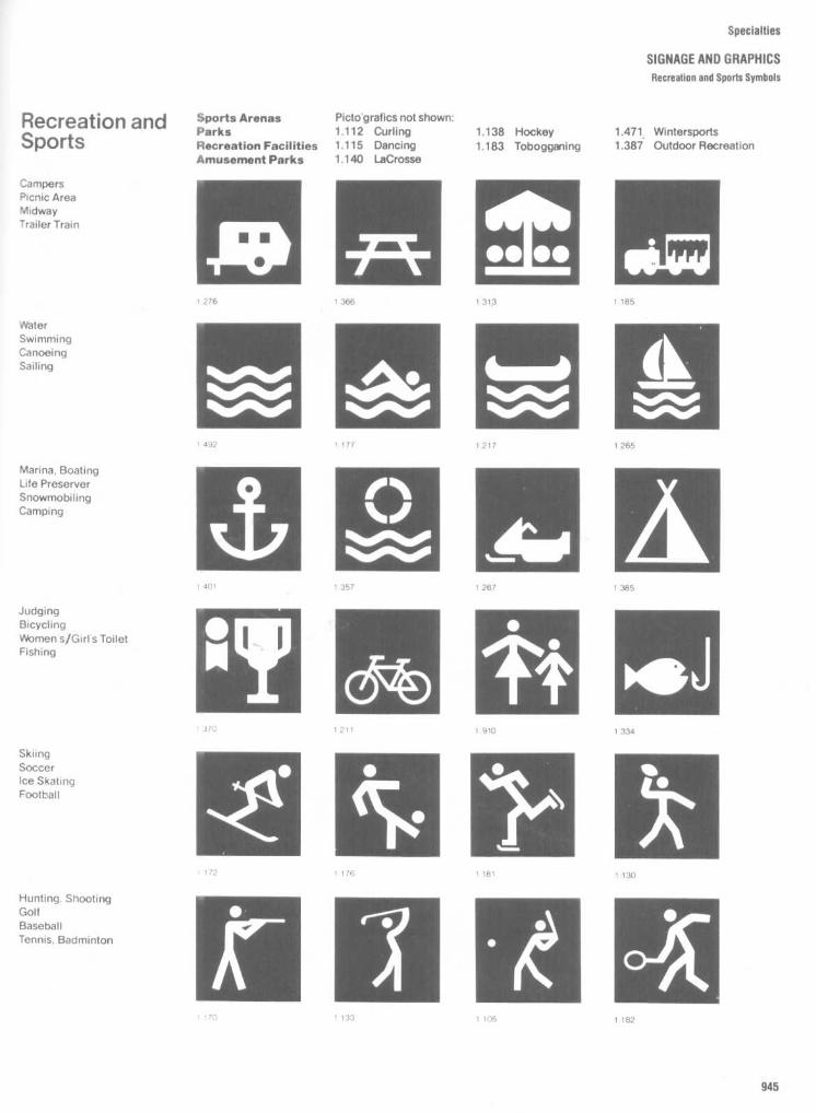
pecialties
SIGNAGE AND GRAPHICS
Recreation and Sports Symbols
Recreation andSports
Sports Arenas
Picto'grafics not shown:Parks
1.112 Curling
1.138 Hockey
1 .471 WintersportsRecreation Facilities
1.115
Dancing
1.183
Tobogganing
1 .387
Outdoor RecreationAmusement Parks
1.140
LaCrosse
CampersPicnic AreaMidwayTrailer Train
WaterSwimmingCanoeingSailing
Marina, BoatingLife PreserverSnowmobi IingCamping
JudgingBicyclingWomen s/Girls ToiletFishing
SkiingSoccerIce SkatingFootball
Hunting. ShootingGolfBaseballTennis, Badminton

Specialties
SIGNALE AND GRAPHICSUniversal Symbols
Universal
EntryExitRampupRampdown
EmergencyWomen's ToiletMen'sToiletStairs
HandicappedNo SmokingTelephoneEscalator
ElevatorDownNo ParkingDrinking fountain
Mail BoxCheck RoomUpNo Entry
ShowerWaiting RoomTelegraph OfficeInformation
Applicable to any
Picto'grafics not shown :building or
1 .110
Children
1 .372
Playroom
1.493
Smokefacility
1 .144
Manwith boy
1 .410
Church
1.516
Parking1 .340
Fragile
1 .472
Synagogue
1 .488
Keep Dry1 .469 Police
1 .155 Janitor

Specialties
SIGNAGEAND GRAPHICS
General Type Styles
Alternate GDIHIC NO 3
AmericanaAmericana IIAUC
AsterAvant Garde COIN, MDIUM
Baker Da nmark 2
Baker Sans MONO REGULAR
Baskerville BOLD ITALIC
BodoniBookmanCaledonia BIXOIIALIC
Caslon BDLD
Century SCHDOLBDDK
Century SCHOOLBOOK BOLD
Cheltenham MEDUM
ColumbusCOPPERPLATE GOTHIC LIGHT
Craw Clarendon BOOK
Craw ClarendonCraw ModernDelta MEDIUM ~
Eastern Souvenir MEIruM
EurostileEurostile BDLD
Eurostile E1(TFNDFD
EurostilB BOLDEXFFNOEO
Fi n IIiII
I)iclc4Folio MEDIUM
Folio MEOIUMEXTFNDEO
Fortune LUIeI
Franklin Gothic
Futura ..UT.Future DEMIBOLD
Garamond ED.
Gerstner Program MEDIUM
Gill SansHarry AT
Hellenic WIDE
Helvetica LIGHT
HelveticaHelvetica Minium
L"Jç (ldc~f ~c~~ MEDIUM OURINF
Horizon MEDIUM
Karen ED.
KorinnaKorinna BDLU
LydianMeliorMelior SEMIBaO
MICROGRAMMA NORMAL
MICROGRAMMA BDLD
MICROGRAMMA
Modula MFOIUM ,
News Gothic .,AU
olive ANUDUE
OptimaOptima SEMIBOLD
PalatinoPalatino SEMIBOLD
Permanent MEDIUM
Perpetua ROMAN
Plantin
BOLDEXTENDED
Quorum MEDIUM
Romane NORMAL
Schadow ANUOUA SFMIBOLO
Serif Gothic REGULAR
Serif Gothic BaD
Solltalre BDLD
Souvenir LGNT
Souvenir MEDIUM ITALIC
Standard MEDIUM
Styrnle B,LD
Times ROMAN
Times ROMAN BOLO
Trool)er ROMAN LIGNI
Trooper ROMAN
Univers 55Univers 56Univers 65Univers 67Univers 53Univers 63
= Le_; DuffLINE
lUI~~M~~C~~3 OUTLINE
')c ç~ 2> OUTLINE
Venus MEDIUM
Venus EXTRABDLO
Venus FXIRABOLDCONOFNSFD
VenusBOLOEXTENDED
Walbaum MEDIUM
WeiSS RUMANFXTRABOLO
Windsor
VV IIndWII OUNINE

Specialties
SIGNAGE AND GRAPHICSGeneral Type Styles
Clarendon Mediumabcdefghijklmnopgrstuvwxyz
A13CDEFGHIJKLMNOPQRSTUVWXYZ
0123456789
Helvetica Mediumabcdefghijklmnopgrstuvwxyz
ABCDEFGHIJKLMNOPQRSTUVWXYZ
0123456789
Optima Regularabcdefghijklmnopgrstuvwxyz
ABCDEFGHIJKLMNOPQRSTUVWXYZ
0123456789 !"$%&'0"Q£:?- ; /,.
Times New Romanabcdefghijklmnopgrstuvwxyz
ABCDEFGHIJKLMNOPQRSTUVWXYZ
0123456789

Specialties
AUDIO-VISUAL SYSTEMSPlanning Guideline Summary
DESIGNING THE SYSTEM
The formulation of a communications pro-gram is based on the functional requirementsdelineated in the feasibility study. The pre-sentation modes to be utilized are a part ofsuch a program . They might include slides,films, videotape, and a sound-recording andplayback system . The detailed design of thefacility includes the selection of basic equip-ment, possible modification of that equip-ment, and provision for additional opticalelements, as well as the engineering of theelectrical control circuitry and the design ofthe electromechanical devices that may beneeded .The implementation of a proposed A-V
system is not merely an exercise in mechan-ical assembly. It is a highly complex processof logistics that involves providing specificfunctional requirements within architecturaland economic constraints. Careful engineer-ing and balancing of the alternatives availablewill generally achieve optimum results .A large number of variables is encountered
in every A-V design problem. As an example,the dimensions of the presentation roomhave a significant effect on the audience size,the acoustic characteristics, the size of theprojected image, the choice of equipment,and the location and the interrelationship ofthe components .The A-V consultant who is responsible for
the program planning, the design, and theengineering of this complex, multifaceteddiscipline should be intimately familiar withthe problems of fabrication, installation, andoperation of such systems . This knowledgewill enable the consultant to plan a facilitywhose execution will not create difficultiesand whose construction and operation canbe effected without costly changes . How-ever, even when the consultant has experi-ence as an adviser to members of thearchitectural and engineering professions,the creation of a well-integrated facility is notnecessarily assured . His or her work and thecompleted facilities should be viewed andevaluated.
Optical AspectsIt is of critical importance for an A-V systemto have the ability to display bright, sharpimages to all viewers and to maintain thestability and consistency of those images in asimple and straightforward manner. The pic-ture quality is a function of a number offactors requiring careful attention during allphases of the project. These include :0 The quality of the original photography
or artwork0 The density, contrast, and sharpness of
the actual material being projectedThe output intensity of the projector
light sourceE The optical characteristics of each pro-
jection unit0 The optical characteristics of the inte-
grated system0 The ratio of the projection distance to
the image sizen The centering integrity of the light path
from the material being projected to itsimage on the screen
The characteristics of the projectionscreen or other viewing surface
Projection Engineering
Room size Ideally, the dimensions of theviewing room should be an outgrowth of theestimate of the audience size that wasestablished in the original A-V study. In manycases, however, the A-V design engineermust utilize a predetermined space. Giventhe characteristics of that space, the de-signer can determine the ideal audience sizefor each type of seating arrangement, andalso ascertain whether a front or rear projec-tion mode is feasible and what the image sizeshould be .The type of relationship that is desired
between the person making the presentationand the audience will determine the seatingconfiguration : theatre, lecture, or conferenceformat . That configuration will in turn dictatethe number of viewers that can be comfort-ably seated for optimum viewing (Fig . 1) .As an illustration, a room 20 feet by 32 feet
can accommodate about 49 people in atheatre configuration (Fig . 2) ; in a lecturearrangement, the audience size would be 24(Fig . 3) ; a U-shaped table would seat 18 (Fig .4) ; and 15 people could fit comfortably at aconference table (Fig . 5) . Circular and multi-use arrangements (Figs. 6 and 7) are addi-tional examples of the relationship of seatingconfiguration and audience size .Other seating configurations have been
devised for other types of communicationprogram modes, each with a direct rela-
tionship between room size and audiencesize . The audience size is also affected by theangle of view between each member of theaudience and the screen (Fig . 1) .Whenever the A-V design engineer has the
opportunity of establishing the dimensionsof the presentation room, he or she should beaware of the important fact that a longerprojection throw for a particular image sizeresults in more even light distribution andsharpness as well as a better angle of view .Consequently a larger audience can be ac-commodated than would be possible using asystem with a short projection distance and anarrower angle of view. This question ofprojection distance applies to both front andrear projection systems . However, as thethrow is normally quite short when a rearprojection screen is used, this factor ofdesign in rear projection facilities is an ex-tremely critical planning element.
Distortion, sometimes called "keystoning,"will result if the viewing surface is notprecisely parallel to the plane of the imagebeing projected. Therefore, the light path,which is usually perpendicular to the pro-jected material, must be carefully controlledin relation to the projector and the screen .The size of the audience and the room, aswell as the mode of projection, will deter-mine whether the screen will be vertical or atan angle (Fig . 8) . Normally, a rear projectionscreen will permit a vertical viewing surface.
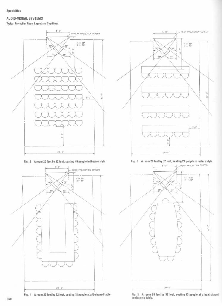
Specialties
AUDIO-VISUAL SYSTEMS
Typical Projection Room Layout and Sightlines

Specialties
AUDIO-VISUAL SYSTEMS
Typical Projection Room Layout and Sightlines

Specialties
AUDID-VISUAL SYSTEMSPlanning Guideline Summary

These variations can accommodate differentfunctional requirements, spatial limitations,and image-quality parameters . Figures 14,15,22, and 23 illustrate some of the possiblearrangements . User requirements and jobconditions will guide the AN engineer in thedesign of a specific system .
The Optical Design FactorA projection system - of whatever nature -is only as good as the quality of the image onthe screen . The clarity, sharpness, resolution,and angle of view that can be expected are adirect result of the thought and care that gointo the optical design of the system . Themore complex the system becomes, themore critical is the system optics . The needfor larger images, sharper images, multipleimages, multiple image sources and theexistence of physically constraining param-eters all add to the conflicting requirementsthat must be satisfied . And they must besatisfied if an acceptable image quality is tobe achieved .
The Sound SystemThe quality and the functional characteristicsof the sound system that is part of anaudiovisual facility are as important as thequality and functional characteristics of theoptical system . The two aspects of a facilityare mutually complementary and the oneshould not be neglected in relation to theother if the goal of an effective and usefulfacility is to be attained .The quality of the sound, as perceived
by the listener, will be influenced by suchfactors as :
The sensitivity of controlsThe quality of the amplifiersThe quality of the speakersThe location of the speakersThe elimination of extraneous soundsThe overall acoustical characteristics of
the spaceThe design factors that govern the func-
tional characteristics of the sound systemmight include the following :
Sound sources: voice, movie sound-track, videotape, audiotape
Telecommunication facilities for outsideprogram sources
Mixing and control requirementsQuantity and placement of speakersRoom size and function : conference
room, classroom, auditoriumProvision for flexibility and future
expansion
The Remote-Control System
Most people who make informational pre-sentations are not audiovisual specialists .Their primary concern is with the materialthey are presenting and notwith the mechan-ics of how it is to be presented . As a result,any control devices they may be required tooperate should be simple and logical . Thepresenter should be asked to make only aminimum of effort to determine how tomanipulate the controls in order to achieve adesired result . The fewer operations neces-sary to reach a particular goal, the better. Forexample, in order for a change to be madefrom one presentation mode to another, itmaybe necessary to alter the ambient roomlighting, reposition a mirror, turn one machine
Specialties
AUDIO-VISUAL SYSTEMSEquipment Arrangement

Specialties
AUDIO-VISUAL SYSTEMSEquipment Arrangement

Specialties
AUDIO-VISUAL SYSTEMSPlanning Guideline summary
off and then another on . If all these things canbe accomplished merely by flipping oneclearly marked switch, the presenter is freedfrom mechanical distractions and can con-centrate full attention on the message beingdelivered . The location and spacing of thevarious switches on the panel, as well as theuse of nomenclature unmistakable to a non-technical person, are important parts of thedesign of a remote-control system that willaid the presenter in the use of the audiovisualfacility.Other considerations that may affect the
design of a remote-control system include :The seating configurationThe room lightingThe number of control points requiredThe use of a lectern incorporating a
control moduleThe number and type of functions to be
controlledThe degree of automation required to
meet system objectives
SUMMARY
An audiovisual presentation facility is nadeup of many components and subsystemswhich are interdependent and must performas an integrated unit . Regardless of its size orscope, the A-V system must be conceived,designed, and installed to function as atotality - as a single entity that works withoptimum efficiency and effectiveness in anunobstrusive manner.
In order to achieve this goal - that ofdeveloping a logical and workable solution toany particular communication problem -careful and detailed preliminary investiga-tions must be made . These will determinethe functional requirements that make up thedesign program . From this program, thespace needs for the equipment and for theaudience can be established early enough inthe development of the project to avoidundesirable procrustean solutions later Theselection, adaptation, manufacture, assem-bly, and installation of equipment and com-ponents should be carefully coordinatedto ensure their functional integrity and per-formance .
Ultimately, a successful audiovisual sys-tem is one that serves as a logical and naturalextension of the human capabilities of theperson using it . It should respond easily andunobtrusively to the communicator's needs,and it should reproduce the material beingcommunicated with the highest possibledegree of fidelity.RECAPFront Projection
1 . Viewing distance factor is 6 . (For exam-ple, if image size is 5 feet the alphanumerics
would be clear at a maximum distance of 30feet to a viewer with a 20140 vision ifcharacters are 3/6 inch on 6- by 9-inch originalcopy area .)
2 . Advantagesa . Good angle of viewb . Good for checking laboratory quality
of all projectualsc . Virtually no apparent falloff to the
sides3 . Disadvantages
a . High ceilings are required to utilize asquare screen to accommodate ver-tical as well as horizontal images .
b. Distraction occurs when the pre-senter or viewers interrupt the lightbeam .
c . Any ambient light adversely affectsimage quality. The room must berelatively dark to achieve the desiredpicture contrast .
d . An overhead projector cannot beused most effectively.
Rear Projection (Rigid or Flexible Material)1 . Viewing distance factor is 7 .5. (For exam-
ple, if image size is 5 feet the maximumviewing distance would be 37 .5 feet .)
2 . Advantagesa . A 20 percent smaller image than is
required by front projection permitsminimum standards to be met in low-ceilinged rooms .
b . Can be used in higher ambient lightconditions .
c . No distracting light beam . (Presentercan more comfortably point atdetails).
d . In a brighter room, the presentereasily maintains eye contact .
e . An overhead projector can be used,so that neither it nor the presenterblocks the image from the viewers .
3 . Disadvantagesa . The inherent grain and directional
quality of the rear screen eliminate itas a viewing medium to determinelaboratory quality of projectuals .
b . The projection system must be de-signed to overcome apparent il-lumination falloff at the sides andimprove the angle of view.
c . Mirrored image is required for properuse .
d . More space is required than withfront projection .
e . Usually costs more .
Seating(Plan should permit several arrangements .)
1 . A U- or Vtable layout provides for best
viewing and viewer/presenter interaction(lowest audience capacity).
2 . Conference table (boat-shape or oval)provides good interaction for conferencesbut not so good as the U- orV-table layout foraudiovisual communication .3 . Random seating style (usually with writ-
ing tablets) is frequently selected for high-level visitor presentations . It permits largercapacity and creates a more luxurious atmo-sphere than the two arrangements above .4 . Classroom style (shallow tables parallel
to front wall with chairs behind) is the nextbest method but less conducive to studentinterraction .
a . Stepped, curved seating (lecture hall)provides unobstructed viewing .
b . When classroom style is contem-plated, study and programmed-learn-ing carrels should be considered .
5 . Auditorium style provides the largestcapacity seating and is generally used forlarge group-orientation and overview typesof presentation .
Rear Projection System Factors1 . The physical center of all projector
lenses must be in perfect alignment with thephysical center of the screen to eliminate any"keystone" effect . (For dissolve mode, 2° offcenter vertically is permitted .)
2 . A front-surface mirror should be used toreverse the image so the equipment can beloaded much as it is for front projection ;slides in magazines need not be reversed,and special reversed prints are not neededfor motion pictures . The use of a mirror canalso extend the projection distance apprecia-bly by folding the light path . Remember, thelonger the projection distance, the better theviewing angle . Minimum projection distanceshould be at least 2 times the image size .3 . The screen-image area should be con-
sidered to be square to accommodate ver-tical and horizontal images unless the systemis to be used for a special, limitedrequirement .4 . Apparent light falloff at the sides can be
diminished or eliminated by increasing theprojection distance and projector illumina-tion . Another minor contributor is slide den-sity. A dense or underexposed slide reducesthe amount of light transmission . This condi-tion increases apparent light falloff .

Specialties
AUDIO-VISUAL SYSTEMSEquipment Arrangement
Fig . 18
An indirect rear projection arrangement using the folded-light-path method, resulting in a ratio of 3 .5 to 1 within the same depth . Thisimproves the image quality and increases the possible viewing angle aswell as allowing rear projection of overhead transparencies with theoverhead projector in the presentation room .
Fig . 17
A deep, indirect-method, rear projection arrangement usingthe minimum recommended ratio of 2 to 1 between projection distanceand image size .
Fig . 19 An indirect rear projection arrangementusing the folded-light-path method and the mini-mum recommended 2 to 1 ratio of projectiondistance to image size . This permits a flexibleequipment arrangement within tight spacelimitations .

Fig . 23
A rear projection arrangement for dual-image and single central-image presentationsutilizing both deep indirect projection and the folded-light-path method .
Fig . 22
A rear-access rear projection arrangement using the folded-light-path method for dual-image or singlecentral-image presentations .
Fig . 21
A front-access rear projection arrangement using the folded-light-path method for dual-image presentations .
Specialties
AUDIO-VISUAL SYSTEMSEquipment Arrangement
Fig . 20 A front-access rear projection arrange-ment using the folded-light-path method for single-image presentations .

Specialties
AUDIO-VISUAL SYSTEMSTypical Projection Room Layout

Specialties
AUDIO-VISUAL SYSTEMSTypical Projection Room Layout

Specialties
AUDIO-VISUAL SYSTEMSTypical Projection Room Layout

Specialties
AUDITORIUM SEATINGSightlines ; Building Codes
Sight line studies vary depending on theparticular event and seating configuration.The following are some basic design ele-ments. (Note . Remember to review andverify slope, riser heights, tread depths, etc.,with pertinent national and local coderequirements .)The visibility profile shown in Fig . 1 :Angle A:
Shifting position to look be-tween heads in row immediately in front ofspectator and over all other heads.
Angle 8:
Shifting position to look be-tween heads of two rows immediately infront of spectators and over all other heads.
Generally, the variables considered in de-termining these angles are:0 3'8" eye level in the seated position0 5" minimum eye clearanceRow spacing and row rise
Angle A is commonly used in determiningfloor slope for auditorium, performing arts ortheater type seating configurations . Whenangle A profile is used in conjunction with astaggered seating arrangement (chairs stag-gered or alternated in arrangement of sizesopposite every other row) it allows unob-structed view of spectators to a determinedfocal point at screen on stage. The finalanalysis is to have all sight lines to intersectthe desired focal point (usually 5'6" elevationeither at screen or 12'0" back from front ofstage).
Angle B is most commonly used in deter-mining riser or stepped applications for gym-nasium, arena, or stadium type seating con-figurations . When the angle B profile is used(generally associated with an aligned seatingarrangement) it allows unobstructed view ofspectators to a determined focal point atcourt line or line of play. The finalanalysis is tohave all the critical sight lines to intersect thefocal point or line of play at generally a 3'0"elevation .
Legal responsibility lies with the ownersand users of equipment in acquiring accep-tance with local officals . The following aresome basic guidelines .
Standard Seating
1 . Row spacing shall provide a clear spaceof not less than 12" (30.5 cm) from the back ofone chair to the front of the most forwardprojection of the chair directly behind it whenmeasured with the self-rising seat in the upposition .
2. Rows of chairs shall not exceed 14chairs between aisles and exceed sevenchairs from an aisle to a row end .3. Aisles serving 60 seats or less shall be a
minimum of 30" (76 cm) wide . Aisles servingmore than 60 seats shall be at least 3'(91 cm)wide when serving seats on one side and atleast 3'6" (107 cm) wide when serving seats
on both sides. These minimum widths, mea-sured at the point furthest from an exit, crossaisles, or foyer shall be increased 1'/2" (3 .8cm) for each 5' (152 cm) in length toward theexit, cross aisle, or foyer. Where egress ispossible in either direction, aisles shall beuniform in width . Dead end aisles are notallowed over 20'0" (61 .0 m) in length .4. Cross aisles, foyer or exit widths shall
be not less than the sum of the requiredwidth of the widest aisle plus 50% of thetotal required width of the remaining aislesthat it serves .
Continental Seating1 . Rowspacing shall provide a clear space
of not less than : 18" (45.7 cm) between rowsof 18 chairs or less ; 20" (50.8 cm) betweenrows of 35 chairs or less ; 21" (53 .3 cm)between rows of 45 chairs or less ; 22" (55.9cm) between rows of 45 chairs or more to amaximum of 100 chairs per row, measuredfrom the back of one chair to the front of themost forward projection of the chair directlybehind it with the self-rising seat in the upposition .2. There shall be exits of 66" (168 cm)
minimum clear width along each side aisle ofthe chair rows for each five rows of chairs .3. Aisles shall not be less than 44" (112 cm)
in clear width.

Specialties
AUDITORIUM SEATINGRow Length

aecialties
AUDITORIUM SEATING
Row Spacing

Specialties
AUDITORIUM SEATINGChair Dimensions

Specialties
AUDITORIUM SEATING
Chair Dimensions and Row Seating

Specialties
AUDITORIUM SEATINGGeneral Seating Arrangement
Seating arrangements in an assemblyspace will either be identified as "multiple-aisle" or "continental ." These terms arecommonly found in design standards man-uals, building codes, and similar architecturalreference documents . Each is unique withspecific guidelines governing row size, rowspacing, and exitways .
Basically, a multiple-aisle arrangement(Fig . 2) will have a maximum of 14-16 chairsper row with access to an aisleway at bothends . If an aisle can be reached from one endof a row only, the seat count may then be
limited to 7 or 8 . It should be noted here that .the maximum quantities will always be es-tablished by the governing building code .
In a continental arrangement (Fig . 3) allseats are located in a central section . Herethe maximum quantity of chairs per row cangreatly exceed the limits established in amultiple-aisle arrangement . In order to com-pensate for the greater length of rows al-lowed, building codes will require wider rowspacing, wider aisles and strategically lo-cated exit doors .
Although more space would appear to be
called for, a continental seating plan is oftennot any less efficient than a multiple-aislearrangement. In fact, carefully planned, acontinental arrangement can frequently ac-commodate more seating within the samespace . For early planning an average 7 .5 sqft . per person may be used . This will includeboth the seating area and space necessaryfor aisleways .

Specialties
AUDITORIUM SEATING
Layout Information
Design Considerations
1 . Layout per applicable building and lifesafety codes, regulations, and ordinances .2. Allow sufficient distance between
aisles for desired quantity and size of chairsplus end space.3. Space rows to allow for proper seat to
back clear space.4. Determine radius or straight rows and
locate by the chair size line .5. Allow 1" minimum clearance from either
side or rear of chair to any adjacent side wall,end walls, etc.6. Provide adequate sightlines for either
sloping or stepped (riser) floor configura-tions.
7 . Seating area should be free ofobstructions .8. To allow for sufficient aisle illumination :
Aisle lights are generally located in the endpanel standards at least every other row.Locate aisle light junction box 6" from thestandard .9. Provide adequate floor or riser materials
for sound anchorage.

Specialties
AUDITORIUM SEATINGRow Seating
Seat Widths Seating comfort is initiallyeslabl-tied by individual chair widths Availables zes range from 18
to 24
however all may notbe produced by a single manufacturer The mostcommonly used chair widths are 20 . 21
and 22It should be noted that these dimensions arenominal being measured from center ro center ofthe support legs If seating comfort is a nighpriority . thought muss be given to a particular Ndthand the space taken up by chair arms todetermine an actual size Usually smaller sizes of18 and 19 have f,nuted application due to theminimum c'ear width provided Typically allmanufacturers size rhe~r chairs along an ~nraginarpline %h,ch may be " eferred 1o as a
datum linechair radius line or a sirruar name For accurateplanning in an assembly a " ea tris line must beident tied so as not to over or underestimate thepotential of a row of cr- airs
Row Spacing Hur. spacing or back to backspacng of seals is also very important indeveloping a comfortable assembly area Aminimum dimension occasionally used is 2 -8132 I This spacing provides marginal clearancebetween a sealed persons knees and the back ofthe chair in the nex'' forward rout At the sametime however ;t will 'equire that a seated personstand to permit the passage of anotnerAs
therow span ng is increased to 3 -0 "'3f
seat ;ng comfort is dramatically ml ancpassage along a row of seated persons isaccor" .plis~ ed :% 1 1, e ,< d <rigr1 On
Floor Design Seating comfort will also beaflecled by the design of the assembly spacefloor . Flat or less steeply sloped floors will usuallyallow a person to extend their knees and legseven under minimum row spacing dimensionsHere an individual can take advantage of the openarea under a seat and the free space created bythe pitched back of a chair As the floor slope isincreased. this free space diminishes Theextreme condition exists where a large elevationchange between rows is combined with aminimum row spacing An example would be a 12'high riser and a 32' wide row spacing At thispoint it becomes necessary to considerincreasing the back to back dimension to providemore leg room
I he "free
space under a chair is also lost when arow of seats is located directly behind a low wallIn this case a recommended minimum clearancewould be 11
measured from seat edge in thelowered position to face of wall The back to backdimension of a row of seals abutting a rear wallshould also be carefully studied Normally thepitched back of a char wily overlap a riser face,automatically reducing the width of that row unlesssucceeding rows are similarly positioned Where arear Yvall exists the recommended procedure is toincrease the dimension of the last row sufficientlyto accommodate any overlap plus a minimalspace between the wall and top edge of the chairback

Visibility in an assembly space is a functionof seat location . As stated earlier, buildingcodes, comfort guidelines, floor design andthe overall form of an assembly space willplay a part in seating arrangements . Thisinformation combined with a basic under-standing of sightline analysis and relatedplanning guidelines can result in achieving anacceptable, if not optimum, level of viewingfor spectators .
Perhaps film projection requires the mostcritical sightline analysis, since poor seatlocation will result in distorted images . Forthis activity the seating parameters are es-tablished by the screen or image size . Anangle of 30° up to 45° measured perpen-dicularto the farand nearedges of the screencan establish a side to side seating limit,while the screen or image height may deter-mine the maximum distance . The minimumdimension or closest recommended seat willalso be set bythe screen height . (It should benoted that these figures are approximate andapply principally to flat screen projection .)
Specialties
AUDITORIUM SEATING
Visibility

Specialties
AUDITORIUM SEATINGEnd Stage; Y4 Arena

Specialties
AUDITORIUM SEATING
End Stage

Specialties
AUDITORIUM SEATINGEnd Stage

Specialties
AUDITORIUM SEATING
3/4 Arena; End Stage

Specialties
AUDITORIUM SEATINGEnd Stage; Wide Fan

Specialties
AUDITORIUM SEATING
End Stage

Specialties
AUDITORIUM SEATINGWide Fan

Specialties
SECURITY
General Control Guidelines
CONTROL OF GROUNDS
Fencing can be a very effective means oflimiting access to secondary exits and tovulnerable ground-level dwellings Fencingfunctions as a control by requiring entrythrough a single, limited, highly visible area .The fencing surrounding most single-familyhomes does not have locked gates. It isintended primarily to protect children, pets,and gardens, and to define the area immedi-ately around the home as the private outdoorspace of that household. Any intrusion intothe area within the fence is therefore notice-able . As a security measure, such fencing,used symbolically, is of minimal value againstpremeditated crime, but it does make crimi-nal intent visible and so is an importantdeterrent.A conventional use of fencing in multi-
family complexes is to limit access to back-yards and windows of a housing cluster Onconventional city blocks, backyards of rowhousing are accessible only through one ofthe houses . However, in many superblockdesigns, such backyards are left open topublic access . In this situation, addition of alimited amount of fencing can protect a largegroup of homes (see Fig. 1) . This approachcan also subdivide the superblock and socreate small, natural clusters .
The Lobby
Improving visibility is the most importantingredient in providing a naturally securelobby It is crucial that a tenant entering abuilding be able to seewhat is going on in thelobby from the outside. Hidden nooks andblind curves provide perfect hiding places .Where such features cannot be removedstructurally, the use of mirrors, windows andimproved lighting mayease the situation
Ideally, a person walking down a pain toenter a building should be able to see anyonestanding in the lobby and elevator waitingarea . In fact, it is often advantageous if thearriving person can see into the elevator fromacross the lobby.
CONTROL OF INTERIOR PUBLICSPACES OF MULTIFAMILYDWELLINGS
The most vulnerable locations in multifamilybuildings are the interior public spaces lob-bies, elevators, stairwells, and corridors.These are areas open to the public butwithout the attending surveillance given apublic street by passersby and police . Thecrimes that occur in these interior publicspaces are the most fearful types of crimes,involving acts of personal confrontation suchas robbery, assault, and rape . Limiting accessto these spaces through the use of a door-man or intercom/door lock system can be ofsubstantial benefit,Lobby visibility discourages a number of
different kinds of crime. Crimes of personalconfrontation may be deterred primarily be-cause the potential victim can readily per-ceive and avoid a suspicious person in thelobby The potential criminal must also fearthe possibility that another tenant or thepolice may be viewing the crime in the well-litopen area .
Mailbox crime - generally the theft ofchecks - can be deterred when mailboxesare located in a highly protected area of thelobby. This protection can consist of placingthe mailboxes behind an intercom or in alocked mailroom . It is essential that themailboxes be visible from as many differentviewpoints as possible . Improved visibility inthis context can be a significant deterrentto crime.Some managers designate an area of the
lobby as a legitimate resting place, wherechairs and other lounging items are provided .Lounging may aid security, particularly if thebuilding includes a high proportion of elderly.The best locations for such seating are areaswith high visibility. Often tenant patrols usethis space as a station and provide stillanother dimension of security.A bulletin board is an inexpensive device
that can improve lobby security by providinga diversion . If, for example, a tenant entersthe lobby and sees someone she doesn'trecognize waiting for an elevator, she mayneed a reasonable excuse for not taking thesame elevator. The bulletin board providesthe tenantwith a natural excuse to pause andsurvey the situation .The area around the main entry to a
multifamily building should be clearly distin-guished from the public walkway whichleads to it . A person entering through themain door should feel distinctly that he isentering a space controlled by the residentsof the building . The main entry should be welllit and clearly visible from outside .
Entry doors should be constructed of atransparent material covering as large an areaas possible . In vandalism-prone areas, themain entry doors should be made of unbreak-able glass or other similar, very sturdy trans-parent material . Because of the need forgood visibility, replacing glass panels withmetal or other material should be avoided .For window walls and doors where theincidence of vandalism is extreme, glasspanels less than 2 feet from the ground andhigher than 7 feet from the ground may bereplaced by solid materials .
Fire Doors and Fire Stairs
Secondary exit doors are the weakest link insecurity of buildings . An ideal secondary exitdoor would be one that allows exit but notentrance . Unfortunately, there is no accept-able emergency exit system that allowsegress only.
In the design of any security system thereis a continuing clash between the need forsecurity against crime and the need forsafety in case of fire . Fire doors are fre-quently used for entry and exit by criminals.Installation of panic hardware and the ab-sence of exterior hardware sometimes pre-vent criminal use. These measures will notsuffice, however, where tenants do not coop-erate in avoiding use of secondary exits andensuring they are kept closed .
To a large extent, the design and location ofsecondary fire exits determine tenant at-titudes about the exits. For example, a build-ing's main entry may face the street, but theparking lot may be to the rear of the building .If the secondary exit is also at the rear andclose to this destination, the temptation touse the fire door as an entry or exit will bedifficult to resist . Similarly, security is de-creased in buildings where the main entriesface the interior of the project while the firedoors face the surrounding streets with theirparking and shopping facilities . Where thefire exit does not represent any shortcut orimproved convenience to the tenant, it is farmore likely to remain closed . A securelydesigned building is one in which the firedoor exits to an area that is less convenient ordesirable than the area outside the main door.
In cases of persistent breaks in security ofsecondary exits, it is possible to modify thebuilding plan at the ground level and open anew doorway in a better location . However,this improvement is costly and can only bedone where architecturally possible .
Another architectural modification to im-prove security involves making a fire exit intoa legitimate secondary entry and developinga security system that protects both the mainand secondary entries. If a fire door exits to a
977
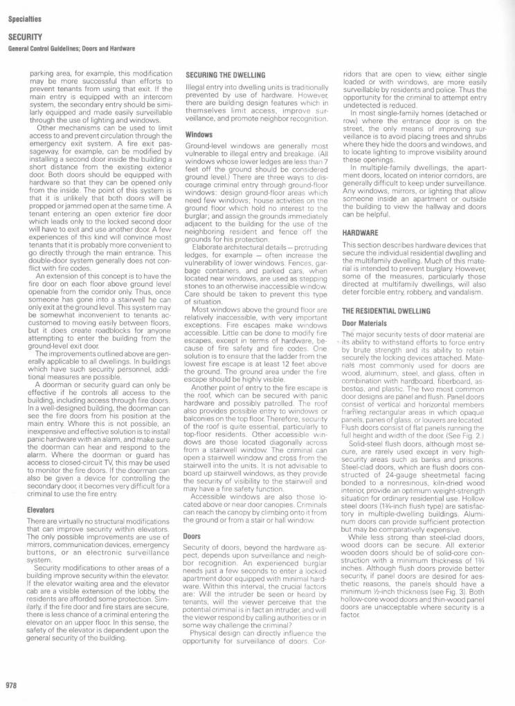
Specialties
SECURITYGeneral Control Guidelines; Doors and Hardware
parking area, for example, this modificationmay be more successful than efforts toprevent tenants from using that exit . If themain entry is equipped with an intercomsystem, the secondary entry should be simi-larly equipped and made easily surveillablethrough the use of lighting and windows .Other mechanisms can be used to limit
access to and prevent circulation through theemergency exit system . A fire exit pas-sageway, for example, can be modified byinstalling a second door inside the building ashort distance from the existing exteriordoor. Both doors should be equipped withhardware so that they can be opened onlyfrom the inside . The point of this system isthat it is unlikely that both doors will bepropped orjammed open at the same time . Atenant entering an open exterior fire doorwhich leads only to the locked second doorwill have to exit and use another door. A fewexperiences of this kind will convince mosttenants that it is probably more convenient togo directly through the main entrance . Thisdouble-door system generally does not con-flict with fire codes .An extension of this concept is to have the
fire door on each floor above ground levelopenable from the corridor only. Thus, oncesomeone has gone into a stairwell he canonly exit at the ground level . This system maybe somewhat inconvenient to tenants ac-customed to moving easily between floors,but it does create roadblocks for anyoneattempting to enter the building from theground-level exit door.The improvements outlined aboveare gen-
erally applicable to all dwellings . In buildingswhich have such security personnel, addi-tional measures are possible .A doorman or security guard can only be
effective if he controls all access to thebuilding, including access through fire doors .In a well-designed building, the doorman cansee the fire doors from his position at themain entry. Where this is not possible, aninexpensive and effective solution is to installpanic hardware with an alarm, and make surethe doorman can hear and respond to thealarm . Where the doorman or guard hasaccess to closed-circuit TV, this may be usedto monitor the fire doors . If the doorman canalso be given a device for controlling thesecondary door, it becomes very difficult foracriminal to use the fire entry.
ElevatorsThere are virtually no structural modificationsthat can improve security within elevators .The only possible improvements are use ofmirrors, communication devices, emergencybuttons, or an electronic surveillancesystem .
Security modifications to other areas of abuilding improve security within the elevator.If the elevator waiting area and the elevatorcab are a visible extension of the lobby, theresidents are afforded some protection . Sim-ilarly, if the fire door and fire stairs are secure,there is less chance of a criminal entering theelevator on an upper floor. In this sense, thesafety of the elevator is dependent upon thegeneral security of the building .
SECURING THE DWELLINGIllegal entry into dwelling units is traditionallyprevented by use of hardware . However,there are building design features which inthemselves limit access, improve sur-veillance, and promote neighbor recognition .
WindowsGround-level windows are generally mostvulnerable to illegal entry and breakage . (Allwindows whose lower ledges are less than 7feet off the ground should be consideredground level .) There are three ways to dis-courage criminal entry through ground-floorwindows : design ground-floor areas whichneed few windows ; house activities on theground floor which hold no interest to theburglar ; and assign the grounds immediatelyadjacent to the building for the use of theneighboring resident and fence off thegrounds for his protection .
Elaborate architectural details-protrudingledges, for example - often increase thevulnerability of lower windows . Fences, gar-bage containers, and parked cars, whenlocated near windows, are used as steppingstones to an otherwise inaccessible window.Care should be taken to prevent this typeof situation .
Most windows above the ground floor arerelatively inaccessible, with very importantexceptions . Fire escapes make windowsaccessible . Little can be done to modify fireescapes, except in terms of hardware, be-cause of fire safety and fire codes . Onesolution is to ensure that the ladder from thelowest fire escape is at least 12 feet abovethe ground . The ground area under the fireescape should be highly visible .
Another point of entry to the fire escape isthe roof, which can be secured with panichardware and possibly patrolled . The roofalso provides possible entry to windows orbalconies on the top floor. Therefore, securityof the roof is quite essential, particularly totop-floor residents . Other accessible win-dows are those located diagonally acrossfrom a stairwell window. The criminal canopen a stairwell window and cross from thestairwell into the units . It is not advisable toboard up stairwell windows, as they providethe security of visibility to the stairwell andmay have a fire safety function .
Accessible windows are also those lo-cated above or near door canopies . Criminalscan reach the canopy byclimbing onto it fromthe ground or from a stair or hall window.
DoorsSecurity of doors, beyond the hardware as-pect, depends upon surveillance and neigh-bor recognition . An experienced burglarneeds just a few seconds to enter a lockedapartment door equipped with minimal hard-ware. Within this interval, the crucial factorsare : Will the intruder be seen or heard bytenants, will the viewer perceive that thepotential criminal is in fact an intruder, and willthe viewer respond by calling authorities or insome way challenge the criminal?
Physical design can directly influence theopportunity for surveillance of doors . Cor-
riders that are open to view, either singleloaded or with windows, are more easilysurveillable by residents and police . Thus theopportunity for the criminal to attempt entryundetected is reduced .
In most single-family homes (detached orrow) where the entrance door is on thestreet, the only means of improving sur-veillance is to avoid placing trees and shrubswhere they hide the doors and windows, andto locate lighting to improve visibility aroundthese openings .
In multiple-family dwellings, the apart-ment doors, located on interior corridors, aregenerally difficult to keep under surveillance .Any windows, mirrors, or lighting that allowsomeone inside an apartment or outsidethe building to view the hallway and doorscan be helpful .
HARDWAREThis section describes hardware devices thatsecure the individual residential dwelling andthe multifamily dwelling . Much of this mate-rial is intended to prevent burglary. However,some of the measures, particularly thosedirected at multifamily dwellings, will alsodeter forcible entry, robbery, and vandalism .
THE RESIDENTIAL DWELLINGDoor MaterialsThe major security tests of door material areits ability to withstand efforts to force entryby brute strength and its ability to retainsecurely the locking devices attached . Mate-rials most commonly used for doors arewood, aluminum, steel, and glass, often incombination with hardboard, fiberboard, as-bestos, and plastic . The two most commondoor designs are panel and flush . Panel doorsconsist of vertical and horizontal membersframing rectangular areas in which opaquepanels, panes of glass, or louvers are located .Flush doors consist of flat panels running thefull height and width of the door (See Fig . 2 .)
Solid-steel flush doors, although most se-cure, are rarely used except in very high-security areas such as banks and prisons .Steel-clad doors, which are flush doors con-structed of 24-gauge sheetmetal facingbonded to a nonresinous, kiln-dried woodinterior, provide an optimum weight-strengthsituation for ordinary residential use . Hollowsteel doors (13/4-inch flush type) are satisfac-tory in multiple-dwelling buildings . Alumi-num doors can provide sufficient protectionbut may be comparatively expensive .While less strong than steel-clad doors,
wood doors can be secure . All exteriorwooden doors should be of solid-core con-struction with a minimum thickness of 1 3/4inches . Although flush doors provide bettersecurity, if panel doors are desired for aes-thetic reasons, the panels should have aminimum 1/2-inch thickness (see Fig . 3) . Bothhollow-core wood doors and thin-wood paneldoors are unacceptable where security is afactor

Specialties
SECURITYDoors and Hardware
Door FramesThe sides and top of a doorway are providedwith a door frame which holds the door inposition . The side members of the doorframe are called jambs ; the top member iscalled the head (see Fig . 4). The strike is theportion of the jamb which is cut out or drilledout to allow installation of a metal plate,which accepts the latch or bolt from the doorlock (see Fig . 5) .Wooden frames provide an unacceptable
level of security unless they are at least 2inches thick . Metal-covered wood framesprovide an optimum cost-security invest-ment when used in combination with metal-covered wood doors . If a hollow steel frameis used, the residual air space behind theframe should be filled with a crush-resistantmaterial such as cement grout, especially inthe area of the strike (see Fig . 6) . This willprevent an intruder from wedging a crowbarbetween the door and frame and crushing
the frame to free the lock .For doors swinging in, rabbeted jambs
should be used . These are jambs containing ametal extension that protrudes beyond theedges of the closed door, thus preventingtampering in the area of the strike (see Fig . 7).
For doors without rabbeted jambs, anLshaped piece of angle-iron at least 2 feetlong, mounted in the area of the strike, givesextra protection (see Fig . 8) . The iron acts as alip which protects the strike from attack .

Specialties
SECURITY
Doors and Hardware
For doors opening out, a flat metal plate,called an escutcheon plate, can be mountedto the face of the door in the area of the lock .This plate, which extends beyond the edge ofthe door and fits flush with the jamb whenthe door is closed, will protect the lock fromattack in the area of the strike (see Fig. 9) .
All plates located on the outsides of doorsshould be attached with tamper-resistantconnectors such as round-headed carriagebolts or one-way screws .
Door Hinges and Closers
Spring hinges close the door automatically byusing spring force . A spring hinge prevents a
criminal from slipping in behind a residentwhohas neglected to close the door immedi-ately upon entering . Also, spring hingesprevent the resident from leaving the dooropen when he exits. Door closers (see Fig.10) serve the same purpose. These are formore heavy duty and are commonly used inlobbies and commercial facilities .
Hinges should be mounted on the inside ofthe door so that burglars cannot remove thedoor from the hinges to enter. If hinges mustbe placed on the outside, they should havenonremovable pins . Pins can be made non-removable by peening the straight end or bydrilling and tapping a machine screw into the
middle portion of each pin from the inside ofthe open hinge (see Fig. 11) . Doors withoutside hinge pins can also be protected byscrewing two screws halfway into the jambedge of the door. One screw is placed neareach hinge, and a receiving hole is drilled intothe jamb for each screw. These protrudingscrews hold the door when it is closed, evenif the hinge pins are removed.

Specialties
SECURITY
Doors and Hardware
Door Locks
Locks must withstand or seriously delay notonly a simple forced entry but also sophisti-cated criminal attack . Locks may also guardagainst window entry-door exit crimes .
Parts of the a lock are defined as follows :Cylinder: A cylinder is that part of the
lock into which the key is inserted . If theproper key is used, the cylinder will allow thekey to turn, thus moving a bolt or latch.
Deadbolt: A deadbolt (or bolt lock) is aheavy metal bar which moves horizontallyinto the strike of the doorjamb, thus lockingthe two together. It is called a deadboltbecause it cannot be pushed back unless theknob is turned by the correct key.
Latch: A latch (or spring lock) is the partof the lock that keeps the door in a closedposition by extending into the strike automatically when the door is closed . The latch ismost often operated by the doorknob . Mostlatches can be pushed back by externalpressure without having to turn thedoorknob .
Deadlatch: In a deadlatch, the latch ispositively held in the projected position by anautomatic mechanism which is depressedagainst the strike plate (see Fig. 12) .
Strike : The strike is the portion of thejamb where a metal plate has been placedto receive the deadbolt and/or the latch(see Fig. 5) .
Stopworks: Stopworks consist of twobuttons located under the latch. Pressing thetop button in allows the doorknob to turnfreely and operate the latch, from both insideand out. Pressing the lower button in allowsthe inside doorknob to operate the latch, but"freezes" the outside doorknob.
Throw: The throw of a lock is the length(in inches) that the deadbolt extends beyondthe face of the lock .
Primary locks
Primary locks operate in con-junction with the latch . There are two majortypes : mortise locks and cylindrical orbore-intubular locks (commonly called key-in-the-knob locks).
Mortise locks (see Fig. 13) are more com-mon than key-in-the-knob locks and will pro-vide good security. All mortise locks withlatches should contain a deadbolt with atleast a 1-inch throw constructed of case-hardened steel, brass or zinc alloy, or bronze .Federal FF-H 106a heavy-duty series 86 mor-tise locks or 185 latch and 190K modifieddeadbolts are recommended . The deadboltand latch should be key-operated from theexterior and operated from the inside by adevice not requiring a key.
Mortise locks with latches used in resi-dences should not contain an automaticspring latch with stopworks . Although stop-works prevent the outside knob from beingturned, they leave the premises open to easyentry because they do not prevent the latchfrom being pushed back . An intruder needonly insert a credit card into the strike area,push back the spring latch, and open the door(called "loiding" or "shimming" the lock). Inlocks without stopworks, the deadbolt(which cannot be loided) must be thrown bythe key of the resident . Eliminating thestopworks prevents the residentfrom relyingon the stopwork and latch mechanism alone.
Key-in-the-knob locks (see Fig . 14) are lesssecure than mortise locks. Although inex-
pensive due to easy installation, key-in-the-knob locks can be easily gripped bya tool andtwisted until they break. A key-in-the-knoblock can include a deadbolt, at a comparableto slightly higher price than a mortise lock .
Secondary locks
Asecondary lock (rim lock)operates independently of the latch ."Secondary" is perhaps a poor name, sincethis type of lock is essential for good security.Secondary locks are usually mounted abovethe primary lock at shoulder level . They areoperated by a key from the outside, and by aturnbolt from the inside . Both mortise andsecondary locks may require keys to openthem from inside and outside - useful whereaccess to premises maybe gained through asmall opening other than the door (windowtransom), since this will prevent the thieffrom using the door to remove large objectsor to escape .There are three major types of secondary
locks : spring bolt, horizontal deadbolt, andvertical deadbolt . The spring bolt lock oper-ates much the same as the primary doorlatch. Because the bolt must be springloaded and bevelled to allow automatic latch-ing, the bolt can be easily opened . A button(slide stop) maybe set to deadlock the bolt.However, the button must be set from the
inside and can only be used when anothermeans of egress is available . The spring boltis not recommended as a secondary lock(see Fig. 15) .
Horizontal bolt rim locks operate much thesame as deadbolts on primary locks. Whilehorizontal deadbolts afford much better pro-tection than spring bolts, they still can beeasily overcome . By inserting a crowbarbetween the door and the jamb, the intrudercan pry them apart to release the bolt fromthe strike . For this reason, the longer thethrow of the deadbolt, the greater protec-tion it affords. However, throws of over 1 112inches may have excessive cantilever. Therecommended minimum throw is 1 inch(see Fig. 16).
Vertical bolt deadlocks should be used assecondary locks wherever possible . Theseutilize two deadbolts that fit vertically intoeyeholes or sockets attached to the jamb .This creates a firm bond between the doorand the jamb . The vertical bolt deadlockmade by Segal is highly recommended, bothfor its pressed-steel construction and for itsability to hold up under heavy use (see Fig .17). For additional security, a pick-resistantcylinder should be installed in a good verticaldeadbolt body. This combination providesexcellent security.
981

Specialties
SECURITYDoors and Hardware

Specialties
SECURITYDoors and Hardware
The locks discussed so far rely on therigidity of an existing door frame to resistattacks on the lock . Since older buildings maycontain weak door frames, a buttress-typedoor lock is advisable . Locks of this typeinclude a bar set against a plate on the doorand into a receptacle in the floor, thus forminga triangular buttress (see Fig . 18) . Most ofthese locks can be operated only by a keyfrom the outside . The Magic Eye Companybuttress lock can be operated from theoutside by a key and from the inside by aturnbolt to prevent accidental locking (seeFig . 19) . One model contains a heavy-dutydeadbolt as well as the buttress bar, andaffords still further protection (see Fig . 20) .The double-bar lock may also be used to
increase the strength of a door, by means oftwo steel bars that extend up to 21/2 inchesinto each side of the jamb (see Fig . 21) . Thecyclinder is protected on the outside by anescutcheon plate to prevent forcible re-moval . A pick-resistant cylinder can be in-stalled for added protection . The Fox PoliceLock and the Fichet Locking Bar are exam-ples of high-quality double-bar locks .
Cylinders Regardless of the type of lockpurchased, the cylinder is critical in providingprotection . It must withstand efforts bysophisticated criminals such as lock pickexperts .The cylinder is the part of the lock into
which the key is inserted . The most commontype of cylinder is the pin tumbler whichoperates as follows : As the key is inserted,spring-loaded pins are raised to the properposition to allow the barrel and the key toturn ; the turning causes the bolt or latch (orboth) to move . If the wrong key is used, thepins will line up incorrectly and prevent thebarrel from turning (see Fig . 22) .
Recently, cylinders have become availablewhich utilize special keyways and keys tomake the cylinder pick proof or pick resistant(see Fig . 23) . Medeco, Illinois Duo, Sargent,Keso, Eagle Three Star, Mela, Fitchet, andMiracle Magnetic are highly pick resistant .Such cylinders provide improved security,but may require registered keys that can beduplicated only at the factory upon receipt ofa signed request . A compromise is the use ofa key type whose blank is not availablenormally, but for which spare blanks are keptfor replacements .Of all cylinders on the market, Medeco has
proven most difficult to overcome . Medecoutilizes twisting tumblers operated by a keywith angular or criss-cross cuts . Only if theproper key is inserted will the pins twist theexact amount needed to allow the barrel toturn .
If special keyway cylinders are deemedunnecessarily secure or costly (Medeco cyl-inders cost about two times the next ade-quate), the cylinder used should be of solid-bar-stock bronze and machined for a tight fit .The cylinders of a master-key system of
locks are constructed so that individual keysfit only one lock, but a single master key canopen all locks in the system . Use of a master-key system makes maintenance and otherauthorized access simpler, but the dangers ofimproper use of a lost or stolen master keyfar outweigh the benefits .From a security standpoint, a cylinder
should have at least six pins . This oftenresults in the cylinder being longer than the
no12

thickness of the door In mortise locks (whichare recessed into doors), a six-pin cylinderoften extends slightly beyond the surface ofthe door, thus making it susceptible to forci-ble removal by use of a gripping tool . Toprevent use of such a tool, protruding cylin-ders should be protected by one of thefollowing :
Spinner ring . A hardened steel ring thatforms a collar around the cylinder and whichspins freely around the cylinder whengripped (see Fig . 24).
Bevelled-ring cylinder guard: A case-hardened steel ring thatprevents the cylinderfrom being gripped by a tool because of itsbevelled shape (see Fig. 25). Scotsmanmakes a flat, very secure, cylinderguard ring .
Escutcheon plate : A metal platemounted to the door, which covers all of thecylinder except the core (the part where thekey is inserted), thus protecting the cylinderfrom attack . The escutcheon plate should beconstructed of malleable cast iron and at-tached to the door with one-way screws .Machine bolts should not be used to mountescutcheon plates on mortise locks, as theincreased pressure can have an adverseeffect on the mechanism (see Fig. 26) .
Sliding Doors
Sliding doors opening onto a ground-levelpatio or accessible balcony (on the first flooror top floor, or adjacent to other balconies)should be constructed so the movable sec-tion of the door slides on the inside of thefixed portion . Sliding doors should be breakresistant (plate glass) and equipped with avertical-bolt Segal lock (see Fig. 27), whichuses a hook-type bolt to grip door and frametogether, or a Loxem Sli-door lock that hoodsat top and bottom (see Fig. 28).
Specialties
SECURITY
Doors and Hardware

Specialties
SECURITYDoors and Hardware
Doors with Large Glass PanelsExterior doors containing panes of glassare not recommended for security. Frenchdoors that open out should have hingeswith nonremovable pins . The vertical stileincorporating the lock should withstand aconcentrated horizontal load of 300pounds . The doors should contain a mor-tise-type lock that is key operated from theinside and outside . The lock should con-tain a pin-tumbler cylinder with at least sixpins (a pick-resistant cylinder can be usedfor extra protection) .
Even when fitted with key-operatedlocks inside and outside, doors with largepanes of glass are a security problem . Useof break-resistant glass substitutes is onemodification . Bars or metal grilles, whileproviding good security, may be aesthet-ically unacceptable . Alarms may also beused on these vulnerable doors .
Double DoorsOn double doors, the active leaf should beequipped with a mortise-type lock . Theinactive leaf should be equipped with flushbolts with at least a 3/4-inch throw at headand foot (see Fig . 24) .
Private Garage DoorsMany rolling overhead doors operated byelectric motors offer adequate securitybecause the motors are controlled by a keyswitch inside the garage or by a low-powerradio transmittor Manually operated doorsshould be provided with slide bolts on thebottom bar (see Fig . 30) . Chair-operateddoors should be provided with a cast-ironkeeper and pin for securing the hardened-steel chain .
Door InterviewersInterviewers are devices installed on anopaque door to allow residents to see andhear who is outside the door withoutopening it .

An optical interviewer (peephole) shouldbe installed on each door that provides entryinto private dwellings . Many types of inter-viewers are available, ranging in diameterfrom two-tenths of an inch to 3 inches .Optics of the interviewer include one-wayglass, plastic, and wide-angle glass.
Interviewers with openings of over one-quarter of an inch are not recommended.Larger interviewers can easily be punchedout to allow insertion of tools to open thedoor from the inside . Someone also maystick a knife, wire, or gun through the holewhile the person is looking through it . Inter-viewers are located approximately 4 feet 9inches from the floor (see Fig . 31). The bestinterviewers contain a double glass forsafety. Wide-angle glass allows maximumvisibility. Although a wide-angle lens doesproduce a curved, "fisheye" image, clarity ofthe image is not impaired . If wide-angle glassis not used, the person outside cannot beseen unless he is standing in adirect line withthe interviewer (see Fig . 32)
Instead of an optical interviewer, a case-hardened steel chain which fits into a hori-zontally mounted slide track on one end ofthe door jamb maybe installed (see Fig . 33).The chain allows the door to open slightly(preferably not more than 2 inches) to permiteasy conversation without fully unlocking thedoor These chains should be used for inter-viewing only, not to protect a locked door. Theswing of the door, even if only 2 inches,allows the criminal to exert strong force withmomentum, which breaks most chain de-vices. The interviewing space also allowsinsertion and use of tools. Some slide chainshave a locking mechanism which preventsuse of a thumb tack (or piece of tape) andrubber band to pull back the slide mechanismand remove the chain from the track. Evenwhen equipped with a locking mechanism,steel chains and slides are readily overcomeby simple tools and brute force .
Window Materials
Because windows contain large sections ofglass, they naturally impose a security prob-lem. Windows most vulnerable are those onthe first floor (or otherwise accessible fromthe ground) and those leading to fire es-capes . Less vulnerable, but still easilyreached, are windows over a canopy (asabove a main entrance), windows adjacent tostairwell windows, and windows on the topfloor.Window Locks
Among the common window locks are thecrescent sash lock, often standard on resi-dential windows; various friction or pressuredevices, such as the thumb-screw latch ; pin-type latches, such as the simple steel pin-in-the-hole device ; and the slide-bolt latch. All ofthese devices can easily be overcome, es-pecially if an intruder is willing to risk thenoise of breaking a small section of the glass.(See Figs . 34, 35, 36, and 37 .)Normal windowpane glass is approx-
imately one-eighth of an inch thick, es-tremely brittle, and breaks easily Plate glassis usually one-quarter of an inch thick andtempered to withstand an accidental knock.Plate glass is used forlarger areas because ofits greater strength and because the initialcost is worth the extra protection . Tempered
Specialties
SECURITY
Doors and Hardware ; Windows and Hardware

Specialties
SECURITY
Windows and Hardware
glass has a thin, hardening coating and, whileno stronger than plate glass, will not cutsomeone who breaks it .
Several companies have developed un-breakable, transparent polycarbonate mate-rials which look like glass but are very difficultto break . GE's Lexan, for example, is guaran-teed unbreakable . It costs twoto three timesas much as glass and has low resistance toscratching . An improved material, LexanMR-4000, is slightly more expensive but ismuch less easily scratched . These polycarbo-nate materials have not yet been extensivelyused for private dwellings .Another type of durable "glass" is fabri-
cated much like the safety glass used inautomobiles : two layers of high-quality glassare bonded together with a layer of toughvinyl between . This is sold by one companyas Secur-lite . While Secur-lite can eventuallybe broken, the noise and trouble required todo so are considerable deterrents .
Oversized glazed areas should be avoided .Anything beyond standard size (6 feet by 8feet for glass, for example) is expensive andmay be difficult to obtain .The only reliable devices are those with a
key-operated locking mechanism . Yale andIdeal Security manufacture a window lockwhich is a modification of the pin-type lock . It
can be locked in either of two positions, oneof which allows the window to be openslightly at the bottom for ventilation (see Fig .38) . Fox makes a window lock combining apin-type lock and a hasp and padlock . Al-though somewhat unsightly, it provides ex-cellent protection . Ideal Security manufac-tures a modification of the crescent sash lockwhich requires a key to operate .
All of these devices provide adequatesecurity for normal residential use . A set ofkeys should be convenient to the window foruse in emergencies but far enough away sothat a burglar cannot reach them .
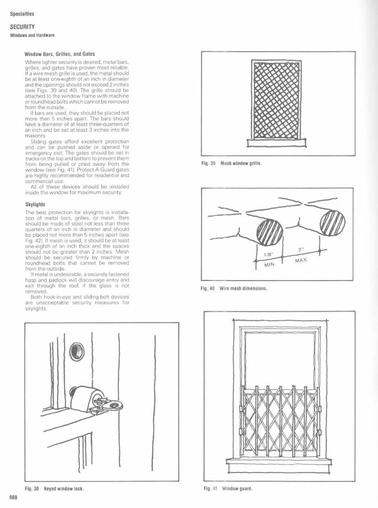
Window Bars, Grilles, and Gates
Where tighter security is desired, metal bars,grilles, and gates have proven most reliable .If a wire mesh grille is used, the metal shouldbe at least one-eighth of an inch in diameterand the openings should not exceed 2 inches(see Figs . 39 and 401. The grille should beattached to the window frame with machineor roundhead bolts which cannot be removedfrom the outside.
If bars are used, they should be placed notmore than 5 inches apart. The bars shouldhave a diameter of at least three-quarters ofan inch and be set at least 3 inches into themasonry.
Sliding gates afford excellent protectionand can be pushed aside or opened foremergency exit . The gates should be set intracks on the topand bottom to prevent themfrom being pulled or pried away from thewindow (see Fig. 41). Protect-A-Guard gatesare highly recommended for residential andcommercial use.
All of these devices should be installedinside the window for maximum security.
Skylights
The best protection for skylights is installa-tion of metal bars, grilles, or mesh . Barsshould be made of steel not less than threequarters of an inch in diameter and shouldbe placed not more than 5 inches apart (seeFig. 42). If mesh is used, it should be at leastone-eighth of an inch thick and the spacesshould not be greater than 2 inches . Meshshould be secured firmly by machine orroundhead bolts that cannot be removedfrom the outside.
If metal is undesirable, a securelyfastenedhasp and padlock will discourage entry andexit through the roof, if the glass is notremoved .
Both hook-in-eye and sliding-bolt devicesare unacceptable security measures forskylights .
Specialties
SECURITY
Windows and Hardware

Specialties
SECURITYDoors and Hardware; Elevators
MULTIFAMILY DWELLINGS
Lobby Doors and Walls
All lobby entrance doors should provide max-imum visibility of the lobby This often re-quires large glass areas in the lobby doors.Where there is a high degree of vandalismand crime, use of Lexan is recommended. Inall cases, oversized glass sheet should beavoided. Glazed areas should be divided sothat sheets larger than 6 by 8 feet are notneeded . The doorframe should be con-structed of rugged, heavy-duty metal. Thevertical jamb incorporating the lock shouldwithstand a concentrated load of 500 poundsand be a minimum of 5 inches thick so that itcan receive heavy-duty mortise lock sets .The main outer lobby door should have a
key-operated lock with a pin-tumbler cylindercontaining at least six pins . The key for thislock should not open any other door (such asan apartment door) as this makes the lobby-door cylinder susceptible to picking. An anti-friction latch (see Fig . 43) and a sturdy doorcloser should be used in conjunction with thelock .Lobby doors, especially if locked or
equipped with intercoms, should open outfor fire safety and to reduce vandalism (ten-ants who have misplaced their keys can kickan in-swinging door hard enough to breakthelocking mechanism) .
Secondary ExitsIn multifamilydwellings, exit doors leading tofire stairwells on each landing should haveself-locking deadlatches to allow free egresswhile prohibiting entry. The stairside surfaceof the door should be free of hardware toprevent access to one floor from another viathe stairwell . Hardware should limit accessto the roof or ground-floor exits via thestairwell .
Panic hardware, if required, should be inthe form of vertical-bolt latches on the topand bottom of the door. This hardware makesthe door more sturdy and makes entry fromthe outside difficult (see Fig . 44).
Doors leading into the buildings fromgarage areas should have self-locking dead-latches with a minimum throw of one-halfinch that allow free egress but require a keyfor entry into the building . The door should beprotected in the area of the strike . All exitdoors should be equipped with a self-closingapparatus that can be adjusted to the desiredtension.
Since fire doors are required by law to beoperable from the inside, they are often ameans of escape . Exit alarms (see Fig . 45)bring immediate attention to fire doors thatare opened when there is no apparent fire . Apanic bar or other device simultaneouslyopens the door and sounds a local alarm .However, effectiveness of the alarm as asecurity measure depends upon the speedand consistence of response to the signal .
Exit alarms on fire exits leading to roofskeep burglars from using the roof for escapeor for access to top-floor apartments . How-ever, the alarm may prove more a nuisancethan a good security measure if teenagevandalism is prevalent. Teenagers often setoff the alarm to harass the local official, whomust respond to the signal and reset thealarm.
Elevators
In most middle-income multifamily dwell-ings, vandalism of elevators is relatively rare .However, in many high-crime areas and low-income housing developments, this van-dalism is reaching a critical level. In NewYorkCity Housing Authority projects, vandalism toelevators and elevator equipment is respon-sible for almost 60 percent of elevator out-ages . Parts of the elevator most commonlyvandalized are the hall buttons, indicatorlights, hatch door glass, hatch door interlock,and buttons located inside the cab, especiallythe emergency and light switches .
Hall buttons are most commonly van-dalized because of their accessibility. Impa-tient tenants push the buttons excessivelyand often kick or smash them in frustration.To prevent damage to the button and theelectrical contacts inside, a stainless steelmushroom-type button should be used (seeFig. 46). The shape of the button prevents thecontacts from being damaged by the button'sbeing pushed too heavily against them . An-other stainless steel button has been devel-
oped on the same principle, except that thestopper is inside the mechanism so that thebutton has the more familiar stunted-coneappearance .Use of indicator lights for the lobby, the
cab, and the other floors should be decidedby the management . In some projects, indi-cator lights are so vandalized that it is easierto eliminate them . In other developments,indicator lights dampen user impatience andthe result is less wear and tear on thebuttons . If indicator lights are used, theyshould be protected by a heavy-duty plasticshield .There are two types of elevator doors :
swing and slide . This nomenclature refers tothe doors on each floor; the cab door isalways a slide door. Slide doors, which areautomatic, are becoming increasingly popu-lar despite higher initial cost, because theyincrease protection against vandalism .Swing doors are inconvenient and moresubject to vandalism (short-circuiting of doorinterlocks, jamming of closing mechanisms,and joyriding on top of cabs).

Specialties
SECURITY
Elevators
In many older elevators (especially theswing-door type), the hatch and cab doorcontain small glass windows which allowpeople to see inside before entering andallow passengers to see what floor they'repassing . In high-crime areas, this glass hasproven more dangerous than helpful . Vandalssmash the glass readily, even if wire glass isused . The opening left when the glass isbroken presents a very dangerous situation .Hatch door glass should be eliminated bywelding or bolting a piece of metal over theopening. Where this is prohibited by a strictbuilding code, a variance is often granted in ahigh-crime area . A less desirable modifica-tion is to install a heavy steel grille over theopening and replace the glass with Lexan .
Interlocks are more commonly vandalizedon swing-door elevators . Causes of damageare excessive pulling on the elevator doorwhile the cab is at another floor and shortcircuiting due to water or urine damage . Thelatter problem can be solved by installinginterlocks with hydrophilic (non-water-ab-sorbing) contacts . When damaged, this typeof interlock requires replacement of only thecontact plates rather than the entire mecha-nism . Damage caused by excessive pullingmaybe alleviated by signs cautioning tenantsagainst such pulling . Closing mechanisms(keepers) can be made to fit more securelywhen the bolt is in place to prevent too muchplay in the door.The emergency stop button presents a
problem because it is often misused. Thebutton maybe activated to stop the elevatorbetween floors to commit crimes such asmugging, rape, and drug abuse. Becauseevery elevator has several automatic safetymechanisms that prevent if from fallingfreely down the shaft, the stop button isprimarily a psychological comfort to pas-sengers. Wherever possible, the stop buttonshould be eliminated . The building coderequirement for stop buttons is being chal-lenged in NewYork and several othercities. Ifcode change is unlikely, a variance should beapplied for where elevator crime is common .A constant-pressure alarm switch is alsosomewhat better than the conventional tog-gle switch .

Secer Light and Kendall are among themanufacturers of elevator dome lights thatare highly vandal resistant (see Fig. 47). Theyare constructed of durable steel and contain ashatterproof plastic plate to protect the bulb .Where use of these lights is economicallyprohibitive, Lexan or an equivalent should beused to protect the light bulb .Aside from vandalism, joyriding on top of
elevator cabs is becoming prevalent in high-crime areas. Injury occurs most often whenchildren are struck by the counterweightwhen the cab and counterweight pass eachother. In other cases, children are crushedbetween cabs, struck by dividing beams, orsquashed under a cab in the pit .There are numerous means of access to
elevator roofs and shafts : door interlocks arejammed by using simple household tools ;
emergency stop switches are abused, androof escape hatch doors are forced . Once ontop, children often abuse passengers insidethe cabs and interfere with normal elevatoroperation.
It is difficult to prevent crime by modifyingelevatorequipment. Restricted access to thebuilding through the use of a buzzer-replysystem, tenant patrol groups, or doormen ismore likely to be effective . Closed-circuittelevision and audio-intercom systemsmounted on elevators are other possiblecrime control devices.A common device used to increase vis-
ibility in an elevator is a convex mirror placedin the upper back corner of the elevator Thisallows a person to see if anyone is waitinginside the elevator before he walks into apossible assault situation (see Fig. 4%
An elevator modification that may detercrime is the up-discharge, down-collect sys-tem. When controlled in this way, an elevatorwill only stop for a person whohas selected"up" (discharge) at the ground-floor level.Passengers on the upper floor can only enterthe elevator on its way down (collect) . Theadvantage is that a person entering theelevator on the first floor can be assured thatthe elevator will not stop at another floor toallow a suspicious person to enter. Such asystem maybe inconvenient for residents-aperson wishing to go from the fifth to theseventh floor would have to travel down tothe ground floor and then up again. Thesystem is far from foolproof, as criminals canoperate in other ways ; but the modificationis inexpensive and may deter crime in build-ings without security personnel.
Specialties
SECURITYElevators

Specialties
SECURITY
Garages, Secondary Entries, and Mailbox Rooms
Garage Doors and Secondary EntriesDoors to interior garages provide a means ofentry that circumvents many security 'pre-cautions . If access to the building is to belimited, entry through the garage door mustbe carefully controlled .The most practical solution is to have a
locked door which tenants can open butwhich automatically closes behind them,usually within 15 seconds. A large number ofmanufacturers provide such self-closingdoors. The major variation is the means foropening the garage door. Radio-controlleddevices, requiring each auto to have a tran-sistor, are expensive and tar from foolproof. Ifa device is stolen from one car, all the devicesshould be replaced (an expensive procedure) .A convenient and less elaborate system hasa key-operated switch mounted on thedriver's side of the garage, allowing the driverto use a key without leaving his car
Despite these controls, the garage doorshould be monitored by tenants, securitypersonnel, or electronic equipment if a build-
ing is to retain a high level of security.A door leading directly from a parking area
to the building interior must be treated thesame as a main entry Such a door will beused continually, and requires equivalent se-curity measures .The secondary lock recommended for
storage rooms containing valuables is theFox double-bar lock .
Mailboxes and Mailbox Rooms
Mailboxes are a major target for criminalswithin multifamily dwellings, particularly inlow-income communities. The mail includeswelfare, social security, and veterans' checksas well as others . These checks are particu-larly vulnerable because they arrive on setdays of the month.The bank of mailboxes should be located in
the most secure and easily surveyed spaceavailable . Some brands of mailboxes doprovide security, but any mailbox can beopened in the 10 minutes required to forceopen the door If there is any control of
access to the building l intercom or doorman),mailboxes should be located inside the pro-tected area .
Mailboxes may be located in a lockedroom . Such a room must contain a largewindow to make it visible from the lobby, andbe lighted 24 hours a day to reduce itspotential as a location for muggings and othercrimes . The door to a mailbox room shouldhave sturdy self-locking hardware . Whereback-loading mailboxes (generally secure)are used, a separate mail-loading room isoften provided (see Fig. 49).The better mailboxes are constructed of
16-gauge metal. The doors are tightly fittedand without holes to prevent prying themopen and to prevent matches from beingdropped in . The metal maybe corrugated foradditional strength . Cylinder locks with atleast five pins should be used . Door sizeshould be kept to a minimum to further limitthe possibility of prying doors open (see Fig.50). American and Gorth manufacture suchmailboxes.

LIGHTING
Good lighting in a residential developmentpermits adequate visibility and surveillance .Generally, the higher the lighting level, thebetter the security. An appropriate level oflighting should be provided in each area ; thelight should be without excessive glare andgenerate no heavy shadows ; and lightingshould be resistant to vandalism and easy tomaintain .
Fluorescent lamps are tubular glass lightsthat require special current-control devicescalled ballasts . Operating costs of fluores-cent lamps are significantly lower than forincandescent bulbs : fluorescent tubes typ-ically produce 3 to 4 times as much light perwatt and operate 7 to 10 times longer thanincandescent bulbs (due in part to loweroperating temperatures).
Interior Lighting
Lobbies, elevators, stairwells, and corridorsmust be well lit . Interior lighting normallyrequires only conventional incandescentbulbs, but low-glare or "frosted" incandes-cent or fluorescent luminaries are preferable .Low wattages of 25 to 200 watts generallysuffice. It is usually desirable to installlow-wattage fixtures at close intervals tominimize shadows and glare.The most common problem of interior
lighting is vandalism. Naked bulbs providemaximum illumination at minimal installationcost, but they are so often and so easilybroken that maintenance costs are very high,and crime is encouraged by lack of lights .Recessed lighting suffers less from acciden-tal breakage and vandalism. Transparent bulbprotectors allow nearly total passage of light,but since the bulb can be seen, a vandal willlikely try to break it . Translucent bulb coversare therefore preferable, even though someof the light is blocked by the cover.Secer and Kendall have developed fixtures
that are vandal resistant . They are made ofplastic and come in a variety of shapes andsizes.
Exterior Lighting
All heavily used spaces such as paths, en-tries, and parking areas should be lit by 5- to10-foot candles. Higher fixture locations havea variety of advantages . As a general rule, theuseful ground coverage of an elevated lightfixture is roughly twice the height of thefixture . Thus, a 150-watt incandescent lampmounted 8 feet above the ground can pro-vide adequate light for 16 feet along a walk .Higher luminaries are safer from vandalism.However, lighting fixtures mounted higherthan the second floor may create a feeling ofbeing in a "compound ."
A variety of specialized, high-intensity lightsources can illuminate large outdoor areassuch as recreation facilities and parking lots .Mercury-vapor and sodium-vapor lamps areavailable in sizes up to 1500 watts; the eeriebluish light of early mercury-vapor lamps maybe avoided by selecting one of the newer"color-corrected" models . Once again, thepoint is to provide an appropriate level of lightwithout creating glare or shadows.Lamp and fixture breakage can be con-
trolled in part by installing fixtures of tough,break-resistant plastic . The spherical, whiteglass fixtures so common today are lessvulnerable, though not as tough as the moreexpensive plastic models .A final comment on lighting is specifically
relevant to a building or residential develop-ment inhabited primarily by the elderly. Thepupil in the human eye gradually decreases insize due to advancing age. As a result, abouttwice as much actual brightness is requiredto create the same degree of brightness onthe retina of a 60-year-old as on the retina of a20-year-old (the ratio reaches 3 by age 75).Therefore, lighting levels in residences forthe elderly should be well in excess ofconventional standards and much higherthan what seems adequate to a (younger)management staff.
Specialties
SECURITYLighting

Specialties
SECURITY
Electronic Systems
Electronic security equipment includesalarms designed to detect unauthorized en-trance ; closed-circuit television systems,apartment-to-lobby intercom locks, and vari-ous audio equipment. While the initial cost ofmany of these systems is high, each couldreasonably be installed in moderate-incomeresidential complexes and could prevent fu-ture need for more costly measures .
ALARMS
An alarm performs two functions : it detectsthe presence of an intruder, and it reports theintrusion . The quality of an alarm mechanismis measured by its ability to perform thesetwo functions .Awide range ofdevices detect intrusion of
a criminal into a building . These fall roughlyinto two categories : contact devices andmotion-detection devices .
Contact DevicesContact devices are mechanical switchesthat detect movement or perhaps the break-age of glass . A common type consists of acontact on the door (or window) and acontact on the frame. When the door isclosed, the two contacts form part of anelectrical circuit . When the door is opened,the contact is broken, the ciruit is opened,and the alarm circuit is activated (see Fig. 51).A similar device, called a string-pull alarm,employs a slight variation in that the openingof the door pulls a string, which closes aswitch that trips the alarm. Many contactdevices are purely mechanical (as just de-scribed), while others include magnetic andmercury switches .Usefulness of a contact depends upon its
sensitivity (how much the device can bejarred without being activated) and its relia-bility Most situations call for a device suf-ficiently sensitive that a skilled burglarcannot enter without setting off the alarm,but not so delicate that an innocent jostlingwill disturb it .
Foil strips are a related mechanism usedprimarily to detect breakage of glass inwindows and doors. A delicate strip of metalfoil is glued or taped to the glass. The foil stripacts as one long, continuous electrical circuit .If the glass is broken, the foil is broken, whichinterrupts the circuit and activates the alarm .Foil can be circumvented if it is possible tobreak the glass or release a lock withoutbreaking the foil . Primarily because of theirunattractiveness, foil strips are seldom in-stalled in residences.
Contact devices can be made part of a lockmechanism (see Fig . 52) . This type ofalarm isset off wheneveran attempt is made to forceor pick the lock .
Contact devices themselves are very inex-pensive; a simple magnetic contact paircosts about $2 . But each contact device canprotect only one opening; therefore, even asingle-family house requires several devicesto protect all points of entry. In addition, it isoften expensive to install the alarms andconnect them to an alarm-reporting device .
Contacts may be hidden so criminals can-not locate and dismantle them easily. Hidingan alarm system lessens its value as adeterrent, but increases the criminal'schances of being apprehended while com-

Specialties
SECURITY
Electronic Systems
mitting a crime. Since deterrence is theprimary goal of residential security efforts, itis quite common to advertise the existenceof an alarm without revealing the location ofthe mechanisms . This advertising is some-times done where no alarm system exists .Considering the minimal expense involved insuch a ruse, it may be worth the cost, buteven very unsophisticated criminals can pickout such fake systems.
Heat-sensitive devices are sometimescombined with contact switches to providean inexpensive fire-security alarm system .
Motion-Detection Devices
These devices detect the motion of an in-truder as he moves about the protectedspace. This detection can be accomplished ina variety of ways . Seismographic devices areturned on by vibrations or weight upon thefloor (these devices have been perfected sothey are not triggered by a passing truck).Photoelectric cells ("seeing-eye" mecha-nisms) use a beam of light to detect anymotion across a protected span . Ultrasonicdevices send inaudible sound waves througha room (see Fig. 53). Movement by anintruder changes the pattern of reflectedsound waves and thus triggers an alarm.Increased sensitivity improves the effective-ness of each of these systems, but alsoraises their costs .
Motion detectors are far more expensivethan contact devices, but one motion devicecan protect an entire area, regardless of thenumber of points of entry. Installation costsare often minimal, as the detection deviceneed not be connected to any part of thestructure . Motion detectors are most usefulin spaces not used during scheduled periodsof time, such as in commercial establish-ments which are totally empty at night and inhomes left empty during vacation . Moreexpensive motion-detection devices can pro-tect limited areas, such as a single door orwindow.
Alarm Reporting Systems
The term "alarm-reporting system" de-scribes the mechanism that receives themessage of an intrusion and reacts . Essen-tially there are only two kinds of alarm-reporting systems : Intrusion is reported ei-ther by a loud alarm on the premises (called alocal alarm) or via wires to a security forcewhich is prepared to react when notified(called a central alarm or silent alarm) .A local alarm has a bell or buzzer connected
to the intrusion device which produces a loudaudio signal on the premises when the alarmis activated. This is the simplest type ofalarmand can be installed readily. The deterrenteffect is dependent upon the burglar's beingintimidatedand driven off immediately by thenoise. Noise of the local alarm can also stop acrime in progress and aid in apprehensionif someone responds to the alarm. Localalarms are often operated by batteries (seeFig . 54). Instead of an alarm being sounded,lights in the building can be turned on by analarm system, or lights and alarm can both beactivated.This local system also protects people
sleeping in a house by alerting them that abreak-in is being attempted . Generally, keysare required to shut off local alarms
A central alarm-reporting system soundsan alarm at a remote point usually connectedto the detection device by wires (telephonelines are used in many cases) . The remotepoint is sometimes the residence of theowner of a protected business establish-ment and sometimes the local police station ;but generally, it is the headquarters of aprivate protective agency These agencieshave guards stationed at this headquarterswho will respond to the alarm signal .Usefulness of the alarm system is depen-dent upon the speed and reliability of theresponse .A local alarm signal is often activated at the
same time as a central alarm, thus simul-taneously frightening the criminal and alert-ing the authorities . If only a central alarm-reporting system is activated, the criminal isnot warned that an alarm has been sent . Thissystem (called a "silent" alarm) increases thepossibility of apprehension while eliminatingthe possibility of driving the intruder off withnoise .A variation on this central-alarm arrange-
ment is to utilize regular city police to re-spond to the central alarm . In high-income,low-density, high-burglary-risk communities,the city police allow alarms to be hooked upto the police headquarters, where the dis-patcher serves as monitor. Another arrange-ment is for the detection device to trigger atape-recorded message that is automaticallytelephoned to the police, telling them thelocation of a burglary in progress .The single major problem of all alarm
systems is the possibility of false alarms .They can be caused by defects in the intru-sion-detection device or the reporting sys-tem. False alarms diminish the credibility ofthe entire system .
If neighbors experience repeated falsealarms, if security guards are called outunnecessarily, or if police are accidentallytelephoned a tape-recorded message, re-sponse by all of these persons slows dramat-ically and will eventually cease. Thus, theintrusion device must be designed so that itis not accidentally activated by noncriminaloccurrences.
Related to the false alarm issue is thequestion of how the alarm is turned off . Themost common method is for the alarm tooperate after a 20-second delay; that is, thealarm will not sound for 20 seconds after acontact is broken or motion detected, allow-
ing the resident a brief period in which toswitch off the entire system . The switch canbe simply a button located in a hidden place .A key-operated switch is more secure, butthe possibility of false alarms increases be-cause residents often forget or cannot locatetheir keys . However, the turnoff mechanismshould not be so simple or accessible thatthe criminal can activate it .
Selecting Alarm SystemsThe security alarm business is large andcomplex. It is therefore impossible to specifymanufacturers or even types of alarm sys-tems for general use. The quality of installa-tion and the maintenance program that backsup the system are crucial elements thatshould outweigh initial price in the selectionof equipment. The best advice is to deal withfirms that have a verifiable history of qualityinstallation, a reliable guarantee/warranty re-cord, and an established repair and mainte-nance program.The concept of a consistent "level of
security" avoids excessive expenditures forone piece of equipment while other means ofentry are unprotected. Equipment charac-teristics should fit specific installation situa-tions . It is often difficult to install contactswitches in older houses because windowframes often have warped or buckled. String-pull devices have to be set from the insideand therefore cannot be used for a normalexit door.Selection of alarm equipment should be
based on specific system characteristicsdesired : Is deterrence of crime or apprehen-sion of criminals the primary goal? Shouldthe system be visible to deter attemptedburglary, or should it be hidden to increasethe likelihood of apprehending a burglar?
CLOSED-CIRCUIT TELEVISION
When used in residential settings, closed-circuit television (CCTV) is intended to pro-vide "electronic windows", that is, a visualsurveillance where physical design has obvi-ated unaided surveillance . The purpose is tocreate an environment in which residentsknow that normal restraints of surveillanceby citizens and their authorized agents exist,albeit aided by electronics. While initiallycostly, CCTV often reduces security person-nel requirements or obviates the need forexpensive redesign of existing structures .

Specialties
SECURITY
Electronic Systems
Electronically aided surveillance is notequal to personal surveillance . A correctiveresponse to a detected crime is obviously astep further away if the viewer sees thecrime on a TV receiver rather than on thespot . The deterrent of having a policeman orother person on hand is lost . There is also thepossibility of equipment malfunction . ButCCTV has a quality of its own : being watchedwhile unable to ascertain who, if anyone, isdoing the watching is somehow unnerving,and definitely is a deterrent. A remotelycontrolled surveillance camera can be fittedwith an automatic panning device so that thecamera swings from side to side continu-ously, even when no one is monitoring thesystem .
CCN System Requirements
In general, a CCTV system should perform atapproximately the same level as commercialbroadcast receivers. Specific equipment andthe quality of image needed are determinedby characteristics of the area under sur-veillance, schedules of operation, makeup ofthe monitoring staff and their expected re-sponses to emergencies, and use of specialequipment.American and foreign manufacturers have
TV cameras suitable for security work . Allequipment should meet the standards of theElectronic Industries Association for CCTV.Service and maintenance are generally moredifficult and expensive than installation ;therefore, the capability and reputation of alocal supplier is crucial . City police or trafficdepartments often have had experience withmanufacturers, suppliers, and maintenanceoperations . To encourage reliance on thesystem by users, and to prevent criminalsfrom taking advantage of a lapse, the CCTVsystem should break down as infrequentlyaspossible and be repaired quickly in the eventof a breakdown .
Picture resolution depends primarily oncamera quality and lighting levels : Higherlighting levels permit the use of less sen-sitive, less expensive cameras.The entire system should operate unat-
tended . This requires electronically stableequipment, meaning, for example, that noone should be required to constantly adjustthe lens of the camera .
It is difficult to project costs of CCTVsystems because of the variety of systemsizes and configurations and the range ofequipment costs. Camera prices start as lowas $200, but more sophisticated models,such as those sensitive to very low lightlevels, cost up to $10,000 each . Complicatedaccessories including zoom lenses, remotepan (side-to-side movement) and tilt (up-and-down movement) mechanisms, and low-light equipment can increase installation andmaintenance costs tremendously. The costof monitoring equipment can be as lowas thecost of a conventional television receiver, butmore specialized and sensitive equipment isfar more expensive.
Camera LocationsLocations of a CCTV camera and the lightlevel at that point are key cost-effectivenessfactors . A camera's location defines the areato be observed by the camera, and the natureof the location greatly influences the cam-era's vulnerability to theft and vandalism.
Available lighting dictates the type of cameraneeded to produce a final image of adequatequality Of course, supplemental lighting maybe provided at additional cost .The camera must be able to view an area
that is significant in terms of crime control .Wide-angle or other special lenses should beavoided by choosing a different camera loca-tion . Most importantly, the camera itselfmust be protected from theft and vandalism .This means that the body and lens of thecamera should be in an inaccessible place. Amirror is often used to reflect the image intothe lens, so that the expensive lens will notbe broken by pointed instruments, thrownobjects, or bullets (see Fig. 55). All interiorcameras should be placed inside sturdyhousings which are installed with tamper-proof connectors . Cameras must be accessi-ble for maintenance and repair, however.A number of locations meet all of these
requirements . An elevator in a high-rise build-ing is often protected by CCTV. The camera isgenerally mounted on the outside of theelevator cab wall so that the image passes viaa mirror in a corner of the elevator to theprotected lens . In case of camera failure, theelevator must be stopped so that the cameramaintenance man can step onto the top ofthe cab and reach over the side to repair theunits. This is not overly inconvenient forrepairmen, but it does make access to thecamera more difficult for a potential thief.
Building lobbies are another common loca-tion of interior cameras. Lobby cameras arecommonly hung from the ceiling or recessedinto the ceiling . The elevated locations re-quire that the repairmen use a ladder. Use ofa ladder, however, would make a thief veryconspicuous .Outdoor locations usually depend upon
inaccessibility to protect equipment fromtheft and vandalism. Cameras are locatedatop steel poles or on poles extending fromroofs or walls. An alternative is to place thecamera in a wall or window of an accessibleapartment.
Lighting for CCN Systems
Lighting plays a key role in the cost andeffectiveness of a CCTV system For cameralocations inside buildings, it is almost alwaysless expensive to raise the light level than touse low-light-level equipment. The required
lighting level is only slightly higher thannormal for building interiors, can be achievedwithout glare, and has an intrinsic value as acrime deterrent.
Exterior lighting can be very expensive .Cameras used outdoors are almost alwaysmore flexible and sensitive, being capable ofadapting to full sun, cloudiness, and dusk .But as indicated earlier, camera costs risedramatically for low-light-level equipment.While increasing of lighting levels is alsoexpensive, well-designed extra lighting againhas an intrinsic value as a crime deterrent .
Monitoring of CCN Systems
Effectiveness of CCTV depends on thenature and quality of monitoring . Many peo-ple may be used as monitors : city police,project security personnel, members oforganized tenant patrols, tenants acting asindividuals, and various combinations ofthese groups . The choice depends principallyupon availability of personnel and theirmonitoring costs.
City police will monitor CCTV systems onlyif they believe it is the most efficient use ofmanpower. Thus an area being surveyedmust suffer large numbers of crimes towarrant hiring a policeman or civilian whosefunction is simply sitting, watching, andadjusting. Crime reduction or criminal ap-prehension through CCTV monitoring wouldhave to be substantial to justify continueduse of such manpower. Police use of CCTVsystems is generally limited to shoppingdistricts and city-center areas. Police nor-mally monitor large systems that includeseveral cameras (each equipped with pan,tilt, and zoom capability) and a monitoringconsole, sothat the viewer can watch activityin several places at once and adjust hisequipment to concentrate on a particularplace, incident, or individual .Commercial and industrial facilities often
hire private security personnel to monitorCCTV systems. Guards are used less fre-quently in residential complexes. The majoradvantage of use of guards is that a singleguard can control several entrances to abuilding or complex of buildings. Usually theguard can see all entrance doors, the lobby,and the elevator interiors on the monitorscreens. He can be given audio contact withthe lobby area . With the use of an intercom

Specialties
SECURITY
Electronic Systems
system, he can also control garage and frontdoor entrances. He can also be given theability to stop the elevator in midflight . Thusthe security guard can see and hear everyperson entering the premises ; he can pre-vent them from entering;and he can evenexert some control after they enter.
It is also possible to staff a monitoringpanel with members of tenant patrols . Use ofvolunteer personnel eliminates payment ofguard salaries . Because they are personallyacquainted with the project residents, tenantmonitors can easily pick out strangers andperhaps distinguish a minor argumentamong friends from an impending fight .
But, there are serious drawbacks in usingtenant monitors . It is difficult to guaranteethe performance of unpaid people . The nov-elty of working with TV monitors will wear offquickly, and declining interest increases thelikelihood of patrol members simply notshowing up . Additionally, tenant patrol mem-bers are not equipped or empowered to takemuch action . The tenant monitoring theCCTV has no real authority over police orsecurity personnel . Finally, there is the prob-lem of tenant patrol members using theirposition to harass or intimidate other tenants.An alternative is in-apartment tenant
monitoring . Tenants of a building or housingproject can monitor CCTV on their home TVscreens . By connecting CCTVequipment toamasterantenna within a building, tenants canhave the option of tuning into unused TVchannels to monitor lobby, elevator, play-ground, or parking lot activity. Tenants maywatch CCTV when they are expecting some-one to arrive, or when a child is playing withinviewing range of a camera in a playgroundarea . Older people may watch for less spe-cific reasons. Obviously, this does not assurecontinuous monitoring, but if one or more of200 tennats is watching, it would be risky forintruders to take chances.An in-apartment tenant monitoring system
requires that a cable TV or master antennasystem be in operation in the building . CCTVis clearly most suited to large, high-risedwellings. Picture quality of the CCTV sys-tems should be comparable to that of com-mercial broadcasting to promote tenantusage. While some picture disintegrationmay be acceptable in a conventionally
monitored CCTV system, there should be nodistortion in a system designed for in-apart-ment monitoring . It is desirable (and gener-ally not expensive) to install a microphonesystem so that sound accompanies the TVpicture, which makes the system more inter-esting and enjoyable.
It is possible to organize a voluntary in-apartment monitoring program to improvecoverage . A tenant organization could ar-range for persons to watch CCTV in theirhomes during specified hours. Such a sched-uled system would promote better coverageand facilitate participation because therewould be no requirement that residentsleave their apartments .
Also, CCTV monitors should be placedwhere responsible individuals, such as man-agement staff and patrolling guards, are atwork or pass by continually.
INTERCOM SYSTEMS
Most urban multifamily dwellings areequipped with buzzer-reply systems to limitaccess to the building to tenants and topeople who have been interviewed by ten-ants on an intercom system . A typical buzzer-reply intercom system in an apartment build-ing functions as follows: A panel locatedoutside the lobby entrance door lists thenames and apartment numbers of all tenantsin the building . Next to each tenant's name isa call button that when pressed rings a bell orbuzzer within that tenant's apartment. Thetenant responds to the call by walking to apanel mounted on the wall of his apartmentand speaking via an intercom system to theperson outside the door. When identificationis satisfactorily established, the tenantpushes a button on the panel which momen-tarily allows the entrance door to be openedwithout a key. Because the costs involved ininstalling wiring for such a system in anexisting building are very high, buzzer-replysystems should be installed in all new build-ings during the construction phase.A modified version of the traditional
buzzer-reply system has recently come intouse. Local telephone companies install andservice front-door intercom systems that useexisting telephone wires instead of a sepa-rately wired system . The panel mounted
outside the lobby door differs from a conven-tional panel in that it is supplied with atelephone receiver, and the list of residentshas a three-digit number next to each name .A person wishing to enter the building dialsthe appropriate three-digit number, whichmakes the phone of the tenant buzz (notring) . The tenant then speaks with the personover the phone. If recognition is established,the tenant dials "4" to open the front door. Ifa tenant is speaking on the phone when thebuzzer sounds, he can depress the receiveronce, speak to the person in the lobby, buzzhim in by dialing "4;' and then depress thereceiver again to return to his initial telephoneconversation . For tenants without tele-phones, a special unit that can be used onlyfor the intercom can be installed . Fees forinstallation and service are billed by thephone company and added to the tenants'monthly rent .
ELEVATOR AUDIO SYSTEMS
Use of audio systems in elevators is rapidlyincreasing . An elevator audio system is anuncomplicated sound-transmission installa-tion consisting of a microphone and speakerlocated in the elevator cab and connected tosimilar devices near the elevator doors oneach floor. The system allows someoneinside the elevator to speak to anyone stand-ing in the elevator waiting area, and viceversa. In office buildings or high-incomeresidential buildings, an additional connec-tion is made so that a doorman, guard, ormaintenance man can respond to personsinside the elevator. In low-income housing,the equipment in the cab is simply connectedto the elevator on each floor.Some systems are designed to remain on
at all times, but most require the person inthe cab to push a button before he can talk tothe outside location . A continuous voice relaysystem reassures the elevator rider that hecan communicate with the outside if anytrouble arises, whereas the need to push abutton limits the usefulness of a noncon-tinuous audio system in crime situations . Anyelevator audio device is useful when break-downs occur and someone is trapped insidethe cab.

Specialties
COLOR THEORY
Primary colors
The longest extended sliceson the color wheel (Fig . 1) show the threeprimary colors - red, yellow, and blue .They're called primary because all the othercolors come from combinations of thesethree colors .
Secondary colors
Mix any two primary col-ors and you get the secondary colors :
Orange (red and yellow)Violet (red and blue)Green (blue and yellow)
Tertiary colors
All of the other six colors onthe wheel are called tertiary, or intermediate,colors . They are a mixture of the primarycolors plus an adjacent secondary color.Thus :
Yellow orange (yellow and orange)Yellow green (yellow and green)Blue green (blue and green)Blue violet (blue and violet)Red violet (red and violet)Red orange (red and orange)
Color has three dimensions : the hue, dis-tinguishing one color from another- such asred, green, blue, etc. ; the value, denotinglightness or darkness ; and the tone or inten-sity, which is the brightness or dullness .
These hues, values, and intensities canappear to change when different ones areused together. Two or more light valuescombined afford little contrast ; nor willdarker values in combination provide muchinterest . But, when a light value is used witha dark, the light appears lighter while the darkappears darker. White is the lightest of allcolors, and values range from it throughvarying gradations of gray to black. Colorsthat are nearer white in value are called tintsand colors that are closer to black in value arecalled shades .
Intensities or tones also have similar ef-fects. A brightly upholstered chairwill appearbrighter and will stand out when used with acarpet of dull color, as it will produce a spot ofinterest . In contrast, a few dull-coloredpieces of furniture will sink into the back-ground if the room contains brighter-coloredrugs, draperies, and other furnishings.
Contrasting or opposite hues will empha-size one another. Red with green will makethe red look redder and the green appearmore orange, while the red-purple will takeon a bluish tone .There are many ways of combining colors
for interest . Related color schemes such asreds, purples, and blues together can pro-duce very pleasing effects. Contrastinghues, such as blueswith oranges, can also becombined to give more vibrant results .
Some people enjoy excitement . Warmcolors such as yellow, orange, and red areexciting because they are associated withthings like sunshine, fire, heat, and evenblood. Warm colors tend to "advance ;" and apredominantly warm-colored wall will seemto come forward . They are especially effec-
tive in rooms that are on the east or northside of a house, because light entering fromthose directions seems to be a cool light . Thewarm colors and cool light complement eachother and make the room seem cozier andwarmer.
Cool colors are those associated withwater, verdure, and the sky-blues, greens,and violets . These tend to "recede;" andunder most conditions, light, cool-coloredwalls will create an illusion of greater space .They are good choices for rooms on thesouth and west side of the house, sincethese areas receive a lot of sunlight all yeararound . Theirs is a cooling effect in thewarm-light areas, another complementaryassociation .
Black, white, gray, and brown - and thetones of the latter two, known as griege andbeige - are not considered to be colors somuch as neutrals . In practice, they are the"no-color" colors, which are used with othercolors to modify them or to contrast withthem . But they are far from being negative .As you work with color, you will find that allcolors are influenced by the company theykeep . This is particularly true of the tints,shades, and so-called neutral colors . A jux-taposition of two muted colors, such as agray and a tan, will bring out latent greens,lavenders, and pinks you did not see before .Colors also have visual weights. Dark andbright appear heavy, while light or dull seemto weigh less . Remember that a dominantcolor is the one that "controls" a room, whilethe others are accents.
Basic Color-Scheme Planning
Successful decorating often depends onhowwell the total effect is anticipated. Hereare four types of schemes that professionaldecorators have in mind when they start toplan a job. They are no guarantee of perfectresults, but they do make an unwieldy sub-ject easier to handle .
Monochromatic
This scheme is built aroundone color, using it somewhere in its fullintensity, and then varying it with a number ofshades, and tints of the same color. Forexample, in a monochromatic scheme ofyellow, the range could be from dark shadesof gold, through clear yellow, to light, pale-yellow tints. A monochromatic color schemecan be restful, create a feeling of spa-ciousness, and provides a good backgroundfor art objects, collections or similar decora-tions. But generally, when employing amonochromatic colorscheme, the interest ofthe room comes through by using a variety oftextures and patterns .
Analogous orrelated
Because it's the easiestcolor scheme to work with, an analogousscheme is the one that enjoys the greatestpopularity at the present time . It is based ontwo or three colors, such as yellow, yelloworange, and red orange, that lie close to each
other on the color wheel, with "relief" pro-vided by tints and shades of the same thathave been tinged with adjacent greens orvermilion. The analogous color scheme isrestful and refreshing also, and the colors aremore interesting because of their variationsin intensity and value . It is the kind of colorscheme that is easily changed; a slight shiftof emphasis here and there is all that isnecessary to completely change the char-acter of the room .
Complementary or contrasting
This scheme,which is rapidly coming into favor, usescolors that are opposite each other on thecolor wheel - blue and orange, red andgreen, yellow and violet . One color is usuallya primary color and the other a secondarycolor Using such contrasting colors will givea lively and vibrant room, but it is a colorscheme that must be used with caution . Onecolor should always dominate, with the oth-ers being primarily dramatic accents. The"shock" impact of a complementary colorscheme can be softened by selecting unex-pected shades and tints of the two colors .That is, a vivid color and its complement canbe quieted, if you prefer, by graying them, orreducing their values . Employing a pair ofopposites in this manner means that therewill be both cool and warm colors in a room,which makes a mutually complementaryassociation . Acomplementary color schemetends to make a room seem smaller.
Accented
This is a combination of adjacent,related, or analogous colors - call them whatyou will - accented by a bold touch of colorfrom the opposite side of the wheel . Anexample would be a scheme ranging througha number of strong, soft, and grayed yellows,spiked with purple or violet .There are also other color schemes, such
as triad and split-complementary that youcan adapt from the color wheel, but the foursuggested above are the easiest to visualizeand to carry out.
In whatever basic scheme you use do notforget the neutrals : black, white, the grays,and browns - to which you might addmetallic gold and silver. Since they will ap-pear, of themselves, in the wood and metal ofyour furnishings, they must at all times beconsidered for the part they play in the totaleffect . If you wish, the neutrals can con-stitute a fifth, and very sophisticated, colorscheme of their own! But usually they mustbe more or less just "accepted;' and playedup or played down by the colors you combinethem with . Incidentally, some black andwhite is an asset to almost any color scheme,but too many and indefinite neutrals, usedwith stronger colors, tend to compromise acolor scheme and make it look confused ormerely drab . It is best to think of any neutralas a distinctive note of color, whether it is thefieldstone of a fireplace or a hardwood floor.
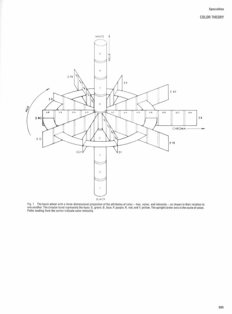
Specialties
COLOR THEORY
Fig. 1
The basic wheel with a three-dimensional projection of the attributes of color-hue, value, and intensity-as shown in their relation tooneanother. The circular band represents the hues : G, green; B, blue ; P, purple ; R, red; and Y, yellow. The uprightcenter axis is the scale of value.Paths leading from the center indicate color intensity.

Specialties
COLOR THEORY
Color Schemes and Combinations
DIRECTIONS FOR USING COLOR COMBINATION CHARTSCOLOR WHEEL NUMBER 1 Illustrates color corabinotions In -blob the threeprimaries ore used together, or the three secondary colors, or three tertlery colors .The three points of each triangle link the colors used In this TRIAD COLORSCHEME . The rule for success is to use only one of them in o strong, bright tone,In small areas, with the other two In softened (or grayed) tones.COLOR WHEEL NUMBER 7 Illustrates the color pairs which are effective togetherthrough contrast . This Is called the COMPLEMENTARY COLOR SCHEME . As thearrows Indicate, the palms ore exactly opposite each other on the wheel oneshould be used In a bright tone for smatter areas, the other In grayed tones andlarger areas.COLOR WHEEL NUMBER 3 Illustrates the use of a color with the two which erenext to Its opposite on the wheel, one on each side . This SPLIT COMPLEMENTARYCOLOR SCHEME follows the rule for complementarles, and may Include the directcontrosl color also, If desired. For example, yellow may be used with blue-violet,and red-violet, with or without the true violet shade which comes between them .
1. DOMINANT OR CONTROLLING COLORDecide on your dominant or controlling color, which may dominate by cover.
Ing a targe area or by strength of color In a smatter area. Decide whetheryour foundation or background color Is to be the dominant or a secondary color.Pion to use a large amount of quiet background color, a small amount of bold,strong color. All targe foundation areas should be In tight or grayed tones.
2. GRAYINGClear colors are gayer, more cheerful, but grayed tones are more restful,
their harmonies more subtle . Mixing gray with bright colors brings them Intorelation with other colors In the room . Am . . . red and yellow In bright lanesseem to clash. Mixed with gray, they become rose and tan and go very welltogether . Use this principle also In buying materials . Avoid too much graying.It gives muddy tones, dirty grays, flat croons. A little gray goes far.
3. RELIEF AND CONTRAST COLORSDecide on relief and contrast colors and bring them Into all parts of the
room composition. Remember the order In the amount of space allowed eachone-loundalion, then relief, then contrast . All colors-Including backgroundcolors-should be keyed to the dominant color. Soften strong contrast colors
To avoid confusion, not all of the triangles are Indicated. Cut a piece of PaperThe size of the triangle and lay it with Ike top point at any color you choose . Theother points will most on the correct colors .COLOR WHEEL NUMBER 4 Illustrates how an ANALOGOUS COLOR SCHEME Isdeveloped by using colors which ore related because they are side by side an Mewheel. Any group can be used, all around the wheel, as Indicated by the dottedtines . For an accent color you can use a contrast color opposite any one of yeargroup. For Instance, In the yellow-orange to red group, complementary blue couldbe used for accent Ishown on color wheel 21 .Black, white, gray and other definitely neutral tones can be used with anycomblnation ofcolors.
BASIC PRINCIPLES FOR WORKING OUT A COLOR SCHEMEwith white. Contrast Is loop In tighter tints . Soften darker contrasts with grey,
4. ACCENT COLORSUse pure bright Intense colors only in accesseries, etc . Distribute them se
they wilt nor be spotty . The smaller the area the brighter the color may be .Thp larger the ores the mollet the tone should be. Don't use targe omounts etpure bright color .
S. KEYINGThis is another means of creating harmony. A key color is the one about
which the color scheme Is built-the dominant, or controlling color . Ali othercolors In the room must be "keyed" with It-harmonized . Two colors In whichany part of a third color Is present wilt be linked together. Example . To keyrod and yellow to each other, mix them both wish a little of IN. third primaryhus-blue. Yield and green will result, and these ore harmonious to use withyour strong tones. Remember this principle in buying as welt as mixing colors .A lovely print or art object wilt have these tones keyed for you, and you camuse them for your own compeslllon. The sale rule is to ovoid too many colorsand too strong tones except In accents, etc . Most colors will "go together Ityou soften them .
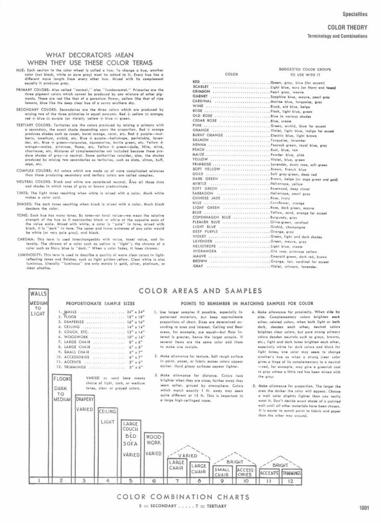
Specialties
COLOR THEORY
Terminology and Combinations
WHAT DECORATORS MEANWHEN THEY USE THESE COLOR TERMS
HUE . Each section in the color wheel Is called a hue . Ta change o bust, anothercolor not black, white or Pure gray) must be added to it. Every hue has adifferent wave length from every other hue . Mixed with Its complementequally it produces gray .
PRIMARY COLORS . Also called "normal," else "fundamental." Primaries are thethree plgment colon which cannot be produced by any mixture of other pig-ments . Them are red tike that of a geranium flower, yellow tike that of ripelemons, blue tike the deep clear hue of a sunny southern sky .
SECONDARY COLORS . Secondaries ore the three colors which are produced bymixing two of the three primaries In equal amounts Red + yellow = orange;red + blue = purple (or violat yellow + blue = green .
TERTIARY COLORS . Tertlories are the colors produced by mixing a primary witha secondary, the exact shade depending upon the proportion, Red + orangeproducer shades such as russet, burnt orange, coral, etc . Red +
purple-mul-berry, amethyst, orchid,etc.Blue + purple-hellolrope, periwinkle,laven-der, etc . Blue + green-lurquotm, aquamarine, bottle green, etc. Yellow +arcnge-molae, primrose, flame etc . Yellow + green-lode, Nile, olive,chartreuse, etc . Mixtures of complem.ntorles not Included because them pro-duce shades of gray- neutral . Some authorities conoldor aim, the shadesproduced by mixing Iwo secandarles as lortlarles, ouch as state, citron, buff,most, etc.
COMPLEX COLORS . All colors which are made up of more complicated mixturesthan those producing secondary and tertlory colors are called complex.
NEUTRAL COLORS . Black and white are considered neutral . also all those tintsand hades in which tones of gray or brawn predarnlnate .
TINTS, The tight toner resulting when white Is mixed with a color. Much whitemakes a color cold .
SHADES, The dark tones resulting when black is mixed with a color. Much blockdeadens the color .
TONE . Each hue has many tones. By tone-or tonal value-we mean the relativestrength of the hue as it approaches black or while at the opposite and, ofthe value scale. Mixed with whit ., a color Is "pale" In loner mixed withblack, it is "dark" In too* . The upper and tower extremes of any color wouldbe while (or very pole gray), and black.
CHROMA, This term Is used Interchangeably with value, tonal valu., and In-tensity . The chromo of a color such as yellow Is "light-, the chroma of acolor such as Navy blue Is "dark ." When a color fados, It loser chroma .
LUMINOSITYi This term Is used ta describe o quality of warm clear colors In light .reflecting tones and finIshes, such as tight golden-yellow . Clear whit. Is alsoluminous. Literally "luminous" are only metals In gold, silver, platinum, orclear Plastics .
SUGGESTED COLOR GROUPSCOLOR
TO USE WITH IT
RED
. . . . . . . . . . . . . . . . . . . . . . . . . . . . . . . . Grwn, gray,
blue (for occontSCARLET . . . . .,-,--,-- � - � ,- ��� ,Light blue, ecru (or Navy and )steps/CRIMSON . . . . . . . . . . . . . . . . . . . . . . . . . . .Pearl .cry, mauveGARNET . . . . . . . . . . . . . . . . . . . . . . . . . . . .Sapphire blue, mauve, pearlgrayCARDINAL
. . . . . . . . . . . . . . . . . . . . . . . . . . Morlrse blue, turquoise, $sayWINE . . . . . . . . . . . . . . ���� . �� --,Black, old blue, belgeROSE . . . . . . . . . . . . . . . . . � . � . ���� Flesh, light blue, greenOLD ROSE . . . . . . . . . . . . . . . . . . . . . . . . . . Blue In various shadesCEDAR ROSE . . . . . . . . . . . . . . . . . . . . . . . . Btu-, aeonsPINK . . . . . . . . ., . �� -,-, .--,- � - �� Green, orchid, blue for accentORANGE . . . . . . � - � -,- �� ,-- ��� Violet, tight blue, Indigo for accentBURNT ORANGE . . . . . . . . . . . . . . . . . . . .,Electric blue, tight brownSALMON . . . . . . . . . . ., ., . � -,- � -,----Turquoise, lavenderHENNA . . . . . . . . . . . . . . . ., . . � , . . � ,- .Peacock green, royal blue, grayPEACH . . . . . . . . . . . . . . . . . . . . . . . . . . . . . .Rust, blue, tanMAIZE . . . . . . . . . . . . . . . . . . . . . . . . . . . . . .Powder blue, pinkYELLOW . . . . . ., . . . . . . . . . . . . . . . . . . . . .Violet, blue, greenPRIMROSE . . . . . . . . . . . . . . . . . . . . . . . . . . .lavender, dusty rose, soft greenSOFT YELLOW . . . . . . . . . . . . . . . . . . . . . .Brown, French blueGOLD . . . . . . . . . . . . . . . . . . . . . . . . . . . . . .Soft gray-green deep redDARK GREEN
. . . . . . . . . . . . . . . . . . . . . . . Brown, beige (or sop. green and gold
MYRTLE . . . . . . . . . . . . . . . . . . . . . . . . . . . .Heliotrope, yellowSOFT GREEN . . . . . . . . . . . . . . . . . . . . . . .Rosewood, deep victorTARRAGON . . . . . . . . . . . . . . . . . . . . . . . . .Heliotrope, pearl grayCHINESE JADE . . . . . . . . . . . . . . . . . . . . . .Ross, IvoryNILE . . . . . . . . . . . . . . . . . . . . . . . . . . . . . . .Cornflower, orangeLIGHT GREEN . . . . . . . . . . . . . . . . . . . . . .Rose, dark green, mauveBLUE . . . . . . . . . . . . . . . . . . . . . . . . . . . . . . .Yellow, sand, orange far accostCOPENHAGEN
BLUE
. . . . . . . . . . . . . . . . . Burgundy, grayFLEMISH
BLUE
. . . . . . . . . . . . . . . . . . . . . . Olive-green, cardinalLIGHT BLUE . . . . . . . . . . . . . . . . . . . . . . . .Orchid, champagneDEEP PURPLE . . . . . . . . . . . . . . . . . . . . . . .Orong ., grayVIOLET . . . . . . . . . . . . . . . . . . . . . . . . . . . . .Green, Ilghi and dark sgadosLAVENDER . . . . . . . . . . . . . . . . . . . . . . . . . .Green, mauve, grayHELIOTROPE . . . . . . . . . . . . . . . . . . . . . . . .Light blue, creamHYDRANGEA
. . . . . . . . . . . . . . . . . . . . . . .Old as., primrose yellowMAUVE . . . . . . . . . . . . . . . . . . . . . . . . . . . . .Emerald green, dark red, brownBROWN
. . . . . . . . . . . . . . . . . . . . . . . . . . . . Orono*, tan, cardinal for accentGRAY . . . . . . . . . . . . . . . . . . . . . . . . . ., ., .Violet, crimson, lavender .
COLOR AREAS AND SAMPLES
2 .
a .
POINTS TO REMEMBER IN MATCHING SAMPLES FOR COLOR
Use larger Mol if passible, especially Inpatterned materials, but keep appr.almaleIl of chart . Sises are determined os-cording tg area and Inierest . Colline and floorareas, for example, are equal-bur Boor interestteerealer,hancethelargo".Pt..If
several Items are the some color add themlo mote on* sample
Make allowance for texture . Soft rough surfaceIn point, paper, or fabric makes colors appeardarker . Hard glossy surfaces appear tighter .
Make allowance far distance . Colors tookbrighter when they are close ; farther away theyseem softer, grayed by atmosphere . Colorswhich match *..city 1 ft . away may seemquite different at IS it . This Is Important Ina targe high-cellIngod room .
S .
Make allowance for proximity . When side byside, Complementary colors brighten eachother) related colors, when both tight or bothdark, deaden each cher) nautral colorsbrighlon clear colors, but pure strong primarycolors deaden neutrals such as grays, browns,arc .) tight and dark lanes brighten each other,especially while for dark colors and black farlight tones) one color may seem ta changeanother'& hue as when a strong clear colorgives a tinge of Its complementary to a neutral--red, for example, may give a g .... ish coastto aroy unless a little red has be.. mixed withthe pray .
Make allowance for proportion . The larger thearea the darker the color will appear . Ch-ma watt color slightly lighter than you realtywant It . Don't decide exact shade of o paintedwatt until all other materials have been chosen .It Is sasl.r to match paint to fabric and pape,than the other way around .

Specialties
COLORTHEORY
Munsell System of Color
One of the best-known and widely re-spected systems of color standardizationused in the United States today is thatdeveloped by Albert H . Munsell. He becamegreatly interested in the practical applicationof colorand was disturbed bythe fact that thepopular names for colors did not describethem adequately for professional purposes .They are named after flowers or plants, suchas violet, indigo, old rose, primrose ; afterfruits, such as peach, pomegranate, grape,avocado, plum ; after places such as frenchblue, naples yellow, or prussian blue ; or afterpersons, such as Davy's gray or Hooker'sgreen .
Essentially the system consists of an or-derly arrangement of colors in the shape of athree-dimensional color solid . The system isbased on a color circle of ten major huesmade up of five principal hues, red, yellow,green, blue, and purple, and five intermediatehues, yellow-red, green-yellow, blue-green,purple-blue, and red-purple . Each hue isindicated by a symbol as follows:
Red : RYellow : YGreen : GBlue : BPurple : PYellow-red : YRGreen-yellow : GYBlue-green : BG
Purple-blue :PBRed-purple : RP
Each of the above major hues has beengiven a value of 5 in the inner scale aroundthe hue circle (see Fig. 2, hue symbols), i .e .,5R,5YR,5Y,5GY,5G,5BG,5B,5PB,6Pand 5 RP Between each of the major huesare values of 2.5, 10, and 7 .5 for roughindication of hue . The outer scale of the huecircuit is divided into 100 segments to pro-vide greater accuracy for indicating huewhere needed .
In the Munsell color tree each hue (H) isallotted ten segments of the hue circle,making 100 hues, and these hues form thehorizontal center, or equator, of the colorsolid. The center segment of each color isconsidered the true color, and the remainingsegments in each hue section vary accordingto their proximity to adjoining colors ; forexample, as red gets closer to yellow itcontains more yellow, and this is indicated bythe numerical designation .The value (V) notation denotes the light-
ness or darkness of a hue, which is deter-mined by a neutral core at the center of thehue circle . The core contains ten gradationsfrom a supposedly perfect white (one having100 percent reflectance) at the top to 0, aperfect black (having 0 percent reflectance)at the bottom .The chroma (C) notation indicates the
saturation of the hue, or the strength of thecolor. The chroma scale extends outwardfrom the central core or axis, and the incre-ments vary from 0 at a neutral gray to as highas 16, according to the amount of saturationproduced by a given hue at a given valuelevel. Since colors vary in chroma, or satura-tion, some colors extend farther from theneutral axis than others, and the solid istherefore not symmetrical, Pure red, with achroma of 14, for instance, extends fartherthan blue-green, with a chroma of only 6 (seeFig. 1) .A Munsell notation indicating hue, value,
and chroma (H V/C) might be given asfollows :
Vermilion : 5R 5/14Rose : 5R 5/4
With this information it is possible todescribe exactly any given hue and to locateits place in the color solid. Furthermore, asMunsell stated, one can "select one familiarcolor, and study what others will combinewith it to please the eye;" by the use of threetypical paths: one vertical, with rapid changeof value ; another lateral, with rapid change ofhue; and a third, inward, through the neutralcenter, to seek out the opposite color field. Allother paths are combined by two or three ofthese typical directions in the color solid.

Specialties
COLOR THEORY
Color Families : Red
S w ô3 !
i ,e° ° ov-~~ ô 3 ~j ô éû .°., ô3gôE~Lôëj jj ~ ° _c ô â Éï `c TiY
â .B 3i
"cE~ a
ô1 e c°_
i
°"
E$Eô
° és
-!
oX
c Ei" ° o â c v
c . v 'i E é
ôa _
jE
E é > â E 'ô ô
C ~ C G $ e .û G C
9 E i û Ô ° O E O~ ~ ~~ c ~ O
ô ô -a-°E 8_ " â
.E w ~ â z Z ô 'E â
ww ~ ~ > r. Ô oT. . p
s . O
w
g GL
é.é `o . 3
É$ ~~ 3 " ôôe ô
Zd
~ ~û0 é
ôvi
j $ -CoO
$ . ` â M,2_
< Û = éOû
mw
jÛ
ôÛ
Ço é
li r eE .
~$svv
8 .àsSiOa
O ° 3 (!N i m m in in s ° m U m
é E $ â " ô Y c 8 c " cw c
> w
" s .2$
c 3 $ - ô c $ cW ô~ " -E c ~ ~ ~ ~é e ° ° ° $ é rp û
°i i s O $ Ô O X IL O 3 ° T w â ° a
Wm
CZ
V3 i2
~e 4-
~c ô
~ ~E . Ô- Ôâ s
i v c p ~o ~ôV
ix ' K É W C t 2" C 3 CO
ôô ~w~ w 3 ° ° i ° i $ t ô Q ô °r ! .°^ 3 C $ $ a'" ° gâ s $$ .r v' .: a g o é o r â g _ v ° ô gn
yf.a~ : 3" e :,
WW
i ix i °
w e ûrP° çs°°°a=3 aôon ; oôôv
! Sû ôn
vâ v É~n ~û"
E= O S - v G 7 O Uâ C 7 Z O , C7 0 3 p ô O O S CHiZ ~ô
H = ~ y ô OL " Yc-.~ ° w
y .o w
Otr OV _ g
Wip . �
WOO gr _ !
" ~û . â~ H O ~ ~e
m O é ~ $ 'oâ O t"
u. ô S d o. w c ~ c c ° u ~ ~ 3 É
NO ~E3 v Çs wo c ô-
~wO .û cûY~ "`o_
sOO ô
°E0L°
."O `ce
V br $ C" " °
ONK
'.Ô Y
~ ` E 7 w ink
8
c$ y ite$K O
$°°[ °
EO
em ty ; " v i _ lon i v v E ro ô
wcO û Z " ô N i > c O 3 O < c ï O w s° N
zw8 > Ô ow V W
!.2 .wN "i V
àéF ~E ` Ô Ô
H« K Y
Y
Z 2YZL
WO N W
WN0,
~
N
HN
..
OwiV 3_
Ô i d O < G W OC ~ ^ V O Y N N NV Z
OW SE'EG=
WW
YF' la= _ =..WN WN WN N N Q Q G
N JE d V > 0 G J K a 0 12 0

Specialties
COLOR THEORY
Color Families : Red
â
Éé ô
e e ° â - va s EE
É
_iû E $
E _ s 8 Eé = `â
j $ E$ ô
Z cc .y " ôo ~ ~ $
` P o _- oE
°
c o ô.2=
c$
Es ô
3`
-'~ E
$° Y
3 É $ °_ E Z li â ô
>_ â
ô ç ° E a ° ~ e E '3 - E _ o É ~ "~"w cP °c
< _ "~ v ° e _° _° ôô
o ôn Y n É
J-, E$
�°, 8 E __ Z n = d E _ .2 ° ô é ô ô é
U' V W Z m E " 3 < < U' V f U < ~O A c < 3 ü~ l7
iû
v "e ôim
s
ô
$ $ o $ e -° ° ` v $ i _v $ i v e 3 â v c3
0 m3 0 m r N 3 ° 0 - 0 ;~, ci ü û t> m ° u û 3 ü
$
P
É ~ ~ô
O
é éP ô ô c_ 3¢
é vô
âic $ E_ év~ o
ôc
âv ° â
ô c ô c ô ° ° ~°. ô ô.e.3 ô ~ ô ô s ç, ~ô c
nn ~ v
ô$~ ~ _ é é
i0v $ E .
3 ô ô3
.3
.3 2
.3 o
.
Ec3
.S-ô _ ô .b é
E ` v "â E s ° " ° Y c "3 t_ Z ° ô x --2
w e ô â - c â °73a os _ â c
ô._ $ ° 0 c 3
g E~ v é o E - . w v ° v 3v
o po~ < ô .ô ô hiv é ~ ~ w 3 y "oao
°çc â ôv ~! ôvr
v ô Ç ° w °> é S â â n°72
° â â P `_ é ô ° _ ô n ô ô ô t o ` ° w ° ô c ô ôr â e e
i ô C â ô ô ô ô ô ô ° ô ô 0 ô ô é ô ô ô e ô ô ô c o ô o é ô i é o i o
_° "â~°s v o ~~o rn° "_ °r
n° °n~°r °< 2
8e $ô n n nto.c°` n
°so.
ne1°n
n â=û c`~
n o 0°c ô~
0.~~orn
3 `5n
c`nD c`=
nü2 °T
c ë~°n °. 1n
o D o M2 1n 2
o=u On2c
!w M
2 1nam
2 no, an
~n ~ = âc 8am
E o c°
e 9~
~ Vv O
P
Yv= ôV P ~ éK v c
° _~ É ~ v
~
v ô c a _va °°, F ô g ,j .4
c Y' c w °' U' ; ô
~0
~ Y a
L C S O . K C N Y G u V N u m m i 9 c C0 3 O A W K G m 0 m d
E 'O On° 9 O
Or°w
U
.Ôv
Y °Y
3oOâ
O 9ô ô
G Cû
Y
S .Y
â $ ~ - : o ~ 3 e ô s .-
p3
vvy i
uO
o = ô ôr n T
iO Ô Ô
n
w^
- at r ~ e ._ s
S 2.6 D. 3 0 3 Z 3 m N N Q (~ 0. .. ? C u d 0 N O. O V N 0 O. a0
H Q _
^_ N - - Z Q Y > 1 Y
_ Q Q Z Z Z W W W W W W Q S Q Z = Z Z
tz i g_ _Z d Oâ
= Z _7. W Q Q Q et Y w 0W W
mWas
Wm
O~�
O�,
09u acu =u _u
:~.. H
- u 3 3 3W
amWm Ô
>m m m a

Specialties
COLOR THEORYColor Familles : Orange
râ- ~° sd -
;Eg
; _â eo w
é- Wc
sv s a_g a =_ â
s "W ôo=
E
rWi cd
c __3
__ O
EpO
ô » $ E< el
o_'C O
ê
$ .~Q ô é é o v v E
ô c ` ~ <é° É c Eo
G o ° ) Z eo
ô ô ô ô o Û .~.â c ô
.E $ E ' ô co w .'. E ô » û e
° i . v ° c é c° _e e é fi ° E E ô � ç ° é _ 2 e c ,°, â
c Eâ° c w " V Ç
E w o°
iii
° _ _ e B W o = <_o o w o E o
°= û <
ô _ W û 8 i w.ou >
r.
oo û û <
oo
; n<
_ ôf u S
n< ûW
o :_c~ 3
ou
of
n<
; L`<
ô ôS ~z_s=
$ $ 0l- s
ôz 0.ô n p :e "`
zQ2
OO
O~"
c; o
éa
<â
v° ét _^ vO
V
Z é
r
uéû =
ô(9
o`o e
c $v
m
^ v < ot c3 E
EY
G
QWVV
o
ô
çeë:-
Z
v
`nô
3o é°
vc
Eoç
3C
<.nVo o_ c
-°°a. v
oe_
f7
c
u°
ceo ;
.
s
co é0
ô8 S Q m m O V
ôa c)
ou Ô < O m 9- 3 4- Vn O 3 e. m Ô m 3 Ô (9 in
c
.
Ës
.ô ôx~
;~
Yô
â o °- âé
»3
v °:E v
ô v°n
0. ô
on. o o
8v
-3â
W ô o â c â ë 2 , c ô° E
HY (J ô s° â ô ô - ô Ev Ç c °o É
û "ô 3
Z ' Q ô_° v E
W c'v é e ô
° v0 0 ô_ n â
0 o.
W UWON
dG
W
72:. Sv
<g ô .
Ôii
O O W, é
.Oô-
o v veô a.
° O~
ne
09 "c CEE °
T iûEE
vâo
n.. â0
Ç QN o Z. vo v ô v c -6ô sô o L _ô oôv ô ô °
ôa â
E 0 .1 '0" meW - o .~ a e e e t Ç:t:3 < c -
0° â
3< °N ô .E
x3ofG
o vc
° L.r
oâ_ °
On _ôOnon v _
ô ; Cc-o
°V
vô v â ` d ow û û m $< <
ôô
nc n0 e
ôe-n
ec°°
3
o.n .g r n n s n n c â n ô $
3 .8 t .n"`-
<0C
o n=
o0
o °Cn=
o ôm'v<
o 0G
`oU ô
0m
o n_
o0 ûv
oôn=
om
û=
°Ô ô n
m = Gn=
o0 °
aGn= m u
°a âm
rH
Û ôâoi
YN K ô °
CK éi
i oOOV
Ou
~O~ °
°~
°~ û
° 9° ô
O ; . O = w Yu .. o so é
E1 W ` o û V c e °W â ô °6 E 9 i o O. ,y 6 .~ O Ô G ° r
. Z u pC
U~C! Ô1 Ç. <
O(7
m _O
OE
m m 3 °Ç Ç L
.- Y °v W
a C âm e
m
W
m "Ws =
o*~ ei O 3 m` rc w nc < O 3 3 3 G x x w - rc ô O oo. a ei 3 3 3 O O
W < Eô ô o .-
Zô
. 9 w. St. ~ccO ; .3
cÔ ô Ô
y Ôn ocpG
' E- 2_< ô . t
3
Ou °= o
oço
L' W,nnoé
YC, i
ô n
S
m
on
3
_,°,
W
o cii=
c " 4 1"o 1 01 0
ô2 3 ô
3 -<ô3K
-+~ ve ôn
ô ôn
_a ô ~ â e.W "wa
<V V° û 0 3
Yô. 3o c
3~ 3: 3: z
-5 !2 os _
ôfx
<_
3
QZO
_N_iN
_V.
_Vf
_~O .%
_N
t9W
t9W
c)W
t)W
C1W =
FOU
-.~..
QO
OK OO1OOCOOL
ui0
0 u >- x..x
...x
~.x
.~x x v <
-~
<
m
î
m
i
m
:E
m
i
m
i Z Z <YW
Ki Z î f î îm
'
u<Wd
u4Wd
u-CWa.
u
Wd
u
Wd
u
Wd11dQ
acOu
ixOu
,~Q3
e[Q3
°9Q3
°cQ3
~Q3
Wx
Wx
°dWr-
Ou
Ou m
oaQ3
ec
3
m
3QsQ3

Specialties
COLOR THEORY
Color Families : Yellow
s
F
i
ô!!ô
.~
É
Eô ô
éeéô
E
0 é ôvE$ p
vc°
3 $c
câEô
L â t c
c
ÉE
o _. .ôou E E
.6 "eé
t , K eE
6E
fi
`o
ââ
.3E
EE r
f
uv~
e= Eo
rv°
G. E-.
é
v
ôc'î 's
E E
i .. v 8 ë É ° E - ô ô _3
s "É E w
Eô ô c
= ô, E vY o E _ '= ô = ~_ ô .21_ i é _ E c
É-c 2
w c E ; o0
o .ô $ ô o e c é°" t W < V" V , ui V < V U~ < N V
ô 9.I -c ° o
ôé,c 9 Z o~tZ
°f ô ô. Q
OJ$
°' B Y' e
s cQ
°Y$ ;c
" se O
Q û =
fe
â
K
°
(!
8 â
pe
° $ uqYô e
S Y f _° é'Y Q Ô cf û 3 Ô v 3 - ô - Ô 3 u ~, w Ô ûT
O O . e O.
S Z !Ô E
Ô W OC . l C
é c. ô O ë4 1. 0
_
0
W w . uo ~-ô
r .63O
YW
u
$ cc.3 v
uâ
z ~ 1- tia
e
û t~ OW
Ox 11
a g0 3 ée.â i
e
.3é
o~e O "Eç
ç ôô~°, E E
t :ç
.3vé
é
" Er
.
ût ô ô
LLA z L."$ vc $ -°T
3t} S âô W c
c c
S Eos z ~£ cc s10
~ô ô : ô : é :
a 75 K -6 'a -6 C
T 8~ CN 6» 6~ o~ m o cû c n~ c~ ~~ o~ u m N
ôm Ev E
s` c1K0
O0 Soy , "
E UOW
O Eôô e
u sHc â W
OWv
°°o ô m é 8
Oé~
3 8r
zO
O m r m C 3 m O C
X .0 .0 0
ôâ°~ gw
s~r3
,3su c ° 08r O é c v ;
W m E ` ô +OU
câ û ° â
! mQ : Èg Z ;
JQ3
E
3 ô
Ot 3 30 3o
Ô nm 8a " v
3°° 3o c p
.Y pç
OQ
Ô
8ô c
°
o
31-2
oE
â °ô_N
.ô ô ô ôÔy
âû .`â . E
Ô T
_e
T
ô
e~
°Q u Ô
pZ ° V 3 m ô> ôL LÔ O °1 ° °ôN â
N° ° ô ~ 'n °â~ ôN °N V i âN
8_ _G~ F
= z ô ô ô 3 ôN z
z3O
30
° z
" ~= N M Q Y3
Y Y
O
Yu 3
_
Oiû Q ~ WYW
_~W
J~30O
~30O
30
30
30
30
°Y
W°°O.
z2
z0 s
KU a0 Q~ Qp. m . QD. O W
~ YO W~ Y
WY
WY
WY
WY
OL('J 0 W
_FV ~ N

Specialties
COLOR THEORY
Color Families : Yellow
ô 0
t` 2 Çô
ô ° := â
ë éc
E __v E
< : = ô W E S
O!E
"ErX
r3Eô
E$
W
t2a
e
$W wc c~,
.
â "in
"
ô
';°?
E E
Eô
ûâ
a
t'Eç
.5
É
Eg E
ô
avc
$ "E ° 3
Eô c ,°, -°
gc
ô°
eyo
8 rô 0
é0
_v
ô " âé
Xc
$ 5 0 - C_E E E c
v eS o
eE
g'vCc
c
v
é
8oéï
i â E L OE n ô 0" N u ~ N
c ô â $
v
$üc
°
U 3 0 "
vô s_
3~ s
a o
u~
° ô "
s
é
m
_YU a
W m o°e m m N ; U i r" w 1 Y m > 3 U i 3
-ay c
Wôé
ëv
â
O
r 5
9 "
8
9 G
ç
C
, 3
c BEE
$ôe ~ s_
â° é° Ç
$
çYc"~
So_
~ô "
Yôv
i
ô ôo c
r É ° l $ ô a°, s ° ° c$ é ° d : $
é3
v_âv- ô
c_i ë
°°0ô
`°
° _i é c . û ô
v
°
"
e°n
3 é
.2é °rc�
û'ô
gôc°
ô E
c ac_ ô
ô â
ca
Y ii0 â
c�
=
. é
u_ E_;
c3
â9 t3
cc o
âs gn
07c_
ôinO~
ôrn0~
1 -6n07
cinO ~
,3 °n
0~ SIffô0
a °° p07
â_ ôc$ -
'°O
.S ô? ôO >
0
>C"I
.& ô~n0:)
$ô~ GO n 15
Er
é_
S mOL°
07
°nG=n
07
`oOV
.ô.û
O~
$0°S07
SC
û$ô°pO'
T i
V G Oa
v$3
o
ôu
yv~ $a
a
°
ôéé
Oô ôâ
°
oWmEô
om`
âÇ
°ûô
Z
3om $ u
c cû
m 00 ôOx
O0 _ °m` . .$ É
°ô
Cd
~Om
$=
° b=o 0
iu
G Ou
G~
Wm°
w
~û
Y
ç
~[
8
:n
3
ën°
c o a o
O o c o 3 vcc_ .%
i> É
0 o E om
- ; m Wi
3
O uV
. ô
â30
a.
() Z ô ô3t0m
cÔ
o Eô3
Yc o
V
o
N
osN
3°
31°-
r
Y
m`
Zâti°"
oV
sW
3Q 0-
&_ _ =3 3 ° ° Z W 3 3
WC
H
_
CJQU'
OQu
ZY-
_
Z
=
2
Fa-
?
ZH
3
Qm
0m
2X0m
Z Z3l: 30 0O m
mJmh
mJm
h
Z ZN 3W
V0m
Z W
3G
H (9
m
2
uZ
a 3m Q
pft"
ÔU00Q
32
U on0
mYm
0
m ZY 3
Q0 Ô

Specialties
COLOR THEORY
COIDrFamilies : Green
t
8° 0 8E- û Eé ?_ L ô a
°= o ~
i~°
Eg
E
ôEé
ô~ oE
80
3
= ôe "Y g = $c ô
â_Eô
É£
é° f" _
c ô é :E .0 0 "s S
ô " ô "ô ô w é ôY
ôô ~ ° ô
E
û �~°. ô c° > E c E é c X
Ée ° g ô v ° $ N c
°
oâ _
>.°
cw E
ET
V do `c! E° °ô ip = Ç Ô
â<
$W
ôG
_<
c°V
ôli
_H
_W O"L < W
é~
$
<
E
OÔ - Ô
Ô -7
.
.°.EÔ_
v-
OL
ZÔS
v ô 3 ô °Ô
Pw°.GG
O'- Ç
Q_Z:E
ZW Oû ô
o>C
3O
_3L i 'S
YL .
' f.
âig
C ÇW 0
<
Q Vi
U°
3Oi
°3 ô vp
>
.Ym°c
ô O.0
e
~E~
Yô
t
-°m V O 2 O â m
ô.
° sû n j ` â Z $ c â
_J
° ~E
0
'Ov oyÔ Ô~
~
W>~
~'
Ô
v ô° ~
Ôôs
vÔ
côC ô
'cyÔ Y C> Ô
3ç ô
ô $ B=Ë
3 ,
W sa
°~eWe
CZQ
oY
ô c8°
3Yé
°
`m-
;c
°û
`Y ~Ez. $
°
o
évô
c= °
3 véô
c $° vmôt .2
0 Eô c cÉ
W:ES
WW
ôae2 ~-°,
v_c
°°
vrô"3 â
é°g° m
°vc
c ôe=û ~°.
i a~~ °Y 3g -°oé 3 ô_- r
W °
kç ~~U3
QG
; â cec~v° ~'ôn
o `
3â;c .û
$e v
ûô
vô
c `cc$ô
É ô Ep ~ô
° v~â
` °w°
û "â$
`°
cv`L é._ o
E -2é e. _ » ô » ô
wc.~
toP ô ._ Z nM ô ô S S ôp 'i Z= 'é
:Z â
n. W à . S^û8n
gô ôâ âû" " i É W O ° O ° 7 O O O N p 7 U G ! D' E 7 7 Ô O 7 7
~V o ô é
E -.o _Se ,.s>°
0ô
û
OL
Ou
E ' Y ç=_ 9 F. O O 3
z ' O OÉ " i
_e "
CiOâ
OY E
(!r
Or _~ E
3?
a O
â
O
giU
OE
e Es O i - oN d >i_:
o[ O O -0>
r
~W Î ~r
w~ é "é E0
_m' =
C1i
ôm '8e-=
Q3
ô
N ° .W
.. U LÔ L
_ _OO
OO
T 7_
"w °w O ô QO O
°:a
°c
< O li �°, 0
O-~ONV Z :E 1 d O ` < L N N 1 N V O
~n 3<Z " w v = r - N .. . .~. . .N < U e ON K ~ " Q O
W < =
H
Q °~Z O
W W W W WY
WK
WK
WK
ZW
ZW
ZW
W= W
m u 3 p KU,
KO t9 t9 C9 O
WCl G9
9O W
eec
u
dJi
s
~
s s6Q
-6Q
J°"Q
>-O~n
Ov7
O~ O~
>>
6WO

Specialties
COLOR THEORY
Color Families : Green
ô $ É$â ~ $' S6 r s
EE c ô = p =
g_
E é E v
c°E$ `c.
S.ç
E
E ~ Eô
âw s
o_s. ô ô
; $ ô c ï 3
n ô : .°o " c Së
â° -.3 û .
`o g ô - w E E C~
é w w ~..°ç $ E
e°
PcY E
ô °~
=
eô.n ~
ô ôÉ.
__ .>_ ï
.3 c .
T _ ô ~ ô éE
$
é _ce c
_ _° ° v a E v ~ $
o°- _ ~ Yc
$°E
ôw ô ô
C" ia=
côE
_
-
oo w
ô'v S â
E ~ ~E_e a
° O O .°r w S ~ 0 V S3 1 .0 c. c.
û Pâ c
S°~
âo
i= e- ô :w_ o ç g
E$ °c
og
$û
c E ê
1c â -° r j e
V < < W 0 f < < > >_O N N i > ti i > N V U 8
° â üc°Ô
$lj
va
vc°
éo
U 3 N N H N h K m C K U~ 3 } N 3 U m U
9OOr
~P-
T°p
e p ô" p $ ~ O
$ 8 8
ô n d $ a 8$ c ü
o
t an i ô â v w Z : ô $ $
° ôô -
1 $ ûo2 2 76
o;
°'-
°$
ô °°v
Yu E c
âé ô û Q `o oE
c $û r v
3âvô
°o3
vô
vô°
ô °°
$°
c $
=ôeô
E c e ô = â $ =
f_ ôô â
r â :~ ô .n 3 ~ ._.3 $ w c û.
3c ° $ _â
3' û n ° v .'v ~ w c n c ` é 'o ô E -° i .3 C
c° °3 ô "'- b= yû 1 E
r$éc ,°, °Z u ., 3 âc co rr u° cP » 3 o vo=
$ ô ~ ° é Z ô a â é â ~ a ~ e » ô e o' ô M ô : r ô e â ~ i w é e
li é ? ô °o
$.`oc =°c ô °
�
r 0 ._ ô o r ° r ° c° °v ô c° ô r ô c° ô r É
c`7c°
V' () ~~ U G1° 1°
< 02OM,
° 293M 3 ° G7
2051
2G5
2G7 0 a 0 5 05
L ô .3
ô cô ô
e 2 ~Sü
E 3 em
°c
$ü
$é
v $S °
$ü
$ü
c=~
$ $ü ôN
$ü
ôm
eü
$ü
$ü ô$~ 3 e
V' .-v l+ O N m i° V if m m ô~ â m` l1 O G G Ô ~°- e~t
ô 5°û
o û e° $
.3ô 0 "i E
^U 3
ô û ~a ô`e c a. i
ô6
P Y
3 3 ôôü <
»v
? $û
$ü
$ É $ü
vco c
ol)
$ü
°O $
ü0
m
... ,~. _ WW_ N_ Pl ~_ _Y !V l7
WZW
ZW
W W>
W>
ZW
ZW
ZW
ZW
Z Z Z ZW Z
WW WWWW
>
U, V C9W
WH
FM W
mF°~ W
_NO= l! 9 t
W<J
cct9
WeeU'
WecU'
W.tiU'
eeU'
<C9 Z
Ytl
Y
C!Z
z
F~Zî
WO 0
0< Wûno
Q WU~
O W
m
W
m
W
mW3
yW11
dWc
dWô
e.Wc
LWô
OWW
i»
Kô
29ç n
WW
1 01

Specialties
COLOR THEORY
Color Families : Blue
3 t3
g .a a e a_ Q s
3E é =
L's .. ' V1~
3â
wr
ô.g
E
s
)
ôâ°_
.Itc ~ s aE 21 g _
1E 1. o ° E Eô
aô ~ o
_ ô 4:E
it
E
s
c EX X .°.s
B_'-"e
3E°
ë' .
pô_
iÉ ._ 'v
êvEa E ° E 0 »
-
é 0
o
o ";ô
E
v
w
E=~ l;s ô° 8 â ~ =
.~8 8
a g .1
Yo ' ôf v o t~ < i t9 0_- is ï .X
a "~ ôC -Eéâ 0. N
" y° i é O 3_
Q O é
.Eë
SÔ
Z
g~
V
5: O
°
â
-N
-EE
ô ' `
c
QUQ
i
w
,s,
0
;
0
L9
a
=
v 0
0 â-
`o
mc ~
q
b
1E
sr g
E°
G
J
c
8_ ô g
vô
.g
GC
.EE °o
â.T
E
.o .
O _Ô Z E JH
0
ô
_Ôô
v
°ô
i MOu ~
0
ufj
°
_
"
_
;°
e
é" n
°;
vô °
E
.3 sv
e
S
W Wd
C2 é ô
ic . .
-`3 3t a E _;°
.`E
3 °c °
_°3
_~ Wf
MW
°sn
Ô Ô ° °E 3 _v a ..
P~ vc
ÔO
i;
YJ W é
ôû
°i v tii
v
°
EsJ S ? ° a°. s
a° n° v
Y ûro ; É .
É
" ? gn
"" ~ v ûéô
côô ô ô ô é
s I"s
v .ô _ E2 1. é ~ . 2 ?ô» 2'. ii rn 2 0
3
ii
' O O W ~- U G n 3 07 Z m 4 G ô G7 0c U u' ô
. ,v Km
; s aY
s_ ô ôOU V
Kôs
8e C
F00 ÔÔ
v
$= E hW
C ~m rY °
E ic$
"
0~v~
0~1m o°
n mm
v°
âtj
v° (9 i
m `o
_
v_âm
._
â ô `oo
Q
C U
""
°P °d
°
ad m
e
0m
ô n
-uô ôo
n
W
nôo
u
m
c
id
âgE
$ $Oe
ûô c
°m ~ a
r�É
" ô V ~â
u ~ m
O .vs f 3 ? i $ e ° 16c 9 - m T
W Om __Z .
O
Qm
~
ô
m
ô
m
v
m~
m~
iâ
Ô n~ °m n m
o
;
é ° °
°v`
_
Ôm
Ôc°
Oa
î O
"" V Z
o
i
v
ilo,;
c°
Y e
d '-
v°o _
N _ 3
"
â 2
â
V
°E
s
_~~< :_Ç
_
W Z d H
2
Z
a0
~ ~ ~
m mQW
QW
W W
u â
Q j
Qd
x-
0d
'Od
Y W
m
Y W
~ 0
W
m
W
m
W ~ W
x
~ W
m
°1 W0-0
~%Z
m o x u 0-

Specialties
COLOR THEORYColor Families : Blue
I!r.r s
s `_- a8
ô E ~ s
sm S é ~v$ s v ; ô
E$ E E
E~
.é ô P
a âan ç
a. d j ~ $ 3 ~ ï ô E éôE
iE$ â
é ë'v
E$ $
ô=
g ô i ôE
c°côé
i
é$ T
S! é
;E
sm
° I? °mi E e 0 = W ç v -
"3E v .
E
E ~ $ c ô cv
É ç cPc
$ Eâ
E$ °
°
v ° i jv E6 âE
é_v°E
$"° ~ é â É $ ô -° $
vôc c3
U C < O w O F < 11 U U U = O 0
Sp
LO
Y (J y°
ÔCÔ
Om 9
17L N
$p
OK O
_v $ v° Z $ ôs
i i > é < u $ s iK v 0 0 K N N N < U~ iÔ m
Y4
P Y
OEs
-ca
C
> E . ar g _; °
21
v â ô ~ e a $ $ s â
E ô f r °ô
,OE, i v";
° vû ô
-vô
°i _$
s
E ôv_
v ; c "3 $ i sô ' ô â r
a0
s3
y=éé v E'~
3 k ta°. 0* E _ _id $ r " °a°. ~3-3âg â
r c c °_
c ô û ô ô c i _a ô E s ` » r c o ôO Ô c Ô
S a i .2E
E*
a o +c
ô
.°8°
5ô é -~° ô N
873
ô P ô ô ô
.°°
ô é
.°1
fnéI
t: é e
ç~ -° W ô~ 1 2v-0 0
Y2ôD° 3 BD c`~°°
1v aU
io °°O D âM°° c`= c=2 <cU O`=U
c ; ôc°
> >" O 9$_°
°O~°
Qe c
F
3`
_~m
vEO C
-_ m m $ ~ b "n â $ r a > >m
.ô 72 m m O m m m m c.B
° mcO N $O
iiO r ° s-
c;- K ô
P.i uc
°mo
ô ôO méO
ôZ
âm C!
cP
mm s ~ r ;
_a s ô ~ _> > Y o o~ ~
.~a ô
._3 a
ôE m 3 m ô
°m
"m
éU O
r _v0
ü0
°i
iî0
ôU
°3 3
_v0 O i
°00 3.
ô0
°i
ôU
ô=
iU
.. j > > _ _
>r0
>Jm
7~1m
Wj
m
J W mm
_N
m
_NWIs
WJ
WJ
WJ
.~.W W W
Y
W
h
W0O°"
> > > Y 92 mGW
0J
0 l0Z
mr
OJ
m >O
>O
2m
JID am ZW d
W W WY O
Ya K
dK
WW
aY
aY Y L
WAW
6W
ILW GW0, Y
93 8 a H H 0 9OC du 00I 0 O G O 93 0 m 0

Specialties
COLOR THEORY
Color Familles : VIolevPurple
ôs
e c E
""E :
E$
Y
ô 3 Z $ $ô4 â ô e 3 ô
ô ô tn L ° cOO Q
.3 % "G Ç P v
.`o.. .. c K'E3 .._°~
E ii v ..° ô
c S .~c. ô ô
u° E
c ô " E=
.2y° E
_E E : E
CB > ~ o
"_ c ô3O e _
~` $ 3 t.G t
Z '° .°. éô r û ° ô ô
v " é $ $ E ~` e $ $ û $ é p
C O SO
OG C z
H
O O° x ô -6 0 Q 0 ° i é ô e
û ' fuf.
Vlv ô
Nv vc
mv P
ôeô ~ ~ é
OO
zW
ô ôé
ô ° ô ° Q
É ~' r' Q V ô $ v .~ ° oc
f ô d ôi ô Q
o w f 01. é C éYWÔ ' Ô
~ ûOv v
O_ 'Ü Nw L..7 "O
WF Ç r Ô
ço
Z O_ ei uN O .. = e
OU Oh ô ô .3 °
o 9 ' ; r ô
OC W zQ
r sc ô E$
É_ °s
°
" : X W u .s. ° 3 ° g ea c e â 1
> 0 3..c°v
VWy V ô
â°
.
ü s u ûç é°$ E i
-é i Z ° é ôô ' ° ô i i â i ô ve i Z
r3
Lai
F-Wz
VIi
°û ü ! 0 e. xe ~ f c~ c`~ c8~ oe~ É
>
TH°f 0 9
pyv O O A
O Ë ~ $ VVe[
°ô
û ; - v O E _!O 3 ° n
" E â _w
W
W
O
~
<.3 ° v r
ô
3 O Ox
K n O
v
v
°-_
;
e3
~rI .E
, E;'
OV
_~ v
v~
vô
S7 "FO. C J O O .U
3O VO ô < 3
°m - ~ = 3 O
V n 3ao
vô 3 T
°a.° - - gs
°ey'_-
"=
Z Ô o°d -1 n s ü Ô d i g o ô ô .n 3 aâ
u
zWO_ UD f F
<S
_ a °Z
NW W W
&O
_ H ÎiO rK U
V G_ CT.
zW zZ ZW
29HO
W>
W>
~O
H W W W W
9 9 s s s = f AE _ 5;1
IEI
IE d

Specialties
COLORTHEORYReflective Values; Safety Color Guides
TABLE 1
Reflective Values
Approx . percent ofCo l or
reflectionWhite, dull or flat
75-85White, gloss
85-90
Light tintsCream or eggshell
79Ivory
75Pale pink and pale yellow
75-80Light green, light blue, light orchid
70-75Soft pink, light peach
69Light beige, pale grey
70
Medium tonesApricot
56-62Pink
64Tan, yellow gold
55Light greys
35-50Medium turquoise
44Medium light blue
42Yellow green
45Old gold, pumpkin
34Rose
29
Deep tonesCocoa brown, mauve
24Medium green, medium blue
2120
Unsuitable dark colorsDark brown, dark grey
10-15Olive green
12Dark blue, blue green
5-10Forest green
7
Natural wood tonesBirch and beech
35-50Light maple
25-35Light oak
25-35Dark oak, cherry
10-15Redwood
10-15Bl ack walnut, mahogany
5-15
Recommended ceiling values should be in the range of 60-90% .Floor reflection values should be in the range of 15-35% . Overallreflection values of a room should be in the 35-60% range.
Safety Color GuidesPhysical hazards:
Red: Fire protection equipment and ap-paratus ; danger ; stop
Orange : Dangerous parts of movingmachinery
Yellow : Physical hazards that mightcause stumbling, falling, etc.
Green: Safety - first-aid dispensary orkits, stretchers, safety deluge showers, etc.
Blue : Caution against movement or useof equipment being worked on such aselevators, scaffolding, etc.
Black and White: Traffic direction,sanitation
Equipment in industrial plants :Red: Fire protection systems and
equipmentOrange : Dangerous materials, nonflam-
mable, such as acids, alkalis, toxic materials,gases, oxygen
Yellow: Dangerous materials, flamma-ble, such as fuel oil, gasoline, kerosene,alcohol, propane, butane, acetylene, hydro-gen, and solvent
Green : Safe materials, such as drinkingwater, service water, brine
Blue : Protective materialsViolet : Valuable materialsBlack: Electrical conduit

Specialties
COLOR THEORY
Color Effect
TABLE 2
Color Effects of White Fluorescent Lamps
Cool' Deluxe' Warmt Deluxet Soft White _--White Coot While White Warm White Daylight White Natural
Lamp appearance ; White White Yellowish Yellowish Bluish Pale Pinkish
effect on neutral white white white yellowish whitesurfaces while
Effect on Neutral to Neutral Warm Warm Very Moderately Warm,"atmosphere" moderately to coot warm pinkish
cool moderatelycool
Colors Orange, All Orange Red, orange, Green, Orange, Red,strengthened yellow, nearly yellow yellow, blur, yellow nr .u1ge
blue equal green__
- _Colors grayed Re None -Red, Blue Red, Red, Green .appre- green, orange green, blueciably blue blue
Remarks Blends Best over- Blends Excellent Us(wlly Usually re- Usually re-
with all color will, color ten- replaceable placeable placeablenatural rendition ; incan- dition ; with CW with (_)AI wills CWXdaylight simulates descent simulates or WW or WWX
natural tight incandewenldaylight light
Color Effects of Mercury and Filament 1.11111)5
Color-White Improscd Deluxe White
Mercury Mercury Mer(tin Mercury tilarnem
Lamp appearance ; Greenish Greenish Yellowish W111ty Yellowisheffect on neutral blue while white white while
surfaces
Effect on Very cool, Moderately Warm, Moderately Warm
"atmosphere" greenish cool, yellowlO cootgreenish
___
Colors Yellow, Yellow Yellow, Orange, Rod,strengthened green, green, green yellow, orange,
blue blue blue yellow__
-Colors grayed_-
Red_-Red, Blue Green Blue
orange orange
. .. . .Remarks Poor overall Color render Cotorronder- fsl, "Illv,lcolor ing often ing good ; colorrendering acceptable, compart " s rendering
hot nfrl cllual favorably111 all y "Nile with C -WXl11noelcenl fluore,(ent
Greater preference at higher levels .
i Greater preference at lower levels .

Specialties
WINDOW TREATMENTS
Window Types
Windows are available in many types, eachhaving advantages . The principal types aredouble-hung, casement, stationary, awning,and horizontal sliding . They may be made ofwood or metal . Heat loss through metalframes and sash is much greater thanthrough similar wood units. Glass blocksare sometimes used for admitting light inplaces where transparency or ventilation isnot required .
Insulated glass, used both for stationaryand moveable sash, consists of two or moresheets of spaced glass with hermetically-sealed edges. This type has more resistanceto heat loss than a single thickness and isoften used without a storm sash .Wood sash and door and window frames
should be made from a clear grade of all-heartwood stock of a decay resistant woodspecies or from wood which is given apreservative treatment . Species commonlyused include ponderosa and other pines, thecedars, cypress, redwood, and the spruces .
Double-Hung Windows
The double-hung window is perhaps themost familiar window type . It consists of anupper and lower sash that slide vertically inseparate grooves in the side jambs or in full-width metal weatherstripping . This type ofwindow provides a maximum face openingfor ventilation of one-half the total windowarea . Each sash is provided with springs,balances, or compression weatherstrippingto hold it in place in any location . Compres-sion weatherstripping, for example, preventsair infiltration, provides tension, and acts as acounterbalance ; several types allow the sashto be removed for easy painting or repair.Thejambs (sides and top of the frames) are
made of nominal 1-inch lumber, the widthprovides for use with dry-wall or plasteredinterior finish . Sills are made from nominal
2-inch lumber and sloped at about 3 in 12 forgood drainage . Sash are normally 13/8 inchesthick and wood combination storm andscreen windows are usually 1 1/8 inches thick.Sash may be divided into a number of
lights by small wood members called mun-tins. A ranch-type house may provide thebest appearance with top and bottom sashdivided into two horizontal lights . Acolonialor Cape Code house usually has each sashdivided into six or eight lights . Some manu-facturers provided preassembled dividerswhich snap in place over a single light,dividing it into six or eight lights . This sim-plifies painting and other maintenance.Assembled frames are placed in the rough
opening over strips of building paper putaround the perimeter to minimize air infiltra-tion . The frame is plumbed and nailed to sidestuds and header through the casings or theblind at the sides . Where nails are exposed,such as on the casing, use the corrosion-resistant type .
Hardware for double-hung windows in-cludes the sash lifts that are fastened to thebottom rail, although they are sometimeseliminated by providing a finger groove in therail . Other hardware consists of sash locks orfasteners located at the meeting rail . Theynot only lock the window, but draw the sashtogether to provide a "windtight" fit .
Double-hung windows can be arranged ina number of ways -as a single unit, doubled(or mullion) type, or in groups of three ormore . One or two double-hung windows oneach side of a large stationary insulatedwindow are often used to effect a windowwall . Such large openings must be framedwith headers large enough to carry roofloads.
Casement Windows
Casement windows consist of side-hingedsash, usually designed to swing outward
because this type can be made more weath-ertight than the inswinging style. Screensare located inside these outswinging win-dows and winter protection is obtained witha storm sash or by using insulated glass inthe sash . One advantage of the casementwindow over the double-hung type is thatthe entire window area can be opened forventilation .
Weatherstripping is also provided for thistype of window, and units are usually re-ceived from the factory entirely assembledwith hardware in place. Closing hardwareconsists of a rotary operator and sash lock .As in the double-hung units, casement sashcan be used in a number of ways -as a pair orin combinations of two or more pairs . Stylevariations are achieved by divided lights .Snap-in muntins provided a small, multiple-pane appearance for traditional styling .
Metal sash are sometimes used but, be-cause of low insulating value, should beinstalled carefully to prevent condensationand frosting on the interior surfaces duringcold weather. A full storm-window unit issometimes necessary to eliminate this prob-lem in cold climates .
Stationary Windows
Stationary windows used alone or in com-bination with double-hung or casement win-dows usually consist of a wood sash with alarge single light of insulated glass . They aredesigned to provide light, as well as forattractive appearance, and are fastened per-manently into the frame. Because of theirsize (sometimes 6 to 8 feet wide), 1 3/4-inch-thick sash is used to provide strength . Thethickness is usually required because of thethickness of the insulating glass.

Specialties
WINDOW TREATMENTSWindow Types

Specialties
WINDOW TREATMENTSWindow Types
DESCRIPTION
materials " wood, steel, aluminumuse " common in residences and apartments
operation " rotary crank or lever operators hold the vent open to desiredposition, up to 180°, but usually 90°
note ' available also as a single vent' generally allow exterior of glazing to be
cleaned from inside when outswinging ." provide 100 percent opening in.the ventila-
tion area" will be subject to wind pressures when opened .
TYPE
SIDE HINGED
CASEMENT
materials " wood, aluminumuse " especially appropriate for high-rise, life safety installations
operation " sophisticated hardwarenote " no protection from rain when open
' available to limited extent as "tilt and turn"type which acts as a bottom hung window in nor-mal use, but which can be converted by use ofsecondary hinges into a side-hung, inswingingtype, allowing for easy cleaning .
CASEMENT-HOPPER
materials " wood, aluminum, steel in varied quality gradesuse " commonly known as the "classroom window''
operation " combination of in-swinging hopper and out-swingingcasement vents offer flexibility for ventilation control
CASEMENT-COMBINATION
materials " wood, aluminum and steeluse " where vent will not interfere with interior conditions
" lower cost utility quality is commonly used for residentiabasements
note " no protection from rain when open
BOTTOM HI NGED
HOPPER

materials " wood, steel, aluminumuse " primarily for sunrooms, porches, and the like where protec-
tion from the weather is desired with maximum fresh airoperation " multiple vents combine unobstructed vision with controlled
ventilation" the louvers are fully adjustable and can be set in any position
note " can be fitted with storm sash on the inside to provide moreweather tightness
" screens, interchangeable with storm sash, are furnished" various types of glass, including obscure and colored, often
are used for pri vacy or decoration
materials
" steel or aluminumuse
"
medium quality grade is called ''intermediate
and iscommonly used in commercial, institutional and industrialtype buildings
"
architectural windows are frequently used for schools,hospitals, office buildings, etc .
operation
" similar to awning windows but with optional fixed glasslights andior hoppers
materials " wood, steel, aluminumuse " multiple assemblies are used mostly in steel for industrial
buildings" separate units are commonly combined with fixed lights, or
with hoppers for maximum stratification ventilation (These areavailable also in wood and aluminum .)
operation " are out-swinging projected windows that create a ''canopy'against rain penetration
" when in multiple, vertical stacks, the mechanical operationwill allow for the bottom vent to open before the other vents,which will then open in unison
DESCRIPTION
materials " steel, stainless steeluse " in commercial and industrial buildings where appearance is
not of major importance and resistance to forced entry is" to prevent forcible exit, sometimes called ''guard'' windows
operation " combined with fixed lights or with projecting vents above,which offer high and low openings that are best for natural-acirculation (due to principles of stratification)
" separate vent frames usually swing in as hoppers" jalousie-like vents also available" frames often reinforced with steel rods
notes " vents limited in size" muntins usually separate openings of 88 inches square
materials " steeluse " in housing for mental patients, to provide protection against
exit while minimizing appearance of restraintnote " vents have a maximum clear opening of about 6 inches
Specialties
WINDOW TREATMENTSWindow Types
TYPE
'_18OTTOM HINGED, continued
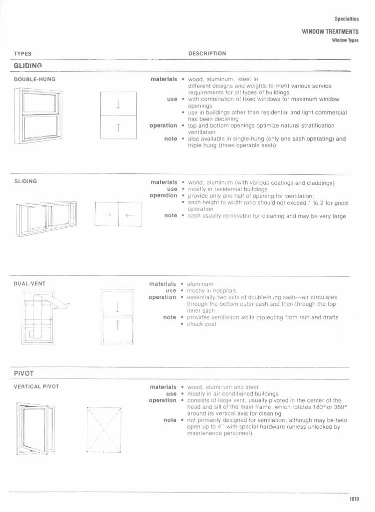
Specialties
WINDOW TREATMENTSWindow Types
DESCRIPTION
materials " wood, aluminum, steel indifferent designs and weights to meet various servicerequirements for all types of buildings
use " with combination of fixed windows for maximum windowopenings
" use in buildings other than residential and light commercialhas been declining
operation " top and bottom openings optimize natural stratificationventilation
note " also available in single-hung (only one sash operating) andtriple hung (three operable sash)
materials " wood, aluminum (with various coatings and claddings)use " mostly in residential buildings
operation
" provide only one half of opening for ventilation ;" sash height to width ratio should not exceed 1 to 2 for good
operationnote " sash usually removable for cleaning and may be very large
materials " aluminumuse " mostly in hospitals
operation " essentially two sets of double-hung sash---air circulatesthrough the bottom outer sash and then through the topinner sash
note " provides ventilation while protecting from rain and drafts" check cost
materials " wood, aluminum and steeluse " mostly in air conditioned buildings
operation " consists of large vent, usually pivoted in the center of thehead and sill of the main frame, which rotates 180° or 360°around its vertical axis for cleaning
note " not primarily designed for ventilation, although may be heldopen up to 4" with special hardware (unless unlocked bymaintenance personnel)
TYPES
GLIDING
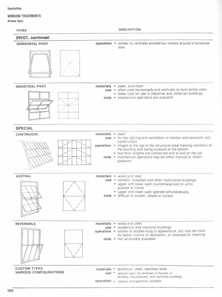
Specialties
WINDOW TREATMENTSWindow types
TYPES
PIVOT, continued
DESCRIPTION
operation " similar to vertically pivoted but rotates around a horizontalaxis
materials a steel, aluminumuse a often used horizontally and vertically to form entire walls
" lower cost for use in industrial and utilitarian buildingsnote " mechanical operators are available
materials a steeluse " for top lighting and ventilation in monitor and sawtooth roof
constructionoperation " hinged at the top to the structural-steel framing members of
the building and swing outward at the bottom" two-floor lengths are connected end to end on the job
note " mechanical operators may be either manual or motor-powered
materials " wood and steeluse " schools, hospitals and other institutional buildings
" upper and lower sash counterbalanced on armspivoted to frame
" upper and lower sash operate simultaneouslynote " difficult to screen, shade or curtain
materials " wood and steeluse " residential and industrial buildings
operation " similar to double-hung in appearance, but may be tiltedfor better control of ventilation, or reversed for cleaning
note " not universally available
materials ' aluminum, steel, stainless steeluse ' special types for windows in houses of
worship, mausoleums, and memorial buildingsoperation . various arrangements available

Specialties
WINDOW TREATMENTS
Window Types

Specialties
WINDOW TREATMENTS
Window types

Specialties
WINDOW TREATMENTSWindow Types : Projected and Stationary

Specialties
WINDOW TREATMENTSWindow Types : Double-Hung and Casement

Specialties
WINDOW TREATMENTS
Window types: Double-Hung and Casement

Specialties
WINDOW TREATMENTSWindow Types
Wood TrimThe casing around thewindow frames on theinterior of the house should be the samepattern as that used around the interior doorframes . Other trim which is used for adouble-hung window frame includes thesash stops, stool, and apron (Fig . 7A). An-other method of using trim around windowshas the entire opening enclosed with casing(Fig . 7B). The stool is then a filler memberbetween the bottom sash rail and the bottomcasing .The stool is the horizontal trim member
that laps the window sill and extends beyondthe casing at the sides, with each endnotched against the plastered wall . Theapron serves as a finish member below thestool . The window stool is the first piece ofwindow trim to be installed and is notchedand fitted against the edge of the jamb andthe plaster line, with the outside edge beingflush against the bottom rail of the windowsash (Fig . 7A). The stool is blind-nailed at theends so that the casing and the stop willcover the nailheads . Predrilling is usuallynecessary to prevent splitting . The stoolshould also be nailed at midpoint to the silland to the apron with finishing nails . Face-nailing to the sill is sometimes substituted orsupplemented with toenailing of the outeredge to the sill (Fig . 7A).The casing is applied and nailed as de-
scribed for doorframes, except that the inneredge is flush with the inner face of the jambsso that the stop will cover the joint betweenthe jamb and casing . The window stops arethen nailed to the jambs so that the windowsash slides smoothly. Channel-type weatherstripping often includes full-width metal sub-jambs into which the upper and lower sashslide, replacing the parting strip . Stops arelocated against these instead of the sash toprovide a small amount of pressure . Theapron is cut to a length equal to the outerwidth of the casing line (Fig . 7A). It is nailed tothe window sill and to the 2- by 4-inchframing sill below.When casing is used to finish the bottom
of the window frame as well as the sides andtop, the narrow stool butts against the sidewindow jamb . Casing is then mitered at thebottom corners (Fig . 7B) and nailed as pre-viously described .

Specialties
WINDOW TREATMENTSCurtains/Draperies
CURTAINSCurtains are soft window coverings thatgenerally are shirred (gathered onto a rod) orhave headings attached to solid-wood rods,round or oval metal rods, or café rods ratherthan cord-operated traverse rods . Curtainsmay be either stationary fabric panels or slidopen and closed by hand . They are flexible inthat they can be short or long, layered ortiered, or used alone or in combination withother soft, or with hard treatments . Curtain istraditionally a term for informal treatments,such as cafe curtains . However, curtains alsomay be quite formal, as are shirred andelegant tied-back fabric treatments .Even though curtains are generally
thought to be shirred treatments, other head-ings might be included in this categoryIndeed, there is a crossover of terminologybetween draperies and curtains . Generallydraperies are installed on cord-operated tra-verse rods, although they may be stationarypleated panels . Curtains may be installed ontraverse rods (as in a pleated café curtain, for
example), and headings such as the pencilpleat ; drawstring pencil pleat ; shirred,spaced pencil pleat ; alternate pencil pleat ;ruffled shirring tape heading ; and smockedheading may be called either curtain ordrapery treatments .
DRAPERIESDraperies are made with pleats . They arehung with drapery hoods onto carriers ofconventional, architectural, or decorative tra-verse rods or into the rings of wood rods orcafé curtain rods ; or they may thread ontospring-system traverse rods . Generally drap-eries are either hung straight to the floor ortied back . Thus they operate, or "draw," byopening and closing with a cord or a wand orby hand . The exception is tied-back drap-eries, which sometimes are let down atnight . However, tied-back draperies aretrained to tie back at an angle and thereforeshould not be handled to any extent . Drap-eries draw in a pair and meet in the center
(center-meet) or draw one way from left toright or from right to left . One-way drawdraperies require one-way traverse rods .
Draperies that hang at a doorway ratherthan at a window are called portières . Theymay be pleated in any fashion or shirred .They may be placed on a traverse rod, buthistorically (and they were used extensivelyin the Victorian era), they were tied-backstationary panels made of a heavy fabric thatwere let down when privacy or insulationwas needed .
Draperies can be made of any fabric . Theselection will depend on the style, use, andneeds . Sheer fabrics do best as diffusers ofglare and as providers of daytime privacy.Medium- to heavyweight fabrics are excel-lent choices for overdraperies and plaintieback draperies . Lining fabrics are the rightweight for privacy liners or underdraperies . Ifa drapery is given a ruffled edge or a banding,that trim should be a lightweight, semi-crisp,flexible fabric, not a heavy, stiff fabric or asheer, slippery fabric .

Specialties
WINDOW TREATMENTSCurtains/Draperies
TABLE 1 Draperies
Period style Fabric Colors Design Upholstery fabri cs
Early English Crewel, embroideries, Full-bodied crimson, Large bold patterns : tree Tapestry, leather,Tudor hand-blocked linen, silk green, and yellow branch, fruits, flowers, oak needlework, velvet, brocadeJacobean and worsted damask, leaf, animals, heraldicCharles II velvet, brocade designs
Anglo-Dutch Crewel, embroideries, Full-bodied crimson, Large bold patterns : tree Tapestry, leather,William & Mary hand-blocked linen, silk green, and yellow branch, fruits, flowers, oak needlework, velvet, brocadeQueen Anne and worsted damask, leaf, animals, heraldic
velvet, brocade, India print designs
Early Georgian Crewel, embroideries, Full-bodied crimson, Jacobean motifis, classic Tapestry, leather,Chippendale hand-blocked linen, silk and green, and yellow medallions and garlands needlepoint, velvet, brocade
worsted damask, velvet,brocade, In dian print
Late Georgian Brocade, damask, chintz, Delicate subdued hues Classic designs, small in Damask, brocade, velour,Adam taffeta, satin, toile de jouy of rose, yellow, mauve, scale: garlands, urns, floral, satin, petit point, leather inHepplewhite green, and gray animals, etc. librariesSheratonEmpireFederal
Louis XIV Silk, satin, damask, Delicate powder blue, Stripes sprinkled with Petit point, satin, moire,Louis XV taffeta, muslin, brocade, oyster white, pearl,'rose, ribbons, flowers, medallions, velour, chintz, damask,Louis XVI toile de jouy pale greens, mauve, lyres, and other classic brocade, tapestry
yellow motifs
Spanish renaissance Velvet, damask, crewel, Rich vigorous colors, Bold patterns in classic and Leather, tapestry, velvet,India print, printed and red, green, and gold heraldic designs; also linen, brocatelleembroidered linen arabesques
Early colonial Crewel, embroideries, Full-bodied crimson, Large bold patterns : tree Tapestry, leather,hand-blocked linen, silk green, and yellow branch, fruits, flowers, oak needlepoint, velvet, brocadeand worsted damask, leaf, animals, heraldicvelvet, brocade designs
Early American Toile de jouy, damask, All colors, but more Scenic, birds, animals, floral Haircloth, mohair, linen,chintz, organdy, cretonne subdued than in early period chintz, velours
Modern Textured and novelty All colors, bright to pastel Solid colors, modern All fabrics, novelty weaves,weaves, all fabrics designs, stripes pl asti cs
French provincial Chintz, cretonne, hand- Subdued colors, pastel Screen prints, block prints Solid colors, texturedblocked linen, velvet shades weaves, tapestry
Victorian Velvet, brocade, damask Turkey red, other rich Solid colors, formal patterns Haircloth, needleworkcolors

Specialties
WINDOW TREATMENTSCurtains/Draperies of Colonial and Federal Periods
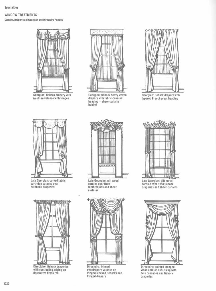
Specialties
WINDOW TREATMENTS'Curial ns/Draperles of Georgian and Directoire Periods

Specialties
WINDOW TREATMENTS
Curtains/Draperies of Victorian Period
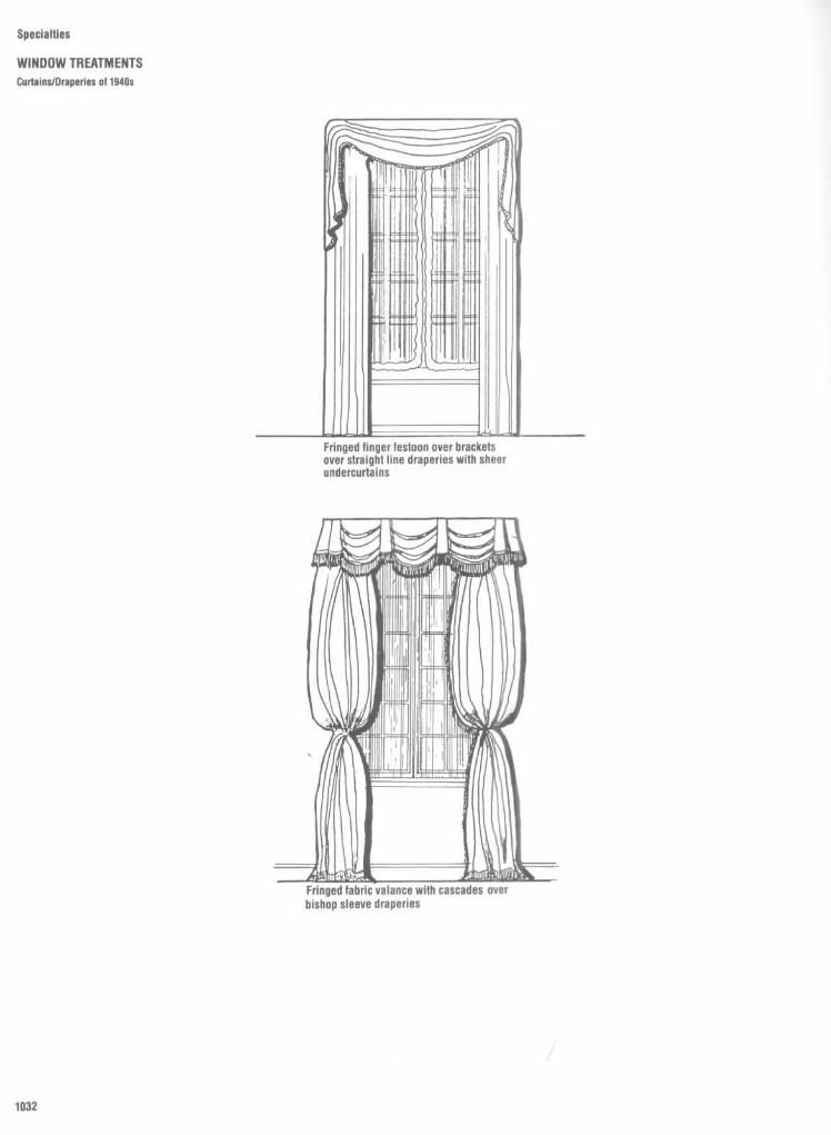
Specialties
WINDOW TREATMENTSCurtains/Draperies ol 1940s

Specialties
WINDOW TREATMENTSCurtains/Draperies

Specialties
WINDOW TREATMENTSCurlaIns/Draperies
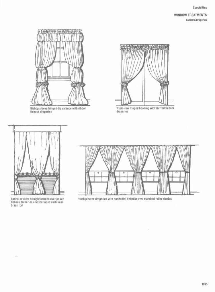
Specialties
WINDOW TREATMENTSCurtains/Draperies

Specialties
WINDOW TREATMENTSCurtains/Draperies

Specialties
WINDOW TREATMENTS
Curia Ins/Draperies

Specialties
WINDOW TREATMENTSCurtains/Draperies
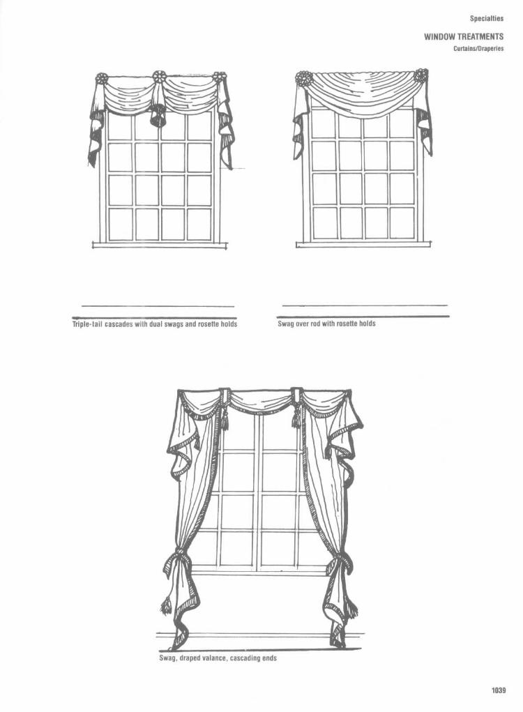
Specialties
WINDOW TREATMENTSCurtains/Draperies

Specialties
WINDOW TREATMENTSCurtains/Draperies

Specialties
WINDOW TREATMENTSCurtains/Draperies

Specialties
WINDOW TREATMENTSCurtains/Draperies

Specialties
WINDOW TREATMENTSHeadings

Specialties
WINDOW TREATMENTSHeadings

Specialties
WINDOW TREATMENTSTiebacks and Holdbacks

Specialties
WINDOW TREATMENTSTiebacks and Holdbacks

Specialties
WINDOW TREATMENTSMounts, Brackets, and Couplers

Specialties
WINDOW TREATMENTSFinials, Rings, and Hooks
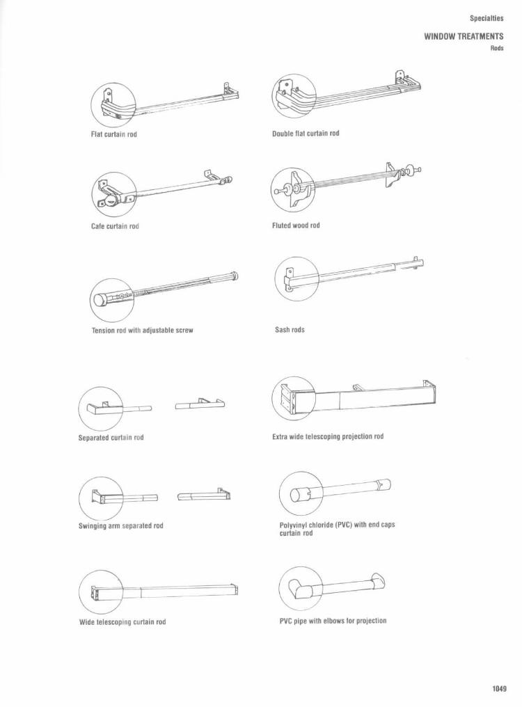
Specialties
WINDOW TREATMENTSRods

Specialties
WINDOW TREATMENTSTraverse Rods

Specialties
WINDOW TREATMENTS
Guidelines for Fabric Panel Widths and Rod Lengths
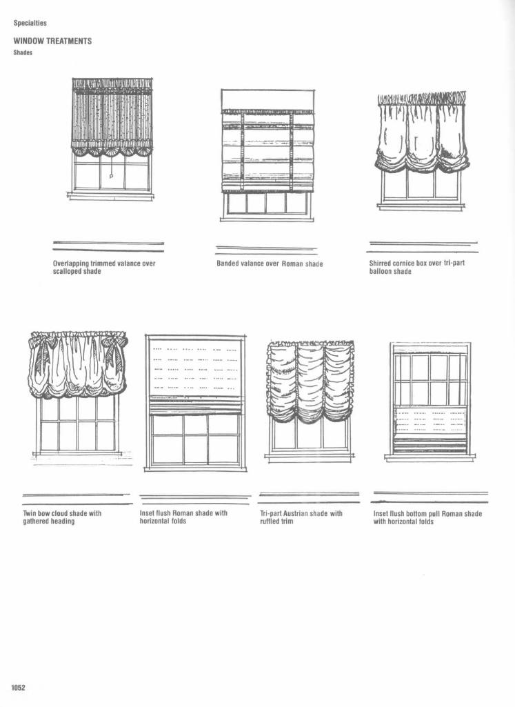
Specialties
WINDOW TREATMENTSShades

Specialties
WINDOW TREATMENTSShades

Fig . 8
Woven wood blinds . These blinds have horizontal or vertical reeds - long slats of woodfrom Ya to 1 inch width - that are held together by decorative vertical yarns . They range in designsfrom those that are made mostly from exposed wood to those that are mainly yarns of several colorscreating various interesting effects . Woven wood blinds can be used with many windowtreatmentsincluding draperies and café curtains, and such shade types as Roman-fold, spring-rolls, cord andpulley, and duo-fold . Top treatments include canopies, valances, and arches, while scallops,fringes, and trims are suitable for the bottom . Because woven wood blinds add color and texture to awindow, they are particularly adaptable to the "natural" look in decorating .
Specialties
WINDOW TREATMENTS
Shades
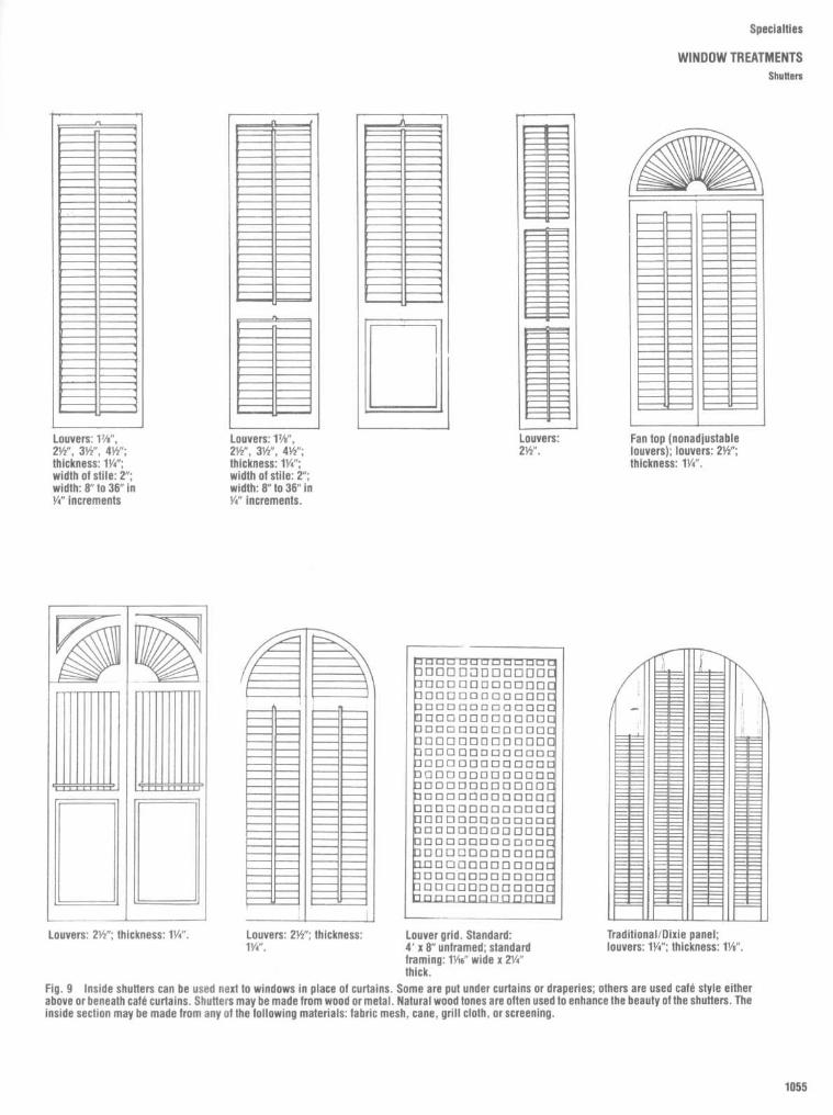
Specialties
WINDOW TREATMENTSShutters
Fig . 9
Inside shutters can be used next to windows in place of curtains . Some are put under curtains or draperies ; others are used café style eitherabove or beneath café curtains . Shutters may be made from wood or metal . Natural wood tones are often used to enhance the beauty of the shutters . ThEinside section may be made from any of the following materials : fabric mesh, cane, grill cloth, or screening .

Specialties
WINDOW TREATMENTSShutters

Specialties
WINDOW TREATMENTS
Shutters and Venetian Blinds
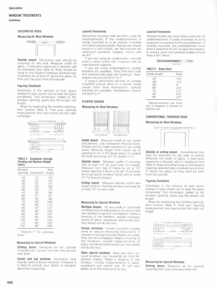
Specialties
WINDOW TREATMENTSGuidelines
DECORATIVE RODS
Measuring for Most Windows
II
.
Outside mount Decorative rods should bemounted on the wall Measure width ofglass; if total glass exposure is desired, addfor stackback (see Table 4) . Rods should behung so that drapery headings (pleated topsof panels) are at least 4" above the glass, sothey can't be seen from the outside.
Figuring Stackback
Stackback is the amount of wall spaceneeded if open panels are to clear the glasscompletely. This dimension, added to thewindow opening, gives you the proper rodlength .
Begin by measuring the window opening,then consult Table 4. Find your openingmeasurement and read across for the rightrod length .
Layered Treatments
Decorative traverse rods are often used forovertreatments . If the undertreatment isinside mounted or is an outside mountedmini-blind, pleated shade, Romanette wovenwood or a cafe curtain, set the brackets formaximum clearance. Drapery returns willbe 41/2" .
If you are using an undercurtain, you willwant a utility curtain rod. It comes with itsown bracket-supports .
If you are using underdraperies, doublebrackets are available . They hold both rodsand automatically align the headings . Over-drapery returns will be 6" to 7" .
If using a decorative rod over an outsidemounted vertical blind or a woven woodshade other than Romanette, specialbrackets are available . Overdrapery returnswill be 6" to 7" .
PLEATED SHADES
Measuring for Most Windows
Layered Treatments
Pleated shades are most often used with anundertreatment . If inside mounted, no extraprojection is needed for the overtreatment. Ifoutside mounted, the overtreatment musthave a clearance of 2112" to clear the headradA cornice used over pleated shades shouldhave a 41/2" return .
Measuring for Special Windows
Sliding doors Measure as for outsidemounted rod . Convert rod from two to one-waydraw.
Corner and bay windows Decorative rodsmay be used at these windows. However, itis best to consult your dealer or designerabout the measuring.
Inside mount
Measure width at top, centerand bottom . Use narrowest measurement.Shades will be made narrower to slip insideeasily. Measure length from inside top ofopening to sill . A 1 5/8" deep recess is neededfor flush mounting . 21/4' for Duette in s/4 .
Outside mount Measure width of opening.Add at least 11/2" on each side for overlap.Measure from top of frame to sill or 1112"below opening if there is no sill . (If bracketsare to go above window frame, add an extra1112" for bracket bases.)
Ceiling mount Measure desired width andlength of blind. Overlap window openings byat least 1112" on each side .
Measuring for Special Windows
Multiple shades
At very wide or sectionedwindows and at sliding doors, it's wise to usetwo shades hung from one headrad . Make adrawing of the window ; include measure-ments of glass, woodwork and overall size .Your dealer will do the rest .
Corner windows Inside-mounted shadesneed no special measuring instructions . Ifoutside or ceiling-mounted shades are used,they can be overlapped . Make a drawing ofthe windows ; include measurements ofglass, woodwork and overall size . Your dealerwill do the rest .
Other special windows Bays and other un-usual windows can frequently be fitted forpleated shades . Make a drawing of thewindow, include measurements of glass,woodwork and overall size . Or ask yourdealer to do the measuring for you
Outside or ceiling mount
Conventional rodsmay be mounted on the wall or ceiling .Measure the width of glass; if total glassexposure is desired, add for stackback (seeTable 4). Rods should be hung so that draperyheadings (pleated tops of panels) are at least4" above the glass, so they can't be seer.from the outside.
Figuring Stackback
Stackback is the amount of wall spaceneeded if open panels are to clear the glasscompletely. This dimension, added to thewindow opening, gives you the proper rodlength .
Begin by measuring the window opening,then consult Table 4. Find your openingmeasurement and read across the right rodlength .
Measuring for Special WindowsSliding doors Measure as for outsidemounted rod. Use a one-way draw rod .

Corner and bay windows
Measure each win-dow as if it were set flat into the wall . Atcorners, run one rod into the corner and buttthe other into it . At bays, butt all rods . Useeither one or two-way draw rods for corners.For bays, use three two-way rods or two one-ways with a two-way in the center.
Ceiling mount Measure desired width andlength of verticals ; deduct atleast 3/4"for floorclearance .
Cirmosa 2000
Ask your designer, decorator,or store to measure for you .
Measuring for Special Windows
Layered TreatmentsConventional traverse rods come in setsspecifically for layered treatments . If you areusing an undercurtain, you will want a tra-verse and plain rod set ; both rods are on oneset of brackets . Overdrapery returns will be4'/2" to 5'/2" .
If you are using underdraperies, use adouble traverse rod set . Again, one set ofbrackets holds both rods . Overdrapery re-turns will be 5th" to 6%2".
If the undertreatment is inside mounted oris an outside mounted mini-blind, pleatedshade, Romanette woven wood or a cafecurtain, use a single rod and set the bracketsfor maximum clearance . Drapery returns willbe 4%2".
If the undertreatment is an outside-mounted vertical blind or a woven woodshade other than Romanette, special ex-tender plates for brackets and supports areavailable . Overdrapery returns will be 5%2" to61/2" .Remember, whenever you change the
clearance of the brackets, you also changethe drapery return .
Inside mount
Measure width at top, centerand bottom . Use narrowest measurement .Verticals will be made slightly narrower to slipinside easily. Measure length from inside topof opening to sill . A minimum 3 1/4" recess isrequired for track ; 41/2" if open vanes are to beflush with front of opening .
Outside mount Measure width of opening .Add for stackback (see Tables 6 and 7) .Measure from a point 2 112" above top of frameto sill or floor ; deduct a/4" for clearance .Minimum projection of front of vane from
wall is 5" ; maximum is 6 1/2" . Minimum clear-ance of back of vane from wall is 1", max-imum is 2112" .
Sliding doors
Use a one-way draw. Measurewidth from trim to trim . Add to this measure-ment desired extra width for overlap beyonddoor. If total glass exposure is desired, alsoadd for stackback isee Tables 6 and 7) .Measure from a point 21/2" above door trim tofloor ; deduct 3/4" for clearance .
Layered TreatmentsWhen layered, verticals are most often usedas an undertreatment . If inside mounted, noextra clearance is needed for the overtreat-ment . If outside mounted, the overtreatmentmust have a clearance of 6" to clear the openvanes . A cornice used over verticals shouldhave a 6" return .
Figuring StackbackStackback is the amount of wall spaceneeded if open verticals are to cleartheglasscompletely. This dimension, added to thewindow opening, gives you the proper tracklength .
Begin by measuring the window opening,then consult Table 6 or 7 for the type oftreatment you desire - one- or two-waydraw. Find your opening measurement andread across for the right track . (Note :Stackback figure for two-way draw is totalstack ; one-half of this is on each side of thewindow.)
If your window opening is somewhere inbetween the measurements in the tables,go to the next smallest opening . Add thestackback listed there to your openingdimension .
Specialties
WINDOW TREATMENTSGuidelines
MINI BLINDS
Measuring for Most WindowsInside mount
Measure width at top, centerand bottom . Use narrowest measurement .Blinds will be made slightly narrower to slipinside easily. Measure length from inside topof open to sill . A 1Ye" deep recess is neededfor flush mounting of Mono-Rail minis ; how-ever, a difference of 114" is not objectionable .Outside mount
Measure height and width ofarea to be covered . It is recommended thatblinds overlap window opening by at least1 1/2" on each side . Measure from top of frameto sill or 11k" below opening if there is no sill .
Ceiling mount Measure desired width andlength of blind . Overlap window openings byat least 116" on each side .

Specialties
ELEVATORSElevator Types and Planning
ELEVATOR TYPESHydraulic : For low-rise buildings -
speeds up to 200 ft/min . Ideal where designlimitations preclude overhead supports andmachine rooms . Economical to install andmaintain ; no penthouse or load-bearing wallsrequired .
Geared traction : For low- to medium-rise buildings - speeds up to 400 ft/min .Recommended for all types of buildingswhere higher speeds are not essential .
Gearless traction : Recommended forhigh-rise applications requiring the ultimatein service -speeds of 500 fVmin and up.
ELEVATOR PLANNINGStarting Point Recommendations forAll Types of BuildingsWhen preparing schematics for a particulartype of building, select the quantity, capacity,and speed from one of Tables 1 to 4 and keepin mind that generally speaking :
ss Passenger elevators should be wide andshallow with center-opening or single slidedoors .n Service elevators should be narrow and
deep with two-speed doors .as Combination passenger/service ele-
vators should be almost square with eithercenter-opening or two-speed center-openingdoors .
Freight elevator size and shape shouldbe determined bythe dimensions of goods tobe carried and by the loading/unloadingmethods used . Doors should be of the ver-tical bi-parting type .The data contained in Tables 1 to 4 are
based upon the following criteria .
Office buildings
100 square feet per person ;an interval of 30 sec . ; net rentable area =80% of gross area ; 5 minute carrying capac-ity of 12% of building population ; typical floorheights were estimated at 12' and the mainfloor at 18'. When the building exceeds250,000 square feet total, it is suggested thatconsideration be given to the use of separatefreight elevators which are not included inTable 1 .
Hospitals
5minute vehicular demand = .04x the number of beds ; interval of 35-50seconds for vehicular traffic ; visitor and staffpopulation = 3 x number of beds ; 5 minutecarrying capacity equal to 12% of buildingpopulation .
Hotels Registration during conventions =1 .5 x the total number of rooms ; maximum 1hour peak is 1 .15 x total registrations ; 5minute carrying capacity = 10% of total 1hour peak load .
Apartments
Population est . (6t 2 persons perbedroom ; 5 minute carrying capacity of 7% ;maximum waiting interval of 60-90 seconds ;average of 9'0" floor height . Further, Table 4applies only for average or middle incomeapartments . For applications beyond thescope of the table such as local-expressarrangements, luxury apartment buildingsand other considerations, please consultyour local elevator company representative .Note : If a restaurant or general assembly
area is located in your building ion any but themain floor) and is not served by a separateelevator, the information contained in Tables 1to 4 may not apply.

Specialties
ELEVATORSLow-and Mld-Rise Elevators
POWER UNIT (MACHINE) LOCATION : The most desirablemachine room location is on the lowest floor, adjacent to theelevator hoistway It may, however, be located remote from hoist-way if necessary. Typical size for one-car installation 7' 10"x5'-6"x 8'-0" high, for two cars 10'-9" x 6'-6" x 8'-0" high Enclosureto meet local code requirements must be provided A sound-isolated machine room is recommended for quietest operationAdequate heating and ventilation of machine spaces must beprovided
HYDRAULIC ELEVATORSIdeal for use in buildings up to six floors .Supported and raised by a powerful hydraulicplunger, the Oildraulic is renowned forsmooth performance, quiet operation, andaccurate floor leveling . And since it's sup-ported from below, no vertical load is placedon the building . That means hoistways canbe of lighter construction and no penthouseis needed . The machine room can be locatednearly anywhere to let you maintain a flat roofline and save money on construction

Specialties
ELEVATORS
High-Rise Elevators
TRACTION ELEVATORS
For use in buildings over six floors . They canserve up to 27 landings and can be used inoffice buildings, apartment complexes, dor-mitories, hotels, and other structures . Theseelevators can travel up to 1000 ft/min and areideal for high-rise buildings of all kinds .
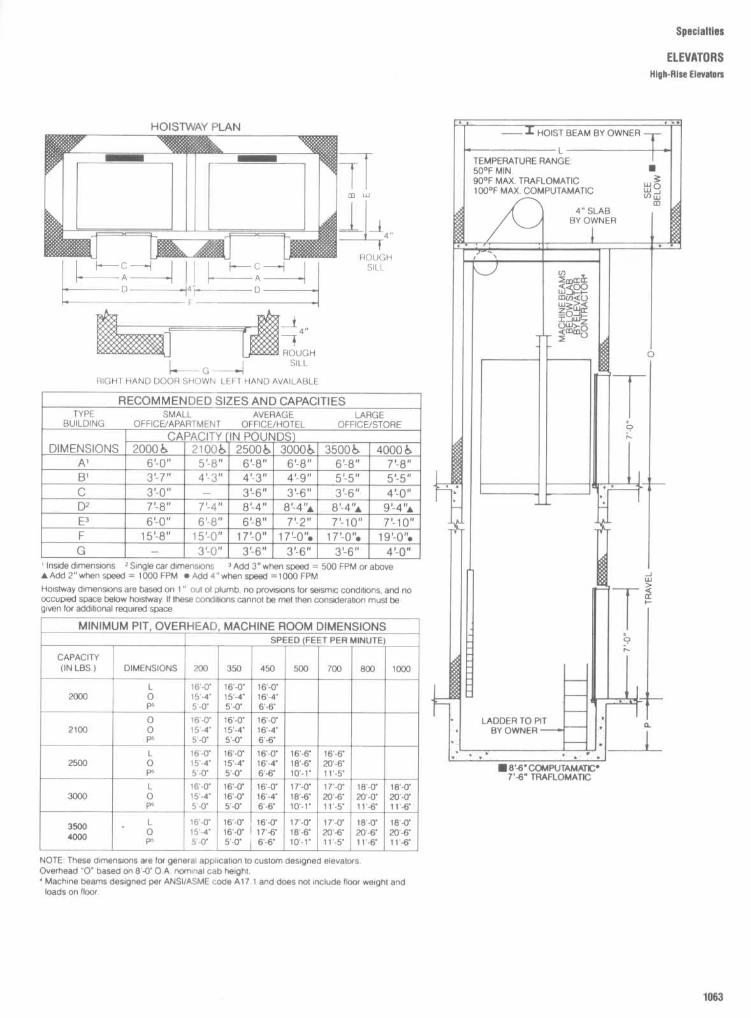
Specialties
ELEVATORS
High-RIse Elevators

Specialties
ELEVATORS
Passenger Elevator Door/Entrance Details

Specialties
ELEVATORS
Barrier-Free Considerations
Floor plan of elevator cars
The floor area ofelevator cars shall provide space for wheel-chair users to enter the car, maneuver withinreach of controls, and exit from the carAcceptable door opening and inside dimen-sions shall be as shown in Fig. 1 . Theclearance between the car platform sill andthe edge of any hoistway landing shall be nogreater than 1'/4 in (32 mm).
Illumination levels The level of illuminationat the car controls, platform, and car thresh-old and landing sill shall be at least 5 footcan-dles (53.8 lux).
Car controls Elevator control panels shallhave the following features :
1 . Buttons. All control buttons shall be atleast 3/4 in (19 mm) in their smallest dimen-sion . They may be raised or flush.2. Tactile and visual control indicators . All
control buttons shall be designated by raisedstandard alphabet characters for letters, ara-bic characters for numerals, or standardsymbols as shown in Fig. 3(a), and as re-quired in ANSI A17 .1-1978 and A17.1a-1979 .The call button for the main entry floor shallbe designated by a raised star at the left ofthe floor designation [see Fig. 3(a)] . All raised
designations for control buttons shall beplaced immediately to the left of the buttonto which they apply. Applied plates, perma-nently attached, are an acceptable means toprovide raised control designations . Floorbuttons shall be provided with visual indica-tors to show when each call is registered .The visual indicators shall be extinguishedwhen each call is answered .
3 . Height . All floor buttons shall be nohigher than 48 in (7220 mm), unless there is asubstantial increase in cost in which casethe maximum mounting height may be in-creased to 54 in (7370 mm), above the floor.Emergency controls, including the emer-gency alarm and emergency stop, shall begrouped at the bottom of the panel and shallhave their centerlines no less than 35 in (890mm) above the floor [see Fig. 3(a) and (b)j .
4. Location . Controls shall be located on afront wall if cars have center opening doors,and at the side wall or at the front wall next tothe door if cars have side opening doors [seeFig . 3(c) and (d)j .
Car position indicators In elevator cars, avisual car position indicator shall be providedabove the car control panel or over the door
to show the position of the elevator in thehoistway. As the carpasses or stops ata floorserved by the elevators, the correspondingnumerals shall illuminate, and an audiblesignal shall sound. Numerals shall be a mini-mumof 112 in (13 mm) high . The audible signalshall be no less than 20 decibles with afrequency no higher than 1500 Hz . An auto-matic verbal announcement of the floornumber at which a car stops or which a carpasses may be substituted for the audiblesignal .
Emergency communications If provided,emergency two-way communication sys-tems between the elevator and a pointoutside the hoistway shall comply with ANSIA17 .1-1978 and A17.1a-1979 . The highestoperable part of a two-way communicationsystem shall be a maximum of 48 in (1220mm) from the floor of the car. It shall beidentified by a raised or recessed symbol andlocated adjacent to the device . If the systemuses a handset, then the length of the cordfrom the panel to the handset shall be at least29 in (735 mm). The emergency intercom-munication system shall not require voicecommunication .
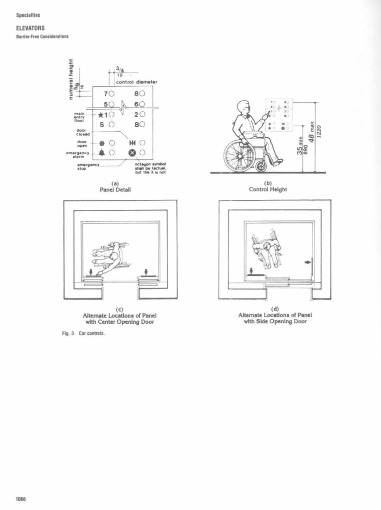
Specialties
ELEVATORSBarrier-Free Considerations

Specialties
ELEVATORS
Typical Section of Escalator

Specialties
ELEVATORSWheelchair Lifts
Fig . 4
Wheelchair lift. In certain installations where ramps may be impossible due to space limitations, small mechanical wheelchair lifts can be installed toovercome level changes . Manufactured lifts have a lift range from two to several feet and are either electro-mechanical, hydraulic, or pneumatically operated . Liftscan be semi-enclosed and equipped with entrance interlocks for safety, and either key-operated for limited use or button-type . "Dead-man" controls are recommendedfor safety.

Specialties
INDOOR RECREATION
Basketball
Fig . 1
NCAA basketball . The color of the lane space marks and neutral zone marks shall contrast with thecolor of the bounding lines . The midcourl marks shall be the same color as the bounding lines . All lines shallbe 2 in wide (neutral zone excluded). All dimensions are to inside edge of lines except as noted . Backboardshall be of any rigid weather-resistant material . The front surface shall be flat and painted white unless it istransparent . If the backboard is transparent, it shall be marked with a 3-in wide white line around the borderand an 18 x 24-in target area bounded with a 2-in wide white line . [High school recommended court is 84 x 50 ftwith a 10-ft unobstructed space on all sides (3 ft minimum). Collegiate recommended court is 94 x 50 It with a10-it unobstructed space on all sides (3 ft minimum) .]
Fig . 2
AAU basketball court . All dimensions are to inside edge of lines exceptas noted . All lines tobe .05 m (2") wide . Backboard shall be of any rigid weather-resistant material . The front shall be flatand painted white unless it is transparent. If the backboard is transparent, it shall be marked with a.05-m-wide white line around the border and a .45 x .59-m target area bounded with a .05-m-widewhite line .

Specialties
INDOOR RECREATIONOne-, Three-, and Four-Wall Handball
Fig . 3
One-wall handball . Playing court is 20'0" wide by 34'0" long plus a required 11'0" minimum width of surfaced area
to the rear and a recommended 8'6"minimum width on each side . Courts in battery are to be a minimum of 6'0" between
courts . Court markings: 11 1h-in-wide lines painted white, red, or yellow .
Fig . 5
Handball court layout-three-wall . All court markings to be11/2 in wide and painted white, red, or yellow. Playing court is 20'0"wide by 40'0" long plusa minimum 10'0"to the rear of the three-wallcourt . Overhead clearance required is 20'0" minimum .
Fig . 4
Handball court layout - four-wall . All court markings to be1 1/2 in wide and painted while, red, or yellow.

Specialties
INDOOR RECREATION
Gymnasium

Specialties
INDOOR RECREATION
Tennis and Paddle Tennis
Fig . 7
Tennis court. All measurements for court markings are to the outside of linesexcept for those involving the center service line which is equally divided between theright and left service courts . All court markings to be 2 in wide .
Fig . 8
Paddle tennis court . All measurements for court markings are to the outside oflines except forthose involvingthe center service line, which is equally divided betweenright and left service court. All court markings to be 11/2 in wide .

Fig . 10
Volleyball court . All measurements for court markings are to the outside of
lines except for the centerline . All court markings to be 2 in wide except as noted .
Fig . 9
Badminton court . All measurements for court markings are to the outside oflines except for those involving the center service line which is equally divided between
right and left service courts . All court markings to be 11/2" wide and preferably white or in
color. Minimum distance between sides of parallel courts to be 5'0" .
Specialties
INDOOR RECREATION
Badminton and Volleyball

Specialties
INDOOR RECREATIONShuffieboard
Fig . 11
Shuffleboard court. All dimensions are to centers of lines and to edge of court . Maximum line width 1Ys in, minimum 3/. in . Playing court is6'0" x 52'0" plus a recommended minimum of 2'0" on each side or 4'0" between courts in battery.

Speciatties
ACCESSORIES
Letter Boxes

Specialties
ACCESSORIESMail collection Boxes

Specialties
ACCESSORIES
Mail Drops

Specialties
ACCESSORIES
Mall Chutes, Parcel Lockers, and Key Cabinets

Specialties
ACCESSORIES
Telephone Boolhs
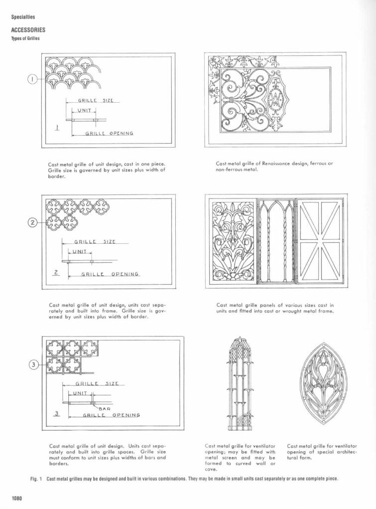
Specialties
ACCESSORIES
Types of Grilles

Fig . 2
Stamped metal grilles are produced in a great variety of designs, metals, thicknesses, and sizes . Percentage of free area of stamped grilles may vary fromabout 25% to over 70%, with a great many designs in the 55% to 65% range . Margin widths can be made to accord with requirements of particular installations,consideration being given to duct openings and overall dimensions . Metal may be steel, painted or otherwise finished, bronze, aluminum, monel metal, or othernonferrous metals, in thicknesses from 16 gauge to Yi' .
Specialties
ACCESSORIES
Types of Grilles
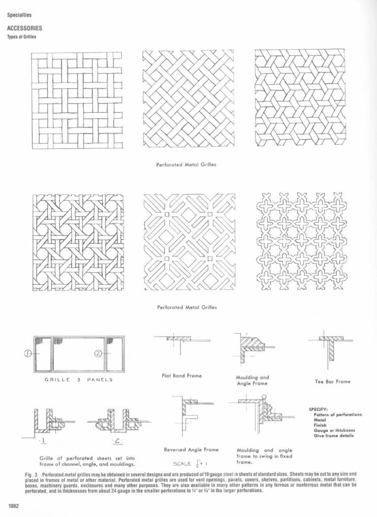
Specialties
ACCESSORIES
Types of Grilles
Fig . 3
Perforated metal grilles maybe obtained in several designs and are produced o119 gauge steel in sheets of standard sizes . Sheets maybe cut to any size and
placed in frames of metal or other material . Perforated metal grilles are used for vent openings, panels, covers, shelves, partitions, cabinets, metal furniture,
boxes, machinery guards, enclosures and many other purposes . They are also available in many other patterns in any ferrous or nonferrous metal that can be
perforated, and in thicknesses from about 24 gauge in the smaller perforations to 1/a" or 3/e" in the larger perforations .

Fig . 4
Design of wrought metal grilles includes the use of other metal forms, such as sheets, extruded mouldings, castings, and stampings . Thus, in addition toplain bar sections and forged items, use is made of the unlimited number of extruded mouldings in non-ferrous metals ; stamped leaves, rosettes, and ornaments ofmany kinds; cast iron, bronze, nickel silver, and aluminum items of every character; and rolled or drawn sections of many shapes .
Specialties
ACCESSORIES
Types of Grilles

Specialties
ACCESSORIES
Types of Grilles
Fig . 5
Window grilles are of plain construction when used for protection only, and when used for ornamental effect, may be designed with many unique andinteresting ideas . Window grilles may be set in the masonry openings or on the face of the wall, with either plain or ornamental brackets or supports . They may alsobe attached to window frames, or may be arranged to swing, with hinges and locks . Material sizes in window grilles may vary according to the degree of protectionrequired, and in proportion to the size of the grille .

Specialties
ACCESSORIES
Grille Fastening Methods
Fig . 6
Methods of fastening grilles . Cast and stamped metal grilles may be fastened by screws or hinges and locks to walls of wood, plaster, marble, or othermaterial in a variety of ways, depending upon the type of the grille, the type of framing to be used around the grille, and the appearance or effect desired . Thesemethods show a number of ways in which cast and stamped grillesmaybe fastened . In selecting the method desired, consideration should be given to whether or notthe grille will require frequent removal . The size and weight of the grille will have a bearing upon the size of frames, screws, and hinges .

Specialties
ACCESSORIESGrille Fastening Methods

Specialties
ACCESSORIES
Protection Guards

Specialties
ACCESSORIESVinyl Wall Protection Guards

Specialties
ACCESSORIES
Handrails

specialties
ACCESSORIES
Chalkboard Details

Specialties
ACCESSORIES
Column Covers

Specialties
ACCESSORIESColumn Covers

Specialties
ACCESSORIESColumn Covers

Specialties
ACCESSORIESColumn Covers

Specialties
ACCESSORIES
Column Covers

Specialties
ACCESSORIESColumn Covers

Specialties
ACCESSORIESTUrnsfites

Specialties
ACCESSORIES
Turnstiles
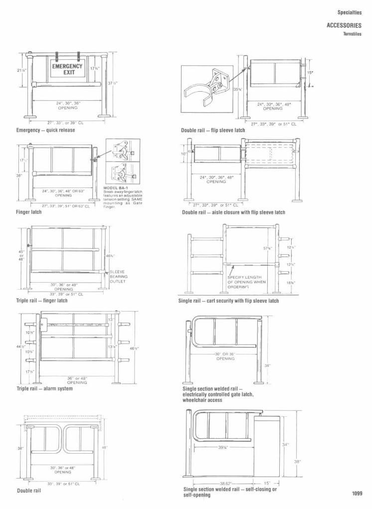
Specialties
ACCESSORIES
lbrnsfites

Specialties
ACCESSORIESWater Coolers

Specialties
ACCESSORIES
Water Coolers

Specialties
ACCESSORIESAccessible Drinking Fountains

General Reference DataSpace planning
1106Human factors
1110Floor and wall covering
1122Fabric
1130Electrical
1132Columns, capitals, and entablatures
1135Nails, screws, and bolts
1136Mathematical data and formulas
1139


General Reference Data
INTRODUCTION
This section provides a variety of time-saving reference material in the formof tables, charts, formulas, and planning guidelines . Included are arearequirements for the preliminary space planning of various building types andhuman factors data related to anthropometrics, space, and acoustics . Alsoincluded are a number of tables for determining carpet and wall coveringyardage quantities . In addition, a series of tables dealing with electrical dataprovides typical amperage ratings for office and electronic equipmentand forresidential appliances . Still other tables and chart. contain mathematical datarelative to functions of numbers, metric system conversions, and areas ofplane figures.

General Reference Data
SPACE PLANNINGArea Requirements ByUse
The first portion of Table 1 shows some ofthe planning guidelines for several types ofoffice use. Of course, usable areas per em-ployee vary greatly depending on the type ofwork performed and types of support spaceand common areas required, such as filerooms, data processing, conference rooms,and so forth .
Rules ofThumbOffice use: 125 to 150 net sq . ft . area
per person .Retail space: 30 net sq . ft. per person
on ground floor ; 50 net sq . ft . per person onupper floors .
Classrooms : 20 net sq . ft . per pupil .
TABLE 1 Space Planning By Building Type
Building/Use Type Sq. Ft . per Unit Area Basis
Office buildings, all types 100-250 net usableWork station, minimum clerical 40 person usableWork station, clerical with VDT 55 person usableWork station, with visitor space 65 person usableWork station, supervisor 100 person usableManager, private office 150-225 person usableLaw firm 450 attorney total usableLaw firm library 25-30 attorney usableLaw firm conference 25-30 attorney usableInsurance company, branch 100 average work station usableInsurance company, branch 155-165 employee total usable
Total, includes commonareas and circulation
Energy company 255 employee total usableConference and dining rooms 15 person net
RestaurantsDining areas (includes dining room but not waiting, coat room, etc.)Banquet 10-15 seat netCafeteria, college 12-15 seat netCafeteria, commercial 16-18 seat netCounter service 18-20 seat netTable service, hotel or
restaurant 15-18 seat netTable service, minimum 11-14 seat net
KitchensMeals per Hour
Type < 200 200-400 400-800 800-1300
Cafeterias 7.5-5 .0 5.0-4.0 4.0-3 .5 3.5-3 .0Hotels 18.0-4.0 7.5-3 .0 6.0-3.0 4.0-3 .0Restaurants 7.0-4 .0 5.0-3.6 5.0-3 .6 5.0-3 .0Serving and service areas
Cafeterias 6 person netRestaurants 5 person net
Add to totals space for food storage, administration, waiting .

General Reference Data
SPACE PLANNINGArea Requirements By Use
TABLE I Space Planning By Building Type (Continued)
Building/Use Type Sq . Ft . per Unit Area Basis
Night clubs 25 person netBars 18 person net
Hotel1 .5 persons per room without 550-600 room grossextensive conferencingfacilities
RetailLarge stores 30-50 person net
Cultural
Public libraryStack space 0.08 bound vols . netReading rooms 20-35 user netStaff space 100 staff person netOverall 50 person net
Museums, exhibition areas 15 person netTheater and assembly areas
Seating area, fixed seats 7.5 seat netSeating, movable seating 15 seat netTheaters, fixed seating 8-12 seat net(Does not include stage, lobby,etc.)
Stage/backstage 100% seating areaPerforming arts theater
Lobbies 3 person netLobbies 30% seating area
Educational
ElementaryThe following figures are based on the number of students in the particular spacelisted .Small classrooms 20-30 student netLibrary 40 student netArt room 40 student net
SecondaryThe following figures are based on the number of students in the particular spacelisted .Cafeteria 12-15 student 1/3 of totalSmall classrooms 20-25 student netLarge classrooms 15 student netArt classrooms 50-60 student netHome economics 50-60 student netLaboratory classrooms 55-70 student netLibrary 40 student 20% of totalMusic rooms 30-35 student netPhysical education 125 student netShops/vocational rooms
small 50 student netShops/vocational rooms
wood, metal, etc. 120-140 student netUniversityClassrooms, small 20 student netClassrooms, large 12-15 student net

General Reference Data
SPACE PLANNINGArea Requirements By Use
TABLE 1 Space Planning By Building Type (Continued)
BuildinglUse Type Sq . Ft . per Unit Area Basis
Lecture halls 9-12 seat netDormitory, no dining 160 student netDormitory, no dining 210-240 student grossDormitory, dining 235-260 student grossFood service, table service 18-26 seat net, all areasFood service, cafeteria 14-19 seat net, all areasLaboratories 34-45 student netLaboratory storage 6-10 student netLibrary
Book stacks, less than300,000 volumes 0.10 volume net
Book stacks, 300,000-1,000,000 volumes 0.7-0.8 volume net
Book stacks, over1,000,000 volumes 0.5 volume net
Reading, study 25-35 station net(provide stations equal to 25% to 40% of student population) :
6.25-10 student netTotal service space 25% of reading net
Residential
Apartments 250 Occupant netSenior citizen housing
Living units 300-380 1-person unit netLiving units 350-425 2-person unit netLiving units 400-600 unit grossDining, lounge, lobby,
administration, etc. 33%-45% of living unit space, gross area
Health Care Facilities
General hospital 1000 bed grossMedical center 1100 bed gross
The above figures are based on usable square footage, which In the language of leasing includes the areawithin the boundaries of the leased space. Most building owners lease space based on the rentable area,which includes a tenant's prorated share of common areas such as toilet rooms, elevator lobby, publiccorridors, and so on. The multiplying figure can be obtained from the building owner, or a figure of 1 .1 to1 .15 can be used as an estimated multiplying factor.
TABLE 2 Gross to Net Ratios for Common Building Types
Building Type Multiplying Factor Building Type Multiplying Factor
Office 1 .25-1 .35 Library reading space 1 .5Retail 1 .35 Museum 1 .2Bank 1 .4 Theater 1 .3-1 .7Restaurant, table service 1 .4-1 .5 School, classroom 1 .5-1 .65Restaurant, cafeteria 1 .5 School, dormitory 1 .5-1 .8Bars, nightclubs 1 .3-1 .4 School, laboratory 1 .7Hotel 1 .4-1 .6 School, gymnasium 1 .4-1 .45Public library 1 .25-1 .3 Apartment 1 .25-1 .5Library stack space 1 .1-1 .3 Hospital 1 .5-1 .85

General Reference Data
SPACE PLANNING
Library Area Requirements
LIBRARY PLANNING
Libraries represent a unique building type inthat a majority of space is devoted to housingbooks and not people . The number of vol-umes to be housed becomes the primaryplanning parameter, rather than numbers ofpeople . For a detailed layout of book stacks,you can use the figures given in Table 3 . Forpreliminary planning, the following generalguidelines are useful .
Rules of Thumb
Public library: 12 -18'/2 volumes persq . ft .
Law library : 5-7 volumes per sq, ft .To stack space, add a "configuration
loss" of from 6% to 20%, to account forinefficiencies in stack layout .
Minimum aisle between open stacks .3 ft . 0 in .
Staff spaces : 100 net sq . ft . per person .Reading room seating . 15-35 sq . ft . per
person plus 6% configuration loss .Net/gross multiplier : 1 .25.Maximum of 15,000-20,000 sq ft . per
floor.
Example
A100,000 volume public library isplanned . How much space should be de-voted to open stacks?
Plan about 15 volumes per sq . ft . (100,00015 - 6667 sq . ft .) . Add a configuration loss
of 10%, to give a total area of 6667 + 667. or7333 sq . ft . of stack space.
TABLE 3 Library Shelving -Volumes per Linear Foot of Shelf Based on Subject(Standard stack section 3 ft wide x 7'/2 ft high with 7 shelves)
Volumes per foot Volumes per singleSubject of shelf face section
Art (excluding oversize) 7 147Circulating, nonfiction 8 168Economics 8 168Fiction 8 168General literature 7 147History 7 147Law 4 84Medical 5 105Periodicals, bound 5 105Public documents 5 105Technical and scientific 6 126
Average for overall estimating 125
These figures should be reduced by at least 10% to avoid overcrowding and toallow for expansion

General Reference Datl
HUMAN FACTORS
Anthropometrics
APPROPRIATENESS
It is essential, due to the many variablesinvolved, that the data selected be appropri-ate to the user of the space or furniture to bedesigned . It becomes necessary, therefore,for the intended user population to be prop-erly defined in terms of such factors as age,sex, occupation, and ethnicity. If the user isan individual, or constitutes a very smallgroup, it may, in certain situations, be feasibleto develop your own primary anthropometricdata by actually having individual body mea-surements taken . Surely, if one is prepared totake the time to be fitted for a dress or a suit,one should be willing to spend the time to befitted for an interior environment or compo-nents of that environment, particularly since,in most cases, the latter will reflect a fargreater financial investment . The measure-ments, in the event individual data are gener-ated, should, however, be taken with properinstruments by a trained observer. In situa-tions where specific body dimensions orother data for a particular user population areunavailable, and both time and funds preventundertaking sophisticated studies, anengineering anthropometrist can be con-sulted to discuss the statistical methods ofobtaining the necessary information .
in a reach situation can accommodate theuser with the shortest arm reach, obviously itwill function for the users with longerreaches as well ; it is equally obvious that theopposite is not true, as shown in Fig. 1(a) .
In designs where clearance is the pri-mary consideration, the larger or 95th per-centile data should be used . The logic issimple . If the design will allow adequateclearance for the users with the largest bodysize, it would also allow clearance for thoseusers with smaller body size . Here, too, it canbe seen from Fig . 11b) that the opposite is nottrue .
In other situations it may be desirable to
provide the design with a built-in adjustmentcapability. Certain chair types, adjustao-eshelves, etc., are examples of such . Therange of adjustment should be based on theanthropometrics of the user, the nature ofthetask, and the physical or mechanical limita-tions involved . The range should allow thedesign to accommodate at least 90 percentof the user population involved, or more .
It should be noted that all the foregoingexamples were used primarily to illustratethe basic logic underlying the selection of ttsebody dimensions involved and the particutarpercentiles to be accommodated . Whereve"possible, however, it is naturally more des+r-
"AVERAGE MAN" FALLACY
As suggested previously, a very serious errorin the application ofdata is to assumethat the50th percentile dimensions represent themeasurements of an "average man" and tocreate a design to accommodate 50th per-centile data . The fallacy in such an assump-tion is that by prior definition 50 percent ofthe group may suffer. There simply is no"average man ." Depending on the nature ofthe design problem, the design should usu-ally be conceived to accommodate the 5th orthe 95th percentile, so that the greatestportion of the population is served .
Dr H.TE . Hertzberg, one of the country'smost distinguished research physical an-thropologists, in discussing the so-calledaverage man, indicated, "there is really nosuch thing as an 'average' man or woman .There are men who are average in weight, orin stature, or in sitting height, but the menwho are average in two dimensions con-stitute only about 7 percent of the popula-tion ; those in three, only about 3 percent;those in four, less than 2 percent. There areno men average in as few as 10 dimensions .Therefore, the concept of the 'average' manis fundamentally incorrect, because no suchcreature exists . Work places to be efficientshould be designed according to the mea-sured range of body size ."
REACH, CLEARANCE, ANDADJUSTABILITY
The selection of appropriate anthropometricdata is based on the nature of the particulardesign problem under consideration. If thedesign requires the user to reach from aseated or standing position, the 5th percen-tile data should be utilized . Such data for armreach indicates that 5 percent of the popula-tion would have an arm reach of short forshorter) dimension, while 95 percent of thepopulation, the overwhelming majority,would have longer arm reaches. If the design

General Reference Data
HUMAN FACTORSAnthropometrics

able to accommodate the greatest percent-age of the user population . In this regard,there is no substitute for common sense. If ashelf can just as easily be placed an inch ortwo lower, without significantly impacting onother design or cost factors, thereby accom-modating 98 or 99 percent of the userpopulation, obviously that is the correct de-sign decision .The clearances shown in Fig. 3 are
intended to introduce general guidelines forbarrier-free design . While we have utilizedthe wheelchair as our design subject, it doesnot represent the largest number of disabled .However, it is usually the most demandingfor which to design To provide practical limitsfor this design, we have chosen to plot therange of reach for the short female to the tallmale . The overlapping areas of ability for thehandicapped and the non-handicapped dem-onstrate the field of good design practicecommon to both .When planning for accessibility, it is impor-
tant to consider the attitude at which thewheelchair approaches the object desired.Reach limits differ for frontal and side reach.Because of this, range of reach is plotted foreach . The elevation targets represent themaximum height at which controls requiringmanual dexterity should be located.Wheelchairs vary in size . They are fitted to
their users in much the same manner asclothing is . A range of sizes is given, with thedimensions for the "typical" collapsible,manual chair indicated. Electrically poweredwheelchairs require more space . Further,the wheelchair must be considered in its "oc-cupied" state, as the user imparts additionalspace requirements with arms and feet aswell as basic maneuvering space.We consider the basic space requirement
for an occupied wheelchair to function to be3 ft wide by 4 ft deep . This same space willaccommodate most people who use canes,crutches, and walkers . Blind people using thecane technique for perceiving obstacles canalso be accommodated in this space . For aperson in a wheelchair to make a completeturn, an area of approximately 5 ft by 5 ft isrequired . As the elevations of surroundingsurfaces change, so do the space require-ments . The length of time that one is con-fronted by close quarters also affects therequired clearance. An opening through awall maybe 2 ft 8 in clear as it represents onlya short time involvement . As travel distanceand traffic increase, passage width mustalso .The complexity of space also affects mini-
mum clearance. To make a simple 90° turn,adjoining passages 3 ft wide are required(and 3 ft 6 in preferred if a normal walking is tobe maintained). A 180° turn around a fixedpartition requires more space.As clearances relate to general circulation
requirements, space needs again increasewith traffic speed and volume . Narrow cor-ridors (4 ft) should be restricted to basicallyshort, one-directional traffic patterns . Gener-ally, maintain at least 5 ft clearances or moreas determined by code .
General Reference Data
HUMAN FACTORS
Anthropometrics

General Reference Data
HUMAN FACTORSAnthropometrics

General Reference Data
HUMAN FACTORSWheelchair Dimensions
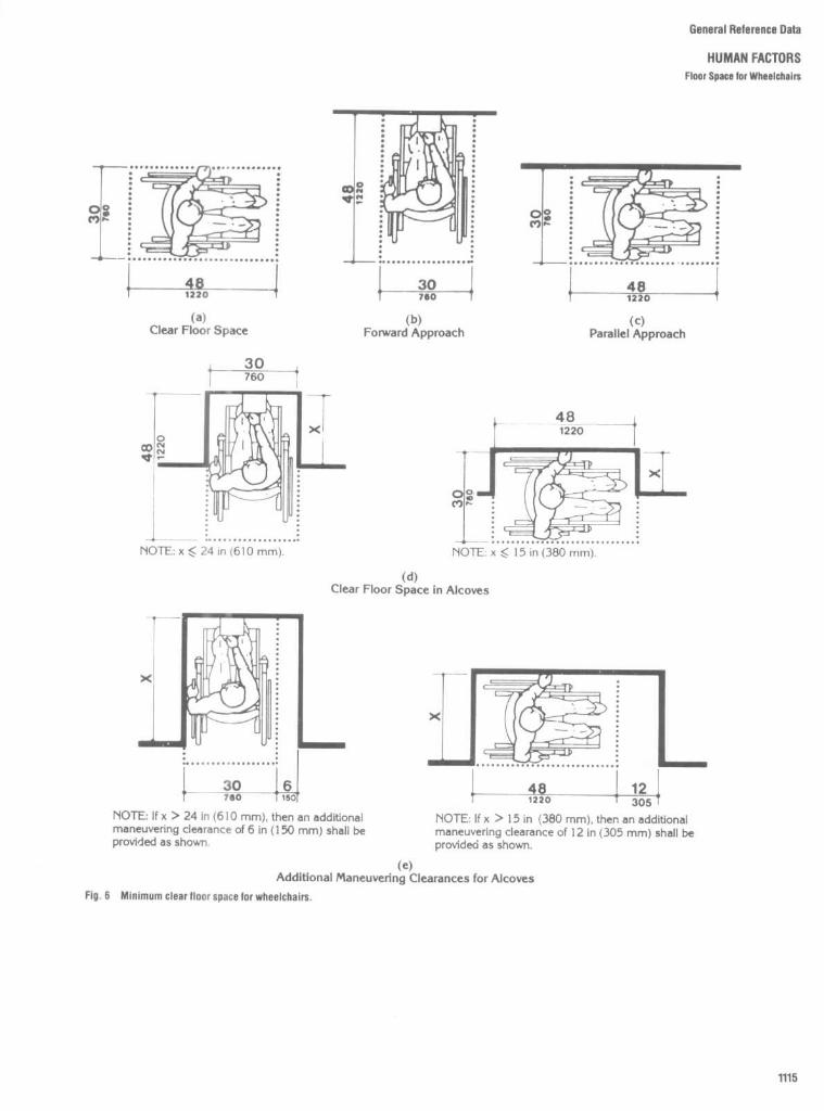
General Reference Data
HUMAN FACTORSFloor Space for Wheelchairs

General Reference Data
HUMAN FACTORSWheelchair Clearances at Doors
Pull Side
, . .�� . . .' .",
~
Push Side
pntD
18 min i, 24 nr hmrd
oa455
(VOTE: x - 12 in (305 mm) If door has both acloser and latch
(a)Front Approaches - Swinging Doors
Pull Side
Push Side
$4mln. . . . . . . . . . . . . . . . . . . . . . . . . . . . . . .
' .7774. . . . .
,~
É
a> âg
NOTE x = 36 in (915 mm) minimum if y = 60 in(1525 mm) ; x= 42 in (1065 mm) minimum if y =54 in (1370 mm) .
NOTE : y = 48 in (1220 mm) minimum if door hasboth a latch and closer.
(b)Hinge Side Approaches - Swinging Doors
XPutt Side
24 min
X
Push Sidesto
24min61o
C~
1
-1
1>co-
:YC14V4
(VOTE : y = 54 in (1370 mm) minimum If door hascloser.
NOTE y = 49 in (1720 mm) minimum if door hascloser.
(c)Latch Side Approaches - Swinging Doors
NOTE : All doors in alcoves shall comply with the clearances for front approaches
54 min137.0
l
(d)
(e)Front Approach - Sliding Doors
Slide Side Approach - Sliding Doorsand FoldingDoors
and Folding Doors
X
s, 24 min
Né0
(f)Latch Side Approach - Sliding Doorsand Folding Doors
NOTE : All doors in alcoves shall comply with the clearances for front approaches
Fig . 7
Maneuvering clearances at doors .

General Reference Data
HUMAN FACTORSWheelchair Clearances at Doors

General Reference Data
HUMAN FACTORSTelephone Mounting Heights; Control Reach

General Reference Data
HUMAN FACTORS
Space
TYPES OF SPACE
Besides needing enough space in order tomove about and perform various tasks, peo-ple react to space in a variety of ways .Several researchers have defined the spacesurrounding the individual in terms of thelimits within which people categorically re-spond (see Figs . 11 and 12). Intimate space isthat area in which a person tends not to allowanyone to intrude unless intimate rela-tionships are expected . Personal space isthat area within which a person allows onlyselected friends or fellow workers withwhom personal discussion is mandatory.Social space is that area within which theindividual expects to make purely socialcontacts on a temporary basis. And, finally,public space is that area within which theindividual does not expect to have directcontact with others . Obviously, the moreintimate the spatial relationship becomes,the more people resist intrusion by others .Personal space factors are important in es-tablishing the privacy requirements for archi-tectural design .

General Reference Data
HUMAN FACTORS
Space
TYPICAL SUBJECTIVE RESPONSESTO SELECTED SPATIAL FEATURES
Although few research data have been gee;erated with regard to how people respond tospecific spatial factors (at least in terms ofbeing able to prescribe precise, quantitativeguidelines), it is important for the designer toreflect on potentially negative reactions thatoften result when a given space is not madecompatible with what the user expects interms of the size, shape, organization, color,and illumination of a particular space. Theconsiderations listed in Table 4 are suggestedas a checklist for the designer.
TABLE 4
Space Characteristic Probable Response
Size (generally volume) If the space is too small for the number of people, furnishings,equipment, or other objects that occupy it, people will consider it tobe crowded. Although they may accept a crowded condition on atemporary basis. they will object to living or working in such a spacefor extended periods of time. If the space is too large for the people,furnishings, equipment, or other objects that occupy it, people wiltconsider it "unfriendly," inconvenient. and/or overly demanding interms of communicating, travel distance. maintenance. etc . Althoughthey may accept the "barnliké" atmosphere for temporary periods,they wIll object to living or working in such a space for extendedperiods of time.
Shape (generally proportion) If the space is out of proportion (too narrow, wide, long, high, etc .) lotthe intended use, people will consider it awkward and oftendistracting or oppressive . Although they may accept proportionaldistortion on a short-term basis (i.e ., as they pass through briefly),they will object to living or working in such a space for extendedperiods of time . If the space contains such distortions as alt curvedsurfaces . acute wall junctures, and too many projections or surfacechanges, people wilt consider it confusing and difficult to maneuver inand/or furnish . Although they may accept such distortions (or evenconsider them interesting) on a temporary or one-time basis, they willobject to living or working in such a space for extended periods oftime. It should also be noted that blind people depend on theconstant proportions of right-angle corners to aid them in negotiatinga space; such individuals are easily confused by curved surfaces,walls that are not at right angles, and periodic projections that implythey may have reached a turning point. When a ceiling is extremelyhigh relative to the lateral dimension of a space, people feel asthough they are working in a pit and that the walls are closing in onthem . When a ceding is extremely low and the space in front of theobserver is very long, people feel as though the room is "endless" oras if they will hit their heads unless they duck .
Color and illumination If a space is dark (unless thIs is required for a particular operation,such as a motion picture presentation), people tend to becomelethargic and less active, or they may feel anxious . As a rule, the lessbright a room is, the less cheerful it seems. A small space will seemeven smaller. It a space is too bright, people will leel overly exposed,or they will complain of glare or thermal discomfort (even thoughactual glare in terms of accepted light levels or inappropriate thermalconditions for comfort are not present) . If there are too manydifferent colors, too large expanses of very saturated color, or toomany and too "busy" patterns of color within a space, most peoplebecome irritated after more than a brief exposure to the space. Itthere is too little color, no visual pattern, or no other decorative"break" in the visual environment people will find the spacemonotonous, boring, and eventually irritating to the point of wantingto escape . Although isolated points of highly reflective surface provideinterest, all-rnetalhc and highly reflective surface treatments createboth subjective and directly objective interference for most peoplewho have to work in the space .
Windows Generally, most people do not like to live and work in a space that isdevoid of windows. First and foremost, people seem to need visualcontact with the outside world. Too many windows, on the otherhand, can cause the following possible negative reactions : too muchglare, too much exposure (fishbowl effect). lack of protection fromoutside elements, true anxiety (caused by floorto-ceiling glass at highelevaliors) .
Space organization The internal components within a space and the traffic corridors andentrance and exit locations will seem either well organized or badlyorganized . The furnishings, partitions, decorative objects. etc., willappear as being either organized or disorganized, depending on theobserver's ability to comprehend what things are and where they arewith respect to his or her vantage point Key behavioral responseissues are: apparent capability to find one's way to specific locations,apparent ease for interacting and communicating with others withwhom the individual must associate, apparent privacy provisionsnecessary to perform Individual tasks . Although these are sometimesconflicting needs, the people who use a space will perform on thebasis of how well each of these factors has been executed for them,not for the designer or the boss . The organization of internal spacecomponents obviously interacts with all the other spacecharacteristics . I.e ., the Individual perceives and reacts to thecombined effects of size, shape, color and illumination, windows, andorganization simultaneously . A significant behavioral response wilt bean individual's interpretation of whether sufficient options areavailable for local modification of his or her own portion of the space .Even though people may never require a modification, they react totheir own space in terms of permanently established restrictions thateventually elicit the feeling that the space is too small, the wrongshape, too dark, or isolated from the rest of the world, for example .
Furnishings As a general rule, people are sensitive to improperly proportionedfurniture, i.e., furniture that is too targe, too small, or the wrongshape for the space in which It is placed . Although the designernormally tries to select furnishings that are property proportioned forthe space he or she has created, this may ultimately restrict theefficiency of the individual (e .g., a desk or storage cabinet may be toosmall), Thus, although the general visual proportions of furniture inrelation to space must be taken into account to avoid negativeobservational responses, shortchanging the individual in terms ofspecific furniture and use requirements soon stimulates an evenstronger negat i ve respon se.

General Reference Data
HUMAN FACTORS
Acoustics
TABLE 5 Comparison of Sound Pressure Levels and Loudness SensationsSound Pressure
Level(decibels-A scale) Source Sensation
130 Jet Aircraft at 100'Bass Drum at 3' Physical PainAuto Horn at 3'
120Thunder, Artillery,Nearby Riveter
110 DeafeningElevated TrainDiscotheque
100Loud Street NoiseNoisy Factory
90 Very LoudTruck UnmuffledPolice Whistle
80Cocktail PartyNoisy OfficeAverage Street Noise
70 LoudAverage RadioAverage Factory
60Noisy HomeInside General Office
50 ModerateFace to Face ConversationQuiet Radio
40Quiet HomePrivate Office
30 FaintEmpty AuditoriumQuiet Conversation
20Rustle of Leaves
10 Whisper Very FaintSoundproof Room
0 Threshold of Audibility
TABLE 6 Speech-Interference Levels that Barely Permit Reliable Conversation
Distance between Speech-i nterference level, dBtalk er and listener, ft Normal Rais ed Very loud Shouting
0 .5 71 77 83 891 .0 65 71 77 832.0 59 65 71 773 0 55 61 67 734.0 53 59 65 715 0 51 57 63 696.0 49 55 61 6712 .0 43 49 55 61
TABLE 7 Speech Interference Levels (SIL) and Noise Criteria (NC) Recommendedfor Rooms
Maximum permissible level(measured in vacant rooms
Type of room SIL NCSecretarial offices, typing 60 50-55Coliseum for sports only (amplification) 55 50Small private office 45 30-35Conference room for 20 35 30Movie theater 35 30Conference room for 50 30 20-30Theaters for drama, 500 seats (no amplification) 30 20-25Homes, sleeping areas 30 20-25Assembly halls (no amplification) 30Schoolrooms 30 25Concert halls (no amplification) 25 15-20

General Reference Data
FLOOR AND WALL COVERING
Length and Width of Carpet Roll Converted to Area
TABLE 8 Length and Width of Carpet Roll Converted to Area
Width of carpet ro ll Wi dt h of carpet roll
9 ft 12 ft 15 ft 9 ft 12 ft 15 ft
Length, ft ft 2 yd2 m2 ft' ydz m2 ft 2 yd2 m2 Length, ft ft2 ydz m2 ft 2 yd2 m2 ft' yd2 m 2
2 18 2 1 .67 24 2.67 2.23 30 3.33 2 .79 51 459 51 42.64 612 68 56.86 765 85 71 .07
3 27 3 2 .51 36 4 3.34 45 5 4 .18 52 468 52 43.48 624 69.33 57.97 780 86.67 72.46
4 36 4 3 .34 48 5.33 4.46 60 6.67 5 .57 53 477 53 44.31 636 70.67 59.09 795 88.33 73.86
5 45 5 4.18 60 6.67 5.57 75 8.33 6.97 54 486 54 45.15 648 72 60.20 810 90 75.25
6 54 6 5.02 72 8 6.69 90 10 8.36 55 495 55 45.99 660 73.33 61 .32 825 91 .67 76.64
7 63 7 5.85 84 9.33 7.80 105 11 .67 9.76 56 504 56 46.82 672 74.67 62.43 840 93.33 78.04
8 72 8 6.69 96 10.67 8.92 120 13.33 11 .15 57 513 57 47 .66 684 76 63.55 855 95 79.43
9 81 9 7 .52 108 12 10.03 135 15 12 .54 58 522 58 48.49 696 77.33 64.66 870 96.67 80.83
10 90 10 8.36 120 13.33 11 .15 150 16.67 13 .94 59 531 59 49.33 708 78.67 65 .77 885 98.33 82.22
11 99 11 9.20 132 14 .67 12.26 165 18.33 15 .33 60 540 60 50.17 720 80 66.89 900 100 83 .61
12 108 12 10.03 144 16 13.38 180 20 16.72 61 549 61 51 732 81 .33 68 915 101 .67 85 .01
13 117 13 10.87 156 17 .33 14.47 195 21 .67 18 .12 62 558 62 51 .84 744 82 .67 69.12 930 103.33 86.40
14 126 14 11 .71 168 18 .67 15.61 210 23.33 19 .51 63 567 63 52.68 756 84 70.23 945 105 87.79
15 135 15 12.54 180 20 16.72 225 25 20.90 64 576 64 53 .51 768 85 .33 71 .35 960 106 .67 89.19
16 144 16 13.38 192 21 .33 17.84 240 26.67 22.30 65 585 65 54.35 780 86.67 72.46 975 108 .33 90.58
17 153 17 14 .21 204 22 .67 18.95 255 28.33 23.69 66 594 66 55.18 792 88 73.58 990 110 91 .97
18 162 18 15.05 216 24 20.07 270 30 25.08 67 603 67 56.02 804 89 .33 74.69 1005 111 .67 93.37
19 171 19 15 .89 228 25.33 21 .18 285 31 .67 26.48 68 612 68 56.86 816 90.67 75 .81 1020 113 .33 94.76
20 180 20 16.72 240 26.67 22.30 300 33.33 27.87 69 621 69 57.69 828 92 76.92 1035 115 96.15
21 189 21 17 .55 252 28 23 .41 315 35 29.26 70 630 70 58.53 840 93.33 78.04 1050 116.67 97.55
22 198 22 18.39 264 29.33 24.53 330 36.67 30.66 71 639 71 59 .36 852 94.67 79.15 1065 118.33 98.94
23 207 23 19.23 276 30.67 25.64 345 38.33 32.05 72 648 72 60,20 864 96 80.27 1080 120 100.33
24 216 24 20.07 288 32 26.76 360 40 33.44 73 657 73 61,04 876 97 .33 81 .38 1095 121 .67 101 .73
25 225 25 20.90 300 33.33 27.87 375 41 .67 34.84 74 666 74 61 .87 888 98.67 82 .50 1110 123.33 103.12
26 234 26 21 .74 312 34.67 28.99 390 43.33 36.23 75 675 75 62 .71 900 100 83 .61 1125 125 104.52
27 243 27 22.57 324 36 30.10 405 45 37.63 76 684 76 63.55 912 101 .33 84.73 1140 126.67 105.91
28 252 28 23 .41 336 37.33 31 .21 420 46.67 39 .02 77 693 77 64.30 924 102.67 85.84 1155 128.33 107.30
29 261 29 24.25 348 38.67 32.33 435 48.33 40 .41 78 702 78 65.22 936 104 86.96 1170 130 108.70
30 270 30 25 .08 360 40 33.44 450 50 41 .81 79 711 79 66.05 948 105.33 88.07 1185 131 .67 110.09
31 279 31 25 .92 372 41 .33 34.56 465 51 .67 43.20 80 720 80 66.89 960 106.67 89.19 1200 133.33 111 .48
32 288 32 26 .76 384 42.67 35.68 480 53 .33 44.59 81 729 81 67.73 972 108 90.30 1215 135 112.88
33 297 33 27 .59 396 44 36.79 495 55 45.99 82 738 82 68.56 984 109.33 91 .42 1230 136.67 114.27
34 306 34 28.43 408 45.33 37.90 510 56.67 47.38 83 747 83 69.40 996 110.67 92.53 1245 138.33 115.66
35 315 35 29 .26 420 46,67 39.02 525 58.33 48.77 84 756 84 70.23 1008 112 93.65 1260 140 117.06
36 324 36 30.10 432 48 40.13 540 60 50.17 85 765 85 71 .07 1020 113.33 94.76 1275 141 .67 118.45
37 333 37 30.94 444 49.33 41 .25 555 61 .67 51 .56 86 774 86 71 .91 1032 114.67 95.88 1290 143.33 119.84
38 342 38 31 .77 456 50.67 42.36 570 63.33 52 .95 87 783 87 72.74 1044 116 96.99 1305 145 121 .24
39 351 39 32 .61 468 52 43.48 585 65 54.35 88 792 88 73.58 1056 117.33 98 .11 1320 146.67 122.63
40 360 40 33.44 480 53.33 4459 600 66.67 55.74 89 801 89 74 .41 1068 118.67 99.22 1335 148.33 124.03
41 369 41 34.28 492 54.67 45 .71 615 68.33 57 .13 90 810 90 75.25 1080 120 100.33 1350 150 125.42
42 378 42 35.12 504 56 46.82 630 70 58.53 91 819 91 76.09 1092 121 .33 101 .45 1365 151,67 126.81
43 387 43 35.95 516 57.33 47.94 645 71 .67 59.92 92 828 92 76.92 1104 122.67 102.56 1380 153.33 128.21
44 396 44 36.79 528 58.67 49.05 660 73.33 61 .32 93 837 93 77.76 1116 124 103.68 1395 155 129.60
45 405 45 37.63 540 60 50.17 675 75 62 .71 94 846 94 78.6 1128 125.33 104.79 1410 156.67 130.99
46 414 46 38.46 552 61 .33 51 .28 690 76.67 64.10 95 855 95 79.43 1140 126.67 105.91 1425 158.33 132.39
47 423 47 39.30 564 62.67 52 .40 705 78.33 65.50 96 864 96 80.27 1152 128 107.02 1440 160 133.78
48 432 48 40.13 576 64 53 .51 720 80 66.89 97 873 97 81 .10 1164 129.33 108.14 1455 161 .67 135 .17
49 441 49 40.97 588 65.33 54 .63 735 81 .67 68.28 98 882 98 81 .94 1176 130.67 109.25 1470 163 .33 136.57
50 450 50 41 .81 600 66.67 55 .74 750 83.33 69.68 99 891 99 82.78 1188 132 110 .37 1485 165 137 .96
100 900 100 83 .61 1200 133 .33 111 .48 1500 166 .67 139.36

General Reference Data
FLOOR AND WALL COVERING
Covering Capacity of Wallpaper, Paint, and Tile
Allowance for waste is included in all figures .Deduct one roll for every 36 sq ft of openings .Deduct one roll for every 2 doors.Deduct for windows as area of each opening.One roll of wallpaper equals 36 sq ft (24 ft by 18 in .) .
TABLE 11 Flooring Tile
(Net covering capacity per 100 sq ft)
Tile size, in . No . of pieces No . of piecesper 100 sq ft per sq ft
6 X 6 400 4.006 x 12 200 2.009 x 9 178 1 .78
12 x 12 100 1 .0012 X 24 50 0 .50
18 x 18 45 0 .4518 x 24 34 0 .3318 x 36 23 0 .2336 x 36 11 0.11
TABLE 9 Paperhanging Walls and Ceilings
Height of ceilirr2Size of 8 ft 9 ft 10 ft Yards of Rolls ofroom, it border ceiling
Single rolls for walls
4x8 7 8 9 24 x 10 7 8 9 11 24 x 12 8 9 10 12 26 x 10 8 9 10 12 26 x 12 9 10 11 13 3
8 x 12 10 11 13 15 48 x 14 11 12 14 16 4
10 x 14 12 14 15 18 510 x 16 13 15 16 19 612 x 16 14 16 17 20 7
12 x 18 15 17 19 22 814 x 18 16 18 20 23 814 x 22 18 20 22 26 1015 x 16 15 17 19 23 815 x 18 16 18 20 24 9
15 x 20 17 20 22 25 1015 x 23 19 21 23 28 1116 x 18 17 19 21 25 1016 x 20 18 20 22 26 1016 x 22 19 21 23 28 1116 x 24 20 22 25 29 1216 x 26 21 23 26 31 1317 x 22 19 22 24 28 1217 x 25 21 23 26 31 1317 x 28 22 25 28 32 15
17 x 32 24 27 30 35 1717 x 35 26 29 32 37 1818 x 22 20 22 25 29 1218 x 25 21 24 27 31 1418 x 28 23 26 28 33 1620 x 26 23 28 28 33 1720 x 28 24 27 30 34 1830 x 34 27 30 33 39 21
TABLE 10 Covering Capacity
Coverage perMaterial Surface or use gallon, sq ft
Exterior Painting
Priming paint Wood 450Metal 500
Flat house paint Over primer 500Repainting 1 coat 400
Oil paint Masonry 300Concrete 250Stucco (smooth) 200Stucco (rough) 150
Stain Wood shingle siding, 150first coat
Wood shingle siding, 200second coat
Interior Painting
Priming paint Wood 500Metal primer Metal 600Undercoat (enamel) Over primer 400Flat Finish coat 500Semigloss enamel Finish coat 450Satin-gloss enamel Finish coat 450Gloss enamel Finish coat 400Floor enamel Floors 500Aluminum paint Aluminum, first coat 600
Aluminum, second coat 700Spar varnish Finishing woodwork 600Clear gloss varnish Finishing woodwork 600Lacquer Over stain 450Interior stain Woodwork, first coat 500
Woodwork, second coat 600Woodwork, third coat 700
Miscellaneous
Barn red oil paint Repaint barn 450Rust inhibitor (zinc paint) Metal 650Furniture sealer and stain Unpainted furniture 600

General Reference Data
FLOOR AND WALL COVERING
Wall Areas of Rooms
TABLE 12 Wall Area of Rooms (8-1t ceiling), ft2
Feet Feet
Feet 3 4 5 6 7 8 9 10 11 Feet 12 13 14 15 16 17 18 19 20
3 96 112 128 144 160 176 192 208 224 3 240 256 272 288 304 320 336 352 3684 112 128 144 160 176 192 208 224 240 4 256 272 288 304 320 336 352 368 3845 128 144 160 176 192 208 224 240 256 5 272 288 304 320 336 352 368 384 4006 144 160 176 192 208 224 240 256 272 6 288 304 320 336 352 368 384 400 4167 160 176 192 208 224 240 256 272 288 7 304 320 336 352 368 384 400 416 432
8 176 192 208 224 240 256 272 288 304 8 320 336 352 368 384 400 416 432 4489 192 208 224 240 256 272 288 304 320 9 336 352 368 384 400 416 432 448 464
10 208 224 240 256 272 288 304 320 336 10 352 368 384 400 416 432 448 464 48011 224 240 256 272 288 304 320 336 352 11 368 384 400 416 432 448 464 480 49612 240 256 272 288 304 320 336 352 368 12 384 400 416 432 448 464 480 496 512
13 256 272 288 304 320 336 352 368 384 13 400 416 432 448 464 480 496 512 52814 272 288 304 320 336 352 368 384 400 14 416 432 448 464 480 496 512 528 54415 288 304 320 336 352 368 384 400 416 15 432 448 464 480 496 512 528 544 56016 304 320 336 352 368 384 400 416 432 16 448 464 480 496 512 528 544 560 57617 320 336 352 368 384 400 416 432 448 17 464 480 496 512 528 544 560 576 592
18 336 352 368 384 400 416 432 448 464 18 480 496 512 528 544 560 576 592 60819 352 368 384 400 416 432 448 464 480 19 496 512 528 544 560 576 592 608 62420 368 384 400 416 432 448 464 480 496 20 512 528 544 560 576 592 608 624 64021 384 400 416 432 448 464 480 496 512 21 528 544 560 576 592 608 624 640 65622 400 416 432 448 464 480 496 512 528 22 544 560 576 592 608 624 640 656 672
23 416 432 448 464 480 496 512 528 544 23 560 576 592 608 624 640 656 672 68824 432 448 464 480 496 512 528 544 560 24 576 592 608 624 640 656 672 688 70425 448 464 480 496 512 528 544 560 576 25 592 608 624 640 656 672 688 704 720
TABLE13 Wall Area of Rooms (9-ft Ceiling), ft2
Feet Feet
Feet 3 4 5 6 7 8 9 10 11 Feet 12 13 14 15 16 17 18 19 20
3 108 126 144 162 180 198 216 234 252 3 270 288 306 324 342 360 378 396 4144 126 144 162 180 198 216 234 252 270 4 288 306 324 342 360 378 396 414 4325 144 162 180 198 216 234 252 270 288 5 306 324 342 360 378 396 414 432 4506 162 180 198 216 234 252 270 288 306 6 324 342 360 378 396 414 432 450 4687 180 198 216 234 252 270 288 306 324 7 342 360 378 396 414 432 450 468 486
8 198 216 234 252 270 288 306 324 342 8 360 378 396 414 432 450 468 486 5049 216 234 252 270 288 306 324 342 360 9 378 396 414 432 450 468 486 504 522
10 234 252 270 288 306 324 342 360 378 10 396 414 432 450 468 486 504 522 54011 252 270 288 306 324 342 360 378 396 11 414 432 450 468 486 504 522 540 55812 270 288 306 324 342 360 378 396 414 12 432 450 468 486 504 522 540 558 576
13 288 306 324 342. 360 378 396 414 432 13 450 468 486 504 522 540 558 576 59414 306 324 342 360 378 396 414 432 450 14 468 486 504 522 540 558 576 594 61215 324 342 360 378 396 414 432 450 468 15 486 504 522 540 558 576 594 612 63016 342 360 378 396 414 432 450 468 486 16 504 522 540 558 576 594 612 630 64817 360 378 396 414 432 450 468 486 504 17 522 540 558 576 594 612 630 648 666
18 378 396 414 432 450 468 486 504 522 18 540 558 576 594 612 630 648 666 68419 39S 414 432 450 468 486 504 522 540 19 558 576 594 612 630 648 666 684 70220 414 432 450 468 486 504 522 540 558 20 576 594 612 630 648 666 684 702 72021 432 450 468 486 504 522 540 558 576 21 594 612 630 648 666 684 702 720 73822 450 468 486 504 522 540 558 576 594 22 612 630 648 666 684 702 720 738 756
23 468 486 504 522 540 558 576 594 612 23 630 648 666 684 702 720 738 756 77424 486 504 522 540 558 576 594 612 630 24 648 666 684 702 720 738 756 774 79225 504 522 540 558 576 594 612 630 648 25 666 684 702 720 738 756 774 792 810

General Reference Data
FLOOR AND WALL COVERINGWalt Areas of Rooms
TABLE14 Wall Area of Rooms (10-ft Ceiling), ft'
Feet Feet
Feet 3 4 5 6 7 8 9 10 11 Feet 12 13 14 15 16 17 18 19 20
3 120 140 160 180 200 220 240 260 280 3 300 320 340 360 380 400 420 440 4604 140 160 180 200 220 240 260 280 300 4 320 340 360 380 400 420 440 460 4805 160 180 200 220 240 260 280 300 320 5 340 360 380 400 420 440 460 480 5006 180 200 220 240 260 280 300 320 340 6 360 380 400 420 440 460 480 500 5207 200 220 240 260 280 300 320 340 360 7 380 400 420 440 460 480 500 520 540
8 220 240 260 280 300 320 340 360 380 8 400 420 440 460 480 500 520 540 5609 240 260 280 300 320 340 360 380 400 9 420 440 460 480 500 520 540 560 58010 260 280 300 320 340 360 380 400 420 10 440 460 480 500 520 540 560 580 60011 280 300 320 340 360 380 400 420 440 11 460 480 500 520 540 560 580 600 62012 300 320 340 360 380 400 420 440 460 12 480 500 520 540 560 580 600 620 640
13 320 340 360 380 400 420 440 460 480 13 500 520 540 560 580 600 620 640 66014 340 360 380 400 420 440 460 480 500 14 520 540 560 580 600 620 640 660 68015 360 380 400 420 440 460 480 500 520 15 540 560 580 600 620 640 660 680 70016 380 400 420 440 460 480 500 520 540 16 560 580 600 620 640 660 680 700 72017 400 420 440 460 480 500 520 540 560 17 580 600 620 640 660 680 700 720 740
18 420 440 460 480 500 520 540 560 580 18 600 620 640 660 680 700 720 740 76019 440 460 480 500 520 540 560 580 600 19 620 640 660 680 700 720 740 760 78020 460 480 500 520 540 560 580 600 620 20 640 660 680 700 720 740 760 780 80021 480 500 520 540 560 580 600 620 640 21 660 680 700 720 740 760 780 800 82022 500 520 540 560 580 600 620 640 660 22 680 700 720 740 760 780 800 820 840
23 520 540 560 580 600 620 640 660 680 23 700 720 740 760 780 800 820 840 86024 540 560 580 600 620 640 660 680 700 24 720 740 760 780 800 820 840 860 88025 560 580 600 620 640 660 680 700 720 25 740 760 780 800 820 840 860 880 900

General Reference Data
FLOOR AND WALL COVERING
Panel Conversion Chart
TABLE 15 Standard Modular Panel Conversion Chart(For plywood, architectural woodwork, sheathing, plastic laminate, gypsum board, and other modular wall components)
No . Size (areas in square feet) of Size (areas in square feet)
units 4' x 8' 4' x 10' 4' x 12' 4' x 14' units 4'x 8' 4' x 10' 4'x 12' 4'x 14'
10 320 400 480 56011 352 440 528 616 36 1152 1440 1728 201612 384 480 576 672 37 1184 1480 1776 207213 416 520 624 728 38 1216 1520 1824 212814 448 560 672 784 39 1248 1560 1872 218415 480 600 720 840 40 1280 1600 1920 224016 512 640 768 896 41 1312 1640 1968 229617 544 680 816 952 42 1344 1680 2016 235218 576 720 864 1008 43 1376 1720 2064 240819 608 760 912 1064 44 1408 1760 2112 246420 640 800 960 1120 45 1440 1800 2160 252021 672 840 1008 1176 46 1472 1840 2208 257622 704 880 1056 1232 47 1504 1880 2256 263223 736 920 1104 1288 48 1536 1920 2304 268824 768 960 1152 1344 49 1568 1960 2352 274425 800 1000 1200 1400 50 1600 2000 2400 280026 832 1040 1248 1456 51 1632 2040 2448 285627 864 1080 1296 1512 52 1664 2080 2496 291228 896 1120 1344 1568 53 1696 2120 2544 296829 928 1160 1392 1624 54 1728 2160 2592 302430 960 1200 1440 1680 55 1760 2200 2640 308031 992 1240 1488 1736 56 1792 2240 2688 313632 1024 1280 1536 1792 57 1824 2280 2736 319233 1056 1320 1584 1848 58 1856 2320 2784 324834 1088 1360 1632 1904 59 1888 2360 2832 330435 1120 1400 1680 1960 60 1920 2400 2880 3360

General Reference Data
FLOOR AND WALL COVERING
ESTIMATING THE AMOUNT OF HARDWOOD STRIP FLOORING REQUIRED
An allowance for side-matching, plus 5% for end-matching and normalwaste are incorporated in these percentages .
Take the Square Footage and ADD the percentage below opposite thesize strip flooring to be used .
When using
3/4x1-1/2" Strip ADD
55%3/4x2"
42-1/2%3/4x2-1/4"
38-1/3%3/4x3-1/4"
29%
3/8x1-1/2"
38-1/3%3/8x2"
30%
1/2x2-1/2"
38-1/3%1/2x2"
30%Above percentages are for laying flooring straight across the room .Additional flooring should be estimated for diagonal applicationsand bay windows or other projections .-------------------------------------------------------------------
CONVERTING SQUARE FEET OF FLOOR SPACETo Board Feet of Strip Flooring Required .
FLOOR SPACE
BOARD FEET REQUIRED ( 5% Cutting Waste Included)Square Feet
3/4x2"
3/4x12"
3/4x34"
1/2x2"
3/8x12"

General Reference Data
FLOOR AND WALL COVERINGCarpet Construction
Carpets are manufactured in three differ-ent ways : woven, knitted, or tufted .Woven carpet
The surface pile and backingof woven carpet are interwoven at the sametime, creating a single fabric . Due to theinterweaving, which locks all of the yarnstogether in the single woven fabric, the pileyarns cannot be pulled out. Some carpetweaves presently available are velvet, wilton,and axminster Velvet is best suited for solid-color carpet, however, tweeds, stripes, andsalt-and-pepper effects can be produced onvelvet looms. The usual velvet is a solid-colorcarpet with smooth surface and even pile .Sometimes the pile is cut to produce aplushlike surface [see Fig. 14(a)] . It may alsobe had in loop pile, or twist.
Milton weave comes in almost unlimitednumbers of textures and sculptured effects,
as well as patterns . The pile is sometimescut, sometimes left uncut; a combination ofcut and uncut may also be obtained . Inmulticolor wiltons, one color maybe seen onthe surface pile, while other colors are hiddenin the body of the carpet . Embossed andsculptured effects are also made by thewilton looms, and cut and uncut pile can becombined with cut pile for the top level withloops at other levels . Another variation is tohave some pile yarn straight and otherstwisted Isee Fig, 14(0 .
In the axminster weave, which is similar inappearance to handweaving, we find a com-plete flexibility in the use of color. In thismethod each tuft is inserted separately andwhile solid-color carpets can be made by thismethod, it is nearly always used for multi-colored pattern carpet such as orientals, or
modern and geometric designs Isee Fig.14(c)ITufted carpet In the tufted process, whichwas only recently perfected, the tufts areattached to a previously made backing, ascompared with the methods describedabove in which the backing and pile areintegral . The tufts are held in place by a heavycoating of latex applied to the backing, whichis usually cotton, jute, or kraft cord . By theuse ofthis method, a wide variety of texturesis possible . For example, the tufted pile canbe made in several levels ; it can be cut oruncut; and carved or striated effects can beobtained . The pile can be looped or plush .Tufted carpets are made in multicolor pat-terns with an increasing number of texturaleffects and refinements [see Fig. 14(d)] .

General Reference Data
FLOOR AND WALL COVERING
Location of Door Hardware

General Reference Data
FABRIC
Characteristics and Suitability
HOME-DECORATING FABRIC CHART
In the chart below am listed the fabrics usually classified as primarily decorating certain types of draperies, couch covers, 911c.;sheer cottons such as cheesecloth,materIals. In addition to them, practically all dress materials may be used, and dimity, plain and dotted Swiss, lace, lawn, organdy, voile, all used for glass cur.are often woven in extra widths for this purpose. Among these are, tight weight tains, bed coverings, etc. ; pile fabrics such as corduroy, panne valet, velour, "I .
cotton,such
ascambric, challis, chambray, gingham, muslin, percale, poplin, vet, velveteen, all excellent for upholstery, draperies, etc. ; silk fabrics such as
seersucker, sllkoline all used for Informal draperies, bed coverings, dressing tables, faille, moire (watered silk), pongee and shantung, satin, taffeta, all used foretc.; stiff fabrics such as buckram and crinoline, for Interlining curtain tops, valances, draperies, bed coverings, slipcovers, sometimes upholstery ; sheer sliks such metc.; cottons such as Canton flannel used for Interlinings, and sateen for linings, chiffon for glass curtains, tamp shades, etc.heavy utility cottons such as cash, denim, drill, gabardine, pique, all suited to
FABRIC DESCRIPTION SUITABLE FOR
ARMURE Ribbed silk, cotton, rayon smetimes wool), fabric with small design on the surface. Draperies. Medium-weight upholstery .
ARTIFICIAL Available under many trade names. A woven cotton fabric, coated with nitrocellulose Medium-weight upholstery. Panels. Other decorative uses .preparation and stamped surface to simulate different kinds of leather .
LEATHER
BATIK Javanese process of coloring fabrics by blocking out various parts of the pattern with Curtains and panels . Other decorative effects .wax before dyeing.
BOBBINET Not with hexagonal openings. Originally handmade with a bobbin . Glass curtains. Dressing table skirts, etc.
BROCADE Rich, colorful fabric with embroidery effects on taffeta, twill, satin or damask weave Draperies. Medium-weight upholstery. Especially good forbackground . Gold or silver metal threads sometimes Introduced in the figures . Brocade rooms of Queen Anne, Chippendale, Hepplewhite or SheratonIs also the name designating a certain type of Jacquard weave. furnishings of 18th Century.
BROCATELLE A heavy fabric with general characteristics of damask, but figures more raised and vet. Draperies on very targe studio-size windows. Heavy-weightvety in quality giving embossed effect. upholstery .
BROCHE Brocade with small Floral pattern . Lined or unlined draperies, Medium-weight upholstery.
BURLAP Coarse, plain-weave fabric made of lute or hemp. Comes In variety of colors and Drapery or upholstery purposes .widths. Inexpensive.
CALICO Light-weight cotton fabric in plain weave. May be printed, plain or patterned, in Curtains, draperies, bedspreads, comfortable$ . Excellent withdeep colors . Designs usually small. (Also for dresses.) Early American or French Provincial furnishings .
CANDLEWICK Cotton yarn used for hand tufting on muslin sheeting . Yarn may be white or In color bedspreads, draperies, and other decorative purposes.and design simple or elaborate.
CANVAS A coarse, Firm cotton or linen material, rough finish, plain weave. May be bleached, Awnings, couch covers, etc. ; also used for stiff interlining asunbleached, starched, dyed, or printed . of top of draperies .
CASEMENT CLOTH Light, plain, and usually neutral in color. Made In cotton, linen, mohair, silk, wool or Fine for draw-curtains; aim glass curtains in sheer textures.rayon. Sometimes comes in small Figures.
CELLOPHANE Glossy, transparent synthetic product woven on warp threads of cotton . Often woven in Draperies in modern interiors . Trimmings, etc.with other materials and used for many novelty effects .
CHENILLE Various types of fabrics woven with chenille yarn of silk, wool, mercerized cotton, or Draperies. Yarn used For tufting, fringes, etc.rayon.
CHEVRON CLOTH Fabric with broken twill weave forming chevron pattern. Draperies, etc.
CHINTZ A Firm plain weave cotton fabric usually printed in gay pattern, but may be had in May be format or Informal In pattern . Suitable to any roomplain colors. May be semi-glazed or fully glazed . Some chintz has special finish so that according to pattern, quality and treatment. Used for draperies,it will retain glaze after washing. Glazed chintz is more resistant to dirt, white Its upholstery, slip covers, tamp shades, etc .shiny surface and stiff texture adds to its charm. There are many grades of chintz, andmany have soil-resistant special finish .
CRETONNE Cotton or linen fabric named for French town of Cretan, with plain, rep or damask Draperies, upholstery, slip covers, bed coven, etc. Often moreweave background printed In targe designs. Does not muss easily and can be washed format than chintz .often.
CREWEL A type of wool embroidery worked on unbleached cotton or linen ground In targe Draperies and upholstery. Used extensively during Jacobean
EMBROIDERY floral, bird, or tree designs. period .
The name originated with the beautiful silks woven in Damascus during the 12th Cen- In silk or cotton It is used for draperies and upholstery.tury. Damasks are now made of linen, cotton, wool, or any of the synthetic fibers, or Appropriate for Queen Anne, Chippendale, Hepplewhite or
DAMASK combinations of the two. in taffeta weave on satin ground, this fabric In flat woven Sheraton furnishings of 18th Century.pattern is usually reversible . Damask Is also the name given to a kind of Jacquardweave.
DRUID'S CLOTH A fabric of loosely twisted cotton yarn, or cotton mixed with lute, in basket weave. Draperies. Couch covers .Something tike monk's cloth but not as rough in texture.
DUCK Heavy plain weave cotton fabric . Outdoor cushions, etc.
FELT A material mode by matting together, under heat or pressure, woolen Fibers, mohair, Upholstery and couch covers . Rugs.130 cowhalr, or mixed Fibers .

General Reference Data
FABRIC
Characteristics and Suitability
HOME-DECORATING FABRIC' CHART CONTINUED
FABRIC DESCRIPTION SUITABLE FOR
FILET NET Cotton or linen net with square mesh . Hand netted filet has a knot at each corner of Curtains, tablecloths, scarves, etc .square mesh .
FORTUNY PRINTS Fabrics produced in Venice by a secret printing process which gives cotton cloth the Draperies . Walt hangings, screens, etc.effect of antique brocades and damasks . Comes in beautiful color combinations.
FRIAR'S CLOTH Like druid's cloth but with finer basket weave . Same as druid's cloth.
FRISE Uncut pile fabric of wool, mohair, cotton or linen . Patterns may be printed or pro- Upholstery .duced by using yarns of different colors, or by cutting some of the loops to give sculp-tured effect . Very durable .
GAUZE Thin, sheer transparent fabric of plain weave, sometimes printed . May be all silk, or Glass curtains .cotton, linen, wool, mohair, synthetic fibers, or combinations .
HAIR CLOTH A fabric with warp of cotton, worsted, or linen, and horsehair weft, woven plain, Upholstery . Used extensively in England and America duringstriped or patterned . May now be obtained in colors and variety of woven designs . middle of 19th Century.
HOMESPUN Coarse hand-woven woolen, cotton or linen fabrics. Also trade name given to imitations Curtains and upholstery in informal rooms. Bedspreads inmade on power looms . cotton .
INDIA PRINTS Printed cotton cloth with clear colors and characteristic designs of India or Persia . Draperies . Watt hangings . Bed coverings, etc.Handprinted with many colors on white or natural background .
JASPE Fabrics having warp threads of different colors giving material streaked or mottled Draperies and other decorative effects.effect, resembling jasper .
LAME A fabric with silk and metal threads in plain weave or with a woven pattern . Drapery . Panels .
LAMPAS A fabric similar to damask in appearance and brocatelle in weave . Generally all silk Used as damask is used .with multicolored pattern on plain background, often classic in design .
MARQUISETTE Shear cloth in gauze weave of cotton, silk, rayon, often with woven figure . It comes Excellent for glass curtains . Fluffy, dainty, tailored spreads .in wide range of colors, and may be dyed or printed .
METALASSE Fabric with brocaded pattern in raised, padded or blistered effect . Draperies .
MOHAIR Various types of fabrics made from the fleece of the Angora goat . Most durable of all Very durable and widely used for upholstery.textiles . Now woven in combination with cotton, linen, silk or wool into many typesof plain, twill or pile fabrics .
MONK'S CLOTH Heavy cotton fabric of coarse basket weave . Drapery material .
MOQUETTE Pile fabric resembling frise, woven on Jacquard loom with small set pattern in differ- Used for upholstery in mohair, wool, or heavy cotton .ant colors .
NINON A semi -transparent fabric of silk or rayon . Glass curtains.
PLUSH High pile fabric resembling fur, made of silk, wool, cotton or any synthetic fiber. Pit& Upholstery .may be cut or uncut.
REP Plain weave fabric of heavy rib made of silk, cotton or wool, or synthetic fibers . Un- Draperies. Upholstery .patterned and reversible .
SAIL CLOTH Stout, firm, plain weave cotton material similar to canvas in constructIon but tighter . Draperies. Slip covers. Bedspreads, etc .Has a stiff, hard texture and is printed in gay, bright colors .
SLIPPER SATIN Sleek, smooth very heavy satin in rayon or silk; may be slightly stiff because of Drapery and upholstery, bed coverings, etc . Suitable In formatthickness. and period rooms for draperies.
SCRIM fabric of coarse two-ply yarns In plain, open weave . Often mercerized . Curtains, bedspreads, etc.
STRIE Term used to designate fabric with uneven streaked effect . This process gives two-toned According to fabric .appearance to taffeta, satin, etc.
TERRY CLOTH Light cotton fabric similar to bath toweling . Woven with uncut loops . May be dyed or Draperies . Draw-curtains .printed, in designs of one or two colors . Rich texture and reversible .
THEATRICAL Loosely woven, transparent plain-weave fabric of cotton or linen . Obtainable In bril . Glass curtains .
GAUZE liant as welt as soft colors . Inexpensive .
Printed cotton material with repeat designs showing landscapes, or historical scenes. Draperies, watt hangings, upholstery, bed coverings . ExcellentTOILES
Reproductions of famous printed fabric woven at Jouy, near Paris, France. Designs for French, English and American period rooms of late 18thDE JOUY and figure groups usually in colors on white or cream background. Century and early 19th Century ; also French Provincial .
TWEED WEAVES Term applied to a large group of woolen goods made from worsted yarns, woven in Draperies and upholstery. Very good for modern or masculineplain, twill, or herringbone twill weaves in homespun type. rooms.
VELOUR I Really a French word for velvet . Through common usage, a short-pile velvet . I Same as velvet .

General Reference Data
ELECTRICAL
Office and Electronic Equipment
Note : These figures are for quick reference only For specific information consult the manufacturer.*Some appliances - such as large copiers, coffee makers, or space heaters - require most of the current available on a 20-amp circuit . It is
recommended that such devices be supplied with their own receptacle, directly from the building, This leaves the capacity of Series 9000 circuits availablefor the more dynamic requirements of the office occupants,
TABLE 16 Typical Amperage Ratings
Equipment Amperage Equipment Amperage
Electronic Equipment' Electron ic Equipment
Video Display Terminals (Detached Keyboards) Memory Storage Devices (Desk Top)Normal maximum 2 .50 Wang/5503 Disk 400
Burroughs/MT 983 TP1 10 08 Xerox/8000 NS 12.00
Digital/VT 278 Decmate 1 .25 Digital Equipment/RX02 3.00
Form-Phase Systems/8115-2 48 Hewlett-Packard/8290 ZM 1 .00
Harris/8680A 1 .00 Hewlett-Packard/9895A 1 .60
Hewlett-Packard/2382A 75 Sperry-Univac/8406 1 .50
IBM/3101 1 .20 Texas Instruments/WD-500 3.00
IBM/3278 or 3276 1 .33 BeIIANestern Electric/Dataphone 300, 1200 08
IBM/3279 2 .50IBM/5251 Model 11 2.10IBM/6580 4.80 Office Equipment*
ITT Courier/2790-2A 1 .50 GeneralPerkin/Elmer/1251 1 .30 Typewriter 1 .50
Prime/PT-45 1 .00 Transcriber .15
RaytheonIPTS100 80 Microfiche 85
Sperry-Univac/UTS20 (313) 50 Manuscript holder 75
Texas Instruments/940/200 2.00 Calculator 25Texas Instruments/DS990 2.20 A.C . adapter 05
Wang/5503 3.00 Electric eraser 25
Xerox/8000 Series 50 Pencil sharpener 25
Video Display Terminals (Integrated Keyboard) Fan 1 .00
Normal maximum 3.00 Space heater (1,000 watts) 8.50
Hewlett-Packard/HP-9845A 4.50 Space heater (1,250 watts) 10 .50
Lear Siegler/ADM31 50 Space heater (1,500 watts) 12 .50
NCR/7900-01 60 Coffee pots 10 .00
Perkin-Elmer/550B 80 Copy machine 15.00
Tektronics/4112 3.00 Clock 03
Wang/5536 2.00 CRT (average) 1 .50
Printers (Stand Alone) Printer (average) 3.50
Digital Equipment/LA-120AA 3,00 LightingWang/5503 4.00 Adjustable task light 80
Xerox/8000 Print Server 11 .00 2" task light (20 watt) 27
Printers (Desk Top) 2" task light (30 watt) 40
Normal maximum 3.50 2" task light (40 watt) 48
Centronics/7030 1 .50 2" task light (35 watt, energy-saving ballast) 38
Digital EquipmenUDecwriter IV 1 .30 Indirect ambient light
Form-Phase Systems/8125 1 .60 (30 watt/2 lamp) 68
Hewlett-Packard/7221 B 1 .00 (30 watt/3 lamp) 1 .08
Hewlett-Packard/HP7240A 2.50 (40 watt/2 lamp) 80
IBM/3287 2.36 (40 watt/3 lamp) 128
IBM/5256 4.70 (35 watt/2 lamp) 63
Epson/FX 185 70 (35 watt/3 lamp with energy-saving ballast) 1 .01
NEC/3510 2 .50 HID light (400 watt) 4.00
ITT Courier/8700 1 .60 (250 watt) 2 .50Lear Siegler/300 Series 1 .60 (175 watt) 1 .80
Perkin-Elmer/650 1 .50 PLP light (20 watt) 65
Raytheon/PTS 1200 3472 1 .50 (40 watt) 80
Sperry-Univac/0786 4 .00Tektronix/4612 3 .30Texas Instruments/Omni-800 81 ORO 5 .00Wang/5531-2 w/floor mount 1 .70Wang/5577 (DW-20 Series) 1 .20

General Reference Data
ELECTRICALLocations of Receptacles in Dwelling Units
Fig.16
Location of the receptacle as shown will permit the plugging in of alamp or appliance located 6 ft on either side of the receptacle .
Fig . 15
From any point along wall, at floor line, a receptacle must be notmore than 6 ft away.
LOCATION of receptacle wIll vary, depending upon available wattapace . Arrows show severe[ possibilities . A receptacle In a medicinecabinet or In the bathroom lighting fixture does not satisfy thIs rule .
Fig . 18
Receptacle required adjacent to wash basin in residence .
RECEPTACLE LOCATED behind an appliance . making the receptacleinaccessible, does not count as one of the required "counter-top"receptacles . (Neither does it count as one of the appliance-circuitreceptacles required to be located every 12 ft )
Fig . 17
Countertop receptacles are needed and must be accessible .
COUNTER SPACES in kitchen and dining rooms such as shown by arrows(above) must be supplied with receptacles if they are over 12 in . wideAppliances are frequently used even on narrow counter widths . thisrequirement is designed to remove the dangerous practice of stretchingcords across sinks . behind ranges . etc . t o feed such appliances
Inaccessible receptacles.

General Reference Data
ELECTRICAL
Appliance Loads and House Circuits
TABLE 17 Residential Appliance, Load, and Circuit Chart*
Typical Voltage Amps Wiresand SizefuseAppliance wattage needed load size t or breaker I Type of circuit and comments
Range 12,000 115/230 52 3#6 50A Separate circuit-grounded
Countertop range 6,000 115/230 26 3#10 30A Separate circuit-groundedOven built-in 5,000 115/230 22 3# 10 30A Separate circuit-grounded
tDishwasher 1,200 115 10 2# 12 w/grd§ 20A These two can be connected on one
Waste disposal 500 115 5 2u 12 w/grd 20A circuit; must be grounded.
Broiler 1,500 115 13 2#12 20A Twoormore 20-ampcircuitsneeded
Fryer 1,300 115 11 2#12 20A for these appliances depending onCoffeemaker 600 115 7 2#12 20A number used at once. A 115/230 V
Refrigerator 400 115 4 2#12 20A "sphtwired" circuit provides capac-
Toaster 1,100 115 10 2#12 20A ity of two ordinary circuits at any
Frypan 1,200 115 10 2#12 20A outlet. Ask your wiring inspectorRoaster 1,500 115 13 2#12 20A about this.
Clothes dryer 5,000 115/230 25 3#10 30A Separate circuit-groundedto to to
9 ,000 3#6 45A
Washer 500 115 9 2#12w/grd 20A Grounded-advise fused outlet formotor protection .
Hand iron 1,000 115 9 2# 12 w/grd 20A A 20-A circuit will carry
Hot plate 1,500 115 13 2 it 12 w/gril 20A only one of these in addition
boner 1,650 115 15 2# 12 w/grd 20A to washer .
Workshop - 115 - 2# 12 20A Separate circuit grounded.
Portable heater 1,500 115 13 2#12 20A
Television 300 115 3 2 .= 14 15A Use on general-use circuits .
Portable hghts-(up to) 3011 115 3 2# 14 15A - -
Lighting, general (each) 100 115 14s 2# 14 15A (Not over 9 per circuit, includingconvenience outlets .)
Air conditioner 1,500 115 13 24r12w/grd 20A Requires separate circuit ; 230 volt
(window unit) or or operation preferred .230 7 __
Air conditioner 3,400 115/230 20 3 dt 10 - Check manufacturers recommenda-(central unit) tions ; should be grounded .
Water system 500 115 5 2#12w/grd 20A Separate circuit-grounded. Providemotor protection (230V. for 'A hp. orlarger) .
Heating plant 600 115 6 2# 12 w/grd 20A Separate circuit-grounded . Providemotor protection .
Electric heaters (built-in) 750 230 - - - Wiring should be planned with heat-to ing. Provide separate circuits for
4,500 heating.
Water heater 1,500 230 7 2#12w/grd 20A Separate circuit-grounded .to to to
4,500 20 2#10w/grd 30A
i Wire ,izc, aa" for copper wire . For aluminum, use next larger size .I Fustats advised in plate of ordinary fuses up to 30 amp as they do not blow on harmless short-time overland, and cannot he re-
placed by a larger size§ W /grd means with groundwire. This is usually a bare woe run inside the same cable but can be installed separately Portable
equipment is grounded through the third prong on the plug . Permanent equipment is grounded by direct connection of the thbdwire to the frame of the appliance .
' Courtesy Agricultural Extension Service, South Dakota Slate University,
TABLE18 Typical Office Amperage Loads
CAD station*Calculator :5Coffee pot* 8.50-15-CE
Clock --Radio - -Stereo - -
Tape recorder -Laser printer* 6.00-' _Desktop copier* 10.00-' E _111"
Electric eraserFanFreestanding copier* 15.00-2-- -X
Pencil sharpener ' !-Task light (4')Adding machine =-
Letter opener ' ?=DictaphoneTelecopier =-
Word processor 1 .50- 3 XPostage meter 2 8ETape dispenser
Personal computer 3.50- 8 :.CDesktop printer 1 .50- 5 OCCRT 1 .00- 3 :11_
Space heater* - 2 _. :Typewriter =-Microfiche reader
Transcriber =A.C . adapter --100-00 lamp =t-
"Some appliances such as coffeepots, copiers, printers -cheaters consume most oftheamperage available on a tire. -is recommended that these devices be connected direc - .the building power supply, leaving flexibility for other c _ -planning .
TABLE 19 Common House Circuits
Ampereratmg,dfuse or I-� ., iron ...... .
Type skin,,- break,., vnll, watt, U,. of 'n-it Types of outlet,
GeneralpnrWse morn"' o.14 15 115-120 1 7,25 141 .1 I-1.Iwhghting. Th-forremnrnwnded a 12 211 ~~nel. fin I-p, .u .,hed hght
m d low wattage hxlore,,appfianees all ordm .ry vomover the house-
m,-Appliance,anmmaln12 20 115-1211 2300-24(X1 lormbleappli- urannynr
rar-nmendedtr10 25 2875-31XX1 inWmheo, groondeda,n-drningroom. work
,,n-out-
m, l-ml y lets
Individual u12 20 115-1211 2300.241X1 Awomaliew-her, ch,hnaryorappliance refrigerator, gmundedcom
free.,, lence uor-lets
Individual b ., .8 30-W 2211-2411 tia00.14AX1 k .oge,water lie, e't-le forheater, clothe, phng with 3powerdryer heavy pnmgs
orapphan-ma) he atmched

General Reference Data
COLUMNS, CAPITALS, AND ENTABLATURES
Proportions

General Reference Data
NAILS, SCREWS, ANDBOLTS
Nails
STANDARD TACK SIZESESTABLISHED LENGTHS OF TACKS MEASURED UNDER THE HEAD

General Reference Data
NAILS, SCREWS, AND BOLTSNails

General Reference Data
NAILS, SCREWS, AND BOLTS
Screws and Baits
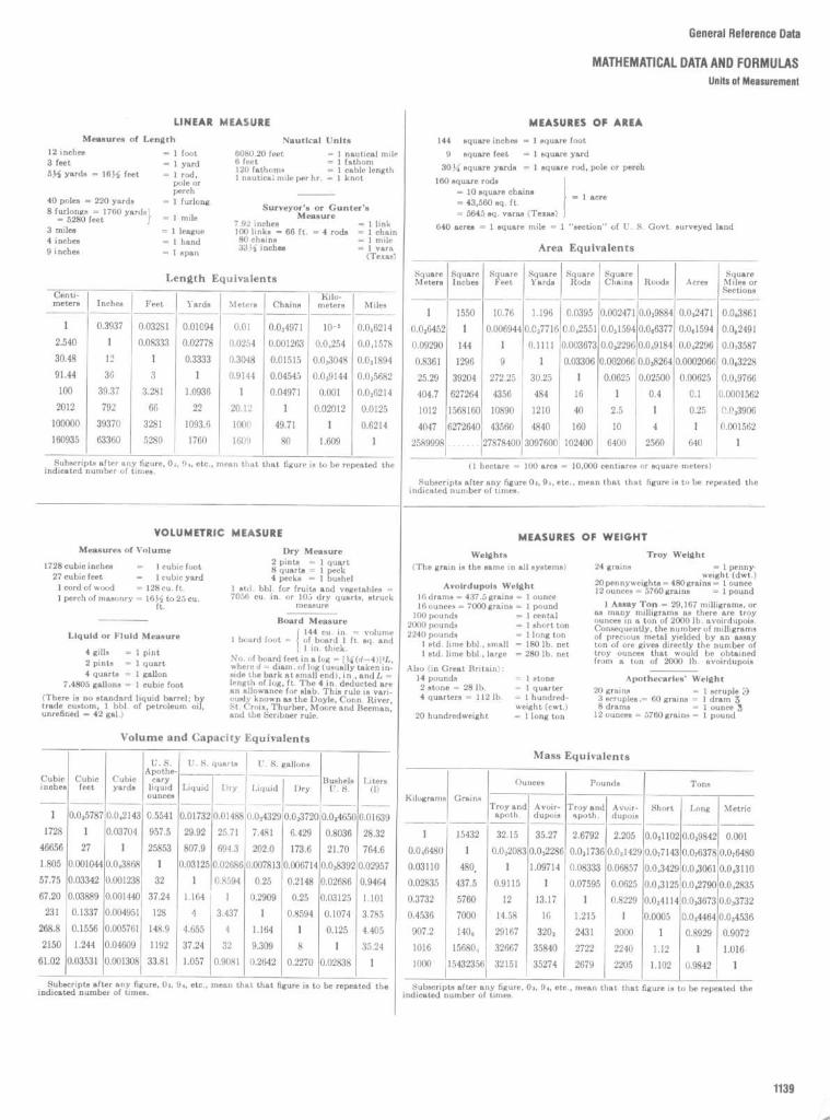
General Reference Data
MATHEMATICAL DATA AND FORMULAS
Units of Measuremeni

General Reference Data
MATHEMATICAL DATA AND FORMULAS
Metric Conversion Tables

General Reference Data
MATHEMATICAL DATA AND FORMULASFraction, Decimal, and Metric Conversion Tables
METRIC CONVERSION FACTORS
METRIC TO AMERICAN
Millimeters - 25 .4 = inches_ Centimeters X 0.3937 = inches
Meters X 39.27 = inchesMillimeters X 0.003281 = feetCentimeters X 0.03281 = feetMeters X 3.281 = feetMeters X 1 .094 = yardsKilometers X 0.621 = milesKilometers X 3280 .7 = feetSquare millimeters - 645 .1 = square inchesSquare centimeters - 6.451 = square inchesSquare meters X 10.764 = square feetSquare kilometers X 247 .1 = acresHectares X 2.471 = acresCubic centimeters - 16 .383 = cubic inchesCubic meters X 35.315 = cubic feetCubic meters X 1.308 = cubic yardsCubic meters X 264 .2 = gallonsLiters X 61 .022 = cubic inchesLiters X 0.2642 = gallonsLiters - 28 .316 = cubic feetHectoliters X 3.531 = cubic feetHectoliters X 2.84 = bushelsHectoliters X 0.131 = cubic yardsHectoliters X 26 .42 = gallonsKilograms X 2.2046 = poundsKilograms _ 1102 .3 = tons
AMERICAN TO METRIC
Inches X 25.4 = millimetersInches X 2.54 = centimetersInches X 0.0254 = metersFeet X 304 .8 = millimetersFeet X 30 .48 = centimetersFeet X 0.3048 = metersYards X 0.9143 = metersMiles X 1.6093 = kilometersFeet - 3280 .7 = kilometersSquare inches X 645.1 = square millimetersSquare inches X 6.451 = square centimetersSquare feet - 10 .764 = square metersAcres - 247 .1 = square kilometersAcres - 2.471 = hectaresCubic inches X 16.383 = cubic centimetersCubic feet - 35.315 = cubic metersCubic yards - 1.308 = cubic metersGallons (231 cu . in .) - 264 .2 = cubic metersCubic inches - 61 .022 = litersGallons X 3.78 = litersCubic feet X 28.316 = litersCubic feet - 3.531 = hectolitersBushels - 2.84 = hectolitersCubic yards - 0.131 = hectolitersGallons - 26.42 = hectolitersPounds - 2.2046 = kilogramsTons X 1102.3 = kilograms

General Reference Data
MATHEMATICAL DATA AND FORMULAS
Areas of Plane Figures

General Reference Data
MATHEMATICAL DATA AND FORMULASFunctions of Numbers
TABLE 20 Functions of Numbers
1000SQUARE CUBE x NO . - DIAMETER
NO. SQUARE CUBE ROOT ROOT LOGARITHM RECIPROCAL CIRCUM. AREA
1 1 1 1 .0000 1 .0000 0.00000 1000.000 3.142 0.78542 4 8 1 .4142 1 .2599 0.30103 500.000 6.283 3.14163 9 27 1 .7321 1 .4422 0.47712 333.333 9.425 7.06864 16 64 2 .0000 1 .5874 0.60206 250.000 12.566 12.56645 25 125 2 .2361 1 .7100 0.69897 200.000 15.708 19.63506 36 216 2 .4495 1 .8171 0.77815 166.667 18.850 28.27437 49 343 2 .6458 1 .9129 0.84510 142.857 21 .991 38.48458 64 512 2.8284 2.0000 0.90309 125 .000 25.133 50.26559 81 729 3.0000 2.0801 0.95424 111 .111 28.274 63.617310 100 1000 3.1623 2.1544 1 .00000 100 .000 31 .416 78.539811 121 1331 3.3166 2.2240 1 .04139 90.9091 34 .558 95.033212 144 1728 3.4641 2.2894 1 .07918 83.3333 37 .699 113.09713 169 2197 3.6056 2.3513 1 .11394 76.9231 40.841 132.73214 196 2744 3.7417 2.4101 1 .14613 71 .4286 43.982 153.93815 225 3375 3.8730 2.4662 1 .17609 66.6667 47 .124 176.71516 256 4096 4.0000 2.5198 1 .20412 62.5000 50.265 201 .06217 289 4913 4.1231 2.5713 1 .23045 58.8235 53 .407 226.98018 324 5832 4.2426 2.6207 1 .25527 55.5556 56.549 254.46919 361 6859 4.3589 2.6684 1 .27875 52.6316 59.690 283.52920 400 8000 4.4721 2.7144 1 .30103 50.0000 62.832 314.15921 441 9261 4.5826 2.7589 1 .32222 47.6190 65.973 346.36122 484 10648 4.6904 2.8020 1 .34242 45.4545 69.115 380.13323 529 12167 4 .7958 2.8439 1 .36173 43.4783 72.257 415.47624 576 13824 4 .8990 2.8845 1 .38021 41 .6667 75.398 452.38925 625 15625 5 .0000 2.9240 1 .39794 40.0000 78.540 490.87426 676 17576 5 .0990 2.9625 1 .41497 38 .4615 81 .681 530.92927 729 19683 5 .1962 3.0000 1 .43136 37 .0370 84.823 572.55528 784 21952 5 .2915 3.0366 1 .44716 35.7143 87 .965 615.75229 841 24389 5 .3852 3.0723 1 .46240 34.4828 91 .106 660.52030 900 27000 5 .4772 3.1072 1 .47712 33.3333 94 .248 706.85831 961 29791 5.5678 3.1414 1 .49136 32.2581 97 .389 754.76832 1024 32768 5 .6569 3.1748 1 .50515 31 .2500 100.531 804.24833 1089 35937 5.7446 3.2075 1 .51851 30.3030 103 .673 855.29934 1156 39304 5 .8310 3.2396 1 .53148 29.4118 106.814 907.92035 1225 42875 5.9161 3.2711 1 .54407 28.5714 109.956 962.113
36 1296 46656 6.0000 3.3019 1 .55630 27 .7778 113.097 1017 .8837 1369 50653 6.0828 3.3322 1 .56820 27 .0270 116.239 1075.2138 1444 54872 6.1644 3.3620 1 .57978 26.3158 119.381 1134 .1139 1521 59319 6.2450 3.3912 1 .59106 25.6410 122.522 1194 .5940 1600 64000 6.3246 3.4200 1 .60206 25.0000 125.66 1256.6441 1681 68921 6.4031 3.4482 1 .61278 24.3902 128.81 1320.2542 1764 74088 6.4807 3.4760 1 .62325 23.8095 131 .95 1385.4443 1849 79507 6.5574 3.5034 1 .63347 23.2558 135.09 1452.2044 1936 85184 6.6332 3.5303 1 .64345 22,7273 138.23 1520.5345 2025 91125 6.7082 3.5569 1 .65321 22 .2222 141 .37 1590.43

General Reference Data
MATHEMATICAL DATA AND FORMULASFunctions of Numbers
TABLE 20 Functions of Numbers (Continued)
1000SQUARE CUBE x
NO . = DIAMETER
NO . SQUARE CUBE ROOT ROOT LOGARITHM RECIPROCAL CIRCUM . AREA
46 2116 97336 6.7823 3.5830 1 .66276 21 .7391 144.51 1661 .9047 2209 103823 6 .8557 3.6088 1 .67210 21 .2766 147.65 1734.9448 2304 110592 6 .9282 3 .6342 1 .68124 20.8333 150.80 1809.5649 2401 117649 7.0000 3.6593 1 .69020 20.4082 153.94 1885.7450 2500 125000 7 .0711 3.6840 1 .69897 20.0000 157.08 1963.5051 2601 132651 7.1414 3.7084 1 .70757 19.6078 160.22 2042.8252 2104 140608 7.2111 3.7325 1 .71600 19.2308 163.36 2123.7253 2809 148877 7.2801 3.7563 1 .72428 18.8679 166.50 2206.1854 2916 157464 7 .3485 3.7798 1 .73239 18.5185 169.65 2290.2255 3025 166375 7 .4162 3.8030 1 .74036 18.1818 172.79 2375.83
56 3136 175616 7.4833 3.8259 1 .74819 17.8571 175.93 2463.0157 3249 185193 7 .5498 3 .8485 1 .75587 17.5439 179.07 2551 .7658 3364 195112 7 .6158 3 .8709 1 .76343 17.2414 182.21 2642.0859 3481 205379 7 .6811 3 .8930 1 .77085 16.9492 185.35 2733.9760 3600 216000 7 .7460 3 .9149 1 .77815 16.6667 188.50 2827 .43
61 3721 226981 7 .8102 3 .9365 1 .78533 16.3934 191 .64 2922.4762 3844 238328 7 .8740 3 .9579 1 .79239 16.1290 194.78 3019.0763 3969 250047 7 .9373 3 .9791 1 .79934 15.8730 197 .92 3117 .2564 4096 262145 8 .0000 4 .0000 1 .80618 15.6250 201 .06 3216.9965 4225 274625 8 .0623 4 .0207 1 .81291 15.3846 204.20 3318.31
66 4356 287496 8 .1240 4 .0412 1 .81954 15.1515 207.35 3421 .1967 4489 300763 8 .1854 4 .0615 1 .82607 14.9254 210.49 3525.6568 4624 314432 8.2462 4 .0817 1 .83251 14.7059 213.63 3631 .6869 4761 328509 8 .3066 4 .1016 1 .83885 14.4928 216.77 3739.2870 4900 343000 8.3666 4 .1213 1 .84510 14.2857 219.91 3848.45
71 5041 357911 8.4261 4 .1408 1 .85126 14.0845 223.05 3959.1972 5184 373248 8.4853 4 .1602 1 .85733 13.8889 226.19 4071 .5073 5329 389017 8.5440 4 .1793 1 .86332 13.6986 229.34 4185.3974 5476 405224 8.6023 4 .1983 1 .86923 13.5135 232.48 4300.8475 5625 421875 8.6603 4 .2172 1 .87506 13.3333 235.62 4417 .86
76 5776 438976 8.7178 4 .2358 1 .88081 13.1579 238.76 4536.4677 5929 456533 8.7750 4 .2543 1 .88649 12.9870 241 .90 4656.6378 6084 474552 8.8318 4 .2727 1 .89209 12.8205 245.04 4778.3679 6241 493039 8.8882 4 .2908 1 .89763 12.6582 248.19 4901 .6780 6400 512000 8.9443 4 .3089 1 .90309 12.5000 251 .33 5026.55
81 6561 531441 9.0000 4.3267 1 .90849 12.3457 254.47 5153.0082 6724 551368 9.0554 4.3445 1 .91381 12.1951 257.61 5281 .0283 6889 571787 9.1104 4.3621 1 .91908 12.0482 260.75 5410.6184 7056 592704 9 .1652 4.3795 1 .92428 11 .9048 263.89 5541 .7785 7225 614125 9 .2195 4.3968 1 .92942 11 .7647 267.04 5674.50
86 7396 63605 9 .2736 4 .4140 1 .93456 11.6279 270.18 5808.8087 7569 65850' 9 .3274 4 .4310 1 .93952 11 .4943 273 .32 5944.6888 1744 681472 9 .3808 4 .4480 1 .94448 11 .3636 276 .46 6082.1289 7921 9 .4340 4 .4647 1 .94939 11 .2360 279 .60 6221 .1490 8100 729D0 :î
7049619 .4868 4 .4814 1 .95424 11 .1111 282 .74 6361 .73

Credits1 . Planning and Design of Interior Spaces
Residential SpacesPages 5-28 :
House and Garden's Complete Guide to Interior Decoration, edited by RichardsonWright, Simon and Schuster, New York, 1942 (copyright renewed 1970 by The Condé Nast Publica-tions Inc.) .
Pages 29-42:
Gottshall, Franklin H., How to Design and Construct Period Furniture, Bonanza Books,New York, 1989 .
Page 43 :
The House andHome Book of Interior Design, McGraw-Hill, New York, 1976.Page 49 :
NewSpaces for Learning, Educational Facilities Lab, New York, 1966 .Pages 56-60:
Ramsey, Charles George, and Harold Reeve Sleeper, Architectural Graphic Standards,2d Edition, Wiley, New York, 1936 .
Pages 62, 63, 81, 83, 84, 196, 197, 199 :
Architectural Forum, October 1937 .Pages 65-68, 71, 72, 96, 118-124, 164:
Thompson, Robinson, Toraby .Page 69 :
Verna Cook Salomonsky, Architect .Page 70 :
Ulrich Franzen, Architect ; Selected Architectural Details, Reinhold, New York .Pages 73-76:
Parrish Hadley Associates .Page 80 :
U.S. Department of Housing and Urban Development, Washington, D.C .Pages 82, 104, 105, 152:
House Planning Handbook, 2d Edition, MWPS-16, Midwest Plan Service,Ames, Iowa, 1988 (reproduced with permission).
Pages 85, 86 :
Lehigh Furniture Company.Pages 88, 89, 153, 154:
Manual ofAcceptable Practices, U.S . Department of Housing and Urban De-velopment, Washington, D.C .
Pages 89, 201 :
Internal Spaces of the Dwelling, Canada Mortgage and Housing Corporation,1984 .
Pages 90-93, 125-127, 135, 166, 167:
Bromley/Jacobsen .Page 94 :
Knobloch, Philip G., Good Practice in Construction, Pencil Points Press, New York,1931 .
Page 95 :
Comparative Architectural Details, Pencil Points Series /Francis Y. Joannes, Architect),1935 .
Page 97 :
Gensler Associates ; ISD; Bromley/Jacobson .Pages 98, 99 :
American Architect and Architecture, January 1937 .Pages 100, 101, 149, 150, 206:
Panero, Julius, and Martin Zelnik, Human Dimension & InteriorSpace, Whitney Library of Design/Watson-Guptill Publications, New York, 1979 .
Pages 102, 103, 202-204:
Time-Saver Standards: A Manual of Essential Architectural Data, F. W.Dodge Corporation, New York, 1946 .
Pages 106-108:
Kohler .Pages 109, 110, 114, 170 (bottom) :
Eller.Pages 111-113, 115, 116, 170 (top) :
American Standard .Pages 117, 194, 198:
Hombostel, Caleb, Architectural Detailing Simplified, Prentice-Hall, EnglewoodCliffs, N.J ., 1986 .
Pages 128, 156 :
A Design Guide for Home Safety, U.S. Department of Housing and Urban Devel-opment, Washington, D.C., 1972 .
Page 129:
Space Design Group.Pages 130, 131 :
Marble Institute of America.Pages 132-134, 136:
Handbook for Ceramic Tile Installation, Tile Council of America, Princeton,N.J ., 1987 .
Pages 137-140, 181-186:
Adaptable Housing, Office of Policy Development and Research, U.S . De-partment of Housing and Urban Development, 1987 .
Pages 141, 142, 179, 180:
New York City Building Code .Pages 143, 146, 147, 178:
Uniform FederalAccessibility Standards, 1985-494-187, U.S . GovernmentPrinting Office, Washington, D.C ., 1985 .
Pages 144, 187:
Handbook for Design, Veterans Administration, Washington, D.C.Pages 145, 148, 165, 168, 169, 188, 189, 191, 192:
Jerry Caldari, Architect.

Page 151 :
De Chiara, Joseph, and John Hancock Callender (eds .), Time-Saver Standards for Build-ing Types, 2d Edition, McGraw-Hill, New York, 1980 .
Page 155:
Formica Corporation .Pages 157, 158, 172, 173:
Merillat.Pages 159, 160:
St. Chartes.Pages 161-163:
Triangle Pacific Corporation .Page 171 :
Euroflair by Frigidaire .Pages 174, 175:
Manual of Millwork, Woodworking Institute of California .Page 193:
Pencil Points, April 1934 .Page 195:
Putnam Rolling Ladder Company.Pages 196, 200, 205 :
De Chiara, Joseph (ed.), Time-Saver Standards for Residential Development,McGraw-Hill, NewYork, 1984 .
Page 199:
Design Solutions, Architectural Woodworking Institute, Summer 1989 .Page 207 (top):
Council Notes, University of Illinois .Page 207 (bottom):
Architectural Forum, October 1938 .Page 208 (left) :
General Services Administration .Page 208 (right) :
Illinois Agricultural Experiment Station .Pages 209, 213, 214:
Pencil Points, 1935 .Pages 210 (top), 215:
Bertram Bassuk, FAIA .Pages 210 (bottom), 211 (top), 212:
ISD.Page 211 (bottom) :
Chartes D. Flayhan Associates .Page 216:
Schulte.Pages 217-220:
Closet Maid Systems.
Office SpacesPages 223, 224, 231, 232, 241, 249, 260:
Panero, Julius, and Martin Zelnik, Human Dimension & In-terior Space, Whitney Library of Design/Watson-Guptill Publications, NewYork, 1979 .
Pages 225, 226, 243-245:
Pulgram, William L., and Richard E. Stonis, Designing the Automated Of-fice, Whitney Library of Design/Watson-Guptill Publications, New York, 1984 .
Pages 236, 237, 240, 259, 266, 267, 271:
Gensler Associates .Pages 238, 263, 268, 269, 274, 275, 298, 299, 303, 304 (top):
Chartes D. Flayhan AssociatesPages 239, 264, 277 :
ISD.Page 242:
Intergraph Corp., Interiors .Pages 246-248:
Interiors, November 1985.Pages 250, 251 :
Lehigh Furniture Company.Page 252 :
Howe Furniture Corp.Pages 256, 283-295:
Steelcase.Page 256 :
Panero Zelnik Associates .Pages 257, 258, 270, 272:
Design Solutions, Architectural Woodworking Institute, Spring 1986 .Page 262 :
Will Ching, Planning and Design .Page 265 :
Marble Institute of America.Pages 273, 276:
Bertram Bassuk, FAIA.Page 278:
De Chiara, Joseph, and John Hancock Callender (eds.), Time-Saver Standards For Build-ing Types, 2d Edition, McGraw-Hill, New York, 1980.
Pages 279, 280, 281:
Herman Miller.Page 282:
Vecta.
Hospitality SpacesPages 307, 308:
Architectural Record, 1943 .Page 312:
Architectural Forum ; Manual ofAcceptable Practices, U.S . Department of Housing andUrban Development, Washington, D.C.
Pages 316, 317, 330, 377-380:
Davies, Thomas D., Jr ., and Kim A. Beasley, Design For Hospitality:Planning for Accessible Hotels and Motels, Nichols Publishing, New York, 1988 .
Pages 318, 322,346,347:
Panero, Julius, and Martin Zelnik, Human Dimension & Interior Space,Whitney Library of Design/Watson-Guptill Publications, New York, 1979 .
Pages 319, 325, 326, 328, 338, 359, 365, 368, 369:
Toni Chi and Associates .Pages 319, 320:
Panero Zelnik Associates.Pages 321, 329, 332,363,364,366,367,369 :
Jerry Caldari, Architect.Pages 323, 324, 331 :
Space Design Group.Pages 327, 333, 334:
Interiors, October 1985 .Pages 335-337 :
Gensler Associates .Page 339 :
Chartes D. Flayhan Associates .PA.A Q eat-145v
Isn

Pages 357, 358, 362 :
Interiors, July 1985 .Page 360:
Selected Architectural Details, Reinhold, NewYork .Pages 361, 369, 370, 373, 381, 382:
Design Solutions, Architectural Woodworking Institute, Spring1990 .
Pages 371, 372:
Hochheiser-Elias Design Group.Pages 374, 376:
De Chiara, Joseph, and John Hancock Callender (eds .),Time-Saver Standards forBuilding Types, 3d Edition, McGraw-Hill, New York, 1990 .
Retail SpacesPages 387-389:
Panero, Julius, and Martin Zelnik, Human Dimension & Interior Space, Whitney Li-brary of Design/Watson-Guptill Publications, New York, 1979.
Pages 390, 394, 400:
Selected Architectural Details, Reinhold, New York .Pages 391, 392, 396-399:
Design Solutions, Architectural Woodworking Institute, Winter 1987,Summer 1988 .
Pages 393, 401-411:
Walker Group/CNI.Page 395:
Marble Institute of America.Pages 412-417:
Panero Zelnik Associates .Pages 418-422:
PAM International Co ., Inc.
Public Restrooms, Toilets, and CoatroomsPage 425:
NewYork City Building Code .Pages 427-430:
General Services Administration .Pages 431-438, 465:
Bertram Bassuk, FAIA .Page 439 :
William Morgan, FAIA .Pages 440-445:
DeChiara, Joseph, Handbook of Architectural Details for Commercial Buildings,McGraw-Hill, New York, 1980 .
Page 446:
Toni Chi and Associates .Pages 447, 448:
American Sanitary Partition Corporation .Pages 449-451 :
Access America, Architectural and Transportation Barriers Compliance Board,Washington, D.C ., 1980 .
Page 452:
Uniform Federal Accessibility Standards, 1985-494-187, U.S . Government Printing Office,Washington, D.C ., 1985 .
Page 453:
A& J Washroom Accessories .Pages 454-457:
Parker/Nutone.Pages 458, 459:
American Specialties, Inc .Pages 461-463:
Railex .Page 464:
Jerry Caldari, Architect .
2 . Construction Details and FinishesPages 471, 472, 518, 542, 547, 660-664, 727 :
Time-Saver Standards: A Manual of Essential Archi-tectural Data, F. W. Dodge Corp ., New York, 1946 .
Pages 470, 517 :
McQuade, Walter (ed.), Schoolhouse, Simon and Schuster, New York, 1958 .Pages 473, 475-477:
New York State Building Code .Pages 474, 478, 565:
Hornung, William J., Reinhold Data Sheets, Reinhold, New York, 1965 .Pages 480, 487, 489, 491, 497, 500-502, 512-515, 522-526, 532, 540, 541 (top), 577-579, 581-588, 601,606, 608, 609, 614, 617, 629, 630-632, 648, 657, 658, 692 (bottom), 698, 708, 714, 721, 722, 751 (bot-tom) :
Bertram Bassuk, FAIA .Pages 481-483, 484 (bottom), 490 (bottom), 629, 649, 651 (top), 652, 754, 755 (top):
ISD.Pages 484 (top), 485, 488, 492, 493, 495, 496, 529, 530, 534, 564, 653, 654, 656, 751 (top), 752,753:
Gensler Associates .Pages 486, 580, 605, 659, 669 (top):
William Morgan, FAIA .Pages 490 (top), 650, 651 (bottom) :
Charles D. Flayhan Associates .Pages 491, 754 (top), 755 (bottom) :
Michael Lynn Associates .Pages 494, 543, 548, 549, 627, 628, 634:
Anderson, L. 0., Wood-Frame House Construction, Depart-ment of Agriculture Handbook No . 73, U.S. Government Printing Office, Washington, D.C ., 1970 .
Pages 498, 550:
Wood Frame Design, Western Wood Products Association .Pages 499, 504, 758, 759 :
Panero Zelnik Associates .Pages 503, 508, 510, 616, 633, 665, 704,705,738:
Knobloch, Philip G., Good Practice in Construction,Pencil Points Press, New York, 1931 .
Pages 505, 506, 561-563:
Handbook for Ceramic Tile Installation, Tile Council of America, Princeton,N.J ., 1988 .

Pages 507, 554-560:
American Olean Tile .Pages 509, 520, 715, 733-736:
Marble Institute of America.Page 519:
Radford, William, Architectural Details, R. D. Radford, Chicago, 1938 .Pages 521, 749, 750:
Callender, John Hancock (ed.), Time-Saver Standards forArchitectural DesignData, 6th Edition, McGraw-Hill, New York, 1982.
Pages 527, 528 (top):
Walker Group/CNI .Pages 531, 551 :
Roppe Rubber Corp .Page 533 :
American Architect and Architecture, May 1932 .Pages 535-539:
National Terrazzo and Mosaic Association, Inc.Page 541 :
Buckingham Virginia State Co .Page 544:
American Parquet Association.Page 545:
Hoboken Wood Flooring Co.Page 546:
Tarkett .Page 553 :
Franciscan Tile Company.Pages 566-571, 574-576, 589-599, 607:
Hollow Metal Manufacturers Association.Pages 572, 670, 671, 706:
Jerry Caldari, Architect.Page 573 :
Methods and Materials of Commercial Construction.Page 600 :
New York State Construction Handbook.Pages 602, 603, 67"84, 687, 689, 695, 696, 710, 711, 742:
Baker, Earl P., and Harold S. Langland,Architectural Metal Handbook, National Association of Ornamental Metal Manufacturers, Washing-ton, D.C., 1947 .
Page 604 :
General Services Administration .Page 610 :
Eggers Industries.Pages 611, 675:
Raymond, Antonin, Architectural Details, Architectural Book Publishing Co ., Inc.,1947 .
Pages 612, 666:
Burbank, Nelson L., House Construction Details, 3d Edition, Simmons- BoardmanPublishing Corp ., New York, 1952 .
Page 615 :
Thompson, Robinson, Toraby.Page 618 :
Progressive Architecture, April 1971 .Pages 620-626:
Comparative Architectural Details, Pencil Points Series (Frank J. Forster, Architect),1935 .
Pages 637-640:
Schlage.Pages 641-643:
New York City Building Code .Pages 644-647:
Sweet's Catalog.Pages 655, 707, 769, 771-773:
Toni Chi and Associates.Page 667:
Design Solutions, Architectural Woodworking Institute .Page 668:
Simon B. Zelnik, FAIA.Page 672:
Interiors, April 1985 .Page 673:
Feirer, John L., Cabinet Making and Millwork, Chartes A. Bennet Co ., Peoria, III .Page 674:
Ascente.Page 676, 712:
Selected Architectural Details, Reinhold, New York .Pages 677, 685, 686, 688, 690, 691, 692 (top), 693, 694, 697, 699-703, 709:
National Association ofArchitectural Manufacturers.
Page 713:
NewYork City Housing Authority.Page 716:
Slate Institute .Page 717:
Manual of School Planning, New York City Board of Education.Pages 718, 719, 723:
Uniform Federal Accessibility Standards, 1985-494-187, U.S . GovernmentPrinting Office, Washington, D.C ., 1985 .
Page 720:
Lapeyre Stair .Page 726:
Farmers Bulletin # 1889, U.S . Department of Agriculture, Washington, D.C ., 1971 .Pages 728, 729:
Handbook of Successful Fireplaces, Dunley Bros . Co ., Cleveland, Ohio, 1961 .Page 731 :
Pencil Points (Ely Jacques Kahn, Architect), October 1938 .Page 732:
Pencil Points (Richard Neutra, Architect), 1938.Page 736:
Pencil Points (Frank Forster, Architect) .Page 737:
Pencil Points (Walker & Gillette, Architects).Pages 739-741 :
Architectural Paneling, Inc .Pages 743, 744, 778:
General Electric Company.Pages 745-748:
Nessen Lamp Company.Pages 756, 757:
Horton Lees Lighting Designs, Inc.Pages 760-762:
Space Design Group.Pages 763, 764:
Bromley/Jacobsen .Page 765:
Architectural Lighting, September 1987 .Pages 766, 768:
Roberts Step Lite Systems, Inc.Pages 767, 770, 774:
National Cathode Corp.Page 775:
Philips Lighting Co .Pages 776, 777:
Just Bulbs Ltd.

3 . Architectural WoodworkPages 781, 7855-787 :
Time-Saver Standards: A Manual of Essential Architectural Data, F. W. DodgeCorp ., New York, 1946 .
Pages 782-784, 788-797, 801-803:
Woodworking Institute of California .Pages 798-800, 872, 873, 877, 879, 881-883:
Architectural Woodwork Institute .Page 804:
Leroy P. Ward, Architect.Page 806:
Comparative Architectural Details, Pencil Points Series (Frank J. Forster, Architect), 1935 .Page 807:
Comparative Architectural Details, Pencil Points Series (Evans, Moore, Peterson &Woodbridge, Architects), 1935 .
Pages 812, 813, 839 (right), 842, 845, 847, 848, 849 (bottom), 853-856, 859, 862-864:
Design Solu-tions.
Pages 814, 815:
Space Design Group; ISD.Page 816:
Selected Architectural Details, Progressive Architecture (Perkins & Wills, Architects) .Pages 808-810, 851 :
Knobloch, Philip G., Good Practice in Construction, Pencil Points Press, NewYork, 1931 .
Page 818:
Thompson, Robinson, Cecil, Inc.Pages 819-823, 829, 831A35 :
Bertram Bassuk, FAIA .Pages 824, 828, 836-838 :
Chartes D. Flayhan Associates .Page 825:
ISD.Page 826, 827, 830, 839 (left), 846:
Gensler Associates .Pages 840, 841 :
Winebarger Church Furniture .Page 843:
Panero Zelnik Associates .Page 844:
Hochheiser-Elias .Pages 849 (top), 852:
General Services Administration .Page 850:
Roger H. Ballard, Architect .Page 857:
Hyde and Shepherd, Architects .Page 858:
Howard and Frenaye, Architects .Pages 860, 861 :
Comparative Architectural Details, Pencil Points.Page 865:
Manual of Millwork, Woodworking Institute of California .Pages 86670, 886:
Architectural Paneling, Inc.Pages 871, 873-878, 880-885 :
Camden Window and Millwork .Pages 887-889:
Joyce, Ernest, Encyclopedia of Furniture Making, Sterling Publishing Co ., Inc., NewYork, 1987 .
Pages 890-902:
Hafele.
4 . SpecialtiesPages 906-915:
Everett Conklin and Susan Korner, in Alpern, Andrew led.), Handbook of SpecialtyElements in Architecture, McGraw-Hill, New York, 1982 .
Pages 916-922, 923 (top):
TheGreen Scene, National Park Service, U.S . Department of the Interior,Washington, D.C ., 1973 .
Pages 923 (bottom), 924-926, 929, 930:
Engel/GGP.Pages 927, 928:
Hornbostel, Caleb, Architectural Detailing Simplified, Prentice-Hall, EnglewoodCliffs, N.J ., 1986 .
Pages 931-935, 940, 941, 943, 9455-948:
Fred T. Knowles, in Alpern, Andrew led.), Handbook of Spe-cialty Elements in Architecture, McGraw-Hill, New York, 1982 .
Pages 936-939:
Designers Sign Company/Frank Rispoli .Pages 942-944:
U.S . Department of Transportation, Washington, D.C .Pages 949-957:
Jerome Menell, in Alpern, Andrew led.), Handbook of Specialty Elements in Archi-tecture, McGraw-Hill, New York, 1982.
Pages 961-964:
Hussey Seating Company.Pages 965, 966, 968-976:
J.G . Furniture Systems.Page 967:
Design Guide for Music and Drama Centers, Department of the Army, Washington, D.C.,1981 .
Pages 977-997:
A Design Guide for Improving Residential Security, U.S . Department of Housingand Urban Development, Washington, D.C ., 1973 .
Pages 998, 1002, 1028 :
TheHouse and Home Book of Interior Design, McGraw-Hill, New York, 1979 .Pages 999, 1013, 1014 :
Halse, The Use of Color in Interiors, McGraw-Hill, New York, 1968 .Pages 1000, 1001, 1003-1012:
Derieux, Mary, and Isabelle Stevenson, The Complete Book of Inte-rior Decorating, Greystone Press, New York, 1950 .
Pages 1023-1026:
Anderson, L. 0., Wood-Frame House Construction, Department of AgricultureHandbook No . 73, U.S . Government Printing Office, Washington, D.C ., 1970.
Page 1016 :
McQuade, Walter led.), Schoolhouse, Simon and Schuster, New York, 1958.Pages 1017-1020:
Sweet's Catalog.Page 1021 :
Marvin Windows.

Pages 1056-1059:
Kirsch.Page 1060 :
Armor Elevator .Pages 1061-1064:
Dover Elevator Co.Pages 1065, 1066, 1102 :
Uniform Federal Accessibility Standards, 1985-494-187, U.S . GovernmentPrinting Office, Washington, D.C ., 1985 .
Page 1067 :
Panero Zelnik Associates .Pages 1067-1074:
Outdoor Sports Facilities, Departments of the Army, Navy, and Air Force, Wash-
ington, D.C .Page 1068 (top):
Mace, Ronald L., An Illustrated Handbook ofthe Handicapped Section ofthe NorthCarolina State Building Code, Raleigh, N.C ., 1974.
Pages 1075-1078:
Cutter Manufacturing.Page 1079 :
Phillips and Brooks, Inc.Pages 1080-1086:
Baker, Earl P., and Harold S. Langland, Architectural Metal Handbook, NationalAssociation of Ornamental Metal Manufacturers, Washington, D.C ., 1947 .
Pages 1087-1089:
Brown Manufacturing Co .Page 1090 :
Bertram Bassuk, FAIA .Pages 1091-1096:
Pittcon Softforms.Pages 1097-1099:
Alvarado Manufacturing Co .Pages 1100-1101 :
Haws.
5. General Reference DataPages 1106-1109:
Ballast, David Kent, Architect's Handbook ofFormules, Tables, and MathematicalCalculations, Prentice-Hall, Englewood Cliffs, N.J ., 1988 .
Pages 1110, 1111 :
Panero, Julius, and Martin Zelnik, Human Dimension & Interior Space, WhitneyLibrary of Design/Watson-Guptill Publications, New York, 1979.
Pages 1112,1113:
Access America, Washington, D.C .Pages 1114 (top):
Sister Kenny Institute .Pages 1114 (bottom), 1115-1118 :
Uniform FederalAccessibility Standards, 1985-494-187, U.S . Gov-ernment Printing Office, Washington, D.C ., 1985 .
Pages 1119, 1120 :
Woodson, W. E., Human Factors Design Handbook, McGraw-Hill, New York,1981 .
Page 1121 :
Building for People, U.S . Department of Commerce, Washington, D.C .Pages 1123-1125:
Foster, Norman, Practical Tables for Building Construction, McGraw-Hill, NewYork, 1963 .
Page 1128 :
Halse, The Use of Color in Interiors, McGraw-Hill, NewYork, 1968 .Page 1129 :
Hombostel, Caleb, Architectural Detailing Simplified, Prentice-Hall, Englewood Cliffs,N.J ., 1986 .
Pages 1130, 1131 :
Derieux, Mary, and Isabelle Stevenson, The Complete Book of Interior Decorat-ing, Greystone Press, NewYork, 1950.
Pages 1132,1134:
Steelcase.Page 1133 :
National Electrical Code Book, McGraw-Hill, New York, 1981 .Page 1135 :
Indiana Limestone Institute .Pages 1137, 1138 :
Wing, Chartes, The Visual Handbook of Building and Remodeling, Rodale Press,1990 .
Pages 1139-1142:
Time-Saver Standards: A Manual of Essential Architectural Data, F. W. DodgeCorp ., New York, 1946.

IndexAccessible bathrooms, 143-148, 317, 380,
449-452Accessible design, 317, 330, 377-380, 449-
452,1065,1066,1068,1102(See also Barrier-free design)
Accessories, 1075-1102chalkboards, 1090column covers, 1091-1096drinking fountains, 1100-1102fireplaces, 742grilles, 1080-1086guards, protection, 1087-1088handrails, 1089key cabinets, 1078letter boxes, 1075lockers, parcel, 1078mail chutes, 1078mail collection boxes, 1076mail drops, 1077telephone booths, 1079turnstiles, 1097-1099water coolers, 1100-1102
Accessory heights, toilets, 117, 128Acoustical partitions, 494-498Adaptable bathrooms, 137-142Adaptable kitchens, 181-185Aisle types, center-cross, 961-976Altars, 840Anthropometric data :
bars, 346, 347bathrooms, 100, 101closets, 206conference room, 249electronic workstations, 241, 242library, 190reference data, 1110-1113retail spaces, 387-389
Architectural woodworking, 804-865altars, 840bar sinks, 818bars, 346, 347, 358-362, 364-366, 368-373,
864base cabinets, 837benches, 849book and prayer shawl cabinets, 832, 833bookcases, 808-812cabinet doors, 797casework, 788-794clothes storage, 835coat closet, 835corner cupboards, 806, 807cornices, 856-861counters :
teller's, 396-400, 855
Architectural woodworking, counters (Cant.) :work, 824-826
display cases, 819-823, 829, 862, 863door finishes, 865file countertop, 836finishes, 865hidden door, 853lecterns, 843-846lobby display, 829mouldings, 856-861overfile cabinets, 827, 828paneling, 804, 805, 860, 861pantry cabinet, 839pass-through vision panel, 275, 276pews, 841planter/storage cabinets, 831raised panel door, 794, 799, 801, 854sanctuary door, 842sash, 801screen, 850storage shelves, 834storage walls, 816tables, conference, 847, 848trader's watt, 814, 815wardrobes, 817window seat, 851windows, 802, 803wood paneling, 804, 805wood railing and gate, 852wood stairs, 665-671, 673
Area requirements, 1106-1109Areas of planes, 1142Astragals, 875Audio-visual systems, 950-960equipment, 48, 953, 960front projection, 952optical design factors, 953planning guidelines, 952-955projection rooms, 951-960rear screen, 952remote control, 953sound system, 953
Auditorium seating, 961-976arrangements, 966, 970-976chair dimensions, 962, 964, 965continental, 961design considerations, 961, 966, 968, 969dimensions, 962, 964, 965layouts, 961-976row length, 962row spacing, 963screen sightlines, 969screen sizes, 952seat widths, 962, 965
Auditorium seating (Cant.) :sightlines, 950, 951, 961terminology, 967visibility, 969
Awning windows, 1016, 1018
Backbar, 347Badminton court, 1073Bank teller's counters, 396-400, 855Banquet seating, 252Banquette seating, 313-321design criteria, 313-315, 318details of, 319-321
Bar configurations, 348-356Bar details, 346, 347, 358-373Bar sink cabinet, 818Bar stool spacing, 348-356Barrier-free design :bathrooms, 143-145, 317, 380drinking fountains, 1102elevators, 1065kitchens, 178-189ramps, 723restrooms, 449-452stairs, 718, 719toilets, 449-452water coolers, 1102wheelchairs, 1114(See also Accessible design)
Bars, 346-373anthropometric data, 346, 347backbar, 347bar cabinet, 361bar shapes, planning criteria, 348-356bar stool spacing, 348-356bottle steps, 363, 368, 369clearances, public side, 347cocktail tables, 347customer activity zone, 347dimensions of, 348-356elevations of, 357, 362, 367front- and backbar, 348-356, 358, 359, 364,
366-369glass racks over, 365, 370leaning, 347planning criteria, 346, 347,358-362,
364-366,368-373plans, elevations, and sections, 358-373sections through, 346, 347,356-362,
364-366,368-373standing, 347working drawings of, 358-373
Base cabinets, 789, 792, 794, 837Base cap mouldings, 877

Base details, 532, 533, 538Base mouldings, 532, 533, 786Base types, 532, 533, 538carpet, 532ceramic, 532marble, 533quarry tile, 532resilient, 532, 551stone, 533terrazzo, 538vinyl, 532wood, 533
Baseboards, 532, 533, 786Basketball court, 1069, 1071Bathrooms, 100-148accessible design of, 143-148, 380, 449-452accessories, 117, 128adaptable design of, 137-142anthropometric considerations, 100, 101barrier-free, 143-148, 380, 449-452bathtub and shower details, 132-134bathtub types, 113, 114bathtub walls, tile, 132, 133, 136bidet, 116compartmented plans, 103, 105controls, 128countertops, 125-127, 130, 131custom designs, 106-108five-fixture plans, 103four-fixture plans. 103, 119, 120half, 102, 121heights, 117, 128lavatory types and dimensions, 109-112planning data and fixture arrangement, 100,
101plans, elevations, and details, 118-124powder room, 102, 121three-fixture plan, 102, 118tile tubs, 132-134two-fixture plan, 102typical plans and fixture arrangements,
102-105vanities, 125-127, 129-131watercloset types and dimensions, 115, 116wheelchair accessible, 144-148, 380, 449-452whirlpool bath details, 113, 135(See also Restrooms and toilets)
Bathtubs :grab barssizes, 113, 114tile, 132, 133, 136types, 113, 114walls, 132, 133, 136wheelchair accessible, 143-148, 317, 380,
449-452whirlpool, 113, 135
Bedroom closets, 96-99, 220Bedrooms, 87-99
built-in furniture, 90-95, 97clearances and arrangements, 87-89closets, 96-99furniture, 56planning data, 87-89walk-in closets, 96
Beds and mattresses, 46Benches, 841, 849-851, 929, 930
Bi-fold doors, 513Bidet types and dimensions, 116Billiard tables, 197Blinds, woven wood, 1054Bolts, 898, 1138Bookcases, 808-812Booth seating, restaurant, 316Brackets, curtain, 1047Bricks :bonds, 478floors, 540joints, 478partitions and walls, 473-478types, 478
Bulbs, tight, 775-777Butt hinges, 887, 890
Cabinet doors, 797Cabinet hardware, 887-901
castors and glides, 901coat and hat hooks, 901drawer runners, 897flap stays, 895latches, 898lid stays, 896locks, 899magnetic and spring catches, 898shelf supports, 900wardrobe rails and supports, 901
Cabinet types:base, 837book and prayer shawl storage, 832, 833coat closets, 835corner cupboard, 806, 807display, lobby, 829file, 285-289kitchen, 154-169overfile, 827, 828pantry, 839storage, 290
Cabinets, kitchen, 149-169clearances above work surface, 149, 150,
153-156dimensions for, 156-164styles of, 159, 160
Cafeteria counters, 329, 333-338, 340-345Carousel coat storage, 461, 462Carpet :
area conversion, 1122construction, 1128edgings, 531stair finishings, 714transitions, 522, 523, 525-527, 529, 530
Casement/hopper windows, 1017Casement windows, 803Casework, 788-794custom, 789-791, 797definitions, 788drawer details, 791economy, 789-791, 797flush overlay, 792-794premium, 789-791, 797
Cashier counter, 825Casings, 878-880Ceilings, 641-659
acoustical, 641-643, 647-650, 654-659
Ceilings (Cons.) :concealed spline, 647curved, 651, 652exposed T grid, 642exposed Z bar, 643gypsum board, 644lay-in tile, 642, 643, 646, 654, 658, 659plaster, 645, 648, 652, 657plywood finish, 648reflected ceiling plan, 659suspended,641-653suspended, concealed spline, 642vaulted, 651, 652
Ceramic floors, 552-563Ceramic tile :
ceilings, 561concrete stabs, 562, 563expansion joints, 563floors, 540, 561-563installation details, 561-563shapes, 507soffits, 561stairs, 561wall finishes, 505-507wood subfloors, 561
Chair dimensions, 278-281Chair rails :marble, 508wood, 870, 883
Chairs, office, 59, 278-281Chairs, residential, 5-45, 51-55, 5920th century classic, 51-55
Chalkboard, 1090Checkroom systems, 460-463Children's furniture, 44Closers, door, 591, 593, 594Closets :bedroom, 206-209, 213, 214, 218children's, 218foyer/front entry, 219housekeeping/utility room, 217linen, 216master bedroom, 206-209, 213, 214, 218narrow and deep, 207pantry, 217reach-in, 207shallow and wide, 207split, 206, 207standard, 207, 208U-shaped walk-in, 206, 207walk-in, 206, 207wardrobe, 817
Closets/storage areas, 206-220anthropometric considerations, 206details, 835female, 206garment dimensions, 208male, 206rod lengths and heights, 207shelf heights, 206, 208shelf space and lighting, 207walk-in, 206, 207wire shelving systems, 216-220
Clothes dimensions, hanging, 208Coat shelf details, 210-212, 463, 835carousel, 461, 462

Coat shelf details (Coielectric, 461, 462fixed/stationary capacities, 461, 463rotating reels, 461, 462
Coatroom systems, 461-463Coatrooms, 460-465
coat capacity, 462floor area requirements, 460plans, elevations and sections, 464public, 460-465shelves for, 465
Cocktail tables, 347Cold cathode, 774Collection boxes, 1076Color, 999-1013areas and samples, 1001effects of lighting on, 1014hues, 998-1002intensities, 998-1002Munsell system of color, 1002reflective values, 1013values, 998-1002
Color combinations, 1000, 1001charts, 1000
Color families :blue, 1010, 1011green, 1008, 1009orange, 1005red, 1003, 1004violet/purple, 1012yellow, 1006, 1007
Color reflectivity, 1013values, 1013
Color schemes, 1000, 1001planning, 998
Color terms, 1001Color theory, 998-1014Color wheel, 1002Colors :
accented, 998analog or related, 998, 1000color wheel, 999combinations, 1001complementary or contrasting, 998cool, 1000monochromatic, 998neutral, 1000primary, 998safety color guide, 1013secondary, 998tertiary, 998value scale, 999warm, 1000
Columns:capitals and entablatures, 1135covers, 1091-1096fireproofing of, 514, 515
Computer floors, 564, 565Computer workstations, 241-248Concealed hinges, 892Conference rooms, 248-259anthropometric data, 249clearances for, 249credenzas, 259heating unit, enclosures in, 259layouts, 254, 255
Conference rooms (Cont.) :planning data, 249-255seating capacities, 24255, 283, 284table sizes, 249-255, 283, 284
Conference tables, 283, 284bases, 256boat-shaped, 251-254circular, 249, 250, 253, 254clearances around, 249details of, 256-258edge details of, 256race track, 252rectangular, 251, 252room sizes for, 254, 255round, 249, 250, 253, 254shapes of, 250-253, 283, 284sizes, 249-255, 283, 284wood edge treatments, 256
Containers, plant, 831, 912Continental seating, 961Corner cupboards, 806, 807Corner guards, 1087, 1088Cornices, 856-858, 861(See also Mouldings)
Couches, 5, 9, 13, 17, 21, 25, 26, 45, 57, 77-79Counters :
cafeteria, 329, 333-338, 340-345cashier, 335, 337, 825condiment, 339, 341, 342file, 298, 299, 303file countertop, 824-828kitchen, 154-169, 792, 794lavatory, 125-127, 130, 131lunch, 322pick-up, tray, 337, 341plastic laminate, 174retail, 387-389, 391, 392, 394-402salad bar, 334, 340, 343, 344self-service, 329servery, 343, 345service, 338serving, 340-344sink, 175telephone, 825teller's, 396-400, 855walkup, 825word processing, 825work, 824-826
Courts :badminton, 1073basketball, 1069, 1071handball, 1070paddle tennis, 1072shuffleboard, 1074tennis, 1070, 1072volleyball, 1073
Cove lighting, 413-417, 751-759cold cathode, 752, 774mechandise display, 407-409, 412-417retail stores, 407-409, 412-417
Cove mouldings, 881Covering capacities and quantities :
carpet, 1122floor tile, 1123paint, 1123panel, 1126
Covering capacities and quantities (Cont.)wood flooring, 1127
Credenzas, 826, 830, 855Crown mouldings, 866-868, 871, 872Cupboard, corner, 806, 807Curtains, 5, 6, 9, 10, 13, 14, 17, 18, 20-22,
24-26,28,1027-1041caf6, 1033, 1036colonial style, 1029Federal style, 1029headings, 1043pocket, 1027rods, 1048-1051ruffled, 1033, 1034, 1036shirred, 1034(See also Draperies)
Decibel scale for sounds, 1121Decimal conversion tables, 1141Desks, 7, 8, 12, 16, 20, 24, 27, 30, 58lamps, 744, 747reception, 260, 262-272, 855registration, 381-383workstations, 223-235
Dining room/ period furniture, 6, 7, 10, 11, 13,15, 18, 19, 22, 23, 26-29, 31, 36-38, 40-41
Dining room seating, 316Dining room sizes, 83, 85Dining rooms, 80-86
furniture arrangements, 80furniture clearances, 80-84furniture dimensions, 50, 56seating, 85, 86tables, 80-86
Display cases, 387-393, 402-404, 408, 409,819-823,829,862,863
cosmetic, 391, 402-404feature watts, 412-417island, 392jewelry, 391refrigerated, 392shelving, 407-409, 412-414, 422shirt, 391television, 405, 406
Display systems:binning, 419rack, 419-421wall, 418, 419, 422
Door frames, 571-587, 607-609Door hardware, 568, 569, 589-598, 634-643,
1129installation of, 569, 1129location of, 1129
Door jambs :hollow metal, 571, 573-582, 585, 586marble, 629wood, 581-586, 608
Door schedules, 570-572Door trim, 854Doors, 566-641, 842, 853, 854
acoustical, 610bank vault, 605bi-fold, 513casement, 612closers, 591, 593, 594construction details, 610

Doors (Cont.) :edges, 599entrance, 618-628exterior, 613, 617-628fire-protected, 600flush, 795, 796frames, 571-587, 607-609
hollow metal, 571, 573-582, 585, 586French, 612hardware, 568, 569, 589-598, 634-664, 1129hidden, 853hinges, 568, 598hollow metal, 566-599laminated, 566lead-lined, 610lightproofing, 576, 606paneled, 612, 613, 615, 616particle board, 610raised panel, 842, 853, 854saddles, 522-528sanctuary, 842sash, 801schedules, 570-572screen, 611secret, 616, 808shoji, 611sizes, 568sliding, 601, 611sound proofing, 576, 606stave, 610stile and rail, 610thresholds, 602-604wood, 573, 587, 588, 600, 610-628, 632-634wood-clad, 582, 584, 608
Double hung windows, 802Down lighting, 749, 750Draperies, 5, 6, 9, 10, 13, 14, 17, 18, 20-22,
24-26,28,1027-1042bishop sleeve, 1035cascade, 1037colonial, 1029colors, 1028design, 1028Directoire, 1030fabric, 1028Federal, 1029finials, 1048full-length, 1029-1032, 1034, 1035Georgian, 1030hardware, 1046-1051headings, 1043, 1044historical styles, 5, 6, 9, 10, 13, 14, 17, 18,
20-22,24-26,28holdbacks, 1034hooks, 1048late Georgian, 1030late Victorian, 1031mid-19th-century Victorian, 1031mounts, 1047neo-Greek, 1031panel widths, 1051period styles, 1028-1032rings, 1048rods, 1049, 1050single pleated, 1036stackback requirements, 1058
Draperies (Cont.) :swags, 1029-1031, 1038-1040, 1042upholstery, 1028
Drawers:capacities of, 286-291card file, 291details, 785, 789-791, 797glossary, 292, 293insert, 286lateral file, 287, 287legal file, 285letter file, 285linear capacities of, 286-291with shelves and add-on cabinets, 289vertical file, 285, 286
Dresser, 97Drinking fountains, 1100-1102Drywall partitions, 481-496
Electrical :amperage ratings, 1132, 1134appliance loads, 1134circuits, 1134receptacle location, 1133requirements, 1132-1134
Electronic media storage, 294, 295Electronic workstations, 241-248
administrative, 244, 245analyst/programmer, 245anthropometrics, 241, 242area requirements, 243-245computer requirements, 241, 242data retrieval, 243managerial, 245planning data, 241-248secretarial, 243shared tasks, 243square footage for, 243, 245task profiles, 243-245trading desk details, 246-248word processing, 244
Elevators :barrier-free considerations, 1065, 1066, 1068doors, 1064geared traction, 1060gearless traction, 1061hydraulic, 1061low and mid rise, 1061passenger,1060-1066planning guidelines, 1060security of, 978, 989-991selection of, 1060traction high rise, 1062, 1063wheelchair lifts, 1068
Escalators, 1067Exit doors, security of, 989
Fabrics :characteristics and suitability of, 1130, 1131types, 1130, 1131
Face out display systems, 413, 414, 418Family/recreation rooms, 196-199arrangement and clearances, 196, 197recreational activities, 196, 197
File cabinets, 285-289card file drawers, 281
File cabinets (Coot.) :dimensions of, 285-287drawer types in, 285-289insert drawers, 286lateral, 287, 288legal file drawers, 285letter file drawers, 285linear capacities in, 286overfile, 286roll-away, 286vertical, 285weights of, toad, 287
File storage, details of, 298, 299Fire doors, 6009----__Fireplaces, 68-71, 724-742accessories for, 742construction details of, 725, 729dimensions of, 725-729, 804flue sizes of, 726-729mantels, 68-71, 520, 521, 730-741, 804, 859planning data, 724-729
Fireproofing, 514, 515Fixture heights plumbing, 117Flagstone, 520Floor:raised, 564, 565sound rated, 548-550
Floor construction :details, 516-565computer floors, 564, 565marble, 521slate, 541terrazzo, 535-541wood, 542-550wood on concrete stab, 547wood strip flooring, 543
sound insulation, 548-550Floor finishes :
bases, 532, 533, 786brick, 540ceramic tile, 519, 540, 541, 552-568characteristics of, 517edgings, 531marble, 541parquet, 544-546quarry tile, 541resilient tile, 541, 551saddles, 522-526slate, 541terrazzo, 53 55-541transitions, 527-530wood, 541, 544, 547
Floor lamps, 743, 745Floor patterns :ceramic tile, 519, 552-563,marble, 520, 521stone, 534tile, 519
Flushbolts, 596Folding table hinges, 891French doors, 801French paneling, 805Functions of numbers, 1144Furniture arrangements, living room, 61Furniture clearances :
dining rooms, 50, 56, 80-84

Furniture clearances (Copt.) :living room, 50, 57, 63
Furniture dimensions :audio-visual equipment, 48bedroom, 56beds and mattresses, 46bookcases, 808-812chairs, 45, 51-55, 59chaise lounges, 45chests, 58children's furniture and tables, 44convertible sofas, 47couches, 5, 9, 13, 17, 21, 25, 26, 45, 57,
77-79desks, 58dining room, 50, 56highboys, 58love seats, 45lowboy, 58mattresses and beds, 46pianos, types and sizes, 199secretary, 58settees, 57sofa beds, 47sofas, 5, 9, 13, 17, 21, 25, 26, 45, 57, 77-79tables, 44, 45, 50, 60,television sets, 5020th century classic chairs, 51-55wall beds, 47waterbeds, 47
Furniture, furnishings, and equipment,278-304
chair dimensions, 278-281chair types, 278-281conference tables, 282-284counter tops with base cabinets, 303desks, 7, 8, 12, 16, 20, 24, 27, 30, 58file cabinets, 285-289file counter tops, 298, 304kitchen, compact, 304lounge seating, 282office pantry details, 300-303overfile cabinet, 299reception seating, 282storage cabinets, 290
Furniture glides, 902Furniture hardware, 890-901Furniture types/styles, 5-43American, 17th century colonial, 5-8, 29, 30American, 18th century colonial, 9-12, 29, 30American, 18th century Federal, 13-16American, late 18th-early 19th century
Federal, 13-16Brothers Adam, 39, 40, 17-24Chippendale, 36colonial, 5-16, 24, 30Directoire and Empire, 25-28Duncan Phyfe, 31English 16th century Jacobean, 32English, 17th century Jacobean, 33English 17th century William and Mary, 34English 18th century Georgian, 17-20, 36English 18th century late Georgian, 21-24,
37, 38English 18th century Queen Anne, 35Federal, 13-16
Furniture types/styles (Cons.) :French, 17th and 18th century Louis XIV,
XV, and XVI, 41Georgian, 17-24, 36-38Hepplewhite, 37Jacobean, 32, 33late Georgian, 39, 40Louis XIV, XV, and XVI, 41Queen Anne, 35Sheraton, 38Spanish, 42table of, 43William and Mary, 34
Furring of :columns, 488, 491walls, 483, 484, 498, 499wood, 497
Garage doors, 992-995Gardens :
drainage, 911interior, 910large, 910planting procedures, 910-913small, 910(See also Plants ; Plantscaping)
General offices, 223-230area allocations, 225, 226basic workstations, 223-226groupings, 224minimum square footage, 225, 226multiple workstations, 227-230open workstations, 225, 226screened workstations, 225, 226square footage for, 225, 226task profites, 225, 226U-shaped workstation, 224
Glass door cabinet hinges, 894Glass partitions, 492Glass shelving details, 402-404, 407, 408, 409,
413,414Gliding windows, 1019Grab bars, 458, 459Grilles, 1080-1086Guards, watt protection, 1087, 1088Guestroom plans, 374-380
accessible, 377-380Gymnasium, 1071Gypsum board partitions, 481-496
Handball courts, 1070Handrail details, 665-669, 671, 672, 681, 682,
692, 707, 718, 719Hardware :
bolts, 898, 1138cabinet, 887-902catches, 898closet, 901coordinators, 595door, 568, 569, 589-598, 634-640door closers, 593-594door holders, 593-594door stop, emergencyfire exit, 595flush bolts, 596furniture, 887
Hardware (font.) :hand of lock, 635hinge locations, 568hinges, 589-591, 634, 887-894hospital door latch, 597installation in wood door, 534locations of, 634, 1129lock functions, 635lockset types and descriptions, 592, 636-640panic, 595wood door, 534, 592, 636-640
Headings, drapery, 1043, 1044Hearths, 726-729Highboy, 58Hinge types:anchor, 589butt, 887, 890concealed, 892flap, 891, 895folding table, 891,full mortise butt, 589, 590full surface butt, 589, 590full surface-swing clear, 590glass door, 894half mortise, 589, 590half mortise butt, 589, 590half surface butt, 589, 590hospital "swing" clear, 590invisible, 590mitred, 892pivot, 888, 889, 893
Hinges, 887-894Holdbacks, 1045, 1046Hollow metal door frames, 571-582, 585,
586anchorage of, 575, 577details, 571, 573, 577-586light and soundproofing of, 576profiles, 574, 575, 576, 599typical jamb installations, 571, 573, 577-586schedules, 570-572wood and metal, 582, 584
Hollow metal door hardware, 569, 589-598Hollow metal doors, 566-599
construction types, 567designs of, 568, 571dimensions of, 568edge treatments, 599hardware, 569, 589-598hinge locations, 568, 598laminated construction, 566sizes of, 568steel stiffened, 566
Hospitality spaces, 307-383bars, 346-373guestroom plans, 374-380hotel room plans, 374-380hotels, 374-383restaurants, 307-345
Hotel roam plans, 374accessible, 377-380
Hotels, 374-383accessible bathrooms, 143-148, 317
449-452seeess,t e
z a-s 377-38Cguestroom pians, 374-383

Hotels (Copt.) :reception desk, 384registration desks, 381-383room layouts, 374-380
Indoor recreation, 1069-10'13Indoor trees, 907Interior plants, 906-930
Jalousie window, 1018Jambs :
hollow metal, 571, 573-582, 585, 586marble, 629wood, 581-586, 608
Joinery details, 781-803Joinery types, 781-803
stile and rait, 503, 610, 798, 799, 805, 813Joint, 781-784
butted, 781, 782cabinet, 785-793characteristics, 781furniture, 781-784mitered, 781, 782shiplapped, 781, 782terminology, 783tongue and groove, 781-786typical, 781-784
Kitchen layouts :adaptable, 178-189broken U,151-153corridor, 151-153L-shaped, 151-153U-shaped, 151-153
Kitchens :accessible, 178-189adaptable, 181-185anthropometric data, 149, 150appliances, 171-173barrier free design, 178-189cabinet details, 154-169cabinet types and dimension, 156--'.64clearances, 149, 150, 153-156compact, details of, 304countertops, 174, 175heights and equipment, 153layouts of, 151-153microwave cabinets, 163minimum counter frontage, 153planning information, 149, 150-155plans, elevations and details, 176, 177sink types and dimensions, 170space criteria, 153storage and cabinets, 154, 155storage requirements, 154, 155typical layouts, 151, 152wheelchair accessible designs, 178-189
Ladders, 720, 721Lamp (bulb) types, 774-778Lamps (portable), 743-748
desk, 744, 747floor, 743, 745minimum shade dimensions, 743-748personal, 743, 744table, 744-746
Lamps (portable) (font.) :wall-mounted task, 748
Laundry room locations, 202, 203Laundry/bathroom combinations, 202Laundry/kitchen combinations, 204Laundry/sewing combinations, 200-205Laundry/sewing rooms, 200-205
sewing center clearances, 205washer/dryer arrangements, 200, 201
Lavatory clearances, 100-103Lavatory counter details, 441-446Lavatory countertops, 441-446Lavatory heights, 100, 101, 450wheelchair accessible, 450
Lavatory types and dimensions, 109-112Lectern, 843-846Letterboxes, 1075Lettering typestyle, 947,948Libraries/studies, 190-196anthropometric data, 190bookcases, 80"12capacities of, 190details of, 192-195heights of, 190plans, elevations, and details, 191-194rolling ladders for, 195volumes per linear foot, 190
Lid stays, 895Light cove details, 413-417Lighting, 743-778, 1014
cold cathode ceiling mounted, 774, 752cove, 413-417, 751-759feature watts, 412-417handrail lighting, 765lighted column, 771-773merchandise, 407-409, 412-417miscellaneous, 760-764nosings and treads, 766-769planning data, 743, 744, 749, 750, 774-778retail stores, 407-409, 415-417skylite lighting, 770stair lighting, 766-769
Lighting levels, 750industrial, 778office, 778plants, 915residential, 750store, 778
Lighting plan, 659Lighting types:
cornice, 749downlighting, 749, 750valence, 415-417, 749
Living rooms, 61-79bars in, 72circulation, 62conversation area, 62-64fireplaces, 69-71floor plan of, 67, 68, 73-76furniture arrangments, 61furniture clearances, 63furniture dimensions, 50media cabinet details, 65, 66planning considerations, 61-63plans, elevations, and details of, 67, 76sofas, 77-79
Living rooms (Coot.) :television viewing areas, 64
Locks, 592bored, 592bored cylindrical deadlock, 592functions of, 631-640furniture, 899mortise, 592mortise deadlock, 592unit, 592
Locks, latches, and deadlocks, 592, 636-640Lockset functions, 636-640Lockset types and descriptions, 592, 636-640Lounge seating, 261, 281, 282Lowboy, 58Lunch counters, 322
Mail chutes, 1078Mail drops, 1077Mailboxes, 1076Mantels, 68-71, 520, 521, 733, 735, 736,
738-741marble, 733-735wood, 736-741, 804
Marble :ceilings, 509details, 68-71, 520-521, 733, 735, 736,
738-741patterns, 520, 521walls, 508-510
Marble flooring, 519, 520, 521Marble jambs, 629Marble stairs, 715Masonry partitions and walls, 473-480Mathematical data and formulas, 1139-1144Mattress types and sizes, 46Mattresses and beds, 46Measurement conversion tables, 1139-1144Media rooms, 65, 66Medical symbols, 940Men's toilet room, 427, 433, 436, 437, 440Metal stud and gypsum board, 481-496Metric conversion tables, 1140Mirrors, triple, 410Modular panel conversion chart, 1126Mortar beds, 132, 541, 561-563Mouldings, 856-858, 861, 866-886backbands, 873baluster, 884base, 876, 877base cap, 877base shoe, 876brackets, wood, 886brick, 874casings, 878, 879, 880chair rail, 870, 883clam shell, 885colonial, 885corner guards, 875cove, 881crown, 866, 867, 868, 871, 872deep sculpt, 866, 867door trim, 869, 870floor, 876half round, 884handrail, 884

Mouldings (Cons.) :lattice, 885mirror, 870miscellaneous, 873-875panel, 870, 882picture, 870, 873pilaster, 874round, 824sanitary, 875, 885sash, 875, 885step, 873stop, 885trim, 870(See also Cornices)
Mounting heights, telephone, 1079Mounts, curtain rods, 1047Munsell color system, 1002
Nail types and sizes, 1136, 1137Newels and railings, 665, 666, 673, 692, 693,
694, 699, 703, 705Nosings, stair lighting in, 766-769Nosings and treads, abrasive, 687, 688, 691,
715,722
Office spaces, 223-304conference rooms, 248-259electronic workstations, 241-248furniture, furnishings, and equipment,
278-304general offices and multiple workstations,
223-230pass-through windows, 512private, 231-240room arrangements, 233-235reception areas, 260-277workstation types, 223-232
Open workstations, 225, 226Overfile cabinet, 827, 828
Paddle tennis court, 1072Panel conversion chart, 1126Panel mouldings, 503Paneled door :
details of, 784, 799, 801, 854frame parts of, 784
Paneled wainscot, 503, 799Paneled walls, 798, 799, 800, 801, 804, 805,
813, 814, 842, 856-861, 860, 861Paneling, 500-504, 804, 805, 860, 861
French, 804, 805raised, 503, 800wood, 500-504, 736, 737
Panic hardware, 595, 596Pantry cabinets, 839Parquet flooring, 544-546Partitions and wall finishes, 469-515Partition types :metal stud and gypsum board, 481-496toilet, 447, 448
Partitions, 470-499acoustical, 494-498brick, 473-478concrete block, 480, 483drywall, 481-496fire-rated, 495
Partitions (Coot.) :glass, 492gypsum board, 481-496interior, 470-499marble, 508-510masonry, 473-478, 480, 483miscellaneous types, 493piers, 473plaster, 470-473, 475-477, 508-511slate, 511sound transmission, 494-498stone, 479, 508-511wood stud, 472, 473, 494, 498
Pass-through windows, 275, 276People, distance relationships, 1119, 1120Period furniture :American, 17th century Colonial, 5-8, 29, 30American, 18th century Colonial, 9-12, 29,
30American, 18th century Federal, 13-16American, late 18th century-early 19th
century Federal, 13-16Brothers Adam, 39, 40Chippendale, 36Colonial, 5-16, 29, 30Directoire and Empire, 25-28Duncan Phyfe, 31English 16th century Jacobean, 32English 17th century Jacobean, 33English 17th century William and Mary, 34English 18th century Georgian, 17-20, 36English 18th century, late Georgian, 21-24,
37, 38English 18th century Queen Anne, 35Federal, 13-16French, 17th and 18th century Louis XIV,
XV, and XVI, 41French, late 18th century-early 19th century,
25-28, 41Georgian, 17-24Hepplewhite, 37Jacobean, 32, 33late Georgian, 39, 40Louis XIV, XV, and XVI, 41Queen Anne, 35Sheraton, 38Spanish 16th and 17th century, 42table of, 43William and Mary, 34
Pews, 841Pianos, 199photometrics, 766
Picture mouldings, 870, 873Pivot hinges, 888, 889, 893Pivot windows, 1019, 1022Plant containers, 831, 912Planters, 831
diameters, 906-909, 912window, 927, 928
Planting, 911, 912, 916-928bed material, 411, 912, 916-923details, 923-928medium, 911, 912, 916-923standards, 906-915
Plants, 906-930design guidelines for, 906-915
Plants (Cont.) :diameters of, 906-909floor, 907heights of, 906-909high light level, 915light and sun requirements, 916-923low tight level, 915medium light level, 915procedures for planting, 910-913requirements, 906-915soil requirements, 911, 912, 916-923spacing, 906-909species, 907specifications, 910temperature requirements of, 913-916texture, 906trees, indoor, 907typical, 916-923water and humidity requirements, 916-923water requirements, 915
Plantscaping, 906-930design guidelines, 906-915specifications, 910
Plaques, 936-939Pleated shades, 1053measurements, 1058
Pleats, 1051, 1043, 1044Plumbing fixtures, 107, 109-116Pools, 912Pot sizes, 906-909, 912Projection, 950-960
distances, 953front, 952rear, 952
Projection room layouts, 950-960Projection screens, 949-960
Quarry tile, 541
Railings, 665-669, 671, 672, 681, 682, 692, 707,718
Raised floors, 564-565Raised paneling, 503Raised wood panels, 503Ramps, 723
barrier-free, 718, 719, 723Rear projection, 952Receptacles, electrical, 1133Reception areas:planning data, 260, 261receptionists' workstation in, 262-276seating arrangements, 261
Reception desks, 260, 262-272, 855hotel, 381-384
Reception rooms : 260-277seating, 261
Reception window detail, 273-276, 512Recreation, indoor, 196, 197Reference data, general, 1105-1144Reflected ceiling plans, 760Reflective values, color, 1013Registration desks, 381-383Residential spaces, 5-219bathrooms, 100-148bedrooms, 87-99closet/storage areas, 206-220

Residential spaces (Coot.) :dining rooms, 80-86family/recreation rooms, 196-199kitchens, 149-189laundry/sewing rooms, 200-205libraries/studies, 190-195living rooms, 61-79period furniture, 5-43
Resilient floors, 541, 551Restaurants, 307-345
accessible design, 317, 330banquette seating, 313-316, 318-321booth seating, 316cafeteria/servery, 333-345condiment cabinet, 339, 341, 342counter details, 333-337
counter details, 323-327, 329, 331, 333-338,340,343-345
counters, 323-327dining room seating, 316host cabinet, 338lunch counters, 322design criteria, 322
maitre d' station, 338salad bar serving counter, 840, 844seating, 313-316, 318-321self-service counter, 329servery counter, 843, 845service counter, 338table spacing, 308-316trash counter, 338tray pickup, 341
Restrooms and toilets, 425-465accessible design, 317, 430, 449-452accessories, 453-457accessory heights, 426-429, 431, 433,
435-441,450,452clearances for wheelchair access, 317,
449-452(see Bathrooms; Hotels)
fixture requirements, fixture count, 425grab bar configurations, 458, 459lavatory counter details, 442-446lavatory heights, wheelchair accessible, 450plans and elevations, 430-441plumbing data, 425plumbing fixture heights, 426-429, 431, 433,
435-441public, 425-465show facility for accessibility, 147toilet accessories, 453-459toilet stall details, 447, 448toilet stalls, accessible, 449-452vanity details, 441-446wheelchair accessible, 317, 430, 449-452women's toilet/powder room, 430, 434-437
Retail spaces, 387-422anthropometric considerations, 387-389back island details, 401banks, 396-400binning, 419counter heights, 387-389, 391, 392, 394-402department stores, 401-423display cases, 387-393, 402-404, 408, 409,
862,863faceouts, 413, 414, 418
Retail spaces (Cont.) :feature walls, 412-417garment capacities, 418lighting, 407-409, 412-417, 759planning data, 387-389rack display systems, 420-421refrigerated case, 392sales counters, 387-389, 391, 392,
394-402shelving, 407-409, 412-414, 422shops, 387-395showcases, 387-393, 402-404, 408, 409storefronts, 390triplicate mirror, 410valance and cove lighting, 415-417wall display systems, 418, 419
Risers, 671, 686-688, 708, 713-716, 719Rock formations, 912Rod display system, 421Rods :
drapery-curtain, 1048-1050traverse, 1050
Roll-in showers, 140Rolling ladders, 195Row length and spacing, 961-969, 970-976
Saddles, 522-528under doors, 522-528
Salad bar counter, 340Sates counters, 387-389, 391, 392, 394-402Sash, profites of, 801Screens:
projection, 952shoji, 611
Screw types, 1138Seat widths, 968Seating arrangements, 966, 970-976auditorium, 961-976standard, 961
Seating:continental, 961multiple, 966
Secondary entries, security of, 989Security, 977-997alarms, exit, 995bars, grills, and gates, 988closers, 980control of grounds, 977, 978cylinders, 981, 983, 984doors, 977-986electronic systems, 994, 996, 997elevators, 978, 989-991exit doors, secondary, 989fire doors and fire stairs, 977garage doors, 992-985general control guidelines, 977, 978hardware, 979-986hinges, 980lighting, 993lobby spaces, 977locks, 981, 986, 987mailbox rooms, 992, 993multifamily dwelling, 977public spaces of multiple dwelling, 977secondary entries, 989skylights, 988
Security (Cont.) :sliding doors, 984window and hardware, 978, 986-988
Security alarms, 994-997Serving counter, 329, 333-338, 340-345Settees, 5, 9, 17, 25, 33, 57Sewing equipment, arrangement of, 205Sewing machines, heights and clearances, 205Sewing rooms, 205planning of, 205
Shades, window, 1052-1054tamp, 743-746
Shelf and hanging pole, 835Shelf edge, 826, 830, 834, 835Shelf heights :
closets, 835storage, 826, 834
Shelf light details, 298overhead file storage details, 827, 828
Shelf supports, 900Shelf types:
coat, 277coatrooms, 465phone, 277wall, 277wire basket and shelving system, 216-220,
419Showcase types:cosmetic display, 391, 402-404island display, 392jewelry, 391, 401refrigerated, 392shirt display, 391
Shower floor details, 132, 133Shower seat design, 132Shower wall details, 132Showers:grab bars for, 140, 142, 144, 147roll-in, 140, 144, 147wheelchair accessibility, 140
Shuffleboard court, 1074Shutter details, 1057Shutters, 1055-1057Sign types, 931-948area designation-wall mounted plaques, 937ceiling hung, 937code, 936counter top, 939cut letters, 939design criteria, 931-935desk top, 939directional, overhead, 937directional, wall mounted, 937framed wall-mounted plaques, 938room identifier, 938
Signage :celing hung, 937checklist for, 934, 935counter top, 939desk bar, 939desk top, 939directional, 937flag mount, 939framed wall-mounted plaques, 938room identifier, wall mounted, 938symbols, 940-946

Signage (Cons) :type and mounting heights, 936-939
Signage and graphics, 931-948Signage system design criteria, 931-936, 949graphic symbols, 940-946mounting heights, 936mounting materials, 937standard sizes, 936-939types, 936-939
Sinks, kitchen, 170Skylights, lignting, 770State flooring, 541State stairs, 716Sliding windows, 1019Sofa beds, 47Sofa dimensions, 45Sofas, 77-79Sofas, chairs, tables, and stools, 45Soffits (see Ceilings)Sound control partitions, 494-498Sound insulation, floor construction, 548-550Sound insulation and transmission details,
494-498,548-550Sound levels, 1121Sound transmission, partitions, 49"98, 1121floor construction, 548-550
Space planning area requirements, 1106-1109Specialties, 903-1102
audio-visual systems, 949-960auditorium seating, 961-976chalkboards, 1090color theory, 998-1014column covers, 1091-1096drinking fountains, 1100-1102elevators, 1060-1068fireplaces, 742guards, protection, 1087-1088grilles, 1080-1086handrails, 1089indoor recreation, 1069-1074key cabinets, 1078letter boxes, 1075lockers, parcel, 1078mail chutes, 1078mail collection boxes, 1076mail drops, 1077plantscaping, 906-930security, 977-997signage and graphics, 931-948telephone booths, 1079turnstiles, 1097-1099watercoolers, 1100-1102window treatments, 1015-1059
Spiral stairs, 674, 676, 709, 710Sports, indoor, 1069-1074Stair finishes :
carpeting, 714ceramic tile, 561concrete, 713, 714, 722marble, 715state, 716terrazzo, 539, 708, 712, 714wood, 665-671
Stair lighting, 766-769Stairs :
barrier-free design data, 718, 719
Stairs (Cont.) :circular, 675, 711classes of, 677clearances, 660-664, 686critical dimensions, 660-664, 686details of, 665-672, 678-784, 687-699,
703-708,712-716,721,722floor to floor heights, 660handrail heights, 664handrails, 664-673, 692-702, 717, 718, 765headroom, 660, 664layout of, 664length of, 686, 661-663lighting of, 766-769minimum width of, 661nosings and treads, 664, 687, 688, 691, 708,
713-716,722,766-769number of risers, 660, 662, 663oval, 674, 676, 709, 710pitch of, 664planning data, 660-664, 677, 717platform, 683riser calculations, 660spiral, 674, 676, 709, 710steel, 670, 671stringers, 689, 690treads, 687-688, 719types, 682, 683
circular, 674-676, 709-711concrete, 672, 712-714double L, 662L-shaped, 662, 663ladders, 720, 721oval, 675scissor, 713spiral, 674-676, 709-711steel, 678-683, 722straight run, 662U-shaped, 663, 717
width, 661-663, 685wood, details of, 665-671, 673
Stairway layouts (see Stairs)Standards and brackets, 422STC (sound transmission classifications),
494-498floor construction, 548-550
Steel stairs, 670, 671details of, 670, 671
Storage :closet, 826, 834, 835coatroom, 461-463electronic media, 294, 295overhead file, 827, 828registration desks, 381-384residential, 206-220
Storage cabinets, 290dimensions of, 816glossary of, 292, 293wardrobe, 817
Storage components, 292, 293Storage shelves, 834Storage walls, 816Stores :department, 401-422shops, 387-395
Straight run stairs, 662
Stringers, steel, 666, 667, 671, 678, 680-686,692-694,703-708
Strip flooring, 1127estimating of wood, 1127
Study, 190-194Suspended ceiling types, 641-659concealed spline, 647miscellaneous details, 653-655perimeters and drops, 656
Suspension system types, 641-643Swags, 1029-1031, 1038-1040, 1042Symbols:commercial, 941, 942medical, 940recreation/sports, 445travel, 943, 944universal, 946
Tables, 44, 50, 60banquet, 252boardroom, 847, 848conference, 283, 284design criteria for restaurants, 312dining room, 80-86restaurant. 307-316
Table arrangements, restaurants, 307-311Table lamps, 744Table sizes:
billiards, 197conference room, 249-255, 283, 284ping pong, 197pool, 197spacing in
Tack sizes, 1136Task tights, wall-mounted, 748Telephone stations, 277, 1079Telephone :
clearances, 1079, 1118mounting heights, 1079
Television viewing areas, 49Teller's counters, 855Tennis court, 1070, 1072Terrazzo, 536-540
base, 538flooring, 536, 537, 540stairs, 539
Theater seating, 961-976Thresholds, 522-528Tiebacks, 1045, 1046Tile walls, 132-134, 505-507Toilet accessories, 143-148, 317, 380, 449-459Toilet partitions, 447, 448Toilet stalls :
accessible, 449grab bars, 143-148, 449, 452, 458, 459
Trader's wall, 814, 815Trading desk details, 246-248Treads, 671, 686-688, 708, 713-716
barrier-free, 719cement, 713, 714, 722concrete, 683, 686-688marble, 687, 715metal, 687state, 716terrazzo, 708, 714wood, 671, 687

Trees, indoor, 907Trim (see Mouldings)Turnstiles, 1097-1099Typeface styles, 947, 948
Units of measurement, 1139, 1140
Valance and cove lighting, 749Vanities, 125-127, 129-131countertop details, 125-127, 130, 131
Veneer :marble, 508, 509state, 511
Vertical blinds, 1059Vertical circulation (see Elevators)Vinyl cove base, 532, 551Volleyball court, 1073
Wainscot :flat paneled, 798-800marble, 508-510slate, 511wood, 500-502, 805
Waiter station, 328Wall areas of rooms, 1124, 1125Walt beds, 47
wall board partitions, 481-496Wall finishes, 500-511ceramic tile, 505-507marble, 508-510paneling, 500-504slate, 511wood, 500-504
Wall-mounted task lights, 748Wall paneling :
stile and rail, 503wallpaper area conversion, 1123
Wall protection guards, 1087, 1088Wall types (see Partitions)Wall unit details, private offices, 236-239Wallpaper covering, 1123-1125Walls:
marble, 508-510slate, 511terrazzo, 539
Washer/dryer arrangements, 200, 201Waterbeds, 47Waterclosets, 115, 116wheelchair access, 143-148, 317, 380,
444-452grab bars for, 143-148, 458, 459
Wheelchair :accessible bathrooms, 143-145, 317, 380,
449-452adaptable kitchens, 181-185clearances for, 1114-1118elevators, 1065lifts, 1068restaurants, 317, 330
Wheelchair (Cont.) :terminology, 1114
Whirlpool baths, 113, 135Window bars, grilles and gates, 1080-1086Window treatments, 1015-1059
brackets, 1047curtains, 1027-1041draperies, 1027-1041guidlines, 1058, 1059mounts, 1047shades,1052-1054shutters, 1055, 1056
Window types, 1015-1026austral, 1020awning, 1016, 1018bottom hinged, 1017casement, 1015, 1024, 1025casement hopper, 1017custom shapes, 1021double hung, 1015, 1016, 1019, 1022, 1024,
1025dual vent, 1019gliding, 1019Gothic, 1021hopper, 1017, 1018jalousie, 1018metal, 1018, 1020oval, 1021pivot, 1019, 1020projected, 1018reversible, 1020round top, 1021side hinged, 1017sliding, 1019special, 1020stationary, 1023top hinged, 1018two-light, 1022wood, 1017-1026
Windows, 1015-1026pass-through, 275, 276reception, 273-276, 512security of, 978, 986-988
Windows and hardware, 1015-1026Wire shelving systems, 216-220Women's toilets, 430, 434-437Wood :board feet of, 1127door frames, 608, 609floor construction, 542-550flooring types, 544-547joinery details, 781-787paneling, 661, 804, 805, 860parquet, 544-546railing and gate, 852railings, 665-671stairs, 665-671, 673strip flooring, 543windows, 802, 803
Woodwork details . 804-865attars, 840bar sinks,818bars, 346, 347, 358-362, 364-366, 368-373,
864base cabinets, 837benches, 849book and prayer shawl cabinets, 832, 833bookcases, 808-812cabinet doors, 797casework, 788-794clothes storage, 835coat closet, 835corner cupboards, 806, 807cornices, 856-861counters, teller's, 855counters, work, 824-826, 836, 855display cases, 819-823, 829, 862, 863door finishes, 865drawers, 791file countertop, 836finishes, 865hidden door, 853lecterns, 843-846lobby display, 829overfile cabinets, 827, 828moulding, 856-861paneling, 804, 805, 860, 861pantry cabinet, 839pass-through vision panel, 275, 276pews, 841planter/storage cabinets, 831raised panel door, 794, 799, 801, 854sanctuary door, 842sash, 801screen, 850storage shelves, 834storage walls, 816tables, conference, 847, 848teller's counters, 855trader's wall, 814, 815wardrobes, 817window seat, 851windows, 802, 803wood paneling, 804, 805wood railing and gate, 852wood stairs, 665-671, 673work counters, 824-826
Workstation types, 223-232basic, 223-226electronic, 241-248anthropometrics of, 241, 242
executive, 231, 232general, 223-230multiple, 227-229receptionist, 260trading desks, 246, 247trading tables, 248wood stud partitions, 472, 473, 494, 498

About the Editors
JOSEPH DE CHIARA is a practicing architect andcity planner in New York City . He has taught atColumbia University, Pratt Institute, CooperUnion, the New York Institute of Technology,and the State University of New York atFarmingdale. He is coauthor of Time-SaverStandards for Site Planning and the author ofHandbook of Architectural Details forCommercial Buildings and Time-SaverStandards for Building Types, all published byMcGraw-Hill. De Chiara received a Bachelor ofArchitecture degree from Pratt Institute and aMaster's degree in Urban Planning fromColumbia University .
JULIUS PANERO, AIA, ASID, is a practicingarchitect, interior designer, and Professor ofInterior Design at the Fashion Institute ofTechnology in New York City . He has taughtinterior design for the past 32 years and was aformer chairperson of the interior designdepartment at FIT. A graduate of Pratt Institute,where he received a Bachelor of Architecture,and Columbia University, where he received aMaster of Science in Urban Planning, Panero isa member of the American Institute ofArchitects and the American Society of InteriorDesigners .
Licensed to practice architecture in NewYork, Panero is a principal in the architecturaland consulting firm of Panero ZelnikAssociates, Architects/Interior Designers. He iscoauthor of Human Dimension & InteriorSpace, a sourcebook of design referencestandards . In 1986, he was awarded theprestigious ASID Joel Polsky Prize for thisbook . He is also the author of Anatomy forInterior Designers and a contributing author tothe Time-Saver Standards series .
MARTIN ZELNIK, AIA, ASID, IDEC, is a practicingarchitect, interior designer, and Professor ofInterior Design at the Fashion Institute ofTechnology in New York City, where he hastaught interior design for the past 23 years . Heserved as chairperson of the interior designdepartment from 1983 to 1986 . He is agraduate of Brandeis University, where hereceived a Bachelor of Fine Arts degree, and

Columbia University, where he earned aMaster of Architecture degree . Zelnik is amember of the Interior Design EducatorsCouncil, the American Society of InteriorDesigners, and the American Institute ofArchitects ; has served as a special consultantto the National Council of Interior DesignQualifications ; and holds certification with theNational Council of Architectural RegistrationBoards .
He has been a principal in the New YorkCity-based architectural and consulting firm ofPanero Zelnik Associates, Architects/InteriorDesigners, for over 18 years. The firmspecializes in institutional, religious, andtransportation facilities, and corporate interiors.Zelnik is coauthor of Human Dimension &Interior Space, a sourcebook of designreference standards. In 1986, he was awardedthe prestigious ASID Joel Polsky Prize for thisbook .
