time keeping experiments for a mechanical engineering
TRANSCRIPT
AC 2009-439: TIME-KEEPING EXPERIMENTS FOR A MECHANICALENGINEERING EDUCATION LABORATORY SEQUENCE
John Wagner, Clemson University
Katie Knaub, National Association of Watch and Clock Collectors
© American Society for Engineering Education, 2009
Page 14.1271.1

Time Keeping Experiments for a Mechanical Engineering
Education Laboratory Sequence
Abstract
The evolution of science and technology throughout history parallels the development of time
keeping devices which assist mankind in measuring and coordinating their daily schedules. The
earliest clocks used the natural behavior of the sun, sand, and water to approximate fixed time
intervals. In the medieval period, mechanical clocks were introduced that were driven by weights
and springs which offered greater time accuracy due to improved design and materials. In the last
century, electric motor driven clocks and digital circuits have allowed for widespread
distribution of clock devices to many homes and individuals. In this paper, a series of eight
laboratory experiments have been created which use a time keeping theme to introduce basic
mechanical and electrical engineering concepts, while offering the opportunity to weave societal
implications into the discussions. These bench top and numerical studies include clock
movements, pendulums, vibration and acoustic analysis, material properties, circuit breadboards,
microprocessor programming, computer simulation, and artistic water clocks. For each
experiment, the learning objectives, equipment and materials, and laboratory procedures are
listed. To determine the learning effectiveness of each experiment, an assessment tool will be
used to gather student feedback for laboratory improvement. Finally, these experiments can also
be integrated into academic programs that emphasize science, technology, engineering and
mathematical concepts within a societal context.
1.0 Introduction
The common clock, whether mechanical, electric or electronic, represents a dynamic system
whose precision and sophistication has evolved with society as well as the interpretation of time.
A clock generally contains a host of scientific and engineering principles which make them an
ideal system for study by students since they represent practical real world applications. The
span of clock technology includes physics (pendulums), fluids (water, sand), metallurgy (springs,
cases), mechanisms (gear trains, levers), thermodynamics (air or Atmos clock), feedback control
(escapement), mathematics (harmonic motion), electric motors, electronics (clock chip),
computer programming (digital clock), and radioactive decay (atomic clock). Time keeping
devices fulfill an important societal by allowing the coordination of personal, commerce, and
transportation activities. It has been suggested by Mumford1 that “the clock, not the steam
engine, is the key machine of the modern industrial age”. Given the familiarity and general
knowledge of clocks by students and people of all ages, these time keeping devices represent an
ideal medium for engineering discovery and creativity through focused laboratory experiments.
A short review of selected mechanical engineering education laboratories and clock learning
materials will be presented. Knight and McDonald2 discussed the senior level mechanical
engineering laboratory at the University of Tennessee which seeks to balance mechanical and
thermal system experiments. The identification of learning objectives within the mechanical
engineering laboratory sequence at Rose-Hulman Institute of Technology has been addressed by
Layton et al.3. Yoder et al.
4 discussed a revised senior control systems engineering laboratory
with student assessment at Ohio Northern University. A required University of Texas at
Arlington mechanical and aerospace engineering laboratory course offers an experience which
Page 14.1271.2
focuses on data acquisition techniques and uncertainity analysis while reinforcing theory
introduced in the classroom5. Chastain et al.
6 introduce and assess a senior undergraduate
laboratory at Clemson University that features open ended dynamic systems, thermal/fluid, and
material based experiments to observe and analyze theory in action.
An interesting article was written by Bernstein7 which discusses the presence of feedback control
in history with examples such as the clock escapement, centrifugal governor, aircraft aileron,
gyroscope, and feedback amplifier. Wagner et al.8 reviewed the operational behavior of an eight
day mechanical clock through mathematical models, numerical simulation, and computer
animation for dynamic system studies. A series of five laboratory and simulation experiments
were report by Burchett et al.9 which emphasize fundamental concepts in dynamic systems
including a swinging pendulum whose bob is located to offer maximum angular velocity.
Delson10
discussed the use of a model clock project for students to analyze and fabricate a
pendulum and escapement wheel with integration into a clock11
. In terms of K-12 audiences, the
National Science Resources Center developed the measuring time (life & earth sciences)
curriculum model (grade 6) within the science and technology for children program. A series of
sixteen lessons were available including “Keeping Time with the Sun and Moon” and
“Investigating Invented Clocks” with three laboratory experiments (sinking water clock,
pendulums, escapement)12
. Finally, Kolberg et al.13
developed a high school mechatronic course
to improve perceptions of technology, design skills, and basic science (mathematics, physics, and
chemistry) capabilities. Clearly, an opportunity exists to structure a learning sequence about time
keeping systems which have evolved with technical achievements.
A series of eight experiments are presented within the paper that can serve as the basis for a
sequence of horology inspired laboratory investigations that may be matched with societal issues
to reinforce the bridge between technology and humanity. The laboratory studies can be broadly
classified into three segments – physics/mechanics concepts, material and fluid properties, and
electronics with computer programming with accompanying bench top instrumentation (except
for the numerical study) and general laboratory skills. In the first segment, three introductory
mechanical inspired experiments are proposed. The operation and mechanical analysis of a key
wound mechanical clock (LAB I) establishes a foundation for time keeping study and clearly
displays the use of gears to convert spring driven rotational motion into pendulum oscillation.
The second laboratory (LAB II) investigates classical swinging and Coulomb torsional
pendulums to allow demonstrate periodic motion and the relationship of fundamental
mathematical descriptions to physical motion that occurs in nature. The vibration modes of a
chime rod (LAB III) allow the study of vibration concepts which encourages the consideration of
the relationship between harmonic vibrations and musical notes.
The second segment introduces three experiments regarding the mechanical properties of clock
spring steel and operation of water clocks. The heat treatment of steel contained in spring barrels
(LAB IV) allows material properties such as surface hardness and stiffness to be modified and
directly measured. A numerical study of fluid flow in cascaded water reservoirs, in a manner
similar to ancient water clocks, establishes the basis for computer simulator activities (LAB V).
Next, a Gitton water clock (LAB VI) provides an example of fundamental fluid mechanics
principles with the opportunity for laboratory validation and computer study as well as the
realization that art inspired clocks can be created using engineering principles. The third and
final segment contains two electronic experiments. A voltage controlled oscillator electric circuit
(LAB VII) is created on a breadboard to demonstrate that oscillatory behavior can also be
Page 14.1271.3
realized using electronics with similar governing equations. Finally, LAB VIII develops a
microprocessor (BASIC Stamp) computerized clock system with solenoid operated chime rods
that can sound a user-programmed melody for mechatronic system integration studies.
The paper is organized as follows. In Section 2, the intertwining of time keeping technology and
society will be reviewed with an emphasis on human innovation. The eight laboratory exercises
are discussed in Section 3 in terms of pedagogy and assignment details. In Section 4, laboratory
assessment activities will be reviewed. Finally, the summary is contained in Section 5.
2.0 Technology and Societal Perspectives on Horology
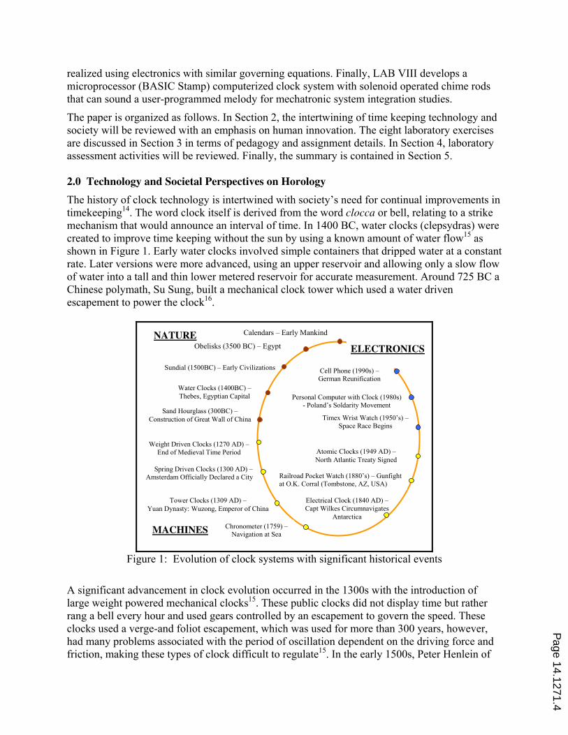
The history of clock technology is intertwined with society’s need for continual improvements in
timekeeping14
. The word clock itself is derived from the word clocca or bell, relating to a strike
mechanism that would announce an interval of time. In 1400 BC, water clocks (clepsydras) were
created to improve time keeping without the sun by using a known amount of water flow15
as
shown in Figure 1. Early water clocks involved simple containers that dripped water at a constant
rate. Later versions were more advanced, using an upper reservoir and allowing only a slow flow
of water into a tall and thin lower metered reservoir for accurate measurement. Around 725 BC a
Chinese polymath, Su Sung, built a mechanical clock tower which used a water driven
escapement to power the clock16
.
Water Clocks (1400BC) –
Thebes, Egyptian Capital
Sundial (1500BC) – Early Civilizations
Electrical Clock (1840 AD) –
Capt Wilkes Circumnavigates
Antarctica
Tower Clocks (1309 AD) –
Yuan Dynasty: Wuzong, Emperor of China
Spring Driven Clocks (1300 AD) –
Amsterdam Officially Declared a City
Weight Driven Clocks (1270 AD) –
End of Medieval Time Period
Sand Hourglass (300BC) –
Construction of Great Wall of China
Atomic Clocks (1949 AD) –
North Atlantic Treaty Signed
Obelisks (3500 BC) – Egypt
Calendars – Early Mankind
Railroad Pocket Watch (1880’s) – Gunfight
at O.K. Corral (Tombstone, AZ, USA)
Chronometer (1759) –
Navigation at Sea
Timex Wrist Watch (1950’s) –
Space Race Begins
Personal Computer with Clock (1980s)
- Poland’s Soldarity Movement
Cell Phone (1990s) –
German Reunification
NATURE
MACHINES
ELECTRONICS
Figure 1: Evolution of clock systems with significant historical events
A significant advancement in clock evolution occurred in the 1300s with the introduction of
large weight powered mechanical clocks15
. These public clocks did not display time but rather
rang a bell every hour and used gears controlled by an escapement to govern the speed. These
clocks used a verge-and foliot escapement, which was used for more than 300 years, however,
had many problems associated with the period of oscillation dependent on the driving force and
friction, making these types of clock difficult to regulate15
. In the early 1500s, Peter Henlein of
Page 14.1271.4
Nuremberg, Germany developed coiled springs that enabled clockmakers to shrink the size and
weight of the clocks. In 1656, Christian Huygens created the first pendulum clock. The addition
of a pendulum to regulate the escapement speed improved clock accuracy to within seconds a
day versus minutes in earlier types. Through the early 1800s, clocks had remained expensive due
to the limitations of custom manufacturing. However, Eli Terry created machines that could
mass produce identical clock components which lowered the cost of a clock and made it
affordable for more people to own17
. The introduction of electricity near the turn of the last
century allowed the replacement of mechanical drives with electric motors to move the clock
hands. This major technology leap occurred in 1929 when the vibration of a quartz crystal was
used for time measurement18
. When a small electric current is applied to quartz, the crystal
vibrates at a constant frequency which can be monitored. The last technological development of
clocks was the development of the atomic clock in the 1950s using cesium atoms. The cesium
atom’s natural frequency was accurate enough to be incorporated into the National Institute of
Standards and Technology’s official timekeeping system and recognized as the new international
unit of time in 1967, replacing the old second which was based on the Earth’s motion.
Much of modern life has come to depend on precise time (Cipolla, 1967). The day is long past
when society could function with a timepiece accurate to the nearest quarter-hour. For instance,
transportation, communication, financial transactions, manufacturing, electric power and many
other technologies have become dependent on accurate clocks18
. With this necessitated precision
timekeeping have come societal controversies with timekeeping. Several social debates are
highlighted below that can accompany the laboratory investigations.
Time Measurement Attitudes: As mechanical clocks became more numerous in Europe in the
fourteenth century, they brought about with them a change in attitude towards the measurement
of time14
. Villagers had been used to hearing bells toll to signify events from celebrations to call
to arms to pray time, but when the mechanical clock was added now people knew the hour as
well. Since public clocks were very expensive to build and maintain, the decision to build a clock
was of great debate for townspeople. Once the decision to build a clock was reached, the design
and size of the clock created further debate as towns rivaled others for having the right to claim
their town’s clock the best and the biggest clock.
Factory Work Hours: With the industrial revolution in America, a strict time schedule came for
factory workers. This is the first time the clock was used to signal the start and end of the
workday15
. To maximize work time, mangers of factories were known to tamper with the clocks
to get more work than agreed upon out of the workers. There were several instances throughout
New England and in New York City, where workers rose up against their employers to fight
against management corruption of time18
.
Sunday Work Protests: In early 1800 in America, a group of activists known as Sabbatarians
started a movement to protest Sunday work. As Sunday had always been held as a day of rest,
the Sabbatarians felt that commerce and industry were threatening God’s authority over time and
creating their own time. They protested against the United States Postal Service’s transportation
of mail on Sunday, the railroad industry running trains, and libraries/museums being open to the
public. They even protested against whalemen working on Sundays. This protest was the first in
America to demonstrate the efficiency of volunteer organizations for activism18
.
Standard Time: Before the railroad industry’s development of standard time, each community
on the railroad in the late 1800s was the driving force for the country to accept a uniform
Page 14.1271.5

standard time, so that the trains could operate on time and avoid collisions because of differences
in local times. The switch however, to a standard time did not come without opposition. People
living along boundary zones noticed that the sun and their clocks were widely different and did
not like living by an artificial time. Also, the railroad industry was one of the most powerful
industries of the time and many saw the standard time as an abuse of their power and corruption
of political officials to accept railroad time18
.
Daylight Saving Time: Daylight Saving Time (DST) was adopted in the United States during
WWI. As soon as the war ended, numerous protests, mostly from farmers, caused Congress to
repel the act. DST was again enacted during WWII. From 1945 to 1966, there was no federal law
regarding DST, so states and localities were free to choose whether or not to observe DST and
could choose when it began and ended. This understandably caused confusion, especially for the
broadcasting industry, as well as for railways, airlines, and bus companies. President Nixon
signed into law the Emergency Daylight Saving Time Energy Conservation Act of 1973,
returning the concept of daylight saving time on a national level. There has always been
opposition to daylight saving time, with some states or parts of states refusing to observe it.
Those working in the agricultural industry have always been the most vehement opposers of it
and there has always been debate as to whether or not it saves energy18
.
The history and controversies of time keeping can be integrated into the laboratory experiments.
Mumford1 stated that “… the clock was the most influential of machines, mechanically as well as
socially” which invites an accompanying societal perspective to the planned exercises. The
bench top experiments to be discussed in Section 3 can be integrated with the above societal
issues to encourage both technology exploration as well as social awareness of how time and
timekeeping has impacted our societal structure. As an example, students in the laboratory might
explore the vibrations and acoustics of chime rods in clocks and then be able to explore societal
aspects of the use of bells and gongs in public clocks during the Middle Ages and American
industrial revolution in an accompanying study/paper for a companion history or English course.
3.0 Time Keeping Experiments
A series of eight bench top experiments and simulation studies have been created based on a
horology (time keeping) theme. Although not exhaustive, these laboratory and analytical
investigations range from elementary to technically challenging to accommodate a wide student
audience. As shown in Table 1, the laboratory assignments have been summarized in tabular
format to highlight some of the pedagogical opportunities in terms of measurement techniques,
data acquisition, computer programming, modeling, design of experiments, and other. These
assignments can be modified as needed to emphasize different pedagogical aspects and selected
to offer comprehensive coverage of key learning criteria. The eight laboratory experiments will
now be briefly discussed to provide insight into the general background, learning objectives,
equipment, and class room procedures.
3.1 Operation and Gear Train Analysis of a Key Wound Mechanical Clock (Lab I)
A spring driven mechanical clock mechanism (springs removed for safety) will be
disassembled/assembled to analyze the time and strike gear trains, study the train ratio, and
measure the output torque and speed with comparison to calculated results.
Background: Clocks are used throughout the world to measure and keep track of time.
Mechanical clocks (refer to Figure 2) rely on four principles to make them functional. First,
Page 14.1271.6
every clock has to be powered and the most common ways for powering mechanical clocks are
coiled (key wound) springs and falling weights. Coiled springs have an advantage over weights
because they don’t require a lot of space and therefore, they make possible portable clocks and
watches. In most of these designs, the spring is wound up on one of the wheels in the clock that
is meshed with the rest, thus driving the whole mechanism. As the spring is unwound, it releases
power that is transmitted through the gears to the escapement. Second, an escapement
mechanism19
must be present in every clock design since its function is to create periodic
motions or equal intervals of power burst that are delivered to the gear train to keep time. Third,
the gear train consisting of set of gears controls and reduces the speed of rotations between the
power transferred to the clock and the output indicators. Finally, the last operating principle of
the clock deals with displaying the output of the clock’s function. The dial usually consists of 12
hours, 60 minutes, and 60 seconds that are equally spaced within 360° of rotation.
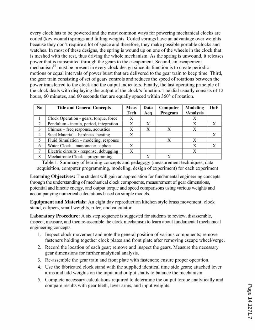
Table 1: Summary of learning concepts and pedagogy (measurement techniques, data
acquisition, computer programming, modeling, design of experiment) for each experiment
Learning Objectives: The student will gain an appreciation for fundamental engineering concepts
through the understanding of mechanical clock components, measurement of gear dimensions,
potential and kinetic energy, and output torque and speed comparisons using various weights and
accompanying numerical calculations based on simple models.
Equipment and Materials: An eight day reproduction kitchen style brass movement, clock
stand, calipers, small weights, ruler, and calculator.
Laboratory Procedure: A six step sequence is suggested for students to review, disassemble,
inspect, measure, and then re-assemble the clock mechanism to learn about fundamental mechanical
engineering concepts.
1. Inspect clock movement and note the general position of various components; remove
fasteners holding together clock plates and front plate after removing escape wheel/verge.
2. Record the location of each gear; remove and inspect the gears. Measure the necessary
gear dimensions for further analytical analysis.
3. Re-assemble the gear train and front plate with fasteners; ensure proper operation.
4. Use the fabricated clock stand with the supplied identical time side gears; attached lever
arms and add weights on the input and output shafts to balance the mechanism.
5. Complete necessary calculations required to determine the output torque analytically and
compare results with gear teeth, lever arms, and input weights.
No Title and General Concepts Meas
Tech
Data
Acq
Computer
Program
Modeling
/Analysis
DoE
1 Clock Operation - gears, torque, force X X
2 Pendulum - inertia, period, integration X X X X
3 Chimes – freq response, acoustics X X X X
4 Steel Material – hardness, heating X X
5 Fluid Simulation – modeling, response X X
6 Water Clock – manometer, siphon X X X
7 Electric circuits - response, debugging X X
8 Mechatronic Clock – programming X X
Page 14.1271.7
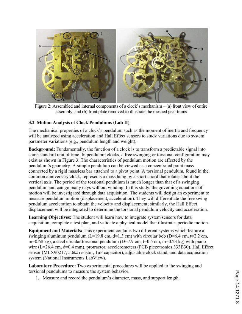
Figure 2: Assembled and internal components of a clock’s mechanism – (a) front view of entire
assembly, and (b) front plate removed to illustrate the meshed gear trains
3.2 Motion Analysis of Clock Pendulums (Lab II)
The mechanical properties of a clock’s pendulum such as the moment of inertia and frequency
will be analyzed using acceleration and Hall Effect sensors to study variations due to system
parameter variations (e.g., pendulum length and weight).
Background: Fundamentally, the function of a clock is to transform a predictable signal into
some standard unit of time. In pendulum clocks, a free swinging or torsional configuration may
exist as shown in Figure 3. The characteristics of pendulum motion are affected by the
pendulum’s geometry. A simple pendulum can be viewed as a concentrated point mass
connected by a rigid massless bar attached to a pivot point. A torsional pendulum, found in the
common anniversary clock, represents a mass hung by a short chord that rotates about the
vertical axis. The period of the torsional pendulum is much longer than that of a swinging
pendulum and can go many days without winding. In this study, the governing equations of
motion will be investigated through data acquisition. The students will design an experiment to
measure pendulum motion (displacement, acceleration). They will differentiate the free swing
pendulum acceleration to obtain the velocity and displacement; similarly, the Hall Effect
displacement will be integrated to determine the torsional pendulum velocity and acceleration.
Learning Objectives: The student will learn how to integrate system sensors for data
acquisition, complete a test plan, and validate a physical model that illustrates periodic motion.
Equipment and Materials: This experiment contains two different systems which feature a
swinging aluminum pendulum (L=19.8 cm, d=1.3 cm) with circular bob (D=6.4 cm, t=2.2 cm,
m=0.68 kg), a steel circular torsional pendulum (D=7.9 cm, t=0.5 cm, m=0.23 kg) with piano
wire (L=26.4 cm, d=0.4 mm), protractor, accelerometers (PCB piezotronics 333B30), Hall Effect
sensor (MLX90217, 5.6ȍ resistor, 1ȝF capacitor), adjustable clock stand, and data acquisition
system (National Instruments LabView).
Laboratory Procedure: Two experimental procedures will be applied to the swinging and
torsional pendulums to measure the system behavior.
1. Measure and record the pendulum’s diameter, mass, and support length.
Page 14.1271.8

2. Attach accelerometers and Hall Effect sensor to pendulums and calibrate using the
LabView data acquisition system.
3. Displace the pendulum (approximately 30º) and release so it swings/rotates freely.
Record several oscillations using data acquisition system.
4. Calculate the frequency of oscillation and moment of inertia from experimental data;
compare these values for each pendulum configuration.
5. Investigate the acceleration, velocity, and displacement for each pendulum. How do these
experimental results compare to the free swinging ideal (analytical) scenarios?
Figure 3: Experimental configuration of (a) torisonal and (b) swinging pendulum systems
3.3 Vibration Modes of a Chime Rod (Lab III)
The vibration and/or acoustic behavior of a chime rod, often struck by clocks to denote time
passage, will be investigated using a microphone and accelerometer with impact hammer to
determine the operating frequencies. For a greater challenge, a spiral gong with multiple modes
may be studied20
.
Background: Chime rods (refer to Figure 4) and spiral gongs are used inside mechanical clocks to
sound the passage of time. The striking hammer hits the chime rod or gong to produce vibrations as
driven by the time side of the clock interacting with the strike side. The impact of the striking hammer
against the rod generally produces a pleasing sound, which is dependent on the rod’s inner/outer
diameters and length. Chime rods offer a more precise musical note which can be used to sound a
melody. In this experiment, free vibration (when an object is impacted with an initial force and then
allowed to oscillate freely until the motion dampens out) will be investigated to determine the natural
frequency. The vibration behavior of various rods will be measured using an impact hammer with
accelerometers. To supplement this study, the rod’s acoustics will be recorded using a microphone
attached to a computer workstation. The recorded data will be analyzed with Fourier Transforms to
identify the operating frequencies; testing will be performed in a small semi-anechoic chamber.
Torsional
Pendulum
Swinging
Pendulum
Page 14.1271.9
Learning Objectives: The student will understand general acoustic and vibration principles,
relationship of sound vibration to musical notes, and Fast Fourier Transforms. They will learn
how to perform sound and vibration measurements, use data acquisition systems, and evaluate
simple acoustic and/or vibration relationships.
Equipment and Materials: Accelerometer (PCB 333B32), impact hammer (PCB 086C01),
microphone (Sony F-V130), microphone pre-amplifier (Midiman), chime rods (5), Matlab, and
SigLab (Spectral Dynamics 20-42) with Discrete Fourier Transform.
Laboratory Procedure: The Fast (Matlab) and Discrete (SigLab) Fourier Transform method in
Matlab allows spectrum analysis to be conducted on the recorded wave to determine the frequency.
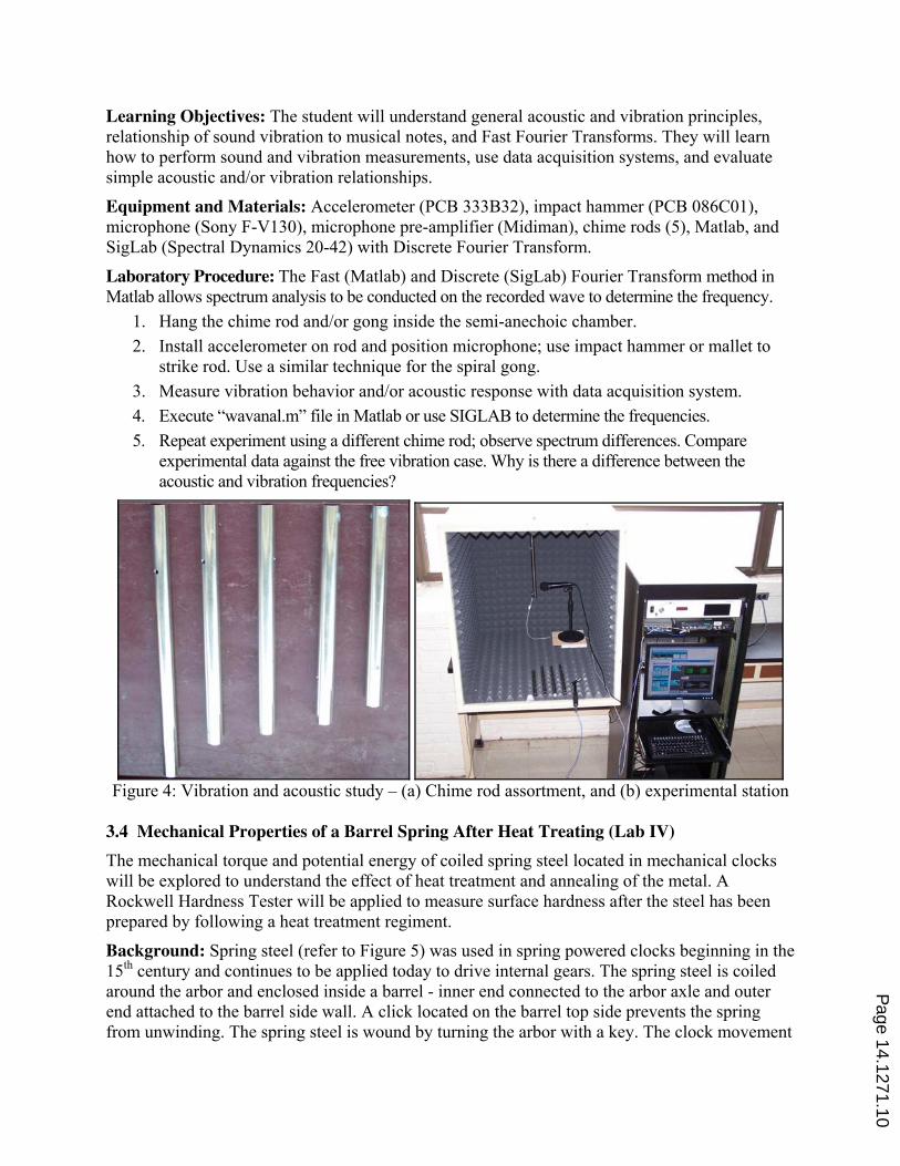
1. Hang the chime rod and/or gong inside the semi-anechoic chamber.
2. Install accelerometer on rod and position microphone; use impact hammer or mallet to
strike rod. Use a similar technique for the spiral gong.
3. Measure vibration behavior and/or acoustic response with data acquisition system.
4. Execute “wavanal.m” file in Matlab or use SIGLAB to determine the frequencies.
5. Repeat experiment using a different chime rod; observe spectrum differences. Compare
experimental data against the free vibration case. Why is there a difference between the
acoustic and vibration frequencies?
Figure 4: Vibration and acoustic study – (a) Chime rod assortment, and (b) experimental station
3.4 Mechanical Properties of a Barrel Spring After Heat Treating (Lab IV)
The mechanical torque and potential energy of coiled spring steel located in mechanical clocks
will be explored to understand the effect of heat treatment and annealing of the metal. A
Rockwell Hardness Tester will be applied to measure surface hardness after the steel has been
prepared by following a heat treatment regiment.
Background: Spring steel (refer to Figure 5) was used in spring powered clocks beginning in the
15th
century and continues to be applied today to drive internal gears. The spring steel is coiled
around the arbor and enclosed inside a barrel - inner end connected to the arbor axle and outer
end attached to the barrel side wall. A click located on the barrel top side prevents the spring
from unwinding. The spring steel is wound by turning the arbor with a key. The clock movement
Page 14.1271.10

is driven by external gears on the barrel’s top edge. In this laboratory, the mechanical torque and
stored potential energy of different specimens of spring steel due to heat treatments will be
explored. The students will design an experiment to study the spring stiffness using weights hung
from the apparatus for torque measurements. Further, the effects of heat treating and quenching
the spring steel may be tested using a Rockwell hardness tester. Heat Treating involves heating a
metal to high temperatures using an oven or a torch and then cooling by quenching in oil, water,
or air. Heat treating and quenching affects the mechanical properties (stiffness and hardness) of
the spring steel. The Rockwell tester measures the hardness of metal materials to evaluate the
effects of heat treating and quenching. The measurements are based on the net increase in depth
of the impression made by the indenter for minor and major loads applied to the test specimen.
Figure 5: Spring in clock barrel – (a) coil, (b) barrel with external teeth, and (c) side cut away
Learning Objectives: Students will learn how to heat treat and quench spring steel. The test
specimen’s mechanical properties will be measured through surface hardness and spring
elasticity. The student will explore the creation of test plans to complete the measurements.
Equipment and Materials: Spring steel (0.75”*0.0165”), propane gas torch, Rockwell hardness
tester (Rams 10AR), test fixture, weights, and oil/water baths.
Laboratory Procedure:
1. Measure the spring barrel torque on the test stand by applying external weights; calculate
the corresponding spring stiffness.
2. Determine initial hardness of spring steel test specimen using Rockwell hardness tester.
3. Heat the spring specimen using a torch (under supervision of technician) to a red color.
4. Quench steel in either an oil or water bath, or let air cool.
5. Repeat step 2 to determine how heat treating and quenching affect the hardness; a
different spring barrel with varying steel will then be supplied to measure the stiffness.
3.5 Cascading Water Tanks for Time Keeping Numerical Study (Lab V)
A series of elevated water tanks, with different sized outlets to regulate the drainage time, may
be mathematically modeled to analyze the subsequent time intervals. The governing equations
and system transient behavior will be analyzed using Matlab/Simulink. A turbine flow rate
sensor will be inserted to quantify the water outlet flow rate and calibrate the time period.
Background: Dating back to the 16th century BC, water clocks are one of the oldest types of time
keeping devices. Also known as clepsydra, these clocks were simple in design with only a storage
vessel, outlet sized to regulate the fluid flow, and columns with marked intervals. The tank fluid height
decreased (outflow device) at a constant rate. As the fluid level dropped, the lower portions of the
graduated columns were revealed with time denoted by equidistant markings. By 200 BC, an inflow
Page 14.1271.11

water clock, developed in China and eastern Asia, also featured a constant flow rate to measure time.
In this case, the inlet water supply provided a constant fluid stream into a storage tank outfitted with a
float device connected to a time indicator. Note that accurate time keeping was dependent on a
constant fluid flow rate. For this laboratory, a set of cascading water tanks will be analyzed to calibrate
the system for use in a time keeping application
Learning Objectives: Students will learn how to mathematically model fluid flow between
water tanks and evaluate different outlet geometries using computer based Matlab algorithms.
Equipment and Materials: Computer workstation with Matlab/Simulink software package.
Figure 6: Three cascaded water tanks with circulation pump for numerical fluid flow study
Procedure: The system consists of three identical water tanks (refer to Figure 6) with system
variables fluid inlet/outlet flows, and fluid height (pressure) as well as the system parameters of
tank diameter, and paddle wheel flow sensor. If the system is left to run as is, Tank 1 will empty
itself and all fluid in the system will eventually be lost. To maintain continual fluid system
operation, either an infinite water source or circulation pump can be considered so that tank 1
offers an uniform pressure, P1.
1. Derive the governing system (ordinary differential) equations for the cascading water
tanks with fluid height variables.
2. Determine numerical relationship between fluid height in Tank 3 and the exit flow rate.
3. Use Matlab/Simulink to numerically solve the governing equations to study transient
responses for the water tanks. What is the outlet flow rate of Tank 3 when the system has
reached steady-state?
4. Adjust the outlet geometry to create a flow rate to drive a paddle wheel flow sensor that
can be used for time keeping operations. What is the conversion of sensor output to time?
5. If desired, design a water pump system to circulate water from Tank 3 outlet to Tank 1
inlet to maintain continual fluid flow.
3.6 Operating Principles of the Gitton Water Clock (Lab VI)
The artistic water clocks created by Bernard Gitton can be analyzed to understand the application
of fluid flow principles for time keeping systems (ignore water pump). The basic concepts to be
examined include manometers, Bernoulli’s principle, and siphon effect in vessels.
Page 14.1271.12

Background: Water clocks have been designed by Bernard Gitton (refer to Figure 7a) that
demonstrate the use of fluid principles to track the passage of time as well as serve as art objects. Mr.
Gitton is a French scientist who has created multiple “time-flow clocks” located throughout the world.
One of the tallest clocks is located in Indianapolis at the Children’s Museum21 at 9.1 meters tall and 40
pieces of blown glass. The clock contains four subsystems - an oscillator (pendulum), a frequency
divider, a minute counter, and an hour counter. The pump that moves water from the bottom tank to
the top, and air bleed valves that remove unnecessary vacuums are not considered. The pendulum
features a small bowl at the top that accumulates water from an elevated reservoir. The bowl empties
into the first siphon as the pendulum swings (refer to Figure 7b) to provide power for clock functions.
The siphons in the clock are frequency dividers which convert the pendulum motion into a fluid
volume time display. A siphon moves liquid from one container to a lower elevation container via
gravity. As water is supplied by “dollops” (i.e., small fluid release) from the pendulum, the first dollop
fills the siphon half way22. The second dollop initiates a siphon effect that continues until the container
is drained. As the liquid moves through the cascaded siphons, it requires more time (increased period)
to fill the subsequent siphons due to increased volume. The last siphon does not operate at
atmospheric pressure. In addition, siphons may feature a connecting tube at a designated level to drain
away excess fluid to reduce overflow. When the liquid arrives at the bottom tank, a vacuum signal
triggers siphoning in the minute column. Similarly, a full minute column initiates a siphon effect of
the column to the bottom tank which triggers a vacuum signal that siphons the hour column. In this
laboratory, students will design an experiment to investigate fluid flow phenomenon through the use
of a manometer, reservoir, siphon tubes, and fluid mechanics concepts to understand the water clock.
Figure 7: Water clock – (a) structure with pendulum, frequency dividing siphons,
and time counter22
; and (b) pendulum with reservoir
Learning Objectives: The students will analyze water clock operation based on fluid mechanic
principles including manometers and siphons. The behavior of manometers and siphons will be
measured with bench top experiments that emphasize design of experiment, followed by the
mathematical modeling of the Gitton time flow clock.
Equipment and Materials: Manometer, siphon tubes, dual reservoirs, tape measure, and bucket.
Page 14.1271.13
Laboratory Procedure:
1. Analyze the operation of Bernard Gitton’s Children’s Museum of Indianapolis water
clock21
; identify the basic components utilized within the clock.
2. Review the theory of manometers and siphons; how do these relate devices relate to the
water clock’s basic design?
3. Design a manometer and siphon effect laboratory experiments to explore the water clock
concepts; perform the experiments and record pertinent information.
4. Apply Bernoulli’s principle to the clock’s analysis; can the height and diameter of the various
siphons be specified to achieve the required fluid flow behavior?
5. Integrate the pendulum’s motion into the clock’s fluid operation; what is the interface between
the mechanical and fluid domains? What is the impact of an external water pump?
3.7 Voltage Controlled Oscillator Electronic Circuit (Lab VII)
Using a breadboard, a voltage controlled oscillator (VCO) electrical circuit will be constructed to
generate an oscillatory output voltage signal. The transient behavior of the circuit should be
analogous to the mechanical motion of a swinging pendulum. The output signal’s frequency can
be designed through electronic component selection and measured with bench instrumentation.
Background: The advent of electronics permits the introduction of circuits to demonstrate some
operational behaviors similar to mechanical systems. Time keeping devices require an energy
source that provides accurate input characteristics (e.g., constant flow, pendulum swinging,
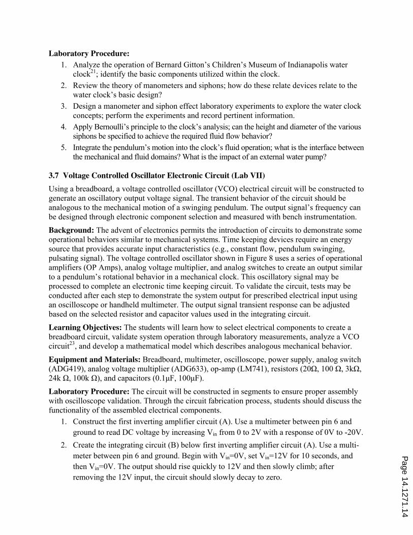
pulsating signal). The voltage controlled oscillator shown in Figure 8 uses a series of operational
amplifiers (OP Amps), analog voltage multiplier, and analog switches to create an output similar
to a pendulum’s rotational behavior in a mechanical clock. This oscillatory signal may be
processed to complete an electronic time keeping circuit. To validate the circuit, tests may be
conducted after each step to demonstrate the system output for prescribed electrical input using
an oscilloscope or handheld multimeter. The output signal transient response can be adjusted
based on the selected resistor and capacitor values used in the integrating circuit.
Learning Objectives: The students will learn how to select electrical components to create a
breadboard circuit, validate system operation through laboratory measurements, analyze a VCO
circuit23
, and develop a mathematical model which describes analogous mechanical behavior.
Equipment and Materials: Breadboard, multimeter, oscilloscope, power supply, analog switch
(ADG419), analog voltage multiplier (ADG633), op-amp (LM741), resistors (20ȍ, 100 ȍ, 3kȍ,
24k ȍ, 100k ȍ), and capacitors (0.1ȝF, 100ȝF).
Laboratory Procedure: The circuit will be constructed in segments to ensure proper assembly
with oscilloscope validation. Through the circuit fabrication process, students should discuss the
functionality of the assembled electrical components.
1. Construct the first inverting amplifier circuit (A). Use a multimeter between pin 6 and
ground to read DC voltage by increasing Vin from 0 to 2V with a response of 0V to -20V.
2. Create the integrating circuit (B) below first inverting amplifier circuit (A). Use a multi-
meter between pin 6 and ground. Begin with Vin=0V, set Vin=12V for 10 seconds, and
then Vin=0V. The output should rise quickly to 12V and then slowly climb; after
removing the 12V input, the circuit should slowly decay to zero.
Page 14.1271.14
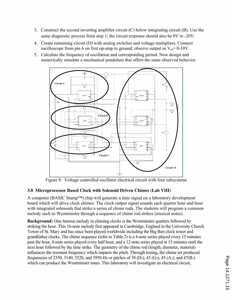
3. Construct the second inverting amplifier circuit (C) below integrating circuit (B). Use the
same diagnostic process from step 1; the circuit response should also be 0V to -20V.
4. Create remaining circuit (D) with analog switches and voltage multipliers. Connect
oscilloscope from pin 6 on first op-amp to ground; observe output as Vin= 0-10V.
5. Calculate the frequency of oscillation and corresponding period. Now design and
numerically simulate a mechanical pendulum that offers the same observed behavior.
Figure 8: Voltage controlled oscillator electrical circuit with four subsystems
3.8 Microprocessor Based Clock with Solenoid Driven Chimes (Lab VIII)
A computer (BASIC Stamp™) chip will generate a time signal on a laboratory development
board which will drive clock chimes. The clock output signal sounds each quarter hour and hour
with integrated solenoids that strike a series of chime rods. The students will program a common
melody such as Westminster through a sequence of chime rod strikes (musical notes).
Background: One famous melody in chiming clocks is the Westminster quarters followed by
striking the hour. This 16-note melody first appeared in Cambridge, England in the University Church
Tower of St. Mary and has since been played worldwide including the Big Ben clock tower and
grandfather clocks. The chime sequence (refer to Table 2) is a 4-note series played every 15 minutes
past the hour, 8-note series played every half hour, and a 12-note series played at 15 minutes until the
next hour followed by the time strike. The geometry of the chime rod (length, diameter, material)
influences the resonant frequency which impacts the pitch. Through testing, the chime set produced
frequencies of 2350, 3140, 3520, and 3950 Hz or pitches of 38 (D7), 43 (G7), 45 (A7), and 47(B7)
which can produce the Westminster tones. This laboratory will investigate an electrical circuit,
Circuit A
Circuit B
Circuit C
Circuit D
Page 14.1271.15

solenoid actuators, and computer programmed code to drive a set of mechanical chimes with a
microprocessor (BASIC Stamp Board as shown in Figure 9a) based digital clock.
Time Musical Note Sequence
00:15 B, A, G, D
00:30 G, B, A, D G, A, B, G
00:45 B, G, A, D D, A, B, G B, A, G, D
00:00 G, B, A, D G, A, B, G B, G, A, D D, A, B, G
Table 2: Westminster melody note sequence for quarter hour chimes using four notes
Learning Objectives: The student will learn how to integrate electro-mechanical components
(actuators, electrical devices, microprocessor) to create a functional flexible mechatronic clock
and develop accompanying computer algorithms. Further, the student will be able to collect
operating data through computer based instrumentation to evaluate system functionality.
Equipment and Materials: BASIC Stamp™ chip, breadboard, Deltrol C6 solenoids, chime rod,
host computer for program development, and oscilloscope.
Laboratory Procedure: The programming language set for the BASIC Stamp chip is similar to
Matlab and/or C++. The teams will utilize a Parallax StampWorks development board (refer to
Figure 9a) that hosts digital clock functions and drives external solenoids to strike the rods.
1. Establish host workstation computer to BASIC Stamp communication; review input and
output functions for the clock and microprocessor chips.
2. Create a digital clock with the microprocessor real time clock circuit (use example program).
3. Demonstrate the software algorithm and clock functionality.
4. Connect the solenoids (refer to Figure 9b) to amplifier outputs 1-4 and common power; route
wires from controller output ports 8-11 to amplifier input ports 1-4.
5. Develop algorithm drivers to operate the four solenoids in proper sequence based on time
interval with controller output ports 8-11.
6. Demonstrate the complete system operation for time keeping and solenoid chiming.
Figure 9: Mechatronic clock - (a) Development board with Stamp chip, and (b) solenoid chimes
4.0 Laboratory Assessment
To evaluate each laboratory experiment, an assessment tool will be administered at the
conclusion of the given exercise to gather student feedback. The assessment document (refer to
Appendix) has been divided into four areas. The first three segments seek information regarding
the performance of the laboratory teaching assistants (Questions 1-2), student work load and
Clock Chip Display Controller
Page 14.1271.16
difficulty for the laboratory (Questions 3-4), and whether the assignment reinforced engineering
concepts and student skills (writing, software, statistics, design and conducting experiments) per
Questions 5-10. The responses are entered on a strongly disagree (SD), disagree (D), neutral (N),
agree (A), and strong agree (SA) scale which can be readily translated into numerical scores. For
the fourth segment (Questions 11-13), the students can offer written comments regarding
positive and negative aspects of the experiment, and other suggestions pertaining to the overall
laboratory experience. It should be noted that this assessment form is actively applied in the
undergraduate laboratory courses in the Department of Mechanical Engineering at Clemson
University after each experiment. The collected feedback will be reviewed and combined with
observations from the teaching assistants and faculty to modify the experiments as appropriate to
yield an improved learning experience.
5.0 Summary
The engineering education laboratory provides students an environment to explore classical and
innovative experiments that reinforce fundamental concepts and classroom theory. In many
instances, the laboratory experience can be viewed as a distinguishing feature of the engineering
education process. In this paper, a series of eight horology inspired experiments have been
presented with accompanying background, learning objectives, equipment and materials, and test
procedure. To complement the engineering investigations, an accompanying set of societal issues
may be identified that allow students to examine the impact of time measurement on mankind.
The availability of a set of experimental and numerical laboratory assignments with a unifying
theme may fulfill the need for comprehensive and challenging student exercises.
Acknowledgements
The authors wish to acknowledge the contributions of J. Dixon, M. Goldbach, J. Hodges, A.
Makarchyk, D. Norfleet, J. Savitsky, S. Schnedier, L. Stutkowski, and A.Wilburn.
References
1. Mumford, L., “Technics and Civilization”, Routledge & Kegan Paul: London, (p. 14, 134), 1934.
2. Knight, C., and McDonald, G., “Attributes of a Modern Mechanical Engineering Laboratory”, proceedings of
the ASEE Annual Conference, pp. 933-941, Portland, OR, June 2005.
3. Layton, R. A., Mech, A., and Mayhew, J., “Ideas Into Action: Using Learning Objectives to Revitalize a
Mechanical Engineering Laboratory Sequence”, proceedings of the ASME IMECE Congress, pp. 239-244,
Anaheim, CA, November 2004.
4. Yoder, J. D., Hurtig, J., and Rider, M., “Providing Hands-on Experiences in a Mechanical Engineering Controls
Systems Course”, proceedings of ASEE Annual Conference, pp. 11653-11662, Salt Lake City, UT, June 2004.
5. Lu, F. K., Panicker, P. K., and Webb, M. B., “Introducing Modern Laboratory Experiences to Mechanical and
Aerospace Engineering Students”, proceedings of ASME IMECE Congress, vol. 7, pp. 443-452, Seattle, WA,
November 2007.
6. Chastain, J., Smith, H., Morehead, M., Moline, D., and Wagner, J. “Senior Mechanical Engineering Laboratory
at Clemson university - Experiments, Learning Objectives, and Assessment”, proceedings of ASEE Annual
Conference, 2006-1012, Chicago, IL, June 2006.
7. Bernstein, D. S., “Feedback Control: An Invisible Thread in the History of Technology”, IEEE Control systems
Magazine, vol. 22, no. 2, pp. 53-68, April 2002.
Page 14.1271.17
8. Wagner, J., Huey, C., and Knaub, K., “Clock Mechanism Fundamentals for Education – Modeling and
Analysis”, proceedings of the ASME Dynamic Systems and Controls Conference , DSCC2008, Ann Arbor, MI,
October 2008.
9. Burchett, B. , Fisher, D., and Cornwell, P., “Advances in Hands-on Experiments and Simulations for an
Introductory Dynamics Course”, proceedings 37th ASEE/IEEE Frontiers in Education Conference, pp. T3G18-
T3G23, Milwaukee, WI, October 2007.
10. Delson, N., “Creating a Positive Introductory Design Experience”, proceedings of Education that Works:
NCIAA 8th Annual Meeting, pp. 59-65, San Jose, CA, March 2004.
11. MAE3, www.maelabs.ucsd.edu/mae3, September 2008.
12. NSRC - National Science Resource Center, “Measuring Time”, Science and Technology for Children,
Smithsonian Institution and National Academy of Sciences, 2002.
13. Kolberg, E., Reich, Y., and Levin, I., “Project Based High School Mechatronics Course”, International Journal
of Engineering Education, vol. 19, no. 4, pp. 557-562, 2003.
14. Cipolla, C. M., “Clocks and Culture 1300-1700”, Collins: London, 1967.
15. Landes, D. S., “Revolution in Time”, Harvard University Press: Cambridge, 1983.
16. Burstall, A. F., Landsdale, W. E., and Elliott, P., “A Working Model of the Mechanical Escapement in Sun
Sung’s Astronomical Clock Tower”, Nature, vol. 199, no. 4900, pp. 1242-1244, September 28, 1963.
17. Hindle, B., and Lubar, S., “Engines of Change: The American Industrial Revolution 1790-1860”, Smithsonian
Institution Press: Washington, D.C, 1986.
18. Stephens, C. E., “On Time: How America Has Learned to Live by the Clock”, Bulfinch Press Book: New York,
2002.
19. Lepschy, A. M., Milan, G. A., and Viaro, U., “Feedback Control in Ancient Water and Mechanical Clocks”,
IEEE Transactions on Education, vol. 35, no. 1, pp. 3-10, February 1992.
20. Perrin, R., Charnley, T., Swallowe, G. M., and Banu, H., “Modes Of The Spiral Clock Gong”, Journal of Sound
and Vibration, vol. 162, no. 1, pp. 1-12, March 1993.
21. Water Clock, Children’s Museum of Indianapolis, www.childrensmuseum.org/themuseum/icons/
waterclock.htm, 2008.
22. Gitton, www.marcdatabase.com/~lemur/dm-gitton.html, 2008.
23. Baker, G. L., and Blackburn, J. A., “The Pendulum”, Oxford University Press: New York, 2005.
Page 14.1271.18
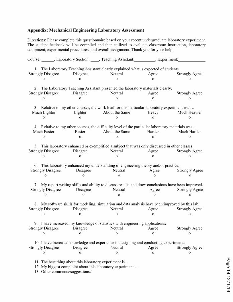
Appendix: Mechanical Engineering Laboratory Assessment
Directions: Please complete this questionnaire based on your recent undergraduate laboratory experiment.
The student feedback will be compiled and then utilized to evaluate classroom instruction, laboratory
equipment, experimental procedures, and overall assignment. Thank you for your help.
Course: ______, Laboratory Section: ____, Teaching Assistant:__________, Experiment:_____________
1. The Laboratory Teaching Assistant clearly explained what is expected of students.
Strongly Disagree
o
Disagree
o
Neutral
o
Agree
o
Strongly Agree
o
2. The Laboratory Teaching Assistant presented the laboratory materials clearly.
Strongly Disagree
o
Disagree
o
Neutral
o
Agree
o
Strongly Agree
o
3. Relative to my other courses, the work load for this particular laboratory experiment was…
Much Lighter
o
Lighter
o
About the Same
o
Heavy
o
Much Heavier
o
4. Relative to my other courses, the difficulty level of the particular laboratory materials was…
Much Easier
o
Easier
o
About the Same
o
Harder
o
Much Harder
o
5. This laboratory enhanced or exemplified a subject that was only discussed in other classes.
Strongly Disagree
o
Disagree
o
Neutral
o
Agree
o
Strongly Agree
o
6. This laboratory enhanced my understanding of engineering theory and/or practice.
Strongly Disagree
o
Disagree
o
Neutral
o
Agree
o
Strongly Agree
o
7. My report writing skills and ability to discuss results and draw conclusions have been improved.
Strongly Disagree
o
Disagree
o
Neutral
o
Agree
o
Strongly Agree
o
8. My software skills for modeling, simulation and data analysis have been improved by this lab.
Strongly Disagree
o
Disagree
o
Neutral
o
Agree
o
Strongly Agree
o
9. I have increased my knowledge of statistics with engineering applications.
Strongly Disagree
o
Disagree
o
Neutral
o
Agree
o
Strongly Agree
o
10. I have increased knowledge and experience in designing and conducting experiments.
Strongly Disagree
o
Disagree
o
Neutral
o
Agree
o
Strongly Agree
o
11. The best thing about this laboratory experiment is…
12. My biggest complaint about this laboratory experiment …
13. Other comments/suggestions?
Page 14.1271.19