time-dependent viscous deformation of a drop in a …stonelab/publications/pdfs/from...
TRANSCRIPT
J. Fluid Mech. (1996), 001. 317, p p . 215-299 Copyright 0 1996 Cambridge University Press
275
Time-dependent viscous deformation of a drop in a rapidly rotating denser fluid
By J. R. LISTER' AND H. A. STONE2 'Department of Applied Mathematics and Theoretical Physics, University of Cambridge,
Cambridge CB3 9EW, UK *Division of Applied Sciences, Harvard University, Cambridge, MA 021 38, USA
(Received 29 November 1995 and in revised form 9 February 1996)
Viscous stretching of a cigar-shaped drop due to the centrifugal pressure field in a surrounding rapidly rotating denser fluid is analysed. Scaling arguments are used to examine the various contributions to the viscous stresses resisting deformation, and a number of asymptotic regimes are identified which are delineated by the relative magnitudes of the aspect ratio, the viscosity ratio and unity. These asymptotic regimes may usefully be described as the bubble, pipe, sliding-rod and toffee-strand limits. Detailed analysis based upon a slenderness assumption combined with an integral representation of Stokes equations is used to derive evolution equations for the shape of the drop as a function of time in the different regimes. In the limit that interfacial- tension effects are negligible, similarity solutions are developed in which the length of the drop is found to increase as t 2 / 5 , t'I4, ( t In t) ' /4 and t. The analytical results are in good agreement with numerical simulations based upon a boundary-integral solution to the full viscous flow equations.
1. Introduction When a spherical drop of one fluid is placed on the axis of a rotating immiscible
fluid of greater density the drop is deformed, indeed it is 'squeezed', by the centrifugal pressure field of the surrounding dense fluid. The drop thus extends along the direction of the rotation axis. A steady equilibrium state of rigid rotation is eventually established in which the centrifugal stresses driving deformation are exactly balanced by the stresses due to interfacial tension which resist further deformation. The equilibrium shape is thus prolate (cigar-shaped), and if surface tension is weak compared with centrifugal pressure in the dimensionless sense defined below, then the shape will be long and slender. In this paper we use lubrication theory and boundary-integral calculations to study the transient distortion of a drop toward this slender shape. Scaling laws for the stretching and thinning rates and similarity solutions for the drop shape are developed for a range of viscosity ratios of the inner to outer fluids, and a number of distinct asymptotic regimes are identified.
The basic phenomenon of interfacial distortion due to the centrifugal pressure in a rotating fluid is utilized in spinning-drop tensiometers to determine the interfacial tension between two liquids from the final equilibrium drop shape (Vonnegut 1942). If the fluids are very viscous then some extrapolation of the slow transient distortion may be necessary to determine the equilibrium shape (Elmendorp & De Vos 1986). More recently, the spinning-drop tensiometer has been used to study the rheological

276 J. R. Lister and H . A. Stone
properties of liquids by examining the transient distortion of a slender drop under the assumption that the dynamical response is similar to that of a drop placed in a viscous extensional flow (Hsu & Flumerfelt 1975; Joseph et al. 1992). The initial transient deformation of a nearly spherical drop in the viscous flow generated by the actual centrifugal pressure field has also been described recently (Stone & Bush 1996). Direct numerical simulation of the full Navier-Stokes equations using a finite- element method has incorporated the geometry of a typical spinning-drop device (Hu & Joseph 1994).
The previous analytical investigations either evaded the difficulties of describing the actual centrifugal forcing or assumed the approximate form of the external flow or drop shape. In this paper we study the time-dependent stretching process. The important dynamical balance is between the centrifugal driving force and viscous forces acting inside and outside the drop. The lubrication approximation is first used to study the case of highly distorted slender drops that are still far from the equilibrium shape eventually established by surface tension. Similarity solutions are developed, and the radius and length of the drop are shown to evolve according to simple power laws whose detailed form depends on the viscosity ratio between the two fluids and the aspect ratio of the drop. The lubrication analysis is also used to study drop deformation in a cylindrical sleeve typical of the container of a spinning-drop tensiometer. The case of very viscous drops is treated separately using the viscous-thread equations. A numerical solution based on the boundary-integral method and incorporating the effects of interfacial tension is then used to study the transient distortion of a drop in an unbounded fluid and the results show excellent agreement with the lubrication analysis for the cases in which interfacial tension is weak.
A common application of the lubrication approximation to free-boundary problems has been to the study of spreading gravity currents where the driving force is the difference in hydrostatic pressure between the current and the surrounding fluid (e.g. Huppert 1982; Lister & Kerr 1989). In such cases an initially hemispherical or spherical drop spreads over a surface or at a fluid-fluid interface into an oblate (pancake-like) shape, which is geometrically unlike the centrifugally driven prolate shapes of interest here. Nevertheless, to analyse completely either buoyancy-driven or centrifugally driven spreading, it is necessary to study viscous effects internal and external to the spreading drop. (Similar considerations apply to a drop in a straining flow. e.g. Taylor 1964.) A recent study of buoyancy-driven spreading of a drop beneath a planar free surface (Koch & Koch 1995) also used a combination of boundary-integral and lubrication analyses to study large deformation of flattened drops as a function of the viscosity ratio and aspect ratio. Our work has mathematical similarities with the study by Koch & Koch and the spun drops might be thought of as cylindrical gravity currents in a radial, rather than unidirectional, gravity field.
2. Problem statement Consider the deformation of an initially spherical drop in a rapidly rotating viscous
fluid. Let the drop have density p - Ap and viscosity Ap and the suspending fluid have density p and viscosity p (figure 1). Assume that Ap > 0 so that upon rotation the drop is aligned with, and extended along, the rotation axis and let the undeformed radius of the drop be R so that its volume is V = $R3. The interfacial tension, denoted by y , is assumed to be constant.
Cylindrical coordinates ( r , 0, z) are used, where the z-axis is defined by the angular
Deformation of a drop in a rapidly rotating denserjluid 277
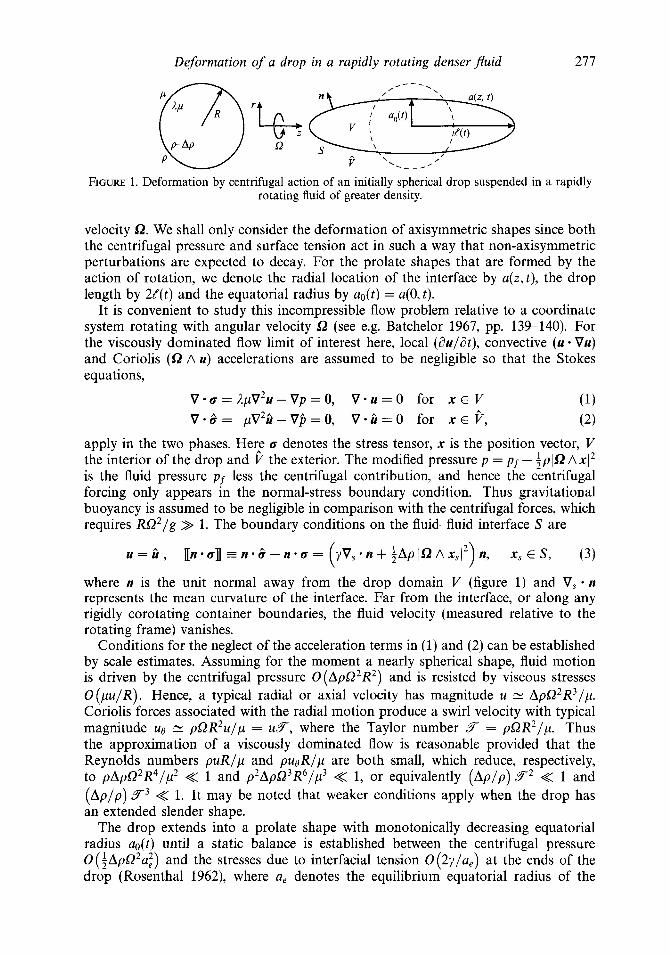
FIGURE 1. Deformation by centrifugal action of an initially spherical drop suspended in a rapidly rotating fluid of greater density.
velocity SL. We shall only consider the deformation of axisymmetric shapes since both the centrifugal pressure and surface tension act in such a way that non-axisymmetric perturbations are expected to decay. For the prolate shapes that are formed by the action of rotation, we denote the radial location of the interface by a(z,t), the drop length by 2/(t) and the equatorial radius by ao(t) = a(0, t).
It is convenient to study this incompressible flow problem relative to a coordinate system rotating with angular velocity f2 (see e.g. Batchelor 1967, pp. 139-140). For the viscously dominated flow limit of interest here, local (duldt), convective (u * Vu) and Coriolis (f2 A u) accelerations are assumed to be negligible so that the Stokes equations,
v . ~ = A ~ v ~ u - v ~ = o , V . U = O for X E v (1) v.&= p ~ ~ i i - v j j = o , v. i i=o for X E P , (2)
apply in the two phases. Her: a denotes the stress tensor, x is the position vector, V the interior of the drop and V the exterior. The modified pressure p = pf - i p l f 2 AxI2 is the fluid pressure pf less the centrifugal contribution, and hence the centrifugal forcing only appears in the normal-stress boundary condition. Thus gravitational buoyancy is assumed to be negligible in comparison with the centrifugal forces, which requires R Q 2 / g >> 1. The boundary conditions on the fluid-fluid interface S are
u = i i , 1n.an = n . & - n . a = y v , - n + j ~ p 1 n ~ X , 1 ~ ) n , X , E S , (3) ( where n is the unit normal away from the drop domain V (figure 1) and V, - n represents the mean curvature of the interface. Far from the interface, or along any rigidly corotating container boundaries, the fluid velocity (measured relative to the rotating frame) vanishes.
Conditions for the neglect of the acceleration terms in (1) and (2) can be established by scale estimates. Assuming for the moment a nearly spherical shape, fluid motion is driven by the centrifugal pressure O ( A p 0 2 R 2 ) and is resisted by viscous stresses O ( p u / R ) . Hence, a typical radial or axial velocity has magnitude u N ApQ2R3/p . Coriolis forces associated with the radial motion produce a swirl velocity with typical magnitude uo 1: pQR2u/p = u F , where the Taylor number 5 = p Q R 2 / p . Thus the approximation of a viscously dominated flow is reasonable provided that the Reynolds numbers p u R / p and pu&p are both small, which reduce, respectively, to p A p 0 2 R 4 / y 2 << 1 and p2ApQ3R6/p3 << 1, or equivalently ( A p l p ) F2 << 1 and ( A p l p ) F3 << 1. It may be noted that weaker conditions apply when the drop has an extended slender shape.
The drop extends into a prolate shape with monotonically decreasing equatorial radius ao(t) until a static balance is established between the centrifugal pressure O ( ~ A p Q 2 a ~ ) and the stresses due to interfacial tension 0(2y/a,) at the ends of the drop (Rosenthal 1962), where a, denotes the equilibrium equatorial radius of the
278 J. R. Lister and H . A. Stone
extended drop. The static shapes may be described by the rotational Bond number
Ap!L2R3
Y B = (4)
Indeed, for the highly distorted slender shapes expected at large Bond numbers, the above simple order-of-magnitude estimates for the stresses, along with volume conservation ( 4nR3 = 0(2na3te)), predict an equilibrium radius a, and half-length t, given by
e, (23??)2/3 -N-
at? R R - 6 ’ - 2i (4/B)li3,
These results are actually in perfect agreement with detailed calculations (Rosenthal 1962) since the equilibrium shape for B >> 1 is almost a cylinder with spherical endcaps of radius a,. Equation ( 5 ) shows that neglect of surface tension in an analysis of the global extension of a drop is valid if B >> t /ao . Surface tension will have a local influence at the end of the drop if the radius of curvature there, which need not be O(ao), falls to a value comparable to / /B .
We are primarily concerned in this paper with transient deformation towards the highly distorted shapes characteristic of B >> 1. Scaling arguments for the time- dependent stretching rates when the dominant resistance is viscous and B >> / /a0 >> 1 are described in $3 and detailed solutions are derived in $94-6. Small-deformation theory for the time-dependent shapes characteristic of the less interesting limit B << 1 is described by Stone & Bush (1996). In general, the intermediate situation in which B = O( 1) and the situation in which / /a0 = O ( B ) both require numerical solutions, examples of which are provided in $7.
3. Scaling analyses for slender shapes We consider two configurations: an unbounded geometry and a drop centred in a cylindrical container. The drop is assumed to be long and slender with equatorial radius a. much less than the half-length 8. Estimates for the rates of elongation and thinning are established by seeking a balance between the centrifugal pressure ~ A p a ’ u ~ multiplied by the area O(7cai) over which it acts and the largest resisting viscous stress multiplied by the area over which it acts. The largest viscous stress is found to depend on both the viscosity ratio I I and the aspect ratio //ao. For clarity and simplicity we will retain multiplicative constants, such as 27c and :7c, in areas and volumes in the text but drop them in the displayed equations for t ( t ) etc. (If they are retained throughout then the scaling estimates of the multiplicative coefficients in e(t) are found to be in reasonable agreement with the actual values obtained from the detailed analyses presented later.) We first consider the unbounded configurations in 993.1-3.3 and briefly describe the bounded case in 93.4. The transition times between the different dynamical limits are summarized in 93.5.
3.1. Low viscosity ratios: I I << ao/e << 1 For sufficiently low viscosity ratios 1, rearrangement of the internal fluid as the drop extends generates less viscous dissipation than deformation of the external fluid. Hence, owing to the distribution of centrifugal pressure, we expect the shape of a low-viscosity-ratio, nearly inviscid, drop to be that of a circular near-cylinder with domed endcaps. The primary resistance to deformation is associated with pushing fluid out of the way of the advancing endcaps of the drop as it extends.

Deformation of a drop in a rapidly rotating denserjuid 279
A force balance in the neighbourhood of the nose, which has radius O(ao), surface area O(27cai) and moves at velocity U = d//dt, is 27cai.pU/ao 1: iApQ2ai.7cai. Using the volume constraint in the approximate form 27caiG 1: V and estimating U 1: G/t yields the time-dependent length and radius of the drop
An estimate of the neglected viscous dissipation inside the drop and along the cylindrical boundary of the drop shows that the estimates (6) are appropriate when I I << ao/t << 1. We thus note that, for a given small viscosity ratio il > 0, the shape evolves according to (6) for early times but eventually ao/G < 1 and it is necessary to account for the viscous shear stresses along the length of the drop, as we now describe.
3.2. Intermediate viscosity ratios: ao// << il << (//ao)' /In ( / /ao)
For more viscous inclusions, the shear stresses generated by movement of the internal fluid along the axis towards the ends of the drop are important and a pressure gradient iApQ2ai / / is established along the (half) length of the drop. The internal shear occurs on a lengthscale O(ao), whereas analysis of the axial motion of a slender body with radius a0 and length G shows that the external shear occurs on the somewhat larger scale O(a0 ln(//ao)) (see, for example, Batchelor 1970, Cox 1970 or the logarithms that arise in other biharmonic and Laplacian problems in a nearly cylindrical geometries). Which of these shears gives the dominant contribution to U , if either, depends on the relative magnitudes of il and 1/ ln(t/ao).
For the case I I << l/ln(G/ao) the internal shear is dominant, the effective viscous shear stress is O(ilpU/ao), the total viscous resistance along the length of the drop is 0(27cao/. IIpU/ao) and thus the rates of extension and thinning are
For the converse case ,I >> l/ln(//ao), similar estimates may be used to argue that
where ? = p/ApQ2V2I3 and the factors ln(t/?) arise from a leading-order estimate of ln(G/ao), which is assumed to be much greater than 1.
Estimates for the magnitude of the neglected dissipation show that (7) or (8) is a valid approximation provided ao/G << I I << ( G / u o ) ~ /In (G/ao), which spans a large range of viscosity ratios for highly extended drops. The factor In ( t / uo ) may not be very large, even for an extended drop, and, for simplicity, we will sometimes omit it when writing bounds on I I though we will retain it when keeping track of detailed error estimates in the lubrication analyses.
3.3. High viscosity ratios: 1 >> ( ~ / a o ) ~ / ln ( t /uo> >> 1 Sufficiently viscous extended drops resist deformation under the centrifugal pressure primarily owing to internal axial velocity gradients. The deformation is analogous to the stretching of a piece of toffee. In this case a balance of the centrifugal pressure against an extensional viscous stress based on a strain rate U/G gives
280
~ A p Q 2 a ~ 2: 3ApU/L, which leads to stretching and thinning according to
J. R. Lister and H . A. Stone
The neglect of the external viscous shear stresses, which act over the surface area of the drop, in comparison to the internal extensional stresses, which act over the cross-section, (27caof. pU/ao << nut . 1pU/L'), limits these estimates of the evolution of the drop to A >> ( I P / U ~ ) ~ . Hence, as in 33.1, the stretching and thinning estimates of slender shapes given by (9) are limited to 'early' times, and they eventually become inapplicable when large aspect ratios ( P / u o ) ~ >> A are attained, after which the shape changes according to (8).
3.4. Elongation in a corotating rigid cylinder Equations (6)-(9) require little modification for drops spreading along the axis of a rotating fluid-filled cylinder of radius A provided that the cylinder walls are not so close to the drop as to significantly change the scaling estimate of the viscous resistance. A sufficient condition is A >> ao, though this can be relaxed a little for the cases of high and low viscosity ratios at the expense of imposing tighter conditions on A. For the case of intermediate viscosity ratios, the only modification to the stress balance, and hence to (8), is that the external gradients occur on the lengthscale O(ao ln(A/ao)), which is the appropriate scale for velocity variations as obtained, for example, in the textbook problem of a circular rod sliding axially along the centreline of a fluid-filled cylinder (e.g. Happel & Brenner 1983, p. 341).
3.5. Transition times In the preceding sections we derived scaling estimates for the dimensions of a spun drop, which are appropriate in various asymptotic regimes defined by the relative magnitudes of 1, / / ao , Al l2 , A-l, ellA and a. Since [ / a o is an increasing function of time, a drop will typically pass through several of these asymptotic regimes as it extends (figure 2). In all cases when [ /a0 NN 1 the shape can be described by small-deformation theory (Stone & Bush 1996). If A9 >> 1 the drop extends until [/a0 = O(L8). The detailed time-dependent response during large deformation depends on the magnitude of A.
If A << 1 there is an intermediate regime in which A-' >> [ / ao >> 1, resistance is dominated by normal stresses in the external fluid on the ends of the drop and axial extension proceeds according to (6). If 1 >> 1 there is an alternative intermediate regime in which 1 >> ( t / a ~ ) ~ >> 1, resistance is dominated by extensional stresses in the drop and extension proceeds according to (9). In each case, provided that 28 >> I-' or All2, as appropriate, the flow makes a transition to a regime in which 28 >> [ / a o >> Ap1 ,1 l l2 , resistance is dominated by shear stresses along the length of the drop and extension proceeds according to (7) or (8). The transition from (6) to (7) occurs when [/a0 = O ( t ' ) or
Similarly,
t -
the transition from (9) to (8) occurs when ( t /u~)~/ ln(e/ao) = O(1) or

Near-sphere B e 1 e/u0-1e 1
If 1-' >> 99 >> 1 or All2 >> &? >> 1 the equilibrium (5) is attained before the relevant transition to (7) or (8) is attained. Alternatively, if neither 1-1 >> 1 nor 11/2 >> 1 then there is no intermediate regime and extension proceeds according to (7) or (8) while 99 >> [/a0 >> 1, until equilibrium is attained after a time
Equilibrium +B124
a,, 1-B/12 -N-
4. Lubrication analyses - intermediate viscosity ratios In this section the lubrication approximation is used to study the evolution of a slender extending drop in the regime of intermediate viscosity ratios ao/8 << A << (8/ao)2/ ln(t/ao). The effects of interfacial tension are neglected. Because of the approximations made in these analyses, the detailed predictions are expected to be inaccurate in the immediate neighbourhood of the nose of the drop. Experience from previous problems (Huppert 1982; Lister & Kerr 1989; Koch & Koch 1995) suggests that the local error at the nose of the flow has a negligible effect on the global dynamics and on the solution away from the nose.
We wish to construct approximate solutions to (1)-(3) for the cases of a drop in an unbounded geometry and of a drop in a rotating rigid cylindrical container. The latter configuration is more straightforward as standard lubrication ideas may be applied directly.
It is convenient in the detailed analysis to scale all lengths by the undeformed drop radius R, velocities by the representative value Apfi2R3/p, time by the convective scale p/ApQ2R2 and pressures by ApQ2R2. To maintain a simple notation, we will denote all variables, now dimensionless, by the same symbols as in &1-3.
4.1. Drop deformation in an unbounded ju id Consider the transient fluid motion that is generated when a slender drop with ao(t) << [ ( t ) extends, owing to centrifugal stresses, along the axis of an unbounded

282 J. R. Lister and H. A. Stone
rotating fluid. In general, away from the ends of the drop axial derivatives scale as /-’ and radial derivatives as a;’. Also, the radial velocities are much smaller than the axial velocities since u, = O(u,ao/t).
The external fluid responds as a boundary-driven flow so that the external dynamic pressure gradient is small for positions away from the ends of the drop. It follows from the normal stress balance at the interface that the internal pressure is centrifugally dominated and hence that the internal flow is driven by the axial pressure gradient
where the (dimensionless function) a(z, t ) describes the shape of the drop. Thus, from the z-component of the equation of motion (l), the internal flow is given by
uZ(r ,z , t ) = U(z , t ) + where U(z , t ) is the centreline velocity in the drop. Integration of the continuity equation for the internal flow and use of (14) leads to the evolution equation
aa2 a 1 a2a6 at a Z 4 8 ~ a z 2 - + - (Ua’) + -- = o
for the cross-sectional area of the drop u2(z, t). While local lubrication analysis of the internal flow is sufficient to derive the parabolic profile in (14) of relative motion within the drop, the absolute motion, such as the centreline velocity U(z , t ) , can only be obtained by a more global analysis that includes the external flow.
Our approach, which uses an integral representation of the motion, is similar in spirit to that used by Lister & Kerr (1989) to study the spread of a thin gravity current along the interface between two stably stratified viscous fluids. We note that in Lister & Kerr’s analysis, the parabolic contribution to the internal velocity profile (analogous to the second term in (14) above) was smaller than the velocity at the surface of the gravity current by a factor h/&, where h was the typical thickness of the current. The reason for the small variation in internal velocity is that for ‘pancake-like’ spreading the external velocity varies over a distance O(t) . It follows from the tangential stress balance that, for fluids of comparable viscosities, the scale of variation within the current is also O ( t ) and hence the velocity difference across a thin spreading current of thickness h is only O ( h / t ) . However, for the case considered in this section, in which cigar-like shapes are formed and the fluid viscosities are not too dissimilar, while the internal velocity gradients still occur on the scale of the thickness ao, the external velocity gradients occur over the radial distance O ( 6 In(t/ao)) rather than the lengthscale of the drop O ( t ) (Cox 1970). This implies that the parabolic contribution to the internal flow in (14) is comparable in magnitude to the axial velocity U(z , t) to within a weak logarithmic factor of the aspect ratio.
In order to determine U(z , t ) , we begin with the exact representation for the Stokes flow external and internal to a fluid drop (Rallison & Acrivos 1978; Pozrikidis 1992; Manga & Stone 1993)
(x E V ) + i ) U ( X , ) (X, E S) (16) Y W t ) I Y W t ) (x E P)
- / [n.cJ . J dS, + (1 - 1)
Deformation of a drop in a rapidly rotating denser$uid 283
where 3 rrr
471 r5 , K ( r ) = - - - , r = x - y
and dS, is the scalar area element on S ( t ) at position y . For the axisymmetric shapes under consideration, the unit normal n into the external fluid and the surface position y can be written
and y = (a(?, t ) cos 6, a(?& t ) sin 6,Z). I
In the absence of interfacial tension, [n a] = ia’n. We obtain the centreline velocity U ( z , t ) by evaluating the axial component of (16)
at x = (0, 0, z ) E V to an accuracy consistent with the lubrication approximation used to derive (14). As shown in Appendix A, sA.1, when t >> a
where u,(a,z,t)ez is the axial velocity evaluated on the interface. The error term in (19) is calculated explicitly in Appendix A, sA.2 for use in $5, since it makes a leading-order contribution when the viscosity ratio is sufficiently high.
Thus, after a little algebra (16) yields
a3 dz
(20)
1 asp? ( z - ?)a + ( z - z)2aa/az 2U(z, t ) = 1 J”” [ +
8 -w [a’ + ( z - 3 2 1 1/2 [a’ + ( z - z)’] 3/2
+ (2 - 1) u, ( a h t ) , z , t ) 7
which may be simplified by integrating by parts and using (14) to obtain
a2 aa2 dZ +(A - 1)--.
1 a3aa/az U(z , t ) = --
4 -m [a’ + ( z - z)’] l/’ 82 dz
Substitution of (21) into (15) yields
For given initial conditions, (22) is sufficient to determine the evolution of the shape a(z, t ) of the drop, which also satisfies the dimensionless volume constraint
The integral in (22) may be evaluated asymptotically when a << t (e.g. Hinch 1991, pp. 40-42) to give
where e(t) is a time-dependent slenderness parameter, which at leading order can be
284
defined to be simply the aspect ratio
J. R. Lister and H. A. Stone
44 = ao(t)/t(t) * (25)
(The next-order corrections, to (24) and (25) and to subsequent results, are derived in Appendix B.) Substituting (24) into (22) and assuming for the moment that ln(c-') >> A-', we obtain
Based upon the scaling argument presented in $3.2, we expect a 'pseudo' similarity solution (recall the lnt behaviour in equation (8)) and so we define new variables H and y by
Z a2(z,t) = qn(t)t-'I4 H(q;e(t)) and q = ~
qn(t)t'/4'
where qn(t) = t(t)/t1i4 so that the end of the drop is at q = 1. It is expected that H depends primarily on q and so we will treat In(€-') as a slowly varying 'constant'.
Equations (26) and (23) then lead to
and
The second and third terms on the left-hand side of (28) may be neglected since they have magnitude 0 (1/ In (e-I)) relative to the retained terms, as can be verified from the solutions for H ( q ; e ( t ) ) and y,(t) given below.
We integrate (28) twice, evaluating the constants of integration from the condition that H -+ 0 as y~ -+ 1, to obtain first
and then
In approximating (22) by (26) we assumed that In(€-') >> 1-'. However, it is little trouble to avoid this assumption and retain the third term in (22) since it has the same form as the right-hand side of (26). The dimensionless length and radius of the drop can then be shown to evolve according to the implicit relations
(33)
These equations, which apply when ao/ t << 1 << ( t /a~)~/ ln( t /ao) , imply the asymp-

Deformation of a drop in a rapidly rotating denserpuid 285
totic behaviour d ( t ) = 0 ( t In t)'/4 and ao( t ) = 0 ( t In t)-'/* when ln(c-') >> i-', 1, and d ( t ) = 0 ( t 1 I 4 ) and ao(t) = O(t- ' / s ) when 1 << In(€-') << i-' as argued in $3.
4.2. Drop deformation in a corotating cylindrical container We now consider a drop extending along the axis of a rotating fluid-filled container as occurs in a spinning-drop tensiometer. The lubrication approximation is applied which should be quite reasonable provided the motion is slow (in the sense defined in the introduction) and the half-length of the drop e is greater than the radius A of the bounding cylinder. The fluid motion is predominantly parallel to the rotation axis as centrifugal pressures act to extend the lighter drop fluid. We study the quasi-steady motions interior to the drop and in the cylindrical annulus between the drop and the container boundaries. Extensional stresses due to the axial derivatives of velocity are neglected relative to the shear stresses due to the radial derivatives, which limits the results to i <<
Under the lubrication approximation the (dimensionless) axial velocity satisfies
with boundary conditions on the velocity and the tangential and normal stresses in the form
a , = O a t r = A
u, bounded as r + 0
u, = a, at r = a ( z , t )
au, aa, ar ar
A- = - at r = a ( z , t )
p - $ = ;a2 at r = a(z, t ) . Mass conservation requires that at any axial position z
+,t) A
I 4 4 u,(r, z , t ) r dr + J Gz(r, z, t ) r dr = 0.
Integration of (35) and (36) subject to (37) and (38) yields
(37)
u,(r, z , t ) = -- ( A - 1)(a2 - A ~ ) + 2a2 In - + -(r2 A - a2) } , a,(r, z, t ) = - - ( A - l ) ( r2 - A ~ ) + 2a2 In -
(39) 8 aa2 aZ { 8 aa2 aZ {
(3 i (2 1
where (A2 - a2)*
A = A4 - ( 1 - A-')a4 '
Integration of the continuity equation for the interior flow then gives
286
which may be evaluated using (39) to obtain the equation
J . R. Lister and H . A. Stone
for the evolution of the drop. A ‘dam-break‘ solution to (43) with a = O(A) is given in Appendix C.
In the limit a << A, (43) reduces substantially to
which has a similar structure to (26). Accordingly, we again seek a pseudo-similarity solution of the form (27), but now with e(t) = ao(t)/A instead of ao(t) / t ( t ) . After neglecting terms of relative magnitude 1/ 1n(c1), we obtain
d In(€-’) d2H3 - -(yH) = ~-
drl 3 dy2 ’ (45)
which is the same as the leading-order approximation to (28). It follows that, allowing for the possibility that ln(A/ao) may not dominate the asymptotic behaviour of a drop enclosed in a corotating cylinder is given by the implicit relations
The higher-order corrections to (46) and (47) are not, however, of the same form as those to (33) and (34).
5. Toffee strand - large viscosity ratios As can be seen from (19), the analysis of $4.1 is inappropriate when il >>
( t / a ~ ) ~ / ln(t/ao) since some of the terms neglected in the lubrication approxima- tion are leading order. While it is possible to analyse this regime by a systematic asymptotic expansion of the integral representation (16), as described in Appendix A, 5A.2, it is more straightforward to use some of the insights gained from the scalings in 53.3 and treat the drop as an extending viscous thread.
Provided that il >> ( t /~ , )~/ ln( t /ao) , the viscous resistance of the external fluid can be neglected in comparison with the viscous resistance associated with internal deformation of the drop. Provided also that {/a0 >> 1, the deformation of the drop is given asymptotically by local uniaxial extension along the rotation axis, driven by the radial centrifugal pressure :a2 (in the dimensionless variables defined in $4) with a resistance proportional to the extensional, or Trouton, viscosity 3ilp (e.g. Bird, Armstrong & Hassager 1977, p. 30). One-dimensional approximations for viscous threads have been derived in several contexts and, following for example Eggers (1995), it is straightforward to derive the coupled equations
aa2 a - + - (ua2) = 0, at aZ

Deformation of a drop in a rapidly rotating denser fluid 287
for the radius of the thread and the axial velocity profile U(z, t ) .
remains finite as a + 0 at the end of the thread gives One integration of (49) subject to the boundary condition that the rate of strain
dU(z , t ) - a2 a z 121
Integration from the centre of the drop yields
1 ' U ( z , t ) = 121 1 a2(2, t ) d2.
Putting z = / in (51) and using (23), we find that
t / ( t ) = + const.
From (48) and (50), the shape of the drop evolves according to
a4 (L + U(z , t ) - a = -- aZ a ) 121'
which can be integrated to
) - I , ( 121 U2(Z*, 0)t
a2(2, t ) = a2(z*,0) 1 +
(53)
(54)
where z* satisfies
(55) z - z * -- - U(z , t ) = U(Z',O).
t From (51) U is monotonic in z and so (53) cannot form shocks. As t -+ 00, equations (52)-(55) may be used to show that
Z 122 t 7 t
U - - a2--.
Equations (52) and (56) constitute the asymptotic similarity solution for this regime.
6. Bubble - low viscosity ratios For low viscosity ratios, 2 << ao/ t , the dominant control on the extension of the
drop is associated with the resistance of the external fluid to the advance of the propagating nose. In this regime viscous stresses within the drop are negligible and so the modified internal pressure p is uniform. Away from the ends of the drop, aa/dt = O[(ao/ t ) (d / /d t ) ] , which implies a near balance of the radial forces. Hence p = and ao(t) - a(z, t ) << ao(t), giving a nearly cylindrical shape. Thus the stress boundary condition and the volume constraint (23) reduce to
(57) 1 2 a * n = 3(a - a;).
and
The rounded endcaps of the drop and the rate of advance of the nose are quasi-steady and evolve slowly with ao(t). In particular, we find that
a2/ 0 3 = 2 . (58)
(59) g 3 = cao and a(z, t ) = ao(t)F[(z - / ( t ) ) / u ~ ( t ) ] , dt
288 J . R. Lister and H. A. Stone
1.0
0.8
1 0.6
3 0.4
0.2
m .3
0 ' Y -2.0 -1.5 -1.0 -0.5 0
0.1 x curvature
0.2 0'4/
C
I I I , , 1 , I 1 1 1 1 ~ , ~ 1 ~ , , , 1 , , , , 1
0 5 10 15 20 25 30
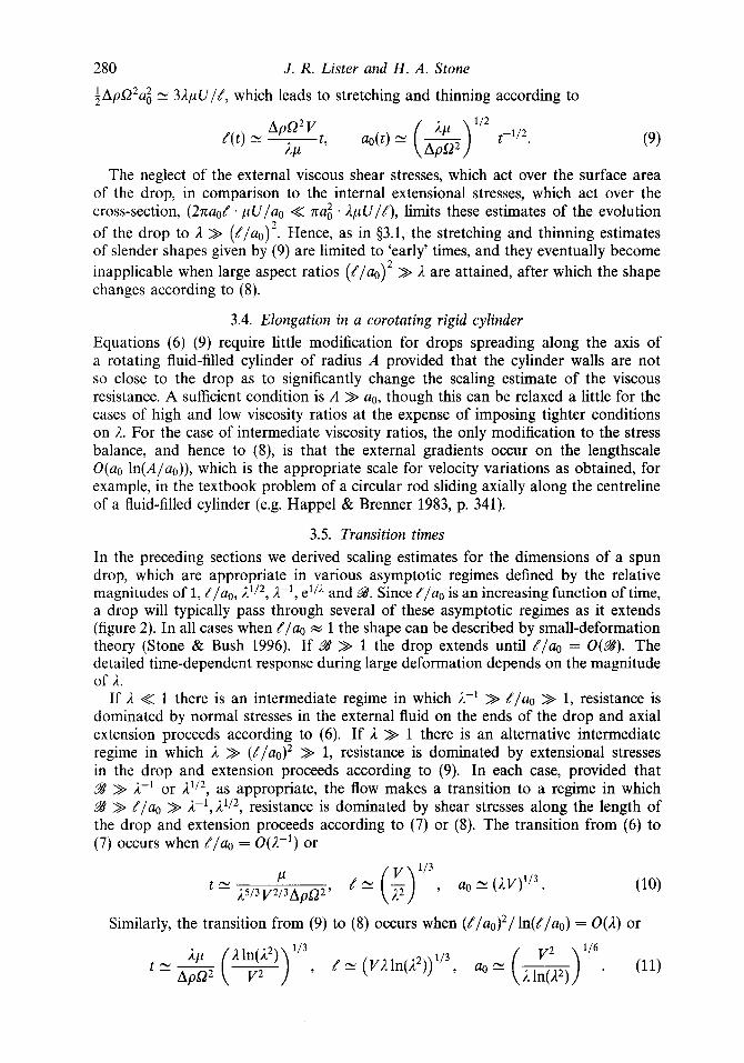
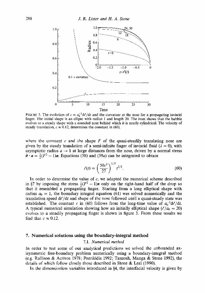
Time FIGURE 3. The evolution of c = a ~ ~ d l / d t and the curvature at the nose for a propagating inviscid finger. The initial shape is an ellipse with radius 1 and length 20. The inset shows that the bubble evolves to a steady shape with a rounded nose behind which it is nearly cylindrical. The velocity of steady translation, c = 0.12, determines the constant in (60).
where the constant c and the shape F of the quasi-steadily translating nose are given by the steady translation of a semi-infinite finger of inviscid fluid (A = 0), with asymptotic radius a ---f 1 at large distances from the nose, driven by a normal stress i? - n = i ( F 2 - 1)n. Equations (58) and (59a) can be integrated to obtain
50c2 ' I 5 /(t) = (-) t2I5.
In order to determine the value of c, we adapted the numerical scheme described in 97 by imposing the stress i ( F 2 - 1)n only on the right-hand half of the drop so that it resembled a propagating finger. Starting from a long elliptical shape with radius a. = 1, the boundary integral equation (61) was solved numerically and the translation speed dt/dt and shape of the nose followed until a quasi-steady state was established. The constant c in (60) follows from the long-time value of a ~ ~ d / / d t . A typical numerical simulation showing how an initially elliptical shape ( / / a , = 20) evolves to a steadily propagating finger is shown in figure 3. From these results we find that c w 0.12.
7. Numerical solutions using the boundary-integral method 7.1. Numerical method
In order to test some of our analytical predictions we solved the unbounded ax- isymmetric free-boundary problem numerically using a boundary-integral method (e.g. Rallison & Acrivos 1978; Pozrikidis 1992; Tanzosh, Manga & Stone 1992), the details of which follow closely those described in Stone & Leal (1990).
In the dimensionless variables introduced in 94, the interfacial velocity is given by
Deformation of a drop in a rapidly rotating denserJluid 289
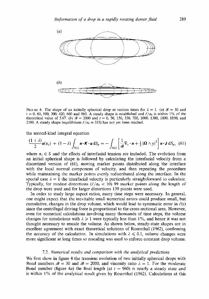
FIGURE 4. The shape of an initially spherical drop at various times for 1 = 1. (a) $A9 = 30 and t = 0, 60, 180, 300, 420, 660 and 960. A steady shape is established and / /a0 is within 1% of the theoretical value of 5.67. ( b ) $A9 = 2000 and t = 0, 50, 150, 350, 700, 1000, 1300, 1600, 1850, and 2100. A steady shape (equilibrium / / a o = 333) has not yet been reached.
the second-kind integral equation
where x, E S and the effects of interfacial tension are included. The evolution from an initial spherical shape is followed by calculating the interfacial velocity from a discretized version of (61), moving marker points distributed along the interface with the local normal component of velocity, and then repeating the procedure while maintaining the marker points evenly redistributed along the interface. In the special case il = 1 the interfacial velocity is particularly straightforward to calculate. Typically, for modest distortions ( / /a0 < 10) 99 marker points along the length of the drop were used and for larger distortions 139 points were used.
In order to study large aspect ratios, many time steps were necessary. In general, one might expect that the inevitable small numerical errors could produce small, but cumulative, changes in the drop volume, which would lead to systematic error in / ( t ) since the centrifugal driving force is proportional to the cross-sectional area. However, even for numerical calculations involving many thousands of time steps, the volume changes for simulations with A 2 1 were typically less than 1%, and hence it was not thought necessary to rescale the volume. As shown below, steady-state shapes are in excellent agreement with exact theoretical solutions of Rosenthal (1962), confirming the accuracy of the calculation. In simulations with il < 0.1, volume changes were more significant at long times so rescaling was used to enforce constant drop volume.
7.2. Numerical results and comparison with the analytical predictions We first show in figure 4 the transient evolution of two initially spherical drops with Bond numbers = 30 and 99 = 2000, and viscosity ratio il = 1. For the moderate Bond number (figure 4a) the final length (at t = 960) is nearly a steady state and is within 1% of the analytical result given by Rosenthal (1962). Calculations at this

290 J . R. Lister and H. A. Stone
I '7 G7= 100
1 ' ~~ I 0 500 1000 1500
t/( 1 +h)
FIGURE 5. Length versus the scaled time t / ( 1 + A) for Bond numbers 8 = 10,30,100 and viscosity ratios I = 0.1 (dashed), 1 (solid), 10 (dotted). Analytical predictions for the steady-state length are shown by the arrows. All the simulations except for 9l = 100 have attained steady shapes independent of the viscosity ratio and within 1% of the theoretical steady state.
Bond number with different viscosity ratios have a qualitatively similar evolution since the final steady state of the system is a rigid-body motion independent of A. For the large Bond number (figure 4b) the drop has not yet reached a steady shape in the final calculation shown (at t = 2100) since the length evolves rather slowly, O ( t In t)'I4 according to the slender-body theory in $3.2, and the equilibrium aspect ratio would be approximately / / a o = 333.
In figure 5 we illustrate the increase in length / ( t ) for various Bond numbers and viscosity ratios. Scaling time with the viscosity ratio according to t / ( 1 + A) provides an approximate collapse of simulations for the same Bond number at modest aspect ratios, indicating that the initial transient evolution tends simply to be dictated by the more viscous fluid. The results show both the initial independence of the Bond number due to the weakness of interfacial tension and the final independence of the viscosity ratio in the steady state. Establishment of the final equilibrium shape takes a rather long time since the rate of extension slows down rapidly from its initial O( 1) value.
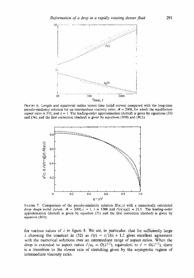
For large Bond numbers, intermediate viscosity ratios and large aspect ratios, we expect the rate of extension and thinning to be similar to the predictions of the asymptotic analysis presented in $4.1 and Appendix B. We compare numerical simulations for the case 98 = 2000 and A = 1 with the leading-order solution and higher-order correction for the length and shape in figures 6 and 7. The numerical results for the length approach the similarity solution at long times. The numerical shape (for / ( t ) / a o ( t ) rn 21.5) also compares well with the lubrication predictions, with the differences, not surprisingly, largest near the end of the drop. For both the length and the shape, the higher-order correction from Appendix B gives a modest improvement in the agreement, though we note that further corrections involve an only slowly convergent expansion in inverse powers of ln(//ao).
The solution for high viscosity ratios ( $ 5 ) is compared with numerical simulations
Deformation of a drop in a rapidly rotating denserfluid 29 1
Time, t FIGURE 6. Length and equatorial radius versus time (solid curves) compared with the long-time pseudo-similarity solution for an intermediate viscosity ratio : B = 2000, for which the equilibrium aspect ratio is 333, and i = 1. The leading-order approximation (dotted) is given by equations (33) and (34), and the first correction (dashed) is given by equations (B10) and (B11).
1 0.8
n
s 0
0.6
0 0.2 0.4 0.6 0.8 1 .o =zie
FIGURE 7. Comparison of the pseudo-similarity solution H ( q ; t ) with a numerically calculated drop shape (solid curve): B = 2000,i = 1, t = 1300 and /( t) /ao(t) w 21.5. The leading-order approximation (dotted) is given by equation (31) and the first correction (dashed) is given by equation (B10).
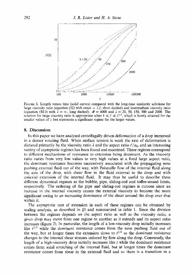
for various values of /z in figure 8. We see, in particular, that for sufficiently large L choosing the constant in (52) as t ( t ) = t/181 + 1.2 gives excellent agreement with the numerical solutions over an intermediate range of aspect ratios. When the drop is extended to aspect ratios t / a , = O(/z'/2), equivalent to t = O(1'l3), there is a transition to the slower rate of stretching given by the asymptotic regime of intermediate viscosity ratio.
292 J . R. Lister and H . A. Stone
t FIGURE 8. Length versus time (solid curves) compared with the long-time similarity solutions for large viscosity ratio (equation (52) with const. = 1.2; short dashed) and intermediate viscosity ratio (equation (B11) with I = a; long dashed): = 4000 and I = 20, 50, 150, 500 and 2000. The solution for large viscosity ratio is appropriate when 1 << / << I l l 3 , which is barely attained for the smaller values of /z but represents a significant regime for the larger values.
8. Discussion In this paper we have analysed centrifugally driven deformation of a drop immersed
in a denser rotating fluid. When surface tension is weak the rate of deformation is dictated primarily by the viscosity ratio i and the aspect ratio [ /ao, and an interesting variety of asymptotic regimes has been found and examined. These regimes correspond to different mechanisms of resistance to extension being dominant. As the viscosity ratio varies from very low values to very high values at a fixed large aspect ratio, the dominant resistance becomes successively associated with the propagating nose pushing external fluid out of the way, with Poiseuille flow of the internal fluid along the axis of the drop, with shear flow in the fluid external to the drop and with uniaxial extension of the internal fluid. It may thus be useful to describe these different dynamical regimes as the bubble, pipe, sliding-rod and toffee-strand limits, respectively. The ordering of the pipe and sliding-rod regimes is curious since an increase in the internal viscosity causes the external viscosity to become the more significant owing to an increasing dominance of the shear around the drop over that within it.
The asymptotic rate of extension in each of these regimes can be obtained by scaling analysis, as described in 93 and summarized in table 1. Since the division between the regimes depends on the aspect ratio as well as the viscosity ratio, a given drop may move from one regime to another as it extends and its aspect ratio increases (figure 2). In particular, the length of a low-viscosity drop initially increases like t2/* while the dominant resistance comes from the nose pushing fluid out of the way, but at longer times the extension slows to t1/4 as the dominant resistance changes to the internal shear stresses induced by flow along the drop. Conversely, the length of a high-viscosity drop initially increases like t while the dominant resistance comes from axial stretching of the internal fluid, but at longer times the dominant resistance comes from shear in the external fluid and so there is a transition to a

Deformation of a drop in a rapidly rotating denserfluid 293
Centrifugally driven spreading Buoyancy-driven spreading
Resistance Regime /(t) Regime R(t)
External shear l/ln(d/a) << 1 << (//a)' (tln t)'I4 h/R << 1 << R/h t'I5
Internal strain (//a)2 << a tl1 R/h << 1 (t/1)"2
Nose push 1 << a / / $15 1 << h/RIn(R/h) ( t In t)'15
Internal shear a / / << 1 << l/ln(//a) (t/1)'I4 h/Rln(R/h) << 1 << h/R (t/1)' I8
TABLE 1. Various asymptotic regimes in the problems studied here and in Koch & Koch (1995).
slower (tlnt)1/4 extension. The logarithm appears since a cylinder of radius a0 and half-length 8, sliding axially through a viscous fluid, generates an external velocity field which decays on the lengthscale a0 ln(8lao) rather than ao.
We have used an asymptotic analysis of the integral representation of Stokes flow to arrive at equations for the evolution of the drop shape and shown how analytical solutions for both intermediate and high viscosity ratios may be obtained. The asymptotic solutions are in good agreement with the full boundary-integral numerical solutions reported here. Unfortunately, we have not been able to compare the predictions with the few published experimental results since these have typically not been performed in the parameter regime appropriate to the asymptotic analysis.
The analysis of the intermediate regime blended lubrication theory with an integral representation of the external flow in a similar spirit to Lister & Kerr (1989); a related study combining these two ideas is reported by Davis, Schonberg & Rallison (1989) in a study of the lubrication force between two spherical drops. Here, it is satisfying that many of the analytical tools for viscous flow - lubrication theory, slender-body theory, viscous-thread theory, drop dynamics and integral representations - find a use in different aspects of the same problem.
It is instructive to compare our analysis of centrifugally driven axial extension of a drop to a recent study (Koch & Koch 1995) of buoyancy-driven radial spreading of a drop beneath a horizontal free surface. For the latter problem, the driving buoyancy force is O(Apgh2R), where R is now the drop radius, h is the thickness (with h << R) and the constant volume is O(R2h). Analogously to the spinning drop, the dominant resistance to radial spreading can be the push at the rim of the current, the internal shear, the external shear or the internal radial extension, for which the force estimates are O(pUUR/ ln(R/h)), O(ApUR2/h), O ( p U R ) and O(ApUh) respectively. A balance of the driving force with the dominant resistance thus gives the asymptotic spreading rates summarized in table 1. The logarithm in the first regime (low viscosity ratio; nose push), arises since the rim of the drop appears as an expanding ring of force so that the nearby flow is nearly two-dimensional and varies on the lengthscale O(h ln(R/h)). The range of the second regime (intermediate viscosity ratio; internal shear) is very narrow for buoyancy-driven spreading and was not analysed by Koch & Koch (1995). The second regime is much wider for the spinning drop and the logarithms appear for a different reason in the third regime. Hence, while there are clear analogies between the two problems, the difference in geometry leads to significant differences in behaviour and analysis.
Finally, we observe that the present analysis provides a framework for studying capillary breakup of a thread in fluid-fluid systems (Lister, Stone & Brenner 1996). This subject has been re-examined recently by Eggers (1995) and Papageorgiou (1995) with particular emphasis given to the structure of the solution near the point
294 J. R. Lister and H . A. Stone
of pinching. To date the theoretical analyses have been limited to the limit of large viscosity ratio, representative of a fluid thread in an inviscid environment, and the theoretical approach described in this paper proves useful for studies of the role of the outer fluid.
The authors thank Dr J. W. M. Bush for first suggesting this problem and the three referees for their careful reading of an earlier version of this manuscript. H.A.S. thanks the Department of Applied Mathematics and Theoretical Physics and the Institute of Theoretical Geophysics at Cambridge University for their hospitality during a visit when this work was started. Support from NSF grant CTS-8957043 is gratefully acknowledged. J.R.L. thanks the Division of Applied Sciences at Harvard University for their hospitality during a summer visit.
Appendix A. Asymptotic evaluation of the K-integral A. 1. Leading-order contribution
We wish to evaluate the integral Js n(y) K ( x , y ) u(y) dS, for slender axisymmetric shapes, where K , n and y are given by (17) and (18) and x = (O,O, z ) is a point on the centreline.
We denote the surface velocity by
u(y ) = (u, (a@, t) , 2, t ) cos 0, u, ( ~ ( 2 , t) , 2 , t ) sin 8, u, (a(?, t), 2, t ) ) (A 1)
and note that
x - y = (--acosQ,-asinO,z - 2 ) , aa
n * (x - y ) = -a - (z - 2 ) - , a5
(x - y ) 'U = -uu, + ( z - q u , .
Thus, after a little algebra, the z-component of the integral becomes
(z - Z) (u,(z - e ) - u,a) (a + (z - z)aa/ae) a d2 . (A 5) 4 L,, [a2 + ( z - z)'] 5'2
Since u, = O(u,a//), the integral may be simplified slightly by neglecting the u, term, which introduces an error O ( ( a ~ / t ) ~ ) .
We now break the range of integration into two parts and consider the integral for 13 - zI = O(a) and a << 12 - zI << t. We thus observe that the integral is dominated by the small region IZ - zI = O(a). For comparison, logarithms tend to appear when an integral is dominated by the contribution from a << 1.2 - zI << 8. We further assume that the unknowns u, (a(z, t), z , t ) and a(z, t) vary on the lengthscale t ( t ) rather than on the small scale a. Thus, in the small region IZ - zI = O(a), we can write a + (z - z)da/& = a. Hence, by using the substitution Z - z = a(z)s and extending the range of integration to s = +_a, we find that the integral is given asymptotically
or
n - K u dS, = u, (a(z, t) , z, t ) e,. I S ( , ,
Deformation of a drop in a rapidly rotating d e n s e r f i d 295
It should be noted that the neglect of terms involving the radial velocity and the use of a slowly varying assumption for the unknowns in the integrand of (A 5) introduce errors in (A 7) that are 0 ((ao/Q2 In (t?/uo)) compared to the term retained. These terms are calculated in 5A.2.
It is also possible to derive (A7) by a simple alternative argument. Once it is recognized that the dominant contribution to the value of the integral is local in character, then with the slenderness assumption (lu,l << lu,l) and the fact that u, is slowly varying, we may write u(y) = e,u,(x,) where x, = (a(z), 0, z ) is a surface point near x = (0, 0, z). Hence,
n * K - II dS,, = (l(,, n * K dS, ) * e,u,(x,). 1,‘) (A 8)
Using the Divergence Theorem and the fact that V,, - K = /6(x - y ) , we thus quickly regain (A7).
A.2. The 0 ( In ( / / a ) ) correction
It is possible to proceed to higher order in the asymptotic evaluation of the K-integral. This analysis is important for viscous threads since some small terms jump order in the large4 limit.
We begin with (A5), again neglecting the u, term since the 0(a;/e2) correction is smaller than the additional correction we now calculate. Writing
we expand the numerator of the right-hand side in a Taylor series about 5 = z . Since all integrals odd in (z - 2 ) integrate to zero, the leading-order behaviour is
where we have used the assumption that the functions uz(r,z, t ) and a2(z, t ) are slowly varying. The first integral is dominated by a local contribution from z = 2 and was evaluated in (A6). The second and third integrals are the same and are dominated by global contributions from the region a(z, t ) << Iz - 21 << / ( t ) and so give logarithms (Hinch 1991), as in (24). Consequently, we obtain
u,- In(€-’) , u,+-- ~- 2az ( aZ aa2) aZ 3 a a(uza2)
where we have neglected an 0 ( a 2 / t f 2 ) correction to the first integral in (A10) since this additional term is asymptotically smaller than the In (c’) term.
In $5 we observed that in the limit of large viscosity ratio the interior velocity profile becomes nearly uniform across the thread cross-section so that uz(r, z, t ) FZ U(z, t) , in which case we may conclude

296 J . R. Lister and H. A. Stone
Substituting (A 12) into (16) and simplifying the J-integral as before, we now obtain
instead of (21). Therefore, for 1 >> ( . t / a ~ ) ~ / 1n(c1), we have
which shows resistance with (Trouton) viscosity 311 to motion driven by the axial pressure gradient ( 1/2)aa2/az in agreement with (49).
Appendix B. Higher-order corrections to the similarity solution of $4.1 The first correction to the pseudo-similarity solution (31) and (32) is only logarithmi- cally smaller and it may be desirable to include it in order to improve the accuracy of the solution. We begin by rewriting (22) as
I d 4 dv dt aL
dL a ln(Hqi) - t? [$(qH)] (qH) + tH-
where H and r j are defined in (27),
f = V n t- and L = ln(e-'), (B 2) -112 318
and we have retained all the terms previously neglected in the leading-order analysis leading to (28). We note that the previous expression (25) for the slenderness parameter e agrees with the more careful definition in (B2) at leading order.
The leading-order solution H2(q; E) - (1 -q2)/L obtained in $4.1 involved only the first terms on the left- and right-hand sides of (B l), which are 0(L-'l2). As a result of (29), a ln(Hqi)/aL is O(L-2) rather than the expected O(L-') and so the second term on the left-hand side can be neglected at O(L-3/2). From the leading-order solution r j n cc L1I4 and E a (t In t)3/8 and hence
dL l d e 3 ___ dlnq, N -- 1 dL and - dt 4L dt - dt f dt 8t'
Thus we may integrate (B 1) to arrive at
- y l - - q = - (B 4) dH2/dq (1 - 211) dH2
dq + ~- 81 dq 8L 's' -1 [e2H(q) + (q - 7)2] ' I2
where the integration constant has been set equal to zero since H(q) should be an even function. As might be expected by analogy with other slender-body problems (e.g. Hinch 1991), the correction terms are a factor 1/L smaller than the leading terms.
We thus seek H(q;e) as an asymptotic expansion of the form
Deformation of a drop in a rapidly rotating denserfluid 297
where H t = 1 - q2. Substituting into the integral in (B4), we find that
where the first term on the right-hand side arises from HO and the second term is derived in the same manner as (24).
The first term may in fact be evaluated exactly and then expanded for small E to give
1 -qsinh-' (:&:) ___ + (e2H + (1 - q)2)1/2 - (e2H + (1 + q)2)1/2
2(1n2-1)+In
Hence, (B4) is satisfied at 0(1) and yields
+ i l n L q + i q l n ( l - q 2 ) (B8) 1 -= dHf [-:+2(1n2-1)+-- (1 - 21) dv 21
at O(L-'). Integration subject to H1 + 0 as q + 1 gives
Thus we obtain an approximation to the shape in the form
- 1-' - In( 16L) - In( 1 - q 2 ) H ( q ; E ) = (?)li2 { 1 + 8L
Finally, the correction to qn(t) is found from (29) to be
qn(t) = (2) ' I 2 ~ 5 ' ' ~ { 1 + & [ y - where
1
C = - 1 (1 - q2)1/2 In (1 - q') dq w 0.30339. (B 12)
Appendix C. A 'darn-break' solution for a half-filled cylinder In some implementations of a spinning-drop tensiometer it is reasonable to suppose
that the lighter fluid may initially occupy one end of the cylindrical working volume rather than start as a drop suspended on the rotation axis. It is thus of interest to consider the 'dam-break' solution of (43) which has initial conditions
a(z,O) = A in z < 0 and a(z,O) = 0 in z > 0.
The solution may be written in the form a2(z,t) = A2a([) where [ = z / t1 /2 , so that the governing equation is
(C 1)
- ;la' = (D(a)a')' , (C 2)

298 J . R. Lister and H . A. Stone
- I -
0 1 I I I I I
-0.15 0 0.15 0.30
5 FIGURE 9. Dam-break similarity solutions to (43) for L = 0, h, 1, 10 and co.
with
(1 - a)2
1 - (1 - P ) a 2 ’ A =
where primes denote differentiation with respect to c. The nonlinear ‘diffusivity’ D has the limiting forms
D - fa2 In(@-’) as a -+ 0 and
Thus (C2) supports solutions in which a -+ 0 or a -+ 1 at a finite value of c. Most of these solutions correspond to a point sink at a = 0 or a ring sink at a = 1. The alternative behaviour as [ -+ +a is a -+ a,, where a, is a constant, corresponding to a pre-existing infinite layer of fluid. On the border between these two forms of behaviour, as the sink strength -+ 0 and as a, -+ 0 or 1, are solutions which correspond to a propagating front. The desired unique solution that satisfies the initial conditions (C 1) is that which has a propagating front at both a = 0 and a = 1. Numerically determined solutions are shown in figure 9 for various values of 1.
D - $(l - a)3 as a -+ 1. (C 5 )
REFERENCES
BATCHELOR, G. K. 1967 An Introduction to Fluid Dynamics. Cambridge University Press. BATCHELOR, G. K. 1970 Slender-body theory for particles of arbitrary cross-section in Stokes flow.
BIRD, R.B., ARMSTRONG, R.C. & HASSAGER, 0. 1977 Dynamics of Polymeric Liquids, Vol. 1 (1st
Cox, R.G. 1970 The motion of long slender bodies in a viscous fluid. Part 1. General Theory. J.
DAVIS, R. H., SCHONBERG, J. A. & RALLISON, J. M. 1989 The lubrication force between two viscous
J. Fluid Mech. 44, 419440.
edn). John Wiley.
Fluid Mech. 44, 791-810.
drops. Phys. Fluids A 1, 77-81.
Deformation of a drop in a rapidly rotating denser fluid 299
EGGERS, J. 1995 Theory of drop formation. Phys. Fluids A 7, 941-953. ELMENDORP, J. J. & DE VOS, G. 1986 Polym. Engng Sci. 26,415417. HAPPEL, J. & BRENNER, H. 1983 Low Reynolds Number Hydrodynamics. Martinus Nijhoff. HINCH, E. J. 1991 Perturbation Methods. Cambridge University Press. Hsu, J. C. & FLUMERFELT, R. W. 1975 Rheological applications of a drop elongation experiment.
Hu, H.H. & JOSEPH, D.D. 1994 Evolution of a liquid drop in a spinning drop tensiometer. J.
HUPPERT, H. 1982 The propagation of two-dimensional and axisymmetric viscous gravity currents
JOSEPH, D. D., ARNEY, M.S., GILLBERG, G., Hu, H., HULTMAN, D., VERDIER, C. & VINAGRE, T. M.
KOCH, D. M. & KOCH, D. L. 1995 Numerical and theoretical solutions for a drop spreading below
LISTER, J.R. & KERR, R.C. 1989 The propagation of two-dimensional and axisymmetric viscous
LISTER, J. R., STONE, H. A. & BRENNER, M. P. 1996 Capillary breakup of a viscous thread in the
MANGA, M. & STONE, H. A. 1993 Buoyancy-driven interactions between two deformable viscous
PAPAGEORGIOU, D. T. 1995 On the breakup of viscous liquid threads. Phys. Fluids A 7, 1529-1544. POZRIKIDIS, C. 1992 Boundary Integral and Singularity Methods For Linearized Viscous Flow. Cam-
bridge University Press. RALLISON, J. M. & ACRIVOS, A. 1978 A numerical study of the deformation and burst of a viscous
drop in an extensional flow. J. Fluid Mech. 89, 191-200. ROSENTHAL, D. K. 1962 The shape and stability of a bubble at the axis of a rotating liquid. J. Fluid
Mech. 12, 358-366. STONE, H. A. & BUSH, J. W. M. 1996 Time-dependent drop deformation in a rotating high viscosity
fluid. Q. Appl. Maths (in press). STONE, H.A. & LEAL, L.G. 1990 The effect of surfactants on drop deformation and breakup. J .
Fluid Mech. 220, 161-186. TANZOSH, J., MANGA, M. & STONE, H. A. 1992 Boundary integral methods for viscous free-boundary
problems : Deformation of single and multiple fluid-fluid interfaces. In Proc. Boundary Element Technologies VZZ (ed. C. A. Brebbia & M. S. Ingber), pp. 19-39. Computational Mechanics Publications.
TAYLOR, G.I. 1964 Conical free surfaces and fluid interfaces. In Proc. 11th Zntl Cong. Appl. Mech., Munich, pp. 790-796.
VONNEGUT, B. 1942 Rotating bubble method for the determination of surface and interfacial tension. Rev. Sci. Instrum. 13, 6-9.
Trans. SOC. Rheol. 19, 523-540.
Colloid Interface Sci. 162, 331-339.
over a rigid horizontal surface. J . Fluid Mech. 121, 43-58.
1992 A spinning-drop tensioextensometer. J . Rheol. 36,621-662.
a free fluid surface. J. Fluid Mech. 287, 251-278.
gravity currents at a fluid interface. J. Fluid Mech. 203, 215-249.
presence of an external fluid (in preparation).
drops. J . Fluid Mech. 256, 647-683.