timber roof structure for outdoor auditorium in parque
TRANSCRIPT

Proceedings of the International Association for Shell and Spatial Structures (IASS) Symposium 2009, Valencia Evolution and Trends in Design, Analysis and Construction of Shell and Spatial Structures
28 September – 2 October 2009, Universidad Politecnica de Valencia, Spain Alberto DOMINGO and Carlos LAZARO (eds.)
Timber roof structure for outdoor auditorium in Parque Paraíso, San Blas (Madrid)
Arturo ANTÓN*, Antonio G. MEIJIDE, Jesús J. CORBAL
*TEMHA, SL As Pezocas, Chalet 1B, 15173 Oleiros. A Coruña. Spain
Abstract A timber shell structure is designed to provide covering for an outdoor auditorium in Madrid (Spain). The covering comprises five independent overlapped marquees with similar shape but diverse dimensions. The surface geometry of each marquee is defined by a hyperbolic paraboloid, with its boundaries delimited by elliptical curves in horizontal projection. Structural section for the timber shell is a composite section with several staggered layers of straight sawn timber planks, arranged in two orthogonal directions following the straight skew lines of the hyperbolic paraboloid. Over them two continuous top layers are arranged which provides bracing for the structure and support for the waterproofing material. Each layer is laid over the previous one, bolted and glued with polyurethane adhesive. Special characteristics of the design analysis and detailed erection process are described. The designed solution provides lightweight roofing with a powerful and original image, short construction time and reasonable budget. Keywords: Timber shell, spatial structures, ribbed shells, saddle-shaped roof shells, nailed planks.
1. Introduction Timber is one of the oldest structural materials. Actual technology for joints, adhesives and protective treatments allows the development of more ambitious projects that reach the formal and technological limits of the material. The advantageous specific resistance of structural timber makes the design of light-weight roof structures and specially shell structures one of its most attractive and interesting implementations. Additionally, ecological concerns become more important nowadays and timber is one of the best suited materials for construction due the low energy consumption necessary for production, Natterer [1]. This paper describes the process of design, analysis and erection of a singular timber roof structure for an auditorium located at Parque Paraíso, San Blas (Madrid, Spain).
468

Proceedings of the International Association for Shell and Spatial Structures (IASS) Symposium 2009, Valencia Evolution and Trends in Design, Analysis and Construction of Shell and Spatial Structures
The new roofing is part of a restyling project for an old outdoor auditorium. It was necessary to provide protection against weather conditions, while not interfering with visibility from every covered area to the scenario, by avoiding supporting elements. Favourable acoustic properties were demanded too, and it was desired to provide a new and powerful image for the whole project. The position of the auditorium inside San Blas Park (Figure 1) pointed that a timber structure solution could be perfectly integrated with the natural surroundings and the necessity to avoid supports made a light shell structure a very convenient solution.
Figure 1: Auditorium location and surroundings
The adopted solution to satisfy the required demands consists in a set of five independent overlapped marquees with similar shape but diverse dimensions (Figure 2) that cover the whole facility. One of the marquees covers the stage, while the rest of them cover the spectators area and a nearby outdoor bar counter. The surface of each marquee is defined by a hyperbolic paraboloid, with its boundaries delimited by two elliptical curves in horizontal projection. The behaviour of this saddle-shaped shell roofs has been investigated in the past by Oiger [2] through experimental research and numerical analysis.
Figure 2: Elevation view of the timber shells
Covered area for each marquee varies from 61 m2 for the smaller one that covers the bar counter, to 601 m2 for biggest over the spectators area with axis of 30x27m. The whole set covers a total area of 1400 m2. The structural section for each marquee shell is a composite section with several staggered layers of straight sawn timber members, arranged in two orthogonal directions following the straight skew lines of the hyperbolic paraboloid. Over them two continuous top layers are arranged which provide bracing for the structure and support for the waterproofing
469

Proceedings of the International Association for Shell and Spatial Structures (IASS) Symposium 2009, Valencia Evolution and Trends in Design, Analysis and Construction of Shell and Spatial Structures
material. Each of the marquees has a different number of timber layers and different composite section, according to its overall size and internal forces. Each layer is laid over, bolted and glued with polyurethane adhesive to the previous one. The structure is built over a temporary self bearing formwork that supports the first layer of the hyperbolic paraboloid. Each of the marquees is supported by two steel supports located on both sides of its minor axis. The supports have the shape of an inverted double omega and are designed with circular hollow steel sections of diverse dimensions. The diameter of the CHS section for the bigger marquee was Ø219mm with 15mm wall thickness.
2. Structural configuration, materials and joints The structure is formed with pinewood (Pinus sylvestris) planks, strength class C-30 according to EC-5, imported from the north of Europe and treated for Service Class 3. The individual planks are selected, avoiding knots and defects, and joined to their final length by a finger-joint type connection. Section dimensions for each member are 140x34mm for the bottom layers, and 140x20mm for the upper bracing layers (Figure 3).
Figure 3: Structural section for the each marquee type
The in-situ connections between each layer are accomplished with a mono-component polyurethane adhesive, resistant to water and high temperatures and designed for joining structural wood. Adhesive quality is D4 according to DIN/EN 204. The commercial name for the product is Plaster Pur-20 Estructuras, manufactured by BAKAR. In order to configure an adequate connection between the planks is necessary to provide a pressure of 0.6 N/m2 after applying the glue. This pressure is provided by screw gluing [3] to the previous layer after placing the adhesive. The curing time for the adhesive is about 4 hours at 20ºC. To apply the pressure, 39mm length and Ø6mm HECO Topix screws where selected. The fastening by mechanical means to a pre-specified par assured that the minimum required pressure was achieved. This way a composite section is obtained with planks oriented in two orthogonal directions.
470

Proceedings of the International Association for Shell and Spatial Structures (IASS) Symposium 2009, Valencia Evolution and Trends in Design, Analysis and Construction of Shell and Spatial Structures
Between the first and second layer, acoustic insulating wood elements are inserted between the structural ones to ensure an adequate acoustic behavior (Figure 4). These elements are perforated with vertical drillings that improve their acoustic behavior. They do not intervene in general structural design.
Figure 4: Timber planks arrangement views from under and over the structure
The two upper layers are continuous in both directions and fulfil a double function: act as bracing for the general structural scheme and provide support for the waterproofing system. The timber members of the upper layers are contiguously arranged so they keep lateral contact. In order to achieve the transversal continuity and to reduce horizontal curvatures and bending in the wood members, it is necessary to intercalate variable width wood planks (tapered). This is due to the variation of the torsion angle along the longitudinal axis of the plank to adapt to the surface geometry. This configuration allows that planks of the upper layers keep their axis aligned with the inferior layer planks axis.
Figure 5: Plank orientation and reinforced zones.
In the lower layers, there are several solid zones in which the timber planks are placed contiguously as in the upper layers (Figure 5). These zones are located in two triangular areas near the supports. This configuration allows achieving greater stiffness and resistance where it is needed. There are contiguous areas as well all along the border beam that ease the connection with the perimeter steel element and provide structural reinforcement for the wood-steel interface.
471

Proceedings of the International Association for Shell and Spatial Structures (IASS) Symposium 2009, Valencia Evolution and Trends in Design, Analysis and Construction of Shell and Spatial Structures
3. Structure Analysis Structure design has been performed according to EC-5 and Spanish Code CTE-DB-SE-M for wood design. A frame element model is employed to study the behavior of the structure. Because of the existing differences in size and section of each of the marquees, a specific model for each of them had to be considered.
Figure 6: Analysis model for one of the roof shells
Structural model (Figure 6) represents by means of frame elements the two main families of planks along the straight lines of the hyperbolic paraboloid. The bracing for the reticular structure is achieved through the effect of the upper layers that are represented with diagonal elements. Properties for these diagonal elements are obtained using a specific local finite element model that evaluates their combined in-plane stiffness and strength (Figure 7). The border beam and the stiffness of the supporting system are represented with frame elements.
Figure 7: Complete model mesh and local bracing analysis
As the timber planks are arranged in the straight directions of the hyperbolic-paraboloid, they experiment an axial rotation to adapt to the surface geometry. Because of this, there is an initial state of torsion stresses that have to be considered additionally to the stresses obtained in the analysis model. The border beams receive the loads from the timbers planks and work mainly with compressive axial forces and bending (Figure 8). There are two different structural sections for the border beams; the most resistant one is located near the supports. This section works
472

Proceedings of the International Association for Shell and Spatial Structures (IASS) Symposium 2009, Valencia Evolution and Trends in Design, Analysis and Construction of Shell and Spatial Structures
with major bending moments as it has to distribute the punctual loads from the CHS pipes to the timber shell.
Figure 8: Contour beam geometry and section
Buckling analysis was performed in two phases: First a non-linear buckling analysis through modal analysis is performed, obtaining the first buckling modes and safety coefficients. Considering these modes, equivalent buckling lengths are determined for each member and code checks are performed using amplification coefficients for axial stresses. Additionally, for the most unfavourable load case, a non-linear p-delta analysis is accomplished amplifying loads till maximum allowable stress is achieved, to obtain a global safety coefficient.
4. Erection of the structure Erection of the structure begins with the assembling of a temporary falsework with steel pillars and timber beams, which are aligned with the straight lines of the final surface. The falsework is designed to resist the structure own weight and constructive live loads.
Figure 9: Temporary Support Structure and first layer placement
Over the wooden beams, the first layer of planks is arranged into its position, as well as the reinforced areas. The following layers are bolted and glued over the previous ones. Over them two upper contiguous bracing layers are built.
473
Proceedings of the International Association for Shell and Spatial Structures (IASS) Symposium 2009, Valencia Evolution and Trends in Design, Analysis and Construction of Shell and Spatial Structures
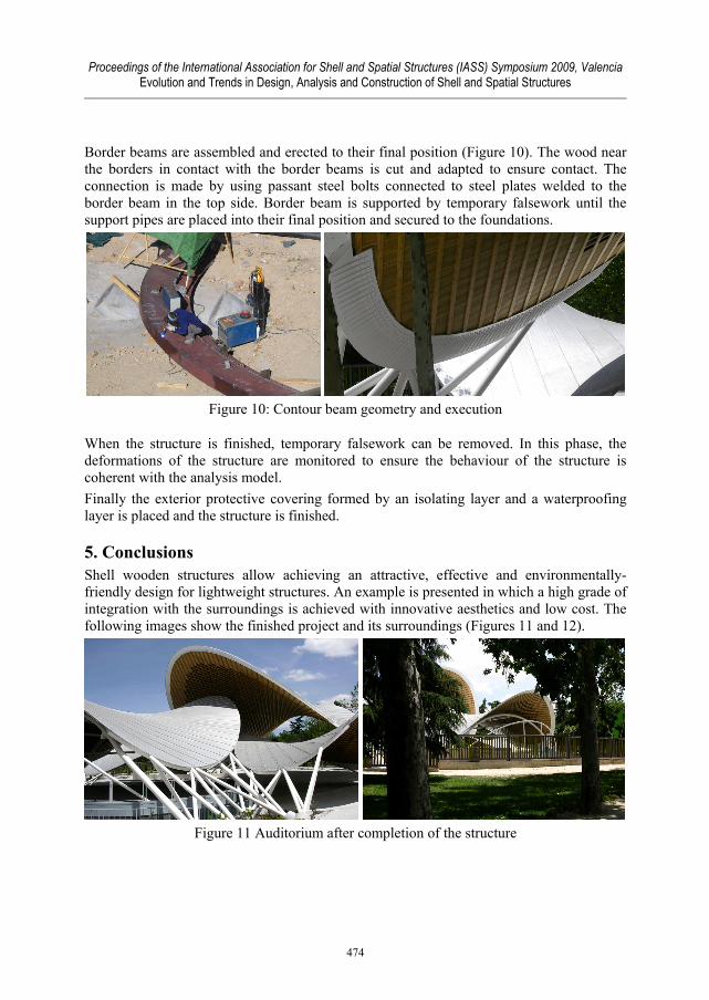
Border beams are assembled and erected to their final position (Figure 10). The wood near the borders in contact with the border beams is cut and adapted to ensure contact. The connection is made by using passant steel bolts connected to steel plates welded to the border beam in the top side. Border beam is supported by temporary falsework until the support pipes are placed into their final position and secured to the foundations.
Figure 10: Contour beam geometry and execution
When the structure is finished, temporary falsework can be removed. In this phase, the deformations of the structure are monitored to ensure the behaviour of the structure is coherent with the analysis model. Finally the exterior protective covering formed by an isolating layer and a waterproofing layer is placed and the structure is finished.
5. Conclusions Shell wooden structures allow achieving an attractive, effective and environmentally-friendly design for lightweight structures. An example is presented in which a high grade of integration with the surroundings is achieved with innovative aesthetics and low cost. The following images show the finished project and its surroundings (Figures 11 and 12).
Figure 11 Auditorium after completion of the structure
474

Proceedings of the International Association for Shell and Spatial Structures (IASS) Symposium 2009, Valencia Evolution and Trends in Design, Analysis and Construction of Shell and Spatial Structures
Figure 12 Interior and exterior views
Acknowledgement To Cleto Barreiro Sorrivas, Madrid city council, architect of the auditorium. To Fernando Caramés Gómez, for his contribution in timber detailing and assembly of the structure.
References [1] Julious K. Natterer. Design and construction of Timber Space Structures. , in IASS
2001. Theory, Design and Realization of Shell and Spatial Structures. [2] Karl Oiger. Design and Erection of Saddle-Shaped Wooden Shell Roofs. Innovative
Wooden Structures and Bridges, IABSE Conference, Lahti, 2001 [3] Kairi, M., Kaloinen, E. & Koponen, S. Screw gluing Laminated Veneer Lumber
structures with polyurethane (PU). World Conference on Timber Engineering 2000, Whistler, Canada s. 4.4.3-1-8.
475