tilobe - keystonedental.com · dear customer, thank you for allowing keystone dental inc. the...
TRANSCRIPT

Smarter Thinking. Simpler Design.
Prosthetic Manualfor PrimaConnex® & Genesis implants
TiLobe®

Dear Customer,
Thank you for allowing Keystone Dental Inc. the opportunity to provide solutions which we
hope meet or exceed your expectations.
Keystone Dental Inc. produces innovative, high quality dental implants, accessories, and
biologics and distributes these products globally. Our headquarters are in Burlington,
Massachusetts and we have state-of-the-art manufacturing facilities in both Burlington and
Irvine, California.
Our range of implant products is broad, fulfilling both niche and standard requirements
for all specialties. If you wish, at any time, to discuss Keystone Dental products, ongoing
developments, and future research, or if you have any suggestions which you feel would
help us serve you better, please call me directly at (781) 328-3387 or Toll Free at (866)
902-9272.
Again, thank you for allowing Keystone Dental, Inc. to satisfy your implant requirements, and
I look forward to speaking with you in the future.
Michael A. KehoeKeystone Dental, Inc.President & CEO

3
TABLE OF CONTENTS
Introduction Design Features ............................................................................................................................................................. 4Dimensions ..................................................................................................................................................................... 5Treatment Planning ........................................................................................................................................................ 5Healing Abutments ........................................................................................................................................................ 6Consistent Contours ....................................................................................................................................................... 6Torque Wrench Procedure .............................................................................................................................................. 7Cleaning and Sterilization Procedure ........................................................................................................................... 7
Restorative Options Cement-Retained Restorations ...................................................................................................................................... 8Screw-Retained Restorations ......................................................................................................................................... 8Implant Overdenture Restorations ................................................................................................................................ 9Implant- or Bar-Retained Overdenture Restorations ................................................................................................... 9
Impression Techniques Open Tray (Direct) Impression Post Technique ........................................................................................................... 12Closed Tray (Indirect) Impression Post Technique ...................................................................................................... 12Laboratory Cast Fabrication .......................................................................................................................................... 13
Temporization Procedures Screw-Retained Temporization – Chairside ................................................................................................................. 14
Cement-Retained Restorations Esthetic Contour Ti Abutment ...................................................................................................................................... 16
a. Lab Preparation of the Esthetic Contour Ti Abutment .................................................................................... 17b. Chairside Preparation of the Esthetic Contour Ti Abutment ............................................................................ 20
UCLA Gold/Plastic Sleeve – Custom Abutment .......................................................................................................... 23Quick-Abutment System ................................................................................................................................................ 27
Screw-Retained Restorations UCLA Abutment System ................................................................................................................................................ 34
LOCATOR Abutment System How to use the LOCATOR Tool .................................................................................................................................... 39Chairside Placement of the LOCATOR Abutment – New Denture ........................................................................... 40Chairside Placement of the LOCATOR Abutment – Existing Denture ...................................................................... 42Reline and Rebase a LOCATOR Case ......................................................................................................................... 44
Snap Abutment System Chairside Placement of the Snap Abutment – New Denture .................................................................................. 45Chairside Placement of the Snap Abutment – Existing Denture ............................................................................ 48Reline and Rebase a Snap Case ............................................................................................................................... 49
Bar-Attachment Retained OverdenturesBar Overdenture Restorations Using the UCLA Abutment System ........................................................................... 50

4
Introduction
This manual serves as a reference to aid clinicians and dental technicians in restorative procedures for Keystone Dental’s TiLobe connection implants (PrimaConnex® and Genesis) and prosthetic components. It is not intended to describe the methods or procedures for diagnosis, treatment planning, placement or restoration; nor does it replace clinical training or clinical judgment regarding the needs of each patient.
Keystone Dental recommends appropriate training as a prerequisite for the placement/restoration of implants and associated treatment. The procedures described within this manual reflect idealized patient presentations with conditions adequate for commencement of the restorative phase of treatment. No attempt has been made to cover the wide range of actual patient conditions which may adversely affect prosthetic outcomes.
Design Features
TiLobe connection implant systems share three diameter prosthetic platforms with a secure, patented internal 6-lobed connection to allow complete cross-compatibility between the systems. The TiLobe connection utilizes the same screw diameter throughout all implant diameters.
Introduction & Characteristics
8.5˚ Taper
6-Lobe Connection
Pilot

5
Dimensions
TiLobe implants are available in a variety of platform diameters and lengths. The label icons below identify the prosthetic components that will mate with each platform diameter and represent the diameter compatibility of the prosthetic connections of the TiLobe implant systems.
Identifies all 4.0 and 5.0 flare prosthetic components that will mate with the Ø3.5 mm and Ø3.8 mm implants.
Ø3.5 mm and Ø3.8 mm implants are available in lengths of 8.5 - 16 mm.
Identifies all 5.0 and 6.0 flare prosthetic components that will mate with the Ø4.1 mm and Ø4.5 mm implants.
Ø4.1 mm and Ø4.5 mm implants are available in lengths of 8 - 16 mm.
Identifies all 5.0 flare prosthetic components that will mate with the Ø5.0 mm and Ø5.5 mm implants.
Ø5.0 mm and Ø5.5 mm implants are available in lengths of 8.5 - 15 mm.
Identifies all 6.0 flare prosthetic components that will mate with the Ø6.5 mm implants.
Ø6.5 mm implants are available in lengths of 8.5 - 13 mm.
* For specifics on implant lengths please refer to the Keystone Dental TiLobe Product
Catalog. All products may not be available in all markets.
Treatment Planning
Successful treatment requires the coordinated efforts of the implanting surgeon, the restorative dentist, and the dental technician. A pre-surgical treatment option discussion between these individuals helps to determine the appropriate restorative strategy and adds balance between the surgical objectives and esthetics, phonetics, and function of the final prosthesis. In addition, this coordinated approach ensures that treatment is complete, there is no omission of important technical considerations, such as the use of a surgical guide for implant positioning, and that the biomechanics of the final prosthesis is maintained.
DIAGNOSTIC CASTS
Mounted study casts and a diagnostic wax-up are the foundation for determining implant location. The implanting surgeon, the restoring dentist, and the dental technician should work together to produce diagnostic wax-ups and a surgical guide.
SURGICAL GUIDES
A surgical guide is used to indicate practical boundaries for the placement of implants and may prevent them from being placed too buccal/lingually or mesial/distally. This process helps to ensure functional placement of implants and esthetic results. The implanting surgeon should communicate to the dental technician any conditions that may affect guide design (e.g., the type of incision that will be used, expected reflection of tissue, etc.) The designed surgical guide also provides information relating to ideal tooth shape and supporting bone structures that may have been lost.
Introduction & Characteristics
3.53.8
5.04.13.5
3.53.8
5.04.13.5
3.53.8
5.04.13.5
3.53.8
5.04.13.5
3.53.8
5.04.13.5
3.53.8
5.04.13.53.53.8
5.04.13.5

6
Healing Abutments
The healing abutment is a one-piece component, designed to support optimal esthetic results. This abutment is used for soft tissue contouring during the healing phase and can be used for both one- and two-stage surgeries.
Intended Applications
• For all positions in the mouth
• For intermediate use only
Recommended Torque – 10 Ncm
The healing abutment is laser etched with numbers to identify implant diameter, contour and height of the healing abutment.
Consistent Contours
Keystone Dental TiLobe prosthetics offer a complete line of restorative products with consistent contours from healing abutments, temporary abutments, and impression copings to the final abutments for each prosthetic platform. If the surgeon has placed a specific flared healing abutment, it is important to use components with the same emergence profile throughout the treatment plan. This will ensure easy seating of prosthetic components and support of the soft tissue contours, without causing discomfort for the patient by blanching of the soft tissue.
The chart below defines the available contours for each prosthetic platform.
Healing Abutment
Temporary Abutment
ContouredImplant
Impression Post
Esthetic Contour Ti Abutment
Quick-Abutment
Introduction & Characteristics
4.5Ø identifies the diameter of the implant
3 identifies the height of the healing abutment
5.0 identifies the flare of the healing abutment
Implant Diameter Available FlaresØ3.5, Ø3.8 4.0 mm 5.0 mm
Ø4.1, Ø4.5 5.0 mm 6.0 mm
Ø5.0, Ø5.5 5.0 mm 6.0 mm
Ø6.5 6.0 mm

7
Torque Wrench Procedure
The measurement of torque is extremely important in the success of restorative procedures. All TiLobe final abutment screws have a recommended torque of 30 Ncm. To assure proper torque is applied, set the wrench to the desired value by turning the torque meter dial until the desired torque value is shown in the window on the handle of the torque wrench. Align the marking on the torque meter dial with the markings on either side of the window. To apply torque to the abutment screw, turn the wrench slowly in a clockwise direction.
NOTE: The word “IN” should appear on the top of the wrench when turning in a clockwise direction.
Continue turning until the wrench “slips.” When the wrench slips a clicking sound is heard and tension is released on the torque wrench. This indicates that the pre-set torque value has been reached and assures that the proper torque value has been delivered.
For additional information and cleaning/sterilization instructions, please refer to the Surgical Ratchet/Torque Wrench Instructions For Use.
NOTE: It is recommended to torque the TiLobe final abutment screw twice. First torque the abutment screw to the recommended 30 Ncm. Allow 10 minutes for screw relaxation and then torque again to the recommended 30 Ncm.
Cleaning and Sterilization Procedure
Certain prosthetic components are provided in sterile, gamma irradiated packaging. Please refer to individual package labeling to determine if the prosthetic component is sterile. Before installation, non-sterile abutments must undergo a cleaning and sterilization procedure. This procedure should preferably take place in an ultrasonic unit with a mixture of dishwashing detergent and water. For sterilization procedures, follow the instructions below:
Abutment Sterilization ProcedureTi Temporary Abutment
UCLA Gold/Plastic Abutment*
Steam Sterilization Gravity Cycle: 134°C (~ 273°F) 20 minute exposure / 40 minute dry time
Steam Sterilization Pre Vacuum Cycle: 134°C (~273°F) 4 minute exposure / 40 minute dry time
Healing Abutment
Impression Posts
PMMA Temporary Abutment
Esthetic Contour Ti Abutment
Quick-Abutment
Final Abutment Screw
LOCATOR® Abutment
Snap Abutment
Not required. Sterile when delivered.
CAUTION: Do not steam autoclave plastic parts.
*It is recommended that the finished custom UCLA abutment from the dental laboratory be sterilized according to sterilization procedures listed above for the UCLA Gold/Plastic Abutment.
Introduction & Characteristics

8
Restorative Options
Cement-Retained Restorations
Cement-retained implant restorations are very similar to traditional crown and bridge restorations. An abutment is prepared and is screwed onto the implant. The screw access hole is protected for retrieval of the abutment, if necessary. The restoration is cemented to the prepared abutment.
a. Intended Applications
• Single or multiple-unit implant restorations.
• Fully or partially edentulous arch.
• All tooth positions.
b. Advantages
• Use of conventional crown and bridge techniques.
• Maintaining of optimum occlusal integrity by the intact occlusal surface of the cement-retained restoration.
• Flexibility to achieve optimal esthetics.
c. Disadvantages
• Difficulty in retrieving the restoration, if necessary.
Screw-Retained Restorations
Screw-retained restorations are indicated when inter-arch space is limited and/or a screw-retained restoration is planned. In this application, the abutment and restoration are all one piece, seated on the implant, and retained by a screw that enters through the occlusal surface of the prosthesis.
a. Intended Applications
• Single or multiple-unit implant restorations.
• Fixed-detachable (hybrid-type) restorations.
• Fully or partially edentulous arch.
• All tooth positions.
b. Advantages
• Ease of retrievability for hygiene maintenance.
• Minimal inter-arch space is required.
c. Disadvantages
• Splinted restorations on implants with divergent angles greater than 10°.
• Screw holes for wider implants may be highly unesthetic.
Restorative Options

9
Restorative Options
Implant Overdenture Restoration - Attachment-Retained
The denture is retained in the mouth with an attachment mechanism supported by tissue. It contains a metal housing and a retentive insert to secure the denture to the implant abutments. The abutments screw directly into the implant, providing a choice of retention options.
a. Intended Applications
• Maladaptive or dissatisfied denture patients requiring greater retention and oral comfort.
• Patients who desire a more stable mandibular denture.
• Partially edentulous patients with severely compromised dentition (i.e., about to become edentulous) that cannot be successfully maintained to retain or support a prosthesis.
• Ideally Canine or Lateral Position to reduce tendency for denture to rotate around the fulcrum.
b. Advantages
• Prosthesis is removable for easier oral hygiene access.
• Existing denture may be used.
• Low financial investment by the patient.
c. Disadvantages
• None when contraindications are not present.
d. Number of implants
• In the mandible, two to four implants are recommended for an Implant Overdenture Restoration - Stud Type.
• In the maxilla, a minimum of four implants are recommended for an Implant Overdenture Restoration - Stud Type.
Implant- or Bar-Retained Overdenture Restorations
Screw-retained restorations are also used for bar-supported and/or implant-supported overdenture cases. The denture is retained by the bar with attachments, i.e. clips or ball attachments or fixed directly to the bar and screwed to the implants (Fixed-detachable or Hybrid types).
NOTE: An implant-retained, tissue-supported prosthesis is indicated when there are fewer than four implants in the mandible and fewer than six in the maxilla.
a. Intended Applications
• Multiple-unit restorations.
• Areas where extensive bone loss has occurred.
• Excessive inter-occlusal space.
• Fully edentulous patients in the maxillae or mandible.
Restorative Options
10
b. Advantages
• Bar-supported overdenture:
– Easily removed by patient.
– Easier hygiene maintenance by patient.
• Implant-supported overdenture:
– Fixed (not removable).
c. Disadvantages
• Inter-occlusal space between the maxilla and mandible is limited.
d. Number of implants
• In the mandible, four to six implants are recommended for an implant-supported/implant-retained prosthesis.
• In the maxilla, six to ten implants are recommended for an implant-supported/implant-retained prosthesis.
Restorative Options

11
Impression Techniques
There are three (3) types of impression techniques utilized in implant dentistry:
Prepared Abutment – An abutment is placed and prepared in the mouth using copious amounts of irrigation. The abutment screw is tightened to the recommended torque. An impression is taken with the prepared abutment in place.
Implant-level – The healing abutment is removed and an impression post is placed on the implant. An impression is taken to transfer the lobe position, angle, contour of the tissue and depth of the implant.
Abutment-level – The healing abutment is removed and an unprepared abutment is seated on the implant in the patient’s mouth. An impression post or impression cap is placed onto the abutment. The abutment and abutment screw position are recorded for screw- or cement-retained prosthesis.
Implant-level and Abutment-level impressions can be made by either of the following techniques:
• Open Tray (Direct) Pick-up Impression Technique
• Closed Tray (Indirect) Impression Technique
The option chosen is dependent on the treatment plan and the degree of accuracy needed to fabricate the final restoration. The open tray technique is considered more accurate than the closed tray technique and is recommended in multiple-unit restorations. Impression posts for the TiLobe connection are packaged with a short and long screw for use in either open or closed tray impressions.
To select the proper platform diameter open or closed tray impression post(s), match the color of the post to the implant diameter located on the label. Selection of the proper contour should be consistent with the contour of the healing abutment.
Open Tray (Direct) Pick Up Impression Post
This technique requires use of an impression post body and a long screw. The open tray impression post transfers the position of the internal 6-lobes, angle of the implant, contours of the tissue and depth of the implant in the osteotomy. Open tray impression posts are recommended for use when an impression is made of multiple divergent implants.
Closed Tray (Indirect) Impression Post
This technique requires use of an impression post body and a short screw. The closed tray impression post transfers the position of the internal 6-lobes, angle of the implant, contours of the tissue and depth of the implant in the osteotomy. Closed tray impression posts are ideal for use in limited inter-arch space.
Impression Post Body
Long Screw
Impression Techniques
Impression Post Body
Short Screw

12
Procedure For Open Tray (Direct) Pick Up Impression Post Technique(Example shown is a 4.1/4.5 mm TiLobe® connection implant with a 5.0 mm flare healing abutment)
Step 1
The 5.0 mm flare healing abutment is removed with the quad driver.
Step 2
The impression post is positioned into the internal TiLobe of the implant and fully seated with the quad driver.
NOTE: Take a radiograph to verify the proper fit between the impression post and the implant.
Step 3
It is recommended to locate the screw head to facilitate access after the impression and prevent impression material from obstructing the screw head. A light or medium body impression material is injected around the implant/impression post junction at the gingival aspect. Then the customized impression tray is completely filled with heavy body or putty impression material and fully seated to take the impression.
Step 4
Once the impression material has set, the screw of the impression post is loosened and the impression with the impression post is removed. The analog is then attached to the impression post and the impression post/ analog assembly, with the retention screw is sent to the laboratory, including an impression of the opposing arch and a proper jaw relation record. The healing abutment is placed onto the implant or a temporary crown is seated.
Step 5
Once the dental stone has fully set, remove the long screw and the impression post tray from the cast. At this time, abutment choices are finalized and the restoration fabricated.
For a chairside fabricated temporary crown, place the Temporary (PMMA) or Ti (Titanium) Temporary Abutment using the quad driver and shorten to the appropriate occlusal scheme. The Final Abutment Screw is torqued at 20 Ncm onto the implant. Then the crown, fabricated chairside or previously provided by the laboratory, is placed.
Procedure For Closed Tray (Indirect) Pick Up Impression Post Technique(Example shown is a 4.1/4.5 mm TiLobe® connection implant with a 5.0 mm flare healing abutment)
Step 1
The 5.0 mm flare healing abutment is removed with the quad driver.
Step 2
The impression post is positioned into the internal TiLobe of the implant and fully seated with the quad driver.
Impression Techniques

13
NOTE: Take a radiograph to verify the proper fit between the impression post and the implant.
Step 3
A light or medium body impression material is injected around the implant/impression post junction at the gingival aspect. Then the customized impression tray is completely filled with heavy body or putty impression material and fully seated to take the impression.
Step 4
Once the impression material is completely set, the impression tray can be removed leaving the impression post still attached to the implant. The impression post can now be removed and transferred back into the impression. The impression post must be completely seated with the correct orientation, preferably under magnification. The impression with the impression post/ analog assembly and screw is sent to the laboratory, including an impression of the opposing arch and a proper jaw relation record. The healing abutment is placed onto the implant or a temporary crown is seated.
Step 5
Once the dental stone has fully set, remove the impression tray and the posts from the cast. At this time, abutment choices are finalized and the restoration is fabricated.
For a chairside fabricated temporary crown, place the Temporary (PMMA) or Ti (Titanium) Temporary Abutment using the quad driver and shorten to the appropriate occlusal scheme. The Final Abutment Screw is torqued at 20 Ncm onto the implant. Then the crown, fabricated chairside or previously provided by the laboratory, is placed.
Laboratory Cast Fabrication – Dental Laboratory
Step 1
Once the impression, bite, opposing model, shade and instructions have been received by the dental laboratory, inspect the impression for accuracy.
Step 2
Please refer to IMPRESSION TECHNIQUES, Open Tray (Direct) Technique or Closed Tray (Indirect) Technique for attaching of implant analog if the clinician did not attach the analog prior to sending the case to the laboratory.
Step 3
A soft tissue model is recommended to be made around the implant site.
Step 4
Pour a working cast in minimal expansion, high hardness die stone. Articulate according to normal laboratory procedures.
Impression Techniques
14
Temporization Procedures
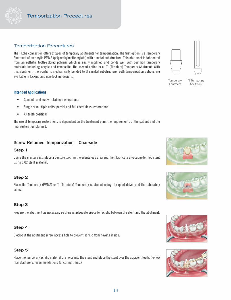
The TiLobe connection offers 2 types of temporary abutments for temporization. The first option is a Temporary Abutment of an acrylic PMMA (polymethylmethacrylate) with a metal substructure. This abutment is fabricated from an esthetic tooth-colored polymer which is easily modified and bonds well with common temporary materials including acrylic and composite. The second option is a Ti (Titanium) Temporary Abutment. With this abutment, the acrylic is mechanically bonded to the metal substructure. Both temporization options are available in locking and non-locking designs.
Intended Applications
• Cement- and screw-retained restorations.
• Single or multiple units, partial and full edentulous restorations.
• All tooth positions.
The use of temporary restorations is dependent on the treatment plan, the requirements of the patient and the final restoration planned.
Screw-Retained Temporization – Chairside
Step 1
Using the master cast, place a denture tooth in the edentulous area and then fabricate a vacuum-formed stent using 0.02 stent material.
Step 2
Place the Temporary (PMMA) or Ti (Titanium) Temporary Abutment using the quad driver and the laboratory screw.
Step 3
Prepare the abutment as necessary so there is adequate space for acrylic between the stent and the abutment.
Step 4
Block-out the abutment screw access hole to prevent acrylic from flowing inside.
Step 5
Place the temporary acrylic material of choice into the stent and place the stent over the adjacent teeth. (Follow manufacturer’s recommendations for curing times.)
Temporary Abutment
Ti TemporaryAbutment
Temporization Procedures

15
Step 6
Remove the stent and separate it from the acrylic temporary abutment.
Step 7
Remove the temporary restoration using the quad driver and adjust the acrylic for optimum emergence and contour through the tissue, while keeping the bite out of occlusion.
Step 8
Proceed with the final insertion using the Quad Driver Torque Tip and Torque Wrench and tighten the screw to 20 Ncm.
Step 9
Included with the temporary abutment is an occlusal plug for protection of the screw. Modify the occlusal plug and seat into the screw access hole. Cover the remaining portion of the screw access hole with composite.
Temporization Procedures

16
Esthetic Contour Ti Abutment
The Esthetic Contour Ti Abutment is a pre-machined abutment with anatomical margins that are designed to follow gingival contours. The abutment is held in place in the implant using a final screw that is included with the abutment. The abutment is anodized and follows traditional prosthodontic cement-retained procedures.
Intended Applications
• Single, partial and fully edentulous restorations.
• All tooth positions.
Configurations
• Straight and 15˚ Angled designs.
• Cuff heights of 0.5 mm, 1.0 mm, 1.5 mm, and 3.0 mm.
Technical Considerations
• A minimum inter-occlusal distance of 4.5 mm plus the restoration thickness is required between the implant prosthetic table and the occlusal plane.
• It is recommended that the Abutment Lab Screw be used during laboratory procedures to avoid damage to the Final Abutment Screw.
• Torque Recommendations – 30 Ncm.
Esthetic Contour Ti Abutments and tools needed:
There are two methods for preparation of cement-retained Esthetic Contour Ti Abutments:
a. An implant level impression is taken; the dental technician prepares the abutment, and sends the abutment and final restoration back to the clinician. See the following section on LAB PREPARATION OF THE ESTHETIC CONTOUR TI ABUTMENT.
b. Chairside preparation of a cement-retained abutment, see section CHAIRSIDE PREPARATION AND TEMPORIZATION BY THE CLINICIAN.
Cement-Retained Restorations
Quad DriverSwivel Head
Quad DriverTorque Tip
Torque Wrench
Final Abutment Screw
Laboratory Screw
Esthetic Contour Ti Abutment(Straight or 15˚ Angle)

17
a. LAB PREPARATION OF THE ESTHETIC CONTOUR TI ABUTMENT
LABORATORY SECTION
Laboratory Cast Fabrication
Step 1
Pour the soft tissue around the implant analog. When the material has set, pour a stone laboratory cast.
Esthetic Contour Ti Straight or 15˚ Angled Abutment Selection and Modification
Step 2
When selecting the proper Esthetic Contour Ti Abutment cuff height, measure the tissue depth from the top of the implant analog to the height of the soft tissue.
NOTE: For esthetics, the final margin of the Esthetic Straight or 15˚ Angled Abutment should be 1 - 2 mm below tissue height.
Step 3
Place the Esthetic Contour Ti Abutment using the laboratory screw and the quad driver. Determine if reduction in the height of the abutment and/or the cuff is required. Mark the abutment for the required vertical reduction and gingival contour.
Step 4
Modify the Esthetic Contour Ti Abutment.
NOTE: To improve stability when adjusting the Esthetic Contour Ti Abutment, attach an implant analog to the abutment.
NOTE: For single unit cases, it is recommended to mark the buccal of the abutment with a bur mark to assist the clinician with orientation in the mouth.
NOTE: The laboratory may fabricate a “positioning jig” using a pattern resin material. Using the positioning jig, the clinician can transfer the abutment from the master model to the mouth, simplifying the abutment seating procedure.
Step 5
After preparation is complete, block out the top of the screw access hole to prevent wax from flowing into the area.
Cement-Retained Restorations

18
Metal Coping/Framework Fabrication
Step 6
Construct and wax the coping/metal framework following conventional crown and bridge procedures.
Step 7
Sprue, invest and cast following conventional crown and bridge techniques.
Step 8
Divest and finish the coping/metal framework using conventional crown and bridge techniques.
NOTE: If a multi-unit restoration was requested by the clinician to confirm a passive fit of multi-unit restorations, an intra-oral metal try-in is recommended.
Step 9
If there is no metal framework fitting assessment, proceed to section Porcelain Application and follow standard laboratory procedures.
CLINICAL SECTION
Metal Framework Fitting Assessment
Step 1
Remove the metal framework from the master model. Before placement in the mouth, note the orientation marks on the model and on the Esthetic Contour Ti Abutments placed by the dental technician.
Step 2
Place the Esthetic Contour Ti Abutments in the patient’s mouth. Verify that the position of the orientation mark is towards the buccal.
Step 3
Use the quad driver and the lab abutment screw to hand tighten the abutments.
Step 4
Take a radiograph to verify that the abutments are completely seated.
Cement-Retained Restorations

19
Step 5
Seat the coping/metal framework and verify that the framework fits passively and completely over the Esthetic Contour Ti Abutments.
NOTE: If the framework binds as it is seated or does not go completely down to the margin of the abutments, then the bridge must be cut, orientated in the mouth, and returned to the laboratory for soldering/laser welding. It may be possible to use an indicating spray or paste to determine if the internal aspect of the bridge can be modified to allow the bridge to seat.
Step 6
Reseat the sections in the mouth and lute the sections of the framework together using a pattern resin material. Once the material has set (according to the manufacturer’s specifications):
• Return the metal framework to the laboratory to be soldered/laser welded and returned for a second framework fit assessment.
OR
• Pick up the luted together framework in a secondary full arch impression. Return the impression to the laboratory for soldering/laser welding and porcelain application.
Step 7
If the metal framework did fit passively and completely, it can be removed along with the Esthetic Contour Ti Abutments and returned to the laboratory.
LABORATORY SECTION
Porcelain Application
Proceed with porcelain application following standard laboratory procedures.
CLINICAL SECTION
Final Insertion
Step 1
After the healing abutment or temporary crown is removed, the Esthetic Contour Ti Abutment is seated onto the implant by engaging the Final Abutment Screw with a quad driver. Then a radiograph is taken to ensure proper seating of the abutment. At this point, the quad driver Torque Tip is inserted into the Torque Wrench and the Final Abutment Screw is tightened to 30 Ncm. After 10 minutes, a secondary torque of 30 Ncm must be applied.
Take a radiograph to verify the abutment is seated completely.
Cement-Retained Restorations

20
Step 2
The crown is placed and occlusion and esthetics are evaluated and adjusted as necessary.
NOTE: It is recommended that the screw access hole be blocked out to protect the screw. At this point, the crown is cemented onto the Esthetic Contour Ti Abutment. All excess cement must be meticulously removed and the occlusion evaluated once more. The patient is then provided with oral hygiene instructions and a recall appointment is recommended.
b. CHAIRSIDE PREPARATION AND TEMPORIZATION BY THE CLINICIAN
CLINICAL SECTION
Chairside Preparation
NOTE: When intraoral abutment modification is necessary, use copious amounts of irrigation to eliminate excessive heat buildup in the surrounding bone tissue that may compromise the osseointegration of the implant
Step 1
When selecting the proper Esthetic Contour Ti Abutment cuff height, measure the tissue depth from the top of the implant to the height of the soft tissue.
NOTE: For esthetics, the final margin of the Esthetic Contour Straight or 15˚ Angled Abutment should be 1 - 2 mm below tissue height.
Step 2
Place the Esthetic Contour Ti Abutment using the laboratory screw and the quad driver. Determine if reduction in the height of the abutment and/or the cuff is required. Mark the abutment for the required vertical reduction and gingival contour.
Step 3
Remove and modify the abutment using carbide burs, cut-off disks or heatless stone wheels. A diamond bur may be used to define the margins. Create a mark to indicate the buccal surface to assist in orientation of the abutment in the mouth. If the flat of the abutment is removed during the preparation, a new anti-rotational feature must be defined on the abutment.
TIP: To improve abutment stability while adjusting the fit, attach an implant analog to the abutment.
Cement-Retained Restorations

21
Step 4
Using a Quad Driver Torque Tip and Torque Wrench, seat the Esthetic Contour Ti Abutment and apply 30 Ncm of torque to tighten the Final Abutment Screw. It is recommended to torque the abutment screw, wait 10 minutes, and then torque again.
Step 5
Take a radiograph to verify that the abutments are completely seated.
Step 6
Place a resilient removable material into the screw access hole to protect the abutment screw.
Step 7
Conventional impression techniques are used for the final restoration. (Always take a full arch impression.) If the margin is subgingival, retraction cord or injectable retraction material may be necessary to expose the prepared margin.
Step 8
Prepare a temporary restoration to support the soft tissues based on the contours of the healing abutment. Cement temporary restoration with material of choice.
LABORATORY SECTION
Fabrication of the Restoration
Step 1
Construct and wax the coping/metal framework following conventional crown and bridge procedures. It is recommended that the bucco-lingual dimension of the implant final restoration be narrower than that of natural dentition.
Step 2
Sprue, invest and cast following conventional crown and bridge techniques.
Step 3
Divest and finish the coping/metal framework using conventional crown and bridge techniques.
Cement-Retained Restorations

22
Step 4
Apply porcelain application following conventional laboratory procedures.
Step 5
Disinfect and return the final restoration on the master model to the clinician for final insertion.
CLINICAL SECTION
Final Insertion
Step 1
The crown is placed and occlusion and esthetics are evaluated and adjusted as necessary.
NOTE: It is recommended that the screw access hole be blocked out to protect the screw. At this point, the crown is cemented onto the Esthetic Contour Ti Abutment. All excess cement must be meticulously removed and the occlusion evaluated once more. The patient is then provided with oral hygiene instructions and a recall appointment is recommended.
Cement-Retained Restorations

23
UCLA Gold/Plastic Abutment – Custom Abutment
The UCLA Gold/Plastic Abutment is recommended for fabrication of a customized abutment for both screw and cement-retained restorations. The Gold/Plastic abutment combines a precision-machined interface with the convenience of a castable plastic sleeve. The plastic sleeve portion is color-coded to match the implant diameter for easy identification.
Intended Applications
• Single, partial and fully edentulous restorations.
• All tooth positions.
• Screw-retained restorations.
• Bar-retained Overdenture restorations.
• Angle corrections up to 15˚.
Technical Considerations
• A minimal inter-occlusal distance of 4.5 mm is required between the implant prosthetic table and the top of the abutment screw when seated.
UCLA Abutment and tools needed:
LABORATORY SECTION
Laboratory Cast and Abutment Fabrication
Step 1
Pour the soft tissue material around the implant analog. When the material has set, pour a stone master model.
Cement-Retained Restorations
Quad DriverSwivel Head
Torque Wrench
UCLA Abutment(Locking shown)
Final Abutment Screw
Laboratory Screw
Quad DriverTorque Tip
24
Step 2
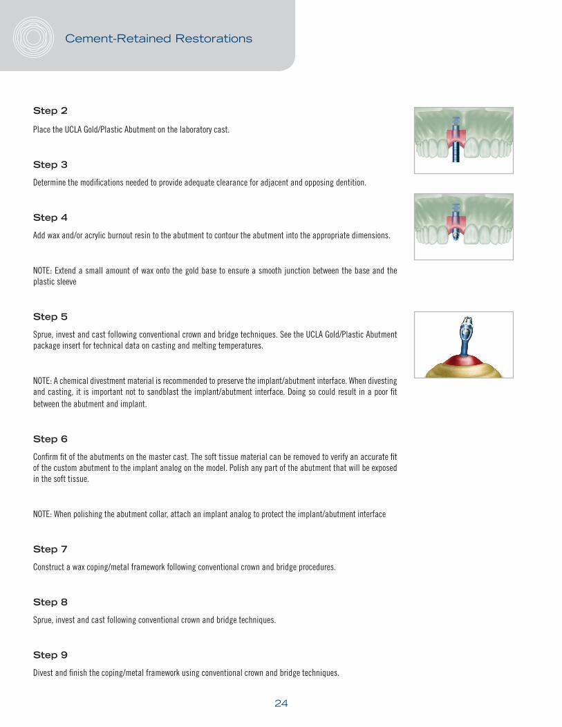
Place the UCLA Gold/Plastic Abutment on the laboratory cast.
Step 3
Determine the modifications needed to provide adequate clearance for adjacent and opposing dentition.
Step 4
Add wax and/or acrylic burnout resin to the abutment to contour the abutment into the appropriate dimensions.
NOTE: Extend a small amount of wax onto the gold base to ensure a smooth junction between the base and the plastic sleeve
Step 5
Sprue, invest and cast following conventional crown and bridge techniques. See the UCLA Gold/Plastic Abutment package insert for technical data on casting and melting temperatures.
NOTE: A chemical divestment material is recommended to preserve the implant/abutment interface. When divesting and casting, it is important not to sandblast the implant/abutment interface. Doing so could result in a poor fit between the abutment and implant.
Step 6
Confirm fit of the abutments on the master cast. The soft tissue material can be removed to verify an accurate fit of the custom abutment to the implant analog on the model. Polish any part of the abutment that will be exposed in the soft tissue.
NOTE: When polishing the abutment collar, attach an implant analog to protect the implant/abutment interface
Step 7
Construct a wax coping/metal framework following conventional crown and bridge procedures.
Step 8
Sprue, invest and cast following conventional crown and bridge techniques.
Step 9
Divest and finish the coping/metal framework using conventional crown and bridge techniques.
Cement-Retained Restorations

25
NOTE: If requested, the coping/metal framework may now be returned to the dentist for metal try-in.
Step 10
If there is no metal framework try-in, proceed to section Porcelain Application following standard laboratory procedures. Return the final restoration on the master model to the clinician.
CLINICAL SECTION
Metal Framework Try-in
Step 1
Remove the metal framework from the master model. Before placement in the mouth, note the orientation marks on the model and on the UCLA custom abutments placed by the dental technician.
Step 2
Place the UCLA custom abutments in the patient’s mouth. Verify that the position of the orientation mark is towards the buccal.
Step 3
Use the quad driver and the lab abutment screw to hand tighten the abutments in the mouth.
Step 4
Take a radiograph to verify that the abutments are completely seated.
Step 5
Seat the coping/metal framework and verify that the framework fits passively and completely over the UCLA custom abutments.
NOTE: If the framework binds during seating or does not go completely down to the margin of the abutment(s), then the bridge must be sectioned, orientated in the mouth, and returned to the laboratory for soldering/laser welding.
Step 6
Reseat the sections in the mouth and lute the sections of the framework together using a pattern resin material. Once the material has set to the manufacturer’s specifications:
• Return the metal framework to the laboratory to be soldered/laser welded and returned for a second framework fitting.
OR
• Pick up the luted framework in a secondary full arch impression. Return the impression to the laboratory for soldering/laser welding and porcelain application.
Cement-Retained Restorations
26
Step 7
If the metal framework did fit passively and completely, it can be removed along with the UCLA custom abutments and returned to the laboratory.
LABORATORY SECTION
Porcelain Application
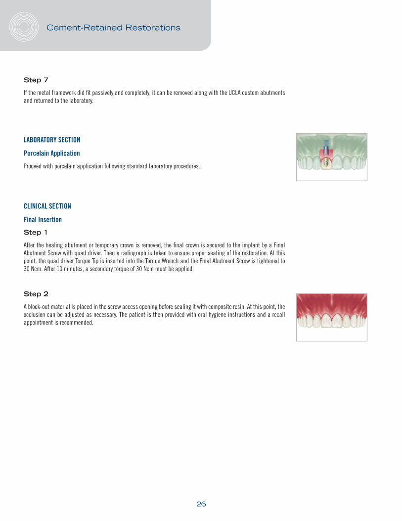
Proceed with porcelain application following standard laboratory procedures.
CLINICAL SECTION
Final Insertion
Step 1
After the healing abutment or temporary crown is removed, the final crown is secured to the implant by a Final Abutment Screw with quad driver. Then a radiograph is taken to ensure proper seating of the restoration. At this point, the quad driver Torque Tip is inserted into the Torque Wrench and the Final Abutment Screw is tightened to 30 Ncm. After 10 minutes, a secondary torque of 30 Ncm must be applied.
Step 2
A block-out material is placed in the screw access opening before sealing it with composite resin. At this point, the occlusion can be adjusted as necessary. The patient is then provided with oral hygiene instructions and a recall appointment is recommended.
Cement-Retained Restorations

27
Quick-Abutment System
The Quick-Abutment System is a pre-tapered abutment with an impression cap to take an abutment-level impression which virtually eliminates the need for retraction cord. All necessary components for the restorative and laboratory procedures, including abutment, abutment screw, healing cap, abutment analog and plastic sleeve, are delivered in one convenient box.
Available cuff heights and contours
• Contours 5.0 mm, 6.0 mm, and 7.0 mm.
• Cuff heights of 0.5 mm, 1.5 mm, 2.5 mm, and 4.0 mm.
Technical Considerations
• For use in single-tooth or multi-unit restorations.
• Inter-occlusal space needed is 4.0 mm plus cuff height. Include 2 mm of inter-occlusal space for the restoration.
• Includes an abutment screw. (Torque to 30 Ncm.)
• It is recommended that the Laboratory Screw be used during laboratory procedures to avoid damage to the Final Abutment Screw.
Indication and intended use
• Single, partial and fully edentulous restorations.
• All areas of the mouth.
Quick-Abutment System and tools needed:
Cement-Retained Restorations
Quad DriverSwivel Head
Torque Wrench
Quick-Abutment Plastic Sleeve
Quick-Abutment Analog
Quick-Abutment Temporary/ Healing Cap
Quick-Cap Impression Cap
Quick-Abutment and Screw
Laboratory Screw
Quad DriverTorque Tip

28
CLINICAL SECTION
Abutment Level Impression
Using a periodontal probe, measure the tissue depth on the buccal from the top of the implant platform to the crest of the gingival tissue. Select the appropriate Quick-Abutment. The selection is based on the criteria to place the margin of the crown approximately 1.0 mm below the gum for ideal esthetics.
NOTE: For additional inter-occlusal clearance, the abutment may be modified an additional 1.0 mm. Reduce the height of the abutment to the bottom of the laser mark. You MUST notify the laboratory by noting on the prescription or using the REDUCED by 1.0 mm slip included in the package before the restoration is fabricated. To ensure a perfect fit of the final crown, if the abutment was reduced to the bottom of the laser mark by the clinician, the Quick-Abutment analog will need to be reduced to the bottom of the laser mark by the dental technician.
Step 1
The healing abutment is removed with the quad driver. The Quick-Abutment is also inserted using the quad driver. The Final Abutment Screw is torqued to 30 Ncm. Then a radiograph is taken to ensure proper seating of the abutment. After 10 minutes a secondary torque of 30 Ncm must be applied.
Step 2
The flat and groove of the Quick-Cap Impression Cap is aligned with the flat and groove of the Quick-Abutment. The Quick-Cap Impression Cap is pushed until it snaps, indicating that the cap is fully engaged.
Step 3
A closed tray impression is then taken using a medium or heavy body impression material.
Step 4
Select the corresponding flare and diameter Quick-Abutment analog. Snap the analog into the Quick-Cap Impression Cap and pour the stone model. The Quick-Abutment Temporary/Healing Cap is placed on the Quick-Abutment or a temporary crown is seated.
Cement-Retained Restorations

29
Placement of the Quick-Abutment Temporary/Healing Cap
a. Use as a Healing Cap
If a temporary restoration is not being fabricated, the Quick-Abutment Temporary/Healing Cap can be used to protect the Quick-Abutment while the final restoration is being fabricated. A soft temporary cement is recommended.
NOTE: The Quick-Abutment Temporary/Healing Caps cannot be re-sterilized and are designed for short-term use
b. Use as a Temporary Cap
The Quick-Abutment Temporary/Healing Cap can be used as a foundation for fabrication of temporary restoration. Add acrylic to create a temporary restoration for cementation. The Quick-Abutment Temporary/Healing Cap is manufactured from PMMA (poly [methylmethacrylate]) which will directly bond to most dental office acrylics.
NOTE: Take a post-operative radiograph to verify that no excess cement is in the area of the incision.
NOTE: To accurately finish the margins of the temporary restorations, a Quick-Abutment analog may be used.
LABORATORY SECTION
Laboratory Cast
NOTE: If a PFM restoration is indicated, follow crown and bridge procedures in section Fabrication of the Restoration – Utilizing the Plastic Sleeve. If an all-ceramic restoration is indicated, follow the procedures in the section Fabrication of Restoration – Utilizing the Quick-Abutment Ceramic Coping.
Step 1
Inspect the impression for accuracy. Seat the Quick-Abutment analog in the impression; align the flat and groove of the impression cap to the flat and groove of the abutment analog.
NOTE: If the margins of the restoration are subgingival, a soft tissue model is recommended.
NOTE: Refer to the clinicians’ prescription or if the REDUCED BY 1.0 mm slip is included with the case. This will inform you that the clinician has modified the abutment and you will need to make the necessary modifications to the abutment analog before proceeding with wax-up of the restoration.
Cement-Retained Restorations
30
Fabrication of the Restoration - Utilizing the Plastic Sleeve
There are two types of plastic sleeves:
a. Locking – single unit restorations
b. Non-Locking – multi-unit splinted restorations
Step 1
Select the appropriate prefabricated plastic sleeve for a single or multi-unit cement-retained restoration.
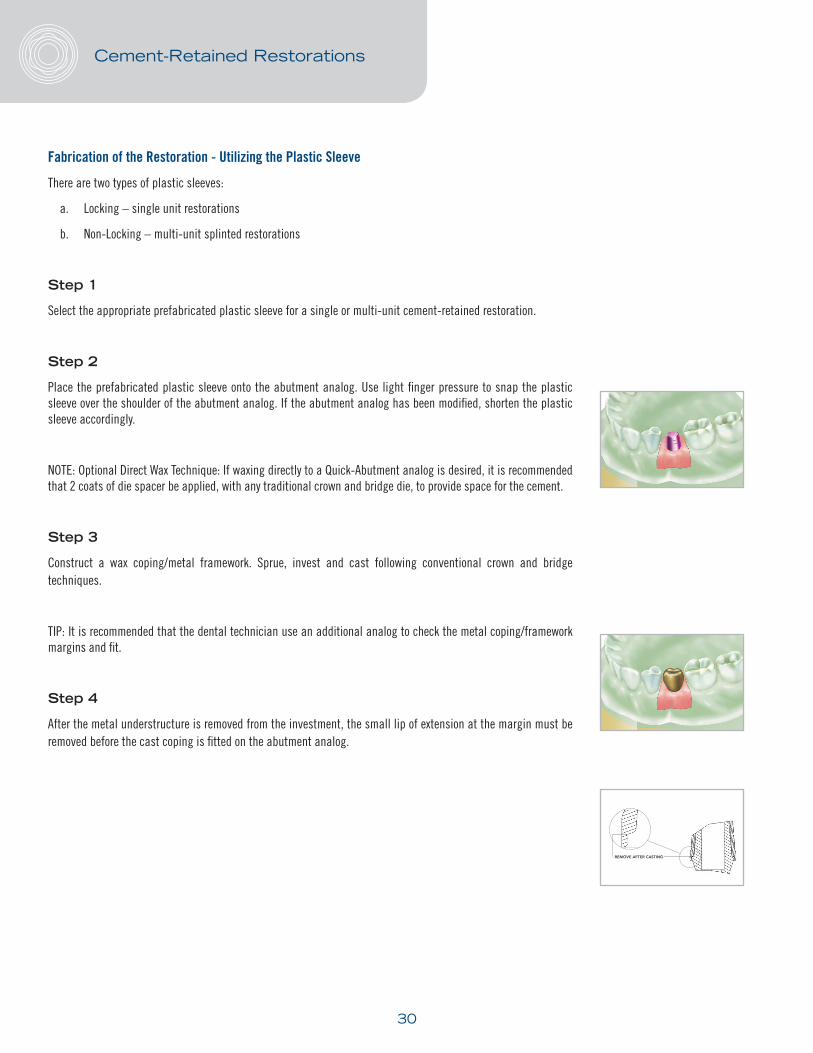
Step 2
Place the prefabricated plastic sleeve onto the abutment analog. Use light finger pressure to snap the plastic sleeve over the shoulder of the abutment analog. If the abutment analog has been modified, shorten the plastic sleeve accordingly.
NOTE: Optional Direct Wax Technique: If waxing directly to a Quick-Abutment analog is desired, it is recommended that 2 coats of die spacer be applied, with any traditional crown and bridge die, to provide space for the cement.
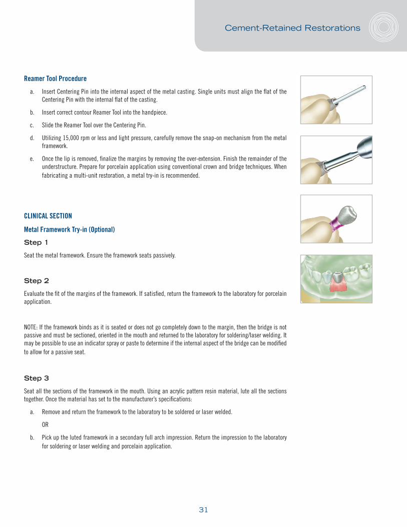
Step 3
Construct a wax coping/metal framework. Sprue, invest and cast following conventional crown and bridge techniques.
TIP: It is recommended that the dental technician use an additional analog to check the metal coping/framework margins and fit.
Step 4
After the metal understructure is removed from the investment, the small lip of extension at the margin must be removed before the cast coping is fitted on the abutment analog.
Cement-Retained Restorations
REMOVE AFTER CASTING
31
Reamer Tool Procedure
a. Insert Centering Pin into the internal aspect of the metal casting. Single units must align the flat of the Centering Pin with the internal flat of the casting.
b. Insert correct contour Reamer Tool into the handpiece.
c. Slide the Reamer Tool over the Centering Pin.
d. Utilizing 15,000 rpm or less and light pressure, carefully remove the snap-on mechanism from the metal framework.
e. Once the lip is removed, finalize the margins by removing the over-extension. Finish the remainder of the understructure. Prepare for porcelain application using conventional crown and bridge techniques. When fabricating a multi-unit restoration, a metal try-in is recommended.
CLINICAL SECTION
Metal Framework Try-in (Optional)
Step 1
Seat the metal framework. Ensure the framework seats passively.
Step 2
Evaluate the fit of the margins of the framework. If satisfied, return the framework to the laboratory for porcelain application.
NOTE: If the framework binds as it is seated or does not go completely down to the margin, then the bridge is not passive and must be sectioned, oriented in the mouth and returned to the laboratory for soldering/laser welding. It may be possible to use an indicator spray or paste to determine if the internal aspect of the bridge can be modified to allow for a passive seat.
Step 3
Seat all the sections of the framework in the mouth. Using an acrylic pattern resin material, lute all the sections together. Once the material has set to the manufacturer’s specifications:
a. Remove and return the framework to the laboratory to be soldered or laser welded.
OR
b. Pick up the luted framework in a secondary full arch impression. Return the impression to the laboratory for soldering or laser welding and porcelain application.
Cement-Retained Restorations

32
LABORATORY SECTION
Porcelain Application
Proceed with porcelain application following conventional laboratory procedures.
CLINICAL SECTION
Final Insertion
Step 1
Remove the Temporary/Healing Cap or temporary crown. Check that all temporary cement is removed from the Quick-Abutment.
Step 2
The crown is placed and occlusion and esthetics are evaluated and adjusted as necessary.
NOTE: It is recommended that the screw access hole be blocked out with a block-out material.
Step 3
The crown is cemented onto the Quick-Abutment. All excess cement must be meticulously removed and the occlusion is evaluated once more. The patient is then provided with oral hygiene instructions and a recall appointment is recommended.
Fabrication of the Restoration - Utilizing the Quick-Abutment Ceramic Coping
LABORATORY SECTION
Step 1
Select the Ceramic Coping that matches the corresponding Quick-Abutment.
Step 2
Reduce/adjust the Ceramic Coping using traditional porcelain fine diamond finishing burs and wheels as needed in order to provide for ideal dimensions for porcelain application. Use irrigation to keep the Ceramic Coping cool during preparation.
Cement-Retained Restorations

33
CONSIDERATIONS:
• Do not reduce the thickness to less than 0.5 mm.
• All edges and angles must remain rounded to prevent porcelain fracture.
• Do not use the Ceramic Coping option if more than 2 mm of porcelain thickness is required.
Step 3
Sandblast the surface of the Ceramic Coping with 50 - 120 micron aluminum oxide at 30 - 38 PSI. Steam clean or use distilled water in an ultrasonic cleaner.
Step 4
Select porcelain which is specifically formulated for Zirconia application. This type of porcelain will accommodate the coefficient of thermal expansion (CTE) of the Ceramic Coping.
Step 5
Apply porcelain and complete the restoration following the manufacturer’s recommendations.
CLINICAL SECTION
Final Insertion
Step 1
Remove the Temporary/Healing Cap or temporary crown. Check that all temporary cement is removed from the Quick-Abutment.
Step 2
The crown is placed and occlusion and esthetics are evaluated and adjusted as necessary.
NOTE: It is recommended that the screw access hole be blocked out with a block-out material.
Step 3
The crown is cemented onto the Quick-Abutment. All excess cement must be meticulously removed and the occlusion is evaluated once more. The patient is then provided with oral hygiene instructions and a recall appointment is recommended
Cement-Retained Restorations

34
Screw-Retained Restorations
UCLA Abutment System
The UCLA Gold/Plastic Abutment is recommended for fabrication of a customized abutment for both screw- and cement-retained restorations, using regular wax-up and cast-to techniques. The Gold/Plastic abutment combines a precision-machined interface with the convenience of a castable plastic sleeve. The plastic sleeve portion is color-coded to match the implant diameter for easy identification.
Intended Applications
• Single, partial and fully edentulous restorations.
• All tooth positions.
• Screw-retained single tooth restorations.
• Bar-retained Overdenture restorations.
• Angle corrections up to 15˚.
Technical Considerations
• A minimal inter-occlusal distance of 4.5 mm is required between the implant prosthetic table and the top of the abutment screw when seated.
UCLA Abutment and tools needed:
LABORATORY SECTION
Laboratory Cast Fabrication
Step 1
Pour the soft tissue material around the implant analog. When the material has set, pour a stone laboratory cast.
Quad DriverSwivel Head
Torque Wrench
Final Abutment Screw
Laboratory Screw
Quad DriverTorque Tip
UCLA Abutment(Locking shown)

35
Metal Framework Fabrication
Step 1
Place the UCLA Gold/Plastic Abutment on the laboratory cast.
Step 2
The plastic sleeve should be reduced to a point where it is slightly out of occlusion. Add wax and/or acrylic resin to the sleeve to contour the abutment into the appropriate dimensions.
Step 3
Sprue, invest and cast following conventional crown and bridge techniques. See the UCLA Gold/Plastic Abutment package insert for technical data on casting and melting temperatures.
Step 4
Confirm fit of the screw-retained framework on the laboratory cast. The soft tissue material can be removed to verify an accurate fit of the framework to the implant analog on the model. Polish any part of the abutment/frame that will be exposed in the soft tissue.
NOTE: A chemical divestment material is recommended to preserve the implant/abutment interface. When divesting and casting, it is important not to sandblast the implant/abutment interface. Doing so could result in a poor fit between the abutment and implant.
NOTE: When polishing the abutment collar, attach an implant analog to protect the implant/abutment interface.
CLINICAL SECTION
Screw-Retained Metal Try-In
Step 1
Place the screw-retained metal restoration in the mouth. Verify the fit between the implant and abutment interface.
If a multi-unit bridge, verify the fit as follows:
a. Place the first laboratory abutment screw with the quad driver and confirm that the bridge is still seating on the remaining implants.
b. Continue placing one screw at a time until all laboratory abutment screws are placed.
c. If the metal framework fits passively and completely, it can be removed and returned to the laboratory. Then replace the healing abutments.
d. If the bridge does not seat passively, section the bridge and reassemble in the mouth.
NOTE: If the framework binds as it is seated or does not go completely down to the implants, then the bridge must be sectioned, orientated in the mouth, and returned to the laboratory for soldering/laser welding.
Screw-Retained Restorations

36
Step 2
Reseat the sections in the mouth and lute the sections of the framework together using a pattern resin material. Once the material has set to the manufacturer’s specifications:
• Return the metal framework to the laboratory to be soldered/laser welded and returned for a second framework try-in.
OR
• Pick up the luted framework in a secondary full arch impression. Then, return the framework to the laboratory for soldering/laser welding and porcelain application.
LABORATORY SECTION
Porcelain Application
Apply an opaque layer to the coping/metal framework. Apply a porcelain application following conventional laboratory procedures. Polish any exposed metal with a gold polishing paste.
CAUTION: Do not sandblast the pre-machined surface of the metal framework.
TIP: When polishing the abutment and the implant collar, attach an implant analog to protect the implant/abutment interface.
CLINICAL SECTION
Final Insertion
Step 1
After the healing abutment or temporary crown is removed, the final crown is secured to the implant by a Final Abutment Screw with quad driver. Then a radiograph is taken to ensure proper seating of the restoration. At this point, the Quad Driver Torque Tip is inserted into the Torque Wrench and the Final Abutment Screw is tightened to 30 Ncm. After 10 minutes, a secondary torque of 30 Ncm must be applied.
Screw-Retained Restorations

37
Step 2
A block-out material is placed in the screw access opening before sealing it with composite resin. At this point, the occlusion can be adjusted as necessary. The patient is then provided with oral hygiene instructions and a recall appointment is recommended.
Screw-Retained Restorations
38
There are two types of Overdenture Abutment Systems available: the LOCATOR® Abutment System and the Snap Abutment System.
LOCATOR Abutment System
LOCATOR Abutments are used with two or more implants as the attachment mechanism between the implants and the patient’s denture for attachment-retained overdenture restorations. The LOCATOR Abutment threads directly into the implant and the Denture Cap is processed into the denture base by either a chairside method or at the dental laboratory. The Nylon Retentive Inserts offer varying degrees of retention to stabilize the denture.
Indications
The LOCATOR Abutment System is designed for use with overdentures or partial dentures retained in whole or in part by implants.
Contraindications
• Use where a totally rigid connection is required.
• Use on two or more implants with greater than 40° total divergence.
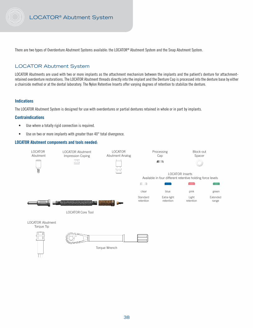
LOCATOR Abutment components and tools needed:
LOCATOR® Abutment System
LOCATOR AbutmentTorque Tip
Torque Wrench
LOCATOR Abutment Analog
LOCATOR Core Tool
LOCATOR Abutment Impression Coping
Processing Cap
LOCATOR Abutment
LOCATOR InsertsAvailable in four different retentive holding force levels
clear blue pink green
Lightretention
Standardretention
Extra-lightretention
Extendedrange
Block-outSpacer

39
How To Use The LOCATOR Tool
The LOCATOR Core Tool is made up of three tools in one:
1. LOCATOR Abutment Driver for tightening of abutment.
2. LOCATOR Insert Seating Tool for seating an insert into a titanium processing cap.
3. LOCATOR Insert Removal Tool for catching and pulling a used insert out of the titanium processing cap.
The sleeve slips onto the driver end of LOCATOR® Core Tool, and is designed to hold a LOCATOR Abutment onto the driver. This allows the driver/sleeve and abutment to be held vertically without the abutment falling off the driver, making it easier to deliver the abutment to the patient’s implant.
Loosen the Male Removal Tool a full 3 turns counter clockwise (you will see a visible gap).
To remove a LOCATOR nylon male from the titanium metal housing, simply insert the tip into the cap/male assembly and push straight in to the bottom of the nylon male. Then tilt the tool so that the sharp edge of the tip will grab hold of the male and pull it out of the cap.
To discard the nylon male from the tip on the Core Tool, point the tool down and away and tighten the Male Removal Tool clockwise back onto the Core Tool. This will activate the removal pin and dislodge the nylon male from the tip end of the Male Removal Tool.
Separate the Male Removal Tool section from the LOCATOR Core Tool and use the Male Seating Tool end of the remaining two sections to place a new nylon male into the empty titanium metal housing.
LOCATOR® Abutment System
Gap
Male Seating Tool End

40
Chairside Placement of the LOCATOR Abutment – New Denture
CLINICAL SECTION
Abutment Selection
Step 1
Measure the tissue thickness from the top of the prosthetic table of the implant to the crest of the gingiva at the highest side of the implant site. Choose the abutment cuff height that equals the tissue measurement, or the next closest higher size available. This will position the functioning 1.5 mm of the abutment above the surrounding gingival level (which should not be submerged below the tissue).
Step 2
Thread the LOCATOR Abutment into the implant using the LOCATOR Abutment Driver or the LOCATOR Torque Wrench Driver and the Conversion Handle. Torque the LOCATOR Abutments to 30 Ncm.
Step 3
Place a LOCATOR Abutment Impression Coping onto each LOCATOR Abutment and press down firmly.
Step 4
Take a full arch impression using a firm body impression material, exercising caution not to compress the soft tissue.
Step 5
Inspect the impression for accuracy. The black inserts should be clearly visible in the impression.
NOTE: If the patient is wearing an existing denture, be sure to relieve the underside of the denture, add a soft liner material over the LOCATOR abutments to prevent excessive loading until the prosthesis is complete.
LABORATORY SECTION
Laboratory Cast Fabrication and Processing
Step 1
Press a LOCATOR Abutment Analog into each Abutment Impression Coping in the impression. Pour the laboratory cast.
Step 2
Fabricate the baseplate and wax rim on the cast for bite registration. The Denture Caps with Black Processing Males may be processed into the baseplate to provide stabilization during occlusal records.
LOCATOR® Abutment System
Step 1

41
CLINICAL SECTION
Step 1
Secure the occlusal rim to the LOCATOR Abutments. Use standard prosthodontic techniques for tooth selection and positioning.
LABORATORY SECTION
Step 1
Follow normal laboratory and clinical procedures for denture wax-up techniques.
CLINICAL SECTION
Step 1
Place the wax denture into the mouth and verify esthetics, phonetics, and occlusion. Make any necessary adjustments.
LABORATORY SECTION
Step 1
Process the denture using normal laboratory procedures. Place a white block-out spacer over the head of each LOCATOR Abutment Analog.
Step 2
Insert the LOCATOR Black Processing Male into each LOCATOR Abutment Analog, leaving the white block-out spacer beneath it.
Step 3
Complete the processing and polishing of the final denture and discard the white spacer. Return the completed denture to the clinician.
LOCATOR® Abutment System

42
CLINICAL SECTION
Step 1
Seat the denture with the Black Processing Male still in place to gauge initial retention. If the retention is acceptable, the Black Processing Male may be worn clinically for a period of time determined by the clinician. This will allow time to make necessary adjustment to the denture if required.
Step 2
When patient is ready for final retention inserts, remove the Black Processing Male using the LOCATOR Core Tool. Place the insert of choice into the housings with the male seating tool.
Step 3
Deliver the final denture in the patient’s mouth, engaging the LOCATOR Abutments. Make necessary adjustments to the occlusion.
Chairside Placement of the LOCATOR® Abutment – Existing Denture
Abutment Selection
Step 1
Measure the tissue thickness from the top of the prosthetic table of the implant to the crest of the gingival at the highest side of the implant site. Choose the abutment cuff height that equals the tissue measurement, or the next closest higher size available. This will position the functioning 1.5 mm of the abutment above the surrounding gingival level (which should not be submerged below the tissue).
Step 2
Thread the LOCATOR Abutment into the implant using the LOCATOR Abutment Driver or the LOCATOR Torque Wrench Driver and the Conversion Handle. Torque the LOCATOR Abutment to 30 Ncm.
Step 3
Place a white block-out spacer over the head of each LOCATOR Abutment.
Step 4
Insert a LOCATOR Cap with Black Processing Male onto each LOCATOR Abutment, leaving it above the white block-out spacer.
LOCATOR® Abutment System

43
Step 5
Use an acrylic laboratory bur to relieve the denture base in the areas where the denture caps are to be placed.
Step 6
On the lingual side of the denture, using a round bur create a vent hole in the denture to allow excess acrylic to flow out of the denture.
Step 7
Use a light-cure acrylic resin to bond the LOCATOR® Denture Cap Male into the denture. Mix some acrylic and fill the recess for the processing male about half-way. Add additional acrylic to the top of the processing male.
Step 8
Insert the denture into position in the mouth. Guide the denture into occlusion while maintaining a proper relationship with the opposing arch.
Step 9
Disengage the denture from the LOCATOR Abutments and remove from the mouth. Verify that the denture caps have been securely picked up in the denture.
Step 10
Remove the Black Processing Male from the metal denture cap. Insert the male removal tool end into the cap male assembly and push straight down into the bottom of the retentive insert.
Step 11
Firmly push a LOCATOR Replacement Male into the metal denture cap using the LOCATOR Core Tool.
Step 12
Deliver the final denture in the patient’s mouth, engaging the LOCATOR Abutments. Make necessary adjustments to the occlusion.
LOCATOR® Abutment System

44
Reline and Rebase a LOCATOR® Case
Step 1
Remove each existing replacement insert from its processing male following the steps in HOW TO USE THE LOCATOR TOOL. Replace them with Black Processing Replacement Males. The built-in spacer of the Black Processing Male will maintain the overdenture in its level of vertical resiliency during the reline process.
Step 2
Using an impression material, take a reline impression using the existing overdenture as a tray. The Black Processing Males will engage the LOCATOR Abutments and hold the prosthesis in place while the impression material sets.
Step 3
When the impression is removed, the Black Processing Males will remain in the metal denture caps.
Step 4
Press down a LOCATOR Abutment Analog into each Black Processing Male and pour a master cast.
Step 5
After processing the reline and polishing the denture base, replace the Black Processing Males with the final retentive inserts.
LOCATOR® Abutment System

45
Snap Abutment System
The Snap Abutment System is for an Attachment-Retained Overdenture restoration where the patient is fully edentulous.
Indications
The Snap Abutment System is designed for use with overdentures.
Contraindications
• Totally rigid connections.
• Use on two or more implants with greater than 20° total divergence.
• If a patient cannot tolerate pressure on the mucosa, this type of restoration is not an option.
Technical Considerations
• A minimum inter-occlusal clearance of 7.0 mm + cuff height is required.
• The patient must have good manual dexterity to align the denture directly over the attachments prior to seating.
Snap Abutment components and tools needed:
Chairside Placement of the Snap Abutment – New Denture
CLINICAL SECTION
Abutment Selection
Step 1
Measure the tissue thickness from the top of the prosthetic table of the implant to the crest of the gingiva at the highest side of the implant site. Choose an abutment cuff height that is 1.0 mm higher than the measured tissue or the next closest higher size available. This will position the functioning 1.0 mm of the abutment above the surrounding gingival level (which should not be submerged below the tissue).
Snap Abutment System
Snap Abutment Snap AbutmentAnalog
Snap Abutment Retentive InsertsLow Medium High
Snap AbutmentHousing
Snap AbutmentTorque Tip
Torque Wrench

46
Step 2
Thread the Snap Abutment into the implant using the Overdenture Abutment Driver or the Overdenture Torque Tip and the Conversion Handle. Torque the Snap Abutment to 30 Ncm.
Step 3
Take a full arch impression using a firm body impression material, exercising caution not to compress the soft tissue. Impression the top of the Snap Abutment and include capturing the hex below the Snap Abutment. This will provide a positive seat for the Snap Abutment analog placement by the laboratory.
Step 4
Inspect the impression for accuracy. Inspect if the hex below the Snap Abutment has been captured.
NOTE: If the patient is wearing an existing denture and until the prosthesis is complete, be sure to relieve the underside of the denture and add a soft liner material over the Snap Abutments to prevent excessive loading.
LABORATORY SECTION
Laboratory Cast Fabrication and Processing
Step 1
Press the Snap Abutment analog into the impression. Completely seat the analog engaging the hex portion of the analog. The Snap Abutment analog must not dislodge during vibration of the stone.
Step 2
Fabricate the baseplate and wax rim on the cast for the bite registration. The denture caps are incorporated into the baseplate to provide stabilization during occlusal records.
CLINICAL SECTION
Step 1
Secure the occlusal rim assembly to the Snap Abutments. Use standard prosthodontic techniques for tooth selection and positioning.
Snap Abutment System

47
LABORATORY SECTION
Step 1
Follow normal laboratory and clinical procedures for denture wax-up techniques.
CLINICAL SECTION
Step 1
Place the wax denture into the mouth and verify esthetics, phonetics, and occlusion. Make any necessary adjustments.
LABORATORY SECTION
Step 1
Process the denture using normal laboratory procedures. Place the metal spacer over the head of each Snap Abutment analog.
Step 2
Insert the Snap Abutment metal housing and red insert onto each Snap Abutment analog, leaving the metal block-out spacer beneath it.
Step 3
Complete the processing and polishing of the final denture and discard the gold spacer. Return the completed denture to the clinician.
CLINICAL SECTION
Step 1
Seat the denture with the red insert still in place to gauge initial retention. If the retention is acceptable, the metal housing and red insert may be worn clinically for a period of time determined by the clinician. This will allow time to make any necessary adjustment to the denture, if required.
Step 2
When patient is ready for final retention, remove the red insert using the Snap Retention Insert Seating Tool and place the insert of choice into the housings.
Step 3
Deliver the final denture in the patient’s mouth, engaging the Snap Abutments. Make necessary adjustments to the occlusion.
Snap Abutment System

48
Chairside Placement of the Snap Abutment – Existing Denture
Abutment Selection
Step 1
To select the proper Snap Abutment, determine the diameter of the implant. Measure the tissue thickness from the top of the prosthetic table of the implant to the crest of the gingiva at the highest side of the implant site. Choose the abutment cuff height that is 1.0 mm higher than the measured tissue or the next closest higher size available.
Step 2
Thread the Snap Abutment into the implant using the Overdenture Abutment Driver or the Overdenture Torque Tip and the Conversion Handle. Torque the Snap Abutment to 30 Ncm.
Step 3
Place a metal spacer over the head of each Snap Abutment which is used to block out the area immediately surrounding the abutment.
Step 4
Insert Snap Abutment housing with a red insert onto each Snap Abutment, leaving the metal spacer beneath it.
Step 5
Use an acrylic laboratory bur to relieve the denture base in the areas where the metal housings will contact the denture.
Step 6
On the lingual side of the denture, using a round bur create a vent hole in the denture to allow excess acrylic to flow out of the denture.
Step 7
Use a light-cured acrylic resin to bond the Snap Abutment housing into the denture. Mix some acrylic and fill the recess for the denture cap about half-way. Add additional acrylic to the top of the Snap Abutment housing.
Step 8
Insert the denture into position in the mouth. Guide the denture into occlusion, maintaining a proper relationship with the opposing arch.
Snap Abutment System
49
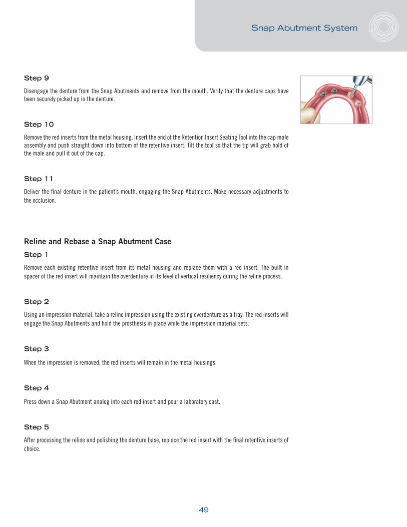
Step 9
Disengage the denture from the Snap Abutments and remove from the mouth. Verify that the denture caps have been securely picked up in the denture.
Step 10
Remove the red inserts from the metal housing. Insert the end of the Retention Insert Seating Tool into the cap male assembly and push straight down into bottom of the retentive insert. Tilt the tool so that the tip will grab hold of the male and pull it out of the cap.
Step 11
Deliver the final denture in the patient’s mouth, engaging the Snap Abutments. Make necessary adjustments to the occlusion.
Reline and Rebase a Snap Abutment Case
Step 1
Remove each existing retentive insert from its metal housing and replace them with a red insert. The built-in spacer of the red insert will maintain the overdenture in its level of vertical resiliency during the reline process.
Step 2
Using an impression material, take a reline impression using the existing overdenture as a tray. The red inserts will engage the Snap Abutments and hold the prosthesis in place while the impression material sets.
Step 3
When the impression is removed, the red inserts will remain in the metal housings.
Step 4
Press down a Snap Abutment analog into each red insert and pour a laboratory cast.
Step 5
After processing the reline and polishing the denture base, replace the red insert with the final retentive inserts of choice.
Snap Abutment System

50
For a Bar Attachment-Retained Overdenture: the UCLA Gold/Plastic Abutment System is available.
When the tissue depth exceeds 3.0 mm, a transmucosal abutment is recommended to extend the seating platform of the restoration to the abutment approximately 1.0 mm to 1.5 mm above the tissue height.
Bar Overdenture Restorations Using the UCLA Gold/Plastic Abutment System
Technical Considerations
A minimal inter-occlusal clearance of 4.5 mm for all diameters of the UCLA Gold/Plastic Abutments is required between the implant prosthetic table and the top of the abutment screw when seated.
LABORATORY SECTION
Laboratory Cast Fabrication
Step 1
Pour the soft tissue around the implant analog and pour a stone laboratory cast.
Wax Rim Fabrication
For the laboratory procedures of a wax bite rim fabrication, follow conventional denture procedures.
NOTE: Since distortion in materials may occur and cause inaccuracies in the impression, a verification jig should be made for all bar restorations. This will ensure an accurate impression was obtained
Verification Jig Fabrication
Step 1
Place the impression posts onto the master cast and hand tighten using the long screws.
Step 2
Intertwine dental floss around the impression posts.
Bar Attachment-Retained Overdentures

51
Step 3
Apply a pattern resin or a light-cured material to the impression posts. Incorporate the dental floss and lute the impression posts together.
Step 4
Section the pattern resin between the impression posts. Mark the impression posts for mid-facial orientation and return to the clinician individually or luted together in sections.
Step 5
Send the sectioned verification jig with the laboratory screws to the clinician for try-in. A passive fit intraorally will confirm that an accurate final impression has been achieved.
CLINICAL SECTION
Inter-occlusal Record and Verification Jig Protocol
Step 1
Seat the occlusal rim. Use standard prosthodontic techniques for tooth selection and positioning.
Step 2
Place the verification jig onto the implants and tighten the screws firmly.
Step 3
Using a pattern resin or a light-cured material, lute the sections together creating a solid verification jig.
Step 4
Once the luted material has set, remove the screws. Lift the luted verification jig from the mouth. There should be no binding or fracturing of the verification jig upon removal.
Bar Attachment-Retained Overdentures
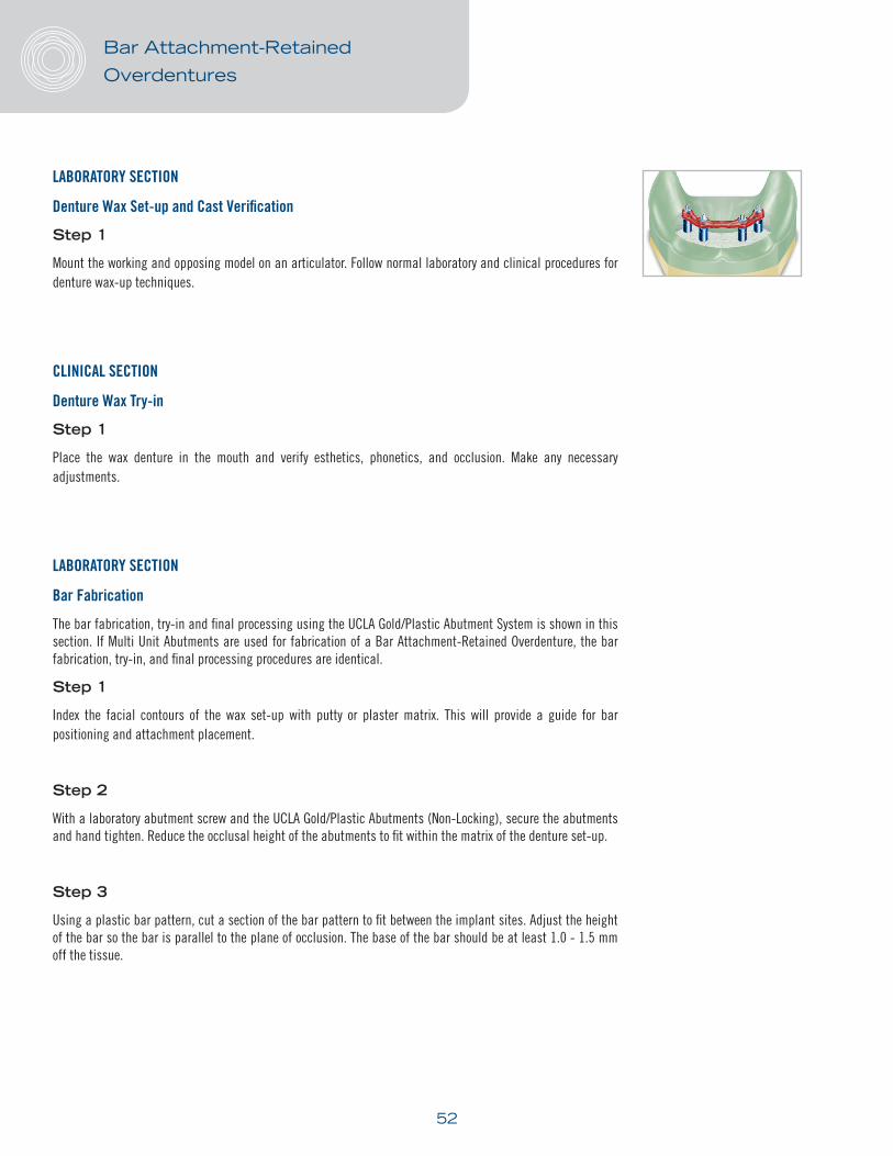
52
LABORATORY SECTION
Denture Wax Set-up and Cast Verification
Step 1
Mount the working and opposing model on an articulator. Follow normal laboratory and clinical procedures for denture wax-up techniques.
CLINICAL SECTION
Denture Wax Try-in
Step 1
Place the wax denture in the mouth and verify esthetics, phonetics, and occlusion. Make any necessary adjustments.
LABORATORY SECTION
Bar Fabrication
The bar fabrication, try-in and final processing using the UCLA Gold/Plastic Abutment System is shown in this section. If Multi Unit Abutments are used for fabrication of a Bar Attachment-Retained Overdenture, the bar fabrication, try-in, and final processing procedures are identical.
Step 1
Index the facial contours of the wax set-up with putty or plaster matrix. This will provide a guide for bar positioning and attachment placement.
Step 2
With a laboratory abutment screw and the UCLA Gold/Plastic Abutments (Non-Locking), secure the abutments and hand tighten. Reduce the occlusal height of the abutments to fit within the matrix of the denture set-up.
Step 3
Using a plastic bar pattern, cut a section of the bar pattern to fit between the implant sites. Adjust the height of the bar so the bar is parallel to the plane of occlusion. The base of the bar should be at least 1.0 - 1.5 mm off the tissue.
Bar Attachment-Retained Overdentures

53
Step 4
Place the matrix back on the model. Use it as a guide to provide adequate clearance for the attachments, housings, bar pattern, teeth and acrylic.
Step 5
Connect the bar pattern to the Gold/Plastic Abutments using wax or resin material.
Step 6
Sprue, invest and cast following conventional crown and bridge techniques.
Step 7
When divesting the bar framework, use of a chemical divesting medium to maintain the integrity of the gold cylinder is recommended.
CAUTION: When polishing the interface between the implant and the prosthetic connection, attach an implant analog to protect the abutment.
CLINICAL SECTION
Bar Framework Try-in
Step 1
Place the bar framework on the implants without any screws and confirm that the bar framework seats passively.
Step 2
Beginning with the most distal implant, place the first laboratory screw. Make sure the abutment interface is completely seated on all the remaining implants.
Step 3
Continue placing one laboratory screw at a time around the arch. Verify the fit of each abutment interface is completely seated on the implant.
Step 4
Once the bar framework is completely seated, follow the conventional procedures for wax set-up evaluation. Evaluate esthetics, phonetics, and occlusion. Make any necessary adjustments.
NOTE: If bar is not passive follow steps below in Sectioning Bar Framework
NOTE: A non-passive fitting bar framework can sometimes cause the patient to feel pressure or a pulling sensation when the abutment screws are tightened.
Bar Attachment-Retained Overdentures
54
Sectioning Bar Framework
Step 1
Make a mark on the bar framework directly after the last fully seated abutment with a laboratory screw and where the bar has lifted.
Step 2
Replace bar on working model and section the framework where necessary with an ultra-thin separating disk and a high-speed handpiece, creating a space of approximately 0.3 mm.
Step 3
Reseat the sections in the mouth, align the sections and lute the sections of the framework together using a pattern resin material.
Step 4
Return the luted bar framework, laboratory screws and abutments to the laboratory for solder/laser welding.
LABORATORY SECTION
Processing Bar and Denture
Step 1
Process the denture using conventional techniques. Return to the clinician for final insertion.
CLINICAL SECTION
Step 1
Insert the bar framework, hand tighten the abutment screws and verify fit. Then, use a Torque Wrench and the quad driver Torque Tip to torque the screws to 30 Ncm. It is recommended to torque the abutment screw, wait 10 minutes, and then torque again to 30 Ncm.
Step 2
Seat the final overdenture and follow conventional procedures for the delivery of the final restoration.
Bar Attachment-Retained Overdentures

©2016 Keystone Dental, Inc.
100039-EN01 Rev B 07/2016
Keystone Dental, Inc. Global Headquarters154 Middlesex TurnpikeBurlington, MA 01803 USAGeneral Inquiries: 781-328-3600Customer Relations: 866-902-9272 or 781-328-3490 Fax: 866-903-9272 or 781-328-3400Email: [email protected]
Keystone Dental SpAEuropean Headquartersvia A. Fleming, 1937135 Verona, ItalyPhone: +39 045 8230294Fax: +39 045 8250296Email: [email protected]
Caution, consult accompanying documents
Trademark AcknowledgementsTiLobe, PrimaConnex, Quick-Cap and “Smarter Thinking. Simpler Design.” are trademarks and registered trademarks of Keystone Dental, Inc.
0086
Keystone Dental, Inc. 5 Holland, Building 209Irvine, CA 92618 USA