tia tsb102.baad 1994
DESCRIPTION
.TRANSCRIPT
~ ~~~
EIA TSBL02.BAAD 9 4 3234600 0556826 5 T 7
I TIAIEIA TELECOMMSJNI CATIONS SYSTEMS BULLETIN APCO Project 25 I Common Air Interface Operational
TSB 102 .BAAD
OCTOBER 1994
TELECOMMUNICATIONS INDUSTRY ASSOCIATION I I INDUSTRY ASSOCIATION
Provided by IHS under license with TIA No reproduction or networking permitted without license from IHS
--``,`,,,```,,`,``,```,`,``,`,,,-`-`,,`,,`,`,,`---

~- ~
E I A TSBL02.BAAD 7 4 m 3234600 0556827 433
NOTICE
TIA/EIA Engineering Standards and Publications are designed to serve the public interest through eliminating misunderstandings between manufacturers and purchasers, facilitating interchangeability and improvement of products, and assisting the purchaser in selecting and obtaining with minimum delay the proper product for his particular need. Existence of such Standards and Publications shall not in any respect preclude any member or nonmember of TIA/EIA from manufacturing or selling products not conforming to such Standards and Publications, nor shall the existence of such Standards and Publications preclude their voluntary use by those other than TIA/EIA members, whether the standard is to be used either domestically or internationally.
Recommended Standards, fibfiations and Bulletins are adopted by TIA/EIA in accordance with the American National Standards Institute (ANSI) patent policy. By such action, TINEIA does not assume any liability to any patent owner, nor does it assume any obligation whatever to parties adopting the Recommended Standard, Publication or Bulletin.
Technical Bulletins are distinguished from TINETA Recommended Standards or Interim Standards, in that they contain a compilation of engineering data or information useful to the technical community, and represent approaches to good engineering practices that are suggested by the formulating committee.
This Bulletin is not intended to preclude or discourage other approaches that similarly represent good engineering practice, or that may be acceptable to, or have been accepted by, appropriate bodies. Parties who wish to bring other approaches to the attention of the formulating committee to be considered for inclusion in future revisions of this Bulletin are encouraged to do so. It is the intention of the formulating committee to revise and update this Bulletin from time to time as may be occasioned by changes in technology, industry practice, or government regulations, or for other appropriate reasons.
Published by
@I’EL,ECOMMUNICATIONS INDUSTRY ASSOCIATION 1994 Standards and Technology Department
2001 Pennsylvania Ave. N. W, , Washington, D.C. 20006
PRICE: Please refer to the current Catalog of EIA, JEDEC and TIA STANDARDS and ENGINEERING PUBLICATIONS
or caii Global Engineering Documents, USA and Canada (1-800-854-7179) International (303-397-7956)
All rights reserved Printed in U.S.A.
Provided by IHS under license with TIA No reproduction or networking permitted without license from IHS
--``,`,,,```,,`,``,```,`,``,`,,,-`-`,,`,,`,`,,`---

PLEASE!
DON'T VIOLATE THE LAW!
This document is copyrighted by the TIA and may not be reproduced without permission.
Organizations may obtain permission to reproduce a limited number of copies through entering into a license agreement with the EM.
Interested organizations should contact:
EIA Standard Sales Office 2001 Pennsylvania Ave., N.W. Washington, D.C. 20006
(202)457-4966
Requesting a copy of the agreement.
Provided by IHS under license with TIA No reproduction or networking permitted without license from IHS
--``,`,,,```,,`,``,```,`,``,`,,,-`-`,,`,,`,`,,`---

TSB 102.BAAD
Foreword
This foreword is not part of this document.
This Telecommunications Systems Bulletin. (TSB) is being promulgated and will be maintained by the TR-8.15 Common Air Interface Subcommittee as part of the effort of TR-8 Private Radio Technical Standards committee under the sponsorship of the Telecommunications Industry Association.
While not finished, TR-8.15 believes that an urgent need exists for and that this document accurately portrays a significant amount of technical information regarding emerging digital technologies for the Land Mobile Service, especially APCO/NASTD/FED Project 25. Therefore TR-8 has chosen to recommend it for publication as a TSB and thereby expedite its expected benefits to the industry.
Generally, the Project 25 Common Air Interface Operational Description for Conventional Channels and various elements thereof have been developed by TIA TR-8.15 to be consistent with the Statement of Requirements adopted by the Project 25 Steering committee. This Standards family includes and borrows heavily from the combined work of various industry and government agency representatives organized under the TIA Project 25 Ad Hoc Interface Committee.
This document presumes that APCO/NASTD/FED will establish an overall Project 25 System standard or specification. It further presumes that TIA will set standards based upon the APCO/NASTD/FED Project 25 standards or specifications.
This TSB provides the Common Air Interface Operational Description as a supplement to the APCO Project 25 Recommended Common Air Interface which is one of the interfaces to be defined under the Project 25 system. While all reasonable efforts have been made to ensure the accuracy of this document, it should be understood that significant work remains in fully developing the Project 25 family of standards and that this document will be updated as necessary to ensure an accurate representation of Project 25 systems as other implementation requirements become available.
The reader's attention is called to the possibility that compliance with the APCO/NASTD/FED Project 25 Standard or any TIA standard for equipment conforming to the APCO/NASTD/FED Project 25 Standard may require the use of one or more inventions covered by patent rights. By publication of those standards, if any, no position is taken with respect to the validity of those claims or any patent rights in connection therewith. The patent holders so far identified have, however filed statements of willingness to grant licenses under those rights on reasonable and nondiscriminatory terms and conditions to applicants desiring to obtain such licenses. Details may be obtained from the publisher.
I
Provided by IHS under license with TIA No reproduction or networking permitted without license from IHS
--``,`,,,```,,`,``,```,`,``,`,,,-`-`,,`,,`,`,,`---

EIA TSBL02.BAAD 74 W 3234600 0556830 T28 = TSB 102.BAAD
This page intentionally left blank.
II
Provided by IHS under license with TIA No reproduction or networking permitted without license from IHS
--``,`,,,```,,`,``,```,`,``,`,,,-`-`,,`,,`,`,,`---

EIA TSBLOZ.BAAD 9 4 U 3234600 0556833 9 6 4
TSB 102.BAAD
Table of Contents
. ............................................. ..................................................... 1 Introduction : 1
1.3 References ................................ ....................................................... 3
3 . Repeater Addressing .................................................................................... 5 4 . Status Symbols ............................................................................................. 6
1.1 Scope ............................................................................................... 1 1.2 Revision History ............................................................................... 3
2 . Unit Addressing ............................................................................................. 3
5 . Voice Transmit Operation ............................................................................. 7 6 . Voice Receive Operation .............................................................................. 10 7 . Repeater Operation ....................................................................................... 12 8. Packet Data Transmit Operation ................................................................... 14
MR Channel Access Procedure ....................................................... 15 8.2 Sequence Numbering ....................................................................... 17 8.3 Resynchronization of Sequence Numbers ....................................... 18
8.5 Procedure to Send a Confirmed Delivery Packet ............................. 19 9 . Packet Data Receive Operation .................................................................... 22
9.1 Procedure for Receipt of a Confirmed Data Packet ......................... 22
8.1
8.4 Fragments ........................................................................................ 18
... III
Provided by IHS under license with TIA No reproduction or networking permitted without license from IHS
--``,`,,,```,,`,``,```,`,``,`,,,-`-`,,`,,`,`,,`---

E I A T S B L 0 2 . B A A D 9 4 W 3234600 0556832 B T O W
TSB 102.BAAD
List of Figures
Figure 1-1 Conventional System Diagrams ...................................................... 2
Figure 3-2 Co-Channel User Examples ............................................................ 5
Figure 7-1 Repeater Configurations .................................................................. 12
Figure 7-3 Assertion of a Status Symbol .......................................................... 13 Figure 8-1 Data System with Asymmetrical Addressing ................................... 14 Figure 8-2 Channel Access State Diagram ....................................................... 15 Figure 8-3 Context of Sequence Numbers V(S). V(R). and N(S) ..................... 17 Figure 8-4 Confirmed Delivery Packet Transmission State Diagram ................ 19 Figure 9-1 Confirmed Delivery Packet Reception State Diagram ..................... 22
Figure 2-1 Example of Unit and Talk Group Addresses ................................... 3 Figure 3-1 Separated Repeaters Servicing a Wide Area .................................. 5
Figure 4-1 Channel Status Example ................................................................. 6
Figure 7-2 Slotted Status Symbols ................................................................... 13
iv
Provided by IHS under license with TIA No reproduction or networking permitted without license from IHS
--``,`,,,```,,`,``,```,`,``,`,,,-`-`,,`,,`,`,,`---

E I A TSBL02.BAAD 74 3234600 0556833 737 = TSB 102.BAAD
List of Tables
Table 5-1 Encrypted Voice Message Conditions .............................................. 9 Table 6-1 Receiver Unmute Conditions ............................................................ 11 Table 8-1 Channel Access Procedure Parameters ........................................... 17 Table 8-2 Meaningful Class, Type and Status in Response ............................. 21 Table 8-3 Response Disposition ....................................................................... 21
V
Provided by IHS under license with TIA No reproduction or networking permitted without license from IHS
--``,`,,,```,,`,``,```,`,``,`,,,-`-`,,`,,`,`,,`---

EIA T S B L 0 2 = B A A D 9 4 E 3234600 0556834 673
TSB 102.BAAD
Terminology
ACK Acknowledgment response for delivery confirmation of a data packet ARQ Automatic Retry Request to retry corrupted data packets BR Base Radio, a reference designating a base station CRC Cyclic Redundancy Checksum to detect errors in data CRC-9 9-bit CRC used in each block of a confirmed data packet FMF Full Message Flag indicates the first copy of a data packet FSSP Frame Sync Seek Period, time allowed to detect a frame sync IMBE Improved Multi-Band Excitation, the voice coder for the Common Air Int. LC Link Control, a code word embedded in a voice message LDU Logical Link Data Unit. There are two different LDUs for voice. MFID Manufacturer's Identifier, to mark message with non-standard formats MR Mobile Radio, a reference designating a mobile or portable radio NAC Network Access Code encoded into a message to mute interference NID Network ID code word, includes the NAC information OS1 Open Systems Interface, a standard communication system definition PTT Push-To-Talk switch, activated for radio to transmit voice RFC Radio Frequency Controller, to control a base station RFG Radio Frequency Gateway, a device to port data into a radio system SAP Service Access Point identifier, an address for a service using data TGID Talk Group Identifier, to identify a talk group in a voice call
vi Provided by IHS under license with TIA No reproduction or networking permitted without license from IHS
--``,`,,,```,,`,``,```,`,``,`,,,-`-`,,`,,`,`,,`---

EIA T S B L 0 2 . B A A D 9 4 I 3 2 3 4 b 0 0 0556835 S O T
TSB 102.BAAD
1. Introduction
This supplement to the Common Air interface [reference 11 describes some simple operational procedures for conventional systems using voice or data. These operational procedures are sufficient for basic operation of conventional radio systems. They are not intended to describe operation of trunked systems or data systems, both of which have additional operating procedures defined elsewhere. This is intended to be interpreted with the Common Air Interface and is not intended to be understood by itself.
The basic procedures defined in this document include those for transmitting and receiving digital voice on a radio channel, and those for transmitting and receiving data packets on a radio channel. The procedures for voice are contained in Sections 5 and 6, while the procedures for data are contained in Sections 8 and 9. The formats for these messages are defined in reference 1, and this document defines simple procedures for their use.
In order to describe the transmission of voice or data, it is necessary to define some simple addressing concepts for subscriber radios and radio repeaters, and also to define simple operating procedures for repeaters. These topics are covered in Sections 2, 3, 4, and 7.
1.1 Scope
This supplement defines sample operational procedures for basic conventional radio systems. A conventional radio system is one that does not include any controlling entity in the infrastructure to assign radio channels. It is different from a trunking system which includes some means of assigning radios to channels, ¡.e. a trunking controller. The sample operational procedures defined in this supplement are, in the whole, not mandatory requirements. However, some of the procedures are mandatory for this supplement, and others may be specified as mandatory for other portions of the APCO-25 set of standards even though they are not specified as mandatory here.
A basic conventional radio system is one which meets the minimum requirements for this supplement. Additional functions or features may be added to a basic system as they are required. The operation of these additional functions is not discussed in this supplement, but it is expected that they will be compatible with the basic operation as described here. Basic procedures covered in this supplement are further restricted to the lower 2 OS1 layers of the radio system. Operation of the encryption function, vocoder function, or user data applications is not explicitly defined here. Operation of trunking control is also not included.
There are several different types of conventional radio system, depending on whether or not a repeater is used. These are diagrammed Figure 1-1.
For the purposes of this document, basic conventional systems can be classed as either repeater systems or direct systems. Repeater systems make use of a full duplex base station that is configured so that all of the signals that are
1 Provided by IHS under license with TIA No reproduction or networking permitted without license from IHS
--``,`,,,```,,`,``,```,`,``,`,,,-`-`,,`,,`,`,,`---

EIA T S B L 0 2 . B A A D 94 3234600 0 5 5 6 8 3 6 4 4 6
TSB 102.BAAD
received are re-transmitted. Direct systems simply transmit directly from one unit to another without the assistance of any intervening repeater. Radio units in a system consist of mobile or portable units, and base stations. The mobile or portable units are represented as MR elements. The base station is represented as a BR element in Figure 1-1. The communication paths are represented as arrows. They are intended to show a simplex (i.e..one direction only) path. Generally, the radios may be capable of operating half duplex, which is to say that they can transmit or receive, but not both at the same time. The repeater is always full duplex. Full duplex operation for portables or mobiles is not discussed for a basic conventional system.
Direct Transmission Repeated Transmission
Figure 1-1 Conventional System Diagrams
Addressing for the mobiles, portables, and base stations is covered in Sections 2 and 3. Section 2 contains some mandatory requirements. Mobile, portables, and base stations also generate Status Symbols, and this subject is covered in Section 4 with some mandatory requirements.
From the stand point of the originating unit, the message is broadcast to all other radio units that are within range of the signal. Those units that are within range may choose to unmute and listen to the signal, or remain muted. The procedures for the originating unit and destination units are covered in Sections 5, 6, 8, and 9. Sections 5, 8, and 9 contain some mandatory requirements. For the purposes of direct systems, either an MR or a BR can be the origination or destination unit. Three representative cases are given in Figure 1-1. Multiple arrows from the originating unit are intended to show communication paths to multiple destination units, of which only a single destination unit is shown.
For repeater systems, the base station is the repeater, and mobile / portable units are the origination and destination units. Multiple destination units can listen to the repeater transmission, but only the repeater is configured to listen to the originating unit. The operation of the repeater is a special case of operation of the units in direct mode, and some aspects of its operation are defined in Sections 2 and 7, with both sections containing mandatory requirements.
The procedures for data transmission and reception are given in Sections 8 and 9. Portions of the procedures are mandatory for interoperability with the Common Air Interface, and these portions are indicated in those sections.
2 Provided by IHS under license with TIA No reproduction or networking permitted without license from IHS
--``,`,,,```,,`,``,```,`,``,`,,,-`-`,,`,,`,`,,`---

E I A TSBL02.BAAD e14 E 3234600 0556837 382
TSB 102.BAAD
1.2 Revision History
February 8, 1993, P25.930208.1 .O, contained basic operating procedures. April 8, 1993, P25.930208.1.1, revised so that it is no longer an appendix. September 17, 1993, P25.930208.1.2, revised to include data operation. November 1 O, 1993, P25.930208.1.3, revised data operation and scope. December 13, 1993, P25.930208.1.4, revised to indicate normative sections.
1.3 References
The following documents are referred to by this document. The versions and dates in these references are the latest available on the date of this document.
1. APCO Project 25 Recommended Common Air Interface, April 1994,
2. APCO Project 25 DES Encryption Protocol, April 1994, IS 102.AAAA. 3. APCO Project 25 Vocoder Description, July 1993, IS 102.BABA.
TSB 102.BAAA.
2. Unit Addressing
A basic conventional radio system consists of a set of radio units and / or repeaters which can communicate with each other. Those radio units which can terminate voice or data messages in the system will be called subscriber units in the system. This definition of subscribers will exclude repeaters for the purposes of basic conventional systems. Subscriber units can be addressed with a 24 bit unit address or with a 16-bit talk group address. A system containing five
j
~~ $000002
I
, , I
, i
subscribers is shown in the Figure 2-1.
i ' (u
1 0 50
p-@ $00001 o
:I- I I I
$0001 02 ,
Talk Group $0001 i kalk Group $0003) ",,,,,,,,,8,88,,,,88,,8,,/,,,,,,8,,8,,8,,~
Figure 2-1 Example of Unit and Talk Group Addresses
In the example of Figure 2-1 every subscriber unit is a member of one or more talk groups. The talk group addresses are represented as 4-digit hexadecimal numbers. Each subscriber has a unit address which is represented as a 6 digit hexadecimal number in the figure. The special talk group address $FFFF contains all of the system units. The other talk groups each contain a subset of
3 Provided by IHS under license with TIA No reproduction or networking permitted without license from IHS
--``,`,,,```,,`,``,```,`,``,`,,,-`-`,,`,,`,`,,`---

EIA TSBLOZ.BAAD 7 4 W 3234b00 0556838 219 = TSB 102.BAAD
the units, that is defined so that communications between members of the talk group is useful and convenient. Any subscriber unit can be a member of any talk group, and any talk group can contain any number of subscriber units.
The address of the unit and talk group may be displayed for use by the radio operators. When the address is displayed, it shall. be displayed with decimal digits O, 1,2, ... 9. The binary value that is transmitted with the Common Air Interface is converted to decimal with standard binary to decimal conversion. Using the hexadecimal equivalents, several example addresses are given below:
hexadecimal decimal display $000 O01 O00 O001 $000 002 O00 0002 $000 003 O00 0003
$000 OOA $000 006
$000 OOF $000 O10
$989 67F
öoo O010 O00 O01 1
O00 0015 O00 0016
999 9999
...
...
The talk group addresses are also converted for display purposes in the same way. The range of talk group addresses normally spans O0001 .. 65534, with decimal value 65535 reserved to signify the group with all units. The talk group O0000 is used to signify a talk group with no members. The talk group O0001 is used as a default for systems which are not explicitly partitioning the system into different talk groups. The default talk group can be programmed into radios at the time of manufacture for convenience.
4 Provided by IHS under license with TIA No reproduction or networking permitted without license from IHS
--``,`,,,```,,`,``,```,`,``,`,,,-`-`,,`,,`,`,,`---

E I A T S R L O Z - B A A D 7 4 I 3234600 0556839 155 = TSB 102.BAAD
3. Repeater Addressing
Repeaters are not considered to be a subscriber unit in basic conventional systems, and consequently do not possess a unit address. They can still be addressed with the Network Access Code in the Common Air Interface. This addressing allows multiple repeaters to occupy the same channel, and remain separate and distinct. The Network Access Code (NAC) allows a large system coverage area to be serviced by separate repeaters, and it also allows multiple repeaters to service multiple systems with overlapping coverage areas. These cases are depicted in figures 3-1 and 3-2.
Figure 3-1 Separated Repeaters Servicing a Wide Area
Figure 3-1 shows three repeaters with each repeater using a different NAC on the inbound path and the same NAC on the outbound path. A subscriber unit may select the NAC based on its proximity to a repeater. For example, within the coverage area of the top repeater, it would use the NAC value $001. The repeater then re-transmits the message with the NAC value $004. The subscriber receivers are programmed to receive the NAC value $004, and in the figure both destination subscribers could receive the message. If the originating unit selected the second repeater, then it might reach a different set of subscribers in a different coverage area. In the figure, only one of the subscribers is reached. The third repeater reaches none of the subscribers shown.
MR NAC $001 NAC $001
‘11 ”I,,, ,,!IlIl”
,,,,1*~‘’ “ i h
p-1-q BR
Co-C han r&~t;:~ïnte ríerence ,,I‘ 0,
MR I NAC$002 Figure 3-2 Co-Channel User Examples
Two examples showing co-channel interference are in figure 3-2. In the situation on the left two repeaters are shown sharing a channel, in this case the outbound channel. The subscribers can be programmed to accept messages with the NAC code specified for their system and reject co-channel interference from the other system. So long as both repeaters do not transmit simultaneously, the users in each system can share the channel. The situation on the right is very similar except that the channel is shared by subscribers operating in the direct mode.
Provided by IHS under license with TIA No reproduction or networking permitted without license from IHS
--``,`,,,```,,`,``,```,`,``,`,,,-`-`,,`,,`,`,,`---
EIA T S B L O Z - B A A D 9 4 m 3234600 0556840 977
TSB 102.BAAD
4. Status Symbols
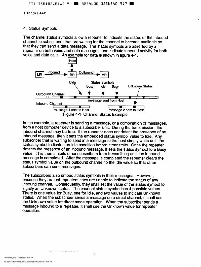
The channel status symbols allow a repeater to indicate the status of the inbound channel to subscribers that are waiting for the channel to become available so that they can send a data message. The status symbols are asserted by a repeater on both voice and data messages, and indicate inbound activity for both voice and data calls. An example for data is shown in figure 4-1.
Data Status Symbols Unknown Status
Outbound I I Channel I 17 II hf I l m I I message sent from Host
Inbound Channel - P message 1 sent to Host message 2 sent to Host
Figure 4-1 Channel Status Example
In the example, a repeater is sending a message, or a combination of messages, from a host computer device to a subscriber unit. During the transmission, the inbound channel may be free. If the repeater does not detect the presence of an inbound message, then it sets the embedded status symbol value to Idle. Any subscriber that is waiting to send in a message to the host simply waits until the status symbol indicates an Idle condition before it transmits. Once the repeater detects the presence of an inbound message, it sets the status symbol to a Busy value. This then inhibits other subscribers from transmitting until the inbound message is completed. After the message is completed the repeater clears the status symbol value on the outbound channel to the Idle value so that other subscribers can send messages.
The subscribers also embed status symbols in their messages. However, because they are not repeaters, they are unable to indicate the status of any inbound channel. Consequently, they shall set the value of the status symbol to signify an Unknown status. The channel status symbol has 4 possible values. There is one value for Busy, one for Idle, and two values to indicate Unknown status. When the subscriber sends a message on a direct channel, it shall use the Unknown value for direct mode operation. When the subscriber sends a message inbound to a repeater, it shall use the Unknown value for repeater operation.
6 Provided by IHS under license with TIA No reproduction or networking permitted without license from IHS
--``,`,,,```,,`,``,```,`,``,`,,,-`-`,,`,,`,`,,`---

TSB 102.BAAD
5. Voice Transmit Operation
The operation of the subscriber transmitter for voice messages consists of 3 main cases, with several options and variations of each case. The 3 main cases consist of Routine Group Calls, Emergency Group Calls, and Individual Calls. The controls on a radio to initiate these different calls will be defined before the call operation is defined.
The subscriber transmitter may have several controls which affect the transmit operations. These controls are sufficient for a subscriber unit to support all of the call types defined here. These controls are as follows. PTT Switch -- The Push-To-Talk switch is activated when the operator wishes to
transmit and released when a transmission is finished. Channel Selector -- The Channel Selector is a switch or control that allows the
operator of the radio to select a radio's mode of operation. The operational parameters that are selected for the transmitter include the following items.
1. Transmit frequency 2. Transmit Network Access Code 3. TalkGroup 4. Other parameters for setting the vocoder and encryption functions. For
example, the encryption key may be selected. Emergency Switch -- The Emergency switch is asserted by the radio operator
for emergency calling. Once this switch is asserted, the emergency condition remains asserted until it is cleared by a different means, such as turning the radio off.
parameters, such as the number for a subscriber ID. This is most useful for individual calls.
Numeric Keypad / Display -- This allows the radio operator to set numeric
The different types of calls described here are defined as follows. Routine Group Call -- This is a transmission that is intended to a group of users
in the radio system. It is the type of call that is made most often during normal radio operation. Typically, these calls are made when the PTT switch is asserted unless some other special condition exists.
Emergency Group Call -- This is a transmission that is intended to a group of users in a radio system, during an emergency condition. The definition of an emergency condition depends on the system's operators, but it typically signifies an exceptional condition with more urgency for the listeners to the call. These calls are typically made after the Emergency switch is asserted.
individual. The individual subscriber's address to which the call is directed is called the destination address. These calls are made after the destination address is entered into the radio.
Individual Call -- This is a transmission which is addressed to a specific
The procedures for each of these calls in the transmitter are based on the procedure for the routine group call. Consequently, that call is described first, and then the other calls are described.
7 Provided by IHS under license with TIA No reproduction or networking permitted without license from IHS
--``,`,,,```,,`,``,```,`,``,`,,,-`-`,,`,,`,`,,`---

TSB 102.BAAD
ROUTINE GROUP CALL PROCEDURE 1. PTT. The radio operator asserts the P T switch. 2. Key up. The radio selects the channel parameters as determined by the
Channel Selector switch. The radio follows the procedure given in Section 8.1 to key up the transmitter unless either: I
(a) the selected channel is for direct transmission, or (b) the procedure is optionally bypassed.
If the procedure is bypassed, then the radio simply keys the transmitter on the transmit frequency. The radio also activates the voice encoder as described in reference 3. The radio also activates the encryption function as defined in reference 2.
3. Header Data Unit. The radio transmits the Header Data Unit with the following selected information fields.
Network Access Code is determined by the Channel Selector switch. Manufacturer's ID is set to indicate a standard transmission. Message Indicator, Algorithm ID, and Key ID are determined by the
Talk Group ID is determined by the Channel Selector switch.
Network Access Code is determined by the Channel Selector switch. Manufacturer's ID is set to indicate a standard transmission. Emergency bit is set to indicate routine operation. Talk Group ID is determined by the Channel Selector switch. Source ID is set to the unit ID of the radio. Message Indicator, Algorithm ID, and Key ID are determined by the
5. Transmit. The voice link data units, LDUI and LDU2, are sent with the message parameters set in step 4. The information contents of the Link Control word are encrypted if specified by the encryption function. Link Control shall only be encrypted if the IMBE frames are also encrypted. The allowed conditions for encrypting voice fields are given in Table 5-1. If encryption of LC is selected, then the LC format value is set to indicate a group call with encrypted LC. If encryption of LC is not selected, then the LC format value is set to indicate a group call with unencrypted LC. The transmission is sustained until the PlT switch is released.
6. Terminate transmission. The transmission terminates when the PTT switch is released, or some other event forces a dekey, and the transmission has reached the end of an LDU. Then the radio terminates the voice encoder. Then the radio sends a terminator data unit. A subscriber always sends the simple terminator, consisting of a frame synchronization and Network ID word. After termination the radio notifies the encryption function to terminate, as defined in the encryption protocol.
encryption function.
4. Format selection. The following voice message parameters are set.
encryption function.
7. Dekey. The radio dekeys the transmitter.
a Provided by IHS under license with TIA No reproduction or networking permitted without license from IHS
--``,`,,,```,,`,``,```,`,``,`,,,-`-`,,`,,`,`,,`---

E I A T S B L 0 2 - B A A D 9 4 3234600 0556843 686
TSB 102.BAAD
Table 5-1 Encrypted Voice Message Conditions Fields Encrypted IMBE LSD LC Conditions X X x Transmission of unencrypted messages is allowed.
LC should use unencrypted formats. .I NOT ALLOWED.
NOT ALLOWED. NOT ALLOWED. NOT ALLOWED. NOT ALLOWED. Encrypted voice + LSD with unencrypted LC is
.I .I 4 Transmission of totally encrypted messages is
Is Is
Is Is X
3
X X
4
X allowed. LC should use unencrypted formats.
allowed. LC should use encrypted formats.
.I
.I
.\, = encrypted field x = unencrypted field IMBE = voice information LSD = Low Speed Data LC = Link Control
EMERGENCY GROUP CALL PROCEDURE 1. Emergency switch. The radio operator asserts the emergency switch. This
2. Group Calls. Activation of the PTT switch now initiates calls that are very
sets the emergency condition until it is cleared by some other action such as turning the radio off.
much like the routine group call described above. The only difference in procedure is that the emergency bit is asserted to indicate the emergency condition in step 4. Group calls can be made repeatedly, and each group call will indicate the emergency condition.
3. Emergency termination. The emergency condition is cleared by turning the radio off. When the radio is turned on, the emergency condition is cleared and routine group calls are made after a PTT assertion. In addition to this method another method may also be available.
INDIVIDUAL CALL PROCEDURE 1. Select Called Party. The unit ID of the individual to be called is entered into
2. Make the call. The procedure for a group call is followed, with the following
the radio via a keypad or some other device. This becomes the destination ID of the call.
exceptions. 1. The talk group ID in the Header Data Unit is cleared to the null talk
2. The Link Control field is formatted with the individual call format group (0000).
containing the source ID and destination ID of the call.
9 Provided by IHS under license with TIA No reproduction or networking permitted without license from IHS
--``,`,,,```,,`,``,```,`,``,`,,,-`-`,,`,,`,`,,`---

E I A T S B L O Z I B A A D 9 4 3234600 0556844 512
TSB 102.BAAD
6. Voice Receive Operation
The operation of the subscriber receiver for voice messages consists of 3 main cases, with variations that depend on the transmitter's operation. The 3 main cases are called Squelch conditions in this document. They are Monitor, Normal Squelch, and Selective Squelch.
As in the case of the transmitter, the receiver operation will be affected by the channel selector switch. This switch will select:
1. Receive frequency 2. Receiver Network Access Code 3. Talk Group 4. Other parameters for setting the vocoder and encryption functions.
The encryption function operation is particularly significant to the receiver. This is covered in the encryption protocol description.
An additional radio control which affects a receiver is a Monitor switch. This allows the operator of the radio to disable any selective squelch of the receiver so that the operator will hear any signs of voice activity. This is useful for avoiding collisions on the channel between voice users.
The different types of squelch operation described here are defined as follows. Monitor -- This enables the receiver to unmute on any recognizable voice signal.
Selective muting based on the network access code, talk group ID, or unit addresses is not performed. This is analogous to monitor mode in analog receivers. This is normally activated with the Monitor switch.
Normal Squelch -- This enables the receiver to unmute on any voice signal which has the correct network access code. Voice messages from CO- channel users which are using different access codes will be muted.
Selective Squelch -- This mutes all voice traffic except that which is explicitly addressed to the unit. Messages which contain the talk group or unit address of the receiver, as well as the network access code, will be received.
The details of the procedure in the receiver for implementing these different squelch options are not covered here. This is because the receivers must be designed to tolerate fading and interference while decoding the message, and the solution to this problem is likely to vary from one design to another. In general, however, the receiver is supposed to unmute if any of several attributes are decoded in the voice message. These attributes include the Network Access Code (NAC), the Manufacturer's ID (MFID), the encryption information, the Talk Group ID (TGID), and the Destination ID. The conditions for unmuting are given in Table 6-1 for the three squelch settings.
10 Provided by IHS under license with TIA No reproduction or networking permitted without license from IHS
--``,`,,,```,,`,``,```,`,``,`,,,-`-`,,`,,`,`,,`---

E I A TSBL02.BAAD 94 3234600 0556845 459
TSB 102.BAAD
Table 6-1 Receiver Unmute Conditions Attn bute Monitor Normal Squelch Selective Squelch
NAC Don’t Care = Receiver NAC = Receiver NAC
MFID = standard = standard = standard
TGID Don’t Care Don’t Care = Receiver TGID
Dest. ID = unit ID or or
Encryption Don’t Care Decryption is Decryption is possible possible
The output of the receiver in the monitor mode when decryption is impossible is undefined. In general, it cannot be recognizable audio.
Provided by IHS under license with TIA No reproduction or networking permitted without license from IHS
--``,`,,,```,,`,``,```,`,``,`,,,-`-`,,`,,`,`,,`---

EIA TSBL02.BAAD 9 4 W 3234600 0556846 395 W
TSB 102.BAAD
7. Repeater Operation
There are two different configurations for repeaters. In this document they are called the Simple configuration and Fixed Network configuration. These configurations are diagrammed in Figure 7-1. Each configuration also treats voice and data messages slightly differently.
U U Figure 7-1 Repeater Configurations
The operation of a repeater in the simple configuration is obvious. The inbound message is received, copied to the transmitter, and transmitted. The information content of the message is unchanged. The information content of voice messages includes the coded voice and data, encryption information, and the link control information which includes the group and individual addressing. The information content of data messages includes the contents of all of the blocks of the message. The number of blocks in the data message is enumerated in the header block as defined in reference 1.
In the fixed network configuration, the repeater copies inbound voice messages to the outbound path and also to the fixed network, typically to a console device. Inbound data messages are only copied to the RFC and RFG where further processing takes place. Data messages originating in the RFG are sent on the outbound path. Voice messages originating in the fixed network are also sent on the outbound path. This allows the repeater to transmit and receive independent data messages, and voice messages, at the same time.
A voice or data message also includes status symbols and a Network Access Code (NAC), which are not, in general, copied from the receiver to the transmitter. Instead the repeater substitutes its transmit NAC in place of the received NAC, and it substitutes status information about the inbound channel for outbound status symbols. This is true of repeaters in either configuration, but the option to substitute NAC codes is usually only exercised for simple configurations, in systems as shown in Figure 3-1.
Outbound status symbols from a repeater are set to the Busy state while the repeater's receiver is receiving an inbound message. They are set to an Idle state when the receiver is not receiving an inbound message. This circumstance is only likely to happen for a repeater in the fixed network configuration. In these systems, the outbound and inbound channels are independent and it is possible to send data packets on the inbound channel while a host computer or console is sending an outbound voice or data message.
12 Provided by IHS under license with TIA No reproduction or networking permitted without license from IHS
--``,`,,,```,,`,``,```,`,``,`,,,-`-`,,`,,`,`,,`---

TSB 102.BAAD
Status symbols, in general, can be slotted. The operation of slotting simply means that not every status symbol is asserted to be Busy or Idle. Instead, the Busy or Idle indication comes at the end of a slot boundary, and the intervening status symbols on microslot boundaries are set to an Unknown value. A slot consists of N microslots. In the simplest possible case N=l , but this document does not constrain the value of N. Slotting is shown in Figure 7-2.
Transmitted Signal
)t k )t k
Figure 7-2 Slotted Status Symbols N=4 is shown
\ Busy or Idle Status Unknown Status
The repeater asserts the status symbol at a slot boundary according to activity on the inbound channel. The activity indication may be determined by the detection of the Frame Synchronization sequence defined in the Common Air Interface. In some cases this detection may be further qualified by the detection of the Network Access Code in the NID word following the Frame Sync. The case for qualification with the NAC is presented in Section 3 and is shown in Figure 3-1 where more than one repeater shares a channel and is accessed by the specific code. Qualification with the NAG may also be done to reject co-channel interference as shown in Figure 3-2. When the repeater's receiver has detected activity, it shall assert a Busy indication on the next status symbol on the next slot boundary. This is shown in Figure 7-3.
Repeater Inbound FS < y.j ::: J.hl I I I I I1 I I I I I
Repeater Outbound \Activity detection yields Busy
I I I I I I I I Ea I I I I I I Busy Status Unknown Status
\ Idle Status
Figure 7-3 Assertion of a Status Symbol
Fixed network repeaters may or may not qualify the Frame Sync detect with a NAC, but the most common configuration is likely to be a simple Frame Sync detect. This is because the Frame Sync detect is faster, and allows the repeater to operate with a shorter slot duration.
The choice of slot time is not specified in this document. It is dependent on the operating parameters of the repeater or radio system.
13 Provided by IHS under license with TIA No reproduction or networking permitted without license from IHS
--``,`,,,```,,`,``,```,`,``,`,,,-`-`,,`,,`,`,,`---

EIA TSBL02=BAAD 9 4 3234600 0556848 L b B 9
TSB 102.BAAD
8. Packet Data Transmit Operation
The direct and repeater systems described in section 1.1 are sufficient for basic voice systems, and some basic data systems. The systems, as shown, require that data messages contain both a source and a destination ID so that messages can be acknowledged properly. This form of addressing for data packets will be called symmetrical addressing. It requires an additional block after the header to include the second address.
A very useful data system that is slightly more complex allows a repeater to be connected to a host computer via an RF Gateway (RFG) function. Within the RF system there is usually an RF Controller function (RFC) which queues data packets for transmission and acknowledges the receipt of inbound packets. The RFC may perform other functions as well, but these are the principle ones that are important for data operation. This type of system is shown in figure 8-1.
'y$:: Figure 8-1 Data System with Asymmetrical Addressing
This system always directs inbound data packets from the subscriber units to the RFC and RFG. The outbound packets go from the RFG to the RFC and then to the subscriber units. This type of system only requires an originating address on inbound packets and a destination address on outbound packets. This single address is contained within the header block of the data packet. An additional block for addressing is not required. This will be called asymmetrical addressing for data packets.
The transmission of a data packet follows a polite procedure which minimizes collisions on the radio channel. This procedure waits until the channel is available before transmitting the data packet. The channel is available if either of two conditions is true. 1. Idle Status Symbol is detected. In this case, the receiver is listening to a
repeater system's outbound channel and the repeater has signaled that the inbound channel is idle. Idle Status Symbols are never sent in direct systems.
2. No channel activity is detected. In this case, the receiver is unable to hear any activity on the radio channel. This works in either direct or repeater systems.
The process that the MR determines the inbound channel status and accesses the channel is illustrated by the state diagram in Figure 8-2. The MR should always assume that the inbound channel state is Unknown until it has determined otherwise.
14 Provided by IHS under license with TIA No reproduction or networking permitted without license from IHS
--``,`,,,```,,`,``,```,`,``,`,,,-`-`,,`,,`,`,,`---

~~ ~~ ~~
EIA T S B L O Z - B A A D 9Y W 3234600 0556849 O T 4 =
r
TSB 102.BAAD
IDLE FRAME SYNC enter receive idle state New packet to transmit i New packet
to transmit
FSSP Time-out 1 Frame sync detect I
Assume 1
RANDOM TIMET SHORT
channel TRANSMIT IDLE FRAME SYNC 4 I PACKET SEEK 2
Lost sync to channel i Resvnc to channel
Wait for end of microslot
Delay over I Wait for end of slot Channel IDLE i
Transmit frame I WAITFOR 1
END OF MICRO-SLOT Wait random time j 5 UNKNOWN
Wait for next microslot RANDOM Delay over I BACKOFF Wait for end of slot
Figure 8-2 Channel Access State Diagram
8.1 MR Channel Access Procedure
MR transmit procedures are implemented to organize inbound transmissions in a manner which expedites the completion of data communications transactions in progress and reduces the potential for collisions between contending MRs. These procedures are described below, with reference to Figure 8-2.
1. While the MR is in the RECEIVE IDLE state and it has nothing to transmit, it shall respond to the arrival of a Frame Sync pattern by going to the RECEIVE SYNC state. In the RECEIVE SYNC state the receiver shall decode the NID and header block of each packet in order to recognize the NAC and its own address. After receiving any messages, if there are no further Frame Sync patterns then the receiver shall go to the RECEIVE IDLE state. Generally, an idle receiver will oscillate between these two states until the radio has a message to transmit. At that point in time it will go to either the FRAME SEEK SYNC state or the WAIT FOR END OF MI C RO-S LOT state.
2. In the FRAME SYNC SEEK state, the MR tries to locate a Frame Sync sequence on the outbound channel so that it can determine the location of the channel status symbols. The MR shall respond to the arrival of a Frame
15 Provided by IHS under license with TIA No reproduction or networking permitted without license from IHS
--``,`,,,```,,`,``,```,`,``,`,,,-`-`,,`,,`,`,,`---

TSB 102.BAAD
Sync sequence by waiting a random delay time, uniformly distributed between O and T-SHORT before it can respond to the channel status symbols. This delay serves to reduce the collision potential with other MRs which have generated packets to be sent since the last outbound message was transmitted. If no Frame Sync is detected for the Frame Sync Seek Period (FSSP) time limit, then the receiver shall go directly to the TRANSMIT PACKET state and begin transmission. The FSSP time limit is set to be at least as long as the longest possible time interval between Frame Sync patterns on the channel.
3. Upon entering the WAIT FOR END OF MICROSLOT state the MR shall delay until the end of the current microslot. The channel status symbol at this boundary will be either IDLE, BUSY, or UNKNOWN. If it is IDLE then the MR may go to the TRANSMIT FRAME state and begin transmission. If it is BUSY then the MR shall enter the RANDOM BACKOFF DELAY state and wait. If it is UNKNOWN then the MR shall return to the WAIT FOR END OF MICROSLOT state. If the end of the outbound transmission occurs and the MR looses sync with the outbound signai for some reason, then it shall go to the FRAME SYNC SEEK 2 state and wait for another Frame Sync sequence to reacquire synchronization with the outbound channel.
4. Upon entering the RANDOM BACKOFF DELAY state, the MR shall delay a random time uniformly distributed between O and T-LONG (if the packet is not a response), or O and T-ACK (if the packet is a response). After the delay is over the MR returns to the WAIT FOR END OF MICROSLOT state. The random delay redistributes the subsequent accesses of multiple contending MRs into the future to reduce collision potential and prevent them from accessing the channel in lock-step. Note that the maximum delay is shorter for responses than for data messages, which gives them priority access to the inbound channel.
5. In the event that the BR is not transmitting, so no Frame Sync sequences are being sent, the MR operating in the FRAME SYNC SEEK or FRAME SYNC SEEK 2 states will not locate a Frame Sync sequence. After a time-out period of FSSP seconds, if it knows that the channel is not continuously keyed, the MR may assume that the system is not busy and go directly to the TRANSMIT FRAME state.
Table 8-1 lists the parameters for the channel access procedure. These are recommended default values. Different systems may be tuned to operate with different values to improve performance. The FSSP time out value is set equal to the transmit time for a confirmed delivery data packet with 51 2 octets of data. Some systems may choose to shorten or lengthen this time if the system applications impose different constraints on packet sizes.
16 Provided by IHS under license with TIA No reproduction or networking permitted without license from IHS
--``,`,,,```,,`,``,```,`,``,`,,,-`-`,,`,,`,`,,`---

EIA T S B L 0 2 m B A A D 94 E 3234bOU 0556853 7 5 2
TSB 102.BAAD
Table 8- 1 Channel Access Procedure Parameters Name Description Value FSSP Frame Sync Seek Period 728 msec
Channel Access Delay spreads T-ACK - for responses after a BUSY 250 msec T-LONG - for all data packets after BUSY 500 msec T-SHORT - after first frame sync 50 msec
8.2 Sequence Numbering
In confirmed mode the Common Air Interface is a stop-and-wait protocol. The response packet is the event which causes the next data packet to be sent. The response packet generally indicates an acknowledgment (ACK) or a negative acknowledgment (NACK) of the reception of the packet.
The RFC as well as the MR maintains a pair of sequence number variables, V(S) and V(R). A subscriber only needs to maintain one pair unless it is intended to sustain multiple simultaneous sessions with different subscribers. The RFC must maintain one pair for each subscriber in service. These variables are necessary for each MR that is addressed with a Logical Link ID. V(S) stores the value of N(S) that was used on the last transmitted packet. V(R) stores the value of N(S) from the last packet to be received. V(S) and V(R) are incremented modulo 8, and are represented as a 3-bit number.
SENDER CHANNEL RECIPIENT
.. . ., Figure 8-3 Context of Sequence Numbers V(S), V(R), and N(S)
At an instant in time when there are no packets being transmitted, V(S) and V(R) have the following exact interpretations:
V(S) = N(S) of the last unique packet that was transmitted.
V(S) shall be incremented when a new packet is ready to be transmitted over the Common Air Interface.
If the packet is delivered successfully but the ACK is lost, V(S) will be incremented anyway on the next packet. V(S) does not depend on the receipt of an ACK to be incremented.
If all retry attempts fail to deliver a packet, then V(S) of the next new packet that is delivered may be out of sequence, since V(S) is incremented with each new packet. This is an indication to the recipient that one or more packets have been lost. The protocol will not automatically recover the lost packets, but it will adjust the recipient's V(R) as necessary.
17 Provided by IHS under license with TIA No reproduction or networking permitted without license from IHS
--``,`,,,```,,`,``,```,`,``,`,,,-`-`,,`,,`,`,,`---

EIA T S B L 0 2 - B A A D 9 4 3234600 0556852 699 m
TSB 102.BAAD
V(R) = N(S) of the last packet received successfully.
When the recipient receives each packet, it shall compare N(S) in the packet with its V(R). There are three possible conditions:
N(S) = V(R) + 1 (mod 8). This is the normal case. The recipient shall deliver the packet, increment V(R), and acknowledge the packet.
N(S) = V(R). This may be a duplicate. The recipient shall compare the message CRC of this packet with the message CRC of the last packet that was successfully received. If they match, it shall acknowledge the packet with an ACK, discard it, and leave V(R) unchanged. If the CRCs do not match, the recipient shall acknowledge the packet, deliver it to the appropriate port or service, and leave V(R) unchanged. Without the CRC check, a packet would be incorrectly reduced as a duplicate if 7 packets were lost ahead of it.
N(S) = anything else. Packets have been lost. The recipient ignores the lost packets. It shall assign its V(R) to equal N(S) of the received packet. This will allow duplicate reduction to work correctly on the next packet.
At any instant in time when there are no packets being transmitted, the sender's V(S) should equal the recipient's V(R) variable.
8.3 Resynchronization of Sequence Numbers
A resynchronization of sequence numbers affects both the sender's and recipient's V(S) and V(R). The initiator of a resync initializes its V(S) and V(R) to zero. The initiator then sends a special packet with the resync bit set. The N(S) value of the packet with the resync bit set is zero.
The recipient assigns its V(R) and V(S) to zero when it receives the packet with the resync bit asserted. It also responds with an acknowledgment. When the initiator receives the acknowledgment, it can then begin sending packets in the usual way.
8.4 Fragments
The Common Air Interface uses fragment sequence numbers to support the chaining of packets together into longer logical messages. The high order bit of the Fragment Sequence Number Field (FSNF) is the 'last-in-chain" flag. The sequence number formed by the last three bits is initialized to zero for the first fragment of a logical message. This number is incremented before each new fragment is sent, and after 7 wraps back to I . A message that will fit entirely into a single packet is sent as an "only-in-chain" message. The last-in-chain bit is set and the sequence number field is assigned to zero to specify an only-in-chain message.
18 Provided by IHS under license with TIA No reproduction or networking permitted without license from IHS
--``,`,,,```,,`,``,```,`,``,`,,,-`-`,,`,,`,`,,`---

EIA T S B L O Z e B A A D 9 4 = 3234600 0556853 525 H
TSB 102.BAAD
Fragment Sequence Number Field (FSNF) values:
1 O00 Only-in-chain O O00 First-in-chain O nnn Middle-in-chain (nnn = 1, 2, 3, 4, 5, 6, 7, 1, 2 ,...) 1 nnn Last-in-chain
The recipient of a logical message fragmented in this way can use the FSNF to determine if a packet has been lost in transmission.
8.5 Procedure to Send a Confirmed Delivery Packet
This is a procedure to send a data packet with selective retries for confirmed delivery. It is used when a new data packet is ready to be transmitted over the Common Air Interface. It is exited when the retries have been exhausted, or the packet has been successfully acknowledged. This procedure applies to packets which originate in MR radios as well as packets which originate in the fixed network (RFC or RFG). The procedure is diagrammed in Figure 8-4.
First Copy packet set #trans. = O I - I I
c 3 O
.- E c
First Copy increment #trans. 0-
3 O Q)
E .- c
m Full Retry increment
--Li #trans.
Sei. Retry increment
Response
Process Response
Success Exit
Figure 8-4 Confirmed Delivery Packet Transmission State Diagram
Suggested limit constants: maxgads 15 pad octets timeout limit to wait for response m ax-n u m be r-o f-t ran s m i ssi o n s
2 seconds 4 transmissions
19 Provided by IHS under license with TIA No reproduction or networking permitted without license from IHS
--``,`,,,```,,`,``,```,`,``,`,,,-`-`,,`,,`,`,,`---

E I A TSBL02.BAAD 74 I 3234600 0556854 461 I
TSB 102.BAAD
1. Construct the First Copy of the packet. 1.1 Set Sequence Numbers.
Increment V(S) modulo 8. Set N(S) t V(S), Sync bit t O. If this is a fragment in a chain then increment the fragment number, otherwise set FSNF c %loOO.
Let L = number of information octets in the packet. For encrypted messages, L is increased by the encryption overhead defined in the relevant encryption protocol, e.g. reference 2 for DES encryption. Set blocks-to-follow t (L + 4 + max_pads)/l6 where the division result is truncated to the nearest integer. Set padcount t blocks-to-follow x 16 - L - 4. Set the Full Message Flag (FMF) t 1.
1.3 Format the Header Block and compute the Header CRC. Format the header block according to the formats for confirmed delivery data packets in the Common Air Interface. Compute the header CRC from the contents of the header block, as defined in the Common Air interface.
Using the Encryption Protocol, encrypt the information in the data packet. See reference 2 for DES encryption.
Compute the 32-bit message CRC as defined in the Common Air Interface. This CRC computation includes the pad octets. The message with the 4-octet CRC should be an integer multiple of 16 in length.
Separate the message into blocks of 16 octets each. For each block of 16 octets add a Serial Number and a 9-bit CRC-9. The Serial Numbers are consecutive, starting at O and increasing to blocks-to-follow - 1. The CRC-9 values for each block are computed as defined in the Common Air Interface. For each block of the message a retry flag shall be maintained. Initialize the flags to indicate retries (see steps 4 and 5).
1.7 Initialize number-of-transmissions t O.
2.1 Transmit.
1.2 Compute the length of the message. ..
1.4 Encrypt the packet.
1.5 Compute the Message CRC.
1.6 Break the message into blocks.
2. Transmit the First Copy of the packet.
If the number-of-transmissions 2 max-number-of-transmissions, then abort the procedure. Otherwise, the blocks of the entire message, including the header block, shall be transmitted according to the definition in the Common Air Interface. Increment number-of-transmissions.
Wait for a valid response from the recipient of the packet. The format for the response packet is given in the Common Air Interface. The response must include the proper ID in the Logical Link ID as well as meaningful values for Class, Type and Status. Meaningful values are tabulated in Table 8-2. Other Response packet values are treated as not meaningful. If no meaningful
2.2 Wait for a Response.
20 Provided by IHS under license with TIA No reproduction or networking permitted without license from IHS
--``,`,,,```,,`,``,```,`,``,`,,,-`-`,,`,,`,`,,`---

EIA TSBLO2-BAAD 9 4 3234600 0556855 3 T ö
TSB 102.BAAD
response packet is received before a timeout interval, then return to step 2.1. Otherwise proceed to step 3.
Table 8-2 Meaningful Class, Type and Status in Response Class Type Status Meanina %O0 %O01 N(R) ACK --,.Ail blocks successfully received %O1 %O01 N(R) NACK -- Packet error, Data CRC failure %IO %O00 N(R) ACK -- Selective Retry for some blocks note: a meaningful value for N(R) is equal to N(S)
The response packet shall be processed according to Table 8-3. 3. Process the Response.
Table 8-3 Response Disposition Response Tvpe Disposition All blocks successfully received Exit the procedure Packet error, Data CRC failure Go to step 4 Selective Retry for some blocks Go to step 5
Set the FMF t O (this is a retry, not the first try). Set blocksto-follow to the value of the full packet. Recompute the CRC for the header block. If the number-of-transmissions 2 ma-number-of-transmissions, then abort the procedure. Otherwise, the blocks of the entire message, including the header block, shall be transmitted according to the definition in the Common Air Interface. Increment number-of-transmissions.
Wait for a valid response as in step 2.2. If a wait timer expires then return to step 4.1. If a valid response is received then go to step 3.
Read the data portion of the response packet. If the data CRC has failed then proceed to step 5.2. Otherwise, mark the blocks of the message which are to be retried from the flags in the response packet data, as defined in the Common Air Interface.
Set the FMF t O (this is a retry, not the first try). Set the blocks-to-follow to indicate the number of data blocks being retried. Recompute the CRC for the header block. If the number-of-transmissions 2 max-number-of-transmissions, then abort the procedure. Otherwise, the blocks of the message that are marked to be retried, and the header block, shall be transmitted as defined in the Common Air Interface. Increment number-of-transmissions.
Wait for a valid response as in step 2.2. If a wait timer expires then return to step 5.2. If a valid response is received then go to step 3.
4. Retry the entire packet. 4.1 Transmit.
4.2 Wait for Response.
5. Selective retry of parts of the packet. 5.1 Determine the data blocks to selectively retry.
5.2 Selective Retransmission of the packet.
5.3 Wait for Response.
21 Provided by IHS under license with TIA No reproduction or networking permitted without license from IHS
--``,`,,,```,,`,``,```,`,``,`,,,-`-`,,`,,`,`,,`---

EIA TSBL02.BAAD 9 4 = 3234600 0556856 234
TSB 102.BAAD
9. Packet Data Receive Operation
Data packets are received when the addressing on the packet is directed to the receiver. The address includes the NAC and a destination unit ID. If both of these qualify the packet, then the packet is accepted by the receiver and further processing by encryption functions and other applications is allowed.
The processing of unconfirmed delivery data packets is not defined any further in this document. These data packets are directed to the service indicated in the Service Access Point identifier (SAP) in the data packet.
9.1 Procedure for Receipt of a Confirmed Data Packet
I Send,NACK 1 I SenfACK for Full Retry for Sel. Retry
Wait for a Transmission FMF==O &
Initialize clear buffers
Send ACK
Receive First Copy
Save Length
FMF==O FMF==1
Test the Retransmission
I ¿i Seq. #I N(S)
Message CRC Fails
I Process Message and Acknowledcie It 1 It
Figure 9-1 Confirmed Delivery Packet Reception State Diagram
This is a procedure to follow upon receipt of a data packet which requires confirmation. It is entered when a new data packet is received over the Common Air Interface. The procedure is diagrammed in Figure 9-1 and described in this Section. A new data packet is "received" when
the Frame Sync and Network ID are decoded, the Data Unit ID in the NID indicates a data format, and the Header Block in the data format has been decoded and
it has successfully passed the Header CRC comparison. After this, the receiver can decode the blocks-to-follow field and receive the remainder of the packet.
Provided by IHS under license with TIA No reproduction or networking permitted without license from IHS
--``,`,,,```,,`,``,```,`,``,`,,,-`-`,,`,,`,`,,`---

TSB 102.BAAD
1. Initialize. Clear a buffer which stores blocks of a packet. The receiver will wait indefinitely in this state until a packet arrives.
If FMF = 1 then continue on to step 3. If FMF = O then a partial retry is received, without a valid First Copy. This can happen if the ACK for a packet is lost and the originator of the packet retries automatically. The receiver shall acknowledge receipt of the packet but discard the contents and return to step 1.
Save the blocks-to-follow and pad-octet-count values from the header block. Set n t N(S), in order to distinguish this packet from others that may be transmitted later. Go to step 8.
Send an ACK with Class = %1 O, Type = %OOO, Status = N(S), and with the flags set and cleared to indicate which blocks to retry, according to the Common Air Interface; then go on to step 6.
Send a NACK with Class = %01, Type = %001, Status = N(S), and with no flags (¡.e. blockstofollow = O), according to the Common Air Interface; and continue on to step 6.
6. Wait for a Transmission. Wait for the sender to transmit another copy of the message. The receiver may wait indefinitely in this state. Once another transmission is received proceed with step 7.
At this point the receiver has to distinguish three different cases. Case 1. FMF=l . In this case a new First Copy packet has been received.
The receiver should start over with step 1 and then go to step 2. This can occur if the last retransmission of a packet fails to be received, and the originator starts over with a new packet.
Case 2. FMF=O and N(S)#n. In this case a retransmission of a different packet has been received. The receiver may ignore the transmission and return to step 6 to wait some more.
Case 3. FMF=O and N(S)=n. In this case an expected retransmission has been received. The receiver proceeds to step 8.
For each block in the packet, if the CRC-9 passes, then update the buffered message block according to the serial number in the block and mark the block as received so that selective retries will not be requested. If not all of the blocks have passed the CRC-9 parity check, then go back to step 4. Otherwise proceed to step 9.
Now the 32-bit message CRC is tested. If this parity check fails, then the receiver requests a complete retransmission by going to step 5. If the parity check passes then finish up in step 1 O.
1 O. Process the Message and Send an Acknowledgment. At this point the packet has passed all the CRC checks. Send an ACK with Class = %OO, Type = %001, and Status = N(S). Test the packet
2. Receive a First Copy of a packet.
3. Save the Length and Sequence Number parameters.
4. Selective Retry.
5. Complete Retry.
7. Test the Retransmission.
8. Save blocks passing the CRC-9 parity check.
9. Test the Message CRC.
23 Provided by IHS under license with TIA No reproduction or networking permitted without license from IHS
--``,`,,,```,,`,``,```,`,``,`,,,-`-`,,`,,`,`,,`---

EIA T S B L 0 2 - B A A D 7 4 m 3234600 0556858 007 m
TSB 102.BAAD
sequence number, N(S), against V(R). If N(S) = V(R) and the message CRC = last-message-CRC, then the packet is a duplicate and should be discarded. Otherwise the packet is accepted and the receiver shall send it to the Service Access Point (SAP) indicated in the header block. If an encrypted service is selected, then the packet will be decrypted at this point. Set V(R) t N(S), and last-message-CRC t CRC of this message.
24 Provided by IHS under license with TIA No reproduction or networking permitted without license from IHS
--``,`,,,```,,`,``,```,`,``,`,,,-`-`,,`,,`,`,,`---

~~ ~
EIA TSBL02UBAAD 94 3234600 0555857 T 4 3
Provided by IHS under license with TIA No reproduction or networking permitted without license from IHS
--``,`,,,```,,`,``,```,`,``,`,,,-`-`,,`,,`,`,,`---