ti plc development kit user guide
TRANSCRIPT

TI PLC Development Kit User Guide
Version 0.7
April 30, 2011
Copyright Texas Instruments Incorporated, 2009-2011
The information and/or drawings set forth in this document and all rights in and to inventions disclosed
herein and patents which might be granted thereon disclosing or employing the materials, methods,
techniques, or apparatus described herein are the exclusive property of Texas Instruments. No disclosure of
information or drawings shall be made to any other person or organization without the prior consent of
Texas Instruments.
Texas Instruments Proprietary Information

2
Table of Contents
1. TI PLC Development Kit Overview ........................................................ 6
1.1 Features ....................................................................................................................................... 6
1.2 PLC Development Kit Components ............................................................................................... 7
1.3 System Installation Requirements ................................................................................................ 8
1.4 Software Installation .................................................................................................................... 8
1.5 Hardware Setup ......................................................................................................................... 10
1.5.1 PRIME PLC Point-to-Point HW Setup........................................................................................... 10
1.5.2 PRIME PLC Service Node and Base node HW Setup ........................................................................ 11
1.5.3 PLC-DK Default Jumper/Connector Settings ................................................................................... 12
2. Using Demo Application – Zero Configuration GUI .............................. 15
2.1 Configuration ................................................................................................................................... 15
2.2 Main Screen ..................................................................................................................................... 18
2.3 Hot Keys ........................................................................................................................................... 19
2.4 System Info Panel ............................................................................................................................. 20
2.5 PHY Parameters Panel ...................................................................................................................... 21
2.6 Statistics Panel ................................................................................................................................. 22
2.7 PHY Test Panel .................................................................................................................................. 23
2.8 Log Panel .......................................................................................................................................... 25
2.9 Sending Text Messages .................................................................................................................... 26
2.10 File Transfers .................................................................................................................................. 28
3. Using Demo Application ..................................................................... 30
3.1 User Interface ................................................................................................................................... 30
3.2 Port Set Up ....................................................................................................................................... 31
3.3 System Configuration ....................................................................................................................... 31
3.4 Getting System Information .............................................................................................................. 36

3
3.5 Control Set Up .................................................................................................................................. 36
3.6 Configuring PHY Parameters ............................................................................................................. 37
3.7 Get/Set MAC PIB .............................................................................................................................. 39
3.8 Get PHY PIB ...................................................................................................................................... 41
3.9 Testing PHY Performance ................................................................................................................. 42
3.10 Sending and Receiving Message ..................................................................................................... 43
3.11 Sending and Receiving File .............................................................................................................. 44
3.12 Flash Firmware ............................................................................................................................... 47
4. Running PRIME Service Node “AppEmu” Application .......................... 49
4.1 Embedded AppEmu .......................................................................................................................... 49
4.2 Host Based AppEmu ......................................................................................................................... 49
4. Running a Point to Point file transfer with Host Application................ 53
5. Running Firmware Download from Power line with Host Application Support .................................................................................................. 53
6. Running Serial Profile Communication .............................................. 54
7. System Trouble Shoot ........................................................................ 55
7.1 Trouble shoot for squirt .................................................................................................................... 55
7.2 Trouble shoot for USB to Serial Dongle Communications .................................................................. 55
7.3 Trouble shoot for PLC Quality Monitor Diagnostic Tool to Device Communications .......................... 56
APPENDIX A - PLC-DK Hardware Resource Usages .................................. 57
APPENDIX B – Logger Setup ................................................................... 60
APPENDIX C – PHY Example Project ....................................................... 63
APPENDIX D – Host Example Project ...................................................... 68
APPENDIX E –Packet Examples: File/Message Tranfer ............................ 70

4
List of Figures
Figure 1 TI PLC Development Kit .............................................................. 6
Figure 2 PLC-DK Point-to-Point HW Setup ............................................... 11
Figure 3 PLC-DK setup for PRIME Network Concentrator or Base Node .... 12
Figure 4 Zero Configuration GUI – Starting Screen ................................. 15

5
List of Tables
Table 1 PLC AFE Connector/Jumper ........................................................ 12
Table 2 PLC Dock Connector/Jumper ...................................................... 14
Table 3 PLC USB/JTAG/SCI Macro .......................................................... 14
Table 4 PLC-DK GPIO pins configurations................................................ 57
Table 5 PLC-DK Peripherals and Interrupts Usage ................................... 58
Table 6 PLC-DK Flash Configurations and Usage ...................................... 59
Table 7 PRIME System Memory and MIPs usage ...................................... 59

6
1. TI PLC Development Kit Overview
1.1 Features
Figure 1 TI PLC Development Kit1
The TI PLC Development Kit for PRIME contains the following main components and supported features:
• DSP control card with Texas Instruments F28069 microcontroller
• AFE daughter card with Texas Instruments integrated powerline communications analog front-end
AFE031
• Operating frequency range 40-90 kHz (CENELEC A band)
1 Docking board Revision E and AFE031 Module V2 are shown here.
12V Power jack
Powerline Connector

7
• Data rates from 21 kbps to 128 kbps
• Transmission with OFDM and FEC
• Number of used data carriers is 96
• Differential Phase modulation (DBPSK/DQPSK/D8PSK)
• PRIME-ROBO mode provides Repetition code with DBPSK
• Convolutional encoder/Viterbi decoder
• Bit interleaving for noise effect reduction
• CRC8 in headers and CRC32 in data for error detection
• Data randomization for uniform power distribution
• Automatic gain control
• Zero-crossing detection
• Supports PRIME PHY, MAC, and IEC61334 -4-32 LLC layer
• RS-232 interface for diagnostic port interface
• Serial interface for host data port interface: UART, SPI, etc.
• LEDs and test points for firmware and hardware debug
• USB/JTAG for custom firmware download
1.2 PLC Development Kit Components
The development kit includes the following hardware:
• Two sets of development board, each set contains:
o 1 F28069 MCU control card: flashed with PRIME PLC image of: prime_iec432_f2806x.out
o 1 docking station
o 1 AFE board
The development kit includes the following software:
• PRIME PLC Binaries
o PRIME IEC61334-4-32 project binary image
(prime_iec432_f2806x.out)
(prime_iec432_f2806x.srec)
(prime_iec432_f2806x.hex)
o Firmware upgrade binary image (only used for HW platforms that does not have pre-flashed
image)
(dfu_prime_f2806x.hex)
• PRIME PLC Software Libraries
o PRIME PHY Library: prime_phy_f2806x.lib
o PRIME MAC Library: prime_mac.lib
o PRIME IEC61334-4-32 LLC Library: prime_cl_llc.lib
o PRIME AFE Library: hal_afe031_f2806x.lib

8
o F28069 Support libraries: csl_f2806x.lib, uart_f2806x.lib
• PC Software/GUI
o Zero Configuration GUI v2.2
o TI PLC Quality Monitor GUI v1.17.9.3
o HostAppEMU (Emulate eMeter application running on host)
• Example projects:
o PRIME PHY projects: example of using PHY lib only
o eAPPEMU: example of emulated eMeter application on F28069
The development kit includes the following documentations:
• PRIME SW API Specifications
o HAL API Spec
o PHY API Spec
o MAC API Spec
o IEC432/LLC API Spec
o Host Message Protocol Spec
• PRIME HW documentations
o AFE daughter card schematics and Gerber files
o Docking board schematics and Gerber files
o BOM
1.3 System Installation Requirements
To install SW package on PC to communicate with the PLC Development Kit, your computer must meet the
following minimum requirements:
• Microsoft® Windows® XP (SP2) or Windows 2000 (SP4)
• Pentium® IV 1GHz processor
• 128 MB RAM (256MB RAM recommended)
• USB 2.0 interface (If using JTAG debug interface)
• CD-ROM drive
• Screen resolution 1024x768 (or better)
• 1MB of free space on the HDD for the applications and more for LOG files.
1.4 Software Installation
To install the PRIME PLC software package, run the PLC tool installer “PLC_Host_Tools.msi” and
“ZeroConfiguration_Setup.msi” that are included in the CD.
The PRIME PLC software package includes the followings:
1. Software documentation and API specification (PRIME PHY/PRIME MAC/PRIME CL/Host Message
Protocol) under “doc” directory

9
2. Hardware documents (Docking board and AFE daughter card) under “HW” directory
3. Software binaries under “SW” directory:
a. prime_iec432_f2806x.out – This image supports IEC61334-4-32 LLC and convergence layer
stack on top of PRIME MAC and PRIME PHY operations. It demonstrates the followings:
i. Point to point and point to multi-points operation: Demonstration of PLC device
PHY layer performance, file transfer and message transmission through PRIME
PHY/MAC/IEC432-CL/IEC432-LLC without a PRIME Base Node. This is to be run with
the PLC Quality Monitor (PQM) PC tool.
ii. Embedded eMeter application example LLC: eAppEmu example is running in PC
communicating to the PLC device at the LLC (IEC61334-4-32) layer as a PRIME
service node. This application emulates meter readings, file downloading, etc. This
configuration requires a PRIME Base Node that supports the same application
emulation at the LLC layer.
iii. Embedded eMeter application example MAC: eAppEmu example is running in
F28069 and communicating to the PLC device at the MAC layer as a PRIME service
node. This application emulates meter readings, file downloading, etc. This
configuration requires a PRIME Base Node that supports the same application
emulation at the MAC layer (used in Iberdrola field test).
iv. Hosted eMeter Application for IEC61334-4-32 LLC operation: This is PLC device
normal operation mode. There is an automatic flag where PLC device boots up and
perform initialization, network registration and connection establishment and waits
for host applications (e.g. DLMS/COSEM) to initiate data transfer or other message
communications to the PLC device at the LLC layer using TI host message protocol.
In non-automatic case, PLC device will wait for host to start network registration
and connection establishment. An example eMeter application “hostAPPEMU” can
be started to run on PC to emulate meter readings, file download, etc.
v. Hosted eMeter Application for MAC operation: Under this operation, PLC device
boots up and perform initialization and waits for host applications to initiate
network registration and connection establishment to the PLC device at the MAC
layer using TI host message protocol. An example eMeter application
“hostAPPEMU” can be started to run on PC to emulate meter readings, file
download, etc. This is the default operation mode in prime_iec432_f2806x.out
4. Example projects under “SW” directory zip files
a. PRIME PHY example project – Demonstrates the usage of PHY library API
b. Host application example project – demonstrate the usage of host message protocol to
communicate to PLC
5. Tool
a. PLC host tool installer – This installs PLC eMeter GUI and “HostAppEmu” application

10
b. Zero configuration GUI tool installer – This installs PLC Zero Configuration GUI
1.5 Hardware Setup
The following shows steps of how to setup PLC-DK hardware (make sure system is un-powered):
1. Insert the F28069 control card in connector J1 on the docking station
2. Insert the AFE card on the docking board. Connector J2 (AFE card) to connector J4 (docking station).
Connector J3 (AFE card) to J10 (docking station)
3. Connect 12V DC power supply to 12V power jack (make sure the board power supply switch is OFF)
4. Connect power cables to connector TB1.
5. Connect the serial cable to the serial connector on the docking station. Note that a NULL modem
cable (TX/RX cross connected) is used between host PC UART port and the PLC-DK. Note that for
Dock HW Rev-C, a ribbon cable is provided for serial connection and for Dock HW Rev- D/E, null
modem serial cable should be used.
6. Turn on the board power supply switch (ON/OFF Switch)
7. Check that the LED on the F28069 control card is blinking
1.5.1 PRIME PLC Point-to-Point HW Setup
The PLC-DK can be used to demonstrate point-to-point or point-to-multipoint communication over power
line. This is to be used with PLC Quality Monitor GUI Tools to test PHY/MAC operability and send data
between the two boards over the power line media2. It requires 2 PCs, and 2 null modem cables.
If the host PC can be configured to use two serial ports, then the demo setup can be ran on a single PC,
using a different serial port to communicate with each board.
2 Note that the DSP control cards are pre-loaded with “Prime_iec432_f2806x.out” and ready to be used.

11
Figure 2 PLC-DK Point-to-Point HW Setup
1.5.2 PRIME PLC Service Node and Base node HW Setup
The PLC Development Kit can be used to demonstrate PRIME service node operation over power line
together with a PRIME base node or concentrator (from 3rd
party company). Under this configuration, there
are two modes of operation: one mode is self-contained with an embedded application emulation
“AppEmu” called eAppEMU running on the F28069; and a second mode runs the “AppEmu” called
hostAPPEMU from application processor (in this case a host PC). The hostAPPEMU requires 1 PC and 1 null
modem cable. Refer to section 1.4 for more information.
Null modem cable
Null modem cable
power line
Host PC
12
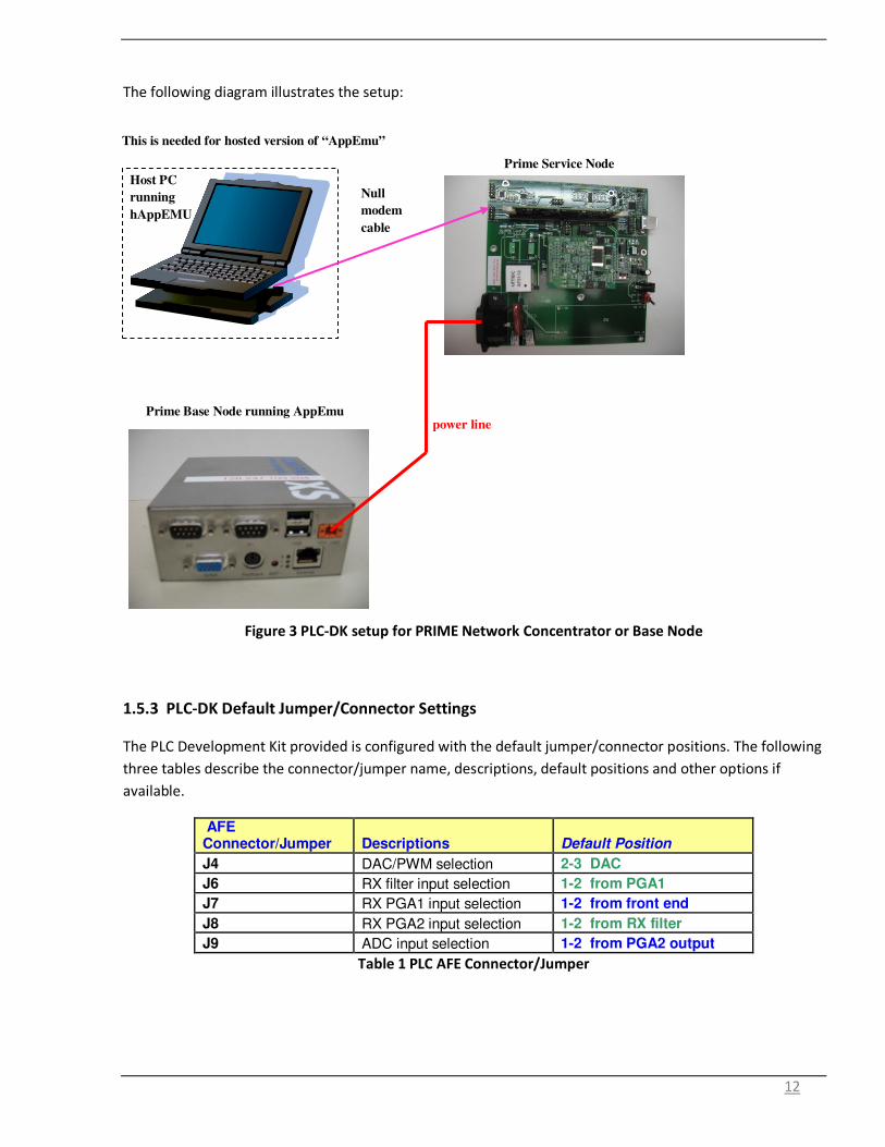
The following diagram illustrates the setup:
Figure 3 PLC-DK setup for PRIME Network Concentrator or Base Node
1.5.3 PLC-DK Default Jumper/Connector Settings
The PLC Development Kit provided is configured with the default jumper/connector positions. The following
three tables describe the connector/jumper name, descriptions, default positions and other options if
available.
AFE Connector/Jumper Descriptions Default Position
J4 DAC/PWM selection 2-3 DAC
J6 RX filter input selection 1-2 from PGA1
J7 RX PGA1 input selection 1-2 from front end
J8 RX PGA2 input selection 1-2 from RX filter
J9 ADC input selection 1-2 from PGA2 output
Table 1 PLC AFE Connector/Jumper
Null
modem
cable
power line
Host PC
running
hAppEMU
This is needed for hosted version of “AppEmu”
Prime Service Node
Prime Base Node running AppEmu

13
PLC Dock Connector/Jumper Descriptions Default Position Options
J1 DSP Control Card Connector
J2 SCI-A Connector
J3 F28335 Boot Options Open Open 1-2 2-3
Boot from Flash Boot from SPI-A Boot from SCI-A
J5 ECAP Channel Selection
2-3 1-2 2-3
ECAP1 ECAP3
J6 SCI-CCAN Bus Connector
J7 GPIO Test Pin Open 2 4 6
GPIO1 GPIO3 GPIO4
J8 Transformer Connection
Close Open Close
T1/ T2 Not Used T1/ T2 Is Used
J9 External Isolated RS232 Power
Open
Open Close
External Power NOT used for RS232 External Power used for RS232
J10 AC Mains Close Open Close
Mains Not Connected Mains Connected
J12 ADC Input Selection 1-2 1-2 2-3
ADC-A1 (F28069) ADC-A0 (F28335)
J13, J14, J15, J16 SPI-A / McBSP-B to AFE031 Selection
2-3
1-2 2-3
SPI – A Select (F2803x) McBSP B Select (F28335)
J17 AC Mains Close Open Close
Mains Not Connected Mains Connected
J18, J19, J20, J21 SPI-A/McBSP-A to PGA AFE031 Selection
1-2 1-2 3-4
SPI McBSP- A to AFE (F28069) PGA McBSP Other to PGAAFE (F28335/03x)
J22
Output Capacitor Band Selection
1-2 1-2 2-3
CENELEC/FCC Less Than 20kHz
J23 Transformer Primary Ratio Configuration Selection
1-3 1-3 3-4
T1 – 1:3, T2 – 1.5:1 T1 – 1:2
J24 Output Inductor Band Selection
7-8
1-2 3-4 5-6 7-8
CENELEC B/C Less than 20kHz FCC CENELEC A
J25 Transformer Secondary Ratio Configuration Selection
2-4 2-4
T1 – 1:4 & 1:2, T2 – 1.5:1

14
M3 AFE Daughter Card Connector
JP1 Power Supply Connector
TB1 Power Line Connector
Table 2 PLC Dock Connector/Jumper
USB/JTAG/SCI Macro Descriptions Default Position Options
J1 Boot Selection Open Open Close
Boot from Flash Boot from SCI-A
J2 JTAG Connector
J3 N/A Open Connected to GPIO34
J4 USB/SCI-B Selection
Close Open Close
SCI-B Not Connected to USB SCI-B Connected to USB
J5 XDS100 Reset Open Open Close
XDS100 Held in RESET XDS100 operating
Table 3 PLC USB/JTAG/SCI Macro

15
2. Using Demo Application – Zero Configuration GUI
Figure 4 Zero Configuration GUI – Starting Screen
The Zero Configuration GUI is a windows application that the PLC-DK user may immediately start performing
text and file transfers, examine the current system information, display the PHY parameters, change the
PHY modulation, display the file and text transfer statistics, and display and save log information.
Note that both transmit and receive stations should be running zero configuration GUI and should not be
paired with PQM
2.1 Configuration
There is no software or PLC configuration is needed to use the Zero Configuration GUI. The only assumption
is that the USB ports (SCI-B) on the PLC are being used.
The first available COMM port on the PC, which may be a USB to Serial Port or a standard COMM port, will
be used to connect to the PCL.
If no available serial ports are found on the PC the Zero Configuration GUI will display an error and exit.

16
If there is no response on the COMM port selected, the Zero Configuration GUI will display a timeout error
and remain active.
If the PLC is connected to another COMM port you may use the use the “Serial Port Connection” drop down
menu to connect to the desired COMM port. If the PLC is not connected, connect the PLC to the desired
port and try again. If the PLC is connected to the correct COMM port reset the PLC.
If the PLC is connected by the PLC serial ports instead of the default USB ports this message will be
displayed.
If you wish to use the PLC serial ports instead of the USB ports the Zero Configuration GUI configuration file
must be changed. This is a XML file that has a number of configuration items that may be changed and
some that should not be changed.
To change the default PLC port to be used, change the “DefaultSCIPort” to “SCI_A” (PLC serial port
connection) or to “SCI_B” (PLC USB port connection) in the configuration file.
The Zero Configuration GUI configuration file will be found here:
“C:\Program Files\Texas Instruments\PLC Application Suite\ PLC_Application_Suite.exe.config”.

17
Below is the table of the items that may be changed and their description.
XML Tag Description Default
Value
Range of Values
ConnectionAttempts This is the number of retries the
GUI will attempt to connect,
initialize, and configure the PLC
before displaying the failed
initialization message box.
3 1- ####
DefaultG3Security This will set the default security
value for G3 data messages.
Security G3 for data transfers is
normally enabled for G3 firmware
versions greater than 1.3.1.0. This
setting can override this behavior
and disable security. If the version
is less than 1.3.1.0 the security is
disabled even if this value is
enabled.
Disabled Enabled
Disabled
FileTransferPageSize This is the number of bytes
transferred at a time during a file
transfer. This does not count the
extra data sent in the data packet
during a file transfer. 24 bytes of
the data packet is used for the file
transfer protocol.
256 1 – Max Packet Size
CloseAllOnExit If this is set to true than all
instances of the Zero Configuration
GUI will close when any instance on
a PC is closed.
False True or False
DefaultSCIPort This is the default SCI port to use.
The data and diagnostic ports must
be set to the same port for the file
transfer
SCI_B SCI_A
SCI_B

18
2.2 Main Screen
The Zero Configuration GUI consists of the main screen where text and file transfers may be performed.
The tabs on the right display significant information about the PLC.
The COMM port attached to is displayed in the title bar. The first available and unopened COMM port is
automatically chosen. The “Serial Port Connection” drop down menu may be used to change the selection
to another COMM port.
From this screen you can perform text message transfers and file transfers with another PLC controlled by
the Zero Configuration GUI.
You may also change the mode by using the ‘Mode’ drop down menu. There are three modes, Zero
Configuration, Intermediate, and Expert.
The Zero Configuration mode is the mode described. Any available COMM port 1-99 will work with the Zero
Configuration GUI.

19
The intermediate mode executes the PLC Quality Monitor using the same COMM port as the Zero
Configuration GUI. When the intermediate mode exits the Zero Configuration reopens the COMM port and
takes control once again. If the COMM port is 10 or above the PLC Quality Monitor will not be able to open
the COMM port and will not function. The COMM port assignment must be changed to a port assignment
1-9 using the Device manager for the PLC Quality Monitor to function.
The Expert is currently disabled for this release.
2.3 Hot Keys
There are several hot keys available. The alpha key is not case sensitive.
<Control I> will close this GUI and execute the PLC Quality Monitor GUI as the intermediate tool.
<Control R> will reset the file transfer statistics. The Statistics received in the Link Quality Report are not
reset. This key stroke combo will reset the statistics screen regardless of what screen has focus in the GUI..
<Control T> will toggle the expert mode menu items on/off depending on their current state.
<Control S> will send a System Information request to the PLC and update the System Info panel when
received.

20
2.4 System Info Panel
The PLC System information is displayed in the first tab. Right clicking on the System Info panel will expose
a context menu with one menu item “Refresh System Information”. This will resend a system information
request to the PLC and refresh the system info panel with the updated information.
Pressing “Ctrl S” will perform the same function without displaying the context menu.
Any value changed will be displayed in red text.
21
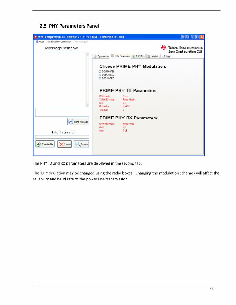
2.5 PHY Parameters Panel
The PHY TX and RX parameters are displayed in the second tab.
The TX modulation may be changed using the radio boxes. Changing the modulation schemes will affect the
reliability and baud rate of the power line transmission

22
2.6 Statistics Panel
The Statistic panel displays information concerning the text and file transfers. Items that have changed are
displayed in red.
Right clicking on the Statistics panel will expose a context menu with a single menu item “Reset Application
Totals”. This will reset totals.
Pressing “Ctrl R” will perform the same function without displaying the context menu.

23
2.7 PHY Test Panel
The PHY Test panel will test communications between two PLC’s using PHY packets. One PLC will transmit
the PHY packets while the other will receive the PHY packets.
To start the test click on the Start PRIME PHY Transmit Test button on either PLC. The statistics will
disappear from the panel since there are no statistics collected on the transmitting PLC. See the figure
below.
It is important to note that Text and File transfers will not work during PHY testing.

24
On the receiving PLC click the Start PRIME PHY Receive Test buttons. The button will change to the “End
PHY Test” state and the statistics will start updating. See below.
To end the test click the “End PHY Test” button on both PLC’s.
25
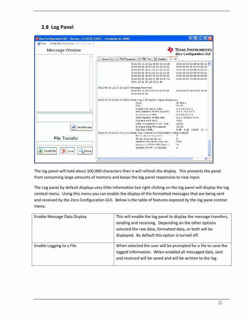
2.8 Log Panel
The log panel will hold about 100,000 characters then it will refresh the display. This prevents the panel
from consuming large amounts of memory and keeps the log panel responsive to new input.
The Log panel by default displays very little information but right clicking on the log panel will display the log
context menu. Using this menu you can enable the display of the formatted messages that are being sent
and received by the Zero Configuration GUI. Below is the table of features exposed by the log pane context
menu.
Enable Message Data Display This will enable the log panel to display the message transfers,
sending and receiving. Depending on the other options
selected the raw data, formatted data, or both will be
displayed. By default this option is turned off.
Enable Logging to a File When selected the user will be prompted for a file to save the
logged information. When enabled all messaged data, sent
and received will be saved and will be written to the log.

26
Log Full Message Data This will display the formatted message data in the log panel.
No data will be displayed unless the “Enable Message Data
Display” is enabled.
Log Condensed Data This will only display the message type and no actual message
data. This reduces the amount of data logged to the screen.
Log Raw Message Data This will display the unformatted message data as a byte
stream.
Clear Display This will clear the log panel. This does not affect data being
logged to a file.
Save to File This will save the current contents of the log panel to a file of
the user’s choosing.
2.9 Sending Text Messages
To transfer text between two connected PLC devices using the Zero Configuration GUI, simply type your text
in the small text box and click on the “Send Message” button. Pressing ‘Enter’ while entering the text will
not send the text message but add a line to your text.

27
When the text is sent the text is moved to the top text box and displayed by the receiving PLC
The form on the left is the sender and the form on the right is the PLC message box receiving the text. You
may send text from either PLC device.
If the text transfer fails the message box below will be displayed.

28
2.10 File Transfers
The file transfer function is contained in the bottom left hand corner.
Click on the ‘Browse’ button to display the standard windows file chooser dialog to choose the file you wish
to transfer. Only one file at a time may be chosen for the file transfer.
After the file is chosen, click on the ‘Transfer File’ button.
The other PLC must also be controlled by the Zero Configuration GUI.
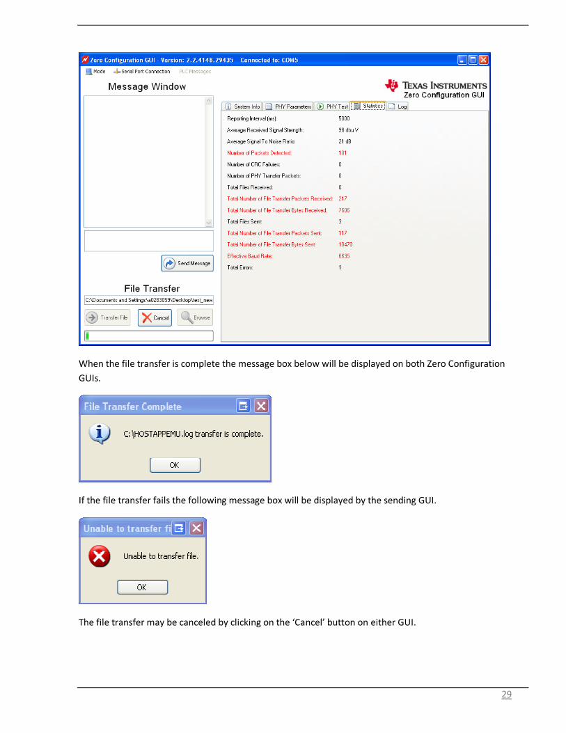
When the transfer starts the GUI will display a progress bar on both Zero Configuration GUIs. The GUI
below is the receiving Zero Configuration GUI and displays the path and file name where the received file is
being copied. The user is not allowed to change the directory path of the received file.
29
When the file transfer is complete the message box below will be displayed on both Zero Configuration
GUIs.
If the file transfer fails the following message box will be displayed by the sending GUI.
The file transfer may be canceled by clicking on the ‘Cancel’ button on either GUI.

30
3. Using Demo Application
The PLC Quality Monitor GUI diagnostic tool - PQM is the window to the PLC-DK user to provide graphical
displays, system information, PHY and MAC parameter configurations and statistics.
3.1 User Interface
The PLC quality monitor consists of the followings:
• Main Menu – All operations are initiated from the main menu with toolbars and buttons.
• Graphical Displays
o PHY Parameters – PHY parameters configuration (see details below)
o RSSI graph – Plot is in dBuV. Note this is limited between 70 dBuV and 98 dBuV.
31
o SNR graph – Plot is in dB.
o Bit Error Rate graph – Plots of PHY layer bit error rate, one line for each MCS (only
applicable to PHY test mode operation)
o Packet Error Rate graph – Plots of PHY layer packet error rate, one line for each MCS
• PHY statistics – This panel provides statistics in the physical link.
• MAC statistics – This panel provides statistics in the MAC and CL layers
• Transfer statistics – This panel provides statistics when file transfer is in operation.
• System Information – This panel provides system version information and PHY/MAC/CL IPv4/LLC
configurations.
3.2 Port Set Up
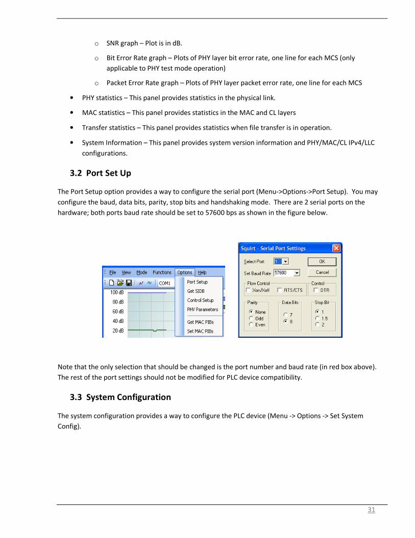
The Port Setup option provides a way to configure the serial port (Menu->Options->Port Setup). You may
configure the baud, data bits, parity, stop bits and handshaking mode. There are 2 serial ports on the
hardware; both ports baud rate should be set to 57600 bps as shown in the figure below.
Note that the only selection that should be changed is the port number and baud rate (in red box above).
The rest of the port settings should not be modified for PLC device compatibility.
3.3 System Configuration
The system configuration provides a way to configure the PLC device (Menu -> Options -> Set System
Config).

32
The following describes the configuration settings:
• Application PIB Attributes
o AppFwVersion – Textual description of firmware version running on device
o AppVendorId - PRIME Alliance assigned unique vendor identifier.
o AppProductId - Vendor assigned unique identifier for specific product.
• Hardware Revision – Docking board revision ID (default: Rev.D)
• Firmware Version – Firmware version ID
• Device Type – The current type of the device
o PRIME IEC-432 LLC Convergence – PRIME standard in IEC432-LLC convergence layer
o PRIME IP Convergence – PRIME standard in IP convergence layer

33
• Device Mode (Automatic flag is only applicable to PRIME IEC432-LLC ) - The current mode of the
device.
o PRIME IEC-432 Point-to-Point – using the end-to-end setup between the two PLC devices.
This mode interfaces with the eMeter GUI performing its functions such as PHY testing, File
Transfer, Message Transfer, etc.
o PRIME_ IEC432 - eAppEMU MAC mode – embedded AppEMU application is running, in
F28069 and interfaces directly with MAC layer in PRIME network with the base node.
o PRIME IEC543 - eAppEmu IEC432-LLC mode – embedded AppEMU application is running in
F28069 and interfaces with IEC432-LLC layer in PRIME network with the base node.
o PRIME IEC432-LLC - AUTO – for host eMeter applications such as hostAPPEMU running in
PC and communicate with TI PLC at IEC61334-4-32 LLC layer through UART based on TI Host
Message Protocol. It performs network registration and connection establishment
automatically.
o PRIME IEC432-LLC – for host eMeter applications such as hostAPPEMU running in PC and
communicate with TI PLC at IEC61334-4-32 LLC layer through UART based on TI Host
Message Protocol. It does not perform network registration and connection establishment
automatically.
o PRIME IEC432 MAC – for host eMeter applications such as hostAPPEMU running in PC and
communicate with TI PLC at PRIME MAC layer through UART based on TI Host Message
Protocol.
• Use Message Header RPY Bit As Flow Control
o When selected or enabled, the PLC device will set message header RPY bit to 1 during
DATA_TRANSFER message used for Data.Indicate (Rx Data Path) to provide flow control for
host device. (Host has to send an ACK to PLC before next DATA_TRANSFER.Indicate will be
sent to host).
• Serial Ports
o Data port
� The Data Port is the serial port the PLC device used for host and PLC communication
following “plcSUITE host message protocol”. This can be either SCI-A or SCI-B on
Rev C. hardware and newer. This port is used by a host application (hostAPPEMU)
to communicate with the PLC device.
o Diagnostic port
� The Diagnostic Port is the serial port the PLC device uses to transfer diagnostic
messages to the PLC Quality Monitor or Logger Tools. This can be either SCI-A or
SCI-B on Rev C. hardware and newer. If using IEC432/LLC, the Diagnostic port can
be shared with Data port if required, however, if using IPv4, the Data port and
Diagnostic port must be different and cannot be shared.
Note that SCI-B shall not be selected for docking board HW prior to Revision C
• System
o Serial Number

34
� A maximum 16 octet string representing the device serial number, . entered as
####-####-####, where # can be 0-9, a-f.
o Serial Number Length
� The length of valid octets in the 16 octet serial number
o EUI address
� The hexadecimal EUI-48 of the PLC device, entered as ##:##:##:##:##:##, where #
can be 0-9, a-f.
• PHY
o PRIME – PRIME standard mode
o PRIME ROBO – non-PRIME standard PHY robust mode
• MAC
o Default ARQ enabled: ARQ is enabled by default
o Default PAC enabled: Packet Aggregation enabled by default
o Rx Max Hold PPDU: maximum number of PPDUs Rx MAC can hold
o Maximum number of connection: default maximum number of simultaneous connections
o Maximum connection queue length: default maximum queue sizes
o Default Security profile
• CL IPv4
o Source address
o Netmask
o Gateway
• IEC61334-4-32 LLC
o Src LSAP – The local LSAP involved in the data unit transmission
o Default destination LSAP
� The default destination LSAP used by the eAppEMU when in eAppEMU interfaces
with IEC61334-4-32 LLC
o Default destination MAC address
� The default destination node address used by the eAppEMU when in eAppEMU
interfaces with IEC61334-4-32 LLC
The following example illustrates how to change the device type from “IEC432-LLC” to “Point-to-Point”:
1. Menu -> Options -> Set System Config
2. Pull down menu from Device Type
3. Select Point to Point
4. Click OK

35
The following window will pop up and selecting “YES” will reset the PLC device and new device mode will be
in effect.

36
3.4 Getting System Information
The Get System Info option (Menu->Options->Get System Info) retrieves the current System Information
values from the PLC-DK. These are represented in the System Information view. These values may be set
using the Set System Config (Menu->Options->Set System Config).
3.5 Control Set Up
The Control Setup option (Menu->Options->Control Set up) allows the followings:
• Channel status update - Select “Enable Synchronization Parameters” check box for status
display in statistic window.
• Link quality report update - Select “Enable Link Quality Report” check box for RSSI/SNR/BER/PER
display in the statistics window.
• MAC statistic update – Select “Enable MAC statistics” check box for MAC statistics display in
MAC statistic window.
• Update period in seconds – Enter duration between statistics updates.

37
Note that if both transmit and receive PLC LQM tool is running on the same PC, it is recommended to use a
larger update periods (e.g. 3 seconds) to avoid too many traffic between device and host PC.
3.6 Configuring PHY Parameters
The PHY parameters configuration (Menu->Options->PHY parameters) is used for configuring the PHY
transmitter (Red Box below) and receiver parameters (Green Box below).

38
Note that the enabling of PHY “Test Mode” on the Transmit or Receive would require the device mode to be
“Point to Point”. The following window will be prompted if device is not already in “Point to Point”. Click
“Yes” to reset the device and “Point to Point” mode will be set. The PHY test can now be continued,
The following describes the PHY TX parameters that can be configured:
• ROBO – PHY Robust mode (non-PRIME standard)
• PRM – When enabled, it performs PHY Robustness Management as described in the PRIME
standard and manages the modulation and FEC selections. The modulation/FEC selection from
this panel will be ignored. PRM will not take effect if PHY test mode is selected.
• Modulation – DBPSK, DQPSK, D8PSK. Note this field is ignored if sweep MCS is selected. If ROBO
mode is selected, then DBPSK + 1/4 repetition or DBPS + 1/8 repetition can be selected.
• FEC - ON or OFF. Note this field is ignored if sweep MCS is selected. If ROBO mode is selected,
this field is not valid since FEC is always on.
• Level – Transmit Level
(Note that the maximum transmit level should be set to 2 for AFE HW prior to Revision C)
0 : Maximum Output Level (MOL)
1 : MOL – 3dB
2 : MOL – 6dB
3 : MOL – 9dB
4 : MOL – 12dB
5 : MOL – 15dB
6 : MOL – 18dB
7 : MOL – 21dB
The following describes the PHY TX parameters that can be configured for PHY Tx test mode only:
• Test Mode - When enabled, it configures the transmitter in test mode and it transmits fixed
data pattern (selected in data pattern box) for BER testing
• Sweep MCS – When enabled, test will sweep through all MCS for the packets transmitted. The
order of MCS used is DBPSK, DQPSK, D8PSK, DBPSK+FEC, DQPSK+FEC and D8PSK+FEC.
• Sweep PPDU length - When enabled, test will sweep through all valid PPDU length in increasing
order for the MCS used.
• Continuous – When enabled, test will continuously transmit PPDUs as specified. When disabled,
test will transmit the “Number of PPDUs per setting” (see below) as specified and stop. .
• Data Pattern – When PHY test mode is enabled, data pattern for the packet payload to be
transmitted can be selected. The following data patterns are available:
o A ramp data pattern from 0 to 255
o A fixed data byte set by octet value

39
o PRIME certification data pattern (PRIME IS A WONDERFUL TECHNOLOGYPRIME IS A
WONDERFUL TECHNOLOGY) with no space between 2 sentences.
The data pattern is repeated for the duration of the payload.
• PPDU length – PPDU length in bytes. Note this field will be ignored when sweep PPDU length is
selected. The current firmware version supports a PPDU length of 1 byte to 756 bytes. It is also
governed by maximum length allowed for the selected modulation scheme.
• Inter-PPDU time – The gap time between PPDU in unit of 10 microseconds.
• Number of PPDUs per setting – The number of PPDU per setting during MCS sweep, PPDU
length sweep or MCS/PPDU length sweep.
The following describes the PHY Rx Parameters can be configured:
• AGC – If selected, receiver performs automatic gain control. If unselected, manual gain setting is
used. Valid gain values are from 0 to 7 with step of 6dB.
The following describes the PHY Rx Parameters can be configured in PHY Rx Test mode only:
• Test Mode - When enabled, receiver will start comparing receive packet using the data pattern
selected and compute BER for BER testing.
• Data Pattern – When test mode is enabled, it can select data pattern used for comparison in
computing BER. A ramp data patter from 0 to 255 or a fixed data byte set by octet value. Note
this should be identical to the selection in the transmitter for valid BER result.
The following describes the PHY System Parameters:
• AGC Gain Min – Minimum AGC gain in dB
• AGC Gain Max – Maximum AGC gain in dB
• AGC Gain Step – Step size of AGC in dB
3.7 Get/Set MAC PIB
MAC PIB (PRIME standard Section 4.5.1-MAC variable attributes) can be configured as follows (Menu-
>Function->Set MAC PIBs):

40
MAC PIB (PRIME standard Section 4.5.1 – MAC variable attributes) can be retrieved as follows (Menu-
>Function->Get MAC PIBs):

41
3.8 Get PHY PIB
PHY PIB (PRIME standard Section 3.10.1 PHY statistical attributes and 3.10.2 PHY Implementation attributes)
can be retrieved as follows (Menu->Function->Get PHY PIBs):

42
3.9 Testing PHY Performance
The PHY performance can be tested in a point-to-point configuration where system configuration steps
described on Section 2.3 should be used. One modem should be configured as transmitter in test mode and
the other modem as receiver in test mode (Menu->Options->PHY Parameters). The HW should be set up as
described in Section 1.5.1. An example for PHY test with DBPSK+FEC, transmitting at level -9 dB, PPDU
length of 100 bytes and inter-PPDU interval of 100 us in continuous mode is shown.
Note it does not support concurrent bi-directional data transfer.

43
Note that the enabling of PHY “Test Mode” on the Transmit or Receive would require the device mode to be
“Point to Point”. The following window will be prompted if device is not already in “Point to Point”. Click
“Yes” to reset the device and “Point to Point” mode will be set. The PHY test can now be continued.
By enabling the channel status and link quality report and setting report period (as described in Section 4.2),
the PHY performance (SNR/RSSI/PER/BER) will be displayed in the graphs and the statistics will be displayed
in the statistics panel.
3.10 Sending and Receiving Message
The Send Message function (Menu->Function->Send Message) sends a small text message from the one
device to another in point-to-point configuration. It is intended to test and verify communication between
the two systems in a point-to-point configuration.

44
Note that this operation would require the device mode to be “Point to Point”. On the transmitting device,
the following window will be prompted if device is not already in “Point to Point”. Click “Yes” to reset the
device and “Point to Point” mode will be set. Message send can then be continued,
On the receiving device, the device mode must be set to “Point to Point” following steps described in
Section 2.3
Note that the connection type such as ARQ enabled, PAC enabled or security profile used for the message
send can be modified via System configuration settings using steps described in Section 2.3.
When this option is selected, you may fill in a message and press send, and the other host will display the
message.
Note that the connection type such as ARQ enabled, PAC enabled or security profile used for the message
send can be modified via System configuration settings using steps described in Section 2.3.
3.11 Sending and Receiving File
The Send File function (Menu->Function->Send File) sends file from one device to another in a point-to-
point configuration.
Note that this operation would require the device mode to be “Point to Point”. On the transmitting device,
the following window will be prompted if device is not already in “Point to Point”. Click “Yes” to reset the
device and “Point to Point” mode will be set. Message send can then be continued,
On the receiving device, the device mode must be set to “Point to Point” following steps described in
Section 2.3

45
Note that the connection type such as ARQ enabled, PAC enabled or security profile used for file transfer
can be modified via System configuration settings using steps described in Section 2.3.
This function is not a guaranteed error-free delivery (the file received may have dropped packets) and is a
means to push data from one board to another. The receiver will note both payload CRC and missing packet
errors and will attempt to notify the sender of these errors.
There are two modes for file transfer, stream and non-stream. Stream mode streams packets to the
receiver without waiting for the receiver to acknowledge receipt. A No NACKS option is also allowed in
stream mode. If un-selected, it requests receiver to only send NAKs when there is error. In non-stream
mode the receiver must ACK each packet before the sender will send the next.
The packet size may also be specified. This value represents the total packet size, including any protocol
headers. If an invalid size is entered, when Send is pressed, the following error will be displayed.
Once the file transfer begins, the Transfer Information section reflects transfer statistics.

46
Statistics may be cleared by selecting “File/New” or by pressing the New File button.
The transfer may be aborted by either the sender or receiver. The sender may abort by pressing the Abort
button and the receiver may abort by selecting the menu option “Functions/Abort file receive”.

47
3.12 Flash Firmware
The flash firmware function (Menu->Function->Flash Firmware) downloads the new firmware image to the
DSP control.
The following steps should be used:
1. Enter the PRIME application “s record file” and press the Flash button, you will see that Flash
upgrade application is erasing the Flash.
For example, the “prime_appemu_sn_flash.srec” should be used for the PRIME service node test

48
2. After Flash is erased, you will see the programming is in progress (packet by packet).
3. After programming is complete, you will see the following window. The new downloaded firmware
will boot up.

49
4. Running PRIME Service Node “AppEmu” Application
The “AppEmu” application demonstrates eMeter reading and other operations in a PRIME network that
composed of one base node and several service nodes. The binary “prime_iec432_f2806x.out” should be
flashed onto the F28069 and the HW should be set up as described in Section 1.5.2. It requires a PRIME
compliant Base Node also running similar “AppEmu” application. This demo includes the following PRIME
procedures:
• Registration
• Keep Alive
• Connection/Disconnect
• CSMA/CA access in PRIME SCP period
• Application data traffic
There are two versions of “APPEMU”, one version is a self contained embedded application (eAppEMU) and
a second version is a host based application (hostAppEMU).
Note that both eAppEMU and hostAppEMU supports the following two modes:
• AppEmu interfaces to IEC61334-4-32 LLC layer with data traffic of LLC L_SDU
• AppEmu interfaces directly to PRIME MAC with data traffic of MAC MPDU
The system configuration described in Section 3.3 should be used to configure for the above modes and a
device reset from the GUI is required for the system configuration change to take effect. In order to inter-
operate against a PRIME Base Node, the PRIME Base Node needs to support both types of emulation.
4.1 Embedded AppEmu
This is a self contained version running embedded “eAppEmu” on the target device. No host machine is
required to run eAppEMU.
4.2 Host Based AppEmu
Host based AppEMU is running on a Windows console application called “HostAppEMU”. The host tool
“HostAppEMU” should be run when PLC device is set as: “IEC432-LLC” or “MAC” and the PLC will
communicate with the HostAppEMU through UART according to TI Message Protocol. The application has
several command line options available:

50
-p [#]
Sets the COM port. Appropriate values are “1” for COM1, “2” for COM2, etc.
-b [#]
Set baud rate (default to 57600)
-h [#]
Sets the Host Port. The Host Port is the port (SCI-A or SCI-B) that is designated to receive Host
Messages, as defined by the PLC Suite Host Message Protocol Specification.
-x
Sets HostAppEMU to P2P (Point-To-Point). In this mode, the application will operate as if connected
to another PLC device. You can sendc a text message or transfer a file to another HostAppEMU
application running with another device..
-m
Sets HostAppEMU to MAC Mode. In this mode, the application will interface the MAC layer to
perform its tasks. For example, when opening a connection to the Base Node, the MAC Open
Connection will be used.
-l
Sets HostAppEMU to LLC Mode. In this mode, the application will interface the IEC432 LLC layer on
the device to perform its tasks. For example, when transferring data to the Base Node, the LLC
Data_Transfer.Request will be used, and the LLC Layer will take care of sending the data to the Base
Node.
-i

51
Sets HostAppEMU to IP Mode. In this mode, the application will interface the IP CL layer on the
device to perform its tasks. For example, when transferring data to the Base Node, normal IP
datagrams are used, such as UDP, TCP, ICMP, etc. A source and destination address must be
specified.
-s [addr]
Sets the IP source address. This determines which interface the datagrams will be sent on and
should reflect the source address of the device.
-d [addr]
Sets the IP destination address. This determines which IP address datagrams are destined for.
-u [#]
Sets the UDP destination port.
-o [#]
Sets the UDP host port.
-t [text]
Sends a text message to another device. The device must be in P2P mode for this option.
-f [file]
Sends a file in stream mode to another device. The device must be in P2P mode for this option.
-r <#>
Use RPY <optional delay # sec before sending reply>
-F [filename]
Flash the device after a firmware download from power line is received. If the file name is specified,
the is compared to the file sent by the PLC and not flashed.
The following window shows when the –m option is selected where HostAppEmu MAC mode is used:
52
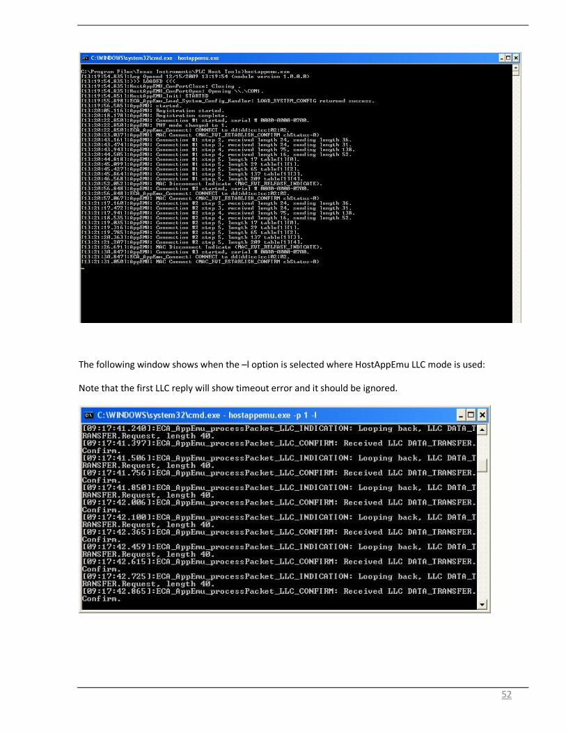
The following window shows when the –l option is selected where HostAppEmu LLC mode is used:
Note that the first LLC reply will show timeout error and it should be ignored.

53
4. Running a Point to Point file transfer with Host Application
The HostAppEMU application demonstrates file transfer in a point to point configuration. The binary
“prime_iec432_f2806x.out” should be flashed onto the F28069 and the HW should be set up as described in
Section 1.5.1.
5. Running Firmware Download from Power line with Host
Application Support
Note this is not supported in current release.
The HostAppEMU application supports firmware download from power line from Base Node as specified in
the PRIME spec. The binary “prime_iec432_f2806x.out” should be flashed onto the F28335. When Base
node initiates the firmware download procedure, the received sectors are being transferred to the host and
stored in host memory. Once the download is completed, the firmware instructs the host to update the
flash and continue to complete the remaining handshakes with the Base node.
The following window shows when the –F option is selected where HostAppEmu LLC mode is used:

54
6. Running Serial Profile Communication
Note this is not supported in current release.
Prime management PIB retrieval/set via serial profile communication requires the following set up:
1. Connect PLC Quality Monitor (PLCQM) to SCI-A (Serial D connector) and launch PLCQM
2. Options->Set System configuration, Configure Host Port and Diag Port to SCI-A port
3. Connect test tool to SCI-B (USB connector). Management PIB retrieval/set using serial profile
communication can be proceeded.
4. When test is done, connect PLCQM to SCI-A (Serial D connector) and PLCQM can resume. The port
can be configured back to SCI-B if desired.

55
7. System Trouble Shoot
7.1 Trouble shoot for squirt
The Serial Port is muxed by a driver called Squirt. The driver’s interface is on the windows taskbar. There
may be times that the driver has to be reset because no data is being forwarded to/from the applications.
To reset the Squirt driver, either right click the Squirt Taskbar Icon and select “Reset” or double click the
Squirt Taskbar Icon (which will momentarily turn green to indicate reset).
In the event of application exception (conditions where the applications have encountered a severe error
and is terminated), the Squirt Driver may require termination cleanup. When this occurs, you must exit any
PLC Host tools (PQM, Logger, etc.) and terminate the Squirt Driver by selecting all Squirt tasks (both
SQUIRT*.exe and SquirtSerialPort.exe) from the Task Manager and ending their process.
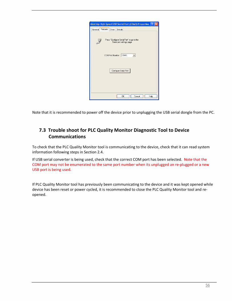
7.2 Trouble shoot for USB to Serial Dongle Communications
When the USB to serial dongle is plugged into the PC, the enumerated COM port can be found from system
properties->Hardware->device manager as follows:
Note that the enumerated COM port needs to be lower than “COM19”. If not, it can be changed by selecting
the corresponding serial port, right click and click on “properties”. Then select the “features” panel and the
COM port can changed.
56
Note that it is recommended to power off the device prior to unplugging the USB serial dongle from the PC.
7.3 Trouble shoot for PLC Quality Monitor Diagnostic Tool to Device
Communications
To check that the PLC Quality Monitor tool is communicating to the device, check that it can read system
information following steps in Section 2.4.
If USB serial converter is being used, check that the correct COM port has been selected. Note that the
COM port may not be enumerated to the same port number when its unplugged an re-plugged or a new
USB port is being used.
If PLC Quality Monitor tool has previously been communicating to the device and it was kept opened while
device has been reset or power cycled, it is recommended to close the PLC Quality Monitor tool and re-
opened.

57
APPENDIX A - PLC-DK Hardware Resource Usages
Table 4 PLC-DK GPIO pins configurations
GPIO PIN Connected to Pull Up PRIME Build Usage
GPIO00 PWM_1A Enabled
Transmit
GPIO01 TP Enabled
GPIO02 PWM_2A Enabled
Transmit
GPIO03 TP Enabled
XINT2, TFLAG
GPIO04 TP Disabled
XINT1, HALT
GPIO05 ZeroCross (opt) Disabled
Alternate Zero Cross Input
GPIO06 LED_AFE1 Disabled
Beacon Indication (toggle per rx beacon)
GPIO07 LED_AFE2 Disabled
Beacon Acquired (on)
GPIO08 LED_AFE3 Disabled
Registration with BN completed (on)
GPIO09 ZeroCross (main) Enabled
Zero crossing capture input
GPIO10 Disabled
GPIO11 Disabled
GPIO12 TXDRVEN Enabled
OPA enable pin
GPIO13 Disabled
GPIO14 SCI (SCITXDB) Enabled
UART host port
GPIO15 SCI (SCIRXDB) Enabled
UART host port
GPIO16 SPI (SPISIMOA) Enabled
PGA (option)
GPIO17 SPI (SPISOMIA) Enabled
PGA (option)
GPIO18 SPI (SPICLK) Enabled
PGA (option)
GPIO19 SPI (SPISTEA) Enabled
PGA (option)
GPIO20 McBSP (MDXA) Enabled
F28069 AFE031 connection
GPIO21 McBSP (MDRA) Enabled
F28069 AFE031 connection
GPIO22 McBSP (MCLKXA) Enabled
F28069 AFE031 connection
GPIO23 McBSP (MFSXA) Enabled
F28069 AFE031 connection

58
GPIO24 McBSP (MDXB) Enabled
F28335 AFE031 connection
GPIO25 McBSP (MDRB) Enabled
F28335 AFE031 connection
GPIO26 McBSP (MCLKXB) Enabled
F28335 AFE031 connection
GPIO27 McBSP (MFSRB) Enabled
F28335 AFE031 connection
GPIO28 SCI (SCIRXDA) Enabled
UART diagnostic port
GPIO29 SCI (SCITXDA) Enabled
UART diagnostic port
GPIO30 CAN RX Enabled
CAN Bus Rx Port
GPIO31 CAN TX Enabled
CAN Bus Tx Port
GPIO32 (I2C) SDAA Enabled
EEPROM
GPIO33 (I2C) SCLA Enabled
EEPROM
GPIO34 LED Enabled
LED ?
GPIO35 Enabled
GPIO36 Enabled
GPIO37 Enabled
GPIO38 Enabled
GPIO39 Enabled
GPIO40 Enabled
GPIO87 LED Enabled
LED available on F28335 ControlCard
Table 5 PLC-DK Peripherals and Interrupts Usage
Peripherals PRIME Build Usage Interrupt
32-bit CPU Timers
Timer 0
1. During packet transmission - Trigger Tx DMA to ePWM/HRPWM @ 500 kHz 2. CSMA - Track PRIME frame structure PIE 1.7
Timer 1 Absolute timer (PRIME PHY Time Stamp)
Timer 2 DSP-BIOS Systick INT14
Watchdog Timer
TBD (Reset)
ADC
Rx ADC samples @ 250 kHz

59
McBSP
McBSPA AFE031 inteface (SPI mode)
SCI
SCIA Diagnostic port PIE 9.1 - Rx PIE 9.2 - Tx
SCIB Host port PIE 9.3 - Rx PIE 9.4 - Tx
I2C
Interface to EEPROM
Ecap
eCAP3 Zero crossing measure
eCAP4 Zero crossing measure
DMA
Channel 1 ADC PIE 7.1
Channel 2 DAC (McBSPA) PIE 7.2
Table 6 PLC-DK Flash Configurations and Usage
Sectors Size (words) Prime Build Usage
A 16K Code Start Image
B 16K
Prime image
C 16K
D 16K
E 16K
F 16K
G 16K
H 16K Firmware upgrade image
Table 7 PRIME System Memory and MIPs usage
MEM/MIPS BenchMark
FLASH 190 kB
RAM 68 kB
MIPS Average 82 MIPs

60
APPENDIX B – Logger Setup
A PLC Event Logger can be used for diagnostic purpose. Set up communication Port (via Logger Settings).
• Goto View
• Click on Settings
• Select the check box for PLC Logger 1(COM1)
• Highlight PLC Logger 1

61
• Click Setup and select communication port used for connecting to the serial connection on the
docking board. In this example, it uses COM1 port.

62
• Click on Setup and configure serial port as follows:

63
APPENDIX C – PHY Example Project
The PHY examples demonstrate the calling of PHY library API when HW is setup with 2 devices connected
via power line. One device will send one packet and wait for one receive packet and then transmit another
packet. This alternates between Tx and Rx. The packet is of size of 756 bytes with a repeating ramp data
pattern using the followings:
Modulation: DBPSK with FEC enabled
PPDU payload length: 40 bytes
1. Unzip ti_prime_phy_example.zip
2. Start CCS4 and create new workspace
3. In CCS4, import prime phy test project into workspace (Menu Project->Import Existing CCS/CCE
Eclipse Project)
4. In CCS4, Build project (Menu Project->Project->Build Project)
5. In CCS4, launch debugger for the selected target configuration
6. In CCS4 debugger, connect target (Menu->Target->Connect target)
7. In CCS4, Load phy_tx_rx_lib.out (Menu->Target->Load Program)
8. In CCS4, Reset, Run (Menu->Target->->Run) and LED flashes.
9. Load the same code to the second board.
10. Connect the two boards via power line cables. Both boards should be alternating between Rx and Tx
and the LEDs should be blinking.

64
Source File Description
• Test bench
– Project file: .cdtbuild, .cdtproject, .project, .ccsproject
– Test bench: test_tx_rx.c demonstrates alternating PRIME PHY Tx and PHY rx using provided PHY
library
– Linker command:F28069.cmd
– Test example for flash
• Header files
– PHY common: phy.h
– PHY Tx: phy_tx.h
– PHY Rx: phy_rx.h
– HAL: hal_afe.h
– Chip support library header files
• Libraries
– PHY lib: phy_lin_afe031_f2806x.lib
– HAL lib: hal_afe031_f2806x.lib
– Chip Support lib: csl.lib
PHY Library Demonstration
• The PHY library example project demonstrates packet transmission and reception at the physical
layer in a TDD fashion.
• Flash 2 F28069 boards with PHY library example executable.
• Connect via powerline
• Sequence of operation
– Board A sends a packet
– Board B receives packet and sends a packet back to board A
– This will be repeated.
– LED on DSP control card will blink if packet transmission and reception is ongoing
Hardware Resource Usage
The PHY library uses the following HW resources:
• DMA Channels o Channel 1 – Receive ADC input
o Channel 2 – Transmit DAC (McBSPA) output
• CPU Timers o Timer 0 – PHY
o Timer 1 – PRIME PHY System Timer 20-bits in 10us increment
o Timer 2 – Not Used
• GPIO a. GPIO 00 – PWM_1A

65
b. GPIO 02 – PWM_2A
c. GPIO 12 – OPA Enable
PHY Library Test Bench Steps
• HW initialization (F28069 specifics)
• Flash configuration
• ISR Installation
– Timer 0 (PHY_tx_cpuTimer0_isr)
– DMA channel 1 (PHY_rx_dintch1_isr)
– DMA channel 2 (PHY_tx_dintch2_isr)
• AFE initialization
– HAL_afeTxInit
– HAL_afeRxInit
• PHY library initialization
– PHY_txInit
– PHY_rxInit
• Generate packet for transmission
• Start PHY Rx to listen to line
– PHY_rxStart(0xFFFF, cb_sync)
• Callback for PHY_rxStart- cb_sync
• If status is success, start PPDU decode (only 1 time)
- PHY_rxPpduStart(cb_ppdu)
• Callback for PHY_rxStart - cb_ppdu
• If status is success, do some processing if needed and release buffer back to PHY
-PHY_rxPpduRelease
- LED toggle

66
Start packet transmission
– PHY_txPpdu(&PHY_tx_ppdu_s, cb_tx);
• Enable system interrupt
• Main loop repeats
ISR Descriptions
• CPU Timer 0 ISR – Start packet transmission @ specified time
interrupt void PHY_tx_cpuTimer0_isr(void)
{
txSymbDone = 1;
HAL_cpuTint0Func();
}
• DMA1 Channel ISR – Incoming ADC samples ready for process @ symbol rate
interrupt void PHY_rx_dintch1_isr(void)
{
/* Set ready flag */
afeReadyFlag = 1;
/* Call HAL AFE function for dma handling */
HAL_afeRxDmaCh1IntFunc();
}
• DMA2 Channel ISR – Outgoing PWM completed @ symbol rate
interrupt void PHY_tx_dintch2_isr(void)
{
txSymbDone = 1;
HAL_afeTxDmaCh2IntFunc();
}
Main Loop
• Wait for DMA channel 1 ready (incoming ADC samples ready)
– Perform PHY Rx processing
• PHY_rxSmRun
• If Incoming packet is completed
• Callback for PHY_txPpdu - cb_tx
• If status is success, do some processing if needed.

67
– Initiate a packet transmission
• PHY_txPpdu
• Wait for DMA channel 2 ready (output PWM samples done)
– Perform PHY Rx processing
• PHY_txSmRun
– Note that when packet transmission, PHY Rx will be suspended and when packet
transmission is completed, PHY Rx will be resumed.

68
APPENDIX D – Host Example Project
The Host Example Project (hAppEMU) is the host based eMeter Application Emulator. It provides the same
functionality as the embedded AppEMU except it is written as an external host application that
communicates to the PLC device via Host Messages over the serial port.
Host AppEMU is a Windows console application. The project is a Visual Studio 2008 solution.
1. Unzip host_appemu.zip
2. From Visual Studio 2008, open the hostappemu.sln Solution file.
3. Rebuild the project (Build->Rebuild Solution)
4. Once the project has built, the Host AppEMU executable (hostappemu.exe) may be ran.
5. Reference the section above detailing the command line options and operation.
The following shows examples of host messages send sequences. The corresponding replies should follows.
Scenario 1: Host Applications communicating to the device with device in “PRIME IEC432 LLC Convergence ”
mode with automatic flag set:
1. “LOAD_SYSTEM_CONFIG” , Config Type 0x0003 (System Configuration), to configure device in
“PRIME IEC432 LLC Convergence” mode with “automatic flag” enabled
2. “SHUT_DOWN” with soft reset
3. “DATA_TRANSFER”
Scenario 2: Host Applications communicating to the device with device in “PRIME IEC432 LLC Convergence ”
mode with non-automatic flag set:
1. “LOAD_SYSTEM_CONFIG”, Config Type 0x0003 (System Configuration), to configure device in
“PRIME IEC432 LLC Convergence” mode with “automatic flag” disabled.
2. “SHUT_DOWN” with soft reset
3. “CL_ESTABLISH”
4. “DATA_TRANSFER”
5. “CL_RELEASE” when the connection is to be torn down
Scenario 3: Host Applications communicating to the device with device in “PRIME IEC432 MAC ”:
1. “LOAD_SYSTEM_CONFIG” , Config Type 0x0003 (System Configuration), to configure device in
“PRIME IEC432_MAC” mode
2. “SHUT_DOWN” with soft reset
3. “NETWORK_REGISTER”
4. “CONNECT”
5. “DATA_TRANSFER”

69
6. “DISCONNECT” when connection is to be torn down
7. “UNREGISTER” when device to leave the network

70
APPENDIX E –Packet Examples: File/Message Tranfer
The PLC Quality Monitor tool provides two simple applications: message transfer and file transfer. These
applications operate in a point to point configuration. The HW should be set up as described in Section
1.5.1.These applications communicate with the host message protocol on top of Prime software stack via
UART. The basic packet format used for file/message transfer follows that described in PLC Suite Host
Message Protocol Specification. Here, some packet examples are provided.
Message Transfer
Example 1: Data Transfer Request (“HI”) Header (Host Message Protocol)
Octet 0 1 2 3 4 5 6 7
Data (in hex) 00 82 28 00 75 DA C6 3B
Description Message
Type (Data
Transfer)
ORG=1,
RPY=0,
REV=0,
SEQ=2
Length(LSB) Length(MSB)
Header
CRC16
(LSB)
Header
CRC16
(MSB)
Payload
CRC16
(LSB)
Payload
CRC16
(MSB)
*Length=Header CRC(2B)+Payload CRC(2B)+Mode(2B)+LSAP(2B)+Destination Addr. (2B)+Rsvd(4B)+Data Payload(26B)=40B
Payload (Host Message Protocol)
Octet 8 9 10 11 12 13 14 15
Data (in hex) 01 00 00 00 00 00 00 00
Description (LSB) Mode (MSB) Dst. LSAP Src. LSAP Destination Address Reserved
* Mode 0x0001: Data Transfer Request
Payload (Host Message Protocol)
Octet 16 17 18 19 20 21 22 23
Data (in hex) 00 00 AA AA 00 00 00 00
Description Reserved Type (Message Transfer
App) Subtype (Transfer) Status
Payload (Host Message Protocol)
Octet 24 25 26 27 28 29 30 31
Data (in hex) 00 00 00 00 00 00 01 00
Status Message Id (=0) (LSB) Page number
Payload (Host Message Protocol)
Octet 32 33 34 35 36 37 38 39
Data (in hex) 00 00 01 00 00 00 02 00
Description Page number (MSB) (LSB) Total # of pages (MSB) (LSB)Message size (=2B)
Payload (Host Message Protocol)
Octet 40 41 42 43
Data (in hex) 00 00 48 49
Description Message size (MSB) “H” “I”
*Blue color: Application Protocol Data Unit, which is part of message control protocol payload.

71
File Transfer
Example 1: File Transfer (the first packet)
Header (Host Message Protocol)
Octet 0 1 2 3 4 5 6 7
Data (in hex) 00 81 32 00 9D 6F CE 18
Description Message
Type (Data
Transfer)
ORG=1,
RPY=0,
REV=0,
SEQ=1
Length(LSB) Length(MSB)
Header
CRC16
(LSB)
Header
CRC16
(MSB)
Payload
CRC16
(LSB)
Payload
CRC16
(MSB)
*Length=Header CRC(2B)+Payload CRC(2B)+Mode(2B)+LSAP(2B)+Destination Addr. (2B)+Rsvd(4B)+Data Payload(36B)=50B
Payload (Host Message Protocol)
Octet 8 9 10 11 12 13 14 15
Data (in hex) 01 00 00 00 00 00 00 00
Description (LSB) Mode (MSB) Dst. LSAP Src. LSAP Destination Address Reserved
* Mode 0x0001: Data Transfer Request
Payload (Host Message Protocol)
Octet 16 17 18 19 20 21 22 23
Data (in hex) 00 00 BB BB 00 00 00 00
Description Reserved Type (File Transfer App) Subtype (Transfer) Status
* status 0x00000000: success
Payload (Host Message Protocol)
Octet 24 25 26 27 28 29 30 31
Data (in hex) 00 00 01 00 00 00 00 00
Status Message Id (=1) (LSB) Page number
Payload (Host Message Protocol)
Octet 32 33 34 35 36 37 38 39
Data (in hex) 00 00 08 00 00 00 F7 07
Description Page number (MSB) (LSB) Total # of pages (MSB) (LSB)Message size (=2KB)
*page number 0x00000000: the first page
Payload (Host Message Protocol)
Octet 40 41 42 43 44 45 46 47
Data (in hex) 00 00 43 3A 5C 65 72 72
Description Message size (MSB) File message
Payload (Host Message Protocol)
Octet 48 49 50 51 52 53 54 55
Data (in hex) 6F 72 2E 6C 6F 67
Description File message
*Blue color: Application Protocol Data Unit, which is part of message control protocol payload.
Example 2: File Transfer (the last packet)
Header (Host Message Protocol)
Octet 0 1 2 3 4 5 6 7
Data (in hex) 00 89 1D 01 C5 C0 71 9C
Description Message
Type (Data
Transfer)
ORG=1,
RPY=0,
REV=0,
SEQ=9
Length(LSB) Length(MSB)
Header
CRC16
(LSB)
Header
CRC16
(MSB)
Payload
CRC16
(LSB)
Payload
CRC16
(MSB)
*Length=Header CRC(2B)+Payload CRC(2B)+Mode(2B)+LSAP(2B)+Destination Addr. (2B)+Rsvd(4B)+Data Payload(271B)=285B
Payload (Host Message Protocol)
Octet 8 9 10 11 12 13 14 15
Data (in hex) 01 00 00 00 00 00 00 00
Description (LSB) Mode (MSB) Dst. LSAP Src. LSAP Destination Address Reserved
* Mode 0x0001: Data Transfer Request
Payload (Host Message Protocol)

72
Octet 16 17 18 19 20 21 22 23
Data (in hex) 00 00 BB BB 00 00 00 00
Description Reserved Type (File Transfer App) Subtype (Transfer) Status
* status 0x00000000: success
Payload (Host Message Protocol)
Octet 24 25 26 27 28 29 30 31
Data (in hex) 00 00 01 00 00 00 08 00
Status Message Id (=1) (LSB) Page number
Payload (Host Message Protocol)
Octet 32 33 34 35 36 37 38 39
Data (in hex) 00 00 08 00 00 00 F7 07
Description Page number (MSB) (LSB) Total # of pages (MSB) (LSB)Message size (=2KB)
*page number 0x00000008: the last page
Payload (Host Message Protocol)
Octet 40 41 42 43 44 45 46 47
Data (in hex) 00 00 6F 64 65 3A 09 09
Description Message size (MSB) File message
Payload (Host Message Protocol)
Octet 48 49 50 51 52 53 … 288
Data (in hex)
Description File message
*Blue color: Application Protocol Data Unit, which is part of message control protocol payload.