ti 参考设计 适用于am335x cpsw 的ethercat 主站参 …€‚用于am335x cpsw 的ethercat®...
TRANSCRIPT

ARMCortex -A8
Up to 1 GHz
32KB and 32KB L1 + SED
256KB L2 + ECC
176KB ROM 64KB RAM
Graphics
PowerVRSGX
3D GFX
Crypto
64KBsharedRAM
24-bit LCD controller
Touch screen controller
Display
PRU-ICSS
Ethernet/IP™, and more
L3 and L4 interconnect
USB 2.0 HSOTG + PHY x2
CAN x2(Ver. 2 A and B)
McASP x2(4 channel)
I C x32
SPI x2
UART x6
Serial System Parallel
eDMA
Timers x8
WDT
RTC
eHRPWM x3
eQEP x3
PRCM
eCAP x3
ADC (8 channel)12-bit SAR
JTAG
CrystalOscillator x2
MMC, SD andSDIO x3
GPIO
EMAC (2-port) 10M, 100M, 1GIEEE 1588v2, and switch
(MII, RMII, RGMII)
mDDR(LPDDR), DDR2,DDR3, DDR3L
(16-bit; 200, 266, 400, 400 MHz)
NAND and NOR (16-bit ECC)
Memory interface
Copyright © 2016, Texas Instruments Incorporated
®
®
EtherCAT , PROFINET ,® ®
1ZHCU197A–September 2015–Revised July 2016
TIDUAF8 — http://www-s.ti.com/sc/techlit/TIDUAF8版权 © 2015–2016, Texas Instruments Incorporated
适用于 AM335x CPSW 的 EtherCAT® 主站参考设计
TI 参参考考设设计计
适适用用于于 AM335x CPSW 的的 EtherCAT® 主主站站参参考考设设计计
TI 参参考考设设计计
此 TI 参考设计详细介绍了 EtherCAT®主站接口,其采
用来自 Acontis 的 EC-主站协议栈,并可在 Sitara™AM335x 处理器上运行。此 EtherCAT 主站解决方案可
用于基于 EtherCAT 的 PLC 或运动控制 应用。
EtherCAT 主站可在 AM335x 处理器的通用平台以太网
交换机 (CPSW) 端口上进行配置。此 EtherCAT 主站在
AM335x 平台上的实施可实现小于 100µs 的周期时间。
设设计计资资源源
TIDEP0043 工具文件夹
TMDSICE3359 工具文件夹
TMDSIDK437x 工具文件夹
AM3359 产品文件夹
请咨询我们的 E2E 专家
设设计计 特特性性
• 符合 ETG.1500 规范的 EtherCAT A 类或 B 类主站
协议栈
• 高性能 CPSW 以太网驱动器,可实现最佳的
EtherCAT 性能
• EtherCAT 特性:使用两个 CPSW 端口或两个
ICSS_PRU 端口封装冗余电缆
• EtherCAT 特性:封装热连接,可支持灵活配置
• 支持各种操作系统: Linux、®TI-RTOS(SYS/BIOS)、StarterWare、 VxWorks®以及
QNX™
特特色色 应应用用
• EtherCAT 可编程逻辑控制 (PLC) 系统
• EtherCAT 运动控制应用
• EtherCAT 接口板
• EtherCAT 工业通信网关
该 TI 参考设计末尾的重要声明表述了授权使用、知识产权问题和其他重要的免责声明和信息。

Introduction www.ti.com.cn
2 ZHCU197A–September 2015–Revised July 2016
TIDUAF8 — http://www-s.ti.com/sc/techlit/TIDUAF8版权 © 2015–2016, Texas Instruments Incorporated
适用于 AM335x CPSW 的 EtherCAT® 主站参考设计
1 Introduction
This TI Design document presents the TI Sitara AM335x implementing an EtherCAT Master using acontisEtherCAT Master stack (EC-Master). The acontis EtherCAT Master stack is a highly portable softwarestack, and when combined with a high-performance TI Sitara CPU it provides a sophisticated EtherCATsolution that users can use to implement EtherCAT communication-interface boards, EtherCAT-basedPLC, or EtherCAT-based motion control applications.
The EC-Master architectural design does not require additional tasks, making it easier to transport code toa different OS or to bare-metal systems. Due to this architecture combined with the high-speed Ethernetdriver, it is possible to implement applications on AM335x platform with short cycle times less than 100µsec.
2 EtherCAT® Protocol
EtherCAT is an IEEE 802.3 Ethernet-based fieldbus system. EtherCAT is a new standard incommunication speed. Because EtherCAT is inexpensive to implement, the system can use fieldbustechnology in applications which previously omitted fieldbus. EtherCAT is an open technology that isstandardized within the International Electrotechnical Commission (IEC). The technology is supported andpowered by the EtherCAT Technology Group (an international community of users and vendors). Theprotocol is suitable for both hard and soft real-time requirements in automation technology. A primaryadvantage of EtherCAT is that it supports automation applications that require short data-update timeswith low communication jitter and reduced hardware costs.
In the EtherCAT protocol, the EtherCAT Master sends a telegram that passes through each node. EachEtherCAT Slave device reads the data that is addressed to it as soon as the data is detected. Then, theslave device inserts the data into the frame as the frame moves downstream. The frame is delayed byhardware-propagation delay times. The last node in a segment (or branch) detects an open port andsends the message back to the master using the full-duplex feature of Ethernet technology. The EtherCATMaster is the only node within a segment that actively sends an EtherCAT frame. All other nodes forwardthe frames downstream. This capability permits the network to achieve over 90% of the available networkbandwidth, prevents unpredictable delays, and guarantees real-time system response.
The EtherCAT protocol is optimized for process data transfer and is transported within the Ethernet frameby using a special Ethertype identifier (0x88A4). EtherCAT communications consist of several EtherCATtelegrams. Each telegram serves a specific memory area of the logical process image, up to 4GB. Thedata sequence is independent of the physical order of the Ethernet terminals in the network.
In addition to data exchanges between the EtherCAT Master and Slave, EtherCAT is also suitable forcommunication between controllers (master to master). Freely addressable network variables for processdata and a variety of services for parameterization, diagnosis, programming, and remote control cover arange of requirements. The data interfaces for master-to-slave and master-to-master communication areidentical.
Two mechanisms are available for slave-to-slave communication. The first option is to use upstreamdevices to quickly communicate to downstream devices within the same cycle. The other option is usingthe freely configurable slave-to-slave communication that runs through the master device. The secondoption requires two bus cycles (although not necessarily two control cycles).

ARMCortex -A8
Up to 1 GHz
32KB and 32KB L1 + SED
256KB L2 + ECC
176KB ROM 64KB RAM
Graphics
PowerVRSGX
3D GFX
Crypto
64KBsharedRAM
24-bit LCD controller
Touch screen controller
Display
PRU-ICSS
Ethernet/IP™, and more
L3 and L4 interconnect
USB 2.0 HSOTG + PHY x2
CAN x2(Ver. 2 A and B)
McASP x2(4 channel)
I C x32
SPI x2
UART x6
Serial System Parallel
eDMA
Timers x8
WDT
RTC
eHRPWM x3
eQEP x3
PRCM
eCAP x3
ADC (8 channel)12-bit SAR
JTAG
CrystalOscillator x2
MMC, SD andSDIO x3
GPIO
EMAC (2-port) 10M, 100M, 1GIEEE 1588v2, and switch
(MII, RMII, RGMII)
mDDR(LPDDR), DDR2,DDR3, DDR3L
(16-bit; 200, 266, 400, 400 MHz)
NAND and NOR (16-bit ECC)
Memory interface
Copyright © 2016, Texas Instruments Incorporated
®
®
EtherCAT , PROFINET ,® ®
www.ti.com.cn Block Diagram
3ZHCU197A–September 2015–Revised July 2016
TIDUAF8 — http://www-s.ti.com/sc/techlit/TIDUAF8版权 © 2015–2016, Texas Instruments Incorporated
适用于 AM335x CPSW 的 EtherCAT® 主站参考设计
3 Block Diagram
3.1 TI Sitara™ Overview
The Sitara AM335x processor is low-power device based on the ARM® Cortex®-A8 RISC. This system ona chip (SoC) features a broad range of integrated peripherals that are suitable for industrial applications.Sitara processors support multiple operating-frequency ranges from 300 MHz for simple applications andup to 1 GHz for more complex high-performance applications. The AM335x processor is configured withone Programmable Real-Time Unit (PRU) coprocessor (two real-time cores). This PRU can be used forcommunication protocols such as EtherCAT Master and Slave, PROFINET, Ethernet/IP and Sercos. Inthis TI Design, EtherCAT Master uses an AM335x Common Platform Ethernet Switch (CPSW) which freesthe PRU for other protocols or applications.
图 1 shows the functional block diagram.
图图 1. AM335x Block Diagram

EtherCAT® master core
XML parser Process data image Mailbox services
Application
OS layer
(Easy operating system adaptation)
EC link layer
(Optimized real-time Ethernet driver with direct HW access)
Response
Request
Standard Ethernet MAC
.XML
Process data (PD) image description
EtherCAT network information (ENI) file
Acyclic commandsCyclic commands
Copyright © 2016, Texas Instruments Incorporated
acontis EtherCAT® Master Architecture www.ti.com.cn
4 ZHCU197A–September 2015–Revised July 2016
TIDUAF8 — http://www-s.ti.com/sc/techlit/TIDUAF8版权 © 2015–2016, Texas Instruments Incorporated
适用于 AM335x CPSW 的 EtherCAT® 主站参考设计
4 acontis EtherCAT® Master Architecture
图 2 shows the module architecture for the acontis EC-Master. The EC-Master stack is divided into thefollowing modules:
• EtherCAT Master Core
– In the core module, cyclic (process data update) and acyclic (mailbox) EtherCAT commands aresent and received.
• Configuration Layer
– The EtherCAT Master is configured using an XML file whose format is fixed in the EtherCATspecification ETG.2100. The EC-Master contains an OS-independent XML parser.
• Ethernet Link Layer
– This layer exchanges Ethernet frames between the master and the slave devices.
• OS Layer
– All OS-dependent system calls are encapsulated in a small OS layer.
图图 2. acontis EC-Master Component Model Architecture

www.ti.com.cn Getting Started
5ZHCU197A–September 2015–Revised July 2016
TIDUAF8 — http://www-s.ti.com/sc/techlit/TIDUAF8版权 © 2015–2016, Texas Instruments Incorporated
适用于 AM335x CPSW 的 EtherCAT® 主站参考设计
5 Getting Started
5.1 Hardware
The following list shows the hardware required to support this design.
• TMDSICE3359 (AM335x ICE V2 board)
– Select the CPSW using jumpers J18 and J19 between pin 1 and 2
– Select pin 1 and 2 shorted on J5 for booting
• EtherCAT Slave device (TMDSIDK437x)
注注: This TI Design was tested using the TMDSIDK437x as the EtherCAT slave.
• PC with terminal connection (for example, Tera Term through USB)
• Windows® PC with minimum 2GB RAM
5.2 Software
The following list shows the software required to support this design.
• Acontis EC-Master V2.9 for SYS/BIOS
• AM335x SYS/BIOS Industrial SDK v1.1.0.8
注注: After installing Industrial SDK, add or change IA_SDK_HOME in the PC EnvironmentVariables to point to the SDK root directory.
• Code Composer Studio™ 6.1.3 Compiler v5.1 or higher
• SYS/BIOS 6.41.04.54
• XDC v3.30.06.67 or higher
• Serial console terminal application (for example, TeraTerm, minicom, and HyperTerminal)
If using the AM437x IDK as a slave, download Industrial SDK 2.1.0.1 pre-build binaries
6 Preparing the Application
This TI Design was tested using the AM437x as an EtherCAT Slave. To use the AM437x as the slavedevice, refer to 附录 A.
The TI Design prebuilt software packages include the ENI file for a topology where the AM437x is the onlyslave device that is connected. If the user switches to a different slave-bus topology or wants to recreatethe ENI files for the AM437x, users can use the acontis EC-Engineer tool. To create an ENI file with theEC-Engineer Tool, refer to 附录 B.1. Install Industrial SDK version 1.1.0.8 on the host PC2. Unzip EC_Master_Sysbios_SDK_Eval3. Consider and select one of the following:
(a) If the slave bus is the AM437x, copy the MasterENI.c file from the prebuilt package and pasteinside <EC-master_installation_path>\Workspace\SYSBIOS\
(b) If the slave bus is not the AM437x, convert the ENI file (eni.xml) to a C file with array(i) Obtain the eni.xml file by following the instructions in 附录 B(ii) Download and install Industrial SDK

Running the Application www.ti.com.cn
6 ZHCU197A–September 2015–Revised July 2016
TIDUAF8 — http://www-s.ti.com/sc/techlit/TIDUAF8版权 © 2015–2016, Texas Instruments Incorporated
适用于 AM335x CPSW 的 EtherCAT® 主站参考设计
(iii) Use the Industrial IDK converter tool found in </ISDK_installation_path>\sdk\tools\bin2header toconvert the eni.xml file
注注: The following are example parameters to use with bin2header.exe:
bin2header.exe eni.xml MasterENI.c MasterENI_xml_data
Add the file size information at the end of the new MasterENI.c file. See the following codeexample.unsigned int MasterENI_xml_data_size = 16426;
The file size prints in the console.
4. Open CCS and import the EC-Master demonstration project.(a) Navigate to File→Import→CCS Projects(b) Navigate to
<ECmaster_installation_path>\Acontis_EC_master\EC_Master_Sysbios_SDK_Eval\Workspace\SYSBIOS\EcMasterDemo
(c) Click OK, and then click Finish(d) Check that SYSBIOS, XDC, and compiler versions are correct in the CCS project properties(e) Click the Clean Project option(f) Click the Build Project option
The EcMasterDemo.out output application is in the Debug Folder or Release Folder folder after buildingthe project.
注注: Users can load and run EcMasterDemo.out from the prebuilt package.
To change the hardcoded parameters for the demonstration, use DEMO_PARAMETERS inATEMDemoConfig.h. See the following snippet of code.#define DEMO_PARAMETERS "=auxclk 2000 -v 2 -t 10000 -perf " \
"-cpsw ""1 " /* port */ \"1 " /* mode */ \"1 " /* priority */ \"m " /* master flag */ \"1 " /* PHY address */ \"1" /* PHY connection mode: RGMII */
• -auxclk: the clock period in μs
• -t: specifies the time to run the demonstration application in ms
• -perf: enables job-performance measurement
7 Running the Application
Use the following instructions to run the application.1. Power on the EtherCAT Slave device2. Confirm that the Ethernet bus is connected to the correct port
• Find the port that was configured on DEMO_PARAMS; the options are:– if Port = 1, use ETH0– if Port = 2, use ETH1
• If using the AM437x as the EtherCAT Slave, connect a cable to PRUETH0 (J6)3. Connect a USB cable to the ICE v2 board4. Set up a terminal connection to the Windows PC

www.ti.com.cn Running the Application
7ZHCU197A–September 2015–Revised July 2016
TIDUAF8 — http://www-s.ti.com/sc/techlit/TIDUAF8版权 © 2015–2016, Texas Instruments Incorporated
适用于 AM335x CPSW 的 EtherCAT® 主站参考设计
5. Configure the host serial port as follows (see 图 3): 115200 baud, no parity, 1 stop bit, no flow control
图图 3. Serial Port Settings
6. Open CCS7. Create a target configuration
(a) Navigate to View→Target Configuration.(b) Right-click New Target Configuration(c) Create a file name (for example, ICEv2.ccxml)(d) Set the connection to XDS100v2 USB Emulator(e) Set the board or device to ICE_AM3359(f) Click Target Configuration and select Cortex-A8(g) Enter the initialization script as
follows: \..\..\..\am335x_sysbios_ind_sdk_1.1.0.8\sdk\tools\gel\ICE\TMDXICE3359_v2_1A.gel(h) Click the Save button(i) Right-click ICEv2.ccxml to launch the configuration(j) Right-click Cortex-A8 to connect to the target(k) Click CPU (Reset HW)(l) Click on Scripts(m) Click AM335x System Initialization(n) Click AM3359_ICE_Initialization(o) Click on Load Program, and then click Browse Project(p) Click EcMasterDemo(q) Click on Debug or Release(r) Click EcMasterDemo.out(s) Click the Resume button
See 附录 C for an example of an output console.
IdleI App. Task O A M
Cycle Time,
for example 1 ms
NETW
DMA
CPU I App. Task O A MIdle
I App. Task O A MIdle
Master:
Send acyclic
Master:
AdministrationMaster:
Writer Outputs
Master:
Refresh Inputs
Timer
Interrupt
EtherCAT
Cycle
Acyclic
Frame
Copyright © 2016, Texas Instruments Incorporated
®
EtherCAT® Master Benchmark www.ti.com.cn
8 ZHCU197A–September 2015–Revised July 2016
TIDUAF8 — http://www-s.ti.com/sc/techlit/TIDUAF8版权 © 2015–2016, Texas Instruments Incorporated
适用于 AM335x CPSW 的 EtherCAT® 主站参考设计
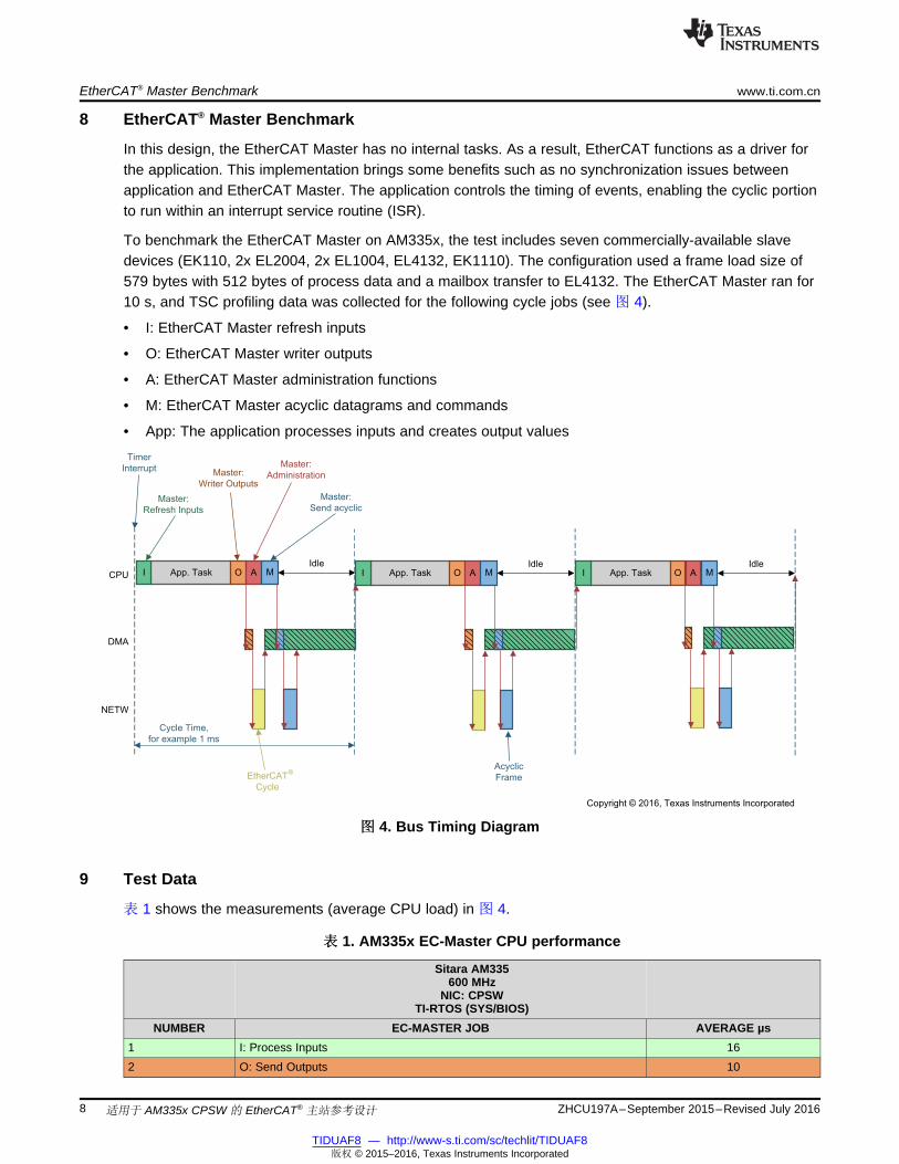
8 EtherCAT® Master Benchmark
In this design, the EtherCAT Master has no internal tasks. As a result, EtherCAT functions as a driver forthe application. This implementation brings some benefits such as no synchronization issues betweenapplication and EtherCAT Master. The application controls the timing of events, enabling the cyclic portionto run within an interrupt service routine (ISR).
To benchmark the EtherCAT Master on AM335x, the test includes seven commercially-available slavedevices (EK110, 2x EL2004, 2x EL1004, EL4132, EK1110). The configuration used a frame load size of579 bytes with 512 bytes of process data and a mailbox transfer to EL4132. The EtherCAT Master ran for10 s, and TSC profiling data was collected for the following cycle jobs (see 图 4).
• I: EtherCAT Master refresh inputs
• O: EtherCAT Master writer outputs
• A: EtherCAT Master administration functions
• M: EtherCAT Master acyclic datagrams and commands
• App: The application processes inputs and creates output values
图图 4. Bus Timing Diagram
9 Test Data
表 1 shows the measurements (average CPU load) in 图 4.
表表 1. AM335x EC-Master CPU performance
Sitara AM335600 MHz
NIC: CPSWTI-RTOS (SYS/BIOS)
NUMBER EC-MASTER JOB AVERAGE µs1 I: Process Inputs 162 O: Send Outputs 10

www.ti.com.cn Test Data
9ZHCU197A–September 2015–Revised July 2016
TIDUAF8 — http://www-s.ti.com/sc/techlit/TIDUAF8版权 © 2015–2016, Texas Instruments Incorporated
适用于 AM335x CPSW 的 EtherCAT® 主站参考设计
表表 1. AM335x EC-Master CPU performance (continued)Sitara AM335
600 MHzNIC: CPSW
TI-RTOS (SYS/BIOS)NUMBER EC-MASTER JOB AVERAGE µs
3 A: Administration 94 M: Send Acyclic Frame 4
Total CPU Time 39

Design Files www.ti.com.cn
10 ZHCU197A–September 2015–Revised July 2016
TIDUAF8 — http://www-s.ti.com/sc/techlit/TIDUAF8版权 © 2015–2016, Texas Instruments Incorporated
适用于 AM335x CPSW 的 EtherCAT® 主站参考设计
10 Design Files
10.1 Bill of Materials
To download the bill of materials (BOM), see the design files at TIDEP0043.
10.2 Software Files
To download the software files, see the design files at the TIDEP0043.
11 References
1. EtherCAT.org, Technical Introduction and Overview, (EtherCAT)2. Texas Instruments, EtherCAT ® on Sitara ™ Processors, White Paper (SPRY187)
11.1 商商标标
ARM, Cortex are registered trademarks of ARM Limited.EtherCAT, TwinCAT are registered trademarks of Beckhoff Automation GmbH & Co. KG.Linux、 is a registered trademark of Linus Torvalds.Windows is a registered trademark of Microsoft Corporation.QNX is a trademark of QNX Software Systems Limited.VxWorks is a registered trademark of Wind River.All other trademarks are the property of their respective owners.
12 About the Author
PAULA CARRILLO is a software engineer for the Embedded Processing group at TI. She obtained herMSEE from Florida Atlantic University and her Bachelor's Degree at Javeriana University, Colombia. Sincejoining TI in 2009, Paula has been working on different SoC and multicore DSP platforms developingapplications for high-performance video codecs, synthetic aperture radar (SAR), and industrialcommunication protocols.
13 About the Author—acontis technologies
STEFAN ZINTGRAF graduated as a Software Engineer in 1987 and began working as software engineerin Sulzer and LP Elektronik. After several years working as team leader in LP Elektronik he co-foundedacontis technologies GmbH in 2001, working as general manager. Stefan took over acontis’ EtherCATdevelopment activities in 2005 after being responsible for the acontis Windows® real-time products. He isalso responsible for the fast growing EtherCAT market in Asia in worldwide sales activities.

www.ti.com.cn 修订历史记录
11ZHCU197A–September 2015–Revised July 2016
TIDUAF8 — http://www-s.ti.com/sc/techlit/TIDUAF8版权 © 2015–2016, Texas Instruments Incorporated
Revision History
修修订订历历史史记记录录注:之前版本的页码可能与当前版本有所不同。
Changes from Original (September 2015) to A Revision ............................................................................................... Page
• Updated Hardware Subsection .......................................................................................................... 5• Updated Software Section................................................................................................................ 5• Updated acontis EC-Master from version 22.7.2.12 to 2.9 .......................................................................... 5• Updated CCS version from 6.0.0.00040 to 6.1.3 ..................................................................................... 5• Updated the instructions in Preparing the Application Section...................................................................... 5• Updated Running the Application Section ............................................................................................. 6• Updated Troubleshooting Section ..................................................................................................... 16

www.ti.com.cn
12 ZHCU197A–September 2015–Revised July 2016
TIDUAF8 — http://www-s.ti.com/sc/techlit/TIDUAF8版权 © 2015–2016, Texas Instruments Incorporated
AM437x Running EtherCAT Slave
附附录录 A AM437x Running EtherCAT Slave
A.1 Preparing the SD Card
Prepare the SD card by file allocation table (FAT) formatting it as follows:1. Ensure the HP USB disk storage format tool v2.0.6 is portable2. Run the HP USB disk storage format tool v2.0.6 as portable executable. The executable detects the
SD card that is plugged into the reader. If undetected, direct the executable to the new disk.3. Choose FAT32 if the SD card is greater than 4GB. If not, use FAT4. Click the Start button
注注: After formatting, the card can be populated by the files.
5. Install the ISDK prebuilt binaries (Industrial SDK 2.1.0.1)6. Copy MLO from
<Installation_path>\sysbios_ind_sdk_prebuilt_02_01_00_01\Bootloader\SD\am437x_release to the SDcard
7. Copy the EtherCAT Slave application from<Installation_path>\sysbios_ind_sdk_prebuilt_02_01_00_01\ethercat_slave\am437x_release
8. Connect the Ethernet cable to the ICCS port J69. Use Wireshark to test the ecat (EtherCAT) packets
Alternatively, use an EtherCAT Master, such as TwinCAT®, to test master-to-slave connectivity
For details using TwinCAT with TI IDK boards, see the user guide at wiki.ti.com.

www.ti.com.cn
13ZHCU197A–September 2015–Revised July 2016
TIDUAF8 — http://www-s.ti.com/sc/techlit/TIDUAF8版权 © 2015–2016, Texas Instruments Incorporated
acontis EC-Engineer Tool for Creating an .ENI File
附附录录 B acontis EC-Engineer Tool for Creating an .ENI File
1. Register for a free evaluation version at www.acontis.com2. Install the EC-Engineer tool on the PC3. Connect the EtherCAT slave to the computer (if using the AM437x, connect the Ethernet cable to J6)4. Open the EC-Engineer tool5. Select Online Configuration6. Select the EtherCAT Master unit (Class A) as the master unit7. Click the OK button8. Select 2000 as the Cycle Time (µs)9. Select the desired network adapter as the slave that is connected to the local system.
注注: If using the AM437x as the slave, add TI’s IDK.xml to the ESI manager as follows:• Open the ESI manager• Add the IDK.xml file• Browse to
<Installation_path>\sysbios_ind_sdk_2.1.0.1\sdk\examples\ethercat_slave\esi\TiEtherCATLib.xml
• Open the file• Navigate to the Network option• Click Scan EtherCAT Network• Click Export ENI after the slaves are found
Selecting Export ENI exports eni.xml.

www.ti.com.cn
14 ZHCU197A–September 2015–Revised July 2016
TIDUAF8 — http://www-s.ti.com/sc/techlit/TIDUAF8版权 © 2015–2016, Texas Instruments Incorporated
Application Console Output
附附录录 C Application Console Output
TI Industrial SDK Version - IASDK 1.1.0.8
Device name : AM3359
Chip Revision : AM335x ES1.2 [PG2.1]
SYS/BIOS EcMaster Sample application running on ICE V2
Full command line: -auxclk 2000 -v 2 -t 100000 -perf -cpsw 1 1 1 m 1 1
Run demo now with cycle time 2000 usec Using AuxClock
==========================
Initialize EtherCAT Master
==========================
EC-Master V2.7.2.12 (Eval) for SYSBIOS Copyright acontis technologies GmbH @ 2015
CPSW INF: Port 1, Prio 1, Flags [Polling] [Master], MAC 00:00:00:00:00:01
CPSW INF: CPSW3G found. CPSW INF: HW-Id: 0x0019, RTL: 0, Major: 1, Minor: 0xc
CPSW INF: PHY found. Id=0x2000a211
CPSW INF: Restart PHY auto negotiation
CPSW INF: PHY auto negotiation completed
Evaluation Version, stop sending ethernet frames after 60 minutes!
PDI Watchdog expired - Slave Slave_1001 [TIESC-002]: - EtherCAT address=1001
Bus scan successful - 1 slaves found
******************************************************************************
Number : 0
Vendor ID : 0xE000059D = ----
Product Code: 0x54490002 = Unknown
Revision : 0x00000001 Serial Number: 0
ESC Type : TI Sitara (0x90) Revision: 2 Build: 947
Bus AutoInc Address: 0 (0x0)
Bus Station Address: 1001 (0x3e9)
Bus Alias Address : 0000 (0x0)
Connection at Port 0: yes Port 1: no Port 2: no Port 3: no
SlaveID at Port 0: 65536 Port 1: -1 Port 2: -1 Port 3: -1
Config Station Address: 1001 (0x3e9)

www.ti.com.cn 附录 C
15ZHCU197A–September 2015–Revised July 2016
TIDUAF8 — http://www-s.ti.com/sc/techlit/TIDUAF8版权 © 2015–2016, Texas Instruments Incorporated
Application Console Output
PD IN Byte.Bit offset: 0.0 Size: 32 bits
PD OUT Byte.Bit offset: 0.0 Size: 32 bits
EtherCAT network adapter MAC: 00-00-00-00-00-01
=====================
Start EtherCAT Master
=====================
Master state changed from <UNKNOWN> to <INIT>
Master state changed from <INIT> to <PREOP>
Master state changed from <PREOP> to <SAFEOP>
Master state changed from <SAFEOP> to <OP>
Job times during startup <INIT> to <OP>:
================================================================
PerfMsmt 'JOB_ProcessAllRxFrames' (avg/max) [usec]: 29.6/ 91.4
PerfMsmt 'JOB_SendAllCycFrames ' (avg/max) [usec]: 18.2/ 36.5
PerfMsmt 'JOB_MasterTimer ' (avg/max) [usec]: 50.7/263.0
PerfMsmt 'JOB_SendAcycFrames ' (avg/max) [usec]: 21.3/ 64.4
PerfMsmt 'Cycle Time ' (avg/max) [usec]: 1624.0/2011.7
PerfMsmt 'myAppWorkPd ' (avg/max) [usec]: 1.7/ 5.8
================================================================
PerfMsmt 'JOB_ProcessAllRxFrames' (avg/max) [usec]: 32.9/ 48.4
PerfMsmt 'JOB_SendAllCycFrames ' (avg/max) [usec]: 30.6/ 39.2
PerfMsmt 'JOB_MasterTimer ' (avg/max) [usec]: 52.3/ 61.5
PerfMsmt 'JOB_SendAcycFrames ' (avg/max) [usec]: 7.0/ 15.9
PerfMsmt 'Cycle Time ' (avg/max) [usec]: 1998.1/2014.2
PerfMsmt 'myAppWorkPd ' (avg/max) [usec]: 2.2/ 9.0

www.ti.com.cn
16 ZHCU197A–September 2015–Revised July 2016
TIDUAF8 — http://www-s.ti.com/sc/techlit/TIDUAF8版权 © 2015–2016, Texas Instruments Incorporated
Troubleshooting
附附录录 D Troubleshooting
If the code hangs while reading PHY register MDIO, add the following line of code in main.c:GPIOInit();UTILsSetBoardType(3); //Added to fix board type to ICEv2s_boardType = UTILsGetBoardType();s_uartInstance = InitUart(s_boardType)
If the following error is printed in the console, the SPI likely preflashed.001181 : CPSW ERR: mdio ACK missing001181 : CPSW INF: mdio ref 2 error001181 : CPSW ERR: PHY initialization failed
The two solutions to this error are:
• Change the boot jumper to NOR Pin 1 and 2 shorted on J5, or
• Erase SPI flash
– For assistance erasing flash memory, see wiki.ti.com
For additional troubleshooting, refer to section 4.2 Error Codes in Acontis EC-Master Stack Class BVersion 2.7 Document by navigating to<ECmaster_installation_path>\Acontis_EC_master\EC_Master_Sysbios_SDK_Eval\Doc.
Users should also refer to AM335 Sysbios User Guide and Getting Started Guide by navigating to</ASDK_path>\am335x_sysbios_ind_sdk_1.1.0.8\sdk\docs.

IMPORTANT NOTICE有有关关 TI 设设计计信信息息和和资资源源的的重重要要通通知知
德州仪器 (TI) 公司提供的技术、应用或其他设计建议、服务或信息,包括但不限于与评估模块有关的参考设计和材料(总称“TI 资源”),旨在帮助设计人员开发整合了 TI 产品的 应用; 如果您(个人,或如果是代表贵公司,则为贵公司)以任何方式下载、访问或使用了任何特定的TI 资源,即表示贵方同意仅为该等目标,按照本通知的条款进行使用。TI 所提供的 TI 资源,并未扩大或以其他方式修改 TI 对 TI 产品的公开适用的质保及质保免责声明;也未导致 TI 承担任何额外的义务或责任。TI 有权对其 TI 资源进行纠正、增强、改进和其他修改。您理解并同意,在设计应用时应自行实施独立的分析、评价和 判断, 且应全权负责并确保 应用的安全性, 以及您的 应用 (包括应用中使用的所有 TI 产品))应符合所有适用的法律法规及其他相关要求。你就您的 应用声明,您具备制订和实施下列保障措施所需的一切必要专业知识,能够 (1) 预见故障的危险后果,(2) 监视故障及其后果,以及 (3) 降低可能导致危险的故障几率并采取适当措施。您同意,在使用或分发包含 TI 产品的任何 应用前, 您将彻底测试该等 应用 和该等应用所用 TI 产品的 功能。除特定 TI 资源的公开文档中明确列出的测试外,TI 未进行任何其他测试。您只有在为开发包含该等 TI 资源所列 TI 产品的 应用时, 才被授权使用、复制和修改任何相关单项 TI 资源。但并未依据禁止反言原则或其他法理授予您任何TI知识产权的任何其他明示或默示的许可,也未授予您 TI 或第三方的任何技术或知识产权的许可,该等产权包括但不限于任何专利权、版权、屏蔽作品权或与使用TI产品或服务的任何整合、机器制作、流程相关的其他知识产权。涉及或参考了第三方产品或服务的信息不构成使用此类产品或服务的许可或与其相关的保证或认可。使用 TI 资源可能需要您向第三方获得对该等第三方专利或其他知识产权的许可。TI 资源系“按原样”提供。TI 兹免除对 TI 资源及其使用作出所有其他明确或默认的保证或陈述,包括但不限于对准确性或完整性、产权保证、无屡发故障保证,以及适销性、适合特定用途和不侵犯任何第三方知识产权的任何默认保证。TI 不负责任何申索,包括但不限于因组合产品所致或与之有关的申索,也不为您辩护或赔偿,即使该等产品组合已列于 TI 资源或其他地方。对因 TI 资源或其使用引起或与之有关的任何实际的、直接的、特殊的、附带的、间接的、惩罚性的、偶发的、从属或惩戒性损害赔偿,不管TI 是否获悉可能会产生上述损害赔偿,TI 概不负责。您同意向 TI 及其代表全额赔偿因您不遵守本通知条款和条件而引起的任何损害、费用、损失和/或责任。本通知适用于 TI 资源。另有其他条款适用于某些类型的材料、TI 产品和服务的使用和采购。这些条款包括但不限于适用于 TI 的半导体产品(http://www.ti.com/sc/docs/stdterms.htm)、评估模块和样品 (http://www.ti.com/sc/docs/sampterms.htm) 的标准条款。
邮寄地址:上海市浦东新区世纪大道 1568 号中建大厦 32 楼,邮政编码:200122Copyright © 2017 德州仪器半导体技术(上海)有限公司