thrusters thrust degradation in dp...
TRANSCRIPT

Thrusters
Thrust Degradation in DP OperationsDP Model Test of an Aframaz Shuttle Tanker – Methods
Results, Operations
Reinert Nordtveit - Teekay Corporation
Bjørn Nygård - Kongsberg Maritime AS
Egil Jullumstrø - MARINTEK
October 9-10, 2007Return to Session DirectoryReturn to Session Directory

T E E K A Y – T H E M A R I N E M I D S T R E A M C O M P A N Y ®
www.teekay.com
Dynamic Positioning Conference – Houston, 2007
Thrust Degradationin DP Operations
DP Model Test of an Aframax Shuttle Tanker
by
Reinert Nordtveit – Teekay CorporationBjørn Nygård – Kongsberg Maritime
Egil Jullumstrø - Marintek
Return to Session DirectoryReturn to Session Directory

2 www.teekay.com
DP model test of an IMO Class 2 Shuttle Tanker
Focus ono Thrust degradation effectso Environmental design criteriao DP performance and design evaluation
R&D project with the partners:Teekay, Kongsberg Maritime and Marintek
Introduction
Return to Session DirectoryReturn to Session Directory

3 www.teekay.com
• Transports more than 10 percent of the world’s seaborne oil• Operates more than 190 vessels / 41 DP shuttle tankers• Global organization / 17 countries / 6,300 employees• More than 19.000 cargo lifts carried out by shuttle tankers during the
past 25 years• Offshore loading using DP control is a safe and reliable operation• Continuous focus to improve design and operational excellence
Teekay Corporation
Return to Session DirectoryReturn to Session Directory

4 www.teekay.com
Project Incentive
Experience from operations in harsh weather conditions have shown indications of lower margins on the vessel’s station keeping performance than calculated by theoretical analyses such as DP capability plots
A lack of industrial practices on how thrust degradation effects and environmental design criteria are defined and incorporated in DPcapability analyses in general has been identified
The main drivers are to further improve the safety, efficiency and regularity of offshore loading operations
Return to Session DirectoryReturn to Session Directory

5 www.teekay.com
Dynamic Positioning - Force Balance Exercise
Propeller forces counteract drifting forces
Propeller forces delivered by
Main propellers and high lift ruddersTunnel and azimuth thrusters
Return to Session DirectoryReturn to Session Directory

6 www.teekay.com
Dynamic Positioning - Force Balance Exercise
Propeller forces counteract drifting forces
Drifting forces determined by
Environmental conditionsVessel’s main particulars
Return to Session DirectoryReturn to Session Directory
7 www.teekay.com
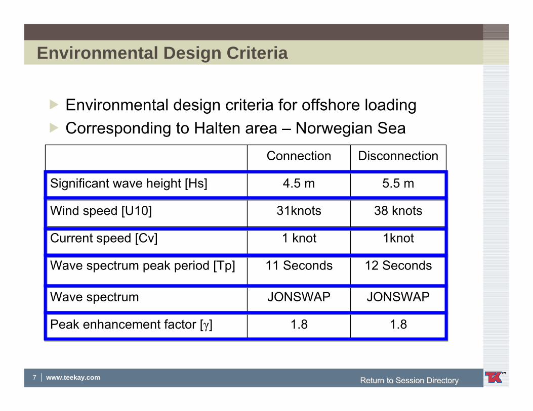
Environmental Design Criteria
Environmental design criteria for offshore loadingCorresponding to Halten area – Norwegian Sea
1.81.8Peak enhancement factor [γ]
JONSWAPJONSWAPWave spectrum
12 Seconds11 SecondsWave spectrum peak period [Tp]
1knot1 knotCurrent speed [Cv]
38 knots31knotsWind speed [U10]
5.5 m4.5 mSignificant wave height [Hs]
DisconnectionConnection
Return to Session DirectoryReturn to Session Directory

8 www.teekay.com
Thrust and Propeller Forces
Nominal thrust – Thrust degradation = Thrust available
Thrust degradation
Thrust degradation affected by
o thruster-hull interactions (Coanda)o thruster-thruster interactionso sea current o wave effectso ship motionso thruster ventilation
nomTT
=τ
Return to Session DirectoryReturn to Session Directory

9 www.teekay.com
Model and Thruster Configuration
Two aft ships; single and twin screw
Interchangeable forebody
Model scale 1:25, L ≈ 10 m , Displ. ≈ 6.9 mt
Return to Session DirectoryReturn to Session Directory

10 www.teekay.com
Model and Thruster Configuration
Return to Session DirectoryReturn to Session Directory

11 www.teekay.com
Thrust Loss Model Test
Measurement of thrust degradation forMain propellers and rudders - single and twin screwTunnel thrusters - fwd and aftAzimuth thrusters – fwd and aft
Loading conditionsBallastLoaded
Environmental ConditionsCalm waterOffshore loading criteria; connection and disconnectionCorresponding to Halten Area in the Norwegian Sea
Return to Session DirectoryReturn to Session Directory

12 www.teekay.com
Thrust Loss Model Test
Thrust degradation measurement program comprised the following
Open water characteristics for all propeller and thruster units
Thruster – thruster interactions
Thruster – hull interactions
Thruster – rudder interactions
Tunnel thruster losses
Thrust degradation due to current
Thrust degradation due to waves
Thrust degradation due to ventilation
Return to Session DirectoryReturn to Session Directory

13 www.teekay.com
Thrust Loss Model Test - Results
Thrust reduction coefficients - bow azimuth thruster
0.00
0.25
0.50
0.75
1.00
0 60 120 180
Thrust angle [deg]
[-]
Ballast condition
Loaded condition
Thrust degradation measurements for bow azimuth thruster
Return to Session DirectoryReturn to Session Directory

14 www.teekay.com
Thrust Loss Model Test - ResultsThrust degradation measurement for aft azimuth thruster
Thrust reduction coefficients - aft azimuth thruster
0.00
0.25
0.50
0.75
1.00
0.0 60.0 120.0 180.0
Thrust angle [deg]
[-]
Ballast condition
Loaded condition
Return to Session DirectoryReturn to Session Directory

15 www.teekay.com
Thrust Loss Model Test - Results
Thrust degradation measurement for main propeller and tunnel thrusters
0.800.65Tunnel thruster - aft
0.800.65Tunnel thruster – bow
0.870.75Main propeller twin-screw
0.850.75Main propellersingle-screw
Loaded conditionBallast condition
Thrust degradation coefficients –Main propeller and tunnel thrusters
Return to Session DirectoryReturn to Session Directory

16 www.teekay.com
DP Model Test
Marintek Ocean Basin, 80m x 50m x 10m“Off-the-shelf” DP softwareNorth Sea environmental conditionsBallast and loaded conditionsIntact and failure modeVarious power settings for thrustersTest duration; 1 hour full scale time / 12 minutes model scale time
Return to Session DirectoryReturn to Session Directory

17 www.teekay.com
DP Model Test
Return to Session DirectoryReturn to Session Directory

18 www.teekay.com
DP Model Test - Results
0 500 1000 1500 2000 2500 3000 350040
60
80
Time (s)
Radial distance to buoy (m)
1hour DP in FAILURE MODE
MARINTEK, 18:00 26-Sep-2007
T:\Prosjekt\P53 Marine Vehicles\530346 Teekay Aframax IMO DP2 Shuttle Tanker\Matlab\plot_TOT_dist_530233
Run # 620 :: LOADED HS5.5 TP12 UC1 UW38Run # 320 :: BALLAST IRR H5.5 TP12 UC1 UW38
Return to Session DirectoryReturn to Session Directory

19 www.teekay.com
DP Capability PlotStatic force balanceAuto position mode is assumedTandem offshore loading is a “weather vane” operationSector around the bow of relevance for shuttle tankers Thrust degradation calculation included in StatCap
Thrust reduction coefficients - bow azimuth thruster
0.00
0.25
0.50
0.75
1.00
0.0 60.0 120.0 180.0
Thrust angle [deg]
[-]
CalculationsMeasurementsBarred azimuth sectorAverage (from measurements)
Return to Session DirectoryReturn to Session Directory

20 www.teekay.com
DP Capability Plot - ExampleWorst case single failure for a DP2 single screw shuttle tankerNorth sea environmental design conditions - ballast
Plot 1: Thrust degradation not included Plot 2: Thrust degradation included
Return to Session DirectoryReturn to Session Directory

21 www.teekay.com
Conclusions
Thrust degradation effects are of significant importance for all types of DP vessels
Thrust degradation effects should be accounted for in design andoperation of DP vessels
Magnitude depends on vessel design, operation and environmental conditions
Thrust degradation calculations have been included in software for DP capability analysis; KM StatCap
Calculations correspond reasonably well with model test measurements for a shuttle tanker
Results from DP capability analysis (capability plot) correspondwell with shuttle tanker operational experience
Return to Session DirectoryReturn to Session Directory

22 www.teekay.com
Questions ?Questions ?Thank you!Thank you!
Dynamic Positioning Conference – Houston, 2007
Return to Session DirectoryReturn to Session Directory