throughput and delay analysis of truncated …ajib_w/index_fichiers/publi_conf/ajib_iwcmc... ·...
TRANSCRIPT

Throughput and Delay Analysis of Truncated
Cooperative ARQ Protocols using DSTC
Marwen Bouanen
Department of Computer Science
Université du Québec à Montréal
Montréal, Québec, Canada
Wessam Ajib
Department of Computer Science
Université du Québec à Montréal
Montréal, Québec, Canada
Hatem Boujemaa
TECHTRA, SUPCOM
University of Carthage
Tunis, Tunisia
Abstract—In this paper, we evaluate the throughput and the
packet total transmission delay for cooperative truncated
Automatic Repeat Request (ARQ) using distributed space-
time codes, where relays use either Decode-And-Forward
(DF) or Amplify-and-Forward (AF) relaying. In this scheme,
relays are involved in the retransmission only when the
destination receives erroneously the packet. Both source and
relays make use of an orthogonal space time block code. For
the DF mode, relays are selected after a verification by the
cyclic redundancy check (CRC) sequence. However, for the
AF mode, all relays are involved in the retransmission. We
show that the proposed design can significantly improve
performances in terms of throughput and total transmission
delay.
Keywords-Cooperative communications, HARQ, Delay analysis.
I. INTRODUCTION
The employment of MIMO technology may bring spatial
diversity and therefore a significant improvement of the
channel capacity. However, in practice, nodes are constrained
by their limited size so that the implementation of multiple
antennas is difficult. As a solution, a novel approach called
"Cooperative Communications" has been introduced to
overcome such limitations. The solution consists in using relay
nodes as a virtual antenna array to help the source node in
transmitting the information. Such an approach allows to
realize cooperative diversity.
Trying to benefit from cooperative communications,
researchers have introduced many cooperative protocols such
as Amplify-and-forward (AF), Decode-and-forward (DF), and
selective relaying [1]. Other important works include
distributed space-time coding (DSTC) which are shown to
improve the bandwidth efficiency of cooperative
communications [2].1
On the other hand, many works have proposed ARQ
protocol at the link layer to overcome the fading nature of
wireless channels where CRC is a common tool to decide
whether the packet has been correctly received by the
destination node or not. Moreover, the maximum number of
This work was supported by Qatar National Research Fund under Grant
NPRP 08-577-2-241 and NSERC-DG
retransmissions is often limited. Such a variant of ARQ is
called “truncated ARQ”.
As a combination of the previous techniques, cooperative
ARQ protocol has been proposed by combining cooperative
diversity and truncated ARQ. In such protocol, relay nodes
cooperation can be implemented via a DSTC. In fact, studies
have shown that cooperative ARQ can achieve significant
throughput gains [3]. It has been shown that combination of
cooperative diversity and truncated ARQ can greatly improve
the system throughput compared to the conventional truncated
ARQ scheme. Authors of [3] aimed to maximize the
throughput by optimizing the packet length and modulation
level.
Other studies have treated cooperative ARQ from a
transmission delay point of view [4]. The author has evaluated
the delay experienced by Poisson arriving packets for a
specific variant of cooperative truncated ARQ called
cooperative hybrid ARQ with opportunistic relaying. The
results of this work indicate a significant improvement of the
packet waiting time and sojourn time when compared with
pure truncated ARQ protocol. Delays and throughput have
been studied in these mentioned works since they are
considered as important performance parameters [5].
The novelty compared to the mentioned works is that we
optimize the performance with respect to a variable which has
never been treated before : The number of available relays.
Moreover, to the best of our knowledge, studies have not yet
treated the case where the system has to handle the two
following performance metrics: throughput and total
transmission delay. In this paper, we propose a cross-layer
design between the physical layer where we use a cooperative
diversity, and the link layer where we exploit truncated ARQ.
In this scheme, we assume Q idle nodes around the source.
The source transmits a packet to the destination node. After
verifying its CRC bits, the destination decides whether the
received packet is correct or not. If the packet is erroneously
received, a retransmission process is launched, and the source
and relays use an orthogonal space-time code. Moreover,
relays can operate according to two relaying modes: DF and
AF. In DF relaying, only the relays having correctly decoded
the CRC are selected among Q nodes. Whereas, for AF mode,
all the Q relays participate in the retransmission process.
978-1-4577-9538-2/11/$26.00 ©2011 IEEE 731

In the present paper we concentrate on the performance
parameters at the link layer. The throughput and total
transmission delay are given for both DF and AF relying
modes. It will be shown that, for good source-relay channels,
using DF at relays outperforms the AF relaying.
This paper is organized as follows. Section II describes the
system model. Sections III and IV are dedicated to derive the
expressions of throughput and delay. Numerical and
simulation results are given in section V. Finally, section VI
summarizes and concludes this paper.
Notations: The subscripts , and stand for
transposition, Hermitian conjugation and element-wise
conjugation, respectively. The expectation operation is
denoted by .
Fig.1. Wireless relay network including one source, Q idle relays, and
one destination.
II. SYSTEM MODEL
We consider a network composed of a source node S, a
destination node D and K relays. It is assumed that each node
is equipped with a single antenna. Among these relays, we
assume Q idle relays to be available for the source when
transmitting a packet (see Fig.1). In a nutshell, our proposed
scheme is divided into two phases. In the first phase, the
source node transmits a packet to which a C-bit CRC is added.
Once the packet is detected at the destination, a CRC
verification is accomplished so that an acknowledgment is sent
back to the source node. In the case where the destination
detects correctly the packet, the acknowledgment is said to be
positive (ACK) and the source transmits the next packet.
Otherwise, a negative acknowledgment (NACK) is sent back
asking the source for retransmitting the packet. At that time,
the second phase starts and the Q candidate relays participate
in a retransmission process according to one of the two
relaying modes:
Decode and Forward (DF): the source node and the
concerned relays will cooperate in order to retransmit the
packet by implementing a suitable distributed orthogonal
space-time block code OSTBC. In fact, among Q relays,
the ν selected relays which are involved in the
retransmission process are those that have successfully
decoded the transmitted packet. This adaptability in the
cooperation process allows us to avoid error propagation.
Moreover, this scheme provides cooperative diversity.
That is why, an important improvement of the link layer
performance from its both sides –throughput and
transmission delay- is expected.
Amplify and Forward (AF): here, the relay nodes do not
verify the CRC so that all of the Q candidate relays are
selected to participate in the phase of retransmission,
i.e. ν = Q. The cooperation is realized by utilizing a
(Q+1)-transmit-1-receive OSTBC.
Retransmission is stopped only when the packet is correctly
detected at the destination or when the number of
retransmissions reaches its maximum . It is assumed in
the rest of the paper, that the source-to-destination, source-to-
relay and relay-to-destination links are characterized by quasi-
static Rayleigh distributed flat fading channels. The source
transmits a packet s = , consisting of L M-QAM
modulated symbols to the destination, where L is the packet
length. It is assumed that = 1. This means that
from time to , the transmitted signals are , …,
where is the average transmitted energy per symbol.
The L 1 received signals at the destination and the r-th relay
are given respectively by
(1)
and (2)
where , …, are L 1 independent identically distributed
(i.i.d.), zero-mean complex Gaussian random variables with
variance N0. Under the assumption that each source-relay link
undergoes independent Rayleigh process, , …, and are
i.i.d. complex Gaussian random variables with zero mean and
variance and
, respectively.
In the case where the destination detects erroneously the
packet, the ν relays cooperate with the source node by
transmitting linear transformations of and where
If DF is the relaying mode
If AF is the relaying mode
The implementation of the DSTC is presented at the
destination as follows
(3)
where the L 1 additive noise w and fading coefficients
, …, are i.i.d. complex zero-mean Gaussian random
variables with variance N0 and , respectively. and ,
i = 0,..., , are the result of the representation of the
i-th column of the L (ν+1) space time code matrix S
as . On the other hand, is the amplification
factor at the relay which is given by
1 If DF is the relaying mode
If AF is the relaying mode
where is the transmitted energy per symbol by the relay.
In this paper, it is assumed that the Q relays are nearby
Source Destination
Rν
R1
D
1
𝑄
⋮ ⋮
𝑣
𝑣1 1
0 𝑣0
Q
𝑤1
𝑤Q
RQ
𝑣Q
⋮ ⋮
S
𝑤
D
Destination
732

the source node so that the large scale fading of the
relay-destination channels and the source-destination channels
are almost the same, i.e. =
. Let and be the
average SNR per symbol of the transmission phase and
retransmission, respectively. Furthermore, we denote by
and the block error probability of the
transmission and retransmission, respectively. The symbol
error probabilities (SEP) of transmission and retransmission
are denoted and , respectively.
III. THROUGHPUT ANALYSIS
In this section, we derive the throughput realized by the
proposed scheme according to the DF and AF modes.
Let C be the number of CRC redundancy bits added
to the packet and L its length. The adopted modulation is
M-QAM with b = log2(M). Here, the retransmission is only
done when the destination erroneously detects the packet. The
retransmission is stopped when the packet is correctly received
at the destination or the number of retransmission reaches
its maximum .
A. Throughput of the AF relaying mode
The throughput of the AF relaying mode is given by
(4)
where is the packet successful rate which is given by
(5)
while is a random variable representing the total number
of transmissions of a given packet and is the average
number of retransmissions per packet given by
(6)
𝑄
𝑥
𝑄
where (7)
and (8)
In (6), 𝑄 is the rate of a (Q+1)-symbol STBC
where . By assuming a Rayleigh flat fading channel
over the source-destination link and a M-QAM modulation, the
expression of can be deduced from [6] as follows
(9)
where . For the retransmission phase, the
system can be considered as a (Q+1)-transmit-1-receive
distributed OSTBC with M-QAM modulation over Rayleigh-
fading channels. As a result, from [7], the symbol error
probability according to the moment generating
function (MGF) approach can be approximated as follows
(10)
where
(11)
(12)
𝑄
(13)
and
𝑄
(14)
is the exponential integral function,
and
.
B. Throughput of the DF relaying mode
For this relaying mode, the nodes that are involved in the
retransmission phase are those which have correctly detected
the CRC. Therefore, the number of relay nodes is not fixed.
The throughput expression of the DF relaying mode is given
by
(15)
where and are the packet successful probability
and the average number of retransmissions per packet,
respectively. Their explicit expressions are given by
(16)
and
𝑄
(17)
where given by
(18)
for j=0,…,Q.
In (17), is the block error probability when
j relays are involved in the retransmission. is the
probability that j relays detect correctly CRC and it is given by
𝑄
(19)
733
where j = 0,…, Q. is the block error probability
of the S-R channel which is given by
, where, is the symbol error
probability of the S-R channel.
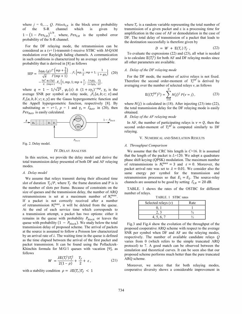
For the DF relaying mode, the retransmission can be
considered as a (ν+1)-transmit-1-receive STBC with M-QAM
modulation over Rayleigh fading channels. A communication
in such conditions is characterized by an average symbol error
probability that is derived in [8] as follows
. 2
(20)
where is the
average SNR per symbol at relay node, 2 𝑥 and
𝑥 𝑦 are the Gauss hypergeometric function and
the Appell hypergeometric function, respectively [8]. By
substituting m = ν+1, p = 1 and in (20), then
is easily calculated.
Fig. 2. Delay model.
IV. DELAY ANALYSIS
In this section, we provide the delay model and derive the
total transmission delay presented of both DF and AF relaying
modes.
A. Delay model
We assume that relays transmit during their allocated time
slot of duration , where the frame duration and P is is
the number of slots per frame. Because of constraints on the
size of queues and the transmission delay, the number of ARQ
retransmissions is set at a maximum number of .
If a packet is not correctly received after a number
of retransmission , it will be deleted from the queue.
At the end of each service time which corresponds to
a transmission attempt, a packet has two options: either it
remains in the queue with probability or leaves the
queue with probability . We study below the total
transmission delay of proposed scheme. The arrival of packets
at the source is assumed to follow a Poisson law characterized
by an arrival rate of λ. The waiting time in the queue is defined
as the time elapsed between the arrival of the first packet and
packet transmission. It can be found using the Pollackzek-
Khinchin formula for M/G/1 queues with vacation [9], as
follows
(21)
with a stability condition
where is a random variable representing the total number of
transmission of a given packet and ε is a processing time for
amplification in the case of AF or demodulation in the case of
DF. The total delay of transmission of a packet that leads to
the destination successfully is therefore given by
(22)
To evaluate the expressions (22) and (23), all what is needed
is to calculate for both AF and DF relaying modes since
all other parameters are available.
A. Delay of the DF relaying mode
For the DF mode, the number of active relays is not fixed.
Therefore the second order-moment of is derived by
averaging over the number of selected relays , as follows
𝑄
(23)
where is calculated in (18). After injecting (23) into (22),
the total transmission delay for the DF relaying mode is easily
obtained.
B. Delay of the AF relaying mode
In AF, the number of participating relays is 𝑄, then the
second order-moment of is computed similarly to DF
relaying.
V. NUMERICAL AND SIMULATION RESULTS
A. Throughput Comparison
We assume that the CRC bits length is C=16. It is assumed
that the length of the packet is L=120. We adopt a quadrature
phase shift keying (QPSK) modulation. The maximum number
of retransmissions is and . Moreover, the
packet arrival rate was set to . We consider also the
same energy per symbol for the transmission and
retransmission processes so that . The source-relay
channels are assumed to be good by setting dB.
TABLE. 1 shows the rates of the OSTBC for different
number of relays. TABLE. 1 STBC rates
Selected relays (ν) Rate
0, 1 1
2, 3 ¾
4, 5, 6, 7 ½
Fig.3 and Fig.4 show the evolution of the throughput of the
proposed cooperative ARQ scheme with respect to the average
SNR per symbol when DF and AF are the relaying modes,
respectively. The number of available candidate relays Q
varies from 0 (which refers to the simple truncated ARQ
protocol) to 7. A good match can be observed between the
simulation and theoretical curves. It can be seen also that our
proposed scheme performs much better than the pure truncated
ARQ scheme.
Moreover, we notice that for both relaying modes,
cooperative diversity shows a considerable improvement in
pN . . . p2 p1
𝝀
1 Active
Idle
734

terms of throughput. Here, the source-relays channels are
good. That’s why, cooperative diversity gain can be fully
exploited to improve the SEP of the retransmission process so
additional throughput gains can be expected to be achieved
over the pure truncated ARQ scheme. It should be noticed that
starting from specific high values of SNR, a decrease of the
throughput is noticed for curves corresponding to Q = 5 and
Q = 7 when compared with curves Q {0, 1, 2, 3}. This
behavior is due to the fact that the STBC does not have a full
rate.
We provide Fig. 5 to conclude about the throughput
performance for the DF and AF modes. This figure draws the
throughput efficiency versus the number of available relays Q.
It can be easily seen that combining ARQ protocol at link
layer and cooperative diversity, increases the throughput. For
DF relaying, we notice an increase of the throughput
efficiency from 0.02 bit/s/Hz for pure truncated ARQ (Q = 0),
to 0.55 bit/s/Hz for the Q = 7, when . From a
throughput point of view, it can be seen that DF relaying mode
outperforms AF. This is due to the adaptability of the source-
relay channels and the reduced number of used relays.
However, this improvement is at the price of more
functionalities to be implemented at the relay nodes.
Fig .5 shows that a convenient choice of Q (for instance :
Q = 5 for the curve SNR = 12 dB), allows us to optimize the
performance in terms of throughput.
B. Delay Comparison
Fig. 6 shows the total transmission delay with respect to the
number of available relays Q. We notice that DF relaying
offers better performance than AF relaying. Indeed, for the AF
relaying, both noise and useful signal are amplified. However,
the DF relaying presents larger computational complexity and
selection time than AF relaying. Thanks to the proposed cross-
layer design, it can be seen that by optimizing Q, the total
transmission delay can be minimized. Concerning the curve
where SNR = 12 dB in Fig .6, Q = 4 is the optimal number of
available relays that should be used to minimize the total
transmission delay. Moreover, we show that a good choice of
Q, helps to avoid an overuse of relays and thus a smaller
amount of signaling between relays is needed. The SNR in
Fig. 5 and 6 denotes the average SNR of the direct link which
is the same as that of the R-D link since the relays are close to
the source.
VI. CONCLUSION
In this work, we have evaluated the throughput and the total
transmission delay of the proposed cross-layer design that
combines ARQ at the link layer and cooperative diversity at
the physical layer. It has been shown that a great improvement
of the QoS in terms of throughput and the total transmission
delay has been witnessed. We have shown that the DF
relaying mode outperforms AF. It has been noticed also that
optimizing the number of available relays Q improves the
performance.
Fig. 3. Throughput of cooperative ARQ protocol using DF relaying
for 20 dB.
Fig. 4. Throughput of cooperative ARQ protocol using AF relaying
for 20 dB.
Fig. 5. Throughput efficiency versus the number of available relays
for = 20 dB.
Thro
ugh
put
eff
icie
ncy (
bit/s
/hz)
1.2
1 0.8
0.6
Q = 7 (Analytical)
Q = 7 (Simulation)
Q = 5 (Analytical)
Q = 5 (Simulation)
Q = 3 (Analytical)
Q = 3 (Simulation)
Q = 2 (Analytical)
Q = 2 (Simulation)
Q = 1 (Analytical)
Q = 1 (Simulation)
Q = 0 : Truncated ARQ (Analytical)
Q = 0 : Truncated ARQ (Simulation)
0.4
0.2
0
0 2 4 6 8 10 12 14 16 18 20 Es/No, dB
Th
rou
gh
put
eff
icie
ncy (
bit/s
/hz)
1.2
1 0.8
0.6
Q = 7 (Analytical)
Q = 7 (Simulation)
Q = 5 (Analytical)
Q = 5 (Simulation)
Q = 3 (Analytical)
Q = 3 (Simulation)
Q = 2 (Analytical)
Q = 2 (Simulation)
Q = 1 (Analytical)
Q = 1 (Simulation)
Q = 0 : Truncated ARQ (Analytical)
Q = 0 : Truncated ARQ (Simulation)
0.4
0.2
0
0 2 4 6 8 10 12 14 16 18 20 Es/No, dB
Thro
ugh
put
eff
icie
ncy (
bit/s
/hz)
1.2
1
0.8
0.6
Q = 7 (Analytical)
Q = 7 (Simulation)
Q = 5 (Analytical)
Q = 5 (Simulation)
Q = 3 (Analytical)
Q = 3 (Simulation)
Q = 2 (Analytical)
Q = 2 (Simulation)
Q = 1 (Analytical)
Q = 1 (Simulation)
Q = 0 : Truncated ARQ (Analytical)
Q = 0 : Truncated ARQ (Simulation)
0.4
0.2
0 0 2 4 6 8 10 12 14 16 18 20
SNR, dB
Thro
ugh
put
eff
icie
ncy (
bit/s
/hz)
1.2
1 0.8
0.6
Q = 7 (Analytical)
Q = 7 (Simulation)
Q = 5 (Analytical)
Q = 5 (Simulation)
Q = 3 (Analytical)
Q = 3 (Simulation)
Q = 2 (Analytical)
Q = 2 (Simulation)
Q = 1 (Analytical)
Q = 1 (Simulation)
Q = 0 : Truncated ARQ (Analytical)
Q = 0 : Truncated ARQ (Simulation)
0.4
0.2
0
0 2 4 6 8 10 12 14 16 18 20 Es/No, dB
Thro
ugh
put
eff
icie
ncy (
bit/s
/hz)
1.2
1 0.8
0.6
Q = 7 (Analytical)
Q = 7 (Simulation)
Q = 5 (Analytical)
Q = 5 (Simulation)
Q = 3 (Analytical)
Q = 3 (Simulation)
Q = 2 (Analytical)
Q = 2 (Simulation)
Q = 1 (Analytical)
Q = 1 (Simulation)
Q = 0 : Truncated ARQ (Analytical)
Q = 0 : Truncated ARQ (Simulation)
0.4
0.2
0
0 2 4 6 8 10 12 14 16 18 20 Es/No, dB
Th
rou
gh
put
eff
icie
ncy (
bit/s
/hz)
1.2
1
0.8
0.6
Q = 7 (Analytical)
Q = 7 (Simulation)
Q = 5 (Analytical)
Q = 5 (Simulation)
Q = 3 (Analytical)
Q = 3 (Simulation)
Q = 2 (Analytical)
Q = 2 (Simulation)
Q = 1 (Analytical)
Q = 1 (Simulation)
Q = 0 : Truncated ARQ (Analytical)
Q = 0 : Truncated ARQ (Simulation)
0.4
0.2
0 0 2 4 6 8 10 12 14 16 18 20
SNR, dB
0.7
0.6
0.5
0.4
0.3
0.2
0.1
0 0 1 2 3 4 5 6 7
Th
rou
gh
put
eff
icie
ncy (
bit/s
/hz)
1.2
1 0.8
0.6
Q = 7 (Analytical)
Q = 7 (Simulation)
Q = 5 (Analytical)
Q = 5 (Simulation)
Q = 3 (Analytical)
Q = 3 (Simulation)
Q = 2 (Analytical)
Q = 2 (Simulation)
Q = 1 (Analytical)
Q = 1 (Simulation)
Q = 0 : Truncated ARQ (Analytical)
Q = 0 : Truncated ARQ (Simulation)
0.4
0.2
0
0 2 4 6 8 10 12 14 16 18 20 Es/No, dB
0.7
DF with ΓR-D = 12 dB
DF with ΓR-D = 10 dB
0.6 DF with ΓR-D = 8 dB
AF with ΓR-D = 12 dB
AF with ΓR-D = 10 dB
0.5 AF with ΓR-D = 8 dB
0.4
0.3
0.2
0.1
0
0 1 2 3 4 5 6 7 Number of candidate relays Q
0.7
DF with ΓR-D = 12 dB
DF with ΓR-D = 10 dB
0.6 DF with ΓR-D = 8 dB
AF with ΓR-D = 12 dB
AF with ΓR-D = 10 dB
0.5 AF with ΓR-D = 8 dB
0.4
0.3
0.2
0.1
0
0 1 2 3 4 5 6 7 Number of candidate relays Q
SNR
SNR
SNR
0.7
DF with ΓR-D = 12 dB
DF with ΓR-D = 10 dB
0.6 DF with ΓR-D = 8 dB
AF with ΓR-D = 12 dB
AF with ΓR-D = 10 dB
0.5 AF with ΓR-D = 8 dB
0.4
0.3
0.2
0.1
0
0 1 2 3 4 5 6 7 Number of candidate relays Q
SNR
SNR
SNR
0.7
DF with ΓR-D = 12 dB
DF with ΓR-D = 10 dB
0.6 DF with ΓR-D = 8 dB
AF with ΓR-D = 12 dB
AF with ΓR-D = 10 dB
0.5 AF with ΓR-D = 8 dB
0.4
0.3
0.2
0.1
0
0 1 2 3 4 5 6 7 Number of candidate relays Q
To
tal tr
ansm
issio
n d
ela
y
6
SNR
= 12 dB
SR
SNR = 10 dB SR
SNR = 8 dB 5.5 SR
5
4.5
4
3.5
3
0 1 2 3 4 5 6 7 Number of candidate relays Q
0.7
DF with ΓR-D = 12 dB
DF with ΓR-D = 10 dB
0.6 DF with ΓR-D = 8 dB
AF with ΓR-D = 12 dB
AF with ΓR-D = 10 dB
0.5 AF with ΓR-D = 8 dB
0.4
0.3
0.2
0.1
0
0 1 2 3 4 5 6 7 Number of candidate relays Q
0.7
DF with ΓR-D = 12 dB
DF with ΓR-D = 10 dB
0.6 DF with ΓR-D = 8 dB
AF with ΓR-D = 12 dB
AF with ΓR-D = 10 dB
0.5 AF with ΓR-D = 8 dB
0.4
0.3
0.2
0.1
0
0 1 2 3 4 5 6 7 Number of candidate relays Q
SNR
SNR
SNR
0.7
DF with ΓR-D = 12 dB
DF with ΓR-D = 10 dB
0.6 DF with ΓR-D = 8 dB
AF with ΓR-D = 12 dB
AF with ΓR-D = 10 dB
0.5 AF with ΓR-D = 8 dB
0.4
0.3
0.2
0.1
0
0 1 2 3 4 5 6 7 Number of candidate relays Q
SNR
SNR
SNR
0.7
DF with ΓR-D = 12 dB
DF with ΓR-D = 10 dB
0.6 DF with ΓR-D = 8 dB
AF with ΓR-D = 12 dB
AF with ΓR-D = 10 dB
0.5 AF with ΓR-D = 8 dB
0.4
0.3
0.2
0.1
0
0 1 2 3 4 5 6 7 Number of candidate relays Q
0.7
DF with ΓR-D = 12 dB
DF with ΓR-D = 10 dB
0.6 DF with ΓR-D = 8 dB
AF with ΓR-D = 12 dB
AF with ΓR-D = 10 dB
0.5 AF with ΓR-D = 8 dB
0.4
0.3
0.2
0.1
0
0 1 2 3 4 5 6 7 Number of candidate relays Q
SNR
SNR
SNR
0.7
DF with ΓR-D = 12 dB
DF with ΓR-D = 10 dB
0.6 DF with ΓR-D = 8 dB
AF with ΓR-D = 12 dB
AF with ΓR-D = 10 dB
0.5 AF with ΓR-D = 8 dB
0.4
0.3
0.2
0.1
0
0 1 2 3 4 5 6 7 Number of candidate relays Q
SNR
SNR
SNR
0.7
DF with ΓR-D = 12 dB
DF with ΓR-D = 10 dB
0.6 DF with ΓR-D = 8 dB
AF with ΓR-D = 12 dB
AF with ΓR-D = 10 dB
0.5 AF with ΓR-D = 8 dB
0.4
0.3
0.2
0.1
0
0 1 2 3 4 5 6 7 Number of candidate relays Q
0.7
DF with ΓR-D = 12 dB
DF with ΓR-D = 10 dB
0.6 DF with ΓR-D = 8 dB
AF with ΓR-D = 12 dB
AF with ΓR-D = 10 dB
0.5 AF with ΓR-D = 8 dB
0.4
0.3
0.2
0.1
0
0 1 2 3 4 5 6 7 Number of candidate relays Q
SNR
SNR
SNR
0.7
DF with ΓR-D = 12 dB
DF with ΓR-D = 10 dB
0.6 DF with ΓR-D = 8 dB
AF with ΓR-D = 12 dB
AF with ΓR-D = 10 dB
0.5 AF with ΓR-D = 8 dB
0.4
0.3
0.2
0.1
0
0 1 2 3 4 5 6 7 Number of candidate relays Q
SNR
SNR
SNR
0.7
DF with ΓR-D = 12 dB
DF with ΓR-D = 10 dB
0.6 DF with ΓR-D = 8 dB
AF with ΓR-D = 12 dB
AF with ΓR-D = 10 dB
0.5 AF with ΓR-D = 8 dB
0.4
0.3
0.2
0.1
0
0 1 2 3 4 5 6 7 Number of candidate relays Q
0.7
DF with ΓR-D = 12 dB
DF with ΓR-D = 10 dB
0.6 DF with ΓR-D = 8 dB
AF with ΓR-D = 12 dB
AF with ΓR-D = 10 dB
0.5 AF with ΓR-D = 8 dB
0.4
0.3
0.2
0.1
0
0 1 2 3 4 5 6 7 Number of candidate relays Q
SNR
SNR
SNR
0.7
DF with ΓR-D = 12 dB
DF with ΓR-D = 10 dB
0.6 DF with ΓR-D = 8 dB
AF with ΓR-D = 12 dB
AF with ΓR-D = 10 dB
0.5 AF with ΓR-D = 8 dB
0.4
0.3
0.2
0.1
0
0 1 2 3 4 5 6 7 Number of candidate relays Q
SNR
SNR
SNR
0.7
DF with ΓR-D = 12 dB
DF with ΓR-D = 10 dB
0.6 DF with ΓR-D = 8 dB
AF with ΓR-D = 12 dB
AF with ΓR-D = 10 dB
0.5 AF with ΓR-D = 8 dB
0.4
0.3
0.2
0.1
0
0 1 2 3 4 5 6 7 Number of candidate relays Q
0.7
DF with ΓR-D = 12 dB
DF with ΓR-D = 10 dB
0.6 DF with ΓR-D = 8 dB
AF with ΓR-D = 12 dB
AF with ΓR-D = 10 dB
0.5 AF with ΓR-D = 8 dB
0.4
0.3
0.2
0.1
0
0 1 2 3 4 5 6 7 Number of candidate relays Q
SNR
SNR
SNR
0.7
DF with ΓR-D = 12 dB
DF with ΓR-D = 10 dB
0.6 DF with ΓR-D = 8 dB
AF with ΓR-D = 12 dB
AF with ΓR-D = 10 dB
0.5 AF with ΓR-D = 8 dB
0.4
0.3
0.2
0.1
0
0 1 2 3 4 5 6 7 Number of candidate relays Q
SNR
SNR
SNR
0.7
DF with ΓR-D = 12 dB
DF with ΓR-D = 10 dB
0.6 DF with ΓR-D = 8 dB
AF with ΓR-D = 12 dB
AF with ΓR-D = 10 dB
0.5 AF with ΓR-D = 8 dB
0.4
0.3
0.2
0.1
0
0 1 2 3 4 5 6 7 Number of candidate relays Q
0.7
DF with ΓR-D = 12 dB
DF with ΓR-D = 10 dB
0.6 DF with ΓR-D = 8 dB
AF with ΓR-D = 12 dB
AF with ΓR-D = 10 dB
0.5 AF with ΓR-D = 8 dB
0.4
0.3
0.2
0.1
0
0 1 2 3 4 5 6 7 Number of candidate relays Q
SNR
SNR
SNR
0.7
DF with ΓR-D = 12 dB
DF with ΓR-D = 10 dB
0.6 DF with ΓR-D = 8 dB
AF with ΓR-D = 12 dB
AF with ΓR-D = 10 dB
0.5 AF with ΓR-D = 8 dB
0.4
0.3
0.2
0.1
0
0 1 2 3 4 5 6 7 Number of candidate relays Q
SNR
SNR
SNR
0.7
DF with ΓR-D = 12 dB
DF with ΓR-D = 10 dB
0.6 DF with ΓR-D = 8 dB
AF with ΓR-D = 12 dB
AF with ΓR-D = 10 dB
0.5 AF with ΓR-D = 8 dB
0.4
0.3
0.2
0.1
0
0 1 2 3 4 5 6 7 Number of candidate relays Q
Tota
l tr
ansm
issio
n d
ela
y
6
SNR
= 12 dB
SR
SNR = 10 dB SR
SNR = 8 dB 5.5 SR
5
4.5
4
3.5
3
0 1 2 3 4 5 6 7 Number of candidate relays Q
0.7
DF with ΓR-D = 12 dB
DF with ΓR-D = 10 dB
0.6 DF with ΓR-D = 8 dB
AF with ΓR-D = 12 dB
AF with ΓR-D = 10 dB
0.5 AF with ΓR-D = 8 dB
0.4
0.3
0.2
0.1
0
0 1 2 3 4 5 6 7 Number of candidate relays Q
0.7
DF with ΓR-D = 12 dB
DF with ΓR-D = 10 dB
0.6 DF with ΓR-D = 8 dB
AF with ΓR-D = 12 dB
AF with ΓR-D = 10 dB
0.5 AF with ΓR-D = 8 dB
0.4
0.3
0.2
0.1
0
0 1 2 3 4 5 6 7 Number of candidate relays Q
SNR
SNR
SNR
0.7
DF with ΓR-D = 12 dB
DF with ΓR-D = 10 dB
0.6 DF with ΓR-D = 8 dB
AF with ΓR-D = 12 dB
AF with ΓR-D = 10 dB
0.5 AF with ΓR-D = 8 dB
0.4
0.3
0.2
0.1
0
0 1 2 3 4 5 6 7 Number of candidate relays Q
SNR
SNR
SNR
0.7
DF with ΓR-D = 12 dB
DF with ΓR-D = 10 dB
0.6 DF with ΓR-D = 8 dB
AF with ΓR-D = 12 dB
AF with ΓR-D = 10 dB
0.5 AF with ΓR-D = 8 dB
0.4
0.3
0.2
0.1
0
0 1 2 3 4 5 6 7 Number of candidate relays Q
0.7
DF with ΓR-D = 12 dB
DF with ΓR-D = 10 dB
0.6 DF with ΓR-D = 8 dB
AF with ΓR-D = 12 dB
AF with ΓR-D = 10 dB
0.5 AF with ΓR-D = 8 dB
0.4
0.3
0.2
0.1
0
0 1 2 3 4 5 6 7 Number of candidate relays Q
SNR
SNR
SNR
0.7
DF with ΓR-D = 12 dB
DF with ΓR-D = 10 dB
0.6 DF with ΓR-D = 8 dB
AF with ΓR-D = 12 dB
AF with ΓR-D = 10 dB
0.5 AF with ΓR-D = 8 dB
0.4
0.3
0.2
0.1
0
0 1 2 3 4 5 6 7 Number of candidate relays Q
SNR
SNR
SNR
0.7
DF with ΓR-D = 12 dB
DF with ΓR-D = 10 dB
0.6 DF with ΓR-D = 8 dB
AF with ΓR-D = 12 dB
AF with ΓR-D = 10 dB
0.5 AF with ΓR-D = 8 dB
0.4
0.3
0.2
0.1
0
0 1 2 3 4 5 6 7 Number of candidate relays Q
0.7
DF with ΓR-D = 12 dB
DF with ΓR-D = 10 dB
0.6 DF with ΓR-D = 8 dB
AF with ΓR-D = 12 dB
AF with ΓR-D = 10 dB
0.5 AF with ΓR-D = 8 dB
0.4
0.3
0.2
0.1
0
0 1 2 3 4 5 6 7 Number of candidate relays Q
SNR
SNR
SNR
0.7
DF with ΓR-D = 12 dB
DF with ΓR-D = 10 dB
0.6 DF with ΓR-D = 8 dB
AF with ΓR-D = 12 dB
AF with ΓR-D = 10 dB
0.5 AF with ΓR-D = 8 dB
0.4
0.3
0.2
0.1
0
0 1 2 3 4 5 6 7 Number of candidate relays Q
SNR
SNR
SNR
0.7
DF with ΓR-D = 12 dB
DF with ΓR-D = 10 dB
0.6 DF with ΓR-D = 8 dB
AF with ΓR-D = 12 dB
AF with ΓR-D = 10 dB
0.5 AF with ΓR-D = 8 dB
0.4
0.3
0.2
0.1
0
0 1 2 3 4 5 6 7 Number of candidate relays Q
0.7
DF with ΓR-D = 12 dB
DF with ΓR-D = 10 dB
0.6 DF with ΓR-D = 8 dB
AF with ΓR-D = 12 dB
AF with ΓR-D = 10 dB
0.5 AF with ΓR-D = 8 dB
0.4
0.3
0.2
0.1
0
0 1 2 3 4 5 6 7 Number of candidate relays Q
SNR
SNR
SNR
0.7
DF with ΓR-D = 12 dB
DF with ΓR-D = 10 dB
0.6 DF with ΓR-D = 8 dB
AF with ΓR-D = 12 dB
AF with ΓR-D = 10 dB
0.5 AF with ΓR-D = 8 dB
0.4
0.3
0.2
0.1
0
0 1 2 3 4 5 6 7 Number of candidate relays Q
SNR
SNR
SNR
0.7
DF with ΓR-D = 12 dB
DF with ΓR-D = 10 dB
0.6 DF with ΓR-D = 8 dB
AF with ΓR-D = 12 dB
AF with ΓR-D = 10 dB
0.5 AF with ΓR-D = 8 dB
0.4
0.3
0.2
0.1
0
0 1 2 3 4 5 6 7 Number of candidate relays Q
0.7
DF with ΓR-D = 12 dB
DF with ΓR-D = 10 dB
0.6 DF with ΓR-D = 8 dB
AF with ΓR-D = 12 dB
AF with ΓR-D = 10 dB
0.5 AF with ΓR-D = 8 dB
0.4
0.3
0.2
0.1
0
0 1 2 3 4 5 6 7 Number of candidate relays Q
SNR
SNR
SNR
0.7
DF with ΓR-D = 12 dB
DF with ΓR-D = 10 dB
0.6 DF with ΓR-D = 8 dB
AF with ΓR-D = 12 dB
AF with ΓR-D = 10 dB
0.5 AF with ΓR-D = 8 dB
0.4
0.3
0.2
0.1
0
0 1 2 3 4 5 6 7 Number of candidate relays Q
SNR
SNR
SNR
0.7
DF with ΓR-D = 12 dB
DF with ΓR-D = 10 dB
0.6 DF with ΓR-D = 8 dB
AF with ΓR-D = 12 dB
AF with ΓR-D = 10 dB
0.5 AF with ΓR-D = 8 dB
0.4
0.3
0.2
0.1
0
0 1 2 3 4 5 6 7 Number of candidate relays Q
0.7
DF with ΓR-D = 12 dB
DF with ΓR-D = 10 dB
0.6 DF with ΓR-D = 8 dB
AF with ΓR-D = 12 dB
AF with ΓR-D = 10 dB
0.5 AF with ΓR-D = 8 dB
0.4
0.3
0.2
0.1
0
0 1 2 3 4 5 6 7 Number of candidate relays Q
SNR
SNR
SNR
0.7
DF with ΓR-D = 12 dB
DF with ΓR-D = 10 dB
0.6 DF with ΓR-D = 8 dB
AF with ΓR-D = 12 dB
AF with ΓR-D = 10 dB
0.5 AF with ΓR-D = 8 dB
0.4
0.3
0.2
0.1
0
0 1 2 3 4 5 6 7 Number of candidate relays Q
SNR
SNR
SNR
0.7
DF with ΓR-D = 12 dB
DF with ΓR-D = 10 dB
0.6 DF with ΓR-D = 8 dB
AF with ΓR-D = 12 dB
AF with ΓR-D = 10 dB
0.5 AF with ΓR-D = 8 dB
0.4
0.3
0.2
0.1
0
0 1 2 3 4 5 6 7 Number of candidate relays Q
Optimal Q for AF
Optimal Q for DF
735
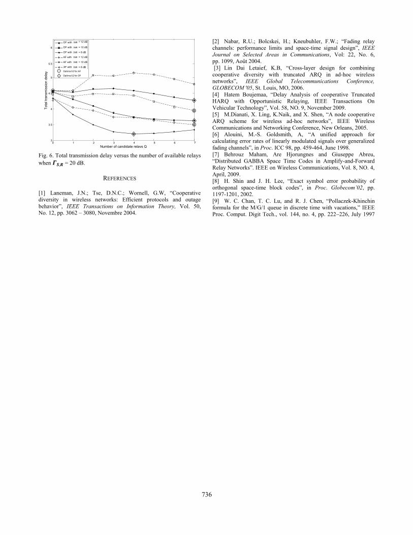
Fig. 6. Total transmission delay versus the number of available relays
when = 20 dB.
REFERENCES
[1] Laneman, J.N.; Tse, D.N.C.; Wornell, G.W, “Cooperative
diversity in wireless networks: Efficient protocols and outage
behavior”, IEEE Transactions on Information Theory, Vol. 50, No. 12, pp. 3062 – 3080, Novembre 2004.
[2] Nabar, R.U.; Bolcskei, H.; Kneubuhler, F.W.; “Fading relay
channels: performance limits and space-time signal design”, IEEE
Journal on Selected Areas in Communications, Vol: 22, No. 6,
pp. 1099, Août 2004.
[3] Lin Dai Letaief, K.B, “Cross-layer design for combining
cooperative diversity with truncated ARQ in ad-hoc wireless
networks”, IEEE Global Telecommunications Conference,
GLOBECOM '05, St. Louis, MO, 2006.
[4] Hatem Boujemaa, “Delay Analysis of cooperative Truncated
HARQ with Opportunistic Relaying, IEEE Transactions On
Vehicular Technology”, Vol. 58, NO. 9, November 2009.
[5] M.Dianati, X. Ling, K.Naik, and X. Shen, “A node cooperative
ARQ scheme for wireless ad-hoc networks”, IEEE Wireless
Communications and Networking Conference, New Orleans, 2005.
[6] Alouini, M.-S. Goldsmith, A, “A unified approach for
calculating error rates of linearly modulated signals over generalized
fading channels”, in Proc. ICC 98, pp. 459-464, June 1998.
[7] Behrouz Maham, Are Hjorungnes and Giuseppe Abreu,
“Distributed GABBA Space Time Codes in Amplify-and-Forward
Relay Networks”. IEEE on Wireless Communications, Vol. 8, NO. 4,
April, 2009.
[8] H. Shin and J. H. Lee, “Exact symbol error probability of
orthogonal space-time block codes”, in Proc. Globecom’02, pp.
1197-1201, 2002.
[9] W. C. Chan, T. C. Lu, and R. J. Chen, “Pollaczek-Khinchin
formula for the M/G/1 queue in discrete time with vacations,” IEEE
Proc. Comput. Digit Tech., vol. 144, no. 4, pp. 222–226, July 1997
To
tal tr
an
sm
issio
n d
ela
y
6
5.5
5
4.5
4
3.5
3 0 1 2 3 4 5 6 7
Number of candidate relays Q
Tota
l tr
ansm
issio
n d
ela
y
6
SNR
= 12 dB
SR
SNR = 10 dB SR
SNR = 8 dB 5.5 SR
5
4.5
4
3.5
3
0 1 2 3 4 5 6 7 Number of candidate relays Q
0.7
DF with ΓR-D = 12 dB
DF with ΓR-D = 10 dB
0.6 DF with ΓR-D = 8 dB
AF with ΓR-D = 12 dB
AF with ΓR-D = 10 dB
0.5 AF with ΓR-D = 8 dB
0.4
0.3
0.2
0.1
0
0 1 2 3 4 5 6 7 Number of candidate relays Q
0.7
DF with ΓR-D = 12 dB
DF with ΓR-D = 10 dB
0.6 DF with ΓR-D = 8 dB
AF with ΓR-D = 12 dB
AF with ΓR-D = 10 dB
0.5 AF with ΓR-D = 8 dB
0.4
0.3
0.2
0.1
0
0 1 2 3 4 5 6 7 Number of candidate relays Q
SNR
SNR
SNR
0.7
DF with ΓR-D = 12 dB
DF with ΓR-D = 10 dB
0.6 DF with ΓR-D = 8 dB
AF with ΓR-D = 12 dB
AF with ΓR-D = 10 dB
0.5 AF with ΓR-D = 8 dB
0.4
0.3
0.2
0.1
0
0 1 2 3 4 5 6 7 Number of candidate relays Q
SNR
SNR
SNR
0.7
DF with ΓR-D = 12 dB
DF with ΓR-D = 10 dB
0.6 DF with ΓR-D = 8 dB
AF with ΓR-D = 12 dB
AF with ΓR-D = 10 dB
0.5 AF with ΓR-D = 8 dB
0.4
0.3
0.2
0.1
0
0 1 2 3 4 5 6 7 Number of candidate relays Q
0.7
DF with ΓR-D = 12 dB
DF with ΓR-D = 10 dB
0.6 DF with ΓR-D = 8 dB
AF with ΓR-D = 12 dB
AF with ΓR-D = 10 dB
0.5 AF with ΓR-D = 8 dB
0.4
0.3
0.2
0.1
0
0 1 2 3 4 5 6 7 Number of candidate relays Q
SNR
SNR
SNR
0.7
DF with ΓR-D = 12 dB
DF with ΓR-D = 10 dB
0.6 DF with ΓR-D = 8 dB
AF with ΓR-D = 12 dB
AF with ΓR-D = 10 dB
0.5 AF with ΓR-D = 8 dB
0.4
0.3
0.2
0.1
0
0 1 2 3 4 5 6 7 Number of candidate relays Q
SNR
SNR
SNR
0.7
DF with ΓR-D = 12 dB
DF with ΓR-D = 10 dB
0.6 DF with ΓR-D = 8 dB
AF with ΓR-D = 12 dB
AF with ΓR-D = 10 dB
0.5 AF with ΓR-D = 8 dB
0.4
0.3
0.2
0.1
0
0 1 2 3 4 5 6 7 Number of candidate relays Q
0.7
DF with ΓR-D = 12 dB
DF with ΓR-D = 10 dB
0.6 DF with ΓR-D = 8 dB
AF with ΓR-D = 12 dB
AF with ΓR-D = 10 dB
0.5 AF with ΓR-D = 8 dB
0.4
0.3
0.2
0.1
0
0 1 2 3 4 5 6 7 Number of candidate relays Q
SNR
SNR
SNR
0.7
DF with ΓR-D = 12 dB
DF with ΓR-D = 10 dB
0.6 DF with ΓR-D = 8 dB
AF with ΓR-D = 12 dB
AF with ΓR-D = 10 dB
0.5 AF with ΓR-D = 8 dB
0.4
0.3
0.2
0.1
0
0 1 2 3 4 5 6 7 Number of candidate relays Q
SNR
SNR
SNR
0.7
DF with ΓR-D = 12 dB
DF with ΓR-D = 10 dB
0.6 DF with ΓR-D = 8 dB
AF with ΓR-D = 12 dB
AF with ΓR-D = 10 dB
0.5 AF with ΓR-D = 8 dB
0.4
0.3
0.2
0.1
0
0 1 2 3 4 5 6 7 Number of candidate relays Q
0.7
DF with ΓR-D = 12 dB
DF with ΓR-D = 10 dB
0.6 DF with ΓR-D = 8 dB
AF with ΓR-D = 12 dB
AF with ΓR-D = 10 dB
0.5 AF with ΓR-D = 8 dB
0.4
0.3
0.2
0.1
0
0 1 2 3 4 5 6 7 Number of candidate relays Q
SNR
SNR
SNR
0.7
DF with ΓR-D = 12 dB
DF with ΓR-D = 10 dB
0.6 DF with ΓR-D = 8 dB
AF with ΓR-D = 12 dB
AF with ΓR-D = 10 dB
0.5 AF with ΓR-D = 8 dB
0.4
0.3
0.2
0.1
0
0 1 2 3 4 5 6 7 Number of candidate relays Q
SNR
SNR
SNR
0.7
DF with ΓR-D = 12 dB
DF with ΓR-D = 10 dB
0.6 DF with ΓR-D = 8 dB
AF with ΓR-D = 12 dB
AF with ΓR-D = 10 dB
0.5 AF with ΓR-D = 8 dB
0.4
0.3
0.2
0.1
0
0 1 2 3 4 5 6 7 Number of candidate relays Q
0.7
DF with ΓR-D = 12 dB
DF with ΓR-D = 10 dB
0.6 DF with ΓR-D = 8 dB
AF with ΓR-D = 12 dB
AF with ΓR-D = 10 dB
0.5 AF with ΓR-D = 8 dB
0.4
0.3
0.2
0.1
0
0 1 2 3 4 5 6 7 Number of candidate relays Q
SNR
SNR
SNR
0.7
DF with ΓR-D = 12 dB
DF with ΓR-D = 10 dB
0.6 DF with ΓR-D = 8 dB
AF with ΓR-D = 12 dB
AF with ΓR-D = 10 dB
0.5 AF with ΓR-D = 8 dB
0.4
0.3
0.2
0.1
0
0 1 2 3 4 5 6 7 Number of candidate relays Q
SNR
SNR
SNR
0.7
DF with ΓR-D = 12 dB
DF with ΓR-D = 10 dB
0.6 DF with ΓR-D = 8 dB
AF with ΓR-D = 12 dB
AF with ΓR-D = 10 dB
0.5 AF with ΓR-D = 8 dB
0.4
0.3
0.2
0.1
0
0 1 2 3 4 5 6 7 Number of candidate relays Q
0.7
DF with ΓR-D = 12 dB
DF with ΓR-D = 10 dB
0.6 DF with ΓR-D = 8 dB
AF with ΓR-D = 12 dB
AF with ΓR-D = 10 dB
0.5 AF with ΓR-D = 8 dB
0.4
0.3
0.2
0.1
0
0 1 2 3 4 5 6 7 Number of candidate relays Q
SNR
SNR
SNR
0.7
DF with ΓR-D = 12 dB
DF with ΓR-D = 10 dB
0.6 DF with ΓR-D = 8 dB
AF with ΓR-D = 12 dB
AF with ΓR-D = 10 dB
0.5 AF with ΓR-D = 8 dB
0.4
0.3
0.2
0.1
0
0 1 2 3 4 5 6 7 Number of candidate relays Q
SNR
SNR
SNR
0.7
DF with ΓR-D = 12 dB
DF with ΓR-D = 10 dB
0.6 DF with ΓR-D = 8 dB
AF with ΓR-D = 12 dB
AF with ΓR-D = 10 dB
0.5 AF with ΓR-D = 8 dB
0.4
0.3
0.2
0.1
0
0 1 2 3 4 5 6 7 Number of candidate relays Q
Optimal Q for AF
Optimal Q for DF
To
tal tr
an
sm
issio
n d
ela
y
6
5.5
5
4.5
4
3.5
3 0 1 2 3 4 5 6 7
Number of candidate relays Q
To
tal tr
ansm
issio
n d
ela
y
6
SNR
= 12 dB
SR
SNR = 10 dB SR
SNR = 8 dB 5.5 SR
5
4.5
4
3.5
3
0 1 2 3 4 5 6 7 Number of candidate relays Q
0.7
DF with ΓR-D = 12 dB
DF with ΓR-D = 10 dB
0.6 DF with ΓR-D = 8 dB
AF with ΓR-D = 12 dB
AF with ΓR-D = 10 dB
0.5 AF with ΓR-D = 8 dB
0.4
0.3
0.2
0.1
0
0 1 2 3 4 5 6 7 Number of candidate relays Q
0.7
DF with ΓR-D = 12 dB
DF with ΓR-D = 10 dB
0.6 DF with ΓR-D = 8 dB
AF with ΓR-D = 12 dB
AF with ΓR-D = 10 dB
0.5 AF with ΓR-D = 8 dB
0.4
0.3
0.2
0.1
0
0 1 2 3 4 5 6 7 Number of candidate relays Q
SNR
SNR
SNR
0.7
DF with ΓR-D = 12 dB
DF with ΓR-D = 10 dB
0.6 DF with ΓR-D = 8 dB
AF with ΓR-D = 12 dB
AF with ΓR-D = 10 dB
0.5 AF with ΓR-D = 8 dB
0.4
0.3
0.2
0.1
0
0 1 2 3 4 5 6 7 Number of candidate relays Q
SNR
SNR
SNR
0.7
DF with ΓR-D = 12 dB
DF with ΓR-D = 10 dB
0.6 DF with ΓR-D = 8 dB
AF with ΓR-D = 12 dB
AF with ΓR-D = 10 dB
0.5 AF with ΓR-D = 8 dB
0.4
0.3
0.2
0.1
0
0 1 2 3 4 5 6 7 Number of candidate relays Q
0.7
DF with ΓR-D = 12 dB
DF with ΓR-D = 10 dB
0.6 DF with ΓR-D = 8 dB
AF with ΓR-D = 12 dB
AF with ΓR-D = 10 dB
0.5 AF with ΓR-D = 8 dB
0.4
0.3
0.2
0.1
0
0 1 2 3 4 5 6 7 Number of candidate relays Q
SNR
SNR
SNR
0.7
DF with ΓR-D = 12 dB
DF with ΓR-D = 10 dB
0.6 DF with ΓR-D = 8 dB
AF with ΓR-D = 12 dB
AF with ΓR-D = 10 dB
0.5 AF with ΓR-D = 8 dB
0.4
0.3
0.2
0.1
0
0 1 2 3 4 5 6 7 Number of candidate relays Q
SNR
SNR
SNR
0.7
DF with ΓR-D = 12 dB
DF with ΓR-D = 10 dB
0.6 DF with ΓR-D = 8 dB
AF with ΓR-D = 12 dB
AF with ΓR-D = 10 dB
0.5 AF with ΓR-D = 8 dB
0.4
0.3
0.2
0.1
0
0 1 2 3 4 5 6 7 Number of candidate relays Q
0.7
DF with ΓR-D = 12 dB
DF with ΓR-D = 10 dB
0.6 DF with ΓR-D = 8 dB
AF with ΓR-D = 12 dB
AF with ΓR-D = 10 dB
0.5 AF with ΓR-D = 8 dB
0.4
0.3
0.2
0.1
0
0 1 2 3 4 5 6 7 Number of candidate relays Q
SNR
SNR
SNR
0.7
DF with ΓR-D = 12 dB
DF with ΓR-D = 10 dB
0.6 DF with ΓR-D = 8 dB
AF with ΓR-D = 12 dB
AF with ΓR-D = 10 dB
0.5 AF with ΓR-D = 8 dB
0.4
0.3
0.2
0.1
0
0 1 2 3 4 5 6 7 Number of candidate relays Q
SNR
SNR
SNR
0.7
DF with ΓR-D = 12 dB
DF with ΓR-D = 10 dB
0.6 DF with ΓR-D = 8 dB
AF with ΓR-D = 12 dB
AF with ΓR-D = 10 dB
0.5 AF with ΓR-D = 8 dB
0.4
0.3
0.2
0.1
0
0 1 2 3 4 5 6 7 Number of candidate relays Q
0.7
DF with ΓR-D = 12 dB
DF with ΓR-D = 10 dB
0.6 DF with ΓR-D = 8 dB
AF with ΓR-D = 12 dB
AF with ΓR-D = 10 dB
0.5 AF with ΓR-D = 8 dB
0.4
0.3
0.2
0.1
0
0 1 2 3 4 5 6 7 Number of candidate relays Q
SNR
SNR
SNR
0.7
DF with ΓR-D = 12 dB
DF with ΓR-D = 10 dB
0.6 DF with ΓR-D = 8 dB
AF with ΓR-D = 12 dB
AF with ΓR-D = 10 dB
0.5 AF with ΓR-D = 8 dB
0.4
0.3
0.2
0.1
0
0 1 2 3 4 5 6 7 Number of candidate relays Q
SNR
SNR
SNR
0.7
DF with ΓR-D = 12 dB
DF with ΓR-D = 10 dB
0.6 DF with ΓR-D = 8 dB
AF with ΓR-D = 12 dB
AF with ΓR-D = 10 dB
0.5 AF with ΓR-D = 8 dB
0.4
0.3
0.2
0.1
0
0 1 2 3 4 5 6 7 Number of candidate relays Q
0.7
DF with ΓR-D = 12 dB
DF with ΓR-D = 10 dB
0.6 DF with ΓR-D = 8 dB
AF with ΓR-D = 12 dB
AF with ΓR-D = 10 dB
0.5 AF with ΓR-D = 8 dB
0.4
0.3
0.2
0.1
0
0 1 2 3 4 5 6 7 Number of candidate relays Q
SNR
SNR
SNR
0.7
DF with ΓR-D = 12 dB
DF with ΓR-D = 10 dB
0.6 DF with ΓR-D = 8 dB
AF with ΓR-D = 12 dB
AF with ΓR-D = 10 dB
0.5 AF with ΓR-D = 8 dB
0.4
0.3
0.2
0.1
0
0 1 2 3 4 5 6 7 Number of candidate relays Q
SNR
SNR
SNR
0.7
DF with ΓR-D = 12 dB
DF with ΓR-D = 10 dB
0.6 DF with ΓR-D = 8 dB
AF with ΓR-D = 12 dB
AF with ΓR-D = 10 dB
0.5 AF with ΓR-D = 8 dB
0.4
0.3
0.2
0.1
0
0 1 2 3 4 5 6 7 Number of candidate relays Q
0.7
DF with ΓR-D = 12 dB
DF with ΓR-D = 10 dB
0.6 DF with ΓR-D = 8 dB
AF with ΓR-D = 12 dB
AF with ΓR-D = 10 dB
0.5 AF with ΓR-D = 8 dB
0.4
0.3
0.2
0.1
0
0 1 2 3 4 5 6 7 Number of candidate relays Q
SNR
SNR
SNR
0.7
DF with ΓR-D = 12 dB
DF with ΓR-D = 10 dB
0.6 DF with ΓR-D = 8 dB
AF with ΓR-D = 12 dB
AF with ΓR-D = 10 dB
0.5 AF with ΓR-D = 8 dB
0.4
0.3
0.2
0.1
0
0 1 2 3 4 5 6 7 Number of candidate relays Q
SNR
SNR
SNR
0.7
DF with ΓR-D = 12 dB
DF with ΓR-D = 10 dB
0.6 DF with ΓR-D = 8 dB
AF with ΓR-D = 12 dB
AF with ΓR-D = 10 dB
0.5 AF with ΓR-D = 8 dB
0.4
0.3
0.2
0.1
0
0 1 2 3 4 5 6 7 Number of candidate relays Q
Tota
l tr
ansm
issio
n d
ela
y
6
SNR
= 12 dB
SR
SNR = 10 dB SR
SNR = 8 dB 5.5 SR
5
4.5
4
3.5
3
0 1 2 3 4 5 6 7 Number of candidate relays Q
0.7
DF with ΓR-D = 12 dB
DF with ΓR-D = 10 dB
0.6 DF with ΓR-D = 8 dB
AF with ΓR-D = 12 dB
AF with ΓR-D = 10 dB
0.5 AF with ΓR-D = 8 dB
0.4
0.3
0.2
0.1
0
0 1 2 3 4 5 6 7 Number of candidate relays Q
0.7
DF with ΓR-D = 12 dB
DF with ΓR-D = 10 dB
0.6 DF with ΓR-D = 8 dB
AF with ΓR-D = 12 dB
AF with ΓR-D = 10 dB
0.5 AF with ΓR-D = 8 dB
0.4
0.3
0.2
0.1
0
0 1 2 3 4 5 6 7 Number of candidate relays Q
SNR
SNR
SNR
0.7
DF with ΓR-D = 12 dB
DF with ΓR-D = 10 dB
0.6 DF with ΓR-D = 8 dB
AF with ΓR-D = 12 dB
AF with ΓR-D = 10 dB
0.5 AF with ΓR-D = 8 dB
0.4
0.3
0.2
0.1
0
0 1 2 3 4 5 6 7 Number of candidate relays Q
SNR
SNR
SNR
0.7
DF with ΓR-D = 12 dB
DF with ΓR-D = 10 dB
0.6 DF with ΓR-D = 8 dB
AF with ΓR-D = 12 dB
AF with ΓR-D = 10 dB
0.5 AF with ΓR-D = 8 dB
0.4
0.3
0.2
0.1
0
0 1 2 3 4 5 6 7 Number of candidate relays Q
0.7
DF with ΓR-D = 12 dB
DF with ΓR-D = 10 dB
0.6 DF with ΓR-D = 8 dB
AF with ΓR-D = 12 dB
AF with ΓR-D = 10 dB
0.5 AF with ΓR-D = 8 dB
0.4
0.3
0.2
0.1
0
0 1 2 3 4 5 6 7 Number of candidate relays Q
SNR
SNR
SNR
0.7
DF with ΓR-D = 12 dB
DF with ΓR-D = 10 dB
0.6 DF with ΓR-D = 8 dB
AF with ΓR-D = 12 dB
AF with ΓR-D = 10 dB
0.5 AF with ΓR-D = 8 dB
0.4
0.3
0.2
0.1
0
0 1 2 3 4 5 6 7 Number of candidate relays Q
SNR
SNR
SNR
0.7
DF with ΓR-D = 12 dB
DF with ΓR-D = 10 dB
0.6 DF with ΓR-D = 8 dB
AF with ΓR-D = 12 dB
AF with ΓR-D = 10 dB
0.5 AF with ΓR-D = 8 dB
0.4
0.3
0.2
0.1
0
0 1 2 3 4 5 6 7 Number of candidate relays Q
0.7
DF with ΓR-D = 12 dB
DF with ΓR-D = 10 dB
0.6 DF with ΓR-D = 8 dB
AF with ΓR-D = 12 dB
AF with ΓR-D = 10 dB
0.5 AF with ΓR-D = 8 dB
0.4
0.3
0.2
0.1
0
0 1 2 3 4 5 6 7 Number of candidate relays Q
SNR
SNR
SNR
0.7
DF with ΓR-D = 12 dB
DF with ΓR-D = 10 dB
0.6 DF with ΓR-D = 8 dB
AF with ΓR-D = 12 dB
AF with ΓR-D = 10 dB
0.5 AF with ΓR-D = 8 dB
0.4
0.3
0.2
0.1
0
0 1 2 3 4 5 6 7 Number of candidate relays Q
SNR
SNR
SNR
0.7
DF with ΓR-D = 12 dB
DF with ΓR-D = 10 dB
0.6 DF with ΓR-D = 8 dB
AF with ΓR-D = 12 dB
AF with ΓR-D = 10 dB
0.5 AF with ΓR-D = 8 dB
0.4
0.3
0.2
0.1
0
0 1 2 3 4 5 6 7 Number of candidate relays Q
0.7
DF with ΓR-D = 12 dB
DF with ΓR-D = 10 dB
0.6 DF with ΓR-D = 8 dB
AF with ΓR-D = 12 dB
AF with ΓR-D = 10 dB
0.5 AF with ΓR-D = 8 dB
0.4
0.3
0.2
0.1
0
0 1 2 3 4 5 6 7 Number of candidate relays Q
SNR
SNR
SNR
0.7
DF with ΓR-D = 12 dB
DF with ΓR-D = 10 dB
0.6 DF with ΓR-D = 8 dB
AF with ΓR-D = 12 dB
AF with ΓR-D = 10 dB
0.5 AF with ΓR-D = 8 dB
0.4
0.3
0.2
0.1
0
0 1 2 3 4 5 6 7 Number of candidate relays Q
SNR
SNR
SNR
0.7
DF with ΓR-D = 12 dB
DF with ΓR-D = 10 dB
0.6 DF with ΓR-D = 8 dB
AF with ΓR-D = 12 dB
AF with ΓR-D = 10 dB
0.5 AF with ΓR-D = 8 dB
0.4
0.3
0.2
0.1
0
0 1 2 3 4 5 6 7 Number of candidate relays Q
0.7
DF with ΓR-D = 12 dB
DF with ΓR-D = 10 dB
0.6 DF with ΓR-D = 8 dB
AF with ΓR-D = 12 dB
AF with ΓR-D = 10 dB
0.5 AF with ΓR-D = 8 dB
0.4
0.3
0.2
0.1
0
0 1 2 3 4 5 6 7 Number of candidate relays Q
SNR
SNR
SNR
0.7
DF with ΓR-D = 12 dB
DF with ΓR-D = 10 dB
0.6 DF with ΓR-D = 8 dB
AF with ΓR-D = 12 dB
AF with ΓR-D = 10 dB
0.5 AF with ΓR-D = 8 dB
0.4
0.3
0.2
0.1
0
0 1 2 3 4 5 6 7 Number of candidate relays Q
SNR
SNR
SNR
0.7
DF with ΓR-D = 12 dB
DF with ΓR-D = 10 dB
0.6 DF with ΓR-D = 8 dB
AF with ΓR-D = 12 dB
AF with ΓR-D = 10 dB
0.5 AF with ΓR-D = 8 dB
0.4
0.3
0.2
0.1
0
0 1 2 3 4 5 6 7 Number of candidate relays Q
0.7
DF with ΓR-D = 12 dB
DF with ΓR-D = 10 dB
0.6 DF with ΓR-D = 8 dB
AF with ΓR-D = 12 dB
AF with ΓR-D = 10 dB
0.5 AF with ΓR-D = 8 dB
0.4
0.3
0.2
0.1
0
0 1 2 3 4 5 6 7 Number of candidate relays Q
SNR
SNR
SNR
0.7
DF with ΓR-D = 12 dB
DF with ΓR-D = 10 dB
0.6 DF with ΓR-D = 8 dB
AF with ΓR-D = 12 dB
AF with ΓR-D = 10 dB
0.5 AF with ΓR-D = 8 dB
0.4
0.3
0.2
0.1
0
0 1 2 3 4 5 6 7 Number of candidate relays Q
SNR
SNR
SNR
0.7
DF with ΓR-D = 12 dB
DF with ΓR-D = 10 dB
0.6 DF with ΓR-D = 8 dB
AF with ΓR-D = 12 dB
AF with ΓR-D = 10 dB
0.5 AF with ΓR-D = 8 dB
0.4
0.3
0.2
0.1
0
0 1 2 3 4 5 6 7 Number of candidate relays Q
Optimal Q for AF
Optimal Q for DF
736