three-phase ups topology and efficiency · pdf filethree-phase ups topology and efficiency...
TRANSCRIPT

1
Three-phase UPS Topology and Efficiency Enhancement
Liao Jen-ch'uan Kuo ch'ao-lung
Delta Electronics, Inc.
Abstract
The development of Taiwan's electronic science & technology and
semiconductor industry witnesses increasingly higher requirements on the quality of
power supply to precision instruments and equipment necessary for manufacturing
processes, thus driving the demand for large capacity three-phase UPS systems. In
the context of energy crisis and greenhouse effect, how to raise UPS operating
efficiency and reduce energy consumption and operation costs has become an
important issue faced by UPS vendors. Therefore, this paper, starting from
introducing topologies of three-phase UPS systems, describes the method for
improvement of UPS efficiency based on comparison of PFC and inverter topologies,
optimization of control methods, selection of key components & assemblies, and
operation of highly efficient ECO mode. Meanwhile, it also makes a brief introduction
about the current international regulations on UPS efficiency.
I. Introduction
Uninterrupted Power Supply (UPS) systems are mainly used to provide a
stable power supply for critical loads so as to prevent any loss of important
data due to poor power supply. Factors affecting electric power quality include
over-high or over-low voltage, voltage surge and noise, voltage flicker,
three-phase unbalance, harmonic distortion, frequency abnormity and mains
supply outage. Against the backdrop of energy crisis and greenhouse effect, it
is expected that UPS may also improve its conversion efficiency without
affecting its reliability, in addition to providing a stable output power supply,
which is its main function. Apart from environmental protection, such efficiency
improvement will also reduce power costs and operation costs. Take a 200kW
UPS as example, supposed its efficiency is raised from 92% to 96%, when
running at full load, it can save annually about 80,000 kWh electricity.

2
Meanwhile, reduction of heat due to the UPS efficiency improvement may
bring down the costs of installing air conditioners in datacenters as well as their
power consumption. As a result, how to improve UPS efficiency has become a
very important subject.
In this paper, Section Two discusses the basic topologies of three-phase
UPS systems and makes a brief introduction to UPS composition and
operation modes; Section Three is an overview of current international UPS
efficiency-related regulations; Section Four describes PFC topologies in UPS
double conversion, analyzes their characteristics and compares their
advantages and disadvantages; Section Five introduces inverter circuit
topologies commonly used in UPSs and their characteristics, and compares
their advantages and disadvantages; Section Six discusses the relation
between UPS control methods and efficiency; Section Seven explores and
compares power switch and magnetic component, key components in UPS;
Section Eight introduces high efficiency ECO mode operation; and Section
Nine draws conclusions.
II. Basic Topologies of UPS Systems
By topology, UPS systems can be classified into online UPS,
line-interactive UPS and offline UPS. When an offline UPS is used, the load
receives power directly from mains supply in normal case and by UPS battery
via inverter in case of mains outage. A line-interactive UPS is mainly different
from an offline UPS in that, if the input voltage of mains supply is instable, it will
provide a stable output to the load via voltage regulation and if there is mains
outage or frequency abnormity, it will supply power via its battery. An online
UPS with double conversion prevents the UPS output from being affected by
input voltage quality and steadily provides the load with pure power supply. If
the mains supply is interrupted, an online UPS will also supply power to the
load via its battery. By efficiency, the three types of UPS systems are in the
sequence of offline UPS > line-interactive UPS > online UPS; by power quality
supplied to the load, the sequence is online UPS > line-interactive UPS >
offline UPS.

3
The three-phase UPS systems currently available on market are mainly of
online type, and therefore, the basic topologies of three-phase online UPS
systems will be briefly introduced as follows. The basic topology of a
three-phase UPS mainly comprises a bypass static switch (Bypass STS), a
power factor correction circuit (PFC), an inverter (INV), an inverter static switch
(INV STS) and a charger, as shown in Fig. 1. In normal cases, a UPS mainly
outputs power by following the route of mains supply PFC circuit inverter
load to guarantee the quality of power supply and at the same time, to
charge the battery. In case of mains supply outage, the UPS will supply power
via its battery, and the inverter will convert DC voltage to pure AC sine-wave
voltage and supply the load. If the mains supply is recovered, the UPS will be
supplied again by the mains supply. If any abnormity found in the inverter, the
UPS will be supplied by the bypass power supply. Therefore, a UPS is a
stable, uninterrupted power supply to client’s critical loads that may help
prevent the client from huge loss caused by mains supply outage. UPS mainly
functions as a bridge for electricity conversion between the mains supply and
the load, and during the conversion from AC to DC and again back to AC
power supply, the power loss and conversion electricity loss will naturally
occur. In connection with this, many countries have released relevant
regulations to standardize the UPS conversion efficiency. The next section will
introduce international regulations related to UPS efficiency.
ACDC
DCAC
DCDC
Battery
LoadAC
Bypass STS
AC
INV STS
INVPFC
Charger
Fig. 1 Basic Topology of Three-phase Online UPS
4
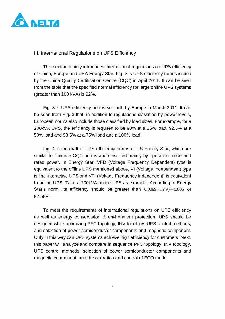
III. International Regulations on UPS Efficiency
This section mainly introduces international regulations on UPS efficiency
of China, Europe and USA Energy Star. Fig. 2 is UPS efficiency norms issued
by the China Quality Certification Centre (CQC) in April 2011. It can be seen
from the table that the specified normal efficiency for large online UPS systems
(greater than 100 kVA) is 92%.
Fig. 3 is UPS efficiency norms set forth by Europe in March 2011. It can
be seen from Fig. 3 that, in addition to regulations classified by power levels,
European norms also include those classified by load sizes. For example, for a
200kVA UPS, the efficiency is required to be 90% at a 25% load, 92.5% at a
50% load and 93.5% at a 75% load and a 100% load.
Fig. 4 is the draft of UPS efficiency norms of US Energy Star, which are
similar to Chinese CQC norms and classified mainly by operation mode and
rated power. In Energy Star, VFD (Voltage Frequency Dependent) type is
equivalent to the offline UPS mentioned above, VI (Voltage Independent) type
is line-interactive UPS and VFI (Voltage Frequency Independent) is equivalent
to online UPS. Take a 200kVA online UPS as example. According to Energy
Star’s norm, its efficiency should be greater than 805.0)Pln(0099.0 or
92.58%.
To meet the requirements of international regulations on UPS efficiency
as well as energy conservation & environment protection, UPS should be
designed while optimizing PFC topology, INV topology, UPS control methods,
and selection of power semiconductor components and magnetic component.
Only in this way can UPS systems achieve high efficiency for customers. Next,
this paper will analyze and compare in sequence PFC topology, INV topology,
UPS control methods, selection of power semiconductor components and
magnetic component, and the operation and control of ECO mode.

5
Fig. 1 CQC’s UPS Efficiency Norms
Fig. 3 European UPS Efficiency Norms

6
Fig. 4 Energy Star’s UPS Efficiency Norms
IV. Topology of PFC
The PFC circuit is mainly used to provide a stable DC power supply,
reduce harmonic waves at mains supply input end and lower losses of reactive
power. There are various types of PFC topologies in UPS systems. Each of
them has their respective strengths and weaknesses in terms of their impacts
on efficiency, and therefore, is suitable for different applications, which are to
be detailed as follows.
1. Three-phase Two-switch Three-level Boost Converter
A Three-phase two-switch three-level boost converter is as shown in Fig.
5, wherein the three-phase power input is rectified into a stable DC power
supply by a three-phase SCR first and then, inductor, IGBT and diode in
sequence. As only two IGBTs are used in such topology, it boasts of low
costs. However, it is unable to enlarge power levels due to the usage of
only two IGBTs. The disadvantage of such topology lies in high harmonic
wave distortion of its input current. The advantage of two-switch
three-level topology is that its switch assembly is subject to bus voltage
only and therefore, low withstand voltage switches can be used, thus
enhancing its conversion efficiency.
Fig. 5 Three-phase Two-switch Three-level Boost Converter
2. Three-phase Six-switch Boost Converter
A three-phase six-switch boost converter is of a common three-phase PFC
topology consisting of six active switches and three inductors, as shown in
R
S
T
N
+Bus
-Bus

7
Fig. 6. They are suitable for high power level applications. The main
disadvantage of a three-phase six-switch boost converter is that its
switches must withstand a voltage more than twice of bus voltage, leading
to a great increase of switching loss. As a result, three-phase six-switch
boost converters generally have a relatively low switching frequency so as
to reduce its switching loss.
Fig. 6 Three-phase Six-switch Boost Converter
3. Three-level Boost Converter
The application of a three-level boost converter is as shown in Fig. 7. It
comprises six switches, six fast diodes, six slow diodes and three
inductors. The switch assembly of three-level boost converter is subject to
bus voltage only and therefore, low withstand voltage switches can be
used to effectively reduce the switching loss, thus enhancing its
conversion efficiency.
+Bus
-Bus
R
T
S
8
R
N
+Bus
S
-Bus
T
Fig. 7 Three-level Boost Converter
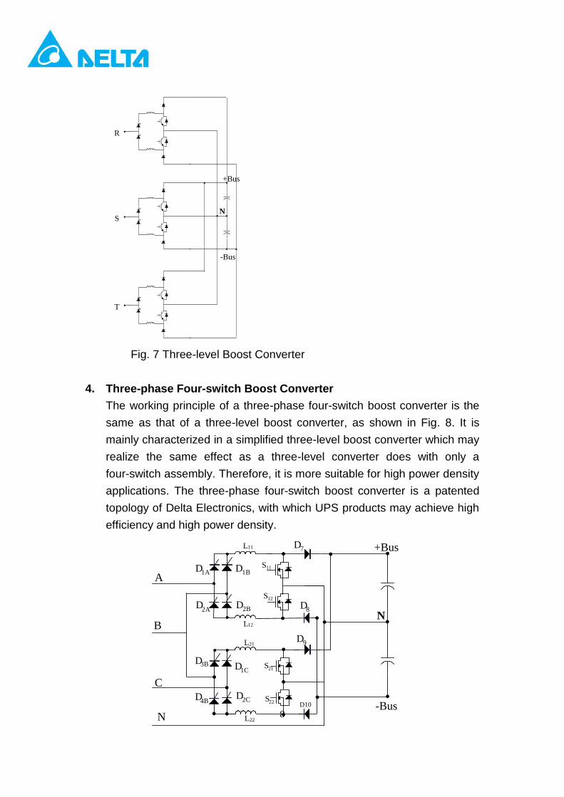
4. Three-phase Four-switch Boost Converter
The working principle of a three-phase four-switch boost converter is the
same as that of a three-level boost converter, as shown in Fig. 8. It is
mainly characterized in a simplified three-level boost converter which may
realize the same effect as a three-level converter does with only a
four-switch assembly. Therefore, it is more suitable for high power density
applications. The three-phase four-switch boost converter is a patented
topology of Delta Electronics, with which UPS products may achieve high
efficiency and high power density.
S12
S11
L11
L12
S22
S21
L21
L22
D1A
D2A
D1C
D1B
D2B
D2C
D3B
D4B
A
B
C
N
D9
D8
D7
D10
N
+Bus
-Bus

9
Fig. 8 Three-phase Four-switch Boost Converter
Table 1 compares the above-mentioned four PFC circuits in terms of current
harmonic wave distortion, efficiency, magnetic component quantity,
semiconductor assembly cost and availability of dual-direction current flow
capacity.
It can be known from the table that these four topologies have pros and cons,
and designers should select a suitable one in light of applications and product
positioning.
Table 1 Comparison of PFC Circuit Topologies
Topology
Current
harmonic
wave
distortion
Efficiency
Magnetic
component
quantity
Semiconductor
component
costs
Dual-direction
current flow
Three-phase
Two-switch
Three-level
Boost
Converter
Poor High 2 Low No
Three-phase
Six-switch
Boost
converter
Good High 3 Medium Yes
Three-level
Boost
Converter
Good Relatively
high 6 High No
Three-phase
Four-switch
Boost
Converter
Good Relatively
high 4 Medium No
V. Topology of Inverters

10
1. Three-phase Isolated Full-Bridge Inverter
A three-phase isolated full-bridge inverter is as shown in Fig. 9. It has a
relatively low bus voltage and mainly generates a boost and an N wire via an
output isolated transformer to supply the load. As its output isolated
transformer has both large size and weight and also a very high power loss,
the efficiency of a three-phase isolated full-bridge inverter is relatively low.
Fig. 9 Three-phase Isolated Full-Bridge Inverter
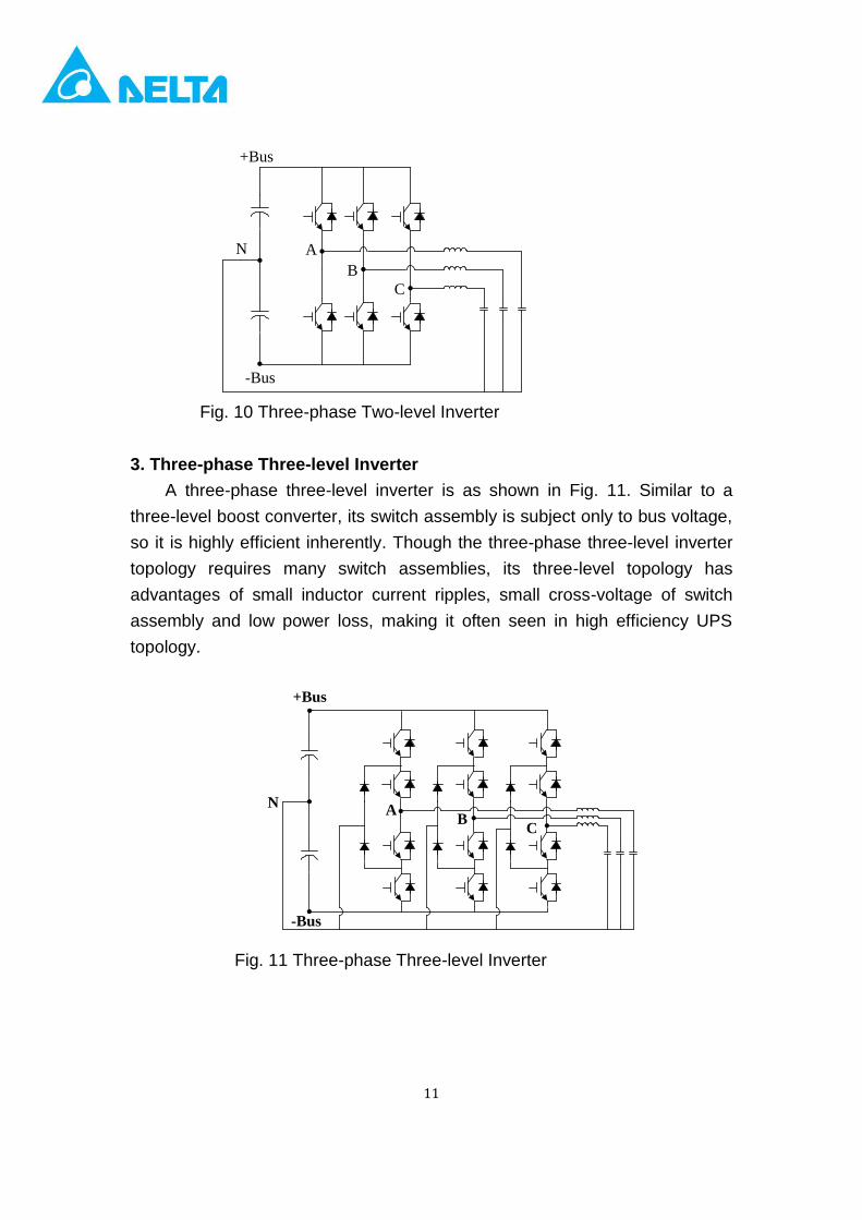
2. Three-phase Two-level Inverter
A three-phase two-level inverter is as shown in Fig. 10. Its main
disadvantage is that the switch assembly must have a withstand voltage more
than twice of the bus voltage, restricting its switching frequency. Therefore,
how to select a switching frequency and change the control algorithm so as to
enhance the conversion efficiency of two-level topology has become a main
subject for designers.
+Bus
-Bus
+Bus
-Bus
+Bus
-Bus
R
S
T
N
Open-delta
transformer
11
Fig. 10 Three-phase Two-level Inverter
3. Three-phase Three-level Inverter
A three-phase three-level inverter is as shown in Fig. 11. Similar to a
three-level boost converter, its switch assembly is subject only to bus voltage,
so it is highly efficient inherently. Though the three-phase three-level inverter
topology requires many switch assemblies, its three-level topology has
advantages of small inductor current ripples, small cross-voltage of switch
assembly and low power loss, making it often seen in high efficiency UPS
topology.
Fig. 11 Three-phase Three-level Inverter
+Bus
-Bus
N A
B
C
N
+Bus
-Bus
AB
C

12
Table 2 compares the abovementioned three inverter topologies in terms of
harmonic wave distortion of output voltage, efficiency, magnetic component
quantity, semiconductor assembly costs and availability of dual-direction
current flow capacity. Currently, the main trend is to use a topology without
transformers.
Table 2 Comparison of Inverter Topologies
Topology
Voltage
harmonic
wave
distortion
Efficiency
Magnetic
component
quantity
Semiconductor
component
costs
Dual-direction
current flow
Three-phase
Two-level
Inverter
Good High 3 Low Yes
Three-phase
Three-level
Inverter
Good Highest 3 High Yes
Three-phase
Isolated
Full-bridge
Inverter
Good Poor 3 (large) High Yes
VI. UPS Control Methods
For control methods of a UPS inverter, SPWM (sinusoidal pulse width
modulation) is generally adopted for pulse width modulation, as shown in Fig.
12. The control signal (Vctrl) is compared with triangle waves to generate a
PWM signal for driving the switch assembly. The SPWM in inverter application
has a bus voltage utilization rate of 0.866, i.e., the bus voltage in a 380Vac
system should be at least greater than 620V. As this control method has a low
utilization rate of bus voltage, a high bus voltage is needed, thus increasing the
switching loss of switch component. Meanwhile, with a high bus voltage, the

13
voltage stress of switch component will increase accordingly, and some
Snubber circuits have to be added for absorbing voltage surge, leading to
more power loss. Therefore, if the utilization rate of bus voltage can be
improved by changing control methods, the system efficiency will be increased
accordingly.
Fig. 12 Three-phase SPWM Control Method
As shown in Fig. 13, a third harmonic wave Vz is injected into the original
control signal (Vctrl) and the new control signal generated is then compared
with the triangular wave to generate a PWM signal for driving the switch
component. The harmonic injection method can effectively increase the
utilization rate of bus voltage from 0.866 to 1. In other words, with the harmonic
injection method, a system originally requiring a 620V bus voltage will now
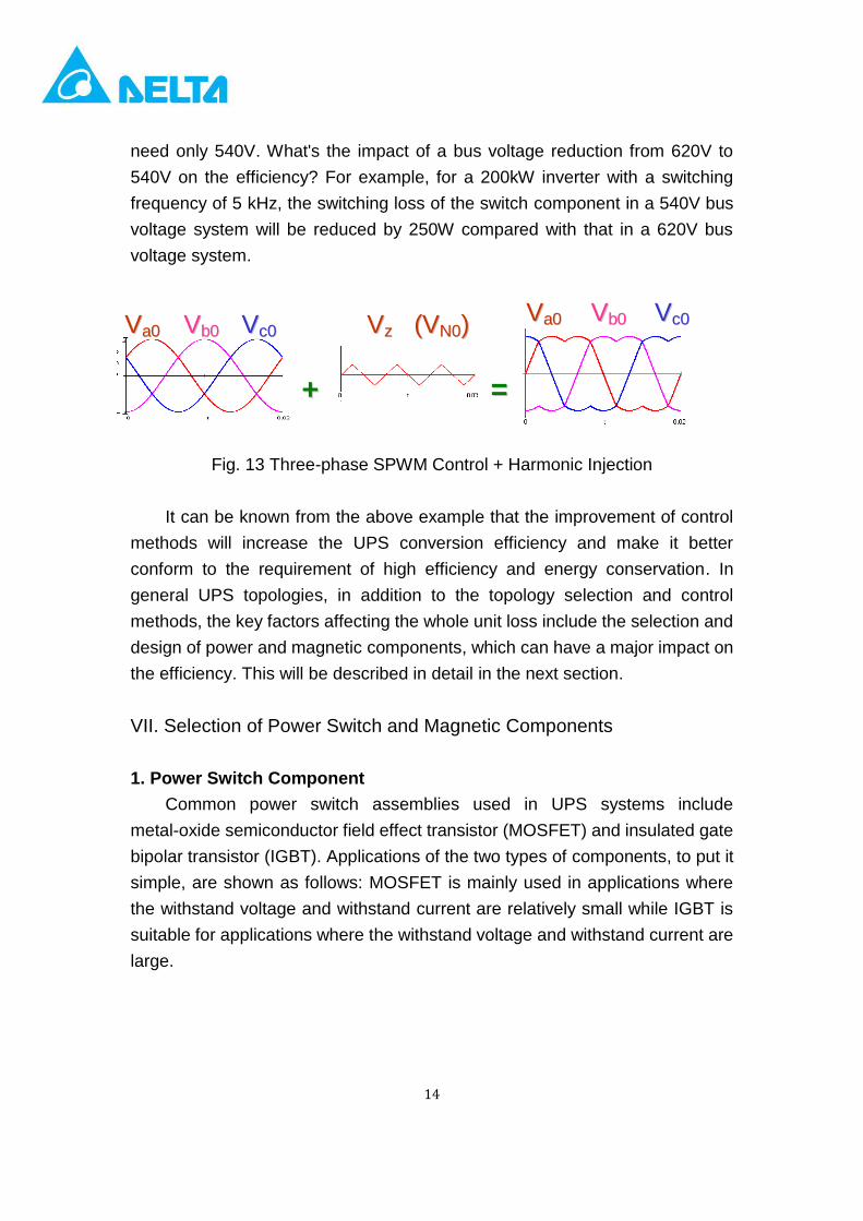
14
need only 540V. What's the impact of a bus voltage reduction from 620V to
540V on the efficiency? For example, for a 200kW inverter with a switching
frequency of 5 kHz, the switching loss of the switch component in a 540V bus
voltage system will be reduced by 250W compared with that in a 620V bus
voltage system.
Fig. 13 Three-phase SPWM Control + Harmonic Injection
It can be known from the above example that the improvement of control
methods will increase the UPS conversion efficiency and make it better
conform to the requirement of high efficiency and energy conservation. In
general UPS topologies, in addition to the topology selection and control
methods, the key factors affecting the whole unit loss include the selection and
design of power and magnetic components, which can have a major impact on
the efficiency. This will be described in detail in the next section.
VII. Selection of Power Switch and Magnetic Components
1. Power Switch Component
Common power switch assemblies used in UPS systems include
metal-oxide semiconductor field effect transistor (MOSFET) and insulated gate
bipolar transistor (IGBT). Applications of the two types of components, to put it
simple, are shown as follows: MOSFET is mainly used in applications where
the withstand voltage and withstand current are relatively small while IGBT is
suitable for applications where the withstand voltage and withstand current are
large.
VVzz ((VVNN00)) VVaa00 VVbb00 VVcc00 VVaa00 VVbb00 VVcc00
++ ==
15
The current mainstream MOSFET used in UPS is CoolMOS, as CoolMOS
has a low Rds,on and low conduction loss, enabling it to withstand a high
current. Therefore, it is often used in small power UPS systems (lower than
20kVA). Though IGBT is inferior to MOSFET in both switching speed and
switching loss, it has a higher power processing capacity. Therefore, IGBT
plays a very important role in high power applications.
Let’s take a 200kW UPS as example and make a comparison pertinent to
IGBT loss. For comparison, the PFC adopts a three-phase six-switch boost
transformer topology while the INV adopts a three-phase two-level inverter
topology. On this basis, we will compare the IGBT losses at different switching
frequencies and different bus voltages, and the losses of IGBT modules from
different vendors.
Fig. 14 compares IGBT losses at different switching frequencies. It can be
seen from the figure that the higher the switching frequency is, the higher the
IGBT loss will be. The IGBT loss at a 2 kHz switching frequency is roughly one
fifth that at a 20kHz switching frequency. Though the IGBT loss at a lower
switching frequency is smaller, the corresponding cost is a larger magnetic
component, leading to larger losses of magnetic component and a slower
response speed and poor bandwidth. Selection of switching frequency has a
direct impact on the UPS efficiency, but other conditions should also be
cross-compared so as to find out a good switching frequency point favorable to
the unit efficiency.

16
0
5000
10000
15000
20000
25000
2KHZ 4KHZ 6KHZ 8KHZ 10KHZ 12KHZ 16KHZ 20KHZ
Fig. 14 Analysis of IGBT Losses at Various Switching Frequencies
(200kW UPS; input /output voltage: 380/220V; bus voltage: 800V)
Fig. 15 makes an analysis on IGBT losses at various bus voltages. It can
be seen from the figure that the higher the bus voltage is, the larger the IGBT
loss will be. The bus voltage mainly affects the switching loss of IGBT, but it
has little influence on conduction loss. It can be known from the figure that how
to realize a low bus voltage in UPS systems is also an important indicator for
the UPSs' efficiency.
5000
5200
5400
5600
5800
6000
6200
6400
6600
6800
7000
640V 680V 720V 760V 800V 840V
Fig. 15 Analysis of IGBT Losses at Various Bus Voltages
(200kW UPS; input/output voltage: 380/220V; switching frequency: 5 kHz)

17
Table 3 compares losses of different IGBT modules under the same testing
conditions. It can be seen from the table that different IGBT modules, even
with the same package and same size, may have different power losses, and
such difference may be as large as 20%. Therefore, to improve UPS efficiency,
special attention should also be paid to the characteristics difference and
correct selection of IGBTs from different vendors.
Table 3 Loss Analysis of IGBTs from Various Vendors
(200kW UPS; input/output voltage: 380/220V; switching frequency: 5 kHz)
A B C D E
PFC Conduction loss 1165 1290 1066 1020 1141
PFC Switching loss 2208 2542 2391 2479 1948
INV Conduction loss 1087 1105 1017 1022 1165
INV Switching loss 2133 2428 2294 2383 1857
Total loss 6593 7365 6768 6904 6111
2. Magnetic Component
The loss of magnetic component also accounts for a considerable
proportion in the UPS unit loss. When selecting magnetic component,
switching frequency and topology are two main determinants. Designing of
magnetic component mainly depends on the ripple current in switching, which
is subject to topology and switching frequency. For example, the inductance
value required by a three-phase two-level inverter will be larger than that for a
three-phase three-level inverter. The main reason is that the cross-voltage of
the inductor of a three-phase two-level inverter is larger. The switching

18
frequency will also directly affect the ripple current of an inductor. Generally,
the higher the switching frequency is, the smaller the required induction value
of magnetic assembly will be, and also, the smaller the loss of magnetic
assembly will be.
In addition to switching frequency and topology, another key factor
affecting the loss of magnetic component is the materials it is made of. The
common materials for magnetic component include silicon steel sheet,
amorphous alloy, iron powder core, etc. Iron cores made of different materials
have their respective applications. Therefore, selecting a proper kind of
magnetic material also plays an important role in terms of UPS efficiency.
Silicon steel sheets are generally used in applications with a low switching
frequency. A high switching frequency will increase the iron loss of silicon steel
sheet sharply, thus greatly reducing the UPS efficiency. Amorphous alloys and
iron powder cores are widely used in UPS systems mainly because of their low
iron loss. There are various types of iron powder cores, such as MPP, High
Flux, Mage Flux and Sendust, and therefore, selecting an iron powder core
right for your application is also critical for ensuring the UPS efficiency.
VIII. High Efficiency ECO Mode Operation
The ECO mode operates in the following manner: when the mains supply
is normal, the load will receive power directly from the mains supply and the
inverter is generally at a no-load status; and in case of a mains outage, the
load will receive power from the inverter, as shown in Figs. 16 and 17. The
main advantage of the ECO mode is high energy conservation. The UPS
efficiency upon double conversion is generally about 92%~94%, and when
operating in the ECO mode, its efficiency will be improved to above 98%. The
main disadvantage of the ECO mode is that, in a mains supply outage, it needs
a switching time for the bypass mode to transfer into the inverter mode.
Especially, if the load is an inductive one such as a transformer, the phase

19
unlocking of mains supply and inverter voltage in such transfer may cause the
risks of transfer failure and power interruption. The patented ECO mode
transfer control method of Delta Electronics utilizes a rapid phase locking
control and detection mechanism to greatly reduce the transfer time and
eliminate the risk of transfer failure caused by unlocking, as shown in Fig. 18.
Fig. 16 ECO Mode in Normal Mains Supply
Fig. 17 ECO Mode in Abnormal Mains Supply

20
Fig. 18 ECO Mode Transfer Waveforms
IX. Conclusions
This paper mainly introduces three-phase UPS topologies and discusses
how to improve the UPS conversion efficiency by optimizing circuit topology,
control methods and combination of key components & assemblies. Delta
Electronics’ three-phase large power UPS system has successfully realized
the objective of high efficiency and met the requirement of high performance
by the abovementioned optimization of circuit topologies, control methods and
power components and assemblies. Fig. 19 is the efficiency curves of a
200kVA UPS practically measured by a certification institute. Its top efficiency
can reach 96.43% at a double conversion (on-line mode) power supply and
99.17% at an ECO mode power supply.
Test Condition:
BYPASS MODE→INV. MODE
CH1:R Phase Bypass Voltage (100V/DIV)
CH2:R Phase O/P Voltage (100V/DIV)
CH3:R Phase O/P Voltage ZOOM (100V/DIV)
CH4:R Phase INV. Current (100A/DIV)
Transfer time: 1. 728ms

21
Fig. 19 Efficiency Curves of Delta Electronics UPS
X. References
1. Relationship between Space-Vector Modulation and Three-Phase
Carrier-Based PWM: A Comprehensive Analysis, IEEE Transactions On
Industrial Electronics, VOL. 49, NO. 1, February 2002
2. High Performance Power Converter Systems for Nonlinear and
Unbalanced Load/Source, Thesis , Virginia Tech, 1999
3. Analysis and Comparison of Space Vector Modulation Schemes for
Three-leg and Four-leg Voltage Source Inverters, Virginia tech. thesis,
1997