three-phase power transmission lines phase power... · three-phase power transmission lines ... low...
TRANSCRIPT
1
Syed A. Rizvi Summer’12 ENS 441/ELT 437
Three-phase Power transmission Lines
The generators at the power plant produce voltages in the range of 11—33 KV. This voltage is
not suitable for bulk power transmission over long distances. Recall that electrical power is a
product of voltage and current. That is,
𝑆 = 𝑉 × 𝐼 (1)
It is clear from the equation (1) that for a given amount of power (S) to be transmitted, an
increase in the transmission line voltage (V) results is a proportional decrease in the current (I)
carried by that line. Reduced current in the transmission line, in turn, results in reduced diameter
needed for the conductors needed for the transmission line as well as lower losses along the line.
Furthermore, it will be shown later that the maximum amount of power that can be transmitted
over the power lines is directly proportional to the square of the transmission line voltage. That
means that if the voltage is doubled, the power handling capacity of the same line is increased by
a factor of four and if the voltage is increased by four times the power handling capacity of the
line is increased by a factor of 16 and so on. The voltage generated by the power plant is,
therefore, raised by using step-up power transformer before it is transmitted to load centers.
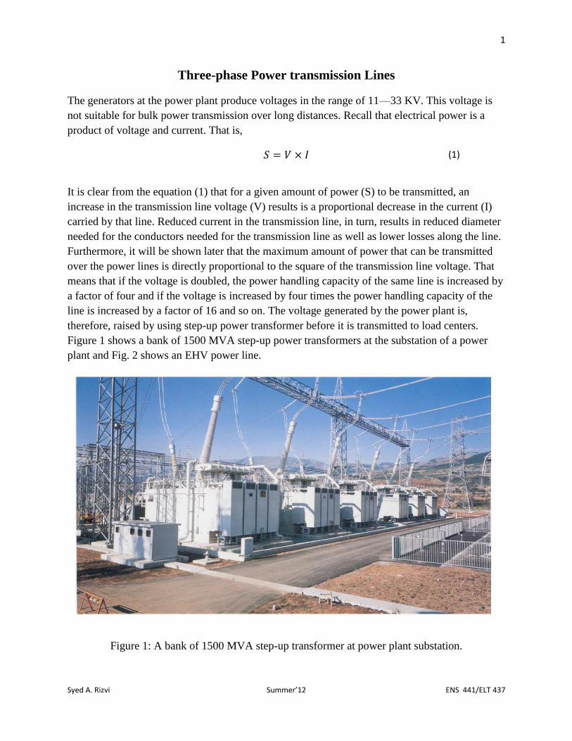
Figure 1 shows a bank of 1500 MVA step-up power transformers at the substation of a power
plant and Fig. 2 shows an EHV power line.
Figure 1: A bank of 1500 MVA step-up transformer at power plant substation.
2
Syed A. Rizvi Summer’12 ENS 441/ELT 437
IEEE defines the voltage ranges as follows:
Low voltage (LV) up to 600 V
Medium voltage (MV) 601—69000 V
High voltage (HV) 69001—230000 V
Extra high voltage (EHV) 230001—800000 V
Ultra high voltage (UHV) < 800000 V
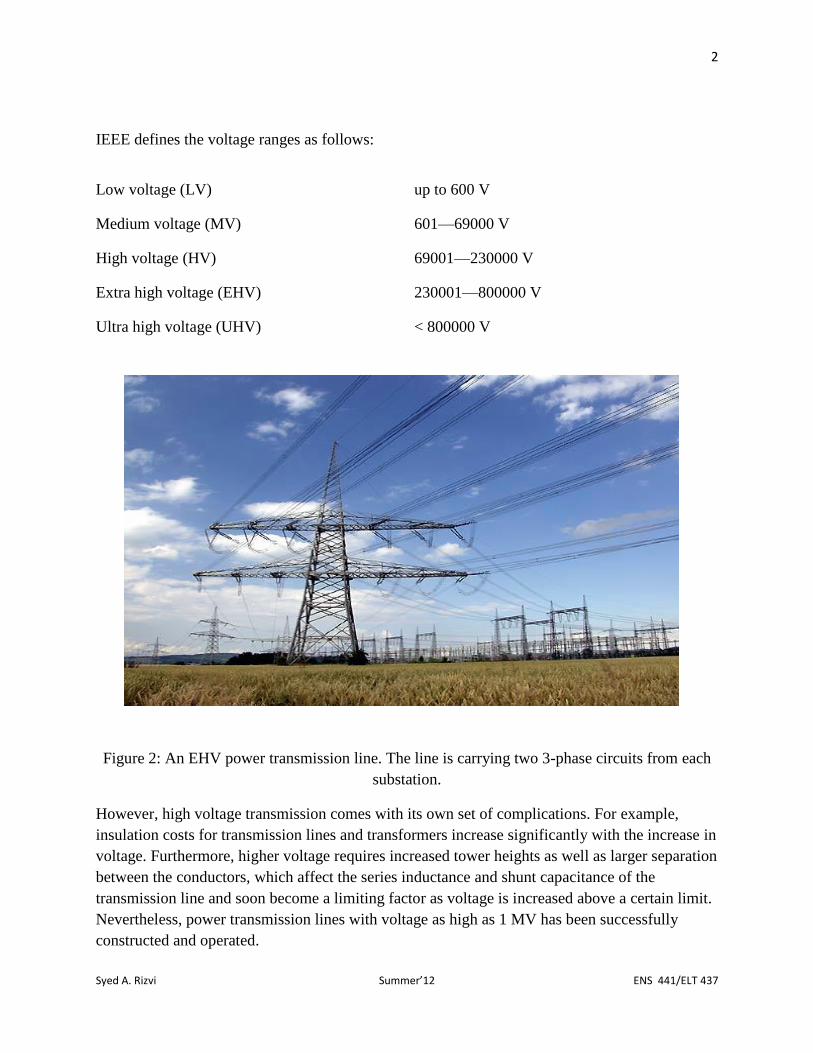
Figure 2: An EHV power transmission line. The line is carrying two 3-phase circuits from each
substation.
However, high voltage transmission comes with its own set of complications. For example,
insulation costs for transmission lines and transformers increase significantly with the increase in
voltage. Furthermore, higher voltage requires increased tower heights as well as larger separation
between the conductors, which affect the series inductance and shunt capacitance of the
transmission line and soon become a limiting factor as voltage is increased above a certain limit.
Nevertheless, power transmission lines with voltage as high as 1 MV has been successfully
constructed and operated.

3
Syed A. Rizvi Summer’12 ENS 441/ELT 437
An important goal of any power transmission system is to deliver power reliably at a constant
voltage under varying load conditions. Voltage drop along the transmission line due to the line
impedance can reduce the voltage at the receiving end of a transmission line, which is
undesirable. The line impedance is composed of resistance as well as inductive and capacitive
reactance. However, depending on the length of the transmission line one may be more dominant
than the other. The transmission lines are divided into three categories, which are based on the
length of a line.
(1) Short transmission lines: These lines are up to 50 miles long. These lines are
largely resistive in nature.
(2) Medium transmission line: These lines are longer than 50 miles and are up to 150
miles long. These lines are largely inductive in nature.
(3) Long transmission lines: These lines are longer than 150 miles. These lines are
largely inductive and capacitive in nature.
Inductance of a Transmission Line:
Series inductance, L, of a transmission line depends upon several factors, including the
separation, D, between two conductors in the transmission line and the radius, r, of the conductor
(see Fig. 3).
Figure 3: Two conductors of a transmission line of radius “r” separated a distance D.
The inductance per meter length of a single phase transmission line consisting of two conductors
(one line and one neutral) is given by

4
Syed A. Rizvi Summer’12 ENS 441/ELT 437
𝐿 =
𝜇
𝜋(1
4+ ln
𝐷
𝑟) 𝐻/𝑚 (2)
Where,
µ = permeability of the material
D = separation between two conductors
r = radius of the conductor.
For a fixed power to be transmitted, as the voltage of the transmission line increases the current
carried by the transmission line decreases reducing the radius of the conductor needed for the
line. Furthermore, higher voltage requires larger separation between the conductors.
Consequently, the inductance of the line increases with the increase in voltage. Therefore,
instead of using a single conductor, multiple conductors are bundled together to form a ring,
which significantly increases the effective radius of the line carrying the current. That results in a
decrease in the inductance per unit length of the transmission line. Figure 4 shows two EHV
lines with bundled conductors
(a) (b)
Figure 4: EHV transmission line (a) with eight bundled conductors, (b) with four bundled
conductors.

5
Syed A. Rizvi Summer’12 ENS 441/ELT 437
Capacitance of a Transmission Line:
The shunt capacitance per meter length of a single phase transmission line consisting of two
conductors (one line and one neutral) is given by
𝐶 =
2 × 𝜋 × 𝜖
ln𝐷𝑟
𝐹/𝑚 (3)
where,
𝜖 = permittivity of free space
D = separation between two conductors
r = radius of the conductor.
For a fixed power to be transmitted, as the voltage of the transmission line increases, the reduced
radius and increased separation between the conductors result in decreased capacitance.
However, as discussed earlier, this results in an increase in line inductance. On the other hand,
bundled conductors used to increase the effective radius of the transmission line result in
decreasing the line inductance. However, as can be seen from Eq. (3), any increase in “r” results
in an increase in line capacitance. In practice, it is a trade-off between the acceptable level of line
inductance and capacitance.
Power Flow through the Transmission Line:
As mentioned earlier, an important goal of power transmission systems is to reliably deliver
power at constant voltages at the receiving end under varying load conditions. The changes in
load conditions result in changing the current through the transmission line causing line drop to
change. That result in fluctuations in the voltage at the receiving end, which is undesirable. In the
medium and long transmission lines, the line reactance is much higher than the line resistance
and, therefore, for all practical purposes the line resistance can safely ignored and these lines are
considered reactive in nature. From the power flow perspective, a higher line current for a given
transmission line means more reactive power absorbed by the line, which the source has to
supply. If the receiving end, somehow, provides some of the reactive power absorbed by the
lines, it would reduce the burden on the source thus reducing the line current and the line drop.
This can be achieved, for example, placing capacitor banks the receiving end, which act a source
of reactive power.
Assignment 3.1: Voltage regulation using capacitor banks parallel to the load.
Components needed:
Resistors: 75 Ω (3)
6
Syed A. Rizvi Summer’12 ENS 441/ELT 437
Inductors: 15 mH (6)
Capacitors: 20/5 µF (6)
35/5 µF (6)
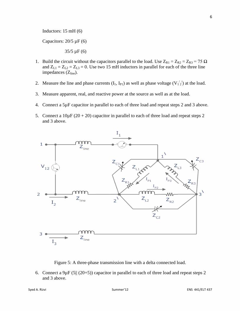
1. Build the circuit without the capacitors parallel to the load. Use ZR1 = ZR2 = ZR3 = 75 Ω
and ZL1 = ZL2 = ZL3 = 0. Use two 15 mH inductors in parallel for each of the three line
impedances (Zline).
2. Measure the line and phase currents (I1, IP1) as well as phase voltage (V1/2/) at the load.
3. Measure apparent, real, and reactive power at the source as well as at the load.
4. Connect a 5µF capacitor in parallel to each of three load and repeat steps 2 and 3 above.
5. Connect a 10µF (20 + 20) capacitor in parallel to each of three load and repeat steps 2
and 3 above.
Figure 5: A three-phase transmission line with a delta connected load.
6. Connect a 9µF (5|| (20+5)) capacitor in parallel to each of three load and repeat steps 2
and 3 above.
7
Syed A. Rizvi Summer’12 ENS 441/ELT 437
7. Connect a 8.375µF ((5+20) ||(5+35)) capacitor in parallel to each of three load and repeat
steps 2 and 3 above.
8. Explain your results.
Assignment 3.2: Perform the experiment # 4: Power flow and voltage regulation of a simple
transmission line from the manual of Electric Power Transmission System.
Assignment 3.3: Perform the experiment # 5: Phase angle and voltage drop between sender and
receiver from the manual of Electric Power Transmission System.
Real and Reactive Power Flow
For medium and long lines, which are largely reactive in nature, the real and reactive power flow
depends on the voltage as well phase difference at the two sides of the transmission line. Real
power can only flow if the voltages on both sides of the transmission line are out of phase and
the flow of real power is from the side having a voltage with a leading phase angle to the side
having a lagging phase angle.
Let’s assume the sending end voltage (VS) and the receiving end voltage (VR), both measured
line to neutral, are in phase and the net line reactance is inductive. That is,
𝑉𝑆 = 𝑉1⟨∅
𝑉𝑅 = 𝑉2⟨∅
𝑍𝑙𝑖𝑛𝑒 = 𝑋𝑙⟨90𝑜
𝐼𝑙𝑖𝑛𝑒 = 𝐼𝑙 =𝑉1⟨∅ − 𝑉2⟨∅
𝑋𝑙⟨90𝑜=
(𝑉1 − 𝑉2)⟨∅
𝑋𝑙⟨90𝑜=
(𝑉1 − 𝑉2)
𝑋𝑙
⟨(∅ − 90𝑜).
The conjugate of the line current, Il*, is given by
𝐼𝑙∗ =
(𝑉1 − 𝑉2)
𝑋𝑙
⟨(90𝑜 − ∅)
and the apparent power, S, can be computed as
𝑆 = 𝑉𝑆 × 𝐼𝑙∗ = 𝑉1⟨∅ ×
(𝑉1 − 𝑉2)
𝑋𝑙
⟨(90𝑜 − ∅) = 𝑉1 ×(𝑉1 − 𝑉2)
𝑋𝑙
⟨(90𝑜 − ∅ + ∅)
or
𝑆 = 𝑉1 ×
(𝑉1 − 𝑉2)
𝑋𝑙
⟨90𝑜 (4)

8
Syed A. Rizvi Summer’12 ENS 441/ELT 437
and, finally, we can see that
𝑅𝑒𝑎𝑙 𝑃𝑜𝑤𝑒𝑟 = 𝑃 = 𝑆 cos 90𝑜 = 0.
It can be seen that the reactive power will flow when VS and VR are in-phase as long as |VS| ≠
|VR|. Furthermore, the reactive power will flow regardless of the magnitude of VS and VR as long
as VS and VR are out-of-phase. However, the direction of power flow will be from a higher
voltage to lower voltage. In the special case when |VS| = |VR|, the reactive power will flow from
both sides, in equal amount, to furnish the reactive absorbed by the line. The table below
summarizes the real and reactive power flow under different conditions. Let’s assume
𝑉𝑆 = 𝑉1⟨∅1
𝑉𝑅 = 𝑉2⟨∅2
Magnitude of the voltages Phase Direction of reactive power flow
V1 = V2 ϕ1 = ϕ2 No power flow
V1 > V2 ϕ1 = ϕ2 From VS to VR
V1 < V2 ϕ1 = ϕ2 From VR to VS
V1 = V2 ϕ1 ≠ ϕ2 From VS to the line and VR to the line
(equal amount)
V1 > V2 ϕ1 > ϕ2 From VS to VR
V1 > V2 ϕ1 < ϕ2 From VS to VR
V1 < V2 ϕ1 > ϕ2 From VR to VS
V1 < V2 ϕ1 < ϕ2 From VR to VS
Assignment 3.4: Perform the experiment # 6: Parameters which affect real and reactive power
flow from the manual of Electric Power Transmission System.
9
Syed A. Rizvi Summer’12 ENS 441/ELT 437
Power Handling Capacity of a Transmission Line
For medium and long line where the line impedance is largely reactive, the real power handling
capacity of the lines, for given sending and receiving end voltage, depends upon the phase
difference between the sending and receiving end voltages. Let’s assume the sending end
voltage, VS, is leading the receiving end voltage, VR, by an angle “θ.” Let’s also assume that the
line current, IS = IR, is at a phase angle ϕ w.r.t. receiving end voltage VR. We will assume that
these are line-to-neutral voltage so that we can compute real power per phase delivered by the
sending end. That is
𝑉𝑆 = 𝑉1⟨𝜃
𝑉𝑅 = 𝑉2⟨0
𝐼𝑆 = 𝐼𝑅 = 𝐼⟨∅
𝑍𝑙𝑖𝑛𝑒 = 𝑋𝑙⟨90𝑜
The real power, P, delivered to the load (per phase) is given by
𝑃/𝑝ℎ𝑎𝑠𝑒 = 𝑉𝑅 × 𝐼𝑅 × cos ∅ = 𝑉𝑅 × 𝐼 × cos ∅. (5)
also,
𝑉𝑆 = 𝐼𝑆 × 𝑍𝑙𝑖𝑛𝑒 + 𝑉𝑅 = 𝐼⟨∅ × 𝑋𝑙⟨90𝑂 + 𝑉2⟨0𝑂 =𝐼 × 𝑋𝑙⟨(∅ + 90𝑂) + 𝑉2
or
𝑉𝑆 = 𝐼 × 𝑋𝑙[cos(∅ + 90𝑂) + 𝑗 sin(∅ + 90𝑂)] + 𝑉2, (6)
but
cos ∅ = sin(∅ + 90𝑂) (7)
and
− sin ∅ = cos(∅ + 90𝑂). (8)
Substituting Eqs. (7) and (8) in Eq. (6) yields
𝑉𝑆 = 𝐼 × 𝑋𝑙[−sin ∅ + 𝑗 cos ∅] + 𝑉2, (9)
or
𝑉𝑆 = (𝐼 × 𝑋𝑙[−sin ∅] + 𝑉2) + 𝑗 𝐼 × 𝑋𝑙 cos ∅, (10)
but
10
Syed A. Rizvi Summer’12 ENS 441/ELT 437
𝑉𝑆 = 𝑉1 cos 𝜃 + 𝑗𝑉1 sin 𝜃. (11)
Comparing imaginary parts of Eqs. (10) and (11) we get
𝐼 × 𝑋𝑙 cos ∅ = 𝑉1 sin 𝜃 (12)
or
𝐼 cos ∅ =
𝑉1 sin 𝜃
𝑋𝑙. (13)
Substituting Eq. (13) into Eq. (5) yields
𝑃/𝑝ℎ𝑎𝑠𝑒 =
𝑉2𝑉1 sin 𝜃
𝑋𝑙, (14)
and for a balanced 3-phase load the total power, PT, is given by
𝑃𝑇 =
3 × 𝑉2𝑉1 sin 𝜃
𝑋𝑙. (15)
If V1 = V2 = V and the line-to-line voltage 𝑉𝐿𝐿 = √3 𝑉, the Eq. (15) becomes
𝑃𝑇 =
3 × 𝑉2 sin 𝜃
𝑋𝑙=
√3 × 𝑉 × √3 × 𝑉 sin 𝜃
𝑋𝑙=
𝑉𝐿𝐿2 sin 𝜃
𝑋𝑙. (16)
It can be seen from Eq. (16) the power handling capacity of a 3-phase transmission line is
directly proportional to the square of the voltage.
Assignment 3.5: Perform the experiment # 7: Parallel lines, transformers, and power handling
capacity from the manual of Electric Power Transmission System.

11
Syed A. Rizvi Summer’12 ENS 441/ELT 437
Phase Shift Transformer
A phase shift transformer changes the phase of the secondary windings w.r.t. the corresponding
primary windings of the transformer without changing the voltage ratio. Figure 6 shows a phase
shift transformer that produces a 60o shift between the primary and the secondary of the
transformer.
Figure 6: A phase shift transformer.
Assignment 3.6: For the phase shift transformer in Fig. 6, if the terminal voltages are as follows:
Primary voltages:
𝑉𝐴𝑁 =𝑉
√3⟨0𝑂
𝑉𝐵𝑁 =𝑉
√3⟨−120𝑂

12
Syed A. Rizvi Summer’12 ENS 441/ELT 437
𝑉𝐶𝑁 =𝑉
√3⟨−240𝑂
𝑉𝐴𝐵 = 𝑉⟨30𝑂
𝑉𝐵𝐶 = 𝑉⟨−90𝑂
𝑉𝐶𝐴 = 𝑉⟨−210𝑂
Secondary voltages:
𝑉𝑎11,𝑎12 = 𝑉𝑎21,𝑎22 =𝑉
2⟨30𝑂
𝑉𝑏11,𝑏12 = 𝑉𝑏21,𝑏22 =𝑉
2⟨−90𝑂
𝑉𝑐11,𝑐12 = 𝑉𝑐21,𝑐22 =𝑉
2⟨−210𝑂
show that
𝑉𝑎𝑁 = 𝑉𝑎11,𝑎12 + 𝑉𝑐11,𝑐12 =𝑉
2⟨90𝑂
𝑉𝑏𝑁 = 𝑉𝑏11,𝑏12 + 𝑉𝑎21,𝑎22 =𝑉
2⟨−30𝑂
𝑉𝑐𝑁 = 𝑉𝑐21,𝑐22 + 𝑉𝑏21,𝑏22 =𝑉
2⟨−150𝑂
Also, build the phase shift transformer and verify your answers.
Assignment 3.7: Perform the experiment # 11: Transmission line networks and the buck-boost,
phase shift transformer from the manual of Electric Power Transmission System.