three dimensional displacement response study of a rubble
TRANSCRIPT
Three Dimensional Displacement Response Study of a Rubble-House Using a 3D
Laser Scanner
W.Barham1, F. Oncul
2, P. Meadati
3 and M. Oguzmert
4
1Assistant Professor, Civil & Construction Engineering, email: [email protected]
2Assistant Professor, Civil Engineering Technology, [email protected]
3Assistant Professor, Construction Management, email: [email protected]
4Assistant Professor, Civil & Construction Engineering, email: [email protected]
Southern Polytechnic State University
ABSTRACT
After the devastating earthquake that hit Haiti in January 2010, a number of
non-profit organizations started building cost effective replacement homes for the
needy using the rubble from collapsed buildings. Rubble-Houses are environmentally
friendly structures with walls comprised of recycled loose rubble placed in welded
wire baskets. Rubble-Houses are assumed to be earthquake resistant structures due to
their improved damping and ductility characteristics arising from the rubble and
welded wire basket, respectively. However, the response of such structures under
static and dynamic loads has not been studied in detail. In order to have a better
understanding of its behavior, a full-scale rubble-house was built in the middle of
Southern Polytechnic State University campus and subjected to a series of in-plane
and out-of-plane static loads. Wall displacements were recorded using a 3D laser
scanning technique in addition to total station and displacement gauge measurements.
3D laser scanning is an effective and efficient approach for precise and dimensionally
accurate as-built documentation. This paper presents and discusses the use of 3D
laser scanning technique in measuring the displacement response of a rubble-house
under static loads.
INTRODUCTION
A 7.0 magnitude earthquake struck Haiti on January 12th
, 2010. The Haitian
government estimates that 200,000 have died as a result of this sad incident,
2,000,000 people have been left homeless and 3,000,000 people are in need of
emergency aid. The United States Geological Survey (USGS) reported that the
earthquake was the strongest earthquake to hit the area since 1770.
Shortly after the earthquake, relief organizations from around the world joined
forces to support the devastated communities in carrying out rescue operations and
supplying food, shelter, medical aid and providing sanitation, etc. The most
challenging issue was proving shelter to millions of people who lost their homes.
Conscience International, a non-profit humanitarian and advocacy organization,
started building homes for the Haitian out of the destroyed concrete, or rubble.
Rubble-Houses are environmentally friendly structures that recycle the broken

concrete from destroyed buildings to build the walls and are assumed to be
earthquake resistant. The earthquake left huge quantities of rubble that could be used
in the reconstruction of Haitians’ homes.
Rubble-Houses’ walls comprised of welded wire baskets filled with loose
rubble seemed to be an inexpensive and immediate solution for the needy. Such
structures are assumed to be earthquake resistant structures due to their improved
damping and ductility characteristics arising from the rubble and welded wire basket.
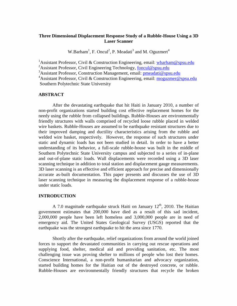
In August 2011, a collaborative research effort between Southern Polytechnic State
University and Conscience International initiated to assess the seismic resistance of
such rubble houses. A full-scale structure (14 ft. wide, 20 ft. long and 8 ft. tall), as
shown in Figure 1 below, was built in the middle of Southern Polytechnic State
University’ campus and subjected to series of in-plane and out of plane static loads.
Figure 1. Rubble-House
In order to understand the mechanical behavior of the rubble walls, the
displacement response map of the walls was recorded using a 3D laser scanning
technique. 3D laser scanning is a very effective and efficient approach for precise and
dimensionally accurate 3D as-built documentation. 3D laser scanning is a process of
collecting the spatial coordinates of millions of points of an object by using lasers.
The point clouds generated in this process are useful for measurement and
visualization applications. This approach reduces errors and rework during
documentation and enhances the productivity in a construction process.
3D laser scanning technique has been successfully used for various
architecture, engineering and construction applications (Shin and Wang 2004; Olsen
et al. 2010; Jaselskis 2005). Walters et al. (2008) used laser scanners to determine the
thickness of concrete pavement. Tsakiri et al. (2006) calculated the deformations
through usage of surface reconstruction and deformation extraction techniques from
laser scanner data. Gordon and Lichti (2007) used laser scanner data for modeling to
calculate the precise structural deformation. Chang et al. (2008) used 3D laser
scanner data for deformation calculations for evaluating the structural safety.
This paper presents and discusses the usage of the 3D Laser Technique in
measuring the displacement response of structures under static loads.
RUBBLE HOUSE CONSTRUCTION
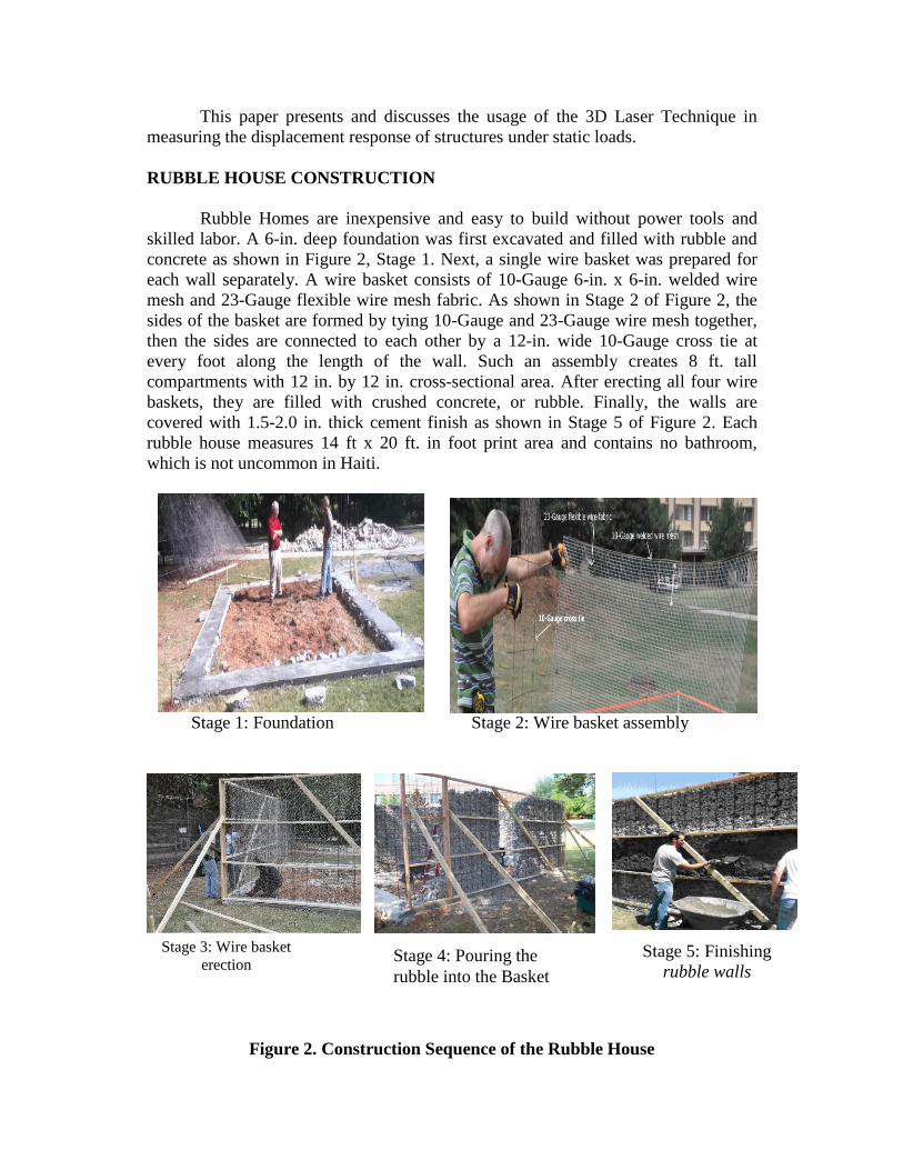
Rubble Homes are inexpensive and easy to build without power tools and
skilled labor. A 6-in. deep foundation was first excavated and filled with rubble and
concrete as shown in Figure 2, Stage 1. Next, a single wire basket was prepared for
each wall separately. A wire basket consists of 10-Gauge 6-in. x 6-in. welded wire
mesh and 23-Gauge flexible wire mesh fabric. As shown in Stage 2 of Figure 2, the
sides of the basket are formed by tying 10-Gauge and 23-Gauge wire mesh together,
then the sides are connected to each other by a 12-in. wide 10-Gauge cross tie at
every foot along the length of the wall. Such an assembly creates 8 ft. tall
compartments with 12 in. by 12 in. cross-sectional area. After erecting all four wire
baskets, they are filled with crushed concrete, or rubble. Finally, the walls are
covered with 1.5-2.0 in. thick cement finish as shown in Stage 5 of Figure 2. Each
rubble house measures 14 ft x 20 ft. in foot print area and contains no bathroom,
which is not uncommon in Haiti.
Stage 1: Foundation Stage 2: Wire basket assembly
Stage 3: Wire basket
erection
Figure 2. Construction Sequence of the Rubble House
Stage 4: Pouring the
rubble into the Basket
Stage 5: Finishing
rubble walls
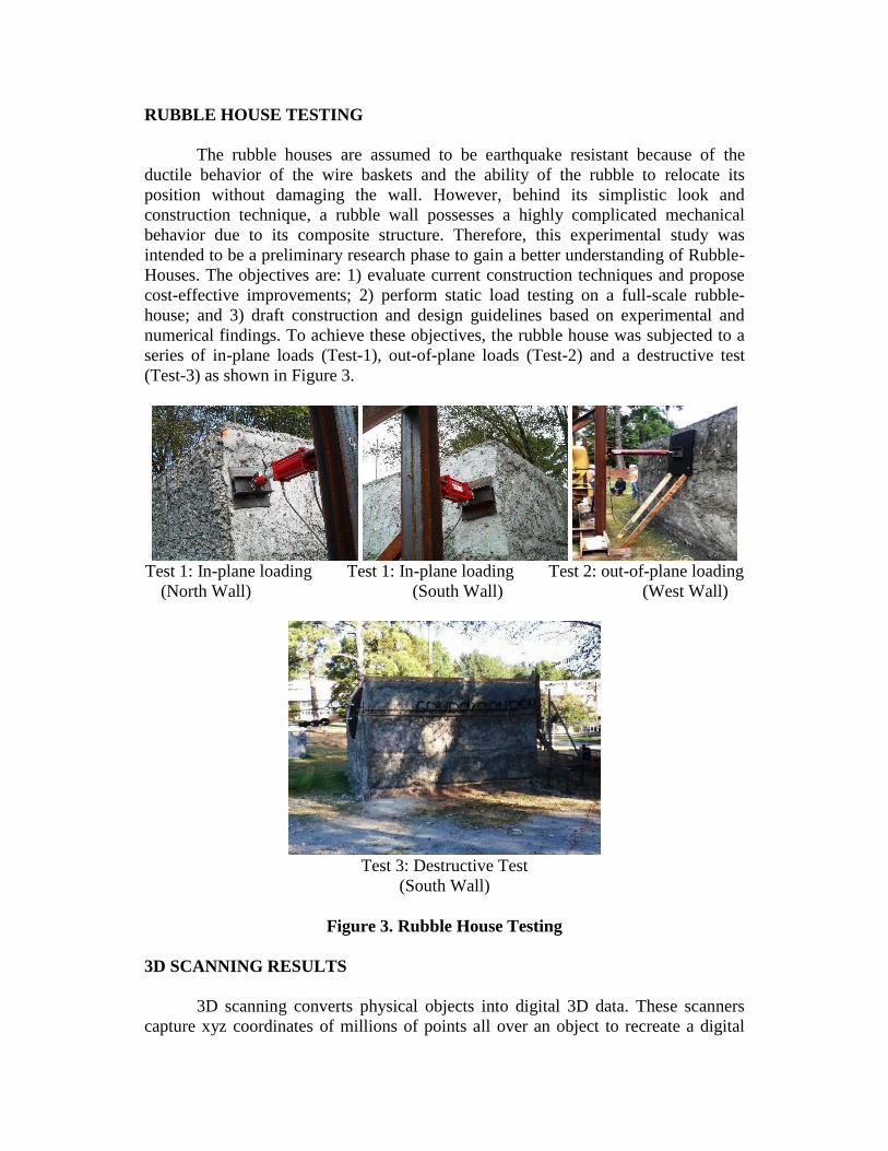
RUBBLE HOUSE TESTING
The rubble houses are assumed to be earthquake resistant because of the
ductile behavior of the wire baskets and the ability of the rubble to relocate its
position without damaging the wall. However, behind its simplistic look and
construction technique, a rubble wall possesses a highly complicated mechanical
behavior due to its composite structure. Therefore, this experimental study was
intended to be a preliminary research phase to gain a better understanding of Rubble-
Houses. The objectives are: 1) evaluate current construction techniques and propose
cost-effective improvements; 2) perform static load testing on a full-scale rubble-
house; and 3) draft construction and design guidelines based on experimental and
numerical findings. To achieve these objectives, the rubble house was subjected to a
series of in-plane loads (Test-1), out-of-plane loads (Test-2) and a destructive test
(Test-3) as shown in Figure 3.
Test 1: In-plane loading Test 1: In-plane loading Test 2: out-of-plane loading
(North Wall) (South Wall) (West Wall)
Test 3: Destructive Test
(South Wall)
Figure 3. Rubble House Testing
3D SCANNING RESULTS
3D scanning converts physical objects into digital 3D data. These scanners
capture xyz coordinates of millions of points all over an object to recreate a digital
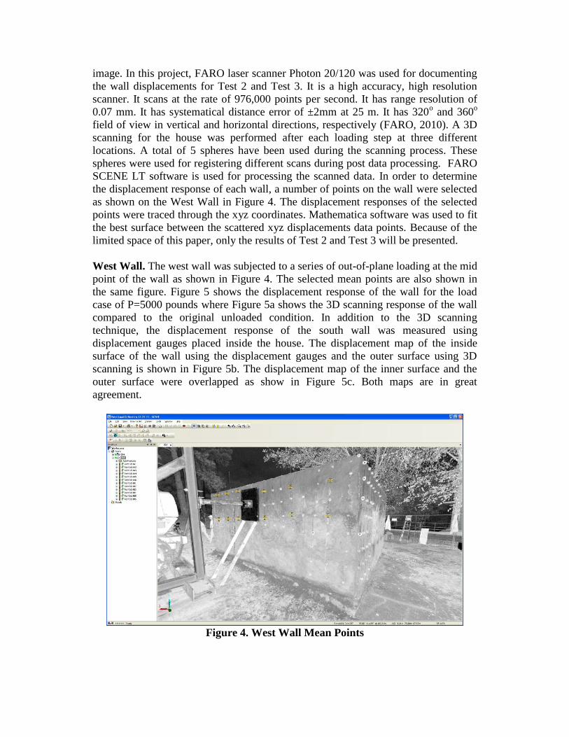
image. In this project, FARO laser scanner Photon 20/120 was used for documenting
the wall displacements for Test 2 and Test 3. It is a high accuracy, high resolution
scanner. It scans at the rate of 976,000 points per second. It has range resolution of
0.07 mm. It has systematical distance error of ±2mm at 25 m. It has 320o and 360
o
field of view in vertical and horizontal directions, respectively (FARO, 2010). A 3D
scanning for the house was performed after each loading step at three different
locations. A total of 5 spheres have been used during the scanning process. These
spheres were used for registering different scans during post data processing. FARO
SCENE LT software is used for processing the scanned data. In order to determine
the displacement response of each wall, a number of points on the wall were selected
as shown on the West Wall in Figure 4. The displacement responses of the selected
points were traced through the xyz coordinates. Mathematica software was used to fit
the best surface between the scattered xyz displacements data points. Because of the
limited space of this paper, only the results of Test 2 and Test 3 will be presented.
West Wall. The west wall was subjected to a series of out-of-plane loading at the mid
point of the wall as shown in Figure 4. The selected mean points are also shown in
the same figure. Figure 5 shows the displacement response of the wall for the load
case of P=5000 pounds where Figure 5a shows the 3D scanning response of the wall
compared to the original unloaded condition. In addition to the 3D scanning
technique, the displacement response of the south wall was measured using
displacement gauges placed inside the house. The displacement map of the inside
surface of the wall using the displacement gauges and the outer surface using 3D
scanning is shown in Figure 5b. The displacement map of the inner surface and the
outer surface were overlapped as show in Figure 5c. Both maps are in great
agreement.
Figure 4. West Wall Mean Points

Figure 5a: Deformed shape vs. undeformed shape
Figure 5. Displacement response of west wall
South Wall. In the destructive test, the south wall was subjected to a pull from
behind loading up to the collapse level. The displacement responses were recorded at
three loading levels, namely 6 kip, 12 kip, and 15 kip (just before failure). Figure 6
shows the test setup and the selected mean points. The Displacement map is shown in
Figure 7 for the three loading conditions. The walls of the rubble house sit on the
foundation. A number of dowel rebars were embedded in each side of the foundation
Figure 5b: 3D scanning results
(outer surface) vs. displacement
gauge results (inner surface)
Figure 5c: 3D scanning
results vs. displacement
gauge results
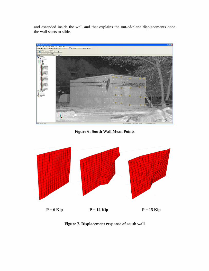
and extended inside the wall and that explains the out-of-plane displacements once
the wall starts to slide.
Figure 6: South Wall Mean Points
P = 6 Kip P = 12 Kip P = 15 Kip
Figure 7. Displacement response of south wall

CONCLUSION
This paper presented the usage of 3D laser scanning technique to record the
displacement response of a rubble-house under static loading. 3D scanning of an
object produces millions of points stored in xyz coordinates format. To extract the
deformed shape of each wall, sample area mean points were selected on each wall.
After each loading, the displacements of the mean points were calculated by
comparing the xyz coordinate of the current scan with the previous scan.
Mathematica software was used to fit the best surface between the scattered xyz
displacements data points. In one case, the displacement of 3D scanning was
compared with the displacement obtained using simple displacement gauges.
Although 3D scanning seems to be a very accurate technique in measuring the
displacement response of structures, more work needs to be done to simplify the data
extraction and manipulation.
REFERENCES
Chang, Y. Lai, S, Peng, S., Chang, K., and Tu, Y. (2008). Data Processing of 3D
laser scanning on structural deformation. Integrating Generations FIG working
week, Stockholm, Sweden, June 14-19, 2008.
FARO (2010). “FARO Laser Scanner Photon 20/120 user’s manual”
Gordon S.J. and Lichti D.D. (2007). “Modeling terrestrial laser scanner data for
precise structural deformation measurement.” Journal of Surveying
Engineering 133(2) 72-80.
Jaselskis, E., Gao, Z., and Walters, R. (2005). “Improving transportation projects
using laser scanning.” Journal of Construction Engineering and Management,
131 (3), 377-384
Olsen, M., Kuester, F., Chang, B., and Hutchison, T. (2010). “Terrestrial laser
scanning based structural damage assessment.” Journal of Computation in
Civil Engineering, 24(3), 264-272.
Shih, N. and Wang, P. (2004). “Point cloud based comparison between construction
schedule and as-built progress: Long range three dimensional laser scanner’s
approach.” Journal of architectural Engineering, 10(3), 98-102.
Tsakiri, M., Lichti, D. and Pfeifer, N. (2006). “Terrestrial laser scanning for
deformation monitoring.” Proceedings of 3rd IAG/12th FIG Symposium,
Baden, May 22-24, 2006.
Walters, R., Jaselskis, E., Zhang, J. Mueller, K. and Kaewmoracharoen (2008).
“Using scanning lasers to determine the thickness of concrete pavement.”
Journal of Construction Engineering Management 134(8) 583-591.